im927 weldmark 225 - lincoln electric · tools away from v-belts, gears, fans and all other moving...
TRANSCRIPT

WELDMARK 225
OPERATOR’ S MANUAL
For Machines with Code Number 11396
IM927January, 2007
Safety Depends on YouLincoln arc welding and cutting
equipment is designed and built
with safety in mind. However,
your overal l safety can be
increased by proper installation ...
and thoughtful operation on your
part. DO NOT I NSTALL,
OPERATE OR REPAI R THI S
EQUI PMENT WI THOUT READ-
I NG THI S MANUAL AND THE
SAFETY PRECAUTI ONS CON-
TAI NED THROUGHOUT. And,
most importantly, think before you
act and be careful.
R
R
• Manufactured by Lincoln Electric Company •
Cleveland, Ohio 44117-1199 U.S.A. TEL: 216.481.8100 FAX: 216.486.1751 WEB SITE: www.lincolnelectric.com
Copyright © 2007 Lincoln Global Inc.
C US
WELDMARK 225
This manual covers equipment which is no longer in production by The Lincoln Electric Co. Speci�cations and availability of optional features may have changed.

FOR ENGINEpowered equipment.
1.a. Turn the engine off before troubleshooting and maintenancework unless the maintenance work requires it to be running.
____________________________________________________1.b. Operate engines in open, well-ventilated
areas or vent the engine exhaust fumes outdoors.
____________________________________________________1.c. Do not add the fuel near an open flame
welding arc or when the engine is running.Stop the engine and allow it to cool beforerefueling to prevent spilled fuel from vaporiz-ing on contact with hot engine parts andigniting. Do not spill fuel when filling tank. Iffuel is spilled, wipe it up and do not startengine until fumes have been eliminated.
____________________________________________________
1.d. Keep all equipment safety guards, covers and devices in
position and in good repair.Keep hands, hair, clothing and
tools away from V-belts, gears, fans and all other moving
parts when starting, operating or repairing equipment.
____________________________________________________
1.e. In some cases it may be necessary to remove safetyguards to perform required maintenance. Removeguards only when necessary and replace them when themaintenance requiring their removal is complete.Always use the greatest care when working near movingparts.
___________________________________________________1.f. Do not put your hands near the engine fan.
Do not attempt to override the governor oridler by pushing on the throttle control rodswhile the engine is running.
___________________________________________________1.g. To prevent accidentally starting gasoline engines while
turning the engine or welding generator during maintenancework, disconnect the spark plug wires, distributor cap ormagneto wire as appropriate.
iSAFETYi
ARC WELDING CAN BE HAZARDOUS. PROTECT YOURSELF AND OTHERS FROM POSSIBLE SERIOUS INJURY OR DEATH.KEEP CHILDREN AWAY. PACEMAKER WEARERS SHOULD CONSULT WITH THEIR DOCTOR BEFORE OPERATING.
Read and understand the following safety highlights. For additional safety information, it is strongly recommended that youpurchase a copy of “Safety in Welding & Cutting - ANSI Standard Z49.1” from the American Welding Society, P.O. Box351040, Miami, Florida 33135 or CSA Standard W117.2-1974. A Free copy of “Arc Welding Safety” booklet E205 is availablefrom the Lincoln Electric Company, 22801 St. Clair Avenue, Cleveland, Ohio 44117-1199.
BE SURE THAT ALL INSTALLATION, OPERATION, MAINTENANCE AND REPAIR PROCEDURES AREPERFORMED ONLY BY QUALIFIED INDIVIDUALS.
WARNING
Mar ‘95
ELECTRIC AND MAGNETIC FIELDSmay be dangerous
2.a. Electric current flowing through any conductor causes
localized Electric and Magnetic Fields (EMF). Welding
current creates EMF fields around welding cables and
welding machines
2.b. EMF fields may interfere with some pacemakers, and
welders having a pacemaker should consult their physician
before welding.
2.c. Exposure to EMF fields in welding may have other health
effects which are now not known.
2.d. All welders should use the following procedures in order to
minimize exposure to EMF fields from the welding circuit:
2.d.1. Route the electrode and work cables together - Secure
them with tape when possible.
2.d.2. Never coil the electrode lead around your body.
2.d.3. Do not place your body between the electrode and
work cables. If the electrode cable is on your right
side, the work cable should also be on your right side.
2.d.4. Connect the work cable to the workpiece as close as
possible to the area being welded.
2.d.5. Do not work next to welding power source.
1.h. To avoid scalding, do not remove theradiator pressure cap when the engine ishot.
CALIFORNIA PROPOSITION 65 WARNINGS
Diesel engine exhaust and some of its constituentsare known to the State of California to cause can-cer, birth defects, and other reproductive harm.
The engine exhaust from this product containschemicals known to the State of California to causecancer, birth defects, or other reproductive harm.
The Above For Diesel Engines The Above For Gasoline Engines
WELDMARK 225
iiSAFETYii
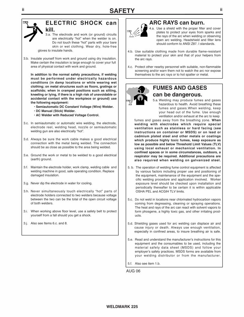
ARC RAYS can burn.4.a. Use a shield with the proper filter and cover
plates to protect your eyes from sparks andthe rays of the arc when welding or observingopen arc welding. Headshield and filter lensshould conform to ANSI Z87. I standards.
4.b. Use suitable clothing made from durable flame-resistantmaterial to protect your skin and that of your helpers fromthe arc rays.
4.c. Protect other nearby personnel with suitable, non-flammablescreening and/or warn them not to watch the arc nor exposethemselves to the arc rays or to hot spatter or metal.
ELECTRIC SHOCK cankill.3.a. The electrode and work (or ground) circuits
are electrically “hot” when the welder is on.
Do not touch these “hot” parts with your bare
skin or wet clothing. Wear dry, hole-free
gloves to insulate hands.
3.b. Insulate yourself from work and ground using dry insulation.
Make certain the insulation is large enough to cover your full
area of physical contact with work and ground.
In addition to the normal safety precautions, if weldingmust be performed under electrically hazardousconditions (in damp locations or while wearing wetclothing; on metal structures such as floors, gratings orscaffolds; when in cramped positions such as sitting,kneeling or lying, if there is a high risk of unavoidable oraccidental contact with the workpiece or ground) usethe following equipment:
• Semiautomatic DC Constant Voltage (Wire) Welder.• DC Manual (Stick) Welder.• AC Welder with Reduced Voltage Control.
3.c. In semiautomatic or automatic wire welding, the electrode,
electrode reel, welding head, nozzle or semiautomatic
welding gun are also electrically “hot”.
3.d. Always be sure the work cable makes a good electrical
connection with the metal being welded. The connection
should be as close as possible to the area being welded.
3.e. Ground the work or metal to be welded to a good electrical
(earth) ground.
3.f. Maintain the electrode holder, work clamp, welding cable and
welding machine in good, safe operating condition. Replace
damaged insulation.
3.g. Never dip the electrode in water for cooling.
3.h. Never simultaneously touch electrically “hot” parts of
electrode holders connected to two welders because voltage
between the two can be the total of the open circuit voltage
of both welders.
3.i. When working above floor level, use a safety belt to protect
yourself from a fall should you get a shock.
3.j. Also see Items 6.c. and 8.
WELDMARK 225
FUMES AND GASEScan be dangerous.5.a. Welding may produce fumes and gases
hazardous to health. Avoid breathing these
fumes and gases.When welding, keep
your head out of the fume. Use enough
ventilation and/or exhaust at the arc to keep
fumes and gases away from the breathing zone. Whenwelding with electrodes which require specialventilation such as stainless or hard facing (seeinstructions on container or MSDS) or on lead orcadmium plated steel and other metals or coatingswhich produce highly toxic fumes, keep exposure aslow as possible and below Threshold Limit Values (TLV)using local exhaust or mechanical ventilation. Inconfined spaces or in some circumstances, outdoors, arespirator may be required. Additional precautions arealso required when welding on galvanized steel.
5. b. The operation of welding fume control equipment is affected
by various factors including proper use and positioning of
the equipment, maintenance of the equipment and the spe-
cific welding procedure and application involved. Worker
exposure level should be checked upon installation and
periodically thereafter to be certain it is within applicable
OSHA PEL and ACGIH TLV limits.
5.c. Do not weld in locations near chlorinated hydrocarbon vapors
coming from degreasing, cleaning or spraying operations.
The heat and rays of the arc can react with solvent vapors to
form phosgene, a highly toxic gas, and other irritating prod-
ucts.
5.d. Shielding gases used for arc welding can displace air and
cause injury or death. Always use enough ventilation,
especially in confined areas, to insure breathing air is safe.
5.e. Read and understand the manufacturer’s instructions for this
equipment and the consumables to be used, including the
material safety data sheet (MSDS) and follow your
employer’s safety practices. MSDS forms are available from
your welding distributor or from the manufacturer.
5.f. Also see item 1.b.
AUG 06

FOR ELECTRICALLYpowered equipment.
8.a. Turn off input power using the disconnectswitch at the fuse box before working onthe equipment.
8.b. Install equipment in accordance with the U.S. NationalElectrical Code, all local codes and the manufacturer’srecommendations.
8.c. Ground the equipment in accordance with the U.S. NationalElectrical Code and the manufacturer’s recommendations.
CYLINDER may explodeif damaged.7.a. Use only compressed gas cylinders
containing the correct shielding gas for theprocess used and properly operatingregulators designed for the gas and
pressure used. All hoses, fittings, etc. should be suitable forthe application and maintained in good condition.
7.b. Always keep cylinders in an upright position securelychained to an undercarriage or fixed support.
7.c. Cylinders should be located:• Away from areas where they may be struck or subjected tophysical damage.
• A safe distance from arc welding or cutting operations andany other source of heat, sparks, or flame.
7.d. Never allow the electrode, electrode holder or any otherelectrically “hot” parts to touch a cylinder.
7.e. Keep your head and face away from the cylinder valve outletwhen opening the cylinder valve.
7.f. Valve protection caps should always be in place and handtight except when the cylinder is in use or connected foruse.
7.g. Read and follow the instructions on compressed gascylinders, associated equipment, and CGA publication P-l,“Precautions for Safe Handling of Compressed Gases inCylinders,” available from the Compressed Gas Association1235 Jefferson Davis Highway, Arlington, VA 22202.
iiiSAFETYiii
WELDMARK 225
Jan, 07
WELDING and CUTTINGSPARKS cancause fire or explosion.6.a. Remove fire hazards from the welding area.
If this is not possible, cover them to preventthe welding sparks from starting a fire.
Remember that welding sparks and hotmaterials from welding can easily go through small cracksand openings to adjacent areas. Avoid welding nearhydraulic lines. Have a fire extinguisher readily available.
6.b. Where compressed gases are to be used at the job site,special precautions should be used to prevent hazardoussituations. Refer to “Safety in Welding and Cutting” (ANSIStandard Z49.1) and the operating information for theequipment being used.
6.c. When not welding, make certain no part of the electrodecircuit is touching the work or ground. Accidental contactcan cause overheating and create a fire hazard.
6.d. Do not heat, cut or weld tanks, drums or containers until theproper steps have been taken to insure that such procedureswill not cause flammable or toxic vapors from substancesinside. They can cause an explosion even though they havebeen “cleaned”. For information, purchase “RecommendedSafe Practices for the Preparation for Welding and Cutting ofContainers and Piping That Have Held HazardousSubstances”, AWS F4.1 from the American Welding Society
(see address above).
6.e. Vent hollow castings or containers before heating, cutting orwelding. They may explode.
6.f. Sparks and spatter are thrown from the welding arc. Wear oilfree protective garments such as leather gloves, heavy shirt,cuffless trousers, high shoes and a cap over your hair. Wearear plugs when welding out of position or in confined places.Always wear safety glasses with side shields when in awelding area.
6.g. Connect the work cable to the work as close to the weldingarea as practical. Work cables connected to the buildingframework or other locations away from the welding areaincrease the possibility of the welding current passingthrough lifting chains, crane cables or other alternate cir-cuits. This can create fire hazards or overheat lifting chainsor cables until they fail.
6.h. Also see item 1.c.
6.I. Read and folllow NFPA 51B “ Standard for Fire PreventionDuring Welding, Cutting and Other Hot Work”, availablefrom NFPA, 1 Batterymarch Park,PO box 9101, Quincy, Ma022690-9101.
6.j. Do not use a welding power source for pipe thawing.

Mar. ‘93
ivSAFETYiv
WELDMARK 225
PRÉCAUTIONS DE SÛRETÉPour votre propre protection lire et observer toutes les instructions
et les précautions de sûreté specifiques qui parraissent dans ce
manuel aussi bien que les précautions de sûreté générales suiv-
antes:
Sûreté Pour Soudage A L’Arc
1. Protegez-vous contre la secousse électrique:
a. Les circuits à l’électrode et à la piéce sont sous tension
quand la machine à souder est en marche. Eviter toujours
tout contact entre les parties sous tension et la peau nue
ou les vétements mouillés. Porter des gants secs et sans
trous pour isoler les mains.
b. Faire trés attention de bien s’isoler de la masse quand on
soude dans des endroits humides, ou sur un plancher
metallique ou des grilles metalliques, principalement dans
les positions assis ou couché pour lesquelles une grande
partie du corps peut être en contact avec la masse.
c. Maintenir le porte-électrode, la pince de masse, le câble
de soudage et la machine à souder en bon et sûr état
defonctionnement.
d.Ne jamais plonger le porte-électrode dans l’eau pour le
refroidir.
e. Ne jamais toucher simultanément les parties sous tension
des porte-électrodes connectés à deux machines à souder
parce que la tension entre les deux pinces peut être le
total de la tension à vide des deux machines.
f. Si on utilise la machine à souder comme une source de
courant pour soudage semi-automatique, ces precautions
pour le porte-électrode s’applicuent aussi au pistolet de
soudage.
2. Dans le cas de travail au dessus du niveau du sol, se protéger
contre les chutes dans le cas ou on recoit un choc. Ne jamais
enrouler le câble-électrode autour de n’importe quelle partie
du corps.
3. Un coup d’arc peut être plus sévère qu’un coup de soliel,
donc:
a. Utiliser un bon masque avec un verre filtrant approprié
ainsi qu’un verre blanc afin de se protéger les yeux du ray-
onnement de l’arc et des projections quand on soude ou
quand on regarde l’arc.
b. Porter des vêtements convenables afin de protéger la
peau de soudeur et des aides contre le rayonnement de
l‘arc.
c. Protéger l’autre personnel travaillant à proximité au
soudage à l’aide d’écrans appropriés et non-inflammables.
4. Des gouttes de laitier en fusion sont émises de l’arc de
soudage. Se protéger avec des vêtements de protection libres
de l’huile, tels que les gants en cuir, chemise épaisse, pan-
talons sans revers, et chaussures montantes.
5. Toujours porter des lunettes de sécurité dans la zone de
soudage. Utiliser des lunettes avec écrans lateraux dans les
zones où l’on pique le laitier.
6. Eloigner les matériaux inflammables ou les recouvrir afin de
prévenir tout risque d’incendie dû aux étincelles.
7. Quand on ne soude pas, poser la pince à une endroit isolé de
la masse. Un court-circuit accidental peut provoquer un
échauffement et un risque d’incendie.
8. S’assurer que la masse est connectée le plus prés possible
de la zone de travail qu’il est pratique de le faire. Si on place
la masse sur la charpente de la construction ou d’autres
endroits éloignés de la zone de travail, on augmente le risque
de voir passer le courant de soudage par les chaines de lev-
age, câbles de grue, ou autres circuits. Cela peut provoquer
des risques d’incendie ou d’echauffement des chaines et des
câbles jusqu’à ce qu’ils se rompent.
9. Assurer une ventilation suffisante dans la zone de soudage.
Ceci est particuliérement important pour le soudage de tôles
galvanisées plombées, ou cadmiées ou tout autre métal qui
produit des fumeés toxiques.
10. Ne pas souder en présence de vapeurs de chlore provenant
d’opérations de dégraissage, nettoyage ou pistolage. La
chaleur ou les rayons de l’arc peuvent réagir avec les vapeurs
du solvant pour produire du phosgéne (gas fortement toxique)
ou autres produits irritants.
11. Pour obtenir de plus amples renseignements sur la sûreté,
voir le code “Code for safety in welding and cutting” CSA
Standard W 117.2-1974.
PRÉCAUTIONS DE SÛRETÉ POURLES MACHINES À SOUDER ÀTRANSFORMATEUR ET ÀREDRESSEUR
1. Relier à la terre le chassis du poste conformement au code de
l’électricité et aux recommendations du fabricant. Le dispositif
de montage ou la piece à souder doit être branché à une
bonne mise à la terre.
2. Autant que possible, I’installation et l’entretien du poste seront
effectués par un électricien qualifié.
3. Avant de faires des travaux à l’interieur de poste, la debranch-
er à l’interrupteur à la boite de fusibles.
4. Garder tous les couvercles et dispositifs de sûreté à leur
place.

vv
T h a n k for selecting a QUALITY product by Lincoln Electric. We want youto take pride in operating this Lincoln Electric Company product••• as much pride as we have in bringing this product to you!
Read this Operators Manual completely before attempting to use this equipment. Save this manual and keep ithandy for quick reference. Pay particular attention to the safety instructions we have provided for your protection.The level of seriousness to be applied to each is explained below:
WARNING
This statement appears where the information must be followed exactly to avoid serious personal injury or loss of life.
This statement appears where the information must be followed to avoid minor personal injury or damage to this equipment.
CAUTION
Please Examine Carton and Equipment For Damage ImmediatelyWhen this equipment is shipped, title passes to the purchaser upon receipt by the carrier. Consequently, Claimsfor material damaged in shipment must be made by the purchaser against the transportation company at thetime the shipment is received.
Please record your equipment identification information below for future reference. This information can befound on your machine nameplate.
Product _________________________________________________________________________________
Model Number ___________________________________________________________________________
Code Number or Date Code_________________________________________________________________
Serial Number____________________________________________________________________________
Date Purchased___________________________________________________________________________
Where Purchased_________________________________________________________________________
Whenever you request replacement parts or information on this equipment, always supply the information youhave recorded above. The code number is especially important when identifying the correct replacement parts.
On-Line Product Registration
- Register your machine with Lincoln Electric either via fax or over the Internet.
• For faxing: Complete the form on the back of the warranty statement included in the literature packetaccompanying this machine and fax the form per the instructions printed on it.
• For On-Line Registration: Go to our WEB SITE at www.lincolnelectric.com. Choose “Quick Links” and then“Product Registration”. Please complete the form and submit your registration.
CUSTOMER ASSISTANCE POLICYThe business of The Lincoln Electric Company is manufacturing and selling high quality welding equipment, consumables, and cutting equip-ment. Our challenge is to meet the needs of our customers and to exceed their expectations. On occasion, purchasers may ask LincolnElectric for advice or information about their use of our products. We respond to our customers based on the best information in our posses-sion at that time. Lincoln Electric is not in a position to warrant or guarantee such advice, and assumes no liability, with respect to such infor-mation or advice. We expressly disclaim any warranty of any kind, including any warranty of fitness for any customer’s particular purpose,with respect to such information or advice. As a matter of practical consideration, we also cannot assume any responsibility for updating orcorrecting any such information or advice once it has been given, nor does the provision of information or advice create, expand or alter anywarranty with respect to the sale of our products.
Lincoln Electric is a responsive manufacturer, but the selection and use of specific products sold by Lincoln Electric is solely within the controlof, and remains the sole responsibility of the customer. Many variables beyond the control of Lincoln Electric affect the results obtained inapplying these types of fabrication methods and service requirements.
Subject to Change – This information is accurate to the best of our knowledge at the time of printing. Please refer to www.lincolnelectric.comfor any updated information.

vi vi TABLE OF CONTENTSPage
Installation.......................................................................................................................Section ATechnical Specifications.......................................................................................................A-1
Safety Precautions ........................................................................................................A-2Machine Grounding.......................................................................................................A-2Spark Arrester ...............................................................................................................A-2Towing...........................................................................................................................A-2Vehicle Mounting...........................................................................................................A-3
Pre-Operation Engine Service..............................................................................................A-3Fuel, Oil .........................................................................................................................A-3Battery Connections......................................................................................................A-3Welding Output Cables .................................................................................................A-3 Angle of Operation ........................................................................................................A-4Lifting.............................................................................................................................A-4High Altitude Operation .................................................................................................A-4Location and Ventilation................................................................................................A-5Stacking ........................................................................................................................A-5Connection of Wire Feeders .........................................................................................A-5Connection of Tig Module .............................................................................................A-5Additional Safety Precautions .......................................................................................A-5
Welding Operation, Auxiliary Power Receptacles, and Plugs .............................................A-6Motor Starting and Extension Cord Length Table ................................................................A-6Electrical Device Used with the Weldmark 225....................................................................A-7Auxiliary Power While Welding, Standby Power Connections ............................................A-8Premises Wiring ...................................................................................................................A-9
________________________________________________________________________________Operation.........................................................................................................................Section B
Safety Precautions ...............................................................................................................B-1General Description..............................................................................................................B-1Welder Controls Function and Operation .............................................................................B-1Polarity, Range and Control Switch......................................................................................B-2
Start in/Shutdown Instructions.....................................................................................................B-3 Starting the Engine........................................................................................................B-3Safety Precautions ........................................................................................................B-3Stopping the Engine......................................................................................................B-3Break-In Period .............................................................................................................B-3
Welding Process ..................................................................................................................B-4Stick (Constant Current) Welding..................................................................................B-4TIG (Constant Current) Welding ..................................................................................B-4Wire Feed Welding Processes (Constant Voltage)......................................................B-4Arc Gouging ..................................................................................................................B-4Summary of Welding Processes ...................................................................................B-5
________________________________________________________________________________
Accessories ........................................................................................................Section COptional Equipment ...............................................................................................C-1Recommended Equipment ....................................................................................C-2
________________________________________________________________________Maintenance ....................................................................................................Section D
Safety Precautions ................................................................................................D-1Routine Engine Maintenance, Engine Oil Change, Oil Refill Capacities...............D-1Oil Filter Change....................................................................................................D-2Overspeed Is Hazardous, Slip Rings.....................................................................D-3
Battery Maintenance, Hardware .....................................................................D-3Engine Maintenance Parts..............................................................................D-3
________________________________________________________________________Troubleshooting ..............................................................................................Section E
How to Use Troubleshooting Guide.......................................................................E-1Troubleshooting Guide...................................................................................E-2, E-3
________________________________________________________________________Wiring Diagrams & Dimension Print..............................................................Section F
Wiring and Connection Diagrams....................................................................F-1,F-2Dimension Print.......................................................................................................F3
________________________________________________________________________Parts List.................................................................................................................P-500
________________________________________________________________________

A-1INSTALLATION
WELDMARK 225
A-1
WELDMARK 225
TECHNICAL SPECIFICATIONS - Weldmark 225 (K2239-4 )
INPUT - GASOLINE ENGINE
RATED OUTPUT @ 104°F (40°C) FOR WELDER
HEIGHT WIDTH DEPTH WEIGHT
30.3 in. 19.1 in. 42.3 in. 502 lbs. (228kg) 770 mm 485 mm 1074 mm
RATED OUTPUT @ 104°F (40°C) FOR GENERATOR
Welding Output
AC Constant Current 225A / 25V / 100%
DC Constant Current 210A / 25V / 100%
DC Constant Voltage 200A / 20V / 100%
Auxiliary Power 1
10,500 Watts Peak, 60 Hz AC9,000 Watts Continuous, 60 Hz AC
120/240 Volts
PHYSICAL DIMENSIONS
Make/Model
KohlerCH23S
Description
2 cylinder4 Cycle
Air-CooledGasolineEngine.
Aluminum Alloywith Cast Iron
Liners,Electronic
Ignition
OperatingSpeed (RPM)
High Idle 3700
Full Load 3500
Low Idle 2200
Displacementcu. in.
(cu.cm.)
41(674)Kohler
Capacities
Fuel:9 Gal (34 L)
Lubricating Oil:
2.0 Qts. (1.9 L)
Horsepower
23 HP @3600 RPM
(Kohler)
StartingSystem
12VDCBattery
Electric StartGroup 58Battery(435 coldCrankingAmps)
1. Output rating in watts is equivalent to volt - amperes at unity factor. Output voltage is within +/-10% at all loads up to rated capacity.When welding available auxiliary power will be reduced.

A-2INSTALLATION A-2
SAFETY PRECAUTIONS
MACHINE GROUNDING
Because this portable engine driven welder or genera-tor creates it’s own power, it is not necessary to con-nect it’s frame to an earth ground, unless the machineis connected to premises wiring (your home, shop,etc.).
To prevent dangerous electric shock, other equip-ment to which this engine driven welder suppliespower must:
• be grounded to the frame of the welder using a grounded type plug, or be double insulated.
Do not ground the machine to a pipe that carriesexplosive or combustible material.------------------------------------------------------------------------
When this welder is mounted on a truck or trailer, itsframe must be electrically bonded to the metal frameof the vehicle. Use a #8 or larger copper wire connect-ed between the machine grounding stud and theframe of the vehicle.
Where this engine driven welder is connected topremises wiring such as that in your home or shop, itsframe must be connected to the system earth ground.See further connection instructions in the section enti-tled “Standby Power Connections”, as well as the arti-cle on grounding in the latest National Electrical Codeand the local code.
In general, if the machine is to be grounded, it shouldbe connected with a #8 or larger copper wire to a solidearth ground such as a metal water pipe going intothe ground for at least ten feet and having no insulat-ed joints, or to the metal framework of a buildingwhich has been effectively grounded. The NationalElectrical Code lists a number of alternate means ofgrounding electrical equipment. A machine groundingstud marked with the symbol is provided on thefront of the welder.
SPARK ARRESTER
Some federal, state, or local laws may require thatgasoline engines be equipped with exhaust sparkarresters when they are operated in certain locationswhere unarrested sparks may present a fire hazard.The standard muffler included with this welder doesnot qualify as a spark arrester. When required by localregulations, the K894-1 spark arrester must beinstalled and properly maintained.
An incorrect arrester may lead to damage to theengine or adversely affect performance.------------------------------------------------------------------------TOWINGThe recommended trailer for use with this equipmentfor road, in-plant and yard towing by a vehicle(1) isLincoln’s K957-1. If the user adapts a non-Lincolntrailer, he must assume responsibility that the methodof attachment and usage does not result in a safetyhazard nor damage the welding equipment. Some ofthe factors to be considered are as follows:
1. Design capacity of trailer vs. weight of Lincolnequipment and likely additional attachments.
2. Proper support of, and attachment to, the base ofthe welding equipment so there will be no unduestress to the framework.
CAUTION
Do not attempt to use this equipment until youhave thoroughly read the engine manufacturer’smanual supplied with your welder. It includesimportant safety precautions, detailed enginestarting, operating and maintenance instructions,and parts lists.------------------------------------------------------------------------
ELECTRIC SHOCK can kill.• Do not touch electrically live parts orelectrode with skin or wet clothing.• Insulate yourself from work andground• Always wear dry insulating gloves.
------------------------------------------------------------------------ENGINE EXHAUST can kill.• Use in open, well ventilated areas orvent exhaust outside.
------------------------------------------------------------------------MOVING PARTS can injure.• Do not operate with doors open orguards off.• Stop engine before servicing.• Keep away from moving parts.
------------------------------------------------------------------------
See additional warning information atfront of this operator’s manual.
-----------------------------------------------------------
WARNING
WARNING
WELDMARK 225

3. Proper placement of the equipment on the trailer toinsure stability side to side and front to back whenbeing moved and when standing by itself whilebeing operated or serviced.
4. Typical conditions of use, i.e., travel speed; rough-ness of surface on which the trailer will be operated;environmental conditions.
5. Conformance with federal, state and local laws(1)
(1) Consult applicable federal, state and local laws regarding specific
requirements for use on public highways.
PRE-OPERATION SERVICE
READ the engine operating and maintenanceinstructions supplied with this machine.
A-3INSTALLATION A-3
CAUTION
WELDMARK 225
FUEL
Fill the fuel tank with clean, fresh, lead-free gasoline.Observe fuel gauge while filling to prevent overfilling.
OIL
The Weldmark 225 is shipped with the enginecrankcase filled with SAE 10W-30 oil. Check the oillevel before starting the engine. If it is not up to the fullmark on the dip stick, add oil as required. Make cer-tain that the oil filler cap is tightened securely. Refer tothe engine Owner’s Manual for specific oil recommen-dations.
BATTERY CONNECTIONS
Use caution as the electrolyte is a strongacid that can burn skin and damage eyes.
-----------------------------------------------------------------------This welder is shipped with the negative battery cabledisconnected. Make sure that the Engine Switch is inthe “STOP” position and attach the disconnectedcable securely to the negative battery terminal beforeattempting to operate the machine. If the battery isdischarged and does not have enough power to startthe engine, see the battery charging instructions in theBattery section.
NOTE: This machine is furnished with a wet chargedbattery; if unused for several months, the battery mayrequire a booster charge. Be careful to charge the bat-tery with the correct polarity.
LUBRICATION SYSTEM CAPACITY(INCLUDING FILTER)
Kohler CH23S - 2.0 Quarts (1.9 Liters)
• Damage to the fuel tank may causefire or explosion. Do not drill holesin the WELDMARK 225 base or weldto WELDMARK 225 base.
WARNING
• Stop engine while fueling.• Do not smoke when fueling.• Keep sparks and flame away from
tank.• Do not leave unattended while
fueling.• Wipe up spilled fuel and allow
fumes to clear before startingengine.
• Do not overfill tank, fuel expan-sion may cause overflow.
GASOLINE FUEL ONLY------------------------------------------------------------------------
WARNING
GASOLINEcan cause fireor explosion.
VEHICLE MOUNTINGImproperly mounted concentrated loads maycause unstable vehicle handling and tires or othercomponents to fail.• Only transport this Equipment on serviceable
vehicles which are rated and designed for suchloads.
• Distribute, balance and secure loads so vehicleis stable under conditions of use.
• Do not exceed maximum rated loads for compo-nents such as suspension, axles and tires.
• Use appropriate nuts bolts and lockwashers toattach the equipment base to the metal bed orframe of vehicle.
• Follow vehicle manufacturer’s instructions.------------------------------------------------------------------------
CAUTION

WELDING OUTPUT CABLES
With the engine off, connect the electrode and workcables to the studs provided. These connectionsshould be checked periodically and tightened if neces-sary. Loose connections will result in overheating ofthe output studs.
When welding at a considerable distance from thewelder, be sure you use ample size welding cables.Listed below are copper cable sizes recommended forthe rated current and duty cycle. Lengths stipulatedare the distance from the welder to work and back tothe welder again. Cable sizes are increased forgreater lengths primarily for the purpose of minimizingcable voltage drop.
ANGLE OF OPERATION
Internal combustion engines are designed to run in alevel condition which is where the optimum perfor-mance is achieved. The maximum angle of operationfor the engine is 15 degrees from horizontal in anydirection. If the engine is to be operated at an angle,provisions must be made for checking and maintain-ing the oil at the normal (FULL) oil capacity in thecrankcase in a level condition.
When operating at an angle, the effective fuel capacitywill be slightly less than the specified 9 gallons.
LIFTING
The WELDMARK 225 weighs approximately 575lbs.(261Kg) with a full tank of gasoline. A lift bail ismounted to the machine and should always be usedwhen lifting machine. (Do not use lift bail if heavyaccessory or trailer attached-see warning).
A-4INSTALLATION A-4
TOTAL COMBINED LENGTH OFELECTRODE AND WORK CABLES
0-100 Ft.(0-30.5m)
100-200 Ft.(30.5-60.9m)
200-250 Ft.(60.9-76.2m)
225 Amps100% Duty Cycle
1 AWG
1 AWG
1/0 AWG
HIGH ALTITUDE OPERATION
At higher altitudes, Welder output de-rating may be neces-sary.
For maximum rating, de-rate the welder output 3.5% forevery 1000ft. (305m) above 3000ft. (914m).
If operation will consistently be at altitudes above 5,000 ft.(1525m), a carburetor jet designed for high altitudes shouldbe installed. This will result in better fuel economy, cleanerexhaust and longer spark plug life. It will not give increasedpower. Contact your local authorized engine service shopfor high altitude jet kits that are available from the enginemanufacturer.
Do not operate with a high altitude jet installed at alti-tudes below 5000 ft. This will result in the engine run-ning too lean and result in higher engine operatingtemperatures which can shorten engine life.-----------------------------------------------------------------------Muffler Relocation
• Shut off welder and allow muffler to cool beforetouching muffler.
-----------------------------------------------------------------------The WELDMARK 225 is shipped with the exhaustcoming out on the left side. The exhaust can bechanged to the opposite side by removing the twoscrews that hold the exhaust port cover in place andinstalling the cover on the opposite side. (Operatingthe WELDMARK 225 without the cover in place willresult in a higher noise level and no increase inmachine output.)
CAUTION
WARNING
WELDMARK 225
• Lift only with equipment ofadequate lifting capacity.
• Be sure machine is stablewhen lifting.
• Do not lift this machine usinglift bail if it is equipped with aheavy accessory such as trail-er or gas cylinder.
FALLING • Do not lift machine if lift bail is
EQUIPMENT can damaged.
cause injury. • Do not operate machine while
suspended from lift bail.
------------------------------------------------------------------------
WARNING

A-5INSTALLATION A-5
e. Place the Engine switch in the “Auto Idle” position.
f. Adjust the wire feed speed at the LN-15 and adjustthe welding voltage with the output “CONTROL” atthe welder. Output “CONTROL” must be set above 3.
Note: LN-15 Control Cable model will not work withthe WELDMARK 225.
CONNECTION OF THE LN-25 TO THE WELDMARK 225• Shut the welder off.• Connect the electrode cable from the LN-25 to
the“ELECTRODE” terminal of the welder.Connect the work cable to the “TO WORK” termi-nal of the welder.
• Position the welder “Polarity” switch to the desired polarity, either DC (-) or DC (+).
• Position the “RANGE” switch to the “WIRE FEED”position.
• Attach the single lead from the LN-25 control boxto the work using the spring clip on the end of thelead - it carries no welding current.
• Place the engine switch in the “AUTO” position.• Adjust wire feed speed at the LN-25 and adjust
the welding voltage with the output “CONTROL”at the welder.
NOTE: The welding electrode is energized at alltimes, unless an LN-25 with built-in contactor is used.If the output “CONTROL” is set below “3”, the LN-25contactor may not pull in.
CONNECTION OF K930-2 TIG MODULE TO THEWELDMARK 225.
The TIG Module is an accessory that provides highfrequency and shielding gas control for AC and DCGTAW (TIG) welding. See IM528 supplied with theTIG Module for installation instructions.
Note: The TIG Module does not require the use of ahigh frequency bypass capacitor. However, if theWELDMARK 225 is used with any other high frequen-cy equipment, the bypass capacitor must be installed,order kit T12246.
INSTRUCTIONSADDITIONAL SAFETY PRECAUTIONS
Always operate the welder with the roof and casesides in place as this provides maximum protectionfrom moving parts and assures proper cooling air flow.
Read and understand all Safety Precautions beforeoperating this machine. Always follow these and anyother safety procedures included in this manual and inthe Engine Owner’s Manual.
WELDMARK 225
LOCATION / VENTILATIONThe welder should be located to provide an unrestrict-ed flow of clean, cool air to the cooling air inlets and toavoid heated air coming out of the welder recirculating back to the cooling air inlet. Also, locate the welder sothat engine exhaust fumes are properly vented to anoutside area.
STACKINGWELDMARK 225 machines cannot be stacked.
CONNECTION OF LINCOLN ELECTRICWIRE FEEDERS
Shut off welder before making any electricalconnections.------------------------------------------------------------------------
WIRE FEED (CONSTANT VOLTAGE)CONNECTION OF LN-15 ACROSS-THE-ARC WIRE
FEEDERThe LN-15 has an internal contactor and the electrodeis not energized until the gun trigger is closed. Whenthe gun trigger is closed the wire will begin to feedand the welding process is started.
a. Shut the welder off.
b. Set the Polarity switch to the desired polarity,either DC (-) or DC (+).
c. Attach the single lead from the front of the LN-15to work using the spring clip at the end of the lead.This is a control lead to supply current to the wirefeeder motor; it does not carry welding current.
d. Set the “RANGE” switch to the “WIRE FEED-CV”position.
WARNING
DO NOT MOUNT OVER COMBUSTIBLE SUR-FACES.Where there is a combustible surface directlyunder stationary or fixed electrical equipment, thesurface shall be covered with a steel plate at least.06”(1.6mm) thick, which shall extend not morethan 5.90”(150mm) beyond the equipment on allsides.------------------------------------------------------------------------
CAUTION

120 V DUPLEX RECEPTACLES
The 120V auxiliary power receptacles should only beused with three wire grounded type plugs or approveddouble insulated tools with two wire plugs.
The current rating of any plug used with the systemmust be at least equal to the current load through theassociated receptacle.
MOTOR STARTING
Most 1.5 hp AC single phase motors can be started ifthere is no load on the motor or other load connectedto the machine, since the full load current rating of a1.5 hp motor is approximately 20 amperes (10amperes for 240 volt motors). The motor may be runat full load when plugged into only one side of theduplex receptacle. Larger motors through 2 hp can berun provided the receptacle rating as previously statedis not exceeded. This may necessitate 240V operationonly.
GND
120 V
120 V* 240 V
*Current Sensing for Automatic Idle.(Receptacle viewed from front of Machine)
GND
120 V
120 V*
240 V
*Current Sensing for Automatic Idle.
(Receptacle viewed from front of Machine)
WELDMARK 225 Extension Cord Length Recommendations(Use the shortest length extension cord possible sized per the following table.)
Current(Amps)
1520152038
Voltage
Volts120120240240240
Load(Watts)18002400360048009000
30
60
(9)
(18)
40307560
(12)(9)
(23)(18)
7550
15010050
(23)(15)(46)(30)(15)
12588
22517590
(38)(27)(69)(53)(27)
175138350275150
(53)(42)
(107)(84)(46)
300225600450225
(91)(69)
(183)(137)(69)
Maximum Allowable Cord Length in ft. (m) for Conductor Size
Conductor size is based on maximum 2.0% voltage drop.
14 AWG 12 AWG 10 AWG 8 AWG 6 AWG 4 AWG
A-6INSTALLATION A-6
WELDER OPERATION
WELDER OUTPUT• Maximum Open Circuit Voltage at 3700 RPM is
80 Volts RMS.• Duty Cycle is the percentage of time the load is
being applied in a 10 minute period. For example, a60% duty cycle represents 6 minutes of load and 4minutes of no load in a 10 minute period. Duty
Cycle for the WELDMARK 225 is 100%.
AUXILIARY POWER
The WELDMARK 225 can provide up to 9,000 wattsof 120/240 volts AC, single phase 60Hz power forcontinuous use, and up to 10,500 watts of 120/240volts AC, single phase 60Hz power peak use. Thefront of the machine includes three receptacles forconnecting the AC power plugs; one 50 amp 120/240volt NEMA 14-50R receptacle and two 20 amp 120volt NEMA 5-20R receptacles. Output voltage is with-in +/-10% at all loads up to rated capacity. All auxiliarypower is protected by circuit breakers. All auxiliarypower is protected by circuit breakers.
Do not connect any plugs that connect to thepower receptacles in parallel.-----------------------------------------------------------------------Start the engine and set the “IDLER” control switch tothe desired operating mode. Set the “CONTROL” to10. Voltage is now correct at the receptacles for auxil-iary power.
WELDMARK 225
Constant Current 225 Amps AC @ 25 Volts210 Amps DC @ 25 Volts
Constant Voltage 200 Amps DC @ 20 Volts
CAUTION
WELDMARK 225
120/240 VOLT DUAL VOLTAGE RECEPTACLE
The 120/240 volt receptacle can supply up to 38 ampsof 240 volt power to a two wire circuit, up to 38 ampsof 120 volts power from each side of a three wire cir-cuit (up to 76 amps total). Do not connect the 120 voltcircuits in parallel. Current sensing for the automaticidle feature is only in one leg of the three wire circuitas shown in the following column.

A-7INSTALLATION A-7
TABLE lll
ELECTRICAL DEVICE USE WITH THE WELDMARK 225.
Type Common Electrical Devices Possible Concerns
Resistive Heaters, toasters, incandescent NONElight bulbs, electric range, hot pan, skillet, coffee maker.
Capacitive TV sets, radios, microwaves, Voltage spikes or high voltageappliances with electrical control. regulation can cause the capaci-
tative elements to fail. Surgeprotection, transient protection,and additional loading is recom-mended for 100% fail-safe oper-
ation. DO NOT RUN THESE
DEVICES WITHOUT ADDI-
TIONAL RESISTIVE TYPE
LOADS.
Inductive Single-phase induction motors, These devices require largedrills, well pumps, grinders, small current inrush for starting. refrigerators, weed and hedge Some synchronous motors may trimmers be frequency sensitive to attain
maximum output torque, butthey SHOULD BE SAFE fromany frequency induced failures.
Capacitive/Inductive Computers, high resolution TV sets, An inductive type line condition-complicated electrical equipment. er along with transient and
surge protection is required, and
liabilities still exist. DO NOT
USE THESE DEVICES WITH A
WELDMARK 225
The Lincoln Electric Company is not responsible for any damage to electrical components improperly connected
WELDMARK 225WELDMARK 225

A-8INSTALLATION A-8
STANDBY POWER CONNECTIONS
The WELDMARK 225 is suitable for temporary, stand-by, or emergency power using the engine manufactur-er’s recommended maintenance schedule.
The WELDMARK 225 can be permanently installed asa standby power unit for 240V-3 wire, single phase 38ampere service.
(Connections must be made by a licensed electri-cian who can determine how the 120/240V powercan be adapted to the particular installation andcomply with all applicable electrical codes.) Thefollowing information can be used as a guide bythe electrician for most applications (refer also tothe connection diagram shown in Figure 1.)-------------------------------------------------------------------------
1. Install a double pole, double throw switch betweenthe power company meter and the premisesdisconnect.
Switch rating must be the same or greater thanthe customer’s premises disconnect and serviceovercurrent protection.
2. Take necessary steps to assure load is limited tothe capacity of the WELDMARK 225 by installing a38 amp 240V double pole circuit breaker.Maximum rated load for the 240V auxiliary is 38amperes. Loading above 38 amperes will reduceoutput voltage below the allowable -10% of ratedvoltage which may damage appliances or othermotor-driven equipment.
3. Install a 50 amp 120/240V plug (NEMA type 14-50)to the Double Pole Circuit Breaker using No. 8, 4 conductor cable of the desired length. (The50 amp 120/240V plug is available in theoptional plug kit.)
4. Plug this cable into the 50 amp 120/240Vreceptacle on the WELDMARK 225 case front.
WARNING
AUXILIARY POWER WHILE WELDING
Simultaneous welding and power loads are permittedby following Table I. The permissible currents shownassume that current is being drawn from either the120V or 240V supply (not both at the same time).Also, the “Output Control” is set at “10” for maximumauxiliary power.
TABLE ISIMULTANEOUS WELDING AND POWER
Output Selector Permissible Power Permissible AuxiliarySetting Watts (Unity Power Current in Amperes
Factor) @ 120V *-or- @ 240V
Max. Stick or WireFeed Setting None 0 0
145 Stick Setting 3450 32 16
90 Stick Setting 6000 50** 25
NO WELDING 9000 76** 38
* Each duplex receptacle is limited to 20 amps.
**Not to exceed 40A per 120VAC branch circuit when
splitting the 240 VAC output.
WELDMARK 225WELDMARK 225

240 Volt 60 Hz. 3-Wire Service POWER COMPANY METER
240 VOLT 120 VOLT120 VOLT
LOADNNEUTRALBUS
GROUND PREMISES DISCONNECT AND SERVICE OVERCURRENT PROTECTION
GND
N NOTE: No. 6 COPPER CONDUCTOR CABLE SEE NATIONAL ELECTRICAL CODE FOR ALTERNATE WIRE SIZE RECOMMENDATIONS.
240 VOLT
GROUNDED CONDUCTOR
40 AMP 240 VOLTDOUBLE POLE CIRCUIT BREAKER
DOUBLE POLE DOUBLE THROWSWITCH RATING TO BE THE SAMEAS OR GREATER THAN PREMISESSERVICE OVERCURRENTPROTECTION.
50 AMP, 120/240 VOLT PLUG NEMA TYPE 14-50
50 AMP, 120/240 VOLT RECEPTACLE
240 Volt
60 Hz.
3-Wire
Service
POWER
COMPANY
METER
240 VOLT
120 VOLT
120 VOLT
LOADN
NEUTRAL
BUS
GROUND
PREMISES
DISCONNECT AND
SERVICE
OVERCURRENT
PROTECTION
GND
N
NOTE: No. 6 COPPER CONDUCTOR CABLE SEE
NATIONAL ELECTRICAL CODE FOR ALTERNATE WIRE
SIZE RECOMMENDATIONS.
240 VOLT
GROUNDED CONDUCTOR
40 AMP
240 VOLT
DOUBLE
POLE
CIRCUIT
BREAKER
DOUBLE POLE DOUBLE THROW
SWITCH RATING TO BE THE SAME
AS OR GREATER THAN PREMISES
SERVICE OVERCURRENT
PROTECTION.
50 AMP, 120/240
VOLT PLUG
NEMA TYPE 14-50
50 AMP, 120/240 VOLT
RECEPTACLE
A-9INSTALLATION A-9
Connection of WELDMARK 225 to premises wiringmust be done by a licensed electrician and mustcomply with the National Electrical Code and allother applicable electrical codes.
Figure 1
CONNECTION OF WELDMARK 225 TO PREMISES WIRING
WARNING
WELDMARK 225WELDMARK 225

WELDER CONTROLS - FUNCTION ANDOPERATION
ENGINE SWITCHThe engine switch is used to Start the Engine, SelectHigh Idle or Auto Idle while the engine is running, andstop the Engine.
When placed in the “OFF” position, the ignitioncircuit is de-energized to shut down the engine.
When held in the “START” position, the enginestarter motor is energized.
When in “HIGH IDLE” ( ) position, the engine willrun continuously at high idle.
When in “AUTO IDLE” ( / ) position, theengine will run continuously and the idler operates asfollows:
• Welding
When the electrode touches the work, the welding arc is initiated and the engine accelerates to fullspeed.
After welding ceases (and no auxiliary power isbeing drawn), the engine will return to low idleafter approximately 10 to 14 seconds.
• Auxiliary Power
With the engine running at low idle and auxiliarypower for lights or tools is drawn (approximately100-150 watts or greater) from the receptacles,the engine will accelerate to high speed. If nopower is being drawn from the receptacles (andnot welding) for 10-14 seconds, the idler reducesthe engine speed to low idle.
B-1OPERATIONB-1
SAFETY PRECAUTIONS
Do not attempt to use this equipment until youhave thoroughly read the engine manufacturer’smanual supplied with your welder. It includesimportant safety precautions, detailed enginestarting, operating and maintenance instructions,and parts lists.------------------------------------------------------------------------
ELECTRIC SHOCK can kill.• Do not touch electrically live parts or
electrode with skin or wet clothing.• Insulate yourself from work and
ground• Always wear dry insulating gloves.
• Always operate the welder with the hinged doorclosed and the side panels in place.
• Read carefully the Safety Precautions pagebefore operating this machine. Always followthese and any other safety procedures includedin this manual and in the Engine InstructionManual.
------------------------------------------------------------------------
GENERAL DESCRIPTIONThe WELDMARK 225 is a twin-cylinder, gasoline dri-ven, multiprocess arc welder and AC power genera-tor. It is built in a heavy gauge steel case for durabilityon the job site.
WELDMARK 225

“ RANGE” SWITCH
The “Range” switch is used to select one of threeamperage ranges with generous overlap for Stick/TIGwelding, or one Wire Feed welding range.
Never change the “RANGE” Switch setting whilewelding. This will damage the switch.------------------------------------------------------------------------
“ CONTROL” DIAL
Provides a fine welding current adjustment within theRange Switch settings in the STICK mode and weld-ing voltage control with the Range switch set in thewire feed mode.
Process Range Setting Current Range
POLARITY SWITCH
Provides three selectable welding polarities:
AC, DC+ & DC-
Never change the Polarity switch setting whilewelding. This will damage the switch.------------------------------------------------------------------------
B-2OPERATIONB-2
CAUTION
CAUTION
KOHLER23 H.P. COMMAND
.4 Gallons/Hour
(1.5 Liters/Hour)
.7 Gallons/Hour
(2.8 Liters/Hour)
1.2 Gallons/Hour
(4.6 Liters/Hour)
1.3 Gallons/Hour
(4.9 Liters/Hour)
1.2 Gallons/Hour
(4.5 Liters/Hour)
1.4 Gallons/Hour)
(5.3 Liters/Hour)
Low Idle - No Load
2200 RPM
High Idle - No Load
3700 RPM
AC CC Weld Output
225 Amps @ 25 Volts
DC CC Weld Output
210 Amps @ 25 Volts
DC CV Weld Output
200 Amps @ 20 Volts
Auxiliary Power
9000 Watts
WELDMARK 225 APPROXIMATE FUEL CONSUMPTION
STICK/TIG (constant current)(3 range settings)
WIRE FEED(constant voltage)(one range setting)
90 Max.145 Max.
210DC/225AC Max.
15 to 25V
40 to 90 Amps70 to 145 Amps
120 to 210 (DC) 225(AC)
Up to 200 Amps
WELDMARK 225

B-3OPERATIONB-3
STARTING/SHUTDOWN INSTRUCTIONSSTARTING THE ENGINE
Be sure all Pre-Operation Maintenance has been per-formed. Also, read the Engine Owner’s Manual beforestarting for the first time.
Remove all loads connected to the AC power recepta-cles. Use the choke control as follows:
KOHLER ENGINE - Always pull the choke control outwhen starting the engine; cold, warm or hot.
Turn the engine switch to the “start” position andcrank the engine until it starts. Release the switch assoon as the engine starts, slowly return the chokecontrol to the full “in” position (choke open), and turn the switch to the Auto Idle( / ) position. Do not turn the switch to the “start” positionwhile the engine is running because this will causedamage to the ring gear and/or starter motor
After running at high engine speed for 10-14 seconds,the engine will go to low idle.Allow the engine to warm up by letting it run at low idlefor a few minutes.
STOPPING THE ENGINE
Remove all welding and auxiliary power loads andallow engine to run at low idle speed for a few minutesto cool the engine.
Stop the engine by placing the Engine switch in the
“OFF” position.
A fuel shut off valve is not required on the WELD-MARK 225 because the fuel tank is mounted belowthe engine.
BREAK-IN PERIOD
It is normal for any engine to use a greater amount ofoil until the break-in is accomplished. Check the oillevel twice a day during the break-in period (approxi-mately 50 running hours).
IMPORTANT: IN ORDER TO ACCOMPLISH THISBREAK-IN, THE UNIT SHOULD BESUBJECTED TO MODERATE LOADS, WITHIN THE RATING OFTHE MACHINE. AVOID LONG IDLERUNNING PERIODS. REMOVE LOADS AND ALLOW ENGINE TO COOL BEFORE SHUTDOWN.
The engine manufacturer’s recommendation for therunning time until the first oil change is as follows:
The oil filter is to be changed at the second oilchange. Refer to the Engine Owner’s Manual for moreinformation.
• Do not touch electrically live partsof electrode with skin or wetclothing.
• Keep flammable material away.
• Insulate yourself from work andground. Wear eye, ear, and bodyprotection.
• Keep your head out of the fumes.
• Use ventilation or exhaust to remove fumes from breathing zone.
WARNING
WELDMARK 225
KOHLERCH23S
5 HRS

B-4OPERATIONB-4
WELDING PROCESSFor any electrodes the procedures should be keptwithin the rating of the machine. For electrode infor-
mation see the appropriate Lincoln publication.
STICK (CONSTANT CURRENT) WELDING
Connect welding cables to the "TO WORK” and"ELECTRODE” studs. Start the engine. Set the"Polarity” switch to the desired polarity. The “RANGE”switch markings indicate the maximum current for thatrange as well as the typical electrode size for thatrange. The “OUTPUT” Control provides fine adjust-ment of the welding current within the select range.For maximum output within a selected range set the“OUTPUT” Control at 10. For minimum output within aselected range set the “OUTPUT” Control at 5. (“OUT-PUT” Control settings below 5 may reduce arc stabili-ty) For best overall welding performance set the“RANGE” Switch to the lowest setting and the OUT-PUT” Control near the maximum to achieve thedesired welding current.
RANGE SETTING TYPICAL CURRENT RANGEELECTRODE SIZE
The WELDMARK 225 can be used with a broad rangeof AC and DC stick electrodes. See “Welding Tips 1”included with the WELDMARK 225 for electrodeswithin the rating of this unit and recommended weld-ing currents of each.
TIG (CONSTANT CURRENT) WELDING
The K930-[ ] TIG Module installed on a Weldmark 225provides high frequency and shielding gas control forAC and DC GTAW (TIG) welding processes. The TIGModule allows full range output control. After flowtime is adjustable from 0 to 55 seconds.
When using the Weldmark 225 for AC TIG welding ofaluminum, the following settings and electrodes arerecommended:
The K930-[ ] TIG Module should be used with theWELDMARK 225 on high idle to maintain satisfactoryoperation. It can be used in the AUTO position but thedelay going to flow idle after welding is ceased will beincreased if the AFTER FLOW CONTROL is setabove 10 seconds.
WIRE FEED WELDING PROCESSES(CONSTANT VOLTAGE)
The Innershield® electrode recommended for use withthe WELDMARK 225 is NR®-211-MP. The electrodesizes and welding ranges that can be used with theWELDMARK 225 are shown in the following table:
The WELDMARK 225 is recommended for limited“MIG” welding (GMAW - gas metal arc welding). Therecommended electrodes are .030” and .035” L-50and L-56. They must be used with a blended shield-ing gas such as C25 (75% Argon - 25% CO2). The
welding ranges that can be used with the WELD-MARK 225 are shown in the following table:
ARC GOUGING
The Weldmark 225 can be used for limited arc goug-ing.
Set the Range switch to adjust output current to thedesired level for the gouging electrode being usedaccording to the ratings in the following table:
Diameter Wire Speed Approximate(in.) Range In./Min. Current Range
.035 80 - 110 75A to 120A
.045 70 - 130 120A to 170A
.068 40 - 90 125A to 210A
Diameter Wire Speed Approximate(in.) Range In./Min. Current Range
.030 80 - 110 75A to 120A
.035 70 - 130 120A to 170A
SETTINGS FOR PURE TUNGSTEN
TUNGSTEN RANGE SWITCH APPROXIMATEDIAMETER (in.) SETTINGS CURRENT RANGE
1/8 90 or 145 80 - 150 Amps3/32 90 or 145 45 - 130 Amps1/16 90 40 - 80 Amps
SETTINGS FOR 1% THORIATED TUNGSTEN
TUNGSTEN RANGE SWITCH APPROXIMATEDIAMETER (in.) SETTINGS CURRENT RANGE
1/8 90, 145, or 210 80 - 225 Amps3/32 90 or 145 50 - 180 Amps1/16 90 or 145 45 - 120 Amps
ELECTRODE DIAMETER CURRENT RANGE (DC, electrode positive)
1/8 60 - 90 Amps5/32 90 - 150 Amps3/16 200 - 250 Amps
90 MAX.
125 MAX.
210(DC)/225(AC)MAX.
3/32
1/8
5/32
40 TO 90 AMPS
70 TO 145 AMPS
120 TO 210(DC),225(AC) AMPS
WELDMARK 225

B-5OPERATIONB-5
SUMMARY OF WELDING PROCESSES
CONTROL ELECTRODECABLE IDLE WHEN NOT TO START
PROCESS USED MODE WELDING WELDING
STICK No AUTO Hot Touch electrode to work.Welding starts immediatelyand engine goes to highidle.
WIRE FEED, LN-15 No AUTO Cold Press gun trigger.ACROSS the ARC LN-15 contactor closes,(has internal contactor) Welding starts immediately
Note: Output Control must be set above “3”.
WIRE FEED, LN-25 WITH No AUTO Cold Press gun trigger, LN-25INTERNAL CONTACTOR contactor closes. Welding
starts immediately andengine goes to high idle.NOTE: Output Control must be set above “3”
TIG, TIG MODULE WITH Yes auto Cold Press Arc Start SwitchWITH CONTACTOR KIT contactor closes,CONTROL CABLE, & ARC welding starts immediately.START SWITCH
WELDMARK 225

C-1ACCESSORIESC-1
OPTIONAL EQUIPMENT (Field Installed)
K957-1 Heavy Duty, Two Wheel Trailer For SmallWelders - For road, off-road and in-plant and yardtowing. (For highway use, consult applicable federal,state and local laws regarding requirements forbrakes, lights, fenders, etc.)Order K957-1 Trailer
K958-1 Ball HitchK958-2 Lunette Eye HitchK959-2 Fender & Light KitK965-1 Cable Storage Rack
K889-2 & -3 Two-Wheel Undercarriage - For movingby hand. Overall Width 29in.(.74m). Both have pneu-matic tires. Puncture proof tires included with K889-3.
K1737-1 Four Wheel All-Terrain Undercarriage -For moving by hand at construction sites. Heavy dutypuncture resistant pneumatic tires.
K1770-1 Undercarriage (Factory) - For moving byhand on a smooth surface. One or two gas cylinderscan be mounted on the rear of the undercarriage withthe installation of K1745-1 Cylinder Holder(s). Heavyduty puncture resistant pneumatic tires and front cast-er.
K1745-1 Welding Gas Cylinder LPG Tank Holder -Holds Welding Gas Cylinder for use on K1770-1Undercarriage. One or two may be installed on anundercarriage.
K1788-1 Roll Cage - Gives added damage protection.Attaches to K1737-1, K1770-1, and K957-1.
K886-1 Canvas Cover -To protect the WELDMARK225 when not in use. Made from attractive red canvasmaterial which is flame retardant, mildew resistant,and water repellent.
K802R Power Plug Kit- provides four 120V plugsrated at 15 amps each and one dual voltage, FullKVA plug rated at 120/240V, 50 amps.
K802N Power Plug Kit - Provides four 120V plugsrated at 20 amps each and one dual voltage, full KVAplug rated at 120/240V, 50 amps.
K704 Accessory Kit - For Stick welding. Includes 35 ft(10.7m) 2/0 AWG electrode cable, 30 ft. (9.1m) 2/0 AWGwork cable with lugs, headshield, Filter plate, work clampand electrode holder. 400 amp capacity.
K875 Accessory Kit - For Stick welding. Includes 20 ft(6.1m) #6 electrode cable with lugs, 15 ft. (4.6m) #6 workcable with lugs, headshield, Filter plate, work clamp andelectrode holder and sample pack of mild steel electrode.150 amp capacity.
K894-1 Spark Arrester Kit - Includes a heavy gauge steel,approved spark arrester and clamp for easy mounting tomuffler exhaust pipe.
K1690-1 GFCI Receptacle Kit - Includes one UL
approved120V ground fault circuit interrupter duplex typereceptacle with cover and installation instructions.Replaces the factory installed 120V duplex receptacle.Each receptacle of the GFCI Duplex is rated at 20 Amps,the maximum total current from the GFCI Duplex is limit-ed to the 20 Amps. Two kits are required.
K1816-1 Full KVA Adapter Kit - Plugs into the 120/240VNEMA 14-50R receptacle on the case front (which accepts4-prong plugs) and converts it to a NEMA 6-50R receptacle,(which accepts 3-prong plugs.)
T12153-9 Full-KVA Power Plug - One dual voltage plugrated at 120/240V, 50 amps.
K930-2 TIG Module - Provides high frequency and shield-ing gas control.for AC and DC GTAW (TIG) welding applica-tions. Its compact case is designed foe easy carrying, com-plete with a handle. High frequency bypass is built in.Requires K938-1 Contactor Kit, K936-4 Control Cable, andK814 Arc Start Switch.
K938-1 Contactor Kit - For use with TIG Module, Providesa “cold” electrode until the triggering device (Arc StartSwitch) is pressed.
K936-4 Control Cable - Connects TIG Module to Weldmark225.
K814 Arc Start Switch - Attaches to the TIG torch for con-venient finger control.
K937-45 Control Cable Extension - Allows TIG Module tobe operated at distances up to 200ft. from the power source.Available in 45ft. (13.7m).
K939-1 Docking Kit - For Mounting the K930-2 TIG Moduleon top of the Weldmark 225.
WELDMARK 225

C-2ACCESSORIESC-2
RECOMMENDED EQUIPMENT
STICK
K704 or K875 Accessory Kit(See Accessory page C-1 for items included in Kit.)
WIRE FEED
K449 LN-25 - Includes internal contactor for acrossthe arc operation (no control cable). Provides “cold”electrode until gun trigger is pressed. Includes gassolenoid.
Magnum Gun and Magnum Gun Connector Kit arerequired for gas-shielded welding. Innershield Gun isrequired for gasless welding.
TIG
PRO Torch® TIG TorchK1787-9 PTA-26V TIG Torch
Magnum Parts Kit and Argon Gas
K930-2 TIG ModuleRequires K938-1 Contactor Kit,K936-4 Control Cable, and K814Arc Start Switch
Optional TIG Equipment:
K939-1 Docking KitK937-45 Control Cable Extensions
WELDMARK 225

Have qualified personnel do the maintenancework. Turn the engine off before working insidethe machine. In some cases, it may be necessaryto remove safety guards to perform requiredmaintenance. Remove guards only whennecessary and replace them when the mainte-nance requiring their removal is complete.Always use the greatest care when working nearmoving parts.
Do not put your hands near the engine coolingblower fan. If a problem cannot be corrected byfollowing the instructions, take the machine tothe nearest Lincoln Field Service Shop.
-----------------------------------------------------------------------ELECTRIC SHOCK can kill.• Do not touch electrically live parts
or electrode with skin or wetclothing.
• Insulate yourself from work andground
• Always wear dry insulating gloves.------------------------------------------------------------------------
ENGINE EXHAUST can kill.• Use in open, well ventilated areas
or vent exhaust outside.
------------------------------------------------------------------------MOVING PARTS can injure.• Do not operate with doors open or
guards off.• Stop engine before servicing.• Keep away from moving parts.
------------------------------------------------------------------------See additional warning informationthroughout this operator’s manual andthe Engine manual as well.
------------------------------------------------------------
Make certain that the oil filler cap is securely tight-ened after checking or adding oil. If the cap is nottight, oil consumption can increase significantlywhich may be evidenced by white smoke comingfrom the exhaust.
• OIL - Maintenance schedule for changing the oil andoil filter after break-in :
The above schedule is for normal operating condi-tions. More frequent oil changes are required withdusty, high temperature and other severe operatingconditions. Refer to the maintenance section of theEngine Owner's Manual for more information.
NOTE: Engine life will be reduced if the oil and oilfilter are not changed according to the manufacturer’srecommendation.
ENGINE OIL CHANGE Drain the oil while the engine is warm to assure rapidand complete draining.
• Remove the oil filler cap and dipstick. Remove theyellow cap from the oil drain valve and attach theflexible drain tube supplied with the machine. Pushin and twist the drain valve counterclockwise. Pull thevalve out and drain the oil into a suitable container.
• Close the drain valve by pushing in and twistingclockwise. Replace the yellow cap.
• Refill to the upper limit mark on the dipstick with therecommended oil. Tighten the oil filler cap securely.
ENGINE OIL REFILL CAPACITIES
Without oil filter replacement:• 1.7qt. (1.6 liter)-Kohler
With oil filter replacement:• 2.0qt. (1.9 liter)-Kohler
WARNING
D-1MAINTENANCED-1
SAFETY PRECAUTIONS CAUTION
Read the Safety Precautions in the front of this manualand the engine instruction manual before working onthis machine.
Keep all equipment safety guards, covers, and devicesin position and in good repair. Keep hands, hair, cloth-ing, and tools away from gears, fans, and all othermoving parts when starting, operating, or repairing theequipment.
ROUTINE MAINTENANCE
• At the end of each day’s use, refill the fuel tank tominimize moisture condensation in the tank. Runningout of fuel tends to draw dirt into the fuel system.Also, check the crankcase oil level and add oil if indi-cated.
Kohler
CH23SOil 100 Hrs.
Oil Filter 200 Hrs.
WELDMARK 225

D-2MAINTENANCED-2
Use 4-stroke motor oil that meets or exceeds therequirements for API service classification SG or SH.Always check the API SERVICE label on the oil con-tainer to be sure it includes the letters SG or SH.
SAE 10W-30 is recommended for general, all-tempera-ture use, -5 F to 104 F (-20 C to 40 C).
See Engine Owner’s Manual for more specific informa-tion on oil viscosity recommendations.
Wash your hands with soap and water after handlingused oil.
Please dispose of used motor oil in a manner that iscompatible with the environment. We suggest you takeit in a sealed container to your local service station orrecycling center for reclamation.
Do not throw it in the trash, pour it on the ground ordown a drain.
OIL FILTER CHANGE
1. Drain the engine oil.
2. Remove the oil filter, and drain the oil into a suitablecontainer. Discard the used oil filter.
3. Clean the filter mounting base, and coat the gasketof the new oil filter with clean engine oil.
4. Screw on the new oil filter by hand, until the gasketcontacts the filter mounting base, then use an oil fil-ter socket tool to tighten the filter an additional 1/2 to7/8 turn.
5. Refill the crankcase with the specified amount of therecommended oil. Reinstall the oil filler cap.
6. Start the engine and check for oil filter leaks.
7. Stop the engine, and check the oil level. If neces-sary, add oil to the upper limit mark on the dipstick.
AIR CLEANER AND OTHER MAINTENANCE
• Air Cleaner - With normal operating conditions, themaintenance schedule for cleaning and re-oilingthe foam pre-filter is every 25 hours and replace-ment of the air cleaner filter every 100 hours.More frequent servicing is required with dustyoperating conditions. Refer to the maintenancesection of the Engine Owner’s Manual for moreinformation.
• Refer to the maintenance section of the EngineOwner’s Manual for the maintenance schedule,spark plug servicing, cooling system servicing, andfuel filter replacement.
• Blow out the machine with low pressure air period-ically. In particularly dirty locations, this may berequired once a week.
• Output Range Selector and Polarity Switches:Switch contacts should not be greased. To keepcontacts clean, rotate the switch through its entirerange frequently. Good practice is to turn the han-dle from maximum to minimum setting twice eachmorning before starting to weld.
WELDMARK 225

D-3MAINTENANCED-3
ENGINE ADJUSTMENTS
OVERSPEED IS HAZARDOUS
The maximum allowable high idle speed for thismachine is 3750 RPM, no load. Do NOT tamper withgovernor components or setting or make any otheradjustments to increase the maximum speed.Severe personal injury and damage to the machinecan result if operated at speeds above maximum.------------------------------------------------------------------------Adjustments to the engine are to be made only by anauthorized Field Service Shop.
SLIP RINGS
A slight amount of darkening and wear of the slip ringsand brushes is normal. Brushes should be inspectedwhen a general overhaul is necessary. If brushes are tobe replaced, clean slip rings with a fine emery paper.
Do not attempt to polish slip rings while engine isrunning.------------------------------------------------------------------------BATTERY
1. When replacing, jumping, or otherwise connectingthe battery to the battery cables, the properpolarity must be observed. Failure to observethe proper polarity could result in damage to thecharging circuit. The positive (+) battery cablehas a red terminal cover.
2. If the battery requires charging from an external charger, disconnect the negative battery cablefirst and then the positive battery cable beforeattaching the charger leads. Failure to do socan result in damage to the internal chargercomponents. When reconnecting the cables,connect the positive cable first and the negativecable last.
HARDWARE
Both English and Metric fasteners are used in thiswelder.
WARNING
GASES FROM BATTERY can explode.• Keep sparks, flame and cigarettes
away from battery.
To prevent EXPLOSION when:• INSTALLING A NEW BATTERY - dis-
connect negative cable from old bat-tery first and connect to new batterylast.
• CONNECTING A BATTERY CHARGER- Remove battery from welder by dis-connecting negative cable first, thenpositive cable and battery clamp.When reinstalling, connect negativecable last. Keep well ventilated.
• USING A BOOSTER - connect positivelead to battery first then connect nega-tive lead to engine foot.
• BATTERY ACID CAN BURN EYES ANDSKIN.- Wear gloves and eye protectionand be careful when working near bat-tery. Follow instructions printed onbattery.
--------------------------------------------------------------------------
WARNING
CAUTION KOHLER C23S
Oil Filter KOHLER 12 050 01FRAM PH8172*
Air Filter KOHLER 47 083 03 Element FRAM CA79
Air Filter KOHLER 24 083 02 Pre-Cleaner
Fuel Filter KOHLER 24 050 10
SparkPlugs CHAMPION RC12YC (Resistor (.030” GAP)
Type)
* Oil capacity increases from 2.0 Qts. to 2.1 Qts.when using this filter.
ENGINE MAINTENANCE PARTS
WELDMARK 225

E-1TROUBLESHOOTINGE-1
If for any reason you do not understand the test procedures or are unable to perform the tests/repairs safely, contact yourLocal Authorized Field Service Facility for technical troubleshooting assistance before you proceed.
CAUTION
This Troubleshooting Guide is provided to help youlocate and repair possible machine malfunctions.Simply follow the three-step procedure listed below.
Step 1. LOCATE PROBLEM (SYMPTOM).
Look under the column labeled “PROBLEM (SYMP-TOMS)”. This column describes possible symptomsthat the machine may exhibit. Find the listing thatbest describes the symptom that the machine isexhibiting.
Step 2. POSSIBLE CAUSE.
The second column labeled “POSSIBLE CAUSE” liststhe obvious external possibilities that may contributeto the machine symptom.
Step 3. RECOMMENDED COURSE OF ACTION
This column provides a course of action for thePossible Cause, generally it states to contact yourlocal Authorized Field Service Facility.
If you do not understand or are unable to perform theRecommended Course of Action safely, contact yourlocal Authorized Field Service Facility.
HOW TO USE TROUBLESHOOTING GUIDE
Service and Repair should only be performed by Factory Trained Personnel. Unauthorized repairsperformed on this equipment may result in danger to the technician and machine operator and willinvalidate your factory warranty. For your safety and to avoid Electrical Shock, please observe allsafety notes and precautions detailed throughout this manual.
__________________________________________________________________________
WARNING
WELDMARK 225

E-2TROUBLESHOOTINGE-2
Observe all Safety Guidelines detailed throughout this manual
If for any reason you do not understand the test procedures or are unable to perform the tests/repairs safely, contact yourLocal Authorized Field Service Facility for technical troubleshooting assistance before you proceed.
CAUTION
PROBLEMS(SYMPTOMS)
POSSIBLE CAUSE
RECOMMENDEDCOURSE OF ACTION
No welder or output power.
Engine will not idle down to lowspeed.
Engine will not go to high idle whenattempting to weld.
1. Open in miscellaneous leads.
2. Open lead in flashing or fieldcircuit.
3. Faulty rotor.
4. Faulty Potentiometer (R1).
5. Faulty stator Field winding.
6. Faulty Field rectifier (D2).
7. Faulty P.C. Board.
1. Idler switch on High Idle.
2. Insufficient voltage presentbetween terminals #213 and#5E. (Voltage should be 12VDC).
3. External load on welder orauxiliary power.
4. Faulty wiring in solenoid circuit.
5. Faulty idler solenoid.
6. Faulty P.C. Board.
1. Poor work lead connection towork.
2. No voltage signal from thecurrent sensor.
3. No open circuit voltage on output studs.
4. Faulty P.C. Board.
If all recommended possible areas ofmisadjustment have been checkedand the problem persists, Contactyour local Authorized FieldService Facility.
WELDMARK 225

E-3TROUBLESHOOTINGE-3
Observe all Safety Guidelines detailed throughout this manual
If for any reason you do not understand the test procedures or are unable to perform the tests/repairs safely, contact yourLocal Authorized Field Service Facility for technical troubleshooting assistance before you proceed.
CAUTION
PROBLEMS(SYMPTOMS)
POSSIBLE CAUSE
RECOMMENDEDCOURSE OF ACTION
Engine will not go to high idle whenusing auxiliary power.
Engine will not crank or is hard tocrank.
Engine shuts down.
Engine does not develop full power.
Engine is hard to start.
1. No voltage signal from thecurrent sensor.
2. Auxiliary power load less than100 to 150 watts.
3. Faulty P.C. Board.
1. Battery will not hold a charge.Faulty Battery.
2. No or insufficient chargingcurrent.
3. Loose battery cableconnection(s).
1. Out of fuel.
2. Low oil level.
1. Fuel filter clogged.
2. Air filter clogged.
1. Spark plugs do not havespecified gap.
2. Spark plugs are fouled.
If all recommended possible areas ofmisadjustment have been checkedand the problem persists, Contactyour local Authorized FieldService Facility.
WELDMARK 225

F-1WIRING DIAGRAMSF-1
NOTE: This diagram is for reference only. It may not be accurate for all machines covered by this manual. The specific diagram for a particular code is pasted
inside the machine on one of the enclosure panels. If the diagram is illegible, write to the Service Department for a replacement. Give the equipment code number.
WELDMARK 225

F-2DIAGRAMSF-2
WELDMARK 225
WELDMARK 225
/ / L LNN--1155 AND LN
-25 ACROSS T
AND LN-25 ACR
OSS T HHE ARC C
ONNECTE ARC C
ONNECTIIOON DIN DIA
GRAMAGRAM
ELECTRIC SHOCK ca
n ELECTRIC
SHOCKcankillkill
Do not operate Donotoperatewith panels open.withpanelsopen
.
DiDissconnect NEGATIVE connectNEGATI
VE((--) Bat)Battery teryleadlead
before servibeforeserviccing.ing. Do not touch elecDonottouchelectritricalcally lylive partliveparts.s.WWAARN
IRNINGNG MMOOVING PARTS can
injurVINGPAR
TScaninjuree
Keep guards in pla
Keepguardsinplace.ce.
Keep away froKeepawayfromm mmovinoving partsgparts..
Only qualified per
Onlyqualifiedpersonnel should in
ssonnelshouldinstalltall,use,use
or service thisor service this equipmequipment.ent.
M20266M20266A.02A.02
TO WORKTOWORKELEELECTRODECTRODE
TOTOENGINEENGINE WELDERWELDER W WOORRKK
LNLNLN-15 ORLN-15OR
--2255 WWIIRE FRE FEEEDEREDER
TOTO W WOORRKK
EELLECTECTRRODEODE CABL CABL
EE
WWOORRKK CCLLIPIP LLEEAADD
N.N.A.A.WEWELLDDIINNGG CCABLABLE E MMUU
STST B BEE SIZ SIZEED FD FOOR R CUCURRRRENTENT
D DUUTTYY C CYYCLCLEE O OFF AAPPPLPLICAICATTI
OIONN..
N.N.B.B.USE USE POPOLLAARRIITTYY SSWWI
TITCH TCH TOO SSEETT F FOORR DDEESISIRERED E
LD ELECECTTRRODEODE P POOLLAARITRITYY. . POPO
SISITTIIONON TTHHE OUE OUTTPPUUTT S SEELLEECTCTOO
RRSWSWITITCCHH T TOO T THH
E E WWIIRERE FFEEEEDD ((CCV)V) POPOSITSITIIOONN..
WE
LD
MA
RK
225
WE
LD
MA
RK
225
/ /
L LNN
--1155 A
ND
LN
-25 A
CR
OS
S T
AN
D L
N-2
5 A
CR
OS
S T
HHE
AR
C C
ON
NE
CT
E A
RC
CO
NN
EC
TIIOO
N D
IN
DIA
GR
AM
AG
RA
M
EL
EC
TR
IC S
HO
CK
ca
n
EL
EC
TR
ICS
HO
CK
ca
nkill
kill
Do
no
t o
pe
rate
D
on
oto
pe
rate
with
pa
ne
ls o
pe
n.
with
pa
ne
lso
pe
n.
Di
Diss
co
nn
ect
NE
GA
TIV
E
co
nn
ectN
EG
AT
IVE
((--)
Ba
t)
Ba
tte
ry
tery
lea
dle
ad
be
fore
se
rvi
be
fore
se
rvicc
ing
.in
g.
Do
no
t to
uch
ele
cD
on
otto
uch
ele
ctr
itr
ica
lca
lly
lyliv
e p
art
live
pa
rts.
s.WWAA
RN
IR
NIN
GN
G MMOO
VIN
G P
AR
TS
ca
n in
jur
VIN
GP
AR
TS
ca
nin
juree
Ke
ep
gu
ard
s in
pla
Ke
ep
gu
ard
sin
pla
ce
.ce
.K
ee
p a
wa
y f
roK
ee
pa
wa
yfr
omm
mmo
vin
ovin
g p
art
sg
pa
rts..
On
ly q
ua
lifie
d p
er
On
lyq
ua
lifie
dp
ers
on
ne
l sh
ou
ld in
sso
nn
elsh
ou
ldin
sta
llta
ll,u
se
,use
or
se
rvic
e th
iso
r se
rvic
e th
is e
qu
ipm
eq
uip
me
nt.
en
t.
M20266
M2
02
66
A.0
2A
.02
TO
WO
RK
TO
WO
RK
EL
EE
LE
CT
RO
DE
CT
RO
DE
TO
TO
EN
GIN
EE
NG
INE
WE
LDE
RW
ELD
ER
W WOO
RRKK
LNLNLN
-15
OR
LN-1
5O
R--22
55WW
IIRE
FR
E F
EEE
DE
RE
DE
R
TO
TO
W WOO
RRKK
EELLE
CT
EC
TRR
OD
EO
DE
CA
BL
CA
BLEE
WWOO
RRKK
CCLLI
PIP LL
EEAA
DD
N.
N.A
.A
.W
EW
ELLDD
IINNGG
CCA
BL
AB
LE
E
MMUU
ST
ST
B BEE
SIZ
SIZ
EED
FD
FOO
R
R C
UC
UR
RR
RE
NT
EN
T D D
UUTT
YY C C
YYC
LC
LEE O O
FF AA
PPP
LP
LIC
AIC
ATT
IOIONN
..
N.
N.B
.B
.U
SE
U
SE
PO
PO
LLAA
RRIITT
YY SS
WWITIT
CH
TC
H T
OO SS
EETT
F FOO
RR DD
EES
IS
IRE
RE
D E
LD
EL
EC
EC
TTRR
OD
EO
DE
P POO
LLAA
RIT
RIT
YY. .
PO
PO
SI
SITT
IION
ON
TTHH
E O
UE
OU
TTPP
UUTT
S SEE
LLEEC
TC
TOO
RRS
WS
WITIT
CCHH
T TOO
T THH
E
E WW
IIRE
RE
FFEE
EEDD
((CC
V)
V)
PO
PO
SIT
SIT
IIOONN
..
WELDMARK 225

F-3DIMENSION PRINTF-3
WELDMARK 225 (K
OHLER)
M20267 C.01
26.5930.27
9.099.0917.00
21.22 8.8030.00 42.00
22.15
10.33
CENTER OF GRAVITY WITH OIL IN
ENGINE AND FULL FUEL TANK
9.31
CENTERLINE OF SHAFT
9.59 10.19 OIL FILTER REMOVAL
NOTE: CASEFRONT GRAP
HICS MAY NOT MATCH ALL
CODES.
42.25
WE
LD
MA
RK
225 (K
OH
LE
R)
M20267
C.0
1
26.5
9
30.2
7
9.09
9.09
17.0
0
21.2
2
8.80
30.0
0
42.0
0
22.1
5
10.3
3
CE
NT
ER
OF
GR
AV
ITY
WIT
H O
IL IN
EN
GIN
E A
ND
FU
LL F
UE
L T
ANK
9.31
CE
NT
ER
LIN
E O
F S
HA
FT
9.59
10.1
9
OIL
FIL
TE
R R
EM
OV
AL
NO
TE
: CA
SE
FR
ON
T G
RA
PH
ICS
MA
Y N
OT
MA
TC
H A
LL C
OD
ES
.
42.2
5
WELDMARK 225

WARNING
AVISO DEPRECAUCION
ATTENTION
WARNUNG
ATENÇÃO
Spanish
French
German
Portuguese
Japanese
Chinese
Korean
Arabic
READ AND UNDERSTAND THE MANUFACTURER’S INSTRUCTION FOR THIS EQUIPMENT AND THE CONSUMABLES TO BEUSED AND FOLLOW YOUR EMPLOYER’S SAFETY PRACTICES.
SE RECOMIENDA LEER Y ENTENDER LAS INSTRUCCIONES DEL FABRICANTE PARA EL USO DE ESTE EQUIPO Y LOSCONSUMIBLES QUE VA A UTILIZAR, SIGA LAS MEDIDAS DE SEGURIDAD DE SU SUPERVISOR.
LISEZ ET COMPRENEZ LES INSTRUCTIONS DU FABRICANT EN CE QUI REGARDE CET EQUIPMENT ET LES PRODUITS AETRE EMPLOYES ET SUIVEZ LES PROCEDURES DE SECURITE DE VOTRE EMPLOYEUR.
LESEN SIE UND BEFOLGEN SIE DIE BETRIEBSANLEITUNG DER ANLAGE UND DEN ELEKTRODENEINSATZ DES HER-STELLERS. DIE UNFALLVERHÜTUNGSVORSCHRIFTEN DES ARBEITGEBERS SIND EBENFALLS ZU BEACHTEN.
l Do not touch electrically live parts orelectrode with skin or wet clothing.
l Insulate yourself from work andground.
l No toque las partes o los electrodosbajo carga con la piel o ropa moja-da.
l Aislese del trabajo y de la tierra.
l Ne laissez ni la peau ni des vête-ments mouillés entrer en contactavec des pièces sous tension.
l Isolez-vous du travail et de la terre.
l Berühren Sie keine stromführendenTeile oder Elektroden mit IhremKörper oder feuchter Kleidung!
l Isolieren Sie sich von denElektroden und dem Erdboden!
l Não toque partes elétricas e elec-trodos com a pele ou roupa molha-da.
l Isole-se da peça e terra.
l Keep flammable materials away.
l Mantenga el material combustiblefuera del área de trabajo.
l Gardez à l’écart de tout matérielinflammable.
l Entfernen Sie brennbarres Material!
l Mantenha inflamáveis bem guarda-dos.
l Wear eye, ear and body protection.
l Protéjase los ojos, los oídos y elcuerpo.
l Protégez vos yeux, vos oreilles etvotre corps.
l Tragen Sie Augen-, Ohren- und Kör-perschutz!
l Use proteção para a vista, ouvido ecorpo.

WARNING
AVISO DEPRECAUCION
ATTENTION
WARNUNG
ATENÇÃO
Spanish
French
German
Portuguese
Japanese
Chinese
Korean
Arabic
LEIA E COMPREENDA AS INSTRUÇÕES DO FABRICANTE PARA ESTE EQUIPAMENTO E AS PARTES DE USO, E SIGA ASPRÁTICAS DE SEGURANÇA DO EMPREGADOR.
l Keep your head out of fumes.l Use ventilation or exhaust to
remove fumes from breathing zone.
l Los humos fuera de la zona de res-piración.
l Mantenga la cabeza fuera de loshumos. Utilice ventilación oaspiración para gases.
l Gardez la tête à l’écart des fumées.l Utilisez un ventilateur ou un aspira-
teur pour ôter les fumées des zonesde travail.
l Vermeiden Sie das Einatmen vonSchweibrauch!
l Sorgen Sie für gute Be- undEntlüftung des Arbeitsplatzes!
l Mantenha seu rosto da fumaça.l Use ventilação e exhaustão para
remover fumo da zona respiratória.
l Turn power off before servicing.
l Desconectar el cable de ali-mentación de poder de la máquinaantes de iniciar cualquier servicio.
l Débranchez le courant avant l’entre-tien.
l Strom vor Wartungsarbeitenabschalten! (Netzstrom völlig öff-nen; Maschine anhalten!)
l Não opere com as tampas removidas.l Desligue a corrente antes de fazer
serviço.l Não toque as partes elétricas nuas.
l Do not operate with panel open orguards off.
l No operar con panel abierto oguardas quitadas.
l N’opérez pas avec les panneauxouverts ou avec les dispositifs deprotection enlevés.
l Anlage nie ohne Schutzgehäuseoder Innenschutzverkleidung inBetrieb setzen!
l Mantenha-se afastado das partesmoventes.
l Não opere com os paineis abertosou guardas removidas.

• Manufactured by Lincoln Electric Company •
Cleveland, Ohio 44117-1199 U.S.A. TEL: 216.481.8100 FAX: 216.486.1751 WEB SITE: www.lincolnelectric.com
WELDMARK 225