image compression using advanced optimization algorithms · image compression using advanced...
TRANSCRIPT
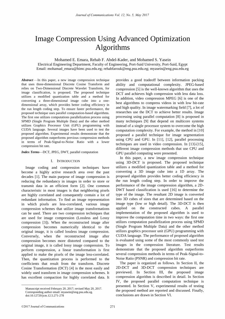
Image Compression Using Advanced Optimization
Algorithms
Mohamed E. Emara, Rehab F. Abdel-Kader, and Mohamed S. Yasein Electrical Engineering Department, Faculty of Engineering, Port-Said University, Port-Said, Egypt
Email: [email protected]; [email protected]; [email protected]
Abstract—In this paper, a new image compression technique
that uses three-dimensional Discrete Cosine Transform and
relies on Two-Dimensional Discrete Wavelet Transform, for
image classification, is proposed. The proposed technique
utilizes a modified quantization table and a method for
converting a three-dimensional image cube into a one-
dimensional array, which provides better coding efficiency in
the run length coding step. To ensure faster performance, the
proposed technique uses parallel computation-based algorithms.
The first one utilizes computations parallelization process using
SPMD (Single Program Multiple Data) and the other method
utilizes Graphics Processor Unit (GPU) programming with
CUDA language. Several images have been used to test the
proposed algorithm. Experimental results demonstrate that the
proposed algorithm outperforms previous compression methods
in terms of Peak-Signal-to-Noise Ratio with a lower
compression bit rate. Index Terms—DCT, JPEG, DWT, parallel computation
I. INTRODUCTION
Image coding and compression techniques have
become a highly active research area over the past
decades [1]. The main purpose of image compression is
reducing the redundancy in images in order to store or
transmit data in an efficient form [2]. One common
characteristic in most images is that neighboring pixels
are highly correlated and consequently contain a lot of
redundant information. To find an image representation
in which pixels are less-correlated, various image
compression schemes that utilize image transformations
can be used. There are two compression techniques that
are used for image compression (Lossless and Lossy
compression [3]). When the reconstructed image after
compression becomes numerically identical to the
original image, it is called lossless image compression.
Conversely, when the reconstructed image after
compression becomes more distorted compared to the
original image, it is called lossy image compression. To
perform compression, a linear transformation is first
applied to make the pixels of the image less-correlated.
Then, the quantization process is performed to the
coefficients that result from the transform. Discrete
Cosine Transformation (DCT) [4] is the most easily and
widely used transform in image compression schemes. It
has excellent compaction for highly correlated data. It
Manuscript received February 20, 2017; revised May 20, 2017. Corresponding author email: [email protected].
doi:10.12720/jcm.12.5.271-278
provides a good tradeoff between information packing
ability and computational complexity. JPEG-based
compression [5] is the well-known algorithm that uses the
DCT and achieves high compression with less data loss.
In addition, video compression MPEG [6] is one of the
best algorithms to compress videos in with low bit-rate
and high quality. In image watermarking field [7], a lot of
researches use the DCT to achieve better results. Image
processing using parallel computation [8] is proposed in
many techniques [9] that depend on multicore systems
instead of a single processor system to overcome the high
computation complexity. For example, the method in [10]
proposed a parallel technique for image segmentation
using CPU and GPU. In [11], [12], parallel processing
techniques are used in video compression. In [13]-[15],
different image compression methods that use CPU and
GPU parallel computing were presented.
In this paper, a new image compression technique
using 3D-DCT is proposed. The proposed technique
utilizes a modified quantization table and a method for
converting a 3D image cube into a 1D array. The
proposed algorithm provides better coding efficiency in
the run length coding step. In order to improve the
performance of the image compression algorithm, a 2D-
DWT based classification is used [16] to determine the
type of the image. The resultant 2D image is converted
into 3D cubes of sizes that are determined based on the
image type (low or high detail). The 3D-DCT is then
applied on the constructed cubes. A parallel
implementation of the proposed algorithm is used to
improve the computation time in two ways: the first one
utilizes computation parallelization process using SPMD
(Single Program Multiple Data) and the other method
utilizes graphics processor unit (GPU) programming with
CUDA language. The performance of proposed algorithm
is evaluated using some of the most commonly used test
images in the compression literature. Test results
demonstrate that the proposed algorithm outperforms
several compression methods in terms of Peak-Signal-to-
Noise Ratio (PSNR) and compression bit rate.
The paper is organized as follows. In Section II, the
2D-DCT and 3D-DCT compression techniques are
previewed. In Section III, the proposed image
compression algorithm is described in detail. In Section
IV, the proposed parallel computation technique is
presented. In Section V, experimental results of testing
the proposed method are reported and discussed. Finally,
conclusions are drawn in Section VI.
271
Journal of Communications Vol. 12, No. 5, May 2017
©2017 Journal of Communications

II. 3D-DCT BASED TECHNIQUES
3D-DCT has been used in many techniques. Some of
these techniques focus on integral images [17], [18],
where image elements are placed along the third
dimension before applying the 3D-DCT. This is
commonly used in video compression [19], [20], in which,
the temporal domain is used as the third dimension.
In visual tracking [21], 3D-DCT is frequently used to
represent the object appearance model that is robust to
variations in illumination, pose, etc. Furthermore, 3D-
DCT is used in many image processing applications, such
as video watermarking, denoising, and fingerprinting [22],
[24]. 3D-DCT sequential coding is used for specific
classes of images like medical images [25]. In [26], 3D
spiral JPEG image compression is used, where it uses
spiral scanning to format the multi-dimensional
constellation, in order to get a more effective
compression scheme [27]. For hyperspectral space
images, different techniques are proposed, as in [28], [29].
In video compression, 3D-DCT is used by taking the
two-dimensional frames and the temporal dimension (the
sequence of frames) as the basis. DCT coefficients can be
determined as:
1 1 1
0 0 0
( , ) ( ) ( ) ( ) ( , , )N M L
ux vy pz
x y z
F u v C u C v C p K f x y z A A A
(1)
where ijA and K are determined as
(2 1)
cos2
ij
j iA
N
(2)
8K
MxNxL (3)
and x = 0,1, ..., N−1; y M L−1; C(u)
and C(v) are determined as
2
0( ) 2
1
ifC
otherwise
(4)
III. THE PROPOSED IMAGE COMPRESSION ALGORITHM
The main goal of the proposed compression algorithm
is to achieve a high compression ratio with minimum
information loss. In the following subsections, the main
steps of the proposed 3D-DCT based compression
technique are described.
A. 3D Cube Formation
A 2D input image is first mapped into a set of 3D data
cubes. This is done by grouping NxN blocks. These
blocks are processed from left-to-right and top-to-bottom.
Eight NxN blocks are used to construct a 3D data cube.
In our technique, we used two cube-dimensions: 8x8x8
cubes and 4x4x4 cubes, depending on the image
classification which is determined as discussed in the
following sub-section.
B. Image Classification
When the correlation between the pixels (The
similarity between blocks [30]) is high, DCT coefficients
get smaller and, consequently, it yields a better
compression. Images can be classified into two types:
high-detail and low-detail images. The similarity ratio in
the low-detail images is more than that in high–detail
images. Based on that, we suggest that the 8x8x8 cube
size would be more suitable for low details images
because it has high similarity ratio, while the 4x4x4 cube
size would be more suitable for the high details images
because of its low similarity ratio.
In the proposed algorithm, an image classifier is used
to determine the type of the image. Such image classifier
decreases the dimension of the image by using Discrete
Wavelet Transform (DWT) and then uses the details
images to determine its type and to decide the appropriate
cube size. The result of 2D-DWT is decomposed into
four quadrants:
LL: The upper left quadrant represents the
approximated version of the original at half the resolution.
HL/LH: The lower left and the upper right blocks. The
LH block contains the vertical edges. In contrast, the HL
blocks shows the horizontal edges.
HH: The lower right quadrant. We can interpret this
block as the area where we find diagonal edges of the
original image.
The GxG image (512 x512 or any other size) is
decomposed by 1-level 2D-DWT, then take the inverse
DWT with only the LH sub-band (it is chosen
experimentally based on the vertical edges of image) and
the other sub bands are set to zero. We take the 2D-DFT
(Discrete Fourier Transform) [31] to compute the mean
of the inversed image. The computed mean is compared
to a certain threshold T (decided experimentally). If it is
lower than T, then the image is a low detail image.
Otherwise it is a high detail image. The block diagram for
this stage is shown in Fig. 1.
Fig. 1. Block diagram of the 2D-DWT based classifier
272
Journal of Communications Vol. 12, No. 5, May 2017
©2017 Journal of Communications
= 0,1,..., −1; z = 0,1,...,

C. 3D-DCT Transformation
The 3D-DCT, using eqn. (1), is performed on each
cube.
D. 3D Quantization
The quantization matrix that is used is MxMxM matrix
and can be determined by
zyxzyxQ 163),,( (5)
where x = 0, 1, ..., M−1, y = 0, 1, ..., M−1, and z = 0,
1,...,M−1.
Although it is not optimized, based on our experiments
this formula has provided the best results. The proposed
quantization table can be multiplied by a scalar to get
varying levels of compression rates and picture quality.
E. 3D Zig-Zag Scanning
It is necessary to convert a 3D cube into a 1D vector
before the variable length Huffman coding is applied. The
3D scan for 8x8x8 cube can be performed using four
techniques: (3D-Zig-Zag, 3D-Horizontal, 3D-Vertical
and 3D-Hilbert Scanning) as illustrated in Fig. 2.
Fig. 2. 3D Zig-Zag scanning
F. Huffman Encoding
Fig. 3. Encoder and decoder block diagram.
Huffman coding is combined with reducing the image
redundancy using DCT to help in compressing the image
data to a better level. The block diagram for the full
proposed system is shown in Fig. 3.
IV. THE PROPOSED PARALLEL COMPUTATION TECHNIQUE
In this paper, we used two methods for computations
parallelization:
A. SPMD (Single Program Multiple Data)
The main idea of SPMD technique depend on that we
have one block code and have several data that is used by
that code. In the SPMD technique, there are number of
workers that would be defined. So, by running identical
code on all workers, each worker can have different,
unique data for that code.
This proposed image compression using SPMD is
performed as in the following steps:
1- Divide the original image blocks into four sub-
images.
2- The proposed image compression algorithm
(Single Code) is run on the four sub-images
simultaneously in parallel.
3- The four decompressed sub-images are
reassembled in the final decompressed image.
The block diagram for the proposed system using
SPMD is shown in Fig. 4.
Fig. 4. Block diagram of the proposed image compression using SPMD.
B. CUDA Parallel Processing
Graphics Processor Unit (GPU) programming with
CUDA language can be utilized in the computations
parallelization process.
Using NVIDIA GPU) the CUDA programming
language re-define some phases of MATLAB code into
C-like language to re-evaluate it into parallelization
process. The improvement of the proposed image
compression algorithm consumption time is evaluated in
the experimental result.
1) 3D cube formation parallelization
In the 3D Cube formation code, there are a high
number of iteration (for-loops). Each iteration creates one
cube of NxNxN blocks, so we parallelize these iterations
in threads as shown in Fig. 5.
273
Journal of Communications Vol. 12, No. 5, May 2017
©2017 Journal of Communications
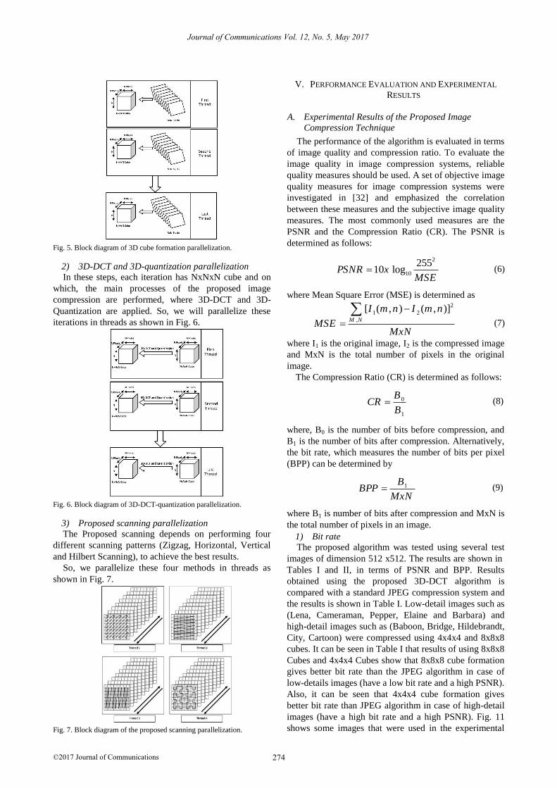
Fig. 5. Block diagram of 3D cube formation parallelization.
2) 3D-DCT and 3D-quantization parallelization
In these steps, each iteration has NxNxN cube and on
which, the main processes of the proposed image
compression are performed, where 3D-DCT and 3D-
Quantization are applied. So, we will parallelize these
iterations in threads as shown in Fig. 6.
Fig. 6. Block diagram of 3D-DCT-quantization parallelization.
3) Proposed scanning parallelization
The Proposed scanning depends on performing four
different scanning patterns (Zigzag, Horizontal, Vertical
and Hilbert Scanning), to achieve the best results.
So, we parallelize these four methods in threads as
shown in Fig. 7.
Fig. 7. Block diagram of the proposed scanning parallelization.
V. PERFORMANCE EVALUATION AND EXPERIMENTAL
RESULTS
A. Experimental Results of the Proposed Image
Compression Technique
The performance of the algorithm is evaluated in terms
of image quality and compression ratio. To evaluate the
image quality in image compression systems, reliable
quality measures should be used. A set of objective image
quality measures for image compression systems were
investigated in [32] and emphasized the correlation
between these measures and the subjective image quality
measures. The most commonly used measures are the
PSNR and the Compression Ratio (CR). The PSNR is
determined as follows:
2
10
25510 logPSNR x
MSE (6)
where Mean Square Error (MSE) is determined as 2
1 2
,
[ ( , ) ( , )]M N
I m n I m n
MSEMxN
(7)
where I1 is the original image, I2 is the compressed image
and MxN is the total number of pixels in the original
image.
The Compression Ratio (CR) is determined as follows:
0
1
BCR
B (8)
where, B0 is the number of bits before compression, and
B1 is the number of bits after compression. Alternatively,
the bit rate, which measures the number of bits per pixel
(BPP) can be determined by
1BBPP
MxN (9)
where B1 is number of bits after compression and MxN is
the total number of pixels in an image.
1) Bit rate
The proposed algorithm was tested using several test
images of dimension 512 x512. The results are shown in
Tables I and II, in terms of PSNR and BPP. Results
obtained using the proposed 3D-DCT algorithm is
compared with a standard JPEG compression system and
the results is shown in Table I. Low-detail images such as
(Lena, Cameraman, Pepper, Elaine and Barbara) and
high-detail images such as (Baboon, Bridge, Hildebrandt,
City, Cartoon) were compressed using 4x4x4 and 8x8x8
cubes. It can be seen in Table I that results of using 8x8x8
Cubes and 4x4x4 Cubes show that 8x8x8 cube formation
gives better bit rate than the JPEG algorithm in case of
low-details images (have a low bit rate and a high PSNR).
Also, it can be seen that 4x4x4 cube formation gives
better bit rate than JPEG algorithm in case of high-detail
images (have a high bit rate and a high PSNR). Fig. 11
shows some images that were used in the experimental
274
Journal of Communications Vol. 12, No. 5, May 2017
©2017 Journal of Communications
275
Journal of Communications Vol. 12, No. 5, May 2017
©2017 Journal of Communications
testing for different PSNRs. Lena and Baboon images
were selected as examples for low and high-detail images
and tested with different PSNR values and the results are
shown in Fig. 8 and Fig. 9.
Fig. 8. PSNR vs BPP in Lena image.
Fig. 9. PSNR vs BPP in baboon image
In Fig. 8, it can be noticed that the bit rate improves
with high PSNR in case of 8x8x8 cube. While, in Fig. 9,
it can be shown that the bit rate improves for high PSNR
in case of the 4x4x4 cube formation. Table II shows a
comparison of the results obtained using the proposed
3D-DCT algorithm, JPEG standard algorithm, and the
Spiral JPEG algorithm.
TABLE I: COMPARISON BETWEEN JPEG-BASED METHOD AND THE
PROPOSED 3D-DCT ALGORITHM (USING 8X8X8 AND 4X4X4 CUBE SIZE).
4x4x4
Cube
(BPP)
8x8x8
Cube
(BPP)
JPEG (BPP)
JPEG (BPP)
Low
/High N=8 or
N=4
Image
0.24 0.21 0.22 30
N=8 Lena 0.13 0.11 0.165 27
0.11 0.085 0.151 26
0.21 0.18 0.20 30
N=8 Cameraman 0.13 0.10 0.15 27
0.09 0.06 0.14 25
2.50 2.59 2.79 35
N=4 Baboon 2.11 2.17 2.32 33
1.52 1.56 1.63 30
1.14 1.16 1.18 28
2.78 2.87 3 37
N=4 Bridge 2.39 2.48 2.57 35
1.81 1.84 1.87 32
Quantization equation that used in the proposed
algorithm is derived to deal with cube formation method,
by changing the quantization equation that used in the
3D-Spiral compression algorithm and using the proposed
quantization equation. From Table II, it can be noticed
that 8x8x8 cube formation have slightly better bit rate
than 3D-Spiral JPEG algorithms, in the case of low-
details images like Lena and Flower. Furthermore, it can
be seen that 4x4x4 cube formation have slightly better bit
rate than the 3D-Spiral JPEG algorithm, in case of high-
details images, like Baboon.
TABLE II: COMPARISON BETWEEN JPEG, 3D-SPIRAL JPEG, AND 3D-
DCT USING TWO SIZES FOR CUBES.
4x4x4 Cube
(BPP)
8x8x8 Cube
(BPP)
Spiral
(BPP)
JPEG
(BPP) PSNR Image
0.153 0.128 0.13 0.17 27.65 Lena
3.05 3.10 3.13 3.38 37.68 Baboon
0.046 0.036 0.04 0.127 29,73 Flower
0.16 0.11 0.11 0.17 24.41 House
2) Time comparison
In terms of time, when using the two methods, we
observed that the compression system with 8x8x8 cube
formation is faster than the compression system with
4x4x4 cube formation and this is due to the large size of
blocks that used in the formation of the cube, the larger
the number of cubes, the less time the compression
process. And it also proved by results for different images,
as shown in Fig. 10.
02468
101214161820
1 at
PSNR o
f 36
2 at
PSNR o
f 38
3 at
PSNR o
f 39
4 at
PSNR o
f 33
5 at
PSNR o
f 34
6 at
PSNR o
f 30
7 at
PSNR o
f 30
8 at
PSNR o
f 31
9 at
PSNR o
f 32
10 a
t PSNR o
f 33
Images
Tim
e i
n s
eco
nd
s
8x8x8 Cube 4x4x4 Cube
Fig. 10. Time comparison for different images using the proposed two ways of compression
(a)
276
Journal of Communications Vol. 12, No. 5, May 2017
©2017 Journal of Communications
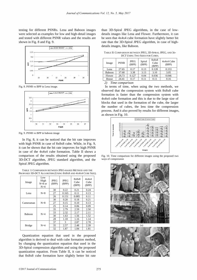
(b)
Fig. 11. (a) Original images (Pepper, Elaine, Bridge, City), (b)
Decompressed images (Pepper at PSNR=33.7 dB, Elaine at PSNR=
32.4 dB, Bridge at PSNR= 31.2 dB, City at PSNR=30.6).
3) Blocking artifact effects
Because of compression, the decompressed images
may exhibit various kinds of distortion artifacts such as
blocking, blurring and ringing [33]. The human visual
sensitivity to several types of artifacts is very different.
The blocking artifacts are usually the most significant
among them, especially at low bit rate compression. The
reduced blocking artifact effect in the proposed algorithm
can be illustrated in Fig. 12.
(a) Lena (Proposed) (b) Lena (JPEG)
(c) Cameraman (Proposed) (d) Cameraman (JPEG)
Fig. 12. Comparisons of the resulting compression artifacts: (a)
Proposed method using Lena (PSNR=27 for 0.11bpp), (b) JPEG method using Lena (PSNR=27 for 0.165bpp), (c) Proposed method using
Cameraman (PSNR=30 for 0.18bpp), (d) JPEG method using
Cameraman (PSNR=30 for 0.20bpp).
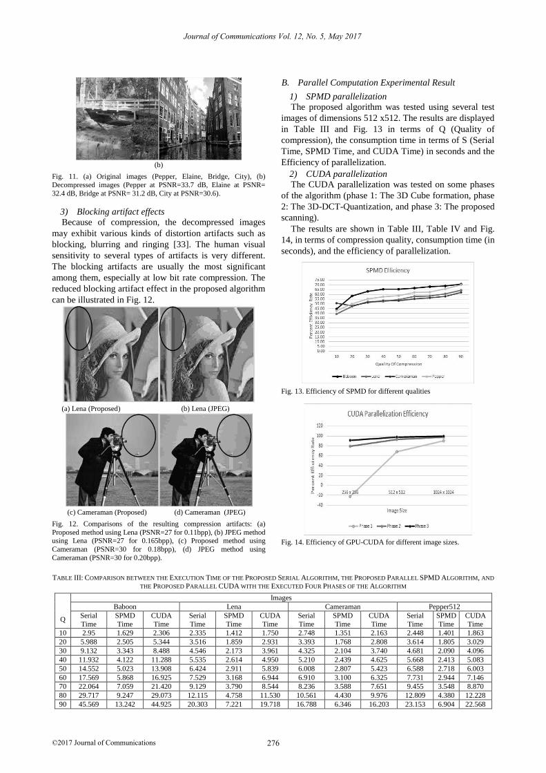
B. Parallel Computation Experimental Result
1) SPMD parallelization
The proposed algorithm was tested using several test
images of dimensions 512 x512. The results are displayed
in Table III and Fig. 13 in terms of Q (Quality of
compression), the consumption time in terms of S (Serial
Time, SPMD Time, and CUDA Time) in seconds and the
Efficiency of parallelization.
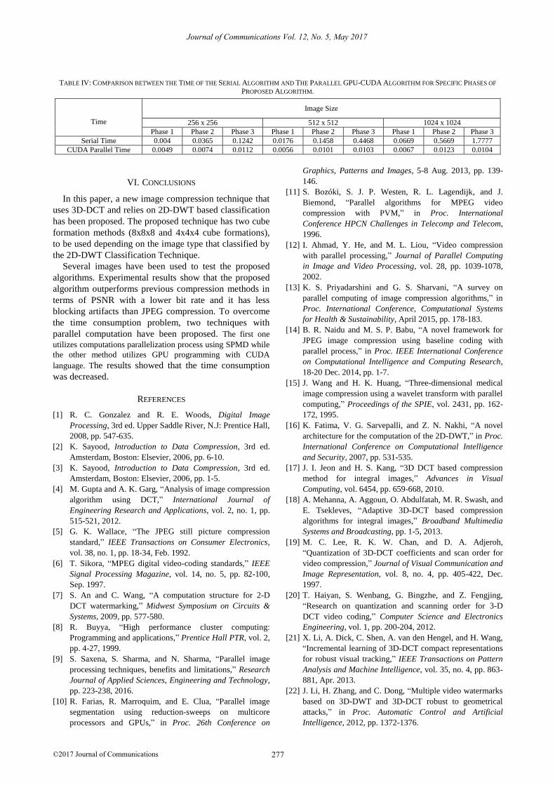
2) CUDA parallelization
The CUDA parallelization was tested on some phases
of the algorithm (phase 1: The 3D Cube formation, phase
2: The 3D-DCT-Quantization, and phase 3: The proposed
scanning).
The results are shown in Table III, Table IV and Fig.
14, in terms of compression quality, consumption time (in
seconds), and the efficiency of parallelization.
Fig. 13. Efficiency of SPMD for different qualities
Fig. 14. Efficiency of GPU-CUDA for different image sizes.
TABLE III: COMPARISON BETWEEN THE EXECUTION TIME OF THE PROPOSED SERIAL ALGORITHM, THE PROPOSED PARALLEL SPMD ALGORITHM, AND
THE PROPOSED PARALLEL CUDA WITH THE EXECUTED FOUR PHASES OF THE ALGORITHM
Q
Images
Baboon Lena Cameraman Pepper512
Serial
Time
SPMD
Time
CUDA
Time
Serial
Time
SPMD
Time
CUDA
Time
Serial
Time
SPMD
Time
CUDA
Time
Serial
Time
SPMD
Time
CUDA
Time
10 2.95 1.629 2.306 2.335 1.412 1.750 2.748 1.351 2.163 2.448 1.401 1.863
20 5.988 2.505 5.344 3.516 1.859 2.931 3.393 1.768 2.808 3.614 1.805 3.029
30 9.132 3.343 8.488 4.546 2.173 3.961 4.325 2.104 3.740 4.681 2.090 4.096
40 11.932 4.122 11.288 5.535 2.614 4.950 5.210 2.439 4.625 5.668 2.413 5.083
50 14.552 5.023 13.908 6.424 2.911 5.839 6.008 2.807 5.423 6.588 2.718 6.003
60 17.569 5.868 16.925 7.529 3.168 6.944 6.910 3.100 6.325 7.731 2.944 7.146
70 22.064 7.059 21.420 9.129 3.790 8.544 8.236 3.588 7.651 9.455 3.548 8.870
80 29.717 9.247 29.073 12.115 4.758 11.530 10.561 4.430 9.976 12.809 4.380 12.228
90 45.569 13.242 44.925 20.303 7.221 19.718 16.788 6.346 16.203 23.153 6.904 22.568
277
Journal of Communications Vol. 12, No. 5, May 2017
©2017 Journal of Communications
TABLE IV: COMPARISON BETWEEN THE TIME OF THE SERIAL ALGORITHM AND THE PARALLEL GPU-CUDA ALGORITHM FOR SPECIFIC PHASES OF
PROPOSED ALGORITHM.
Time
Image Size
256 x 256 512 x 512 1024 x 1024
Phase 1 Phase 2 Phase 3 Phase 1 Phase 2 Phase 3 Phase 1 Phase 2 Phase 3
Serial Time 0.004 0.0365 0.1242 0.0176 0.1458 0.4468 0.0669 0.5669 1.7777
CUDA Parallel Time 0.0049 0.0074 0.0112 0.0056 0.0101 0.0103 0.0067 0.0123 0.0104
VI. CONCLUSIONS
In this paper, a new image compression technique that
uses 3D-DCT and relies on 2D-DWT based classification
has been proposed. The proposed technique has two cube
formation methods (8x8x8 and 4x4x4 cube formations),
to be used depending on the image type that classified by
the 2D-DWT Classification Technique.
Several images have been used to test the proposed
algorithms. Experimental results show that the proposed
algorithm outperforms previous compression methods in
terms of PSNR with a lower bit rate and it has less
blocking artifacts than JPEG compression. To overcome
the time consumption problem, two techniques with
parallel computation have been proposed. The first one
utilizes computations parallelization process using SPMD while
the other method utilizes GPU programming with CUDA
language. The results showed that the time consumption
was decreased.
REFERENCES
[1] R. C. Gonzalez and R. E. Woods, Digital Image
Processing, 3rd ed. Upper Saddle River, N.J: Prentice Hall,
2008, pp. 547-635.
[2] K. Sayood, Introduction to Data Compression, 3rd ed.
Amsterdam, Boston: Elsevier, 2006, pp. 6-10.
[3] K. Sayood, Introduction to Data Compression, 3rd ed.
Amsterdam, Boston: Elsevier, 2006, pp. 1-5.
[4] M. Gupta and A. K. Garg, “Analysis of image compression
algorithm using DCT,” International Journal of
Engineering Research and Applications, vol. 2, no. 1, pp.
515-521, 2012.
[5] G. K. Wallace, “The JPEG still picture compression
standard,” IEEE Transactions on Consumer Electronics,
vol. 38, no. 1, pp. 18-34, Feb. 1992.
[6] T. Sikora, “MPEG digital video-coding standards,” IEEE
Signal Processing Magazine, vol. 14, no. 5, pp. 82-100,
Sep. 1997.
[7] S. An and C. Wang, “A computation structure for 2-D
DCT watermarking,” Midwest Symposium on Circuits &
Systems, 2009, pp. 577-580.
[8] R. Buyya, “High performance cluster computing:
Programming and applications,” Prentice Hall PTR, vol. 2,
pp. 4-27, 1999.
[9] S. Saxena, S. Sharma, and N. Sharma, “Parallel image
processing techniques, benefits and limitations,” Research
Journal of Applied Sciences, Engineering and Technology,
pp. 223-238, 2016.
[10] R. Farias, R. Marroquim, and E. Clua, “Parallel image
segmentation using reduction-sweeps on multicore
processors and GPUs,” in Proc. 26th Conference on
Graphics, Patterns and Images, 5-8 Aug. 2013, pp. 139-
146.
[11] S. Bozóki, S. J. P. Westen, R. L. Lagendijk, and J.
Biemond, “Parallel algorithms for MPEG video
compression with PVM,” in Proc. International
Conference HPCN Challenges in Telecomp and Telecom,
1996.
[12] I. Ahmad, Y. He, and M. L. Liou, “Video compression
with parallel processing,” Journal of Parallel Computing
in Image and Video Processing, vol. 28, pp. 1039-1078,
2002.
[13] K. S. Priyadarshini and G. S. Sharvani, “A survey on
parallel computing of image compression algorithms,” in
Proc. International Conference, Computational Systems
for Health & Sustainability, April 2015, pp. 178-183.
[14] B. R. Naidu and M. S. P. Babu, “A novel framework for
JPEG image compression using baseline coding with
parallel process,” in Proc. IEEE International Conference
on Computational Intelligence and Computing Research,
18-20 Dec. 2014, pp. 1-7.
[15] J. Wang and H. K. Huang, “Three-dimensional medical
image compression using a wavelet transform with parallel
computing,” Proceedings of the SPIE, vol. 2431, pp. 162-
172, 1995.
[16] K. Fatima, V. G. Sarvepalli, and Z. N. Nakhi, “A novel
architecture for the computation of the 2D-DWT,” in Proc.
International Conference on Computational Intelligence
and Security, 2007, pp. 531-535.
[17] J. I. Jeon and H. S. Kang, “3D DCT based compression
method for integral images,” Advances in Visual
Computing, vol. 6454, pp. 659-668, 2010.
[18] A. Mehanna, A. Aggoun, O. Abdulfatah, M. R. Swash, and
E. Tsekleves, “Adaptive 3D-DCT based compression
algorithms for integral images,” Broadband Multimedia
Systems and Broadcasting, pp. 1-5, 2013.
[19] M. C. Lee, R. K. W. Chan, and D. A. Adjeroh,
“Quantization of 3D-DCT coefficients and scan order for
video compression,” Journal of Visual Communication and
Image Representation, vol. 8, no. 4, pp. 405-422, Dec.
1997.
[20] T. Haiyan, S. Wenbang, G. Bingzhe, and Z. Fengjing,
“Research on quantization and scanning order for 3-D
DCT video coding,” Computer Science and Electronics
Engineering, vol. 1, pp. 200-204, 2012.
[21] X. Li, A. Dick, C. Shen, A. van den Hengel, and H. Wang,
“Incremental learning of 3D-DCT compact representations
for robust visual tracking,” IEEE Transactions on Pattern
Analysis and Machine Intelligence, vol. 35, no. 4, pp. 863-
881, Apr. 2013.
[22] J. Li, H. Zhang, and C. Dong, “Multiple video watermarks
based on 3D-DWT and 3D-DCT robust to geometrical
attacks,” in Proc. Automatic Control and Artificial
Intelligence, 2012, pp. 1372-1376.
278
Journal of Communications Vol. 12, No. 5, May 2017
©2017 Journal of Communications
[23] M. Joachimiak, D. Rusanovskyy, M. M. Hannuksela, and
G. M. Multiview, “3D video denoising in sliding 3D DCT
domain,” in Proc. 20th European Signal Processing
Conference, 2012.
[24] H. Mao, G. Feng, X. Zhang, and H. Yao, “A robust and
fast video fingerprinting based on 3D-DCT and LSH,” in
Proc. International Conference on Multimedia Technology,
2011, pp. 108-111.
[25] X. Li and B. Furht, “An approach to image and video
compression using three-dimensional DCT,” in Proc.
Visual 2003 Conference, Miami, Florida, September 2003.
[26] M. A. Engin and B. Cavusoglu, “New approach in image
compression: 3D Spiral JPEG,” IEEE Communications
Letters, vol. 15, no. 11, pp. 1234-1236, Nov. 2011.
[27] L. Blaszak and M. Domanski, “Spiral coding order of
macroblocks with applications to SNR-scalable video
compression,” in Proc. International Conference on Image
Processing, vol. 3, pp. III-688, 2005.
[28] A. Mulla, J. Baviskar, A. Baviskar, and C. Warty, “Image
compression scheme based on zig-zag 3D-DCT and LDPC
coding,” in Proc. International Conference on Advances in
Computing, Communications and Informatics, 2014, pp.
2380-2384.
[29] A. Karami, S. Beheshti, and M. Yazdi, “Hyperspectral
image compression using 3D discrete cosine transform and
support vector machine learning,” in Proc. International
Conference on Information Science, Signal Processing and
their Applications, 2012, pp. 809-812.
[30] H. Palangi, A. Ghafari, M. Babaie-Zadeh, and C. Jutten,
“Image coding and compression with sparse 3D discrete
cosine transform,” in Independent Component Analysis
and Signal Separation, vol. 5441, T. Adali, C. Jutten, J. M.
T. Romano, and A. K. Barros, Eds., Berlin, Heidelberg:
Springer Berlin Heidelberg, 2009, pp. 532-539.
[31] R. C. Gonzalez and R. E. Woods, Digital Image
Processing, 3rd ed. Upper Saddle River, N.J: Prentice Hall,
2008, pp. 247-275.
[32] M. Mrak, S. Grgic, and M. Grgic, “Picture quality
measures in image compression systems,” EUROCON, vol.
1, pp. 233-236, 2003.
[33] L. Li, W. Lin, and H. Zhu, “Learning structural regularity
for evaluating blocking artifacts in JPEG images,” IEEE
Signal Processing Letters, vol. 21, no. 8, pp. 918-922, Aug.
2014.
Mohamed E. Emara was born in Port
Said, Egypt, in 1990. He graduated from
the Faculty of Engineering-Port Said
University in 2012 and joined
postgraduate studies to obtain a master's
degree in Engineering Science. His
research interests include image
processing, and information theory.
Rehab Farouk Abdel-Kader attended
Suez Canal University, Egypt majoring
in Computer Engineering, earning the
BS degree in 1996. She graduated from
Tuskegee University, with a MS degree
in Electrical Engineering in 1999. She
joined the Ph.D. program at Auburn
University and earned her Doctor of
Philosophy degree in 2003. She worked as an assistant
Professor in the Engineering Studies Program in Georgia
Southern University, Statesboro, Georgia from 2003 to 2005.
She is currently an Associate professor in the Electrical
Engineering department, Faculty of Engineering at Port-Said,
Port-Said University, Port-Said, Egypt. Her current research
interests include Artificial Intelligence, and Computer Vision.
Mohamed Seddeik Yasein attended
Suez Canal University, Egypt, in
Computer Engineering and earned the
BS degree in 1996. He received the MSc
and PhD degrees in electrical &
computer engineering from the
University of Victoria, BC Canada, in
2002 and 2008, respectively. He was an
assistant professor in the department of computer science, Suez
Canal University, Ismalia, Egypt in 2008- 2011 and joined the
department of electrical & computer engineering, Port Said
University, Egypt in 2011- 2014. He is currently an assistant
professor in Umm Al-Qura University, KSA. His research
interests include digital signal processing, image matching and
registration, and modeling and simulation systems.