image ii - construction
TRANSCRIPT

IMAGE IIMETAL ROOFINGInstallation Guide

© Metal Sales Manufacturing Corporation / Subject to change without notice, effective 6/2011�
Important Information The application and detail drawings in this manual are strictly for illustration purposes and may not be applicable to all building designs or product installa-tions. All projects should conform to applicable build-ing codes for that particular area. Metal Sales Manufacturing Corporation is not responsible for the performance of the metal panel system if it is not installed in accordance with the sug-gested instructions referenced in this manual. If there is a conflict between this manual and the approved Metal Sales' erection drawings, the approved erection drawings are to take precedence. Prior to ordering and installing materials, all dimen-sions should be verified by field measurements. Oil canning is not a cause for rejection. Metal Sales reserves the right to modify, without notice, any details, recommendations or suggestions. This manual is designed to be utilized as a guide when installing a Image II Roof System.

© Metal Sales Manufacturing Corporation / Subject to change without notice, effective 6/2011�
Table of ContentsImportant Information ............................................................ 1Panel Information .................................................................... 3Handling Material .................................................................... 4Delivery & Storage ................................................................... 4Safety Considerations .............................................................. 5Panel Conditions ...................................................................6-7Slope Data ................................................................................. 8
Flashings ..............................................................................9-11Eave ........................................................................................... 9Extended Eave .......................................................................... 9Cleat .......................................................................................... 9Offset Cleat ............................................................................... 912" Coil ...................................................................................... 9Valley ....................................................................................... 10Image II Rake ......................................................................... 10Image II Step Rake ................................................................ 10Rakewall.................................................................................. 10Image II Step Rakewall ......................................................... 10Counter Flashing .................................................................... 10Reglet Flashing ....................................................................... 10Step Ridge/Hip Cover ............................................................ 1013" Ridge/Hip Cover .............................................................. 10Perforated Vent Drip ............................................................. 10Peak ......................................................................................... 11Pitch Break ............................................................................. 111.5" Sill/Head .......................................................................... 111.5" Sill To Soffit ..................................................................... 111" Z-Closure ............................................................................ 11
Accessories .............................................................................. 12Fastener Selection & Installation.......................................... 13Fastening Guide ................................................................14-15Eave Installation..................................................................... 16Valley Installation .................................................................. 17Panel Installation (Exposed) ............................................18-19Panel Installation (Concealed) .........................................20-22
Details .................................................................................23-33Eave ......................................................................................... 23Gutter ...................................................................................... 24Valley ....................................................................................... 25Rake ......................................................................................... 26Rakewall with Counter .......................................................... 27Rakewall with Reglet ............................................................. 28Endwall with Counter ............................................................ 29Endwall with Reglet ............................................................... 30Slope Change .......................................................................... 31Peak ......................................................................................... 31Ridge/Hip ................................................................................ 32Vented Ridge ........................................................................... 321" Z-Closure Installation ....................................................... 33
Final Instructions ................................................................... 34Section Properties .................................................................. 35Notes ...................................................................................36-39

© Metal Sales Manufacturing Corporation / Subject to change without notice, effective 6/2011�
Panel Information
• Minimum recommended slope for Image II is 3:12• Recommended substrate is 5/8" plywood with 30# felt moisture barrier• Available in 12" and 16" widths with 1" rib height• Minimum panel length is 5'• Maximum panel length is 30'
Call a Metal Sales representative for more information.
C - Indicates colored side of panel
*West Coast refers to Image II panels manufactured at theWoodland, California and Anchorage, Alaska branches
Striated
12"Panel Coverage
C1"
1"C
12"Panel Coverage
With Minor Ribs(West Coast Only*)
16"Panel Coverage
1"C
Striated
16"Panel Coverage
1"C
With Minor Ribs(West Coast Only*)

© Metal Sales Manufacturing Corporation / Subject to change without notice, effective 6/2011�
Handling Material
CAUTIONImproper loading and unloading of bundles and
crates may result in bodily harm and/or material damage. Metal Sales is not responsible for
bodily injuries and/or material damages resulting from improper
loading and unloading.
General HandlingEach bundle should be handled carefully to avoid being damaged. Care should be taken to prevent bending of the panel or scratching the finish. When-ever possible, the bundle should remain crated until it is located in its place of storage. If bundles must be opened, we recommend you recrate them before lifting. To avoid damage please lift the bundle at its center of gravity.
Delivery & StorageAlways check the shipment upon delivery. Check for damage and check material quantities against the shipping list. Note any damaged material or shortages at the time of delivery and notify your supplier within 24 hours.Store the panels and other materials in a dry, well-ventilated area away from traffic. Elevate one end of the bundle, maximum 2', so that any moisture that may have accumulated during shipping can run off. Be sure that air will be able to circulate freely around the bundles to avoid the build-up of moisture. Never store materials in direct contact withthe ground.Some products may have a peel off plastic film over the painted surface. This film was factory applied to prevent damage to the finish that may occur during manufacturing or shipping. If this film is present, avoid exposure of the “peel-coated” parts to sunlight and remove the “peel-coat” prior to installation.Do not slide panels or accessories across one another.
•
•
•
•

© Metal Sales Manufacturing Corporation / Subject to change without notice, effective 6/2011�
Safety ConsiderationsSTUDY APPLICABLE OSHA AND OTHER STATE
AND FEDERAL SAFETY REQUIREMENTS BEFORE FOLLOWING THESE INSTRUCTIONS.
The installation of metal roofing systems is a dangerous procedure and should be supervised by trained, knowledgeable installers. USE EXTREME CARE WHILE INSTALLING ROOFING PANELS. The installer of the roofing system is responsible for reading these instructions and determining the safest way to install the roofing system.
Proper personal protective equipment may include, but is not limited to:
Hand Protection: Kevlar coated gloves to reduce risk of abrasion and laceration while handling productEye Protection: Approved safety glasses to protect against flying debris when handling or cutting productFall Protection: Never step on unsecured panels. Never work on a roof without protection from falls
Note: Other personal protective equipment may be required, including: hard hats, protective clothing, or a harness.
•
•
•

© Metal Sales Manufacturing Corporation / Subject to change without notice, effective 6/2011�
Map of Typical Conditions
1. Gutter (See Page 24) 2. Peak (See Page 31) 3. Endwall (See Pages 29-30) 4. Ridge/Vented Ridge (See Page 32) 5. Eave (See Pages 16, 23) 6. Hip (See Page 32) 7. Valley (See Pages 17, 25) 8. Rakewall (See Pages 27-28) 9. Rake (See Page 26)10. Slope Change (See Page 31)
1
2
3
5
4
10
Panel Conditions

© Metal Sales Manufacturing Corporation / Subject to change without notice, effective 6/2011�
The application and detail drawings that follow are strictly for illustration purposes and may not be applicable to all building designs or product installations. All projects should conform to appli-cable building codes for that particular area. It is recommended to follow all building regulations and standard industry practices. Metal Sales is not responsible for the per-formance of the metal panel system if it is not installed in accordance with the suggested instruc-tions referenced in this manual. If there is a con-flict between this manual and the approved Metal Sales erection drawings, the approved erection drawings are to take precedence.
6
7
8
9

© Metal Sales Manufacturing Corporation / Subject to change without notice, effective 6/2011�
This chart should be used when specifying and ordering panels and flashings. It will help you determine overall required length of material on sloped applications.
Your building is 28'-0'' wide with a 4:12 pitchTo determine the panel lengths for each side:
(L) X (SLOPE FACTOR) = S
14'-0'' x 1.0541(from chart above) = 14.7573' OR 14'-9''
Slope Data
1:12
SLOPE
2:123:124:125:126:12
SLOPEFACTOR
1.00351.01381.03081.05411.08331.1180
HIP / VALLEYMULTIPLIER
1.41671.42401.43621.45301.47431.5000
7:12
SLOPE
8:129:12
10:1211:1212:12
SLOPEFACTOR
1.15771.20191.25001.30171.35661.4142
HIP / VALLEYMULTIPLIER
1.52981.56351.60081.64151.68531.7320
EXAMPLE:
L
S
Eave
Peak
L H
Hip or ValleyRake
Eave or Gutter
��'-0''
��'-0''
Ridge
��'-0''
��'-0''
���
Slope

© Metal Sales Manufacturing Corporation / Subject to change without notice, effective 6/2011�
Standard Flashings
Eave
��/�"
�/�"
C
Open Hem
�"
X*
�0'-�'' Length* Specify Slope Angle
�"
�/�"
C
Open Hem
�"
X*
Extended Eave
Cleat Offset Cleat
�0'-�'' Length* Specify Slope Angle
�/�"C
��/�"
���°
�0'-�'' Length �0'-�'' Length
��/�"�"
C�/�"
��'' Coil(For continuous gutters)
��'' Inside Diameter
C - Indicates colored side of panel

© Metal Sales Manufacturing Corporation / Subject to change without notice, effective 6/2011�0
Standard Flashings (Cont.)Valley
�0"C
�"X*
�0'-�'' Length* Specify Slope Angle
�/�"
C
Image II Rake
Image II Step Rake Rakewall�0'-�'' or �0'-�'' Length
�/�"
C
��/�"
�0'-�'' or �0'-�'' Length �0'-�'' Length
��/�"
C
Image II Step Rakewall Counter Flashing
C
�0'-�'' Length
C
Reglet Flashing Step Ridge/Hip Cover
C
�0'-�'' Length
��” Ridge/Hip Cover Perforated Vent Drip
��/�"
�/�"
Open Hem
Hem ��/�"
Hem
��/�"
��/�"
�/�"�/�"
�/�"
�/�"
Hem
�0'-�'' Length
�/�"
��/�"C
X*
�0'-�'' Length* Specify Slope Angle
Hem
X*
C��/�"
�0'-�'' Length* Specify Slope Angle �0'-�'' Length
C ��/�"
���°�/�"
�"
�"�"
�"
�"
�"
�"
�"�"
��/�"
��/�"�/�"

© Metal Sales Manufacturing Corporation / Subject to change without notice, effective 6/2011��
Standard Flashings (Cont.)Peak
�"C
�" X*
�0'-�'' or �0'-�'' Length * Specify Slope Angle
C
Pitch Break
�.�” Sill/Head 1.5” Sill To Soffit
�/�"
C
��/�"
�0'-�'' Length �0'-�'' Length
�” Z-Closure
C
�0'-�'' Length
�"
�/�"
��/�"
�0'-�'' Length * Specify Slope Angle
X*
�"
C
��/�"�/�"
��/�"
��/�"
�/�"
�"
�"
�"
PROFILE/FLASHING 3:12 4:12 5:12 6:12 7:12
EAVE 104° 108° 113° 117° 120°
PEAK 76° 72° 67° 63° 60°
PITCH BREAK 104° 108° 113° 117° 120°
VALLEY,HIP 160° 154° 148° 143° 138°
RIDGE 152° 143° 135° 127° 120°

© Metal Sales Manufacturing Corporation / Subject to change without notice, effective 6/2011��
Accessories
��"
Cobra Vented Closure
Tube Sealant
Double Bead Tape Sealant�/�" x �/��" x ��'-0''
Butyl-Gray
Touch-Up PaintAvailable in pintsPVDF and CF��
Metal Panel Hemming Tool
Rubber Roof JackMINI (�/�" to ��/�" O.D. Pipe)#� (��/�" to �" O.D. Pipe)#� (�" to �" O.D. Pipe)#� (�" to �" O.D. Pipe)#� (�" to ��" O.D. Pipe)
Image II Outside Closure
��"
UnderlaymentPrimer
ms-HTPeel-and-StickUnderlayment
© Metal Sales Manufacturing Corporation / Subject to change without notice, effective 6/2011��
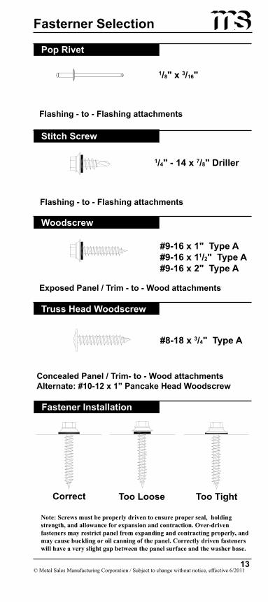
Fasterner Selection
Pop Rivet
Stitch Screw
Woodscrew
Truss Head Woodscrew
�/�" x �/��"
�/�" - �� x �/�" Driller
#�-�� x �" Type A#�-�� x ��/�" Type A#�-�� x �" Type A
Note: Screws must be properly driven to ensure proper seal, holding strength, and allowance for expansion and contraction. Over-driven fasteners may restrict panel from expanding and contracting properly, and may cause buckling or oil canning of the panel. Correctly driven fasteners will have a very slight gap between the panel surface and the washer base.
Fastener Installation
Correct Too Loose Too Tight
Concealed Panel / Trim- to - Wood attachmentsAlternate: #�0-�� x �” Pancake Head Woodscrew
Flashing - to - Flashing attachments
Flashing - to - Flashing attachments
Exposed Panel / Trim - to - Wood attachments
#�-�� x �/�" Type A

© Metal Sales Manufacturing Corporation / Subject to change without notice, effective 6/2011��
Zone 1 (Field)
Zone 3 (Corner)
Zone 2 (Edge)
aa
Fastening GuideRecommended Fastener Spacing (inches)
For Slopes �:�� to �:��
Wind Speed (mph)Exposure Category Roof Slope: 3:12 - 6:12
�0BField
-13.3 psfEdge
-23.2 psfCorner
-34.3 psf
�� �� ��
�0CField
-17.2 psfEdge
-29.9 psfCorner
-44.2 psf
�� �� ��
�00BField
-16.5 psfEdge
-29.9 psfCorner
-42.2 psf
�� �� ��
�00CField
-21.2 psfEdge
-36.9 psfCorner
-54.6 psf
�� �� ��
��0BField
-19.9 psfEdge
-34.7 psfCorner
-51.3 psf
�� �� ��
��0CField
-25.6 psfEdge
-44.6 psfCorner-66 psf
�� �� ��
��0BField
-23.7 psfEdge
-41.3 psfCorner-61 psf
�� �� ��
��0CField
-30.5 psfEdge
-53.1 psfCorner
-78.6 psf
�� �� �
Notes: Fastener spacing is based on #8-18 x 3/4" Truss Head Woodscrew fastener in the nail strip attaching to 5/8" plywood . 1/3 allowable stress increase is not used.Allowable spacing is based on an applied load determined using ASCE 7-05 for the Wind Speeds. Wind Exposure Categories, Roof area, Gable roof, Enclosed building, Topographic factor of 1, Importance factor of 1 and mean roof height of 20'.Allowable spacing is determined for wind suction using the combination 0.6 DL + WL. Also considered is the appropriate inward wind pressure, 20 psf live load and the weight of the panel.
1.
2.
3.
Contact Metal Sales for use of other types of fasteners and substrates.

© Metal Sales Manufacturing Corporation / Subject to change without notice, effective 6/2011��
Fastening Guide (Cont.)Recommended Fastener Spacing (inches)
For Slopes �:�� to ��:��
Wind Speed (mph)Exposure Category Roof Slope: 6:12 - 12:12
�0BField
-14.6 psfEdge
-17 psfCorner-17 psf
�� �� ��
�0CField
-18.8 psfEdge
-21.9 psfCorner
-21.9 psf
�� �� ��
�00BField
-18.8 psfEdge
-21.9 psfCorner-21 psf
�� �� ��
�00CField
-23.2 psfEdge
-27.1 psfCorner
-27.1 psf
�� �� ��
��0BField
-21.8 psfEdge-25.5
Corner-25.5
�� �� ��
��0CField
-28 psfEdge
-32.8 psfCorner
-32.8 psf
�� �� ��
��0BField
-25.9 psfEdge
-30.3 psfCorner
-30.3 psf
�� �� ��
��0CField
-33.3 psfEdge
-39 psfCorner-39 psf
�� �� ��
Zone 1 (Field)
Zone 3 (Corner)
Zone 2 (Edge)
aa
Notes: Fastener spacing is based on #8-18 x 3/4" Truss Head Woodscrew fastener in the nail strip attaching to 5/8" plywood . 1/3 allowable stress increase is not used.Allowable spacing is based on an applied load determined using ASCE 7-05 for the Wind Speeds. Wind Exposure Categories, Roof area, Gable roof, Enclosed building, Topographic factor of 1, Importance factor of 1 and mean roof height of 20'.Allowable spacing is determined for wind suction using the combination 0.6 DL + WL. Also considered is the appropriate inward wind pressure, 20 psf live load and the weight of the panel.
1.
2.
3.
Contact Metal Sales for use of other types of fasteners and substrates.

© Metal Sales Manufacturing Corporation / Subject to change without notice, effective 6/2011��
Installation Procedures
If your building requires a Gutter instead of Eave Flashing, please see page 22 for installation.Moisture Barrier must be installed prior to beginning installation. Metal Sales recommends a minimum 30# felt moisture barrier. To avoid panel distortion, use a properly aligned and uniform substructure.
All Cleat and Eave flashings must be installed prior to panel installation.
Position Cleat on wall at the appropriate distance from roof-line. Make sure Cleat allows for proper Eave attachment.Attach Cleat to wall with #8-18 x 3/4" Truss Head Woodscrews, 1' o.c.Install Eave flashing by inserting the open hem of the Eave flashing onto the bottom leg of the Cleat and rest the Eave flashing against the substrate.Fasten Eave flashing to substrate with #8-18 x 3/4" Truss Head Woodscrews, 4' o.c. to hold the Eave flashing in place during installation.
Note: If two or more flashings are required, lap the flashing over the previously installed flashingby a minimum of 2" placing 2 beads of Tube Sealant between the flashings and securing with Pop Rivets, 2" o.c.
1.
2.
3.
4.
Step �Installing Cleat & Eave Flashings
Moisture BarrierTruss Head Woodscrew,�' o.c. (�)Cleat (�)
�"*
Moisture Barrier
Eave (�)
Cleat (�)
Truss Head Woodscrew,�' o.c. (�)
Truss Head Woodscrew,�' o.c. (�)
* �" Dimension is based on the standard Eave Flashing (See page �) Dimension may vary with different flashings.
(X) Numbers indicate sequence of installation.

© Metal Sales Manufacturing Corporation / Subject to change without notice, effective 6/2011��
All Valley flashings must be installed prior to panel installation.
Position Valley on roof, working from the low end to the high end.Attach Valley to substrate with #8-18 x 3/4" Truss Head Woodscrews, 4' o.c.Make sure Truss Head Woodscrews are positioned as to be covered by the Image II Panel when installed.
Note: If two or more Valley flashings are required, lap the Valley flashing over the previously installed Valley flashing by a minimum of 6" placing 2 beads of Tube Sealant between the flashings.
1.
2.
3.
Step �Installing Valley Flashing
Moisture Barrier
Valley (�)
Truss Head Woodscrew,�' o.c. (�)
Installation Procedures
(X) Numbers indicate sequence of installation.

© Metal Sales Manufacturing Corporation / Subject to change without notice, effective 6/2011��
Step �Exposed Fastened Panel installation
Installing First Panel
Panel Installation
Apply a row of Double Bead Tape Sealant on the top leg of the Eave flashing.Install first panel so that the panel end has proper overhang making sure that panel is square to eave and rake. It is critical that the first panel be straight and square with the building as it controls alignment of the following roof panels.Fasten panel to substrate with a #8-18 x 3/4" Truss Head Wood-screw in center of the fastening groove located along the male leg of the panel. Fastener spacing must be designed to meet local building codes. It is important that the fastener be placed in the center of the fastening groove and make sure not to over tighten screws.Fasten Image II panel with (4) #9-16 x 1" Woodscrews through Double Bead Tape Sealant, flashing, and into the solid sub-strate as shown below.
1.
2.
3.
4.
Square panel at Rake (�)
Position panel at Eave (�)#�-�� x �" Woodscrew (�)
Double Bead Tape Sealant (�)
Truss HeadWoodscrew (�)
CAUTIONAdditional screws
may be required for high snow loading and steep slopes.
Image II Panel (�)
Double Bead Tape Sealant (�)#�-�� x �" Woodscrew
(X) Numbers indicate sequence of installation.

© Metal Sales Manufacturing Corporation / Subject to change without notice, effective 6/2011��
Panel Installation
Snap second panel in place making sure panel ends are aligned. Snap panel in place working from one end to the other.Fasten substrate with a #8-18 x 3/4" Truss Head Woodscrew in the center of the fastening groove located along the male leg of the panel. Fastener spacing must be designed to meet local building codes.Fasten Image II panel with (4) #9-16 x 1" Woodscrews through Double Bead Tape Sealant, flashing, and into the solid sub-strate below.Continue with previous step until installation is complete. It is important that the fastener is in the center of the fastening groove, and make sure not to over-tighten the screws.Once installation is complete, fill each lower end of panel rib with Tube Sealant, and clean any debris and excess sealant before continuing to next area.
1.
2.
3.
4.
5.
CAUTIONAdditional screws
may be required for high snow loading and steep slopes.
Position panel to keep ends flush (�)
#�-�� x �" Woodscrew (�)
Double Bead Tape Sealant (�)
Apply sealant at all rib ends along eave
(�)
Step �Exposed Fastened Panel Installation
Installing Second Panel
(X) Numbers indicate sequence of installation.

© Metal Sales Manufacturing Corporation / Subject to change without notice, effective 6/2011�0
Panel Installation
Note: Moisture Barriers, Eave, Valley, and Offset Cleat flashing must first be installed before panel installation can begin Image II panels are installed from left to right or right to left.
Install Eave flashing and Valley flashing as shown on pages 16-17.Apply a row of Double Bead Tape Sealant on the bottom leg of the Offset Cleat and align on substrate.Fasten Offset Cleat to substrate with a #8-18 x 3/4" Truss Head Woodscrew through top of Eave flashing and into substrate, 1' o.c. Make sure Offset Cleat is lined up to properly accomo-date hemmed panel.Field notch and hem the Image II panel as shown below.Apply a single bead of tube sealant inside the open hem of the Image II panel.
Note: If you are to field bend the panel ends to close off panels on the low side, see page 22 before field notching and hemming of the panels.
1.
2.
3.
4.5.
Double Bead Tape Sealant (�)Truss Head Woodscrew (�)
Offset Cleat (�)
Hemming DetailField Notch Rib (�)
��/�"
��/�"
Field bend flat partof panel to acceptOffset Cleat (�)
Hemming Tool
Field apply tube sealant in hem and slide ontopre-installed Offset Cleat (�)
Step �Concealed Fastened Panel Installation
Installing First Panel
Eave Flashing (�)
(X) Numbers indicate sequence of installation.

© Metal Sales Manufacturing Corporation / Subject to change without notice, effective 6/2011��
Panel InstallationStep � (cont)
Concealed Fastened Panel InstallationInstalling First Panel
Square panelat Rake (�)
Position panelat Eave (�)
Double Bead Tape Sealant
Truss HeadWoodscrew (�)
Install first panel so that eave has proper overhang making sure that the panel is square to eave and rake. Slide the panel toward the peak of the roof engaging the panel with the Offset Cleat. Offset Cleat must be fully engaged into the panel. Additional overhang must be considered if using wall panels. It is critical that the first panel be straight and square with the building as it controls alignment of the following roof panels.Fasten panel to substrate with a #8-18 x 3/4" Truss Head Woodscrew in the center of the fastening groove located along the male leg of the panel. Fastener spacing must be designed to meet local building codes. (It is important that the fastener be placed in the center of the fastening groove and make sure not to over-tighten screws.)
6.
7.
(X) Numbers indicate sequence of installation.

© Metal Sales Manufacturing Corporation / Subject to change without notice, effective 6/2011��
Field notch and hem the Image II panel as shown on page 20. Apply a single bead of Tube Sealant inside the open hem of the Image II panel.Place the second panel on top of previously installed panel so that the second hemmed panel can be engaged with the Offset Cleat.Begin snapping the panels together working from eave to peak. It is critical that panels only be snapped in one direction.Repeat notes 2 and 3 for remaining panels.Once installation is complete, fill each lower end of panel rib with sealant. Also, clean any debris and excess sealant. Panels may also be field notched and bent to close off panel end (See below).
1.
2.
3.
4.5.
Step �Concealed Fastened Panel Installation
Installing Second Panel
Panel Installation
Offset Cleat
Apply sealant at all rib ends along eave
(�)
Position panel to keepends flush (�)
��/�"
��/�"
��/�"
Field cut panel ribs
�/�"
Note: If you are to field bend the panel ends to close off panels on the low side, this must be done before hemming of panels (see page 20).
Pop Rivet (�)
(X) Numbers indicate sequence of installation.

© Metal Sales Manufacturing Corporation / Subject to change without notice, effective 6/2011��
Eave DetailAll Eave flashings must be installed prior to panel installation.
Position and install Cleat to wall with #8-18 x 3/4" Truss Head Woodscrew, 1' o.c. Make sure Cleat allows for proper Eave attachment considering wall panels.Install Eave flashing by resting the flashing against the substrate and fasten with #8-18 x 3/4" Truss Head Woodscrews, 4' o.c. to hold the Eave flashing in place during installation.Apply a row of Double Bead Tape Sealant on the top leg of the Eave flashing.Install first panel so that the panel end has proper overhang making sure that panel is square to eave and rake.Fasten substrate with a #8-18 x 3/4" Truss Head Woodscrew in the center of the fastening groove located along the male leg of the panel. Fastener spacing must be designed to meet local building codes.Fasten Image II panel with (4) #9-16 x 1" Woodscrews through Double Bead Tape Sealant, flashing, and into the solid substrate as shown below.
Note: If two or more flashings are required, lap the flashing over the previously installed flashingby a minimum of 2" placing a bead of Tube Sealant between the flashings and securing with Pop Rivets, 2" o.c.
1.
2.
3.
4.
5.
6.
Optional Eavewith Offset Cleat
Image II Panel (�)
Moisture Barrier
Truss Head Woodscrew, �' o.c. (�)
Double Bead Tape Sealant (�)
Eave (�)
Truss Head Woodscrew �' o.c. (�)
Cleat (�)
#�-�� x �" Woodscrew (�)
(X) Numbers indicate sequence of installation.

© Metal Sales Manufacturing Corporation / Subject to change without notice, effective 6/2011��
Post-Hung Gutter Detail
Optional Gutterwith offset cleat
All Eave flashings must be installed prior to panel installation.
Install Eave flashing by resting the flashing against the substrate and fasten with #8-18 x 3/4" Truss Head Woodscrews, 4' o.c. to hold the Eave flashing in place during installation.Apply a row of Double Bead Tape Sealant on the top leg of the Eave flashing.Install first panel so that the panel end has proper overhang making sure that panel is square to eave and rake.Fasten substrate with a #8-18 x 3/4" Truss Head Woodscrew in the center of the fastening groove located along the male leg of the panel. Fastener spacing must be designed to meet local building codes.Fasten Image II panel with (4) #9-16 x 1" Woodscrews through Double Bead Tape Sealant, flashing, and into the solid sub-strate.Slide the Gutter flashing behind Eave Flashing and fasten through Fascia Bracket and Flashing into the substrate. Pop Rivet the Gutter flashing to Fascia Bracket.
Note: If two or more flashings are required, lap the flashing over the previously installed flashing by a minimum of 2" placing a bead of Tube Sealant between the flashings and securing with Pop Rivets, 2" o.c.
1.
2.
3.
4.
5.
6.
(X) Numbers indicate sequence of installation.
Image II Panel (�)
Moisture Barrier
Gutter Flashing (By Others) (�)
#�-�� x �" Woodscrew (�)
Eave (�)
Double Bead Tape Sealant (�)
Truss Head Woodscrew, �' o.c. (�)

© Metal Sales Manufacturing Corporation / Subject to change without notice, effective 6/2011��
Valley DetailEave flashings must be installed before and Valley flashings. All Valley flashings must be installed prior to panel installation. If two or more Valley flashings are required, Valley flashing must be installed working from eave to peak. It is recommended that ms-HT underlayment be installed under Valley flashing for added moisture protection.
Install Valley flashing against substrate from the low end to the high end. To hold Valley flashing in place, fasten to substrate with #8-18 x 3/4" Truss Head Woodscrews, 4' o.c.Apply a row of Double Bead Tape Sealant across both sides of Valley flashing approximately 5" from center of valley.Miter cut panel and install first panel so that the panel end is located the proper distance from the center of the Valley flashing.Fasten Image II panel with (4) #9-16 x 1" Woodscrews through Double Bead Tape Sealant, flashing, and into the solid sub-strate as shown below.If two or more Valley flashings are required, lap the Valley flashing over the previously Valley installed flashing by a minimum of 2" placing 2 beads of Tube Sealant between the Valley flashings.
1.
2.
3.
4.
5.
Image II Panel (�)Moisture Barrier
#�-�� x �" Woodscrew (�)Tube Sealant in flashing laps (�)Valley (�)
Double Bead Tape Sealant (�)
�"Min.
Optional Valleywith Offset Cleat
�"
Truss Head Woodscrew, �' o.c. (�)
(X) Numbers indicate sequence of installation.

© Metal Sales Manufacturing Corporation / Subject to change without notice, effective 6/2011��
Rake DetailRoof panel must be installed before Rake flashing.If the panel ends off module, bend flat part of the panel up a minimum of 1", otherwise skip to the next note.Apply a row of Double Bead Tape Sealant to the flat part of the panel next to the panel rib or vertical field bent leg.Position and install Cleat to wall with #8-18 x 3/4" Truss Head Woodscrew, 1' o.c. Make sure Cleat installation allows for proper Rake attachment.Install Rake by sliding the open hem onto the Cleat and then attaching to the flat pan of the Image II panel with #9-16 x 1" Woodscrews, 1' o.c.If two or more flashings are required, lap the flashing over the previously installed flashing by a minimum of 2" placing a bead of Tube Sealant between the flashings and securing with Pop Rivets, 2" o.c.
1.2.
3.
4.
5.
6.
Image II Panel (�)
Rake (�)Truss Head Woodscrew, �' o.c. (�)Cleat (�)
Double Bead Tape Sealant (�)
Moisture Barrier
Optional Rakewith �" Z-Closure
#�-�� x �" Woodscrew,�' o.c. (�)
(X) Numbers indicate sequence of installation.

© Metal Sales Manufacturing Corporation / Subject to change without notice, effective 6/2011��
Rakewall with Counter DetailIf the panel ends off module, bend flat part of the panel up a minimum of 1", otherwise skip to the next note.Apply a row of Double Bead Tape Sealant to the flat part of the panel next to the panel rib or vertical field bent leg.Install Rakewall to the and attach with #9-16 x 1" Woodscrews, 1' o.c. to the flat pan of the Image II panel.Install Counter Flashing, and fasten to parapet wall with appropriate fastener 1' o.c. Seal Counter Flashing to parapet wall with Tube Sealant. If two or more flashings are required, lap the flashing over the previously installed flashing by a minimum of 2" placing a bead of Tube Sealant between the flashings and securing with Pop Rivets, 2" o.c.
1.
2.
3.
4.
5.
Image II Panel (�)
#�-�� x �" Woodscrew,�' o.c. (�)
Moisture Barrier
Tube Sealant (�)
Fasteners By Others (�)
Rakewall (�)
Counter Flashing (�)
Double BeadTape Sealant (�)
Optional RakewallWith �" Z-Closure
(X) Numbers indicate sequence of installation.

© Metal Sales Manufacturing Corporation / Subject to change without notice, effective 6/2011��
Image II Panel (�)
Moisture Barrier
Tube Sealant (�)Fasteners By Others (�)
Step Rakewall (�)Reglet Flashing (�)
Tape Sealant (�)
#�-�� x �" Woodscrew,�' o.c. (�)
Rakewall with Reglet DetailRoof panel must be installed before Rakewall flashing.If the panel ends off module, bend flat part of the panel up a minimum of 1", otherwise skip to the next note.Apply a row of Double Bead Tape Sealant to the flat part of the panel next to the panel rib or vertical field bent leg.Install Rakewall to the and attach with #9-16 x 1" Woodscrews, 1' o.c. to the flat pan of the Image II Panel.Install Reglet in field cut groove in the parapet wall. Seal Reglet to parapet wall with Tube Sealant.If two or more flashings are required, lap the flashing over the previously installed flashing by a minimum of 2" placing a bead of Tube Sealant between the flashings and securing with Pop Rivets, 2" o.c.
1.2.
3.
4.
5.
6.
Optional RakewallWith �" Z-Closure
(X) Numbers indicate sequence of installation.

© Metal Sales Manufacturing Corporation / Subject to change without notice, effective 6/2011��
Endwall With Counter DetailOnce panels have been installed, field cut the 1" Z-Closure (See page 33) to fit between the panel ribs.Place a row of Double Bead Tape Sealant across panel and over each panel rib approximately 2" from panel end. Before proceeding make sure 1" Z-Closure placement will accomodate Pitch Break flashing.Install field cut 1" Z-Closure as shown on page 33.Fasten 1" Z-Closure through panel with #8-18 x 3/4" Truss Head Woodscrews, 4 per panel.Apply a continuous bead of Tube Sealant across top leg of 1" Z-Closure filling any gaps or openings around panel ribs. Position and install Pitch Break flashing to 1" Z-Closure with Pop Rivets, 3 per panel.Fasten vertical leg of Pitch Break to the parapet wall with the appropriate fastener, 1' o.c.Install Counter Flashing, and fasten to parapet wall with appropriate fastener, 1' o.c. Seal Counter Flashing to parapet wall with Tube Sealant.If two or more flashings are required, lap the flashing over the previously installed flashing by a minimum of 2" placing a bead of Tube Sealant between the flashings and securing with Pop Rivets 2" o.c.
1.
2.
3.4.
5.
6.
7.
8.
Optional Endwallwith Foam Closure
(X) Numbers indicate sequence of installation.
Image II Panel (�)
Moisture Barrier
1" Z-Closure (�)
Tube Sealant (�0)Fasteners By Others (�)
Pitch Break (�)
Counter Flashing (�)
Tube Sealant (�)
Pop Rivet, � per panel (�)Double Bead Tape Sealant (�)
Truss Head Woodscrew (�)
Pop RivetDouble Bead Tape Sealant
Truss Head Woodscrew

© Metal Sales Manufacturing Corporation / Subject to change without notice, effective 6/2011�0
Once panels have been installed, field cut the 1" Z-Closure (See page 30) to fit between the panel ribs.Place a row of Double Bead Tape Sealant across panel and over each panel rib approximately 2" from panel end. Before proceeding make sure 1" Z-Closure placement will accomodate Pitch Break flashing.Install field cut 1" Z-Closure as shown on page 33.Fasten 1" Z-Closure through panel with #8-18 x 3/4" Truss Head Woodscrews, 4 per panel.Apply a continuous bead of Tube Sealant across top leg of 1" Z-Closure filling any gaps or openings around panel ribs. Position and install Pitch Break flashing to 1" Z-Closure with Pop Rivets, 3 per panel.Fasten vertical leg of Pitch Break to the parapet wall with the appropriate fastener, 1' o.c.Install Reglet in field cut groove in the parapet wall. Seal Reglet to parapet wall with Tube Sealant.If two or more flashings are required, lap the flashing over the previously installed flashing by a minimum of 2" placing a bead of Tube Sealant between the flashings and securing with Pop Rivets, 2" o.c.
1.
2.
3.4.
5.
6.
7.
8.
Endwall With Reglet Detail
Optional Endwallwith Foam Closure
(X) Numbers indicate sequence of installation.
Image II Panel (�)
Moisture Barrier
Tube Sealant (�0)Fasteners By Others (�)
Pitch Break (�)
Reglet Flashing (�)
Pop Rivet, � per panel (�)Double Bead Tape Sealant (�)
�" Z-Closure (�)
Tube Sealant (�)
Truss Head Woodscrew (�)
Pop RivetDouble Bead Tape Sealant
Truss Head Woodscrew

© Metal Sales Manufacturing Corporation / Subject to change without notice, effective 6/2011��
Slope Change Detail
Peak DetailImage II Panel (�)
Moisture Barrier
Truss Head Woodscrew (�)
�" Z-Closure (�)
Tube Sealant (�)
Peak (�)
Double Bead Tape Sealant (�)
Pop Rivet, � per panel (�0)
Cleat (�)
Truss Head Woodscrew, �' o.c. (�)
Image II Panel (��)
Moisture Barrier
Truss Head Woodscrew (�)
�" Z-Closure (�)
Tube Sealant (��)
Pitch Break (�)
Double Bead Tape Sealant (�)Pop Rivet, � per panel (�)
Offset Cleat (�)Truss Head Woodscrew (�0)
Tube Sealant (�)
Image II Panel (�)�"
(X) Numbers indicate sequence of installation.
(X) Numbers indicate sequence of installation.
Double Bead Tape Sealant (�)
Double Bead Tape Sealant (�)
Pop RivetDouble Bead Tape Sealant
Truss Head Woodscrew
Pop RivetDouble Bead Tape Sealant
Truss Head Woodscrew

© Metal Sales Manufacturing Corporation / Subject to change without notice, effective 6/2011��
Ridge/Hip Detail
Vented Ridge DetailImage II Panel (�)
Moisture Barrier
Pop Rivet, �' o.c. (�)
Cobra Vent Material (�)��" Ridge/Hip Cover (�)
Double Bead Tape Sealant (�)
�" Max
Optional Vented Ridgewith Perforated Vent Drip
(X) Numbers indicate sequence of installation.
Image II Panel (�)
�" Z-Closure (�)
Tube Sealant (�)
Double Bead Tape Sealant (�)
Pop Rivet, � per panel (�)
Truss Head Woodscrew (�)
��" Ridge/Hip Cover (�)
Double Bead Tape Sealant (�)
(X) Numbers indicate sequence of installation.
Pop RivetDouble Bead Tape Sealant
Truss Head Woodscrew
Pop RivetDouble Bead Tape Sealant
Truss Head Woodscrew

© Metal Sales Manufacturing Corporation / Subject to change without notice, effective 6/2011��
1" Z-Closure Installation
Truss Head Woodscrew
�" Z-Closure
Double Bead Tape Sealant
Field bent tab (�")
Note: Install a continuous row of Double Bead Tape Sealant on top of the �" Z-Closures after you have fastened them into place.

© Metal Sales Manufacturing Corporation / Subject to change without notice, effective 6/2011��
Clean-UpInspect panel surfaces and flashings for loose debris and metal shavings.Remove debris and metal shavings by wiping panels down with a soft cloth, being careful not to scratch panel surface.Dirt residue can be removed by washing panels with a mild detergent, water, and soft cloth.
RepairSevere scratches, dents and holes will require panel replacement.Small scratches do not require touch-up paint if the scratch does not penetrate the Galvalume substrate under the paint.Metal Sales does not recommend touch-up painting of damaged surfaces (minor scratches, etc.) due to fading and weathering differences of the touch-up paints in comparison to factory-applied paint systems.
MaintenanceInspect roof panels and flashings annually.Remove debris to ensure panels are moisture free.Tighten loose fasteners and repair joints that may need new sealant.If needed, wash panel surface with a mild detergent, water, and soft cloth.Re-painting panels should not be required for the life of the building. If a new color for panels or trim is required, please inquire with Metal Sales for more information.
Electrical Grounding (if required)All siding and flashings shall be grounded by attaching a No. 8 hot-dipped galvanized wire to an electrical ground rod with a connector approved by Underwriter’s Laboatories.
•
•
•
•
•
•
••
•
•
•
•
Final Instructions

© Metal Sales Manufacturing Corporation / Subject to change without notice, effective 6/2011��
NO
TE
S:Se
ctio
n pr
oper
ties a
re c
alcu
late
d pe
r AIS
I 200
7.Ix
x an
d Sx
x ar
e ef
fect
ive
sect
ion
prop
ertie
s for
defl
ectio
n an
d be
ndin
g.1. 2.
Section Properties
SEC
TIO
N P
RO
PER
TIES
Pan
elProfile
Wid
thin
Gra
deG
auge
Yiel
dks
iW
eigh
tps
f
Top
in C
ompr
essi
onB
otto
m in
Com
pres
sion
Ixx
in4 /f
tS
xxin
3 /ft
Ixx
in4 /f
tS
xxin
3 /ft
Imag
e II
1280
2680
0.99
0.02
050.
0225
0.02
110.
0232
Imag
e II
1680
2680
0.9
20.
0158
0.01
700.
0165
0.01
77

© Metal Sales Manufacturing Corporation / Subject to change without notice, effective 6/2011��
Notes

© Metal Sales Manufacturing Corporation / Subject to change without notice, effective 6/2011��
Notes

© Metal Sales Manufacturing Corporation / Subject to change without notice, effective 6/2011��
Notes

© Metal Sales Manufacturing Corporation / Subject to change without notice, effective 6/2011��
Notes