image to come - personalisierte gelenkersatztechnologie€¦ · image to come. zimmer segmental ......
TRANSCRIPT

Zimmer® Segmental
SystemSurgical Technique for
Proximal Femoral Replacement and
Intercalary Segments
IMAGE TO COME


Zimmer Segmental System Surgical Technique for Proximal Femoral Replacement and Intercalary Segments
Table of Contents
Introduction 1
Patient Counseling Information 1
Compatibility 1
Proximal Femur Replacement Options 3
Proximal Femoral Options 3
Zimmer Segmental System Stem Options 3
Femoral Resection and Preparation 4
Resect the Proximal Femur 4
Ream the Femoral Canal 5
Plane the Femoral Bone 6
Counterbore the Femoral Canal 6
Trial Reduction 7
Provisional Sizing and Assembly 7
Disassemble the Provisional Components 10
Implant Assembly and Insertion 11
Assemble and Implant the Final Components 11
Reattach the Greater Trochanter and Soft Tissues 14
Femoral Head Assembly 14
Closure 14
Mid-Shaft Femur Replacement with the Segmental 15Intercalary Segments
Femoral Resection and Preparation 15
Excise the Defective Femoral Bone 15
Ream the Femoral Canal 16
Plane the Femoral Bone 17
Counterbore the Femoral Canal 17
Trial Reduction 18
Assemble Provisional Components and Perform Trial Reduction 18
Provisional Sizing and Assembly 18
Disassemble the Provisional Components 21
Implant Assembly and Insertion 22
Prepare the Stems 22
Assemble and Implant the Final Components 22
Zimmer Segmental System Surgical Technique for Proximal Femoral Replacement and Intercalary Segments
TOC

Zimmer Segmental System Surgical Technique for Proximal Femoral Replacement and Intercalary Segments1
IntroductionThe Zimmer® Segmental System is designed to address significant bone loss often found in patients with oncology, trauma, and/or the salvage of previously failed surgical attempts. The Zimmer Segmental System consists of
• Distal femoral components
• One-piece hinge post
• Tibial articular surfaces
• Proximal femoral component
• Segments in multiple lengths and styles
• Fluted and splined stems in both straight and bowed styles
• Stem collars with either Trabecular Metal™ Material or a smooth titanium surface
Patient Counseling InformationDue to the serious health issues normally seen with segmental implant recipients, complications and/or failure of total knee prostheses are more likely to occur. This is especially true of patients with concomitant diseases, unrealistic functional expectations, heavy patients, physically active patients, and/or with patients that fail to follow through with the required rehabilitation program. Physical activity or trauma can result in loosening, wear, and/or fracture of the device. Additionally, the impact of total health status or treatment regime, (chemotherapy, radiation, etc.) may affect the stability and overall success of the implant. The patient must be instructed about all postoperative restrictions, particularly those related to occupational and sports activities and about the possibility that the implant or its components may wear out, fail, or need to be replaced. The implant may not last the rest of the patient’s life, or any particular length of time. Because prosthetic implants are not as strong, reliable, or durable as natural, healthy tissues/bones, all such devices may need to be replaced at some point.
CompatibilitySome implants and provisional components from the Segmental Knee System are compatible with the NexGen RH Knee System and/or the MOST Options System, and vice versa. However, some specific implants and provisional components are not to be used across systems. Do not use components from other knee systems (and vice versa) unless expressly labeled for such use.
These components are complemented by instruments designed to facilitate the surgical procedure, and are compatible with specific components of the Zimmer NexGen® RH Knee and the MOST Options® (Modular Options for Severe Bone Loss and Trauma) System.
This surgical technique is divided into sections that provide detailed descriptions of each step in a specific procedure (See Table of Contents). When implanting components from the RH Knee System, the MOST Options System, or components from the Zimmer Segmental System that are not discussed in this technique, the surgeon is referred to the appropriate technique—the Zimmer RH Knee System technique (97-5880-002-00), the MOST Options System technique (97-5010-002-00), or the original Zimmer Segmental Distal Femoral System Surgical Technique (97-5850-004-00), which covers the components of the initial system. See Zimmer Segmental System package insert for more information related to indications and re-sterilization information, if necessary.

Zimmer Segmental System Surgical Technique for Proximal Femoral Replacement and Intercalary Segments 2
Segmental System Scope/Compatibility Chart
MOST Options Proximal Femoral
Components
Segmental Knee Segments, Stems and Collars
(variable stiffness stems are not compatible with
the Segmental Distal Femoral components)
Segmental Knee Distal Femoral and Segmental
Knee Polyethylene Insert Components
NexGen Patellar Components
Rotating Hinge Knee Tibial Baseplate
Components
NexGen Stem Components
Trabecular Metal Tibial Cones
Segmental Knee Hinge Post and Articular Surface Components
Rotating Hinge Knee Distal Femoral and Rotating Hinge Knee Cement Shield Polyethylene Insert Components
Trabecular Metal Femoral Cones
NexGen Stem Components
SegmentalIntercalary Segments
Segmental System Male-Female Segments, Fluted Stem Extensions, Variable Stiffness Stem Extensions and Stem Collars
Segmental Segments, Stems and Collars
(Variable Stiffness Stems are not indicated for use
with the Segmental Distal Femoral Components in the
United States)
Segmental System Male-Female Segments, Fluted Stem Extensions, Variable Stiffness Stem Extensions and Stem Collars
MOST Options System
NexGen Knee
Segmental System
RH Knee
RH Knee Tibial Baseplate
Components
RH Knee Distal Femoraland RH Knee Cement Shield Polyethylene Insert Components

Zimmer Segmental System Surgical Technique for Proximal Femoral Replacement and Intercalary Segments3
Zimmer Segmental System Stem Options
Variable Stiffness Stems
The Zimmer Segmental System Variable Stiffness Stems are available in both straight and bowed geometries. The stems are manufactured from Cobalt- Chromium-Molybdenum Alloy.
The goal of the design was to establish a secure initial press fit while providing a gradual proximal-to-distal decrease in stem stiffness along the length of the stem. This gradation of stem stiffness is accomplished via a transition from a solid shank proximally to four troughs, and then to four slots that split the stem tip into four closely configured prongs.
The intramedullary length of the stem extension contains splines, providing a diametric press fit of up to 0.5mm.
The base of the stem extension is precoated with polymethyl methacrylate (PMMA) to enhance fixation of the cemented collars. Anteversion pockets at the base of the male taper fit with the anti-rotation tabs of mating components and allow for controllable anteversion adjustment in 20° increments.
Zimmer Segmental System Fluted Stems
The Zimmer Segmental System Fluted Stems are intended to allow surgeons the option of cemented fixation of the stem to the host bone. Available in 130mm and 190mm straight and 250mm bowed, the stems are manufactured from Cobalt-Chromium- Molybdenum Alloy. These stems share the same polymethyl methacrylate (PMMA) coating and anteversion tab features as the Variable Stiffness Stems.
Proximal Femoral Replacement Using the Zimmer Segmental System Proximal Femoral Component
Proximal Femoral Options
The Zimmer Segmental System Proximal Femur (Figure 1a) is the newest component available and is specific to the Zimmer Segmental System.
There are two additional Proximal Femurs that are available via the MOST Options system (refer to compatibility chart on previous page for more information).
Both the Zimmer Segmental System Proximal Femur (Figure 1a) and the MOST Options Basic Proximal Femur (Figure 1b) have 38mm of offset and suture holes on both the medial and lateral aspects of the prosthesis. Either of these two components are used for attachment of soft tissue when the trochanteric bone cannot be salvaged. The main functional difference between these two components is that the Segmental Proximal Femur has smaller mating tabs at the juncture to the mating stem, offering the ability to mate to a bowed stem without the use of a Male / Female Segment (see note on page 5 under Step 1 for additional details).
When trochanteric bone can be salvaged, the use of the MOST Options System Proximal Femur with Tissue Attachments may be considered (Figure 2). Optimal candidates for this method of fixation are those in whom a resection can be performed without removing more than 1cm of native abductor tendon. Sacrificing more than this amount may leave the abductor mechanism with insufficient tendon for fixation using the pronged washers.
Fig. 1a Segmental Proximal Femoral Component
Fig. 2 MOST Options Proximal Femur with Tissue Attachments
Fig. 1b Most Options Basic Proximal Femoral

Zimmer Segmental System Surgical Technique for Proximal Femoral Replacement and Intercalary Segments 4
Femoral Resection and Preparation
Step 1: Resect the Proximal Femur
After exposing the proximal femur, extend the leg in a reproducible position.
Femoral MeasurementThe minimum resection level of the proximal femur is first determined by pre-operative imaging. Following this, the surgeon can select the implant configuration and segment length (if needed) to determine the optimal resection length. (Example: If the safe margin for proximal femoral tumor removal is 142mm, use a 30mm segment with the stem to obtain a 144mm resection level.)
Then use the Proximal Femoral Template (Fig. 3) and a marker, osteotome, or electrocautery to make a horizontal line at the proposed resection level based on the appropriate segment length distal to the preoperatively determined femoral resection level. The template is used to better determine the components needed for trialing. If desired, make a vertical mark on the bone based on the natural femoral version, which can be used as a reference to assess rotational alignment during the trial reduction and final component implantation.
Fig. 3 Measuring for Proximal Femoral Resection – The minimum resection required to implant either type of proximal femoral component is 112mm.
Fig. 4 Proximal Femoral Resection with Stems, Collars, and Segments
* When a bowed Segmental Stem is used with a MOST Options Proximal Femoral Component, the attachment of a Male-Female Segment is required due to the large anti-rotational tabs on the femoral component (the bowed stem has only small slots). In this situation, the minimum resection is 144mm. If less resection is desired, use the Zimmer Segmental System Proximal Femoral component. Alternatively, a straight Segmental Stem (reducing the minimum resection to 112mm) or the ZMR® Revision Hip Prosthesis can be used. Refer to the ZMR Revision Hip Prosthesis Surgical Technique (97-9990-002-00).
Proximal Femoral Resection with Stems, Collars, and SegmentsProximal Femur Stem/Collar Segments Total Length
80mm 30mm
None 112mm*
30mm 144mm
35mm 149mm
40mm 154mm
45mm 159mm
60mm 174mm
35+30mm 181mm
40+30mm 186mm
40+35mm 191mm
80mm 194mm
40+45mm 201mm
60+30mm 206mm
60+35mm 211mm
100mm 214mm
60+45mm 221mm
80+30mm 226mm
80+35mm 231mm
120mm 234mm
80+45mm 241mm
100+30mm 246mm
100+35mm 251mm
140mm 254mm
100+45mm 261mm
120+30mm 266mm
120+35mm 271mm
160mm 274mm
120+45mm 281mm
140+30mm 286mm
140+35mm 291mm
180mm 294mm
140+45mm 301mm
Note: Each large taper connection adds 2 mm to the total length.
Proximal Femoral Template Scale
Note: Image shown is Segmental template. When using either of the MOST Options Proximal Femoral components, use the MOST Options Proximal Femoral template associated with the implant.

Zimmer Segmental System Surgical Technique for Proximal Femoral Replacement and Intercalary Segments5
Femoral ResectionResect the proximal femur approximately 0.5mm to 1.0mm proximal to the marked level (Fig. 5). The additional amount is to compensate for slightly oblique cuts and femoral planing.
Step 2: Ream the Femoral Canal
Ream the femoral canal until the reamer contacts cortical bone in the isthmus. For a straight stem, use the straight reamers from the VerSys® Hip System. For a bowed stem, flexible reamers from the Pressure Sentinel® Intramedullary Reaming System are recommended: use the Pressure Sentinel Reamer Expanded Hip Set (00-2228-000-03) or the ZMR Flexible Reamer Set (00-9975-000-11). If preferred, the flexible reamers can also be used for a straight Variable Stiffness Stem to allow for point contact in the canal. The intramedullary lengths of the stems are listed in the chart below (Fig. 6). Ream to a depth greater than the intramedullary length to allow proper seating of the stem shoulder on the cortical bone.
Note: The diameters indicated for the Segmental Variable Stiffness Stems represent the actual outer diameters of the stems, which include the height of the splines. The diameter of the reamed hole should be 0.5mm smaller than the labeled stem size to provide for apposition of the distal splines with the femoral canal (Fig. 7).
Note: When using a bowed variable stiffness stem it may be necessary to ream the intramedullary canal to a diameter equal to or slightly greater than the diameter of the stem to accommodate any difference between the bow of the stem prosthesis and the anatomy of the patient.
Note: The diameters indicated for the Segmental Fluted Stems represent the actual outer diameters of the stem. Therefore, the diameter of the definitive stem should be 2mm smaller than that of the largest reamer used to ream the canal to allow for an adequate cement mantle.
Fig. 7 Recommended reamer diameters
Stem Size Minimum Ream Diameter (Fluted)
Minimum Ream Diameter
(Variable Stiffness)
9mm 11mm 8.5mm10mm 12mm 9.5mm11mm 13mm 10.5mm12mm 14mm 11.5mm13mm 15mm 12.5mm14mm 16mm 13.5mm15mm 17mm 14.5mm16mm 18mm 15.5mm17mm 19mm 16.5mm18mm 20mm 17.5mm19mm 21mm 18.5mm
Stem Type Straight Bowed
Fluted 130mm, 190mm 250mm
Variable Stiffness
130mm 190mm
Fig. 5 Femoral Resection
1.0mm
Fig. 6 Stem lengths
Measured Resection
Level
ActualResection Level

Zimmer Segmental System Surgical Technique for Proximal Femoral Replacement and Intercalary Segments 6
Step 3: Plane the Femoral Bone
Thread the appropriately sized Segmental Planer Pilot (130mm long) for the stem diameter selected onto the MOST Options Femoral/Tibial Planer (Fig. 8). If the anatomy requires the use of a shorter planer pilot, use the 75mm length Segmental Planer Pilots. A Planer Pilot 1-2mm smaller than the stem diameter chosen can be used to facilitate insertion into a curved medullary canal (Fig. 9). Attach the assembly to a power driver with a Zimmer adapter. Then plane the resected distal femur until the cortical bone is smooth and flat.
To aid in removing the Planer Pilot from the Planer, insert the pin on the Segmental Collar Provisional Sizer through the cross-hole and, while securing the noncutting end of the planer, turn the shank counterclockwise.
Fig. 8 Threading the Planer Pilot onto the Planer
Fig. 9 Recommended Planer Pilot diameters
Step 4: Counterbore the Femoral Canal (Variable Stiffness Stems Only)
The full diameter of a Variable Stiffness Stem proximal to the splines will be 0.5mm greater than the reamed diameter of the femoral canal. Counterboring this proximal portion is required for proper insertion of the stem in the intramedullary canal.
Thread the appropriate size Counterbore Reamer Tip into the Counterbore Stop Plate (Fig. 10). Then insert the assembly into a power driver. Insert the pin on the Segmental Collar Provisional Sizer through the cross-hole of the Counterbore Reamer Tip and turn the collar to tightly secure it to the Counterbore Stop Plate (Fig. 11).
Planer
Planer Pilot
Insert the assembly into the reamed canal and counterbore the proximal canal (Fig. 12). The Counterbore Stop Plate will serve as a stop when the appropriate depth is achieved. Do not over ream or elongate the hole.
Fig. 10 Counterbore Reamer Tip and Counterbore Reamer Stop Plate
Fig. 11 Counterbore Reamer Tip and Counterbore Reamer Stop Plate Assembly
Fig. 12 Counterbore the Intramedullary Canal
Counterbore Reamer Stop Plate
Counterbore Reamer Tip
Counterbore Reamer Tip
Segmental Collar Provisional Sizer
Stem Size Planer Pilot Diameter (Fluted)
Planer Pilot Diameter
(Variable Stiffness)
9mm 9mm 8mm10mm 10mm 9mm11mm 11mm 10mm12mm 12mm 11mm13mm 13mm 12mm14mm 14mm 13mm15mm 15mm 14mm16mm 16mm 15mm17mm 17mm 16mm18mm 18mm 17mm19mm 19mm 18mm

Zimmer Segmental System Surgical Technique for Proximal Femoral Replacement and Intercalary Segments7
Trial Reduction
Step 1: Provisional Sizing and Assembly
Use the Segmental Collar Provisional Sizer to select the collar size that provides the best coverage of the bone surface (Fig. 13). If using a nonporous collar, only the 30mm outer diameter collar is available. As an option, the collar sizer may be attached to the selected Planer Pilot to facilitate collar selection. Confirm that the stem and stem collar sizes are compatible (Fig. 14).
Fig. 14 Stem Collar Compatibility Table
Stem Diameter Smooth Collar (Item #) Trabecular Metal Collar (Item #) Stem I/M Length (Stem Type)
9-16mm 30mm for 9-16mm stems (00-5852-042-09)
• 25mm for 9-16mm stems (00-5852-040-25)• 30mm for 9-16mm stems (00-5852-040-30)• 35mm for 9-16mm stems (00-5852-040-35)
• 130mm Straight (Fluted and Variable Stiffness)• 190mm Straight (Fluted)• 190mm Bowed (Variable Stiffness)• 250mm Bowed (Fluted)*
17-19mm 30mm for 17-19mm stems (00-5852-042-17)
• 30mm for 17-19mm stems (00-5852-041-30)• 35mm for 17-19mm stems (00-5852-041-35)
• 130mm Straight (Fluted and Variable Stiffness)• 190mm Straight (Fluted)• 190mm Bowed (Variable Stiffness)• 250mm Bowed (Fluted)*
* 250mm Bowed Stem is only available in 12-19mm
Fig. 13 Collar Provisional Sizing
Trabecular Metal Collars
Smooth Collars
Smooth Collars
25mm 30mm 35mm
30mm 30mm
Trabecular Metal Collars
30mm 35mm
9-16mm Stems 17-19mm Stems
Zimmer Segmental System Surgical Technique for Proximal Femoral Replacement and Intercalary Segments 8
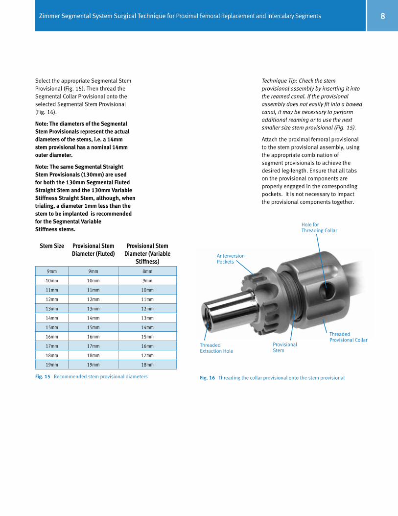
Select the appropriate Segmental Stem Provisional (Fig. 15). Then thread the Segmental Collar Provisional onto the selected Segmental Stem Provisional (Fig. 16).
Note: The diameters of the Segmental Stem Provisionals represent the actual diameters of the stems, i.e. a 14mm stem provisional has a nominal 14mm outer diameter.
Note: The same Segmental Straight Stem Provisionals (130mm) are used for both the 130mm Segmental Fluted Straight Stem and the 130mm Variable Stiffness Straight Stem, although, when trialing, a diameter 1mm less than the stem to be implanted is recommended for the Segmental Variable Stiffness stems.
Technique Tip: Check the stem provisional assembly by inserting it into the reamed canal. If the provisional assembly does not easily fit into a bowed canal, it may be necessary to perform additional reaming or to use the next smaller size stem provisional (Fig. 15).
Attach the proximal femoral provisional to the stem provisional assembly, using the appropriate combination of segment provisionals to achieve the desired leg-length. Ensure that all tabs on the provisional components are properly engaged in the corresponding pockets. It is not necessary to impact the provisional components together.
Fig. 15 Recommended stem provisional diameters
Stem Size Provisional StemDiameter (Fluted)
Provisional Stem Diameter (Variable
Stiffness)9mm 9mm 8mm
10mm 10mm 9mm
11mm 11mm 10mm
12mm 12mm 11mm
13mm 13mm 12mm
14mm 14mm 13mm
15mm 15mm 14mm
16mm 16mm 15mm
17mm 17mm 16mm
18mm 18mm 17mm
19mm 19mm 18mm
Fig. 16 Threading the collar provisional onto the stem provisional
Anterversion Pockets
Hole for Threading Collar
Threaded Provisional Collar
Provisional Stem
Threaded Extraction Hole

Zimmer Segmental System Surgical Technique for Proximal Femoral Replacement and Intercalary Segments9
Insert the femoral provisional assembly into the femoral canal and evaluate the fit. Check the fit of the stem collar on the bone surface to determine if the stem is fully seated. Assess the version of the proximal femoral provisional and determine whether a rotation adjustment will be necessary.
If a bowed stem is being used, mark the lateral femoral bone in line with the mark on the Segmental Bowed Stem Provisional to provide a reference point for proper orientation of the implant (Fig. 17).
Insert the appropriate femoral head and acetabular provisional components and perform a trial reduction. If leg length, alignment, range of motion, and stability are acceptable, proceed with the next step. If the joint is tight at full extension or during push-pull, try a shorter offset head provisional or recheck the cuts and remove bone from the femur as necessary. If the joint is loose at full extension or during push-pull, try the longer offset head provisional or recheck the cuts and try the next length segment provisional. Check stability while externally and internally rotating the limb.
Note: The femoral neck offset for either the MOST Options Basic Proximal Femoral or the Segmental Proximal Femoral Component is approximately 38mm while the offset for the MOST Options Proximal Femur with tissue attachments is 44mm. The component height for both is 80mm to head center (for +0mm) (Fig. 18).
Note: Consider decreasing the amount of anteversion to reduce risk of anterior dislocation. Also, consider reconstructing the capsule in a purse string fashion to reduce risk of posterior dislocation.
See the Zimmer Compatibility Website (www.productcompatibility.zimmer.com) for details on which components are compatible with both the Zimmer Segmental System and MOST Options proximal femoral components.
Fig. 17 Alignment Slot
Fig. 18 Zimmer Segmental System and MOST Options Proximal Femoral Components
Anterversion Pockets
Alignment Slot
MOST Options Proximal Femur with Tissue Attachments
45°
44mm
Zimmer Segmental System Proximal Femur
80mm 80mm
45°
38mm

Zimmer Segmental System Surgical Technique for Proximal Femoral Replacement and Intercalary Segments 10
Use caution not to over-lengthen the reconstruction in order to achieve longitudinal stability as over-lengthening may place undue stress on vital nerve or vascular structures.
If a version adjustment is necessary, use the Segmental Taper Separator to disassemble the provisional taper (Fig. 19). The anteversion pockets and tabs on the provisional components allow the component rotation to be adjusted in a controllable manner in 20° increments.
Note: When a bowed Segmental Stem (fluted or variable stiffness) is used with a MOST Options Proximal Femoral, the attachment of a Male-Female Segment is required because the bowed stem has only small slots. This allows the hip version to be adjustable in 20° increments without rotating the stem in the canal. When using a straight Stem, version can also be adjusted similarly with a Male-Female Segment being added to the construct.
Step 2: Disassemble the Provisional Components
Use the Segmental Taper Separator to disengage the Proximal Femoral Provisional and the Male-Female Segment Provisional, if used. Before employing the Segmental Taper Separator, make sure that the inside wedging portion of the instrument is fully retracted and centered within its housing. To orient the instrument correctly, insert the tabs of the separator into the anteversion pockets with the flat of the separator toward the joint as etched on the instrument (Fig. 20). Slowly turn the handle clockwise until the tapers are disengaged, taking care not to pinch fingers against the rotating impactor cap. If necessary, lightly tap the impactor cap on the instrument to facilitate taper disassembly.
Fig. 21 Slaphammer groove diagram
Provisional Slaphammer Adapter (two grooves)
Implant Slaphammer Adapter (one groove)
Fig. 19 Disassemble the Provisional Taper Fig. 20 Proper Segmental Taper Separator orientation
Note: To protect the taper integrity of the femoral provisional components, use only the Segmental Taper Separator with the turning handle when disassembling the femoral provisional construct.
Thread the Provisional Slaphammer Adaptor (Fig. 21) onto the slaphammer and thread it into the stem provisional. Impact the slaphammer to remove the stem provisional.

Zimmer Segmental System Surgical Technique for Proximal Femoral Replacement and Intercalary Segments11
Implant Assembly and Insertion
Step 1: Assemble and Implant the Final Implants
There are two options for assembling and inserting the final implants. The final construct can be completely assembled on the back table and inserted as a single unit (recommended when using Fluted stems). Alternatively, if preferred, the stem and collar can be assembled and inserted first, and then the segment and proximal femoral component can be assembled and impacted onto the implanted stem.
Attaching the Stem CollarAll Segmental Stems must be used with collars, and all collars must be cemented to the stems. Be sure to verify compatibility of the collar with the stem size being used on the product label before the implant packages are opened.
Technique Tip: If cementing a Segmental Fluted Stem or Zimmer acetabular component, consider using two batches of bone cement. The first can be used to cement the collar to the stem, and the second for the stem and/or acetabular component.
Note: If implanting the complete construct as a single unit, all components of the construct must be assembled and impacted together before cementing the collar to the stem. This prevents the assembly impaction force from being directly placed onto the cemented stem collar.
Note: Avoid notching, scratching, or directly striking implants during assembly.
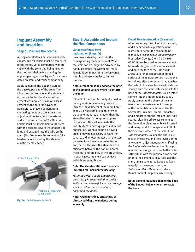
Apply cement in the doughy state to the base/taper end of the stem. Then slide the stem collar over the stem and advance it to the shank area where cement was applied. Clean off excess cement as the collar is advanced. Care should be taken to prevent cement from contacting the taper, the anteversion adjustment pockets, and the external surfaces of Trabecular Metal Material specifically where the collar will contact the cortical bone. Collars must be assembled to the stem with the pockets toward the hip joint and engaged into the tabs on the stem (Fig. 22). Allow the cement to fully harden before inserting the construct into the canal. The overall assembled Variable Stiffness stem/collar construct is shown in Fig. 23.
Fig. 22 Collar Assembly Detail
Fig. 23 Assembled (cemented) Variable Stiffness Stem and Collar construct
Collar Alignment Tab
Pocket on Trabecular Metal Collar

Zimmer Segmental System Surgical Technique for Proximal Femoral Replacement and Intercalary Segments 12
Implanting the Construct as a Single UnitIf using a Male-Female Segment, assemble it to the selected Proximal Femoral Component using the Segmental Proximal Femur Impactor (Fig. 24). Impact the assembly together with the Segmental Implant/Provisional Female Taper Impactor assembled to the Universal Impactor Handle. Use a mallet to firmly tap the tapers to the seated position.
Note: Remove any debris from the tapers prior to assembly of the tapered components.
When using a Variable Stiffness or Fluted Stem with back-table assembly, the stem must be impacted onto the hip component or segment before inserting the collar onto the stem. With the hip component resting on the Segmental Proximal Femur Impactor on the back table, place the stem onto the hip component or segment, ensuring that the anteversion tabs are properly aligned. If using a bowed stem, the stem tip should extend anatomically posteriorly with respect to the proximal femur.
When impacting the Variable Stiffness Stem into the hip component or segment, the Variable Stiffness Stem Impaction Sleeve must be used to avoid damaging the prongs on the Variable Stiffness Stem tip. Slide the Variable Stiffness Stem Impaction Sleeve over the stem until the notches on the sleeve capture the collar alignment tabs on the stem base (Fig. 25). Use a two-pound mallet to solidly strike the impaction head of the sleeve. This will impact the stem into the hip component or segment.
Fig. 25 Variable Stiffness Stem Impaction Sleeve slid over the Variable Stiffness Stem implant for taper impaction into the implant construct.
Note: Impacting the taper more than once may loosen the taper connection.
Note: Do not strike the tip of the Variable Stiffness Stem with any instrument, as this may damage the prongs created by the slots.
Fig. 24 Segmental Proximal Femur Impactor
Note: The segmental anteversion tabs must be positioned in either the direct A/P or M/L direction. This will facilitate access for the Segmental Taper Separa-tor, should disassembly be required in the future (Fig. 26).
Fig. 26 Anteversion Tab Positioning
A/P
M/L
Avoid
Zimmer Segmental System Surgical Technique for Proximal Femoral Replacement and Intercalary Segments13
Implanting the Fluted Stem/Collar/ Segment/Proximal Femur as Single UnitAfter cementing the collar onto the stem, and if desired, use a plastic cement restrictor to permit the cement to be manually pressurized. A Bigliani/Flatow® Pressurizer Sponge (item # 00-4301-035-01) may be used to prevent cement from extruding out of the femoral canal and onto the face of the Trabecular Metal Collar that contacts that planed surface of the femoral cortex. If using this technique, after the cement that attaches the collar to the stem has cured, slide the sponge onto the stem until it contacts the base of the Trabecular Metal Collar. Inject cement into the intramedullary canal. Apply cement to the shank of the stem to ensure adequate cement coverage at the implant/bone interface. Use the Segmental Proximal Femoral Impactor and a mallet to tap the implant until fully seated, cleaning off excess cement as the femoral implant assembly is inserted and being careful to keep cement off of the external surfaces of the smooth or Trabecular Metal Collars, the entire sur-face of the tapers, and the crevices of the anteversion adjustment pockets. If using the Bigliani/Flatow Pressurizer Sponge, remove the sponge just prior to the collar sitting flush with the prepared cortex and prior to the cement curing. Fully seat the stem, taking care not to leave any foam material in the wound or on the Trabecular Metal Material’s surface. Do not implant the pressurizer sponge.
Note: Cement must be added to the base of the Smooth Collar where it contacts the bone.
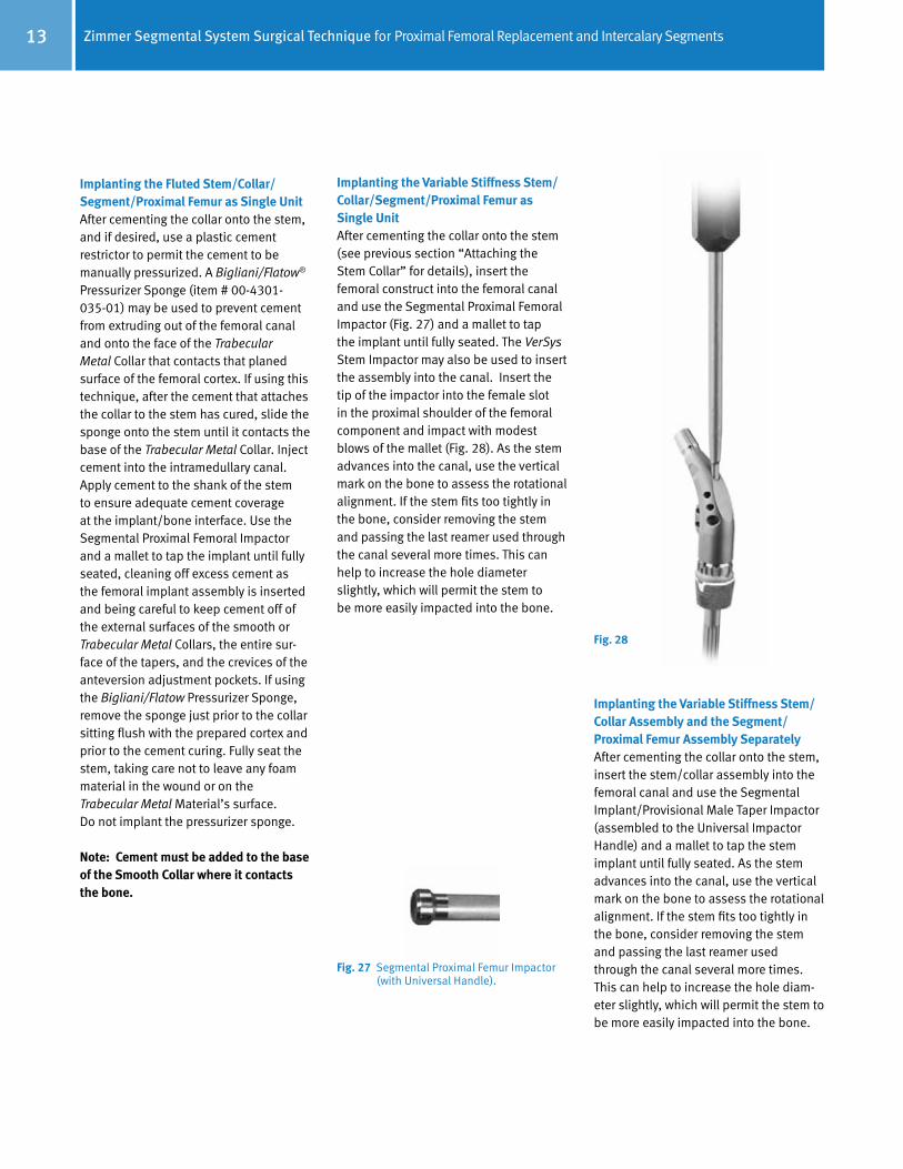
Fig. 27 Segmental Proximal Femur Impactor (with Universal Handle).
Implanting the Variable Stiffness Stem/Collar Assembly and the Segment/ Proximal Femur Assembly SeparatelyAfter cementing the collar onto the stem, insert the stem/collar assembly into the femoral canal and use the Segmental Implant/Provisional Male Taper Impactor (assembled to the Universal Impactor Handle) and a mallet to tap the stem implant until fully seated. As the stem advances into the canal, use the vertical mark on the bone to assess the rotational alignment. If the stem fits too tightly in the bone, consider removing the stem and passing the last reamer used through the canal several more times. This can help to increase the hole diam-eter slightly, which will permit the stem to be more easily impacted into the bone.
Implanting the Variable Stiffness Stem/Collar/Segment/Proximal Femur as Single UnitAfter cementing the collar onto the stem (see previous section “Attaching the Stem Collar” for details), insert the femoral construct into the femoral canal and use the Segmental Proximal Femoral Impactor (Fig. 27) and a mallet to tap the implant until fully seated. The VerSys Stem Impactor may also be used to insert the assembly into the canal. Insert the tip of the impactor into the female slot in the proximal shoulder of the femoral component and impact with modest blows of the mallet (Fig. 28). As the stem advances into the canal, use the vertical mark on the bone to assess the rotational alignment. If the stem fits too tightly in the bone, consider removing the stem and passing the last reamer used through the canal several more times. This can help to increase the hole diameter slightly, which will permit the stem tobe more easily impacted into the bone.
Fig. 28

Zimmer Segmental System Surgical Technique for Proximal Femoral Replacement and Intercalary Segments 14
DisassemblyIf disassembly is necessary during surgery, the Segmental Taper Separator is designed to enable separation of the junctions between segments, stems and femoral implants without damaging the tapers.
Step2: Reattach the Greater Trochanter and Soft Tissues
To reattach tissue to the Segmental Proximal Femoral Component, use the suture of choice, passing the suture through the holes on the component and securing them in the desired position.
To reattach the greater trochanter and soft tissues to the MOST Options Proximal Femur with tissue reattachment, see pages 45-46 of the Zimmer MOST Options System Surgical Technique (97-5010-002-00).
Step 3: Femoral Head Assembly
Once the final implant assembly is fully seated, place the desired femoral head provisional onto the taper of the implant. Assess offset, leg length, joint stability and range of motion.
When the appropriate femoral head has been confirmed, remove the femoral head provisional. Thoroughly clean and dry the taper of the proximal femoral component. Then place the selected femoral head on the taper and twist slightly to secure it. Impact it by striking the head impactor with one sharp blow of the mallet. Test the security of the head fixation by trying to remove it by hand.
Reduce the hip and assess offset, leg length, joint stability and range of motion.
Step 4: Closure
Before closing, thoroughly cleanse the surgical site of bone chips, bone cement, and any other debris. Foreign particles at the articulating interface may cause excessive wear.
Fig. 30 Fig. 29
The Segmental Proximal Femoral Replacement Assembly may also be removed with the VerSys Extractor Hook (Item # 00-6601-002-00) threaded onto the VerSys Slaphammer (Item # 00-6651-006-00). Insert the hook through the most distal hole on the lateral shoulder of the Proximal Femoral Component (Fig. 31) and use the slaphammer to provide the force necessary to remove the component, taking care not to damage the surrounding bone while the implant is being removed.
Fig. 31
If using a segment, assemble it to the Proximal Femur using the Segmental Proximal Femur Impactor. Impact the assembly together with the Segmental Implant/Provisional Female Taper Impactor assembled to the Universal Impactor Handle. Use a mallet to firmly tap the tapers to the seated position.
Place the proximal femoral assembly onto the stem taper, and use the Segmental Proximal Femoral Impactor (with Universal Handle) and a mallet to secure the two assemblies together.
The VerSys Stem Impactor may also be used to insert the assembly into the canal. Insert the tip of the impactor into the female slot in the proximal shoulder of the femoral component and impact with modest blows of the mallet (Fig. 28 previous page).
Note: When using the smooth collar on the Variable Stiffness Stem, at the time of implantation, cement must be added to the base of the smooth collar where it contacts the bone.
Before employing the Segmental Taper Separator, make sure that the inside wedging portion of the instrument is fully retracted and centered within its housing. To orient the instrument correctly, insert the tabs of the separator into the anteversion pockets with the flat of the separator toward the proximal femur as etched on the instrument (Fig. 29). Slowly turn the handle clockwise until the tapers disengage, taking care not to pinch fingers against the rotating impactor cap. If necessary, lightly tap the impactor cap on the instrument to facilitate taper disassembly. If additional force is needed to disengage the taper, two Segmental Taper Separators may be used on opposite sides of each other (Fig. 30).

Zimmer Segmental System Surgical Technique for Proximal Femoral Replacement and Intercalary Segments15
Mid-shaft Femur Replacement with the Segmental Intercalary Segments
The Zimmer Segmental System Intercalary Segments provide a means for reconstructing a midshaft defect or tumor in the femur.
The design of the Intercalary Segments incorporates a short shaft with a female taper on each end. They are manufactured from Tivanium® (Ti-6Al-4V) Alloy, and are available in three lengths: 45mm, 55mm, and 65mm. They can also be used in conjunction with Segmental Male- Female Segments to help restore leg length while accommodating larger defects, and as Female-Female segments in other Segmental applications. Both ends contain tabs that mate with the corresponding alignment grooves in compatible Segmental Stems or Segments.
The Zimmer Segmental System Intercalary Segments can be used with both Segmental Fluted and Variable Stiffness stems. Fluted stems must be cemented in the IM canal. Variable Stiffness Stems must be used uncemented in the IM canal.
Note: Because preoperative planning cannot always predict the extent of a defect or tumor, the surgery may be changed to a distal, proximal, or total femur replacement if the condition of the bone dictates a resection that is too far proximal and/or distal to accept the length of the stem extensions (minimum intramedullary length on either side of the intercalary implant and stem collar is 130mm).
Note: Do not use a Segmental Intercalary Segment with MOST Options Stems. These components are not compatible.
Femoral Resection and Preparation Step 1: Excise the Defective Femoral Bone
After exposing the femoral shaft at the defect, move the leg into a reproducible position. Then check leg length and alignment. Based on preoperative radiographic assessment, determine the implant configuration and select the proper components.
To establish the resection levels, measure the anticipated resection length across the bone defect/tumor that is appropriate for the implant configuration (Fig. 32). Use a marker, osteotome, or electrocautery to make horizontal lines marking the proposed resection space. To help assess the rotational alignment of the components, make vertical reference marks on the bone above and below the resection space.
Note: Each large taper connection adds approximately 2mm to the total length.
Fig. 32 Femoral Resection Lengths
Femoral Resection LengthsIntercalary Segments Stem/Collar
(Two Stems Required)Male-Female Segments Resection Length*
45mm 30+30mm
0 109mm
30mm 141mm
35mm 146mm
55mm 30+30mm
0 119mm
30mm 151mm
35mm 156mm
65mm 30+30mm
0 129mm
30mm 161mm
35mm 166mm
40mm 171mm
45mm 176mm
* Denotes the length of the implants (includes the 2mm added by each taper junction)
Resection Length

Zimmer Segmental System Surgical Technique for Proximal Femoral Replacement and Intercalary Segments 16
Note: The minimum resection is 109mm.
Technique Tip: Resecting slightly more than the length of the assembled implants will make assembling the intercalary component easier and reduce the amount of distraction necessary; however, it will also cause the limb to be shortened and could reduce tissue tension.
Technique Tip: It may also be helpful to mark horizontal lines at a predetermined distance above and below the resection levels that can be used to assess leg length during trial reduction.
Step 2: Ream the Femoral Canal
Note: The diameters indicated for the Segmental Variable Stiffness Stems represent the actual diameters of the stems, which include the height of the splines. Therefore, the diameter of the reamed hole should be 0.5mm less than the labeled stem size to provide for additional apposition of the distal splines within the femoral canal. For a Segmental Fluted Stem, the diameter of the reamed hole should be 2mm greater than the labeled stem size to provide for an adequate cement mantle.
Note: When using Variable Stiffness Stems in an uncemented application, cement must still be used to attach the Trabecular Metal or Smooth Collar to the stem.
For a straight Variable Stiffness stem, use the straight reamers from the VerSys Hip System. For a bowed stem, flexible reamers from the Pressure Sentinel Intramedullary Reaming System are recommended: use the Pressure Sentinel Reamer Expanded Hip Set (00-2228-000-03) or the ZMR Flexible Reamer Set (00-9975-000-11). If preferred, the flexible reamers can also be used for a straight stem to allow for point contact of the stem in the canal.
Reaming for a Press-Fit Variable Stiffness Stem Progressively ream the femoral canal until the reamer contacts cortical bone. Ream to a depth slightly greater than the length of the selected stem to allow proper seating of the stem shoulder on cortical bone. To achieve the press fit, under-ream the bone by 0.5mm and check the fit of the stem in the canal. If the stem fits too tightly in the bone, consider removing the stem and passing the last reamer used through the canal several more times. This can help to increase the hole diameter slightly, which will permit the stem to be more easily impacted into the bone.
For a straight stem using a straight reamer, do not increase the hole diameter to be equal to or greater than the diameter of the stem – this will eliminate the possibility of achieving a press fit (Fig. 33). For this reason, only VerSys straight reamers should be used (since they have 0.5mm increments), if using straight reamers. NexGen straight reamers should not be used, since they have 1mm increments. However, for a bowed stem or a straight stem in a flex-reamed bowed canal, it may be necessary to ream the medullary canal to a diameter larger than the stem to be implanted depending on how well the implant geometry matches the bow of the patient’s femur. In such cases, the stem can achieve solid three-point fixation. If progressive reaming does not yield an appropriate press fit, consider using a different size implant or switching to a cemented application using a Segmental Fluted Stem.
Fig. 33 Recommended reamer diameters
Reaming for a Cemented Fluted Stem Progressively ream the femoral canal until the reamer contacts cortical bone. Ream to a depth slightly greater than the length of the selected stem to allow proper seating of the stem shoulder on cortical bone and placement of a cement restrictor if desired. To allow for a cement mantle in the canal, select a stem 1-2mm smaller than the largest reamer size used to ream the canal. NexGen (or VerSys) straight reamers can be used for Segmental Fluted Stems, if desired.
Stem Size
Minimum Ream Diameter
(Fluted)
Minimum Ream Diameter
(Variable Stiffness)
9mm 11mm 8.5mm
10mm 12mm 9.5mm
11mm 13mm 10.5mm
12mm 14mm 11.5mm
13mm 15mm 12.5mm
14mm 16mm 13.5mm
15mm 17mm 14.5mm
16mm 18mm 15.5mm
17mm 19mm 16.5mm
18mm 20mm 17.5mm
19mm 21mm 18.5mm

Zimmer Segmental System Surgical Technique for Proximal Femoral Replacement and Intercalary Segments17
Step 3: Plane the Femoral Bone
Thread the appropriately sized Segmental Planer Pilot (130mm long) for the stem diameter selected onto the MOST Options Femoral/Tibial Planer (Fig. 34). If the anatomy requires the use of a shorter planer pilot, use the 75mm length Planer Pilots. A Planer Pilot 1-2mm smaller than the stem diameter chosen can be used to facilitate insertion into a curved medullary canal (Fig. 35). Attach the assembly to a power driver with a Zimmer adapter. Then plane the resected distal femur until the cortical bone is smooth and flat.
To aid in removing the Planer Pilot from the Planer, insert the pin on the Segmental Collar Provisional Sizer through the cross-hole and, while securing the noncutting end of the planer, turn the shank counterclockwise.
Fig. 35 Recommended Planer Pilot diameters
Step 4: Counterbore the Femoral Canal (for Variable Stiffness Stem applications only)
The full diameter of a Variable Stiffness Stem proximal to the splines will be 0.5mm greater than the reamed diameter of the femoral canal. Counterboring this proximal portion is required for proper insertion of the stem in the intramedullary canal.
Thread the appropriate size Counterbore Reamer Tip into the Counterbore Stop Plate (Fig. 36a). Then insert the assembly into a power driver. Insert the pin on the Segmental Collar Provisional Sizer through the cross-hole of the Counterbore Reamer Tip and turn the shank to tightly secure it to the Counterbore Stop Plate (Fig. 36b).
Insert the assembly into the reamed canal and counterbore the proximal canal (Fig. 37). The Counterbore Stop Plate will serve as a stop when the appropriate depth is achieved.
Do not over ream or elongate the hole.
Fig. 36a Counterbore Reamer Tip and Counterbore Reamer Stop Plate
Fig. 36b Counterbore Reamer Tip and Counterbore Reamer Stop Plate Assembly
Fig. 37 Counterbore the Intramedullary Canal
Counterbore Reamer Stop Plate
Counterbore Reamer Tip
Counterbore Reamer Tip
Segmental Collar Provisional Sizer
Stem Size Planer Pilot
Diameter (Fluted)
Planer Pilot Diameter
(Variable Stiffness)9mm 9mm 8mm
10mm 10mm 9mm11mm 11mm 10mm12mm 12mm 11mm13mm 13mm 12mm14mm 14mm 13mm15mm 15mm 14mm16mm 16mm 15mm17mm 17mm 16mm18mm 18mm 17mm19mm 19mm 18mm
Fig. 34 Threading the Planer Pilot onto the Planer
Planer
Planer Pilot

Zimmer Segmental System Surgical Technique for Proximal Femoral Replacement and Intercalary Segments 18
Stem Diameter Smooth Collar (Item #) Trabecular Metal Collar (Item #) Stem I/M Length (Stem Type)
9-16mm 30mm for 9-16mm stems (00-5852-042-09)
• 25mm for 9-16mm stems (00-5852-040-25)• 30mm for 9-16mm stems (00-5852-040-30)• 35mm for 9-16mm stems (00-5852-040-35)
• 130mm Straight (Fluted and Variable Stiffness)• 190mm Straight (Fluted)• 190mm Bowed (Variable Stiffness)• 250mm Bowed (Fluted)*
17-19mm 30mm for 17-19mm stems (00-5852-042-17)
• 30mm for 17-19mm stems (00-5852-041-30)• 35mm for 17-19mm stems (00-5852-041-35)
• 130mm Straight (Fluted and Variable Stiffness)• 190mm Straight (Fluted)• 190mm Bowed (Variable Stiffness)• 250mm Bowed (Fluted)*
Trial Reduction
Step 1: Assemble Provisional Components and Perform Trial Reduction
Stem Extension Provisional Assembly/InsertionUse the Segmental Collar Provisional Sizer to select the collar size that provides the best coverage of the bone surface. If using a smooth collar, only the 30mm outer diameter collar is available. As an option, the collar sizer may be attached to the selected Planer Pilot to facilitate collar selection. Confirm that the stem and stem collar sizes are compatible (see figures 38 and 39).
Fig. 38 Stem/Collar Compatibility
Note: The bowed stem (not shown) have the same compatibility with the collars.
Fig. 39 Variable Stiffness Stem Compatibility Table
Trabecular Metal Collars
Smooth Collars
25mm 30mm35mm
30mm
17mm
18mm
19mm
Trabecular Metal Collars
30mm35mm
30mm
Smooth Collars
* 250mm Bowed Stem is only available in 12-19mm
9mm
10mm
11mm
12mm
13mm
14mm
15mm
16mm

Zimmer Segmental System Surgical Technique for Proximal Femoral Replacement and Intercalary Segments19
For the Variable Stiffness Stem, select the appropriate Segmental Stem Provisional that is 1mm smaller than the anticipated Variable Stiffness stem component size, e.g., if a 15mm stem will be implanted, use a 14mm stem provisional. Then thread the Segmental Collar Provisional onto the selected Segmental Variable Stiffness Stem Provisional (Fig. 40).
Insert the stem provisional assemblies into the reamed canals and evaluate the fit. If a stem provisional does not easily fit into a bowed canal, it may be necessary to perform additional reaming or to use the next smaller size stem provisional. Check the fit of the stem collar on the bone surface to determine if the stem is fully seated.
If a bowed stem is being used, mark the femoral bone in line with the mark on the Segmental Bowed Variable Stiffness Stem Provisional to provide a locator for proper orientation of the implant (Fig. 41).
Fig. 40 Threading the collar provisional onto the stem provisional
Anterversion Pockets
Hole for Threading Collar
Threaded Provisional Collar
Provisional Stem
Threaded Extraction Hole
Fig. 41 Alignment Slot
Anterversion Pockets
Alignment Slot

Zimmer Segmental System Surgical Technique for Proximal Femoral Replacement and Intercalary Segments 20
Intercalary Segment Provisional Assembly/InsertionAfter inserting the provisional stems, select the appropriate sized Intercalary Segment Provisional and Male-Female Segment Provisional, if used.
Note: To facilitate disassembly, the Segmental Intercalary Segment Provisionals are not designed for a taper fit with the mating provisionals.
If using a Male-Female Segment, place the appropriate Male-Female Segment Provisional onto the base of one of the two stem provisionals and use the Segmental Implant/Provisional Male Taper Impactor with the Universal Handle to impact the taper.
Connect the two halves of the Provisional Intercalary Segment Assembly together. One of the two intercalary provisional halves is designed with a slight boss to fit inside the other half (Fig. 42). Place the provisional into the jaws of the Segment Inserter/Remover and tighten the thumbscrew on the instrument (Fig. 43). The Segment Inserter/Remover will facilitate the assembly by providing leverage to manipulate the femur. Place one end of the intercalary provisional onto the base of one of the stem provisionals, or the Male-Female Segment Provisional. Then place the other end on the base of the other stem provisional, being careful to avoid distracting the leg more than necessary.
Fig. 42 Provisional Intercalary Segments
Fig. 43 Segment Inserter/Remover holding the Provisional Intercalary Segments together
This intercalary trialing technique provides a similar amount of distraction as the intercalary implantation would require.
Ensure that all tabs on the provisional components are properly engaged in the corresponding pockets when applicable. It is not necessary to impact the provisional components together.

Zimmer Segmental System Surgical Technique for Proximal Femoral Replacement and Intercalary Segments21
Step 2: Disassemble the Provisional Components (if a Male-Female Segment Provisional was used)
Provisional DisassemblyRemove the provisionals by first removing the Segment Inserter/Remover. Distract the leg and disengage the two halves of the Provisional Intercalary Segment assembly or disengage the bosses of the Provisional Intercalary Segment Spacer. Then use the Segmental Taper Separator with the turning handle to disconnect any Male-Female Segment Provisionals, if used. This instrument will protect the taper integrity of the provisional components.
Before employing the Segmental Taper Separator, make sure that the inside wedging portion of the instrument is fully retracted and centered within its housing. To orient the instrument correctly, insert the tabs of the separator into the anteversion pockets with the flat of the separator toward the female side of the taper connection to be separated. Slowly turn the handle clockwise until the tapers are disengaged, taking care not to pinch fingers against the rotating impactor cap. If necessary, lightly tap the impactor cap on the instrument to facilitate taper disassembly.
If the stem components cannot be removed by hand, thread the Provisional Slaphammer Adapter onto the slaphammer and thread it into the stem provisional. Impact the slaphammer to remove the stem provisional.
A second intercalary provisional option is available if minimal distraction while trialing is desired without using a Male-Female Segment Provisional in the intercalary trial construct (Fig. 44). In this case, after inserting the Segmental Provisional Stems, slide the boss on the appropriately sized (45, 55 or 65mm) Provisional Intercalary Segment Spacer into one of the threaded holes on the end of the provisional stem. Then slide the other Provisional Intercalary Segment Spacer boss into the other Segmental Provisional Stem threaded hole (Fig. 45). The Segment Inserter/Remover can also be used to facilitate the assembly of this type of provisional construct. The amount of distraction required to assemble this provisional construct will be less than the amount of distraction required to assemble the implant, so the amount of soft-tissue tension should be noted for the final implantation.
Fig. 44 Provisional Intercalary Segment Spacer
Note: this method for trialing will not work if a Male-Female Segment Provisional is in the construct, because it does not have a threaded hole at the end of the male taper.
Evaluate the fit of the provisionals and make adjustments as necessary. Check the leg length, alignment, and stability. Use caution not to over-lengthen the reconstruction in order to achieve longitudinal stability. If the soft tissues are too tight and the construct cannot be shortened, a soft tissue release or additional bone resection may be necessary. If additional bone is resected, it will also be necessary to perform additional reaming to ensure that the reaming depth is adequate.
Fig. 45 Provisional Intercalary Segment Spacer and Stem Provisional assembly
Zimmer Segmental System Surgical Technique for Proximal Femoral Replacement and Intercalary Segments 22
Implant Assembly and Insertion Step 1: Prepare the Stems
All Segmental Stems must be used with collars, and all collars must be cemented to the stems. Verify compatibility of the collar with the stem size being used on the product label before opening the implant packages. See Figure 38 for more detail on stem and collar compatibility.
Apply cement in the doughy state to the base/taper end of the stem. Then slide the stem collar over the stem and advance it to the shank area where cement was applied. Clean off excess cement as the collar is advanced. Be careful to prevent cement from contacting the taper, the anteversion adjustment pockets, and the external surfaces of Trabecular Metal Material. Collars must be assembled to the stem with the pockets toward the anatomical joint and engaged into the tabs on the stem (Fig. 46). Allow the cement to fully harden before inserting the stem into a mating female taper.
Fig. 46 Collar Assembly Detail
Step 2: Assemble and Implant the Final Components
Variable Stiffness Stem Implantation (Press-fit)Insert each stem by hand into the corresponding medullary canal. When the stem can no longer be advanced by hand, assemble the Segmental Male-Female Taper Impactor to the Universal Handle and use a mallet to impact the stem.
Note: Cement must be added to the base of the Smooth Collars where it contacts the bone.
If the fit of the stem is too tight, consider making additional reaming passes to increase the diameter of the medullary canal. Do not ream a straight stem to a diameter equal to or greater than the stem diameter if attempting to press fit the stem. This will eliminate the possibility of achieving a press fit in this application. When inserting a bowed stem it may be necessary to ream the canal to a diameter greater than the stem diameter to achieve adequate fixation and/or to fully insert the stem due to a mismatch between the natural bow of the femur and the bow of the prosthesis. In such cases, the stem can achieve solid three-point fixation.
Note: The Variable Stiffness Stems are indicated for uncemented use only.
Technique Tip: In some applications, particularly in cases with thin cortical walls, it can be beneficial to use cerclage wires to reduce the possibility of damaging the bone.
Note: Avoid notching, scratching, or directly striking the implants during assembly.
Collar Alignment Tab
Pocket on Trabecular Metal Collar
Fluted Stem Implantation (Cemented)After cementing the collar onto the stem, and if desired, use a plastic cement restrictor to permit the cement to be manually pressurized. A Bigliani/Flatow Pressurizer Sponge (item # 00-4301-035-01) may be used to prevent cement from extruding out of the femoral canal and onto the face of the Trabecular Metal Collar that contacts that planed surface of the femoral cortex. If using this technique, after the cement that attaches the collar to the stem has cured, slide the sponge onto the stem until it contacts the base of the Trabecular Metal Collar. Inject cement into the intramedullary canal. Apply cement to the shank of the stem to ensure adequate cement coverage at the implant/bone interface. Use the Segmental Proximal Femoral Impactor and a mallet to tap the implant until fully seated, cleaning off excess cement as the femoral implant assembly is inserted and being careful to keep cement off of the external surfaces of the smooth or Trabecular Metal Collars, the entire sur-face of the tapers, and the crevices of the anteversion adjustment pockets. If using the Bigliani/Flatow Pressurizer Sponge, remove the sponge just prior to the collar sitting flush with the prepared cortex and prior to the cement curing. Fully seat the stem, taking care not to leave any foam material in the wound or on the Trabecular Metal Material’s surface. Do not implant the pressurizer sponge.
Note: Cement must be added to the base of the Smooth Collar where it contacts the bone.
Zimmer Segmental System Surgical Technique for Proximal Femoral Replacement and Intercalary Segments23
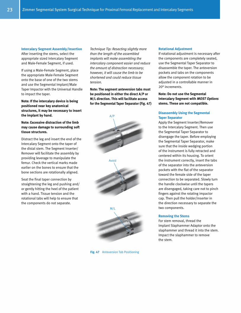
Intercalary Segment Assembly/InsertionAfter inserting the stems, select the appropriate sized Intercalary Segment and Male-Female Segment, if used.
If using a Male-Female Segment, place the appropriate Male-Female Segment onto the base of one of the two stems and use the Segmental Implant/Male Taper Impactor with the Universal Handle to impact the taper.
Note: If the intercalary device is being positioned near key anatomical structures, it may be necessary to insert the implant by hand.
Note: Excessive distraction of the limb may cause damage to surrounding soft tissue structures.
Distract the leg and insert the end of the Intercalary Segment onto the taper of the distal stem. The Segment Inserter/Remover will facilitate the assembly by providing leverage to manipulate the femur. Check the vertical marks made earlier on the bones to ensure that the bone sections are rotationally aligned.
Seat the final taper connection by straightening the leg and pushing and/or gently hitting the heel of the patient with a hand. Tissue tension and the rotational tabs will help to ensure that the components do not separate.
Fig. 47 Anteversion Tab Positioning
Technique Tip: Resecting slightly more than the length of the assembled implants will make assembling the intercalary component easier and reduce the amount of distraction necessary; however, it will cause the limb to be shortened and could reduce tissue tension.
Note: The segment anteversion tabs must be positioned in either the direct A/P or M/L direction. This will facilitate access for the Segmental Taper Separator (Fig. 47)
Rotational AdjustmentIf rotational adjustment is necessary after the components are completely seated, use the Segmental Taper Separator to disassemble the taper. The anteversion pockets and tabs on the components allow the component rotation to be adjusted in a controllable manner in 20° increments.
Note: Do not use the Segmental Intercalary Segment with MOST Options stems. These are not compatible.
Disassembly Using the Segmental Taper SeparatorApply the Segment Inserter/Remover to the Intercalary Segment. Then use the Segmental Taper Separator to disengage the taper. Before employing the Segmental Taper Separator, make sure that the inside wedging portion of the instrument is fully retracted and centered within its housing. To orient the instrument correctly, insert the tabs of the separator into the anteversion pockets with the flat of the separator toward the female side of the taper connection to be separated. Slowly turn the handle clockwise until the tapers are disengaged, taking care not to pinch fingers against the rotating impactor cap. Then pull the holder/inserter in the direction necessary to separate the two components.
Removing the StemsFor stem removal, thread the Implant Slaphammer Adaptor onto the slaphammer and thread it into the stem. Impact the slaphammer to remove the stem.
A/P
M/L
Avoid


Contact your Zimmer representative or visit us at www.zimmer.com
97-5850-007-00 1010-K13 2.5ML Printed in USA ©2010 Zimmer, Inc.
Barcode Needed+H124975850007001/$101029K105
This documentation is intended exclusively for physicians and is not intended for laypersons.Information on the products and procedures contained in this document is of a general nature and does not represent and does not constitute medical advice or recommendations. Because this information does not purport to constitute any diagnostic or therapeutic statement with regard to any individual medical case, each patient must be examined and advised individually, and this document does not replace the need for such examination and/or advice in whole or in part. Please refer to the package inserts for important product information, including, but not limited to, contraindications, warnings, precautions, and adverse effects.
The CE mark is valid only if it is also printed on the product label.