imagery support data (isd) documentation - amazon … · 5 digitalglobe imagery support data (isd)...
TRANSCRIPT
Imagery Support Data (ISD) Documentation
v. 1.1.2

2 DigitalGlobe Imagery Support Data (ISD) Documentation v. 1.1.2 October 2014
Disclaimer & Copyright
Copyright © 2014
DigitalGlobe, Inc. All rights reserved.
Access to DigitalGlobe products and sensors is limited to existing re-seller terms and conditions.
THIS PUBLICATION IS PROVIDED "AS IS" WITHOUT WARRANTY OF ANY KIND, EITHER EXPRESS OR IMPLIED, INCLUDING, BUT NOT LIMITED TO, THE IMPLIED WARRANTIES OF MERCHANTABILITY, FITNESS FOR A PARTICULAR PURPOSE, OR NON-INFRINGEMENT.
THIS PUBLICATION COULD INCLUDE TECHNICAL INACCURACIES OR TYPOGRAPHICAL ERRORS. CHANGES ARE PERIODICALLY ADDED TO THE INFORMATION HEREIN; THESE CHANGES WILL BE INCORPORATED IN NEW EDITIONS OF THE PUBLICATION. DIGITALGLOBE MAY MAKE IMPROVEMENTS AND/OR CHANGES TO THE PRODUCT(S) AND/OR THE PROGRAM(S) DESCRIBED IN THIS PUBLICATION AT ANY TIME.
3 DigitalGlobe Imagery Support Data (ISD) Documentation v. 1.1.2 October 2014
Contents Disclaimer & Copyright ........................................................................................................................... 2 List of Figures .......................................................................................................................................... 4 List of Tables ........................................................................................................................................... 5 1 Introduction ......................................................................................................................................... 6 2 Image Support Data ............................................................................................................................. 7
2.1 ISD File Description ..................................................................................................................................... 8 2.2 File Layout ................................................................................................................................................... 8
3 General Format and Conventions ..................................................................................................... 10 3.1 General File Format ................................................................................................................................... 10 3.2 PVL Format ................................................................................................................................................ 10 3.3 XML Format ............................................................................................................................................... 10 3.4 Coordinate Conventions ........................................................................................................................... 10
3.4.1 Earth Coordinates (E) ..................................................................................................................... 10 3.4.2 Image Coordinates ......................................................................................................................... 11 3.4.3 Time ............................................................................................................................................... 12
4 Delivery Level Support Data .............................................................................................................. 13 4.1 Delivery Index (README) Contents ........................................................................................................... 13 4.2 Delivery Layout File ................................................................................................................................... 16 4.3 Delivery Geographic Location Map Files ................................................................................................... 16
5 Product Component-Level Support Data .......................................................................................... 21 5.1 Product Component Index (README) ....................................................................................................... 21
6 Image Metadata ................................................................................................................................ 23 6.1 Image Metadata Content .......................................................................................................................... 23
6.1.1 Heights Above Ellipsoid (HAE) ....................................................................................................... 40 6.1.2 Product Level to Product Type Relationships ................................................................................ 41
6.2 Product Browse File .................................................................................................................................. 41 6.3 Tile Map .................................................................................................................................................... 42 6.4 Rational Polynomial Coefficients .............................................................................................................. 46 6.5 Product Component XML File ................................................................................................................... 49 6.6 Manifest File .............................................................................................................................................. 51 6.7 Stereo File ................................................................................................................................................. 52
Appendix A: Example PVL Format ........................................................................................................ 55 Appendix B: Example XML Format ....................................................................................................... 58 Appendix C: Example Tile Map File ...................................................................................................... 61 Glossary ................................................................................................................................................ 62 Index ..................................................................................................................................................... 68

4 DigitalGlobe Imagery Support Data (ISD) Documentation v. 1.1.2 October 2014
List of Figures Figure 2.1 File Layout Diagram ................................................................................................................................................... 9 Figure 3.1 Earth Coordinate System ......................................................................................................................................... 11 Figure 3.2 Image Coordinate System ........................................................................................................................................ 11 Figure 6.1 Sample Product Browse File .................................................................................................................................... 41 Figure 6.2 Stereo Geometry Angles .......................................................................................................................................... 52

5 DigitalGlobe Imagery Support Data (ISD) Documentation v. 1.1.2 October 2014
List of Tables Table 2.1 Image Support Data (ISD) Files Delivered by Product Type ........................................................................................ 7 Table 4.1 Top-Level Delivery Index (README) Contents (ISDF.DEL.README) .......................................................................... 13 Table 4.2 STRIP Shapefile Delivery Names and Attributes ........................................................................................................ 16 Table 4.3 ORDER Shapefile Delivery Names and Attributes ..................................................................................................... 17 Table 4.4 TILE Shapefile Delivery Names and Attributes .......................................................................................................... 18 Table 4.5 PRODUCT Shapefile Delivery Names and Attributes ................................................................................................. 18 Table 4.6 PIXEL Shapefile Delivery Names and Attributes ........................................................................................................ 19 Table 4.7 MOSAIC_CLOSEDPOLYGONS Shapefile Delivery Names and Attributes ................................................................... 19 Table 5.1 Product Component Index (README) Contents ....................................................................................................... 21 Table 6.1 Image Metadata Contents ........................................................................................................................................ 23 Table 6.2 Product Level to Product Type Relationships ............................................................................................................ 41 Table 6.3 Tile Map Contents ..................................................................................................................................................... 42 Table 6.4 RPC Terms ................................................................................................................................................................. 47 Table 6.5 RPC00B Contents ....................................................................................................................................................... 47 Table 6.6 Stereo File Contents .................................................................................................................................................. 53

6 DigitalGlobe Imagery Support Data (ISD) Documentation v. 1.1.2 October 2014
1 Introduction This document describes the Image Support Data (ISD) format for DigitalGlobe Imagery products. These products are available in a variety of product types, and contain different ISD depending on the type of the product. This document describes the ISD, overall structure of files and specifies the data content and format of individual fields for the following DigitalGlobe product types: • Basic Products • Stereo Products • Standard Products • Orthorectified Products • Digital Elevation Model Products
This document also presents some technical information to explain the significance of the data.
The term “image” in this document often refers to a general two-dimensional image product, including a Digital Elevation Model (DEM) or another form of height model, as well as an image in the stricter sense. The context and the use of specific product type names should make it clear which meaning is intended.
7 DigitalGlobe Imagery Support Data (ISD) Documentation v. 1.1.2 October 2014
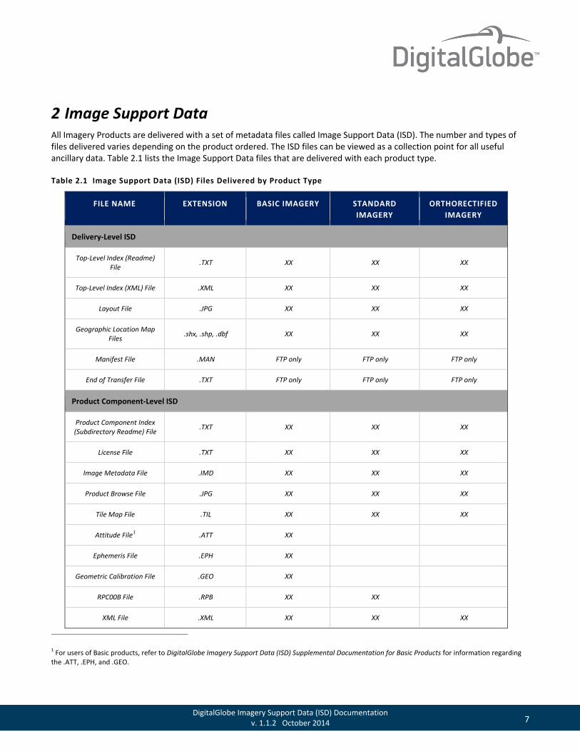
2 Image Support Data All Imagery Products are delivered with a set of metadata files called Image Support Data (ISD). The number and types of files delivered varies depending on the product ordered. The ISD files can be viewed as a collection point for all useful ancillary data. Table 2.1 lists the Image Support Data files that are delivered with each product type.
Table 2.1 Image Support Data (ISD) Files Delivered by Product Type
FILE NAME EXTENSION BASIC IMAGERY STANDARD IMAGERY
ORTHORECTIFIED IMAGERY
Delivery-Level ISD
Top-Level Index (Readme) File .TXT XX XX XX
Top-Level Index (XML) File .XML XX XX XX
Layout File .JPG XX XX XX
Geographic Location Map Files .shx, .shp, .dbf XX XX XX
Manifest File .MAN FTP only FTP only FTP only
End of Transfer File .TXT FTP only FTP only FTP only
Product Component-Level ISD
Product Component Index (Subdirectory Readme) File .TXT XX XX XX
License File .TXT XX XX XX
Image Metadata File .IMD XX XX XX
Product Browse File .JPG XX XX XX
Tile Map File .TIL XX XX XX
Attitude File1 .ATT XX
Ephemeris File .EPH XX
Geometric Calibration File .GEO XX
RPC00B File .RPB XX XX
XML File .XML XX XX XX
1 For users of Basic products, refer to DigitalGlobe Imagery Support Data (ISD) Supplemental Documentation for Basic Products for information regarding the .ATT, .EPH, and .GEO.
8 DigitalGlobe Imagery Support Data (ISD) Documentation v. 1.1.2 October 2014
FILE NAME EXTENSION BASIC IMAGERY STANDARD IMAGERY
ORTHORECTIFIED IMAGERY
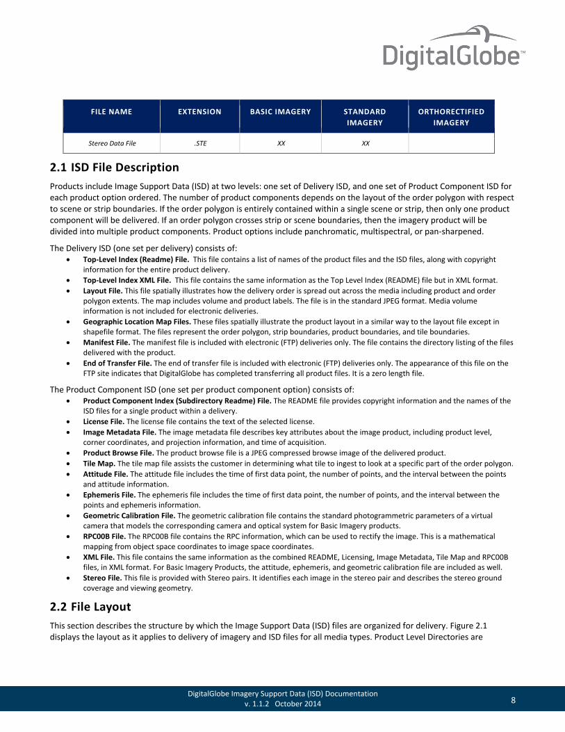
Stereo Data File .STE XX XX
2.1 ISD File Description Products include Image Support Data (ISD) at two levels: one set of Delivery ISD, and one set of Product Component ISD for each product option ordered. The number of product components depends on the layout of the order polygon with respect to scene or strip boundaries. If the order polygon is entirely contained within a single scene or strip, then only one product component will be delivered. If an order polygon crosses strip or scene boundaries, then the imagery product will be divided into multiple product components. Product options include panchromatic, multispectral, or pan-sharpened.
The Delivery ISD (one set per delivery) consists of: • Top-Level Index (Readme) File. This file contains a list of names of the product files and the ISD files, along with copyright
information for the entire product delivery. • Top-Level Index XML File. This file contains the same information as the Top Level Index (README) file but in XML format. • Layout File. This file spatially illustrates how the delivery order is spread out across the media including product and order
polygon extents. The map includes volume and product labels. The file is in the standard JPEG format. Media volume information is not included for electronic deliveries.
• Geographic Location Map Files. These files spatially illustrate the product layout in a similar way to the layout file except in shapefile format. The files represent the order polygon, strip boundaries, product boundaries, and tile boundaries.
• Manifest File. The manifest file is included with electronic (FTP) deliveries only. The file contains the directory listing of the files delivered with the product.
• End of Transfer File. The end of transfer file is included with electronic (FTP) deliveries only. The appearance of this file on the FTP site indicates that DigitalGlobe has completed transferring all product files. It is a zero length file.
The Product Component ISD (one set per product component option) consists of: • Product Component Index (Subdirectory Readme) File. The README file provides copyright information and the names of the
ISD files for a single product within a delivery. • License File. The license file contains the text of the selected license. • Image Metadata File. The image metadata file describes key attributes about the image product, including product level,
corner coordinates, and projection information, and time of acquisition. • Product Browse File. The product browse file is a JPEG compressed browse image of the delivered product. • Tile Map. The tile map file assists the customer in determining what tile to ingest to look at a specific part of the order polygon. • Attitude File. The attitude file includes the time of first data point, the number of points, and the interval between the points
and attitude information. • Ephemeris File. The ephemeris file includes the time of first data point, the number of points, and the interval between the
points and ephemeris information. • Geometric Calibration File. The geometric calibration file contains the standard photogrammetric parameters of a virtual
camera that models the corresponding camera and optical system for Basic Imagery products. • RPC00B File. The RPC00B file contains the RPC information, which can be used to rectify the image. This is a mathematical
mapping from object space coordinates to image space coordinates. • XML File. This file contains the same information as the combined README, Licensing, Image Metadata, Tile Map and RPC00B
files, in XML format. For Basic Imagery Products, the attitude, ephemeris, and geometric calibration file are included as well. • Stereo File. This file is provided with Stereo pairs. It identifies each image in the stereo pair and describes the stereo ground
coverage and viewing geometry.
2.2 File Layout This section describes the structure by which the Image Support Data (ISD) files are organized for delivery. Figure 2.1 displays the layout as it applies to delivery of imagery and ISD files for all media types. Product Level Directories are

9 DigitalGlobe Imagery Support Data (ISD) Documentation v. 1.1.2 October 2014
identified with the product ID and a three-character descriptor: PAN for Panchromatic, MUL for Multispectral, PSH for Pansharpened, and MOS for Mosaicked products.
Figure 2.1 File Layout Diagram

10 DigitalGlobe Imagery Support Data (ISD) Documentation v. 1.1.2 October 2014
3 General Format and Conventions 3.1 General File Format Image Support Data (ISD) files are provided in the Parameter Value Language (PVL). The information in PVL format is provided in multiple files while the information in XML is provided in a single file. The information provided in PVL and XML are the same semantically but differ only in syntax.
3.2 PVL Format Each tag consists of a variable length parameter name and a parameter value, in the form parameterName = value followed by a semi-colon. The value can be an integer (decimal, binary, octal, or hexadecimal), a floating-point number, a character string (one or more characters), a coordinate universal time (UTC), a set, or a list. The format for UTC time is YYYY-MM-DDThh:mm:ss.ddddddZ. Character strings values must be enclosed in double quotation marks. Sets are delimited by { }, and lists are delimited by ( ). Nested sets and lists are allowed. Comments in the file begin with a slash-asterisk (/*) and end with an asterisk-slash (*/).
Named groups begin with BEGIN_GROUP = GROUPNAME and end with END_GROUP = GROUPNAME. Nested groups are allowed. The end of a PVL module is indicated by the keyword END, followed by a semi-colon.
Only required fields need to be specified in the ISD files.
For an example of the PVL-formatted file, please see Appendix A: Example PVL-Format on page 55.
3.3 XML Format All the information contained in the PVL ISD files is also provided in XML format. For an example of the possible XML formatted file, please see Appendix B: Example XML Format on page 58.
3.4 Coordinate Conventions For geolocation purposes, Image Support Data (ISD), for all product types, references both image coordinates and earth coordinates as described in the following sections.
3.4.1 Earth Coordinates (E)
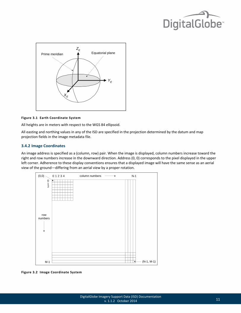
Earth coordinates are expressed relative to an earth-centered fixed (ECF) reference system that rotates with the earth. In particular, all ECF coordinates in ISD files are given in the WGS 84 reference system, including geocentric cartesian coordinates (XE, YE, ZE) and geodetic coordinates (latitude, longitude). The WGS 84 ZE-axis points in the direction of the Conventional Terrestrial Pole (CTP); the XE-axis lies along the intersection of the meridian plane and the CTP equator, pointing outward at Greenwich; the YE-axis completes the right-handed orthogonal coordinate system.
11 DigitalGlobe Imagery Support Data (ISD) Documentation v. 1.1.2 October 2014
Figure 3.1 Earth Coordinate System
All heights are in meters with respect to the WGS 84 ellipsoid.
All easting and northing values in any of the ISD are specified in the projection determined by the datum and map projection fields in the image metadata file.
3.4.2 Image Coordinates
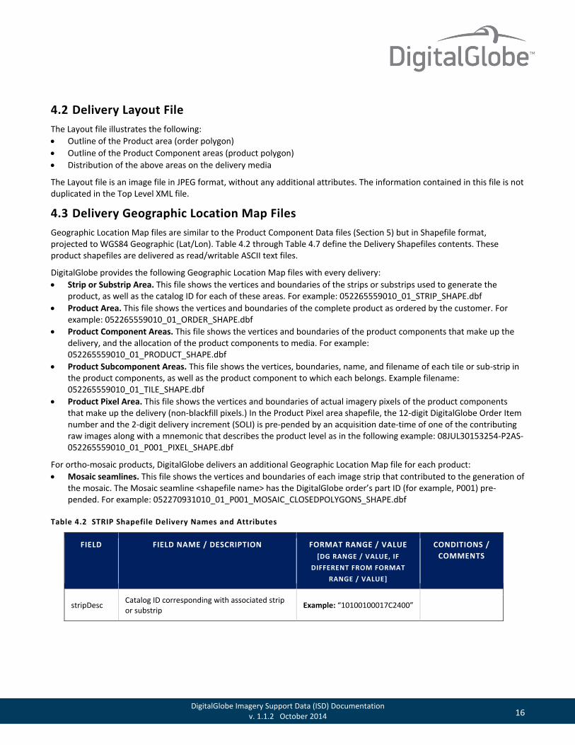
An image address is specified as a (column, row) pair. When the image is displayed, column numbers increase toward the right and row numbers increase in the downward direction. Address (0, 0) corresponds to the pixel displayed in the upper left corner. Adherence to these display conventions ensures that a displayed image will have the same sense as an aerial view of the ground—differing from an aerial view by a proper rotation.
0 1 2 3 N-14 column numbers
012
M-1 (N-1, M-1)
(0,0)
rownumbers
Figure 3.2 Image Coordinate System
YE
ZE
XE
Equatorial planePrime meridian

12 DigitalGlobe Imagery Support Data (ISD) Documentation v. 1.1.2 October 2014
The detector in column 0 of a detector array produces the pixels in column 0 of the corresponding Basic image.
The ground location of a specific pixel in the image is the geolocation of the center of that pixel.
3.4.3 Time
All absolute times are in Coordinated Universal Time (UTC) in the format YYYY-MM-DDThh:mm:ss.ddddddZ.
Relative time offsets from a fixed absolute time are measured in seconds, unless specified otherwise.
An example of both absolute UTC time and relative time is the time-tagged line count (TLC) data in the image metadata file. The TLC data, which are pairs of line numbers and the associated exposure times, provide a way to accurately estimate the time of exposure of any line in the image. The first such timing event for an image is reported in the image metadata file as an absolute UTC time, but subsequent events are reported as time offsets, in seconds, relative to this initial time.

13 DigitalGlobe Imagery Support Data (ISD) Documentation v. 1.1.2 October 2014
4 Delivery Level Support Data 4.1 Delivery Index (README) Contents The Delivery Index contains a list of names of the product files and the Image Support Data (ISD) files, along with copyright information for the entire product delivery. The Delivery Index is found in a Top Level README file and a Top Level XML file delivered with each delivery, and each describes all of the files for all of the products delivered within that delivery. The README file and the XML file contain the same information. The Top Level README File is named for the 12-digit DigitalGlobe Order Item number and the 2-digit delivery increment, for example: 000000077583_01_README.TXT and 000000077583_01_README.XML. Table 4.1 defines the Top Level Delivery Index (README) contents.
Table 4.1 Top-Level Delivery Index (README) Contents (ISDF.DEL.README)
FIELD FIELD NAME / DESCRIPTION
FORMAT RANGE / VALUE [DG RANGE / VALUE, IF DIFFERENT FROM
FORMAT RANGE / VALUE]
CONDITIONS / COMMENTS
version Version of the ISD. “20.0” to “99.99”
copyrightText Copyright and restricted use text.
“Use, duplication or disclosure by the government is subject to the restrictions as set forth in subparagraph (c)(1)(ii) of the Rights in Technical Data and Computer Software Clause contained in D.F.A.R.S. 252.227-7013, and subparagraphs (c)(1) and (2) of the Commercial Computer Software-Restricted Rights contained in 48 C.F.R. 52.227-19. Contractor/manufacturer is DigitalGlobe, Incorporated at 1601 Dry Creek Drive, Suite 260, Longmont, CO 80503-6493. Copyright YYYY DigitalGlobe Incorporated, Longmont CO USA 80503-6493 DigitalGlobe and the DigitalGlobe logo are trademarks of DigitalGlobe, Incorporated. The use and/or dissemination of this data and/or of any product in any way derived there from are restricted. Unauthorized use and/or dissemination is prohibited. DigitalGlobe WWW Reference: http://www.digitalglobe.com”
2nd paragraph Copyright YYYY DigitalGlobe ... Where yyyy is the current year
mediaCreationDate Time of media creation. YYYY-MM-DDThh:mm:ss.dddddZ
The time in this tag has precision to 6 decimal places.
orderNumber
12-digit DigitalGlobe Order Item number, underscore, and 2-digit delivery increment.
“nnnnnnnnnnnn_mm” Example: “052265559010_01”

14 DigitalGlobe Imagery Support Data (ISD) Documentation v. 1.1.2 October 2014
FIELD FIELD NAME / DESCRIPTION
FORMAT RANGE / VALUE [DG RANGE / VALUE, IF DIFFERENT FROM
FORMAT RANGE / VALUE]
CONDITIONS / COMMENTS
fileList A list of all files in the delivery including path directories.
Lists all filenames such as: GIS files Metadata files Product files
This field will vary depending on product type.
areaDesc
Customer supplied description of order. “Null” if no information supplied by the customer.
Example: “IS_05”
dgOrderNo DigitalGlobe Order Number. Example: “052265559”
dgOrderItemNo 12-digit DigitalGlobe Order Item Number. Example: “05226559010”
custOrderNo
Customer supplied order number. ‘Null’ if no information supplied by the customer.
Example: “IS_05”
custOrderItemNo
Customer supplied order item number. ‘Null’ if no information supplied by the customer.
Example: “40005” “40009” “1” “Null”
collectionStart Date of first image acquisition. YYYY-MM-DDThh:mm:ss.ddddddZ
collectionStop Date of final image acquisition. YYYY-MM-DDThh:mm:ss.ddddddZ
countryCode Two letter country code of center point of order polygon.
Example: “ ” Currently blank.
productScale The NMAS mapping scale of Orthorectified Products.
Level 3A: “1:50,000” Level 3D: “1:12,000” Level 3E: “1:10,000” Level 3F: “1:5,000” Level 3G: “1:4,800” Level 3X: “Custom”
Only applicable to Orthorectified (level 3) products.

15 DigitalGlobe Imagery Support Data (ISD) Documentation v. 1.1.2 October 2014
FIELD FIELD NAME / DESCRIPTION
FORMAT RANGE / VALUE [DG RANGE / VALUE, IF DIFFERENT FROM
FORMAT RANGE / VALUE]
CONDITIONS / COMMENTS
numberOfLooks Indicates whether this is a single product or a stereo pair.
“1” for single, “2” for stereo pair
cloudCover
Estimate of the max cloud-covered fraction of the delivery. For mosaic products, this calculation is based on the intersection of the polygons contained in the MOSAIC_CLOSEDPOLYGONS shapefile with the cloud polygons associated with that part of the relevent input imagery.
0.000 to 1.000 Precision: 3 decimal places -999.0 if not assessed
nwLat
Latitude of NW corner of the minimum bounding rectangle (MBR) of the order polygon.
Range: ± 90.00000000 Precision: 8 decimal places
nwLong
Longitude of NW corner of the minimum bounding rectangle (MBR) of the order polygon.
Range: ± 180.00000000 Precision: 8 decimal places
seLat
Latitude of SE corner of the minimum bounding rectangle (MBR) of the order polygon.
Range: ± 90.00000000 Precision: 8 decimal places
seLong
Longitude of SE corner of the minimum bounding rectangle (MBR) of the order polygon.
Range: ± 180.00000000 Precision: 8 decimal places
16 DigitalGlobe Imagery Support Data (ISD) Documentation v. 1.1.2 October 2014
4.2 Delivery Layout File The Layout file illustrates the following: • Outline of the Product area (order polygon) • Outline of the Product Component areas (product polygon) • Distribution of the above areas on the delivery media
The Layout file is an image file in JPEG format, without any additional attributes. The information contained in this file is not duplicated in the Top Level XML file.
4.3 Delivery Geographic Location Map Files Geographic Location Map files are similar to the Product Component Data files (Section 5) but in Shapefile format, projected to WGS84 Geographic (Lat/Lon). Table 4.2 through Table 4.7 define the Delivery Shapefiles contents. These product shapefiles are delivered as read/writable ASCII text files.
DigitalGlobe provides the following Geographic Location Map files with every delivery: • Strip or Substrip Area. This file shows the vertices and boundaries of the strips or substrips used to generate the
product, as well as the catalog ID for each of these areas. For example: 052265559010_01_STRIP_SHAPE.dbf • Product Area. This file shows the vertices and boundaries of the complete product as ordered by the customer. For
example: 052265559010_01_ORDER_SHAPE.dbf • Product Component Areas. This file shows the vertices and boundaries of the product components that make up the
delivery, and the allocation of the product components to media. For example: 052265559010_01_PRODUCT_SHAPE.dbf
• Product Subcomponent Areas. This file shows the vertices, boundaries, name, and filename of each tile or sub-strip in the product components, as well as the product component to which each belongs. Example filename: 052265559010_01_TILE_SHAPE.dbf
• Product Pixel Area. This file shows the vertices and boundaries of actual imagery pixels of the product components that make up the delivery (non-blackfill pixels.) In the Product Pixel area shapefile, the 12-digit DigitalGlobe Order Item number and the 2-digit delivery increment (SOLI) is pre-pended by an acquisition date-time of one of the contributing raw images along with a mnemonic that describes the product level as in the following example: 08JUL30153254-P2AS-052265559010_01_P001_PIXEL_SHAPE.dbf
For ortho-mosaic products, DigitalGlobe delivers an additional Geographic Location Map file for each product: • Mosaic seamlines. This file shows the vertices and boundaries of each image strip that contributed to the generation of
the mosaic. The Mosaic seamline <shapefile name> has the DigitalGlobe order’s part ID (for example, P001) pre-pended. For example: 052270931010_01_P001_MOSAIC_CLOSEDPOLYGONS_SHAPE.dbf
Table 4.2 STRIP Shapefile Delivery Names and Attributes
FIELD FIELD NAME / DESCRIPTION FORMAT RANGE / VALUE [DG RANGE / VALUE, IF
DIFFERENT FROM FORMAT RANGE / VALUE]
CONDITIONS / COMMENTS
stripDesc Catalog ID corresponding with associated strip or substrip Example: “10100100017C2400”

17 DigitalGlobe Imagery Support Data (ISD) Documentation v. 1.1.2 October 2014
FIELD FIELD NAME / DESCRIPTION FORMAT RANGE / VALUE [DG RANGE / VALUE, IF
DIFFERENT FROM FORMAT RANGE / VALUE]
CONDITIONS / COMMENTS
sunAzimuth Azimuth angle of the sun measured from north clockwise, in degrees, at the time the strip or substrip was acquired.
Range: 0.0 – 360.0 Decimal precision may vary.
offNadir
The spacecraft elevation angle measured from nadir to the image center as seen from the spacecraft at the time the strip or substrip was acquired.
Range: ≥ 0.0 Decimal precision may vary.
acquisitio Populated with the strip acquisition date-time. Example: “2002-12-29T15:58:08.626765Z”
Table 4.3 ORDER Shapefile Delivery Names and Attributes
FIELD FIELD NAME / DESCRIPTION
FORMAT RANGE / VALUE [DG RANGE / VALUE, IF DIFFERENT
FROM FORMAT RANGE / VALUE]
CONDITIONS / COMMENTS
orderDesc Item number corresponding with associated order polygon.
Example: “052265559010” This is the 12-digit DigitalGlobe Order Item number. Required, if available.
custOrd Optional order number supplied by the customer at time of order placement.
Example: “IS_46” Only if customer has supplied order number. Required, if available.
custOrdItm Optional order item number supplied by the customer at time of order placement.
Example: “40005” Only if customer has supplied order item. Required, if available.
datum The Datum in which the product was ordered.
“WE” (WGS84) “NAR” (NAD83) “NAS” (NAD27) “TOYM” (Toyko Mean) “GRS80” (GRS80)
Blank for Basic (1B) products.
projection The projection in which the product was ordered.
“UTM” “State Plane Coordinates” “Japan RCS Coordinates” “Geographic (Lat/Long)”
Blank for Basic (1B) products.
createDate Start date of product creation. YYYY-MM-DDThh:mm:ss.ddddddZ

18 DigitalGlobe Imagery Support Data (ISD) Documentation v. 1.1.2 October 2014
Table 4.4 TILE Shapefile Delivery Names and Attributes
FIELD FIELD NAME / DESCRIPTION
FORMAT RANGE / VALUE [DG RANGE / VALUE, IF DIFFERENT FROM
FORMAT RANGE / VALUE]
CONDITIONS / COMMENTS
tileName Tile Name
If R or C ≤ 9: “RnCn” If R or C ≤ 99: “RnnCnn” If R or C ≤ 999: “RnnnCnnn” Examples: “R1C1” “R19C3” RegionTile Example: “iz_20071231_uncl_ci_ 322230n1153730w_imagery.tif”
Rows and Columns do not have to be of the same order of magnitude. For example: A tile of a mosaic with 6 columns and 15 rows would be displayed as: RnnCn
fileName Name of the image file. Example: “02JUN25001236-2AS_R1C1-000000092184_01_P001.NTF”
prodDesc Unique product identifier Example: “P001” Required, if available.
volNum Volume number of the media on which the tile is located.
Example: “Vol. 1”
Table 4.5 PRODUCT Shapefile Delivery Names and Attributes
FIELD FIELD NAME / DESCRIPTION FORMAT RANGE / VALUE [DG RANGE / VALUE, IF DIFFERENT
FROM FORMAT RANGE / VALUE]
CONDITIONS / COMMENTS
prodDesc Unique product identifier Example: “P001”
volNum Volume number of the media on which the tile is located. Example: “Vol. 1-2”
bandInfo Defines type of spectral bands in product. (PanSharp, Multispectral, All Band, Panchromatic).
“PanSharp” “Multispectral” “All Band” “Panchromatic”
19 DigitalGlobe Imagery Support Data (ISD) Documentation v. 1.1.2 October 2014
Table 4.6 PIXEL Shapefile Delivery Names and Attributes
FIELD FIELD NAME / DESCRIPTION FORMAT RANGE / VALUE [DG RANGE / VALUE, IF DIFFERENT FROM
FORMAT RANGE / VALUE]
CONDITIONS / COMMENTS
prodDesc Unique product identifier Example: “3AUG27021804-M2AS-005357007010_01_P001_PIXEL_SHAPE”
volNum Volume number of the media on which the tile is located. Example: “Vol. 1-2”
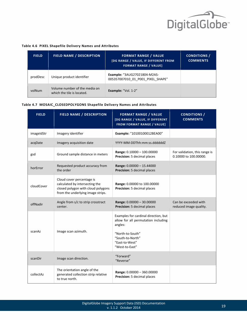
Table 4.7 MOSAIC_CLOSEDPOLYGONS Shapefile Delivery Names and Attributes
FIELD FIELD NAME / DESCRIPTION FORMAT RANGE / VALUE [DG RANGE / VALUE, IF DIFFERENT
FROM FORMAT RANGE / VALUE]
CONDITIONS / COMMENTS
imageIdStr Imagery identifier Example: “10100100012BEA00”
acqDate Imagery acquisition date YYYY-MM-DDThh:mm:ss.ddddddZ
gsd Ground sample distance in meters Range: 0.10000 – 100.00000 Precision: 5 decimal places
For validation, this range is 0.10000 to 100.00000.
horError Requested product accuracy from the order
Range: 0.00000 – 15.44000 Precision: 5 decimal places
cloudCover
Cloud cover percentage is calculated by intersecting the closed polygon with cloud polygons from the underlying image strips.
Range: 0.00000 to 100.00000 Precision: 5 decimal places
offNadir Angle from s/c to strip crosstract center.
Range: 0.00000 – 30.00000 Precision: 5 decimal places
Can be exceeded with reduced image quality.
scanAz Image scan azimuth.
Examples for cardinal direction, but allow for all permutation including angles: “North-to-South” “South-to-North” “East-to-West” “West-to-East”
scanDir Image scan direction. “Forward” “Reverse”
collectAz The orientation angle of the generated collection strip relative to true north.
Range: 0.00000 – 360.00000 Precision: 5 decimal places
20 DigitalGlobe Imagery Support Data (ISD) Documentation v. 1.1.2 October 2014
FIELD FIELD NAME / DESCRIPTION FORMAT RANGE / VALUE [DG RANGE / VALUE, IF DIFFERENT
FROM FORMAT RANGE / VALUE]
CONDITIONS / COMMENTS
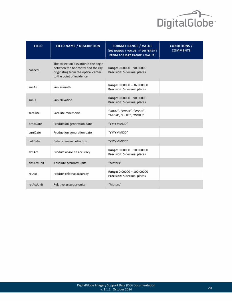
collectEl
The collection elevation is the angle between the horizontal and the ray originating from the optical center to the point of incidence.
Range: 0.00000 – 90.00000 Precision: 5 decimal places
sunAz Sun azimuth. Range: 0.00000 – 360.00000 Precision: 5 decimal places
sunEl Sun elevation. Range: 0.00000 – 90.00000 Precision: 5 decimal places
satellite Satellite mnemonic “QB02”, “WV01”, “WV02”, “Aerial”, “GE01”, “WV03”
prodDate Production generation date “YYYYMMDD”
currDate Production generation date “YYYYMMDD”
collDate Date of image collection “YYYYMMDD”
absAcc Product absolute accuracy Range: 0.00000 – 100.00000 Precision: 5 decimal places
absAccUnit Absolute accuracy units “Meters”
relAcc Product relative accuracy Range: 0.00000 – 100.00000 Precision: 5 decimal places
relAccUnit Relative accuracy units “Meters”
21 DigitalGlobe Imagery Support Data (ISD) Documentation v. 1.1.2 October 2014
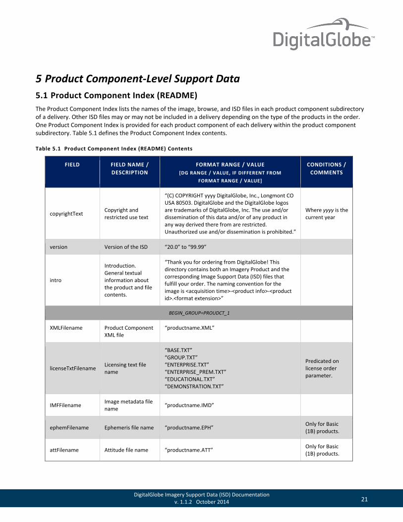
5 Product Component-Level Support Data 5.1 Product Component Index (README) The Product Component Index lists the names of the image, browse, and ISD files in each product component subdirectory of a delivery. Other ISD files may or may not be included in a delivery depending on the type of the products in the order. One Product Component Index is provided for each product component of each delivery within the product component subdirectory. Table 5.1 defines the Product Component Index contents.
Table 5.1 Product Component Index (README) Contents
FIELD FIELD NAME / DESCRIPTION
FORMAT RANGE / VALUE [DG RANGE / VALUE, IF DIFFERENT FROM
FORMAT RANGE / VALUE]
CONDITIONS / COMMENTS
copyrightText Copyright and restricted use text
“(C) COPYRIGHT yyyy DigitalGlobe, Inc., Longmont CO USA 80503. DigitalGlobe and the DigitalGlobe logos are trademarks of DigitalGlobe, Inc. The use and/or dissemination of this data and/or of any product in any way derived there from are restricted. Unauthorized use and/or dissemination is prohibited.”
Where yyyy is the current year
version Version of the ISD “20.0” to “99.99”
intro
Introduction. General textual information about the product and file contents.
“Thank you for ordering from DigitalGlobe! This directory contains both an Imagery Product and the corresponding Image Support Data (ISD) files that fulfill your order. The naming convention for the image is <acquisition time>-<product info>-<product id>.<format extension>”
BEGIN_GROUP=PROUDCT_1
XMLFilename Product Component XML file
“productname.XML”
licenseTxtFilename Licensing text file name
“BASE.TXT” “GROUP.TXT” “ENTERPRISE.TXT” “ENTERPRISE_PREM.TXT” “EDUCATIONAL.TXT” “DEMONSTRATION.TXT”
Predicated on license order parameter.
IMFFilename Image metadata file name “productname.IMD”
ephemFilename Ephemeris file name “productname.EPH” Only for Basic (1B) products.
attFilename Attitude file name “productname.ATT” Only for Basic (1B) products.
22 DigitalGlobe Imagery Support Data (ISD) Documentation v. 1.1.2 October 2014
FIELD FIELD NAME / DESCRIPTION
FORMAT RANGE / VALUE [DG RANGE / VALUE, IF DIFFERENT FROM
FORMAT RANGE / VALUE]
CONDITIONS / COMMENTS
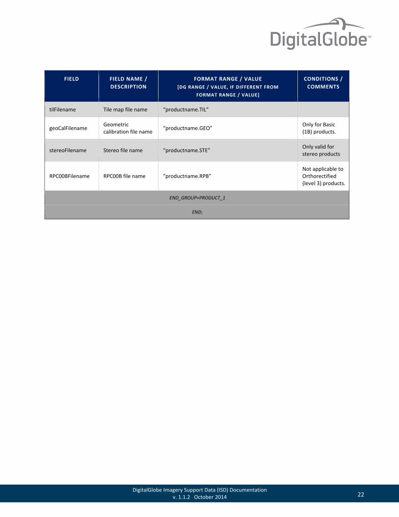
tilFilename Tile map file name “productname.TIL”
geoCalFilename Geometric calibration file name “productname.GEO” Only for Basic
(1B) products.
stereoFilename Stereo file name “productname.STE” Only valid for stereo products
RPC00BFilename RPC00B file name “productname.RPB” Not applicable to Orthorectified (level 3) products.
END_GROUP=PRODUCT_1
END;
23 DigitalGlobe Imagery Support Data (ISD) Documentation v. 1.1.2 October 2014
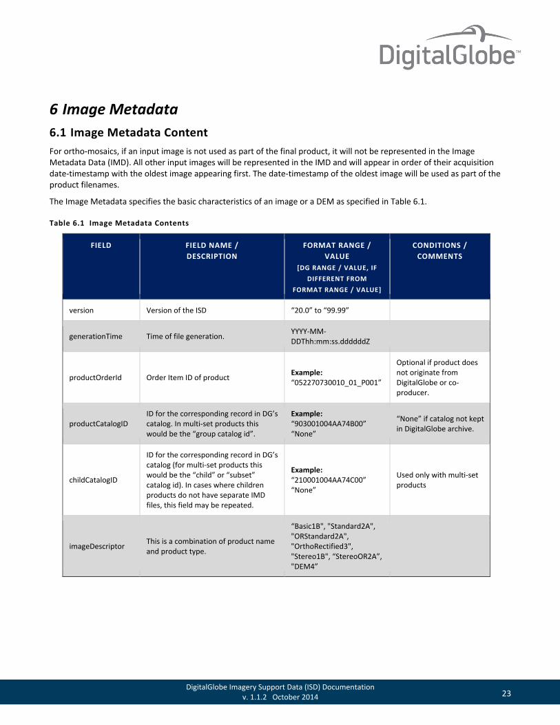
6 Image Metadata 6.1 Image Metadata Content For ortho-mosaics, if an input image is not used as part of the final product, it will not be represented in the Image Metadata Data (IMD). All other input images will be represented in the IMD and will appear in order of their acquisition date-timestamp with the oldest image appearing first. The date-timestamp of the oldest image will be used as part of the product filenames.
The Image Metadata specifies the basic characteristics of an image or a DEM as specified in Table 6.1.
Table 6.1 Image Metadata Contents
FIELD FIELD NAME / DESCRIPTION
FORMAT RANGE / VALUE
[DG RANGE / VALUE, IF DIFFERENT FROM
FORMAT RANGE / VALUE]
CONDITIONS / COMMENTS
version Version of the ISD “20.0” to “99.99”
generationTime Time of file generation. YYYY-MM-DDThh:mm:ss.ddddddZ
productOrderId Order Item ID of product Example: “052270730010_01_P001”
Optional if product does not originate from DigitalGlobe or co-producer.
productCatalogID ID for the corresponding record in DG’s catalog. In multi-set products this would be the “group catalog id”.
Example: “903001004AA74B00” “None”
“None” if catalog not kept in DigitalGlobe archive.
childCatalogID
ID for the corresponding record in DG’s catalog (for multi-set products this would be the “child” or “subset” catalog id). In cases where children products do not have separate IMD files, this field may be repeated.
Example: “210001004AA74C00” “None”
Used only with multi-set products
imageDescriptor This is a combination of product name and product type.
“Basic1B", "Standard2A", "ORStandard2A", "OrthoRectified3", "Stereo1B", “StereoOR2A”, "DEM4”

24 DigitalGlobe Imagery Support Data (ISD) Documentation v. 1.1.2 October 2014
FIELD FIELD NAME / DESCRIPTION
FORMAT RANGE / VALUE
[DG RANGE / VALUE, IF DIFFERENT FROM
FORMAT RANGE / VALUE]
CONDITIONS / COMMENTS
productScale This is the NMAS mapping scale of the Orthorectified Product
Values: Level 3A: “1:50,000” Level 3D: “1:12,000” Level 3E: “1:10,000” Level 3F: “1:5,000” Level 3G: “1:4,800” Level 3X: “Custom”
Only applicable to Orthorectified (level 3) products. For validation purposes, this shoudl be evaluted as a text string tha tis not bound by enumeration.
productAccuracy Identifies the worst case CE90% in meters for the associated productScale.
Values: Level 3A: 25.40 Level 3D: 10.16 Level 3E: 8.47 Level 3F: 4.23 Level 3G: 4.06 “unavailable”
Only applicable to Orthorectified (level 3) products. For validation purposes, the actuals may range from 0.1 to 100.00.
RMSE2D Two Dimensional Root Mean Square Error
Values: Level 3A: 15.44 Level 3D: 6.18 Level 3E: 5.15 Level 3F: 2.57 Level 3G: 2.47 Level 3X: 0.00 Precision: 2 decimal places
Only applicable for Orthorectified (level 3) products. Level 3X uses customer supplied data. For example, DEM(s), GCPs or both. Therefore, DG does not guarantee accuracy. For validation purposes, the actual values range from 0.1 to 99.00.
25 DigitalGlobe Imagery Support Data (ISD) Documentation v. 1.1.2 October 2014
FIELD FIELD NAME / DESCRIPTION
FORMAT RANGE / VALUE
[DG RANGE / VALUE, IF DIFFERENT FROM
FORMAT RANGE / VALUE]
CONDITIONS / COMMENTS
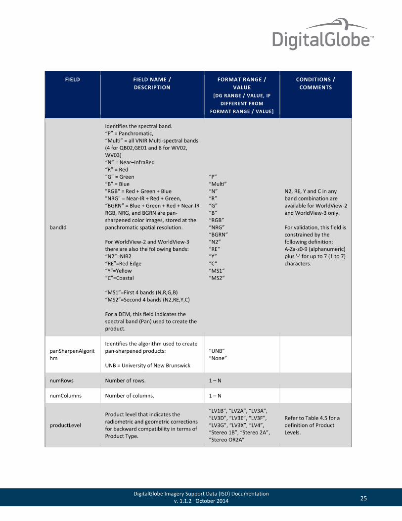
bandId
Identifies the spectral band. “P” = Panchromatic, “Multi” = all VNIR Multi-spectral bands (4 for QB02,GE01 and 8 for WV02, WV03) “N” = Near–InfraRed “R” = Red “G” = Green “B” = Blue "RGB" = Red + Green + Blue "NRG" = Near-IR + Red + Green, “BGRN” = Blue + Green + Red + Near-IR RGB, NRG, and BGRN are pan-sharpened color images, stored at the panchromatic spatial resolution. For WorldView-2 and WorldView-3 there are also the following bands: “N2”=NIR2 “RE”=Red Edge “Y”=Yellow “C”=Coastal “MS1”=First 4 bands (N,R,G,B) “MS2”=Second 4 bands (N2,RE,Y,C) For a DEM, this field indicates the spectral band (Pan) used to create the product.
“P” “Multi” “N” “R” “G” “B” “RGB” “NRG” “BGRN” “N2“ “RE“ “Y“ “C“ “MS1“ “MS2“
N2, RE, Y and C in any band combination are available for WorldView-2 and WorldView-3 only. For validation, this field is constrained by the following definition: A-Za-z0-9 (alphanumeric) plus '-' for up to 7 (1 to 7) characters.
panSharpenAlgorithm
Identifies the algorithm used to create pan-sharpened products: UNB = University of New Brunswick
“UNB” “None”
numRows Number of rows. 1 – N
numColumns Number of columns. 1 – N
productLevel
Product level that indicates the radiometric and geometric corrections for backward compatibility in terms of Product Type.
“LV1B”, “LV2A”, “LV3A”, “LV3D”, “LV3E”, “LV3F”, “LV3G”, “LV3X”, “LV4”, “Stereo 1B”, “Stereo 2A”, “Stereo OR2A”
Refer to Table 4.5 for a definition of Product Levels.
26 DigitalGlobe Imagery Support Data (ISD) Documentation v. 1.1.2 October 2014
FIELD FIELD NAME / DESCRIPTION
FORMAT RANGE / VALUE
[DG RANGE / VALUE, IF DIFFERENT FROM
FORMAT RANGE / VALUE]
CONDITIONS / COMMENTS
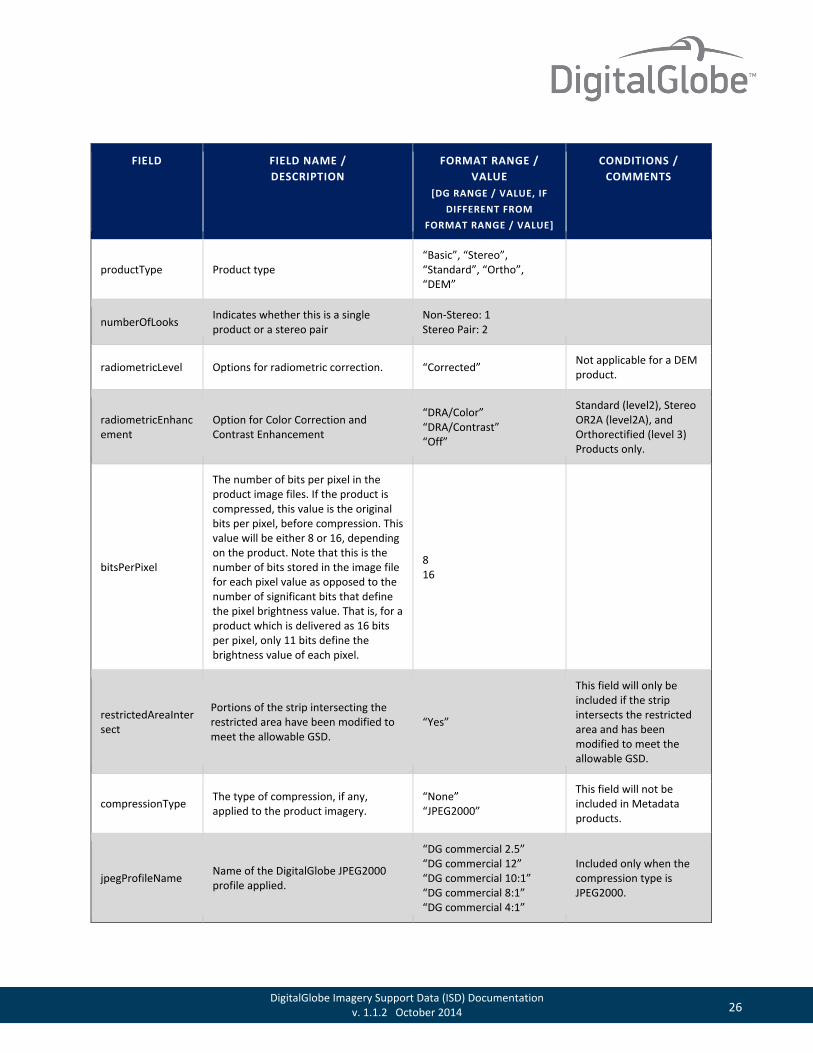
productType Product type “Basic”, “Stereo”, “Standard”, “Ortho”, “DEM”
numberOfLooks Indicates whether this is a single product or a stereo pair
Non-Stereo: 1 Stereo Pair: 2
radiometricLevel Options for radiometric correction. “Corrected” Not applicable for a DEM product.
radiometricEnhancement
Option for Color Correction and Contrast Enhancement
“DRA/Color” “DRA/Contrast” “Off”
Standard (level2), Stereo OR2A (level2A), and Orthorectified (level 3) Products only.
bitsPerPixel
The number of bits per pixel in the product image files. If the product is compressed, this value is the original bits per pixel, before compression. This value will be either 8 or 16, depending on the product. Note that this is the number of bits stored in the image file for each pixel value as opposed to the number of significant bits that define the pixel brightness value. That is, for a product which is delivered as 16 bits per pixel, only 11 bits define the brightness value of each pixel.
8 16
restrictedAreaIntersect
Portions of the strip intersecting the restricted area have been modified to meet the allowable GSD.
“Yes”
This field will only be included if the strip intersects the restricted area and has been modified to meet the allowable GSD.
compressionType The type of compression, if any, applied to the product imagery.
“None” “JPEG2000”
This field will not be included in Metadata products.
jpegProfileName Name of the DigitalGlobe JPEG2000 profile applied.
“DG commercial 2.5” “DG commercial 12” “DG commercial 10:1” “DG commercial 8:1” “DG commercial 4:1”
Included only when the compression type is JPEG2000.

27 DigitalGlobe Imagery Support Data (ISD) Documentation v. 1.1.2 October 2014
FIELD FIELD NAME / DESCRIPTION
FORMAT RANGE / VALUE
[DG RANGE / VALUE, IF DIFFERENT FROM
FORMAT RANGE / VALUE]
CONDITIONS / COMMENTS
The following group is repeated for each spectral band in the delivered image product. The index b in the group name is one of (P,N,R,G,B, N2,RE,Y,C) to differentiate the band group names. In this group, latitudes (Lat) and longitudes (Lon) are in degrees and heights above the
WGS 84 ellipsoid (HAE) are in meters.
BEGIN_GROUP=BAND_b
ULLon Geodetic longitude of the upper left pixel of the image.
Range: ± 180.00000000 Precision: 8 decimal places
ULLat Geodetic latitude of the upper left pixel of the image.
Range: ± 90.00000000 Precision: 8 decimal places
ULHAE Height above the ellipse of the upper left pixel of the image. Precision: 2 decimal places
URLon Geodetic longitude of the upper right pixel of the image.
Range: ± 180.00000000 Precision: 8 decimal places
URLat Geodetic latitude of the upper right pixel of the image.
Range: ± 90.00000000 Precision: 8 decimal places
URHAE Height above the ellipse of the upper right pixel of the image. Precision: 2 decimal places
LRLon Geodetic longitude of the lower right pixel of the image.
Range: ± 180.00000000 Precision: 8 decimal places
LRLat Geodetic latitude of the lower right pixel of the image.
Range: ± 90.00000000 Precision: 8 decimal places
LRHAE Height above the ellipse of the lower right pixel of the image. Precision: 2 decimal places
LLLon Geodetic longitude of the lower left pixel of the image.
Range: ± 180.00000000 Precision: 8 decimal places
LLLat Geodetic latitude of the lower left pixel of the image.
Range: ± 90.00000000 Precision: 8 decimal places
LLHAE Height above the ellipse of the lower left pixel of the image. Precision: 2 decimal places
28 DigitalGlobe Imagery Support Data (ISD) Documentation v. 1.1.2 October 2014
FIELD FIELD NAME / DESCRIPTION
FORMAT RANGE / VALUE
[DG RANGE / VALUE, IF DIFFERENT FROM
FORMAT RANGE / VALUE]
CONDITIONS / COMMENTS
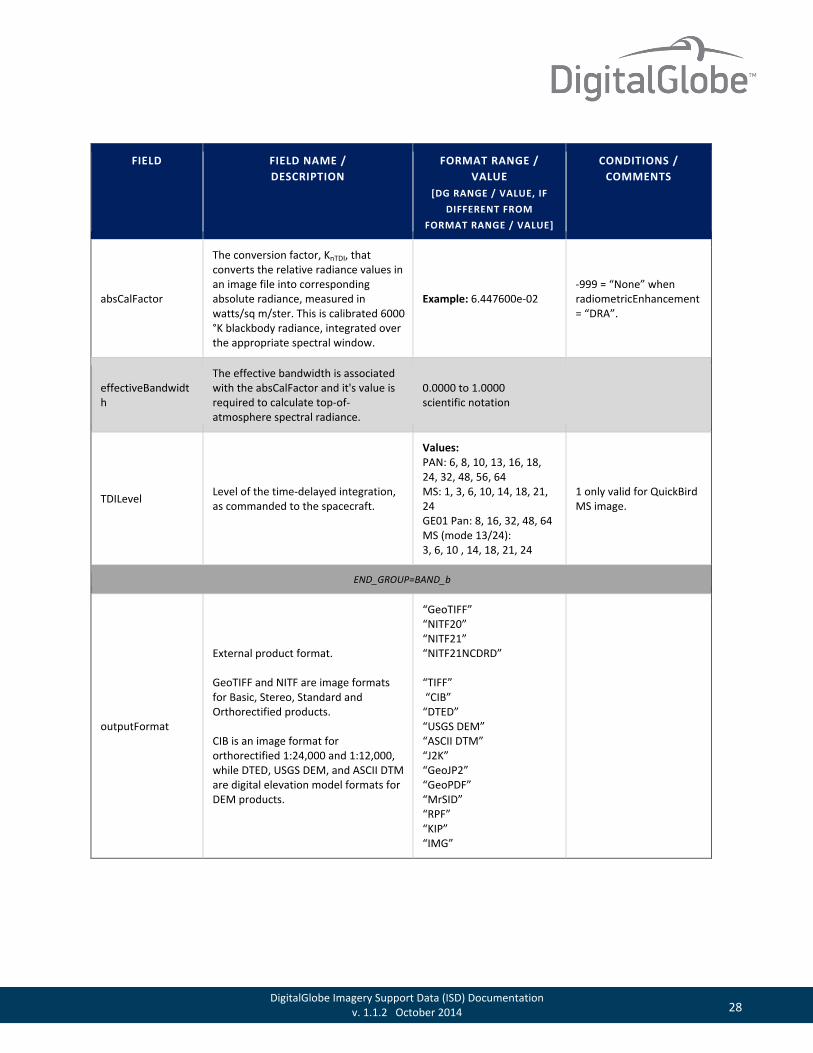
absCalFactor
The conversion factor, KnTDI, that converts the relative radiance values in an image file into corresponding absolute radiance, measured in watts/sq m/ster. This is calibrated 6000 °K blackbody radiance, integrated over the appropriate spectral window.
Example: 6.447600e-02 -999 = “None” when radiometricEnhancement = “DRA”.
effectiveBandwidth
The effective bandwidth is associated with the absCalFactor and it's value is required to calculate top-of-atmosphere spectral radiance.
0.0000 to 1.0000 scientific notation
TDILevel Level of the time-delayed integration, as commanded to the spacecraft.
Values: PAN: 6, 8, 10, 13, 16, 18, 24, 32, 48, 56, 64 MS: 1, 3, 6, 10, 14, 18, 21, 24 GE01 Pan: 8, 16, 32, 48, 64 MS (mode 13/24): 3, 6, 10 , 14, 18, 21, 24
1 only valid for QuickBird MS image.
END_GROUP=BAND_b
outputFormat
External product format. GeoTIFF and NITF are image formats for Basic, Stereo, Standard and Orthorectified products. CIB is an image format for orthorectified 1:24,000 and 1:12,000, while DTED, USGS DEM, and ASCII DTM are digital elevation model formats for DEM products.
“GeoTIFF” “NITF20” “NITF21” “NITF21NCDRD” “TIFF” “CIB” “DTED” “USGS DEM” “ASCII DTM” “J2K” “GeoJP2” “GeoPDF” “MrSID” “RPF” “KIP” “IMG”

29 DigitalGlobe Imagery Support Data (ISD) Documentation v. 1.1.2 October 2014
FIELD FIELD NAME / DESCRIPTION
FORMAT RANGE / VALUE
[DG RANGE / VALUE, IF DIFFERENT FROM
FORMAT RANGE / VALUE]
CONDITIONS / COMMENTS
The following group is repeated for each n = 1,…,numImagesInProduct. That is, for all images used to create the image product. For single image products (Basic) there is one .IMD file per source image or strip, so the group will appear only once for each product component. For multiple image products (Stereo, Standard, and Orthorectified), the following group will be repeated for each source image in the image product. The index “n” in the group name is a sequential number of the image used to produce the product (1,2,3,…,n) to differentiate the image group names. The image with the earliest aquisition time will be assigned n = 1, and incremented in ascending order.
BEGIN_GROUP=IMAGE_n
satId Satellite Id. “QB02”, “WV01”, “WV02”, “GE01”, “WV03”
mode Sensor Mode. “FullSwath”, “CenterSwath”
Only “FullSwath” for QuickBird.
scanDirection Sensor scan direction. “Forward”, “Reverse” Only “Forward” for QuickBird
CatId
DigitalGlobe catalog Id for the raw data used in this product. For mosaics, only strips used in the mosaic creation should be listed. The catalog ids are ordered from earliest aquisition to latest.
Example: “1020010007AF7100”
For each sub-strip or area based product.
TLCTime Absolute time of the first time-tagged line count record, used in the product component.
YYYY-MM-DDThh:mm:ss.ddddddZ
Only for Level 1B products.
numTLC Number of time-tagged line count records in the TLCList used in the product component.
Range: ≥ 1 Only for Level 1B products.

30 DigitalGlobe Imagery Support Data (ISD) Documentation v. 1.1.2 October 2014
FIELD FIELD NAME / DESCRIPTION
FORMAT RANGE / VALUE
[DG RANGE / VALUE, IF DIFFERENT FROM
FORMAT RANGE / VALUE]
CONDITIONS / COMMENTS
TLCList
List of time-tagged line count (TLC) records. Each TLC record consists of lineNumber (Short) timeOffset (Float) lineNumber is the image line number for a line in the product component. This number will be negative if the TLC record precedes the product component. timeOffset is the recorded time tag for this line, in seconds after TLCTime. The timeOffset will be negative if the image is in the reverse scan direction.
Example: ( (-256, 0.000000) , (768, 0.148404), ... (N, N.nnnnnn) ) Precision: TLCTime will have 6 decimal places precision.
Only for Level 1B products.
firstLineTime Exposure time for the first line in the strip used for the product component.
YYYY-MM-DDThh:mm:ss.ddddddZ
avgLineRate Average number of image lines exposed per second. Precision: 2 decimal places
For Pan-Sharpened products, this will be equal to the average MS line rate.
exposureDuration Duration of the exposure interval for each line.
Value: 1/avgLineRate for VNIR Precision: up to 9 decimal places
Precision may not run to 9 if there are trailing zeroes.
minCollectedRowGSD
Minimum original collected GSD of the product in the row direction.
Range: 0.100-100.000 Precision: 3 decimal places The Pan GSD is used for
Panchromatic and Pan-sharpened products; the MS GSD is used for MS products. These value ranges are based on 0 to 45 degrees off nadir for all sensors with regard to VNIR. For validation all GSD values will range from 0.1 to 100.000 which allows for a range of subsampling.
maxCollectedRowGSD
Maximum original collected GSD of the product in the row direction.
Range: 0.100-100.000 Precision: 3 decimal places
meanCollectedRowGSD
Mean original collected GSD of the product in the row direction.
Range: 0.100-100.000 Precision: 3 decimal places
minCollectedColGSD
Minimum original collected GSD of the product in the column direction.
Range: 0.100-100.000 Precision: 3 decimal places
maxCollectedColGSD
Maximum original collected GSD of the product in the column direction.
Range: 0.100-100.000 Precision: 3 decimal places
meanCollectedColGSD
Mean original collected GSD of the product in the column direction.
Range: 0.100-100.000 Precision: 3 decimal places

31 DigitalGlobe Imagery Support Data (ISD) Documentation v. 1.1.2 October 2014
FIELD FIELD NAME / DESCRIPTION
FORMAT RANGE / VALUE
[DG RANGE / VALUE, IF DIFFERENT FROM
FORMAT RANGE / VALUE]
CONDITIONS / COMMENTS
meanCollectedGSD Mean GSD of the original, collected row and column GSD.
Range: 0.100-100.000 Precision: 3 decimal places
meanProductRowGSD
Mean GSD of the product in the row direction.
Range: 0.100-100.000 Precision: 3 decimal places
Applicable to Level 1B products only.
meanProductColGSD
Mean GSD of the product in the column direction.
Range: 0.100-100.000 Precision: 3 decimal places
Applicable to Level 1B products only.
meanProductGSD Mean GSD of the product row and column GSD.
Range: 0.100-100.000 Precision: 3 decimal places
Applicable to Level 1B products only.
rowUncertainty Mean position uncertainty in line and pixel directions. These are 3-sigma, one-dimensional values.
Precision: 2 decimal places
colUncertainty Mean position uncertainty in line and pixel directions These are 3-sigma, one-dimensional values.
Precision: 2 decimal places
minSunAz Minimum azimuth angle of the sun measured from north clockwise.
Range: 0.0 to 360.0 Precision: One decimal point
maxSunAz Maximum azimuth angle of the sun measured from north clockwise.
Range: 0.0 to 360.0 Precision: One decimal point
meanSunAz Mean azimuth angle of the sun measured from north clockwise.
Range: 0.0 to 360.0 Precision: One decimal point
minSunEl Minimum elevation angle of the sun from horizontal.
Range: ± 90.0 Precision: One decimal point
maxSunEl Maximum elevation angle of the sun from horizontal.
Range: ± 90.0 Precision: One decimal point
meanSunEl Mean elevation angle of the sun from horizontal.
Range: ± 90.0 Precision: One decimal point
32 DigitalGlobe Imagery Support Data (ISD) Documentation v. 1.1.2 October 2014
FIELD FIELD NAME / DESCRIPTION
FORMAT RANGE / VALUE
[DG RANGE / VALUE, IF DIFFERENT FROM
FORMAT RANGE / VALUE]
CONDITIONS / COMMENTS
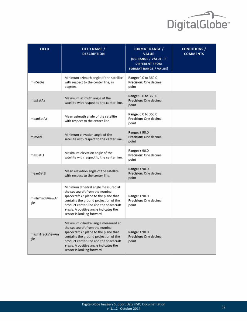
minSatAz Minimum azimuth angle of the satellite with respect to the center line, in degrees.
Range: 0.0 to 360.0 Precision: One decimal point
maxSatAz Maximum azimuth angle of the satellite with respect to the center line.
Range: 0.0 to 360.0 Precision: One decimal point
meanSatAz Mean azimuth angle of the satellite with respect to the center line.
Range: 0.0 to 360.0 Precision: One decimal point
minSatEl Minimum elevation angle of the satellite with respect to the center line.
Range: ± 90.0 Precision: One decimal point
maxSatEl Maximum elevation angle of the satellite with respect to the center line.
Range: ± 90.0 Precision: One decimal point
meanSatEl Mean elevation angle of the satellite with respect to the center line.
Range: ± 90.0 Precision: One decimal point
minInTrackViewAngle
Minimum dihedral angle measured at the spacecraft from the nominal spacecraft YZ plane to the plane that contains the ground projection of the product center-line and the spacecraft Y-axis. A positive angle indicates the sensor is looking forward.
Range: ± 90.0 Precision: One decimal point
maxInTrackViewAngle
Maximum dihedral angle measured at the spacecraft from the nominal spacecraft YZ plane to the plane that contains the ground projection of the product center-line and the spacecraft Y-axis. A positive angle indicates the sensor is looking forward.
Range: ± 90.0 Precision: One decimal point

33 DigitalGlobe Imagery Support Data (ISD) Documentation v. 1.1.2 October 2014
FIELD FIELD NAME / DESCRIPTION
FORMAT RANGE / VALUE
[DG RANGE / VALUE, IF DIFFERENT FROM
FORMAT RANGE / VALUE]
CONDITIONS / COMMENTS
meanInTrackViewAngle
Mean dihedral angle measured at the spacecraft from the nominal spacecraft YZ plane to the plane that contains the ground projection of the product center-line and the spacecraft Y-axis. A positive angle indicates the sensor is looking forward.
Range: ± 90.0 Precision: One decimal point
minCrossTrackViewAngle
Minimum dihedral angle measured at the spacecraft from the nominal spacecraft XZ plane to the plane that contains the ground projection of the product center-line and the spacecraft X-axis. A positive angle indicates the sensor is looking to the right.
Range: ± 90.0 Precision: One decimal point
maxCrossTrackViewAngle
Maximum dihedral angle measured at the spacecraft from the nominal spacecraft XZ plane to the plane that contains the ground projection of the product center-line and the spacecraft X-axis. A positive angle indicates the sensor is looking to the right.
Range: ± 90.0 Precision: One decimal point
meanCrossTrackViewAngle
Mean dihedral angle measured at the spacecraft from the nominal spacecraft XZ plane to the plane that contains the ground projection of the product center-line and the spacecraft X-axis. A positive angle indicates the sensor is looking to the right.
Range: ± 90.0 Precision: One decimal point
minOffNadirViewAngle
The minimum spacecraft elevation angle measured from nadir to the product center-line as seen from the spacecraft.
Range: 0.0 to 90.0 Precision: One decimal place
maxOffNadirViewAngle
The maximum spacecraft elevation angle measured from nadir to the product center-line as seen from the spacecraft.
Range: 0.0 to 90.0 Precision: One decimal place

34 DigitalGlobe Imagery Support Data (ISD) Documentation v. 1.1.2 October 2014
FIELD FIELD NAME / DESCRIPTION
FORMAT RANGE / VALUE
[DG RANGE / VALUE, IF DIFFERENT FROM
FORMAT RANGE / VALUE]
CONDITIONS / COMMENTS
meanOffNadirViewAngle
The mean spacecraft elevation angle measured from nadir to the product center-line as seen from the spacecraft.
Range: 0.0 to 90.0 Precision: One decimal place
PNIIRS
Mean predicted image quality on the National Imagery Interpretability Rating Scale (NIIRS), as computed by the General Image Quality Equation (GIQE).
0.0 to 9.0
cloudCover
Estimate of the max cloud-covered fraction of the product component. . For mosaic products, this calculation is based on the intersection of the polygons contained in the MOSAIC_CLOSEDPOLYGONS shapefile with the cloud polygons associated with that part of the relevent input imagery.
0.000 to 1.000 -999.000 -999.000 if not assessed
resamplingKernel
Method used to resample the image. ”NULL”=no resampling kernel “NN”=nearest neighbor “CC”=cubic convolution “MTF”=Modulation Transfer Function “PS”=Pan sharpening “ENH”=Enhanced (Boost) kernel “UserDefined”
“NULL” “NN” “CC” “MTF” “PS” “ENH” “UserDefined”
Only valid when doing radiometric correction.
positionKnowledgeSrc
Source of knowledge of the satellite position. “R” = Refined
“R”
attitudeKnowledgeSrc
Source of knowledge of the satellite attitude. “R” = Refined
“R”
revNumber Orbit revolution number at the time of exposure. Range: 1 to 99999
BEGIN_GROUP=IMAGE_n
BEGIN_GROUP=MAP_PROJECTED_PRODUCT Only for map-projected
(LV2A, LV3 and DEM) and Stereo OR2A products.
35 DigitalGlobe Imagery Support Data (ISD) Documentation v. 1.1.2 October 2014
FIELD FIELD NAME / DESCRIPTION
FORMAT RANGE / VALUE
[DG RANGE / VALUE, IF DIFFERENT FROM
FORMAT RANGE / VALUE]
CONDITIONS / COMMENTS
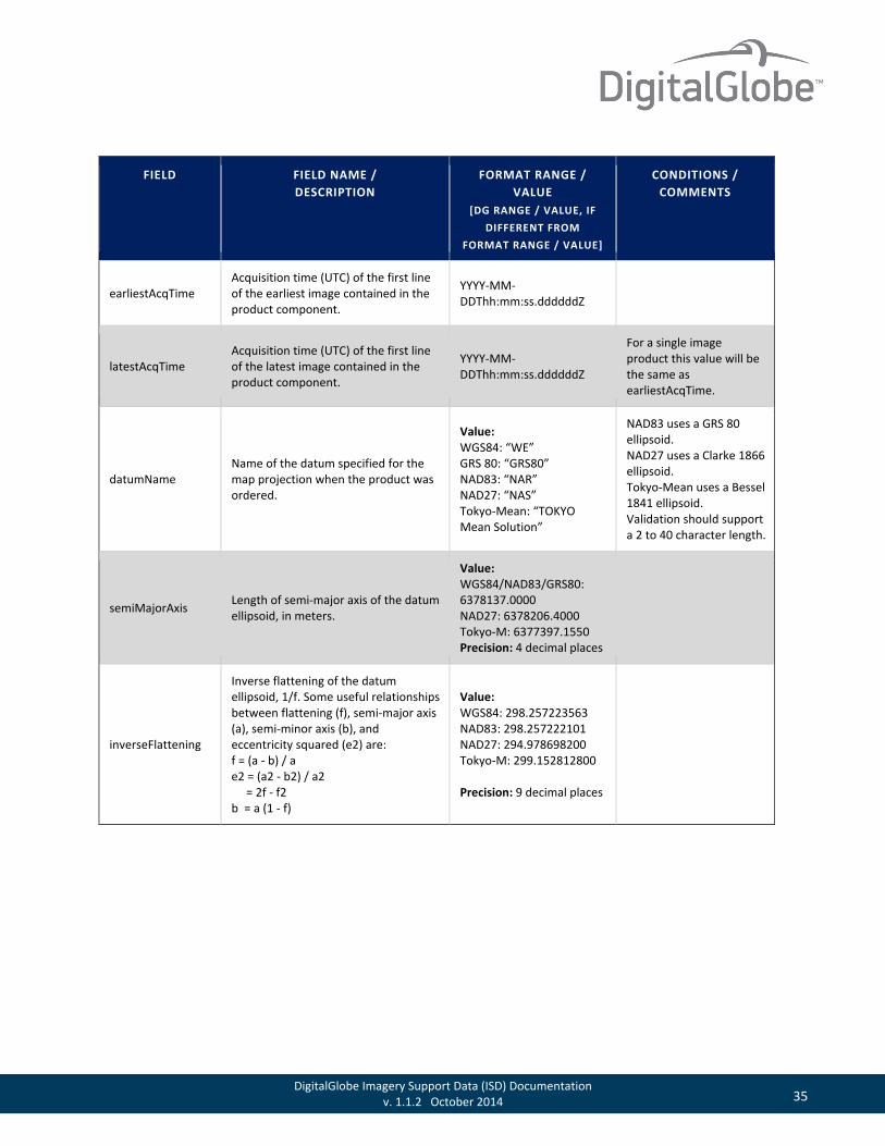
earliestAcqTime Acquisition time (UTC) of the first line of the earliest image contained in the product component.
YYYY-MM-DDThh:mm:ss.ddddddZ
latestAcqTime Acquisition time (UTC) of the first line of the latest image contained in the product component.
YYYY-MM-DDThh:mm:ss.ddddddZ
For a single image product this value will be the same as earliestAcqTime.
datumName Name of the datum specified for the map projection when the product was ordered.
Value: WGS84: “WE” GRS 80: “GRS80” NAD83: “NAR” NAD27: “NAS” Tokyo-Mean: “TOKYO Mean Solution”
NAD83 uses a GRS 80 ellipsoid. NAD27 uses a Clarke 1866 ellipsoid. Tokyo-Mean uses a Bessel 1841 ellipsoid. Validation should support a 2 to 40 character length.
semiMajorAxis Length of semi-major axis of the datum ellipsoid, in meters.
Value: WGS84/NAD83/GRS80: 6378137.0000 NAD27: 6378206.4000 Tokyo-M: 6377397.1550 Precision: 4 decimal places
inverseFlattening
Inverse flattening of the datum ellipsoid, 1/f. Some useful relationships between flattening (f), semi-major axis (a), semi-minor axis (b), and eccentricity squared (e2) are: f = (a - b) / a e2 = (a2 - b2) / a2 = 2f - f2 b = a (1 - f)
Value: WGS84: 298.257223563 NAD83: 298.257222101 NAD27: 294.978698200 Tokyo-M: 299.152812800 Precision: 9 decimal places
36 DigitalGlobe Imagery Support Data (ISD) Documentation v. 1.1.2 October 2014
FIELD FIELD NAME / DESCRIPTION
FORMAT RANGE / VALUE
[DG RANGE / VALUE, IF DIFFERENT FROM
FORMAT RANGE / VALUE]
CONDITIONS / COMMENTS
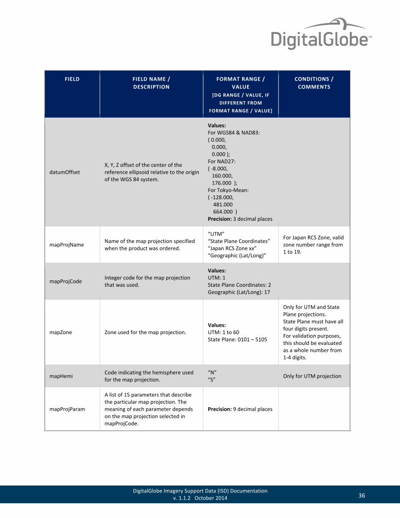
datumOffset X, Y, Z offset of the center of the reference ellipsoid relative to the origin of the WGS 84 system.
Values: For WGS84 & NAD83: ( 0.000, 0.000, 0.000 ); For NAD27: ( -8.000, 160.000, 176.000 ); For Tokyo-Mean: ( -128.000, 481.000 664.000 ) Precision: 3 decimal places
mapProjName Name of the map projection specified when the product was ordered.
“UTM” “State Plane Coordinates” “Japan RCS Zone xx” “Geographic (Lat/Long)”
For Japan RCS Zone, valid zone number range from 1 to 19.
mapProjCode Integer code for the map projection that was used.
Values: UTM: 1 State Plane Coordinates: 2 Geographic (Lat/Long): 17
mapZone Zone used for the map projection. Values: UTM: 1 to 60 State Plane: 0101 – 5105
Only for UTM and State Plane projections. State Plane must have all four digits present. For validation purposes, this should be evaluated as a whole number from 1-4 digits.
mapHemi Code indicating the hemisphere used for the map projection.
“N” “S” Only for UTM projection
mapProjParam
A list of 15 parameters that describe the particular map projection. The meaning of each parameter depends on the map projection selected in mapProjCode.
Precision: 9 decimal places

37 DigitalGlobe Imagery Support Data (ISD) Documentation v. 1.1.2 October 2014
FIELD FIELD NAME / DESCRIPTION
FORMAT RANGE / VALUE
[DG RANGE / VALUE, IF DIFFERENT FROM
FORMAT RANGE / VALUE]
CONDITIONS / COMMENTS
productUnits Units of projected product
Precision: “DD” = Decimal Degrees “M” = Meters “F” = Feet “USF” = US Survey Feet
originX Easting of the center of the upper left pixel of the image. Precision: 8 decimal places
This is equal to ULX unless an origin is specified by the customer.
originY Northing of the center of the upper left pixel of the image. Precision: 8 decimal places
This is equal to ULY unless an origin is specified by the customer.
orientationAngle
Azimuth angle measured clockwise from map north to the “up” direction at the center of the image. This is a rotation between raster image and the map coordinate systems. Since map-projected products are always Map-North up, this is always zero.
0.0
colSpacing GSD of the image in the column direction.
Values: colSpacing: 2 decimal places for non-geographic projected products colSpacing: scientific notation for geographic projected products
Not applicable to DEMs.
rowSpacing GSD of the image in the row direction.
Values: rowSpacing: 2 decimal places for non-geographic projected products rowSpacing: scientific notation for geographic projected products
Not applicable to DEMs.
38 DigitalGlobe Imagery Support Data (ISD) Documentation v. 1.1.2 October 2014
FIELD FIELD NAME / DESCRIPTION
FORMAT RANGE / VALUE
[DG RANGE / VALUE, IF DIFFERENT FROM
FORMAT RANGE / VALUE]
CONDITIONS / COMMENTS
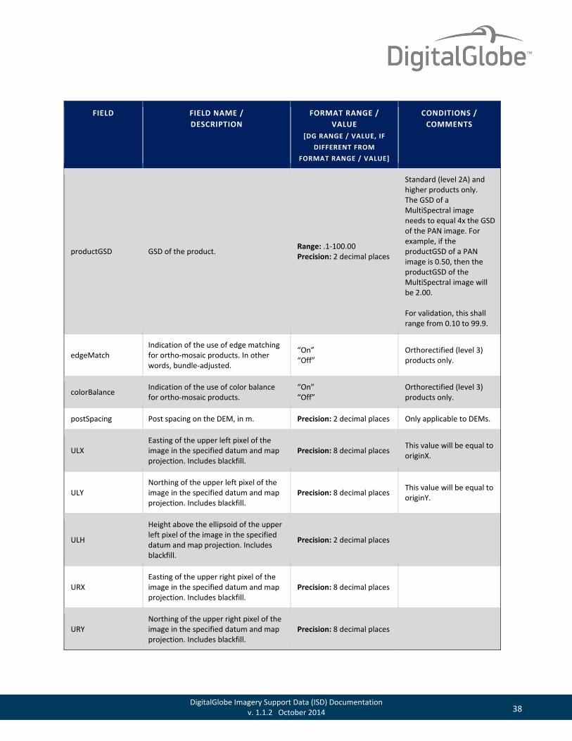
productGSD GSD of the product. Range: .1-100.00 Precision: 2 decimal places
Standard (level 2A) and higher products only. The GSD of a MultiSpectral image needs to equal 4x the GSD of the PAN image. For example, if the productGSD of a PAN image is 0.50, then the productGSD of the MultiSpectral image will be 2.00. For validation, this shall range from 0.10 to 99.9.
edgeMatch Indication of the use of edge matching for ortho-mosaic products. In other words, bundle-adjusted.
“On” “Off”
Orthorectified (level 3) products only.
colorBalance Indication of the use of color balance for ortho-mosaic products.
“On” “Off”
Orthorectified (level 3) products only.
postSpacing Post spacing on the DEM, in m. Precision: 2 decimal places Only applicable to DEMs.
ULX Easting of the upper left pixel of the image in the specified datum and map projection. Includes blackfill.
Precision: 8 decimal places This value will be equal to originX.
ULY Northing of the upper left pixel of the image in the specified datum and map projection. Includes blackfill.
Precision: 8 decimal places This value will be equal to originY.
ULH
Height above the ellipsoid of the upper left pixel of the image in the specified datum and map projection. Includes blackfill.
Precision: 2 decimal places
URX Easting of the upper right pixel of the image in the specified datum and map projection. Includes blackfill.
Precision: 8 decimal places
URY Northing of the upper right pixel of the image in the specified datum and map projection. Includes blackfill.
Precision: 8 decimal places
39 DigitalGlobe Imagery Support Data (ISD) Documentation v. 1.1.2 October 2014
FIELD FIELD NAME / DESCRIPTION
FORMAT RANGE / VALUE
[DG RANGE / VALUE, IF DIFFERENT FROM
FORMAT RANGE / VALUE]
CONDITIONS / COMMENTS
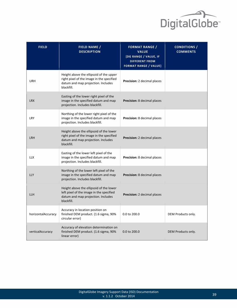
URH
Height above the ellipsoid of the upper right pixel of the image in the specified datum and map projection. Includes blackfill.
Precision: 2 decimal places
LRX Easting of the lower right pixel of the image in the specified datum and map projection. Includes blackfill.
Precision: 8 decimal places
LRY Northing of the lower right pixel of the image in the specified datum and map projection. Includes blackfill.
Precision: 8 decimal places
LRH
Height above the ellipsoid of the lower right pixel of the image in the specified datum and map projection. Includes blackfill.
Precision: 2 decimal places
LLX Easting of the lower left pixel of the image in the specified datum and map projection. Includes blackfill.
Precision: 8 decimal places
LLY Northing of the lower left pixel of the image in the specified datum and map projection. Includes blackfill.
Precision: 8 decimal places
LLH
Height above the ellipsoid of the lower left pixel of the image in the specified datum and map projection. Includes blackfill.
Precision: 2 decimal places
horizontalAccuracy Accuracy in location position on finished DEM product. (1.6 sigma, 90% circular error)
0.0 to 200.0 DEM Products only.
verticalAccuracy Accuracy of elevation determination on finished DEM product. (1.6 sigma, 90% linear error)
0.0 to 200.0 DEM Products only.
40 DigitalGlobe Imagery Support Data (ISD) Documentation v. 1.1.2 October 2014
FIELD FIELD NAME / DESCRIPTION
FORMAT RANGE / VALUE
[DG RANGE / VALUE, IF DIFFERENT FROM
FORMAT RANGE / VALUE]
CONDITIONS / COMMENTS
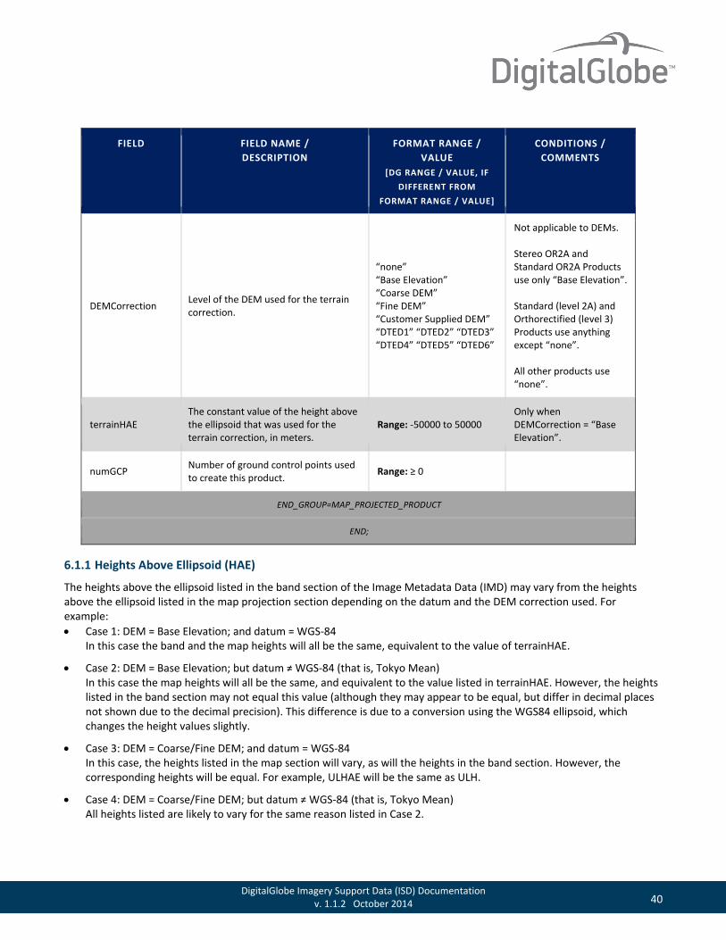
DEMCorrection Level of the DEM used for the terrain correction.
“none” “Base Elevation” “Coarse DEM” “Fine DEM” “Customer Supplied DEM” “DTED1” “DTED2” “DTED3” “DTED4” “DTED5” “DTED6”
Not applicable to DEMs. Stereo OR2A and Standard OR2A Products use only “Base Elevation”. Standard (level 2A) and Orthorectified (level 3) Products use anything except “none”. All other products use “none”.
terrainHAE The constant value of the height above the ellipsoid that was used for the terrain correction, in meters.
Range: -50000 to 50000 Only when DEMCorrection = “Base Elevation”.
numGCP Number of ground control points used to create this product. Range: ≥ 0
END_GROUP=MAP_PROJECTED_PRODUCT
END;
6.1.1 Heights Above Ellipsoid (HAE)
The heights above the ellipsoid listed in the band section of the Image Metadata Data (IMD) may vary from the heights above the ellipsoid listed in the map projection section depending on the datum and the DEM correction used. For example: • Case 1: DEM = Base Elevation; and datum = WGS-84
In this case the band and the map heights will all be the same, equivalent to the value of terrainHAE.
• Case 2: DEM = Base Elevation; but datum ≠ WGS-84 (that is, Tokyo Mean) In this case the map heights will all be the same, and equivalent to the value listed in terrainHAE. However, the heights listed in the band section may not equal this value (although they may appear to be equal, but differ in decimal places not shown due to the decimal precision). This difference is due to a conversion using the WGS84 ellipsoid, which changes the height values slightly.
• Case 3: DEM = Coarse/Fine DEM; and datum = WGS-84 In this case, the heights listed in the map section will vary, as will the heights in the band section. However, the corresponding heights will be equal. For example, ULHAE will be the same as ULH.
• Case 4: DEM = Coarse/Fine DEM; but datum ≠ WGS-84 (that is, Tokyo Mean) All heights listed are likely to vary for the same reason listed in Case 2.

41 DigitalGlobe Imagery Support Data (ISD) Documentation v. 1.1.2 October 2014
6.1.2 Product Level to Product Type Relationships
Table 6.2 Product Level to Product Type Relationships
PRODUCT LEVEL PRODUCT TYPE MAP ACCURACY
LV1B Basic N/A
LV2A Standard N/A
LV3A Orthorectified 1:50,000
LV3D Orthorectified 1:12,000
LV3E Orthorectified 1:10,000
LV3F Orthorectified 1:5,000
LV3G Orthorectified 1:4,800
LV3X Orthorectified Custom
Stereo 1B Basic Stereo pair N/A
Stereo OR2A Ortho-ready Standard N/A
LV4 Various: DEM or Value-Added Various
6.2 Product Browse File The product browse file is a compressed JPEG file of the delivered product. The product browse file will be consistent with the bands ordered for the final product, except for multispectral and 4-band pan-sharpened products for which natural color browse imagery will be supplied. Figure 6.1 is sample of a natural color-product browse file.
Figure 6.1 Sample Product Browse File
42 DigitalGlobe Imagery Support Data (ISD) Documentation v. 1.1.2 October 2014
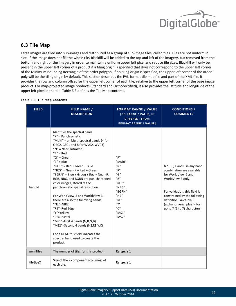
6.3 Tile Map Large images are tiled into sub-images and distributed as a group of sub-image files, called tiles. Tiles are not uniform in size. If the image does not fill the whole tile, blackfill will be added to the top and left of the imagery, but removed from the bottom and right of the imagery in order to maintain a uniform upper left pixel and reduce tile sizes. Blackfill will only be present in the upper left corner of a product if a tiling origin is specified that does not correspond to the upper left corner of the Minimum Bounding Rectangle of the order polygon. If no tiling origin is specified, the upper left corner of the order poly will be the tiling origin by default. This section describes the PVL-format tile map file and part of the XML file. It provides the row and column offset for the upper left corner of each tile, relative to the upper left corner of the base image product. For map-projected image products (Standard and Orthorectified), it also provides the latitude and longitude of the upper left pixel in the tile. Table 6.3 defines the Tile Map contents.
Table 6.3 Tile Map Contents
FIELD FIELD NAME / DESCRIPTION
FORMAT RANGE / VALUE [DG RANGE / VALUE, IF
DIFFERENT FROM FORMAT RANGE / VALUE]
CONDITIONS / COMMENTS
bandId
Identifies the spectral band. “P” = Panchromatic, “Multi” = all Multi-spectral bands (4 for QB02, GE01 and 8 for WV02, WV03) “N” = Near–InfraRed “R” = Red, “G” = Green “B” = Blue "RGB" = Red + Green + Blue “NRG” = Near-IR + Red + Green “BGRN” = Blue + Green + Red + Near-IR RGB, NRG, and BGRN are pan-sharpened color images, stored at the panchromatic spatial resolution. For WorldView-2 and WorldView-3 there are also the following bands: “N2”=NIR2 “RE”=Red Edge “Y”=Yellow “C”=Coastal “MS1”=First 4 bands (N,R,G,B) “MS2”=Second 4 bands (N2,RE,Y,C) For a DEM, this field indicates the spectral band used to create the product.
“P” “Multi” “N” “R” “G” “B” “RGB” “NRG” “BGRN” “N2“ “RE“ “Y“ “C“ “MS1“ “MS2“
N2, RE, Y and C in any band combination are available for WorldView-2 and WorldView-3 only. For validation, this field is constrained by the following definition: A-Za-z0-9 (alphanumeric) plus '-' for up to 7 (1 to 7) characters
numTiles The number of tiles for this product. Range: ≥ 1
tileSizeX Size of the X component (columns) of each tile. Range: ≥ 1

43 DigitalGlobe Imagery Support Data (ISD) Documentation v. 1.1.2 October 2014
FIELD FIELD NAME / DESCRIPTION
FORMAT RANGE / VALUE [DG RANGE / VALUE, IF
DIFFERENT FROM FORMAT RANGE / VALUE]
CONDITIONS / COMMENTS
tileSizeY Size of the Y component (lines) of each tile. Range: ≥ 1
tileUnits Units of tiles
“Pixels” “Meters” “Feet” “Degrees”
Degrees only applicable for DOQQ products.
tileOverlap Overlap of tiles. Range: ≥ 0
The following group is repeated for n = 1,…,numTiles. That is, once for each of the tiles.
BEGIN_GROUP=TILE_n
filename Filename of the tile. Example: “10JUL04165542-P2AS-052380211010_01_P001.NTF”
ULColOffset
Column offset of the upper left pixel of this tile, relative to the upper left pixel of the base image. [This field is calculated as: (columnNum-1)*tileSizeX The columnNum can be found in the filename. For example, “2” in R1C2.]
Range: 0 to ((maxCol-1)*tileSizeX)
ULRowOffset
Row offset of the upper left pixel of this tile, relative to the upper left pixel of the base image. [This field is calculated as: (rowNum-1) * tileSizeY The rowNum can be found in the filename. For example, “1” in R1C2.]
Range: 0 to ((maxRows-1)*tileSizeY)
URColOffset
Column offset of the upper right pixel of this tile, relative to the upper left pixel of the base image. [This field is calculated as: MIN((columnNum*tileSizeX), maximumProductTtileSizeX)-1 The columnNum can be found in the filename. For example, “2” in R1C2.]
Range: – (tileSizeX-1) to (maximumProductTileSizeX-1)
URRowOffset Row offset of the upper right pixel of this tile, relative to the upper left pixel of the base image.
Range: 0 to ((maxRows-1)*tileSizeY)
44 DigitalGlobe Imagery Support Data (ISD) Documentation v. 1.1.2 October 2014
FIELD FIELD NAME / DESCRIPTION
FORMAT RANGE / VALUE [DG RANGE / VALUE, IF
DIFFERENT FROM FORMAT RANGE / VALUE]
CONDITIONS / COMMENTS
[This field is calculated as: (rowNum-1)*tileSizeY The rowNum can be found in the filename. For example, “1” in R1C2.]
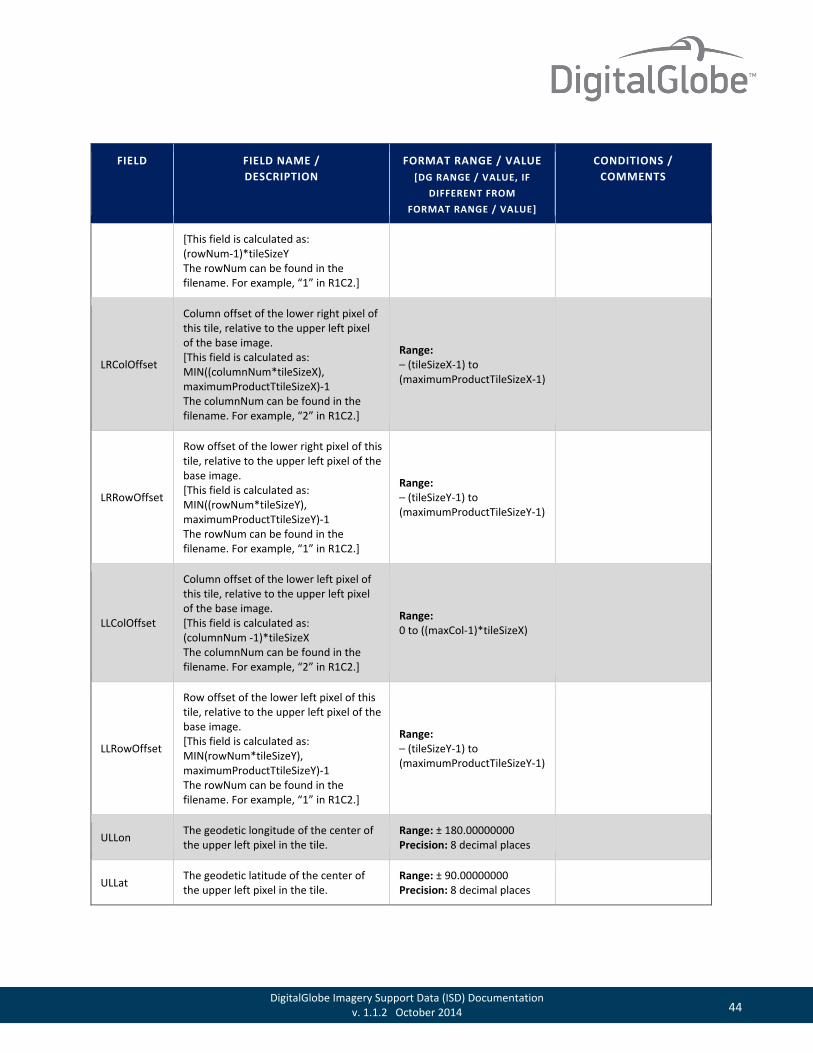
LRColOffset
Column offset of the lower right pixel of this tile, relative to the upper left pixel of the base image. [This field is calculated as: MIN((columnNum*tileSizeX), maximumProductTtileSizeX)-1 The columnNum can be found in the filename. For example, “2” in R1C2.]
Range: – (tileSizeX-1) to (maximumProductTileSizeX-1)
LRRowOffset
Row offset of the lower right pixel of this tile, relative to the upper left pixel of the base image. [This field is calculated as: MIN((rowNum*tileSizeY), maximumProductTtileSizeY)-1 The rowNum can be found in the filename. For example, “1” in R1C2.]
Range: – (tileSizeY-1) to (maximumProductTileSizeY-1)
LLColOffset
Column offset of the lower left pixel of this tile, relative to the upper left pixel of the base image. [This field is calculated as: (columnNum -1)*tileSizeX The columnNum can be found in the filename. For example, “2” in R1C2.]
Range: 0 to ((maxCol-1)*tileSizeX)
LLRowOffset
Row offset of the lower left pixel of this tile, relative to the upper left pixel of the base image. [This field is calculated as: MIN(rowNum*tileSizeY), maximumProductTtileSizeY)-1 The rowNum can be found in the filename. For example, “1” in R1C2.]
Range: – (tileSizeY-1) to (maximumProductTileSizeY-1)
ULLon The geodetic longitude of the center of the upper left pixel in the tile.
Range: ± 180.00000000 Precision: 8 decimal places
ULLat The geodetic latitude of the center of the upper left pixel in the tile.
Range: ± 90.00000000 Precision: 8 decimal places
45 DigitalGlobe Imagery Support Data (ISD) Documentation v. 1.1.2 October 2014
FIELD FIELD NAME / DESCRIPTION
FORMAT RANGE / VALUE [DG RANGE / VALUE, IF
DIFFERENT FROM FORMAT RANGE / VALUE]
CONDITIONS / COMMENTS
URLon The geodetic longitude of the center of the upper right pixel in the tile.
Range: ± 180.00000000 Precision: 8 decimal places
URLat The geodetic latitude of the center of the upper right pixel in the tile.
Range: ± 90.00000000 Precision: 8 decimal places
LRLon The geodetic longitude of the center of the lower right pixel in the tile.
Range: ± 180.00000000 Precision: 8 decimal places
LRLat The geodetic latitude of the center of the lower right pixel in the tile.
Range: ± 90.00000000 Precision: 8 decimal places
LLLon The geodetic longitude of the center of the lower left pixel in the tile.
Range: ± 180.00000000 Precision: 8 decimal places
LLLat The geodetic latitude of the center of the lower left pixel in the tile, in degrees.
Range: ± 90.00000000 Precision: 8 decimal places
ULX
Easting of the center of the upper left pixel of the tile in the specified map projection, datum, and units of the product.
Value: Precision: 8 decimal places
ULY
Northing of the center of the upper left pixel of the tile in the specified map projection, datum, and units of the product.
Precision: 8 decimal places
URX
Easting of the center of the upper right pixel of the tile in the specified map projection, datum, and units of the product.
Precision: 8 decimal places
URY
Northing of the center of the upper right pixel of the tile in the specified map projection, datum, and units of the product.
Precision: 8 decimal places
LRX
Easting of the center of the lower right pixel of the tile in the specified map projection, datum, and units of the product.
Precision: 8 decimal places
LRY Northing of the center of the lower right pixel of the tile in the specified map Precision: 8 decimal places

46 DigitalGlobe Imagery Support Data (ISD) Documentation v. 1.1.2 October 2014
FIELD FIELD NAME / DESCRIPTION
FORMAT RANGE / VALUE [DG RANGE / VALUE, IF
DIFFERENT FROM FORMAT RANGE / VALUE]
CONDITIONS / COMMENTS
projection, datum, and units of the product.
LLX
Easting of the center of the lower left pixel of the tile in the specified map projection, datum, and units of the product.
Precision: 8 decimal places
LLY
Northing of the center of the lower left pixel of the tile in the specified map projection, datum, and units of the product.
Precision: 8 decimal places
END_GROUP=TILE_n
END;
6.4 Rational Polynomial Coefficients This section describes the content of the PVL-format RPC00B file and the corresponding part of the XML file. It contains the coefficients for Rapid Positioning Capability, also called Rational Polynomial Coefficients (RPC). This is a mathematical mapping from object space coordinates to image space coordinates. This mapping includes non-ideal imaging effects, such as lens distortion, light aberration, and atmospheric refraction.
RPC00Bs express the normalized column and row values in an image, (cn, rn), as a ratio of polynomials of the normalized geodetic latitude, longitude, and height, (P, L, H). Normalized values are used instead of actual values in order to minimize numerical errors in the calculation. The scales and offset of each parameter are selected so that all normalized values fall in the range [-1, 1]. The normalization used is as follows: • P = (Latitude - LAT_OFF) / LAT_SCALE • L = (Longitude - LONG_OFF) / LONG_SCALE • H = (Height - HEIGHT_OFF) / HEIGHT_SCALE • rn = (ROW - LINE_OFF) / LINE_SCALE • cn = (Column - SAMP_OFF) / SAMP_SCALE
Each polynomial is up to third order in (P, L, H), having as many as 20 terms. The rational functions are:
LINE_NUM_COEF, LINE_DEN_COEF, SAMP_NUM_COEF, and SAMP_DEN_COEF are 20-term vectors of coefficients that are given in the RPC00B file. p(P,L,H) is a 20-term vector with the following terms:
∑
∑
∑
∑
=
=
=
=
•
•
=
•
•
=20
1
20
120
1
20
1
),,(__
),,(__
),,(__
),,(__
iii
iii
n
iii
iii
n
HLPpCOEFDENSAMP
HLPpCOEFNUMSAMPcand
HLPpCOEFDENLINE
HLPpCOEFNUMLINEr
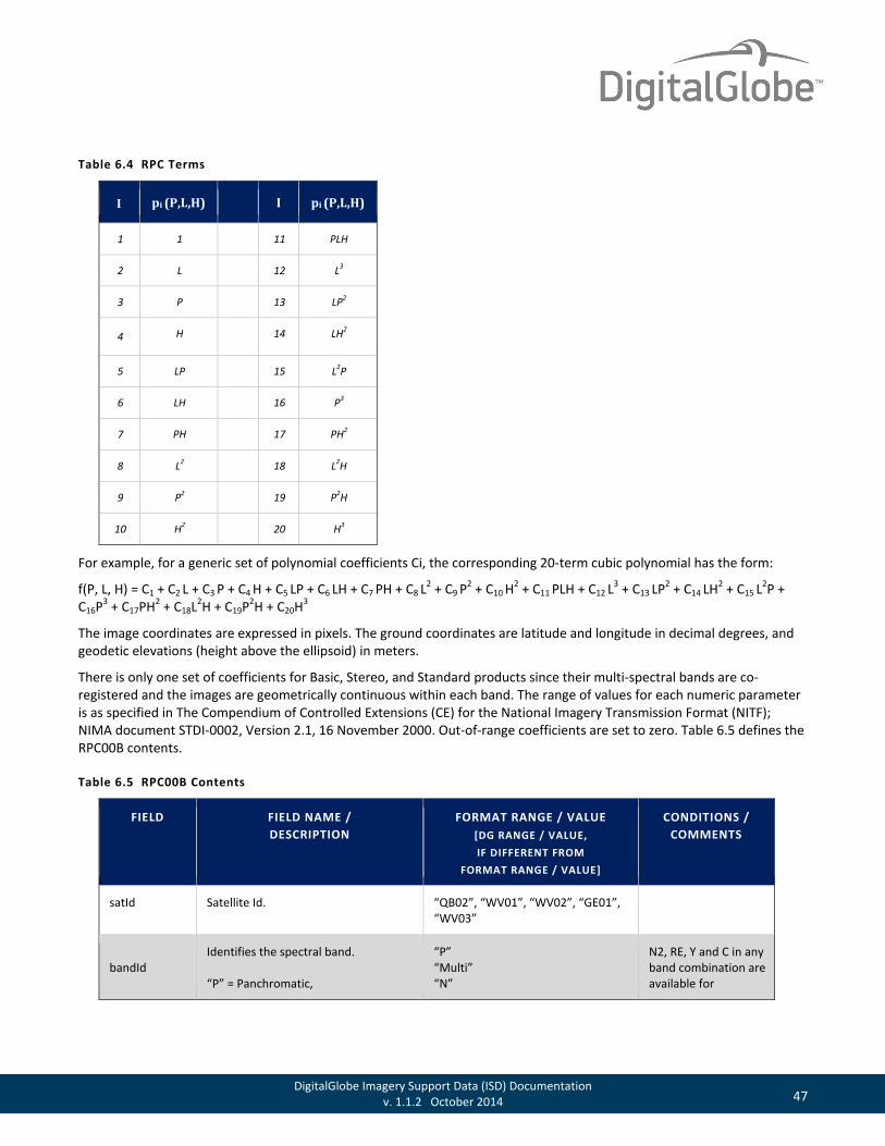
47 DigitalGlobe Imagery Support Data (ISD) Documentation v. 1.1.2 October 2014
Table 6.4 RPC Terms
I pi (P,L,H) I pi (P,L,H)
1 1 11 PLH
2 L 12 L3
3 P 13 LP2
4 H 14 LH2
5 LP 15 L2P
6 LH 16 P3
7 PH 17 PH2
8 L2 18 L2H
9 P2 19 P2H
10 H2 20 H3
For example, for a generic set of polynomial coefficients Ci, the corresponding 20-term cubic polynomial has the form:
f(P, L, H) = C1 + C2 L + C3 P + C4 H + C5 LP + C6 LH + C7 PH + C8 L2 + C9 P
2 + C10 H2 + C11 PLH + C12 L
3 + C13 LP2 + C14 LH2 + C15 L2P +
C16P3 + C17PH2 + C18L2H + C19P2H + C20H3
The image coordinates are expressed in pixels. The ground coordinates are latitude and longitude in decimal degrees, and geodetic elevations (height above the ellipsoid) in meters.
There is only one set of coefficients for Basic, Stereo, and Standard products since their multi-spectral bands are co-registered and the images are geometrically continuous within each band. The range of values for each numeric parameter is as specified in The Compendium of Controlled Extensions (CE) for the National Imagery Transmission Format (NITF); NIMA document STDI-0002, Version 2.1, 16 November 2000. Out-of-range coefficients are set to zero. Table 6.5 defines the RPC00B contents.
Table 6.5 RPC00B Contents
FIELD FIELD NAME / DESCRIPTION
FORMAT RANGE / VALUE [DG RANGE / VALUE, IF DIFFERENT FROM
FORMAT RANGE / VALUE]
CONDITIONS / COMMENTS
satId Satellite Id. “QB02”, “WV01”, “WV02”, “GE01”, “WV03”
bandId Identifies the spectral band. “P” = Panchromatic,
“P” “Multi” “N”
N2, RE, Y and C in any band combination are available for

48 DigitalGlobe Imagery Support Data (ISD) Documentation v. 1.1.2 October 2014
FIELD FIELD NAME / DESCRIPTION
FORMAT RANGE / VALUE [DG RANGE / VALUE, IF DIFFERENT FROM
FORMAT RANGE / VALUE]
CONDITIONS / COMMENTS
“Multi” = all Multi-spectral bands (4 for QB02, GE01 and 8 for WV02, WV03), “N” = Near–InfraRed, “R” = Red, “G” = Green, “B” = Blue, "RGB" = Red + Green + Blue, "NRG" = Near-IR + Red + Green, “BGRN” = Blue + Green + Red + Near-IR. RGB, NRG, and BGRN are pan-sharpened color images, stored at the panchromatic spatial resolution. For WorldView-2 and WorldView-3 there are also the following bands, “N2”=NIR2, “RE”=Red Edge, “Y”=Yellow, “C”=Coastal “MS1” “MS2” For a DEM, this field indicates the spectral band used to create the product.
“R” “G” “B” “RGB” “NRG” “BGRN” “N2” “RE” “Y” “C” “MS1” “MS2”
WorldView-2 and WorldView-3 only.
SpecId
Identification of the specification which defines the RPC implementation used for generating and/or interpreting the coefficients
“RPC00B”
BEGIN_GROUP = IMAGE
Standard (level 2A) and Orthorectified (level 3) products only.
errBias Bias error. 68% non time-varying error estimate for correlated images.
Range: 0.00 – 9999.99 Precision: 2 decimal places
errRand Random error. 68% time-varying error estimate for correlated images.
Range: 0.00 – 9999.99 Precision: 2 decimal places
lineOffset LINE_OFFSET. Range: 0 – 999999
sampOffset SAMP_OFFSET. Range: -9999 to 99999
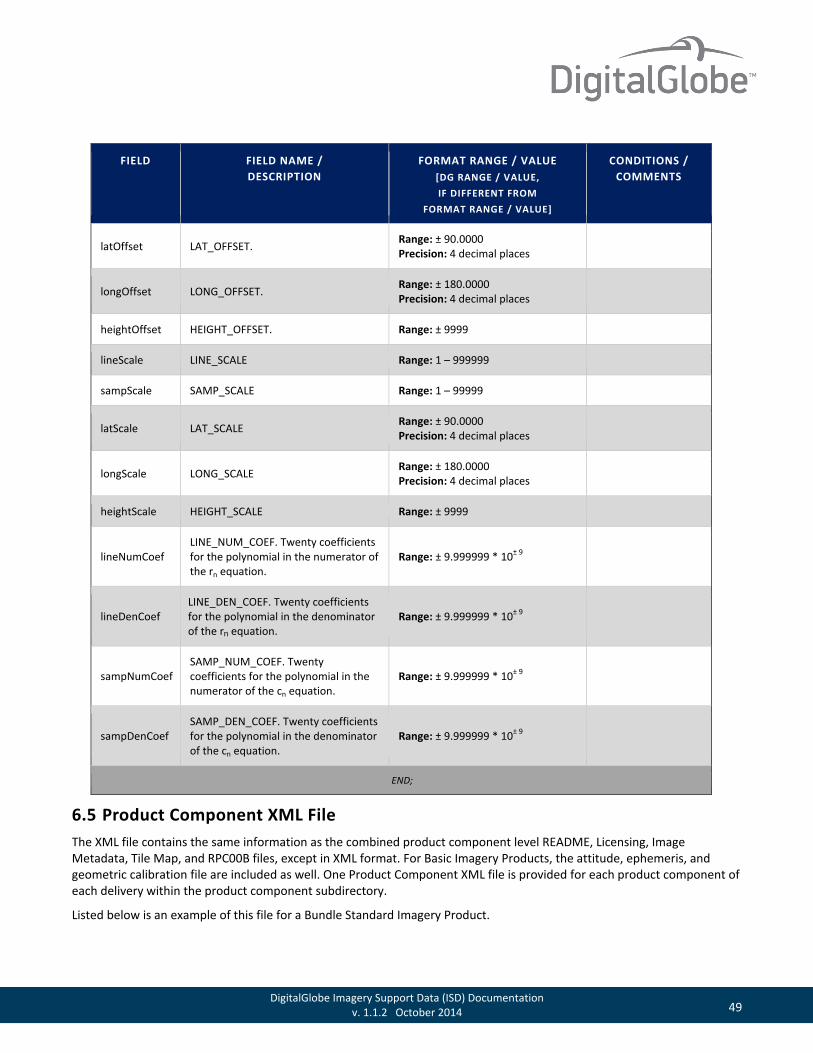
49 DigitalGlobe Imagery Support Data (ISD) Documentation v. 1.1.2 October 2014
FIELD FIELD NAME / DESCRIPTION
FORMAT RANGE / VALUE [DG RANGE / VALUE, IF DIFFERENT FROM
FORMAT RANGE / VALUE]
CONDITIONS / COMMENTS
latOffset LAT_OFFSET. Range: ± 90.0000 Precision: 4 decimal places
longOffset LONG_OFFSET. Range: ± 180.0000 Precision: 4 decimal places
heightOffset HEIGHT_OFFSET. Range: ± 9999
lineScale LINE_SCALE Range: 1 – 999999
sampScale SAMP_SCALE Range: 1 – 99999
latScale LAT_SCALE Range: ± 90.0000 Precision: 4 decimal places
longScale LONG_SCALE Range: ± 180.0000 Precision: 4 decimal places
heightScale HEIGHT_SCALE Range: ± 9999
lineNumCoef LINE_NUM_COEF. Twenty coefficients for the polynomial in the numerator of the rn equation.
Range: ± 9.999999 * 10± 9
lineDenCoef LINE_DEN_COEF. Twenty coefficients for the polynomial in the denominator of the rn equation.
Range: ± 9.999999 * 10± 9
sampNumCoef SAMP_NUM_COEF. Twenty coefficients for the polynomial in the numerator of the cn equation.
Range: ± 9.999999 * 10± 9
sampDenCoef SAMP_DEN_COEF. Twenty coefficients for the polynomial in the denominator of the cn equation.
Range: ± 9.999999 * 10± 9
END;
6.5 Product Component XML File The XML file contains the same information as the combined product component level README, Licensing, Image Metadata, Tile Map, and RPC00B files, except in XML format. For Basic Imagery Products, the attitude, ephemeris, and geometric calibration file are included as well. One Product Component XML file is provided for each product component of each delivery within the product component subdirectory.
Listed below is an example of this file for a Bundle Standard Imagery Product.
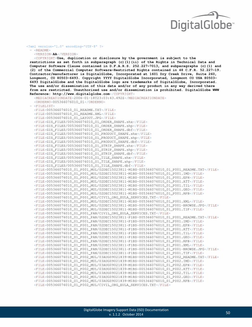
50 DigitalGlobe Imagery Support Data (ISD) Documentation v. 1.1.2 October 2014
<?xml version="1.0" encoding="UTF-8" ?> - <README> <VERSION>AA</VERSION> <COPYRIGHT>Use, duplication or disclosure by the government is subject to the restrictions as set forth in subparagraph (c)(1)(ii) of the Rights in Technical Data and Computer Software Clause contained in D.F.A.R.S. 252.227-7013, and subparagraphs (c)(1) and (2) of the Commercial Computer Software-Restricted Rights contained in 48 C.F.R. 52.227-19. Contractor/manufacturer is DigitalGlobe, Incorporated at 1601 Dry Creek Drive, Suite 260, Longmont, CO 80503-6493. Copyright YYYY DigitalGlobe Incorporated, Longmont CO USA 80503-6493 DigitalGlobe and the DigitalGlobe logo are trademarks of DigitalGlobe, Incorporated. The use and/or dissemination of this data and/or of any product in any way derived there from are restricted. Unauthorized use and/or dissemination is prohibited. DigitalGlobe WWW Reference: http://www.digitalglobe.com</COPYRIGHT> <MEDIACREATIONDATE>2006-01-18T23:03:43.492Z</MEDIACREATIONDATE> <ORDERNO>005366076010_01</ORDERNO> - <FILELIST> <FILE>005366076010_01_README.TXT</FILE> <FILE>005366076010_01_README.XML</FILE> <FILE>005366076010_01_LAYOUT.JPG</FILE> <FILE>GIS_FILES/005366076010_01_ORDER_SHAPE.shx</FILE> <FILE>GIS_FILES/005366076010_01_ORDER_SHAPE.shp</FILE> <FILE>GIS_FILES/005366076010_01_ORDER_SHAPE.dbf</FILE> <FILE>GIS_FILES/005366076010_01_PRODUCT_SHAPE.shx</FILE> <FILE>GIS_FILES/005366076010_01_PRODUCT_SHAPE.shp</FILE> <FILE>GIS_FILES/005366076010_01_PRODUCT_SHAPE.dbf</FILE> <FILE>GIS_FILES/005366076010_01_STRIP_SHAPE.shx</FILE> <FILE>GIS_FILES/005366076010_01_STRIP_SHAPE.shp</FILE> <FILE>GIS_FILES/005366076010_01_STRIP_SHAPE.dbf</FILE> <FILE>GIS_FILES/005366076010_01_TILE_SHAPE.shx</FILE> <FILE>GIS_FILES/005366076010_01_TILE_SHAPE.shp</FILE> <FILE>GIS_FILES/005366076010_01_TILE_SHAPE.dbf</FILE> <FILE>005366076010_01_P001_MUL/02DEC15023811-M1BS-005366076010_01_P001_README.TXT</FILE> <FILE>005366076010_01_P001_MUL/02DEC15023811-M1BS-005366076010_01_P001.IMD</FILE> <FILE>005366076010_01_P001_MUL/02DEC15023811-M1BS-005366076010_01_P001.EPH</FILE> <FILE>005366076010_01_P001_MUL/02DEC15023811-M1BS-005366076010_01_P001.ATT</FILE> <FILE>005366076010_01_P001_MUL/02DEC15023811-M1BS-005366076010_01_P001.TIL</FILE> <FILE>005366076010_01_P001_MUL/02DEC15023811-M1BS-005366076010_01_P001.GEO</FILE> <FILE>005366076010_01_P001_MUL/02DEC15023811-M1BS-005366076010_01_P001.RPB</FILE> <FILE>005366076010_01_P001_MUL/CIVIL_ORG_EULA_SERVICES.TXT</FILE> <FILE>005366076010_01_P001_MUL/02DEC15023811-M1BS-005366076010_01_P001.XML</FILE> <FILE>005366076010_01_P001_MUL/02DEC15023811-M1BS-005366076010_01_P001-BROWSE.JPG</FILE> <FILE>005366076010_01_P001_MUL/02DEC15023811-M1BS-005366076010_01_P001.TIF</FILE> <FILE>005366076010_01_P001_PAN/CIVIL_ORG_EULA_SERVICES.TXT</FILE> <FILE>005366076010_01_P001_PAN/02DEC15023811-P1BS-005366076010_01_P001_README.TXT</FILE> <FILE>005366076010_01_P001_PAN/02DEC15023811-P1BS-005366076010_01_P001.IMD</FILE> <FILE>005366076010_01_P001_PAN/02DEC15023811-P1BS-005366076010_01_P001.EPH</FILE> <FILE>005366076010_01_P001_PAN/02DEC15023811-P1BS-005366076010_01_P001.ATT</FILE> <FILE>005366076010_01_P001_PAN/02DEC15023811-P1BS-005366076010_01_P001.TIL</FILE> <FILE>005366076010_01_P001_PAN/02DEC15023811-P1BS-005366076010_01_P001.GEO</FILE> <FILE>005366076010_01_P001_PAN/02DEC15023811-P1BS-005366076010_01_P001.RPB</FILE> <FILE>005366076010_01_P001_PAN/02DEC15023811-P1BS-005366076010_01_P001.XML</FILE> <FILE>005366076010_01_P001_PAN/02DEC15023811-P1BS-005366076010_01_P001-BROWSE.JPG</FILE> <FILE>005366076010_01_P001_PAN/02DEC15023811-P1BS-005366076010_01_P001.TIF</FILE> <FILE>005366076010_01_P002_MUL/03AUG09021839-M1BS-005366076010_01_P002_README.TXT</FILE> <FILE>005366076010_01_P002_MUL/03AUG09021839-M1BS-005366076010_01_P002.IMD</FILE> <FILE>005366076010_01_P002_MUL/03AUG09021839-M1BS-005366076010_01_P002.EPH</FILE> <FILE>005366076010_01_P002_MUL/03AUG09021839-M1BS-005366076010_01_P002.ATT</FILE> <FILE>005366076010_01_P002_MUL/03AUG09021839-M1BS-005366076010_01_P002.TIL</FILE> <FILE>005366076010_01_P002_MUL/03AUG09021839-M1BS-005366076010_01_P002.GEO</FILE> <FILE>005366076010_01_P002_MUL/03AUG09021839-M1BS-005366076010_01_P002.RPB</FILE> <FILE>005366076010_01_P002_MUL/CIVIL_ORG_EULA_SERVICES.TXT</FILE>

51 DigitalGlobe Imagery Support Data (ISD) Documentation v. 1.1.2 October 2014
<FILE>005366076010_01_P002_MUL/03AUG09021839-M1BS-005366076010_01_P002.XML</FILE> <FILE>005366076010_01_P002_MUL/03AUG09021839-M1BS-005366076010_01_P002-BROWSE.JPG</FILE> <FILE>005366076010_01_P002_MUL/03AUG09021839-M1BS-005366076010_01_P002.TIF</FILE> <FILE>005366076010_01_P002_PAN/CIVIL_ORG_EULA_SERVICES.TXT</FILE> <FILE>005366076010_01_P002_PAN/03AUG09021839-P1BS-005366076010_01_P002_README.TXT</FILE> <FILE>005366076010_01_P002_PAN/03AUG09021839-P1BS-005366076010_01_P002.IMD</FILE> <FILE>005366076010_01_P002_PAN/03AUG09021839-P1BS-005366076010_01_P002.EPH</FILE> <FILE>005366076010_01_P002_PAN/03AUG09021839-P1BS-005366076010_01_P002.ATT</FILE> <FILE>005366076010_01_P002_PAN/03AUG09021839-P1BS-005366076010_01_P002.TIL</FILE> <FILE>005366076010_01_P002_PAN/03AUG09021839-P1BS-005366076010_01_P002.GEO</FILE> <FILE>005366076010_01_P002_PAN/03AUG09021839-P1BS-005366076010_01_P002.RPB</FILE> <FILE>005366076010_01_P002_PAN/03AUG09021839-P1BS-005366076010_01_P002.XML</FILE> <FILE>005366076010_01_P002_PAN/03AUG09021839-P1BS-005366076010_01_P002-BROWSE.JPG</FILE> <FILE>005366076010_01_P002_PAN/03AUG09021839-P1BS-005366076010_01_P002.TIF</FILE> </FILELIST> <AREADESCRIPTION>PS_WV_02</AREADESCRIPTION> <DGORDERNO>005366076</DGORDERNO> <DGORDERITEMNO>005366076010</DGORDERITEMNO> <CUSTOMERORDERNO>PS_02 1B+ BA XML Taipei</CUSTOMERORDERNO> <CUSTOMERORDERITEMNO>40009</CUSTOMERORDERITEMNO> <COLLECTIONSTART>2002-12-15T02:38:08.618201Z</COLLECTIONSTAR> <COLLECTIONSTOP>2003-08-09T02:18:48.385340Z</COLLECTIONSTOP> <COUNTRYCODE>TW</COUNTRYCODE> <NUMBEROFLOOKS>1</NUMBEROFLOOKS> <CLOUDCOVER>-999.0</CLOUDCOVER> <NWLAT>25.12000000</NWLAT> <NWLONG>121.60000000</NWLONG> <SELAT>25.04000000</SELAT> <SELONG>121.73000000</SELONG> </README>
6.6 Manifest File The manifest file outlines the directory structure for products delivered by FTP. Below is an example of the manifest file delivered for a Standard Pansharpened Imagery product.
./005510916010_01.MAN
./005510916010_01
./005510916010_01/005510916010_01_README.TXT
./005510916010_01/005510916010_01_README.XML
./005510916010_01/005510916010_01_LAYOUT.JPG
./005510916010_01/GIS_FILES
./005510916010_01/GIS_FILES/005510916010_01_ORDER_SHAPE.shx
./005510916010_01/GIS_FILES/005510916010_01_ORDER_SHAPE.shp
./005510916010_01/GIS_FILES/005510916010_01_ORDER_SHAPE.dbf
./005510916010_01/GIS_FILES/005510916010_01_PRODUCT_SHAPE.shx
./005510916010_01/GIS_FILES/005510916010_01_PRODUCT_SHAPE.shp
./005510916010_01/GIS_FILES/005510916010_01_PRODUCT_SHAPE.dbf
./005510916010_01/GIS_FILES/005510916010_01_STRIP_SHAPE.shx
./005510916010_01/GIS_FILES/005510916010_01_STRIP_SHAPE.shp
./005510916010_01/GIS_FILES/005510916010_01_STRIP_SHAPE.dbf
./005510916010_01/GIS_FILES/005510916010_01_TILE_SHAPE.shx
./005510916010_01/GIS_FILES/005510916010_01_TILE_SHAPE.shp
./005510916010_01/GIS_FILES/005510916010_01_TILE_SHAPE.dbf
./005510916010_01/005510916010_01_P001_PSH
./005510916010_01/005510916010_01_P001_PSH/03MAR13174755-S2AS-005510916010_01_P001_README.TXT ./005510916010_01/005510916010_01_P001_PSH/03MAR13174755-S2AS-005510916010_01_P001.IMD ./005510916010_01/005510916010_01_P001_PSH/03MAR13174755-S2AS-005510916010_01_P001.TIL ./005510916010_01/005510916010_01_P001_PSH/03MAR13174755-S2AS-005510916010_01_P001.RPB ./005510916010_01/005510916010_01_P001_PSH/COMMERCIAL.TXT ./005510916010_01/005510916010_01_P001_PSH/03MAR13174755-S2AS-005510916010_01_P001.XML

52 DigitalGlobe Imagery Support Data (ISD) Documentation v. 1.1.2 October 2014
./005510916010_01/005510916010_01_P001_PSH/03MAR13174755-S2AS-005510916010_01_P001-BROWSE.JPG ./005510916010_01/005510916010_01_P001_PSH/03MAR13174755-S2AS_R1C1-005510916010_01_P001.TIF ./005510916010_01/005510916010_01_P001_PSH/03MAR13174755-S2AS_R1C2-005510916010_01_P001.TIF ./005510916010_01/005510916010_01_P001_PSH/03MAR13174755-S2AS_R1C3-005510916010_01_P001.TIF ./005510916010_01/005510916010_01_P001_PSH/03MAR13174755-S2AS_R2C1-005510916010_01_P001.TIF ./005510916010_01/005510916010_01_P001_PSH/03MAR13174755-S2AS_R2C3-005510916010_01_P001.TIF ./005510916010_01/005510916010_01_P001_PSH/03MAR13174755-S2AS_R3C2-005510916010_01_P001.TIF ./005510916010_01/005510916010_01_P001_PSH/03MAR13174755-S2AS_R4C1-005510916010_01_P001.TIF ./005510916010_01/005510916010_01_P001_PSH/03MAR13174755-S2AS_R4C3-005510916010_01_P001.TIF ./005510916010_01/005510916010_01_P001_PSH/03MAR13174755-S2AS_R4C2-005510916010_01_P001.TIF ./005510916010_01/005510916010_01_P001_PSH/03MAR13174755-S2AS_R3C3-005510916010_01_P001.TIF ./005510916010_01/005510916010_01_P001_PSH/03MAR13174755-S2AS_R3C1-005510916010_01_P001.TIF ./005510916010_01/005510916010_01_P001_PSH/03MAR13174755-S2AS_R2C2-005510916010_01_P001.TIF
6.7 Stereo File This file is provided only for Stereo Pair Imagery products, and describes information about individual stereo models. The stereo file contains three angular measures of convergent stereo imaging geometry: the convergence angle, the asymmetry angle, and the bisector elevation angle (BIE). These measure the geometrical relationship between two rays that intersect at a common ground point, one from the fore image and one from the aft image. These intersecting rays define a plane, called the convergence plane. The convergence angle is the angle between the two rays in the convergence plane. The asymmetry angle is the angle between the ray bisector (also in the convergence plane), and the projection of a vertical from the ground point onto the convergence plane. The BIE is the elevation of the bisector. That is, the angle from the horizontal plane containing the ground point to the bisector. Each angle is computed at a ground target point near the beginning of the stereo overlap, and at another point near the end of the stereo overlap. Table 6.6 defines the Stereo File contents.
Figure 6.2 Stereo Geometry Angles
Stereo geometry is often described in terms of convergence angle and asymmetry angle at a ground point defined by radius vector, as illustrated in Figure 6.2. These angles are measured in the plane formed by the two lines of sight (one for each image) to the ground point.

53 DigitalGlobe Imagery Support Data (ISD) Documentation v. 1.1.2 October 2014
Table 6.6 Stereo File Contents
FIELD FIELD NAME / DESCRIPTION
FORMAT RANGE / VALUE [DG RANGE / VALUE, IF DIFFERENT FROM
FORMAT RANGE / VALUE]
CONDITIONS / COMMENTS
numPair Number of stereo pairs in this file. 1
The following group is repeated for n = 1,…,numPair (for all stereo pairs).
BEGIN_GROUP=STEREO_PAIR_n
firstId Image file name of the first image (image acquired at the earlier time) of a stereo pair.
For products produced by DigitalGlobe, this name will follow the standard product naming conventions.
secondId Image file name of the second image of the stereo pair. See firstID.
overlap Fractional overlap: overlap area, measured on the ground, divided by the ground area of the second image.
0.00 to 1.00
ULLat Geodetic latitude of the upper left corner of the minimum-bounding rectangle that covers the stereo model.
Range: ± 90.000000 Precision: Six decimal places
ULLon Geodetic longitude of the upper left corner of the minimum-bounding rectangle that covers the stereo model.
Range: ± 180.000000 Precision: Six decimal places
LRLat Geodetic latitude of the lower right corner of the minimum-bounding rectangle that covers the stereo model.
Range: ± 90.000000 Precision: Six decimal places
LRLon Geodetic longitude of the lower right corner of the minimum-bounding rectangle that covers the stereo model.
Range: ± 180.000000 Precision: Six decimal places
B_Conv Beginning convergence angle. This is measured at the first lines of the stereo overlap.
Range: 0.00 to 180.00 Precision: Two decimal places
E_Conv Ending convergence angle. This is measured at the last lines of the stereo overlap.
Range: 0.00 to 180.00 Precision: Two decimal places
B_Asym Beginning asymmetry angle. This is measured at the first lines of the stereo overlap.
Range: 0.00 to 90.00 Precision: Two decimal places

54 DigitalGlobe Imagery Support Data (ISD) Documentation v. 1.1.2 October 2014
FIELD FIELD NAME / DESCRIPTION
FORMAT RANGE / VALUE [DG RANGE / VALUE, IF DIFFERENT FROM
FORMAT RANGE / VALUE]
CONDITIONS / COMMENTS
E_Asym Ending asymmetry angle. This is measured at the last lines of the stereo overlap.
Range: 0.00 to 90.00 Precision: Two decimal places
B_BIE Beginning BIE less convergence angle of stereo mate. This is measured at the first lines of the stereo overlap.
Range: -90.00 to 90.00 Precision: Two decimal places
E_BIE Ending BIE less convergence angle of stereo mate. This is measured at the last lines of the stereo overlap.
Range: -90.00 to 90.00 Precision: Two decimal places
END_GROUP=STEREO_PAIR_n
END;

55 DigitalGlobe Imagery Support Data (ISD) Documentation v. 1.1.2 October 2014
Appendix A: Example PVL Format
The following is an example PVL format. It is for illustration purposes only. version = "21.0"; /* ISD Version */ generationTime = 2003-12-18T17:54:28.000000Z; productOrderId = "T-111-C"; productCatalogId = “2030011234567801”; imageDescriptor = "Standard2A"; bandId = "P"; panSharpenAlgorithm = "None"; numRows = 22472; numColumns = 14384; productLevel = "LV2A"; productType = “Standard“; numberOfLooks = 1; radiometricLevel = "Corrected"; radiometricEnhancement = "Off"; bitsPerPixel = 8; compressionType = "None"; BEGIN_GROUP = BAND_P ULLon = -158.26477950; ULLat = 21.59936003; ULHAE = 0.00; URLon = -158.13533250; URLat = 21.59936003; URHAE = 0.00; LRLon = -158.13533250; LRLat = 21.39712529; LRHAE = 0.00; LLLon = -158.26477950; LLLat = 21.39712527; LLHAE = 0.00; absCalFactor = 4.734886e-01; effectiveBandwidth = 3.9800e-01; END_GROUP = BAND_P outputFormat = "GeoTIFF"; BEGIN_GROUP = IMAGE_1 satId = "QB02"; mode = “FullSwath“; CatId = "101001000173E700"; minCollectedRowGSD = 0.618; maxCollectedRowGSD = 0.621; meanCollectedRowGSD = 0.619; minCollectedColGSD = 0.629; maxCollectedColGSD = 0.630; meanCollectedColGSD = 0.629; meanCollectedGSD = 0.624; rowUncertainty = 166.70; colUncertainty = 292.81; minSunAz = 155.3; maxSunAz = 156.8; meanSunAz = 155.8; minSunEl = 43.2; maxSunEl = 44.2; meanSunEl = 43.7; minSatAz = 119.7; maxSatAz = 119.9; meanSatAz = 119.8; minSatEl = 80.0; maxSatEl = 82.0; meanSatEl = 81.1; minInTrackViewAngle = -3.4;

56 DigitalGlobe Imagery Support Data (ISD) Documentation v. 1.1.2 October 2014
maxInTrackViewAngle = -1.4; meanInTrackViewAngle = -2.4; minCrossTrackViewAngle = 8.6; maxCrossTrackViewAngle = 15.6; meanCrossTrackViewAngle = 11.8; minOffNadirViewAngle = 9.2; maxOffNadirViewAngle = 17.2; meanOffNadirViewAngle = 12.2; PNIIRS = 3.8; cloudCover = 0.000; imageQuality = "Fair"; TDILevel = 13; positionKnowledgeSrc = "R"; attitudeKnowledgeSrc = "R"; revNumber = 6279; END_GROUP = IMAGE_1 BEGIN_GROUP = MAP_PROJECTED_PRODUCT earliestAcqTime = 2002-11-30T21:06:27.161677Z; latestAcqTime = 2002-11-30T21:06:27.161677Z; datumName = "INTERNATIONAL 1924"; semiMajorAxis = 6378388.0000; inverseFlattening = 297.000000000; datumOffset = ( 0.000, 0.000, 0.000 ); mapProjName = "Geographic (Lat/Long)"; mapProjCode = 17; mapProjParam = ( 6366197.723675813, 0.000000000, 0.000000000, 0.000000000, 0.000000000, 0.000000000, 0.000000000, 0.000000000, 0.000000000, 0.000000000, 0.000000000, 0.000000000, 0.000000000, 0.000000000, 0.000000000 ); productUnits = "DD"; originX = -158.26477950; originY = 21.59992350; orientationAngle = 0.0; colSpacing = 0.00; rowSpacing = 0.00; productGSD = 0.60; edgeMatch = "Off"; colorBalance = "On"; ULX = -158.26477950; ULY = 21.59992350; ULH = 0.00; URX = -158.13533250; URY = 21.59992350; URH = 0.00; LRX = -158.13533250; LRY = 21.39768450; LRH = 0.00; LLX = -158.26477950; LLY = 21.39768450; LLH = 0.00;

57 DigitalGlobe Imagery Support Data (ISD) Documentation v. 1.1.2 October 2014
DEMCorrection = "none"; numGCP = 4; END_GROUP = MAP_PROJECTED_PRODUCT END; /* END OF MODULE */
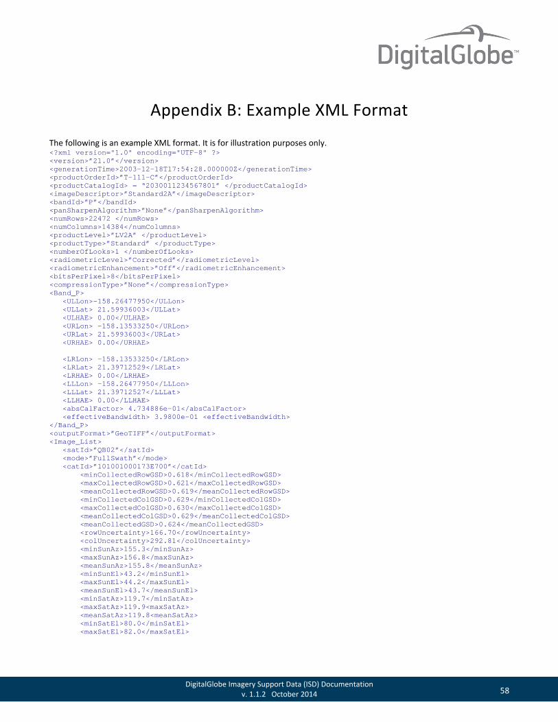
58 DigitalGlobe Imagery Support Data (ISD) Documentation v. 1.1.2 October 2014
Appendix B: Example XML Format
The following is an example XML format. It is for illustration purposes only. <?xml version="1.0" encoding="UTF-8" ?> <version>”21.0”</version> <generationTime>2003-12-18T17:54:28.000000Z</generationTime> <productOrderId>”T-111-C”</productOrderId> <productCatalogId> = “2030011234567801” </productCatalogId> <imageDescriptor>”Standard2A”</imageDescriptor> <bandId>”P”</bandId> <panSharpenAlgorithm>”None”</panSharpenAlgorithm> <numRows>22472 </numRows> <numColumns>14384</numColumns> <productLevel>”LV2A” </productLevel> <productType>”Standard” </productType> <numberOfLooks>1 </numberOfLooks> <radiometricLevel>”Corrected”</radiometricLevel> <radiometricEnhancement>”Off”</radiometricEnhancement> <bitsPerPixel>8</bitsPerPixel> <compressionType>”None”</compressionType> <Band_P> <ULLon>-158.26477950</ULLon> <ULLat> 21.59936003</ULLat> <ULHAE> 0.00</ULHAE> <URLon> -158.13533250</URLon> <URLat> 21.59936003</URLat> <URHAE> 0.00</URHAE> <LRLon> -158.13533250</LRLon> <LRLat> 21.39712529</LRLat> <LRHAE> 0.00</LRHAE> <LLLon> -158.26477950</LLLon> <LLLat> 21.39712527</LLLat> <LLHAE> 0.00</LLHAE> <absCalFactor> 4.734886e-01</absCalFactor> <effectiveBandwidth> 3.9800e-01 <effectiveBandwidth> </Band_P> <outputFormat>”GeoTIFF”</outputFormat> <Image_List> <satId>”QB02”</satId> <mode>”FullSwath”</mode> <catId>”101001000173E700”</catId> <minCollectedRowGSD>0.618</minCollectedRowGSD> <maxCollectedRowGSD>0.621</maxCollectedRowGSD> <meanCollectedRowGSD>0.619</meanCollectedRowGSD> <minCollectedColGSD>0.629</minCollectedColGSD> <maxCollectedColGSD>0.630</maxCollectedColGSD> <meanCollectedColGSD>0.629</meanCollectedColGSD> <meanCollectedGSD>0.624</meanCollectedGSD> <rowUncertainty>166.70</rowUncertainty> <colUncertainty>292.81</colUncertainty> <minSunAz>155.3</minSunAz> <maxSunAz>156.8</maxSunAz> <meanSunAz>155.8</meanSunAz> <minSunEl>43.2</minSunEl> <maxSunEl>44.2</maxSunEl> <meanSunEl>43.7</meanSunEl> <minSatAz>119.7</minSatAz> <maxSatAz>119.9<maxSatAz> <meanSatAz>119.8<meanSatAz> <minSatEl>80.0</minSatEl> <maxSatEl>82.0</maxSatEl>
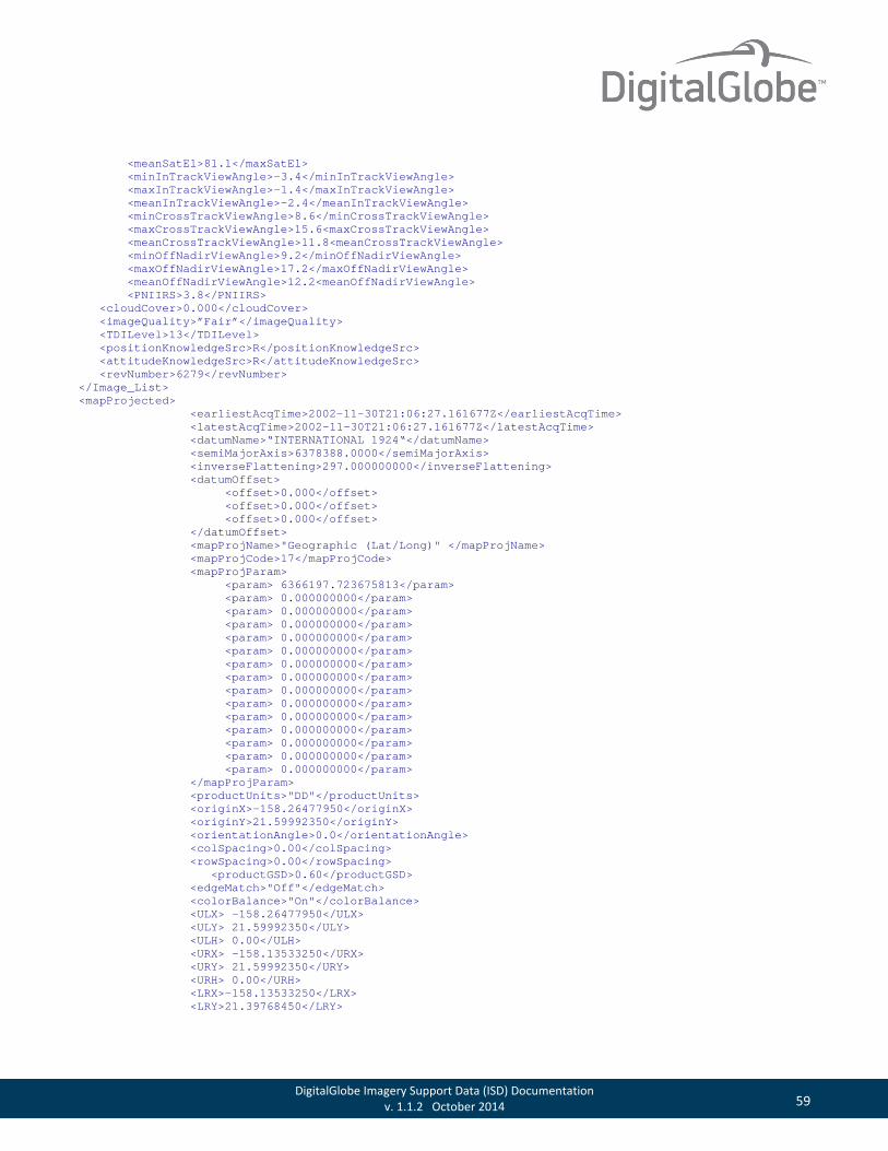
59 DigitalGlobe Imagery Support Data (ISD) Documentation v. 1.1.2 October 2014
<meanSatEl>81.1</maxSatEl> <minInTrackViewAngle>-3.4</minInTrackViewAngle> <maxInTrackViewAngle>-1.4</maxInTrackViewAngle> <meanInTrackViewAngle>-2.4</meanInTrackViewAngle> <minCrossTrackViewAngle>8.6</minCrossTrackViewAngle> <maxCrossTrackViewAngle>15.6<maxCrossTrackViewAngle> <meanCrossTrackViewAngle>11.8<meanCrossTrackViewAngle> <minOffNadirViewAngle>9.2</minOffNadirViewAngle> <maxOffNadirViewAngle>17.2</maxOffNadirViewAngle> <meanOffNadirViewAngle>12.2<meanOffNadirViewAngle> <PNIIRS>3.8</PNIIRS> <cloudCover>0.000</cloudCover> <imageQuality>”Fair”</imageQuality> <TDILevel>13</TDILevel> <positionKnowledgeSrc>R</positionKnowledgeSrc> <attitudeKnowledgeSrc>R</attitudeKnowledgeSrc> <revNumber>6279</revNumber> </Image_List> <mapProjected> <earliestAcqTime>2002-11-30T21:06:27.161677Z</earliestAcqTime> <latestAcqTime>2002-11-30T21:06:27.161677Z</latestAcqTime> <datumName>“INTERNATIONAL 1924“</datumName> <semiMajorAxis>6378388.0000</semiMajorAxis> <inverseFlattening>297.000000000</inverseFlattening> <datumOffset> <offset>0.000</offset> <offset>0.000</offset> <offset>0.000</offset> </datumOffset> <mapProjName>"Geographic (Lat/Long)" </mapProjName> <mapProjCode>17</mapProjCode> <mapProjParam> <param> 6366197.723675813</param> <param> 0.000000000</param> <param> 0.000000000</param> <param> 0.000000000</param> <param> 0.000000000</param> <param> 0.000000000</param> <param> 0.000000000</param> <param> 0.000000000</param> <param> 0.000000000</param> <param> 0.000000000</param> <param> 0.000000000</param> <param> 0.000000000</param> <param> 0.000000000</param> <param> 0.000000000</param> <param> 0.000000000</param> </mapProjParam> <productUnits>"DD"</productUnits> <originX>-158.26477950</originX> <originY>21.59992350</originY> <orientationAngle>0.0</orientationAngle> <colSpacing>0.00</colSpacing> <rowSpacing>0.00</rowSpacing> <productGSD>0.60</productGSD> <edgeMatch>"Off"</edgeMatch> <colorBalance>"On"</colorBalance> <ULX> -158.26477950</ULX> <ULY> 21.59992350</ULY> <ULH> 0.00</ULH> <URX> -158.13533250</URX> <URY> 21.59992350</URY> <URH> 0.00</URH> <LRX>-158.13533250</LRX> <LRY>21.39768450</LRY>

60 DigitalGlobe Imagery Support Data (ISD) Documentation v. 1.1.2 October 2014
<LRH>0.00</LRH> <LLX>-158.26477950</LLX> <LLY>21.39768450</LLY> <LLH> 0.00</LLH> <DEMCorrection>"none"</DEMCorrection> <numGCP>4</numGCP> </mapProjected>
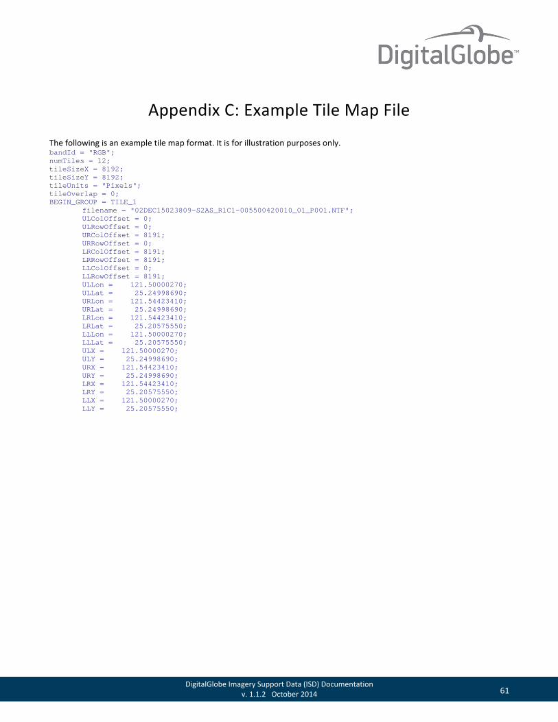
61 DigitalGlobe Imagery Support Data (ISD) Documentation v. 1.1.2 October 2014
Appendix C: Example Tile Map File
The following is an example tile map format. It is for illustration purposes only. bandId = "RGB"; numTiles = 12; tileSizeX = 8192; tileSizeY = 8192; tileUnits = "Pixels"; tileOverlap = 0; BEGIN_GROUP = TILE_1 filename = "02DEC15023809-S2AS_R1C1-005500420010_01_P001.NTF"; ULColOffset = 0; ULRowOffset = 0; URColOffset = 8191; URRowOffset = 0; LRColOffset = 8191; LRRowOffset = 8191; LLColOffset = 0; LLRowOffset = 8191; ULLon = 121.50000270; ULLat = 25.24998690; URLon = 121.54423410; URLat = 25.24998690; LRLon = 121.54423410; LRLat = 25.20575550; LLLon = 121.50000270; LLLat = 25.20575550; ULX = 121.50000270; ULY = 25.24998690; URX = 121.54423410; URY = 25.24998690; LRX = 121.54423410; LRY = 25.20575550; LLX = 121.50000270; LLY = 25.20575550;

62 DigitalGlobe Imagery Support Data (ISD) Documentation v. 1.1.2 October 2014
Glossary
AOI
Area of Interest. The area on the Earth that you want to view.
Bilinear Interpolation
Bilinear interpolation uses the value of the four nearest cell centers to determine the value on the output raster. The new value is a weighted average of these four values, adjusted to account for their distance from the center of the output cell. The result is a smoother-looking surface than provided by “nearest neighbor”.
Bicubic Interpolation
Bicubic interpolation combines data points on a two-dimensional grid. This method outputs the smoothest surface of all interpolation methods.
CE
Circular Error.
CE90
Circular Error at 90% confidence. Indicates that the actual location of an object is represented on the image within the stated accuracy for 90% of the points.
CIR
Color Infrared.
COTS
Commercial-Off-The-Shelf.
DEM
See Digital Elevation Model.
Digital Elevation Model (DEM)
A digital model of terrain relief, usually derived from stereo imagery. A DEM is used to remove terrain distortions from Orthorectified Imagery products.
DRA
Dynamic Range Adjustment. An optional post-processing feature that enhances the visual interpretability of the image.
DTED
Digital Terrain Elevation Data.
ECF
Earth Centered Fixed.
FTP
File Transfer Protocol.
GCP
See Ground Control Point.

63 DigitalGlobe Imagery Support Data (ISD) Documentation v. 1.1.2 October 2014
GE01
GeoEye-1 Satellite.
Geographic Projection
Maps longitudes as straight vertical lines and latitudes as straight horizontal lines all spaced out consistently for constant intervals.
GeoTIFF format
Georeferenced tagged image file format. A GeoTIFF file is a TIFF file that is embedded with geographic data tags.
Ground Control Point (GCP)
A known geographic coordinate location on the ground. A GCP can be collected from ground survey or maps (Primary GCP), or derived via triangulation of primary GCPs (Secondary GCP). GCPs can be planimetric (x, y; latitude, longitude) or vertical (x, y, z; latitude, longitude, elevation).
Ground Sample Distance (GSD)
The size of a single pixel as measured on the ground. This is also referred to as “resolution”.
GSD
See Ground Sample Distance.
Image Support Data (ISD)
A set of files which contain all the necessary data necessary to use and process Imagery Products. These files can be viewed as a collection point for all ancillary data that is expected to be useful to a customer.
ISD
See Image Support Data.
JPEG2000 format
The JPEG2000 format is a JPEG format that was introduced in the year 2000. It has considerable advantages over basic JPEG format including error resilience and progressive transmission.
LE
Linear Error.
LE90
Linear Error at 90 percent confidence. Indicates that the actual elevation of an object is represented within the stated accuracy for at least 90% of elevation posts.
MBR
Minimum-bounding rectangle.
Metadata
Ancillary data that describes and defines the imagery product. DigitalGlobe provides metadata in a set of Image Support Data files.
Mosaic
The process of digitally assembling images to create contiguous large-area coverage.
64 DigitalGlobe Imagery Support Data (ISD) Documentation v. 1.1.2 October 2014
MrSid format
Multi-Resolution Seamless Image Database. This format compresses large raster images while maintaining the image quality.
MS
See Multispectral.
Multispectral
Imagery with data recorded in multiple discrete spectral bands. Imagery collected in four or eight ranges of wavelengths in the electromagnetic spectrum.
Nadir
The point on the ground vertically beneath the sensor.
National Imagery Transmission Format
See NITF format.
Nearest Neighbor Interpolation
Uses the value of the closest point and disregards all other values, yielding a piecewise-constant interpolant.
NED
National Elevation Dataset DEM. NED DEM is available in the United States. Accuracy in Alaska is not as high as in the contiguous United States.
NIIRS
National Image Interpretability Rating Scale.
NIR1
Near Infrared 1.
NIR2
Near Infrared 2.
NITF format
National Imagery Transmission Format. A United States Department of Defense standard for transmitting and storing digital imagery.
NRG
Near-Infrared, Red, Green.
Off-nadir Angle
The angle between nadir and the point on the ground that the sensor is pointing. Off-nadir angle can be measured in the along-track (forward) direction or across-track (sideways) direction.
Orthorectification
The process of removing image distortions introduced by the collection geometry and variable terrain, and re-sampling the imagery to a specified map projection. Also referred to as ortho-correction or terrain correction.

65 DigitalGlobe Imagery Support Data (ISD) Documentation v. 1.1.2 October 2014
Pan/Panchromatic
A wide spectral band which is comprised of reflected light in the visible spectrum (blue, green, red and NIR). It is displayed as a black and white image.
Pan-Sharpened
Processed used to colorize imagery by fusing multispectral and panchromatic bands.
Photogrammetry
The art, science, and technology of obtaining reliable information about physical objects and the environment through the process of recording, measuring, and interpreting photographic images and patterns of electromagnetic radiant imagery.
Pixel
Picture element. The smallest element comprising a digital image.
PNIIRS
Predicted National Image Interpretability Rating Scale.
Product Framing
The manner in which Imagery Products are delivered. Products are either Scene-based or Area-based.
PVL
Physical Volume Library.
QB02
QuickBird satellite.
Radiometric Correction
The correction of variations in data that are not caused by the object or scene being scanned, such as non-responsive detectors, scanner inconsistencies, and atmospheric interference.
Remote Sensing
The measurement or acquisition of data about an object by an instrument not in contact with the object. Satellite imagery, aerial photography, and radar are all types of remote sensing.
Resolution
The resampled image pixel size derived from GSD.
RGB
Red, Green, Blue.
RMSE
Root Mean Square Error.
RPC
Rational Polynomial Coefficient camera model. RPCs provide the camera geometry obtained at the time of the image collection.

66 DigitalGlobe Imagery Support Data (ISD) Documentation v. 1.1.2 October 2014
Scale
The ratio of distance on a map as related to the true distance on the ground. Products with a larger scale have higher geometric accuracies than products with a smaller scale.
Seamlines
Seamlines are the lines at which two separate images overlap. These overlapping images can be blended along the seamline to show a more uniform image.
Sensor Azimuth
The azimuth of the sensor measured from the target.
Sensor Correction
The correction of variations in data that are caused by variations in sensor geometry, attitude, and ephemeris.
Spatial Mosaic
The assembly of multiple scenes, each of which shows a portion of the order polygon, into a single image. Usually involves edge matching adjacent scenes.
SRTM
Shuttle Radar Topography Mission digital elevation models.
Stereo
The collection of two or more images of the same Area of Interest (AOI) from different viewing angles.
Sun Azimuth
The azimuth of the sun as seen by an observer sitting on the target measured in a clockwise direction from north.
Sun Elevation
The angle of the sun above the horizon.
Sun-Synchronous
An orbit which rotates around the Earth at the same rate as the Earth rotates on its axis.
Swath Width
The width of an image.
Target Azimuth
The azimuth of the target as seen by an observer sitting on the spacecraft measured in a clockwise direction from north.
TDI
Time Delay Integration.
Terrain Correction
The correction for variations in data caused by terrain displacement due to off-nadir viewing.
TLC
Time-lagged Line Count.
Universal Transverse Mercator Geographic Coordinate System (UTM)
See UTM.

67 DigitalGlobe Imagery Support Data (ISD) Documentation v. 1.1.2 October 2014
UTM
Universal Transverse Mercator Geographic Coordinate System. UTM utilizes a two-dimensional Cartesian system to specify locations on the Earth’s surface.
WV01
WorldView-1 satellite.
WV02
WorldView-2 satellite.
WV03
WorldView-3 satellite.
68 DigitalGlobe Imagery Support Data (ISD) Documentation v. 1.1.2 October 2014
Index absAcc, in MOSAIC_CLOSEDPOLYGONS shapefile, 20 absAccUnit, in MOSAIC_CLOSEDPOLYGONS shapefile, 20 absCalFactor, in image metadata, 28 acqDate, in MOSAIC_CLOSEDPOLYGONS shapefile, 19 acquisitio, in STRIP shapefile, 17 area of interest, defined, 61 areaDesc, in delivery index, 14 attFilename, in product component index, 21 attitude file
described, 8 overview, 7
attitudeKnowledgeSrc, in image metadata, 34 avgLineRate, in image metadata, 29 B_Asym, in stereo file, 53 B_BIE, in stereo file, 53 B_Conv, in stereo file, 53 bandId
in image metadata, 25 in RPC00B file, 47 in tile map file, 41
bandInfo, in PRODUCT shapefile, 18 bicubic interpolation, defined, 61 bilinear interpolation, defined, 61 bitsPerPixel, in image metadata, 26 CatId, in image metadata, 29 CE, defined, 61 CE90, defined, 61 childCatalogID, in image metadata, 23 CIR, defined, 61 cloudCover
in delivery index, 15 in image metadata, 33 in MOSAIC_CLOSEDPOLYGONS shapefile, 19
collDate, in MOSAIC_CLOSEDPOLYGONS shapefile, 20 collectAz, in MOSAIC_CLOSEDPOLYGONS shapefile, 19 collectEl, in MOSAIC_CLOSEDPOLYGONS shapefile, 20 collectionStart, in delivery index, 14 collectionStop, in delivery index, 14 colorBalance, in image metadata, 37 colSpacing, in image metadata, 37 colUncertainty, in image metadata, 30 compressionType, in image metadata, 26 conventions
file naming, 9 file naming, PVL format, 10
for coordinates, 10 coordinate conventions, 10 copyrightText
in delivery index, 13 in product component index, 21
COTS, defined, 61 countryCode, in delivery index, 14 createDate, in ORDER shapefile, 17 currDate, in MOSAIC_CLOSEDPOLYGONS shapefile, 20 custOrd, in ORDER shapefile, 17 custOrderItemNo, in delivery index, 14 custOrderNo, in delivery index, 14 custOrdItm, in ORDER shapefile, 17 datum, in ORDER shapefile, 17 datumName, in image metadata, 34 datumOffset, in image metadata, 35 delivery index, naming convention, 13 delivery layout file, contents, 16 delivery-level ISD, 7 DEM, defined, 61 DEMCorrection, in image metadata, 39 dgOrderItemNo, in delivery index, 14 dgOrderNo, in delivery index, 14 digital elevation model, defined, 61 DRA, defined, 61 DTED, defined, 61 E_Asym, in stereo file, 53 E_BIE, in stereo file, 53 E_Conv, in stereo file, 53 earliestAcqTime, in image metadata, 34 Earth coordinate system
described, 10 illustrated, 11
ECF, defined, 61 edgeMatch, in image metadata, 37 effectiveBandwidth, in image metadata, 28 end of transfer file
described, 8 overview, 7
ephemeris file described, 8 overview, 7
ephemFilename, in product component index, 21 errBias, in RPC00B file, 48 errRand, in RPC00B file, 48
69 DigitalGlobe Imagery Support Data (ISD) Documentation v. 1.1.2 October 2014
exposureDuration, in image metadata, 29 file format, general, 10 file layout, described, 8 file naming convention, 9 fileList, in delivery index, 14 filename, in tile map file, 42 fileName, in TILE shapefile, 18 firstId, in stereo file, 52 firstLineTime, in image metadata, 29 FTP, defined, 61 GCP, defined, 61 GE01, defined, 62 generationTime, in image metadata, 23 geoCalFilename, in product component index, 22 geographic location map files
described, 8 included in delivery, 16 overview, 7, 16
geographic projection, defined, 62 geometric calibration file
described, 8 overview, 7
GeoTIFF, defined, 62 Ground Control Point, defined, 6 Ground Sample Distance, defined, 62 GSD, defined, 62 gsd, in MOSAIC_CLOSEDPOLYGONS shapefile, 19 HAE, defined, 39 heightOffset, in RPC00B file, 48 heights above ellipsoide. See HAE heightScale, in RPC00B file, 48 horError, in MOSAIC_CLOSEDPOLYGONS shapefile, 19 horizontalAccuracy, in image metadata, 39 image coordinate system
described, 11 illustrated, 11
image metadata file contents, 23 described, 8 naming conventions, 23 overview, 7
image support data. See ISD imageDescriptor, in image metadata, 23 imageIdStr, in MOSAIC_CLOSEDPOLYGONS shapefile, 19 IMFFilename, in product component index, 21 intro, in product component index, 21 inverseFlattening, in image metadata, 35 ISD
defined, 62
delivery-level, 7 file described, 8 files delivered, 7 overview, 6 product component level, 7
JPEG2000, defined, 62 jpegProfileName, in image metadata, 26 latestAcqTime, in image metadata, 34 latOffset, in RPC00B file, 48 latScale, in RPC00B file, 48 layout file
described, 8 overview, 7
LE, defined, 62 LE90, defined, 62 license file
described, 8 overview, 7
licenseTxtFilename, in product component index, 21 lineDenCoef, in RPC00B file, 48 lineNumCoef, in RPC00B file, 48 lineOffset, in RPC00B file, 48 lineScale, in RPC00B file, 48 LLColOffset, in tile map file, 43 LLH, in image metadata, 39 LLHAE, in image metadata, 27 LLLat
in image metadata, 27 in tile map file, 44
LLLon in image metadata, 27 in tile map file, 44
LLRowOffset, in tile map file, 44 LLX
in image metadata, 38 in tile map file, 45
LLY in image metadata, 38 in tile map file, 45
longOffset, in RPC00B file, 48 longScale, in RPC00B file, 48 LRColOffset, in tile map file, 43 LRH, in image metadata, 38 LRHAE, in image metadata, 27 LRLat
in image metadata, 27 in stereo file, 53 in tile map file, 44
LRLon in image metadata, 27

70 DigitalGlobe Imagery Support Data (ISD) Documentation v. 1.1.2 October 2014
in stereo file, 53 in tile map file, 44
LRRowOffset, in tile map file, 43 LRX
in image metadata, 38 in tile map file, 45
LRY in image metadata, 38 in tile map file, 45
manifest file defined, 50 described, 8 example, 50 overview, 7
mapHemi, in image metadata, 36 mapProjCode, in image metadata, 35 mapProjName, in image metadata, 35 mapProjParam, in image metadata, 36 mapZone, in image metadata, 36 maxCollectedColGSD, in image metadata, 30 maxCollectedRowGSD, in image metadata, 30 maxCrossTrackViewAngle, in image metadata, 32 maxInTrackViewAngle, in image metadata, 32 maxOffNadirViewAngle, in image metadata, 33 maxSatAz, in image metadata, 31 maxSatEl, in image metadata, 31 maxSunAz, in image metadata, 30 maxSunEl, in image metadata, 31 MBR, defined, 62 meanCollectedColGSD, in image metadata, 30 meanCollectedGSD, in image metadata, 30 meanCollectedRowGSD, in image metadata, 30 meanCrossTrackViewAngle, in image metadata, 33 meanInTrackViewAngle, in image metadata, 32 meanOffNadirViewAngle, in image metadata, 33 meanProductColGSD, in image metadata, 30 meanProductGSD, in image metadata, 30 meanProductRowGSD, in image metadata, 30 meanSatAz, in image metadata, 31 meanSatEl, in image metadata, 31 meanSunAz, in image metadata, 31 meanSunEl, in image metadata, 31 mediaCreationDate, in delivery index, 13 metadata, defined, 62 minCollectedColGSD, in image metadata, 30 minCollectedRowGSD, in image metadata, 30 minCrossTrackViewAngle, in image metadata, 32 minInTrackViewAngle, in image metadata, 32 minOffNadirViewAngle, in image metadata, 33
minSatAz, in image metadata, 31 minSatEl, in image metadata, 31 minSunAz, in image metadata, 30 minSunEl, in image metadata, 31 mode, in image metadata, 28 mosaic seamlines file, described, 16 Mosaic, defined, 62 MOSAIC_CLOSEDPOLYGONS shapefile, fields described,
19 MrSid format, defined, 63 MS, defined, 63 Multispectral, defined, 63 Nadir, defined, 63 National Imagery Transmission Format, defined, 63 nearest neighbor, defined, 63 NED, defined, 63 NIIRS, defined, 63 NIR1, defined, 63 NIR2, defined, 63 NITF format, defined, 63 normalized values, defined, 46 NRG, defined, 63 numberOfLooks
in delivery index, 15 in image metadata, 26
numColumns, in image metadata, 25 numGCP, in image metadata, 39 numPair, in stereo file, 52 numRows, in image metadata, 25 numTiles, in tile map file, 42 numTLC, in image metadata, 29 nwLat, in delivery index, 15 nwLong, in delivery index, 15 offNadir
in MOSAIC_CLOSEDPOLYGONS shapefile, 19 in STRIP shapefile, 17
off-nadir angle, defined, 63 ORDER shapefile, fields described, 17 orderDesc, in ORDER shapefile, 17 orderNumber, in delivery index, 13 orientationAngle, in image metadata, 36 originX, in image metadata, 36 originY, in image metadata, 36 orthorectification, defined, 63 outputFormat, in image metadata, 28 overlap, in stereo file, 52 pan/panchromatic, defined, 64 panSharpenAlgorithm, in image metadata, 25 pan-sharpened, defined, 64
71 DigitalGlobe Imagery Support Data (ISD) Documentation v. 1.1.2 October 2014
photogrammetry, defined, 64 PIXEL shapefile, fields described, 19 pixel, defined, 64 PNIIRS
defined, 64 in image metadata, 33
positionKnowledgeSrc, in image metadata, 34 postSpacing, in image metadata, 37 prodDate, in MOSAIC_CLOSEDPOLYGONS shapefile, 20 prodDesc
in PIXEL shapefile, 19 in PRODUCT shapefile, 18 in TILE shapefile, 18
product area file, described, 16 product browse file
defined, 40 described, 8 example, 41 overview, 7
product component areas file, described, 16 product component index contents, 21 product component index file
contents, 21 described, 8 overview, 7
product component level ISD, 7 product component XML file
described, 49 example, 49
product framing, defined, 64 product level to product type relationships, 40 product pixel area file, described, 16 PRODUCT shapefile, fields described, 18 product subcomponent areas file, described, 16 product types covered, 6 productAccuracy, in image metadata, 24 productCatalogID, in image metadata, 23 productGSD, in image metadata, 37 productLevel, in image metadata, 25 productOrderId, in image metadata, 23 productScale
in delivery index, 14 in image metadata, 24
productType, in image metadata, 26 productUnits, in image metadata, 36 projection, in ORDER shapefile, 17 PVL
defined, 64 described, 10 example of format, 54
QB02, defined, 64 radiometric correction, defined, 64 radiometricEnhancement, in image metadata, 26 radiometricLevel, in image metadata, 26 rational functions, illustrated, 46 rational polynomial coefficients, defined, 45 RCP terms, 46 readme
contents, 13 relAcc, in MOSAIC_CLOSEDPOLYGONS shapefile, 20 relAccUnit, in MOSAIC_CLOSEDPOLYGONS shapefile, 20 remote sensing, defined, 64 resamplingKernel, in image metadata, 34 resolution, defined, 64 restrictedAreaIntersect, in image metadata, 26 revNumber, in image metadata, 34 RGB, defined, 64 RMSE, defined, 64 RMSE2D, in image metadata, 24 rowSpacing, in image metadata, 37 rowUncertainty, in image metadata, 30 RPC, defined, 64 RPC00B file
described, contents, 47
overview, 7 RPC00Bfilename, in product component index, 22 sampDenCoef, in RPC00B file, 48 sampNumCoef, in RPC00B file, 48 sampOffset, in RPC00B file, 48 sampScale, in RPC00B file, 48 satellite, in MOSAIC_CLOSEDPOLYGONS shapefile, 20 satId
in image metadata, 28 in RPC00B file, 47
scale, defined, 65 scanAz, in MOSAIC_CLOSEDPOLYGONS shapefile, 19 scanDir, in MOSAIC_CLOSEDPOLYGONS shapefile, 19 scanDirection, in image metadata, 29 seamlines, defined, 65 secondId, in stereo file, 52 seLat, in delivery index, 15 seLong, in delivery index, 15 semiMajorAxis, in image metadata, 35 sensor azimuth, defined, 65 sensor correction, defined, 65 spatial mosaic, defined, 65 SpecId, in RPC00B file, 47 SRTM, defined, 65
72 DigitalGlobe Imagery Support Data (ISD) Documentation v. 1.1.2 October 2014
stereo file contents, 52 defined, 51 described, 8 overview, 8
stereo geometry, illustrated, 52 stereo, defined, 65 stereoFilename, in product component index, 22 strip or substrip area file, described, 16 STRIP shapefile, fields described, 16 stripDesc, in STRIP shapefile, 16 sun azimuth, defined, 65 sun elevation, defined, 65 sunAz, in MOSAIC_CLOSEDPOLYGONS shapefile, 20 sunAzimuth, in STRIP shapefile, 17 sunEl, in MOSAIC_CLOSEDPOLYGONS shapefile, 20 sun-synchronous, defined, 65 swath-width, defined, 65 target azimuth, defined, 65 TDI, defined, 65 TDILevel, in image metadata, 28 terrain correction, defined, 65 terrainHAE, in image metadata, 39 tile map file
contents, 41 described, 8 example, 60 overview, 7
TILE shapefile, fields described, 18 tileName, in TILE shapefile, 18 tileOverlap, in tile map file, 42 tileSizeX, in tile map file, 42 tileSizeY, in tile map file, 42 tileUnits, in tile map file, 42 tilFilename, in product component index, 22 tiling, explained, 41 time, defined, 12 TLC, defined, 65 TLCList, in image metadata, 29 TLCTime, in image metadata, 29 top-level delivery index
contents, 13 top-level index (readme) file
overview, 7 described, 8
top-level index (XML) file overview, 7 described, 8
ULColOffset, in tile map file, 42
ULH, in image metadata, 38 ULHAE, in image metadata, 27 ULLat
in image metadata, 27 in stereo file, 53 in tile map file, 44
ULLon in image metadata, 27 in stereo file, 53 in tile map file, 44
ULRowOffset, in tile map file, 42 ULX
in image metadata, 37 in tile map file, 44
ULY in image metadata, 38 in tile map file, 44
universal transverse mercator coordiante system, defined, 65
URColOffset, in tile map file, 43 URH, in image metadata, 38 URHAE, in image metadata, 27 URLat
in image metadata, 27 in tile map file, 44
URLon in image metadata, 27 in tile map file, 44
URRowOffset, in tile map file, 43 URX
in image metadata, 38 in tile map file, 45
URY, in tile map file, 45 UTM, defined, 66 version
in delivery index, 13 in image metadata, 23 in product component index, 21
verticalAccuracy, in image metadata, 39 volNum
in PIXEL shapefile, 19 in PRODUCT shapefile, 18 in TILE shapefile, 18
WV01, defined, 66 WV02, defined, 66 WV03, defined, 66 XML file
described, 8, 10 example, 57
overview, 7 XMLFilename, in product component index, 21

73 DigitalGlobe Imagery Support Data (ISD) Documentation v. 1.1.2 October 2014