imaging around metallic implants using mri around metal - gold.pdfimaging around metallic implants...
TRANSCRIPT

Garry E. Gold, MDProfessor of Radiology
Stanford University
Imaging around metallic implants using MRI
Thursday, September 6, 12
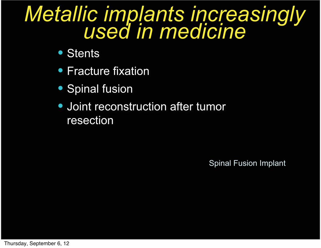
Metallic implants increasingly used in medicine
� Stents� Fracture fixation� Spinal fusion� Joint reconstruction after tumor
resection
Spinal Fusion Implant
Thursday, September 6, 12

Metallic implants increasingly used in medicine
� Stents� Fracture fixation� Spinal fusion� Joint reconstruction after tumor
resection
Spinal Fusion Implant
Thursday, September 6, 12

Total Knee Replacements� Total knee replacements (TKRs) increasing in
prevalence� In 2006: >540,000 primary TKRs and 39,000
revision TKRs� 2005 to 2030: Primary and revision total knee
arthroplasty expected to grow 673%
• ������������ �������� ����������������������� �������������������������� ���������������������������� �������������������X-ray of osteolysis
Thursday, September 6, 12

Osteosarcoma Pre-op
Motivation� MRI is the method of choice for examination of joints� Evaluation of metallic implants is now limited to x-ray or
CT scan with artifacts� MRI is extremely limited around metal implants due to
artifacts (signal loss and distortion)� Goal: Enable the routine use of MRI around metal
Thursday, September 6, 12

Osteosarcoma Pre-opPost-op x-ray Post-op CT w/ artifact
Motivation� MRI is the method of choice for examination of joints� Evaluation of metallic implants is now limited to x-ray or
CT scan with artifacts� MRI is extremely limited around metal implants due to
artifacts (signal loss and distortion)� Goal: Enable the routine use of MRI around metal
Thursday, September 6, 12

Osteosarcoma Pre-op
Motivation� MRI is the method of choice for examination of joints� Evaluation of metallic implants is now limited to x-ray or
CT scan with artifacts� MRI is extremely limited around metal implants due to
artifacts (signal loss and distortion)� Goal: Enable the routine use of MRI around metal
Conventional MRI w/ artifact
Thursday, September 6, 12

Metal in MRI
Displacement artifacts near metal. During excitation, a selection gradient causes a frequency variation (black arrows) but frequency shifts cause highlighted spins to be excited in the wrong slice. During imaging readout, the gradient induces a frequency variation, and the off-resonant spin appears to be at the wrong location. The displacements lead to bulk distortion, signal loss and pile-up effects.
Brian Hargreaves, Ph.D.
Thursday, September 6, 12

MR imaging of patients with hardware:
Factors influencing visualization
Thursday, September 6, 12

MR imaging of patients with hardware:
Factors influencing visualization• Hardware
• Alloy type• Susceptibility
Thursday, September 6, 12
MR imaging of patients with hardware:
Factors influencing visualization• Hardware
• Alloy type• Susceptibility
• Geometry• Image matrix• Slice width
Thursday, September 6, 12

MR imaging of patients with hardware:
Factors influencing visualization• Hardware
• Alloy type• Susceptibility
• Geometry• Image matrix• Slice width
• Scan technique• Pulse sequence selection• Receiver bandwidth
Thursday, September 6, 12

Artifact Depends on Alloy Type
Thursday, September 6, 12

Artifact Depends on Alloy Type
Bad Metals• Cobalt chrome
• Moderate artifacts• Older hips• Bipolar hips• Knees
Thursday, September 6, 12

Artifact Depends on Alloy Type
Bad Metals• Cobalt chrome
• Moderate artifacts• Older hips• Bipolar hips• Knees
• Stainless steel/Fe• Large artifacts• Plates, screws
Thursday, September 6, 12

Susceptibility Depends on Field Strength
cor T1 SEcor IR
Imaging at 0.3T. 52 year old man with history of osteonecrosis, prior core decompression left hip, right bipolar hip (Courtesy of Ken Buckwalter, MD).
Thursday, September 6, 12

Susceptibility Depends on Field Strength
• Lower magnetic field strength may have some advantages over higher field strength imaging
Thursday, September 6, 12

Susceptibility Depends on Field Strength
• Lower magnetic field strength may have some advantages over higher field strength imaging
• Worst scenario would be 3.0T
Thursday, September 6, 12

Susceptibility Depends on Field Strength
• Lower magnetic field strength may have some advantages over higher field strength imaging
• Worst scenario would be 3.0T• New techniques may enable
3.0T Imaging around metal
Thursday, September 6, 12

Matrix and Slice
Thursday, September 6, 12

Matrix and Slice• Increased resolution (matrix) in frequency
direction reduces the pixel size and the conspicuousness of artifacts
Thursday, September 6, 12

Matrix and Slice• Increased resolution (matrix) in frequency
direction reduces the pixel size and the conspicuousness of artifacts
• Increased phase resolution does not affect artifact size
Thursday, September 6, 12

Matrix and Slice• Increased resolution (matrix) in frequency
direction reduces the pixel size and the conspicuousness of artifacts
• Increased phase resolution does not affect artifact size
• Decreased slice thickness reduces slice distortion
Thursday, September 6, 12

Matrix and Slice• Increased resolution (matrix) in frequency
direction reduces the pixel size and the conspicuousness of artifacts
• Increased phase resolution does not affect artifact size
• Decreased slice thickness reduces slice distortion
• BUT...
Thursday, September 6, 12

Matrix and Slice• Increased resolution (matrix) in frequency
direction reduces the pixel size and the conspicuousness of artifacts
• Increased phase resolution does not affect artifact size
• Decreased slice thickness reduces slice distortion
• BUT...• Decreased slice thickness and increased
matrix decrease SNR
Thursday, September 6, 12

Receiver Bandwidth• Increased bandwidth decreases
metal artifact• Also decreases blurring and
chemical shift• BUT....• Increased bandwidth results in
lower SNR
Thursday, September 6, 12

Technique: MRI Sequences
Thursday, September 6, 12

Technique: MRI Sequences• Bad Sequences
• Gradient echo• Chemical Fat Suppression (fat sat)• Spin echo
Thursday, September 6, 12

Technique: MRI Sequences• Bad Sequences
• Gradient echo• Chemical Fat Suppression (fat sat)• Spin echo
Thursday, September 6, 12

Technique: MRI Sequences• Bad Sequences
• Gradient echo• Chemical Fat Suppression (fat sat)• Spin echo
• Good Sequences• Fast Spin Echo• STIR• IDEAL• SEMAC or MAVRIC
Thursday, September 6, 12

MRI Techniques - Inversion Recovery (STIR)
• Suppresses fat signal• Good for metal • Less SNR than T2 FS• Useful as backup sequence
to T2 FS• Necessary at lower
magnetic fields, e.g. 0.5 T T2 FS
Thursday, September 6, 12

MRI Techniques - Inversion Recovery (STIR)
• Suppresses fat signal• Good for metal • Less SNR than T2 FS• Useful as backup sequence
to T2 FS• Necessary at lower
magnetic fields, e.g. 0.5 T T2 FSSTIR
Thursday, September 6, 12

Chemsat
Chemsat
IR
IR
Chemsat vs. IR
Thursday, September 6, 12

Conventional Scan Technique Summary
Thursday, September 6, 12

Conventional Scan Technique Summary
• Metal friendly pulse sequence• FSE and FSE IR
• Avoid fatsat• Longer echo train
• 19-21
Thursday, September 6, 12

Conventional Scan Technique Summary
• Metal friendly pulse sequence• FSE and FSE IR
• Avoid fatsat• Longer echo train
• 19-21
• Wide bandwidth• Siemens: 700-800 Hz/pixel
• nominally 150-200• GE: 64-128 kHz
• nominally 16-20
Thursday, September 6, 12

Scan Technique Summary
Thursday, September 6, 12

Scan Technique Summary• High matrix
• f512 x p320• f320 x p256
Thursday, September 6, 12

Scan Technique Summary• High matrix
• f512 x p320• f320 x p256
• Thinner slices
Thursday, September 6, 12

Scan Technique Summary• High matrix
• f512 x p320• f320 x p256
• Thinner slices• Frequency encode axis
away from the ROI
Thursday, September 6, 12

What if you need IV Gd?
Thursday, September 6, 12
What if you need IV Gd?
• Fatsat T1 or SPGR will fail near the hardware
Thursday, September 6, 12
What if you need IV Gd?
• Fatsat T1 or SPGR will fail near the hardware
• STIR may suppress enhancement
Thursday, September 6, 12

What if you need IV Gd?
• Fatsat T1 or SPGR will fail near the hardware
• STIR may suppress enhancement• Subtraction technique
• Pre contrast T1 SE or FSE, no fatsat• Post contrast, same sequence• Subtract series
Thursday, September 6, 12

What if you need IV Gd?
• Fatsat T1 or SPGR will fail near the hardware
• STIR may suppress enhancement• Subtraction technique
• Pre contrast T1 SE or FSE, no fatsat• Post contrast, same sequence• Subtract series
• IDEAL
Thursday, September 6, 12

*Reeder et al, Magn Res Med, 51(1):35-45, 2004
Water and fat precess at different frequencies
Acquire 3 images at different echo times (TE)
Iterative Least-Squares Reconstruction*
Calculate Separate:
Water Image
Fat Image
Recombined Image (with or without chemical shift correction giving in- or out of phase)
Dixon Imaging (IDEAL)
Thursday, September 6, 12

IDEAL Imaging in the spine
Radiograph T1W IDEAL FSE
Thursday, September 6, 12

Brachial Plexus Imaging - NF1
Fat-Sat T1W IDEAL FSE
Thursday, September 6, 12

Imaging around metal: IDEAL
Fat-Sat FSE IDEAL FSE
Thursday, September 6, 12

Advanced Methods for MR Imaging around
Metal
Thursday, September 6, 12

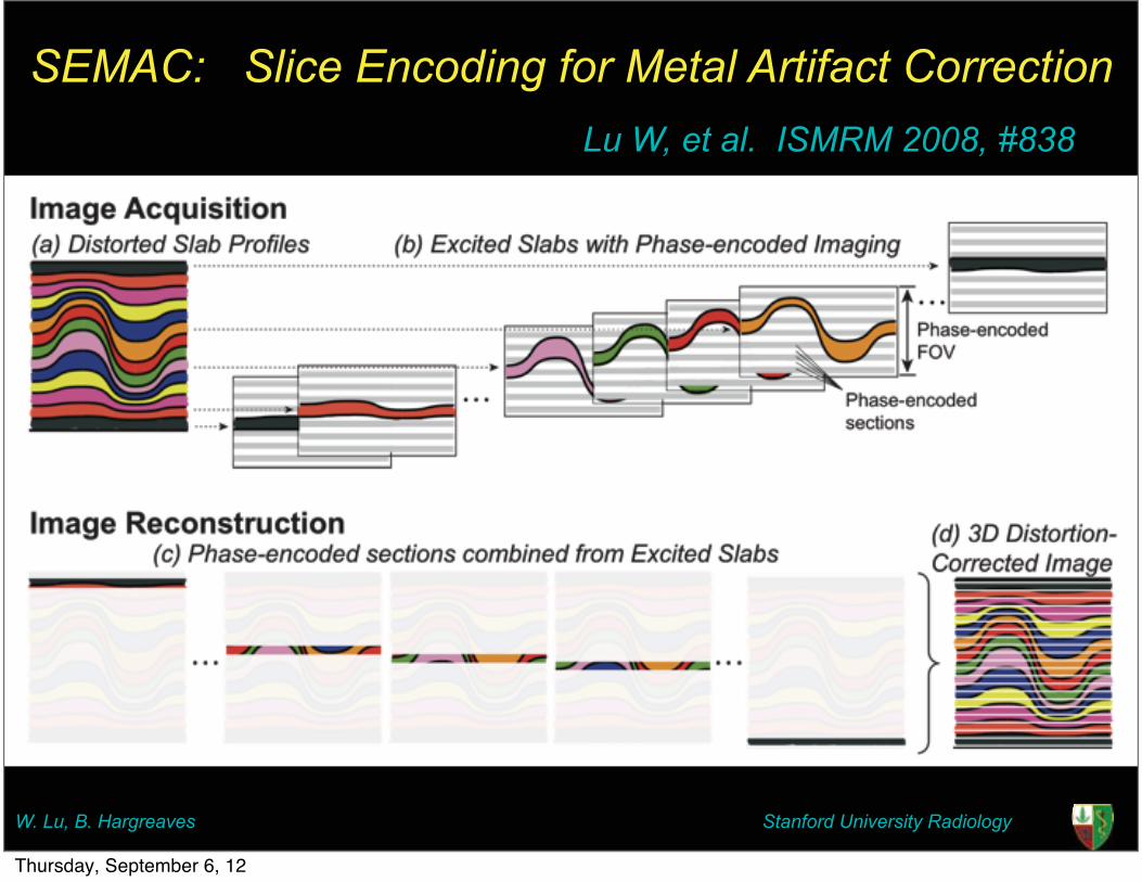
SEMAC: Slice Encoding for Metal Artifact Correction
Stanford University Radiology
Lu W, et al. ISMRM 2008, #838
W. Lu, B. Hargreaves
Thursday, September 6, 12

SEMAC: Slice Encoding for Metal Artifact Correction
Stanford University Radiology
Lu W, et al. ISMRM 2008, #838
W. Lu, B. Hargreaves
Thursday, September 6, 12
SEMAC: Slice Encoding for Metal Artifact Correction
Stanford University Radiology
Lu W, et al. ISMRM 2008, #838
W. Lu, B. Hargreaves
Thursday, September 6, 12
3D Correction of Metal Artifacts
Stanford University RadiologyW. Lu, B. Hargreaves
Thursday, September 6, 12

3D Correction of Metal Artifacts
Stanford University RadiologyW. Lu, B. Hargreaves
Spin Echo
Thursday, September 6, 12

3D Correction of Metal Artifacts
Stanford University RadiologyW. Lu, B. Hargreaves
Spin Echo VAT Spin Echo
Thursday, September 6, 12

3D Correction of Metal Artifacts
Stanford University RadiologyW. Lu, B. Hargreaves
Spin Echo VAT Spin Echo 3D Corrected(SEMAC)
Thursday, September 6, 12

• Collect multiple 3D FSE images at different T/R frequencies1:
• Multi-Acquisition Variable-Resonance Image Combination (MAVRIC)2
• Benefits:
• No slice distortion
• Maximum ΔB0 offset for any sub-image is ½ RF refocusing bandwidth:
~1 pixel max distortion
• Challenge: Acquisition time
MAVRIC
F
��
�
������� ������
������
On Resonance3D Image
+2kHz Off-Res -2kHz Off-Res
1. Koch et al, Proc ISMRM 2008, 12502. Koch et al, Mag Res Med, (in press)
Thursday, September 6, 12

SEMAC and MAVRIC - TKR at 1.5TFSE MAVRIC SEMAC
10 minute acquisition time for SEMAC and MAVRIC16 cm FOV, 256 by 128, slice thickness = 3mm, gap 0
SEMAC: ETL = 8, TR 4000, TE Min Full, BW 125MAVRIC ETL = 20, TR 2400, TE 20, BW 125
2X ARC for SEMAC and MAVRIC Thursday, September 6, 12
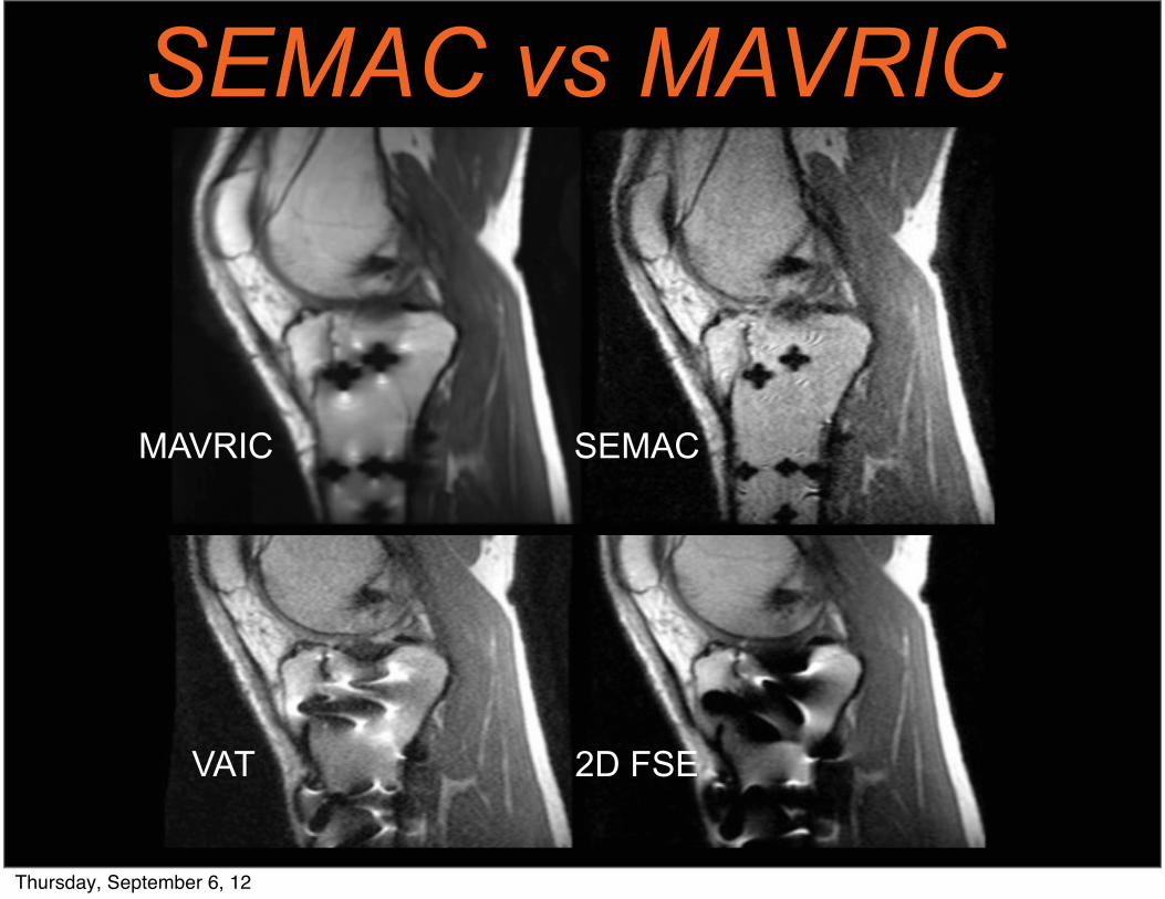
SEMAC vs MAVRIC
MAVRIC SEMAC
VAT 2D FSE
Thursday, September 6, 12

SEMAC – Flexible Contrast
Thursday, September 6, 12

SEMAC – Flexible Contrast
Thursday, September 6, 12

TKR
FSE SEMAC MAVRIC
Thursday, September 6, 12

Clinical ExperienceSubject Population (number) Imaging findings and change in management
Painful total knee (7) Patella tendon tear confirmed at surgery (1); Epicondylar axis for alignment (7)
Cancer follow-up (3) Tumor on imaging; confirmed at surgery (1); sent to biopsy (1); stable for follow-up (1)
Painful total hip (2) Fluid detected; hip aspiration performedPainful biceps repair Failed biceps repair confirmed at surgeryPain after c-spine fusion No recurrent disc pathology
Thursday, September 6, 12

Chondrosarcoma recurrence
T1 SEMAC PD SEMAC STIR SEMAC
Limb-sparing resection performedThursday, September 6, 12

FSE PD SEMAC
Painful Total Knee ReplacementIR SEMAC
Patella Tendon Rupture (Surgery proven)
Thursday, September 6, 12

Infection?
Needle Aspiration
Localization of fluid for aspirationThursday, September 6, 12

Infection?
Needle Aspiration
Localization of fluid for aspirationThursday, September 6, 12

Painful Total Hip ReplacementT1 FSE
PD SEMACT1 SEMAC
Fluid collection near total hip aspiratedThursday, September 6, 12

Painful Total Hip ReplacementT1 FSE
PD SEMACT1 SEMAC
Fluid collection near total hip aspiratedThursday, September 6, 12

Imaging of Spinal Fusion
Painful spinal stenosis – surgically treated
Thursday, September 6, 12
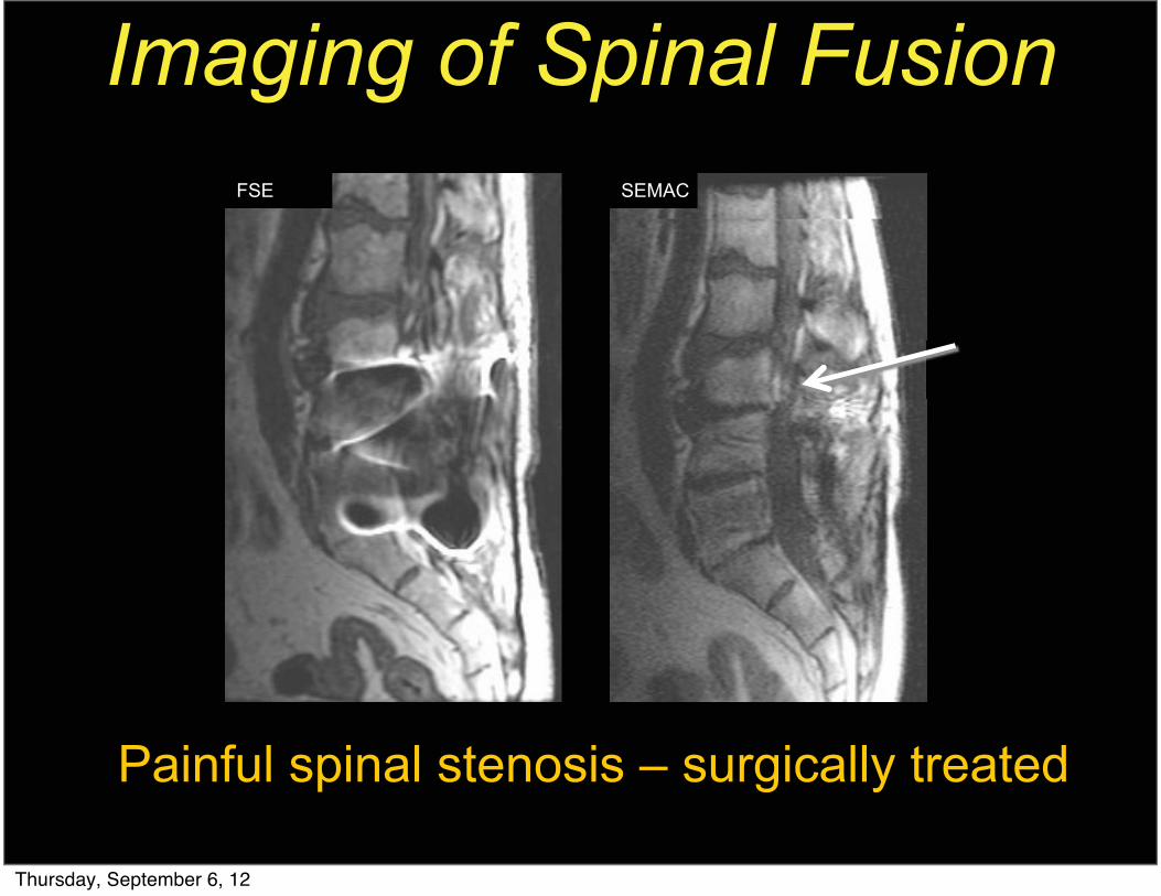
Imaging of Spinal FusionSEMACFSE
Painful spinal stenosis – surgically treated
Thursday, September 6, 12

Imaging of Spinal Fusion
Painful spinal stenosis – surgically treated
Thursday, September 6, 12

Hybrid Technique - 3.0T
Thursday, September 6, 12

Summary
Thursday, September 6, 12

Summary• Orthopedic Hardware is increasingly
common• Several MR techniques exist to minimize
metal artifact• Increase receiver bandwidth• Thin slices• FSE• IDEAL, SEMAC, MAVRIC
• Advanced MRI techniques for artifact reduction show promise to make imaging around these implants routine
Thursday, September 6, 12