imaging of the paranasal sinuses and in-office ct · imagingof the paranasal sinuses ... given the...
TRANSCRIPT
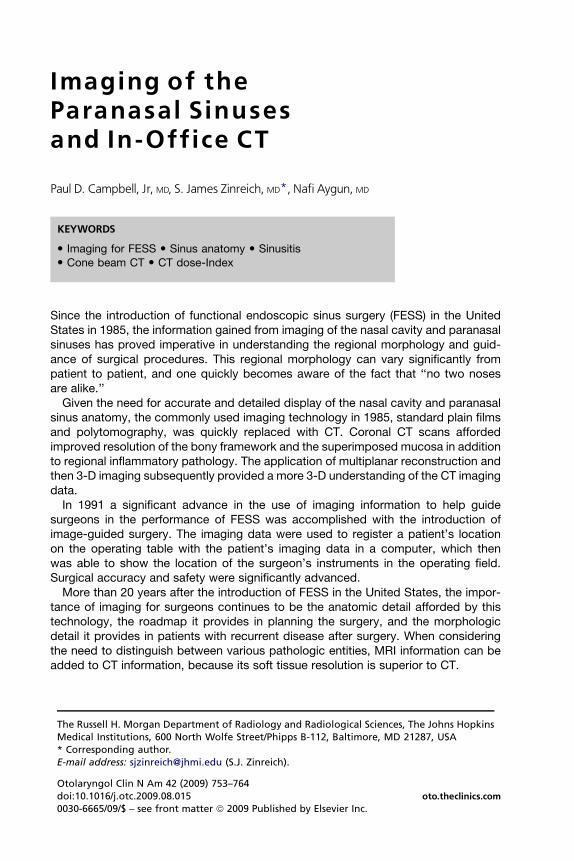
Imaging of theParanasal Sinusesand In -Office CT
Paul D. Campbell, Jr, MD, S. James Zinreich, MD*, Nafi Aygun, MD
KEYWORDS
� Imaging for FESS � Sinus anatomy � Sinusitis� Cone beam CT � CT dose-Index
Since the introduction of functional endoscopic sinus surgery (FESS) in the UnitedStates in 1985, the information gained from imaging of the nasal cavity and paranasalsinuses has proved imperative in understanding the regional morphology and guid-ance of surgical procedures. This regional morphology can vary significantly frompatient to patient, and one quickly becomes aware of the fact that ‘‘no two nosesare alike.’’
Given the need for accurate and detailed display of the nasal cavity and paranasalsinus anatomy, the commonly used imaging technology in 1985, standard plain filmsand polytomography, was quickly replaced with CT. Coronal CT scans affordedimproved resolution of the bony framework and the superimposed mucosa in additionto regional inflammatory pathology. The application of multiplanar reconstruction andthen 3-D imaging subsequently provided a more 3-D understanding of the CT imagingdata.
In 1991 a significant advance in the use of imaging information to help guidesurgeons in the performance of FESS was accomplished with the introduction ofimage-guided surgery. The imaging data were used to register a patient’s locationon the operating table with the patient’s imaging data in a computer, which thenwas able to show the location of the surgeon’s instruments in the operating field.Surgical accuracy and safety were significantly advanced.
More than 20 years after the introduction of FESS in the United States, the impor-tance of imaging for surgeons continues to be the anatomic detail afforded by thistechnology, the roadmap it provides in planning the surgery, and the morphologicdetail it provides in patients with recurrent disease after surgery. When consideringthe need to distinguish between various pathologic entities, MRI information can beadded to CT information, because its soft tissue resolution is superior to CT.
The Russell H. Morgan Department of Radiology and Radiological Sciences, The Johns HopkinsMedical Institutions, 600 North Wolfe Street/Phipps B-112, Baltimore, MD 21287, USA* Corresponding author.E-mail address: [email protected] (S.J. Zinreich).
Otolaryngol Clin N Am 42 (2009) 753–764doi:10.1016/j.otc.2009.08.015 oto.theclinics.com0030-6665/09/$ – see front matter ª 2009 Published by Elsevier Inc.
Campbell et al754
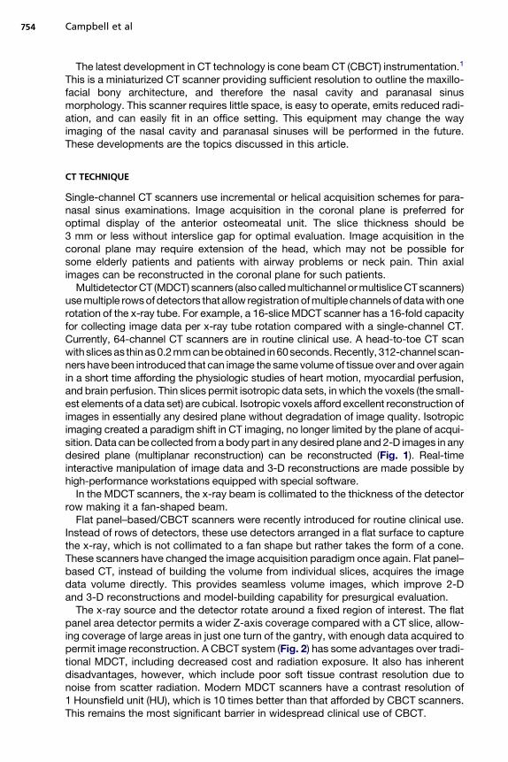
The latest development in CT technology is cone beam CT (CBCT) instrumentation.1
This is a miniaturized CT scanner providing sufficient resolution to outline the maxillo-facial bony architecture, and therefore the nasal cavity and paranasal sinusmorphology. This scanner requires little space, is easy to operate, emits reduced radi-ation, and can easily fit in an office setting. This equipment may change the wayimaging of the nasal cavity and paranasal sinuses will be performed in the future.These developments are the topics discussed in this article.
CT TECHNIQUE
Single-channel CT scanners use incremental or helical acquisition schemes for para-nasal sinus examinations. Image acquisition in the coronal plane is preferred foroptimal display of the anterior osteomeatal unit. The slice thickness should be3 mm or less without interslice gap for optimal evaluation. Image acquisition in thecoronal plane may require extension of the head, which may not be possible forsome elderly patients and patients with airway problems or neck pain. Thin axialimages can be reconstructed in the coronal plane for such patients.
Multidetector CT (MDCT) scanners (also called multichannel or multislice CT scanners)use multiple rows of detectors that allow registration of multiple channels of data with onerotation of the x-ray tube. For example, a 16-slice MDCT scanner has a 16-fold capacityfor collecting image data per x-ray tube rotation compared with a single-channel CT.Currently, 64-channel CT scanners are in routine clinical use. A head-to-toe CT scanwith slices as thinas 0.2 mm can beobtained in60seconds.Recently, 312-channel scan-ners have been introduced that can image the same volume of tissue over and over againin a short time affording the physiologic studies of heart motion, myocardial perfusion,and brain perfusion. Thin slices permit isotropic data sets, in which the voxels (the small-est elements of a data set) are cubical. Isotropic voxels afford excellent reconstruction ofimages in essentially any desired plane without degradation of image quality. Isotropicimaging created a paradigm shift in CT imaging, no longer limited by the plane of acqui-sition. Data can be collected from a body part in any desired plane and 2-D images in anydesired plane (multiplanar reconstruction) can be reconstructed (Fig. 1). Real-timeinteractive manipulation of image data and 3-D reconstructions are made possible byhigh-performance workstations equipped with special software.
In the MDCT scanners, the x-ray beam is collimated to the thickness of the detectorrow making it a fan-shaped beam.
Flat panel–based/CBCT scanners were recently introduced for routine clinical use.Instead of rows of detectors, these use detectors arranged in a flat surface to capturethe x-ray, which is not collimated to a fan shape but rather takes the form of a cone.These scanners have changed the image acquisition paradigm once again. Flat panel–based CT, instead of building the volume from individual slices, acquires the imagedata volume directly. This provides seamless volume images, which improve 2-Dand 3-D reconstructions and model-building capability for presurgical evaluation.
The x-ray source and the detector rotate around a fixed region of interest. The flatpanel area detector permits a wider Z-axis coverage compared with a CT slice, allow-ing coverage of large areas in just one turn of the gantry, with enough data acquired topermit image reconstruction. A CBCT system (Fig. 2) has some advantages over tradi-tional MDCT, including decreased cost and radiation exposure. It also has inherentdisadvantages, however, which include poor soft tissue contrast resolution due tonoise from scatter radiation. Modern MDCT scanners have a contrast resolution of1 Hounsfield unit (HU), which is 10 times better than that afforded by CBCT scanners.This remains the most significant barrier in widespread clinical use of CBCT.
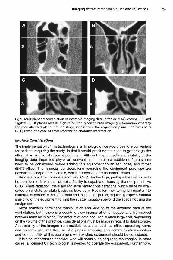
Fig.1. Multiplanar reconstruction of isotropic imaging data in the axial (A), coronal (B), andsagittal (C, D) planes reveals high-resolution reconstructed imaging information wherebythe reconstructed planes are indistinguishable from the acquisition plane. The cross hairs(A–C) reveal the ease of cross-referencing anatomic information.
Imaging of the Paranasal Sinuses and In-Office CT 755
In-office Considerations
The implementation of this technology in a rhinologic office would be more convenientfor patients requiring the study, in that it would preclude the need to go through theeffort of an additional office appointment. Although the immediate availability of theimaging data improves physician convenience, there are additional factors thatneed to be considered before adding this equipment to an ear, nose, and throat(ENT) office. The financial considerations regarding the equipment purchase arebeyond the scope of this article, which addresses only technical issues.
Before a practice considers acquiring CBCT technology, perhaps the first issue tobe considered is whether or not a facility is capable of housing the equipment. AsCBCT emits radiation, there are radiation safety considerations, which must be eval-uated on a state-by-state basis, as laws vary. Radiation monitoring is important tominimize exposure to the office staff and the general public, requiring proper structuralshielding of the equipment to limit the scatter radiation beyond the space housing theequipment.
Most scanners permit the manipulation and viewing of the acquired data at theworkstation, but if there is a desire to view images at other locations, a high-speednetwork must be in place. The amount of data acquired is often large and, dependingon the volume of the practice, considerations must be made in regard to data storage.Accessibility of the images from multiple locations, such as office, operating room,and so forth, requires the use of a picture archiving and communications systemand compatibility of this equipment with existing equipment should be considered.
It is also important to consider who will actually be acquiring the images. In mostcases, a licensed CT technologist is needed to operate the equipment. Furthermore,
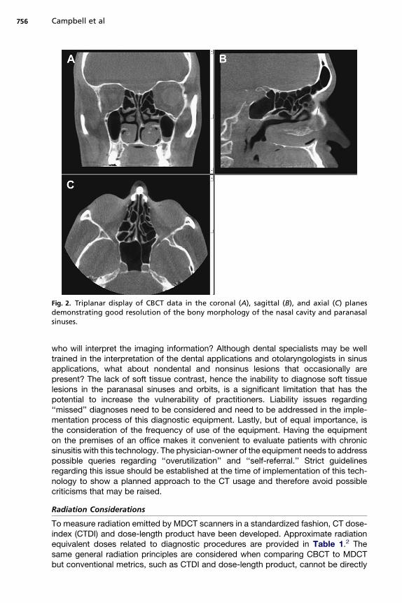
Fig. 2. Triplanar display of CBCT data in the coronal (A), sagittal (B), and axial (C) planesdemonstrating good resolution of the bony morphology of the nasal cavity and paranasalsinuses.
Campbell et al756
who will interpret the imaging information? Although dental specialists may be welltrained in the interpretation of the dental applications and otolaryngologists in sinusapplications, what about nondental and nonsinus lesions that occasionally arepresent? The lack of soft tissue contrast, hence the inability to diagnose soft tissuelesions in the paranasal sinuses and orbits, is a significant limitation that has thepotential to increase the vulnerability of practitioners. Liability issues regarding‘‘missed’’ diagnoses need to be considered and need to be addressed in the imple-mentation process of this diagnostic equipment. Lastly, but of equal importance, isthe consideration of the frequency of use of the equipment. Having the equipmenton the premises of an office makes it convenient to evaluate patients with chronicsinusitis with this technology. The physician-owner of the equipment needs to addresspossible queries regarding ‘‘overutilization’’ and ‘‘self-referral.’’ Strict guidelinesregarding this issue should be established at the time of implementation of this tech-nology to show a planned approach to the CT usage and therefore avoid possiblecriticisms that may be raised.
Radiation Considerations
To measure radiation emitted by MDCT scanners in a standardized fashion, CT dose-index (CTDI) and dose-length product have been developed. Approximate radiationequivalent doses related to diagnostic procedures are provided in Table 1.2 Thesame general radiation principles are considered when comparing CBCT to MDCTbut conventional metrics, such as CTDI and dose-length product, cannot be directly
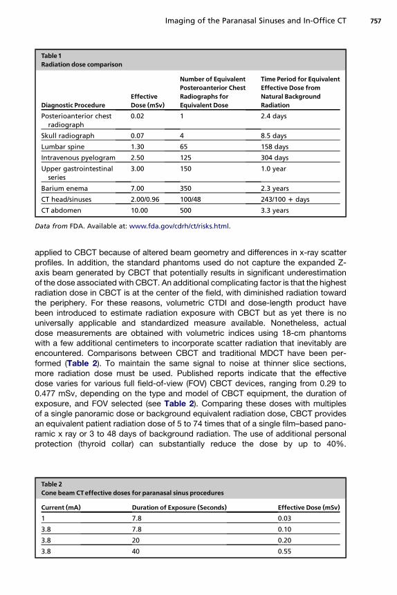
Table 1Radiation dose comparison
Diagnostic ProcedureEffectiveDose (mSv)
Number of EquivalentPosteroanterior ChestRadiographs forEquivalent Dose
Time Period for EquivalentEffective Dose fromNatural BackgroundRadiation
Posterioanterior chestradiograph
0.02 1 2.4 days
Skull radiograph 0.07 4 8.5 days
Lumbar spine 1.30 65 158 days
Intravenous pyelogram 2.50 125 304 days
Upper gastrointestinalseries
3.00 150 1.0 year
Barium enema 7.00 350 2.3 years
CT head/sinuses 2.00/0.96 100/48 243/100 1 days
CT abdomen 10.00 500 3.3 years
Data from FDA. Available at: www.fda.gov/cdrh/ct/risks.html.
Imaging of the Paranasal Sinuses and In-Office CT 757
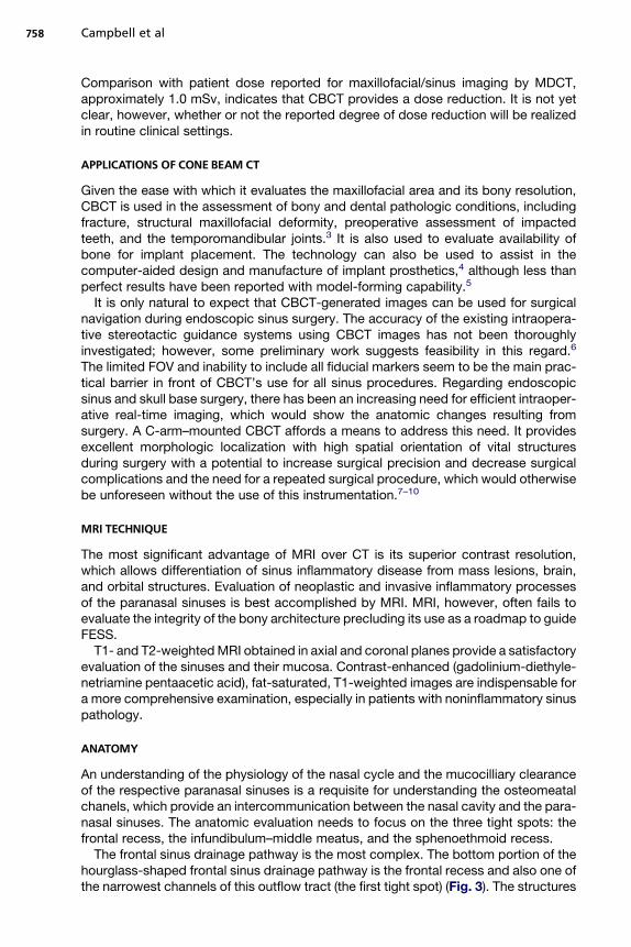
applied to CBCT because of altered beam geometry and differences in x-ray scatterprofiles. In addition, the standard phantoms used do not capture the expanded Z-axis beam generated by CBCT that potentially results in significant underestimationof the dose associated with CBCT. An additional complicating factor is that the highestradiation dose in CBCT is at the center of the field, with diminished radiation towardthe periphery. For these reasons, volumetric CTDI and dose-length product havebeen introduced to estimate radiation exposure with CBCT but as yet there is nouniversally applicable and standardized measure available. Nonetheless, actualdose measurements are obtained with volumetric indices using 18-cm phantomswith a few additional centimeters to incorporate scatter radiation that inevitably areencountered. Comparisons between CBCT and traditional MDCT have been per-formed (Table 2). To maintain the same signal to noise at thinner slice sections,more radiation dose must be used. Published reports indicate that the effectivedose varies for various full field-of-view (FOV) CBCT devices, ranging from 0.29 to0.477 mSv, depending on the type and model of CBCT equipment, the duration ofexposure, and FOV selected (see Table 2). Comparing these doses with multiplesof a single panoramic dose or background equivalent radiation dose, CBCT providesan equivalent patient radiation dose of 5 to 74 times that of a single film–based pano-ramic x ray or 3 to 48 days of background radiation. The use of additional personalprotection (thyroid collar) can substantially reduce the dose by up to 40%.
Table 2Cone beam CTeffective doses for paranasal sinus procedures
Current (mA) Duration of Exposure (Seconds) Effective Dose (mSv)1 7.8 0.03
3.8 7.8 0.10
3.8 20 0.20
3.8 40 0.55
Campbell et al758
Comparison with patient dose reported for maxillofacial/sinus imaging by MDCT,approximately 1.0 mSv, indicates that CBCT provides a dose reduction. It is not yetclear, however, whether or not the reported degree of dose reduction will be realizedin routine clinical settings.
APPLICATIONS OF CONE BEAM CT
Given the ease with which it evaluates the maxillofacial area and its bony resolution,CBCT is used in the assessment of bony and dental pathologic conditions, includingfracture, structural maxillofacial deformity, preoperative assessment of impactedteeth, and the temporomandibular joints.3 It is also used to evaluate availability ofbone for implant placement. The technology can also be used to assist in thecomputer-aided design and manufacture of implant prosthetics,4 although less thanperfect results have been reported with model-forming capability.5
It is only natural to expect that CBCT-generated images can be used for surgicalnavigation during endoscopic sinus surgery. The accuracy of the existing intraopera-tive stereotactic guidance systems using CBCT images has not been thoroughlyinvestigated; however, some preliminary work suggests feasibility in this regard.6
The limited FOV and inability to include all fiducial markers seem to be the main prac-tical barrier in front of CBCT’s use for all sinus procedures. Regarding endoscopicsinus and skull base surgery, there has been an increasing need for efficient intraoper-ative real-time imaging, which would show the anatomic changes resulting fromsurgery. A C-arm–mounted CBCT affords a means to address this need. It providesexcellent morphologic localization with high spatial orientation of vital structuresduring surgery with a potential to increase surgical precision and decrease surgicalcomplications and the need for a repeated surgical procedure, which would otherwisebe unforeseen without the use of this instrumentation.7–10
MRI TECHNIQUE
The most significant advantage of MRI over CT is its superior contrast resolution,which allows differentiation of sinus inflammatory disease from mass lesions, brain,and orbital structures. Evaluation of neoplastic and invasive inflammatory processesof the paranasal sinuses is best accomplished by MRI. MRI, however, often fails toevaluate the integrity of the bony architecture precluding its use as a roadmap to guideFESS.
T1- and T2-weighted MRI obtained in axial and coronal planes provide a satisfactoryevaluation of the sinuses and their mucosa. Contrast-enhanced (gadolinium-diethyle-netriamine pentaacetic acid), fat-saturated, T1-weighted images are indispensable fora more comprehensive examination, especially in patients with noninflammatory sinuspathology.
ANATOMY
An understanding of the physiology of the nasal cycle and the mucocilliary clearanceof the respective paranasal sinuses is a requisite for understanding the osteomeatalchanels, which provide an intercommunication between the nasal cavity and the para-nasal sinuses. The anatomic evaluation needs to focus on the three tight spots: thefrontal recess, the infundibulum–middle meatus, and the sphenoethmoid recess.
The frontal sinus drainage pathway is the most complex. The bottom portion of thehourglass-shaped frontal sinus drainage pathway is the frontal recess and also one ofthe narrowest channels of this outflow tract (the first tight spot) (Fig. 3). The structures
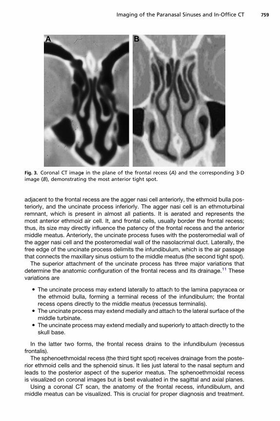
Fig. 3. Coronal CT image in the plane of the frontal recess (A) and the corresponding 3-Dimage (B), demonstrating the most anterior tight spot.
Imaging of the Paranasal Sinuses and In-Office CT 759
adjacent to the frontal recess are the agger nasi cell anteriorly, the ethmoid bulla pos-teriorly, and the uncinate process inferiorly. The agger nasi cell is an ethmoturbinalremnant, which is present in almost all patients. It is aerated and represents themost anterior ethmoid air cell. It, and frontal cells, usually border the frontal recess;thus, its size may directly influence the patency of the frontal recess and the anteriormiddle meatus. Anteriorly, the uncinate process fuses with the posteromedial wall ofthe agger nasi cell and the posteromedial wall of the nasolacrimal duct. Laterally, thefree edge of the uncinate process delimits the infundibulum, which is the air passagethat connects the maxillary sinus ostium to the middle meatus (the second tight spot).
The superior attachment of the uncinate process has three major variations thatdetermine the anatomic configuration of the frontal recess and its drainage.11 Thesevariations are
� The uncinate process may extend laterally to attach to the lamina papyracea orthe ethmoid bulla, forming a terminal recess of the infundibulum; the frontalrecess opens directly to the middle meatus (recessus terminalis).� The uncinate process may extend medially and attach to the lateral surface of the
middle turbinate.� The uncinate process may extend medially and superiorly to attach directly to the
skull base.
In the latter two forms, the frontal recess drains to the infundibulum (recessusfrontalis).
The sphenoethmoidal recess (the third tight spot) receives drainage from the poste-rior ethmoid cells and the sphenoid sinus. It lies just lateral to the nasal septum andleads to the posterior aspect of the superior meatus. The sphenoethmoidal recessis visualized on coronal images but is best evaluated in the sagittal and axial planes.
Using a coronal CT scan, the anatomy of the frontal recess, infundibulum, andmiddle meatus can be visualized. This is crucial for proper diagnosis and treatment.
Campbell et al760
Using the real-time multiplanar reconstruction capabilities of modern imaging work-stations, understanding of the complex anatomy of these regions can be advancedconsiderably. The authors found oblique coronal reconstructions with 20� craniocau-dal angulation and oblique sagittal reconstructions with 5� to 10� lateromedial angu-lation particularly helpful in demonstrating the frontal-recess–agger nasicell–uncinate process relationship. Routine axial images show the sphenoethmoidalrecess to the authors’ satisfaction but minimally obliqued sagittal reconstructionsbest demonstrate the sphenoethmoidal recess–superior meatus relationship.
The authors prefer to evaluate the imaging information starting with the most ante-rior images showing the frontal sinuses and systematically proceeding posteriorlythrough the sphenoid sinus specifically studying the anatomy surrounding the tightspots. With completion of this task, an evaluation focusing on the nasal septum andproceeding laterally affords additional information regarding the osteomeatal chan-nels, specifically the turbinate relationship to the uncinate process, frontal cells, andanterior and posterior ethmoid cells.12,13
APPEARANCE OF RHINOSINUSITIS
The most common indication for sinus imaging is chronic rhinosinusitis (CRS). CT isthe imaging standard for evaluation of CRS.14 The CT signs suggestive of CRS includediffuse or focal mucosal thickening, with partial or complete opacification of theparanasal sinuses; bone remodeling with uniform thickening caused by osteitis fromadjacent chronic mucosal inflammation; and polyposis. Thickening and sclerosis ofthe bony walls of the sinuses are at least in part secondary to the spread of the inflam-mation through the haversian system within the bone.15,16
The distribution of the inflammatory mucosal changes in the nasal cavity andsinuses may provide a clue to the focus of mechanical obstruction, which can be pin-pointed by evaluating the sinus drainage pathways. Although CT provides excellentinformation about the extent and distribution of mucosal disease and the status ofthe nasal air passages, it does not yield much information regarding the cause ofthe changes (eg, infection, allergies, granulomatous inflammation, postsurgicalscarring, and so forth).
In the acute state, the viscosity of the inflammatory process is of intermediateattenuation on CT (10–25 HU). In the more chronic state, sinus secretions becomethickened and concentrated, and the CT attenuation increases, with density measure-ments of 30 to 60 HU.17 In the acute state, the obstruction of a specific sinus is fol-lowed by a circumferential mucosal edema/inflammation and fluid exudation,represented on CT by an air fluid level and uniform circumferential soft tissue thick-ening. Contrasted CT and T1-weighted MRI show a uniform uninterrupted enhance-ment adjacent to the peripheral sinus bony outline. This is characteristic of aninflammatory process within the paranasal sinuses.
Antrochoanal and sphenochoanal polyps appear as well-defined masses that arisefrom the maxillary or sphenoid sinus and extend to the choana through the middlemeatus or sphenoethmoid recess, respectively. They can present as nasopharyngealmasses. It is important to recognize their origin and relationship to the maxillary orsphenoid ostium in treatment planning.
Retention cysts are common incidental findings on imaging studies and are seen aswell-defined rounded masses, typically on the maxillary sinus floor. Their clinicalsignificance is not clear.18 They may become symptomatic if large enough to interferewith drainage pathways.19
Imaging of the Paranasal Sinuses and In-Office CT 761
Mucocele, a complication of CRS, results from a persistant obstruction of the sinusdrainage and subsequent expansion of the sinus. Mucoceles are seen morecommonly in the ethmoid and frontal sinuses and present with symptoms secondaryto compression of the adjacent structures, in addition to the usual symptoms of CRS.
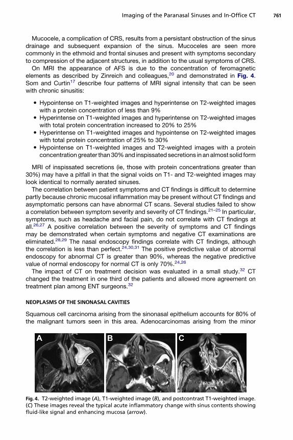
On MRI the appearance of AFS is due to the concentration of feromagneticelements as described by Zinreich and colleagues,20 and demonstrated in Fig. 4.Som and Curtin17 describe four patterns of MRI signal intensity that can be seenwith chronic sinusitis:
� Hypointense on T1-weighted images and hyperintense on T2-weighted imageswith a protein concentration of less than 9%� Hyperintense on T1-weighted images and hyperintense on T2-weighted images
with total protein concentration increased to 20% to 25%� Hyperintense on T1-weighted images and hypointense on T2-weighted images
with total protein concentration of 25% to 30%� Hypointense on T1-weighted images and T2-weighted images with a protein
concentration greater than 30% and inspissated secretions in an almost solid form
MRI of inspissated secretions (ie, those with protein concentrations greater than30%) may have a pitfall in that the signal voids on T1- and T2-weighted images maylook identical to normally aerated sinuses.
The correlation between patient symptoms and CT findings is difficult to determinepartly because chronic mucosal inflammation may be present without CT findings andasymptomatic persons can have abnormal CT scans. Several studies failed to showa correlation between symptom severity and severity of CT findings.21–25 In particular,symptoms, such as headache and facial pain, do not correlate with CT findings atall.26,27 A positive correlation between the severity of symptoms and CT findingsmay be demonstrated when certain symptoms and negative CT examinations areeliminated.28,29 The nasal endoscopy findings correlate with CT findings, althoughthe correlation is less than perfect.24,30,31 The positive predictive value of abnormalendoscopy for abnormal CT is greater than 90%, whereas the negative predictivevalue of normal endoscopy for normal CT is only 70%.24,26
The impact of CT on treatment decision was evaluated in a small study.32 CTchanged the treatment in one third of the patients and allowed more agreement ontreatment plan among ENT surgeons.32
NEOPLASMS OF THE SINONASAL CAVITIES
Squamous cell carcinoma arising from the sinonasal epithelium accounts for 80% ofthe malignant tumors seen in this area. Adenocarcinomas arising from the minor
Fig. 4. T2-weighted image (A), T1-weighted image (B), and postcontrast T1-weighted image.(C) These images reveal the typical acute inflammatory change with sinus contents showingfluid-like signal and enhancing mucosa (arrow).
Campbell et al762
salivary glands interspersed in the sinonasal mucosa account for up to 10% of themalignant tumors. Melanomas are responsible for 5% of sinonasal malignant tumors.Less common malignant tumors of the sinonasal cavities include olfactory neuroblas-toma, lymphomas, and sarcomas. A detailed discussion of these individual entities isbeyond the scope of this article.
On CT, neoplasms are recognized by their invasive character and bone erosion.Focal bone erosion with or without expansion is evident. Depending on size and exten-sion, the mass may erode through the bony confines of a particular sinus and invadethe tissues peripheral to the sinus bony architecture. The precise extension can bebest determined with a contrast-enhanced MRI study. The mass is usually of lowersignal intensity and its contrast enhancement is less than that of an inflammatoryprocess. The uniform enhancement seen peripherally within a sinus cavity with inflam-mation is interrupted as the mass extends beyond the confines of the sinus cavity.Additionally, certain characteristics are associated with specific neoplasms. Peripheralcysts are associated with esthesioneuroblastomas. A serpiginous cerebral sulcal–likeenhancement is associated with inverted papilomas.
SUMMARY
Two and a half decades after the introduction of FESS in the United States, the role ofimaging with respect to this surgical procedure is the information it provides regardingthe anatomic detail of the nasal cavity and paranasal sinuses. The imaging informationaffords surgical planning and guidance. Furthermore, when considering the applica-tion of CT and MRI, the information derived from these technologies helps narrowthe differential diagnosis and helps define the causes of various pathologic entitiesconfronted in this area.
As FESS has evolved since 1985, so has imaging technology and its application withregards to this surgery. Of significant note is the introduction of image-guided surgery.Image guidance further revolutionized the use of imaging information in that itprovided a direct confirmation of anatomic structures and improved the guidanceand safety of the surgical act.
The introduction of CBCT begins a new phase of change in the use of imaging forthe evaluation of maxillofacial pathology. Its presence in the office environmentaddresses issues related to the patient and physician ‘‘convenience factor.’’ The radi-ation exposure and diagnostic issues are new topics with which ENT offices need todeal (in most instances for the first time), to adhere to the various regulatory measuresand potential risks introduced by this technology in the in-office setting.
Regarding the use of CBCT in the OR setting, early results seem to show augmentedbenefits provided by image-guided surgery, in that it provides confirmation of theextent of surgery before patients leave the operating room, therefore providing accu-rate confirmation of the surgical objective.
REFERENCES
1. Mozzo P, Procacci C, Tacconi A, et al. A new volumetric CT machine for dentalimaging based on the cone-beam technique: preliminary results. Eur Radiol1998;8:1558–64.
2. FDA. Available at: www.fda.gov/cdrh/ct/risks.html.3. Thomas SL. Application of cone-beam CT in the office setting. Dent Clin North Am
2008;52:753–9, vi.4. Scarfe WC, Farman AG. What is cone-beam CT and how does it work? Dent Clin
North Am 2008;52:707–30, v.
Imaging of the Paranasal Sinuses and In-Office CT 763
5. Hassan B, van der Stelt P, Sanderink G. Accuracy of three-dimensional measure-ments obtained from cone beam computed tomography surface-renderedimages for cephalometric analysis: influence of patient scanning position. Eur JOrthod 2009;31:129–34.
6. Eggers G, Muhling J, Hofele C. Clinical use of navigation based on cone-beamcomputer tomography in maxillofacial surgery. Br J Oral Maxillofac Surg 2009.
7. Chan Y, Siewerdsen JH, Rafferty MA, et al. Cone-beam computed tomography ona mobile C-arm: novel intraoperative imaging technology for guidance of headand neck surgery. J Otolaryngol Head Neck Surg 2008;37:81–90.
8. Bachar G, Barker E, Nithiananthan S, et al. Three-dimensional tomosynthesis andcone-beam computed tomography: an experimental study for fast, low-dose in-traoperative imaging technology for guidance of sinus and skull base surgery.Laryngoscope 2009;119:434–41.
9. Rafferty MA, Siewerdsen JH, Chan Y, et al. Intraoperative cone-beam CT for guid-ance of temporal bone surgery. Otolaryngol Head Neck Surg 2006;134:801–8.
10. Rafferty MA, Siewerdsen JH, Chan Y, et al. Investigation of C-arm cone-beamCT-guided surgery of the frontal recess. Laryngoscope 2005;115:2138–43.
11. Daniels DL, Mafee MF, Smith MM, et al. The frontal sinus drainage pathway andrelated structures. AJNR Am J Neuroradiol 2003;24:1618–27.
12. Zammit-Maempel I, Chadwick CL, Willis SP. Radiation dose to the lens of eye andthyroid gland in paranasal sinus multislice CT. Br J Radiol 2003;76:418–20.
13. Tack D, Widelec J, De Maertelaer V, et al. Comparison between low-dose andstandard-dose multidetector CT in patients with suspected chronic sinusitis.AJR Am J Roentgenol 2003;181:939–44.
14. Benninger MS, Ferguson BJ, Hadley JA, et al. Adult chronic rhinosinusitis: defini-tions, diagnosis, epidemiology, and pathophysiology. Otolaryngol Head NeckSurg 2003;129:S1–32.
15. Perloff JR, Gannon FH, Bolger WE, et al. Bone involvement in sinusitis: anapparent pathway for the spread of disease. Laryngoscope 2000;110:2095–9.
16. Khalid AN, Hunt J, Perloff JR, et al. The role of bone in chronic rhinosinusitis.Laryngoscope 2002;112:1951–7.
17. Som PM, Curtin HD. Chronic inflammatory sinonasal diseases including fungalinfections. The role of imaging. Radiol Clin North Am 1993;31:33–44.
18. Bhattacharyya N. Do maxillary sinus retention cysts reflect obstructive sinusphenomena? Arch Otolaryngol Head Neck Surg 2000;126:1369–71.
19. Hadar T, Shvero J, Nageris BI, et al. Mucus retention cyst of the maxillary sinus:the endoscopic approach. Br J Oral Maxillofac Surg 2000;38:227–9.
20. Zinreich S, Kennedy D, Malat J, et al. Diagnosis with CT and MR imaging. Radi-ology 1998;169(2):439–44.
21. Bhattacharyya T, Piccirillo J, Wippold FJ 2nd. Relationship between patient-based descriptions of sinusitis and paranasal sinus computed tomographic find-ings. Arch Otolaryngol Head Neck Surg 1997;123:1189–92.
22. Ashraf N, Bhattacharyya N. Determination of the ‘‘incidental’’ Lund score forthe staging of chronic rhinosinusitis. Otolaryngol Head Neck Surg 2001;125:483–6.
23. Stewart MG, Sicard MW, Piccirillo JF, et al. Severity staging in chronic sinusitis:are CT scan findings related to patient symptoms? Am J Rhinol 1999;13:161–7.
24. Stankiewicz JA, Chow JM. Nasal endoscopy and the definition and diagnosis ofchronic rhinosinusitis. Otolaryngol Head Neck Surg 2002;126:623–7.
25. Stankiewicz JA, Chow JM. A diagnostic dilemma for chronic rhinosinusitis: defi-nition accuracy and validity. Am J Rhinol 2002;16:199–202.
Campbell et al764
26. Rosbe KW, Jones KR. Usefulness of patient symptoms and nasal endoscopy inthe diagnosis of chronic sinusitis. Am J Rhinol 1998;12:167–71.
27. Mudgil SP, Wise SW, Hopper KD, et al. Correlation between presumed sinusitis-induced pain and paranasal sinus computed tomographic findings. Ann AllergyAsthma Immunol 2002;88:223–6.
28. Arango P, Kountakis SE. Significance of computed tomography pathology inchronic rhinosinusitis. Laryngoscope 2001;111:1779–82.
29. Kenny TJ, Duncavage J, Bracikowski J, et al. Prospective analysis of sinus symp-toms and correlation with paranasal computed tomography scan. OtolaryngolHead Neck Surg 2001;125:40–3.
30. Rose GE, Sandy C, Hallberg L, et al. Clinical and radiologic characteristics of theimploding antrum, or ‘‘silent sinus,’’ syndrome. Ophthalmology 2003;110:811–8.
31. Kennedy DW, Wright ED, Goldberg AN. Objective and subjective outcomes insurgery for chronic sinusitis. Laryngoscope 2000;110:29–31.
32. Anzai Y, Yueh B. Imaging evaluation of sinusitis: diagnostic performance andimpact on health outcome. Neuroimaging Clin N Am 2003;13:251–63, xi.