imb203 series intel core 2 quad/core 2 duo d atx ... industrial motheroard user’s manual ii...
TRANSCRIPT
IMB203 Series Intelreg Coretrade2 QuadCoretrade2 Duo D
ATX Industrial Motheroard Userrsquos Manual
ii
Disclaimers
This manual has been carefully checked and believed to contain accurate information AXIOMTEK Co Ltd assumes no responsibility for any infringements of patents or any third partyrsquos rights and any liability arising from such use
AXIOMTEK does not warrant or assume any legal liability or responsibility for the accuracy completeness or usefulness of any information in this document AXIOMTEK does not make any commitment to update the information in this manual
AXIOMTEK reserves the right to change or revise this document andor product at any time without notice
No part of this document may be reproduced stored in a retrieval system or transmitted in any form or by any means electronic mechanical photocopying recording or otherwise without the prior written permission of AXIOMTEK Co Ltd
CAUTION If you replace wrong batteries it causes the danger of explosion It is recommended by the manufacturer that you follow the manufacturerrsquos instructions to only replace the same or equivalent type of battery and dispose of used ones
copyCopyright 2009 AXIOMTEK Co Ltd All Rights Reserved August 2009 Version A2 Printed in Taiwan
iii
ESD Precautions
Computer boards have integrated circuits sensitive to static electricity To prevent chipsets from electrostatic discharge damage please take care of the following jobs with precautions
Do not remove boards or integrated circuits from their anti-static packaging until you are ready to install them
Before holding the board or integrated circuit touch an unpainted portion of the system unit chassis for a few seconds It discharges static electricity from your body
Wear a wrist-grounding strap available from most electronic component stores when handling boards and components
Trademarks Acknowledgments
AXIOMTEK is a trademark of AXIOMTEK Co Ltd Windowsreg is a trademark of Microsoft Corporation AMI is a trademark of American Megatrend Inc IBM PCAT PS2 VGA are trademarks of International Business Machines Corporation Intelreg CoreTM 2 Quad CoreTM 2 Duo are trademarks of Intel Corporation Winbond is a trademark of Winbond Electronics Corp Realtek is a trademark of Realtek Semi-Conductor Co Ltd Other brand names and trademarks are the properties and registered brands of their respective owners
iv
Table of Contents Disclaimers ii ESD Precautions iii
CHAPTER 1 INTRODUCTION 1 11 Specifications 2 12 Utilities Supported 4
CHAPTER 2 JUMPERS AND CONNECTORS 5 21 Board Dimensions 5 22 Board Layout 6 23 Jumper Settings 7
231 COM1 Mode Select Jumpers for RS-232422485 (JP134) 7 232 Audio Amplifier Jumper (JP2) 8 233 CMOS Clear Jumper (JP7) 9 234 TPM DisableEnable Jumper (JP9) 9 235 ME DisableEnable Jumper (JP10) 10
24 Connectors 11 241 VGA Connector (CN1) 13 242 COM1 Connector (CN2) 13 243 COM2~COM4 Connectors (CN16 CN19 CN25) 14 244 Audio Connector (CN3) 14 245 PS2 KeyboardMouse Connector (CN4) 15 246 Print Port Connector (CN5) 15 247 USB Port Connector (CN6 CN7) 16 248 USB Connectors (CN27 CN29 CN33 CN45) 17 249 ATX 4 Pin 12V In Connector (CN14) 17 2410 Digital IO Port (DIO) Connector (CN26) 18 2411 CPU Fan Connector (CN31) 18 2412 SATA Connectors (CN36 CN37 CN41 CN42 CN46 CN47) 18 2413 ATX Power Connector (CN50) 20 2414 Front Panel Connector (CN52) 21
CHAPTER 3 HARDWARE INSTALLATION 23 31 Installing the Processor 23 32 Installing the Memory 28
CHAPTER 4 HARDWARE DESCRIPTION 29 41 Microprocessors 29 42 BIOS 29 43 System Memory 29 44 IO Port Address Map 30 45 Interrupt Controller (IRQ) Map 31
CHAPTER 5 AMI BIOS SETUP UTILITY 33 51 Starting 33 52 Navigation Keys 33 53 Main Menu 35 54 Advanced Menu 36
v
55 PCI PnP Menu 52 56 Boot Menu 54 57 Security Menu 58 58 Chipset Menu 59 59 Exit Menu 64
CHPATER 6 INSTALLATION OF DRIVERS 67 61 Installing Chipset Driver 67 62 Installing VGA Driver 71 63 Installing LAN Driver 74 64 Installing AUDIO Driver 78 65 Installing iAMT (Active Management Technology) Driver 80
651 LMS_SOL Setup 80 652 LMS_SOL_IS Setup 84
66 Installing MEI (Management Engine Interface) Driver 88
APPENDIX A WATCHDOG TIMER 93
APPENDIX B PCI IRQ ROUTING 95
APPENDIX C CONFIGURING SATA FOR RAID FUNCTION 97
APPENDIX D iAMT SETTINGS 111 D1 Entering MEBx 111 D2 Set amp Change Password 112 D3 Intelreg iAMT Settings 114 D4 iAMT Web Console 119
vi
MEMO
IMB203 LGA775 ATX Motherboard Userrsquos Manual
Introduction 1
CHAPTER 1 INTRODUCTION
The IMB203 ATX industrial Motherboard supports LGA775 socket for Intelreg Coretrade 2 QuadCoretrade 2 Duo processors with 4565nm technology and FSB 80010661333 MTs The board integrates Intelreg Q45 and ICH10RDO chipsets (co-layout) that deliver outstanding system performance through high-bandwidth interfaces multiple IO functions for interactive applications and various embedded computing solutions There are four 240-pin DDR3 DIMM sockets for dual channel DDR3 8001066 maximum memory capacity up to 16GB The board also features Gigabit Ethernet six serial ATA-II ports at maximum transfer rate up to 3Gbs and SATARAID 01510 by ICH10-DO Twelve USB 20 high speed compliant ports and built-in Intelreg HD Audio Digital Header can achieve the best stability and reliability for industrial applications
格式化
IMB203 LGA775 ATX Motherboard Userrsquos Manual
Introduction 2
11 Specifications CPU
Intelreg Coretrade 2 Quad Coretrade 2 Duo processors
System Chipset
Intelreg Q45 and ICH10RDO (co-layout)
CPU Socket
LGA775 Socket
Front-Side Bus
80010661333 MHz
BIOS AMI BIOS via SPI interface with socket
System Memory Four 240-pin DDR3 DIMM sockets Maximum up to 16GB DDR3 memory Supports DDR3 8001066 memory
L2 Cache Integrated in CPU
Onboard Multi-IO SPPEPPECP supported with D-Sub connector on the rear
IO Serial Ports
COM 1 9-pin D-Sub connector on the rear IO and supports RS-232422485 with jumper selectable RS-485 with auto-flow control
COM 2 25-pin 254 pitch box-header supports RS-232
COM 3 25-pin 254 pitch box-header supports RS-232
COM 4 25-pin 254 pitch box-header supports RS-232
IMB203 LGA775 ATX Motherboard Userrsquos Manual
Introduction 3
USB Interface Tweleve USB ports (four on IO bracket six ports by 2x5-pin
254 pin-header two ports for 1 USB DoM support with 2x5 254 pitch box-header)
VGA Controller
Chipset -- Intelreg integrated Graphics Gen5 on Intelreg Q45 supports 3D 2D video capabilities DX10 and OpenGL 21
Memory Size -- Intelreg DVMT supported preallocated memory for frame buffer option as 324864128256MB and 96 MB (0 + 96) 160 MB (64 + 96) 224 MB (128 + 96) 352 MB (256 + 96)
Resolution -- Analog output -- the analog port utilizes an integrated 350MHz RAMDAC that can directly drive a standard progressive scan analog monitor up to a resolution of 2048x1536 pixels with 32-bit color at 75 Hz
Analog Output Interface -- CRT from DAC output via 15-pin D-Sub connector on the edge
Ethernet
LAN1 ndash Intelreg 82567LM PHY connected to PCIe x1 port6 supports 101001000 Base-T Gigabit Ethernet RJ-45 connector on the edge with AMT Gen 5 supported with 5-pin 20 pitch wafer for LED
LAN2 -- Intelreg 82574L NIC connected to PCIe x1 port5 supports 101001000 Base-T Gigabit Ethernet RJ-45 connector on the edge with 5-pin 20 pitch wafer for LED
Serial ATA Six Serial ATA-II ports (3Gbs performance) and SATARAID
01510 by ICH10-DO
Audio HD Audio codec Realtek ALC888 for Linespeaker-out amp
MIC-in on the rear IO double deck connector with LM1877 audio amplifier
Expansion Slot 1 PCIe (x16) 4 PCI Slot (32bit33MHZ) 1 PCIe (x4) 1 PCIe (x1)(Note 1)
IMB203 LGA775 ATX Motherboard Userrsquos Manual
Introduction 4
Watchdog Timer Reset Supported (1-255 levels)
NOTE 1 CN18-PCIe (x4) and CN17-PCIe(x1) are software strap software
strap works only (x4) function or (x1) funciotn How to choose PCIe device is as follow(Defaultfunction A)
A BIOS setting (x4) function CN18 enable and CN17 disable device usage 1 x4 device (CN18-PCIe (x4)) or 1 x1 (CN18-PCIe (x4)) device can work only
B BIOS setting (x1) function CN18 enable and CN17 enable device usage 4 x1 devices (CN18) or 2 x1 devices (CN18-PCIe (x4) and CN17-PCIe(x1)) can work only
12 Utilities Supported
Intelreg Q45 Utility and Driverss VGA Drivers Ethernet Utility and Drivers RAID Utility iAMT Utility and Drivers ITPM Utility
IMB203 LGA775 ATX Motherboard Userrsquos Manual
Jumpers and Connectors 5
CHAPTER 2 JUMPERS AND CONNECTORS
21 Board Dimensions
格式化
IMB203 LGA775 ATX Motherboard Userrsquos Manual
Jumpers and Connectors 6
22 Board Layout
IMB203 LGA775 ATX Motherboard Userrsquos Manual
Jumpers and Connectors 7
23 Jumper Settings Proper jumper settings configure the IMB203 to meet your application purpose
231 COM1 Mode Select Jumpers for RS-232422485 (JP1 JP3 JP4)
These jumpers select the COM1 portrsquos communication mode to operate RS-232 or RS-422485
Description Function Jumper Setting
RS-232 (Default)
JP1
JP3
JP4
RS-422 JP1 JP3
JP4
COM1
RS-485 JP1 JP3
JP4
IMB203 LGA775 ATX Motherboard Userrsquos Manual
Jumpers and Connectors 8
232 Audio Amplifier Jumper (JP2)
Description Function Jumper Setting
Disable
Audio Amplifier
Enable (Default)
IMB203 LGA775 ATX Motherboard Userrsquos Manual
Jumpers and Connectors 9
233 CMOS Clear Jumper (JP7) You may need to use this jumper is to clear the CMOS memory if incorrect BIOS settings
Description Function Jumper Setting
Normal (Default)
CMOS Clear
Clear CMOS
234 TPM DisableEnable Jumper (JP9)
Description Function Jumper Setting
Enable TPM (Default)
TPM Disable Enable
Disabled
IMB203 LGA775 ATX Motherboard Userrsquos Manual
Jumpers and Connectors 10
235 ME DisableEnable Jumper (JP10)
Description Function Jumper Setting
Enable (Default)
ME Disable Enable
Disable
刪除
IMB203 LGA775 ATX Motherboard Userrsquos Manual
Jumpers and Connectors 11
24 Connectors Connectors connect this board with other parts of the system Loose or improper connection might cause problems Make sure all connectors are properly and firmly connected
Label Connector
CN1 VGA
CN2 COM 1
CN3 Audio out Mic in
CN4 Keyboard Mouse
CN5 Print Port
CN6 CN7 USB Ports
CN14 ATX 2x2
CN16 COM 2
CN17 PCI Express x1 Slot
CN18 PCI Express x4 Slot
CN19 COM 3
CN25 COM 4
CN26 DIO
CN27 CN29 CN33 CN45 USB
CN31 FAN
CN36 CN37 CN41 CN42 CN46 CN47
SATA
CN50 ATX-24Pin
CN52 F_PANEL
IMB203 LGA775 ATX Motherboard Userrsquos Manual
Jumpers and Connectors 12
IMB203 LGA775 ATX Motherboard Userrsquos Manual
Jumpers and Connectors 13
241 VGA Connector (CN1) The board supports CRT VGA with a 15-pin D-Sub connector for the CRT VGA display
Pin Signal Pin Signal Pin Signal 1 Red 2 Green 3 Blue 4 NA 5 GND 6 GND 7 GND 8 GND 9 VCC 10 GND 11 NA 12 DDC DATA
13 Horizontal Sync 14 Vertical Sync 15 DDC CLK
242 COM1 Connector (CN2) The board has the onboard serial port COM1 (CN2) a 9-pin D-Sub connector on the rear IO to support RS-232422485 with jumper selectable RS-485 with auto-flow control
Pin Signal 1 DCD Data carrier detect 2 RXD Receive data 3 TXD Transmit data 4 DTR Data terminal ready 5 GND ground 6 DSR Data set ready 7 RTS Request to send 8 CTS Clear to send 9 RI Ring indicator
IMB203 LGA775 ATX Motherboard Userrsquos Manual
Jumpers and Connectors 14
243 COM2~COM4 Connectors (CN16 CN19 CN25) The board has the onboard serial ports COM2~4 (CN16 CN19 CN25) three 25-pin 254 pitch box-header to support RS-232
Pin Signal Pin Signal
1 Data Carrier Detect (DCD) 2 Data Set Ready
(DSR)
3 Receive Data (RXD) 4 Request to Send
(RTS)
5 Transmit Data (TXD) 6 Clear to Send
(CTS)
7 Data Terminal Ready (DTR) 8 Ring Indicator (RI)
9 Ground (GND) 10 NC
244 Audio Connector (CN3)
Color Signal
Green LINE_OUT
Red MIC_IN
IMB203 LGA775 ATX Motherboard Userrsquos Manual
Jumpers and Connectors 15
245 PS2 KeyboardMouse Connector (CN4) The board supports a keyboard and Mouse interface
Pin Signal Pin Signal
1 KB Data 7 MS Data
2 NC 8 NC
3 GND 9 GND
4 VCC 10 VCC
5 KB CLK 11 MS CLK
6 NC 12 NC
246 Print Port Connector (CN5)
Print Port Connector This board has a multi-mode parallel port to support the following modes 1 Standard Mode
IBM PCXT PCAT and PS2trade are compatible with bi-directional parallel port
2 Enhanced Mode Enhanced parallel port (EPP) is compatible with EPP 17 and EPP 19 (IEEE 1284 compliant)
3 High Speed Mode Microsoft and Hewlett Packard extended capabilities port (ECP) is IEEE 1284 compliant
Please refer to next page for the list of pin assignment
IMB203 LGA775 ATX Motherboard Userrsquos Manual
Jumpers and Connectors 16
Print Port Pin Assignment (Default)
Pin Signal 1 Data Carrier Detect (DCD) 2 Data Set Ready (DSR)
3 Receive Data (RXD)
4 Request to Send (RTS) 5 Transmit Data (TXD)
6 Clear to Send (CTS)
7 Data Terminal Ready (DTR) 8 Ring Indicator (RI)
9 Ground (GND)
247 USB Port Connector (CN6 CN7) The Universal Serial Bus (USB) port connector on the board is for the installation of peripherals supporting the USB interface The CN6CN7 consists of two 4-pin standard USB ports
Pin Signal
1 5 USB Vcc
2 6 USB -
3 7 USB +
4 8 USB GND
IMB203 LGA775 ATX Motherboard Userrsquos Manual
Jumpers and Connectors 17
248 USB Connectors (CN27 CN29 CN33 CN45) The 10-pin standard Universal Serial Bus (USB) connectors CN27293345 on this board are for installing versatile USB interface peripherals
Pin Signal Pin Signal 1 USB 2 USB
3 USB2- 4 USB3-
5 USB2+ 6 USB3+
7 GND 8 GND
9 GND 10 GND
CN45
Pin Signal Pin Signal 1 USB 2 USB
3 USB4- 4 USB5-
5 USB4+ 6 USB5+
7 GND 8 GND
10 GND
CN27 CN29 CN33
249 ATX 4 Pin 12V In Connector (CN14) You can connect it to the ATX12V power supply for CPU Core Voltage
Pin Signal 1 GND 2 GND 3 +12V 4 +12V
IMB203 LGA775 ATX Motherboard Userrsquos Manual
Jumpers and Connectors 18
2410 Digital IO Port (DIO) Connector (CN26) The board is equipped an 8-channel digital IO connector CN26 that meets requirements for a system customary automation control The digital IO can be configured to control cash drawers sense warning signals from an Uninterrupted Power System (UPS) or perform store security control The digital IO is controlled via software programming
Pin Signal Pin Signal
1 DO1 2 DI1
3 DO2 4 DI2
5 DO3 6 DI3
7 DO4 8 DI4
9 GND 10 GND
2411 CPU Fan Connector (CN31) A CPU fan is always needed for cooling CPU heat The CPU fan connector provides power to the CPU fan
Pin Signal 1 Ground 2 +12V 3 Rotation Detection4 Speed Control
2412 SATA Connectors (CN36 CN37 CN41 CN42
CN46 CN47) These SATA connectors are for high-speed SATA interface ports and they can be connected to hard disk devices
Pin Signal
1 GND
2 SATA_TX+
3 SATA_TX-
CN364146
IMB203 LGA775 ATX Motherboard Userrsquos Manual
Jumpers and Connectors 19
4 GND
5 SATA_RX-
6 SATA_RX+
7 GND
IMB203 LGA775 ATX Motherboard Userrsquos Manual
Jumpers and Connectors 20
2413 ATX Power Connector (CN50) Steady and sufficient power can be supplied to all components on the board by connecting the power connector Please make sure all components and devices are properly installed before connecting the power connector If you use a 24-pin ATX power supply please remove the small cover from the power connector before plugging in the power cord otherwise please do not remove it Pin Signal Pin Signal 1 33V 2 33V
3 GND 4 5V
5 GND 6 5V
7 GND 8 PWR
9 5VSB 10 12V
11 12V 12 33V
13 33V 14 -12V
15 GND 16 PS_ON
17 GND 18 GND
19 GND 20 -5V
21 5V 22 5V
23 5V 24 GND
IMB203 LGA775 ATX Motherboard Userrsquos Manual
Jumpers and Connectors 21
2414 Front Panel Connector (CN52)
Power LED
This 3-pin connector denoted as Pin 1 and Pin 5 connects the system power LED indicator to such a switch on the case Pin 1 is assigned as + and Pin 5 as - The Power LED lights up when the system is powered ON Pin 3 is defined as GND
External Speaker and Internal Buzzer Connector
Pin 2 4 6 and 8 can be connected to the case-mounted speaker unit or internal buzzer While connecting the CPU card to an internal buzzer please short pins 2-4 while connecting to an external speaker you need to set pins 2-4 to Open and connect the speaker cable to pin 8 (+) and pin 2 (-)
ATX Power OnOff Button
This 2-pin connector denoted as Pin 9 and 10 connects the front panelrsquos ATX power button to the CPU card which allows users to control ATX power supply to be power onoff
System Reset Switch
Pin 11 and 12 can be connected to the case-mounted reset switch that reboots your computer instead of turning OFF the power switch It is a better way to reboot your system for a longer life of the systemrsquos power supply
HDD Activity LED
This connection is linked to hard drive activity LED on the control panel LED flashes when HDD is being accessed Pin 13 and 14 connect the hard disk drive to the front panel HDD LED Pin 13 assigned as - and Pin 14 as +
IMB203 LGA775 ATX Motherboard Userrsquos Manual
Jumpers and Connectors 22
MEMO
IMB203 LGA775 ATX Motherboard Userrsquos Manual
Hardware Installation 23
CHAPTER 3 HARDWARE INSTALLATION
Before installing the processor please access Intelreg website for more detailed information httpwwwintelcom
31 Installing the Processor The LGA775 processor socket comes with a cover to protect the processor Please install the processor into the CPU socket step by step as below
Hold the hook (A) of the lever and push it down Pull the lever (B) aside to unlock the cover
IMB203 LGA775 ATX Motherboard Userrsquos Manual
Hardware Installation 24
Remove the plastic cap (E) from the cover
Open the cover (C) you can see the contact
Be careful not to touch the contact (D)
IMB203 LGA775 ATX Motherboard Userrsquos Manual
Hardware Installation 25
Place the CPU down into the socket Be careful not to touch the contact
Hold the edges of the CPU and orientate it as the marked direction (G) down into the socket to match the (H) and (F) locations
IMB203 LGA775 ATX Motherboard Userrsquos Manual
Hardware Installation 26
Slightly push down the cover and hook the lever (I~J) The CPU is completely locked
Orientate the CPU cooling fan to fixing holes on the board
IMB203 LGA775 ATX Motherboard Userrsquos Manual
Hardware Installation 27
Screw the CPU cooling fan onto the board
Make sure the CPU fan is plugged to the CPU fan connector
IMB203 LGA775 ATX Motherboard Userrsquos Manual
Hardware Installation 28
32 Installing the Memory The board supports four 240-pin DDR3 DIMM memory sockets with maximum memory capacity up to 16GB Please follow steps below to install the memory modules 1 Push down latches on each side of the DIMM socket 2 Align the memory module with the socket that notches of
memory module must match the socket keys for a correct installation
3 Install the memory module into the socket and push it firmly down until it is fully seated The socket latches are levered upwards and clipped on to the edges of the DIMM
4 Install any remaining DIMM modules
IMB203 LGA775 ATX Motherboard Userrsquos Manual
Hardware Description 29
CHAPTER 4 HARDWARE DESCRIPTION
41 Microprocessors The IMB203 Series supports Intelreg Coretrade 2 Quad Coretrade 2 Duo processors which make your system operated under Windowsreg XP and Linux environments The system performance depends on the microprocessor Make sure all correct settings are arranged for your installed microprocessor to prevent the CPU from damages
42 BIOS The IMB203 Series uses AMI Plug and Play BIOS with a single 32Mbit SPI Flash
43 System Memory The IMB203 Series supports four 240-pin DDR3 DIMM sockets for a maximum memory of 16GB DDR3 SDRAMs The memory module can come in sizes of 1GB 2GB and 4GB
IMB203 LGA775 ATX Motherboard Userrsquos Manual
Hardware Description 30
44 IO Port Address Map The Intelreg Coretrade 2 Extreme Intelreg Coretrade 2 Quad Coretrade 2 Duo CPUs can communicate via IO ports There are total 1KB port addresses available for assignment to other devices via IO expansion cards
Address Devices 000-01F DMA controller 1
020-02D 024-025 028-029 02C-02D Interrupt controller 1
02E-02F Forwarded to LPC(LPC Super IO ) 030-031 034-035 038-039 03C-03D
Interrupt controller 2
040-043 050-053 TimerCounter (8254) 060 Forwarded to LPC (Microcontroller) 061 NMI
062-066 Forwarded to LPC (Microcontroller) 070-077 Real time clock NMI 080-091 DMA page register
092 Processor IF(Reset Generator) 093-09F DMA page register 0A0-0BF Interrupt controller 2 0C0-0DF DMA controller 2
0F0 Processor IF 0F8-0FF Math processor 170-177 Forward to SATA (SATA Controller) 1F0-1F7 Forward to SATA (SATA Controller)
376 Forward to SATA(SATA Controller) 378-37F Parallel Port (LPT) 380-38F SDLC 2 3A0-3AF SDLC 1 3B0-3BF MDA video card
(to be continued)
IMB203 LGA775 ATX Motherboard Userrsquos Manual
Hardware Description 31
Address Devices 3C0-3CF EGA card 3D0-3DF CGA card
3F6 Forward to SATA(SATA Controller) 3F8-3FF Serial port 1 (COM1) 2F8-2FF Serial port 2 (COM2)
45 Interrupt Controller (IRQ) Map The IMB203 Series is a 100 PC compatible control board It consists of 16 interrupt request lines and four out of them can be programmable The mapping list of the 16 interrupt request lines is shown as the following table
IRQ Parity check error IRQ0 System Timer Output
IRQ1 Keyboard
IRQ2 Interrupt rerouting from IRQ8 through IRQ15
IRQ3 Serial port 2
IRQ4 Serial port 1
IRQ5 PCI Device Share
IRQ7 Parallel port
IRQ8 Real time clock
IRQ9 ACPI Controller
IRQ10 PCI Device Share
IRQ11 PCI Device Share
IRQ12 PS2 Mouse
IRQ13 Math coprocessor
IRQ14 SATA Primary (Legacy Mode)
IRQ15 SATA Secondary (Legacy Mode)
IMB203 LGA775 ATX Motherboard Userrsquos Manual
Hardware Description 32
MEMO
IMB203 LGA775 ATX Motherboard Userrsquos Manual
AMI BIOS Setup Utility 33
CHAPTER 5 AMI BIOS SETUP UTILITY
This chapter provides users with detailed description how to set up basic system configuration through the AMIBIOS8 BIOS setup utility 51 Starting To enter the setup screens follow the steps below 1 Turn on the computer and press the ltDelgt key immediately 2 After you press the ltDeletegt key the main BIOS setup menu
displays You can access the other setup screens from the main BIOS setup menu such as the Chipset and Power menus
52 Navigation Keys The BIOS setuputility uses a key-based navigation system called hot keys Most of the BIOS setup utility hot keys can be used at any time during the setup navigation process These keys include ltF1gt ltF10gt ltEntergt ltESCgt ltArrowgt keys and so on
Note Some of navigation keys differ from one screen to another
IMB203 LGA775 ATX Motherboard Userrsquos Manual
AMI BIOS Setup Utility 34
LeftRight The Left ltArrowgt keys allow you to select a setup screen
UpDown The Up and Down ltArrowgt keys allow you to select a setup screen or sub-screen
+minus PlusMinus The Plus and Minus ltArrowgt keys allow you to change the field value of a particular setup item
Tab The ltTabgt key allows you to select setup fields
F1 The ltF1gt key allows you to display the General Help screen
F10 The ltF10gt key allows you to save any changes you have made and exit Setup Press the ltF10gt key to save your changes
Esc
The ltEscgt key allows you to discard any changes you have made and exit the Setup Press the ltEscgt key to exit the setup without saving your changes
Enter
The ltEntergt key allows you to display or change the setup option listed for a particular setup item The ltEntergt key can also allow you to display the setup sub- screens
IMB203 LGA775 ATX Motherboard Userrsquos Manual
AMI BIOS Setup Utility 35
53 Main Menu When you first enter the Setup Utility you will enter the Main setup screen You can always return to the Main setup screen by selecting the Main tab There are two Main Setup options They are described in this section The Main BIOS Setup screen is shown below
System TimeDate
Use this option to change the system time and date Highlight System Time or System Date using the ltArrowgt keys Enter new values through the keyboard Press the ltTabgt key or the ltArrowgt keys to move between fields The date must be entered in MMDDYY format The time is entered in HHMMSS format
IMB203 LGA775 ATX Motherboard Userrsquos Manual
AMI BIOS Setup Utility 36
54 Advanced Menu The Advanced menu allows users to set configuration of the CPU and other system devices You can select any of the items in the left frame of the screen to go to the sub menus
CPU Configuration IDE Configuration SuperIO Configuration Hardware Health Configuration ACPI Configuration AHCI Configuration Intel iAMT Configuration Intel VT-d Configuration MPS Configuration PCI Express Configuration Trusted Computing USB Configuration
For items marked with ldquo rdquo please press ltEntergt for more options
IMB203 LGA775 ATX Motherboard Userrsquos Manual
AMI BIOS Setup Utility 37
CPU Configuration This screen shows the CPU Configuration and you can change the value of the selected option
Max CPUID Value Limit
You can enable this item to let legacy operating systems boot even without support for CPUs with extended CPU ID functions
Execute-Disable Bit Capability This item helps you enable or disable the No-Execution Page Protection Technology
Core Multi-Processing This feature controls the functionality of the Core Multi-Processing to allow the processor to execute multitasking function
PECI Use this item PECI (Platform Environment Control Interface) to execute the processor temperature monitoring and management
IMB203 LGA775 ATX Motherboard Userrsquos Manual
AMI BIOS Setup Utility 38
Intel (R) C-STATE tech Use this item to enable or disable the C-State technology
IDE Configuration You can use this screen to select options for the IDE Configuration and change the value of the selected option A description of the selected item appears on the right side of the screen For items marked with ldquo rdquo please press ltEntergt for more options
SATA1 Configuration
Use this item to control the onboard SATA controller Here are the options for your selection Compatible Disabled and Enhanced
Configure SATA1 as Use this item to choose the SATA operation mode Here are the options for your selection IDE and AHCI
SATA2 Configuration Use this item to control the onboard SATA controller Here are the options for your selection Enhanced and Disabled
IMB203 LGA775 ATX Motherboard Userrsquos Manual
AMI BIOS Setup Utility 39
PrimarySecondaryThird IDE Master Select one of the hard disk drives to configure IDE devices installed in the system by pressing ltEntergt for more options
Fifth IDE Master Select one of the hard disk drives to configure IDE devices installed in the system by pressing ltEntergt for more options
IMB203 LGA775 ATX Motherboard Userrsquos Manual
AMI BIOS Setup Utility 40
SuperIO Configuration You can use this screen to select options for the SuperIO Configuration and change the value of the selected option A description of the selected item appears on the right side of the screen
Serial Port1 Address
This option specifies the base IO port address and Interrupt Request address of serial port 1 The Optimal setting is 3F8IRQ4 The Fail-Safe default setting is Disabled
Serial Port2 Address This option specifies the base IO port address and Interrupt Request address of serial port 2 The Optimal setting is 2F8IRQ3 The Fail-Safe setting is Disabled
Parallel Port Address This item allows you to determine the IO address for onboard parallel port There are several options for your selection
Parallel Port Mode
IMB203 LGA775 ATX Motherboard Userrsquos Manual
AMI BIOS Setup Utility 41
Select an operating mode for the onboard parallel (printer) port
Parallel Port IRQ Use this item to set up the IRQ for onboard parallel port
Serial Port3 Address This item specifies the base IO port address and Interrupt Request address of serial port 3 The Optimal setting is 3E8IRQ11 The Fail-Safe default setting is Disabled
Serial Port3 IRQ This item specifies the IRQ used by the serial port 3
Serial Port4 Address This item specifies the base IO port address and Interrupt Request address of serial port 4 The Optimal setting is 2E8IRQ10 The Fail-Safe default setting is Disabled
Serial Port4 IRQ This item specifies the IRQ used by the serial port 4
IMB203 LGA775 ATX Motherboard Userrsquos Manual
AMI BIOS Setup Utility 42
Hardware Health Configuration This screen shows the Hardware Health Configuration and a description of the selected item appears on the right side of the screen
HW Health Configuration
This screen displays the temperature of CPU and System Fan Speed Vcore etc
IMB203 LGA775 ATX Motherboard Userrsquos Manual
AMI BIOS Setup Utility 43
ACPI Configuration You can use this screen to select options for the ACPI Configuration and change the value of the selected option A description of the selected item appears on the right side of the screen
General ACPI Configuration
Scroll to this item and press ltEntergt to view the General ACPI Configuration sub menu which contains General ACPI (Advanced Configuration and Power Management Interface) options for your configuration
Advanced ACPI Configuration Scroll to this item and press ltEntergt to view the Advanced ACPI Configuration sub menu which contains Advanced ACPI (Advanced Configuration and Power Management Interface) options for your configuration
Chipset ACPI Configuration Scroll to this item and press ltEntergt to view the Chipset ACPI Configuration sub menu which contains Chipset ACPI (Advanced Configuration and Power Management
IMB203 LGA775 ATX Motherboard Userrsquos Manual
AMI BIOS Setup Utility 44
Interface) options for your configuration AHCI Configuration
You can use this screen to select options for the AHCI Configuration and change the value of the selected option A description of the selected item appears on the right side of the screen
AHCI BIOS Support You can enable or disable this item to control the AHCI function of the SATA controller
IMB203 LGA775 ATX Motherboard Userrsquos Manual
AMI BIOS Setup Utility 45
Intel iAMT Configuration You can use this screen to select options for the Intel iAMT Configuration and change the value of the selected option A description of the selected item appears on the right side of the screen
Intel iAMT Support
You can enable this item to support iAMT (active management technology) function to follow up the procedure for the access to AMI program screen
Unconfigure iAMTME Use this item to unconfigure the iAMTME settings
IMB203 LGA775 ATX Motherboard Userrsquos Manual
AMI BIOS Setup Utility 46
Intel VT-d Configuration You can use this screen to select options for the Intel VT-d Configuration and change the value of the selected option A description of the selected item appears on the right side of the screen
Intel VT-d Virtualization Technology for Directed IO (VT-d) extends Virtualization Technology (VT) roadmap by providing hardware assists for virtualization solution VT-d can help end users improve security and reliability of the systems and also improve performance of IO devices in virtualized environment Here are the options for your selection Disabled and Enabled
IMB203 LGA775 ATX Motherboard Userrsquos Manual
AMI BIOS Setup Utility 47
Remote Access Configuration You can use this screen to select options for the Remote Access Configuration and change the value of the selected option A description of the selected item appears on the right side of the screen
Remote Access Use this item to enable or disable the Remote Access function
IMB203 LGA775 ATX Motherboard Userrsquos Manual
AMI BIOS Setup Utility 48
PCI Express Configuration This screen shows the PCI Express Configuration and you can change its value A description of the selected item appears on the right side of the screen
Active State Power-Management
Use this item to enable or disable the function of Active State Power-Management to provide you with lower power consumption The default setting is Disabled
IMB203 LGA775 ATX Motherboard Userrsquos Manual
AMI BIOS Setup Utility 49
Trusted Computing You can use this screen to select options for the Trusted Computing and change the value of the selected option A description of the selected item appears on the right side of the screen
TCGTPM SUPPORT Use this item to control the Trusted Platform Module (TPM) function
IMB203 LGA775 ATX Motherboard Userrsquos Manual
AMI BIOS Setup Utility 50
USB Configuration You can use this screen to select options for the USB Configuration and change the value of the selected option A description of the selected item appears on the right side of the screen
USB Functions
This item allows you to enable or disable USB functions
Legacy USB Support Use this item to enable or disable support for USB device on legacy operating system The default setting is Enabled
USB 20 Controller Mode Use this item to configure the USB 20 controller The default setting is HiSpeed
BIOS EHCI Hand-Off Enabling this item provide the support for operating systems without an EHCI hand-off feature The default setting is Enabled
IMB203 LGA775 ATX Motherboard Userrsquos Manual
AMI BIOS Setup Utility 51
IMB203 LGA775 ATX Motherboard Userrsquos Manual
AMI BIOS Setup Utility 52
55 PCI PnP Menu The PCI PnP menu allows users to change the advanced settings for PCIPnP devices
Clear NVRAM
Use this item to clear the data in the NVRAM (CMOS) Here are the options for your selection No and Yes
Plug amp Play OS When the setting is No Use this item to configure all the devices in the system When the setting is Yes and if you install a Plug and Play operating system the operating system configures the Plug and Play devices not required for boot The default setting is No
IMB203 LGA775 ATX Motherboard Userrsquos Manual
AMI BIOS Setup Utility 53
PCI Latency Timer This item controls how long a PCI device can hold the PCI bus before another takes over The longer the latency the longer the PCI device can retain control of the bus before handing it over to another PCI device There are several options for your selection
Allocate IRQ to PCI VGA This item allows BIOS to choose an IRQ to assign for the PCI VGA card Here are the options for your selection No and Yes
Palette Snooping Some old graphic controllers need to ldquosnooprdquo on the VGA palette and then map it to their display as a way to provide boot information and VGA compatibility This item allows such snooping to take place Here are the options for your selection Disabled and Enabled
PCI IDE BusMaster This item is a toggle for the built-in driver that allows the onboard IDE controller to perform DMA (Direct Memory Access) transfer Here are the options for your selection Disabled and Enabled
OffBoard PCIISA IDE Card This item is for any other non-onboard PCIISA IDE controller adapter There are several options for your selection
IRQ3457910111415 These items will allow you to assign each system interrupt a type depending on the type of device using the interrupt The option ldquoAvailablerdquo means the IRQ is going to assign automatically Here are the options for your selection Available and Reserved
DMA Channel 013567 These items will allow you to assign each DMA channel a type depending on the type of device using the channel The option ldquoAvailablerdquo means the channel is going to assign automatically Here are the options for your selection Available and Reserved
IMB203 LGA775 ATX Motherboard Userrsquos Manual
AMI BIOS Setup Utility 54
56 Boot Menu The Boot menu allows users to change boot options of the system You can select any of the items in the left frame of the screen to go to the sub menus
Boot Settings Configuration Boot Device Priority Removable Drives
For items marked with ldquo rdquo please press ltEntergt for more options
IMB203 LGA775 ATX Motherboard Userrsquos Manual
AMI BIOS Setup Utility 55
Boot Settings Configuration
Quick Boot
Enabling this item lets the BIOS skip some power on self tests (POST) The default setting is Enabled
AddOn ROM Display Mode This item selects the display mode for option ROM The default setting is Force BIOS
Boot Num-Lock Use this item to select the power-on state for the NumLock The default setting is On
PS2 Mouse Support This item determines if the BIOS should reserve IRQ12 for the PS2 mouse or allow other devices to make use of this IRQ Here are the options for your selection Auto Enabled and Disabled
Wait For lsquoF1rsquo Of Error If this item is enabled the system waits for the F1 key to be pressed when error occurs The default setting is Enabled
Hit lsquoDELrsquo Message Display If this item is enabled the system displays the message
IMB203 LGA775 ATX Motherboard Userrsquos Manual
AMI BIOS Setup Utility 56
ldquoPress DEL to run Setuprdquo during POST The default setting is Enabled
Interrupt 19 Capture If this item is enabled this function makes the option ROMs to trap Interrupt 19 The default setting is Disabled
Boot Device Priority The Boot Device Priority screen specifies the boot device priority sequence from the available devices
IMB203 LGA775 ATX Motherboard Userrsquos Manual
AMI BIOS Setup Utility 57
Removable Drives Use this screen to view the removable drives in the system The BIOS will attempt to arrange the removable drive boot sequence automatically You can also change the booting sequence
IMB203 LGA775 ATX Motherboard Userrsquos Manual
AMI BIOS Setup Utility 58
57 Security Menu The Security menu allows users to change the security settings for the system
Supervisor Password
This item indicates whether a supervisor password has been set If the password has been installed Installed displays If not Not Installed displays
User Password This item indicates whether a user password has been set If the password has been installed Installed displays If not Not Installed displays
Change Supervisor Password Select this option and press ltEntergt to access the sub menu You can use the sub menu to change the supervisor password
Change User Password Select this option and press ltEntergt to access the sub menu You can use the sub menu to change the user password
IMB203 LGA775 ATX Motherboard Userrsquos Manual
AMI BIOS Setup Utility 59
58 Chipset Menu The Chipset menu allows users to change the advanced chipset settings You can select any of the items in the left frame of the screen to go to the sub menus
North Bridge Configuration South Bridge Configuration ME Subsystem Configuration
For items marked with ldquo rdquo please press ltEntergt for more options
IMB203 LGA775 ATX Motherboard Userrsquos Manual
AMI BIOS Setup Utility 60
North Bridge Configuration
Memory Remap Feature
Use this item to enable or disable the remapping of the overlapped PCI memory above the total physical memory Only 64-bit OS supports this function
DRAM Frequency This item allows you to control the Memory Clock
Configure DRAM Timing by SPD This item can enable or disable DRAM timing by SPD (Serial Presence Detect) device which is a small EEPROM chip on the memory module containing important information about the module speed size addressing mode and various parameters
Memory Hole You can reserve this area of system memory for ISA adapter ROM When this area is reserved it cannot be cached Check the user information of peripherals that need to use this area o f system memory for the memory requirements Here are the options Disabled and 15M-16M
IMB203 LGA775 ATX Motherboard Userrsquos Manual
AMI BIOS Setup Utility 61
Initiate Graphic Adapter When using multiple graphics cards this item can select which graphics controller to be the primary display device during boot
IGD Graphics Mode Select This item allows you to select the amount of system memory used by the internal graphics device
PEG Port ConfigurationPEG Port This item is a toggle to enable or disable the PCI Express port Here are the options for your selection Auto and Disabled
Video Function Configuration Press ltEntergt for the sub-menu for setting up video function
IMB203 LGA775 ATX Motherboard Userrsquos Manual
AMI BIOS Setup Utility 62
South Bridge Configuration
GbE Wake Up From S5 This item specifies whether the system will be awakened from the S5 power
HDA Controller This item allows you to enable or disable the HD audio support
Restore on AC Power Loss This item can control how the PC will behave once power is restored following a power outage or other unexpected shutdown
PCIE Port Configuration This item allows you to set or disable the PCI Express Ports
IMB203 LGA775 ATX Motherboard Userrsquos Manual
AMI BIOS Setup Utility 63
ME Subsystem Configuration
It is strongly recommended that you do not modify these options unless you are an advanced user
IMB203 LGA775 ATX Motherboard Userrsquos Manual
AMI BIOS Setup Utility 64
59 Exit Menu The Exit menu allows users to load your system configuration with optimal or failsafe default values
Save Changes and Exit
When you have completed the system configuration changes select this option to leave Setup and reboot the computer so the new system configuration parameters can take effect Select Save Changes and Exit from the Exit menu and press ltEntergt Select Ok to save changes and exit
Discard Changes and Exit Select this option to quit Setup without making any permanent changes to the system configuration Select Discard Changes and Exit from the Exit menu and press ltEntergt Select Ok to discard changes and exit
Load Optimal Defaults It automatically sets all Setup options to a complete set of default settings when you select this option The Optimal settings are designed for maximum system performance but may not work best for all computer applications In particular do not use the Optimal Setup options if your
IMB203 LGA775 ATX Motherboard Userrsquos Manual
AMI BIOS Setup Utility 65
computer is experiencing system configuration problems Select Load Optimal Defaults from the Exit menu and press ltEntergt
Load Fail-Safe Defaults It automatically sets all Setup options to a complete set of default settings when you select this option The Fail-Safe settings are designed for maximum system stability but not maximum performance Select the Fail-Safe Setup options if your computer is experiencing system configuration problems Select Load Fail-Safe Defaults from the Exit menu and press ltEntergt Select Ok to load Fail-Safe defaults
IMB203 LGA775 ATX Motherboard Userrsquos Manual
AMI BIOS Setup Utility 66
MEMO
IMB203 LGA775 ATX Motherboard Userrsquos Manual
Installation of Drivers 67
CHPATER 6 INSTALLATION OF DRIVERS
The device drivers are located on the Product Information CD-ROM that comes with the IMB203 Series package The auto-run function of drivers will guide you to install the utilities and device drivers under a Windows system You can follow the onscreen instructions to install these devices
Chipse VGA LAN Audio iAMT MEI
61 Installing Chipset Driver 1 Run the SETUPEXE program from the driver directory in
your driver CD Click ldquoNextrdquo to next step
IMB203 LGA775 ATX Motherboard Userrsquos Manual
Installation of Drivers 68
2 An Intelreg License Agreement appears to show you the important information Click ldquoYesrdquo to next step
3 Refer to the Readme file below to view the system requirements and installation information
IMB203 LGA775 ATX Motherboard Userrsquos Manual
Installation of Drivers 69
3-1 Please wait while running the following setup operations
3-2 Please wait while running the following setup operations
IMB203 LGA775 ATX Motherboard Userrsquos Manual
Installation of Drivers 70
4 Click ldquoFinishrdquo to complete the setup process
5 You will be asked to reboot your computer when the installation is completed Please click ldquoYes I want to restart my computer nowrdquo if you donrsquot need to install any other drivers Otherwise please click ldquoNo I will restart my computer laterrdquo and go on next step
IMB203 LGA775 ATX Motherboard Userrsquos Manual
Installation of Drivers 71
62 Installing VGA Driver 1 Run the SETUPEXE program from the driver directory in
your driver CD Click ldquoNextrdquo to next step
2 An Intelreg License Agreement appears to show you the
important information Click ldquoYesrdquo to next step
IMB203 LGA775 ATX Motherboard Userrsquos Manual
Installation of Drivers 72
3 The message of Readme File Information appears to show you the system requirements and installation information Please click ldquoNextrdquo
4 Please wait while running the following setup operations
When this message appears please click ldquoNextrdquo
IMB203 LGA775 ATX Motherboard Userrsquos Manual
Installation of Drivers 73
5 Click ldquoFinishrdquo to complete the setup process
6 You will be asked to reboot your computer when the installation is completed Please click ldquoYes I want to restart my computer nowrdquo if you donrsquot need to install any other drivers Otherwise please click ldquoNo I will restart my computer laterrdquo and click ldquoFinishrdquo to complete the installation
IMB203 LGA775 ATX Motherboard Userrsquos Manual
Installation of Drivers 74
63 Installing LAN Driver
11 Run the InstallShield Wizard for Network Connections from
the driver directory in your driver CD Click ldquoNextrdquo to next step
IMB203 LGA775 ATX Motherboard Userrsquos Manual
Installation of Drivers 75
12 An Intelreg License Agreement appears to show you the important information Click ldquoYesrdquo to next step
13 A Setup Options window appears that you can select the
program features you want to install
IMB203 LGA775 ATX Motherboard Userrsquos Manual
Installation of Drivers 76
2 Click ldquoInstallrdquo to start the installation
3 Please wait while running the following installation operation
IMB203 LGA775 ATX Motherboard Userrsquos Manual
Installation of Drivers 77
4 Click ldquoFinishrdquo to complete the installation
Note The Driver item [Wake on Directed Packet] default is Enabled under Windows Vista
格式化 字型 (符號) Arial
格式化 字型 (符號) Arial
格式化 字型 斜體 字型色彩 黑色 (符號) Arial 非加寬 緊縮
格式化 字型 斜體 字型色彩 黑色 (符號) Arial 非加寬 緊縮
格式化 字型 (符號) Arial 非加寬 緊縮
IMB203 LGA775 ATX Motherboard Userrsquos Manual
Installation of Drivers 78
64 Installing AUDIO Driver 1 Run the InstallShield Wizard for Realtek High Definition
Audio Driver from the driver directory in your driver CD Click ldquoNextrdquo to next step
IMB203 LGA775 ATX Motherboard Userrsquos Manual
Installation of Drivers 79
2 Click ldquoInstallrdquo to start the installation and wait while running the installation operation
3 Click ldquoFinishrdquo to complete the installation
IMB203 LGA775 ATX Motherboard Userrsquos Manual
Installation of Drivers 80
65 Installing iAMT (Active Management Technology) Driver
Note You must download and properly install the required NET version 35 provided from a separate downloading of the actual FimwareTools kit releases posted on VIP prior to loading the MEILMS Driver stack
651 LMS_SOL Setup
1 Run the setup program to install Intelreg Active Management Technology onto your computer It is strongly recommended that you exit all programs before continuing Click ldquoNextrdquo to next step
格式化 字型 (符號) Arial
格式化 字型 (符號) Arial 非加寬 緊縮
IMB203 LGA775 ATX Motherboard Userrsquos Manual
Installation of Drivers 81
2 An Intelreg license agreement appears that you need to continue the setup program by clicking ldquoYesrdquo to accept the terms
IMB203 LGA775 ATX Motherboard Userrsquos Manual
Installation of Drivers 82
3 Refer to the Readme file below to view the system requirements and installation information Click ldquoNextrdquo to next setup
4 Please wait while running the following installation operation
IMB203 LGA775 ATX Motherboard Userrsquos Manual
Installation of Drivers 83
5 Click ldquoFinishrdquo to complete the installation
IMB203 LGA775 ATX Motherboard Userrsquos Manual
Installation of Drivers 84
652 LMS_SOL_IS Setup
1 Run the setup program to install Intelreg Active Management Technology onto your computer It is strongly recommended that you exit all programs before continuing Click ldquoNextrdquo to next step
IMB203 LGA775 ATX Motherboard Userrsquos Manual
Installation of Drivers 85
2 An Intelreg license agreement appears that you need to continue the setup program by clicking ldquoYesrdquo to accept the terms
IMB203 LGA775 ATX Motherboard Userrsquos Manual
Installation of Drivers 86
3 Refer to the Readme file below to view the system requirements and installation information Click ldquoNextrdquo to next setup
4 Please wait while running the following installation operation
IMB203 LGA775 ATX Motherboard Userrsquos Manual
Installation of Drivers 87
5 Click ldquoFinishrdquo to complete the installation
IMB203 LGA775 ATX Motherboard Userrsquos Manual
Installation of Drivers 88
66 Installing MEI (Management Engine Interface) Driver
Note You must download and properly install the required NET version 35 provided from a separate downloading of the actual FimwareTools kit releases posted on VIP prior to loading the MEILMS Driver stack
1 Run the setup program to install Intelreg Management Engine
Interface onto your computer It is strongly recommended that you exit all programs before continuing Click ldquoNextrdquo to next step
格式化 字型 (符號) Arial
格式化 字型 (符號) Arial 非加寬 緊縮
IMB203 LGA775 ATX Motherboard Userrsquos Manual
Installation of Drivers 89
2 An Intelreg license agreement appears that you need to continue the setup program by clicking ldquoYesrdquo to accept the terms
IMB203 LGA775 ATX Motherboard Userrsquos Manual
Installation of Drivers 90
3 Refer to the Readme file below to view the system requirements and installation information Click ldquoNextrdquo to next setup
4 Please wait while running the following installation operation
IMB203 LGA775 ATX Motherboard Userrsquos Manual
Installation of Drivers 91
5 Click ldquoFinishrdquo to complete the installation
IMB203 LGA775 ATX Motherboard Userrsquos Manual
Installation of Drivers 92
MEMO
IMB203 LGA775 ATX Motherboard Userrsquos Manual
Watchdog Timer 93
APPENDIX A WATCHDOG TIMER
Watchdog Timer Setting After the system stops working for a while it can be auto-reset by the Watchdog Timer The integrated Watchdog Timer can be set up in the system reset mode by program
Using the Watchdog Function Start darr Un-Lock WDT O 2E 87 Un-lock super IO
O 2E 87 Un-lock super IO darr Set WDT Function O 2E 2D O 2F 20 Select Logic device O 2E 07 O 2F 08 darr Activate WDT O 2E 30
O 2F 01 Set Second or Minute O 2E F5
O 2F N N=00 or 08(See below table) darr Set base timer O 2E F6
O 2F M=000102hellipFF(Hex) Value=0 to 255 darr WDT counting
re-set timer O 2E F6
O 2F M M=000102hellipFF(See below table) darr
格式化
格式化 項目符號及編號
格式化 項目符號及編號
格式化 字型 8 點 字型色彩黑色
格式化 字型 8 點 字型色彩黑色
格式化 定位點 1257 字元左 + 不在 1012 字元 + 1386字元
格式化 字型 8 點 字型色彩黑色
格式化 定位點 1257 字元左 + 不在 134 字元 + 1362字元
格式化 字型色彩 黑色
格式化 字型色彩 黑色
刪除
IMB203 LGA775 ATX Motherboard Userrsquos Manual
Watchdog Timer 94
IF No re-set timer WDT time-out generate RESET IF to disable WDT O 2E 30
O 2F 00 Can be disable at any time
N=00
M= 00h Time-out Disable 01h Time-out occurs after 1 second 02h Time-out occurs after 2 second 03h Time-out occurs after 3 second helliphelliphelliphelliphelliphelliphelliphelliphellip FFh Time-out occurs after 255 second
N=08
M= 00h Time-out Disable 01h Time-out occurs after 1 minute 02h Time-out occurs after 2 minutes 03h Time-out occurs after 3 minutes helliphelliphelliphelliphelliphelliphelliphelliphellip
FFh Time-out occurs after 255 minutes
格式化 字型色彩 黑色
格式化 字型色彩 黑色
IMB203 LGA775 ATX Motherboard Userrsquos Manual
PCI IRQ Routing 95
APPENDIX B PCI IRQ ROUTING
PICMG PCI IRQ Routing
Device ID Slot Int
PCI Slot 0 31 0 BCDA PCI Slot 1 30 1 CDAB PCI Slot 2 29 2 DABC PCI Slot 3 28 3 ABCD
IMB203 LGA775 ATX Motherboard Userrsquos Manual
PCI IRQ Routing 96
MEMO
IMB203 LGA775 ATX Motherboard Userrsquos Manual
Configuring SATA for RAID Function 97
APPENDIX C CONFIGURING SATA FOR RAID
FUNCTION
Configuring SATA Hard Drive(s) for RAID Function (Controller IntelregICH10DODO DH only) Please follow up the steps below to configure SATA hard drive(s) (1) Install SATA hard drive(s) in your system (2) Enter the BIOS Setup to configure SATA controller mode and boot
sequence (3) Configure RAID by the RAID BIOS (4) Install the SATA controller driver during the OS installation Before you begin the SATA configuration please prepare (a) Two SATA hard drives (to ensure optimal performance it is
recommended that you use two hard drives with identical model and capacity) If you do not want to create RAID with the SATA controller you may prepare only one hard drive
(b) An empty formatted floppy disk (c) Windows XP setup disk (1) Installing SATA hard drive(s) in your system
Connect one end of the SATA signal cable to the rear of the SATA hard drive and the other end to available SATA port(s) on the board Then connect the power connector of power supply to the hard drive
(2) Configuring SATA controller mode and boot sequence by the BIOS Setup You have to make sure whether the SATA controller is configured correctly by system BIOS Setup and set up BIOS boot sequence for the SATA hard drive(s)
IMB203 LGA775 ATX Motherboard Userrsquos Manual
Configuring SATA for RAID Function 98
(2)-1-1 Turn on your system and then press the Del button to enter BIOS Setup during running POST (Power-On Self Test) If you want to create RAID just go to the Advanced Settings menuIDE configuration select the Configure SATA1 as and press ltEntergt for more options
IMB203 LGA775 ATX Motherboard Userrsquos Manual
Configuring SATA for RAID Function 99
(2)-1-2 A list of options appears please select RAID
IMB203 LGA775 ATX Motherboard Userrsquos Manual
Configuring SATA for RAID Function 100
(2)-2 Set CDROM for First Boot Device under the Boot Settings menu to boot CD-ROM after system restarts
(2)-3 Save and exit the BIOS Setup
IMB203 LGA775 ATX Motherboard Userrsquos Manual
Configuring SATA for RAID Function 101
(3) Configuring RAID by the RAID BIOS Enter the RAID BIOS setup utility to configure a RAID array Skip this step and proceed to Section 4 if you do not want to create a RAID (3)-1 After the POST memory testing and before the operating
system booting a message Press ltCtrl-Igt to enter Configuration Utility shows up accordingly press ltCTRL+ Igt to enter the RAID BIOS setup utility
(3)-2 After you press ltCTRL+ Igt the Create RAID Volume screen will appear If you want to create a RAID array select the Create RAID Volume option in the Main Menu and press ENTER
IMB203 LGA775 ATX Motherboard Userrsquos Manual
Configuring SATA for RAID Function 102
(3)-3-1 After entering the CREATE VOLUME MENU screen you can type the disk array name with 1~16 letters (letters cannot be special characters) in the item ldquoNamerdquo
(3)-3-2 When finished press ENTER to select a RAID level There are three RAID levels RAID0 RAID1 and RAID5 amp RAID10 Select a RAID level and press ENTER
IMB203 LGA775 ATX Motherboard Userrsquos Manual
Configuring SATA for RAID Function 103
(3)-4 Set the stripe block size The KB is the standard unit of stripe block size The stripe block size can be 4KB to 128KB After the setting press ENTER for the array capacity
(3)-5 After setting all the items on the menu select Create Volume
and press ENTER to start creating the RAID array
IMB203 LGA775 ATX Motherboard Userrsquos Manual
Configuring SATA for RAID Function 104
(3)-6 When prompting the confirmation press ldquoYldquo to create this volume or ldquoNldquo to cancel the creation
After the creation is completed you can see detailed information about the RAID Array in the DISKVOLUME INFORMATION section including RAID mode disk block size disk name and disk capacity etc
IMB203 LGA775 ATX Motherboard Userrsquos Manual
Configuring SATA for RAID Function 105
Delete RAID Volume If you want to delete a RAID volume select the Delete RAID Volume option in Main Menu Press ENTER and follow on-screen instructions
Please press [ESC] to exit the RAID BIOS utility Now you can proceed to install a SATA driver controller and the operating system
IMB203 LGA775 ATX Motherboard Userrsquos Manual
Configuring SATA for RAID Function 106
(4) Making a SATA Driver Disk To install the operating system onto a serial ATA hard disk successfully you need to install the SATA controller driver during the OS installation Without the driver the hard disk may not be recognized during the Windows setup process First of all please format a blank floppy disk Secondly follow up these steps below to produce a SATA driver disk Users can insert the Driver CD and the formatted blank floppy disk in another system And then please copy all of file of the f6flpy32 folder in the Driver CD to a floppy disk Note Please copy all of file of the f6flpy64 folder if installing 64-bit
Windows Operating System
IMB203 LGA775 ATX Motherboard Userrsquos Manual
Configuring SATA for RAID Function 107
(5) Installing the SATA controller driver during the OS installation Now the SATA driver disk is ready and BIOS settings configured you can proceed to install Windows 2000XP onto your SATA hard drive using the SATA driver Here is an example for Windows XP installation (5)-1 Restart your system to boot the Windows 2000XP Setup disk
and press F6 button as soon as you see the message Press F6 if you need to install a 3rd party SCSI or RAID driver After pressing the F6 button there will be a few moments for some files being loaded before next screen appears
IMB203 LGA775 ATX Motherboard Userrsquos Manual
Configuring SATA for RAID Function 108
(5)-2 When you see the screen below insert the floppy disk containing the SATA driver and press ldquoSrdquo
(5)-3 If the Setup correctly recognizes the driver of the floppy disk
a controller menu will appear below Use the ARROW keys to select Intel(R) ICH8RICH9RICH10RDO SATA RAID Controller and press ENTER Then it will begin to load the SATA driver from the floppy disk
IMB203 LGA775 ATX Motherboard Userrsquos Manual
Configuring SATA for RAID Function 109
Note If a message on the screen saying that one or some file(s) cannot be found please check the floppy disk or copy the correct SATA driver again from the driver CD
IMB203 LGA775 ATX Motherboard Userrsquos Manual
Configuring SATA for RAID Function 110
MEMO
IMB203 LGA775 ATX Motherboard Userrsquos Manual
iAMT Settings 111
APPENDIX D iAMT SETTINGS
The Intelreg Active Management Technology (Intelreg iAMT) has decreased a major barrier to IT efficiency that uses built-in platform capabilities and popular third-party management and security applications to allow IT a better discovering healing and protection their networked computing assets In order to utilize Intel iAMT you must enter the ME BIOS (CTRL + P during system startup) change the ME BIOS password and then select ldquoIntelreg iAMTrdquo as the manageability feature
D1 Entering MEBx 1 You must go to BIOS TO start iAMT function 2 Exit from BIOS after starting iAMT and press Ctrl+P to enter MEBx Setting
It is better to press Ctrl+P before the screen popping out
格式化
IMB203 LGA775 ATX Motherboard Userrsquos Manual
iAMT Settings 112
D2 Set amp Change Password 1 You will be asked to set a password when first log in The default
password is lsquoadminrsquo
2 You will be asked to change the password before setting ME
Change Password
IMB203 LGA775 ATX Motherboard Userrsquos Manual
iAMT Settings 113
3 You must confirm your new password while revising (as Remark 1)
Remark 1 The new password must contain (example 11qqQQ) (default value)
Eight characters
One upper case
One lower case
One number
One special symbol such as $ or
( excepted)
Underline ( _ ) and space are valid characters for password but they wonrsquot make higher complexity
IMB203 LGA775 ATX Motherboard Userrsquos Manual
iAMT Settings 114
D3 Intelreg iAMT Settings 1 Select Intelreg iAMT Configuration and press ltENTERgt
2 Key in the Host Name If Intelreg iAMT set to lsquoDHCPlsquo the Host name must be identical to the operating system mechanic
IMB203 LGA775 ATX Motherboard Userrsquos Manual
iAMT Settings 115
3 Select TCPIP to get into Network interface and set it to lsquoENABLEDrsquo into DHCP Mode and set it to lsquoDISABLEDrsquo (as Remark 2) into Domain name and set the Intel Management Engine domain name such as lsquoAMTintelcomrsquo
(3-1)
(3-2)
IMB203 LGA775 ATX Motherboard Userrsquos Manual
iAMT Settings 116
Remark 2 DHCP Mode lsquoDISABLEDlsquo if DHCP Mode is disabled you can make the following settings
IP address
Subnet mask
IMB203 LGA775 ATX Motherboard Userrsquos Manual
iAMT Settings 117
Default Gateway address
Preferred DNS address
IMB203 LGA775 ATX Motherboard Userrsquos Manual
iAMT Settings 118
Alternate DNS address
Domain name
4 Exit from MEBx after completing the iAMT settings
IMB203 LGA775 ATX Motherboard Userrsquos Manual
iAMT Settings 119
D4 iAMT Web Console 1 From a web browser please type http(IP ADDRESS)16992
which connects to iAMT Web Example http1014021416992
2 To log on you will be required to type in username and password
for access to the Web
USER admin (default value)
PASS (MEBx password)
IMB203 LGA775 ATX Motherboard Userrsquos Manual
iAMT Settings 120
3 Enter the iAMT Web
4 Click Remote Control and select commands on the right side
IMB203 LGA775 ATX Motherboard Userrsquos Manual
iAMT Settings 121
5 When you have finished using the iAMT Web console close the Web browser
IMB203 LGA775 ATX Motherboard Userrsquos Manual
iAMT Settings 122
MEMO
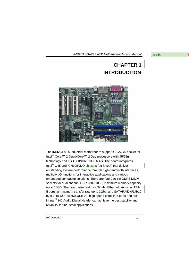
IMB203 LGA775 ATX Motherboard Userrsquos Manual
Introduction 1
CHAPTER 1 INTRODUCTION
The IMB203 ATX industrial Motherboard supports LGA775 socket for Intelreg Coretrade 2 QuadCoretrade 2 Duo processors with 4565nm technology and FSB 80010661333 MTs The board integrates Intelreg Q45 and ICH10RDO chipsets (co-layout) that deliver outstanding system performance through high-bandwidth interfaces multiple IO functions for interactive applications and various embedded computing solutions There are four 240-pin DDR3 DIMM sockets for dual channel DDR3 8001066 maximum memory capacity up to 16GB The board also features Gigabit Ethernet six serial ATA-II ports at maximum transfer rate up to 3Gbs and SATARAID 01510 by ICH10-DO Twelve USB 20 high speed compliant ports and built-in Intelreg HD Audio Digital Header can achieve the best stability and reliability for industrial applications
格式化
IMB203 LGA775 ATX Motherboard Userrsquos Manual
Introduction 2
11 Specifications CPU
Intelreg Coretrade 2 Quad Coretrade 2 Duo processors
System Chipset
Intelreg Q45 and ICH10RDO (co-layout)
CPU Socket
LGA775 Socket
Front-Side Bus
80010661333 MHz
BIOS AMI BIOS via SPI interface with socket
System Memory Four 240-pin DDR3 DIMM sockets Maximum up to 16GB DDR3 memory Supports DDR3 8001066 memory
L2 Cache Integrated in CPU
Onboard Multi-IO SPPEPPECP supported with D-Sub connector on the rear
IO Serial Ports
COM 1 9-pin D-Sub connector on the rear IO and supports RS-232422485 with jumper selectable RS-485 with auto-flow control
COM 2 25-pin 254 pitch box-header supports RS-232
COM 3 25-pin 254 pitch box-header supports RS-232
COM 4 25-pin 254 pitch box-header supports RS-232
IMB203 LGA775 ATX Motherboard Userrsquos Manual
Introduction 3
USB Interface Tweleve USB ports (four on IO bracket six ports by 2x5-pin
254 pin-header two ports for 1 USB DoM support with 2x5 254 pitch box-header)
VGA Controller
Chipset -- Intelreg integrated Graphics Gen5 on Intelreg Q45 supports 3D 2D video capabilities DX10 and OpenGL 21
Memory Size -- Intelreg DVMT supported preallocated memory for frame buffer option as 324864128256MB and 96 MB (0 + 96) 160 MB (64 + 96) 224 MB (128 + 96) 352 MB (256 + 96)
Resolution -- Analog output -- the analog port utilizes an integrated 350MHz RAMDAC that can directly drive a standard progressive scan analog monitor up to a resolution of 2048x1536 pixels with 32-bit color at 75 Hz
Analog Output Interface -- CRT from DAC output via 15-pin D-Sub connector on the edge
Ethernet
LAN1 ndash Intelreg 82567LM PHY connected to PCIe x1 port6 supports 101001000 Base-T Gigabit Ethernet RJ-45 connector on the edge with AMT Gen 5 supported with 5-pin 20 pitch wafer for LED
LAN2 -- Intelreg 82574L NIC connected to PCIe x1 port5 supports 101001000 Base-T Gigabit Ethernet RJ-45 connector on the edge with 5-pin 20 pitch wafer for LED
Serial ATA Six Serial ATA-II ports (3Gbs performance) and SATARAID
01510 by ICH10-DO
Audio HD Audio codec Realtek ALC888 for Linespeaker-out amp
MIC-in on the rear IO double deck connector with LM1877 audio amplifier
Expansion Slot 1 PCIe (x16) 4 PCI Slot (32bit33MHZ) 1 PCIe (x4) 1 PCIe (x1)(Note 1)
IMB203 LGA775 ATX Motherboard Userrsquos Manual
Introduction 4
Watchdog Timer Reset Supported (1-255 levels)
NOTE 1 CN18-PCIe (x4) and CN17-PCIe(x1) are software strap software
strap works only (x4) function or (x1) funciotn How to choose PCIe device is as follow(Defaultfunction A)
A BIOS setting (x4) function CN18 enable and CN17 disable device usage 1 x4 device (CN18-PCIe (x4)) or 1 x1 (CN18-PCIe (x4)) device can work only
B BIOS setting (x1) function CN18 enable and CN17 enable device usage 4 x1 devices (CN18) or 2 x1 devices (CN18-PCIe (x4) and CN17-PCIe(x1)) can work only
12 Utilities Supported
Intelreg Q45 Utility and Driverss VGA Drivers Ethernet Utility and Drivers RAID Utility iAMT Utility and Drivers ITPM Utility
IMB203 LGA775 ATX Motherboard Userrsquos Manual
Jumpers and Connectors 5
CHAPTER 2 JUMPERS AND CONNECTORS
21 Board Dimensions
格式化
IMB203 LGA775 ATX Motherboard Userrsquos Manual
Jumpers and Connectors 6
22 Board Layout
IMB203 LGA775 ATX Motherboard Userrsquos Manual
Jumpers and Connectors 7
23 Jumper Settings Proper jumper settings configure the IMB203 to meet your application purpose
231 COM1 Mode Select Jumpers for RS-232422485 (JP1 JP3 JP4)
These jumpers select the COM1 portrsquos communication mode to operate RS-232 or RS-422485
Description Function Jumper Setting
RS-232 (Default)
JP1
JP3
JP4
RS-422 JP1 JP3
JP4
COM1
RS-485 JP1 JP3
JP4
IMB203 LGA775 ATX Motherboard Userrsquos Manual
Jumpers and Connectors 8
232 Audio Amplifier Jumper (JP2)
Description Function Jumper Setting
Disable
Audio Amplifier
Enable (Default)
IMB203 LGA775 ATX Motherboard Userrsquos Manual
Jumpers and Connectors 9
233 CMOS Clear Jumper (JP7) You may need to use this jumper is to clear the CMOS memory if incorrect BIOS settings
Description Function Jumper Setting
Normal (Default)
CMOS Clear
Clear CMOS
234 TPM DisableEnable Jumper (JP9)
Description Function Jumper Setting
Enable TPM (Default)
TPM Disable Enable
Disabled
IMB203 LGA775 ATX Motherboard Userrsquos Manual
Jumpers and Connectors 10
235 ME DisableEnable Jumper (JP10)
Description Function Jumper Setting
Enable (Default)
ME Disable Enable
Disable
刪除
IMB203 LGA775 ATX Motherboard Userrsquos Manual
Jumpers and Connectors 11
24 Connectors Connectors connect this board with other parts of the system Loose or improper connection might cause problems Make sure all connectors are properly and firmly connected
Label Connector
CN1 VGA
CN2 COM 1
CN3 Audio out Mic in
CN4 Keyboard Mouse
CN5 Print Port
CN6 CN7 USB Ports
CN14 ATX 2x2
CN16 COM 2
CN17 PCI Express x1 Slot
CN18 PCI Express x4 Slot
CN19 COM 3
CN25 COM 4
CN26 DIO
CN27 CN29 CN33 CN45 USB
CN31 FAN
CN36 CN37 CN41 CN42 CN46 CN47
SATA
CN50 ATX-24Pin
CN52 F_PANEL
IMB203 LGA775 ATX Motherboard Userrsquos Manual
Jumpers and Connectors 12
IMB203 LGA775 ATX Motherboard Userrsquos Manual
Jumpers and Connectors 13
241 VGA Connector (CN1) The board supports CRT VGA with a 15-pin D-Sub connector for the CRT VGA display
Pin Signal Pin Signal Pin Signal 1 Red 2 Green 3 Blue 4 NA 5 GND 6 GND 7 GND 8 GND 9 VCC 10 GND 11 NA 12 DDC DATA
13 Horizontal Sync 14 Vertical Sync 15 DDC CLK
242 COM1 Connector (CN2) The board has the onboard serial port COM1 (CN2) a 9-pin D-Sub connector on the rear IO to support RS-232422485 with jumper selectable RS-485 with auto-flow control
Pin Signal 1 DCD Data carrier detect 2 RXD Receive data 3 TXD Transmit data 4 DTR Data terminal ready 5 GND ground 6 DSR Data set ready 7 RTS Request to send 8 CTS Clear to send 9 RI Ring indicator
IMB203 LGA775 ATX Motherboard Userrsquos Manual
Jumpers and Connectors 14
243 COM2~COM4 Connectors (CN16 CN19 CN25) The board has the onboard serial ports COM2~4 (CN16 CN19 CN25) three 25-pin 254 pitch box-header to support RS-232
Pin Signal Pin Signal
1 Data Carrier Detect (DCD) 2 Data Set Ready
(DSR)
3 Receive Data (RXD) 4 Request to Send
(RTS)
5 Transmit Data (TXD) 6 Clear to Send
(CTS)
7 Data Terminal Ready (DTR) 8 Ring Indicator (RI)
9 Ground (GND) 10 NC
244 Audio Connector (CN3)
Color Signal
Green LINE_OUT
Red MIC_IN
IMB203 LGA775 ATX Motherboard Userrsquos Manual
Jumpers and Connectors 15
245 PS2 KeyboardMouse Connector (CN4) The board supports a keyboard and Mouse interface
Pin Signal Pin Signal
1 KB Data 7 MS Data
2 NC 8 NC
3 GND 9 GND
4 VCC 10 VCC
5 KB CLK 11 MS CLK
6 NC 12 NC
246 Print Port Connector (CN5)
Print Port Connector This board has a multi-mode parallel port to support the following modes 1 Standard Mode
IBM PCXT PCAT and PS2trade are compatible with bi-directional parallel port
2 Enhanced Mode Enhanced parallel port (EPP) is compatible with EPP 17 and EPP 19 (IEEE 1284 compliant)
3 High Speed Mode Microsoft and Hewlett Packard extended capabilities port (ECP) is IEEE 1284 compliant
Please refer to next page for the list of pin assignment
IMB203 LGA775 ATX Motherboard Userrsquos Manual
Jumpers and Connectors 16
Print Port Pin Assignment (Default)
Pin Signal 1 Data Carrier Detect (DCD) 2 Data Set Ready (DSR)
3 Receive Data (RXD)
4 Request to Send (RTS) 5 Transmit Data (TXD)
6 Clear to Send (CTS)
7 Data Terminal Ready (DTR) 8 Ring Indicator (RI)
9 Ground (GND)
247 USB Port Connector (CN6 CN7) The Universal Serial Bus (USB) port connector on the board is for the installation of peripherals supporting the USB interface The CN6CN7 consists of two 4-pin standard USB ports
Pin Signal
1 5 USB Vcc
2 6 USB -
3 7 USB +
4 8 USB GND
IMB203 LGA775 ATX Motherboard Userrsquos Manual
Jumpers and Connectors 17
248 USB Connectors (CN27 CN29 CN33 CN45) The 10-pin standard Universal Serial Bus (USB) connectors CN27293345 on this board are for installing versatile USB interface peripherals
Pin Signal Pin Signal 1 USB 2 USB
3 USB2- 4 USB3-
5 USB2+ 6 USB3+
7 GND 8 GND
9 GND 10 GND
CN45
Pin Signal Pin Signal 1 USB 2 USB
3 USB4- 4 USB5-
5 USB4+ 6 USB5+
7 GND 8 GND
10 GND
CN27 CN29 CN33
249 ATX 4 Pin 12V In Connector (CN14) You can connect it to the ATX12V power supply for CPU Core Voltage
Pin Signal 1 GND 2 GND 3 +12V 4 +12V
IMB203 LGA775 ATX Motherboard Userrsquos Manual
Jumpers and Connectors 18
2410 Digital IO Port (DIO) Connector (CN26) The board is equipped an 8-channel digital IO connector CN26 that meets requirements for a system customary automation control The digital IO can be configured to control cash drawers sense warning signals from an Uninterrupted Power System (UPS) or perform store security control The digital IO is controlled via software programming
Pin Signal Pin Signal
1 DO1 2 DI1
3 DO2 4 DI2
5 DO3 6 DI3
7 DO4 8 DI4
9 GND 10 GND
2411 CPU Fan Connector (CN31) A CPU fan is always needed for cooling CPU heat The CPU fan connector provides power to the CPU fan
Pin Signal 1 Ground 2 +12V 3 Rotation Detection4 Speed Control
2412 SATA Connectors (CN36 CN37 CN41 CN42
CN46 CN47) These SATA connectors are for high-speed SATA interface ports and they can be connected to hard disk devices
Pin Signal
1 GND
2 SATA_TX+
3 SATA_TX-
CN364146
IMB203 LGA775 ATX Motherboard Userrsquos Manual
Jumpers and Connectors 19
4 GND
5 SATA_RX-
6 SATA_RX+
7 GND
IMB203 LGA775 ATX Motherboard Userrsquos Manual
Jumpers and Connectors 20
2413 ATX Power Connector (CN50) Steady and sufficient power can be supplied to all components on the board by connecting the power connector Please make sure all components and devices are properly installed before connecting the power connector If you use a 24-pin ATX power supply please remove the small cover from the power connector before plugging in the power cord otherwise please do not remove it Pin Signal Pin Signal 1 33V 2 33V
3 GND 4 5V
5 GND 6 5V
7 GND 8 PWR
9 5VSB 10 12V
11 12V 12 33V
13 33V 14 -12V
15 GND 16 PS_ON
17 GND 18 GND
19 GND 20 -5V
21 5V 22 5V
23 5V 24 GND
IMB203 LGA775 ATX Motherboard Userrsquos Manual
Jumpers and Connectors 21
2414 Front Panel Connector (CN52)
Power LED
This 3-pin connector denoted as Pin 1 and Pin 5 connects the system power LED indicator to such a switch on the case Pin 1 is assigned as + and Pin 5 as - The Power LED lights up when the system is powered ON Pin 3 is defined as GND
External Speaker and Internal Buzzer Connector
Pin 2 4 6 and 8 can be connected to the case-mounted speaker unit or internal buzzer While connecting the CPU card to an internal buzzer please short pins 2-4 while connecting to an external speaker you need to set pins 2-4 to Open and connect the speaker cable to pin 8 (+) and pin 2 (-)
ATX Power OnOff Button
This 2-pin connector denoted as Pin 9 and 10 connects the front panelrsquos ATX power button to the CPU card which allows users to control ATX power supply to be power onoff
System Reset Switch
Pin 11 and 12 can be connected to the case-mounted reset switch that reboots your computer instead of turning OFF the power switch It is a better way to reboot your system for a longer life of the systemrsquos power supply
HDD Activity LED
This connection is linked to hard drive activity LED on the control panel LED flashes when HDD is being accessed Pin 13 and 14 connect the hard disk drive to the front panel HDD LED Pin 13 assigned as - and Pin 14 as +
IMB203 LGA775 ATX Motherboard Userrsquos Manual
Jumpers and Connectors 22
MEMO
IMB203 LGA775 ATX Motherboard Userrsquos Manual
Hardware Installation 23
CHAPTER 3 HARDWARE INSTALLATION
Before installing the processor please access Intelreg website for more detailed information httpwwwintelcom
31 Installing the Processor The LGA775 processor socket comes with a cover to protect the processor Please install the processor into the CPU socket step by step as below
Hold the hook (A) of the lever and push it down Pull the lever (B) aside to unlock the cover
IMB203 LGA775 ATX Motherboard Userrsquos Manual
Hardware Installation 24
Remove the plastic cap (E) from the cover
Open the cover (C) you can see the contact
Be careful not to touch the contact (D)
IMB203 LGA775 ATX Motherboard Userrsquos Manual
Hardware Installation 25
Place the CPU down into the socket Be careful not to touch the contact
Hold the edges of the CPU and orientate it as the marked direction (G) down into the socket to match the (H) and (F) locations
IMB203 LGA775 ATX Motherboard Userrsquos Manual
Hardware Installation 26
Slightly push down the cover and hook the lever (I~J) The CPU is completely locked
Orientate the CPU cooling fan to fixing holes on the board
IMB203 LGA775 ATX Motherboard Userrsquos Manual
Hardware Installation 27
Screw the CPU cooling fan onto the board
Make sure the CPU fan is plugged to the CPU fan connector
IMB203 LGA775 ATX Motherboard Userrsquos Manual
Hardware Installation 28
32 Installing the Memory The board supports four 240-pin DDR3 DIMM memory sockets with maximum memory capacity up to 16GB Please follow steps below to install the memory modules 1 Push down latches on each side of the DIMM socket 2 Align the memory module with the socket that notches of
memory module must match the socket keys for a correct installation
3 Install the memory module into the socket and push it firmly down until it is fully seated The socket latches are levered upwards and clipped on to the edges of the DIMM
4 Install any remaining DIMM modules
IMB203 LGA775 ATX Motherboard Userrsquos Manual
Hardware Description 29
CHAPTER 4 HARDWARE DESCRIPTION
41 Microprocessors The IMB203 Series supports Intelreg Coretrade 2 Quad Coretrade 2 Duo processors which make your system operated under Windowsreg XP and Linux environments The system performance depends on the microprocessor Make sure all correct settings are arranged for your installed microprocessor to prevent the CPU from damages
42 BIOS The IMB203 Series uses AMI Plug and Play BIOS with a single 32Mbit SPI Flash
43 System Memory The IMB203 Series supports four 240-pin DDR3 DIMM sockets for a maximum memory of 16GB DDR3 SDRAMs The memory module can come in sizes of 1GB 2GB and 4GB
IMB203 LGA775 ATX Motherboard Userrsquos Manual
Hardware Description 30
44 IO Port Address Map The Intelreg Coretrade 2 Extreme Intelreg Coretrade 2 Quad Coretrade 2 Duo CPUs can communicate via IO ports There are total 1KB port addresses available for assignment to other devices via IO expansion cards
Address Devices 000-01F DMA controller 1
020-02D 024-025 028-029 02C-02D Interrupt controller 1
02E-02F Forwarded to LPC(LPC Super IO ) 030-031 034-035 038-039 03C-03D
Interrupt controller 2
040-043 050-053 TimerCounter (8254) 060 Forwarded to LPC (Microcontroller) 061 NMI
062-066 Forwarded to LPC (Microcontroller) 070-077 Real time clock NMI 080-091 DMA page register
092 Processor IF(Reset Generator) 093-09F DMA page register 0A0-0BF Interrupt controller 2 0C0-0DF DMA controller 2
0F0 Processor IF 0F8-0FF Math processor 170-177 Forward to SATA (SATA Controller) 1F0-1F7 Forward to SATA (SATA Controller)
376 Forward to SATA(SATA Controller) 378-37F Parallel Port (LPT) 380-38F SDLC 2 3A0-3AF SDLC 1 3B0-3BF MDA video card
(to be continued)
IMB203 LGA775 ATX Motherboard Userrsquos Manual
Hardware Description 31
Address Devices 3C0-3CF EGA card 3D0-3DF CGA card
3F6 Forward to SATA(SATA Controller) 3F8-3FF Serial port 1 (COM1) 2F8-2FF Serial port 2 (COM2)
45 Interrupt Controller (IRQ) Map The IMB203 Series is a 100 PC compatible control board It consists of 16 interrupt request lines and four out of them can be programmable The mapping list of the 16 interrupt request lines is shown as the following table
IRQ Parity check error IRQ0 System Timer Output
IRQ1 Keyboard
IRQ2 Interrupt rerouting from IRQ8 through IRQ15
IRQ3 Serial port 2
IRQ4 Serial port 1
IRQ5 PCI Device Share
IRQ7 Parallel port
IRQ8 Real time clock
IRQ9 ACPI Controller
IRQ10 PCI Device Share
IRQ11 PCI Device Share
IRQ12 PS2 Mouse
IRQ13 Math coprocessor
IRQ14 SATA Primary (Legacy Mode)
IRQ15 SATA Secondary (Legacy Mode)
IMB203 LGA775 ATX Motherboard Userrsquos Manual
Hardware Description 32
MEMO
IMB203 LGA775 ATX Motherboard Userrsquos Manual
AMI BIOS Setup Utility 33
CHAPTER 5 AMI BIOS SETUP UTILITY
This chapter provides users with detailed description how to set up basic system configuration through the AMIBIOS8 BIOS setup utility 51 Starting To enter the setup screens follow the steps below 1 Turn on the computer and press the ltDelgt key immediately 2 After you press the ltDeletegt key the main BIOS setup menu
displays You can access the other setup screens from the main BIOS setup menu such as the Chipset and Power menus
52 Navigation Keys The BIOS setuputility uses a key-based navigation system called hot keys Most of the BIOS setup utility hot keys can be used at any time during the setup navigation process These keys include ltF1gt ltF10gt ltEntergt ltESCgt ltArrowgt keys and so on
Note Some of navigation keys differ from one screen to another
IMB203 LGA775 ATX Motherboard Userrsquos Manual
AMI BIOS Setup Utility 34
LeftRight The Left ltArrowgt keys allow you to select a setup screen
UpDown The Up and Down ltArrowgt keys allow you to select a setup screen or sub-screen
+minus PlusMinus The Plus and Minus ltArrowgt keys allow you to change the field value of a particular setup item
Tab The ltTabgt key allows you to select setup fields
F1 The ltF1gt key allows you to display the General Help screen
F10 The ltF10gt key allows you to save any changes you have made and exit Setup Press the ltF10gt key to save your changes
Esc
The ltEscgt key allows you to discard any changes you have made and exit the Setup Press the ltEscgt key to exit the setup without saving your changes
Enter
The ltEntergt key allows you to display or change the setup option listed for a particular setup item The ltEntergt key can also allow you to display the setup sub- screens
IMB203 LGA775 ATX Motherboard Userrsquos Manual
AMI BIOS Setup Utility 35
53 Main Menu When you first enter the Setup Utility you will enter the Main setup screen You can always return to the Main setup screen by selecting the Main tab There are two Main Setup options They are described in this section The Main BIOS Setup screen is shown below
System TimeDate
Use this option to change the system time and date Highlight System Time or System Date using the ltArrowgt keys Enter new values through the keyboard Press the ltTabgt key or the ltArrowgt keys to move between fields The date must be entered in MMDDYY format The time is entered in HHMMSS format
IMB203 LGA775 ATX Motherboard Userrsquos Manual
AMI BIOS Setup Utility 36
54 Advanced Menu The Advanced menu allows users to set configuration of the CPU and other system devices You can select any of the items in the left frame of the screen to go to the sub menus
CPU Configuration IDE Configuration SuperIO Configuration Hardware Health Configuration ACPI Configuration AHCI Configuration Intel iAMT Configuration Intel VT-d Configuration MPS Configuration PCI Express Configuration Trusted Computing USB Configuration
For items marked with ldquo rdquo please press ltEntergt for more options
IMB203 LGA775 ATX Motherboard Userrsquos Manual
AMI BIOS Setup Utility 37
CPU Configuration This screen shows the CPU Configuration and you can change the value of the selected option
Max CPUID Value Limit
You can enable this item to let legacy operating systems boot even without support for CPUs with extended CPU ID functions
Execute-Disable Bit Capability This item helps you enable or disable the No-Execution Page Protection Technology
Core Multi-Processing This feature controls the functionality of the Core Multi-Processing to allow the processor to execute multitasking function
PECI Use this item PECI (Platform Environment Control Interface) to execute the processor temperature monitoring and management
IMB203 LGA775 ATX Motherboard Userrsquos Manual
AMI BIOS Setup Utility 38
Intel (R) C-STATE tech Use this item to enable or disable the C-State technology
IDE Configuration You can use this screen to select options for the IDE Configuration and change the value of the selected option A description of the selected item appears on the right side of the screen For items marked with ldquo rdquo please press ltEntergt for more options
SATA1 Configuration
Use this item to control the onboard SATA controller Here are the options for your selection Compatible Disabled and Enhanced
Configure SATA1 as Use this item to choose the SATA operation mode Here are the options for your selection IDE and AHCI
SATA2 Configuration Use this item to control the onboard SATA controller Here are the options for your selection Enhanced and Disabled
IMB203 LGA775 ATX Motherboard Userrsquos Manual
AMI BIOS Setup Utility 39
PrimarySecondaryThird IDE Master Select one of the hard disk drives to configure IDE devices installed in the system by pressing ltEntergt for more options
Fifth IDE Master Select one of the hard disk drives to configure IDE devices installed in the system by pressing ltEntergt for more options
IMB203 LGA775 ATX Motherboard Userrsquos Manual
AMI BIOS Setup Utility 40
SuperIO Configuration You can use this screen to select options for the SuperIO Configuration and change the value of the selected option A description of the selected item appears on the right side of the screen
Serial Port1 Address
This option specifies the base IO port address and Interrupt Request address of serial port 1 The Optimal setting is 3F8IRQ4 The Fail-Safe default setting is Disabled
Serial Port2 Address This option specifies the base IO port address and Interrupt Request address of serial port 2 The Optimal setting is 2F8IRQ3 The Fail-Safe setting is Disabled
Parallel Port Address This item allows you to determine the IO address for onboard parallel port There are several options for your selection
Parallel Port Mode
IMB203 LGA775 ATX Motherboard Userrsquos Manual
AMI BIOS Setup Utility 41
Select an operating mode for the onboard parallel (printer) port
Parallel Port IRQ Use this item to set up the IRQ for onboard parallel port
Serial Port3 Address This item specifies the base IO port address and Interrupt Request address of serial port 3 The Optimal setting is 3E8IRQ11 The Fail-Safe default setting is Disabled
Serial Port3 IRQ This item specifies the IRQ used by the serial port 3
Serial Port4 Address This item specifies the base IO port address and Interrupt Request address of serial port 4 The Optimal setting is 2E8IRQ10 The Fail-Safe default setting is Disabled
Serial Port4 IRQ This item specifies the IRQ used by the serial port 4
IMB203 LGA775 ATX Motherboard Userrsquos Manual
AMI BIOS Setup Utility 42
Hardware Health Configuration This screen shows the Hardware Health Configuration and a description of the selected item appears on the right side of the screen
HW Health Configuration
This screen displays the temperature of CPU and System Fan Speed Vcore etc
IMB203 LGA775 ATX Motherboard Userrsquos Manual
AMI BIOS Setup Utility 43
ACPI Configuration You can use this screen to select options for the ACPI Configuration and change the value of the selected option A description of the selected item appears on the right side of the screen
General ACPI Configuration
Scroll to this item and press ltEntergt to view the General ACPI Configuration sub menu which contains General ACPI (Advanced Configuration and Power Management Interface) options for your configuration
Advanced ACPI Configuration Scroll to this item and press ltEntergt to view the Advanced ACPI Configuration sub menu which contains Advanced ACPI (Advanced Configuration and Power Management Interface) options for your configuration
Chipset ACPI Configuration Scroll to this item and press ltEntergt to view the Chipset ACPI Configuration sub menu which contains Chipset ACPI (Advanced Configuration and Power Management
IMB203 LGA775 ATX Motherboard Userrsquos Manual
AMI BIOS Setup Utility 44
Interface) options for your configuration AHCI Configuration
You can use this screen to select options for the AHCI Configuration and change the value of the selected option A description of the selected item appears on the right side of the screen
AHCI BIOS Support You can enable or disable this item to control the AHCI function of the SATA controller
IMB203 LGA775 ATX Motherboard Userrsquos Manual
AMI BIOS Setup Utility 45
Intel iAMT Configuration You can use this screen to select options for the Intel iAMT Configuration and change the value of the selected option A description of the selected item appears on the right side of the screen
Intel iAMT Support
You can enable this item to support iAMT (active management technology) function to follow up the procedure for the access to AMI program screen
Unconfigure iAMTME Use this item to unconfigure the iAMTME settings
IMB203 LGA775 ATX Motherboard Userrsquos Manual
AMI BIOS Setup Utility 46
Intel VT-d Configuration You can use this screen to select options for the Intel VT-d Configuration and change the value of the selected option A description of the selected item appears on the right side of the screen
Intel VT-d Virtualization Technology for Directed IO (VT-d) extends Virtualization Technology (VT) roadmap by providing hardware assists for virtualization solution VT-d can help end users improve security and reliability of the systems and also improve performance of IO devices in virtualized environment Here are the options for your selection Disabled and Enabled
IMB203 LGA775 ATX Motherboard Userrsquos Manual
AMI BIOS Setup Utility 47
Remote Access Configuration You can use this screen to select options for the Remote Access Configuration and change the value of the selected option A description of the selected item appears on the right side of the screen
Remote Access Use this item to enable or disable the Remote Access function
IMB203 LGA775 ATX Motherboard Userrsquos Manual
AMI BIOS Setup Utility 48
PCI Express Configuration This screen shows the PCI Express Configuration and you can change its value A description of the selected item appears on the right side of the screen
Active State Power-Management
Use this item to enable or disable the function of Active State Power-Management to provide you with lower power consumption The default setting is Disabled
IMB203 LGA775 ATX Motherboard Userrsquos Manual
AMI BIOS Setup Utility 49
Trusted Computing You can use this screen to select options for the Trusted Computing and change the value of the selected option A description of the selected item appears on the right side of the screen
TCGTPM SUPPORT Use this item to control the Trusted Platform Module (TPM) function
IMB203 LGA775 ATX Motherboard Userrsquos Manual
AMI BIOS Setup Utility 50
USB Configuration You can use this screen to select options for the USB Configuration and change the value of the selected option A description of the selected item appears on the right side of the screen
USB Functions
This item allows you to enable or disable USB functions
Legacy USB Support Use this item to enable or disable support for USB device on legacy operating system The default setting is Enabled
USB 20 Controller Mode Use this item to configure the USB 20 controller The default setting is HiSpeed
BIOS EHCI Hand-Off Enabling this item provide the support for operating systems without an EHCI hand-off feature The default setting is Enabled
IMB203 LGA775 ATX Motherboard Userrsquos Manual
AMI BIOS Setup Utility 51
IMB203 LGA775 ATX Motherboard Userrsquos Manual
AMI BIOS Setup Utility 52
55 PCI PnP Menu The PCI PnP menu allows users to change the advanced settings for PCIPnP devices
Clear NVRAM
Use this item to clear the data in the NVRAM (CMOS) Here are the options for your selection No and Yes
Plug amp Play OS When the setting is No Use this item to configure all the devices in the system When the setting is Yes and if you install a Plug and Play operating system the operating system configures the Plug and Play devices not required for boot The default setting is No
IMB203 LGA775 ATX Motherboard Userrsquos Manual
AMI BIOS Setup Utility 53
PCI Latency Timer This item controls how long a PCI device can hold the PCI bus before another takes over The longer the latency the longer the PCI device can retain control of the bus before handing it over to another PCI device There are several options for your selection
Allocate IRQ to PCI VGA This item allows BIOS to choose an IRQ to assign for the PCI VGA card Here are the options for your selection No and Yes
Palette Snooping Some old graphic controllers need to ldquosnooprdquo on the VGA palette and then map it to their display as a way to provide boot information and VGA compatibility This item allows such snooping to take place Here are the options for your selection Disabled and Enabled
PCI IDE BusMaster This item is a toggle for the built-in driver that allows the onboard IDE controller to perform DMA (Direct Memory Access) transfer Here are the options for your selection Disabled and Enabled
OffBoard PCIISA IDE Card This item is for any other non-onboard PCIISA IDE controller adapter There are several options for your selection
IRQ3457910111415 These items will allow you to assign each system interrupt a type depending on the type of device using the interrupt The option ldquoAvailablerdquo means the IRQ is going to assign automatically Here are the options for your selection Available and Reserved
DMA Channel 013567 These items will allow you to assign each DMA channel a type depending on the type of device using the channel The option ldquoAvailablerdquo means the channel is going to assign automatically Here are the options for your selection Available and Reserved
IMB203 LGA775 ATX Motherboard Userrsquos Manual
AMI BIOS Setup Utility 54
56 Boot Menu The Boot menu allows users to change boot options of the system You can select any of the items in the left frame of the screen to go to the sub menus
Boot Settings Configuration Boot Device Priority Removable Drives
For items marked with ldquo rdquo please press ltEntergt for more options
IMB203 LGA775 ATX Motherboard Userrsquos Manual
AMI BIOS Setup Utility 55
Boot Settings Configuration
Quick Boot
Enabling this item lets the BIOS skip some power on self tests (POST) The default setting is Enabled
AddOn ROM Display Mode This item selects the display mode for option ROM The default setting is Force BIOS
Boot Num-Lock Use this item to select the power-on state for the NumLock The default setting is On
PS2 Mouse Support This item determines if the BIOS should reserve IRQ12 for the PS2 mouse or allow other devices to make use of this IRQ Here are the options for your selection Auto Enabled and Disabled
Wait For lsquoF1rsquo Of Error If this item is enabled the system waits for the F1 key to be pressed when error occurs The default setting is Enabled
Hit lsquoDELrsquo Message Display If this item is enabled the system displays the message
IMB203 LGA775 ATX Motherboard Userrsquos Manual
AMI BIOS Setup Utility 56
ldquoPress DEL to run Setuprdquo during POST The default setting is Enabled
Interrupt 19 Capture If this item is enabled this function makes the option ROMs to trap Interrupt 19 The default setting is Disabled
Boot Device Priority The Boot Device Priority screen specifies the boot device priority sequence from the available devices
IMB203 LGA775 ATX Motherboard Userrsquos Manual
AMI BIOS Setup Utility 57
Removable Drives Use this screen to view the removable drives in the system The BIOS will attempt to arrange the removable drive boot sequence automatically You can also change the booting sequence
IMB203 LGA775 ATX Motherboard Userrsquos Manual
AMI BIOS Setup Utility 58
57 Security Menu The Security menu allows users to change the security settings for the system
Supervisor Password
This item indicates whether a supervisor password has been set If the password has been installed Installed displays If not Not Installed displays
User Password This item indicates whether a user password has been set If the password has been installed Installed displays If not Not Installed displays
Change Supervisor Password Select this option and press ltEntergt to access the sub menu You can use the sub menu to change the supervisor password
Change User Password Select this option and press ltEntergt to access the sub menu You can use the sub menu to change the user password
IMB203 LGA775 ATX Motherboard Userrsquos Manual
AMI BIOS Setup Utility 59
58 Chipset Menu The Chipset menu allows users to change the advanced chipset settings You can select any of the items in the left frame of the screen to go to the sub menus
North Bridge Configuration South Bridge Configuration ME Subsystem Configuration
For items marked with ldquo rdquo please press ltEntergt for more options
IMB203 LGA775 ATX Motherboard Userrsquos Manual
AMI BIOS Setup Utility 60
North Bridge Configuration
Memory Remap Feature
Use this item to enable or disable the remapping of the overlapped PCI memory above the total physical memory Only 64-bit OS supports this function
DRAM Frequency This item allows you to control the Memory Clock
Configure DRAM Timing by SPD This item can enable or disable DRAM timing by SPD (Serial Presence Detect) device which is a small EEPROM chip on the memory module containing important information about the module speed size addressing mode and various parameters
Memory Hole You can reserve this area of system memory for ISA adapter ROM When this area is reserved it cannot be cached Check the user information of peripherals that need to use this area o f system memory for the memory requirements Here are the options Disabled and 15M-16M
IMB203 LGA775 ATX Motherboard Userrsquos Manual
AMI BIOS Setup Utility 61
Initiate Graphic Adapter When using multiple graphics cards this item can select which graphics controller to be the primary display device during boot
IGD Graphics Mode Select This item allows you to select the amount of system memory used by the internal graphics device
PEG Port ConfigurationPEG Port This item is a toggle to enable or disable the PCI Express port Here are the options for your selection Auto and Disabled
Video Function Configuration Press ltEntergt for the sub-menu for setting up video function
IMB203 LGA775 ATX Motherboard Userrsquos Manual
AMI BIOS Setup Utility 62
South Bridge Configuration
GbE Wake Up From S5 This item specifies whether the system will be awakened from the S5 power
HDA Controller This item allows you to enable or disable the HD audio support
Restore on AC Power Loss This item can control how the PC will behave once power is restored following a power outage or other unexpected shutdown
PCIE Port Configuration This item allows you to set or disable the PCI Express Ports
IMB203 LGA775 ATX Motherboard Userrsquos Manual
AMI BIOS Setup Utility 63
ME Subsystem Configuration
It is strongly recommended that you do not modify these options unless you are an advanced user
IMB203 LGA775 ATX Motherboard Userrsquos Manual
AMI BIOS Setup Utility 64
59 Exit Menu The Exit menu allows users to load your system configuration with optimal or failsafe default values
Save Changes and Exit
When you have completed the system configuration changes select this option to leave Setup and reboot the computer so the new system configuration parameters can take effect Select Save Changes and Exit from the Exit menu and press ltEntergt Select Ok to save changes and exit
Discard Changes and Exit Select this option to quit Setup without making any permanent changes to the system configuration Select Discard Changes and Exit from the Exit menu and press ltEntergt Select Ok to discard changes and exit
Load Optimal Defaults It automatically sets all Setup options to a complete set of default settings when you select this option The Optimal settings are designed for maximum system performance but may not work best for all computer applications In particular do not use the Optimal Setup options if your
IMB203 LGA775 ATX Motherboard Userrsquos Manual
AMI BIOS Setup Utility 65
computer is experiencing system configuration problems Select Load Optimal Defaults from the Exit menu and press ltEntergt
Load Fail-Safe Defaults It automatically sets all Setup options to a complete set of default settings when you select this option The Fail-Safe settings are designed for maximum system stability but not maximum performance Select the Fail-Safe Setup options if your computer is experiencing system configuration problems Select Load Fail-Safe Defaults from the Exit menu and press ltEntergt Select Ok to load Fail-Safe defaults
IMB203 LGA775 ATX Motherboard Userrsquos Manual
AMI BIOS Setup Utility 66
MEMO
IMB203 LGA775 ATX Motherboard Userrsquos Manual
Installation of Drivers 67
CHPATER 6 INSTALLATION OF DRIVERS
The device drivers are located on the Product Information CD-ROM that comes with the IMB203 Series package The auto-run function of drivers will guide you to install the utilities and device drivers under a Windows system You can follow the onscreen instructions to install these devices
Chipse VGA LAN Audio iAMT MEI
61 Installing Chipset Driver 1 Run the SETUPEXE program from the driver directory in
your driver CD Click ldquoNextrdquo to next step
IMB203 LGA775 ATX Motherboard Userrsquos Manual
Installation of Drivers 68
2 An Intelreg License Agreement appears to show you the important information Click ldquoYesrdquo to next step
3 Refer to the Readme file below to view the system requirements and installation information
IMB203 LGA775 ATX Motherboard Userrsquos Manual
Installation of Drivers 69
3-1 Please wait while running the following setup operations
3-2 Please wait while running the following setup operations
IMB203 LGA775 ATX Motherboard Userrsquos Manual
Installation of Drivers 70
4 Click ldquoFinishrdquo to complete the setup process
5 You will be asked to reboot your computer when the installation is completed Please click ldquoYes I want to restart my computer nowrdquo if you donrsquot need to install any other drivers Otherwise please click ldquoNo I will restart my computer laterrdquo and go on next step
IMB203 LGA775 ATX Motherboard Userrsquos Manual
Installation of Drivers 71
62 Installing VGA Driver 1 Run the SETUPEXE program from the driver directory in
your driver CD Click ldquoNextrdquo to next step
2 An Intelreg License Agreement appears to show you the
important information Click ldquoYesrdquo to next step
IMB203 LGA775 ATX Motherboard Userrsquos Manual
Installation of Drivers 72
3 The message of Readme File Information appears to show you the system requirements and installation information Please click ldquoNextrdquo
4 Please wait while running the following setup operations
When this message appears please click ldquoNextrdquo
IMB203 LGA775 ATX Motherboard Userrsquos Manual
Installation of Drivers 73
5 Click ldquoFinishrdquo to complete the setup process
6 You will be asked to reboot your computer when the installation is completed Please click ldquoYes I want to restart my computer nowrdquo if you donrsquot need to install any other drivers Otherwise please click ldquoNo I will restart my computer laterrdquo and click ldquoFinishrdquo to complete the installation
IMB203 LGA775 ATX Motherboard Userrsquos Manual
Installation of Drivers 74
63 Installing LAN Driver
11 Run the InstallShield Wizard for Network Connections from
the driver directory in your driver CD Click ldquoNextrdquo to next step
IMB203 LGA775 ATX Motherboard Userrsquos Manual
Installation of Drivers 75
12 An Intelreg License Agreement appears to show you the important information Click ldquoYesrdquo to next step
13 A Setup Options window appears that you can select the
program features you want to install
IMB203 LGA775 ATX Motherboard Userrsquos Manual
Installation of Drivers 76
2 Click ldquoInstallrdquo to start the installation
3 Please wait while running the following installation operation
IMB203 LGA775 ATX Motherboard Userrsquos Manual
Installation of Drivers 77
4 Click ldquoFinishrdquo to complete the installation
Note The Driver item [Wake on Directed Packet] default is Enabled under Windows Vista
格式化 字型 (符號) Arial
格式化 字型 (符號) Arial
格式化 字型 斜體 字型色彩 黑色 (符號) Arial 非加寬 緊縮
格式化 字型 斜體 字型色彩 黑色 (符號) Arial 非加寬 緊縮
格式化 字型 (符號) Arial 非加寬 緊縮
IMB203 LGA775 ATX Motherboard Userrsquos Manual
Installation of Drivers 78
64 Installing AUDIO Driver 1 Run the InstallShield Wizard for Realtek High Definition
Audio Driver from the driver directory in your driver CD Click ldquoNextrdquo to next step
IMB203 LGA775 ATX Motherboard Userrsquos Manual
Installation of Drivers 79
2 Click ldquoInstallrdquo to start the installation and wait while running the installation operation
3 Click ldquoFinishrdquo to complete the installation
IMB203 LGA775 ATX Motherboard Userrsquos Manual
Installation of Drivers 80
65 Installing iAMT (Active Management Technology) Driver
Note You must download and properly install the required NET version 35 provided from a separate downloading of the actual FimwareTools kit releases posted on VIP prior to loading the MEILMS Driver stack
651 LMS_SOL Setup
1 Run the setup program to install Intelreg Active Management Technology onto your computer It is strongly recommended that you exit all programs before continuing Click ldquoNextrdquo to next step
格式化 字型 (符號) Arial
格式化 字型 (符號) Arial 非加寬 緊縮
IMB203 LGA775 ATX Motherboard Userrsquos Manual
Installation of Drivers 81
2 An Intelreg license agreement appears that you need to continue the setup program by clicking ldquoYesrdquo to accept the terms
IMB203 LGA775 ATX Motherboard Userrsquos Manual
Installation of Drivers 82
3 Refer to the Readme file below to view the system requirements and installation information Click ldquoNextrdquo to next setup
4 Please wait while running the following installation operation
IMB203 LGA775 ATX Motherboard Userrsquos Manual
Installation of Drivers 83
5 Click ldquoFinishrdquo to complete the installation
IMB203 LGA775 ATX Motherboard Userrsquos Manual
Installation of Drivers 84
652 LMS_SOL_IS Setup
1 Run the setup program to install Intelreg Active Management Technology onto your computer It is strongly recommended that you exit all programs before continuing Click ldquoNextrdquo to next step
IMB203 LGA775 ATX Motherboard Userrsquos Manual
Installation of Drivers 85
2 An Intelreg license agreement appears that you need to continue the setup program by clicking ldquoYesrdquo to accept the terms
IMB203 LGA775 ATX Motherboard Userrsquos Manual
Installation of Drivers 86
3 Refer to the Readme file below to view the system requirements and installation information Click ldquoNextrdquo to next setup
4 Please wait while running the following installation operation
IMB203 LGA775 ATX Motherboard Userrsquos Manual
Installation of Drivers 87
5 Click ldquoFinishrdquo to complete the installation
IMB203 LGA775 ATX Motherboard Userrsquos Manual
Installation of Drivers 88
66 Installing MEI (Management Engine Interface) Driver
Note You must download and properly install the required NET version 35 provided from a separate downloading of the actual FimwareTools kit releases posted on VIP prior to loading the MEILMS Driver stack
1 Run the setup program to install Intelreg Management Engine
Interface onto your computer It is strongly recommended that you exit all programs before continuing Click ldquoNextrdquo to next step
格式化 字型 (符號) Arial
格式化 字型 (符號) Arial 非加寬 緊縮
IMB203 LGA775 ATX Motherboard Userrsquos Manual
Installation of Drivers 89
2 An Intelreg license agreement appears that you need to continue the setup program by clicking ldquoYesrdquo to accept the terms
IMB203 LGA775 ATX Motherboard Userrsquos Manual
Installation of Drivers 90
3 Refer to the Readme file below to view the system requirements and installation information Click ldquoNextrdquo to next setup
4 Please wait while running the following installation operation
IMB203 LGA775 ATX Motherboard Userrsquos Manual
Installation of Drivers 91
5 Click ldquoFinishrdquo to complete the installation
IMB203 LGA775 ATX Motherboard Userrsquos Manual
Installation of Drivers 92
MEMO
IMB203 LGA775 ATX Motherboard Userrsquos Manual
Watchdog Timer 93
APPENDIX A WATCHDOG TIMER
Watchdog Timer Setting After the system stops working for a while it can be auto-reset by the Watchdog Timer The integrated Watchdog Timer can be set up in the system reset mode by program
Using the Watchdog Function Start darr Un-Lock WDT O 2E 87 Un-lock super IO
O 2E 87 Un-lock super IO darr Set WDT Function O 2E 2D O 2F 20 Select Logic device O 2E 07 O 2F 08 darr Activate WDT O 2E 30
O 2F 01 Set Second or Minute O 2E F5
O 2F N N=00 or 08(See below table) darr Set base timer O 2E F6
O 2F M=000102hellipFF(Hex) Value=0 to 255 darr WDT counting
re-set timer O 2E F6
O 2F M M=000102hellipFF(See below table) darr
格式化
格式化 項目符號及編號
格式化 項目符號及編號
格式化 字型 8 點 字型色彩黑色
格式化 字型 8 點 字型色彩黑色
格式化 定位點 1257 字元左 + 不在 1012 字元 + 1386字元
格式化 字型 8 點 字型色彩黑色
格式化 定位點 1257 字元左 + 不在 134 字元 + 1362字元
格式化 字型色彩 黑色
格式化 字型色彩 黑色
刪除
IMB203 LGA775 ATX Motherboard Userrsquos Manual
Watchdog Timer 94
IF No re-set timer WDT time-out generate RESET IF to disable WDT O 2E 30
O 2F 00 Can be disable at any time
N=00
M= 00h Time-out Disable 01h Time-out occurs after 1 second 02h Time-out occurs after 2 second 03h Time-out occurs after 3 second helliphelliphelliphelliphelliphelliphelliphelliphellip FFh Time-out occurs after 255 second
N=08
M= 00h Time-out Disable 01h Time-out occurs after 1 minute 02h Time-out occurs after 2 minutes 03h Time-out occurs after 3 minutes helliphelliphelliphelliphelliphelliphelliphelliphellip
FFh Time-out occurs after 255 minutes
格式化 字型色彩 黑色
格式化 字型色彩 黑色
IMB203 LGA775 ATX Motherboard Userrsquos Manual
PCI IRQ Routing 95
APPENDIX B PCI IRQ ROUTING
PICMG PCI IRQ Routing
Device ID Slot Int
PCI Slot 0 31 0 BCDA PCI Slot 1 30 1 CDAB PCI Slot 2 29 2 DABC PCI Slot 3 28 3 ABCD
IMB203 LGA775 ATX Motherboard Userrsquos Manual
PCI IRQ Routing 96
MEMO
IMB203 LGA775 ATX Motherboard Userrsquos Manual
Configuring SATA for RAID Function 97
APPENDIX C CONFIGURING SATA FOR RAID
FUNCTION
Configuring SATA Hard Drive(s) for RAID Function (Controller IntelregICH10DODO DH only) Please follow up the steps below to configure SATA hard drive(s) (1) Install SATA hard drive(s) in your system (2) Enter the BIOS Setup to configure SATA controller mode and boot
sequence (3) Configure RAID by the RAID BIOS (4) Install the SATA controller driver during the OS installation Before you begin the SATA configuration please prepare (a) Two SATA hard drives (to ensure optimal performance it is
recommended that you use two hard drives with identical model and capacity) If you do not want to create RAID with the SATA controller you may prepare only one hard drive
(b) An empty formatted floppy disk (c) Windows XP setup disk (1) Installing SATA hard drive(s) in your system
Connect one end of the SATA signal cable to the rear of the SATA hard drive and the other end to available SATA port(s) on the board Then connect the power connector of power supply to the hard drive
(2) Configuring SATA controller mode and boot sequence by the BIOS Setup You have to make sure whether the SATA controller is configured correctly by system BIOS Setup and set up BIOS boot sequence for the SATA hard drive(s)
IMB203 LGA775 ATX Motherboard Userrsquos Manual
Configuring SATA for RAID Function 98
(2)-1-1 Turn on your system and then press the Del button to enter BIOS Setup during running POST (Power-On Self Test) If you want to create RAID just go to the Advanced Settings menuIDE configuration select the Configure SATA1 as and press ltEntergt for more options
IMB203 LGA775 ATX Motherboard Userrsquos Manual
Configuring SATA for RAID Function 99
(2)-1-2 A list of options appears please select RAID
IMB203 LGA775 ATX Motherboard Userrsquos Manual
Configuring SATA for RAID Function 100
(2)-2 Set CDROM for First Boot Device under the Boot Settings menu to boot CD-ROM after system restarts
(2)-3 Save and exit the BIOS Setup
IMB203 LGA775 ATX Motherboard Userrsquos Manual
Configuring SATA for RAID Function 101
(3) Configuring RAID by the RAID BIOS Enter the RAID BIOS setup utility to configure a RAID array Skip this step and proceed to Section 4 if you do not want to create a RAID (3)-1 After the POST memory testing and before the operating
system booting a message Press ltCtrl-Igt to enter Configuration Utility shows up accordingly press ltCTRL+ Igt to enter the RAID BIOS setup utility
(3)-2 After you press ltCTRL+ Igt the Create RAID Volume screen will appear If you want to create a RAID array select the Create RAID Volume option in the Main Menu and press ENTER
IMB203 LGA775 ATX Motherboard Userrsquos Manual
Configuring SATA for RAID Function 102
(3)-3-1 After entering the CREATE VOLUME MENU screen you can type the disk array name with 1~16 letters (letters cannot be special characters) in the item ldquoNamerdquo
(3)-3-2 When finished press ENTER to select a RAID level There are three RAID levels RAID0 RAID1 and RAID5 amp RAID10 Select a RAID level and press ENTER
IMB203 LGA775 ATX Motherboard Userrsquos Manual
Configuring SATA for RAID Function 103
(3)-4 Set the stripe block size The KB is the standard unit of stripe block size The stripe block size can be 4KB to 128KB After the setting press ENTER for the array capacity
(3)-5 After setting all the items on the menu select Create Volume
and press ENTER to start creating the RAID array
IMB203 LGA775 ATX Motherboard Userrsquos Manual
Configuring SATA for RAID Function 104
(3)-6 When prompting the confirmation press ldquoYldquo to create this volume or ldquoNldquo to cancel the creation
After the creation is completed you can see detailed information about the RAID Array in the DISKVOLUME INFORMATION section including RAID mode disk block size disk name and disk capacity etc
IMB203 LGA775 ATX Motherboard Userrsquos Manual
Configuring SATA for RAID Function 105
Delete RAID Volume If you want to delete a RAID volume select the Delete RAID Volume option in Main Menu Press ENTER and follow on-screen instructions
Please press [ESC] to exit the RAID BIOS utility Now you can proceed to install a SATA driver controller and the operating system
IMB203 LGA775 ATX Motherboard Userrsquos Manual
Configuring SATA for RAID Function 106
(4) Making a SATA Driver Disk To install the operating system onto a serial ATA hard disk successfully you need to install the SATA controller driver during the OS installation Without the driver the hard disk may not be recognized during the Windows setup process First of all please format a blank floppy disk Secondly follow up these steps below to produce a SATA driver disk Users can insert the Driver CD and the formatted blank floppy disk in another system And then please copy all of file of the f6flpy32 folder in the Driver CD to a floppy disk Note Please copy all of file of the f6flpy64 folder if installing 64-bit
Windows Operating System
IMB203 LGA775 ATX Motherboard Userrsquos Manual
Configuring SATA for RAID Function 107
(5) Installing the SATA controller driver during the OS installation Now the SATA driver disk is ready and BIOS settings configured you can proceed to install Windows 2000XP onto your SATA hard drive using the SATA driver Here is an example for Windows XP installation (5)-1 Restart your system to boot the Windows 2000XP Setup disk
and press F6 button as soon as you see the message Press F6 if you need to install a 3rd party SCSI or RAID driver After pressing the F6 button there will be a few moments for some files being loaded before next screen appears
IMB203 LGA775 ATX Motherboard Userrsquos Manual
Configuring SATA for RAID Function 108
(5)-2 When you see the screen below insert the floppy disk containing the SATA driver and press ldquoSrdquo
(5)-3 If the Setup correctly recognizes the driver of the floppy disk
a controller menu will appear below Use the ARROW keys to select Intel(R) ICH8RICH9RICH10RDO SATA RAID Controller and press ENTER Then it will begin to load the SATA driver from the floppy disk
IMB203 LGA775 ATX Motherboard Userrsquos Manual
Configuring SATA for RAID Function 109
Note If a message on the screen saying that one or some file(s) cannot be found please check the floppy disk or copy the correct SATA driver again from the driver CD
IMB203 LGA775 ATX Motherboard Userrsquos Manual
Configuring SATA for RAID Function 110
MEMO
IMB203 LGA775 ATX Motherboard Userrsquos Manual
iAMT Settings 111
APPENDIX D iAMT SETTINGS
The Intelreg Active Management Technology (Intelreg iAMT) has decreased a major barrier to IT efficiency that uses built-in platform capabilities and popular third-party management and security applications to allow IT a better discovering healing and protection their networked computing assets In order to utilize Intel iAMT you must enter the ME BIOS (CTRL + P during system startup) change the ME BIOS password and then select ldquoIntelreg iAMTrdquo as the manageability feature
D1 Entering MEBx 1 You must go to BIOS TO start iAMT function 2 Exit from BIOS after starting iAMT and press Ctrl+P to enter MEBx Setting
It is better to press Ctrl+P before the screen popping out
格式化
IMB203 LGA775 ATX Motherboard Userrsquos Manual
iAMT Settings 112
D2 Set amp Change Password 1 You will be asked to set a password when first log in The default
password is lsquoadminrsquo
2 You will be asked to change the password before setting ME
Change Password
IMB203 LGA775 ATX Motherboard Userrsquos Manual
iAMT Settings 113
3 You must confirm your new password while revising (as Remark 1)
Remark 1 The new password must contain (example 11qqQQ) (default value)
Eight characters
One upper case
One lower case
One number
One special symbol such as $ or
( excepted)
Underline ( _ ) and space are valid characters for password but they wonrsquot make higher complexity
IMB203 LGA775 ATX Motherboard Userrsquos Manual
iAMT Settings 114
D3 Intelreg iAMT Settings 1 Select Intelreg iAMT Configuration and press ltENTERgt
2 Key in the Host Name If Intelreg iAMT set to lsquoDHCPlsquo the Host name must be identical to the operating system mechanic
IMB203 LGA775 ATX Motherboard Userrsquos Manual
iAMT Settings 115
3 Select TCPIP to get into Network interface and set it to lsquoENABLEDrsquo into DHCP Mode and set it to lsquoDISABLEDrsquo (as Remark 2) into Domain name and set the Intel Management Engine domain name such as lsquoAMTintelcomrsquo
(3-1)
(3-2)
IMB203 LGA775 ATX Motherboard Userrsquos Manual
iAMT Settings 116
Remark 2 DHCP Mode lsquoDISABLEDlsquo if DHCP Mode is disabled you can make the following settings
IP address
Subnet mask
IMB203 LGA775 ATX Motherboard Userrsquos Manual
iAMT Settings 117
Default Gateway address
Preferred DNS address
IMB203 LGA775 ATX Motherboard Userrsquos Manual
iAMT Settings 118
Alternate DNS address
Domain name
4 Exit from MEBx after completing the iAMT settings
IMB203 LGA775 ATX Motherboard Userrsquos Manual
iAMT Settings 119
D4 iAMT Web Console 1 From a web browser please type http(IP ADDRESS)16992
which connects to iAMT Web Example http1014021416992
2 To log on you will be required to type in username and password
for access to the Web
USER admin (default value)
PASS (MEBx password)
IMB203 LGA775 ATX Motherboard Userrsquos Manual
iAMT Settings 120
3 Enter the iAMT Web
4 Click Remote Control and select commands on the right side
IMB203 LGA775 ATX Motherboard Userrsquos Manual
iAMT Settings 121
5 When you have finished using the iAMT Web console close the Web browser
IMB203 LGA775 ATX Motherboard Userrsquos Manual
iAMT Settings 122
MEMO
IMB203 LGA775 ATX Motherboard Userrsquos Manual
Introduction 2
11 Specifications CPU
Intelreg Coretrade 2 Quad Coretrade 2 Duo processors
System Chipset
Intelreg Q45 and ICH10RDO (co-layout)
CPU Socket
LGA775 Socket
Front-Side Bus
80010661333 MHz
BIOS AMI BIOS via SPI interface with socket
System Memory Four 240-pin DDR3 DIMM sockets Maximum up to 16GB DDR3 memory Supports DDR3 8001066 memory
L2 Cache Integrated in CPU
Onboard Multi-IO SPPEPPECP supported with D-Sub connector on the rear
IO Serial Ports
COM 1 9-pin D-Sub connector on the rear IO and supports RS-232422485 with jumper selectable RS-485 with auto-flow control
COM 2 25-pin 254 pitch box-header supports RS-232
COM 3 25-pin 254 pitch box-header supports RS-232
COM 4 25-pin 254 pitch box-header supports RS-232
IMB203 LGA775 ATX Motherboard Userrsquos Manual
Introduction 3
USB Interface Tweleve USB ports (four on IO bracket six ports by 2x5-pin
254 pin-header two ports for 1 USB DoM support with 2x5 254 pitch box-header)
VGA Controller
Chipset -- Intelreg integrated Graphics Gen5 on Intelreg Q45 supports 3D 2D video capabilities DX10 and OpenGL 21
Memory Size -- Intelreg DVMT supported preallocated memory for frame buffer option as 324864128256MB and 96 MB (0 + 96) 160 MB (64 + 96) 224 MB (128 + 96) 352 MB (256 + 96)
Resolution -- Analog output -- the analog port utilizes an integrated 350MHz RAMDAC that can directly drive a standard progressive scan analog monitor up to a resolution of 2048x1536 pixels with 32-bit color at 75 Hz
Analog Output Interface -- CRT from DAC output via 15-pin D-Sub connector on the edge
Ethernet
LAN1 ndash Intelreg 82567LM PHY connected to PCIe x1 port6 supports 101001000 Base-T Gigabit Ethernet RJ-45 connector on the edge with AMT Gen 5 supported with 5-pin 20 pitch wafer for LED
LAN2 -- Intelreg 82574L NIC connected to PCIe x1 port5 supports 101001000 Base-T Gigabit Ethernet RJ-45 connector on the edge with 5-pin 20 pitch wafer for LED
Serial ATA Six Serial ATA-II ports (3Gbs performance) and SATARAID
01510 by ICH10-DO
Audio HD Audio codec Realtek ALC888 for Linespeaker-out amp
MIC-in on the rear IO double deck connector with LM1877 audio amplifier
Expansion Slot 1 PCIe (x16) 4 PCI Slot (32bit33MHZ) 1 PCIe (x4) 1 PCIe (x1)(Note 1)
IMB203 LGA775 ATX Motherboard Userrsquos Manual
Introduction 4
Watchdog Timer Reset Supported (1-255 levels)
NOTE 1 CN18-PCIe (x4) and CN17-PCIe(x1) are software strap software
strap works only (x4) function or (x1) funciotn How to choose PCIe device is as follow(Defaultfunction A)
A BIOS setting (x4) function CN18 enable and CN17 disable device usage 1 x4 device (CN18-PCIe (x4)) or 1 x1 (CN18-PCIe (x4)) device can work only
B BIOS setting (x1) function CN18 enable and CN17 enable device usage 4 x1 devices (CN18) or 2 x1 devices (CN18-PCIe (x4) and CN17-PCIe(x1)) can work only
12 Utilities Supported
Intelreg Q45 Utility and Driverss VGA Drivers Ethernet Utility and Drivers RAID Utility iAMT Utility and Drivers ITPM Utility
IMB203 LGA775 ATX Motherboard Userrsquos Manual
Jumpers and Connectors 5
CHAPTER 2 JUMPERS AND CONNECTORS
21 Board Dimensions
格式化
IMB203 LGA775 ATX Motherboard Userrsquos Manual
Jumpers and Connectors 6
22 Board Layout
IMB203 LGA775 ATX Motherboard Userrsquos Manual
Jumpers and Connectors 7
23 Jumper Settings Proper jumper settings configure the IMB203 to meet your application purpose
231 COM1 Mode Select Jumpers for RS-232422485 (JP1 JP3 JP4)
These jumpers select the COM1 portrsquos communication mode to operate RS-232 or RS-422485
Description Function Jumper Setting
RS-232 (Default)
JP1
JP3
JP4
RS-422 JP1 JP3
JP4
COM1
RS-485 JP1 JP3
JP4
IMB203 LGA775 ATX Motherboard Userrsquos Manual
Jumpers and Connectors 8
232 Audio Amplifier Jumper (JP2)
Description Function Jumper Setting
Disable
Audio Amplifier
Enable (Default)
IMB203 LGA775 ATX Motherboard Userrsquos Manual
Jumpers and Connectors 9
233 CMOS Clear Jumper (JP7) You may need to use this jumper is to clear the CMOS memory if incorrect BIOS settings
Description Function Jumper Setting
Normal (Default)
CMOS Clear
Clear CMOS
234 TPM DisableEnable Jumper (JP9)
Description Function Jumper Setting
Enable TPM (Default)
TPM Disable Enable
Disabled
IMB203 LGA775 ATX Motherboard Userrsquos Manual
Jumpers and Connectors 10
235 ME DisableEnable Jumper (JP10)
Description Function Jumper Setting
Enable (Default)
ME Disable Enable
Disable
刪除
IMB203 LGA775 ATX Motherboard Userrsquos Manual
Jumpers and Connectors 11
24 Connectors Connectors connect this board with other parts of the system Loose or improper connection might cause problems Make sure all connectors are properly and firmly connected
Label Connector
CN1 VGA
CN2 COM 1
CN3 Audio out Mic in
CN4 Keyboard Mouse
CN5 Print Port
CN6 CN7 USB Ports
CN14 ATX 2x2
CN16 COM 2
CN17 PCI Express x1 Slot
CN18 PCI Express x4 Slot
CN19 COM 3
CN25 COM 4
CN26 DIO
CN27 CN29 CN33 CN45 USB
CN31 FAN
CN36 CN37 CN41 CN42 CN46 CN47
SATA
CN50 ATX-24Pin
CN52 F_PANEL
IMB203 LGA775 ATX Motherboard Userrsquos Manual
Jumpers and Connectors 12
IMB203 LGA775 ATX Motherboard Userrsquos Manual
Jumpers and Connectors 13
241 VGA Connector (CN1) The board supports CRT VGA with a 15-pin D-Sub connector for the CRT VGA display
Pin Signal Pin Signal Pin Signal 1 Red 2 Green 3 Blue 4 NA 5 GND 6 GND 7 GND 8 GND 9 VCC 10 GND 11 NA 12 DDC DATA
13 Horizontal Sync 14 Vertical Sync 15 DDC CLK
242 COM1 Connector (CN2) The board has the onboard serial port COM1 (CN2) a 9-pin D-Sub connector on the rear IO to support RS-232422485 with jumper selectable RS-485 with auto-flow control
Pin Signal 1 DCD Data carrier detect 2 RXD Receive data 3 TXD Transmit data 4 DTR Data terminal ready 5 GND ground 6 DSR Data set ready 7 RTS Request to send 8 CTS Clear to send 9 RI Ring indicator
IMB203 LGA775 ATX Motherboard Userrsquos Manual
Jumpers and Connectors 14
243 COM2~COM4 Connectors (CN16 CN19 CN25) The board has the onboard serial ports COM2~4 (CN16 CN19 CN25) three 25-pin 254 pitch box-header to support RS-232
Pin Signal Pin Signal
1 Data Carrier Detect (DCD) 2 Data Set Ready
(DSR)
3 Receive Data (RXD) 4 Request to Send
(RTS)
5 Transmit Data (TXD) 6 Clear to Send
(CTS)
7 Data Terminal Ready (DTR) 8 Ring Indicator (RI)
9 Ground (GND) 10 NC
244 Audio Connector (CN3)
Color Signal
Green LINE_OUT
Red MIC_IN
IMB203 LGA775 ATX Motherboard Userrsquos Manual
Jumpers and Connectors 15
245 PS2 KeyboardMouse Connector (CN4) The board supports a keyboard and Mouse interface
Pin Signal Pin Signal
1 KB Data 7 MS Data
2 NC 8 NC
3 GND 9 GND
4 VCC 10 VCC
5 KB CLK 11 MS CLK
6 NC 12 NC
246 Print Port Connector (CN5)
Print Port Connector This board has a multi-mode parallel port to support the following modes 1 Standard Mode
IBM PCXT PCAT and PS2trade are compatible with bi-directional parallel port
2 Enhanced Mode Enhanced parallel port (EPP) is compatible with EPP 17 and EPP 19 (IEEE 1284 compliant)
3 High Speed Mode Microsoft and Hewlett Packard extended capabilities port (ECP) is IEEE 1284 compliant
Please refer to next page for the list of pin assignment
IMB203 LGA775 ATX Motherboard Userrsquos Manual
Jumpers and Connectors 16
Print Port Pin Assignment (Default)
Pin Signal 1 Data Carrier Detect (DCD) 2 Data Set Ready (DSR)
3 Receive Data (RXD)
4 Request to Send (RTS) 5 Transmit Data (TXD)
6 Clear to Send (CTS)
7 Data Terminal Ready (DTR) 8 Ring Indicator (RI)
9 Ground (GND)
247 USB Port Connector (CN6 CN7) The Universal Serial Bus (USB) port connector on the board is for the installation of peripherals supporting the USB interface The CN6CN7 consists of two 4-pin standard USB ports
Pin Signal
1 5 USB Vcc
2 6 USB -
3 7 USB +
4 8 USB GND
IMB203 LGA775 ATX Motherboard Userrsquos Manual
Jumpers and Connectors 17
248 USB Connectors (CN27 CN29 CN33 CN45) The 10-pin standard Universal Serial Bus (USB) connectors CN27293345 on this board are for installing versatile USB interface peripherals
Pin Signal Pin Signal 1 USB 2 USB
3 USB2- 4 USB3-
5 USB2+ 6 USB3+
7 GND 8 GND
9 GND 10 GND
CN45
Pin Signal Pin Signal 1 USB 2 USB
3 USB4- 4 USB5-
5 USB4+ 6 USB5+
7 GND 8 GND
10 GND
CN27 CN29 CN33
249 ATX 4 Pin 12V In Connector (CN14) You can connect it to the ATX12V power supply for CPU Core Voltage
Pin Signal 1 GND 2 GND 3 +12V 4 +12V
IMB203 LGA775 ATX Motherboard Userrsquos Manual
Jumpers and Connectors 18
2410 Digital IO Port (DIO) Connector (CN26) The board is equipped an 8-channel digital IO connector CN26 that meets requirements for a system customary automation control The digital IO can be configured to control cash drawers sense warning signals from an Uninterrupted Power System (UPS) or perform store security control The digital IO is controlled via software programming
Pin Signal Pin Signal
1 DO1 2 DI1
3 DO2 4 DI2
5 DO3 6 DI3
7 DO4 8 DI4
9 GND 10 GND
2411 CPU Fan Connector (CN31) A CPU fan is always needed for cooling CPU heat The CPU fan connector provides power to the CPU fan
Pin Signal 1 Ground 2 +12V 3 Rotation Detection4 Speed Control
2412 SATA Connectors (CN36 CN37 CN41 CN42
CN46 CN47) These SATA connectors are for high-speed SATA interface ports and they can be connected to hard disk devices
Pin Signal
1 GND
2 SATA_TX+
3 SATA_TX-
CN364146
IMB203 LGA775 ATX Motherboard Userrsquos Manual
Jumpers and Connectors 19
4 GND
5 SATA_RX-
6 SATA_RX+
7 GND
IMB203 LGA775 ATX Motherboard Userrsquos Manual
Jumpers and Connectors 20
2413 ATX Power Connector (CN50) Steady and sufficient power can be supplied to all components on the board by connecting the power connector Please make sure all components and devices are properly installed before connecting the power connector If you use a 24-pin ATX power supply please remove the small cover from the power connector before plugging in the power cord otherwise please do not remove it Pin Signal Pin Signal 1 33V 2 33V
3 GND 4 5V
5 GND 6 5V
7 GND 8 PWR
9 5VSB 10 12V
11 12V 12 33V
13 33V 14 -12V
15 GND 16 PS_ON
17 GND 18 GND
19 GND 20 -5V
21 5V 22 5V
23 5V 24 GND
IMB203 LGA775 ATX Motherboard Userrsquos Manual
Jumpers and Connectors 21
2414 Front Panel Connector (CN52)
Power LED
This 3-pin connector denoted as Pin 1 and Pin 5 connects the system power LED indicator to such a switch on the case Pin 1 is assigned as + and Pin 5 as - The Power LED lights up when the system is powered ON Pin 3 is defined as GND
External Speaker and Internal Buzzer Connector
Pin 2 4 6 and 8 can be connected to the case-mounted speaker unit or internal buzzer While connecting the CPU card to an internal buzzer please short pins 2-4 while connecting to an external speaker you need to set pins 2-4 to Open and connect the speaker cable to pin 8 (+) and pin 2 (-)
ATX Power OnOff Button
This 2-pin connector denoted as Pin 9 and 10 connects the front panelrsquos ATX power button to the CPU card which allows users to control ATX power supply to be power onoff
System Reset Switch
Pin 11 and 12 can be connected to the case-mounted reset switch that reboots your computer instead of turning OFF the power switch It is a better way to reboot your system for a longer life of the systemrsquos power supply
HDD Activity LED
This connection is linked to hard drive activity LED on the control panel LED flashes when HDD is being accessed Pin 13 and 14 connect the hard disk drive to the front panel HDD LED Pin 13 assigned as - and Pin 14 as +
IMB203 LGA775 ATX Motherboard Userrsquos Manual
Jumpers and Connectors 22
MEMO
IMB203 LGA775 ATX Motherboard Userrsquos Manual
Hardware Installation 23
CHAPTER 3 HARDWARE INSTALLATION
Before installing the processor please access Intelreg website for more detailed information httpwwwintelcom
31 Installing the Processor The LGA775 processor socket comes with a cover to protect the processor Please install the processor into the CPU socket step by step as below
Hold the hook (A) of the lever and push it down Pull the lever (B) aside to unlock the cover
IMB203 LGA775 ATX Motherboard Userrsquos Manual
Hardware Installation 24
Remove the plastic cap (E) from the cover
Open the cover (C) you can see the contact
Be careful not to touch the contact (D)
IMB203 LGA775 ATX Motherboard Userrsquos Manual
Hardware Installation 25
Place the CPU down into the socket Be careful not to touch the contact
Hold the edges of the CPU and orientate it as the marked direction (G) down into the socket to match the (H) and (F) locations
IMB203 LGA775 ATX Motherboard Userrsquos Manual
Hardware Installation 26
Slightly push down the cover and hook the lever (I~J) The CPU is completely locked
Orientate the CPU cooling fan to fixing holes on the board
IMB203 LGA775 ATX Motherboard Userrsquos Manual
Hardware Installation 27
Screw the CPU cooling fan onto the board
Make sure the CPU fan is plugged to the CPU fan connector
IMB203 LGA775 ATX Motherboard Userrsquos Manual
Hardware Installation 28
32 Installing the Memory The board supports four 240-pin DDR3 DIMM memory sockets with maximum memory capacity up to 16GB Please follow steps below to install the memory modules 1 Push down latches on each side of the DIMM socket 2 Align the memory module with the socket that notches of
memory module must match the socket keys for a correct installation
3 Install the memory module into the socket and push it firmly down until it is fully seated The socket latches are levered upwards and clipped on to the edges of the DIMM
4 Install any remaining DIMM modules
IMB203 LGA775 ATX Motherboard Userrsquos Manual
Hardware Description 29
CHAPTER 4 HARDWARE DESCRIPTION
41 Microprocessors The IMB203 Series supports Intelreg Coretrade 2 Quad Coretrade 2 Duo processors which make your system operated under Windowsreg XP and Linux environments The system performance depends on the microprocessor Make sure all correct settings are arranged for your installed microprocessor to prevent the CPU from damages
42 BIOS The IMB203 Series uses AMI Plug and Play BIOS with a single 32Mbit SPI Flash
43 System Memory The IMB203 Series supports four 240-pin DDR3 DIMM sockets for a maximum memory of 16GB DDR3 SDRAMs The memory module can come in sizes of 1GB 2GB and 4GB
IMB203 LGA775 ATX Motherboard Userrsquos Manual
Hardware Description 30
44 IO Port Address Map The Intelreg Coretrade 2 Extreme Intelreg Coretrade 2 Quad Coretrade 2 Duo CPUs can communicate via IO ports There are total 1KB port addresses available for assignment to other devices via IO expansion cards
Address Devices 000-01F DMA controller 1
020-02D 024-025 028-029 02C-02D Interrupt controller 1
02E-02F Forwarded to LPC(LPC Super IO ) 030-031 034-035 038-039 03C-03D
Interrupt controller 2
040-043 050-053 TimerCounter (8254) 060 Forwarded to LPC (Microcontroller) 061 NMI
062-066 Forwarded to LPC (Microcontroller) 070-077 Real time clock NMI 080-091 DMA page register
092 Processor IF(Reset Generator) 093-09F DMA page register 0A0-0BF Interrupt controller 2 0C0-0DF DMA controller 2
0F0 Processor IF 0F8-0FF Math processor 170-177 Forward to SATA (SATA Controller) 1F0-1F7 Forward to SATA (SATA Controller)
376 Forward to SATA(SATA Controller) 378-37F Parallel Port (LPT) 380-38F SDLC 2 3A0-3AF SDLC 1 3B0-3BF MDA video card
(to be continued)
IMB203 LGA775 ATX Motherboard Userrsquos Manual
Hardware Description 31
Address Devices 3C0-3CF EGA card 3D0-3DF CGA card
3F6 Forward to SATA(SATA Controller) 3F8-3FF Serial port 1 (COM1) 2F8-2FF Serial port 2 (COM2)
45 Interrupt Controller (IRQ) Map The IMB203 Series is a 100 PC compatible control board It consists of 16 interrupt request lines and four out of them can be programmable The mapping list of the 16 interrupt request lines is shown as the following table
IRQ Parity check error IRQ0 System Timer Output
IRQ1 Keyboard
IRQ2 Interrupt rerouting from IRQ8 through IRQ15
IRQ3 Serial port 2
IRQ4 Serial port 1
IRQ5 PCI Device Share
IRQ7 Parallel port
IRQ8 Real time clock
IRQ9 ACPI Controller
IRQ10 PCI Device Share
IRQ11 PCI Device Share
IRQ12 PS2 Mouse
IRQ13 Math coprocessor
IRQ14 SATA Primary (Legacy Mode)
IRQ15 SATA Secondary (Legacy Mode)
IMB203 LGA775 ATX Motherboard Userrsquos Manual
Hardware Description 32
MEMO
IMB203 LGA775 ATX Motherboard Userrsquos Manual
AMI BIOS Setup Utility 33
CHAPTER 5 AMI BIOS SETUP UTILITY
This chapter provides users with detailed description how to set up basic system configuration through the AMIBIOS8 BIOS setup utility 51 Starting To enter the setup screens follow the steps below 1 Turn on the computer and press the ltDelgt key immediately 2 After you press the ltDeletegt key the main BIOS setup menu
displays You can access the other setup screens from the main BIOS setup menu such as the Chipset and Power menus
52 Navigation Keys The BIOS setuputility uses a key-based navigation system called hot keys Most of the BIOS setup utility hot keys can be used at any time during the setup navigation process These keys include ltF1gt ltF10gt ltEntergt ltESCgt ltArrowgt keys and so on
Note Some of navigation keys differ from one screen to another
IMB203 LGA775 ATX Motherboard Userrsquos Manual
AMI BIOS Setup Utility 34
LeftRight The Left ltArrowgt keys allow you to select a setup screen
UpDown The Up and Down ltArrowgt keys allow you to select a setup screen or sub-screen
+minus PlusMinus The Plus and Minus ltArrowgt keys allow you to change the field value of a particular setup item
Tab The ltTabgt key allows you to select setup fields
F1 The ltF1gt key allows you to display the General Help screen
F10 The ltF10gt key allows you to save any changes you have made and exit Setup Press the ltF10gt key to save your changes
Esc
The ltEscgt key allows you to discard any changes you have made and exit the Setup Press the ltEscgt key to exit the setup without saving your changes
Enter
The ltEntergt key allows you to display or change the setup option listed for a particular setup item The ltEntergt key can also allow you to display the setup sub- screens
IMB203 LGA775 ATX Motherboard Userrsquos Manual
AMI BIOS Setup Utility 35
53 Main Menu When you first enter the Setup Utility you will enter the Main setup screen You can always return to the Main setup screen by selecting the Main tab There are two Main Setup options They are described in this section The Main BIOS Setup screen is shown below
System TimeDate
Use this option to change the system time and date Highlight System Time or System Date using the ltArrowgt keys Enter new values through the keyboard Press the ltTabgt key or the ltArrowgt keys to move between fields The date must be entered in MMDDYY format The time is entered in HHMMSS format
IMB203 LGA775 ATX Motherboard Userrsquos Manual
AMI BIOS Setup Utility 36
54 Advanced Menu The Advanced menu allows users to set configuration of the CPU and other system devices You can select any of the items in the left frame of the screen to go to the sub menus
CPU Configuration IDE Configuration SuperIO Configuration Hardware Health Configuration ACPI Configuration AHCI Configuration Intel iAMT Configuration Intel VT-d Configuration MPS Configuration PCI Express Configuration Trusted Computing USB Configuration
For items marked with ldquo rdquo please press ltEntergt for more options
IMB203 LGA775 ATX Motherboard Userrsquos Manual
AMI BIOS Setup Utility 37
CPU Configuration This screen shows the CPU Configuration and you can change the value of the selected option
Max CPUID Value Limit
You can enable this item to let legacy operating systems boot even without support for CPUs with extended CPU ID functions
Execute-Disable Bit Capability This item helps you enable or disable the No-Execution Page Protection Technology
Core Multi-Processing This feature controls the functionality of the Core Multi-Processing to allow the processor to execute multitasking function
PECI Use this item PECI (Platform Environment Control Interface) to execute the processor temperature monitoring and management
IMB203 LGA775 ATX Motherboard Userrsquos Manual
AMI BIOS Setup Utility 38
Intel (R) C-STATE tech Use this item to enable or disable the C-State technology
IDE Configuration You can use this screen to select options for the IDE Configuration and change the value of the selected option A description of the selected item appears on the right side of the screen For items marked with ldquo rdquo please press ltEntergt for more options
SATA1 Configuration
Use this item to control the onboard SATA controller Here are the options for your selection Compatible Disabled and Enhanced
Configure SATA1 as Use this item to choose the SATA operation mode Here are the options for your selection IDE and AHCI
SATA2 Configuration Use this item to control the onboard SATA controller Here are the options for your selection Enhanced and Disabled
IMB203 LGA775 ATX Motherboard Userrsquos Manual
AMI BIOS Setup Utility 39
PrimarySecondaryThird IDE Master Select one of the hard disk drives to configure IDE devices installed in the system by pressing ltEntergt for more options
Fifth IDE Master Select one of the hard disk drives to configure IDE devices installed in the system by pressing ltEntergt for more options
IMB203 LGA775 ATX Motherboard Userrsquos Manual
AMI BIOS Setup Utility 40
SuperIO Configuration You can use this screen to select options for the SuperIO Configuration and change the value of the selected option A description of the selected item appears on the right side of the screen
Serial Port1 Address
This option specifies the base IO port address and Interrupt Request address of serial port 1 The Optimal setting is 3F8IRQ4 The Fail-Safe default setting is Disabled
Serial Port2 Address This option specifies the base IO port address and Interrupt Request address of serial port 2 The Optimal setting is 2F8IRQ3 The Fail-Safe setting is Disabled
Parallel Port Address This item allows you to determine the IO address for onboard parallel port There are several options for your selection
Parallel Port Mode
IMB203 LGA775 ATX Motherboard Userrsquos Manual
AMI BIOS Setup Utility 41
Select an operating mode for the onboard parallel (printer) port
Parallel Port IRQ Use this item to set up the IRQ for onboard parallel port
Serial Port3 Address This item specifies the base IO port address and Interrupt Request address of serial port 3 The Optimal setting is 3E8IRQ11 The Fail-Safe default setting is Disabled
Serial Port3 IRQ This item specifies the IRQ used by the serial port 3
Serial Port4 Address This item specifies the base IO port address and Interrupt Request address of serial port 4 The Optimal setting is 2E8IRQ10 The Fail-Safe default setting is Disabled
Serial Port4 IRQ This item specifies the IRQ used by the serial port 4
IMB203 LGA775 ATX Motherboard Userrsquos Manual
AMI BIOS Setup Utility 42
Hardware Health Configuration This screen shows the Hardware Health Configuration and a description of the selected item appears on the right side of the screen
HW Health Configuration
This screen displays the temperature of CPU and System Fan Speed Vcore etc
IMB203 LGA775 ATX Motherboard Userrsquos Manual
AMI BIOS Setup Utility 43
ACPI Configuration You can use this screen to select options for the ACPI Configuration and change the value of the selected option A description of the selected item appears on the right side of the screen
General ACPI Configuration
Scroll to this item and press ltEntergt to view the General ACPI Configuration sub menu which contains General ACPI (Advanced Configuration and Power Management Interface) options for your configuration
Advanced ACPI Configuration Scroll to this item and press ltEntergt to view the Advanced ACPI Configuration sub menu which contains Advanced ACPI (Advanced Configuration and Power Management Interface) options for your configuration
Chipset ACPI Configuration Scroll to this item and press ltEntergt to view the Chipset ACPI Configuration sub menu which contains Chipset ACPI (Advanced Configuration and Power Management
IMB203 LGA775 ATX Motherboard Userrsquos Manual
AMI BIOS Setup Utility 44
Interface) options for your configuration AHCI Configuration
You can use this screen to select options for the AHCI Configuration and change the value of the selected option A description of the selected item appears on the right side of the screen
AHCI BIOS Support You can enable or disable this item to control the AHCI function of the SATA controller
IMB203 LGA775 ATX Motherboard Userrsquos Manual
AMI BIOS Setup Utility 45
Intel iAMT Configuration You can use this screen to select options for the Intel iAMT Configuration and change the value of the selected option A description of the selected item appears on the right side of the screen
Intel iAMT Support
You can enable this item to support iAMT (active management technology) function to follow up the procedure for the access to AMI program screen
Unconfigure iAMTME Use this item to unconfigure the iAMTME settings
IMB203 LGA775 ATX Motherboard Userrsquos Manual
AMI BIOS Setup Utility 46
Intel VT-d Configuration You can use this screen to select options for the Intel VT-d Configuration and change the value of the selected option A description of the selected item appears on the right side of the screen
Intel VT-d Virtualization Technology for Directed IO (VT-d) extends Virtualization Technology (VT) roadmap by providing hardware assists for virtualization solution VT-d can help end users improve security and reliability of the systems and also improve performance of IO devices in virtualized environment Here are the options for your selection Disabled and Enabled
IMB203 LGA775 ATX Motherboard Userrsquos Manual
AMI BIOS Setup Utility 47
Remote Access Configuration You can use this screen to select options for the Remote Access Configuration and change the value of the selected option A description of the selected item appears on the right side of the screen
Remote Access Use this item to enable or disable the Remote Access function
IMB203 LGA775 ATX Motherboard Userrsquos Manual
AMI BIOS Setup Utility 48
PCI Express Configuration This screen shows the PCI Express Configuration and you can change its value A description of the selected item appears on the right side of the screen
Active State Power-Management
Use this item to enable or disable the function of Active State Power-Management to provide you with lower power consumption The default setting is Disabled
IMB203 LGA775 ATX Motherboard Userrsquos Manual
AMI BIOS Setup Utility 49
Trusted Computing You can use this screen to select options for the Trusted Computing and change the value of the selected option A description of the selected item appears on the right side of the screen
TCGTPM SUPPORT Use this item to control the Trusted Platform Module (TPM) function
IMB203 LGA775 ATX Motherboard Userrsquos Manual
AMI BIOS Setup Utility 50
USB Configuration You can use this screen to select options for the USB Configuration and change the value of the selected option A description of the selected item appears on the right side of the screen
USB Functions
This item allows you to enable or disable USB functions
Legacy USB Support Use this item to enable or disable support for USB device on legacy operating system The default setting is Enabled
USB 20 Controller Mode Use this item to configure the USB 20 controller The default setting is HiSpeed
BIOS EHCI Hand-Off Enabling this item provide the support for operating systems without an EHCI hand-off feature The default setting is Enabled
IMB203 LGA775 ATX Motherboard Userrsquos Manual
AMI BIOS Setup Utility 51
IMB203 LGA775 ATX Motherboard Userrsquos Manual
AMI BIOS Setup Utility 52
55 PCI PnP Menu The PCI PnP menu allows users to change the advanced settings for PCIPnP devices
Clear NVRAM
Use this item to clear the data in the NVRAM (CMOS) Here are the options for your selection No and Yes
Plug amp Play OS When the setting is No Use this item to configure all the devices in the system When the setting is Yes and if you install a Plug and Play operating system the operating system configures the Plug and Play devices not required for boot The default setting is No
IMB203 LGA775 ATX Motherboard Userrsquos Manual
AMI BIOS Setup Utility 53
PCI Latency Timer This item controls how long a PCI device can hold the PCI bus before another takes over The longer the latency the longer the PCI device can retain control of the bus before handing it over to another PCI device There are several options for your selection
Allocate IRQ to PCI VGA This item allows BIOS to choose an IRQ to assign for the PCI VGA card Here are the options for your selection No and Yes
Palette Snooping Some old graphic controllers need to ldquosnooprdquo on the VGA palette and then map it to their display as a way to provide boot information and VGA compatibility This item allows such snooping to take place Here are the options for your selection Disabled and Enabled
PCI IDE BusMaster This item is a toggle for the built-in driver that allows the onboard IDE controller to perform DMA (Direct Memory Access) transfer Here are the options for your selection Disabled and Enabled
OffBoard PCIISA IDE Card This item is for any other non-onboard PCIISA IDE controller adapter There are several options for your selection
IRQ3457910111415 These items will allow you to assign each system interrupt a type depending on the type of device using the interrupt The option ldquoAvailablerdquo means the IRQ is going to assign automatically Here are the options for your selection Available and Reserved
DMA Channel 013567 These items will allow you to assign each DMA channel a type depending on the type of device using the channel The option ldquoAvailablerdquo means the channel is going to assign automatically Here are the options for your selection Available and Reserved
IMB203 LGA775 ATX Motherboard Userrsquos Manual
AMI BIOS Setup Utility 54
56 Boot Menu The Boot menu allows users to change boot options of the system You can select any of the items in the left frame of the screen to go to the sub menus
Boot Settings Configuration Boot Device Priority Removable Drives
For items marked with ldquo rdquo please press ltEntergt for more options
IMB203 LGA775 ATX Motherboard Userrsquos Manual
AMI BIOS Setup Utility 55
Boot Settings Configuration
Quick Boot
Enabling this item lets the BIOS skip some power on self tests (POST) The default setting is Enabled
AddOn ROM Display Mode This item selects the display mode for option ROM The default setting is Force BIOS
Boot Num-Lock Use this item to select the power-on state for the NumLock The default setting is On
PS2 Mouse Support This item determines if the BIOS should reserve IRQ12 for the PS2 mouse or allow other devices to make use of this IRQ Here are the options for your selection Auto Enabled and Disabled
Wait For lsquoF1rsquo Of Error If this item is enabled the system waits for the F1 key to be pressed when error occurs The default setting is Enabled
Hit lsquoDELrsquo Message Display If this item is enabled the system displays the message
IMB203 LGA775 ATX Motherboard Userrsquos Manual
AMI BIOS Setup Utility 56
ldquoPress DEL to run Setuprdquo during POST The default setting is Enabled
Interrupt 19 Capture If this item is enabled this function makes the option ROMs to trap Interrupt 19 The default setting is Disabled
Boot Device Priority The Boot Device Priority screen specifies the boot device priority sequence from the available devices
IMB203 LGA775 ATX Motherboard Userrsquos Manual
AMI BIOS Setup Utility 57
Removable Drives Use this screen to view the removable drives in the system The BIOS will attempt to arrange the removable drive boot sequence automatically You can also change the booting sequence
IMB203 LGA775 ATX Motherboard Userrsquos Manual
AMI BIOS Setup Utility 58
57 Security Menu The Security menu allows users to change the security settings for the system
Supervisor Password
This item indicates whether a supervisor password has been set If the password has been installed Installed displays If not Not Installed displays
User Password This item indicates whether a user password has been set If the password has been installed Installed displays If not Not Installed displays
Change Supervisor Password Select this option and press ltEntergt to access the sub menu You can use the sub menu to change the supervisor password
Change User Password Select this option and press ltEntergt to access the sub menu You can use the sub menu to change the user password
IMB203 LGA775 ATX Motherboard Userrsquos Manual
AMI BIOS Setup Utility 59
58 Chipset Menu The Chipset menu allows users to change the advanced chipset settings You can select any of the items in the left frame of the screen to go to the sub menus
North Bridge Configuration South Bridge Configuration ME Subsystem Configuration
For items marked with ldquo rdquo please press ltEntergt for more options
IMB203 LGA775 ATX Motherboard Userrsquos Manual
AMI BIOS Setup Utility 60
North Bridge Configuration
Memory Remap Feature
Use this item to enable or disable the remapping of the overlapped PCI memory above the total physical memory Only 64-bit OS supports this function
DRAM Frequency This item allows you to control the Memory Clock
Configure DRAM Timing by SPD This item can enable or disable DRAM timing by SPD (Serial Presence Detect) device which is a small EEPROM chip on the memory module containing important information about the module speed size addressing mode and various parameters
Memory Hole You can reserve this area of system memory for ISA adapter ROM When this area is reserved it cannot be cached Check the user information of peripherals that need to use this area o f system memory for the memory requirements Here are the options Disabled and 15M-16M
IMB203 LGA775 ATX Motherboard Userrsquos Manual
AMI BIOS Setup Utility 61
Initiate Graphic Adapter When using multiple graphics cards this item can select which graphics controller to be the primary display device during boot
IGD Graphics Mode Select This item allows you to select the amount of system memory used by the internal graphics device
PEG Port ConfigurationPEG Port This item is a toggle to enable or disable the PCI Express port Here are the options for your selection Auto and Disabled
Video Function Configuration Press ltEntergt for the sub-menu for setting up video function
IMB203 LGA775 ATX Motherboard Userrsquos Manual
AMI BIOS Setup Utility 62
South Bridge Configuration
GbE Wake Up From S5 This item specifies whether the system will be awakened from the S5 power
HDA Controller This item allows you to enable or disable the HD audio support
Restore on AC Power Loss This item can control how the PC will behave once power is restored following a power outage or other unexpected shutdown
PCIE Port Configuration This item allows you to set or disable the PCI Express Ports
IMB203 LGA775 ATX Motherboard Userrsquos Manual
AMI BIOS Setup Utility 63
ME Subsystem Configuration
It is strongly recommended that you do not modify these options unless you are an advanced user
IMB203 LGA775 ATX Motherboard Userrsquos Manual
AMI BIOS Setup Utility 64
59 Exit Menu The Exit menu allows users to load your system configuration with optimal or failsafe default values
Save Changes and Exit
When you have completed the system configuration changes select this option to leave Setup and reboot the computer so the new system configuration parameters can take effect Select Save Changes and Exit from the Exit menu and press ltEntergt Select Ok to save changes and exit
Discard Changes and Exit Select this option to quit Setup without making any permanent changes to the system configuration Select Discard Changes and Exit from the Exit menu and press ltEntergt Select Ok to discard changes and exit
Load Optimal Defaults It automatically sets all Setup options to a complete set of default settings when you select this option The Optimal settings are designed for maximum system performance but may not work best for all computer applications In particular do not use the Optimal Setup options if your
IMB203 LGA775 ATX Motherboard Userrsquos Manual
AMI BIOS Setup Utility 65
computer is experiencing system configuration problems Select Load Optimal Defaults from the Exit menu and press ltEntergt
Load Fail-Safe Defaults It automatically sets all Setup options to a complete set of default settings when you select this option The Fail-Safe settings are designed for maximum system stability but not maximum performance Select the Fail-Safe Setup options if your computer is experiencing system configuration problems Select Load Fail-Safe Defaults from the Exit menu and press ltEntergt Select Ok to load Fail-Safe defaults
IMB203 LGA775 ATX Motherboard Userrsquos Manual
AMI BIOS Setup Utility 66
MEMO
IMB203 LGA775 ATX Motherboard Userrsquos Manual
Installation of Drivers 67
CHPATER 6 INSTALLATION OF DRIVERS
The device drivers are located on the Product Information CD-ROM that comes with the IMB203 Series package The auto-run function of drivers will guide you to install the utilities and device drivers under a Windows system You can follow the onscreen instructions to install these devices
Chipse VGA LAN Audio iAMT MEI
61 Installing Chipset Driver 1 Run the SETUPEXE program from the driver directory in
your driver CD Click ldquoNextrdquo to next step
IMB203 LGA775 ATX Motherboard Userrsquos Manual
Installation of Drivers 68
2 An Intelreg License Agreement appears to show you the important information Click ldquoYesrdquo to next step
3 Refer to the Readme file below to view the system requirements and installation information
IMB203 LGA775 ATX Motherboard Userrsquos Manual
Installation of Drivers 69
3-1 Please wait while running the following setup operations
3-2 Please wait while running the following setup operations
IMB203 LGA775 ATX Motherboard Userrsquos Manual
Installation of Drivers 70
4 Click ldquoFinishrdquo to complete the setup process
5 You will be asked to reboot your computer when the installation is completed Please click ldquoYes I want to restart my computer nowrdquo if you donrsquot need to install any other drivers Otherwise please click ldquoNo I will restart my computer laterrdquo and go on next step
IMB203 LGA775 ATX Motherboard Userrsquos Manual
Installation of Drivers 71
62 Installing VGA Driver 1 Run the SETUPEXE program from the driver directory in
your driver CD Click ldquoNextrdquo to next step
2 An Intelreg License Agreement appears to show you the
important information Click ldquoYesrdquo to next step
IMB203 LGA775 ATX Motherboard Userrsquos Manual
Installation of Drivers 72
3 The message of Readme File Information appears to show you the system requirements and installation information Please click ldquoNextrdquo
4 Please wait while running the following setup operations
When this message appears please click ldquoNextrdquo
IMB203 LGA775 ATX Motherboard Userrsquos Manual
Installation of Drivers 73
5 Click ldquoFinishrdquo to complete the setup process
6 You will be asked to reboot your computer when the installation is completed Please click ldquoYes I want to restart my computer nowrdquo if you donrsquot need to install any other drivers Otherwise please click ldquoNo I will restart my computer laterrdquo and click ldquoFinishrdquo to complete the installation
IMB203 LGA775 ATX Motherboard Userrsquos Manual
Installation of Drivers 74
63 Installing LAN Driver
11 Run the InstallShield Wizard for Network Connections from
the driver directory in your driver CD Click ldquoNextrdquo to next step
IMB203 LGA775 ATX Motherboard Userrsquos Manual
Installation of Drivers 75
12 An Intelreg License Agreement appears to show you the important information Click ldquoYesrdquo to next step
13 A Setup Options window appears that you can select the
program features you want to install
IMB203 LGA775 ATX Motherboard Userrsquos Manual
Installation of Drivers 76
2 Click ldquoInstallrdquo to start the installation
3 Please wait while running the following installation operation
IMB203 LGA775 ATX Motherboard Userrsquos Manual
Installation of Drivers 77
4 Click ldquoFinishrdquo to complete the installation
Note The Driver item [Wake on Directed Packet] default is Enabled under Windows Vista
格式化 字型 (符號) Arial
格式化 字型 (符號) Arial
格式化 字型 斜體 字型色彩 黑色 (符號) Arial 非加寬 緊縮
格式化 字型 斜體 字型色彩 黑色 (符號) Arial 非加寬 緊縮
格式化 字型 (符號) Arial 非加寬 緊縮
IMB203 LGA775 ATX Motherboard Userrsquos Manual
Installation of Drivers 78
64 Installing AUDIO Driver 1 Run the InstallShield Wizard for Realtek High Definition
Audio Driver from the driver directory in your driver CD Click ldquoNextrdquo to next step
IMB203 LGA775 ATX Motherboard Userrsquos Manual
Installation of Drivers 79
2 Click ldquoInstallrdquo to start the installation and wait while running the installation operation
3 Click ldquoFinishrdquo to complete the installation
IMB203 LGA775 ATX Motherboard Userrsquos Manual
Installation of Drivers 80
65 Installing iAMT (Active Management Technology) Driver
Note You must download and properly install the required NET version 35 provided from a separate downloading of the actual FimwareTools kit releases posted on VIP prior to loading the MEILMS Driver stack
651 LMS_SOL Setup
1 Run the setup program to install Intelreg Active Management Technology onto your computer It is strongly recommended that you exit all programs before continuing Click ldquoNextrdquo to next step
格式化 字型 (符號) Arial
格式化 字型 (符號) Arial 非加寬 緊縮
IMB203 LGA775 ATX Motherboard Userrsquos Manual
Installation of Drivers 81
2 An Intelreg license agreement appears that you need to continue the setup program by clicking ldquoYesrdquo to accept the terms
IMB203 LGA775 ATX Motherboard Userrsquos Manual
Installation of Drivers 82
3 Refer to the Readme file below to view the system requirements and installation information Click ldquoNextrdquo to next setup
4 Please wait while running the following installation operation
IMB203 LGA775 ATX Motherboard Userrsquos Manual
Installation of Drivers 83
5 Click ldquoFinishrdquo to complete the installation
IMB203 LGA775 ATX Motherboard Userrsquos Manual
Installation of Drivers 84
652 LMS_SOL_IS Setup
1 Run the setup program to install Intelreg Active Management Technology onto your computer It is strongly recommended that you exit all programs before continuing Click ldquoNextrdquo to next step
IMB203 LGA775 ATX Motherboard Userrsquos Manual
Installation of Drivers 85
2 An Intelreg license agreement appears that you need to continue the setup program by clicking ldquoYesrdquo to accept the terms
IMB203 LGA775 ATX Motherboard Userrsquos Manual
Installation of Drivers 86
3 Refer to the Readme file below to view the system requirements and installation information Click ldquoNextrdquo to next setup
4 Please wait while running the following installation operation
IMB203 LGA775 ATX Motherboard Userrsquos Manual
Installation of Drivers 87
5 Click ldquoFinishrdquo to complete the installation
IMB203 LGA775 ATX Motherboard Userrsquos Manual
Installation of Drivers 88
66 Installing MEI (Management Engine Interface) Driver
Note You must download and properly install the required NET version 35 provided from a separate downloading of the actual FimwareTools kit releases posted on VIP prior to loading the MEILMS Driver stack
1 Run the setup program to install Intelreg Management Engine
Interface onto your computer It is strongly recommended that you exit all programs before continuing Click ldquoNextrdquo to next step
格式化 字型 (符號) Arial
格式化 字型 (符號) Arial 非加寬 緊縮
IMB203 LGA775 ATX Motherboard Userrsquos Manual
Installation of Drivers 89
2 An Intelreg license agreement appears that you need to continue the setup program by clicking ldquoYesrdquo to accept the terms
IMB203 LGA775 ATX Motherboard Userrsquos Manual
Installation of Drivers 90
3 Refer to the Readme file below to view the system requirements and installation information Click ldquoNextrdquo to next setup
4 Please wait while running the following installation operation
IMB203 LGA775 ATX Motherboard Userrsquos Manual
Installation of Drivers 91
5 Click ldquoFinishrdquo to complete the installation
IMB203 LGA775 ATX Motherboard Userrsquos Manual
Installation of Drivers 92
MEMO
IMB203 LGA775 ATX Motherboard Userrsquos Manual
Watchdog Timer 93
APPENDIX A WATCHDOG TIMER
Watchdog Timer Setting After the system stops working for a while it can be auto-reset by the Watchdog Timer The integrated Watchdog Timer can be set up in the system reset mode by program
Using the Watchdog Function Start darr Un-Lock WDT O 2E 87 Un-lock super IO
O 2E 87 Un-lock super IO darr Set WDT Function O 2E 2D O 2F 20 Select Logic device O 2E 07 O 2F 08 darr Activate WDT O 2E 30
O 2F 01 Set Second or Minute O 2E F5
O 2F N N=00 or 08(See below table) darr Set base timer O 2E F6
O 2F M=000102hellipFF(Hex) Value=0 to 255 darr WDT counting
re-set timer O 2E F6
O 2F M M=000102hellipFF(See below table) darr
格式化
格式化 項目符號及編號
格式化 項目符號及編號
格式化 字型 8 點 字型色彩黑色
格式化 字型 8 點 字型色彩黑色
格式化 定位點 1257 字元左 + 不在 1012 字元 + 1386字元
格式化 字型 8 點 字型色彩黑色
格式化 定位點 1257 字元左 + 不在 134 字元 + 1362字元
格式化 字型色彩 黑色
格式化 字型色彩 黑色
刪除
IMB203 LGA775 ATX Motherboard Userrsquos Manual
Watchdog Timer 94
IF No re-set timer WDT time-out generate RESET IF to disable WDT O 2E 30
O 2F 00 Can be disable at any time
N=00
M= 00h Time-out Disable 01h Time-out occurs after 1 second 02h Time-out occurs after 2 second 03h Time-out occurs after 3 second helliphelliphelliphelliphelliphelliphelliphelliphellip FFh Time-out occurs after 255 second
N=08
M= 00h Time-out Disable 01h Time-out occurs after 1 minute 02h Time-out occurs after 2 minutes 03h Time-out occurs after 3 minutes helliphelliphelliphelliphelliphelliphelliphelliphellip
FFh Time-out occurs after 255 minutes
格式化 字型色彩 黑色
格式化 字型色彩 黑色
IMB203 LGA775 ATX Motherboard Userrsquos Manual
PCI IRQ Routing 95
APPENDIX B PCI IRQ ROUTING
PICMG PCI IRQ Routing
Device ID Slot Int
PCI Slot 0 31 0 BCDA PCI Slot 1 30 1 CDAB PCI Slot 2 29 2 DABC PCI Slot 3 28 3 ABCD
IMB203 LGA775 ATX Motherboard Userrsquos Manual
PCI IRQ Routing 96
MEMO
IMB203 LGA775 ATX Motherboard Userrsquos Manual
Configuring SATA for RAID Function 97
APPENDIX C CONFIGURING SATA FOR RAID
FUNCTION
Configuring SATA Hard Drive(s) for RAID Function (Controller IntelregICH10DODO DH only) Please follow up the steps below to configure SATA hard drive(s) (1) Install SATA hard drive(s) in your system (2) Enter the BIOS Setup to configure SATA controller mode and boot
sequence (3) Configure RAID by the RAID BIOS (4) Install the SATA controller driver during the OS installation Before you begin the SATA configuration please prepare (a) Two SATA hard drives (to ensure optimal performance it is
recommended that you use two hard drives with identical model and capacity) If you do not want to create RAID with the SATA controller you may prepare only one hard drive
(b) An empty formatted floppy disk (c) Windows XP setup disk (1) Installing SATA hard drive(s) in your system
Connect one end of the SATA signal cable to the rear of the SATA hard drive and the other end to available SATA port(s) on the board Then connect the power connector of power supply to the hard drive
(2) Configuring SATA controller mode and boot sequence by the BIOS Setup You have to make sure whether the SATA controller is configured correctly by system BIOS Setup and set up BIOS boot sequence for the SATA hard drive(s)
IMB203 LGA775 ATX Motherboard Userrsquos Manual
Configuring SATA for RAID Function 98
(2)-1-1 Turn on your system and then press the Del button to enter BIOS Setup during running POST (Power-On Self Test) If you want to create RAID just go to the Advanced Settings menuIDE configuration select the Configure SATA1 as and press ltEntergt for more options
IMB203 LGA775 ATX Motherboard Userrsquos Manual
Configuring SATA for RAID Function 99
(2)-1-2 A list of options appears please select RAID
IMB203 LGA775 ATX Motherboard Userrsquos Manual
Configuring SATA for RAID Function 100
(2)-2 Set CDROM for First Boot Device under the Boot Settings menu to boot CD-ROM after system restarts
(2)-3 Save and exit the BIOS Setup
IMB203 LGA775 ATX Motherboard Userrsquos Manual
Configuring SATA for RAID Function 101
(3) Configuring RAID by the RAID BIOS Enter the RAID BIOS setup utility to configure a RAID array Skip this step and proceed to Section 4 if you do not want to create a RAID (3)-1 After the POST memory testing and before the operating
system booting a message Press ltCtrl-Igt to enter Configuration Utility shows up accordingly press ltCTRL+ Igt to enter the RAID BIOS setup utility
(3)-2 After you press ltCTRL+ Igt the Create RAID Volume screen will appear If you want to create a RAID array select the Create RAID Volume option in the Main Menu and press ENTER
IMB203 LGA775 ATX Motherboard Userrsquos Manual
Configuring SATA for RAID Function 102
(3)-3-1 After entering the CREATE VOLUME MENU screen you can type the disk array name with 1~16 letters (letters cannot be special characters) in the item ldquoNamerdquo
(3)-3-2 When finished press ENTER to select a RAID level There are three RAID levels RAID0 RAID1 and RAID5 amp RAID10 Select a RAID level and press ENTER
IMB203 LGA775 ATX Motherboard Userrsquos Manual
Configuring SATA for RAID Function 103
(3)-4 Set the stripe block size The KB is the standard unit of stripe block size The stripe block size can be 4KB to 128KB After the setting press ENTER for the array capacity
(3)-5 After setting all the items on the menu select Create Volume
and press ENTER to start creating the RAID array
IMB203 LGA775 ATX Motherboard Userrsquos Manual
Configuring SATA for RAID Function 104
(3)-6 When prompting the confirmation press ldquoYldquo to create this volume or ldquoNldquo to cancel the creation
After the creation is completed you can see detailed information about the RAID Array in the DISKVOLUME INFORMATION section including RAID mode disk block size disk name and disk capacity etc
IMB203 LGA775 ATX Motherboard Userrsquos Manual
Configuring SATA for RAID Function 105
Delete RAID Volume If you want to delete a RAID volume select the Delete RAID Volume option in Main Menu Press ENTER and follow on-screen instructions
Please press [ESC] to exit the RAID BIOS utility Now you can proceed to install a SATA driver controller and the operating system
IMB203 LGA775 ATX Motherboard Userrsquos Manual
Configuring SATA for RAID Function 106
(4) Making a SATA Driver Disk To install the operating system onto a serial ATA hard disk successfully you need to install the SATA controller driver during the OS installation Without the driver the hard disk may not be recognized during the Windows setup process First of all please format a blank floppy disk Secondly follow up these steps below to produce a SATA driver disk Users can insert the Driver CD and the formatted blank floppy disk in another system And then please copy all of file of the f6flpy32 folder in the Driver CD to a floppy disk Note Please copy all of file of the f6flpy64 folder if installing 64-bit
Windows Operating System
IMB203 LGA775 ATX Motherboard Userrsquos Manual
Configuring SATA for RAID Function 107
(5) Installing the SATA controller driver during the OS installation Now the SATA driver disk is ready and BIOS settings configured you can proceed to install Windows 2000XP onto your SATA hard drive using the SATA driver Here is an example for Windows XP installation (5)-1 Restart your system to boot the Windows 2000XP Setup disk
and press F6 button as soon as you see the message Press F6 if you need to install a 3rd party SCSI or RAID driver After pressing the F6 button there will be a few moments for some files being loaded before next screen appears
IMB203 LGA775 ATX Motherboard Userrsquos Manual
Configuring SATA for RAID Function 108
(5)-2 When you see the screen below insert the floppy disk containing the SATA driver and press ldquoSrdquo
(5)-3 If the Setup correctly recognizes the driver of the floppy disk
a controller menu will appear below Use the ARROW keys to select Intel(R) ICH8RICH9RICH10RDO SATA RAID Controller and press ENTER Then it will begin to load the SATA driver from the floppy disk
IMB203 LGA775 ATX Motherboard Userrsquos Manual
Configuring SATA for RAID Function 109
Note If a message on the screen saying that one or some file(s) cannot be found please check the floppy disk or copy the correct SATA driver again from the driver CD
IMB203 LGA775 ATX Motherboard Userrsquos Manual
Configuring SATA for RAID Function 110
MEMO
IMB203 LGA775 ATX Motherboard Userrsquos Manual
iAMT Settings 111
APPENDIX D iAMT SETTINGS
The Intelreg Active Management Technology (Intelreg iAMT) has decreased a major barrier to IT efficiency that uses built-in platform capabilities and popular third-party management and security applications to allow IT a better discovering healing and protection their networked computing assets In order to utilize Intel iAMT you must enter the ME BIOS (CTRL + P during system startup) change the ME BIOS password and then select ldquoIntelreg iAMTrdquo as the manageability feature
D1 Entering MEBx 1 You must go to BIOS TO start iAMT function 2 Exit from BIOS after starting iAMT and press Ctrl+P to enter MEBx Setting
It is better to press Ctrl+P before the screen popping out
格式化
IMB203 LGA775 ATX Motherboard Userrsquos Manual
iAMT Settings 112
D2 Set amp Change Password 1 You will be asked to set a password when first log in The default
password is lsquoadminrsquo
2 You will be asked to change the password before setting ME
Change Password
IMB203 LGA775 ATX Motherboard Userrsquos Manual
iAMT Settings 113
3 You must confirm your new password while revising (as Remark 1)
Remark 1 The new password must contain (example 11qqQQ) (default value)
Eight characters
One upper case
One lower case
One number
One special symbol such as $ or
( excepted)
Underline ( _ ) and space are valid characters for password but they wonrsquot make higher complexity
IMB203 LGA775 ATX Motherboard Userrsquos Manual
iAMT Settings 114
D3 Intelreg iAMT Settings 1 Select Intelreg iAMT Configuration and press ltENTERgt
2 Key in the Host Name If Intelreg iAMT set to lsquoDHCPlsquo the Host name must be identical to the operating system mechanic
IMB203 LGA775 ATX Motherboard Userrsquos Manual
iAMT Settings 115
3 Select TCPIP to get into Network interface and set it to lsquoENABLEDrsquo into DHCP Mode and set it to lsquoDISABLEDrsquo (as Remark 2) into Domain name and set the Intel Management Engine domain name such as lsquoAMTintelcomrsquo
(3-1)
(3-2)
IMB203 LGA775 ATX Motherboard Userrsquos Manual
iAMT Settings 116
Remark 2 DHCP Mode lsquoDISABLEDlsquo if DHCP Mode is disabled you can make the following settings
IP address
Subnet mask
IMB203 LGA775 ATX Motherboard Userrsquos Manual
iAMT Settings 117
Default Gateway address
Preferred DNS address
IMB203 LGA775 ATX Motherboard Userrsquos Manual
iAMT Settings 118
Alternate DNS address
Domain name
4 Exit from MEBx after completing the iAMT settings
IMB203 LGA775 ATX Motherboard Userrsquos Manual
iAMT Settings 119
D4 iAMT Web Console 1 From a web browser please type http(IP ADDRESS)16992
which connects to iAMT Web Example http1014021416992
2 To log on you will be required to type in username and password
for access to the Web
USER admin (default value)
PASS (MEBx password)
IMB203 LGA775 ATX Motherboard Userrsquos Manual
iAMT Settings 120
3 Enter the iAMT Web
4 Click Remote Control and select commands on the right side
IMB203 LGA775 ATX Motherboard Userrsquos Manual
iAMT Settings 121
5 When you have finished using the iAMT Web console close the Web browser
IMB203 LGA775 ATX Motherboard Userrsquos Manual
iAMT Settings 122
MEMO

IMB203 LGA775 ATX Motherboard Userrsquos Manual
Introduction 4
Watchdog Timer Reset Supported (1-255 levels)
NOTE 1 CN18-PCIe (x4) and CN17-PCIe(x1) are software strap software
strap works only (x4) function or (x1) funciotn How to choose PCIe device is as follow(Defaultfunction A)
A BIOS setting (x4) function CN18 enable and CN17 disable device usage 1 x4 device (CN18-PCIe (x4)) or 1 x1 (CN18-PCIe (x4)) device can work only
B BIOS setting (x1) function CN18 enable and CN17 enable device usage 4 x1 devices (CN18) or 2 x1 devices (CN18-PCIe (x4) and CN17-PCIe(x1)) can work only
12 Utilities Supported
Intelreg Q45 Utility and Driverss VGA Drivers Ethernet Utility and Drivers RAID Utility iAMT Utility and Drivers ITPM Utility
IMB203 LGA775 ATX Motherboard Userrsquos Manual
Jumpers and Connectors 5
CHAPTER 2 JUMPERS AND CONNECTORS
21 Board Dimensions
格式化
IMB203 LGA775 ATX Motherboard Userrsquos Manual
Jumpers and Connectors 6
22 Board Layout
IMB203 LGA775 ATX Motherboard Userrsquos Manual
Jumpers and Connectors 7
23 Jumper Settings Proper jumper settings configure the IMB203 to meet your application purpose
231 COM1 Mode Select Jumpers for RS-232422485 (JP1 JP3 JP4)
These jumpers select the COM1 portrsquos communication mode to operate RS-232 or RS-422485
Description Function Jumper Setting
RS-232 (Default)
JP1
JP3
JP4
RS-422 JP1 JP3
JP4
COM1
RS-485 JP1 JP3
JP4
IMB203 LGA775 ATX Motherboard Userrsquos Manual
Jumpers and Connectors 8
232 Audio Amplifier Jumper (JP2)
Description Function Jumper Setting
Disable
Audio Amplifier
Enable (Default)
IMB203 LGA775 ATX Motherboard Userrsquos Manual
Jumpers and Connectors 9
233 CMOS Clear Jumper (JP7) You may need to use this jumper is to clear the CMOS memory if incorrect BIOS settings
Description Function Jumper Setting
Normal (Default)
CMOS Clear
Clear CMOS
234 TPM DisableEnable Jumper (JP9)
Description Function Jumper Setting
Enable TPM (Default)
TPM Disable Enable
Disabled
IMB203 LGA775 ATX Motherboard Userrsquos Manual
Jumpers and Connectors 10
235 ME DisableEnable Jumper (JP10)
Description Function Jumper Setting
Enable (Default)
ME Disable Enable
Disable
刪除
IMB203 LGA775 ATX Motherboard Userrsquos Manual
Jumpers and Connectors 11
24 Connectors Connectors connect this board with other parts of the system Loose or improper connection might cause problems Make sure all connectors are properly and firmly connected
Label Connector
CN1 VGA
CN2 COM 1
CN3 Audio out Mic in
CN4 Keyboard Mouse
CN5 Print Port
CN6 CN7 USB Ports
CN14 ATX 2x2
CN16 COM 2
CN17 PCI Express x1 Slot
CN18 PCI Express x4 Slot
CN19 COM 3
CN25 COM 4
CN26 DIO
CN27 CN29 CN33 CN45 USB
CN31 FAN
CN36 CN37 CN41 CN42 CN46 CN47
SATA
CN50 ATX-24Pin
CN52 F_PANEL
IMB203 LGA775 ATX Motherboard Userrsquos Manual
Jumpers and Connectors 12
IMB203 LGA775 ATX Motherboard Userrsquos Manual
Jumpers and Connectors 13
241 VGA Connector (CN1) The board supports CRT VGA with a 15-pin D-Sub connector for the CRT VGA display
Pin Signal Pin Signal Pin Signal 1 Red 2 Green 3 Blue 4 NA 5 GND 6 GND 7 GND 8 GND 9 VCC 10 GND 11 NA 12 DDC DATA
13 Horizontal Sync 14 Vertical Sync 15 DDC CLK
242 COM1 Connector (CN2) The board has the onboard serial port COM1 (CN2) a 9-pin D-Sub connector on the rear IO to support RS-232422485 with jumper selectable RS-485 with auto-flow control
Pin Signal 1 DCD Data carrier detect 2 RXD Receive data 3 TXD Transmit data 4 DTR Data terminal ready 5 GND ground 6 DSR Data set ready 7 RTS Request to send 8 CTS Clear to send 9 RI Ring indicator
IMB203 LGA775 ATX Motherboard Userrsquos Manual
Jumpers and Connectors 14
243 COM2~COM4 Connectors (CN16 CN19 CN25) The board has the onboard serial ports COM2~4 (CN16 CN19 CN25) three 25-pin 254 pitch box-header to support RS-232
Pin Signal Pin Signal
1 Data Carrier Detect (DCD) 2 Data Set Ready
(DSR)
3 Receive Data (RXD) 4 Request to Send
(RTS)
5 Transmit Data (TXD) 6 Clear to Send
(CTS)
7 Data Terminal Ready (DTR) 8 Ring Indicator (RI)
9 Ground (GND) 10 NC
244 Audio Connector (CN3)
Color Signal
Green LINE_OUT
Red MIC_IN
IMB203 LGA775 ATX Motherboard Userrsquos Manual
Jumpers and Connectors 15
245 PS2 KeyboardMouse Connector (CN4) The board supports a keyboard and Mouse interface
Pin Signal Pin Signal
1 KB Data 7 MS Data
2 NC 8 NC
3 GND 9 GND
4 VCC 10 VCC
5 KB CLK 11 MS CLK
6 NC 12 NC
246 Print Port Connector (CN5)
Print Port Connector This board has a multi-mode parallel port to support the following modes 1 Standard Mode
IBM PCXT PCAT and PS2trade are compatible with bi-directional parallel port
2 Enhanced Mode Enhanced parallel port (EPP) is compatible with EPP 17 and EPP 19 (IEEE 1284 compliant)
3 High Speed Mode Microsoft and Hewlett Packard extended capabilities port (ECP) is IEEE 1284 compliant
Please refer to next page for the list of pin assignment
IMB203 LGA775 ATX Motherboard Userrsquos Manual
Jumpers and Connectors 16
Print Port Pin Assignment (Default)
Pin Signal 1 Data Carrier Detect (DCD) 2 Data Set Ready (DSR)
3 Receive Data (RXD)
4 Request to Send (RTS) 5 Transmit Data (TXD)
6 Clear to Send (CTS)
7 Data Terminal Ready (DTR) 8 Ring Indicator (RI)
9 Ground (GND)
247 USB Port Connector (CN6 CN7) The Universal Serial Bus (USB) port connector on the board is for the installation of peripherals supporting the USB interface The CN6CN7 consists of two 4-pin standard USB ports
Pin Signal
1 5 USB Vcc
2 6 USB -
3 7 USB +
4 8 USB GND
IMB203 LGA775 ATX Motherboard Userrsquos Manual
Jumpers and Connectors 17
248 USB Connectors (CN27 CN29 CN33 CN45) The 10-pin standard Universal Serial Bus (USB) connectors CN27293345 on this board are for installing versatile USB interface peripherals
Pin Signal Pin Signal 1 USB 2 USB
3 USB2- 4 USB3-
5 USB2+ 6 USB3+
7 GND 8 GND
9 GND 10 GND
CN45
Pin Signal Pin Signal 1 USB 2 USB
3 USB4- 4 USB5-
5 USB4+ 6 USB5+
7 GND 8 GND
10 GND
CN27 CN29 CN33
249 ATX 4 Pin 12V In Connector (CN14) You can connect it to the ATX12V power supply for CPU Core Voltage
Pin Signal 1 GND 2 GND 3 +12V 4 +12V
IMB203 LGA775 ATX Motherboard Userrsquos Manual
Jumpers and Connectors 18
2410 Digital IO Port (DIO) Connector (CN26) The board is equipped an 8-channel digital IO connector CN26 that meets requirements for a system customary automation control The digital IO can be configured to control cash drawers sense warning signals from an Uninterrupted Power System (UPS) or perform store security control The digital IO is controlled via software programming
Pin Signal Pin Signal
1 DO1 2 DI1
3 DO2 4 DI2
5 DO3 6 DI3
7 DO4 8 DI4
9 GND 10 GND
2411 CPU Fan Connector (CN31) A CPU fan is always needed for cooling CPU heat The CPU fan connector provides power to the CPU fan
Pin Signal 1 Ground 2 +12V 3 Rotation Detection4 Speed Control
2412 SATA Connectors (CN36 CN37 CN41 CN42
CN46 CN47) These SATA connectors are for high-speed SATA interface ports and they can be connected to hard disk devices
Pin Signal
1 GND
2 SATA_TX+
3 SATA_TX-
CN364146
IMB203 LGA775 ATX Motherboard Userrsquos Manual
Jumpers and Connectors 19
4 GND
5 SATA_RX-
6 SATA_RX+
7 GND
IMB203 LGA775 ATX Motherboard Userrsquos Manual
Jumpers and Connectors 20
2413 ATX Power Connector (CN50) Steady and sufficient power can be supplied to all components on the board by connecting the power connector Please make sure all components and devices are properly installed before connecting the power connector If you use a 24-pin ATX power supply please remove the small cover from the power connector before plugging in the power cord otherwise please do not remove it Pin Signal Pin Signal 1 33V 2 33V
3 GND 4 5V
5 GND 6 5V
7 GND 8 PWR
9 5VSB 10 12V
11 12V 12 33V
13 33V 14 -12V
15 GND 16 PS_ON
17 GND 18 GND
19 GND 20 -5V
21 5V 22 5V
23 5V 24 GND
IMB203 LGA775 ATX Motherboard Userrsquos Manual
Jumpers and Connectors 21
2414 Front Panel Connector (CN52)
Power LED
This 3-pin connector denoted as Pin 1 and Pin 5 connects the system power LED indicator to such a switch on the case Pin 1 is assigned as + and Pin 5 as - The Power LED lights up when the system is powered ON Pin 3 is defined as GND
External Speaker and Internal Buzzer Connector
Pin 2 4 6 and 8 can be connected to the case-mounted speaker unit or internal buzzer While connecting the CPU card to an internal buzzer please short pins 2-4 while connecting to an external speaker you need to set pins 2-4 to Open and connect the speaker cable to pin 8 (+) and pin 2 (-)
ATX Power OnOff Button
This 2-pin connector denoted as Pin 9 and 10 connects the front panelrsquos ATX power button to the CPU card which allows users to control ATX power supply to be power onoff
System Reset Switch
Pin 11 and 12 can be connected to the case-mounted reset switch that reboots your computer instead of turning OFF the power switch It is a better way to reboot your system for a longer life of the systemrsquos power supply
HDD Activity LED
This connection is linked to hard drive activity LED on the control panel LED flashes when HDD is being accessed Pin 13 and 14 connect the hard disk drive to the front panel HDD LED Pin 13 assigned as - and Pin 14 as +
IMB203 LGA775 ATX Motherboard Userrsquos Manual
Jumpers and Connectors 22
MEMO
IMB203 LGA775 ATX Motherboard Userrsquos Manual
Hardware Installation 23
CHAPTER 3 HARDWARE INSTALLATION
Before installing the processor please access Intelreg website for more detailed information httpwwwintelcom
31 Installing the Processor The LGA775 processor socket comes with a cover to protect the processor Please install the processor into the CPU socket step by step as below
Hold the hook (A) of the lever and push it down Pull the lever (B) aside to unlock the cover
IMB203 LGA775 ATX Motherboard Userrsquos Manual
Hardware Installation 24
Remove the plastic cap (E) from the cover
Open the cover (C) you can see the contact
Be careful not to touch the contact (D)
IMB203 LGA775 ATX Motherboard Userrsquos Manual
Hardware Installation 25
Place the CPU down into the socket Be careful not to touch the contact
Hold the edges of the CPU and orientate it as the marked direction (G) down into the socket to match the (H) and (F) locations
IMB203 LGA775 ATX Motherboard Userrsquos Manual
Hardware Installation 26
Slightly push down the cover and hook the lever (I~J) The CPU is completely locked
Orientate the CPU cooling fan to fixing holes on the board
IMB203 LGA775 ATX Motherboard Userrsquos Manual
Hardware Installation 27
Screw the CPU cooling fan onto the board
Make sure the CPU fan is plugged to the CPU fan connector
IMB203 LGA775 ATX Motherboard Userrsquos Manual
Hardware Installation 28
32 Installing the Memory The board supports four 240-pin DDR3 DIMM memory sockets with maximum memory capacity up to 16GB Please follow steps below to install the memory modules 1 Push down latches on each side of the DIMM socket 2 Align the memory module with the socket that notches of
memory module must match the socket keys for a correct installation
3 Install the memory module into the socket and push it firmly down until it is fully seated The socket latches are levered upwards and clipped on to the edges of the DIMM
4 Install any remaining DIMM modules
IMB203 LGA775 ATX Motherboard Userrsquos Manual
Hardware Description 29
CHAPTER 4 HARDWARE DESCRIPTION
41 Microprocessors The IMB203 Series supports Intelreg Coretrade 2 Quad Coretrade 2 Duo processors which make your system operated under Windowsreg XP and Linux environments The system performance depends on the microprocessor Make sure all correct settings are arranged for your installed microprocessor to prevent the CPU from damages
42 BIOS The IMB203 Series uses AMI Plug and Play BIOS with a single 32Mbit SPI Flash
43 System Memory The IMB203 Series supports four 240-pin DDR3 DIMM sockets for a maximum memory of 16GB DDR3 SDRAMs The memory module can come in sizes of 1GB 2GB and 4GB
IMB203 LGA775 ATX Motherboard Userrsquos Manual
Hardware Description 30
44 IO Port Address Map The Intelreg Coretrade 2 Extreme Intelreg Coretrade 2 Quad Coretrade 2 Duo CPUs can communicate via IO ports There are total 1KB port addresses available for assignment to other devices via IO expansion cards
Address Devices 000-01F DMA controller 1
020-02D 024-025 028-029 02C-02D Interrupt controller 1
02E-02F Forwarded to LPC(LPC Super IO ) 030-031 034-035 038-039 03C-03D
Interrupt controller 2
040-043 050-053 TimerCounter (8254) 060 Forwarded to LPC (Microcontroller) 061 NMI
062-066 Forwarded to LPC (Microcontroller) 070-077 Real time clock NMI 080-091 DMA page register
092 Processor IF(Reset Generator) 093-09F DMA page register 0A0-0BF Interrupt controller 2 0C0-0DF DMA controller 2
0F0 Processor IF 0F8-0FF Math processor 170-177 Forward to SATA (SATA Controller) 1F0-1F7 Forward to SATA (SATA Controller)
376 Forward to SATA(SATA Controller) 378-37F Parallel Port (LPT) 380-38F SDLC 2 3A0-3AF SDLC 1 3B0-3BF MDA video card
(to be continued)
IMB203 LGA775 ATX Motherboard Userrsquos Manual
Hardware Description 31
Address Devices 3C0-3CF EGA card 3D0-3DF CGA card
3F6 Forward to SATA(SATA Controller) 3F8-3FF Serial port 1 (COM1) 2F8-2FF Serial port 2 (COM2)
45 Interrupt Controller (IRQ) Map The IMB203 Series is a 100 PC compatible control board It consists of 16 interrupt request lines and four out of them can be programmable The mapping list of the 16 interrupt request lines is shown as the following table
IRQ Parity check error IRQ0 System Timer Output
IRQ1 Keyboard
IRQ2 Interrupt rerouting from IRQ8 through IRQ15
IRQ3 Serial port 2
IRQ4 Serial port 1
IRQ5 PCI Device Share
IRQ7 Parallel port
IRQ8 Real time clock
IRQ9 ACPI Controller
IRQ10 PCI Device Share
IRQ11 PCI Device Share
IRQ12 PS2 Mouse
IRQ13 Math coprocessor
IRQ14 SATA Primary (Legacy Mode)
IRQ15 SATA Secondary (Legacy Mode)
IMB203 LGA775 ATX Motherboard Userrsquos Manual
Hardware Description 32
MEMO
IMB203 LGA775 ATX Motherboard Userrsquos Manual
AMI BIOS Setup Utility 33
CHAPTER 5 AMI BIOS SETUP UTILITY
This chapter provides users with detailed description how to set up basic system configuration through the AMIBIOS8 BIOS setup utility 51 Starting To enter the setup screens follow the steps below 1 Turn on the computer and press the ltDelgt key immediately 2 After you press the ltDeletegt key the main BIOS setup menu
displays You can access the other setup screens from the main BIOS setup menu such as the Chipset and Power menus
52 Navigation Keys The BIOS setuputility uses a key-based navigation system called hot keys Most of the BIOS setup utility hot keys can be used at any time during the setup navigation process These keys include ltF1gt ltF10gt ltEntergt ltESCgt ltArrowgt keys and so on
Note Some of navigation keys differ from one screen to another
IMB203 LGA775 ATX Motherboard Userrsquos Manual
AMI BIOS Setup Utility 34
LeftRight The Left ltArrowgt keys allow you to select a setup screen
UpDown The Up and Down ltArrowgt keys allow you to select a setup screen or sub-screen
+minus PlusMinus The Plus and Minus ltArrowgt keys allow you to change the field value of a particular setup item
Tab The ltTabgt key allows you to select setup fields
F1 The ltF1gt key allows you to display the General Help screen
F10 The ltF10gt key allows you to save any changes you have made and exit Setup Press the ltF10gt key to save your changes
Esc
The ltEscgt key allows you to discard any changes you have made and exit the Setup Press the ltEscgt key to exit the setup without saving your changes
Enter
The ltEntergt key allows you to display or change the setup option listed for a particular setup item The ltEntergt key can also allow you to display the setup sub- screens
IMB203 LGA775 ATX Motherboard Userrsquos Manual
AMI BIOS Setup Utility 35
53 Main Menu When you first enter the Setup Utility you will enter the Main setup screen You can always return to the Main setup screen by selecting the Main tab There are two Main Setup options They are described in this section The Main BIOS Setup screen is shown below
System TimeDate
Use this option to change the system time and date Highlight System Time or System Date using the ltArrowgt keys Enter new values through the keyboard Press the ltTabgt key or the ltArrowgt keys to move between fields The date must be entered in MMDDYY format The time is entered in HHMMSS format
IMB203 LGA775 ATX Motherboard Userrsquos Manual
AMI BIOS Setup Utility 36
54 Advanced Menu The Advanced menu allows users to set configuration of the CPU and other system devices You can select any of the items in the left frame of the screen to go to the sub menus
CPU Configuration IDE Configuration SuperIO Configuration Hardware Health Configuration ACPI Configuration AHCI Configuration Intel iAMT Configuration Intel VT-d Configuration MPS Configuration PCI Express Configuration Trusted Computing USB Configuration
For items marked with ldquo rdquo please press ltEntergt for more options
IMB203 LGA775 ATX Motherboard Userrsquos Manual
AMI BIOS Setup Utility 37
CPU Configuration This screen shows the CPU Configuration and you can change the value of the selected option
Max CPUID Value Limit
You can enable this item to let legacy operating systems boot even without support for CPUs with extended CPU ID functions
Execute-Disable Bit Capability This item helps you enable or disable the No-Execution Page Protection Technology
Core Multi-Processing This feature controls the functionality of the Core Multi-Processing to allow the processor to execute multitasking function
PECI Use this item PECI (Platform Environment Control Interface) to execute the processor temperature monitoring and management
IMB203 LGA775 ATX Motherboard Userrsquos Manual
AMI BIOS Setup Utility 38
Intel (R) C-STATE tech Use this item to enable or disable the C-State technology
IDE Configuration You can use this screen to select options for the IDE Configuration and change the value of the selected option A description of the selected item appears on the right side of the screen For items marked with ldquo rdquo please press ltEntergt for more options
SATA1 Configuration
Use this item to control the onboard SATA controller Here are the options for your selection Compatible Disabled and Enhanced
Configure SATA1 as Use this item to choose the SATA operation mode Here are the options for your selection IDE and AHCI
SATA2 Configuration Use this item to control the onboard SATA controller Here are the options for your selection Enhanced and Disabled
IMB203 LGA775 ATX Motherboard Userrsquos Manual
AMI BIOS Setup Utility 39
PrimarySecondaryThird IDE Master Select one of the hard disk drives to configure IDE devices installed in the system by pressing ltEntergt for more options
Fifth IDE Master Select one of the hard disk drives to configure IDE devices installed in the system by pressing ltEntergt for more options
IMB203 LGA775 ATX Motherboard Userrsquos Manual
AMI BIOS Setup Utility 40
SuperIO Configuration You can use this screen to select options for the SuperIO Configuration and change the value of the selected option A description of the selected item appears on the right side of the screen
Serial Port1 Address
This option specifies the base IO port address and Interrupt Request address of serial port 1 The Optimal setting is 3F8IRQ4 The Fail-Safe default setting is Disabled
Serial Port2 Address This option specifies the base IO port address and Interrupt Request address of serial port 2 The Optimal setting is 2F8IRQ3 The Fail-Safe setting is Disabled
Parallel Port Address This item allows you to determine the IO address for onboard parallel port There are several options for your selection
Parallel Port Mode
IMB203 LGA775 ATX Motherboard Userrsquos Manual
AMI BIOS Setup Utility 41
Select an operating mode for the onboard parallel (printer) port
Parallel Port IRQ Use this item to set up the IRQ for onboard parallel port
Serial Port3 Address This item specifies the base IO port address and Interrupt Request address of serial port 3 The Optimal setting is 3E8IRQ11 The Fail-Safe default setting is Disabled
Serial Port3 IRQ This item specifies the IRQ used by the serial port 3
Serial Port4 Address This item specifies the base IO port address and Interrupt Request address of serial port 4 The Optimal setting is 2E8IRQ10 The Fail-Safe default setting is Disabled
Serial Port4 IRQ This item specifies the IRQ used by the serial port 4
IMB203 LGA775 ATX Motherboard Userrsquos Manual
AMI BIOS Setup Utility 42
Hardware Health Configuration This screen shows the Hardware Health Configuration and a description of the selected item appears on the right side of the screen
HW Health Configuration
This screen displays the temperature of CPU and System Fan Speed Vcore etc
IMB203 LGA775 ATX Motherboard Userrsquos Manual
AMI BIOS Setup Utility 43
ACPI Configuration You can use this screen to select options for the ACPI Configuration and change the value of the selected option A description of the selected item appears on the right side of the screen
General ACPI Configuration
Scroll to this item and press ltEntergt to view the General ACPI Configuration sub menu which contains General ACPI (Advanced Configuration and Power Management Interface) options for your configuration
Advanced ACPI Configuration Scroll to this item and press ltEntergt to view the Advanced ACPI Configuration sub menu which contains Advanced ACPI (Advanced Configuration and Power Management Interface) options for your configuration
Chipset ACPI Configuration Scroll to this item and press ltEntergt to view the Chipset ACPI Configuration sub menu which contains Chipset ACPI (Advanced Configuration and Power Management
IMB203 LGA775 ATX Motherboard Userrsquos Manual
AMI BIOS Setup Utility 44
Interface) options for your configuration AHCI Configuration
You can use this screen to select options for the AHCI Configuration and change the value of the selected option A description of the selected item appears on the right side of the screen
AHCI BIOS Support You can enable or disable this item to control the AHCI function of the SATA controller
IMB203 LGA775 ATX Motherboard Userrsquos Manual
AMI BIOS Setup Utility 45
Intel iAMT Configuration You can use this screen to select options for the Intel iAMT Configuration and change the value of the selected option A description of the selected item appears on the right side of the screen
Intel iAMT Support
You can enable this item to support iAMT (active management technology) function to follow up the procedure for the access to AMI program screen
Unconfigure iAMTME Use this item to unconfigure the iAMTME settings
IMB203 LGA775 ATX Motherboard Userrsquos Manual
AMI BIOS Setup Utility 46
Intel VT-d Configuration You can use this screen to select options for the Intel VT-d Configuration and change the value of the selected option A description of the selected item appears on the right side of the screen
Intel VT-d Virtualization Technology for Directed IO (VT-d) extends Virtualization Technology (VT) roadmap by providing hardware assists for virtualization solution VT-d can help end users improve security and reliability of the systems and also improve performance of IO devices in virtualized environment Here are the options for your selection Disabled and Enabled
IMB203 LGA775 ATX Motherboard Userrsquos Manual
AMI BIOS Setup Utility 47
Remote Access Configuration You can use this screen to select options for the Remote Access Configuration and change the value of the selected option A description of the selected item appears on the right side of the screen
Remote Access Use this item to enable or disable the Remote Access function
IMB203 LGA775 ATX Motherboard Userrsquos Manual
AMI BIOS Setup Utility 48
PCI Express Configuration This screen shows the PCI Express Configuration and you can change its value A description of the selected item appears on the right side of the screen
Active State Power-Management
Use this item to enable or disable the function of Active State Power-Management to provide you with lower power consumption The default setting is Disabled
IMB203 LGA775 ATX Motherboard Userrsquos Manual
AMI BIOS Setup Utility 49
Trusted Computing You can use this screen to select options for the Trusted Computing and change the value of the selected option A description of the selected item appears on the right side of the screen
TCGTPM SUPPORT Use this item to control the Trusted Platform Module (TPM) function
IMB203 LGA775 ATX Motherboard Userrsquos Manual
AMI BIOS Setup Utility 50
USB Configuration You can use this screen to select options for the USB Configuration and change the value of the selected option A description of the selected item appears on the right side of the screen
USB Functions
This item allows you to enable or disable USB functions
Legacy USB Support Use this item to enable or disable support for USB device on legacy operating system The default setting is Enabled
USB 20 Controller Mode Use this item to configure the USB 20 controller The default setting is HiSpeed
BIOS EHCI Hand-Off Enabling this item provide the support for operating systems without an EHCI hand-off feature The default setting is Enabled
IMB203 LGA775 ATX Motherboard Userrsquos Manual
AMI BIOS Setup Utility 51
IMB203 LGA775 ATX Motherboard Userrsquos Manual
AMI BIOS Setup Utility 52
55 PCI PnP Menu The PCI PnP menu allows users to change the advanced settings for PCIPnP devices
Clear NVRAM
Use this item to clear the data in the NVRAM (CMOS) Here are the options for your selection No and Yes
Plug amp Play OS When the setting is No Use this item to configure all the devices in the system When the setting is Yes and if you install a Plug and Play operating system the operating system configures the Plug and Play devices not required for boot The default setting is No
IMB203 LGA775 ATX Motherboard Userrsquos Manual
AMI BIOS Setup Utility 53
PCI Latency Timer This item controls how long a PCI device can hold the PCI bus before another takes over The longer the latency the longer the PCI device can retain control of the bus before handing it over to another PCI device There are several options for your selection
Allocate IRQ to PCI VGA This item allows BIOS to choose an IRQ to assign for the PCI VGA card Here are the options for your selection No and Yes
Palette Snooping Some old graphic controllers need to ldquosnooprdquo on the VGA palette and then map it to their display as a way to provide boot information and VGA compatibility This item allows such snooping to take place Here are the options for your selection Disabled and Enabled
PCI IDE BusMaster This item is a toggle for the built-in driver that allows the onboard IDE controller to perform DMA (Direct Memory Access) transfer Here are the options for your selection Disabled and Enabled
OffBoard PCIISA IDE Card This item is for any other non-onboard PCIISA IDE controller adapter There are several options for your selection
IRQ3457910111415 These items will allow you to assign each system interrupt a type depending on the type of device using the interrupt The option ldquoAvailablerdquo means the IRQ is going to assign automatically Here are the options for your selection Available and Reserved
DMA Channel 013567 These items will allow you to assign each DMA channel a type depending on the type of device using the channel The option ldquoAvailablerdquo means the channel is going to assign automatically Here are the options for your selection Available and Reserved
IMB203 LGA775 ATX Motherboard Userrsquos Manual
AMI BIOS Setup Utility 54
56 Boot Menu The Boot menu allows users to change boot options of the system You can select any of the items in the left frame of the screen to go to the sub menus
Boot Settings Configuration Boot Device Priority Removable Drives
For items marked with ldquo rdquo please press ltEntergt for more options
IMB203 LGA775 ATX Motherboard Userrsquos Manual
AMI BIOS Setup Utility 55
Boot Settings Configuration
Quick Boot
Enabling this item lets the BIOS skip some power on self tests (POST) The default setting is Enabled
AddOn ROM Display Mode This item selects the display mode for option ROM The default setting is Force BIOS
Boot Num-Lock Use this item to select the power-on state for the NumLock The default setting is On
PS2 Mouse Support This item determines if the BIOS should reserve IRQ12 for the PS2 mouse or allow other devices to make use of this IRQ Here are the options for your selection Auto Enabled and Disabled
Wait For lsquoF1rsquo Of Error If this item is enabled the system waits for the F1 key to be pressed when error occurs The default setting is Enabled
Hit lsquoDELrsquo Message Display If this item is enabled the system displays the message
IMB203 LGA775 ATX Motherboard Userrsquos Manual
AMI BIOS Setup Utility 56
ldquoPress DEL to run Setuprdquo during POST The default setting is Enabled
Interrupt 19 Capture If this item is enabled this function makes the option ROMs to trap Interrupt 19 The default setting is Disabled
Boot Device Priority The Boot Device Priority screen specifies the boot device priority sequence from the available devices
IMB203 LGA775 ATX Motherboard Userrsquos Manual
AMI BIOS Setup Utility 57
Removable Drives Use this screen to view the removable drives in the system The BIOS will attempt to arrange the removable drive boot sequence automatically You can also change the booting sequence
IMB203 LGA775 ATX Motherboard Userrsquos Manual
AMI BIOS Setup Utility 58
57 Security Menu The Security menu allows users to change the security settings for the system
Supervisor Password
This item indicates whether a supervisor password has been set If the password has been installed Installed displays If not Not Installed displays
User Password This item indicates whether a user password has been set If the password has been installed Installed displays If not Not Installed displays
Change Supervisor Password Select this option and press ltEntergt to access the sub menu You can use the sub menu to change the supervisor password
Change User Password Select this option and press ltEntergt to access the sub menu You can use the sub menu to change the user password
IMB203 LGA775 ATX Motherboard Userrsquos Manual
AMI BIOS Setup Utility 59
58 Chipset Menu The Chipset menu allows users to change the advanced chipset settings You can select any of the items in the left frame of the screen to go to the sub menus
North Bridge Configuration South Bridge Configuration ME Subsystem Configuration
For items marked with ldquo rdquo please press ltEntergt for more options
IMB203 LGA775 ATX Motherboard Userrsquos Manual
AMI BIOS Setup Utility 60
North Bridge Configuration
Memory Remap Feature
Use this item to enable or disable the remapping of the overlapped PCI memory above the total physical memory Only 64-bit OS supports this function
DRAM Frequency This item allows you to control the Memory Clock
Configure DRAM Timing by SPD This item can enable or disable DRAM timing by SPD (Serial Presence Detect) device which is a small EEPROM chip on the memory module containing important information about the module speed size addressing mode and various parameters
Memory Hole You can reserve this area of system memory for ISA adapter ROM When this area is reserved it cannot be cached Check the user information of peripherals that need to use this area o f system memory for the memory requirements Here are the options Disabled and 15M-16M
IMB203 LGA775 ATX Motherboard Userrsquos Manual
AMI BIOS Setup Utility 61
Initiate Graphic Adapter When using multiple graphics cards this item can select which graphics controller to be the primary display device during boot
IGD Graphics Mode Select This item allows you to select the amount of system memory used by the internal graphics device
PEG Port ConfigurationPEG Port This item is a toggle to enable or disable the PCI Express port Here are the options for your selection Auto and Disabled
Video Function Configuration Press ltEntergt for the sub-menu for setting up video function
IMB203 LGA775 ATX Motherboard Userrsquos Manual
AMI BIOS Setup Utility 62
South Bridge Configuration
GbE Wake Up From S5 This item specifies whether the system will be awakened from the S5 power
HDA Controller This item allows you to enable or disable the HD audio support
Restore on AC Power Loss This item can control how the PC will behave once power is restored following a power outage or other unexpected shutdown
PCIE Port Configuration This item allows you to set or disable the PCI Express Ports
IMB203 LGA775 ATX Motherboard Userrsquos Manual
AMI BIOS Setup Utility 63
ME Subsystem Configuration
It is strongly recommended that you do not modify these options unless you are an advanced user
IMB203 LGA775 ATX Motherboard Userrsquos Manual
AMI BIOS Setup Utility 64
59 Exit Menu The Exit menu allows users to load your system configuration with optimal or failsafe default values
Save Changes and Exit
When you have completed the system configuration changes select this option to leave Setup and reboot the computer so the new system configuration parameters can take effect Select Save Changes and Exit from the Exit menu and press ltEntergt Select Ok to save changes and exit
Discard Changes and Exit Select this option to quit Setup without making any permanent changes to the system configuration Select Discard Changes and Exit from the Exit menu and press ltEntergt Select Ok to discard changes and exit
Load Optimal Defaults It automatically sets all Setup options to a complete set of default settings when you select this option The Optimal settings are designed for maximum system performance but may not work best for all computer applications In particular do not use the Optimal Setup options if your
IMB203 LGA775 ATX Motherboard Userrsquos Manual
AMI BIOS Setup Utility 65
computer is experiencing system configuration problems Select Load Optimal Defaults from the Exit menu and press ltEntergt
Load Fail-Safe Defaults It automatically sets all Setup options to a complete set of default settings when you select this option The Fail-Safe settings are designed for maximum system stability but not maximum performance Select the Fail-Safe Setup options if your computer is experiencing system configuration problems Select Load Fail-Safe Defaults from the Exit menu and press ltEntergt Select Ok to load Fail-Safe defaults
IMB203 LGA775 ATX Motherboard Userrsquos Manual
AMI BIOS Setup Utility 66
MEMO
IMB203 LGA775 ATX Motherboard Userrsquos Manual
Installation of Drivers 67
CHPATER 6 INSTALLATION OF DRIVERS
The device drivers are located on the Product Information CD-ROM that comes with the IMB203 Series package The auto-run function of drivers will guide you to install the utilities and device drivers under a Windows system You can follow the onscreen instructions to install these devices
Chipse VGA LAN Audio iAMT MEI
61 Installing Chipset Driver 1 Run the SETUPEXE program from the driver directory in
your driver CD Click ldquoNextrdquo to next step
IMB203 LGA775 ATX Motherboard Userrsquos Manual
Installation of Drivers 68
2 An Intelreg License Agreement appears to show you the important information Click ldquoYesrdquo to next step
3 Refer to the Readme file below to view the system requirements and installation information
IMB203 LGA775 ATX Motherboard Userrsquos Manual
Installation of Drivers 69
3-1 Please wait while running the following setup operations
3-2 Please wait while running the following setup operations
IMB203 LGA775 ATX Motherboard Userrsquos Manual
Installation of Drivers 70
4 Click ldquoFinishrdquo to complete the setup process
5 You will be asked to reboot your computer when the installation is completed Please click ldquoYes I want to restart my computer nowrdquo if you donrsquot need to install any other drivers Otherwise please click ldquoNo I will restart my computer laterrdquo and go on next step
IMB203 LGA775 ATX Motherboard Userrsquos Manual
Installation of Drivers 71
62 Installing VGA Driver 1 Run the SETUPEXE program from the driver directory in
your driver CD Click ldquoNextrdquo to next step
2 An Intelreg License Agreement appears to show you the
important information Click ldquoYesrdquo to next step
IMB203 LGA775 ATX Motherboard Userrsquos Manual
Installation of Drivers 72
3 The message of Readme File Information appears to show you the system requirements and installation information Please click ldquoNextrdquo
4 Please wait while running the following setup operations
When this message appears please click ldquoNextrdquo
IMB203 LGA775 ATX Motherboard Userrsquos Manual
Installation of Drivers 73
5 Click ldquoFinishrdquo to complete the setup process
6 You will be asked to reboot your computer when the installation is completed Please click ldquoYes I want to restart my computer nowrdquo if you donrsquot need to install any other drivers Otherwise please click ldquoNo I will restart my computer laterrdquo and click ldquoFinishrdquo to complete the installation
IMB203 LGA775 ATX Motherboard Userrsquos Manual
Installation of Drivers 74
63 Installing LAN Driver
11 Run the InstallShield Wizard for Network Connections from
the driver directory in your driver CD Click ldquoNextrdquo to next step
IMB203 LGA775 ATX Motherboard Userrsquos Manual
Installation of Drivers 75
12 An Intelreg License Agreement appears to show you the important information Click ldquoYesrdquo to next step
13 A Setup Options window appears that you can select the
program features you want to install
IMB203 LGA775 ATX Motherboard Userrsquos Manual
Installation of Drivers 76
2 Click ldquoInstallrdquo to start the installation
3 Please wait while running the following installation operation
IMB203 LGA775 ATX Motherboard Userrsquos Manual
Installation of Drivers 77
4 Click ldquoFinishrdquo to complete the installation
Note The Driver item [Wake on Directed Packet] default is Enabled under Windows Vista
格式化 字型 (符號) Arial
格式化 字型 (符號) Arial
格式化 字型 斜體 字型色彩 黑色 (符號) Arial 非加寬 緊縮
格式化 字型 斜體 字型色彩 黑色 (符號) Arial 非加寬 緊縮
格式化 字型 (符號) Arial 非加寬 緊縮
IMB203 LGA775 ATX Motherboard Userrsquos Manual
Installation of Drivers 78
64 Installing AUDIO Driver 1 Run the InstallShield Wizard for Realtek High Definition
Audio Driver from the driver directory in your driver CD Click ldquoNextrdquo to next step
IMB203 LGA775 ATX Motherboard Userrsquos Manual
Installation of Drivers 79
2 Click ldquoInstallrdquo to start the installation and wait while running the installation operation
3 Click ldquoFinishrdquo to complete the installation
IMB203 LGA775 ATX Motherboard Userrsquos Manual
Installation of Drivers 80
65 Installing iAMT (Active Management Technology) Driver
Note You must download and properly install the required NET version 35 provided from a separate downloading of the actual FimwareTools kit releases posted on VIP prior to loading the MEILMS Driver stack
651 LMS_SOL Setup
1 Run the setup program to install Intelreg Active Management Technology onto your computer It is strongly recommended that you exit all programs before continuing Click ldquoNextrdquo to next step
格式化 字型 (符號) Arial
格式化 字型 (符號) Arial 非加寬 緊縮
IMB203 LGA775 ATX Motherboard Userrsquos Manual
Installation of Drivers 81
2 An Intelreg license agreement appears that you need to continue the setup program by clicking ldquoYesrdquo to accept the terms
IMB203 LGA775 ATX Motherboard Userrsquos Manual
Installation of Drivers 82
3 Refer to the Readme file below to view the system requirements and installation information Click ldquoNextrdquo to next setup
4 Please wait while running the following installation operation
IMB203 LGA775 ATX Motherboard Userrsquos Manual
Installation of Drivers 83
5 Click ldquoFinishrdquo to complete the installation
IMB203 LGA775 ATX Motherboard Userrsquos Manual
Installation of Drivers 84
652 LMS_SOL_IS Setup
1 Run the setup program to install Intelreg Active Management Technology onto your computer It is strongly recommended that you exit all programs before continuing Click ldquoNextrdquo to next step
IMB203 LGA775 ATX Motherboard Userrsquos Manual
Installation of Drivers 85
2 An Intelreg license agreement appears that you need to continue the setup program by clicking ldquoYesrdquo to accept the terms
IMB203 LGA775 ATX Motherboard Userrsquos Manual
Installation of Drivers 86
3 Refer to the Readme file below to view the system requirements and installation information Click ldquoNextrdquo to next setup
4 Please wait while running the following installation operation
IMB203 LGA775 ATX Motherboard Userrsquos Manual
Installation of Drivers 87
5 Click ldquoFinishrdquo to complete the installation
IMB203 LGA775 ATX Motherboard Userrsquos Manual
Installation of Drivers 88
66 Installing MEI (Management Engine Interface) Driver
Note You must download and properly install the required NET version 35 provided from a separate downloading of the actual FimwareTools kit releases posted on VIP prior to loading the MEILMS Driver stack
1 Run the setup program to install Intelreg Management Engine
Interface onto your computer It is strongly recommended that you exit all programs before continuing Click ldquoNextrdquo to next step
格式化 字型 (符號) Arial
格式化 字型 (符號) Arial 非加寬 緊縮
IMB203 LGA775 ATX Motherboard Userrsquos Manual
Installation of Drivers 89
2 An Intelreg license agreement appears that you need to continue the setup program by clicking ldquoYesrdquo to accept the terms
IMB203 LGA775 ATX Motherboard Userrsquos Manual
Installation of Drivers 90
3 Refer to the Readme file below to view the system requirements and installation information Click ldquoNextrdquo to next setup
4 Please wait while running the following installation operation
IMB203 LGA775 ATX Motherboard Userrsquos Manual
Installation of Drivers 91
5 Click ldquoFinishrdquo to complete the installation
IMB203 LGA775 ATX Motherboard Userrsquos Manual
Installation of Drivers 92
MEMO
IMB203 LGA775 ATX Motherboard Userrsquos Manual
Watchdog Timer 93
APPENDIX A WATCHDOG TIMER
Watchdog Timer Setting After the system stops working for a while it can be auto-reset by the Watchdog Timer The integrated Watchdog Timer can be set up in the system reset mode by program
Using the Watchdog Function Start darr Un-Lock WDT O 2E 87 Un-lock super IO
O 2E 87 Un-lock super IO darr Set WDT Function O 2E 2D O 2F 20 Select Logic device O 2E 07 O 2F 08 darr Activate WDT O 2E 30
O 2F 01 Set Second or Minute O 2E F5
O 2F N N=00 or 08(See below table) darr Set base timer O 2E F6
O 2F M=000102hellipFF(Hex) Value=0 to 255 darr WDT counting
re-set timer O 2E F6
O 2F M M=000102hellipFF(See below table) darr
格式化
格式化 項目符號及編號
格式化 項目符號及編號
格式化 字型 8 點 字型色彩黑色
格式化 字型 8 點 字型色彩黑色
格式化 定位點 1257 字元左 + 不在 1012 字元 + 1386字元
格式化 字型 8 點 字型色彩黑色
格式化 定位點 1257 字元左 + 不在 134 字元 + 1362字元
格式化 字型色彩 黑色
格式化 字型色彩 黑色
刪除
IMB203 LGA775 ATX Motherboard Userrsquos Manual
Watchdog Timer 94
IF No re-set timer WDT time-out generate RESET IF to disable WDT O 2E 30
O 2F 00 Can be disable at any time
N=00
M= 00h Time-out Disable 01h Time-out occurs after 1 second 02h Time-out occurs after 2 second 03h Time-out occurs after 3 second helliphelliphelliphelliphelliphelliphelliphelliphellip FFh Time-out occurs after 255 second
N=08
M= 00h Time-out Disable 01h Time-out occurs after 1 minute 02h Time-out occurs after 2 minutes 03h Time-out occurs after 3 minutes helliphelliphelliphelliphelliphelliphelliphelliphellip
FFh Time-out occurs after 255 minutes
格式化 字型色彩 黑色
格式化 字型色彩 黑色
IMB203 LGA775 ATX Motherboard Userrsquos Manual
PCI IRQ Routing 95
APPENDIX B PCI IRQ ROUTING
PICMG PCI IRQ Routing
Device ID Slot Int
PCI Slot 0 31 0 BCDA PCI Slot 1 30 1 CDAB PCI Slot 2 29 2 DABC PCI Slot 3 28 3 ABCD
IMB203 LGA775 ATX Motherboard Userrsquos Manual
PCI IRQ Routing 96
MEMO
IMB203 LGA775 ATX Motherboard Userrsquos Manual
Configuring SATA for RAID Function 97
APPENDIX C CONFIGURING SATA FOR RAID
FUNCTION
Configuring SATA Hard Drive(s) for RAID Function (Controller IntelregICH10DODO DH only) Please follow up the steps below to configure SATA hard drive(s) (1) Install SATA hard drive(s) in your system (2) Enter the BIOS Setup to configure SATA controller mode and boot
sequence (3) Configure RAID by the RAID BIOS (4) Install the SATA controller driver during the OS installation Before you begin the SATA configuration please prepare (a) Two SATA hard drives (to ensure optimal performance it is
recommended that you use two hard drives with identical model and capacity) If you do not want to create RAID with the SATA controller you may prepare only one hard drive
(b) An empty formatted floppy disk (c) Windows XP setup disk (1) Installing SATA hard drive(s) in your system
Connect one end of the SATA signal cable to the rear of the SATA hard drive and the other end to available SATA port(s) on the board Then connect the power connector of power supply to the hard drive
(2) Configuring SATA controller mode and boot sequence by the BIOS Setup You have to make sure whether the SATA controller is configured correctly by system BIOS Setup and set up BIOS boot sequence for the SATA hard drive(s)
IMB203 LGA775 ATX Motherboard Userrsquos Manual
Configuring SATA for RAID Function 98
(2)-1-1 Turn on your system and then press the Del button to enter BIOS Setup during running POST (Power-On Self Test) If you want to create RAID just go to the Advanced Settings menuIDE configuration select the Configure SATA1 as and press ltEntergt for more options
IMB203 LGA775 ATX Motherboard Userrsquos Manual
Configuring SATA for RAID Function 99
(2)-1-2 A list of options appears please select RAID
IMB203 LGA775 ATX Motherboard Userrsquos Manual
Configuring SATA for RAID Function 100
(2)-2 Set CDROM for First Boot Device under the Boot Settings menu to boot CD-ROM after system restarts
(2)-3 Save and exit the BIOS Setup
IMB203 LGA775 ATX Motherboard Userrsquos Manual
Configuring SATA for RAID Function 101
(3) Configuring RAID by the RAID BIOS Enter the RAID BIOS setup utility to configure a RAID array Skip this step and proceed to Section 4 if you do not want to create a RAID (3)-1 After the POST memory testing and before the operating
system booting a message Press ltCtrl-Igt to enter Configuration Utility shows up accordingly press ltCTRL+ Igt to enter the RAID BIOS setup utility
(3)-2 After you press ltCTRL+ Igt the Create RAID Volume screen will appear If you want to create a RAID array select the Create RAID Volume option in the Main Menu and press ENTER
IMB203 LGA775 ATX Motherboard Userrsquos Manual
Configuring SATA for RAID Function 102
(3)-3-1 After entering the CREATE VOLUME MENU screen you can type the disk array name with 1~16 letters (letters cannot be special characters) in the item ldquoNamerdquo
(3)-3-2 When finished press ENTER to select a RAID level There are three RAID levels RAID0 RAID1 and RAID5 amp RAID10 Select a RAID level and press ENTER
IMB203 LGA775 ATX Motherboard Userrsquos Manual
Configuring SATA for RAID Function 103
(3)-4 Set the stripe block size The KB is the standard unit of stripe block size The stripe block size can be 4KB to 128KB After the setting press ENTER for the array capacity
(3)-5 After setting all the items on the menu select Create Volume
and press ENTER to start creating the RAID array
IMB203 LGA775 ATX Motherboard Userrsquos Manual
Configuring SATA for RAID Function 104
(3)-6 When prompting the confirmation press ldquoYldquo to create this volume or ldquoNldquo to cancel the creation
After the creation is completed you can see detailed information about the RAID Array in the DISKVOLUME INFORMATION section including RAID mode disk block size disk name and disk capacity etc
IMB203 LGA775 ATX Motherboard Userrsquos Manual
Configuring SATA for RAID Function 105
Delete RAID Volume If you want to delete a RAID volume select the Delete RAID Volume option in Main Menu Press ENTER and follow on-screen instructions
Please press [ESC] to exit the RAID BIOS utility Now you can proceed to install a SATA driver controller and the operating system
IMB203 LGA775 ATX Motherboard Userrsquos Manual
Configuring SATA for RAID Function 106
(4) Making a SATA Driver Disk To install the operating system onto a serial ATA hard disk successfully you need to install the SATA controller driver during the OS installation Without the driver the hard disk may not be recognized during the Windows setup process First of all please format a blank floppy disk Secondly follow up these steps below to produce a SATA driver disk Users can insert the Driver CD and the formatted blank floppy disk in another system And then please copy all of file of the f6flpy32 folder in the Driver CD to a floppy disk Note Please copy all of file of the f6flpy64 folder if installing 64-bit
Windows Operating System
IMB203 LGA775 ATX Motherboard Userrsquos Manual
Configuring SATA for RAID Function 107
(5) Installing the SATA controller driver during the OS installation Now the SATA driver disk is ready and BIOS settings configured you can proceed to install Windows 2000XP onto your SATA hard drive using the SATA driver Here is an example for Windows XP installation (5)-1 Restart your system to boot the Windows 2000XP Setup disk
and press F6 button as soon as you see the message Press F6 if you need to install a 3rd party SCSI or RAID driver After pressing the F6 button there will be a few moments for some files being loaded before next screen appears
IMB203 LGA775 ATX Motherboard Userrsquos Manual
Configuring SATA for RAID Function 108
(5)-2 When you see the screen below insert the floppy disk containing the SATA driver and press ldquoSrdquo
(5)-3 If the Setup correctly recognizes the driver of the floppy disk
a controller menu will appear below Use the ARROW keys to select Intel(R) ICH8RICH9RICH10RDO SATA RAID Controller and press ENTER Then it will begin to load the SATA driver from the floppy disk
IMB203 LGA775 ATX Motherboard Userrsquos Manual
Configuring SATA for RAID Function 109
Note If a message on the screen saying that one or some file(s) cannot be found please check the floppy disk or copy the correct SATA driver again from the driver CD
IMB203 LGA775 ATX Motherboard Userrsquos Manual
Configuring SATA for RAID Function 110
MEMO
IMB203 LGA775 ATX Motherboard Userrsquos Manual
iAMT Settings 111
APPENDIX D iAMT SETTINGS
The Intelreg Active Management Technology (Intelreg iAMT) has decreased a major barrier to IT efficiency that uses built-in platform capabilities and popular third-party management and security applications to allow IT a better discovering healing and protection their networked computing assets In order to utilize Intel iAMT you must enter the ME BIOS (CTRL + P during system startup) change the ME BIOS password and then select ldquoIntelreg iAMTrdquo as the manageability feature
D1 Entering MEBx 1 You must go to BIOS TO start iAMT function 2 Exit from BIOS after starting iAMT and press Ctrl+P to enter MEBx Setting
It is better to press Ctrl+P before the screen popping out
格式化
IMB203 LGA775 ATX Motherboard Userrsquos Manual
iAMT Settings 112
D2 Set amp Change Password 1 You will be asked to set a password when first log in The default
password is lsquoadminrsquo
2 You will be asked to change the password before setting ME
Change Password
IMB203 LGA775 ATX Motherboard Userrsquos Manual
iAMT Settings 113
3 You must confirm your new password while revising (as Remark 1)
Remark 1 The new password must contain (example 11qqQQ) (default value)
Eight characters
One upper case
One lower case
One number
One special symbol such as $ or
( excepted)
Underline ( _ ) and space are valid characters for password but they wonrsquot make higher complexity
IMB203 LGA775 ATX Motherboard Userrsquos Manual
iAMT Settings 114
D3 Intelreg iAMT Settings 1 Select Intelreg iAMT Configuration and press ltENTERgt
2 Key in the Host Name If Intelreg iAMT set to lsquoDHCPlsquo the Host name must be identical to the operating system mechanic
IMB203 LGA775 ATX Motherboard Userrsquos Manual
iAMT Settings 115
3 Select TCPIP to get into Network interface and set it to lsquoENABLEDrsquo into DHCP Mode and set it to lsquoDISABLEDrsquo (as Remark 2) into Domain name and set the Intel Management Engine domain name such as lsquoAMTintelcomrsquo
(3-1)
(3-2)
IMB203 LGA775 ATX Motherboard Userrsquos Manual
iAMT Settings 116
Remark 2 DHCP Mode lsquoDISABLEDlsquo if DHCP Mode is disabled you can make the following settings
IP address
Subnet mask
IMB203 LGA775 ATX Motherboard Userrsquos Manual
iAMT Settings 117
Default Gateway address
Preferred DNS address
IMB203 LGA775 ATX Motherboard Userrsquos Manual
iAMT Settings 118
Alternate DNS address
Domain name
4 Exit from MEBx after completing the iAMT settings
IMB203 LGA775 ATX Motherboard Userrsquos Manual
iAMT Settings 119
D4 iAMT Web Console 1 From a web browser please type http(IP ADDRESS)16992
which connects to iAMT Web Example http1014021416992
2 To log on you will be required to type in username and password
for access to the Web
USER admin (default value)
PASS (MEBx password)
IMB203 LGA775 ATX Motherboard Userrsquos Manual
iAMT Settings 120
3 Enter the iAMT Web
4 Click Remote Control and select commands on the right side
IMB203 LGA775 ATX Motherboard Userrsquos Manual
iAMT Settings 121
5 When you have finished using the iAMT Web console close the Web browser
IMB203 LGA775 ATX Motherboard Userrsquos Manual
iAMT Settings 122
MEMO
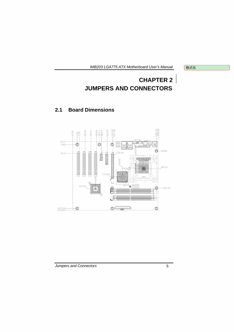
IMB203 LGA775 ATX Motherboard Userrsquos Manual
Jumpers and Connectors 5
CHAPTER 2 JUMPERS AND CONNECTORS
21 Board Dimensions
格式化
IMB203 LGA775 ATX Motherboard Userrsquos Manual
Jumpers and Connectors 6
22 Board Layout
IMB203 LGA775 ATX Motherboard Userrsquos Manual
Jumpers and Connectors 7
23 Jumper Settings Proper jumper settings configure the IMB203 to meet your application purpose
231 COM1 Mode Select Jumpers for RS-232422485 (JP1 JP3 JP4)
These jumpers select the COM1 portrsquos communication mode to operate RS-232 or RS-422485
Description Function Jumper Setting
RS-232 (Default)
JP1
JP3
JP4
RS-422 JP1 JP3
JP4
COM1
RS-485 JP1 JP3
JP4
IMB203 LGA775 ATX Motherboard Userrsquos Manual
Jumpers and Connectors 8
232 Audio Amplifier Jumper (JP2)
Description Function Jumper Setting
Disable
Audio Amplifier
Enable (Default)
IMB203 LGA775 ATX Motherboard Userrsquos Manual
Jumpers and Connectors 9
233 CMOS Clear Jumper (JP7) You may need to use this jumper is to clear the CMOS memory if incorrect BIOS settings
Description Function Jumper Setting
Normal (Default)
CMOS Clear
Clear CMOS
234 TPM DisableEnable Jumper (JP9)
Description Function Jumper Setting
Enable TPM (Default)
TPM Disable Enable
Disabled
IMB203 LGA775 ATX Motherboard Userrsquos Manual
Jumpers and Connectors 10
235 ME DisableEnable Jumper (JP10)
Description Function Jumper Setting
Enable (Default)
ME Disable Enable
Disable
刪除
IMB203 LGA775 ATX Motherboard Userrsquos Manual
Jumpers and Connectors 11
24 Connectors Connectors connect this board with other parts of the system Loose or improper connection might cause problems Make sure all connectors are properly and firmly connected
Label Connector
CN1 VGA
CN2 COM 1
CN3 Audio out Mic in
CN4 Keyboard Mouse
CN5 Print Port
CN6 CN7 USB Ports
CN14 ATX 2x2
CN16 COM 2
CN17 PCI Express x1 Slot
CN18 PCI Express x4 Slot
CN19 COM 3
CN25 COM 4
CN26 DIO
CN27 CN29 CN33 CN45 USB
CN31 FAN
CN36 CN37 CN41 CN42 CN46 CN47
SATA
CN50 ATX-24Pin
CN52 F_PANEL
IMB203 LGA775 ATX Motherboard Userrsquos Manual
Jumpers and Connectors 12
IMB203 LGA775 ATX Motherboard Userrsquos Manual
Jumpers and Connectors 13
241 VGA Connector (CN1) The board supports CRT VGA with a 15-pin D-Sub connector for the CRT VGA display
Pin Signal Pin Signal Pin Signal 1 Red 2 Green 3 Blue 4 NA 5 GND 6 GND 7 GND 8 GND 9 VCC 10 GND 11 NA 12 DDC DATA
13 Horizontal Sync 14 Vertical Sync 15 DDC CLK
242 COM1 Connector (CN2) The board has the onboard serial port COM1 (CN2) a 9-pin D-Sub connector on the rear IO to support RS-232422485 with jumper selectable RS-485 with auto-flow control
Pin Signal 1 DCD Data carrier detect 2 RXD Receive data 3 TXD Transmit data 4 DTR Data terminal ready 5 GND ground 6 DSR Data set ready 7 RTS Request to send 8 CTS Clear to send 9 RI Ring indicator
IMB203 LGA775 ATX Motherboard Userrsquos Manual
Jumpers and Connectors 14
243 COM2~COM4 Connectors (CN16 CN19 CN25) The board has the onboard serial ports COM2~4 (CN16 CN19 CN25) three 25-pin 254 pitch box-header to support RS-232
Pin Signal Pin Signal
1 Data Carrier Detect (DCD) 2 Data Set Ready
(DSR)
3 Receive Data (RXD) 4 Request to Send
(RTS)
5 Transmit Data (TXD) 6 Clear to Send
(CTS)
7 Data Terminal Ready (DTR) 8 Ring Indicator (RI)
9 Ground (GND) 10 NC
244 Audio Connector (CN3)
Color Signal
Green LINE_OUT
Red MIC_IN
IMB203 LGA775 ATX Motherboard Userrsquos Manual
Jumpers and Connectors 15
245 PS2 KeyboardMouse Connector (CN4) The board supports a keyboard and Mouse interface
Pin Signal Pin Signal
1 KB Data 7 MS Data
2 NC 8 NC
3 GND 9 GND
4 VCC 10 VCC
5 KB CLK 11 MS CLK
6 NC 12 NC
246 Print Port Connector (CN5)
Print Port Connector This board has a multi-mode parallel port to support the following modes 1 Standard Mode
IBM PCXT PCAT and PS2trade are compatible with bi-directional parallel port
2 Enhanced Mode Enhanced parallel port (EPP) is compatible with EPP 17 and EPP 19 (IEEE 1284 compliant)
3 High Speed Mode Microsoft and Hewlett Packard extended capabilities port (ECP) is IEEE 1284 compliant
Please refer to next page for the list of pin assignment
IMB203 LGA775 ATX Motherboard Userrsquos Manual
Jumpers and Connectors 16
Print Port Pin Assignment (Default)
Pin Signal 1 Data Carrier Detect (DCD) 2 Data Set Ready (DSR)
3 Receive Data (RXD)
4 Request to Send (RTS) 5 Transmit Data (TXD)
6 Clear to Send (CTS)
7 Data Terminal Ready (DTR) 8 Ring Indicator (RI)
9 Ground (GND)
247 USB Port Connector (CN6 CN7) The Universal Serial Bus (USB) port connector on the board is for the installation of peripherals supporting the USB interface The CN6CN7 consists of two 4-pin standard USB ports
Pin Signal
1 5 USB Vcc
2 6 USB -
3 7 USB +
4 8 USB GND
IMB203 LGA775 ATX Motherboard Userrsquos Manual
Jumpers and Connectors 17
248 USB Connectors (CN27 CN29 CN33 CN45) The 10-pin standard Universal Serial Bus (USB) connectors CN27293345 on this board are for installing versatile USB interface peripherals
Pin Signal Pin Signal 1 USB 2 USB
3 USB2- 4 USB3-
5 USB2+ 6 USB3+
7 GND 8 GND
9 GND 10 GND
CN45
Pin Signal Pin Signal 1 USB 2 USB
3 USB4- 4 USB5-
5 USB4+ 6 USB5+
7 GND 8 GND
10 GND
CN27 CN29 CN33
249 ATX 4 Pin 12V In Connector (CN14) You can connect it to the ATX12V power supply for CPU Core Voltage
Pin Signal 1 GND 2 GND 3 +12V 4 +12V
IMB203 LGA775 ATX Motherboard Userrsquos Manual
Jumpers and Connectors 18
2410 Digital IO Port (DIO) Connector (CN26) The board is equipped an 8-channel digital IO connector CN26 that meets requirements for a system customary automation control The digital IO can be configured to control cash drawers sense warning signals from an Uninterrupted Power System (UPS) or perform store security control The digital IO is controlled via software programming
Pin Signal Pin Signal
1 DO1 2 DI1
3 DO2 4 DI2
5 DO3 6 DI3
7 DO4 8 DI4
9 GND 10 GND
2411 CPU Fan Connector (CN31) A CPU fan is always needed for cooling CPU heat The CPU fan connector provides power to the CPU fan
Pin Signal 1 Ground 2 +12V 3 Rotation Detection4 Speed Control
2412 SATA Connectors (CN36 CN37 CN41 CN42
CN46 CN47) These SATA connectors are for high-speed SATA interface ports and they can be connected to hard disk devices
Pin Signal
1 GND
2 SATA_TX+
3 SATA_TX-
CN364146
IMB203 LGA775 ATX Motherboard Userrsquos Manual
Jumpers and Connectors 19
4 GND
5 SATA_RX-
6 SATA_RX+
7 GND
IMB203 LGA775 ATX Motherboard Userrsquos Manual
Jumpers and Connectors 20
2413 ATX Power Connector (CN50) Steady and sufficient power can be supplied to all components on the board by connecting the power connector Please make sure all components and devices are properly installed before connecting the power connector If you use a 24-pin ATX power supply please remove the small cover from the power connector before plugging in the power cord otherwise please do not remove it Pin Signal Pin Signal 1 33V 2 33V
3 GND 4 5V
5 GND 6 5V
7 GND 8 PWR
9 5VSB 10 12V
11 12V 12 33V
13 33V 14 -12V
15 GND 16 PS_ON
17 GND 18 GND
19 GND 20 -5V
21 5V 22 5V
23 5V 24 GND
IMB203 LGA775 ATX Motherboard Userrsquos Manual
Jumpers and Connectors 21
2414 Front Panel Connector (CN52)
Power LED
This 3-pin connector denoted as Pin 1 and Pin 5 connects the system power LED indicator to such a switch on the case Pin 1 is assigned as + and Pin 5 as - The Power LED lights up when the system is powered ON Pin 3 is defined as GND
External Speaker and Internal Buzzer Connector
Pin 2 4 6 and 8 can be connected to the case-mounted speaker unit or internal buzzer While connecting the CPU card to an internal buzzer please short pins 2-4 while connecting to an external speaker you need to set pins 2-4 to Open and connect the speaker cable to pin 8 (+) and pin 2 (-)
ATX Power OnOff Button
This 2-pin connector denoted as Pin 9 and 10 connects the front panelrsquos ATX power button to the CPU card which allows users to control ATX power supply to be power onoff
System Reset Switch
Pin 11 and 12 can be connected to the case-mounted reset switch that reboots your computer instead of turning OFF the power switch It is a better way to reboot your system for a longer life of the systemrsquos power supply
HDD Activity LED
This connection is linked to hard drive activity LED on the control panel LED flashes when HDD is being accessed Pin 13 and 14 connect the hard disk drive to the front panel HDD LED Pin 13 assigned as - and Pin 14 as +
IMB203 LGA775 ATX Motherboard Userrsquos Manual
Jumpers and Connectors 22
MEMO
IMB203 LGA775 ATX Motherboard Userrsquos Manual
Hardware Installation 23
CHAPTER 3 HARDWARE INSTALLATION
Before installing the processor please access Intelreg website for more detailed information httpwwwintelcom
31 Installing the Processor The LGA775 processor socket comes with a cover to protect the processor Please install the processor into the CPU socket step by step as below
Hold the hook (A) of the lever and push it down Pull the lever (B) aside to unlock the cover
IMB203 LGA775 ATX Motherboard Userrsquos Manual
Hardware Installation 24
Remove the plastic cap (E) from the cover
Open the cover (C) you can see the contact
Be careful not to touch the contact (D)
IMB203 LGA775 ATX Motherboard Userrsquos Manual
Hardware Installation 25
Place the CPU down into the socket Be careful not to touch the contact
Hold the edges of the CPU and orientate it as the marked direction (G) down into the socket to match the (H) and (F) locations
IMB203 LGA775 ATX Motherboard Userrsquos Manual
Hardware Installation 26
Slightly push down the cover and hook the lever (I~J) The CPU is completely locked
Orientate the CPU cooling fan to fixing holes on the board
IMB203 LGA775 ATX Motherboard Userrsquos Manual
Hardware Installation 27
Screw the CPU cooling fan onto the board
Make sure the CPU fan is plugged to the CPU fan connector
IMB203 LGA775 ATX Motherboard Userrsquos Manual
Hardware Installation 28
32 Installing the Memory The board supports four 240-pin DDR3 DIMM memory sockets with maximum memory capacity up to 16GB Please follow steps below to install the memory modules 1 Push down latches on each side of the DIMM socket 2 Align the memory module with the socket that notches of
memory module must match the socket keys for a correct installation
3 Install the memory module into the socket and push it firmly down until it is fully seated The socket latches are levered upwards and clipped on to the edges of the DIMM
4 Install any remaining DIMM modules
IMB203 LGA775 ATX Motherboard Userrsquos Manual
Hardware Description 29
CHAPTER 4 HARDWARE DESCRIPTION
41 Microprocessors The IMB203 Series supports Intelreg Coretrade 2 Quad Coretrade 2 Duo processors which make your system operated under Windowsreg XP and Linux environments The system performance depends on the microprocessor Make sure all correct settings are arranged for your installed microprocessor to prevent the CPU from damages
42 BIOS The IMB203 Series uses AMI Plug and Play BIOS with a single 32Mbit SPI Flash
43 System Memory The IMB203 Series supports four 240-pin DDR3 DIMM sockets for a maximum memory of 16GB DDR3 SDRAMs The memory module can come in sizes of 1GB 2GB and 4GB
IMB203 LGA775 ATX Motherboard Userrsquos Manual
Hardware Description 30
44 IO Port Address Map The Intelreg Coretrade 2 Extreme Intelreg Coretrade 2 Quad Coretrade 2 Duo CPUs can communicate via IO ports There are total 1KB port addresses available for assignment to other devices via IO expansion cards
Address Devices 000-01F DMA controller 1
020-02D 024-025 028-029 02C-02D Interrupt controller 1
02E-02F Forwarded to LPC(LPC Super IO ) 030-031 034-035 038-039 03C-03D
Interrupt controller 2
040-043 050-053 TimerCounter (8254) 060 Forwarded to LPC (Microcontroller) 061 NMI
062-066 Forwarded to LPC (Microcontroller) 070-077 Real time clock NMI 080-091 DMA page register
092 Processor IF(Reset Generator) 093-09F DMA page register 0A0-0BF Interrupt controller 2 0C0-0DF DMA controller 2
0F0 Processor IF 0F8-0FF Math processor 170-177 Forward to SATA (SATA Controller) 1F0-1F7 Forward to SATA (SATA Controller)
376 Forward to SATA(SATA Controller) 378-37F Parallel Port (LPT) 380-38F SDLC 2 3A0-3AF SDLC 1 3B0-3BF MDA video card
(to be continued)
IMB203 LGA775 ATX Motherboard Userrsquos Manual
Hardware Description 31
Address Devices 3C0-3CF EGA card 3D0-3DF CGA card
3F6 Forward to SATA(SATA Controller) 3F8-3FF Serial port 1 (COM1) 2F8-2FF Serial port 2 (COM2)
45 Interrupt Controller (IRQ) Map The IMB203 Series is a 100 PC compatible control board It consists of 16 interrupt request lines and four out of them can be programmable The mapping list of the 16 interrupt request lines is shown as the following table
IRQ Parity check error IRQ0 System Timer Output
IRQ1 Keyboard
IRQ2 Interrupt rerouting from IRQ8 through IRQ15
IRQ3 Serial port 2
IRQ4 Serial port 1
IRQ5 PCI Device Share
IRQ7 Parallel port
IRQ8 Real time clock
IRQ9 ACPI Controller
IRQ10 PCI Device Share
IRQ11 PCI Device Share
IRQ12 PS2 Mouse
IRQ13 Math coprocessor
IRQ14 SATA Primary (Legacy Mode)
IRQ15 SATA Secondary (Legacy Mode)
IMB203 LGA775 ATX Motherboard Userrsquos Manual
Hardware Description 32
MEMO
IMB203 LGA775 ATX Motherboard Userrsquos Manual
AMI BIOS Setup Utility 33
CHAPTER 5 AMI BIOS SETUP UTILITY
This chapter provides users with detailed description how to set up basic system configuration through the AMIBIOS8 BIOS setup utility 51 Starting To enter the setup screens follow the steps below 1 Turn on the computer and press the ltDelgt key immediately 2 After you press the ltDeletegt key the main BIOS setup menu
displays You can access the other setup screens from the main BIOS setup menu such as the Chipset and Power menus
52 Navigation Keys The BIOS setuputility uses a key-based navigation system called hot keys Most of the BIOS setup utility hot keys can be used at any time during the setup navigation process These keys include ltF1gt ltF10gt ltEntergt ltESCgt ltArrowgt keys and so on
Note Some of navigation keys differ from one screen to another
IMB203 LGA775 ATX Motherboard Userrsquos Manual
AMI BIOS Setup Utility 34
LeftRight The Left ltArrowgt keys allow you to select a setup screen
UpDown The Up and Down ltArrowgt keys allow you to select a setup screen or sub-screen
+minus PlusMinus The Plus and Minus ltArrowgt keys allow you to change the field value of a particular setup item
Tab The ltTabgt key allows you to select setup fields
F1 The ltF1gt key allows you to display the General Help screen
F10 The ltF10gt key allows you to save any changes you have made and exit Setup Press the ltF10gt key to save your changes
Esc
The ltEscgt key allows you to discard any changes you have made and exit the Setup Press the ltEscgt key to exit the setup without saving your changes
Enter
The ltEntergt key allows you to display or change the setup option listed for a particular setup item The ltEntergt key can also allow you to display the setup sub- screens
IMB203 LGA775 ATX Motherboard Userrsquos Manual
AMI BIOS Setup Utility 35
53 Main Menu When you first enter the Setup Utility you will enter the Main setup screen You can always return to the Main setup screen by selecting the Main tab There are two Main Setup options They are described in this section The Main BIOS Setup screen is shown below
System TimeDate
Use this option to change the system time and date Highlight System Time or System Date using the ltArrowgt keys Enter new values through the keyboard Press the ltTabgt key or the ltArrowgt keys to move between fields The date must be entered in MMDDYY format The time is entered in HHMMSS format
IMB203 LGA775 ATX Motherboard Userrsquos Manual
AMI BIOS Setup Utility 36
54 Advanced Menu The Advanced menu allows users to set configuration of the CPU and other system devices You can select any of the items in the left frame of the screen to go to the sub menus
CPU Configuration IDE Configuration SuperIO Configuration Hardware Health Configuration ACPI Configuration AHCI Configuration Intel iAMT Configuration Intel VT-d Configuration MPS Configuration PCI Express Configuration Trusted Computing USB Configuration
For items marked with ldquo rdquo please press ltEntergt for more options
IMB203 LGA775 ATX Motherboard Userrsquos Manual
AMI BIOS Setup Utility 37
CPU Configuration This screen shows the CPU Configuration and you can change the value of the selected option
Max CPUID Value Limit
You can enable this item to let legacy operating systems boot even without support for CPUs with extended CPU ID functions
Execute-Disable Bit Capability This item helps you enable or disable the No-Execution Page Protection Technology
Core Multi-Processing This feature controls the functionality of the Core Multi-Processing to allow the processor to execute multitasking function
PECI Use this item PECI (Platform Environment Control Interface) to execute the processor temperature monitoring and management
IMB203 LGA775 ATX Motherboard Userrsquos Manual
AMI BIOS Setup Utility 38
Intel (R) C-STATE tech Use this item to enable or disable the C-State technology
IDE Configuration You can use this screen to select options for the IDE Configuration and change the value of the selected option A description of the selected item appears on the right side of the screen For items marked with ldquo rdquo please press ltEntergt for more options
SATA1 Configuration
Use this item to control the onboard SATA controller Here are the options for your selection Compatible Disabled and Enhanced
Configure SATA1 as Use this item to choose the SATA operation mode Here are the options for your selection IDE and AHCI
SATA2 Configuration Use this item to control the onboard SATA controller Here are the options for your selection Enhanced and Disabled
IMB203 LGA775 ATX Motherboard Userrsquos Manual
AMI BIOS Setup Utility 39
PrimarySecondaryThird IDE Master Select one of the hard disk drives to configure IDE devices installed in the system by pressing ltEntergt for more options
Fifth IDE Master Select one of the hard disk drives to configure IDE devices installed in the system by pressing ltEntergt for more options
IMB203 LGA775 ATX Motherboard Userrsquos Manual
AMI BIOS Setup Utility 40
SuperIO Configuration You can use this screen to select options for the SuperIO Configuration and change the value of the selected option A description of the selected item appears on the right side of the screen
Serial Port1 Address
This option specifies the base IO port address and Interrupt Request address of serial port 1 The Optimal setting is 3F8IRQ4 The Fail-Safe default setting is Disabled
Serial Port2 Address This option specifies the base IO port address and Interrupt Request address of serial port 2 The Optimal setting is 2F8IRQ3 The Fail-Safe setting is Disabled
Parallel Port Address This item allows you to determine the IO address for onboard parallel port There are several options for your selection
Parallel Port Mode
IMB203 LGA775 ATX Motherboard Userrsquos Manual
AMI BIOS Setup Utility 41
Select an operating mode for the onboard parallel (printer) port
Parallel Port IRQ Use this item to set up the IRQ for onboard parallel port
Serial Port3 Address This item specifies the base IO port address and Interrupt Request address of serial port 3 The Optimal setting is 3E8IRQ11 The Fail-Safe default setting is Disabled
Serial Port3 IRQ This item specifies the IRQ used by the serial port 3
Serial Port4 Address This item specifies the base IO port address and Interrupt Request address of serial port 4 The Optimal setting is 2E8IRQ10 The Fail-Safe default setting is Disabled
Serial Port4 IRQ This item specifies the IRQ used by the serial port 4
IMB203 LGA775 ATX Motherboard Userrsquos Manual
AMI BIOS Setup Utility 42
Hardware Health Configuration This screen shows the Hardware Health Configuration and a description of the selected item appears on the right side of the screen
HW Health Configuration
This screen displays the temperature of CPU and System Fan Speed Vcore etc
IMB203 LGA775 ATX Motherboard Userrsquos Manual
AMI BIOS Setup Utility 43
ACPI Configuration You can use this screen to select options for the ACPI Configuration and change the value of the selected option A description of the selected item appears on the right side of the screen
General ACPI Configuration
Scroll to this item and press ltEntergt to view the General ACPI Configuration sub menu which contains General ACPI (Advanced Configuration and Power Management Interface) options for your configuration
Advanced ACPI Configuration Scroll to this item and press ltEntergt to view the Advanced ACPI Configuration sub menu which contains Advanced ACPI (Advanced Configuration and Power Management Interface) options for your configuration
Chipset ACPI Configuration Scroll to this item and press ltEntergt to view the Chipset ACPI Configuration sub menu which contains Chipset ACPI (Advanced Configuration and Power Management
IMB203 LGA775 ATX Motherboard Userrsquos Manual
AMI BIOS Setup Utility 44
Interface) options for your configuration AHCI Configuration
You can use this screen to select options for the AHCI Configuration and change the value of the selected option A description of the selected item appears on the right side of the screen
AHCI BIOS Support You can enable or disable this item to control the AHCI function of the SATA controller
IMB203 LGA775 ATX Motherboard Userrsquos Manual
AMI BIOS Setup Utility 45
Intel iAMT Configuration You can use this screen to select options for the Intel iAMT Configuration and change the value of the selected option A description of the selected item appears on the right side of the screen
Intel iAMT Support
You can enable this item to support iAMT (active management technology) function to follow up the procedure for the access to AMI program screen
Unconfigure iAMTME Use this item to unconfigure the iAMTME settings
IMB203 LGA775 ATX Motherboard Userrsquos Manual
AMI BIOS Setup Utility 46
Intel VT-d Configuration You can use this screen to select options for the Intel VT-d Configuration and change the value of the selected option A description of the selected item appears on the right side of the screen
Intel VT-d Virtualization Technology for Directed IO (VT-d) extends Virtualization Technology (VT) roadmap by providing hardware assists for virtualization solution VT-d can help end users improve security and reliability of the systems and also improve performance of IO devices in virtualized environment Here are the options for your selection Disabled and Enabled
IMB203 LGA775 ATX Motherboard Userrsquos Manual
AMI BIOS Setup Utility 47
Remote Access Configuration You can use this screen to select options for the Remote Access Configuration and change the value of the selected option A description of the selected item appears on the right side of the screen
Remote Access Use this item to enable or disable the Remote Access function
IMB203 LGA775 ATX Motherboard Userrsquos Manual
AMI BIOS Setup Utility 48
PCI Express Configuration This screen shows the PCI Express Configuration and you can change its value A description of the selected item appears on the right side of the screen
Active State Power-Management
Use this item to enable or disable the function of Active State Power-Management to provide you with lower power consumption The default setting is Disabled
IMB203 LGA775 ATX Motherboard Userrsquos Manual
AMI BIOS Setup Utility 49
Trusted Computing You can use this screen to select options for the Trusted Computing and change the value of the selected option A description of the selected item appears on the right side of the screen
TCGTPM SUPPORT Use this item to control the Trusted Platform Module (TPM) function
IMB203 LGA775 ATX Motherboard Userrsquos Manual
AMI BIOS Setup Utility 50
USB Configuration You can use this screen to select options for the USB Configuration and change the value of the selected option A description of the selected item appears on the right side of the screen
USB Functions
This item allows you to enable or disable USB functions
Legacy USB Support Use this item to enable or disable support for USB device on legacy operating system The default setting is Enabled
USB 20 Controller Mode Use this item to configure the USB 20 controller The default setting is HiSpeed
BIOS EHCI Hand-Off Enabling this item provide the support for operating systems without an EHCI hand-off feature The default setting is Enabled
IMB203 LGA775 ATX Motherboard Userrsquos Manual
AMI BIOS Setup Utility 51
IMB203 LGA775 ATX Motherboard Userrsquos Manual
AMI BIOS Setup Utility 52
55 PCI PnP Menu The PCI PnP menu allows users to change the advanced settings for PCIPnP devices
Clear NVRAM
Use this item to clear the data in the NVRAM (CMOS) Here are the options for your selection No and Yes
Plug amp Play OS When the setting is No Use this item to configure all the devices in the system When the setting is Yes and if you install a Plug and Play operating system the operating system configures the Plug and Play devices not required for boot The default setting is No
IMB203 LGA775 ATX Motherboard Userrsquos Manual
AMI BIOS Setup Utility 53
PCI Latency Timer This item controls how long a PCI device can hold the PCI bus before another takes over The longer the latency the longer the PCI device can retain control of the bus before handing it over to another PCI device There are several options for your selection
Allocate IRQ to PCI VGA This item allows BIOS to choose an IRQ to assign for the PCI VGA card Here are the options for your selection No and Yes
Palette Snooping Some old graphic controllers need to ldquosnooprdquo on the VGA palette and then map it to their display as a way to provide boot information and VGA compatibility This item allows such snooping to take place Here are the options for your selection Disabled and Enabled
PCI IDE BusMaster This item is a toggle for the built-in driver that allows the onboard IDE controller to perform DMA (Direct Memory Access) transfer Here are the options for your selection Disabled and Enabled
OffBoard PCIISA IDE Card This item is for any other non-onboard PCIISA IDE controller adapter There are several options for your selection
IRQ3457910111415 These items will allow you to assign each system interrupt a type depending on the type of device using the interrupt The option ldquoAvailablerdquo means the IRQ is going to assign automatically Here are the options for your selection Available and Reserved
DMA Channel 013567 These items will allow you to assign each DMA channel a type depending on the type of device using the channel The option ldquoAvailablerdquo means the channel is going to assign automatically Here are the options for your selection Available and Reserved
IMB203 LGA775 ATX Motherboard Userrsquos Manual
AMI BIOS Setup Utility 54
56 Boot Menu The Boot menu allows users to change boot options of the system You can select any of the items in the left frame of the screen to go to the sub menus
Boot Settings Configuration Boot Device Priority Removable Drives
For items marked with ldquo rdquo please press ltEntergt for more options
IMB203 LGA775 ATX Motherboard Userrsquos Manual
AMI BIOS Setup Utility 55
Boot Settings Configuration
Quick Boot
Enabling this item lets the BIOS skip some power on self tests (POST) The default setting is Enabled
AddOn ROM Display Mode This item selects the display mode for option ROM The default setting is Force BIOS
Boot Num-Lock Use this item to select the power-on state for the NumLock The default setting is On
PS2 Mouse Support This item determines if the BIOS should reserve IRQ12 for the PS2 mouse or allow other devices to make use of this IRQ Here are the options for your selection Auto Enabled and Disabled
Wait For lsquoF1rsquo Of Error If this item is enabled the system waits for the F1 key to be pressed when error occurs The default setting is Enabled
Hit lsquoDELrsquo Message Display If this item is enabled the system displays the message
IMB203 LGA775 ATX Motherboard Userrsquos Manual
AMI BIOS Setup Utility 56
ldquoPress DEL to run Setuprdquo during POST The default setting is Enabled
Interrupt 19 Capture If this item is enabled this function makes the option ROMs to trap Interrupt 19 The default setting is Disabled
Boot Device Priority The Boot Device Priority screen specifies the boot device priority sequence from the available devices
IMB203 LGA775 ATX Motherboard Userrsquos Manual
AMI BIOS Setup Utility 57
Removable Drives Use this screen to view the removable drives in the system The BIOS will attempt to arrange the removable drive boot sequence automatically You can also change the booting sequence
IMB203 LGA775 ATX Motherboard Userrsquos Manual
AMI BIOS Setup Utility 58
57 Security Menu The Security menu allows users to change the security settings for the system
Supervisor Password
This item indicates whether a supervisor password has been set If the password has been installed Installed displays If not Not Installed displays
User Password This item indicates whether a user password has been set If the password has been installed Installed displays If not Not Installed displays
Change Supervisor Password Select this option and press ltEntergt to access the sub menu You can use the sub menu to change the supervisor password
Change User Password Select this option and press ltEntergt to access the sub menu You can use the sub menu to change the user password
IMB203 LGA775 ATX Motherboard Userrsquos Manual
AMI BIOS Setup Utility 59
58 Chipset Menu The Chipset menu allows users to change the advanced chipset settings You can select any of the items in the left frame of the screen to go to the sub menus
North Bridge Configuration South Bridge Configuration ME Subsystem Configuration
For items marked with ldquo rdquo please press ltEntergt for more options
IMB203 LGA775 ATX Motherboard Userrsquos Manual
AMI BIOS Setup Utility 60
North Bridge Configuration
Memory Remap Feature
Use this item to enable or disable the remapping of the overlapped PCI memory above the total physical memory Only 64-bit OS supports this function
DRAM Frequency This item allows you to control the Memory Clock
Configure DRAM Timing by SPD This item can enable or disable DRAM timing by SPD (Serial Presence Detect) device which is a small EEPROM chip on the memory module containing important information about the module speed size addressing mode and various parameters
Memory Hole You can reserve this area of system memory for ISA adapter ROM When this area is reserved it cannot be cached Check the user information of peripherals that need to use this area o f system memory for the memory requirements Here are the options Disabled and 15M-16M
IMB203 LGA775 ATX Motherboard Userrsquos Manual
AMI BIOS Setup Utility 61
Initiate Graphic Adapter When using multiple graphics cards this item can select which graphics controller to be the primary display device during boot
IGD Graphics Mode Select This item allows you to select the amount of system memory used by the internal graphics device
PEG Port ConfigurationPEG Port This item is a toggle to enable or disable the PCI Express port Here are the options for your selection Auto and Disabled
Video Function Configuration Press ltEntergt for the sub-menu for setting up video function
IMB203 LGA775 ATX Motherboard Userrsquos Manual
AMI BIOS Setup Utility 62
South Bridge Configuration
GbE Wake Up From S5 This item specifies whether the system will be awakened from the S5 power
HDA Controller This item allows you to enable or disable the HD audio support
Restore on AC Power Loss This item can control how the PC will behave once power is restored following a power outage or other unexpected shutdown
PCIE Port Configuration This item allows you to set or disable the PCI Express Ports
IMB203 LGA775 ATX Motherboard Userrsquos Manual
AMI BIOS Setup Utility 63
ME Subsystem Configuration
It is strongly recommended that you do not modify these options unless you are an advanced user
IMB203 LGA775 ATX Motherboard Userrsquos Manual
AMI BIOS Setup Utility 64
59 Exit Menu The Exit menu allows users to load your system configuration with optimal or failsafe default values
Save Changes and Exit
When you have completed the system configuration changes select this option to leave Setup and reboot the computer so the new system configuration parameters can take effect Select Save Changes and Exit from the Exit menu and press ltEntergt Select Ok to save changes and exit
Discard Changes and Exit Select this option to quit Setup without making any permanent changes to the system configuration Select Discard Changes and Exit from the Exit menu and press ltEntergt Select Ok to discard changes and exit
Load Optimal Defaults It automatically sets all Setup options to a complete set of default settings when you select this option The Optimal settings are designed for maximum system performance but may not work best for all computer applications In particular do not use the Optimal Setup options if your
IMB203 LGA775 ATX Motherboard Userrsquos Manual
AMI BIOS Setup Utility 65
computer is experiencing system configuration problems Select Load Optimal Defaults from the Exit menu and press ltEntergt
Load Fail-Safe Defaults It automatically sets all Setup options to a complete set of default settings when you select this option The Fail-Safe settings are designed for maximum system stability but not maximum performance Select the Fail-Safe Setup options if your computer is experiencing system configuration problems Select Load Fail-Safe Defaults from the Exit menu and press ltEntergt Select Ok to load Fail-Safe defaults
IMB203 LGA775 ATX Motherboard Userrsquos Manual
AMI BIOS Setup Utility 66
MEMO
IMB203 LGA775 ATX Motherboard Userrsquos Manual
Installation of Drivers 67
CHPATER 6 INSTALLATION OF DRIVERS
The device drivers are located on the Product Information CD-ROM that comes with the IMB203 Series package The auto-run function of drivers will guide you to install the utilities and device drivers under a Windows system You can follow the onscreen instructions to install these devices
Chipse VGA LAN Audio iAMT MEI
61 Installing Chipset Driver 1 Run the SETUPEXE program from the driver directory in
your driver CD Click ldquoNextrdquo to next step
IMB203 LGA775 ATX Motherboard Userrsquos Manual
Installation of Drivers 68
2 An Intelreg License Agreement appears to show you the important information Click ldquoYesrdquo to next step
3 Refer to the Readme file below to view the system requirements and installation information
IMB203 LGA775 ATX Motherboard Userrsquos Manual
Installation of Drivers 69
3-1 Please wait while running the following setup operations
3-2 Please wait while running the following setup operations
IMB203 LGA775 ATX Motherboard Userrsquos Manual
Installation of Drivers 70
4 Click ldquoFinishrdquo to complete the setup process
5 You will be asked to reboot your computer when the installation is completed Please click ldquoYes I want to restart my computer nowrdquo if you donrsquot need to install any other drivers Otherwise please click ldquoNo I will restart my computer laterrdquo and go on next step
IMB203 LGA775 ATX Motherboard Userrsquos Manual
Installation of Drivers 71
62 Installing VGA Driver 1 Run the SETUPEXE program from the driver directory in
your driver CD Click ldquoNextrdquo to next step
2 An Intelreg License Agreement appears to show you the
important information Click ldquoYesrdquo to next step
IMB203 LGA775 ATX Motherboard Userrsquos Manual
Installation of Drivers 72
3 The message of Readme File Information appears to show you the system requirements and installation information Please click ldquoNextrdquo
4 Please wait while running the following setup operations
When this message appears please click ldquoNextrdquo
IMB203 LGA775 ATX Motherboard Userrsquos Manual
Installation of Drivers 73
5 Click ldquoFinishrdquo to complete the setup process
6 You will be asked to reboot your computer when the installation is completed Please click ldquoYes I want to restart my computer nowrdquo if you donrsquot need to install any other drivers Otherwise please click ldquoNo I will restart my computer laterrdquo and click ldquoFinishrdquo to complete the installation
IMB203 LGA775 ATX Motherboard Userrsquos Manual
Installation of Drivers 74
63 Installing LAN Driver
11 Run the InstallShield Wizard for Network Connections from
the driver directory in your driver CD Click ldquoNextrdquo to next step
IMB203 LGA775 ATX Motherboard Userrsquos Manual
Installation of Drivers 75
12 An Intelreg License Agreement appears to show you the important information Click ldquoYesrdquo to next step
13 A Setup Options window appears that you can select the
program features you want to install
IMB203 LGA775 ATX Motherboard Userrsquos Manual
Installation of Drivers 76
2 Click ldquoInstallrdquo to start the installation
3 Please wait while running the following installation operation
IMB203 LGA775 ATX Motherboard Userrsquos Manual
Installation of Drivers 77
4 Click ldquoFinishrdquo to complete the installation
Note The Driver item [Wake on Directed Packet] default is Enabled under Windows Vista
格式化 字型 (符號) Arial
格式化 字型 (符號) Arial
格式化 字型 斜體 字型色彩 黑色 (符號) Arial 非加寬 緊縮
格式化 字型 斜體 字型色彩 黑色 (符號) Arial 非加寬 緊縮
格式化 字型 (符號) Arial 非加寬 緊縮
IMB203 LGA775 ATX Motherboard Userrsquos Manual
Installation of Drivers 78
64 Installing AUDIO Driver 1 Run the InstallShield Wizard for Realtek High Definition
Audio Driver from the driver directory in your driver CD Click ldquoNextrdquo to next step
IMB203 LGA775 ATX Motherboard Userrsquos Manual
Installation of Drivers 79
2 Click ldquoInstallrdquo to start the installation and wait while running the installation operation
3 Click ldquoFinishrdquo to complete the installation
IMB203 LGA775 ATX Motherboard Userrsquos Manual
Installation of Drivers 80
65 Installing iAMT (Active Management Technology) Driver
Note You must download and properly install the required NET version 35 provided from a separate downloading of the actual FimwareTools kit releases posted on VIP prior to loading the MEILMS Driver stack
651 LMS_SOL Setup
1 Run the setup program to install Intelreg Active Management Technology onto your computer It is strongly recommended that you exit all programs before continuing Click ldquoNextrdquo to next step
格式化 字型 (符號) Arial
格式化 字型 (符號) Arial 非加寬 緊縮
IMB203 LGA775 ATX Motherboard Userrsquos Manual
Installation of Drivers 81
2 An Intelreg license agreement appears that you need to continue the setup program by clicking ldquoYesrdquo to accept the terms
IMB203 LGA775 ATX Motherboard Userrsquos Manual
Installation of Drivers 82
3 Refer to the Readme file below to view the system requirements and installation information Click ldquoNextrdquo to next setup
4 Please wait while running the following installation operation
IMB203 LGA775 ATX Motherboard Userrsquos Manual
Installation of Drivers 83
5 Click ldquoFinishrdquo to complete the installation
IMB203 LGA775 ATX Motherboard Userrsquos Manual
Installation of Drivers 84
652 LMS_SOL_IS Setup
1 Run the setup program to install Intelreg Active Management Technology onto your computer It is strongly recommended that you exit all programs before continuing Click ldquoNextrdquo to next step
IMB203 LGA775 ATX Motherboard Userrsquos Manual
Installation of Drivers 85
2 An Intelreg license agreement appears that you need to continue the setup program by clicking ldquoYesrdquo to accept the terms
IMB203 LGA775 ATX Motherboard Userrsquos Manual
Installation of Drivers 86
3 Refer to the Readme file below to view the system requirements and installation information Click ldquoNextrdquo to next setup
4 Please wait while running the following installation operation
IMB203 LGA775 ATX Motherboard Userrsquos Manual
Installation of Drivers 87
5 Click ldquoFinishrdquo to complete the installation
IMB203 LGA775 ATX Motherboard Userrsquos Manual
Installation of Drivers 88
66 Installing MEI (Management Engine Interface) Driver
Note You must download and properly install the required NET version 35 provided from a separate downloading of the actual FimwareTools kit releases posted on VIP prior to loading the MEILMS Driver stack
1 Run the setup program to install Intelreg Management Engine
Interface onto your computer It is strongly recommended that you exit all programs before continuing Click ldquoNextrdquo to next step
格式化 字型 (符號) Arial
格式化 字型 (符號) Arial 非加寬 緊縮
IMB203 LGA775 ATX Motherboard Userrsquos Manual
Installation of Drivers 89
2 An Intelreg license agreement appears that you need to continue the setup program by clicking ldquoYesrdquo to accept the terms
IMB203 LGA775 ATX Motherboard Userrsquos Manual
Installation of Drivers 90
3 Refer to the Readme file below to view the system requirements and installation information Click ldquoNextrdquo to next setup
4 Please wait while running the following installation operation
IMB203 LGA775 ATX Motherboard Userrsquos Manual
Installation of Drivers 91
5 Click ldquoFinishrdquo to complete the installation
IMB203 LGA775 ATX Motherboard Userrsquos Manual
Installation of Drivers 92
MEMO
IMB203 LGA775 ATX Motherboard Userrsquos Manual
Watchdog Timer 93
APPENDIX A WATCHDOG TIMER
Watchdog Timer Setting After the system stops working for a while it can be auto-reset by the Watchdog Timer The integrated Watchdog Timer can be set up in the system reset mode by program
Using the Watchdog Function Start darr Un-Lock WDT O 2E 87 Un-lock super IO
O 2E 87 Un-lock super IO darr Set WDT Function O 2E 2D O 2F 20 Select Logic device O 2E 07 O 2F 08 darr Activate WDT O 2E 30
O 2F 01 Set Second or Minute O 2E F5
O 2F N N=00 or 08(See below table) darr Set base timer O 2E F6
O 2F M=000102hellipFF(Hex) Value=0 to 255 darr WDT counting
re-set timer O 2E F6
O 2F M M=000102hellipFF(See below table) darr
格式化
格式化 項目符號及編號
格式化 項目符號及編號
格式化 字型 8 點 字型色彩黑色
格式化 字型 8 點 字型色彩黑色
格式化 定位點 1257 字元左 + 不在 1012 字元 + 1386字元
格式化 字型 8 點 字型色彩黑色
格式化 定位點 1257 字元左 + 不在 134 字元 + 1362字元
格式化 字型色彩 黑色
格式化 字型色彩 黑色
刪除
IMB203 LGA775 ATX Motherboard Userrsquos Manual
Watchdog Timer 94
IF No re-set timer WDT time-out generate RESET IF to disable WDT O 2E 30
O 2F 00 Can be disable at any time
N=00
M= 00h Time-out Disable 01h Time-out occurs after 1 second 02h Time-out occurs after 2 second 03h Time-out occurs after 3 second helliphelliphelliphelliphelliphelliphelliphelliphellip FFh Time-out occurs after 255 second
N=08
M= 00h Time-out Disable 01h Time-out occurs after 1 minute 02h Time-out occurs after 2 minutes 03h Time-out occurs after 3 minutes helliphelliphelliphelliphelliphelliphelliphelliphellip
FFh Time-out occurs after 255 minutes
格式化 字型色彩 黑色
格式化 字型色彩 黑色
IMB203 LGA775 ATX Motherboard Userrsquos Manual
PCI IRQ Routing 95
APPENDIX B PCI IRQ ROUTING
PICMG PCI IRQ Routing
Device ID Slot Int
PCI Slot 0 31 0 BCDA PCI Slot 1 30 1 CDAB PCI Slot 2 29 2 DABC PCI Slot 3 28 3 ABCD
IMB203 LGA775 ATX Motherboard Userrsquos Manual
PCI IRQ Routing 96
MEMO
IMB203 LGA775 ATX Motherboard Userrsquos Manual
Configuring SATA for RAID Function 97
APPENDIX C CONFIGURING SATA FOR RAID
FUNCTION
Configuring SATA Hard Drive(s) for RAID Function (Controller IntelregICH10DODO DH only) Please follow up the steps below to configure SATA hard drive(s) (1) Install SATA hard drive(s) in your system (2) Enter the BIOS Setup to configure SATA controller mode and boot
sequence (3) Configure RAID by the RAID BIOS (4) Install the SATA controller driver during the OS installation Before you begin the SATA configuration please prepare (a) Two SATA hard drives (to ensure optimal performance it is
recommended that you use two hard drives with identical model and capacity) If you do not want to create RAID with the SATA controller you may prepare only one hard drive
(b) An empty formatted floppy disk (c) Windows XP setup disk (1) Installing SATA hard drive(s) in your system
Connect one end of the SATA signal cable to the rear of the SATA hard drive and the other end to available SATA port(s) on the board Then connect the power connector of power supply to the hard drive
(2) Configuring SATA controller mode and boot sequence by the BIOS Setup You have to make sure whether the SATA controller is configured correctly by system BIOS Setup and set up BIOS boot sequence for the SATA hard drive(s)
IMB203 LGA775 ATX Motherboard Userrsquos Manual
Configuring SATA for RAID Function 98
(2)-1-1 Turn on your system and then press the Del button to enter BIOS Setup during running POST (Power-On Self Test) If you want to create RAID just go to the Advanced Settings menuIDE configuration select the Configure SATA1 as and press ltEntergt for more options
IMB203 LGA775 ATX Motherboard Userrsquos Manual
Configuring SATA for RAID Function 99
(2)-1-2 A list of options appears please select RAID
IMB203 LGA775 ATX Motherboard Userrsquos Manual
Configuring SATA for RAID Function 100
(2)-2 Set CDROM for First Boot Device under the Boot Settings menu to boot CD-ROM after system restarts
(2)-3 Save and exit the BIOS Setup
IMB203 LGA775 ATX Motherboard Userrsquos Manual
Configuring SATA for RAID Function 101
(3) Configuring RAID by the RAID BIOS Enter the RAID BIOS setup utility to configure a RAID array Skip this step and proceed to Section 4 if you do not want to create a RAID (3)-1 After the POST memory testing and before the operating
system booting a message Press ltCtrl-Igt to enter Configuration Utility shows up accordingly press ltCTRL+ Igt to enter the RAID BIOS setup utility
(3)-2 After you press ltCTRL+ Igt the Create RAID Volume screen will appear If you want to create a RAID array select the Create RAID Volume option in the Main Menu and press ENTER
IMB203 LGA775 ATX Motherboard Userrsquos Manual
Configuring SATA for RAID Function 102
(3)-3-1 After entering the CREATE VOLUME MENU screen you can type the disk array name with 1~16 letters (letters cannot be special characters) in the item ldquoNamerdquo
(3)-3-2 When finished press ENTER to select a RAID level There are three RAID levels RAID0 RAID1 and RAID5 amp RAID10 Select a RAID level and press ENTER
IMB203 LGA775 ATX Motherboard Userrsquos Manual
Configuring SATA for RAID Function 103
(3)-4 Set the stripe block size The KB is the standard unit of stripe block size The stripe block size can be 4KB to 128KB After the setting press ENTER for the array capacity
(3)-5 After setting all the items on the menu select Create Volume
and press ENTER to start creating the RAID array
IMB203 LGA775 ATX Motherboard Userrsquos Manual
Configuring SATA for RAID Function 104
(3)-6 When prompting the confirmation press ldquoYldquo to create this volume or ldquoNldquo to cancel the creation
After the creation is completed you can see detailed information about the RAID Array in the DISKVOLUME INFORMATION section including RAID mode disk block size disk name and disk capacity etc
IMB203 LGA775 ATX Motherboard Userrsquos Manual
Configuring SATA for RAID Function 105
Delete RAID Volume If you want to delete a RAID volume select the Delete RAID Volume option in Main Menu Press ENTER and follow on-screen instructions
Please press [ESC] to exit the RAID BIOS utility Now you can proceed to install a SATA driver controller and the operating system
IMB203 LGA775 ATX Motherboard Userrsquos Manual
Configuring SATA for RAID Function 106
(4) Making a SATA Driver Disk To install the operating system onto a serial ATA hard disk successfully you need to install the SATA controller driver during the OS installation Without the driver the hard disk may not be recognized during the Windows setup process First of all please format a blank floppy disk Secondly follow up these steps below to produce a SATA driver disk Users can insert the Driver CD and the formatted blank floppy disk in another system And then please copy all of file of the f6flpy32 folder in the Driver CD to a floppy disk Note Please copy all of file of the f6flpy64 folder if installing 64-bit
Windows Operating System
IMB203 LGA775 ATX Motherboard Userrsquos Manual
Configuring SATA for RAID Function 107
(5) Installing the SATA controller driver during the OS installation Now the SATA driver disk is ready and BIOS settings configured you can proceed to install Windows 2000XP onto your SATA hard drive using the SATA driver Here is an example for Windows XP installation (5)-1 Restart your system to boot the Windows 2000XP Setup disk
and press F6 button as soon as you see the message Press F6 if you need to install a 3rd party SCSI or RAID driver After pressing the F6 button there will be a few moments for some files being loaded before next screen appears
IMB203 LGA775 ATX Motherboard Userrsquos Manual
Configuring SATA for RAID Function 108
(5)-2 When you see the screen below insert the floppy disk containing the SATA driver and press ldquoSrdquo
(5)-3 If the Setup correctly recognizes the driver of the floppy disk
a controller menu will appear below Use the ARROW keys to select Intel(R) ICH8RICH9RICH10RDO SATA RAID Controller and press ENTER Then it will begin to load the SATA driver from the floppy disk
IMB203 LGA775 ATX Motherboard Userrsquos Manual
Configuring SATA for RAID Function 109
Note If a message on the screen saying that one or some file(s) cannot be found please check the floppy disk or copy the correct SATA driver again from the driver CD
IMB203 LGA775 ATX Motherboard Userrsquos Manual
Configuring SATA for RAID Function 110
MEMO
IMB203 LGA775 ATX Motherboard Userrsquos Manual
iAMT Settings 111
APPENDIX D iAMT SETTINGS
The Intelreg Active Management Technology (Intelreg iAMT) has decreased a major barrier to IT efficiency that uses built-in platform capabilities and popular third-party management and security applications to allow IT a better discovering healing and protection their networked computing assets In order to utilize Intel iAMT you must enter the ME BIOS (CTRL + P during system startup) change the ME BIOS password and then select ldquoIntelreg iAMTrdquo as the manageability feature
D1 Entering MEBx 1 You must go to BIOS TO start iAMT function 2 Exit from BIOS after starting iAMT and press Ctrl+P to enter MEBx Setting
It is better to press Ctrl+P before the screen popping out
格式化
IMB203 LGA775 ATX Motherboard Userrsquos Manual
iAMT Settings 112
D2 Set amp Change Password 1 You will be asked to set a password when first log in The default
password is lsquoadminrsquo
2 You will be asked to change the password before setting ME
Change Password
IMB203 LGA775 ATX Motherboard Userrsquos Manual
iAMT Settings 113
3 You must confirm your new password while revising (as Remark 1)
Remark 1 The new password must contain (example 11qqQQ) (default value)
Eight characters
One upper case
One lower case
One number
One special symbol such as $ or
( excepted)
Underline ( _ ) and space are valid characters for password but they wonrsquot make higher complexity
IMB203 LGA775 ATX Motherboard Userrsquos Manual
iAMT Settings 114
D3 Intelreg iAMT Settings 1 Select Intelreg iAMT Configuration and press ltENTERgt
2 Key in the Host Name If Intelreg iAMT set to lsquoDHCPlsquo the Host name must be identical to the operating system mechanic
IMB203 LGA775 ATX Motherboard Userrsquos Manual
iAMT Settings 115
3 Select TCPIP to get into Network interface and set it to lsquoENABLEDrsquo into DHCP Mode and set it to lsquoDISABLEDrsquo (as Remark 2) into Domain name and set the Intel Management Engine domain name such as lsquoAMTintelcomrsquo
(3-1)
(3-2)
IMB203 LGA775 ATX Motherboard Userrsquos Manual
iAMT Settings 116
Remark 2 DHCP Mode lsquoDISABLEDlsquo if DHCP Mode is disabled you can make the following settings
IP address
Subnet mask
IMB203 LGA775 ATX Motherboard Userrsquos Manual
iAMT Settings 117
Default Gateway address
Preferred DNS address
IMB203 LGA775 ATX Motherboard Userrsquos Manual
iAMT Settings 118
Alternate DNS address
Domain name
4 Exit from MEBx after completing the iAMT settings
IMB203 LGA775 ATX Motherboard Userrsquos Manual
iAMT Settings 119
D4 iAMT Web Console 1 From a web browser please type http(IP ADDRESS)16992
which connects to iAMT Web Example http1014021416992
2 To log on you will be required to type in username and password
for access to the Web
USER admin (default value)
PASS (MEBx password)
IMB203 LGA775 ATX Motherboard Userrsquos Manual
iAMT Settings 120
3 Enter the iAMT Web
4 Click Remote Control and select commands on the right side
IMB203 LGA775 ATX Motherboard Userrsquos Manual
iAMT Settings 121
5 When you have finished using the iAMT Web console close the Web browser
IMB203 LGA775 ATX Motherboard Userrsquos Manual
iAMT Settings 122
MEMO
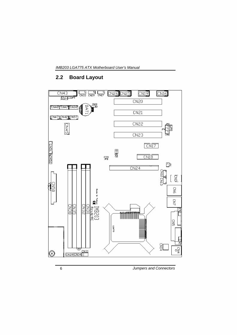
IMB203 LGA775 ATX Motherboard Userrsquos Manual
Jumpers and Connectors 6
22 Board Layout
IMB203 LGA775 ATX Motherboard Userrsquos Manual
Jumpers and Connectors 7
23 Jumper Settings Proper jumper settings configure the IMB203 to meet your application purpose
231 COM1 Mode Select Jumpers for RS-232422485 (JP1 JP3 JP4)
These jumpers select the COM1 portrsquos communication mode to operate RS-232 or RS-422485
Description Function Jumper Setting
RS-232 (Default)
JP1
JP3
JP4
RS-422 JP1 JP3
JP4
COM1
RS-485 JP1 JP3
JP4
IMB203 LGA775 ATX Motherboard Userrsquos Manual
Jumpers and Connectors 8
232 Audio Amplifier Jumper (JP2)
Description Function Jumper Setting
Disable
Audio Amplifier
Enable (Default)
IMB203 LGA775 ATX Motherboard Userrsquos Manual
Jumpers and Connectors 9
233 CMOS Clear Jumper (JP7) You may need to use this jumper is to clear the CMOS memory if incorrect BIOS settings
Description Function Jumper Setting
Normal (Default)
CMOS Clear
Clear CMOS
234 TPM DisableEnable Jumper (JP9)
Description Function Jumper Setting
Enable TPM (Default)
TPM Disable Enable
Disabled
IMB203 LGA775 ATX Motherboard Userrsquos Manual
Jumpers and Connectors 10
235 ME DisableEnable Jumper (JP10)
Description Function Jumper Setting
Enable (Default)
ME Disable Enable
Disable
刪除
IMB203 LGA775 ATX Motherboard Userrsquos Manual
Jumpers and Connectors 11
24 Connectors Connectors connect this board with other parts of the system Loose or improper connection might cause problems Make sure all connectors are properly and firmly connected
Label Connector
CN1 VGA
CN2 COM 1
CN3 Audio out Mic in
CN4 Keyboard Mouse
CN5 Print Port
CN6 CN7 USB Ports
CN14 ATX 2x2
CN16 COM 2
CN17 PCI Express x1 Slot
CN18 PCI Express x4 Slot
CN19 COM 3
CN25 COM 4
CN26 DIO
CN27 CN29 CN33 CN45 USB
CN31 FAN
CN36 CN37 CN41 CN42 CN46 CN47
SATA
CN50 ATX-24Pin
CN52 F_PANEL
IMB203 LGA775 ATX Motherboard Userrsquos Manual
Jumpers and Connectors 12
IMB203 LGA775 ATX Motherboard Userrsquos Manual
Jumpers and Connectors 13
241 VGA Connector (CN1) The board supports CRT VGA with a 15-pin D-Sub connector for the CRT VGA display
Pin Signal Pin Signal Pin Signal 1 Red 2 Green 3 Blue 4 NA 5 GND 6 GND 7 GND 8 GND 9 VCC 10 GND 11 NA 12 DDC DATA
13 Horizontal Sync 14 Vertical Sync 15 DDC CLK
242 COM1 Connector (CN2) The board has the onboard serial port COM1 (CN2) a 9-pin D-Sub connector on the rear IO to support RS-232422485 with jumper selectable RS-485 with auto-flow control
Pin Signal 1 DCD Data carrier detect 2 RXD Receive data 3 TXD Transmit data 4 DTR Data terminal ready 5 GND ground 6 DSR Data set ready 7 RTS Request to send 8 CTS Clear to send 9 RI Ring indicator
IMB203 LGA775 ATX Motherboard Userrsquos Manual
Jumpers and Connectors 14
243 COM2~COM4 Connectors (CN16 CN19 CN25) The board has the onboard serial ports COM2~4 (CN16 CN19 CN25) three 25-pin 254 pitch box-header to support RS-232
Pin Signal Pin Signal
1 Data Carrier Detect (DCD) 2 Data Set Ready
(DSR)
3 Receive Data (RXD) 4 Request to Send
(RTS)
5 Transmit Data (TXD) 6 Clear to Send
(CTS)
7 Data Terminal Ready (DTR) 8 Ring Indicator (RI)
9 Ground (GND) 10 NC
244 Audio Connector (CN3)
Color Signal
Green LINE_OUT
Red MIC_IN
IMB203 LGA775 ATX Motherboard Userrsquos Manual
Jumpers and Connectors 15
245 PS2 KeyboardMouse Connector (CN4) The board supports a keyboard and Mouse interface
Pin Signal Pin Signal
1 KB Data 7 MS Data
2 NC 8 NC
3 GND 9 GND
4 VCC 10 VCC
5 KB CLK 11 MS CLK
6 NC 12 NC
246 Print Port Connector (CN5)
Print Port Connector This board has a multi-mode parallel port to support the following modes 1 Standard Mode
IBM PCXT PCAT and PS2trade are compatible with bi-directional parallel port
2 Enhanced Mode Enhanced parallel port (EPP) is compatible with EPP 17 and EPP 19 (IEEE 1284 compliant)
3 High Speed Mode Microsoft and Hewlett Packard extended capabilities port (ECP) is IEEE 1284 compliant
Please refer to next page for the list of pin assignment
IMB203 LGA775 ATX Motherboard Userrsquos Manual
Jumpers and Connectors 16
Print Port Pin Assignment (Default)
Pin Signal 1 Data Carrier Detect (DCD) 2 Data Set Ready (DSR)
3 Receive Data (RXD)
4 Request to Send (RTS) 5 Transmit Data (TXD)
6 Clear to Send (CTS)
7 Data Terminal Ready (DTR) 8 Ring Indicator (RI)
9 Ground (GND)
247 USB Port Connector (CN6 CN7) The Universal Serial Bus (USB) port connector on the board is for the installation of peripherals supporting the USB interface The CN6CN7 consists of two 4-pin standard USB ports
Pin Signal
1 5 USB Vcc
2 6 USB -
3 7 USB +
4 8 USB GND
IMB203 LGA775 ATX Motherboard Userrsquos Manual
Jumpers and Connectors 17
248 USB Connectors (CN27 CN29 CN33 CN45) The 10-pin standard Universal Serial Bus (USB) connectors CN27293345 on this board are for installing versatile USB interface peripherals
Pin Signal Pin Signal 1 USB 2 USB
3 USB2- 4 USB3-
5 USB2+ 6 USB3+
7 GND 8 GND
9 GND 10 GND
CN45
Pin Signal Pin Signal 1 USB 2 USB
3 USB4- 4 USB5-
5 USB4+ 6 USB5+
7 GND 8 GND
10 GND
CN27 CN29 CN33
249 ATX 4 Pin 12V In Connector (CN14) You can connect it to the ATX12V power supply for CPU Core Voltage
Pin Signal 1 GND 2 GND 3 +12V 4 +12V
IMB203 LGA775 ATX Motherboard Userrsquos Manual
Jumpers and Connectors 18
2410 Digital IO Port (DIO) Connector (CN26) The board is equipped an 8-channel digital IO connector CN26 that meets requirements for a system customary automation control The digital IO can be configured to control cash drawers sense warning signals from an Uninterrupted Power System (UPS) or perform store security control The digital IO is controlled via software programming
Pin Signal Pin Signal
1 DO1 2 DI1
3 DO2 4 DI2
5 DO3 6 DI3
7 DO4 8 DI4
9 GND 10 GND
2411 CPU Fan Connector (CN31) A CPU fan is always needed for cooling CPU heat The CPU fan connector provides power to the CPU fan
Pin Signal 1 Ground 2 +12V 3 Rotation Detection4 Speed Control
2412 SATA Connectors (CN36 CN37 CN41 CN42
CN46 CN47) These SATA connectors are for high-speed SATA interface ports and they can be connected to hard disk devices
Pin Signal
1 GND
2 SATA_TX+
3 SATA_TX-
CN364146
IMB203 LGA775 ATX Motherboard Userrsquos Manual
Jumpers and Connectors 19
4 GND
5 SATA_RX-
6 SATA_RX+
7 GND
IMB203 LGA775 ATX Motherboard Userrsquos Manual
Jumpers and Connectors 20
2413 ATX Power Connector (CN50) Steady and sufficient power can be supplied to all components on the board by connecting the power connector Please make sure all components and devices are properly installed before connecting the power connector If you use a 24-pin ATX power supply please remove the small cover from the power connector before plugging in the power cord otherwise please do not remove it Pin Signal Pin Signal 1 33V 2 33V
3 GND 4 5V
5 GND 6 5V
7 GND 8 PWR
9 5VSB 10 12V
11 12V 12 33V
13 33V 14 -12V
15 GND 16 PS_ON
17 GND 18 GND
19 GND 20 -5V
21 5V 22 5V
23 5V 24 GND
IMB203 LGA775 ATX Motherboard Userrsquos Manual
Jumpers and Connectors 21
2414 Front Panel Connector (CN52)
Power LED
This 3-pin connector denoted as Pin 1 and Pin 5 connects the system power LED indicator to such a switch on the case Pin 1 is assigned as + and Pin 5 as - The Power LED lights up when the system is powered ON Pin 3 is defined as GND
External Speaker and Internal Buzzer Connector
Pin 2 4 6 and 8 can be connected to the case-mounted speaker unit or internal buzzer While connecting the CPU card to an internal buzzer please short pins 2-4 while connecting to an external speaker you need to set pins 2-4 to Open and connect the speaker cable to pin 8 (+) and pin 2 (-)
ATX Power OnOff Button
This 2-pin connector denoted as Pin 9 and 10 connects the front panelrsquos ATX power button to the CPU card which allows users to control ATX power supply to be power onoff
System Reset Switch
Pin 11 and 12 can be connected to the case-mounted reset switch that reboots your computer instead of turning OFF the power switch It is a better way to reboot your system for a longer life of the systemrsquos power supply
HDD Activity LED
This connection is linked to hard drive activity LED on the control panel LED flashes when HDD is being accessed Pin 13 and 14 connect the hard disk drive to the front panel HDD LED Pin 13 assigned as - and Pin 14 as +
IMB203 LGA775 ATX Motherboard Userrsquos Manual
Jumpers and Connectors 22
MEMO
IMB203 LGA775 ATX Motherboard Userrsquos Manual
Hardware Installation 23
CHAPTER 3 HARDWARE INSTALLATION
Before installing the processor please access Intelreg website for more detailed information httpwwwintelcom
31 Installing the Processor The LGA775 processor socket comes with a cover to protect the processor Please install the processor into the CPU socket step by step as below
Hold the hook (A) of the lever and push it down Pull the lever (B) aside to unlock the cover
IMB203 LGA775 ATX Motherboard Userrsquos Manual
Hardware Installation 24
Remove the plastic cap (E) from the cover
Open the cover (C) you can see the contact
Be careful not to touch the contact (D)
IMB203 LGA775 ATX Motherboard Userrsquos Manual
Hardware Installation 25
Place the CPU down into the socket Be careful not to touch the contact
Hold the edges of the CPU and orientate it as the marked direction (G) down into the socket to match the (H) and (F) locations
IMB203 LGA775 ATX Motherboard Userrsquos Manual
Hardware Installation 26
Slightly push down the cover and hook the lever (I~J) The CPU is completely locked
Orientate the CPU cooling fan to fixing holes on the board
IMB203 LGA775 ATX Motherboard Userrsquos Manual
Hardware Installation 27
Screw the CPU cooling fan onto the board
Make sure the CPU fan is plugged to the CPU fan connector
IMB203 LGA775 ATX Motherboard Userrsquos Manual
Hardware Installation 28
32 Installing the Memory The board supports four 240-pin DDR3 DIMM memory sockets with maximum memory capacity up to 16GB Please follow steps below to install the memory modules 1 Push down latches on each side of the DIMM socket 2 Align the memory module with the socket that notches of
memory module must match the socket keys for a correct installation
3 Install the memory module into the socket and push it firmly down until it is fully seated The socket latches are levered upwards and clipped on to the edges of the DIMM
4 Install any remaining DIMM modules
IMB203 LGA775 ATX Motherboard Userrsquos Manual
Hardware Description 29
CHAPTER 4 HARDWARE DESCRIPTION
41 Microprocessors The IMB203 Series supports Intelreg Coretrade 2 Quad Coretrade 2 Duo processors which make your system operated under Windowsreg XP and Linux environments The system performance depends on the microprocessor Make sure all correct settings are arranged for your installed microprocessor to prevent the CPU from damages
42 BIOS The IMB203 Series uses AMI Plug and Play BIOS with a single 32Mbit SPI Flash
43 System Memory The IMB203 Series supports four 240-pin DDR3 DIMM sockets for a maximum memory of 16GB DDR3 SDRAMs The memory module can come in sizes of 1GB 2GB and 4GB
IMB203 LGA775 ATX Motherboard Userrsquos Manual
Hardware Description 30
44 IO Port Address Map The Intelreg Coretrade 2 Extreme Intelreg Coretrade 2 Quad Coretrade 2 Duo CPUs can communicate via IO ports There are total 1KB port addresses available for assignment to other devices via IO expansion cards
Address Devices 000-01F DMA controller 1
020-02D 024-025 028-029 02C-02D Interrupt controller 1
02E-02F Forwarded to LPC(LPC Super IO ) 030-031 034-035 038-039 03C-03D
Interrupt controller 2
040-043 050-053 TimerCounter (8254) 060 Forwarded to LPC (Microcontroller) 061 NMI
062-066 Forwarded to LPC (Microcontroller) 070-077 Real time clock NMI 080-091 DMA page register
092 Processor IF(Reset Generator) 093-09F DMA page register 0A0-0BF Interrupt controller 2 0C0-0DF DMA controller 2
0F0 Processor IF 0F8-0FF Math processor 170-177 Forward to SATA (SATA Controller) 1F0-1F7 Forward to SATA (SATA Controller)
376 Forward to SATA(SATA Controller) 378-37F Parallel Port (LPT) 380-38F SDLC 2 3A0-3AF SDLC 1 3B0-3BF MDA video card
(to be continued)
IMB203 LGA775 ATX Motherboard Userrsquos Manual
Hardware Description 31
Address Devices 3C0-3CF EGA card 3D0-3DF CGA card
3F6 Forward to SATA(SATA Controller) 3F8-3FF Serial port 1 (COM1) 2F8-2FF Serial port 2 (COM2)
45 Interrupt Controller (IRQ) Map The IMB203 Series is a 100 PC compatible control board It consists of 16 interrupt request lines and four out of them can be programmable The mapping list of the 16 interrupt request lines is shown as the following table
IRQ Parity check error IRQ0 System Timer Output
IRQ1 Keyboard
IRQ2 Interrupt rerouting from IRQ8 through IRQ15
IRQ3 Serial port 2
IRQ4 Serial port 1
IRQ5 PCI Device Share
IRQ7 Parallel port
IRQ8 Real time clock
IRQ9 ACPI Controller
IRQ10 PCI Device Share
IRQ11 PCI Device Share
IRQ12 PS2 Mouse
IRQ13 Math coprocessor
IRQ14 SATA Primary (Legacy Mode)
IRQ15 SATA Secondary (Legacy Mode)
IMB203 LGA775 ATX Motherboard Userrsquos Manual
Hardware Description 32
MEMO
IMB203 LGA775 ATX Motherboard Userrsquos Manual
AMI BIOS Setup Utility 33
CHAPTER 5 AMI BIOS SETUP UTILITY
This chapter provides users with detailed description how to set up basic system configuration through the AMIBIOS8 BIOS setup utility 51 Starting To enter the setup screens follow the steps below 1 Turn on the computer and press the ltDelgt key immediately 2 After you press the ltDeletegt key the main BIOS setup menu
displays You can access the other setup screens from the main BIOS setup menu such as the Chipset and Power menus
52 Navigation Keys The BIOS setuputility uses a key-based navigation system called hot keys Most of the BIOS setup utility hot keys can be used at any time during the setup navigation process These keys include ltF1gt ltF10gt ltEntergt ltESCgt ltArrowgt keys and so on
Note Some of navigation keys differ from one screen to another
IMB203 LGA775 ATX Motherboard Userrsquos Manual
AMI BIOS Setup Utility 34
LeftRight The Left ltArrowgt keys allow you to select a setup screen
UpDown The Up and Down ltArrowgt keys allow you to select a setup screen or sub-screen
+minus PlusMinus The Plus and Minus ltArrowgt keys allow you to change the field value of a particular setup item
Tab The ltTabgt key allows you to select setup fields
F1 The ltF1gt key allows you to display the General Help screen
F10 The ltF10gt key allows you to save any changes you have made and exit Setup Press the ltF10gt key to save your changes
Esc
The ltEscgt key allows you to discard any changes you have made and exit the Setup Press the ltEscgt key to exit the setup without saving your changes
Enter
The ltEntergt key allows you to display or change the setup option listed for a particular setup item The ltEntergt key can also allow you to display the setup sub- screens
IMB203 LGA775 ATX Motherboard Userrsquos Manual
AMI BIOS Setup Utility 35
53 Main Menu When you first enter the Setup Utility you will enter the Main setup screen You can always return to the Main setup screen by selecting the Main tab There are two Main Setup options They are described in this section The Main BIOS Setup screen is shown below
System TimeDate
Use this option to change the system time and date Highlight System Time or System Date using the ltArrowgt keys Enter new values through the keyboard Press the ltTabgt key or the ltArrowgt keys to move between fields The date must be entered in MMDDYY format The time is entered in HHMMSS format
IMB203 LGA775 ATX Motherboard Userrsquos Manual
AMI BIOS Setup Utility 36
54 Advanced Menu The Advanced menu allows users to set configuration of the CPU and other system devices You can select any of the items in the left frame of the screen to go to the sub menus
CPU Configuration IDE Configuration SuperIO Configuration Hardware Health Configuration ACPI Configuration AHCI Configuration Intel iAMT Configuration Intel VT-d Configuration MPS Configuration PCI Express Configuration Trusted Computing USB Configuration
For items marked with ldquo rdquo please press ltEntergt for more options
IMB203 LGA775 ATX Motherboard Userrsquos Manual
AMI BIOS Setup Utility 37
CPU Configuration This screen shows the CPU Configuration and you can change the value of the selected option
Max CPUID Value Limit
You can enable this item to let legacy operating systems boot even without support for CPUs with extended CPU ID functions
Execute-Disable Bit Capability This item helps you enable or disable the No-Execution Page Protection Technology
Core Multi-Processing This feature controls the functionality of the Core Multi-Processing to allow the processor to execute multitasking function
PECI Use this item PECI (Platform Environment Control Interface) to execute the processor temperature monitoring and management
IMB203 LGA775 ATX Motherboard Userrsquos Manual
AMI BIOS Setup Utility 38
Intel (R) C-STATE tech Use this item to enable or disable the C-State technology
IDE Configuration You can use this screen to select options for the IDE Configuration and change the value of the selected option A description of the selected item appears on the right side of the screen For items marked with ldquo rdquo please press ltEntergt for more options
SATA1 Configuration
Use this item to control the onboard SATA controller Here are the options for your selection Compatible Disabled and Enhanced
Configure SATA1 as Use this item to choose the SATA operation mode Here are the options for your selection IDE and AHCI
SATA2 Configuration Use this item to control the onboard SATA controller Here are the options for your selection Enhanced and Disabled
IMB203 LGA775 ATX Motherboard Userrsquos Manual
AMI BIOS Setup Utility 39
PrimarySecondaryThird IDE Master Select one of the hard disk drives to configure IDE devices installed in the system by pressing ltEntergt for more options
Fifth IDE Master Select one of the hard disk drives to configure IDE devices installed in the system by pressing ltEntergt for more options
IMB203 LGA775 ATX Motherboard Userrsquos Manual
AMI BIOS Setup Utility 40
SuperIO Configuration You can use this screen to select options for the SuperIO Configuration and change the value of the selected option A description of the selected item appears on the right side of the screen
Serial Port1 Address
This option specifies the base IO port address and Interrupt Request address of serial port 1 The Optimal setting is 3F8IRQ4 The Fail-Safe default setting is Disabled
Serial Port2 Address This option specifies the base IO port address and Interrupt Request address of serial port 2 The Optimal setting is 2F8IRQ3 The Fail-Safe setting is Disabled
Parallel Port Address This item allows you to determine the IO address for onboard parallel port There are several options for your selection
Parallel Port Mode
IMB203 LGA775 ATX Motherboard Userrsquos Manual
AMI BIOS Setup Utility 41
Select an operating mode for the onboard parallel (printer) port
Parallel Port IRQ Use this item to set up the IRQ for onboard parallel port
Serial Port3 Address This item specifies the base IO port address and Interrupt Request address of serial port 3 The Optimal setting is 3E8IRQ11 The Fail-Safe default setting is Disabled
Serial Port3 IRQ This item specifies the IRQ used by the serial port 3
Serial Port4 Address This item specifies the base IO port address and Interrupt Request address of serial port 4 The Optimal setting is 2E8IRQ10 The Fail-Safe default setting is Disabled
Serial Port4 IRQ This item specifies the IRQ used by the serial port 4
IMB203 LGA775 ATX Motherboard Userrsquos Manual
AMI BIOS Setup Utility 42
Hardware Health Configuration This screen shows the Hardware Health Configuration and a description of the selected item appears on the right side of the screen
HW Health Configuration
This screen displays the temperature of CPU and System Fan Speed Vcore etc
IMB203 LGA775 ATX Motherboard Userrsquos Manual
AMI BIOS Setup Utility 43
ACPI Configuration You can use this screen to select options for the ACPI Configuration and change the value of the selected option A description of the selected item appears on the right side of the screen
General ACPI Configuration
Scroll to this item and press ltEntergt to view the General ACPI Configuration sub menu which contains General ACPI (Advanced Configuration and Power Management Interface) options for your configuration
Advanced ACPI Configuration Scroll to this item and press ltEntergt to view the Advanced ACPI Configuration sub menu which contains Advanced ACPI (Advanced Configuration and Power Management Interface) options for your configuration
Chipset ACPI Configuration Scroll to this item and press ltEntergt to view the Chipset ACPI Configuration sub menu which contains Chipset ACPI (Advanced Configuration and Power Management
IMB203 LGA775 ATX Motherboard Userrsquos Manual
AMI BIOS Setup Utility 44
Interface) options for your configuration AHCI Configuration
You can use this screen to select options for the AHCI Configuration and change the value of the selected option A description of the selected item appears on the right side of the screen
AHCI BIOS Support You can enable or disable this item to control the AHCI function of the SATA controller
IMB203 LGA775 ATX Motherboard Userrsquos Manual
AMI BIOS Setup Utility 45
Intel iAMT Configuration You can use this screen to select options for the Intel iAMT Configuration and change the value of the selected option A description of the selected item appears on the right side of the screen
Intel iAMT Support
You can enable this item to support iAMT (active management technology) function to follow up the procedure for the access to AMI program screen
Unconfigure iAMTME Use this item to unconfigure the iAMTME settings
IMB203 LGA775 ATX Motherboard Userrsquos Manual
AMI BIOS Setup Utility 46
Intel VT-d Configuration You can use this screen to select options for the Intel VT-d Configuration and change the value of the selected option A description of the selected item appears on the right side of the screen
Intel VT-d Virtualization Technology for Directed IO (VT-d) extends Virtualization Technology (VT) roadmap by providing hardware assists for virtualization solution VT-d can help end users improve security and reliability of the systems and also improve performance of IO devices in virtualized environment Here are the options for your selection Disabled and Enabled
IMB203 LGA775 ATX Motherboard Userrsquos Manual
AMI BIOS Setup Utility 47
Remote Access Configuration You can use this screen to select options for the Remote Access Configuration and change the value of the selected option A description of the selected item appears on the right side of the screen
Remote Access Use this item to enable or disable the Remote Access function
IMB203 LGA775 ATX Motherboard Userrsquos Manual
AMI BIOS Setup Utility 48
PCI Express Configuration This screen shows the PCI Express Configuration and you can change its value A description of the selected item appears on the right side of the screen
Active State Power-Management
Use this item to enable or disable the function of Active State Power-Management to provide you with lower power consumption The default setting is Disabled
IMB203 LGA775 ATX Motherboard Userrsquos Manual
AMI BIOS Setup Utility 49
Trusted Computing You can use this screen to select options for the Trusted Computing and change the value of the selected option A description of the selected item appears on the right side of the screen
TCGTPM SUPPORT Use this item to control the Trusted Platform Module (TPM) function
IMB203 LGA775 ATX Motherboard Userrsquos Manual
AMI BIOS Setup Utility 50
USB Configuration You can use this screen to select options for the USB Configuration and change the value of the selected option A description of the selected item appears on the right side of the screen
USB Functions
This item allows you to enable or disable USB functions
Legacy USB Support Use this item to enable or disable support for USB device on legacy operating system The default setting is Enabled
USB 20 Controller Mode Use this item to configure the USB 20 controller The default setting is HiSpeed
BIOS EHCI Hand-Off Enabling this item provide the support for operating systems without an EHCI hand-off feature The default setting is Enabled
IMB203 LGA775 ATX Motherboard Userrsquos Manual
AMI BIOS Setup Utility 51
IMB203 LGA775 ATX Motherboard Userrsquos Manual
AMI BIOS Setup Utility 52
55 PCI PnP Menu The PCI PnP menu allows users to change the advanced settings for PCIPnP devices
Clear NVRAM
Use this item to clear the data in the NVRAM (CMOS) Here are the options for your selection No and Yes
Plug amp Play OS When the setting is No Use this item to configure all the devices in the system When the setting is Yes and if you install a Plug and Play operating system the operating system configures the Plug and Play devices not required for boot The default setting is No
IMB203 LGA775 ATX Motherboard Userrsquos Manual
AMI BIOS Setup Utility 53
PCI Latency Timer This item controls how long a PCI device can hold the PCI bus before another takes over The longer the latency the longer the PCI device can retain control of the bus before handing it over to another PCI device There are several options for your selection
Allocate IRQ to PCI VGA This item allows BIOS to choose an IRQ to assign for the PCI VGA card Here are the options for your selection No and Yes
Palette Snooping Some old graphic controllers need to ldquosnooprdquo on the VGA palette and then map it to their display as a way to provide boot information and VGA compatibility This item allows such snooping to take place Here are the options for your selection Disabled and Enabled
PCI IDE BusMaster This item is a toggle for the built-in driver that allows the onboard IDE controller to perform DMA (Direct Memory Access) transfer Here are the options for your selection Disabled and Enabled
OffBoard PCIISA IDE Card This item is for any other non-onboard PCIISA IDE controller adapter There are several options for your selection
IRQ3457910111415 These items will allow you to assign each system interrupt a type depending on the type of device using the interrupt The option ldquoAvailablerdquo means the IRQ is going to assign automatically Here are the options for your selection Available and Reserved
DMA Channel 013567 These items will allow you to assign each DMA channel a type depending on the type of device using the channel The option ldquoAvailablerdquo means the channel is going to assign automatically Here are the options for your selection Available and Reserved
IMB203 LGA775 ATX Motherboard Userrsquos Manual
AMI BIOS Setup Utility 54
56 Boot Menu The Boot menu allows users to change boot options of the system You can select any of the items in the left frame of the screen to go to the sub menus
Boot Settings Configuration Boot Device Priority Removable Drives
For items marked with ldquo rdquo please press ltEntergt for more options
IMB203 LGA775 ATX Motherboard Userrsquos Manual
AMI BIOS Setup Utility 55
Boot Settings Configuration
Quick Boot
Enabling this item lets the BIOS skip some power on self tests (POST) The default setting is Enabled
AddOn ROM Display Mode This item selects the display mode for option ROM The default setting is Force BIOS
Boot Num-Lock Use this item to select the power-on state for the NumLock The default setting is On
PS2 Mouse Support This item determines if the BIOS should reserve IRQ12 for the PS2 mouse or allow other devices to make use of this IRQ Here are the options for your selection Auto Enabled and Disabled
Wait For lsquoF1rsquo Of Error If this item is enabled the system waits for the F1 key to be pressed when error occurs The default setting is Enabled
Hit lsquoDELrsquo Message Display If this item is enabled the system displays the message
IMB203 LGA775 ATX Motherboard Userrsquos Manual
AMI BIOS Setup Utility 56
ldquoPress DEL to run Setuprdquo during POST The default setting is Enabled
Interrupt 19 Capture If this item is enabled this function makes the option ROMs to trap Interrupt 19 The default setting is Disabled
Boot Device Priority The Boot Device Priority screen specifies the boot device priority sequence from the available devices
IMB203 LGA775 ATX Motherboard Userrsquos Manual
AMI BIOS Setup Utility 57
Removable Drives Use this screen to view the removable drives in the system The BIOS will attempt to arrange the removable drive boot sequence automatically You can also change the booting sequence
IMB203 LGA775 ATX Motherboard Userrsquos Manual
AMI BIOS Setup Utility 58
57 Security Menu The Security menu allows users to change the security settings for the system
Supervisor Password
This item indicates whether a supervisor password has been set If the password has been installed Installed displays If not Not Installed displays
User Password This item indicates whether a user password has been set If the password has been installed Installed displays If not Not Installed displays
Change Supervisor Password Select this option and press ltEntergt to access the sub menu You can use the sub menu to change the supervisor password
Change User Password Select this option and press ltEntergt to access the sub menu You can use the sub menu to change the user password
IMB203 LGA775 ATX Motherboard Userrsquos Manual
AMI BIOS Setup Utility 59
58 Chipset Menu The Chipset menu allows users to change the advanced chipset settings You can select any of the items in the left frame of the screen to go to the sub menus
North Bridge Configuration South Bridge Configuration ME Subsystem Configuration
For items marked with ldquo rdquo please press ltEntergt for more options
IMB203 LGA775 ATX Motherboard Userrsquos Manual
AMI BIOS Setup Utility 60
North Bridge Configuration
Memory Remap Feature
Use this item to enable or disable the remapping of the overlapped PCI memory above the total physical memory Only 64-bit OS supports this function
DRAM Frequency This item allows you to control the Memory Clock
Configure DRAM Timing by SPD This item can enable or disable DRAM timing by SPD (Serial Presence Detect) device which is a small EEPROM chip on the memory module containing important information about the module speed size addressing mode and various parameters
Memory Hole You can reserve this area of system memory for ISA adapter ROM When this area is reserved it cannot be cached Check the user information of peripherals that need to use this area o f system memory for the memory requirements Here are the options Disabled and 15M-16M
IMB203 LGA775 ATX Motherboard Userrsquos Manual
AMI BIOS Setup Utility 61
Initiate Graphic Adapter When using multiple graphics cards this item can select which graphics controller to be the primary display device during boot
IGD Graphics Mode Select This item allows you to select the amount of system memory used by the internal graphics device
PEG Port ConfigurationPEG Port This item is a toggle to enable or disable the PCI Express port Here are the options for your selection Auto and Disabled
Video Function Configuration Press ltEntergt for the sub-menu for setting up video function
IMB203 LGA775 ATX Motherboard Userrsquos Manual
AMI BIOS Setup Utility 62
South Bridge Configuration
GbE Wake Up From S5 This item specifies whether the system will be awakened from the S5 power
HDA Controller This item allows you to enable or disable the HD audio support
Restore on AC Power Loss This item can control how the PC will behave once power is restored following a power outage or other unexpected shutdown
PCIE Port Configuration This item allows you to set or disable the PCI Express Ports
IMB203 LGA775 ATX Motherboard Userrsquos Manual
AMI BIOS Setup Utility 63
ME Subsystem Configuration
It is strongly recommended that you do not modify these options unless you are an advanced user
IMB203 LGA775 ATX Motherboard Userrsquos Manual
AMI BIOS Setup Utility 64
59 Exit Menu The Exit menu allows users to load your system configuration with optimal or failsafe default values
Save Changes and Exit
When you have completed the system configuration changes select this option to leave Setup and reboot the computer so the new system configuration parameters can take effect Select Save Changes and Exit from the Exit menu and press ltEntergt Select Ok to save changes and exit
Discard Changes and Exit Select this option to quit Setup without making any permanent changes to the system configuration Select Discard Changes and Exit from the Exit menu and press ltEntergt Select Ok to discard changes and exit
Load Optimal Defaults It automatically sets all Setup options to a complete set of default settings when you select this option The Optimal settings are designed for maximum system performance but may not work best for all computer applications In particular do not use the Optimal Setup options if your
IMB203 LGA775 ATX Motherboard Userrsquos Manual
AMI BIOS Setup Utility 65
computer is experiencing system configuration problems Select Load Optimal Defaults from the Exit menu and press ltEntergt
Load Fail-Safe Defaults It automatically sets all Setup options to a complete set of default settings when you select this option The Fail-Safe settings are designed for maximum system stability but not maximum performance Select the Fail-Safe Setup options if your computer is experiencing system configuration problems Select Load Fail-Safe Defaults from the Exit menu and press ltEntergt Select Ok to load Fail-Safe defaults
IMB203 LGA775 ATX Motherboard Userrsquos Manual
AMI BIOS Setup Utility 66
MEMO
IMB203 LGA775 ATX Motherboard Userrsquos Manual
Installation of Drivers 67
CHPATER 6 INSTALLATION OF DRIVERS
The device drivers are located on the Product Information CD-ROM that comes with the IMB203 Series package The auto-run function of drivers will guide you to install the utilities and device drivers under a Windows system You can follow the onscreen instructions to install these devices
Chipse VGA LAN Audio iAMT MEI
61 Installing Chipset Driver 1 Run the SETUPEXE program from the driver directory in
your driver CD Click ldquoNextrdquo to next step
IMB203 LGA775 ATX Motherboard Userrsquos Manual
Installation of Drivers 68
2 An Intelreg License Agreement appears to show you the important information Click ldquoYesrdquo to next step
3 Refer to the Readme file below to view the system requirements and installation information
IMB203 LGA775 ATX Motherboard Userrsquos Manual
Installation of Drivers 69
3-1 Please wait while running the following setup operations
3-2 Please wait while running the following setup operations
IMB203 LGA775 ATX Motherboard Userrsquos Manual
Installation of Drivers 70
4 Click ldquoFinishrdquo to complete the setup process
5 You will be asked to reboot your computer when the installation is completed Please click ldquoYes I want to restart my computer nowrdquo if you donrsquot need to install any other drivers Otherwise please click ldquoNo I will restart my computer laterrdquo and go on next step
IMB203 LGA775 ATX Motherboard Userrsquos Manual
Installation of Drivers 71
62 Installing VGA Driver 1 Run the SETUPEXE program from the driver directory in
your driver CD Click ldquoNextrdquo to next step
2 An Intelreg License Agreement appears to show you the
important information Click ldquoYesrdquo to next step
IMB203 LGA775 ATX Motherboard Userrsquos Manual
Installation of Drivers 72
3 The message of Readme File Information appears to show you the system requirements and installation information Please click ldquoNextrdquo
4 Please wait while running the following setup operations
When this message appears please click ldquoNextrdquo
IMB203 LGA775 ATX Motherboard Userrsquos Manual
Installation of Drivers 73
5 Click ldquoFinishrdquo to complete the setup process
6 You will be asked to reboot your computer when the installation is completed Please click ldquoYes I want to restart my computer nowrdquo if you donrsquot need to install any other drivers Otherwise please click ldquoNo I will restart my computer laterrdquo and click ldquoFinishrdquo to complete the installation
IMB203 LGA775 ATX Motherboard Userrsquos Manual
Installation of Drivers 74
63 Installing LAN Driver
11 Run the InstallShield Wizard for Network Connections from
the driver directory in your driver CD Click ldquoNextrdquo to next step
IMB203 LGA775 ATX Motherboard Userrsquos Manual
Installation of Drivers 75
12 An Intelreg License Agreement appears to show you the important information Click ldquoYesrdquo to next step
13 A Setup Options window appears that you can select the
program features you want to install
IMB203 LGA775 ATX Motherboard Userrsquos Manual
Installation of Drivers 76
2 Click ldquoInstallrdquo to start the installation
3 Please wait while running the following installation operation
IMB203 LGA775 ATX Motherboard Userrsquos Manual
Installation of Drivers 77
4 Click ldquoFinishrdquo to complete the installation
Note The Driver item [Wake on Directed Packet] default is Enabled under Windows Vista
格式化 字型 (符號) Arial
格式化 字型 (符號) Arial
格式化 字型 斜體 字型色彩 黑色 (符號) Arial 非加寬 緊縮
格式化 字型 斜體 字型色彩 黑色 (符號) Arial 非加寬 緊縮
格式化 字型 (符號) Arial 非加寬 緊縮
IMB203 LGA775 ATX Motherboard Userrsquos Manual
Installation of Drivers 78
64 Installing AUDIO Driver 1 Run the InstallShield Wizard for Realtek High Definition
Audio Driver from the driver directory in your driver CD Click ldquoNextrdquo to next step
IMB203 LGA775 ATX Motherboard Userrsquos Manual
Installation of Drivers 79
2 Click ldquoInstallrdquo to start the installation and wait while running the installation operation
3 Click ldquoFinishrdquo to complete the installation
IMB203 LGA775 ATX Motherboard Userrsquos Manual
Installation of Drivers 80
65 Installing iAMT (Active Management Technology) Driver
Note You must download and properly install the required NET version 35 provided from a separate downloading of the actual FimwareTools kit releases posted on VIP prior to loading the MEILMS Driver stack
651 LMS_SOL Setup
1 Run the setup program to install Intelreg Active Management Technology onto your computer It is strongly recommended that you exit all programs before continuing Click ldquoNextrdquo to next step
格式化 字型 (符號) Arial
格式化 字型 (符號) Arial 非加寬 緊縮
IMB203 LGA775 ATX Motherboard Userrsquos Manual
Installation of Drivers 81
2 An Intelreg license agreement appears that you need to continue the setup program by clicking ldquoYesrdquo to accept the terms
IMB203 LGA775 ATX Motherboard Userrsquos Manual
Installation of Drivers 82
3 Refer to the Readme file below to view the system requirements and installation information Click ldquoNextrdquo to next setup
4 Please wait while running the following installation operation
IMB203 LGA775 ATX Motherboard Userrsquos Manual
Installation of Drivers 83
5 Click ldquoFinishrdquo to complete the installation
IMB203 LGA775 ATX Motherboard Userrsquos Manual
Installation of Drivers 84
652 LMS_SOL_IS Setup
1 Run the setup program to install Intelreg Active Management Technology onto your computer It is strongly recommended that you exit all programs before continuing Click ldquoNextrdquo to next step
IMB203 LGA775 ATX Motherboard Userrsquos Manual
Installation of Drivers 85
2 An Intelreg license agreement appears that you need to continue the setup program by clicking ldquoYesrdquo to accept the terms
IMB203 LGA775 ATX Motherboard Userrsquos Manual
Installation of Drivers 86
3 Refer to the Readme file below to view the system requirements and installation information Click ldquoNextrdquo to next setup
4 Please wait while running the following installation operation
IMB203 LGA775 ATX Motherboard Userrsquos Manual
Installation of Drivers 87
5 Click ldquoFinishrdquo to complete the installation
IMB203 LGA775 ATX Motherboard Userrsquos Manual
Installation of Drivers 88
66 Installing MEI (Management Engine Interface) Driver
Note You must download and properly install the required NET version 35 provided from a separate downloading of the actual FimwareTools kit releases posted on VIP prior to loading the MEILMS Driver stack
1 Run the setup program to install Intelreg Management Engine
Interface onto your computer It is strongly recommended that you exit all programs before continuing Click ldquoNextrdquo to next step
格式化 字型 (符號) Arial
格式化 字型 (符號) Arial 非加寬 緊縮
IMB203 LGA775 ATX Motherboard Userrsquos Manual
Installation of Drivers 89
2 An Intelreg license agreement appears that you need to continue the setup program by clicking ldquoYesrdquo to accept the terms
IMB203 LGA775 ATX Motherboard Userrsquos Manual
Installation of Drivers 90
3 Refer to the Readme file below to view the system requirements and installation information Click ldquoNextrdquo to next setup
4 Please wait while running the following installation operation
IMB203 LGA775 ATX Motherboard Userrsquos Manual
Installation of Drivers 91
5 Click ldquoFinishrdquo to complete the installation
IMB203 LGA775 ATX Motherboard Userrsquos Manual
Installation of Drivers 92
MEMO
IMB203 LGA775 ATX Motherboard Userrsquos Manual
Watchdog Timer 93
APPENDIX A WATCHDOG TIMER
Watchdog Timer Setting After the system stops working for a while it can be auto-reset by the Watchdog Timer The integrated Watchdog Timer can be set up in the system reset mode by program
Using the Watchdog Function Start darr Un-Lock WDT O 2E 87 Un-lock super IO
O 2E 87 Un-lock super IO darr Set WDT Function O 2E 2D O 2F 20 Select Logic device O 2E 07 O 2F 08 darr Activate WDT O 2E 30
O 2F 01 Set Second or Minute O 2E F5
O 2F N N=00 or 08(See below table) darr Set base timer O 2E F6
O 2F M=000102hellipFF(Hex) Value=0 to 255 darr WDT counting
re-set timer O 2E F6
O 2F M M=000102hellipFF(See below table) darr
格式化
格式化 項目符號及編號
格式化 項目符號及編號
格式化 字型 8 點 字型色彩黑色
格式化 字型 8 點 字型色彩黑色
格式化 定位點 1257 字元左 + 不在 1012 字元 + 1386字元
格式化 字型 8 點 字型色彩黑色
格式化 定位點 1257 字元左 + 不在 134 字元 + 1362字元
格式化 字型色彩 黑色
格式化 字型色彩 黑色
刪除
IMB203 LGA775 ATX Motherboard Userrsquos Manual
Watchdog Timer 94
IF No re-set timer WDT time-out generate RESET IF to disable WDT O 2E 30
O 2F 00 Can be disable at any time
N=00
M= 00h Time-out Disable 01h Time-out occurs after 1 second 02h Time-out occurs after 2 second 03h Time-out occurs after 3 second helliphelliphelliphelliphelliphelliphelliphelliphellip FFh Time-out occurs after 255 second
N=08
M= 00h Time-out Disable 01h Time-out occurs after 1 minute 02h Time-out occurs after 2 minutes 03h Time-out occurs after 3 minutes helliphelliphelliphelliphelliphelliphelliphelliphellip
FFh Time-out occurs after 255 minutes
格式化 字型色彩 黑色
格式化 字型色彩 黑色
IMB203 LGA775 ATX Motherboard Userrsquos Manual
PCI IRQ Routing 95
APPENDIX B PCI IRQ ROUTING
PICMG PCI IRQ Routing
Device ID Slot Int
PCI Slot 0 31 0 BCDA PCI Slot 1 30 1 CDAB PCI Slot 2 29 2 DABC PCI Slot 3 28 3 ABCD
IMB203 LGA775 ATX Motherboard Userrsquos Manual
PCI IRQ Routing 96
MEMO
IMB203 LGA775 ATX Motherboard Userrsquos Manual
Configuring SATA for RAID Function 97
APPENDIX C CONFIGURING SATA FOR RAID
FUNCTION
Configuring SATA Hard Drive(s) for RAID Function (Controller IntelregICH10DODO DH only) Please follow up the steps below to configure SATA hard drive(s) (1) Install SATA hard drive(s) in your system (2) Enter the BIOS Setup to configure SATA controller mode and boot
sequence (3) Configure RAID by the RAID BIOS (4) Install the SATA controller driver during the OS installation Before you begin the SATA configuration please prepare (a) Two SATA hard drives (to ensure optimal performance it is
recommended that you use two hard drives with identical model and capacity) If you do not want to create RAID with the SATA controller you may prepare only one hard drive
(b) An empty formatted floppy disk (c) Windows XP setup disk (1) Installing SATA hard drive(s) in your system
Connect one end of the SATA signal cable to the rear of the SATA hard drive and the other end to available SATA port(s) on the board Then connect the power connector of power supply to the hard drive
(2) Configuring SATA controller mode and boot sequence by the BIOS Setup You have to make sure whether the SATA controller is configured correctly by system BIOS Setup and set up BIOS boot sequence for the SATA hard drive(s)
IMB203 LGA775 ATX Motherboard Userrsquos Manual
Configuring SATA for RAID Function 98
(2)-1-1 Turn on your system and then press the Del button to enter BIOS Setup during running POST (Power-On Self Test) If you want to create RAID just go to the Advanced Settings menuIDE configuration select the Configure SATA1 as and press ltEntergt for more options
IMB203 LGA775 ATX Motherboard Userrsquos Manual
Configuring SATA for RAID Function 99
(2)-1-2 A list of options appears please select RAID
IMB203 LGA775 ATX Motherboard Userrsquos Manual
Configuring SATA for RAID Function 100
(2)-2 Set CDROM for First Boot Device under the Boot Settings menu to boot CD-ROM after system restarts
(2)-3 Save and exit the BIOS Setup
IMB203 LGA775 ATX Motherboard Userrsquos Manual
Configuring SATA for RAID Function 101
(3) Configuring RAID by the RAID BIOS Enter the RAID BIOS setup utility to configure a RAID array Skip this step and proceed to Section 4 if you do not want to create a RAID (3)-1 After the POST memory testing and before the operating
system booting a message Press ltCtrl-Igt to enter Configuration Utility shows up accordingly press ltCTRL+ Igt to enter the RAID BIOS setup utility
(3)-2 After you press ltCTRL+ Igt the Create RAID Volume screen will appear If you want to create a RAID array select the Create RAID Volume option in the Main Menu and press ENTER
IMB203 LGA775 ATX Motherboard Userrsquos Manual
Configuring SATA for RAID Function 102
(3)-3-1 After entering the CREATE VOLUME MENU screen you can type the disk array name with 1~16 letters (letters cannot be special characters) in the item ldquoNamerdquo
(3)-3-2 When finished press ENTER to select a RAID level There are three RAID levels RAID0 RAID1 and RAID5 amp RAID10 Select a RAID level and press ENTER
IMB203 LGA775 ATX Motherboard Userrsquos Manual
Configuring SATA for RAID Function 103
(3)-4 Set the stripe block size The KB is the standard unit of stripe block size The stripe block size can be 4KB to 128KB After the setting press ENTER for the array capacity
(3)-5 After setting all the items on the menu select Create Volume
and press ENTER to start creating the RAID array
IMB203 LGA775 ATX Motherboard Userrsquos Manual
Configuring SATA for RAID Function 104
(3)-6 When prompting the confirmation press ldquoYldquo to create this volume or ldquoNldquo to cancel the creation
After the creation is completed you can see detailed information about the RAID Array in the DISKVOLUME INFORMATION section including RAID mode disk block size disk name and disk capacity etc
IMB203 LGA775 ATX Motherboard Userrsquos Manual
Configuring SATA for RAID Function 105
Delete RAID Volume If you want to delete a RAID volume select the Delete RAID Volume option in Main Menu Press ENTER and follow on-screen instructions
Please press [ESC] to exit the RAID BIOS utility Now you can proceed to install a SATA driver controller and the operating system
IMB203 LGA775 ATX Motherboard Userrsquos Manual
Configuring SATA for RAID Function 106
(4) Making a SATA Driver Disk To install the operating system onto a serial ATA hard disk successfully you need to install the SATA controller driver during the OS installation Without the driver the hard disk may not be recognized during the Windows setup process First of all please format a blank floppy disk Secondly follow up these steps below to produce a SATA driver disk Users can insert the Driver CD and the formatted blank floppy disk in another system And then please copy all of file of the f6flpy32 folder in the Driver CD to a floppy disk Note Please copy all of file of the f6flpy64 folder if installing 64-bit
Windows Operating System
IMB203 LGA775 ATX Motherboard Userrsquos Manual
Configuring SATA for RAID Function 107
(5) Installing the SATA controller driver during the OS installation Now the SATA driver disk is ready and BIOS settings configured you can proceed to install Windows 2000XP onto your SATA hard drive using the SATA driver Here is an example for Windows XP installation (5)-1 Restart your system to boot the Windows 2000XP Setup disk
and press F6 button as soon as you see the message Press F6 if you need to install a 3rd party SCSI or RAID driver After pressing the F6 button there will be a few moments for some files being loaded before next screen appears
IMB203 LGA775 ATX Motherboard Userrsquos Manual
Configuring SATA for RAID Function 108
(5)-2 When you see the screen below insert the floppy disk containing the SATA driver and press ldquoSrdquo
(5)-3 If the Setup correctly recognizes the driver of the floppy disk
a controller menu will appear below Use the ARROW keys to select Intel(R) ICH8RICH9RICH10RDO SATA RAID Controller and press ENTER Then it will begin to load the SATA driver from the floppy disk
IMB203 LGA775 ATX Motherboard Userrsquos Manual
Configuring SATA for RAID Function 109
Note If a message on the screen saying that one or some file(s) cannot be found please check the floppy disk or copy the correct SATA driver again from the driver CD
IMB203 LGA775 ATX Motherboard Userrsquos Manual
Configuring SATA for RAID Function 110
MEMO
IMB203 LGA775 ATX Motherboard Userrsquos Manual
iAMT Settings 111
APPENDIX D iAMT SETTINGS
The Intelreg Active Management Technology (Intelreg iAMT) has decreased a major barrier to IT efficiency that uses built-in platform capabilities and popular third-party management and security applications to allow IT a better discovering healing and protection their networked computing assets In order to utilize Intel iAMT you must enter the ME BIOS (CTRL + P during system startup) change the ME BIOS password and then select ldquoIntelreg iAMTrdquo as the manageability feature
D1 Entering MEBx 1 You must go to BIOS TO start iAMT function 2 Exit from BIOS after starting iAMT and press Ctrl+P to enter MEBx Setting
It is better to press Ctrl+P before the screen popping out
格式化
IMB203 LGA775 ATX Motherboard Userrsquos Manual
iAMT Settings 112
D2 Set amp Change Password 1 You will be asked to set a password when first log in The default
password is lsquoadminrsquo
2 You will be asked to change the password before setting ME
Change Password
IMB203 LGA775 ATX Motherboard Userrsquos Manual
iAMT Settings 113
3 You must confirm your new password while revising (as Remark 1)
Remark 1 The new password must contain (example 11qqQQ) (default value)
Eight characters
One upper case
One lower case
One number
One special symbol such as $ or
( excepted)
Underline ( _ ) and space are valid characters for password but they wonrsquot make higher complexity
IMB203 LGA775 ATX Motherboard Userrsquos Manual
iAMT Settings 114
D3 Intelreg iAMT Settings 1 Select Intelreg iAMT Configuration and press ltENTERgt
2 Key in the Host Name If Intelreg iAMT set to lsquoDHCPlsquo the Host name must be identical to the operating system mechanic
IMB203 LGA775 ATX Motherboard Userrsquos Manual
iAMT Settings 115
3 Select TCPIP to get into Network interface and set it to lsquoENABLEDrsquo into DHCP Mode and set it to lsquoDISABLEDrsquo (as Remark 2) into Domain name and set the Intel Management Engine domain name such as lsquoAMTintelcomrsquo
(3-1)
(3-2)
IMB203 LGA775 ATX Motherboard Userrsquos Manual
iAMT Settings 116
Remark 2 DHCP Mode lsquoDISABLEDlsquo if DHCP Mode is disabled you can make the following settings
IP address
Subnet mask
IMB203 LGA775 ATX Motherboard Userrsquos Manual
iAMT Settings 117
Default Gateway address
Preferred DNS address
IMB203 LGA775 ATX Motherboard Userrsquos Manual
iAMT Settings 118
Alternate DNS address
Domain name
4 Exit from MEBx after completing the iAMT settings
IMB203 LGA775 ATX Motherboard Userrsquos Manual
iAMT Settings 119
D4 iAMT Web Console 1 From a web browser please type http(IP ADDRESS)16992
which connects to iAMT Web Example http1014021416992
2 To log on you will be required to type in username and password
for access to the Web
USER admin (default value)
PASS (MEBx password)
IMB203 LGA775 ATX Motherboard Userrsquos Manual
iAMT Settings 120
3 Enter the iAMT Web
4 Click Remote Control and select commands on the right side
IMB203 LGA775 ATX Motherboard Userrsquos Manual
iAMT Settings 121
5 When you have finished using the iAMT Web console close the Web browser
IMB203 LGA775 ATX Motherboard Userrsquos Manual
iAMT Settings 122
MEMO
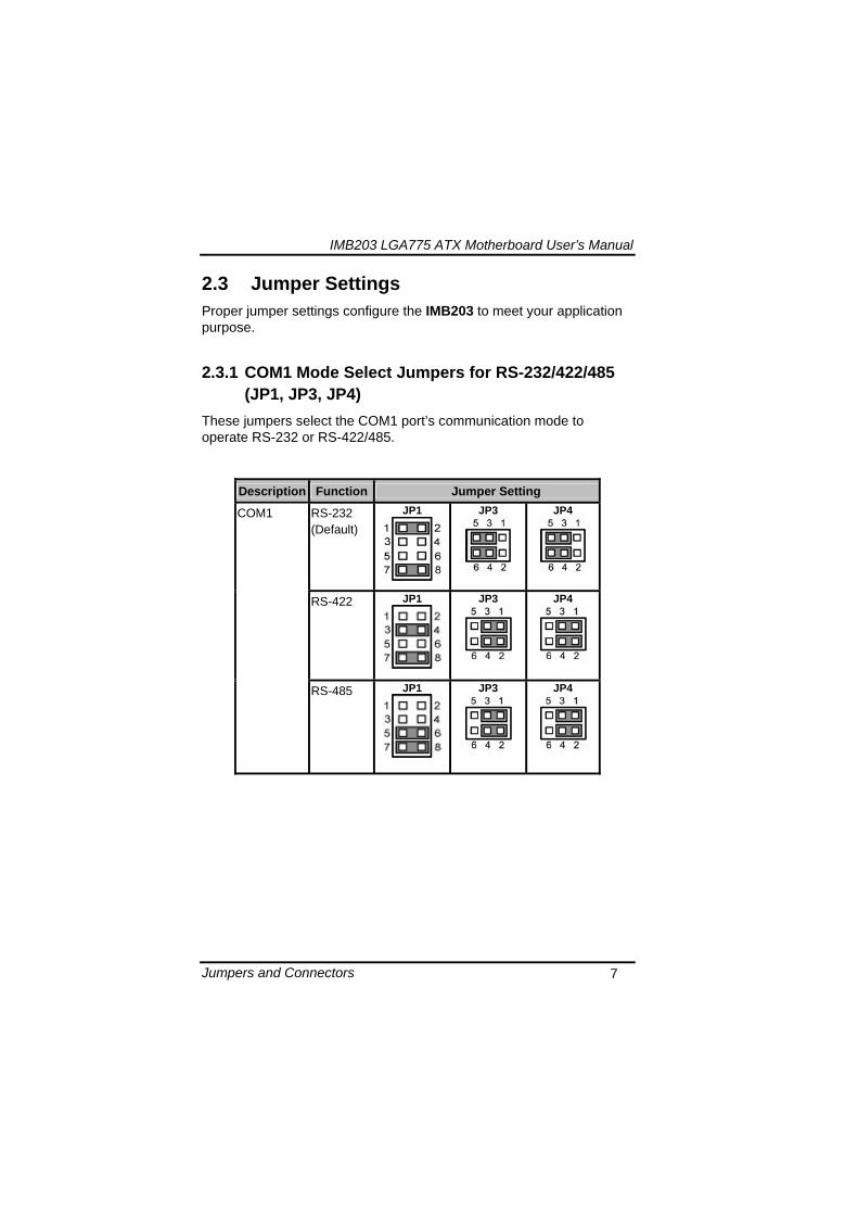
IMB203 LGA775 ATX Motherboard Userrsquos Manual
Jumpers and Connectors 7
23 Jumper Settings Proper jumper settings configure the IMB203 to meet your application purpose
231 COM1 Mode Select Jumpers for RS-232422485 (JP1 JP3 JP4)
These jumpers select the COM1 portrsquos communication mode to operate RS-232 or RS-422485
Description Function Jumper Setting
RS-232 (Default)
JP1
JP3
JP4
RS-422 JP1 JP3
JP4
COM1
RS-485 JP1 JP3
JP4
IMB203 LGA775 ATX Motherboard Userrsquos Manual
Jumpers and Connectors 8
232 Audio Amplifier Jumper (JP2)
Description Function Jumper Setting
Disable
Audio Amplifier
Enable (Default)
IMB203 LGA775 ATX Motherboard Userrsquos Manual
Jumpers and Connectors 9
233 CMOS Clear Jumper (JP7) You may need to use this jumper is to clear the CMOS memory if incorrect BIOS settings
Description Function Jumper Setting
Normal (Default)
CMOS Clear
Clear CMOS
234 TPM DisableEnable Jumper (JP9)
Description Function Jumper Setting
Enable TPM (Default)
TPM Disable Enable
Disabled
IMB203 LGA775 ATX Motherboard Userrsquos Manual
Jumpers and Connectors 10
235 ME DisableEnable Jumper (JP10)
Description Function Jumper Setting
Enable (Default)
ME Disable Enable
Disable
刪除
IMB203 LGA775 ATX Motherboard Userrsquos Manual
Jumpers and Connectors 11
24 Connectors Connectors connect this board with other parts of the system Loose or improper connection might cause problems Make sure all connectors are properly and firmly connected
Label Connector
CN1 VGA
CN2 COM 1
CN3 Audio out Mic in
CN4 Keyboard Mouse
CN5 Print Port
CN6 CN7 USB Ports
CN14 ATX 2x2
CN16 COM 2
CN17 PCI Express x1 Slot
CN18 PCI Express x4 Slot
CN19 COM 3
CN25 COM 4
CN26 DIO
CN27 CN29 CN33 CN45 USB
CN31 FAN
CN36 CN37 CN41 CN42 CN46 CN47
SATA
CN50 ATX-24Pin
CN52 F_PANEL
IMB203 LGA775 ATX Motherboard Userrsquos Manual
Jumpers and Connectors 12
IMB203 LGA775 ATX Motherboard Userrsquos Manual
Jumpers and Connectors 13
241 VGA Connector (CN1) The board supports CRT VGA with a 15-pin D-Sub connector for the CRT VGA display
Pin Signal Pin Signal Pin Signal 1 Red 2 Green 3 Blue 4 NA 5 GND 6 GND 7 GND 8 GND 9 VCC 10 GND 11 NA 12 DDC DATA
13 Horizontal Sync 14 Vertical Sync 15 DDC CLK
242 COM1 Connector (CN2) The board has the onboard serial port COM1 (CN2) a 9-pin D-Sub connector on the rear IO to support RS-232422485 with jumper selectable RS-485 with auto-flow control
Pin Signal 1 DCD Data carrier detect 2 RXD Receive data 3 TXD Transmit data 4 DTR Data terminal ready 5 GND ground 6 DSR Data set ready 7 RTS Request to send 8 CTS Clear to send 9 RI Ring indicator
IMB203 LGA775 ATX Motherboard Userrsquos Manual
Jumpers and Connectors 14
243 COM2~COM4 Connectors (CN16 CN19 CN25) The board has the onboard serial ports COM2~4 (CN16 CN19 CN25) three 25-pin 254 pitch box-header to support RS-232
Pin Signal Pin Signal
1 Data Carrier Detect (DCD) 2 Data Set Ready
(DSR)
3 Receive Data (RXD) 4 Request to Send
(RTS)
5 Transmit Data (TXD) 6 Clear to Send
(CTS)
7 Data Terminal Ready (DTR) 8 Ring Indicator (RI)
9 Ground (GND) 10 NC
244 Audio Connector (CN3)
Color Signal
Green LINE_OUT
Red MIC_IN
IMB203 LGA775 ATX Motherboard Userrsquos Manual
Jumpers and Connectors 15
245 PS2 KeyboardMouse Connector (CN4) The board supports a keyboard and Mouse interface
Pin Signal Pin Signal
1 KB Data 7 MS Data
2 NC 8 NC
3 GND 9 GND
4 VCC 10 VCC
5 KB CLK 11 MS CLK
6 NC 12 NC
246 Print Port Connector (CN5)
Print Port Connector This board has a multi-mode parallel port to support the following modes 1 Standard Mode
IBM PCXT PCAT and PS2trade are compatible with bi-directional parallel port
2 Enhanced Mode Enhanced parallel port (EPP) is compatible with EPP 17 and EPP 19 (IEEE 1284 compliant)
3 High Speed Mode Microsoft and Hewlett Packard extended capabilities port (ECP) is IEEE 1284 compliant
Please refer to next page for the list of pin assignment
IMB203 LGA775 ATX Motherboard Userrsquos Manual
Jumpers and Connectors 16
Print Port Pin Assignment (Default)
Pin Signal 1 Data Carrier Detect (DCD) 2 Data Set Ready (DSR)
3 Receive Data (RXD)
4 Request to Send (RTS) 5 Transmit Data (TXD)
6 Clear to Send (CTS)
7 Data Terminal Ready (DTR) 8 Ring Indicator (RI)
9 Ground (GND)
247 USB Port Connector (CN6 CN7) The Universal Serial Bus (USB) port connector on the board is for the installation of peripherals supporting the USB interface The CN6CN7 consists of two 4-pin standard USB ports
Pin Signal
1 5 USB Vcc
2 6 USB -
3 7 USB +
4 8 USB GND
IMB203 LGA775 ATX Motherboard Userrsquos Manual
Jumpers and Connectors 17
248 USB Connectors (CN27 CN29 CN33 CN45) The 10-pin standard Universal Serial Bus (USB) connectors CN27293345 on this board are for installing versatile USB interface peripherals
Pin Signal Pin Signal 1 USB 2 USB
3 USB2- 4 USB3-
5 USB2+ 6 USB3+
7 GND 8 GND
9 GND 10 GND
CN45
Pin Signal Pin Signal 1 USB 2 USB
3 USB4- 4 USB5-
5 USB4+ 6 USB5+
7 GND 8 GND
10 GND
CN27 CN29 CN33
249 ATX 4 Pin 12V In Connector (CN14) You can connect it to the ATX12V power supply for CPU Core Voltage
Pin Signal 1 GND 2 GND 3 +12V 4 +12V
IMB203 LGA775 ATX Motherboard Userrsquos Manual
Jumpers and Connectors 18
2410 Digital IO Port (DIO) Connector (CN26) The board is equipped an 8-channel digital IO connector CN26 that meets requirements for a system customary automation control The digital IO can be configured to control cash drawers sense warning signals from an Uninterrupted Power System (UPS) or perform store security control The digital IO is controlled via software programming
Pin Signal Pin Signal
1 DO1 2 DI1
3 DO2 4 DI2
5 DO3 6 DI3
7 DO4 8 DI4
9 GND 10 GND
2411 CPU Fan Connector (CN31) A CPU fan is always needed for cooling CPU heat The CPU fan connector provides power to the CPU fan
Pin Signal 1 Ground 2 +12V 3 Rotation Detection4 Speed Control
2412 SATA Connectors (CN36 CN37 CN41 CN42
CN46 CN47) These SATA connectors are for high-speed SATA interface ports and they can be connected to hard disk devices
Pin Signal
1 GND
2 SATA_TX+
3 SATA_TX-
CN364146
IMB203 LGA775 ATX Motherboard Userrsquos Manual
Jumpers and Connectors 19
4 GND
5 SATA_RX-
6 SATA_RX+
7 GND
IMB203 LGA775 ATX Motherboard Userrsquos Manual
Jumpers and Connectors 20
2413 ATX Power Connector (CN50) Steady and sufficient power can be supplied to all components on the board by connecting the power connector Please make sure all components and devices are properly installed before connecting the power connector If you use a 24-pin ATX power supply please remove the small cover from the power connector before plugging in the power cord otherwise please do not remove it Pin Signal Pin Signal 1 33V 2 33V
3 GND 4 5V
5 GND 6 5V
7 GND 8 PWR
9 5VSB 10 12V
11 12V 12 33V
13 33V 14 -12V
15 GND 16 PS_ON
17 GND 18 GND
19 GND 20 -5V
21 5V 22 5V
23 5V 24 GND
IMB203 LGA775 ATX Motherboard Userrsquos Manual
Jumpers and Connectors 21
2414 Front Panel Connector (CN52)
Power LED
This 3-pin connector denoted as Pin 1 and Pin 5 connects the system power LED indicator to such a switch on the case Pin 1 is assigned as + and Pin 5 as - The Power LED lights up when the system is powered ON Pin 3 is defined as GND
External Speaker and Internal Buzzer Connector
Pin 2 4 6 and 8 can be connected to the case-mounted speaker unit or internal buzzer While connecting the CPU card to an internal buzzer please short pins 2-4 while connecting to an external speaker you need to set pins 2-4 to Open and connect the speaker cable to pin 8 (+) and pin 2 (-)
ATX Power OnOff Button
This 2-pin connector denoted as Pin 9 and 10 connects the front panelrsquos ATX power button to the CPU card which allows users to control ATX power supply to be power onoff
System Reset Switch
Pin 11 and 12 can be connected to the case-mounted reset switch that reboots your computer instead of turning OFF the power switch It is a better way to reboot your system for a longer life of the systemrsquos power supply
HDD Activity LED
This connection is linked to hard drive activity LED on the control panel LED flashes when HDD is being accessed Pin 13 and 14 connect the hard disk drive to the front panel HDD LED Pin 13 assigned as - and Pin 14 as +
IMB203 LGA775 ATX Motherboard Userrsquos Manual
Jumpers and Connectors 22
MEMO
IMB203 LGA775 ATX Motherboard Userrsquos Manual
Hardware Installation 23
CHAPTER 3 HARDWARE INSTALLATION
Before installing the processor please access Intelreg website for more detailed information httpwwwintelcom
31 Installing the Processor The LGA775 processor socket comes with a cover to protect the processor Please install the processor into the CPU socket step by step as below
Hold the hook (A) of the lever and push it down Pull the lever (B) aside to unlock the cover
IMB203 LGA775 ATX Motherboard Userrsquos Manual
Hardware Installation 24
Remove the plastic cap (E) from the cover
Open the cover (C) you can see the contact
Be careful not to touch the contact (D)
IMB203 LGA775 ATX Motherboard Userrsquos Manual
Hardware Installation 25
Place the CPU down into the socket Be careful not to touch the contact
Hold the edges of the CPU and orientate it as the marked direction (G) down into the socket to match the (H) and (F) locations
IMB203 LGA775 ATX Motherboard Userrsquos Manual
Hardware Installation 26
Slightly push down the cover and hook the lever (I~J) The CPU is completely locked
Orientate the CPU cooling fan to fixing holes on the board
IMB203 LGA775 ATX Motherboard Userrsquos Manual
Hardware Installation 27
Screw the CPU cooling fan onto the board
Make sure the CPU fan is plugged to the CPU fan connector
IMB203 LGA775 ATX Motherboard Userrsquos Manual
Hardware Installation 28
32 Installing the Memory The board supports four 240-pin DDR3 DIMM memory sockets with maximum memory capacity up to 16GB Please follow steps below to install the memory modules 1 Push down latches on each side of the DIMM socket 2 Align the memory module with the socket that notches of
memory module must match the socket keys for a correct installation
3 Install the memory module into the socket and push it firmly down until it is fully seated The socket latches are levered upwards and clipped on to the edges of the DIMM
4 Install any remaining DIMM modules
IMB203 LGA775 ATX Motherboard Userrsquos Manual
Hardware Description 29
CHAPTER 4 HARDWARE DESCRIPTION
41 Microprocessors The IMB203 Series supports Intelreg Coretrade 2 Quad Coretrade 2 Duo processors which make your system operated under Windowsreg XP and Linux environments The system performance depends on the microprocessor Make sure all correct settings are arranged for your installed microprocessor to prevent the CPU from damages
42 BIOS The IMB203 Series uses AMI Plug and Play BIOS with a single 32Mbit SPI Flash
43 System Memory The IMB203 Series supports four 240-pin DDR3 DIMM sockets for a maximum memory of 16GB DDR3 SDRAMs The memory module can come in sizes of 1GB 2GB and 4GB
IMB203 LGA775 ATX Motherboard Userrsquos Manual
Hardware Description 30
44 IO Port Address Map The Intelreg Coretrade 2 Extreme Intelreg Coretrade 2 Quad Coretrade 2 Duo CPUs can communicate via IO ports There are total 1KB port addresses available for assignment to other devices via IO expansion cards
Address Devices 000-01F DMA controller 1
020-02D 024-025 028-029 02C-02D Interrupt controller 1
02E-02F Forwarded to LPC(LPC Super IO ) 030-031 034-035 038-039 03C-03D
Interrupt controller 2
040-043 050-053 TimerCounter (8254) 060 Forwarded to LPC (Microcontroller) 061 NMI
062-066 Forwarded to LPC (Microcontroller) 070-077 Real time clock NMI 080-091 DMA page register
092 Processor IF(Reset Generator) 093-09F DMA page register 0A0-0BF Interrupt controller 2 0C0-0DF DMA controller 2
0F0 Processor IF 0F8-0FF Math processor 170-177 Forward to SATA (SATA Controller) 1F0-1F7 Forward to SATA (SATA Controller)
376 Forward to SATA(SATA Controller) 378-37F Parallel Port (LPT) 380-38F SDLC 2 3A0-3AF SDLC 1 3B0-3BF MDA video card
(to be continued)
IMB203 LGA775 ATX Motherboard Userrsquos Manual
Hardware Description 31
Address Devices 3C0-3CF EGA card 3D0-3DF CGA card
3F6 Forward to SATA(SATA Controller) 3F8-3FF Serial port 1 (COM1) 2F8-2FF Serial port 2 (COM2)
45 Interrupt Controller (IRQ) Map The IMB203 Series is a 100 PC compatible control board It consists of 16 interrupt request lines and four out of them can be programmable The mapping list of the 16 interrupt request lines is shown as the following table
IRQ Parity check error IRQ0 System Timer Output
IRQ1 Keyboard
IRQ2 Interrupt rerouting from IRQ8 through IRQ15
IRQ3 Serial port 2
IRQ4 Serial port 1
IRQ5 PCI Device Share
IRQ7 Parallel port
IRQ8 Real time clock
IRQ9 ACPI Controller
IRQ10 PCI Device Share
IRQ11 PCI Device Share
IRQ12 PS2 Mouse
IRQ13 Math coprocessor
IRQ14 SATA Primary (Legacy Mode)
IRQ15 SATA Secondary (Legacy Mode)
IMB203 LGA775 ATX Motherboard Userrsquos Manual
Hardware Description 32
MEMO
IMB203 LGA775 ATX Motherboard Userrsquos Manual
AMI BIOS Setup Utility 33
CHAPTER 5 AMI BIOS SETUP UTILITY
This chapter provides users with detailed description how to set up basic system configuration through the AMIBIOS8 BIOS setup utility 51 Starting To enter the setup screens follow the steps below 1 Turn on the computer and press the ltDelgt key immediately 2 After you press the ltDeletegt key the main BIOS setup menu
displays You can access the other setup screens from the main BIOS setup menu such as the Chipset and Power menus
52 Navigation Keys The BIOS setuputility uses a key-based navigation system called hot keys Most of the BIOS setup utility hot keys can be used at any time during the setup navigation process These keys include ltF1gt ltF10gt ltEntergt ltESCgt ltArrowgt keys and so on
Note Some of navigation keys differ from one screen to another
IMB203 LGA775 ATX Motherboard Userrsquos Manual
AMI BIOS Setup Utility 34
LeftRight The Left ltArrowgt keys allow you to select a setup screen
UpDown The Up and Down ltArrowgt keys allow you to select a setup screen or sub-screen
+minus PlusMinus The Plus and Minus ltArrowgt keys allow you to change the field value of a particular setup item
Tab The ltTabgt key allows you to select setup fields
F1 The ltF1gt key allows you to display the General Help screen
F10 The ltF10gt key allows you to save any changes you have made and exit Setup Press the ltF10gt key to save your changes
Esc
The ltEscgt key allows you to discard any changes you have made and exit the Setup Press the ltEscgt key to exit the setup without saving your changes
Enter
The ltEntergt key allows you to display or change the setup option listed for a particular setup item The ltEntergt key can also allow you to display the setup sub- screens
IMB203 LGA775 ATX Motherboard Userrsquos Manual
AMI BIOS Setup Utility 35
53 Main Menu When you first enter the Setup Utility you will enter the Main setup screen You can always return to the Main setup screen by selecting the Main tab There are two Main Setup options They are described in this section The Main BIOS Setup screen is shown below
System TimeDate
Use this option to change the system time and date Highlight System Time or System Date using the ltArrowgt keys Enter new values through the keyboard Press the ltTabgt key or the ltArrowgt keys to move between fields The date must be entered in MMDDYY format The time is entered in HHMMSS format
IMB203 LGA775 ATX Motherboard Userrsquos Manual
AMI BIOS Setup Utility 36
54 Advanced Menu The Advanced menu allows users to set configuration of the CPU and other system devices You can select any of the items in the left frame of the screen to go to the sub menus
CPU Configuration IDE Configuration SuperIO Configuration Hardware Health Configuration ACPI Configuration AHCI Configuration Intel iAMT Configuration Intel VT-d Configuration MPS Configuration PCI Express Configuration Trusted Computing USB Configuration
For items marked with ldquo rdquo please press ltEntergt for more options
IMB203 LGA775 ATX Motherboard Userrsquos Manual
AMI BIOS Setup Utility 37
CPU Configuration This screen shows the CPU Configuration and you can change the value of the selected option
Max CPUID Value Limit
You can enable this item to let legacy operating systems boot even without support for CPUs with extended CPU ID functions
Execute-Disable Bit Capability This item helps you enable or disable the No-Execution Page Protection Technology
Core Multi-Processing This feature controls the functionality of the Core Multi-Processing to allow the processor to execute multitasking function
PECI Use this item PECI (Platform Environment Control Interface) to execute the processor temperature monitoring and management
IMB203 LGA775 ATX Motherboard Userrsquos Manual
AMI BIOS Setup Utility 38
Intel (R) C-STATE tech Use this item to enable or disable the C-State technology
IDE Configuration You can use this screen to select options for the IDE Configuration and change the value of the selected option A description of the selected item appears on the right side of the screen For items marked with ldquo rdquo please press ltEntergt for more options
SATA1 Configuration
Use this item to control the onboard SATA controller Here are the options for your selection Compatible Disabled and Enhanced
Configure SATA1 as Use this item to choose the SATA operation mode Here are the options for your selection IDE and AHCI
SATA2 Configuration Use this item to control the onboard SATA controller Here are the options for your selection Enhanced and Disabled
IMB203 LGA775 ATX Motherboard Userrsquos Manual
AMI BIOS Setup Utility 39
PrimarySecondaryThird IDE Master Select one of the hard disk drives to configure IDE devices installed in the system by pressing ltEntergt for more options
Fifth IDE Master Select one of the hard disk drives to configure IDE devices installed in the system by pressing ltEntergt for more options
IMB203 LGA775 ATX Motherboard Userrsquos Manual
AMI BIOS Setup Utility 40
SuperIO Configuration You can use this screen to select options for the SuperIO Configuration and change the value of the selected option A description of the selected item appears on the right side of the screen
Serial Port1 Address
This option specifies the base IO port address and Interrupt Request address of serial port 1 The Optimal setting is 3F8IRQ4 The Fail-Safe default setting is Disabled
Serial Port2 Address This option specifies the base IO port address and Interrupt Request address of serial port 2 The Optimal setting is 2F8IRQ3 The Fail-Safe setting is Disabled
Parallel Port Address This item allows you to determine the IO address for onboard parallel port There are several options for your selection
Parallel Port Mode
IMB203 LGA775 ATX Motherboard Userrsquos Manual
AMI BIOS Setup Utility 41
Select an operating mode for the onboard parallel (printer) port
Parallel Port IRQ Use this item to set up the IRQ for onboard parallel port
Serial Port3 Address This item specifies the base IO port address and Interrupt Request address of serial port 3 The Optimal setting is 3E8IRQ11 The Fail-Safe default setting is Disabled
Serial Port3 IRQ This item specifies the IRQ used by the serial port 3
Serial Port4 Address This item specifies the base IO port address and Interrupt Request address of serial port 4 The Optimal setting is 2E8IRQ10 The Fail-Safe default setting is Disabled
Serial Port4 IRQ This item specifies the IRQ used by the serial port 4
IMB203 LGA775 ATX Motherboard Userrsquos Manual
AMI BIOS Setup Utility 42
Hardware Health Configuration This screen shows the Hardware Health Configuration and a description of the selected item appears on the right side of the screen
HW Health Configuration
This screen displays the temperature of CPU and System Fan Speed Vcore etc
IMB203 LGA775 ATX Motherboard Userrsquos Manual
AMI BIOS Setup Utility 43
ACPI Configuration You can use this screen to select options for the ACPI Configuration and change the value of the selected option A description of the selected item appears on the right side of the screen
General ACPI Configuration
Scroll to this item and press ltEntergt to view the General ACPI Configuration sub menu which contains General ACPI (Advanced Configuration and Power Management Interface) options for your configuration
Advanced ACPI Configuration Scroll to this item and press ltEntergt to view the Advanced ACPI Configuration sub menu which contains Advanced ACPI (Advanced Configuration and Power Management Interface) options for your configuration
Chipset ACPI Configuration Scroll to this item and press ltEntergt to view the Chipset ACPI Configuration sub menu which contains Chipset ACPI (Advanced Configuration and Power Management
IMB203 LGA775 ATX Motherboard Userrsquos Manual
AMI BIOS Setup Utility 44
Interface) options for your configuration AHCI Configuration
You can use this screen to select options for the AHCI Configuration and change the value of the selected option A description of the selected item appears on the right side of the screen
AHCI BIOS Support You can enable or disable this item to control the AHCI function of the SATA controller
IMB203 LGA775 ATX Motherboard Userrsquos Manual
AMI BIOS Setup Utility 45
Intel iAMT Configuration You can use this screen to select options for the Intel iAMT Configuration and change the value of the selected option A description of the selected item appears on the right side of the screen
Intel iAMT Support
You can enable this item to support iAMT (active management technology) function to follow up the procedure for the access to AMI program screen
Unconfigure iAMTME Use this item to unconfigure the iAMTME settings
IMB203 LGA775 ATX Motherboard Userrsquos Manual
AMI BIOS Setup Utility 46
Intel VT-d Configuration You can use this screen to select options for the Intel VT-d Configuration and change the value of the selected option A description of the selected item appears on the right side of the screen
Intel VT-d Virtualization Technology for Directed IO (VT-d) extends Virtualization Technology (VT) roadmap by providing hardware assists for virtualization solution VT-d can help end users improve security and reliability of the systems and also improve performance of IO devices in virtualized environment Here are the options for your selection Disabled and Enabled
IMB203 LGA775 ATX Motherboard Userrsquos Manual
AMI BIOS Setup Utility 47
Remote Access Configuration You can use this screen to select options for the Remote Access Configuration and change the value of the selected option A description of the selected item appears on the right side of the screen
Remote Access Use this item to enable or disable the Remote Access function
IMB203 LGA775 ATX Motherboard Userrsquos Manual
AMI BIOS Setup Utility 48
PCI Express Configuration This screen shows the PCI Express Configuration and you can change its value A description of the selected item appears on the right side of the screen
Active State Power-Management
Use this item to enable or disable the function of Active State Power-Management to provide you with lower power consumption The default setting is Disabled
IMB203 LGA775 ATX Motherboard Userrsquos Manual
AMI BIOS Setup Utility 49
Trusted Computing You can use this screen to select options for the Trusted Computing and change the value of the selected option A description of the selected item appears on the right side of the screen
TCGTPM SUPPORT Use this item to control the Trusted Platform Module (TPM) function
IMB203 LGA775 ATX Motherboard Userrsquos Manual
AMI BIOS Setup Utility 50
USB Configuration You can use this screen to select options for the USB Configuration and change the value of the selected option A description of the selected item appears on the right side of the screen
USB Functions
This item allows you to enable or disable USB functions
Legacy USB Support Use this item to enable or disable support for USB device on legacy operating system The default setting is Enabled
USB 20 Controller Mode Use this item to configure the USB 20 controller The default setting is HiSpeed
BIOS EHCI Hand-Off Enabling this item provide the support for operating systems without an EHCI hand-off feature The default setting is Enabled
IMB203 LGA775 ATX Motherboard Userrsquos Manual
AMI BIOS Setup Utility 51
IMB203 LGA775 ATX Motherboard Userrsquos Manual
AMI BIOS Setup Utility 52
55 PCI PnP Menu The PCI PnP menu allows users to change the advanced settings for PCIPnP devices
Clear NVRAM
Use this item to clear the data in the NVRAM (CMOS) Here are the options for your selection No and Yes
Plug amp Play OS When the setting is No Use this item to configure all the devices in the system When the setting is Yes and if you install a Plug and Play operating system the operating system configures the Plug and Play devices not required for boot The default setting is No
IMB203 LGA775 ATX Motherboard Userrsquos Manual
AMI BIOS Setup Utility 53
PCI Latency Timer This item controls how long a PCI device can hold the PCI bus before another takes over The longer the latency the longer the PCI device can retain control of the bus before handing it over to another PCI device There are several options for your selection
Allocate IRQ to PCI VGA This item allows BIOS to choose an IRQ to assign for the PCI VGA card Here are the options for your selection No and Yes
Palette Snooping Some old graphic controllers need to ldquosnooprdquo on the VGA palette and then map it to their display as a way to provide boot information and VGA compatibility This item allows such snooping to take place Here are the options for your selection Disabled and Enabled
PCI IDE BusMaster This item is a toggle for the built-in driver that allows the onboard IDE controller to perform DMA (Direct Memory Access) transfer Here are the options for your selection Disabled and Enabled
OffBoard PCIISA IDE Card This item is for any other non-onboard PCIISA IDE controller adapter There are several options for your selection
IRQ3457910111415 These items will allow you to assign each system interrupt a type depending on the type of device using the interrupt The option ldquoAvailablerdquo means the IRQ is going to assign automatically Here are the options for your selection Available and Reserved
DMA Channel 013567 These items will allow you to assign each DMA channel a type depending on the type of device using the channel The option ldquoAvailablerdquo means the channel is going to assign automatically Here are the options for your selection Available and Reserved
IMB203 LGA775 ATX Motherboard Userrsquos Manual
AMI BIOS Setup Utility 54
56 Boot Menu The Boot menu allows users to change boot options of the system You can select any of the items in the left frame of the screen to go to the sub menus
Boot Settings Configuration Boot Device Priority Removable Drives
For items marked with ldquo rdquo please press ltEntergt for more options
IMB203 LGA775 ATX Motherboard Userrsquos Manual
AMI BIOS Setup Utility 55
Boot Settings Configuration
Quick Boot
Enabling this item lets the BIOS skip some power on self tests (POST) The default setting is Enabled
AddOn ROM Display Mode This item selects the display mode for option ROM The default setting is Force BIOS
Boot Num-Lock Use this item to select the power-on state for the NumLock The default setting is On
PS2 Mouse Support This item determines if the BIOS should reserve IRQ12 for the PS2 mouse or allow other devices to make use of this IRQ Here are the options for your selection Auto Enabled and Disabled
Wait For lsquoF1rsquo Of Error If this item is enabled the system waits for the F1 key to be pressed when error occurs The default setting is Enabled
Hit lsquoDELrsquo Message Display If this item is enabled the system displays the message
IMB203 LGA775 ATX Motherboard Userrsquos Manual
AMI BIOS Setup Utility 56
ldquoPress DEL to run Setuprdquo during POST The default setting is Enabled
Interrupt 19 Capture If this item is enabled this function makes the option ROMs to trap Interrupt 19 The default setting is Disabled
Boot Device Priority The Boot Device Priority screen specifies the boot device priority sequence from the available devices
IMB203 LGA775 ATX Motherboard Userrsquos Manual
AMI BIOS Setup Utility 57
Removable Drives Use this screen to view the removable drives in the system The BIOS will attempt to arrange the removable drive boot sequence automatically You can also change the booting sequence
IMB203 LGA775 ATX Motherboard Userrsquos Manual
AMI BIOS Setup Utility 58
57 Security Menu The Security menu allows users to change the security settings for the system
Supervisor Password
This item indicates whether a supervisor password has been set If the password has been installed Installed displays If not Not Installed displays
User Password This item indicates whether a user password has been set If the password has been installed Installed displays If not Not Installed displays
Change Supervisor Password Select this option and press ltEntergt to access the sub menu You can use the sub menu to change the supervisor password
Change User Password Select this option and press ltEntergt to access the sub menu You can use the sub menu to change the user password
IMB203 LGA775 ATX Motherboard Userrsquos Manual
AMI BIOS Setup Utility 59
58 Chipset Menu The Chipset menu allows users to change the advanced chipset settings You can select any of the items in the left frame of the screen to go to the sub menus
North Bridge Configuration South Bridge Configuration ME Subsystem Configuration
For items marked with ldquo rdquo please press ltEntergt for more options
IMB203 LGA775 ATX Motherboard Userrsquos Manual
AMI BIOS Setup Utility 60
North Bridge Configuration
Memory Remap Feature
Use this item to enable or disable the remapping of the overlapped PCI memory above the total physical memory Only 64-bit OS supports this function
DRAM Frequency This item allows you to control the Memory Clock
Configure DRAM Timing by SPD This item can enable or disable DRAM timing by SPD (Serial Presence Detect) device which is a small EEPROM chip on the memory module containing important information about the module speed size addressing mode and various parameters
Memory Hole You can reserve this area of system memory for ISA adapter ROM When this area is reserved it cannot be cached Check the user information of peripherals that need to use this area o f system memory for the memory requirements Here are the options Disabled and 15M-16M
IMB203 LGA775 ATX Motherboard Userrsquos Manual
AMI BIOS Setup Utility 61
Initiate Graphic Adapter When using multiple graphics cards this item can select which graphics controller to be the primary display device during boot
IGD Graphics Mode Select This item allows you to select the amount of system memory used by the internal graphics device
PEG Port ConfigurationPEG Port This item is a toggle to enable or disable the PCI Express port Here are the options for your selection Auto and Disabled
Video Function Configuration Press ltEntergt for the sub-menu for setting up video function
IMB203 LGA775 ATX Motherboard Userrsquos Manual
AMI BIOS Setup Utility 62
South Bridge Configuration
GbE Wake Up From S5 This item specifies whether the system will be awakened from the S5 power
HDA Controller This item allows you to enable or disable the HD audio support
Restore on AC Power Loss This item can control how the PC will behave once power is restored following a power outage or other unexpected shutdown
PCIE Port Configuration This item allows you to set or disable the PCI Express Ports
IMB203 LGA775 ATX Motherboard Userrsquos Manual
AMI BIOS Setup Utility 63
ME Subsystem Configuration
It is strongly recommended that you do not modify these options unless you are an advanced user
IMB203 LGA775 ATX Motherboard Userrsquos Manual
AMI BIOS Setup Utility 64
59 Exit Menu The Exit menu allows users to load your system configuration with optimal or failsafe default values
Save Changes and Exit
When you have completed the system configuration changes select this option to leave Setup and reboot the computer so the new system configuration parameters can take effect Select Save Changes and Exit from the Exit menu and press ltEntergt Select Ok to save changes and exit
Discard Changes and Exit Select this option to quit Setup without making any permanent changes to the system configuration Select Discard Changes and Exit from the Exit menu and press ltEntergt Select Ok to discard changes and exit
Load Optimal Defaults It automatically sets all Setup options to a complete set of default settings when you select this option The Optimal settings are designed for maximum system performance but may not work best for all computer applications In particular do not use the Optimal Setup options if your
IMB203 LGA775 ATX Motherboard Userrsquos Manual
AMI BIOS Setup Utility 65
computer is experiencing system configuration problems Select Load Optimal Defaults from the Exit menu and press ltEntergt
Load Fail-Safe Defaults It automatically sets all Setup options to a complete set of default settings when you select this option The Fail-Safe settings are designed for maximum system stability but not maximum performance Select the Fail-Safe Setup options if your computer is experiencing system configuration problems Select Load Fail-Safe Defaults from the Exit menu and press ltEntergt Select Ok to load Fail-Safe defaults
IMB203 LGA775 ATX Motherboard Userrsquos Manual
AMI BIOS Setup Utility 66
MEMO
IMB203 LGA775 ATX Motherboard Userrsquos Manual
Installation of Drivers 67
CHPATER 6 INSTALLATION OF DRIVERS
The device drivers are located on the Product Information CD-ROM that comes with the IMB203 Series package The auto-run function of drivers will guide you to install the utilities and device drivers under a Windows system You can follow the onscreen instructions to install these devices
Chipse VGA LAN Audio iAMT MEI
61 Installing Chipset Driver 1 Run the SETUPEXE program from the driver directory in
your driver CD Click ldquoNextrdquo to next step
IMB203 LGA775 ATX Motherboard Userrsquos Manual
Installation of Drivers 68
2 An Intelreg License Agreement appears to show you the important information Click ldquoYesrdquo to next step
3 Refer to the Readme file below to view the system requirements and installation information
IMB203 LGA775 ATX Motherboard Userrsquos Manual
Installation of Drivers 69
3-1 Please wait while running the following setup operations
3-2 Please wait while running the following setup operations
IMB203 LGA775 ATX Motherboard Userrsquos Manual
Installation of Drivers 70
4 Click ldquoFinishrdquo to complete the setup process
5 You will be asked to reboot your computer when the installation is completed Please click ldquoYes I want to restart my computer nowrdquo if you donrsquot need to install any other drivers Otherwise please click ldquoNo I will restart my computer laterrdquo and go on next step
IMB203 LGA775 ATX Motherboard Userrsquos Manual
Installation of Drivers 71
62 Installing VGA Driver 1 Run the SETUPEXE program from the driver directory in
your driver CD Click ldquoNextrdquo to next step
2 An Intelreg License Agreement appears to show you the
important information Click ldquoYesrdquo to next step
IMB203 LGA775 ATX Motherboard Userrsquos Manual
Installation of Drivers 72
3 The message of Readme File Information appears to show you the system requirements and installation information Please click ldquoNextrdquo
4 Please wait while running the following setup operations
When this message appears please click ldquoNextrdquo
IMB203 LGA775 ATX Motherboard Userrsquos Manual
Installation of Drivers 73
5 Click ldquoFinishrdquo to complete the setup process
6 You will be asked to reboot your computer when the installation is completed Please click ldquoYes I want to restart my computer nowrdquo if you donrsquot need to install any other drivers Otherwise please click ldquoNo I will restart my computer laterrdquo and click ldquoFinishrdquo to complete the installation
IMB203 LGA775 ATX Motherboard Userrsquos Manual
Installation of Drivers 74
63 Installing LAN Driver
11 Run the InstallShield Wizard for Network Connections from
the driver directory in your driver CD Click ldquoNextrdquo to next step
IMB203 LGA775 ATX Motherboard Userrsquos Manual
Installation of Drivers 75
12 An Intelreg License Agreement appears to show you the important information Click ldquoYesrdquo to next step
13 A Setup Options window appears that you can select the
program features you want to install
IMB203 LGA775 ATX Motherboard Userrsquos Manual
Installation of Drivers 76
2 Click ldquoInstallrdquo to start the installation
3 Please wait while running the following installation operation
IMB203 LGA775 ATX Motherboard Userrsquos Manual
Installation of Drivers 77
4 Click ldquoFinishrdquo to complete the installation
Note The Driver item [Wake on Directed Packet] default is Enabled under Windows Vista
格式化 字型 (符號) Arial
格式化 字型 (符號) Arial
格式化 字型 斜體 字型色彩 黑色 (符號) Arial 非加寬 緊縮
格式化 字型 斜體 字型色彩 黑色 (符號) Arial 非加寬 緊縮
格式化 字型 (符號) Arial 非加寬 緊縮
IMB203 LGA775 ATX Motherboard Userrsquos Manual
Installation of Drivers 78
64 Installing AUDIO Driver 1 Run the InstallShield Wizard for Realtek High Definition
Audio Driver from the driver directory in your driver CD Click ldquoNextrdquo to next step
IMB203 LGA775 ATX Motherboard Userrsquos Manual
Installation of Drivers 79
2 Click ldquoInstallrdquo to start the installation and wait while running the installation operation
3 Click ldquoFinishrdquo to complete the installation
IMB203 LGA775 ATX Motherboard Userrsquos Manual
Installation of Drivers 80
65 Installing iAMT (Active Management Technology) Driver
Note You must download and properly install the required NET version 35 provided from a separate downloading of the actual FimwareTools kit releases posted on VIP prior to loading the MEILMS Driver stack
651 LMS_SOL Setup
1 Run the setup program to install Intelreg Active Management Technology onto your computer It is strongly recommended that you exit all programs before continuing Click ldquoNextrdquo to next step
格式化 字型 (符號) Arial
格式化 字型 (符號) Arial 非加寬 緊縮
IMB203 LGA775 ATX Motherboard Userrsquos Manual
Installation of Drivers 81
2 An Intelreg license agreement appears that you need to continue the setup program by clicking ldquoYesrdquo to accept the terms
IMB203 LGA775 ATX Motherboard Userrsquos Manual
Installation of Drivers 82
3 Refer to the Readme file below to view the system requirements and installation information Click ldquoNextrdquo to next setup
4 Please wait while running the following installation operation
IMB203 LGA775 ATX Motherboard Userrsquos Manual
Installation of Drivers 83
5 Click ldquoFinishrdquo to complete the installation
IMB203 LGA775 ATX Motherboard Userrsquos Manual
Installation of Drivers 84
652 LMS_SOL_IS Setup
1 Run the setup program to install Intelreg Active Management Technology onto your computer It is strongly recommended that you exit all programs before continuing Click ldquoNextrdquo to next step
IMB203 LGA775 ATX Motherboard Userrsquos Manual
Installation of Drivers 85
2 An Intelreg license agreement appears that you need to continue the setup program by clicking ldquoYesrdquo to accept the terms
IMB203 LGA775 ATX Motherboard Userrsquos Manual
Installation of Drivers 86
3 Refer to the Readme file below to view the system requirements and installation information Click ldquoNextrdquo to next setup
4 Please wait while running the following installation operation
IMB203 LGA775 ATX Motherboard Userrsquos Manual
Installation of Drivers 87
5 Click ldquoFinishrdquo to complete the installation
IMB203 LGA775 ATX Motherboard Userrsquos Manual
Installation of Drivers 88
66 Installing MEI (Management Engine Interface) Driver
Note You must download and properly install the required NET version 35 provided from a separate downloading of the actual FimwareTools kit releases posted on VIP prior to loading the MEILMS Driver stack
1 Run the setup program to install Intelreg Management Engine
Interface onto your computer It is strongly recommended that you exit all programs before continuing Click ldquoNextrdquo to next step
格式化 字型 (符號) Arial
格式化 字型 (符號) Arial 非加寬 緊縮
IMB203 LGA775 ATX Motherboard Userrsquos Manual
Installation of Drivers 89
2 An Intelreg license agreement appears that you need to continue the setup program by clicking ldquoYesrdquo to accept the terms
IMB203 LGA775 ATX Motherboard Userrsquos Manual
Installation of Drivers 90
3 Refer to the Readme file below to view the system requirements and installation information Click ldquoNextrdquo to next setup
4 Please wait while running the following installation operation
IMB203 LGA775 ATX Motherboard Userrsquos Manual
Installation of Drivers 91
5 Click ldquoFinishrdquo to complete the installation
IMB203 LGA775 ATX Motherboard Userrsquos Manual
Installation of Drivers 92
MEMO
IMB203 LGA775 ATX Motherboard Userrsquos Manual
Watchdog Timer 93
APPENDIX A WATCHDOG TIMER
Watchdog Timer Setting After the system stops working for a while it can be auto-reset by the Watchdog Timer The integrated Watchdog Timer can be set up in the system reset mode by program
Using the Watchdog Function Start darr Un-Lock WDT O 2E 87 Un-lock super IO
O 2E 87 Un-lock super IO darr Set WDT Function O 2E 2D O 2F 20 Select Logic device O 2E 07 O 2F 08 darr Activate WDT O 2E 30
O 2F 01 Set Second or Minute O 2E F5
O 2F N N=00 or 08(See below table) darr Set base timer O 2E F6
O 2F M=000102hellipFF(Hex) Value=0 to 255 darr WDT counting
re-set timer O 2E F6
O 2F M M=000102hellipFF(See below table) darr
格式化
格式化 項目符號及編號
格式化 項目符號及編號
格式化 字型 8 點 字型色彩黑色
格式化 字型 8 點 字型色彩黑色
格式化 定位點 1257 字元左 + 不在 1012 字元 + 1386字元
格式化 字型 8 點 字型色彩黑色
格式化 定位點 1257 字元左 + 不在 134 字元 + 1362字元
格式化 字型色彩 黑色
格式化 字型色彩 黑色
刪除
IMB203 LGA775 ATX Motherboard Userrsquos Manual
Watchdog Timer 94
IF No re-set timer WDT time-out generate RESET IF to disable WDT O 2E 30
O 2F 00 Can be disable at any time
N=00
M= 00h Time-out Disable 01h Time-out occurs after 1 second 02h Time-out occurs after 2 second 03h Time-out occurs after 3 second helliphelliphelliphelliphelliphelliphelliphelliphellip FFh Time-out occurs after 255 second
N=08
M= 00h Time-out Disable 01h Time-out occurs after 1 minute 02h Time-out occurs after 2 minutes 03h Time-out occurs after 3 minutes helliphelliphelliphelliphelliphelliphelliphelliphellip
FFh Time-out occurs after 255 minutes
格式化 字型色彩 黑色
格式化 字型色彩 黑色
IMB203 LGA775 ATX Motherboard Userrsquos Manual
PCI IRQ Routing 95
APPENDIX B PCI IRQ ROUTING
PICMG PCI IRQ Routing
Device ID Slot Int
PCI Slot 0 31 0 BCDA PCI Slot 1 30 1 CDAB PCI Slot 2 29 2 DABC PCI Slot 3 28 3 ABCD
IMB203 LGA775 ATX Motherboard Userrsquos Manual
PCI IRQ Routing 96
MEMO
IMB203 LGA775 ATX Motherboard Userrsquos Manual
Configuring SATA for RAID Function 97
APPENDIX C CONFIGURING SATA FOR RAID
FUNCTION
Configuring SATA Hard Drive(s) for RAID Function (Controller IntelregICH10DODO DH only) Please follow up the steps below to configure SATA hard drive(s) (1) Install SATA hard drive(s) in your system (2) Enter the BIOS Setup to configure SATA controller mode and boot
sequence (3) Configure RAID by the RAID BIOS (4) Install the SATA controller driver during the OS installation Before you begin the SATA configuration please prepare (a) Two SATA hard drives (to ensure optimal performance it is
recommended that you use two hard drives with identical model and capacity) If you do not want to create RAID with the SATA controller you may prepare only one hard drive
(b) An empty formatted floppy disk (c) Windows XP setup disk (1) Installing SATA hard drive(s) in your system
Connect one end of the SATA signal cable to the rear of the SATA hard drive and the other end to available SATA port(s) on the board Then connect the power connector of power supply to the hard drive
(2) Configuring SATA controller mode and boot sequence by the BIOS Setup You have to make sure whether the SATA controller is configured correctly by system BIOS Setup and set up BIOS boot sequence for the SATA hard drive(s)
IMB203 LGA775 ATX Motherboard Userrsquos Manual
Configuring SATA for RAID Function 98
(2)-1-1 Turn on your system and then press the Del button to enter BIOS Setup during running POST (Power-On Self Test) If you want to create RAID just go to the Advanced Settings menuIDE configuration select the Configure SATA1 as and press ltEntergt for more options
IMB203 LGA775 ATX Motherboard Userrsquos Manual
Configuring SATA for RAID Function 99
(2)-1-2 A list of options appears please select RAID
IMB203 LGA775 ATX Motherboard Userrsquos Manual
Configuring SATA for RAID Function 100
(2)-2 Set CDROM for First Boot Device under the Boot Settings menu to boot CD-ROM after system restarts
(2)-3 Save and exit the BIOS Setup
IMB203 LGA775 ATX Motherboard Userrsquos Manual
Configuring SATA for RAID Function 101
(3) Configuring RAID by the RAID BIOS Enter the RAID BIOS setup utility to configure a RAID array Skip this step and proceed to Section 4 if you do not want to create a RAID (3)-1 After the POST memory testing and before the operating
system booting a message Press ltCtrl-Igt to enter Configuration Utility shows up accordingly press ltCTRL+ Igt to enter the RAID BIOS setup utility
(3)-2 After you press ltCTRL+ Igt the Create RAID Volume screen will appear If you want to create a RAID array select the Create RAID Volume option in the Main Menu and press ENTER
IMB203 LGA775 ATX Motherboard Userrsquos Manual
Configuring SATA for RAID Function 102
(3)-3-1 After entering the CREATE VOLUME MENU screen you can type the disk array name with 1~16 letters (letters cannot be special characters) in the item ldquoNamerdquo
(3)-3-2 When finished press ENTER to select a RAID level There are three RAID levels RAID0 RAID1 and RAID5 amp RAID10 Select a RAID level and press ENTER
IMB203 LGA775 ATX Motherboard Userrsquos Manual
Configuring SATA for RAID Function 103
(3)-4 Set the stripe block size The KB is the standard unit of stripe block size The stripe block size can be 4KB to 128KB After the setting press ENTER for the array capacity
(3)-5 After setting all the items on the menu select Create Volume
and press ENTER to start creating the RAID array
IMB203 LGA775 ATX Motherboard Userrsquos Manual
Configuring SATA for RAID Function 104
(3)-6 When prompting the confirmation press ldquoYldquo to create this volume or ldquoNldquo to cancel the creation
After the creation is completed you can see detailed information about the RAID Array in the DISKVOLUME INFORMATION section including RAID mode disk block size disk name and disk capacity etc
IMB203 LGA775 ATX Motherboard Userrsquos Manual
Configuring SATA for RAID Function 105
Delete RAID Volume If you want to delete a RAID volume select the Delete RAID Volume option in Main Menu Press ENTER and follow on-screen instructions
Please press [ESC] to exit the RAID BIOS utility Now you can proceed to install a SATA driver controller and the operating system
IMB203 LGA775 ATX Motherboard Userrsquos Manual
Configuring SATA for RAID Function 106
(4) Making a SATA Driver Disk To install the operating system onto a serial ATA hard disk successfully you need to install the SATA controller driver during the OS installation Without the driver the hard disk may not be recognized during the Windows setup process First of all please format a blank floppy disk Secondly follow up these steps below to produce a SATA driver disk Users can insert the Driver CD and the formatted blank floppy disk in another system And then please copy all of file of the f6flpy32 folder in the Driver CD to a floppy disk Note Please copy all of file of the f6flpy64 folder if installing 64-bit
Windows Operating System
IMB203 LGA775 ATX Motherboard Userrsquos Manual
Configuring SATA for RAID Function 107
(5) Installing the SATA controller driver during the OS installation Now the SATA driver disk is ready and BIOS settings configured you can proceed to install Windows 2000XP onto your SATA hard drive using the SATA driver Here is an example for Windows XP installation (5)-1 Restart your system to boot the Windows 2000XP Setup disk
and press F6 button as soon as you see the message Press F6 if you need to install a 3rd party SCSI or RAID driver After pressing the F6 button there will be a few moments for some files being loaded before next screen appears
IMB203 LGA775 ATX Motherboard Userrsquos Manual
Configuring SATA for RAID Function 108
(5)-2 When you see the screen below insert the floppy disk containing the SATA driver and press ldquoSrdquo
(5)-3 If the Setup correctly recognizes the driver of the floppy disk
a controller menu will appear below Use the ARROW keys to select Intel(R) ICH8RICH9RICH10RDO SATA RAID Controller and press ENTER Then it will begin to load the SATA driver from the floppy disk
IMB203 LGA775 ATX Motherboard Userrsquos Manual
Configuring SATA for RAID Function 109
Note If a message on the screen saying that one or some file(s) cannot be found please check the floppy disk or copy the correct SATA driver again from the driver CD
IMB203 LGA775 ATX Motherboard Userrsquos Manual
Configuring SATA for RAID Function 110
MEMO
IMB203 LGA775 ATX Motherboard Userrsquos Manual
iAMT Settings 111
APPENDIX D iAMT SETTINGS
The Intelreg Active Management Technology (Intelreg iAMT) has decreased a major barrier to IT efficiency that uses built-in platform capabilities and popular third-party management and security applications to allow IT a better discovering healing and protection their networked computing assets In order to utilize Intel iAMT you must enter the ME BIOS (CTRL + P during system startup) change the ME BIOS password and then select ldquoIntelreg iAMTrdquo as the manageability feature
D1 Entering MEBx 1 You must go to BIOS TO start iAMT function 2 Exit from BIOS after starting iAMT and press Ctrl+P to enter MEBx Setting
It is better to press Ctrl+P before the screen popping out
格式化
IMB203 LGA775 ATX Motherboard Userrsquos Manual
iAMT Settings 112
D2 Set amp Change Password 1 You will be asked to set a password when first log in The default
password is lsquoadminrsquo
2 You will be asked to change the password before setting ME
Change Password
IMB203 LGA775 ATX Motherboard Userrsquos Manual
iAMT Settings 113
3 You must confirm your new password while revising (as Remark 1)
Remark 1 The new password must contain (example 11qqQQ) (default value)
Eight characters
One upper case
One lower case
One number
One special symbol such as $ or
( excepted)
Underline ( _ ) and space are valid characters for password but they wonrsquot make higher complexity
IMB203 LGA775 ATX Motherboard Userrsquos Manual
iAMT Settings 114
D3 Intelreg iAMT Settings 1 Select Intelreg iAMT Configuration and press ltENTERgt
2 Key in the Host Name If Intelreg iAMT set to lsquoDHCPlsquo the Host name must be identical to the operating system mechanic
IMB203 LGA775 ATX Motherboard Userrsquos Manual
iAMT Settings 115
3 Select TCPIP to get into Network interface and set it to lsquoENABLEDrsquo into DHCP Mode and set it to lsquoDISABLEDrsquo (as Remark 2) into Domain name and set the Intel Management Engine domain name such as lsquoAMTintelcomrsquo
(3-1)
(3-2)
IMB203 LGA775 ATX Motherboard Userrsquos Manual
iAMT Settings 116
Remark 2 DHCP Mode lsquoDISABLEDlsquo if DHCP Mode is disabled you can make the following settings
IP address
Subnet mask
IMB203 LGA775 ATX Motherboard Userrsquos Manual
iAMT Settings 117
Default Gateway address
Preferred DNS address
IMB203 LGA775 ATX Motherboard Userrsquos Manual
iAMT Settings 118
Alternate DNS address
Domain name
4 Exit from MEBx after completing the iAMT settings
IMB203 LGA775 ATX Motherboard Userrsquos Manual
iAMT Settings 119
D4 iAMT Web Console 1 From a web browser please type http(IP ADDRESS)16992
which connects to iAMT Web Example http1014021416992
2 To log on you will be required to type in username and password
for access to the Web
USER admin (default value)
PASS (MEBx password)
IMB203 LGA775 ATX Motherboard Userrsquos Manual
iAMT Settings 120
3 Enter the iAMT Web
4 Click Remote Control and select commands on the right side
IMB203 LGA775 ATX Motherboard Userrsquos Manual
iAMT Settings 121
5 When you have finished using the iAMT Web console close the Web browser
IMB203 LGA775 ATX Motherboard Userrsquos Manual
iAMT Settings 122
MEMO
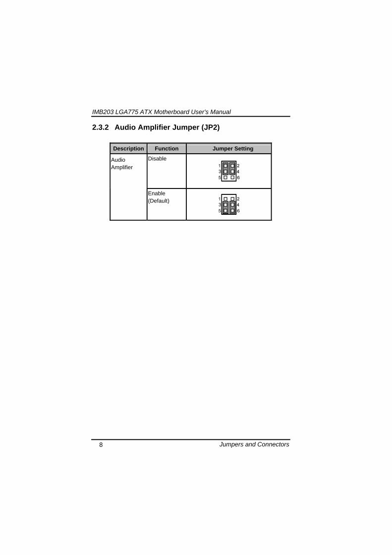
IMB203 LGA775 ATX Motherboard Userrsquos Manual
Jumpers and Connectors 9
233 CMOS Clear Jumper (JP7) You may need to use this jumper is to clear the CMOS memory if incorrect BIOS settings
Description Function Jumper Setting
Normal (Default)
CMOS Clear
Clear CMOS
234 TPM DisableEnable Jumper (JP9)
Description Function Jumper Setting
Enable TPM (Default)
TPM Disable Enable
Disabled
IMB203 LGA775 ATX Motherboard Userrsquos Manual
Jumpers and Connectors 10
235 ME DisableEnable Jumper (JP10)
Description Function Jumper Setting
Enable (Default)
ME Disable Enable
Disable
刪除
IMB203 LGA775 ATX Motherboard Userrsquos Manual
Jumpers and Connectors 11
24 Connectors Connectors connect this board with other parts of the system Loose or improper connection might cause problems Make sure all connectors are properly and firmly connected
Label Connector
CN1 VGA
CN2 COM 1
CN3 Audio out Mic in
CN4 Keyboard Mouse
CN5 Print Port
CN6 CN7 USB Ports
CN14 ATX 2x2
CN16 COM 2
CN17 PCI Express x1 Slot
CN18 PCI Express x4 Slot
CN19 COM 3
CN25 COM 4
CN26 DIO
CN27 CN29 CN33 CN45 USB
CN31 FAN
CN36 CN37 CN41 CN42 CN46 CN47
SATA
CN50 ATX-24Pin
CN52 F_PANEL
IMB203 LGA775 ATX Motherboard Userrsquos Manual
Jumpers and Connectors 12
IMB203 LGA775 ATX Motherboard Userrsquos Manual
Jumpers and Connectors 13
241 VGA Connector (CN1) The board supports CRT VGA with a 15-pin D-Sub connector for the CRT VGA display
Pin Signal Pin Signal Pin Signal 1 Red 2 Green 3 Blue 4 NA 5 GND 6 GND 7 GND 8 GND 9 VCC 10 GND 11 NA 12 DDC DATA
13 Horizontal Sync 14 Vertical Sync 15 DDC CLK
242 COM1 Connector (CN2) The board has the onboard serial port COM1 (CN2) a 9-pin D-Sub connector on the rear IO to support RS-232422485 with jumper selectable RS-485 with auto-flow control
Pin Signal 1 DCD Data carrier detect 2 RXD Receive data 3 TXD Transmit data 4 DTR Data terminal ready 5 GND ground 6 DSR Data set ready 7 RTS Request to send 8 CTS Clear to send 9 RI Ring indicator
IMB203 LGA775 ATX Motherboard Userrsquos Manual
Jumpers and Connectors 14
243 COM2~COM4 Connectors (CN16 CN19 CN25) The board has the onboard serial ports COM2~4 (CN16 CN19 CN25) three 25-pin 254 pitch box-header to support RS-232
Pin Signal Pin Signal
1 Data Carrier Detect (DCD) 2 Data Set Ready
(DSR)
3 Receive Data (RXD) 4 Request to Send
(RTS)
5 Transmit Data (TXD) 6 Clear to Send
(CTS)
7 Data Terminal Ready (DTR) 8 Ring Indicator (RI)
9 Ground (GND) 10 NC
244 Audio Connector (CN3)
Color Signal
Green LINE_OUT
Red MIC_IN
IMB203 LGA775 ATX Motherboard Userrsquos Manual
Jumpers and Connectors 15
245 PS2 KeyboardMouse Connector (CN4) The board supports a keyboard and Mouse interface
Pin Signal Pin Signal
1 KB Data 7 MS Data
2 NC 8 NC
3 GND 9 GND
4 VCC 10 VCC
5 KB CLK 11 MS CLK
6 NC 12 NC
246 Print Port Connector (CN5)
Print Port Connector This board has a multi-mode parallel port to support the following modes 1 Standard Mode
IBM PCXT PCAT and PS2trade are compatible with bi-directional parallel port
2 Enhanced Mode Enhanced parallel port (EPP) is compatible with EPP 17 and EPP 19 (IEEE 1284 compliant)
3 High Speed Mode Microsoft and Hewlett Packard extended capabilities port (ECP) is IEEE 1284 compliant
Please refer to next page for the list of pin assignment
IMB203 LGA775 ATX Motherboard Userrsquos Manual
Jumpers and Connectors 16
Print Port Pin Assignment (Default)
Pin Signal 1 Data Carrier Detect (DCD) 2 Data Set Ready (DSR)
3 Receive Data (RXD)
4 Request to Send (RTS) 5 Transmit Data (TXD)
6 Clear to Send (CTS)
7 Data Terminal Ready (DTR) 8 Ring Indicator (RI)
9 Ground (GND)
247 USB Port Connector (CN6 CN7) The Universal Serial Bus (USB) port connector on the board is for the installation of peripherals supporting the USB interface The CN6CN7 consists of two 4-pin standard USB ports
Pin Signal
1 5 USB Vcc
2 6 USB -
3 7 USB +
4 8 USB GND
IMB203 LGA775 ATX Motherboard Userrsquos Manual
Jumpers and Connectors 17
248 USB Connectors (CN27 CN29 CN33 CN45) The 10-pin standard Universal Serial Bus (USB) connectors CN27293345 on this board are for installing versatile USB interface peripherals
Pin Signal Pin Signal 1 USB 2 USB
3 USB2- 4 USB3-
5 USB2+ 6 USB3+
7 GND 8 GND
9 GND 10 GND
CN45
Pin Signal Pin Signal 1 USB 2 USB
3 USB4- 4 USB5-
5 USB4+ 6 USB5+
7 GND 8 GND
10 GND
CN27 CN29 CN33
249 ATX 4 Pin 12V In Connector (CN14) You can connect it to the ATX12V power supply for CPU Core Voltage
Pin Signal 1 GND 2 GND 3 +12V 4 +12V
IMB203 LGA775 ATX Motherboard Userrsquos Manual
Jumpers and Connectors 18
2410 Digital IO Port (DIO) Connector (CN26) The board is equipped an 8-channel digital IO connector CN26 that meets requirements for a system customary automation control The digital IO can be configured to control cash drawers sense warning signals from an Uninterrupted Power System (UPS) or perform store security control The digital IO is controlled via software programming
Pin Signal Pin Signal
1 DO1 2 DI1
3 DO2 4 DI2
5 DO3 6 DI3
7 DO4 8 DI4
9 GND 10 GND
2411 CPU Fan Connector (CN31) A CPU fan is always needed for cooling CPU heat The CPU fan connector provides power to the CPU fan
Pin Signal 1 Ground 2 +12V 3 Rotation Detection4 Speed Control
2412 SATA Connectors (CN36 CN37 CN41 CN42
CN46 CN47) These SATA connectors are for high-speed SATA interface ports and they can be connected to hard disk devices
Pin Signal
1 GND
2 SATA_TX+
3 SATA_TX-
CN364146
IMB203 LGA775 ATX Motherboard Userrsquos Manual
Jumpers and Connectors 19
4 GND
5 SATA_RX-
6 SATA_RX+
7 GND
IMB203 LGA775 ATX Motherboard Userrsquos Manual
Jumpers and Connectors 20
2413 ATX Power Connector (CN50) Steady and sufficient power can be supplied to all components on the board by connecting the power connector Please make sure all components and devices are properly installed before connecting the power connector If you use a 24-pin ATX power supply please remove the small cover from the power connector before plugging in the power cord otherwise please do not remove it Pin Signal Pin Signal 1 33V 2 33V
3 GND 4 5V
5 GND 6 5V
7 GND 8 PWR
9 5VSB 10 12V
11 12V 12 33V
13 33V 14 -12V
15 GND 16 PS_ON
17 GND 18 GND
19 GND 20 -5V
21 5V 22 5V
23 5V 24 GND
IMB203 LGA775 ATX Motherboard Userrsquos Manual
Jumpers and Connectors 21
2414 Front Panel Connector (CN52)
Power LED
This 3-pin connector denoted as Pin 1 and Pin 5 connects the system power LED indicator to such a switch on the case Pin 1 is assigned as + and Pin 5 as - The Power LED lights up when the system is powered ON Pin 3 is defined as GND
External Speaker and Internal Buzzer Connector
Pin 2 4 6 and 8 can be connected to the case-mounted speaker unit or internal buzzer While connecting the CPU card to an internal buzzer please short pins 2-4 while connecting to an external speaker you need to set pins 2-4 to Open and connect the speaker cable to pin 8 (+) and pin 2 (-)
ATX Power OnOff Button
This 2-pin connector denoted as Pin 9 and 10 connects the front panelrsquos ATX power button to the CPU card which allows users to control ATX power supply to be power onoff
System Reset Switch
Pin 11 and 12 can be connected to the case-mounted reset switch that reboots your computer instead of turning OFF the power switch It is a better way to reboot your system for a longer life of the systemrsquos power supply
HDD Activity LED
This connection is linked to hard drive activity LED on the control panel LED flashes when HDD is being accessed Pin 13 and 14 connect the hard disk drive to the front panel HDD LED Pin 13 assigned as - and Pin 14 as +
IMB203 LGA775 ATX Motherboard Userrsquos Manual
Jumpers and Connectors 22
MEMO
IMB203 LGA775 ATX Motherboard Userrsquos Manual
Hardware Installation 23
CHAPTER 3 HARDWARE INSTALLATION
Before installing the processor please access Intelreg website for more detailed information httpwwwintelcom
31 Installing the Processor The LGA775 processor socket comes with a cover to protect the processor Please install the processor into the CPU socket step by step as below
Hold the hook (A) of the lever and push it down Pull the lever (B) aside to unlock the cover
IMB203 LGA775 ATX Motherboard Userrsquos Manual
Hardware Installation 24
Remove the plastic cap (E) from the cover
Open the cover (C) you can see the contact
Be careful not to touch the contact (D)
IMB203 LGA775 ATX Motherboard Userrsquos Manual
Hardware Installation 25
Place the CPU down into the socket Be careful not to touch the contact
Hold the edges of the CPU and orientate it as the marked direction (G) down into the socket to match the (H) and (F) locations
IMB203 LGA775 ATX Motherboard Userrsquos Manual
Hardware Installation 26
Slightly push down the cover and hook the lever (I~J) The CPU is completely locked
Orientate the CPU cooling fan to fixing holes on the board
IMB203 LGA775 ATX Motherboard Userrsquos Manual
Hardware Installation 27
Screw the CPU cooling fan onto the board
Make sure the CPU fan is plugged to the CPU fan connector
IMB203 LGA775 ATX Motherboard Userrsquos Manual
Hardware Installation 28
32 Installing the Memory The board supports four 240-pin DDR3 DIMM memory sockets with maximum memory capacity up to 16GB Please follow steps below to install the memory modules 1 Push down latches on each side of the DIMM socket 2 Align the memory module with the socket that notches of
memory module must match the socket keys for a correct installation
3 Install the memory module into the socket and push it firmly down until it is fully seated The socket latches are levered upwards and clipped on to the edges of the DIMM
4 Install any remaining DIMM modules
IMB203 LGA775 ATX Motherboard Userrsquos Manual
Hardware Description 29
CHAPTER 4 HARDWARE DESCRIPTION
41 Microprocessors The IMB203 Series supports Intelreg Coretrade 2 Quad Coretrade 2 Duo processors which make your system operated under Windowsreg XP and Linux environments The system performance depends on the microprocessor Make sure all correct settings are arranged for your installed microprocessor to prevent the CPU from damages
42 BIOS The IMB203 Series uses AMI Plug and Play BIOS with a single 32Mbit SPI Flash
43 System Memory The IMB203 Series supports four 240-pin DDR3 DIMM sockets for a maximum memory of 16GB DDR3 SDRAMs The memory module can come in sizes of 1GB 2GB and 4GB
IMB203 LGA775 ATX Motherboard Userrsquos Manual
Hardware Description 30
44 IO Port Address Map The Intelreg Coretrade 2 Extreme Intelreg Coretrade 2 Quad Coretrade 2 Duo CPUs can communicate via IO ports There are total 1KB port addresses available for assignment to other devices via IO expansion cards
Address Devices 000-01F DMA controller 1
020-02D 024-025 028-029 02C-02D Interrupt controller 1
02E-02F Forwarded to LPC(LPC Super IO ) 030-031 034-035 038-039 03C-03D
Interrupt controller 2
040-043 050-053 TimerCounter (8254) 060 Forwarded to LPC (Microcontroller) 061 NMI
062-066 Forwarded to LPC (Microcontroller) 070-077 Real time clock NMI 080-091 DMA page register
092 Processor IF(Reset Generator) 093-09F DMA page register 0A0-0BF Interrupt controller 2 0C0-0DF DMA controller 2
0F0 Processor IF 0F8-0FF Math processor 170-177 Forward to SATA (SATA Controller) 1F0-1F7 Forward to SATA (SATA Controller)
376 Forward to SATA(SATA Controller) 378-37F Parallel Port (LPT) 380-38F SDLC 2 3A0-3AF SDLC 1 3B0-3BF MDA video card
(to be continued)
IMB203 LGA775 ATX Motherboard Userrsquos Manual
Hardware Description 31
Address Devices 3C0-3CF EGA card 3D0-3DF CGA card
3F6 Forward to SATA(SATA Controller) 3F8-3FF Serial port 1 (COM1) 2F8-2FF Serial port 2 (COM2)
45 Interrupt Controller (IRQ) Map The IMB203 Series is a 100 PC compatible control board It consists of 16 interrupt request lines and four out of them can be programmable The mapping list of the 16 interrupt request lines is shown as the following table
IRQ Parity check error IRQ0 System Timer Output
IRQ1 Keyboard
IRQ2 Interrupt rerouting from IRQ8 through IRQ15
IRQ3 Serial port 2
IRQ4 Serial port 1
IRQ5 PCI Device Share
IRQ7 Parallel port
IRQ8 Real time clock
IRQ9 ACPI Controller
IRQ10 PCI Device Share
IRQ11 PCI Device Share
IRQ12 PS2 Mouse
IRQ13 Math coprocessor
IRQ14 SATA Primary (Legacy Mode)
IRQ15 SATA Secondary (Legacy Mode)
IMB203 LGA775 ATX Motherboard Userrsquos Manual
Hardware Description 32
MEMO
IMB203 LGA775 ATX Motherboard Userrsquos Manual
AMI BIOS Setup Utility 33
CHAPTER 5 AMI BIOS SETUP UTILITY
This chapter provides users with detailed description how to set up basic system configuration through the AMIBIOS8 BIOS setup utility 51 Starting To enter the setup screens follow the steps below 1 Turn on the computer and press the ltDelgt key immediately 2 After you press the ltDeletegt key the main BIOS setup menu
displays You can access the other setup screens from the main BIOS setup menu such as the Chipset and Power menus
52 Navigation Keys The BIOS setuputility uses a key-based navigation system called hot keys Most of the BIOS setup utility hot keys can be used at any time during the setup navigation process These keys include ltF1gt ltF10gt ltEntergt ltESCgt ltArrowgt keys and so on
Note Some of navigation keys differ from one screen to another
IMB203 LGA775 ATX Motherboard Userrsquos Manual
AMI BIOS Setup Utility 34
LeftRight The Left ltArrowgt keys allow you to select a setup screen
UpDown The Up and Down ltArrowgt keys allow you to select a setup screen or sub-screen
+minus PlusMinus The Plus and Minus ltArrowgt keys allow you to change the field value of a particular setup item
Tab The ltTabgt key allows you to select setup fields
F1 The ltF1gt key allows you to display the General Help screen
F10 The ltF10gt key allows you to save any changes you have made and exit Setup Press the ltF10gt key to save your changes
Esc
The ltEscgt key allows you to discard any changes you have made and exit the Setup Press the ltEscgt key to exit the setup without saving your changes
Enter
The ltEntergt key allows you to display or change the setup option listed for a particular setup item The ltEntergt key can also allow you to display the setup sub- screens
IMB203 LGA775 ATX Motherboard Userrsquos Manual
AMI BIOS Setup Utility 35
53 Main Menu When you first enter the Setup Utility you will enter the Main setup screen You can always return to the Main setup screen by selecting the Main tab There are two Main Setup options They are described in this section The Main BIOS Setup screen is shown below
System TimeDate
Use this option to change the system time and date Highlight System Time or System Date using the ltArrowgt keys Enter new values through the keyboard Press the ltTabgt key or the ltArrowgt keys to move between fields The date must be entered in MMDDYY format The time is entered in HHMMSS format
IMB203 LGA775 ATX Motherboard Userrsquos Manual
AMI BIOS Setup Utility 36
54 Advanced Menu The Advanced menu allows users to set configuration of the CPU and other system devices You can select any of the items in the left frame of the screen to go to the sub menus
CPU Configuration IDE Configuration SuperIO Configuration Hardware Health Configuration ACPI Configuration AHCI Configuration Intel iAMT Configuration Intel VT-d Configuration MPS Configuration PCI Express Configuration Trusted Computing USB Configuration
For items marked with ldquo rdquo please press ltEntergt for more options
IMB203 LGA775 ATX Motherboard Userrsquos Manual
AMI BIOS Setup Utility 37
CPU Configuration This screen shows the CPU Configuration and you can change the value of the selected option
Max CPUID Value Limit
You can enable this item to let legacy operating systems boot even without support for CPUs with extended CPU ID functions
Execute-Disable Bit Capability This item helps you enable or disable the No-Execution Page Protection Technology
Core Multi-Processing This feature controls the functionality of the Core Multi-Processing to allow the processor to execute multitasking function
PECI Use this item PECI (Platform Environment Control Interface) to execute the processor temperature monitoring and management
IMB203 LGA775 ATX Motherboard Userrsquos Manual
AMI BIOS Setup Utility 38
Intel (R) C-STATE tech Use this item to enable or disable the C-State technology
IDE Configuration You can use this screen to select options for the IDE Configuration and change the value of the selected option A description of the selected item appears on the right side of the screen For items marked with ldquo rdquo please press ltEntergt for more options
SATA1 Configuration
Use this item to control the onboard SATA controller Here are the options for your selection Compatible Disabled and Enhanced
Configure SATA1 as Use this item to choose the SATA operation mode Here are the options for your selection IDE and AHCI
SATA2 Configuration Use this item to control the onboard SATA controller Here are the options for your selection Enhanced and Disabled
IMB203 LGA775 ATX Motherboard Userrsquos Manual
AMI BIOS Setup Utility 39
PrimarySecondaryThird IDE Master Select one of the hard disk drives to configure IDE devices installed in the system by pressing ltEntergt for more options
Fifth IDE Master Select one of the hard disk drives to configure IDE devices installed in the system by pressing ltEntergt for more options
IMB203 LGA775 ATX Motherboard Userrsquos Manual
AMI BIOS Setup Utility 40
SuperIO Configuration You can use this screen to select options for the SuperIO Configuration and change the value of the selected option A description of the selected item appears on the right side of the screen
Serial Port1 Address
This option specifies the base IO port address and Interrupt Request address of serial port 1 The Optimal setting is 3F8IRQ4 The Fail-Safe default setting is Disabled
Serial Port2 Address This option specifies the base IO port address and Interrupt Request address of serial port 2 The Optimal setting is 2F8IRQ3 The Fail-Safe setting is Disabled
Parallel Port Address This item allows you to determine the IO address for onboard parallel port There are several options for your selection
Parallel Port Mode
IMB203 LGA775 ATX Motherboard Userrsquos Manual
AMI BIOS Setup Utility 41
Select an operating mode for the onboard parallel (printer) port
Parallel Port IRQ Use this item to set up the IRQ for onboard parallel port
Serial Port3 Address This item specifies the base IO port address and Interrupt Request address of serial port 3 The Optimal setting is 3E8IRQ11 The Fail-Safe default setting is Disabled
Serial Port3 IRQ This item specifies the IRQ used by the serial port 3
Serial Port4 Address This item specifies the base IO port address and Interrupt Request address of serial port 4 The Optimal setting is 2E8IRQ10 The Fail-Safe default setting is Disabled
Serial Port4 IRQ This item specifies the IRQ used by the serial port 4
IMB203 LGA775 ATX Motherboard Userrsquos Manual
AMI BIOS Setup Utility 42
Hardware Health Configuration This screen shows the Hardware Health Configuration and a description of the selected item appears on the right side of the screen
HW Health Configuration
This screen displays the temperature of CPU and System Fan Speed Vcore etc
IMB203 LGA775 ATX Motherboard Userrsquos Manual
AMI BIOS Setup Utility 43
ACPI Configuration You can use this screen to select options for the ACPI Configuration and change the value of the selected option A description of the selected item appears on the right side of the screen
General ACPI Configuration
Scroll to this item and press ltEntergt to view the General ACPI Configuration sub menu which contains General ACPI (Advanced Configuration and Power Management Interface) options for your configuration
Advanced ACPI Configuration Scroll to this item and press ltEntergt to view the Advanced ACPI Configuration sub menu which contains Advanced ACPI (Advanced Configuration and Power Management Interface) options for your configuration
Chipset ACPI Configuration Scroll to this item and press ltEntergt to view the Chipset ACPI Configuration sub menu which contains Chipset ACPI (Advanced Configuration and Power Management
IMB203 LGA775 ATX Motherboard Userrsquos Manual
AMI BIOS Setup Utility 44
Interface) options for your configuration AHCI Configuration
You can use this screen to select options for the AHCI Configuration and change the value of the selected option A description of the selected item appears on the right side of the screen
AHCI BIOS Support You can enable or disable this item to control the AHCI function of the SATA controller
IMB203 LGA775 ATX Motherboard Userrsquos Manual
AMI BIOS Setup Utility 45
Intel iAMT Configuration You can use this screen to select options for the Intel iAMT Configuration and change the value of the selected option A description of the selected item appears on the right side of the screen
Intel iAMT Support
You can enable this item to support iAMT (active management technology) function to follow up the procedure for the access to AMI program screen
Unconfigure iAMTME Use this item to unconfigure the iAMTME settings
IMB203 LGA775 ATX Motherboard Userrsquos Manual
AMI BIOS Setup Utility 46
Intel VT-d Configuration You can use this screen to select options for the Intel VT-d Configuration and change the value of the selected option A description of the selected item appears on the right side of the screen
Intel VT-d Virtualization Technology for Directed IO (VT-d) extends Virtualization Technology (VT) roadmap by providing hardware assists for virtualization solution VT-d can help end users improve security and reliability of the systems and also improve performance of IO devices in virtualized environment Here are the options for your selection Disabled and Enabled
IMB203 LGA775 ATX Motherboard Userrsquos Manual
AMI BIOS Setup Utility 47
Remote Access Configuration You can use this screen to select options for the Remote Access Configuration and change the value of the selected option A description of the selected item appears on the right side of the screen
Remote Access Use this item to enable or disable the Remote Access function
IMB203 LGA775 ATX Motherboard Userrsquos Manual
AMI BIOS Setup Utility 48
PCI Express Configuration This screen shows the PCI Express Configuration and you can change its value A description of the selected item appears on the right side of the screen
Active State Power-Management
Use this item to enable or disable the function of Active State Power-Management to provide you with lower power consumption The default setting is Disabled
IMB203 LGA775 ATX Motherboard Userrsquos Manual
AMI BIOS Setup Utility 49
Trusted Computing You can use this screen to select options for the Trusted Computing and change the value of the selected option A description of the selected item appears on the right side of the screen
TCGTPM SUPPORT Use this item to control the Trusted Platform Module (TPM) function
IMB203 LGA775 ATX Motherboard Userrsquos Manual
AMI BIOS Setup Utility 50
USB Configuration You can use this screen to select options for the USB Configuration and change the value of the selected option A description of the selected item appears on the right side of the screen
USB Functions
This item allows you to enable or disable USB functions
Legacy USB Support Use this item to enable or disable support for USB device on legacy operating system The default setting is Enabled
USB 20 Controller Mode Use this item to configure the USB 20 controller The default setting is HiSpeed
BIOS EHCI Hand-Off Enabling this item provide the support for operating systems without an EHCI hand-off feature The default setting is Enabled
IMB203 LGA775 ATX Motherboard Userrsquos Manual
AMI BIOS Setup Utility 51
IMB203 LGA775 ATX Motherboard Userrsquos Manual
AMI BIOS Setup Utility 52
55 PCI PnP Menu The PCI PnP menu allows users to change the advanced settings for PCIPnP devices
Clear NVRAM
Use this item to clear the data in the NVRAM (CMOS) Here are the options for your selection No and Yes
Plug amp Play OS When the setting is No Use this item to configure all the devices in the system When the setting is Yes and if you install a Plug and Play operating system the operating system configures the Plug and Play devices not required for boot The default setting is No
IMB203 LGA775 ATX Motherboard Userrsquos Manual
AMI BIOS Setup Utility 53
PCI Latency Timer This item controls how long a PCI device can hold the PCI bus before another takes over The longer the latency the longer the PCI device can retain control of the bus before handing it over to another PCI device There are several options for your selection
Allocate IRQ to PCI VGA This item allows BIOS to choose an IRQ to assign for the PCI VGA card Here are the options for your selection No and Yes
Palette Snooping Some old graphic controllers need to ldquosnooprdquo on the VGA palette and then map it to their display as a way to provide boot information and VGA compatibility This item allows such snooping to take place Here are the options for your selection Disabled and Enabled
PCI IDE BusMaster This item is a toggle for the built-in driver that allows the onboard IDE controller to perform DMA (Direct Memory Access) transfer Here are the options for your selection Disabled and Enabled
OffBoard PCIISA IDE Card This item is for any other non-onboard PCIISA IDE controller adapter There are several options for your selection
IRQ3457910111415 These items will allow you to assign each system interrupt a type depending on the type of device using the interrupt The option ldquoAvailablerdquo means the IRQ is going to assign automatically Here are the options for your selection Available and Reserved
DMA Channel 013567 These items will allow you to assign each DMA channel a type depending on the type of device using the channel The option ldquoAvailablerdquo means the channel is going to assign automatically Here are the options for your selection Available and Reserved
IMB203 LGA775 ATX Motherboard Userrsquos Manual
AMI BIOS Setup Utility 54
56 Boot Menu The Boot menu allows users to change boot options of the system You can select any of the items in the left frame of the screen to go to the sub menus
Boot Settings Configuration Boot Device Priority Removable Drives
For items marked with ldquo rdquo please press ltEntergt for more options
IMB203 LGA775 ATX Motherboard Userrsquos Manual
AMI BIOS Setup Utility 55
Boot Settings Configuration
Quick Boot
Enabling this item lets the BIOS skip some power on self tests (POST) The default setting is Enabled
AddOn ROM Display Mode This item selects the display mode for option ROM The default setting is Force BIOS
Boot Num-Lock Use this item to select the power-on state for the NumLock The default setting is On
PS2 Mouse Support This item determines if the BIOS should reserve IRQ12 for the PS2 mouse or allow other devices to make use of this IRQ Here are the options for your selection Auto Enabled and Disabled
Wait For lsquoF1rsquo Of Error If this item is enabled the system waits for the F1 key to be pressed when error occurs The default setting is Enabled
Hit lsquoDELrsquo Message Display If this item is enabled the system displays the message
IMB203 LGA775 ATX Motherboard Userrsquos Manual
AMI BIOS Setup Utility 56
ldquoPress DEL to run Setuprdquo during POST The default setting is Enabled
Interrupt 19 Capture If this item is enabled this function makes the option ROMs to trap Interrupt 19 The default setting is Disabled
Boot Device Priority The Boot Device Priority screen specifies the boot device priority sequence from the available devices
IMB203 LGA775 ATX Motherboard Userrsquos Manual
AMI BIOS Setup Utility 57
Removable Drives Use this screen to view the removable drives in the system The BIOS will attempt to arrange the removable drive boot sequence automatically You can also change the booting sequence
IMB203 LGA775 ATX Motherboard Userrsquos Manual
AMI BIOS Setup Utility 58
57 Security Menu The Security menu allows users to change the security settings for the system
Supervisor Password
This item indicates whether a supervisor password has been set If the password has been installed Installed displays If not Not Installed displays
User Password This item indicates whether a user password has been set If the password has been installed Installed displays If not Not Installed displays
Change Supervisor Password Select this option and press ltEntergt to access the sub menu You can use the sub menu to change the supervisor password
Change User Password Select this option and press ltEntergt to access the sub menu You can use the sub menu to change the user password
IMB203 LGA775 ATX Motherboard Userrsquos Manual
AMI BIOS Setup Utility 59
58 Chipset Menu The Chipset menu allows users to change the advanced chipset settings You can select any of the items in the left frame of the screen to go to the sub menus
North Bridge Configuration South Bridge Configuration ME Subsystem Configuration
For items marked with ldquo rdquo please press ltEntergt for more options
IMB203 LGA775 ATX Motherboard Userrsquos Manual
AMI BIOS Setup Utility 60
North Bridge Configuration
Memory Remap Feature
Use this item to enable or disable the remapping of the overlapped PCI memory above the total physical memory Only 64-bit OS supports this function
DRAM Frequency This item allows you to control the Memory Clock
Configure DRAM Timing by SPD This item can enable or disable DRAM timing by SPD (Serial Presence Detect) device which is a small EEPROM chip on the memory module containing important information about the module speed size addressing mode and various parameters
Memory Hole You can reserve this area of system memory for ISA adapter ROM When this area is reserved it cannot be cached Check the user information of peripherals that need to use this area o f system memory for the memory requirements Here are the options Disabled and 15M-16M
IMB203 LGA775 ATX Motherboard Userrsquos Manual
AMI BIOS Setup Utility 61
Initiate Graphic Adapter When using multiple graphics cards this item can select which graphics controller to be the primary display device during boot
IGD Graphics Mode Select This item allows you to select the amount of system memory used by the internal graphics device
PEG Port ConfigurationPEG Port This item is a toggle to enable or disable the PCI Express port Here are the options for your selection Auto and Disabled
Video Function Configuration Press ltEntergt for the sub-menu for setting up video function
IMB203 LGA775 ATX Motherboard Userrsquos Manual
AMI BIOS Setup Utility 62
South Bridge Configuration
GbE Wake Up From S5 This item specifies whether the system will be awakened from the S5 power
HDA Controller This item allows you to enable or disable the HD audio support
Restore on AC Power Loss This item can control how the PC will behave once power is restored following a power outage or other unexpected shutdown
PCIE Port Configuration This item allows you to set or disable the PCI Express Ports
IMB203 LGA775 ATX Motherboard Userrsquos Manual
AMI BIOS Setup Utility 63
ME Subsystem Configuration
It is strongly recommended that you do not modify these options unless you are an advanced user
IMB203 LGA775 ATX Motherboard Userrsquos Manual
AMI BIOS Setup Utility 64
59 Exit Menu The Exit menu allows users to load your system configuration with optimal or failsafe default values
Save Changes and Exit
When you have completed the system configuration changes select this option to leave Setup and reboot the computer so the new system configuration parameters can take effect Select Save Changes and Exit from the Exit menu and press ltEntergt Select Ok to save changes and exit
Discard Changes and Exit Select this option to quit Setup without making any permanent changes to the system configuration Select Discard Changes and Exit from the Exit menu and press ltEntergt Select Ok to discard changes and exit
Load Optimal Defaults It automatically sets all Setup options to a complete set of default settings when you select this option The Optimal settings are designed for maximum system performance but may not work best for all computer applications In particular do not use the Optimal Setup options if your
IMB203 LGA775 ATX Motherboard Userrsquos Manual
AMI BIOS Setup Utility 65
computer is experiencing system configuration problems Select Load Optimal Defaults from the Exit menu and press ltEntergt
Load Fail-Safe Defaults It automatically sets all Setup options to a complete set of default settings when you select this option The Fail-Safe settings are designed for maximum system stability but not maximum performance Select the Fail-Safe Setup options if your computer is experiencing system configuration problems Select Load Fail-Safe Defaults from the Exit menu and press ltEntergt Select Ok to load Fail-Safe defaults
IMB203 LGA775 ATX Motherboard Userrsquos Manual
AMI BIOS Setup Utility 66
MEMO
IMB203 LGA775 ATX Motherboard Userrsquos Manual
Installation of Drivers 67
CHPATER 6 INSTALLATION OF DRIVERS
The device drivers are located on the Product Information CD-ROM that comes with the IMB203 Series package The auto-run function of drivers will guide you to install the utilities and device drivers under a Windows system You can follow the onscreen instructions to install these devices
Chipse VGA LAN Audio iAMT MEI
61 Installing Chipset Driver 1 Run the SETUPEXE program from the driver directory in
your driver CD Click ldquoNextrdquo to next step
IMB203 LGA775 ATX Motherboard Userrsquos Manual
Installation of Drivers 68
2 An Intelreg License Agreement appears to show you the important information Click ldquoYesrdquo to next step
3 Refer to the Readme file below to view the system requirements and installation information
IMB203 LGA775 ATX Motherboard Userrsquos Manual
Installation of Drivers 69
3-1 Please wait while running the following setup operations
3-2 Please wait while running the following setup operations
IMB203 LGA775 ATX Motherboard Userrsquos Manual
Installation of Drivers 70
4 Click ldquoFinishrdquo to complete the setup process
5 You will be asked to reboot your computer when the installation is completed Please click ldquoYes I want to restart my computer nowrdquo if you donrsquot need to install any other drivers Otherwise please click ldquoNo I will restart my computer laterrdquo and go on next step
IMB203 LGA775 ATX Motherboard Userrsquos Manual
Installation of Drivers 71
62 Installing VGA Driver 1 Run the SETUPEXE program from the driver directory in
your driver CD Click ldquoNextrdquo to next step
2 An Intelreg License Agreement appears to show you the
important information Click ldquoYesrdquo to next step
IMB203 LGA775 ATX Motherboard Userrsquos Manual
Installation of Drivers 72
3 The message of Readme File Information appears to show you the system requirements and installation information Please click ldquoNextrdquo
4 Please wait while running the following setup operations
When this message appears please click ldquoNextrdquo
IMB203 LGA775 ATX Motherboard Userrsquos Manual
Installation of Drivers 73
5 Click ldquoFinishrdquo to complete the setup process
6 You will be asked to reboot your computer when the installation is completed Please click ldquoYes I want to restart my computer nowrdquo if you donrsquot need to install any other drivers Otherwise please click ldquoNo I will restart my computer laterrdquo and click ldquoFinishrdquo to complete the installation
IMB203 LGA775 ATX Motherboard Userrsquos Manual
Installation of Drivers 74
63 Installing LAN Driver
11 Run the InstallShield Wizard for Network Connections from
the driver directory in your driver CD Click ldquoNextrdquo to next step
IMB203 LGA775 ATX Motherboard Userrsquos Manual
Installation of Drivers 75
12 An Intelreg License Agreement appears to show you the important information Click ldquoYesrdquo to next step
13 A Setup Options window appears that you can select the
program features you want to install
IMB203 LGA775 ATX Motherboard Userrsquos Manual
Installation of Drivers 76
2 Click ldquoInstallrdquo to start the installation
3 Please wait while running the following installation operation
IMB203 LGA775 ATX Motherboard Userrsquos Manual
Installation of Drivers 77
4 Click ldquoFinishrdquo to complete the installation
Note The Driver item [Wake on Directed Packet] default is Enabled under Windows Vista
格式化 字型 (符號) Arial
格式化 字型 (符號) Arial
格式化 字型 斜體 字型色彩 黑色 (符號) Arial 非加寬 緊縮
格式化 字型 斜體 字型色彩 黑色 (符號) Arial 非加寬 緊縮
格式化 字型 (符號) Arial 非加寬 緊縮
IMB203 LGA775 ATX Motherboard Userrsquos Manual
Installation of Drivers 78
64 Installing AUDIO Driver 1 Run the InstallShield Wizard for Realtek High Definition
Audio Driver from the driver directory in your driver CD Click ldquoNextrdquo to next step
IMB203 LGA775 ATX Motherboard Userrsquos Manual
Installation of Drivers 79
2 Click ldquoInstallrdquo to start the installation and wait while running the installation operation
3 Click ldquoFinishrdquo to complete the installation
IMB203 LGA775 ATX Motherboard Userrsquos Manual
Installation of Drivers 80
65 Installing iAMT (Active Management Technology) Driver
Note You must download and properly install the required NET version 35 provided from a separate downloading of the actual FimwareTools kit releases posted on VIP prior to loading the MEILMS Driver stack
651 LMS_SOL Setup
1 Run the setup program to install Intelreg Active Management Technology onto your computer It is strongly recommended that you exit all programs before continuing Click ldquoNextrdquo to next step
格式化 字型 (符號) Arial
格式化 字型 (符號) Arial 非加寬 緊縮
IMB203 LGA775 ATX Motherboard Userrsquos Manual
Installation of Drivers 81
2 An Intelreg license agreement appears that you need to continue the setup program by clicking ldquoYesrdquo to accept the terms
IMB203 LGA775 ATX Motherboard Userrsquos Manual
Installation of Drivers 82
3 Refer to the Readme file below to view the system requirements and installation information Click ldquoNextrdquo to next setup
4 Please wait while running the following installation operation
IMB203 LGA775 ATX Motherboard Userrsquos Manual
Installation of Drivers 83
5 Click ldquoFinishrdquo to complete the installation
IMB203 LGA775 ATX Motherboard Userrsquos Manual
Installation of Drivers 84
652 LMS_SOL_IS Setup
1 Run the setup program to install Intelreg Active Management Technology onto your computer It is strongly recommended that you exit all programs before continuing Click ldquoNextrdquo to next step
IMB203 LGA775 ATX Motherboard Userrsquos Manual
Installation of Drivers 85
2 An Intelreg license agreement appears that you need to continue the setup program by clicking ldquoYesrdquo to accept the terms
IMB203 LGA775 ATX Motherboard Userrsquos Manual
Installation of Drivers 86
3 Refer to the Readme file below to view the system requirements and installation information Click ldquoNextrdquo to next setup
4 Please wait while running the following installation operation
IMB203 LGA775 ATX Motherboard Userrsquos Manual
Installation of Drivers 87
5 Click ldquoFinishrdquo to complete the installation
IMB203 LGA775 ATX Motherboard Userrsquos Manual
Installation of Drivers 88
66 Installing MEI (Management Engine Interface) Driver
Note You must download and properly install the required NET version 35 provided from a separate downloading of the actual FimwareTools kit releases posted on VIP prior to loading the MEILMS Driver stack
1 Run the setup program to install Intelreg Management Engine
Interface onto your computer It is strongly recommended that you exit all programs before continuing Click ldquoNextrdquo to next step
格式化 字型 (符號) Arial
格式化 字型 (符號) Arial 非加寬 緊縮
IMB203 LGA775 ATX Motherboard Userrsquos Manual
Installation of Drivers 89
2 An Intelreg license agreement appears that you need to continue the setup program by clicking ldquoYesrdquo to accept the terms
IMB203 LGA775 ATX Motherboard Userrsquos Manual
Installation of Drivers 90
3 Refer to the Readme file below to view the system requirements and installation information Click ldquoNextrdquo to next setup
4 Please wait while running the following installation operation
IMB203 LGA775 ATX Motherboard Userrsquos Manual
Installation of Drivers 91
5 Click ldquoFinishrdquo to complete the installation
IMB203 LGA775 ATX Motherboard Userrsquos Manual
Installation of Drivers 92
MEMO
IMB203 LGA775 ATX Motherboard Userrsquos Manual
Watchdog Timer 93
APPENDIX A WATCHDOG TIMER
Watchdog Timer Setting After the system stops working for a while it can be auto-reset by the Watchdog Timer The integrated Watchdog Timer can be set up in the system reset mode by program
Using the Watchdog Function Start darr Un-Lock WDT O 2E 87 Un-lock super IO
O 2E 87 Un-lock super IO darr Set WDT Function O 2E 2D O 2F 20 Select Logic device O 2E 07 O 2F 08 darr Activate WDT O 2E 30
O 2F 01 Set Second or Minute O 2E F5
O 2F N N=00 or 08(See below table) darr Set base timer O 2E F6
O 2F M=000102hellipFF(Hex) Value=0 to 255 darr WDT counting
re-set timer O 2E F6
O 2F M M=000102hellipFF(See below table) darr
格式化
格式化 項目符號及編號
格式化 項目符號及編號
格式化 字型 8 點 字型色彩黑色
格式化 字型 8 點 字型色彩黑色
格式化 定位點 1257 字元左 + 不在 1012 字元 + 1386字元
格式化 字型 8 點 字型色彩黑色
格式化 定位點 1257 字元左 + 不在 134 字元 + 1362字元
格式化 字型色彩 黑色
格式化 字型色彩 黑色
刪除
IMB203 LGA775 ATX Motherboard Userrsquos Manual
Watchdog Timer 94
IF No re-set timer WDT time-out generate RESET IF to disable WDT O 2E 30
O 2F 00 Can be disable at any time
N=00
M= 00h Time-out Disable 01h Time-out occurs after 1 second 02h Time-out occurs after 2 second 03h Time-out occurs after 3 second helliphelliphelliphelliphelliphelliphelliphelliphellip FFh Time-out occurs after 255 second
N=08
M= 00h Time-out Disable 01h Time-out occurs after 1 minute 02h Time-out occurs after 2 minutes 03h Time-out occurs after 3 minutes helliphelliphelliphelliphelliphelliphelliphelliphellip
FFh Time-out occurs after 255 minutes
格式化 字型色彩 黑色
格式化 字型色彩 黑色
IMB203 LGA775 ATX Motherboard Userrsquos Manual
PCI IRQ Routing 95
APPENDIX B PCI IRQ ROUTING
PICMG PCI IRQ Routing
Device ID Slot Int
PCI Slot 0 31 0 BCDA PCI Slot 1 30 1 CDAB PCI Slot 2 29 2 DABC PCI Slot 3 28 3 ABCD
IMB203 LGA775 ATX Motherboard Userrsquos Manual
PCI IRQ Routing 96
MEMO
IMB203 LGA775 ATX Motherboard Userrsquos Manual
Configuring SATA for RAID Function 97
APPENDIX C CONFIGURING SATA FOR RAID
FUNCTION
Configuring SATA Hard Drive(s) for RAID Function (Controller IntelregICH10DODO DH only) Please follow up the steps below to configure SATA hard drive(s) (1) Install SATA hard drive(s) in your system (2) Enter the BIOS Setup to configure SATA controller mode and boot
sequence (3) Configure RAID by the RAID BIOS (4) Install the SATA controller driver during the OS installation Before you begin the SATA configuration please prepare (a) Two SATA hard drives (to ensure optimal performance it is
recommended that you use two hard drives with identical model and capacity) If you do not want to create RAID with the SATA controller you may prepare only one hard drive
(b) An empty formatted floppy disk (c) Windows XP setup disk (1) Installing SATA hard drive(s) in your system
Connect one end of the SATA signal cable to the rear of the SATA hard drive and the other end to available SATA port(s) on the board Then connect the power connector of power supply to the hard drive
(2) Configuring SATA controller mode and boot sequence by the BIOS Setup You have to make sure whether the SATA controller is configured correctly by system BIOS Setup and set up BIOS boot sequence for the SATA hard drive(s)
IMB203 LGA775 ATX Motherboard Userrsquos Manual
Configuring SATA for RAID Function 98
(2)-1-1 Turn on your system and then press the Del button to enter BIOS Setup during running POST (Power-On Self Test) If you want to create RAID just go to the Advanced Settings menuIDE configuration select the Configure SATA1 as and press ltEntergt for more options
IMB203 LGA775 ATX Motherboard Userrsquos Manual
Configuring SATA for RAID Function 99
(2)-1-2 A list of options appears please select RAID
IMB203 LGA775 ATX Motherboard Userrsquos Manual
Configuring SATA for RAID Function 100
(2)-2 Set CDROM for First Boot Device under the Boot Settings menu to boot CD-ROM after system restarts
(2)-3 Save and exit the BIOS Setup
IMB203 LGA775 ATX Motherboard Userrsquos Manual
Configuring SATA for RAID Function 101
(3) Configuring RAID by the RAID BIOS Enter the RAID BIOS setup utility to configure a RAID array Skip this step and proceed to Section 4 if you do not want to create a RAID (3)-1 After the POST memory testing and before the operating
system booting a message Press ltCtrl-Igt to enter Configuration Utility shows up accordingly press ltCTRL+ Igt to enter the RAID BIOS setup utility
(3)-2 After you press ltCTRL+ Igt the Create RAID Volume screen will appear If you want to create a RAID array select the Create RAID Volume option in the Main Menu and press ENTER
IMB203 LGA775 ATX Motherboard Userrsquos Manual
Configuring SATA for RAID Function 102
(3)-3-1 After entering the CREATE VOLUME MENU screen you can type the disk array name with 1~16 letters (letters cannot be special characters) in the item ldquoNamerdquo
(3)-3-2 When finished press ENTER to select a RAID level There are three RAID levels RAID0 RAID1 and RAID5 amp RAID10 Select a RAID level and press ENTER
IMB203 LGA775 ATX Motherboard Userrsquos Manual
Configuring SATA for RAID Function 103
(3)-4 Set the stripe block size The KB is the standard unit of stripe block size The stripe block size can be 4KB to 128KB After the setting press ENTER for the array capacity
(3)-5 After setting all the items on the menu select Create Volume
and press ENTER to start creating the RAID array
IMB203 LGA775 ATX Motherboard Userrsquos Manual
Configuring SATA for RAID Function 104
(3)-6 When prompting the confirmation press ldquoYldquo to create this volume or ldquoNldquo to cancel the creation
After the creation is completed you can see detailed information about the RAID Array in the DISKVOLUME INFORMATION section including RAID mode disk block size disk name and disk capacity etc
IMB203 LGA775 ATX Motherboard Userrsquos Manual
Configuring SATA for RAID Function 105
Delete RAID Volume If you want to delete a RAID volume select the Delete RAID Volume option in Main Menu Press ENTER and follow on-screen instructions
Please press [ESC] to exit the RAID BIOS utility Now you can proceed to install a SATA driver controller and the operating system
IMB203 LGA775 ATX Motherboard Userrsquos Manual
Configuring SATA for RAID Function 106
(4) Making a SATA Driver Disk To install the operating system onto a serial ATA hard disk successfully you need to install the SATA controller driver during the OS installation Without the driver the hard disk may not be recognized during the Windows setup process First of all please format a blank floppy disk Secondly follow up these steps below to produce a SATA driver disk Users can insert the Driver CD and the formatted blank floppy disk in another system And then please copy all of file of the f6flpy32 folder in the Driver CD to a floppy disk Note Please copy all of file of the f6flpy64 folder if installing 64-bit
Windows Operating System
IMB203 LGA775 ATX Motherboard Userrsquos Manual
Configuring SATA for RAID Function 107
(5) Installing the SATA controller driver during the OS installation Now the SATA driver disk is ready and BIOS settings configured you can proceed to install Windows 2000XP onto your SATA hard drive using the SATA driver Here is an example for Windows XP installation (5)-1 Restart your system to boot the Windows 2000XP Setup disk
and press F6 button as soon as you see the message Press F6 if you need to install a 3rd party SCSI or RAID driver After pressing the F6 button there will be a few moments for some files being loaded before next screen appears
IMB203 LGA775 ATX Motherboard Userrsquos Manual
Configuring SATA for RAID Function 108
(5)-2 When you see the screen below insert the floppy disk containing the SATA driver and press ldquoSrdquo
(5)-3 If the Setup correctly recognizes the driver of the floppy disk
a controller menu will appear below Use the ARROW keys to select Intel(R) ICH8RICH9RICH10RDO SATA RAID Controller and press ENTER Then it will begin to load the SATA driver from the floppy disk
IMB203 LGA775 ATX Motherboard Userrsquos Manual
Configuring SATA for RAID Function 109
Note If a message on the screen saying that one or some file(s) cannot be found please check the floppy disk or copy the correct SATA driver again from the driver CD
IMB203 LGA775 ATX Motherboard Userrsquos Manual
Configuring SATA for RAID Function 110
MEMO
IMB203 LGA775 ATX Motherboard Userrsquos Manual
iAMT Settings 111
APPENDIX D iAMT SETTINGS
The Intelreg Active Management Technology (Intelreg iAMT) has decreased a major barrier to IT efficiency that uses built-in platform capabilities and popular third-party management and security applications to allow IT a better discovering healing and protection their networked computing assets In order to utilize Intel iAMT you must enter the ME BIOS (CTRL + P during system startup) change the ME BIOS password and then select ldquoIntelreg iAMTrdquo as the manageability feature
D1 Entering MEBx 1 You must go to BIOS TO start iAMT function 2 Exit from BIOS after starting iAMT and press Ctrl+P to enter MEBx Setting
It is better to press Ctrl+P before the screen popping out
格式化
IMB203 LGA775 ATX Motherboard Userrsquos Manual
iAMT Settings 112
D2 Set amp Change Password 1 You will be asked to set a password when first log in The default
password is lsquoadminrsquo
2 You will be asked to change the password before setting ME
Change Password
IMB203 LGA775 ATX Motherboard Userrsquos Manual
iAMT Settings 113
3 You must confirm your new password while revising (as Remark 1)
Remark 1 The new password must contain (example 11qqQQ) (default value)
Eight characters
One upper case
One lower case
One number
One special symbol such as $ or
( excepted)
Underline ( _ ) and space are valid characters for password but they wonrsquot make higher complexity
IMB203 LGA775 ATX Motherboard Userrsquos Manual
iAMT Settings 114
D3 Intelreg iAMT Settings 1 Select Intelreg iAMT Configuration and press ltENTERgt
2 Key in the Host Name If Intelreg iAMT set to lsquoDHCPlsquo the Host name must be identical to the operating system mechanic
IMB203 LGA775 ATX Motherboard Userrsquos Manual
iAMT Settings 115
3 Select TCPIP to get into Network interface and set it to lsquoENABLEDrsquo into DHCP Mode and set it to lsquoDISABLEDrsquo (as Remark 2) into Domain name and set the Intel Management Engine domain name such as lsquoAMTintelcomrsquo
(3-1)
(3-2)
IMB203 LGA775 ATX Motherboard Userrsquos Manual
iAMT Settings 116
Remark 2 DHCP Mode lsquoDISABLEDlsquo if DHCP Mode is disabled you can make the following settings
IP address
Subnet mask
IMB203 LGA775 ATX Motherboard Userrsquos Manual
iAMT Settings 117
Default Gateway address
Preferred DNS address
IMB203 LGA775 ATX Motherboard Userrsquos Manual
iAMT Settings 118
Alternate DNS address
Domain name
4 Exit from MEBx after completing the iAMT settings
IMB203 LGA775 ATX Motherboard Userrsquos Manual
iAMT Settings 119
D4 iAMT Web Console 1 From a web browser please type http(IP ADDRESS)16992
which connects to iAMT Web Example http1014021416992
2 To log on you will be required to type in username and password
for access to the Web
USER admin (default value)
PASS (MEBx password)
IMB203 LGA775 ATX Motherboard Userrsquos Manual
iAMT Settings 120
3 Enter the iAMT Web
4 Click Remote Control and select commands on the right side
IMB203 LGA775 ATX Motherboard Userrsquos Manual
iAMT Settings 121
5 When you have finished using the iAMT Web console close the Web browser
IMB203 LGA775 ATX Motherboard Userrsquos Manual
iAMT Settings 122
MEMO
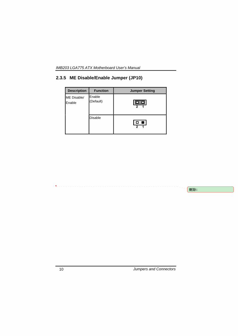
IMB203 LGA775 ATX Motherboard Userrsquos Manual
Jumpers and Connectors 12
IMB203 LGA775 ATX Motherboard Userrsquos Manual
Jumpers and Connectors 13
241 VGA Connector (CN1) The board supports CRT VGA with a 15-pin D-Sub connector for the CRT VGA display
Pin Signal Pin Signal Pin Signal 1 Red 2 Green 3 Blue 4 NA 5 GND 6 GND 7 GND 8 GND 9 VCC 10 GND 11 NA 12 DDC DATA
13 Horizontal Sync 14 Vertical Sync 15 DDC CLK
242 COM1 Connector (CN2) The board has the onboard serial port COM1 (CN2) a 9-pin D-Sub connector on the rear IO to support RS-232422485 with jumper selectable RS-485 with auto-flow control
Pin Signal 1 DCD Data carrier detect 2 RXD Receive data 3 TXD Transmit data 4 DTR Data terminal ready 5 GND ground 6 DSR Data set ready 7 RTS Request to send 8 CTS Clear to send 9 RI Ring indicator
IMB203 LGA775 ATX Motherboard Userrsquos Manual
Jumpers and Connectors 14
243 COM2~COM4 Connectors (CN16 CN19 CN25) The board has the onboard serial ports COM2~4 (CN16 CN19 CN25) three 25-pin 254 pitch box-header to support RS-232
Pin Signal Pin Signal
1 Data Carrier Detect (DCD) 2 Data Set Ready
(DSR)
3 Receive Data (RXD) 4 Request to Send
(RTS)
5 Transmit Data (TXD) 6 Clear to Send
(CTS)
7 Data Terminal Ready (DTR) 8 Ring Indicator (RI)
9 Ground (GND) 10 NC
244 Audio Connector (CN3)
Color Signal
Green LINE_OUT
Red MIC_IN
IMB203 LGA775 ATX Motherboard Userrsquos Manual
Jumpers and Connectors 15
245 PS2 KeyboardMouse Connector (CN4) The board supports a keyboard and Mouse interface
Pin Signal Pin Signal
1 KB Data 7 MS Data
2 NC 8 NC
3 GND 9 GND
4 VCC 10 VCC
5 KB CLK 11 MS CLK
6 NC 12 NC
246 Print Port Connector (CN5)
Print Port Connector This board has a multi-mode parallel port to support the following modes 1 Standard Mode
IBM PCXT PCAT and PS2trade are compatible with bi-directional parallel port
2 Enhanced Mode Enhanced parallel port (EPP) is compatible with EPP 17 and EPP 19 (IEEE 1284 compliant)
3 High Speed Mode Microsoft and Hewlett Packard extended capabilities port (ECP) is IEEE 1284 compliant
Please refer to next page for the list of pin assignment
IMB203 LGA775 ATX Motherboard Userrsquos Manual
Jumpers and Connectors 16
Print Port Pin Assignment (Default)
Pin Signal 1 Data Carrier Detect (DCD) 2 Data Set Ready (DSR)
3 Receive Data (RXD)
4 Request to Send (RTS) 5 Transmit Data (TXD)
6 Clear to Send (CTS)
7 Data Terminal Ready (DTR) 8 Ring Indicator (RI)
9 Ground (GND)
247 USB Port Connector (CN6 CN7) The Universal Serial Bus (USB) port connector on the board is for the installation of peripherals supporting the USB interface The CN6CN7 consists of two 4-pin standard USB ports
Pin Signal
1 5 USB Vcc
2 6 USB -
3 7 USB +
4 8 USB GND
IMB203 LGA775 ATX Motherboard Userrsquos Manual
Jumpers and Connectors 17
248 USB Connectors (CN27 CN29 CN33 CN45) The 10-pin standard Universal Serial Bus (USB) connectors CN27293345 on this board are for installing versatile USB interface peripherals
Pin Signal Pin Signal 1 USB 2 USB
3 USB2- 4 USB3-
5 USB2+ 6 USB3+
7 GND 8 GND
9 GND 10 GND
CN45
Pin Signal Pin Signal 1 USB 2 USB
3 USB4- 4 USB5-
5 USB4+ 6 USB5+
7 GND 8 GND
10 GND
CN27 CN29 CN33
249 ATX 4 Pin 12V In Connector (CN14) You can connect it to the ATX12V power supply for CPU Core Voltage
Pin Signal 1 GND 2 GND 3 +12V 4 +12V
IMB203 LGA775 ATX Motherboard Userrsquos Manual
Jumpers and Connectors 18
2410 Digital IO Port (DIO) Connector (CN26) The board is equipped an 8-channel digital IO connector CN26 that meets requirements for a system customary automation control The digital IO can be configured to control cash drawers sense warning signals from an Uninterrupted Power System (UPS) or perform store security control The digital IO is controlled via software programming
Pin Signal Pin Signal
1 DO1 2 DI1
3 DO2 4 DI2
5 DO3 6 DI3
7 DO4 8 DI4
9 GND 10 GND
2411 CPU Fan Connector (CN31) A CPU fan is always needed for cooling CPU heat The CPU fan connector provides power to the CPU fan
Pin Signal 1 Ground 2 +12V 3 Rotation Detection4 Speed Control
2412 SATA Connectors (CN36 CN37 CN41 CN42
CN46 CN47) These SATA connectors are for high-speed SATA interface ports and they can be connected to hard disk devices
Pin Signal
1 GND
2 SATA_TX+
3 SATA_TX-
CN364146
IMB203 LGA775 ATX Motherboard Userrsquos Manual
Jumpers and Connectors 19
4 GND
5 SATA_RX-
6 SATA_RX+
7 GND
IMB203 LGA775 ATX Motherboard Userrsquos Manual
Jumpers and Connectors 20
2413 ATX Power Connector (CN50) Steady and sufficient power can be supplied to all components on the board by connecting the power connector Please make sure all components and devices are properly installed before connecting the power connector If you use a 24-pin ATX power supply please remove the small cover from the power connector before plugging in the power cord otherwise please do not remove it Pin Signal Pin Signal 1 33V 2 33V
3 GND 4 5V
5 GND 6 5V
7 GND 8 PWR
9 5VSB 10 12V
11 12V 12 33V
13 33V 14 -12V
15 GND 16 PS_ON
17 GND 18 GND
19 GND 20 -5V
21 5V 22 5V
23 5V 24 GND
IMB203 LGA775 ATX Motherboard Userrsquos Manual
Jumpers and Connectors 21
2414 Front Panel Connector (CN52)
Power LED
This 3-pin connector denoted as Pin 1 and Pin 5 connects the system power LED indicator to such a switch on the case Pin 1 is assigned as + and Pin 5 as - The Power LED lights up when the system is powered ON Pin 3 is defined as GND
External Speaker and Internal Buzzer Connector
Pin 2 4 6 and 8 can be connected to the case-mounted speaker unit or internal buzzer While connecting the CPU card to an internal buzzer please short pins 2-4 while connecting to an external speaker you need to set pins 2-4 to Open and connect the speaker cable to pin 8 (+) and pin 2 (-)
ATX Power OnOff Button
This 2-pin connector denoted as Pin 9 and 10 connects the front panelrsquos ATX power button to the CPU card which allows users to control ATX power supply to be power onoff
System Reset Switch
Pin 11 and 12 can be connected to the case-mounted reset switch that reboots your computer instead of turning OFF the power switch It is a better way to reboot your system for a longer life of the systemrsquos power supply
HDD Activity LED
This connection is linked to hard drive activity LED on the control panel LED flashes when HDD is being accessed Pin 13 and 14 connect the hard disk drive to the front panel HDD LED Pin 13 assigned as - and Pin 14 as +
IMB203 LGA775 ATX Motherboard Userrsquos Manual
Jumpers and Connectors 22
MEMO
IMB203 LGA775 ATX Motherboard Userrsquos Manual
Hardware Installation 23
CHAPTER 3 HARDWARE INSTALLATION
Before installing the processor please access Intelreg website for more detailed information httpwwwintelcom
31 Installing the Processor The LGA775 processor socket comes with a cover to protect the processor Please install the processor into the CPU socket step by step as below
Hold the hook (A) of the lever and push it down Pull the lever (B) aside to unlock the cover
IMB203 LGA775 ATX Motherboard Userrsquos Manual
Hardware Installation 24
Remove the plastic cap (E) from the cover
Open the cover (C) you can see the contact
Be careful not to touch the contact (D)
IMB203 LGA775 ATX Motherboard Userrsquos Manual
Hardware Installation 25
Place the CPU down into the socket Be careful not to touch the contact
Hold the edges of the CPU and orientate it as the marked direction (G) down into the socket to match the (H) and (F) locations
IMB203 LGA775 ATX Motherboard Userrsquos Manual
Hardware Installation 26
Slightly push down the cover and hook the lever (I~J) The CPU is completely locked
Orientate the CPU cooling fan to fixing holes on the board
IMB203 LGA775 ATX Motherboard Userrsquos Manual
Hardware Installation 27
Screw the CPU cooling fan onto the board
Make sure the CPU fan is plugged to the CPU fan connector
IMB203 LGA775 ATX Motherboard Userrsquos Manual
Hardware Installation 28
32 Installing the Memory The board supports four 240-pin DDR3 DIMM memory sockets with maximum memory capacity up to 16GB Please follow steps below to install the memory modules 1 Push down latches on each side of the DIMM socket 2 Align the memory module with the socket that notches of
memory module must match the socket keys for a correct installation
3 Install the memory module into the socket and push it firmly down until it is fully seated The socket latches are levered upwards and clipped on to the edges of the DIMM
4 Install any remaining DIMM modules
IMB203 LGA775 ATX Motherboard Userrsquos Manual
Hardware Description 29
CHAPTER 4 HARDWARE DESCRIPTION
41 Microprocessors The IMB203 Series supports Intelreg Coretrade 2 Quad Coretrade 2 Duo processors which make your system operated under Windowsreg XP and Linux environments The system performance depends on the microprocessor Make sure all correct settings are arranged for your installed microprocessor to prevent the CPU from damages
42 BIOS The IMB203 Series uses AMI Plug and Play BIOS with a single 32Mbit SPI Flash
43 System Memory The IMB203 Series supports four 240-pin DDR3 DIMM sockets for a maximum memory of 16GB DDR3 SDRAMs The memory module can come in sizes of 1GB 2GB and 4GB
IMB203 LGA775 ATX Motherboard Userrsquos Manual
Hardware Description 30
44 IO Port Address Map The Intelreg Coretrade 2 Extreme Intelreg Coretrade 2 Quad Coretrade 2 Duo CPUs can communicate via IO ports There are total 1KB port addresses available for assignment to other devices via IO expansion cards
Address Devices 000-01F DMA controller 1
020-02D 024-025 028-029 02C-02D Interrupt controller 1
02E-02F Forwarded to LPC(LPC Super IO ) 030-031 034-035 038-039 03C-03D
Interrupt controller 2
040-043 050-053 TimerCounter (8254) 060 Forwarded to LPC (Microcontroller) 061 NMI
062-066 Forwarded to LPC (Microcontroller) 070-077 Real time clock NMI 080-091 DMA page register
092 Processor IF(Reset Generator) 093-09F DMA page register 0A0-0BF Interrupt controller 2 0C0-0DF DMA controller 2
0F0 Processor IF 0F8-0FF Math processor 170-177 Forward to SATA (SATA Controller) 1F0-1F7 Forward to SATA (SATA Controller)
376 Forward to SATA(SATA Controller) 378-37F Parallel Port (LPT) 380-38F SDLC 2 3A0-3AF SDLC 1 3B0-3BF MDA video card
(to be continued)
IMB203 LGA775 ATX Motherboard Userrsquos Manual
Hardware Description 31
Address Devices 3C0-3CF EGA card 3D0-3DF CGA card
3F6 Forward to SATA(SATA Controller) 3F8-3FF Serial port 1 (COM1) 2F8-2FF Serial port 2 (COM2)
45 Interrupt Controller (IRQ) Map The IMB203 Series is a 100 PC compatible control board It consists of 16 interrupt request lines and four out of them can be programmable The mapping list of the 16 interrupt request lines is shown as the following table
IRQ Parity check error IRQ0 System Timer Output
IRQ1 Keyboard
IRQ2 Interrupt rerouting from IRQ8 through IRQ15
IRQ3 Serial port 2
IRQ4 Serial port 1
IRQ5 PCI Device Share
IRQ7 Parallel port
IRQ8 Real time clock
IRQ9 ACPI Controller
IRQ10 PCI Device Share
IRQ11 PCI Device Share
IRQ12 PS2 Mouse
IRQ13 Math coprocessor
IRQ14 SATA Primary (Legacy Mode)
IRQ15 SATA Secondary (Legacy Mode)
IMB203 LGA775 ATX Motherboard Userrsquos Manual
Hardware Description 32
MEMO
IMB203 LGA775 ATX Motherboard Userrsquos Manual
AMI BIOS Setup Utility 33
CHAPTER 5 AMI BIOS SETUP UTILITY
This chapter provides users with detailed description how to set up basic system configuration through the AMIBIOS8 BIOS setup utility 51 Starting To enter the setup screens follow the steps below 1 Turn on the computer and press the ltDelgt key immediately 2 After you press the ltDeletegt key the main BIOS setup menu
displays You can access the other setup screens from the main BIOS setup menu such as the Chipset and Power menus
52 Navigation Keys The BIOS setuputility uses a key-based navigation system called hot keys Most of the BIOS setup utility hot keys can be used at any time during the setup navigation process These keys include ltF1gt ltF10gt ltEntergt ltESCgt ltArrowgt keys and so on
Note Some of navigation keys differ from one screen to another
IMB203 LGA775 ATX Motherboard Userrsquos Manual
AMI BIOS Setup Utility 34
LeftRight The Left ltArrowgt keys allow you to select a setup screen
UpDown The Up and Down ltArrowgt keys allow you to select a setup screen or sub-screen
+minus PlusMinus The Plus and Minus ltArrowgt keys allow you to change the field value of a particular setup item
Tab The ltTabgt key allows you to select setup fields
F1 The ltF1gt key allows you to display the General Help screen
F10 The ltF10gt key allows you to save any changes you have made and exit Setup Press the ltF10gt key to save your changes
Esc
The ltEscgt key allows you to discard any changes you have made and exit the Setup Press the ltEscgt key to exit the setup without saving your changes
Enter
The ltEntergt key allows you to display or change the setup option listed for a particular setup item The ltEntergt key can also allow you to display the setup sub- screens
IMB203 LGA775 ATX Motherboard Userrsquos Manual
AMI BIOS Setup Utility 35
53 Main Menu When you first enter the Setup Utility you will enter the Main setup screen You can always return to the Main setup screen by selecting the Main tab There are two Main Setup options They are described in this section The Main BIOS Setup screen is shown below
System TimeDate
Use this option to change the system time and date Highlight System Time or System Date using the ltArrowgt keys Enter new values through the keyboard Press the ltTabgt key or the ltArrowgt keys to move between fields The date must be entered in MMDDYY format The time is entered in HHMMSS format
IMB203 LGA775 ATX Motherboard Userrsquos Manual
AMI BIOS Setup Utility 36
54 Advanced Menu The Advanced menu allows users to set configuration of the CPU and other system devices You can select any of the items in the left frame of the screen to go to the sub menus
CPU Configuration IDE Configuration SuperIO Configuration Hardware Health Configuration ACPI Configuration AHCI Configuration Intel iAMT Configuration Intel VT-d Configuration MPS Configuration PCI Express Configuration Trusted Computing USB Configuration
For items marked with ldquo rdquo please press ltEntergt for more options
IMB203 LGA775 ATX Motherboard Userrsquos Manual
AMI BIOS Setup Utility 37
CPU Configuration This screen shows the CPU Configuration and you can change the value of the selected option
Max CPUID Value Limit
You can enable this item to let legacy operating systems boot even without support for CPUs with extended CPU ID functions
Execute-Disable Bit Capability This item helps you enable or disable the No-Execution Page Protection Technology
Core Multi-Processing This feature controls the functionality of the Core Multi-Processing to allow the processor to execute multitasking function
PECI Use this item PECI (Platform Environment Control Interface) to execute the processor temperature monitoring and management
IMB203 LGA775 ATX Motherboard Userrsquos Manual
AMI BIOS Setup Utility 38
Intel (R) C-STATE tech Use this item to enable or disable the C-State technology
IDE Configuration You can use this screen to select options for the IDE Configuration and change the value of the selected option A description of the selected item appears on the right side of the screen For items marked with ldquo rdquo please press ltEntergt for more options
SATA1 Configuration
Use this item to control the onboard SATA controller Here are the options for your selection Compatible Disabled and Enhanced
Configure SATA1 as Use this item to choose the SATA operation mode Here are the options for your selection IDE and AHCI
SATA2 Configuration Use this item to control the onboard SATA controller Here are the options for your selection Enhanced and Disabled
IMB203 LGA775 ATX Motherboard Userrsquos Manual
AMI BIOS Setup Utility 39
PrimarySecondaryThird IDE Master Select one of the hard disk drives to configure IDE devices installed in the system by pressing ltEntergt for more options
Fifth IDE Master Select one of the hard disk drives to configure IDE devices installed in the system by pressing ltEntergt for more options
IMB203 LGA775 ATX Motherboard Userrsquos Manual
AMI BIOS Setup Utility 40
SuperIO Configuration You can use this screen to select options for the SuperIO Configuration and change the value of the selected option A description of the selected item appears on the right side of the screen
Serial Port1 Address
This option specifies the base IO port address and Interrupt Request address of serial port 1 The Optimal setting is 3F8IRQ4 The Fail-Safe default setting is Disabled
Serial Port2 Address This option specifies the base IO port address and Interrupt Request address of serial port 2 The Optimal setting is 2F8IRQ3 The Fail-Safe setting is Disabled
Parallel Port Address This item allows you to determine the IO address for onboard parallel port There are several options for your selection
Parallel Port Mode
IMB203 LGA775 ATX Motherboard Userrsquos Manual
AMI BIOS Setup Utility 41
Select an operating mode for the onboard parallel (printer) port
Parallel Port IRQ Use this item to set up the IRQ for onboard parallel port
Serial Port3 Address This item specifies the base IO port address and Interrupt Request address of serial port 3 The Optimal setting is 3E8IRQ11 The Fail-Safe default setting is Disabled
Serial Port3 IRQ This item specifies the IRQ used by the serial port 3
Serial Port4 Address This item specifies the base IO port address and Interrupt Request address of serial port 4 The Optimal setting is 2E8IRQ10 The Fail-Safe default setting is Disabled
Serial Port4 IRQ This item specifies the IRQ used by the serial port 4
IMB203 LGA775 ATX Motherboard Userrsquos Manual
AMI BIOS Setup Utility 42
Hardware Health Configuration This screen shows the Hardware Health Configuration and a description of the selected item appears on the right side of the screen
HW Health Configuration
This screen displays the temperature of CPU and System Fan Speed Vcore etc
IMB203 LGA775 ATX Motherboard Userrsquos Manual
AMI BIOS Setup Utility 43
ACPI Configuration You can use this screen to select options for the ACPI Configuration and change the value of the selected option A description of the selected item appears on the right side of the screen
General ACPI Configuration
Scroll to this item and press ltEntergt to view the General ACPI Configuration sub menu which contains General ACPI (Advanced Configuration and Power Management Interface) options for your configuration
Advanced ACPI Configuration Scroll to this item and press ltEntergt to view the Advanced ACPI Configuration sub menu which contains Advanced ACPI (Advanced Configuration and Power Management Interface) options for your configuration
Chipset ACPI Configuration Scroll to this item and press ltEntergt to view the Chipset ACPI Configuration sub menu which contains Chipset ACPI (Advanced Configuration and Power Management
IMB203 LGA775 ATX Motherboard Userrsquos Manual
AMI BIOS Setup Utility 44
Interface) options for your configuration AHCI Configuration
You can use this screen to select options for the AHCI Configuration and change the value of the selected option A description of the selected item appears on the right side of the screen
AHCI BIOS Support You can enable or disable this item to control the AHCI function of the SATA controller
IMB203 LGA775 ATX Motherboard Userrsquos Manual
AMI BIOS Setup Utility 45
Intel iAMT Configuration You can use this screen to select options for the Intel iAMT Configuration and change the value of the selected option A description of the selected item appears on the right side of the screen
Intel iAMT Support
You can enable this item to support iAMT (active management technology) function to follow up the procedure for the access to AMI program screen
Unconfigure iAMTME Use this item to unconfigure the iAMTME settings
IMB203 LGA775 ATX Motherboard Userrsquos Manual
AMI BIOS Setup Utility 46
Intel VT-d Configuration You can use this screen to select options for the Intel VT-d Configuration and change the value of the selected option A description of the selected item appears on the right side of the screen
Intel VT-d Virtualization Technology for Directed IO (VT-d) extends Virtualization Technology (VT) roadmap by providing hardware assists for virtualization solution VT-d can help end users improve security and reliability of the systems and also improve performance of IO devices in virtualized environment Here are the options for your selection Disabled and Enabled
IMB203 LGA775 ATX Motherboard Userrsquos Manual
AMI BIOS Setup Utility 47
Remote Access Configuration You can use this screen to select options for the Remote Access Configuration and change the value of the selected option A description of the selected item appears on the right side of the screen
Remote Access Use this item to enable or disable the Remote Access function
IMB203 LGA775 ATX Motherboard Userrsquos Manual
AMI BIOS Setup Utility 48
PCI Express Configuration This screen shows the PCI Express Configuration and you can change its value A description of the selected item appears on the right side of the screen
Active State Power-Management
Use this item to enable or disable the function of Active State Power-Management to provide you with lower power consumption The default setting is Disabled
IMB203 LGA775 ATX Motherboard Userrsquos Manual
AMI BIOS Setup Utility 49
Trusted Computing You can use this screen to select options for the Trusted Computing and change the value of the selected option A description of the selected item appears on the right side of the screen
TCGTPM SUPPORT Use this item to control the Trusted Platform Module (TPM) function
IMB203 LGA775 ATX Motherboard Userrsquos Manual
AMI BIOS Setup Utility 50
USB Configuration You can use this screen to select options for the USB Configuration and change the value of the selected option A description of the selected item appears on the right side of the screen
USB Functions
This item allows you to enable or disable USB functions
Legacy USB Support Use this item to enable or disable support for USB device on legacy operating system The default setting is Enabled
USB 20 Controller Mode Use this item to configure the USB 20 controller The default setting is HiSpeed
BIOS EHCI Hand-Off Enabling this item provide the support for operating systems without an EHCI hand-off feature The default setting is Enabled
IMB203 LGA775 ATX Motherboard Userrsquos Manual
AMI BIOS Setup Utility 51
IMB203 LGA775 ATX Motherboard Userrsquos Manual
AMI BIOS Setup Utility 52
55 PCI PnP Menu The PCI PnP menu allows users to change the advanced settings for PCIPnP devices
Clear NVRAM
Use this item to clear the data in the NVRAM (CMOS) Here are the options for your selection No and Yes
Plug amp Play OS When the setting is No Use this item to configure all the devices in the system When the setting is Yes and if you install a Plug and Play operating system the operating system configures the Plug and Play devices not required for boot The default setting is No
IMB203 LGA775 ATX Motherboard Userrsquos Manual
AMI BIOS Setup Utility 53
PCI Latency Timer This item controls how long a PCI device can hold the PCI bus before another takes over The longer the latency the longer the PCI device can retain control of the bus before handing it over to another PCI device There are several options for your selection
Allocate IRQ to PCI VGA This item allows BIOS to choose an IRQ to assign for the PCI VGA card Here are the options for your selection No and Yes
Palette Snooping Some old graphic controllers need to ldquosnooprdquo on the VGA palette and then map it to their display as a way to provide boot information and VGA compatibility This item allows such snooping to take place Here are the options for your selection Disabled and Enabled
PCI IDE BusMaster This item is a toggle for the built-in driver that allows the onboard IDE controller to perform DMA (Direct Memory Access) transfer Here are the options for your selection Disabled and Enabled
OffBoard PCIISA IDE Card This item is for any other non-onboard PCIISA IDE controller adapter There are several options for your selection
IRQ3457910111415 These items will allow you to assign each system interrupt a type depending on the type of device using the interrupt The option ldquoAvailablerdquo means the IRQ is going to assign automatically Here are the options for your selection Available and Reserved
DMA Channel 013567 These items will allow you to assign each DMA channel a type depending on the type of device using the channel The option ldquoAvailablerdquo means the channel is going to assign automatically Here are the options for your selection Available and Reserved
IMB203 LGA775 ATX Motherboard Userrsquos Manual
AMI BIOS Setup Utility 54
56 Boot Menu The Boot menu allows users to change boot options of the system You can select any of the items in the left frame of the screen to go to the sub menus
Boot Settings Configuration Boot Device Priority Removable Drives
For items marked with ldquo rdquo please press ltEntergt for more options
IMB203 LGA775 ATX Motherboard Userrsquos Manual
AMI BIOS Setup Utility 55
Boot Settings Configuration
Quick Boot
Enabling this item lets the BIOS skip some power on self tests (POST) The default setting is Enabled
AddOn ROM Display Mode This item selects the display mode for option ROM The default setting is Force BIOS
Boot Num-Lock Use this item to select the power-on state for the NumLock The default setting is On
PS2 Mouse Support This item determines if the BIOS should reserve IRQ12 for the PS2 mouse or allow other devices to make use of this IRQ Here are the options for your selection Auto Enabled and Disabled
Wait For lsquoF1rsquo Of Error If this item is enabled the system waits for the F1 key to be pressed when error occurs The default setting is Enabled
Hit lsquoDELrsquo Message Display If this item is enabled the system displays the message
IMB203 LGA775 ATX Motherboard Userrsquos Manual
AMI BIOS Setup Utility 56
ldquoPress DEL to run Setuprdquo during POST The default setting is Enabled
Interrupt 19 Capture If this item is enabled this function makes the option ROMs to trap Interrupt 19 The default setting is Disabled
Boot Device Priority The Boot Device Priority screen specifies the boot device priority sequence from the available devices
IMB203 LGA775 ATX Motherboard Userrsquos Manual
AMI BIOS Setup Utility 57
Removable Drives Use this screen to view the removable drives in the system The BIOS will attempt to arrange the removable drive boot sequence automatically You can also change the booting sequence
IMB203 LGA775 ATX Motherboard Userrsquos Manual
AMI BIOS Setup Utility 58
57 Security Menu The Security menu allows users to change the security settings for the system
Supervisor Password
This item indicates whether a supervisor password has been set If the password has been installed Installed displays If not Not Installed displays
User Password This item indicates whether a user password has been set If the password has been installed Installed displays If not Not Installed displays
Change Supervisor Password Select this option and press ltEntergt to access the sub menu You can use the sub menu to change the supervisor password
Change User Password Select this option and press ltEntergt to access the sub menu You can use the sub menu to change the user password
IMB203 LGA775 ATX Motherboard Userrsquos Manual
AMI BIOS Setup Utility 59
58 Chipset Menu The Chipset menu allows users to change the advanced chipset settings You can select any of the items in the left frame of the screen to go to the sub menus
North Bridge Configuration South Bridge Configuration ME Subsystem Configuration
For items marked with ldquo rdquo please press ltEntergt for more options
IMB203 LGA775 ATX Motherboard Userrsquos Manual
AMI BIOS Setup Utility 60
North Bridge Configuration
Memory Remap Feature
Use this item to enable or disable the remapping of the overlapped PCI memory above the total physical memory Only 64-bit OS supports this function
DRAM Frequency This item allows you to control the Memory Clock
Configure DRAM Timing by SPD This item can enable or disable DRAM timing by SPD (Serial Presence Detect) device which is a small EEPROM chip on the memory module containing important information about the module speed size addressing mode and various parameters
Memory Hole You can reserve this area of system memory for ISA adapter ROM When this area is reserved it cannot be cached Check the user information of peripherals that need to use this area o f system memory for the memory requirements Here are the options Disabled and 15M-16M
IMB203 LGA775 ATX Motherboard Userrsquos Manual
AMI BIOS Setup Utility 61
Initiate Graphic Adapter When using multiple graphics cards this item can select which graphics controller to be the primary display device during boot
IGD Graphics Mode Select This item allows you to select the amount of system memory used by the internal graphics device
PEG Port ConfigurationPEG Port This item is a toggle to enable or disable the PCI Express port Here are the options for your selection Auto and Disabled
Video Function Configuration Press ltEntergt for the sub-menu for setting up video function
IMB203 LGA775 ATX Motherboard Userrsquos Manual
AMI BIOS Setup Utility 62
South Bridge Configuration
GbE Wake Up From S5 This item specifies whether the system will be awakened from the S5 power
HDA Controller This item allows you to enable or disable the HD audio support
Restore on AC Power Loss This item can control how the PC will behave once power is restored following a power outage or other unexpected shutdown
PCIE Port Configuration This item allows you to set or disable the PCI Express Ports
IMB203 LGA775 ATX Motherboard Userrsquos Manual
AMI BIOS Setup Utility 63
ME Subsystem Configuration
It is strongly recommended that you do not modify these options unless you are an advanced user
IMB203 LGA775 ATX Motherboard Userrsquos Manual
AMI BIOS Setup Utility 64
59 Exit Menu The Exit menu allows users to load your system configuration with optimal or failsafe default values
Save Changes and Exit
When you have completed the system configuration changes select this option to leave Setup and reboot the computer so the new system configuration parameters can take effect Select Save Changes and Exit from the Exit menu and press ltEntergt Select Ok to save changes and exit
Discard Changes and Exit Select this option to quit Setup without making any permanent changes to the system configuration Select Discard Changes and Exit from the Exit menu and press ltEntergt Select Ok to discard changes and exit
Load Optimal Defaults It automatically sets all Setup options to a complete set of default settings when you select this option The Optimal settings are designed for maximum system performance but may not work best for all computer applications In particular do not use the Optimal Setup options if your
IMB203 LGA775 ATX Motherboard Userrsquos Manual
AMI BIOS Setup Utility 65
computer is experiencing system configuration problems Select Load Optimal Defaults from the Exit menu and press ltEntergt
Load Fail-Safe Defaults It automatically sets all Setup options to a complete set of default settings when you select this option The Fail-Safe settings are designed for maximum system stability but not maximum performance Select the Fail-Safe Setup options if your computer is experiencing system configuration problems Select Load Fail-Safe Defaults from the Exit menu and press ltEntergt Select Ok to load Fail-Safe defaults
IMB203 LGA775 ATX Motherboard Userrsquos Manual
AMI BIOS Setup Utility 66
MEMO
IMB203 LGA775 ATX Motherboard Userrsquos Manual
Installation of Drivers 67
CHPATER 6 INSTALLATION OF DRIVERS
The device drivers are located on the Product Information CD-ROM that comes with the IMB203 Series package The auto-run function of drivers will guide you to install the utilities and device drivers under a Windows system You can follow the onscreen instructions to install these devices
Chipse VGA LAN Audio iAMT MEI
61 Installing Chipset Driver 1 Run the SETUPEXE program from the driver directory in
your driver CD Click ldquoNextrdquo to next step
IMB203 LGA775 ATX Motherboard Userrsquos Manual
Installation of Drivers 68
2 An Intelreg License Agreement appears to show you the important information Click ldquoYesrdquo to next step
3 Refer to the Readme file below to view the system requirements and installation information
IMB203 LGA775 ATX Motherboard Userrsquos Manual
Installation of Drivers 69
3-1 Please wait while running the following setup operations
3-2 Please wait while running the following setup operations
IMB203 LGA775 ATX Motherboard Userrsquos Manual
Installation of Drivers 70
4 Click ldquoFinishrdquo to complete the setup process
5 You will be asked to reboot your computer when the installation is completed Please click ldquoYes I want to restart my computer nowrdquo if you donrsquot need to install any other drivers Otherwise please click ldquoNo I will restart my computer laterrdquo and go on next step
IMB203 LGA775 ATX Motherboard Userrsquos Manual
Installation of Drivers 71
62 Installing VGA Driver 1 Run the SETUPEXE program from the driver directory in
your driver CD Click ldquoNextrdquo to next step
2 An Intelreg License Agreement appears to show you the
important information Click ldquoYesrdquo to next step
IMB203 LGA775 ATX Motherboard Userrsquos Manual
Installation of Drivers 72
3 The message of Readme File Information appears to show you the system requirements and installation information Please click ldquoNextrdquo
4 Please wait while running the following setup operations
When this message appears please click ldquoNextrdquo
IMB203 LGA775 ATX Motherboard Userrsquos Manual
Installation of Drivers 73
5 Click ldquoFinishrdquo to complete the setup process
6 You will be asked to reboot your computer when the installation is completed Please click ldquoYes I want to restart my computer nowrdquo if you donrsquot need to install any other drivers Otherwise please click ldquoNo I will restart my computer laterrdquo and click ldquoFinishrdquo to complete the installation
IMB203 LGA775 ATX Motherboard Userrsquos Manual
Installation of Drivers 74
63 Installing LAN Driver
11 Run the InstallShield Wizard for Network Connections from
the driver directory in your driver CD Click ldquoNextrdquo to next step
IMB203 LGA775 ATX Motherboard Userrsquos Manual
Installation of Drivers 75
12 An Intelreg License Agreement appears to show you the important information Click ldquoYesrdquo to next step
13 A Setup Options window appears that you can select the
program features you want to install
IMB203 LGA775 ATX Motherboard Userrsquos Manual
Installation of Drivers 76
2 Click ldquoInstallrdquo to start the installation
3 Please wait while running the following installation operation
IMB203 LGA775 ATX Motherboard Userrsquos Manual
Installation of Drivers 77
4 Click ldquoFinishrdquo to complete the installation
Note The Driver item [Wake on Directed Packet] default is Enabled under Windows Vista
格式化 字型 (符號) Arial
格式化 字型 (符號) Arial
格式化 字型 斜體 字型色彩 黑色 (符號) Arial 非加寬 緊縮
格式化 字型 斜體 字型色彩 黑色 (符號) Arial 非加寬 緊縮
格式化 字型 (符號) Arial 非加寬 緊縮
IMB203 LGA775 ATX Motherboard Userrsquos Manual
Installation of Drivers 78
64 Installing AUDIO Driver 1 Run the InstallShield Wizard for Realtek High Definition
Audio Driver from the driver directory in your driver CD Click ldquoNextrdquo to next step
IMB203 LGA775 ATX Motherboard Userrsquos Manual
Installation of Drivers 79
2 Click ldquoInstallrdquo to start the installation and wait while running the installation operation
3 Click ldquoFinishrdquo to complete the installation
IMB203 LGA775 ATX Motherboard Userrsquos Manual
Installation of Drivers 80
65 Installing iAMT (Active Management Technology) Driver
Note You must download and properly install the required NET version 35 provided from a separate downloading of the actual FimwareTools kit releases posted on VIP prior to loading the MEILMS Driver stack
651 LMS_SOL Setup
1 Run the setup program to install Intelreg Active Management Technology onto your computer It is strongly recommended that you exit all programs before continuing Click ldquoNextrdquo to next step
格式化 字型 (符號) Arial
格式化 字型 (符號) Arial 非加寬 緊縮
IMB203 LGA775 ATX Motherboard Userrsquos Manual
Installation of Drivers 81
2 An Intelreg license agreement appears that you need to continue the setup program by clicking ldquoYesrdquo to accept the terms
IMB203 LGA775 ATX Motherboard Userrsquos Manual
Installation of Drivers 82
3 Refer to the Readme file below to view the system requirements and installation information Click ldquoNextrdquo to next setup
4 Please wait while running the following installation operation
IMB203 LGA775 ATX Motherboard Userrsquos Manual
Installation of Drivers 83
5 Click ldquoFinishrdquo to complete the installation
IMB203 LGA775 ATX Motherboard Userrsquos Manual
Installation of Drivers 84
652 LMS_SOL_IS Setup
1 Run the setup program to install Intelreg Active Management Technology onto your computer It is strongly recommended that you exit all programs before continuing Click ldquoNextrdquo to next step
IMB203 LGA775 ATX Motherboard Userrsquos Manual
Installation of Drivers 85
2 An Intelreg license agreement appears that you need to continue the setup program by clicking ldquoYesrdquo to accept the terms
IMB203 LGA775 ATX Motherboard Userrsquos Manual
Installation of Drivers 86
3 Refer to the Readme file below to view the system requirements and installation information Click ldquoNextrdquo to next setup
4 Please wait while running the following installation operation
IMB203 LGA775 ATX Motherboard Userrsquos Manual
Installation of Drivers 87
5 Click ldquoFinishrdquo to complete the installation
IMB203 LGA775 ATX Motherboard Userrsquos Manual
Installation of Drivers 88
66 Installing MEI (Management Engine Interface) Driver
Note You must download and properly install the required NET version 35 provided from a separate downloading of the actual FimwareTools kit releases posted on VIP prior to loading the MEILMS Driver stack
1 Run the setup program to install Intelreg Management Engine
Interface onto your computer It is strongly recommended that you exit all programs before continuing Click ldquoNextrdquo to next step
格式化 字型 (符號) Arial
格式化 字型 (符號) Arial 非加寬 緊縮
IMB203 LGA775 ATX Motherboard Userrsquos Manual
Installation of Drivers 89
2 An Intelreg license agreement appears that you need to continue the setup program by clicking ldquoYesrdquo to accept the terms
IMB203 LGA775 ATX Motherboard Userrsquos Manual
Installation of Drivers 90
3 Refer to the Readme file below to view the system requirements and installation information Click ldquoNextrdquo to next setup
4 Please wait while running the following installation operation
IMB203 LGA775 ATX Motherboard Userrsquos Manual
Installation of Drivers 91
5 Click ldquoFinishrdquo to complete the installation
IMB203 LGA775 ATX Motherboard Userrsquos Manual
Installation of Drivers 92
MEMO
IMB203 LGA775 ATX Motherboard Userrsquos Manual
Watchdog Timer 93
APPENDIX A WATCHDOG TIMER
Watchdog Timer Setting After the system stops working for a while it can be auto-reset by the Watchdog Timer The integrated Watchdog Timer can be set up in the system reset mode by program
Using the Watchdog Function Start darr Un-Lock WDT O 2E 87 Un-lock super IO
O 2E 87 Un-lock super IO darr Set WDT Function O 2E 2D O 2F 20 Select Logic device O 2E 07 O 2F 08 darr Activate WDT O 2E 30
O 2F 01 Set Second or Minute O 2E F5
O 2F N N=00 or 08(See below table) darr Set base timer O 2E F6
O 2F M=000102hellipFF(Hex) Value=0 to 255 darr WDT counting
re-set timer O 2E F6
O 2F M M=000102hellipFF(See below table) darr
格式化
格式化 項目符號及編號
格式化 項目符號及編號
格式化 字型 8 點 字型色彩黑色
格式化 字型 8 點 字型色彩黑色
格式化 定位點 1257 字元左 + 不在 1012 字元 + 1386字元
格式化 字型 8 點 字型色彩黑色
格式化 定位點 1257 字元左 + 不在 134 字元 + 1362字元
格式化 字型色彩 黑色
格式化 字型色彩 黑色
刪除
IMB203 LGA775 ATX Motherboard Userrsquos Manual
Watchdog Timer 94
IF No re-set timer WDT time-out generate RESET IF to disable WDT O 2E 30
O 2F 00 Can be disable at any time
N=00
M= 00h Time-out Disable 01h Time-out occurs after 1 second 02h Time-out occurs after 2 second 03h Time-out occurs after 3 second helliphelliphelliphelliphelliphelliphelliphelliphellip FFh Time-out occurs after 255 second
N=08
M= 00h Time-out Disable 01h Time-out occurs after 1 minute 02h Time-out occurs after 2 minutes 03h Time-out occurs after 3 minutes helliphelliphelliphelliphelliphelliphelliphelliphellip
FFh Time-out occurs after 255 minutes
格式化 字型色彩 黑色
格式化 字型色彩 黑色
IMB203 LGA775 ATX Motherboard Userrsquos Manual
PCI IRQ Routing 95
APPENDIX B PCI IRQ ROUTING
PICMG PCI IRQ Routing
Device ID Slot Int
PCI Slot 0 31 0 BCDA PCI Slot 1 30 1 CDAB PCI Slot 2 29 2 DABC PCI Slot 3 28 3 ABCD
IMB203 LGA775 ATX Motherboard Userrsquos Manual
PCI IRQ Routing 96
MEMO
IMB203 LGA775 ATX Motherboard Userrsquos Manual
Configuring SATA for RAID Function 97
APPENDIX C CONFIGURING SATA FOR RAID
FUNCTION
Configuring SATA Hard Drive(s) for RAID Function (Controller IntelregICH10DODO DH only) Please follow up the steps below to configure SATA hard drive(s) (1) Install SATA hard drive(s) in your system (2) Enter the BIOS Setup to configure SATA controller mode and boot
sequence (3) Configure RAID by the RAID BIOS (4) Install the SATA controller driver during the OS installation Before you begin the SATA configuration please prepare (a) Two SATA hard drives (to ensure optimal performance it is
recommended that you use two hard drives with identical model and capacity) If you do not want to create RAID with the SATA controller you may prepare only one hard drive
(b) An empty formatted floppy disk (c) Windows XP setup disk (1) Installing SATA hard drive(s) in your system
Connect one end of the SATA signal cable to the rear of the SATA hard drive and the other end to available SATA port(s) on the board Then connect the power connector of power supply to the hard drive
(2) Configuring SATA controller mode and boot sequence by the BIOS Setup You have to make sure whether the SATA controller is configured correctly by system BIOS Setup and set up BIOS boot sequence for the SATA hard drive(s)
IMB203 LGA775 ATX Motherboard Userrsquos Manual
Configuring SATA for RAID Function 98
(2)-1-1 Turn on your system and then press the Del button to enter BIOS Setup during running POST (Power-On Self Test) If you want to create RAID just go to the Advanced Settings menuIDE configuration select the Configure SATA1 as and press ltEntergt for more options
IMB203 LGA775 ATX Motherboard Userrsquos Manual
Configuring SATA for RAID Function 99
(2)-1-2 A list of options appears please select RAID
IMB203 LGA775 ATX Motherboard Userrsquos Manual
Configuring SATA for RAID Function 100
(2)-2 Set CDROM for First Boot Device under the Boot Settings menu to boot CD-ROM after system restarts
(2)-3 Save and exit the BIOS Setup
IMB203 LGA775 ATX Motherboard Userrsquos Manual
Configuring SATA for RAID Function 101
(3) Configuring RAID by the RAID BIOS Enter the RAID BIOS setup utility to configure a RAID array Skip this step and proceed to Section 4 if you do not want to create a RAID (3)-1 After the POST memory testing and before the operating
system booting a message Press ltCtrl-Igt to enter Configuration Utility shows up accordingly press ltCTRL+ Igt to enter the RAID BIOS setup utility
(3)-2 After you press ltCTRL+ Igt the Create RAID Volume screen will appear If you want to create a RAID array select the Create RAID Volume option in the Main Menu and press ENTER
IMB203 LGA775 ATX Motherboard Userrsquos Manual
Configuring SATA for RAID Function 102
(3)-3-1 After entering the CREATE VOLUME MENU screen you can type the disk array name with 1~16 letters (letters cannot be special characters) in the item ldquoNamerdquo
(3)-3-2 When finished press ENTER to select a RAID level There are three RAID levels RAID0 RAID1 and RAID5 amp RAID10 Select a RAID level and press ENTER
IMB203 LGA775 ATX Motherboard Userrsquos Manual
Configuring SATA for RAID Function 103
(3)-4 Set the stripe block size The KB is the standard unit of stripe block size The stripe block size can be 4KB to 128KB After the setting press ENTER for the array capacity
(3)-5 After setting all the items on the menu select Create Volume
and press ENTER to start creating the RAID array
IMB203 LGA775 ATX Motherboard Userrsquos Manual
Configuring SATA for RAID Function 104
(3)-6 When prompting the confirmation press ldquoYldquo to create this volume or ldquoNldquo to cancel the creation
After the creation is completed you can see detailed information about the RAID Array in the DISKVOLUME INFORMATION section including RAID mode disk block size disk name and disk capacity etc
IMB203 LGA775 ATX Motherboard Userrsquos Manual
Configuring SATA for RAID Function 105
Delete RAID Volume If you want to delete a RAID volume select the Delete RAID Volume option in Main Menu Press ENTER and follow on-screen instructions
Please press [ESC] to exit the RAID BIOS utility Now you can proceed to install a SATA driver controller and the operating system
IMB203 LGA775 ATX Motherboard Userrsquos Manual
Configuring SATA for RAID Function 106
(4) Making a SATA Driver Disk To install the operating system onto a serial ATA hard disk successfully you need to install the SATA controller driver during the OS installation Without the driver the hard disk may not be recognized during the Windows setup process First of all please format a blank floppy disk Secondly follow up these steps below to produce a SATA driver disk Users can insert the Driver CD and the formatted blank floppy disk in another system And then please copy all of file of the f6flpy32 folder in the Driver CD to a floppy disk Note Please copy all of file of the f6flpy64 folder if installing 64-bit
Windows Operating System
IMB203 LGA775 ATX Motherboard Userrsquos Manual
Configuring SATA for RAID Function 107
(5) Installing the SATA controller driver during the OS installation Now the SATA driver disk is ready and BIOS settings configured you can proceed to install Windows 2000XP onto your SATA hard drive using the SATA driver Here is an example for Windows XP installation (5)-1 Restart your system to boot the Windows 2000XP Setup disk
and press F6 button as soon as you see the message Press F6 if you need to install a 3rd party SCSI or RAID driver After pressing the F6 button there will be a few moments for some files being loaded before next screen appears
IMB203 LGA775 ATX Motherboard Userrsquos Manual
Configuring SATA for RAID Function 108
(5)-2 When you see the screen below insert the floppy disk containing the SATA driver and press ldquoSrdquo
(5)-3 If the Setup correctly recognizes the driver of the floppy disk
a controller menu will appear below Use the ARROW keys to select Intel(R) ICH8RICH9RICH10RDO SATA RAID Controller and press ENTER Then it will begin to load the SATA driver from the floppy disk
IMB203 LGA775 ATX Motherboard Userrsquos Manual
Configuring SATA for RAID Function 109
Note If a message on the screen saying that one or some file(s) cannot be found please check the floppy disk or copy the correct SATA driver again from the driver CD
IMB203 LGA775 ATX Motherboard Userrsquos Manual
Configuring SATA for RAID Function 110
MEMO
IMB203 LGA775 ATX Motherboard Userrsquos Manual
iAMT Settings 111
APPENDIX D iAMT SETTINGS
The Intelreg Active Management Technology (Intelreg iAMT) has decreased a major barrier to IT efficiency that uses built-in platform capabilities and popular third-party management and security applications to allow IT a better discovering healing and protection their networked computing assets In order to utilize Intel iAMT you must enter the ME BIOS (CTRL + P during system startup) change the ME BIOS password and then select ldquoIntelreg iAMTrdquo as the manageability feature
D1 Entering MEBx 1 You must go to BIOS TO start iAMT function 2 Exit from BIOS after starting iAMT and press Ctrl+P to enter MEBx Setting
It is better to press Ctrl+P before the screen popping out
格式化
IMB203 LGA775 ATX Motherboard Userrsquos Manual
iAMT Settings 112
D2 Set amp Change Password 1 You will be asked to set a password when first log in The default
password is lsquoadminrsquo
2 You will be asked to change the password before setting ME
Change Password
IMB203 LGA775 ATX Motherboard Userrsquos Manual
iAMT Settings 113
3 You must confirm your new password while revising (as Remark 1)
Remark 1 The new password must contain (example 11qqQQ) (default value)
Eight characters
One upper case
One lower case
One number
One special symbol such as $ or
( excepted)
Underline ( _ ) and space are valid characters for password but they wonrsquot make higher complexity
IMB203 LGA775 ATX Motherboard Userrsquos Manual
iAMT Settings 114
D3 Intelreg iAMT Settings 1 Select Intelreg iAMT Configuration and press ltENTERgt
2 Key in the Host Name If Intelreg iAMT set to lsquoDHCPlsquo the Host name must be identical to the operating system mechanic
IMB203 LGA775 ATX Motherboard Userrsquos Manual
iAMT Settings 115
3 Select TCPIP to get into Network interface and set it to lsquoENABLEDrsquo into DHCP Mode and set it to lsquoDISABLEDrsquo (as Remark 2) into Domain name and set the Intel Management Engine domain name such as lsquoAMTintelcomrsquo
(3-1)
(3-2)
IMB203 LGA775 ATX Motherboard Userrsquos Manual
iAMT Settings 116
Remark 2 DHCP Mode lsquoDISABLEDlsquo if DHCP Mode is disabled you can make the following settings
IP address
Subnet mask
IMB203 LGA775 ATX Motherboard Userrsquos Manual
iAMT Settings 117
Default Gateway address
Preferred DNS address
IMB203 LGA775 ATX Motherboard Userrsquos Manual
iAMT Settings 118
Alternate DNS address
Domain name
4 Exit from MEBx after completing the iAMT settings
IMB203 LGA775 ATX Motherboard Userrsquos Manual
iAMT Settings 119
D4 iAMT Web Console 1 From a web browser please type http(IP ADDRESS)16992
which connects to iAMT Web Example http1014021416992
2 To log on you will be required to type in username and password
for access to the Web
USER admin (default value)
PASS (MEBx password)
IMB203 LGA775 ATX Motherboard Userrsquos Manual
iAMT Settings 120
3 Enter the iAMT Web
4 Click Remote Control and select commands on the right side
IMB203 LGA775 ATX Motherboard Userrsquos Manual
iAMT Settings 121
5 When you have finished using the iAMT Web console close the Web browser
IMB203 LGA775 ATX Motherboard Userrsquos Manual
iAMT Settings 122
MEMO
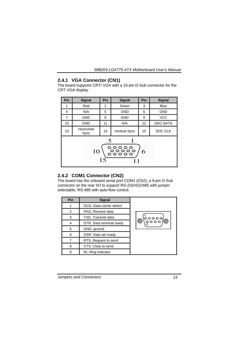
IMB203 LGA775 ATX Motherboard Userrsquos Manual
Jumpers and Connectors 14
243 COM2~COM4 Connectors (CN16 CN19 CN25) The board has the onboard serial ports COM2~4 (CN16 CN19 CN25) three 25-pin 254 pitch box-header to support RS-232
Pin Signal Pin Signal
1 Data Carrier Detect (DCD) 2 Data Set Ready
(DSR)
3 Receive Data (RXD) 4 Request to Send
(RTS)
5 Transmit Data (TXD) 6 Clear to Send
(CTS)
7 Data Terminal Ready (DTR) 8 Ring Indicator (RI)
9 Ground (GND) 10 NC
244 Audio Connector (CN3)
Color Signal
Green LINE_OUT
Red MIC_IN
IMB203 LGA775 ATX Motherboard Userrsquos Manual
Jumpers and Connectors 15
245 PS2 KeyboardMouse Connector (CN4) The board supports a keyboard and Mouse interface
Pin Signal Pin Signal
1 KB Data 7 MS Data
2 NC 8 NC
3 GND 9 GND
4 VCC 10 VCC
5 KB CLK 11 MS CLK
6 NC 12 NC
246 Print Port Connector (CN5)
Print Port Connector This board has a multi-mode parallel port to support the following modes 1 Standard Mode
IBM PCXT PCAT and PS2trade are compatible with bi-directional parallel port
2 Enhanced Mode Enhanced parallel port (EPP) is compatible with EPP 17 and EPP 19 (IEEE 1284 compliant)
3 High Speed Mode Microsoft and Hewlett Packard extended capabilities port (ECP) is IEEE 1284 compliant
Please refer to next page for the list of pin assignment
IMB203 LGA775 ATX Motherboard Userrsquos Manual
Jumpers and Connectors 16
Print Port Pin Assignment (Default)
Pin Signal 1 Data Carrier Detect (DCD) 2 Data Set Ready (DSR)
3 Receive Data (RXD)
4 Request to Send (RTS) 5 Transmit Data (TXD)
6 Clear to Send (CTS)
7 Data Terminal Ready (DTR) 8 Ring Indicator (RI)
9 Ground (GND)
247 USB Port Connector (CN6 CN7) The Universal Serial Bus (USB) port connector on the board is for the installation of peripherals supporting the USB interface The CN6CN7 consists of two 4-pin standard USB ports
Pin Signal
1 5 USB Vcc
2 6 USB -
3 7 USB +
4 8 USB GND
IMB203 LGA775 ATX Motherboard Userrsquos Manual
Jumpers and Connectors 17
248 USB Connectors (CN27 CN29 CN33 CN45) The 10-pin standard Universal Serial Bus (USB) connectors CN27293345 on this board are for installing versatile USB interface peripherals
Pin Signal Pin Signal 1 USB 2 USB
3 USB2- 4 USB3-
5 USB2+ 6 USB3+
7 GND 8 GND
9 GND 10 GND
CN45
Pin Signal Pin Signal 1 USB 2 USB
3 USB4- 4 USB5-
5 USB4+ 6 USB5+
7 GND 8 GND
10 GND
CN27 CN29 CN33
249 ATX 4 Pin 12V In Connector (CN14) You can connect it to the ATX12V power supply for CPU Core Voltage
Pin Signal 1 GND 2 GND 3 +12V 4 +12V
IMB203 LGA775 ATX Motherboard Userrsquos Manual
Jumpers and Connectors 18
2410 Digital IO Port (DIO) Connector (CN26) The board is equipped an 8-channel digital IO connector CN26 that meets requirements for a system customary automation control The digital IO can be configured to control cash drawers sense warning signals from an Uninterrupted Power System (UPS) or perform store security control The digital IO is controlled via software programming
Pin Signal Pin Signal
1 DO1 2 DI1
3 DO2 4 DI2
5 DO3 6 DI3
7 DO4 8 DI4
9 GND 10 GND
2411 CPU Fan Connector (CN31) A CPU fan is always needed for cooling CPU heat The CPU fan connector provides power to the CPU fan
Pin Signal 1 Ground 2 +12V 3 Rotation Detection4 Speed Control
2412 SATA Connectors (CN36 CN37 CN41 CN42
CN46 CN47) These SATA connectors are for high-speed SATA interface ports and they can be connected to hard disk devices
Pin Signal
1 GND
2 SATA_TX+
3 SATA_TX-
CN364146
IMB203 LGA775 ATX Motherboard Userrsquos Manual
Jumpers and Connectors 19
4 GND
5 SATA_RX-
6 SATA_RX+
7 GND
IMB203 LGA775 ATX Motherboard Userrsquos Manual
Jumpers and Connectors 20
2413 ATX Power Connector (CN50) Steady and sufficient power can be supplied to all components on the board by connecting the power connector Please make sure all components and devices are properly installed before connecting the power connector If you use a 24-pin ATX power supply please remove the small cover from the power connector before plugging in the power cord otherwise please do not remove it Pin Signal Pin Signal 1 33V 2 33V
3 GND 4 5V
5 GND 6 5V
7 GND 8 PWR
9 5VSB 10 12V
11 12V 12 33V
13 33V 14 -12V
15 GND 16 PS_ON
17 GND 18 GND
19 GND 20 -5V
21 5V 22 5V
23 5V 24 GND
IMB203 LGA775 ATX Motherboard Userrsquos Manual
Jumpers and Connectors 21
2414 Front Panel Connector (CN52)
Power LED
This 3-pin connector denoted as Pin 1 and Pin 5 connects the system power LED indicator to such a switch on the case Pin 1 is assigned as + and Pin 5 as - The Power LED lights up when the system is powered ON Pin 3 is defined as GND
External Speaker and Internal Buzzer Connector
Pin 2 4 6 and 8 can be connected to the case-mounted speaker unit or internal buzzer While connecting the CPU card to an internal buzzer please short pins 2-4 while connecting to an external speaker you need to set pins 2-4 to Open and connect the speaker cable to pin 8 (+) and pin 2 (-)
ATX Power OnOff Button
This 2-pin connector denoted as Pin 9 and 10 connects the front panelrsquos ATX power button to the CPU card which allows users to control ATX power supply to be power onoff
System Reset Switch
Pin 11 and 12 can be connected to the case-mounted reset switch that reboots your computer instead of turning OFF the power switch It is a better way to reboot your system for a longer life of the systemrsquos power supply
HDD Activity LED
This connection is linked to hard drive activity LED on the control panel LED flashes when HDD is being accessed Pin 13 and 14 connect the hard disk drive to the front panel HDD LED Pin 13 assigned as - and Pin 14 as +
IMB203 LGA775 ATX Motherboard Userrsquos Manual
Jumpers and Connectors 22
MEMO
IMB203 LGA775 ATX Motherboard Userrsquos Manual
Hardware Installation 23
CHAPTER 3 HARDWARE INSTALLATION
Before installing the processor please access Intelreg website for more detailed information httpwwwintelcom
31 Installing the Processor The LGA775 processor socket comes with a cover to protect the processor Please install the processor into the CPU socket step by step as below
Hold the hook (A) of the lever and push it down Pull the lever (B) aside to unlock the cover
IMB203 LGA775 ATX Motherboard Userrsquos Manual
Hardware Installation 24
Remove the plastic cap (E) from the cover
Open the cover (C) you can see the contact
Be careful not to touch the contact (D)
IMB203 LGA775 ATX Motherboard Userrsquos Manual
Hardware Installation 25
Place the CPU down into the socket Be careful not to touch the contact
Hold the edges of the CPU and orientate it as the marked direction (G) down into the socket to match the (H) and (F) locations
IMB203 LGA775 ATX Motherboard Userrsquos Manual
Hardware Installation 26
Slightly push down the cover and hook the lever (I~J) The CPU is completely locked
Orientate the CPU cooling fan to fixing holes on the board
IMB203 LGA775 ATX Motherboard Userrsquos Manual
Hardware Installation 27
Screw the CPU cooling fan onto the board
Make sure the CPU fan is plugged to the CPU fan connector
IMB203 LGA775 ATX Motherboard Userrsquos Manual
Hardware Installation 28
32 Installing the Memory The board supports four 240-pin DDR3 DIMM memory sockets with maximum memory capacity up to 16GB Please follow steps below to install the memory modules 1 Push down latches on each side of the DIMM socket 2 Align the memory module with the socket that notches of
memory module must match the socket keys for a correct installation
3 Install the memory module into the socket and push it firmly down until it is fully seated The socket latches are levered upwards and clipped on to the edges of the DIMM
4 Install any remaining DIMM modules
IMB203 LGA775 ATX Motherboard Userrsquos Manual
Hardware Description 29
CHAPTER 4 HARDWARE DESCRIPTION
41 Microprocessors The IMB203 Series supports Intelreg Coretrade 2 Quad Coretrade 2 Duo processors which make your system operated under Windowsreg XP and Linux environments The system performance depends on the microprocessor Make sure all correct settings are arranged for your installed microprocessor to prevent the CPU from damages
42 BIOS The IMB203 Series uses AMI Plug and Play BIOS with a single 32Mbit SPI Flash
43 System Memory The IMB203 Series supports four 240-pin DDR3 DIMM sockets for a maximum memory of 16GB DDR3 SDRAMs The memory module can come in sizes of 1GB 2GB and 4GB
IMB203 LGA775 ATX Motherboard Userrsquos Manual
Hardware Description 30
44 IO Port Address Map The Intelreg Coretrade 2 Extreme Intelreg Coretrade 2 Quad Coretrade 2 Duo CPUs can communicate via IO ports There are total 1KB port addresses available for assignment to other devices via IO expansion cards
Address Devices 000-01F DMA controller 1
020-02D 024-025 028-029 02C-02D Interrupt controller 1
02E-02F Forwarded to LPC(LPC Super IO ) 030-031 034-035 038-039 03C-03D
Interrupt controller 2
040-043 050-053 TimerCounter (8254) 060 Forwarded to LPC (Microcontroller) 061 NMI
062-066 Forwarded to LPC (Microcontroller) 070-077 Real time clock NMI 080-091 DMA page register
092 Processor IF(Reset Generator) 093-09F DMA page register 0A0-0BF Interrupt controller 2 0C0-0DF DMA controller 2
0F0 Processor IF 0F8-0FF Math processor 170-177 Forward to SATA (SATA Controller) 1F0-1F7 Forward to SATA (SATA Controller)
376 Forward to SATA(SATA Controller) 378-37F Parallel Port (LPT) 380-38F SDLC 2 3A0-3AF SDLC 1 3B0-3BF MDA video card
(to be continued)
IMB203 LGA775 ATX Motherboard Userrsquos Manual
Hardware Description 31
Address Devices 3C0-3CF EGA card 3D0-3DF CGA card
3F6 Forward to SATA(SATA Controller) 3F8-3FF Serial port 1 (COM1) 2F8-2FF Serial port 2 (COM2)
45 Interrupt Controller (IRQ) Map The IMB203 Series is a 100 PC compatible control board It consists of 16 interrupt request lines and four out of them can be programmable The mapping list of the 16 interrupt request lines is shown as the following table
IRQ Parity check error IRQ0 System Timer Output
IRQ1 Keyboard
IRQ2 Interrupt rerouting from IRQ8 through IRQ15
IRQ3 Serial port 2
IRQ4 Serial port 1
IRQ5 PCI Device Share
IRQ7 Parallel port
IRQ8 Real time clock
IRQ9 ACPI Controller
IRQ10 PCI Device Share
IRQ11 PCI Device Share
IRQ12 PS2 Mouse
IRQ13 Math coprocessor
IRQ14 SATA Primary (Legacy Mode)
IRQ15 SATA Secondary (Legacy Mode)
IMB203 LGA775 ATX Motherboard Userrsquos Manual
Hardware Description 32
MEMO
IMB203 LGA775 ATX Motherboard Userrsquos Manual
AMI BIOS Setup Utility 33
CHAPTER 5 AMI BIOS SETUP UTILITY
This chapter provides users with detailed description how to set up basic system configuration through the AMIBIOS8 BIOS setup utility 51 Starting To enter the setup screens follow the steps below 1 Turn on the computer and press the ltDelgt key immediately 2 After you press the ltDeletegt key the main BIOS setup menu
displays You can access the other setup screens from the main BIOS setup menu such as the Chipset and Power menus
52 Navigation Keys The BIOS setuputility uses a key-based navigation system called hot keys Most of the BIOS setup utility hot keys can be used at any time during the setup navigation process These keys include ltF1gt ltF10gt ltEntergt ltESCgt ltArrowgt keys and so on
Note Some of navigation keys differ from one screen to another
IMB203 LGA775 ATX Motherboard Userrsquos Manual
AMI BIOS Setup Utility 34
LeftRight The Left ltArrowgt keys allow you to select a setup screen
UpDown The Up and Down ltArrowgt keys allow you to select a setup screen or sub-screen
+minus PlusMinus The Plus and Minus ltArrowgt keys allow you to change the field value of a particular setup item
Tab The ltTabgt key allows you to select setup fields
F1 The ltF1gt key allows you to display the General Help screen
F10 The ltF10gt key allows you to save any changes you have made and exit Setup Press the ltF10gt key to save your changes
Esc
The ltEscgt key allows you to discard any changes you have made and exit the Setup Press the ltEscgt key to exit the setup without saving your changes
Enter
The ltEntergt key allows you to display or change the setup option listed for a particular setup item The ltEntergt key can also allow you to display the setup sub- screens
IMB203 LGA775 ATX Motherboard Userrsquos Manual
AMI BIOS Setup Utility 35
53 Main Menu When you first enter the Setup Utility you will enter the Main setup screen You can always return to the Main setup screen by selecting the Main tab There are two Main Setup options They are described in this section The Main BIOS Setup screen is shown below
System TimeDate
Use this option to change the system time and date Highlight System Time or System Date using the ltArrowgt keys Enter new values through the keyboard Press the ltTabgt key or the ltArrowgt keys to move between fields The date must be entered in MMDDYY format The time is entered in HHMMSS format
IMB203 LGA775 ATX Motherboard Userrsquos Manual
AMI BIOS Setup Utility 36
54 Advanced Menu The Advanced menu allows users to set configuration of the CPU and other system devices You can select any of the items in the left frame of the screen to go to the sub menus
CPU Configuration IDE Configuration SuperIO Configuration Hardware Health Configuration ACPI Configuration AHCI Configuration Intel iAMT Configuration Intel VT-d Configuration MPS Configuration PCI Express Configuration Trusted Computing USB Configuration
For items marked with ldquo rdquo please press ltEntergt for more options
IMB203 LGA775 ATX Motherboard Userrsquos Manual
AMI BIOS Setup Utility 37
CPU Configuration This screen shows the CPU Configuration and you can change the value of the selected option
Max CPUID Value Limit
You can enable this item to let legacy operating systems boot even without support for CPUs with extended CPU ID functions
Execute-Disable Bit Capability This item helps you enable or disable the No-Execution Page Protection Technology
Core Multi-Processing This feature controls the functionality of the Core Multi-Processing to allow the processor to execute multitasking function
PECI Use this item PECI (Platform Environment Control Interface) to execute the processor temperature monitoring and management
IMB203 LGA775 ATX Motherboard Userrsquos Manual
AMI BIOS Setup Utility 38
Intel (R) C-STATE tech Use this item to enable or disable the C-State technology
IDE Configuration You can use this screen to select options for the IDE Configuration and change the value of the selected option A description of the selected item appears on the right side of the screen For items marked with ldquo rdquo please press ltEntergt for more options
SATA1 Configuration
Use this item to control the onboard SATA controller Here are the options for your selection Compatible Disabled and Enhanced
Configure SATA1 as Use this item to choose the SATA operation mode Here are the options for your selection IDE and AHCI
SATA2 Configuration Use this item to control the onboard SATA controller Here are the options for your selection Enhanced and Disabled
IMB203 LGA775 ATX Motherboard Userrsquos Manual
AMI BIOS Setup Utility 39
PrimarySecondaryThird IDE Master Select one of the hard disk drives to configure IDE devices installed in the system by pressing ltEntergt for more options
Fifth IDE Master Select one of the hard disk drives to configure IDE devices installed in the system by pressing ltEntergt for more options
IMB203 LGA775 ATX Motherboard Userrsquos Manual
AMI BIOS Setup Utility 40
SuperIO Configuration You can use this screen to select options for the SuperIO Configuration and change the value of the selected option A description of the selected item appears on the right side of the screen
Serial Port1 Address
This option specifies the base IO port address and Interrupt Request address of serial port 1 The Optimal setting is 3F8IRQ4 The Fail-Safe default setting is Disabled
Serial Port2 Address This option specifies the base IO port address and Interrupt Request address of serial port 2 The Optimal setting is 2F8IRQ3 The Fail-Safe setting is Disabled
Parallel Port Address This item allows you to determine the IO address for onboard parallel port There are several options for your selection
Parallel Port Mode
IMB203 LGA775 ATX Motherboard Userrsquos Manual
AMI BIOS Setup Utility 41
Select an operating mode for the onboard parallel (printer) port
Parallel Port IRQ Use this item to set up the IRQ for onboard parallel port
Serial Port3 Address This item specifies the base IO port address and Interrupt Request address of serial port 3 The Optimal setting is 3E8IRQ11 The Fail-Safe default setting is Disabled
Serial Port3 IRQ This item specifies the IRQ used by the serial port 3
Serial Port4 Address This item specifies the base IO port address and Interrupt Request address of serial port 4 The Optimal setting is 2E8IRQ10 The Fail-Safe default setting is Disabled
Serial Port4 IRQ This item specifies the IRQ used by the serial port 4
IMB203 LGA775 ATX Motherboard Userrsquos Manual
AMI BIOS Setup Utility 42
Hardware Health Configuration This screen shows the Hardware Health Configuration and a description of the selected item appears on the right side of the screen
HW Health Configuration
This screen displays the temperature of CPU and System Fan Speed Vcore etc
IMB203 LGA775 ATX Motherboard Userrsquos Manual
AMI BIOS Setup Utility 43
ACPI Configuration You can use this screen to select options for the ACPI Configuration and change the value of the selected option A description of the selected item appears on the right side of the screen
General ACPI Configuration
Scroll to this item and press ltEntergt to view the General ACPI Configuration sub menu which contains General ACPI (Advanced Configuration and Power Management Interface) options for your configuration
Advanced ACPI Configuration Scroll to this item and press ltEntergt to view the Advanced ACPI Configuration sub menu which contains Advanced ACPI (Advanced Configuration and Power Management Interface) options for your configuration
Chipset ACPI Configuration Scroll to this item and press ltEntergt to view the Chipset ACPI Configuration sub menu which contains Chipset ACPI (Advanced Configuration and Power Management
IMB203 LGA775 ATX Motherboard Userrsquos Manual
AMI BIOS Setup Utility 44
Interface) options for your configuration AHCI Configuration
You can use this screen to select options for the AHCI Configuration and change the value of the selected option A description of the selected item appears on the right side of the screen
AHCI BIOS Support You can enable or disable this item to control the AHCI function of the SATA controller
IMB203 LGA775 ATX Motherboard Userrsquos Manual
AMI BIOS Setup Utility 45
Intel iAMT Configuration You can use this screen to select options for the Intel iAMT Configuration and change the value of the selected option A description of the selected item appears on the right side of the screen
Intel iAMT Support
You can enable this item to support iAMT (active management technology) function to follow up the procedure for the access to AMI program screen
Unconfigure iAMTME Use this item to unconfigure the iAMTME settings
IMB203 LGA775 ATX Motherboard Userrsquos Manual
AMI BIOS Setup Utility 46
Intel VT-d Configuration You can use this screen to select options for the Intel VT-d Configuration and change the value of the selected option A description of the selected item appears on the right side of the screen
Intel VT-d Virtualization Technology for Directed IO (VT-d) extends Virtualization Technology (VT) roadmap by providing hardware assists for virtualization solution VT-d can help end users improve security and reliability of the systems and also improve performance of IO devices in virtualized environment Here are the options for your selection Disabled and Enabled
IMB203 LGA775 ATX Motherboard Userrsquos Manual
AMI BIOS Setup Utility 47
Remote Access Configuration You can use this screen to select options for the Remote Access Configuration and change the value of the selected option A description of the selected item appears on the right side of the screen
Remote Access Use this item to enable or disable the Remote Access function
IMB203 LGA775 ATX Motherboard Userrsquos Manual
AMI BIOS Setup Utility 48
PCI Express Configuration This screen shows the PCI Express Configuration and you can change its value A description of the selected item appears on the right side of the screen
Active State Power-Management
Use this item to enable or disable the function of Active State Power-Management to provide you with lower power consumption The default setting is Disabled
IMB203 LGA775 ATX Motherboard Userrsquos Manual
AMI BIOS Setup Utility 49
Trusted Computing You can use this screen to select options for the Trusted Computing and change the value of the selected option A description of the selected item appears on the right side of the screen
TCGTPM SUPPORT Use this item to control the Trusted Platform Module (TPM) function
IMB203 LGA775 ATX Motherboard Userrsquos Manual
AMI BIOS Setup Utility 50
USB Configuration You can use this screen to select options for the USB Configuration and change the value of the selected option A description of the selected item appears on the right side of the screen
USB Functions
This item allows you to enable or disable USB functions
Legacy USB Support Use this item to enable or disable support for USB device on legacy operating system The default setting is Enabled
USB 20 Controller Mode Use this item to configure the USB 20 controller The default setting is HiSpeed
BIOS EHCI Hand-Off Enabling this item provide the support for operating systems without an EHCI hand-off feature The default setting is Enabled
IMB203 LGA775 ATX Motherboard Userrsquos Manual
AMI BIOS Setup Utility 51
IMB203 LGA775 ATX Motherboard Userrsquos Manual
AMI BIOS Setup Utility 52
55 PCI PnP Menu The PCI PnP menu allows users to change the advanced settings for PCIPnP devices
Clear NVRAM
Use this item to clear the data in the NVRAM (CMOS) Here are the options for your selection No and Yes
Plug amp Play OS When the setting is No Use this item to configure all the devices in the system When the setting is Yes and if you install a Plug and Play operating system the operating system configures the Plug and Play devices not required for boot The default setting is No
IMB203 LGA775 ATX Motherboard Userrsquos Manual
AMI BIOS Setup Utility 53
PCI Latency Timer This item controls how long a PCI device can hold the PCI bus before another takes over The longer the latency the longer the PCI device can retain control of the bus before handing it over to another PCI device There are several options for your selection
Allocate IRQ to PCI VGA This item allows BIOS to choose an IRQ to assign for the PCI VGA card Here are the options for your selection No and Yes
Palette Snooping Some old graphic controllers need to ldquosnooprdquo on the VGA palette and then map it to their display as a way to provide boot information and VGA compatibility This item allows such snooping to take place Here are the options for your selection Disabled and Enabled
PCI IDE BusMaster This item is a toggle for the built-in driver that allows the onboard IDE controller to perform DMA (Direct Memory Access) transfer Here are the options for your selection Disabled and Enabled
OffBoard PCIISA IDE Card This item is for any other non-onboard PCIISA IDE controller adapter There are several options for your selection
IRQ3457910111415 These items will allow you to assign each system interrupt a type depending on the type of device using the interrupt The option ldquoAvailablerdquo means the IRQ is going to assign automatically Here are the options for your selection Available and Reserved
DMA Channel 013567 These items will allow you to assign each DMA channel a type depending on the type of device using the channel The option ldquoAvailablerdquo means the channel is going to assign automatically Here are the options for your selection Available and Reserved
IMB203 LGA775 ATX Motherboard Userrsquos Manual
AMI BIOS Setup Utility 54
56 Boot Menu The Boot menu allows users to change boot options of the system You can select any of the items in the left frame of the screen to go to the sub menus
Boot Settings Configuration Boot Device Priority Removable Drives
For items marked with ldquo rdquo please press ltEntergt for more options
IMB203 LGA775 ATX Motherboard Userrsquos Manual
AMI BIOS Setup Utility 55
Boot Settings Configuration
Quick Boot
Enabling this item lets the BIOS skip some power on self tests (POST) The default setting is Enabled
AddOn ROM Display Mode This item selects the display mode for option ROM The default setting is Force BIOS
Boot Num-Lock Use this item to select the power-on state for the NumLock The default setting is On
PS2 Mouse Support This item determines if the BIOS should reserve IRQ12 for the PS2 mouse or allow other devices to make use of this IRQ Here are the options for your selection Auto Enabled and Disabled
Wait For lsquoF1rsquo Of Error If this item is enabled the system waits for the F1 key to be pressed when error occurs The default setting is Enabled
Hit lsquoDELrsquo Message Display If this item is enabled the system displays the message
IMB203 LGA775 ATX Motherboard Userrsquos Manual
AMI BIOS Setup Utility 56
ldquoPress DEL to run Setuprdquo during POST The default setting is Enabled
Interrupt 19 Capture If this item is enabled this function makes the option ROMs to trap Interrupt 19 The default setting is Disabled
Boot Device Priority The Boot Device Priority screen specifies the boot device priority sequence from the available devices
IMB203 LGA775 ATX Motherboard Userrsquos Manual
AMI BIOS Setup Utility 57
Removable Drives Use this screen to view the removable drives in the system The BIOS will attempt to arrange the removable drive boot sequence automatically You can also change the booting sequence
IMB203 LGA775 ATX Motherboard Userrsquos Manual
AMI BIOS Setup Utility 58
57 Security Menu The Security menu allows users to change the security settings for the system
Supervisor Password
This item indicates whether a supervisor password has been set If the password has been installed Installed displays If not Not Installed displays
User Password This item indicates whether a user password has been set If the password has been installed Installed displays If not Not Installed displays
Change Supervisor Password Select this option and press ltEntergt to access the sub menu You can use the sub menu to change the supervisor password
Change User Password Select this option and press ltEntergt to access the sub menu You can use the sub menu to change the user password
IMB203 LGA775 ATX Motherboard Userrsquos Manual
AMI BIOS Setup Utility 59
58 Chipset Menu The Chipset menu allows users to change the advanced chipset settings You can select any of the items in the left frame of the screen to go to the sub menus
North Bridge Configuration South Bridge Configuration ME Subsystem Configuration
For items marked with ldquo rdquo please press ltEntergt for more options
IMB203 LGA775 ATX Motherboard Userrsquos Manual
AMI BIOS Setup Utility 60
North Bridge Configuration
Memory Remap Feature
Use this item to enable or disable the remapping of the overlapped PCI memory above the total physical memory Only 64-bit OS supports this function
DRAM Frequency This item allows you to control the Memory Clock
Configure DRAM Timing by SPD This item can enable or disable DRAM timing by SPD (Serial Presence Detect) device which is a small EEPROM chip on the memory module containing important information about the module speed size addressing mode and various parameters
Memory Hole You can reserve this area of system memory for ISA adapter ROM When this area is reserved it cannot be cached Check the user information of peripherals that need to use this area o f system memory for the memory requirements Here are the options Disabled and 15M-16M
IMB203 LGA775 ATX Motherboard Userrsquos Manual
AMI BIOS Setup Utility 61
Initiate Graphic Adapter When using multiple graphics cards this item can select which graphics controller to be the primary display device during boot
IGD Graphics Mode Select This item allows you to select the amount of system memory used by the internal graphics device
PEG Port ConfigurationPEG Port This item is a toggle to enable or disable the PCI Express port Here are the options for your selection Auto and Disabled
Video Function Configuration Press ltEntergt for the sub-menu for setting up video function
IMB203 LGA775 ATX Motherboard Userrsquos Manual
AMI BIOS Setup Utility 62
South Bridge Configuration
GbE Wake Up From S5 This item specifies whether the system will be awakened from the S5 power
HDA Controller This item allows you to enable or disable the HD audio support
Restore on AC Power Loss This item can control how the PC will behave once power is restored following a power outage or other unexpected shutdown
PCIE Port Configuration This item allows you to set or disable the PCI Express Ports
IMB203 LGA775 ATX Motherboard Userrsquos Manual
AMI BIOS Setup Utility 63
ME Subsystem Configuration
It is strongly recommended that you do not modify these options unless you are an advanced user
IMB203 LGA775 ATX Motherboard Userrsquos Manual
AMI BIOS Setup Utility 64
59 Exit Menu The Exit menu allows users to load your system configuration with optimal or failsafe default values
Save Changes and Exit
When you have completed the system configuration changes select this option to leave Setup and reboot the computer so the new system configuration parameters can take effect Select Save Changes and Exit from the Exit menu and press ltEntergt Select Ok to save changes and exit
Discard Changes and Exit Select this option to quit Setup without making any permanent changes to the system configuration Select Discard Changes and Exit from the Exit menu and press ltEntergt Select Ok to discard changes and exit
Load Optimal Defaults It automatically sets all Setup options to a complete set of default settings when you select this option The Optimal settings are designed for maximum system performance but may not work best for all computer applications In particular do not use the Optimal Setup options if your
IMB203 LGA775 ATX Motherboard Userrsquos Manual
AMI BIOS Setup Utility 65
computer is experiencing system configuration problems Select Load Optimal Defaults from the Exit menu and press ltEntergt
Load Fail-Safe Defaults It automatically sets all Setup options to a complete set of default settings when you select this option The Fail-Safe settings are designed for maximum system stability but not maximum performance Select the Fail-Safe Setup options if your computer is experiencing system configuration problems Select Load Fail-Safe Defaults from the Exit menu and press ltEntergt Select Ok to load Fail-Safe defaults
IMB203 LGA775 ATX Motherboard Userrsquos Manual
AMI BIOS Setup Utility 66
MEMO
IMB203 LGA775 ATX Motherboard Userrsquos Manual
Installation of Drivers 67
CHPATER 6 INSTALLATION OF DRIVERS
The device drivers are located on the Product Information CD-ROM that comes with the IMB203 Series package The auto-run function of drivers will guide you to install the utilities and device drivers under a Windows system You can follow the onscreen instructions to install these devices
Chipse VGA LAN Audio iAMT MEI
61 Installing Chipset Driver 1 Run the SETUPEXE program from the driver directory in
your driver CD Click ldquoNextrdquo to next step
IMB203 LGA775 ATX Motherboard Userrsquos Manual
Installation of Drivers 68
2 An Intelreg License Agreement appears to show you the important information Click ldquoYesrdquo to next step
3 Refer to the Readme file below to view the system requirements and installation information
IMB203 LGA775 ATX Motherboard Userrsquos Manual
Installation of Drivers 69
3-1 Please wait while running the following setup operations
3-2 Please wait while running the following setup operations
IMB203 LGA775 ATX Motherboard Userrsquos Manual
Installation of Drivers 70
4 Click ldquoFinishrdquo to complete the setup process
5 You will be asked to reboot your computer when the installation is completed Please click ldquoYes I want to restart my computer nowrdquo if you donrsquot need to install any other drivers Otherwise please click ldquoNo I will restart my computer laterrdquo and go on next step
IMB203 LGA775 ATX Motherboard Userrsquos Manual
Installation of Drivers 71
62 Installing VGA Driver 1 Run the SETUPEXE program from the driver directory in
your driver CD Click ldquoNextrdquo to next step
2 An Intelreg License Agreement appears to show you the
important information Click ldquoYesrdquo to next step
IMB203 LGA775 ATX Motherboard Userrsquos Manual
Installation of Drivers 72
3 The message of Readme File Information appears to show you the system requirements and installation information Please click ldquoNextrdquo
4 Please wait while running the following setup operations
When this message appears please click ldquoNextrdquo
IMB203 LGA775 ATX Motherboard Userrsquos Manual
Installation of Drivers 73
5 Click ldquoFinishrdquo to complete the setup process
6 You will be asked to reboot your computer when the installation is completed Please click ldquoYes I want to restart my computer nowrdquo if you donrsquot need to install any other drivers Otherwise please click ldquoNo I will restart my computer laterrdquo and click ldquoFinishrdquo to complete the installation
IMB203 LGA775 ATX Motherboard Userrsquos Manual
Installation of Drivers 74
63 Installing LAN Driver
11 Run the InstallShield Wizard for Network Connections from
the driver directory in your driver CD Click ldquoNextrdquo to next step
IMB203 LGA775 ATX Motherboard Userrsquos Manual
Installation of Drivers 75
12 An Intelreg License Agreement appears to show you the important information Click ldquoYesrdquo to next step
13 A Setup Options window appears that you can select the
program features you want to install
IMB203 LGA775 ATX Motherboard Userrsquos Manual
Installation of Drivers 76
2 Click ldquoInstallrdquo to start the installation
3 Please wait while running the following installation operation
IMB203 LGA775 ATX Motherboard Userrsquos Manual
Installation of Drivers 77
4 Click ldquoFinishrdquo to complete the installation
Note The Driver item [Wake on Directed Packet] default is Enabled under Windows Vista
格式化 字型 (符號) Arial
格式化 字型 (符號) Arial
格式化 字型 斜體 字型色彩 黑色 (符號) Arial 非加寬 緊縮
格式化 字型 斜體 字型色彩 黑色 (符號) Arial 非加寬 緊縮
格式化 字型 (符號) Arial 非加寬 緊縮
IMB203 LGA775 ATX Motherboard Userrsquos Manual
Installation of Drivers 78
64 Installing AUDIO Driver 1 Run the InstallShield Wizard for Realtek High Definition
Audio Driver from the driver directory in your driver CD Click ldquoNextrdquo to next step
IMB203 LGA775 ATX Motherboard Userrsquos Manual
Installation of Drivers 79
2 Click ldquoInstallrdquo to start the installation and wait while running the installation operation
3 Click ldquoFinishrdquo to complete the installation
IMB203 LGA775 ATX Motherboard Userrsquos Manual
Installation of Drivers 80
65 Installing iAMT (Active Management Technology) Driver
Note You must download and properly install the required NET version 35 provided from a separate downloading of the actual FimwareTools kit releases posted on VIP prior to loading the MEILMS Driver stack
651 LMS_SOL Setup
1 Run the setup program to install Intelreg Active Management Technology onto your computer It is strongly recommended that you exit all programs before continuing Click ldquoNextrdquo to next step
格式化 字型 (符號) Arial
格式化 字型 (符號) Arial 非加寬 緊縮
IMB203 LGA775 ATX Motherboard Userrsquos Manual
Installation of Drivers 81
2 An Intelreg license agreement appears that you need to continue the setup program by clicking ldquoYesrdquo to accept the terms
IMB203 LGA775 ATX Motherboard Userrsquos Manual
Installation of Drivers 82
3 Refer to the Readme file below to view the system requirements and installation information Click ldquoNextrdquo to next setup
4 Please wait while running the following installation operation
IMB203 LGA775 ATX Motherboard Userrsquos Manual
Installation of Drivers 83
5 Click ldquoFinishrdquo to complete the installation
IMB203 LGA775 ATX Motherboard Userrsquos Manual
Installation of Drivers 84
652 LMS_SOL_IS Setup
1 Run the setup program to install Intelreg Active Management Technology onto your computer It is strongly recommended that you exit all programs before continuing Click ldquoNextrdquo to next step
IMB203 LGA775 ATX Motherboard Userrsquos Manual
Installation of Drivers 85
2 An Intelreg license agreement appears that you need to continue the setup program by clicking ldquoYesrdquo to accept the terms
IMB203 LGA775 ATX Motherboard Userrsquos Manual
Installation of Drivers 86
3 Refer to the Readme file below to view the system requirements and installation information Click ldquoNextrdquo to next setup
4 Please wait while running the following installation operation
IMB203 LGA775 ATX Motherboard Userrsquos Manual
Installation of Drivers 87
5 Click ldquoFinishrdquo to complete the installation
IMB203 LGA775 ATX Motherboard Userrsquos Manual
Installation of Drivers 88
66 Installing MEI (Management Engine Interface) Driver
Note You must download and properly install the required NET version 35 provided from a separate downloading of the actual FimwareTools kit releases posted on VIP prior to loading the MEILMS Driver stack
1 Run the setup program to install Intelreg Management Engine
Interface onto your computer It is strongly recommended that you exit all programs before continuing Click ldquoNextrdquo to next step
格式化 字型 (符號) Arial
格式化 字型 (符號) Arial 非加寬 緊縮
IMB203 LGA775 ATX Motherboard Userrsquos Manual
Installation of Drivers 89
2 An Intelreg license agreement appears that you need to continue the setup program by clicking ldquoYesrdquo to accept the terms
IMB203 LGA775 ATX Motherboard Userrsquos Manual
Installation of Drivers 90
3 Refer to the Readme file below to view the system requirements and installation information Click ldquoNextrdquo to next setup
4 Please wait while running the following installation operation
IMB203 LGA775 ATX Motherboard Userrsquos Manual
Installation of Drivers 91
5 Click ldquoFinishrdquo to complete the installation
IMB203 LGA775 ATX Motherboard Userrsquos Manual
Installation of Drivers 92
MEMO
IMB203 LGA775 ATX Motherboard Userrsquos Manual
Watchdog Timer 93
APPENDIX A WATCHDOG TIMER
Watchdog Timer Setting After the system stops working for a while it can be auto-reset by the Watchdog Timer The integrated Watchdog Timer can be set up in the system reset mode by program
Using the Watchdog Function Start darr Un-Lock WDT O 2E 87 Un-lock super IO
O 2E 87 Un-lock super IO darr Set WDT Function O 2E 2D O 2F 20 Select Logic device O 2E 07 O 2F 08 darr Activate WDT O 2E 30
O 2F 01 Set Second or Minute O 2E F5
O 2F N N=00 or 08(See below table) darr Set base timer O 2E F6
O 2F M=000102hellipFF(Hex) Value=0 to 255 darr WDT counting
re-set timer O 2E F6
O 2F M M=000102hellipFF(See below table) darr
格式化
格式化 項目符號及編號
格式化 項目符號及編號
格式化 字型 8 點 字型色彩黑色
格式化 字型 8 點 字型色彩黑色
格式化 定位點 1257 字元左 + 不在 1012 字元 + 1386字元
格式化 字型 8 點 字型色彩黑色
格式化 定位點 1257 字元左 + 不在 134 字元 + 1362字元
格式化 字型色彩 黑色
格式化 字型色彩 黑色
刪除
IMB203 LGA775 ATX Motherboard Userrsquos Manual
Watchdog Timer 94
IF No re-set timer WDT time-out generate RESET IF to disable WDT O 2E 30
O 2F 00 Can be disable at any time
N=00
M= 00h Time-out Disable 01h Time-out occurs after 1 second 02h Time-out occurs after 2 second 03h Time-out occurs after 3 second helliphelliphelliphelliphelliphelliphelliphelliphellip FFh Time-out occurs after 255 second
N=08
M= 00h Time-out Disable 01h Time-out occurs after 1 minute 02h Time-out occurs after 2 minutes 03h Time-out occurs after 3 minutes helliphelliphelliphelliphelliphelliphelliphelliphellip
FFh Time-out occurs after 255 minutes
格式化 字型色彩 黑色
格式化 字型色彩 黑色
IMB203 LGA775 ATX Motherboard Userrsquos Manual
PCI IRQ Routing 95
APPENDIX B PCI IRQ ROUTING
PICMG PCI IRQ Routing
Device ID Slot Int
PCI Slot 0 31 0 BCDA PCI Slot 1 30 1 CDAB PCI Slot 2 29 2 DABC PCI Slot 3 28 3 ABCD
IMB203 LGA775 ATX Motherboard Userrsquos Manual
PCI IRQ Routing 96
MEMO
IMB203 LGA775 ATX Motherboard Userrsquos Manual
Configuring SATA for RAID Function 97
APPENDIX C CONFIGURING SATA FOR RAID
FUNCTION
Configuring SATA Hard Drive(s) for RAID Function (Controller IntelregICH10DODO DH only) Please follow up the steps below to configure SATA hard drive(s) (1) Install SATA hard drive(s) in your system (2) Enter the BIOS Setup to configure SATA controller mode and boot
sequence (3) Configure RAID by the RAID BIOS (4) Install the SATA controller driver during the OS installation Before you begin the SATA configuration please prepare (a) Two SATA hard drives (to ensure optimal performance it is
recommended that you use two hard drives with identical model and capacity) If you do not want to create RAID with the SATA controller you may prepare only one hard drive
(b) An empty formatted floppy disk (c) Windows XP setup disk (1) Installing SATA hard drive(s) in your system
Connect one end of the SATA signal cable to the rear of the SATA hard drive and the other end to available SATA port(s) on the board Then connect the power connector of power supply to the hard drive
(2) Configuring SATA controller mode and boot sequence by the BIOS Setup You have to make sure whether the SATA controller is configured correctly by system BIOS Setup and set up BIOS boot sequence for the SATA hard drive(s)
IMB203 LGA775 ATX Motherboard Userrsquos Manual
Configuring SATA for RAID Function 98
(2)-1-1 Turn on your system and then press the Del button to enter BIOS Setup during running POST (Power-On Self Test) If you want to create RAID just go to the Advanced Settings menuIDE configuration select the Configure SATA1 as and press ltEntergt for more options
IMB203 LGA775 ATX Motherboard Userrsquos Manual
Configuring SATA for RAID Function 99
(2)-1-2 A list of options appears please select RAID
IMB203 LGA775 ATX Motherboard Userrsquos Manual
Configuring SATA for RAID Function 100
(2)-2 Set CDROM for First Boot Device under the Boot Settings menu to boot CD-ROM after system restarts
(2)-3 Save and exit the BIOS Setup
IMB203 LGA775 ATX Motherboard Userrsquos Manual
Configuring SATA for RAID Function 101
(3) Configuring RAID by the RAID BIOS Enter the RAID BIOS setup utility to configure a RAID array Skip this step and proceed to Section 4 if you do not want to create a RAID (3)-1 After the POST memory testing and before the operating
system booting a message Press ltCtrl-Igt to enter Configuration Utility shows up accordingly press ltCTRL+ Igt to enter the RAID BIOS setup utility
(3)-2 After you press ltCTRL+ Igt the Create RAID Volume screen will appear If you want to create a RAID array select the Create RAID Volume option in the Main Menu and press ENTER
IMB203 LGA775 ATX Motherboard Userrsquos Manual
Configuring SATA for RAID Function 102
(3)-3-1 After entering the CREATE VOLUME MENU screen you can type the disk array name with 1~16 letters (letters cannot be special characters) in the item ldquoNamerdquo
(3)-3-2 When finished press ENTER to select a RAID level There are three RAID levels RAID0 RAID1 and RAID5 amp RAID10 Select a RAID level and press ENTER
IMB203 LGA775 ATX Motherboard Userrsquos Manual
Configuring SATA for RAID Function 103
(3)-4 Set the stripe block size The KB is the standard unit of stripe block size The stripe block size can be 4KB to 128KB After the setting press ENTER for the array capacity
(3)-5 After setting all the items on the menu select Create Volume
and press ENTER to start creating the RAID array
IMB203 LGA775 ATX Motherboard Userrsquos Manual
Configuring SATA for RAID Function 104
(3)-6 When prompting the confirmation press ldquoYldquo to create this volume or ldquoNldquo to cancel the creation
After the creation is completed you can see detailed information about the RAID Array in the DISKVOLUME INFORMATION section including RAID mode disk block size disk name and disk capacity etc
IMB203 LGA775 ATX Motherboard Userrsquos Manual
Configuring SATA for RAID Function 105
Delete RAID Volume If you want to delete a RAID volume select the Delete RAID Volume option in Main Menu Press ENTER and follow on-screen instructions
Please press [ESC] to exit the RAID BIOS utility Now you can proceed to install a SATA driver controller and the operating system
IMB203 LGA775 ATX Motherboard Userrsquos Manual
Configuring SATA for RAID Function 106
(4) Making a SATA Driver Disk To install the operating system onto a serial ATA hard disk successfully you need to install the SATA controller driver during the OS installation Without the driver the hard disk may not be recognized during the Windows setup process First of all please format a blank floppy disk Secondly follow up these steps below to produce a SATA driver disk Users can insert the Driver CD and the formatted blank floppy disk in another system And then please copy all of file of the f6flpy32 folder in the Driver CD to a floppy disk Note Please copy all of file of the f6flpy64 folder if installing 64-bit
Windows Operating System
IMB203 LGA775 ATX Motherboard Userrsquos Manual
Configuring SATA for RAID Function 107
(5) Installing the SATA controller driver during the OS installation Now the SATA driver disk is ready and BIOS settings configured you can proceed to install Windows 2000XP onto your SATA hard drive using the SATA driver Here is an example for Windows XP installation (5)-1 Restart your system to boot the Windows 2000XP Setup disk
and press F6 button as soon as you see the message Press F6 if you need to install a 3rd party SCSI or RAID driver After pressing the F6 button there will be a few moments for some files being loaded before next screen appears
IMB203 LGA775 ATX Motherboard Userrsquos Manual
Configuring SATA for RAID Function 108
(5)-2 When you see the screen below insert the floppy disk containing the SATA driver and press ldquoSrdquo
(5)-3 If the Setup correctly recognizes the driver of the floppy disk
a controller menu will appear below Use the ARROW keys to select Intel(R) ICH8RICH9RICH10RDO SATA RAID Controller and press ENTER Then it will begin to load the SATA driver from the floppy disk
IMB203 LGA775 ATX Motherboard Userrsquos Manual
Configuring SATA for RAID Function 109
Note If a message on the screen saying that one or some file(s) cannot be found please check the floppy disk or copy the correct SATA driver again from the driver CD
IMB203 LGA775 ATX Motherboard Userrsquos Manual
Configuring SATA for RAID Function 110
MEMO
IMB203 LGA775 ATX Motherboard Userrsquos Manual
iAMT Settings 111
APPENDIX D iAMT SETTINGS
The Intelreg Active Management Technology (Intelreg iAMT) has decreased a major barrier to IT efficiency that uses built-in platform capabilities and popular third-party management and security applications to allow IT a better discovering healing and protection their networked computing assets In order to utilize Intel iAMT you must enter the ME BIOS (CTRL + P during system startup) change the ME BIOS password and then select ldquoIntelreg iAMTrdquo as the manageability feature
D1 Entering MEBx 1 You must go to BIOS TO start iAMT function 2 Exit from BIOS after starting iAMT and press Ctrl+P to enter MEBx Setting
It is better to press Ctrl+P before the screen popping out
格式化
IMB203 LGA775 ATX Motherboard Userrsquos Manual
iAMT Settings 112
D2 Set amp Change Password 1 You will be asked to set a password when first log in The default
password is lsquoadminrsquo
2 You will be asked to change the password before setting ME
Change Password
IMB203 LGA775 ATX Motherboard Userrsquos Manual
iAMT Settings 113
3 You must confirm your new password while revising (as Remark 1)
Remark 1 The new password must contain (example 11qqQQ) (default value)
Eight characters
One upper case
One lower case
One number
One special symbol such as $ or
( excepted)
Underline ( _ ) and space are valid characters for password but they wonrsquot make higher complexity
IMB203 LGA775 ATX Motherboard Userrsquos Manual
iAMT Settings 114
D3 Intelreg iAMT Settings 1 Select Intelreg iAMT Configuration and press ltENTERgt
2 Key in the Host Name If Intelreg iAMT set to lsquoDHCPlsquo the Host name must be identical to the operating system mechanic
IMB203 LGA775 ATX Motherboard Userrsquos Manual
iAMT Settings 115
3 Select TCPIP to get into Network interface and set it to lsquoENABLEDrsquo into DHCP Mode and set it to lsquoDISABLEDrsquo (as Remark 2) into Domain name and set the Intel Management Engine domain name such as lsquoAMTintelcomrsquo
(3-1)
(3-2)
IMB203 LGA775 ATX Motherboard Userrsquos Manual
iAMT Settings 116
Remark 2 DHCP Mode lsquoDISABLEDlsquo if DHCP Mode is disabled you can make the following settings
IP address
Subnet mask
IMB203 LGA775 ATX Motherboard Userrsquos Manual
iAMT Settings 117
Default Gateway address
Preferred DNS address
IMB203 LGA775 ATX Motherboard Userrsquos Manual
iAMT Settings 118
Alternate DNS address
Domain name
4 Exit from MEBx after completing the iAMT settings
IMB203 LGA775 ATX Motherboard Userrsquos Manual
iAMT Settings 119
D4 iAMT Web Console 1 From a web browser please type http(IP ADDRESS)16992
which connects to iAMT Web Example http1014021416992
2 To log on you will be required to type in username and password
for access to the Web
USER admin (default value)
PASS (MEBx password)
IMB203 LGA775 ATX Motherboard Userrsquos Manual
iAMT Settings 120
3 Enter the iAMT Web
4 Click Remote Control and select commands on the right side
IMB203 LGA775 ATX Motherboard Userrsquos Manual
iAMT Settings 121
5 When you have finished using the iAMT Web console close the Web browser
IMB203 LGA775 ATX Motherboard Userrsquos Manual
iAMT Settings 122
MEMO
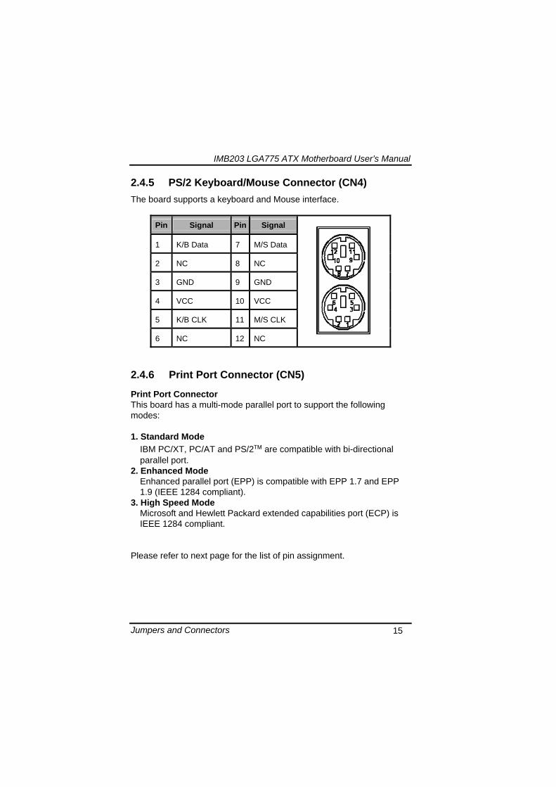
IMB203 LGA775 ATX Motherboard Userrsquos Manual
Jumpers and Connectors 15
245 PS2 KeyboardMouse Connector (CN4) The board supports a keyboard and Mouse interface
Pin Signal Pin Signal
1 KB Data 7 MS Data
2 NC 8 NC
3 GND 9 GND
4 VCC 10 VCC
5 KB CLK 11 MS CLK
6 NC 12 NC
246 Print Port Connector (CN5)
Print Port Connector This board has a multi-mode parallel port to support the following modes 1 Standard Mode
IBM PCXT PCAT and PS2trade are compatible with bi-directional parallel port
2 Enhanced Mode Enhanced parallel port (EPP) is compatible with EPP 17 and EPP 19 (IEEE 1284 compliant)
3 High Speed Mode Microsoft and Hewlett Packard extended capabilities port (ECP) is IEEE 1284 compliant
Please refer to next page for the list of pin assignment
IMB203 LGA775 ATX Motherboard Userrsquos Manual
Jumpers and Connectors 16
Print Port Pin Assignment (Default)
Pin Signal 1 Data Carrier Detect (DCD) 2 Data Set Ready (DSR)
3 Receive Data (RXD)
4 Request to Send (RTS) 5 Transmit Data (TXD)
6 Clear to Send (CTS)
7 Data Terminal Ready (DTR) 8 Ring Indicator (RI)
9 Ground (GND)
247 USB Port Connector (CN6 CN7) The Universal Serial Bus (USB) port connector on the board is for the installation of peripherals supporting the USB interface The CN6CN7 consists of two 4-pin standard USB ports
Pin Signal
1 5 USB Vcc
2 6 USB -
3 7 USB +
4 8 USB GND
IMB203 LGA775 ATX Motherboard Userrsquos Manual
Jumpers and Connectors 17
248 USB Connectors (CN27 CN29 CN33 CN45) The 10-pin standard Universal Serial Bus (USB) connectors CN27293345 on this board are for installing versatile USB interface peripherals
Pin Signal Pin Signal 1 USB 2 USB
3 USB2- 4 USB3-
5 USB2+ 6 USB3+
7 GND 8 GND
9 GND 10 GND
CN45
Pin Signal Pin Signal 1 USB 2 USB
3 USB4- 4 USB5-
5 USB4+ 6 USB5+
7 GND 8 GND
10 GND
CN27 CN29 CN33
249 ATX 4 Pin 12V In Connector (CN14) You can connect it to the ATX12V power supply for CPU Core Voltage
Pin Signal 1 GND 2 GND 3 +12V 4 +12V
IMB203 LGA775 ATX Motherboard Userrsquos Manual
Jumpers and Connectors 18
2410 Digital IO Port (DIO) Connector (CN26) The board is equipped an 8-channel digital IO connector CN26 that meets requirements for a system customary automation control The digital IO can be configured to control cash drawers sense warning signals from an Uninterrupted Power System (UPS) or perform store security control The digital IO is controlled via software programming
Pin Signal Pin Signal
1 DO1 2 DI1
3 DO2 4 DI2
5 DO3 6 DI3
7 DO4 8 DI4
9 GND 10 GND
2411 CPU Fan Connector (CN31) A CPU fan is always needed for cooling CPU heat The CPU fan connector provides power to the CPU fan
Pin Signal 1 Ground 2 +12V 3 Rotation Detection4 Speed Control
2412 SATA Connectors (CN36 CN37 CN41 CN42
CN46 CN47) These SATA connectors are for high-speed SATA interface ports and they can be connected to hard disk devices
Pin Signal
1 GND
2 SATA_TX+
3 SATA_TX-
CN364146
IMB203 LGA775 ATX Motherboard Userrsquos Manual
Jumpers and Connectors 19
4 GND
5 SATA_RX-
6 SATA_RX+
7 GND
IMB203 LGA775 ATX Motherboard Userrsquos Manual
Jumpers and Connectors 20
2413 ATX Power Connector (CN50) Steady and sufficient power can be supplied to all components on the board by connecting the power connector Please make sure all components and devices are properly installed before connecting the power connector If you use a 24-pin ATX power supply please remove the small cover from the power connector before plugging in the power cord otherwise please do not remove it Pin Signal Pin Signal 1 33V 2 33V
3 GND 4 5V
5 GND 6 5V
7 GND 8 PWR
9 5VSB 10 12V
11 12V 12 33V
13 33V 14 -12V
15 GND 16 PS_ON
17 GND 18 GND
19 GND 20 -5V
21 5V 22 5V
23 5V 24 GND
IMB203 LGA775 ATX Motherboard Userrsquos Manual
Jumpers and Connectors 21
2414 Front Panel Connector (CN52)
Power LED
This 3-pin connector denoted as Pin 1 and Pin 5 connects the system power LED indicator to such a switch on the case Pin 1 is assigned as + and Pin 5 as - The Power LED lights up when the system is powered ON Pin 3 is defined as GND
External Speaker and Internal Buzzer Connector
Pin 2 4 6 and 8 can be connected to the case-mounted speaker unit or internal buzzer While connecting the CPU card to an internal buzzer please short pins 2-4 while connecting to an external speaker you need to set pins 2-4 to Open and connect the speaker cable to pin 8 (+) and pin 2 (-)
ATX Power OnOff Button
This 2-pin connector denoted as Pin 9 and 10 connects the front panelrsquos ATX power button to the CPU card which allows users to control ATX power supply to be power onoff
System Reset Switch
Pin 11 and 12 can be connected to the case-mounted reset switch that reboots your computer instead of turning OFF the power switch It is a better way to reboot your system for a longer life of the systemrsquos power supply
HDD Activity LED
This connection is linked to hard drive activity LED on the control panel LED flashes when HDD is being accessed Pin 13 and 14 connect the hard disk drive to the front panel HDD LED Pin 13 assigned as - and Pin 14 as +
IMB203 LGA775 ATX Motherboard Userrsquos Manual
Jumpers and Connectors 22
MEMO
IMB203 LGA775 ATX Motherboard Userrsquos Manual
Hardware Installation 23
CHAPTER 3 HARDWARE INSTALLATION
Before installing the processor please access Intelreg website for more detailed information httpwwwintelcom
31 Installing the Processor The LGA775 processor socket comes with a cover to protect the processor Please install the processor into the CPU socket step by step as below
Hold the hook (A) of the lever and push it down Pull the lever (B) aside to unlock the cover
IMB203 LGA775 ATX Motherboard Userrsquos Manual
Hardware Installation 24
Remove the plastic cap (E) from the cover
Open the cover (C) you can see the contact
Be careful not to touch the contact (D)
IMB203 LGA775 ATX Motherboard Userrsquos Manual
Hardware Installation 25
Place the CPU down into the socket Be careful not to touch the contact
Hold the edges of the CPU and orientate it as the marked direction (G) down into the socket to match the (H) and (F) locations
IMB203 LGA775 ATX Motherboard Userrsquos Manual
Hardware Installation 26
Slightly push down the cover and hook the lever (I~J) The CPU is completely locked
Orientate the CPU cooling fan to fixing holes on the board
IMB203 LGA775 ATX Motherboard Userrsquos Manual
Hardware Installation 27
Screw the CPU cooling fan onto the board
Make sure the CPU fan is plugged to the CPU fan connector
IMB203 LGA775 ATX Motherboard Userrsquos Manual
Hardware Installation 28
32 Installing the Memory The board supports four 240-pin DDR3 DIMM memory sockets with maximum memory capacity up to 16GB Please follow steps below to install the memory modules 1 Push down latches on each side of the DIMM socket 2 Align the memory module with the socket that notches of
memory module must match the socket keys for a correct installation
3 Install the memory module into the socket and push it firmly down until it is fully seated The socket latches are levered upwards and clipped on to the edges of the DIMM
4 Install any remaining DIMM modules
IMB203 LGA775 ATX Motherboard Userrsquos Manual
Hardware Description 29
CHAPTER 4 HARDWARE DESCRIPTION
41 Microprocessors The IMB203 Series supports Intelreg Coretrade 2 Quad Coretrade 2 Duo processors which make your system operated under Windowsreg XP and Linux environments The system performance depends on the microprocessor Make sure all correct settings are arranged for your installed microprocessor to prevent the CPU from damages
42 BIOS The IMB203 Series uses AMI Plug and Play BIOS with a single 32Mbit SPI Flash
43 System Memory The IMB203 Series supports four 240-pin DDR3 DIMM sockets for a maximum memory of 16GB DDR3 SDRAMs The memory module can come in sizes of 1GB 2GB and 4GB
IMB203 LGA775 ATX Motherboard Userrsquos Manual
Hardware Description 30
44 IO Port Address Map The Intelreg Coretrade 2 Extreme Intelreg Coretrade 2 Quad Coretrade 2 Duo CPUs can communicate via IO ports There are total 1KB port addresses available for assignment to other devices via IO expansion cards
Address Devices 000-01F DMA controller 1
020-02D 024-025 028-029 02C-02D Interrupt controller 1
02E-02F Forwarded to LPC(LPC Super IO ) 030-031 034-035 038-039 03C-03D
Interrupt controller 2
040-043 050-053 TimerCounter (8254) 060 Forwarded to LPC (Microcontroller) 061 NMI
062-066 Forwarded to LPC (Microcontroller) 070-077 Real time clock NMI 080-091 DMA page register
092 Processor IF(Reset Generator) 093-09F DMA page register 0A0-0BF Interrupt controller 2 0C0-0DF DMA controller 2
0F0 Processor IF 0F8-0FF Math processor 170-177 Forward to SATA (SATA Controller) 1F0-1F7 Forward to SATA (SATA Controller)
376 Forward to SATA(SATA Controller) 378-37F Parallel Port (LPT) 380-38F SDLC 2 3A0-3AF SDLC 1 3B0-3BF MDA video card
(to be continued)
IMB203 LGA775 ATX Motherboard Userrsquos Manual
Hardware Description 31
Address Devices 3C0-3CF EGA card 3D0-3DF CGA card
3F6 Forward to SATA(SATA Controller) 3F8-3FF Serial port 1 (COM1) 2F8-2FF Serial port 2 (COM2)
45 Interrupt Controller (IRQ) Map The IMB203 Series is a 100 PC compatible control board It consists of 16 interrupt request lines and four out of them can be programmable The mapping list of the 16 interrupt request lines is shown as the following table
IRQ Parity check error IRQ0 System Timer Output
IRQ1 Keyboard
IRQ2 Interrupt rerouting from IRQ8 through IRQ15
IRQ3 Serial port 2
IRQ4 Serial port 1
IRQ5 PCI Device Share
IRQ7 Parallel port
IRQ8 Real time clock
IRQ9 ACPI Controller
IRQ10 PCI Device Share
IRQ11 PCI Device Share
IRQ12 PS2 Mouse
IRQ13 Math coprocessor
IRQ14 SATA Primary (Legacy Mode)
IRQ15 SATA Secondary (Legacy Mode)
IMB203 LGA775 ATX Motherboard Userrsquos Manual
Hardware Description 32
MEMO
IMB203 LGA775 ATX Motherboard Userrsquos Manual
AMI BIOS Setup Utility 33
CHAPTER 5 AMI BIOS SETUP UTILITY
This chapter provides users with detailed description how to set up basic system configuration through the AMIBIOS8 BIOS setup utility 51 Starting To enter the setup screens follow the steps below 1 Turn on the computer and press the ltDelgt key immediately 2 After you press the ltDeletegt key the main BIOS setup menu
displays You can access the other setup screens from the main BIOS setup menu such as the Chipset and Power menus
52 Navigation Keys The BIOS setuputility uses a key-based navigation system called hot keys Most of the BIOS setup utility hot keys can be used at any time during the setup navigation process These keys include ltF1gt ltF10gt ltEntergt ltESCgt ltArrowgt keys and so on
Note Some of navigation keys differ from one screen to another
IMB203 LGA775 ATX Motherboard Userrsquos Manual
AMI BIOS Setup Utility 34
LeftRight The Left ltArrowgt keys allow you to select a setup screen
UpDown The Up and Down ltArrowgt keys allow you to select a setup screen or sub-screen
+minus PlusMinus The Plus and Minus ltArrowgt keys allow you to change the field value of a particular setup item
Tab The ltTabgt key allows you to select setup fields
F1 The ltF1gt key allows you to display the General Help screen
F10 The ltF10gt key allows you to save any changes you have made and exit Setup Press the ltF10gt key to save your changes
Esc
The ltEscgt key allows you to discard any changes you have made and exit the Setup Press the ltEscgt key to exit the setup without saving your changes
Enter
The ltEntergt key allows you to display or change the setup option listed for a particular setup item The ltEntergt key can also allow you to display the setup sub- screens
IMB203 LGA775 ATX Motherboard Userrsquos Manual
AMI BIOS Setup Utility 35
53 Main Menu When you first enter the Setup Utility you will enter the Main setup screen You can always return to the Main setup screen by selecting the Main tab There are two Main Setup options They are described in this section The Main BIOS Setup screen is shown below
System TimeDate
Use this option to change the system time and date Highlight System Time or System Date using the ltArrowgt keys Enter new values through the keyboard Press the ltTabgt key or the ltArrowgt keys to move between fields The date must be entered in MMDDYY format The time is entered in HHMMSS format
IMB203 LGA775 ATX Motherboard Userrsquos Manual
AMI BIOS Setup Utility 36
54 Advanced Menu The Advanced menu allows users to set configuration of the CPU and other system devices You can select any of the items in the left frame of the screen to go to the sub menus
CPU Configuration IDE Configuration SuperIO Configuration Hardware Health Configuration ACPI Configuration AHCI Configuration Intel iAMT Configuration Intel VT-d Configuration MPS Configuration PCI Express Configuration Trusted Computing USB Configuration
For items marked with ldquo rdquo please press ltEntergt for more options
IMB203 LGA775 ATX Motherboard Userrsquos Manual
AMI BIOS Setup Utility 37
CPU Configuration This screen shows the CPU Configuration and you can change the value of the selected option
Max CPUID Value Limit
You can enable this item to let legacy operating systems boot even without support for CPUs with extended CPU ID functions
Execute-Disable Bit Capability This item helps you enable or disable the No-Execution Page Protection Technology
Core Multi-Processing This feature controls the functionality of the Core Multi-Processing to allow the processor to execute multitasking function
PECI Use this item PECI (Platform Environment Control Interface) to execute the processor temperature monitoring and management
IMB203 LGA775 ATX Motherboard Userrsquos Manual
AMI BIOS Setup Utility 38
Intel (R) C-STATE tech Use this item to enable or disable the C-State technology
IDE Configuration You can use this screen to select options for the IDE Configuration and change the value of the selected option A description of the selected item appears on the right side of the screen For items marked with ldquo rdquo please press ltEntergt for more options
SATA1 Configuration
Use this item to control the onboard SATA controller Here are the options for your selection Compatible Disabled and Enhanced
Configure SATA1 as Use this item to choose the SATA operation mode Here are the options for your selection IDE and AHCI
SATA2 Configuration Use this item to control the onboard SATA controller Here are the options for your selection Enhanced and Disabled
IMB203 LGA775 ATX Motherboard Userrsquos Manual
AMI BIOS Setup Utility 39
PrimarySecondaryThird IDE Master Select one of the hard disk drives to configure IDE devices installed in the system by pressing ltEntergt for more options
Fifth IDE Master Select one of the hard disk drives to configure IDE devices installed in the system by pressing ltEntergt for more options
IMB203 LGA775 ATX Motherboard Userrsquos Manual
AMI BIOS Setup Utility 40
SuperIO Configuration You can use this screen to select options for the SuperIO Configuration and change the value of the selected option A description of the selected item appears on the right side of the screen
Serial Port1 Address
This option specifies the base IO port address and Interrupt Request address of serial port 1 The Optimal setting is 3F8IRQ4 The Fail-Safe default setting is Disabled
Serial Port2 Address This option specifies the base IO port address and Interrupt Request address of serial port 2 The Optimal setting is 2F8IRQ3 The Fail-Safe setting is Disabled
Parallel Port Address This item allows you to determine the IO address for onboard parallel port There are several options for your selection
Parallel Port Mode
IMB203 LGA775 ATX Motherboard Userrsquos Manual
AMI BIOS Setup Utility 41
Select an operating mode for the onboard parallel (printer) port
Parallel Port IRQ Use this item to set up the IRQ for onboard parallel port
Serial Port3 Address This item specifies the base IO port address and Interrupt Request address of serial port 3 The Optimal setting is 3E8IRQ11 The Fail-Safe default setting is Disabled
Serial Port3 IRQ This item specifies the IRQ used by the serial port 3
Serial Port4 Address This item specifies the base IO port address and Interrupt Request address of serial port 4 The Optimal setting is 2E8IRQ10 The Fail-Safe default setting is Disabled
Serial Port4 IRQ This item specifies the IRQ used by the serial port 4
IMB203 LGA775 ATX Motherboard Userrsquos Manual
AMI BIOS Setup Utility 42
Hardware Health Configuration This screen shows the Hardware Health Configuration and a description of the selected item appears on the right side of the screen
HW Health Configuration
This screen displays the temperature of CPU and System Fan Speed Vcore etc
IMB203 LGA775 ATX Motherboard Userrsquos Manual
AMI BIOS Setup Utility 43
ACPI Configuration You can use this screen to select options for the ACPI Configuration and change the value of the selected option A description of the selected item appears on the right side of the screen
General ACPI Configuration
Scroll to this item and press ltEntergt to view the General ACPI Configuration sub menu which contains General ACPI (Advanced Configuration and Power Management Interface) options for your configuration
Advanced ACPI Configuration Scroll to this item and press ltEntergt to view the Advanced ACPI Configuration sub menu which contains Advanced ACPI (Advanced Configuration and Power Management Interface) options for your configuration
Chipset ACPI Configuration Scroll to this item and press ltEntergt to view the Chipset ACPI Configuration sub menu which contains Chipset ACPI (Advanced Configuration and Power Management
IMB203 LGA775 ATX Motherboard Userrsquos Manual
AMI BIOS Setup Utility 44
Interface) options for your configuration AHCI Configuration
You can use this screen to select options for the AHCI Configuration and change the value of the selected option A description of the selected item appears on the right side of the screen
AHCI BIOS Support You can enable or disable this item to control the AHCI function of the SATA controller
IMB203 LGA775 ATX Motherboard Userrsquos Manual
AMI BIOS Setup Utility 45
Intel iAMT Configuration You can use this screen to select options for the Intel iAMT Configuration and change the value of the selected option A description of the selected item appears on the right side of the screen
Intel iAMT Support
You can enable this item to support iAMT (active management technology) function to follow up the procedure for the access to AMI program screen
Unconfigure iAMTME Use this item to unconfigure the iAMTME settings
IMB203 LGA775 ATX Motherboard Userrsquos Manual
AMI BIOS Setup Utility 46
Intel VT-d Configuration You can use this screen to select options for the Intel VT-d Configuration and change the value of the selected option A description of the selected item appears on the right side of the screen
Intel VT-d Virtualization Technology for Directed IO (VT-d) extends Virtualization Technology (VT) roadmap by providing hardware assists for virtualization solution VT-d can help end users improve security and reliability of the systems and also improve performance of IO devices in virtualized environment Here are the options for your selection Disabled and Enabled
IMB203 LGA775 ATX Motherboard Userrsquos Manual
AMI BIOS Setup Utility 47
Remote Access Configuration You can use this screen to select options for the Remote Access Configuration and change the value of the selected option A description of the selected item appears on the right side of the screen
Remote Access Use this item to enable or disable the Remote Access function
IMB203 LGA775 ATX Motherboard Userrsquos Manual
AMI BIOS Setup Utility 48
PCI Express Configuration This screen shows the PCI Express Configuration and you can change its value A description of the selected item appears on the right side of the screen
Active State Power-Management
Use this item to enable or disable the function of Active State Power-Management to provide you with lower power consumption The default setting is Disabled
IMB203 LGA775 ATX Motherboard Userrsquos Manual
AMI BIOS Setup Utility 49
Trusted Computing You can use this screen to select options for the Trusted Computing and change the value of the selected option A description of the selected item appears on the right side of the screen
TCGTPM SUPPORT Use this item to control the Trusted Platform Module (TPM) function
IMB203 LGA775 ATX Motherboard Userrsquos Manual
AMI BIOS Setup Utility 50
USB Configuration You can use this screen to select options for the USB Configuration and change the value of the selected option A description of the selected item appears on the right side of the screen
USB Functions
This item allows you to enable or disable USB functions
Legacy USB Support Use this item to enable or disable support for USB device on legacy operating system The default setting is Enabled
USB 20 Controller Mode Use this item to configure the USB 20 controller The default setting is HiSpeed
BIOS EHCI Hand-Off Enabling this item provide the support for operating systems without an EHCI hand-off feature The default setting is Enabled
IMB203 LGA775 ATX Motherboard Userrsquos Manual
AMI BIOS Setup Utility 51
IMB203 LGA775 ATX Motherboard Userrsquos Manual
AMI BIOS Setup Utility 52
55 PCI PnP Menu The PCI PnP menu allows users to change the advanced settings for PCIPnP devices
Clear NVRAM
Use this item to clear the data in the NVRAM (CMOS) Here are the options for your selection No and Yes
Plug amp Play OS When the setting is No Use this item to configure all the devices in the system When the setting is Yes and if you install a Plug and Play operating system the operating system configures the Plug and Play devices not required for boot The default setting is No
IMB203 LGA775 ATX Motherboard Userrsquos Manual
AMI BIOS Setup Utility 53
PCI Latency Timer This item controls how long a PCI device can hold the PCI bus before another takes over The longer the latency the longer the PCI device can retain control of the bus before handing it over to another PCI device There are several options for your selection
Allocate IRQ to PCI VGA This item allows BIOS to choose an IRQ to assign for the PCI VGA card Here are the options for your selection No and Yes
Palette Snooping Some old graphic controllers need to ldquosnooprdquo on the VGA palette and then map it to their display as a way to provide boot information and VGA compatibility This item allows such snooping to take place Here are the options for your selection Disabled and Enabled
PCI IDE BusMaster This item is a toggle for the built-in driver that allows the onboard IDE controller to perform DMA (Direct Memory Access) transfer Here are the options for your selection Disabled and Enabled
OffBoard PCIISA IDE Card This item is for any other non-onboard PCIISA IDE controller adapter There are several options for your selection
IRQ3457910111415 These items will allow you to assign each system interrupt a type depending on the type of device using the interrupt The option ldquoAvailablerdquo means the IRQ is going to assign automatically Here are the options for your selection Available and Reserved
DMA Channel 013567 These items will allow you to assign each DMA channel a type depending on the type of device using the channel The option ldquoAvailablerdquo means the channel is going to assign automatically Here are the options for your selection Available and Reserved
IMB203 LGA775 ATX Motherboard Userrsquos Manual
AMI BIOS Setup Utility 54
56 Boot Menu The Boot menu allows users to change boot options of the system You can select any of the items in the left frame of the screen to go to the sub menus
Boot Settings Configuration Boot Device Priority Removable Drives
For items marked with ldquo rdquo please press ltEntergt for more options
IMB203 LGA775 ATX Motherboard Userrsquos Manual
AMI BIOS Setup Utility 55
Boot Settings Configuration
Quick Boot
Enabling this item lets the BIOS skip some power on self tests (POST) The default setting is Enabled
AddOn ROM Display Mode This item selects the display mode for option ROM The default setting is Force BIOS
Boot Num-Lock Use this item to select the power-on state for the NumLock The default setting is On
PS2 Mouse Support This item determines if the BIOS should reserve IRQ12 for the PS2 mouse or allow other devices to make use of this IRQ Here are the options for your selection Auto Enabled and Disabled
Wait For lsquoF1rsquo Of Error If this item is enabled the system waits for the F1 key to be pressed when error occurs The default setting is Enabled
Hit lsquoDELrsquo Message Display If this item is enabled the system displays the message
IMB203 LGA775 ATX Motherboard Userrsquos Manual
AMI BIOS Setup Utility 56
ldquoPress DEL to run Setuprdquo during POST The default setting is Enabled
Interrupt 19 Capture If this item is enabled this function makes the option ROMs to trap Interrupt 19 The default setting is Disabled
Boot Device Priority The Boot Device Priority screen specifies the boot device priority sequence from the available devices
IMB203 LGA775 ATX Motherboard Userrsquos Manual
AMI BIOS Setup Utility 57
Removable Drives Use this screen to view the removable drives in the system The BIOS will attempt to arrange the removable drive boot sequence automatically You can also change the booting sequence
IMB203 LGA775 ATX Motherboard Userrsquos Manual
AMI BIOS Setup Utility 58
57 Security Menu The Security menu allows users to change the security settings for the system
Supervisor Password
This item indicates whether a supervisor password has been set If the password has been installed Installed displays If not Not Installed displays
User Password This item indicates whether a user password has been set If the password has been installed Installed displays If not Not Installed displays
Change Supervisor Password Select this option and press ltEntergt to access the sub menu You can use the sub menu to change the supervisor password
Change User Password Select this option and press ltEntergt to access the sub menu You can use the sub menu to change the user password
IMB203 LGA775 ATX Motherboard Userrsquos Manual
AMI BIOS Setup Utility 59
58 Chipset Menu The Chipset menu allows users to change the advanced chipset settings You can select any of the items in the left frame of the screen to go to the sub menus
North Bridge Configuration South Bridge Configuration ME Subsystem Configuration
For items marked with ldquo rdquo please press ltEntergt for more options
IMB203 LGA775 ATX Motherboard Userrsquos Manual
AMI BIOS Setup Utility 60
North Bridge Configuration
Memory Remap Feature
Use this item to enable or disable the remapping of the overlapped PCI memory above the total physical memory Only 64-bit OS supports this function
DRAM Frequency This item allows you to control the Memory Clock
Configure DRAM Timing by SPD This item can enable or disable DRAM timing by SPD (Serial Presence Detect) device which is a small EEPROM chip on the memory module containing important information about the module speed size addressing mode and various parameters
Memory Hole You can reserve this area of system memory for ISA adapter ROM When this area is reserved it cannot be cached Check the user information of peripherals that need to use this area o f system memory for the memory requirements Here are the options Disabled and 15M-16M
IMB203 LGA775 ATX Motherboard Userrsquos Manual
AMI BIOS Setup Utility 61
Initiate Graphic Adapter When using multiple graphics cards this item can select which graphics controller to be the primary display device during boot
IGD Graphics Mode Select This item allows you to select the amount of system memory used by the internal graphics device
PEG Port ConfigurationPEG Port This item is a toggle to enable or disable the PCI Express port Here are the options for your selection Auto and Disabled
Video Function Configuration Press ltEntergt for the sub-menu for setting up video function
IMB203 LGA775 ATX Motherboard Userrsquos Manual
AMI BIOS Setup Utility 62
South Bridge Configuration
GbE Wake Up From S5 This item specifies whether the system will be awakened from the S5 power
HDA Controller This item allows you to enable or disable the HD audio support
Restore on AC Power Loss This item can control how the PC will behave once power is restored following a power outage or other unexpected shutdown
PCIE Port Configuration This item allows you to set or disable the PCI Express Ports
IMB203 LGA775 ATX Motherboard Userrsquos Manual
AMI BIOS Setup Utility 63
ME Subsystem Configuration
It is strongly recommended that you do not modify these options unless you are an advanced user
IMB203 LGA775 ATX Motherboard Userrsquos Manual
AMI BIOS Setup Utility 64
59 Exit Menu The Exit menu allows users to load your system configuration with optimal or failsafe default values
Save Changes and Exit
When you have completed the system configuration changes select this option to leave Setup and reboot the computer so the new system configuration parameters can take effect Select Save Changes and Exit from the Exit menu and press ltEntergt Select Ok to save changes and exit
Discard Changes and Exit Select this option to quit Setup without making any permanent changes to the system configuration Select Discard Changes and Exit from the Exit menu and press ltEntergt Select Ok to discard changes and exit
Load Optimal Defaults It automatically sets all Setup options to a complete set of default settings when you select this option The Optimal settings are designed for maximum system performance but may not work best for all computer applications In particular do not use the Optimal Setup options if your
IMB203 LGA775 ATX Motherboard Userrsquos Manual
AMI BIOS Setup Utility 65
computer is experiencing system configuration problems Select Load Optimal Defaults from the Exit menu and press ltEntergt
Load Fail-Safe Defaults It automatically sets all Setup options to a complete set of default settings when you select this option The Fail-Safe settings are designed for maximum system stability but not maximum performance Select the Fail-Safe Setup options if your computer is experiencing system configuration problems Select Load Fail-Safe Defaults from the Exit menu and press ltEntergt Select Ok to load Fail-Safe defaults
IMB203 LGA775 ATX Motherboard Userrsquos Manual
AMI BIOS Setup Utility 66
MEMO
IMB203 LGA775 ATX Motherboard Userrsquos Manual
Installation of Drivers 67
CHPATER 6 INSTALLATION OF DRIVERS
The device drivers are located on the Product Information CD-ROM that comes with the IMB203 Series package The auto-run function of drivers will guide you to install the utilities and device drivers under a Windows system You can follow the onscreen instructions to install these devices
Chipse VGA LAN Audio iAMT MEI
61 Installing Chipset Driver 1 Run the SETUPEXE program from the driver directory in
your driver CD Click ldquoNextrdquo to next step
IMB203 LGA775 ATX Motherboard Userrsquos Manual
Installation of Drivers 68
2 An Intelreg License Agreement appears to show you the important information Click ldquoYesrdquo to next step
3 Refer to the Readme file below to view the system requirements and installation information
IMB203 LGA775 ATX Motherboard Userrsquos Manual
Installation of Drivers 69
3-1 Please wait while running the following setup operations
3-2 Please wait while running the following setup operations
IMB203 LGA775 ATX Motherboard Userrsquos Manual
Installation of Drivers 70
4 Click ldquoFinishrdquo to complete the setup process
5 You will be asked to reboot your computer when the installation is completed Please click ldquoYes I want to restart my computer nowrdquo if you donrsquot need to install any other drivers Otherwise please click ldquoNo I will restart my computer laterrdquo and go on next step
IMB203 LGA775 ATX Motherboard Userrsquos Manual
Installation of Drivers 71
62 Installing VGA Driver 1 Run the SETUPEXE program from the driver directory in
your driver CD Click ldquoNextrdquo to next step
2 An Intelreg License Agreement appears to show you the
important information Click ldquoYesrdquo to next step
IMB203 LGA775 ATX Motherboard Userrsquos Manual
Installation of Drivers 72
3 The message of Readme File Information appears to show you the system requirements and installation information Please click ldquoNextrdquo
4 Please wait while running the following setup operations
When this message appears please click ldquoNextrdquo
IMB203 LGA775 ATX Motherboard Userrsquos Manual
Installation of Drivers 73
5 Click ldquoFinishrdquo to complete the setup process
6 You will be asked to reboot your computer when the installation is completed Please click ldquoYes I want to restart my computer nowrdquo if you donrsquot need to install any other drivers Otherwise please click ldquoNo I will restart my computer laterrdquo and click ldquoFinishrdquo to complete the installation
IMB203 LGA775 ATX Motherboard Userrsquos Manual
Installation of Drivers 74
63 Installing LAN Driver
11 Run the InstallShield Wizard for Network Connections from
the driver directory in your driver CD Click ldquoNextrdquo to next step
IMB203 LGA775 ATX Motherboard Userrsquos Manual
Installation of Drivers 75
12 An Intelreg License Agreement appears to show you the important information Click ldquoYesrdquo to next step
13 A Setup Options window appears that you can select the
program features you want to install
IMB203 LGA775 ATX Motherboard Userrsquos Manual
Installation of Drivers 76
2 Click ldquoInstallrdquo to start the installation
3 Please wait while running the following installation operation
IMB203 LGA775 ATX Motherboard Userrsquos Manual
Installation of Drivers 77
4 Click ldquoFinishrdquo to complete the installation
Note The Driver item [Wake on Directed Packet] default is Enabled under Windows Vista
格式化 字型 (符號) Arial
格式化 字型 (符號) Arial
格式化 字型 斜體 字型色彩 黑色 (符號) Arial 非加寬 緊縮
格式化 字型 斜體 字型色彩 黑色 (符號) Arial 非加寬 緊縮
格式化 字型 (符號) Arial 非加寬 緊縮
IMB203 LGA775 ATX Motherboard Userrsquos Manual
Installation of Drivers 78
64 Installing AUDIO Driver 1 Run the InstallShield Wizard for Realtek High Definition
Audio Driver from the driver directory in your driver CD Click ldquoNextrdquo to next step
IMB203 LGA775 ATX Motherboard Userrsquos Manual
Installation of Drivers 79
2 Click ldquoInstallrdquo to start the installation and wait while running the installation operation
3 Click ldquoFinishrdquo to complete the installation
IMB203 LGA775 ATX Motherboard Userrsquos Manual
Installation of Drivers 80
65 Installing iAMT (Active Management Technology) Driver
Note You must download and properly install the required NET version 35 provided from a separate downloading of the actual FimwareTools kit releases posted on VIP prior to loading the MEILMS Driver stack
651 LMS_SOL Setup
1 Run the setup program to install Intelreg Active Management Technology onto your computer It is strongly recommended that you exit all programs before continuing Click ldquoNextrdquo to next step
格式化 字型 (符號) Arial
格式化 字型 (符號) Arial 非加寬 緊縮
IMB203 LGA775 ATX Motherboard Userrsquos Manual
Installation of Drivers 81
2 An Intelreg license agreement appears that you need to continue the setup program by clicking ldquoYesrdquo to accept the terms
IMB203 LGA775 ATX Motherboard Userrsquos Manual
Installation of Drivers 82
3 Refer to the Readme file below to view the system requirements and installation information Click ldquoNextrdquo to next setup
4 Please wait while running the following installation operation
IMB203 LGA775 ATX Motherboard Userrsquos Manual
Installation of Drivers 83
5 Click ldquoFinishrdquo to complete the installation
IMB203 LGA775 ATX Motherboard Userrsquos Manual
Installation of Drivers 84
652 LMS_SOL_IS Setup
1 Run the setup program to install Intelreg Active Management Technology onto your computer It is strongly recommended that you exit all programs before continuing Click ldquoNextrdquo to next step
IMB203 LGA775 ATX Motherboard Userrsquos Manual
Installation of Drivers 85
2 An Intelreg license agreement appears that you need to continue the setup program by clicking ldquoYesrdquo to accept the terms
IMB203 LGA775 ATX Motherboard Userrsquos Manual
Installation of Drivers 86
3 Refer to the Readme file below to view the system requirements and installation information Click ldquoNextrdquo to next setup
4 Please wait while running the following installation operation
IMB203 LGA775 ATX Motherboard Userrsquos Manual
Installation of Drivers 87
5 Click ldquoFinishrdquo to complete the installation
IMB203 LGA775 ATX Motherboard Userrsquos Manual
Installation of Drivers 88
66 Installing MEI (Management Engine Interface) Driver
Note You must download and properly install the required NET version 35 provided from a separate downloading of the actual FimwareTools kit releases posted on VIP prior to loading the MEILMS Driver stack
1 Run the setup program to install Intelreg Management Engine
Interface onto your computer It is strongly recommended that you exit all programs before continuing Click ldquoNextrdquo to next step
格式化 字型 (符號) Arial
格式化 字型 (符號) Arial 非加寬 緊縮
IMB203 LGA775 ATX Motherboard Userrsquos Manual
Installation of Drivers 89
2 An Intelreg license agreement appears that you need to continue the setup program by clicking ldquoYesrdquo to accept the terms
IMB203 LGA775 ATX Motherboard Userrsquos Manual
Installation of Drivers 90
3 Refer to the Readme file below to view the system requirements and installation information Click ldquoNextrdquo to next setup
4 Please wait while running the following installation operation
IMB203 LGA775 ATX Motherboard Userrsquos Manual
Installation of Drivers 91
5 Click ldquoFinishrdquo to complete the installation
IMB203 LGA775 ATX Motherboard Userrsquos Manual
Installation of Drivers 92
MEMO
IMB203 LGA775 ATX Motherboard Userrsquos Manual
Watchdog Timer 93
APPENDIX A WATCHDOG TIMER
Watchdog Timer Setting After the system stops working for a while it can be auto-reset by the Watchdog Timer The integrated Watchdog Timer can be set up in the system reset mode by program
Using the Watchdog Function Start darr Un-Lock WDT O 2E 87 Un-lock super IO
O 2E 87 Un-lock super IO darr Set WDT Function O 2E 2D O 2F 20 Select Logic device O 2E 07 O 2F 08 darr Activate WDT O 2E 30
O 2F 01 Set Second or Minute O 2E F5
O 2F N N=00 or 08(See below table) darr Set base timer O 2E F6
O 2F M=000102hellipFF(Hex) Value=0 to 255 darr WDT counting
re-set timer O 2E F6
O 2F M M=000102hellipFF(See below table) darr
格式化
格式化 項目符號及編號
格式化 項目符號及編號
格式化 字型 8 點 字型色彩黑色
格式化 字型 8 點 字型色彩黑色
格式化 定位點 1257 字元左 + 不在 1012 字元 + 1386字元
格式化 字型 8 點 字型色彩黑色
格式化 定位點 1257 字元左 + 不在 134 字元 + 1362字元
格式化 字型色彩 黑色
格式化 字型色彩 黑色
刪除
IMB203 LGA775 ATX Motherboard Userrsquos Manual
Watchdog Timer 94
IF No re-set timer WDT time-out generate RESET IF to disable WDT O 2E 30
O 2F 00 Can be disable at any time
N=00
M= 00h Time-out Disable 01h Time-out occurs after 1 second 02h Time-out occurs after 2 second 03h Time-out occurs after 3 second helliphelliphelliphelliphelliphelliphelliphelliphellip FFh Time-out occurs after 255 second
N=08
M= 00h Time-out Disable 01h Time-out occurs after 1 minute 02h Time-out occurs after 2 minutes 03h Time-out occurs after 3 minutes helliphelliphelliphelliphelliphelliphelliphelliphellip
FFh Time-out occurs after 255 minutes
格式化 字型色彩 黑色
格式化 字型色彩 黑色
IMB203 LGA775 ATX Motherboard Userrsquos Manual
PCI IRQ Routing 95
APPENDIX B PCI IRQ ROUTING
PICMG PCI IRQ Routing
Device ID Slot Int
PCI Slot 0 31 0 BCDA PCI Slot 1 30 1 CDAB PCI Slot 2 29 2 DABC PCI Slot 3 28 3 ABCD
IMB203 LGA775 ATX Motherboard Userrsquos Manual
PCI IRQ Routing 96
MEMO
IMB203 LGA775 ATX Motherboard Userrsquos Manual
Configuring SATA for RAID Function 97
APPENDIX C CONFIGURING SATA FOR RAID
FUNCTION
Configuring SATA Hard Drive(s) for RAID Function (Controller IntelregICH10DODO DH only) Please follow up the steps below to configure SATA hard drive(s) (1) Install SATA hard drive(s) in your system (2) Enter the BIOS Setup to configure SATA controller mode and boot
sequence (3) Configure RAID by the RAID BIOS (4) Install the SATA controller driver during the OS installation Before you begin the SATA configuration please prepare (a) Two SATA hard drives (to ensure optimal performance it is
recommended that you use two hard drives with identical model and capacity) If you do not want to create RAID with the SATA controller you may prepare only one hard drive
(b) An empty formatted floppy disk (c) Windows XP setup disk (1) Installing SATA hard drive(s) in your system
Connect one end of the SATA signal cable to the rear of the SATA hard drive and the other end to available SATA port(s) on the board Then connect the power connector of power supply to the hard drive
(2) Configuring SATA controller mode and boot sequence by the BIOS Setup You have to make sure whether the SATA controller is configured correctly by system BIOS Setup and set up BIOS boot sequence for the SATA hard drive(s)
IMB203 LGA775 ATX Motherboard Userrsquos Manual
Configuring SATA for RAID Function 98
(2)-1-1 Turn on your system and then press the Del button to enter BIOS Setup during running POST (Power-On Self Test) If you want to create RAID just go to the Advanced Settings menuIDE configuration select the Configure SATA1 as and press ltEntergt for more options
IMB203 LGA775 ATX Motherboard Userrsquos Manual
Configuring SATA for RAID Function 99
(2)-1-2 A list of options appears please select RAID
IMB203 LGA775 ATX Motherboard Userrsquos Manual
Configuring SATA for RAID Function 100
(2)-2 Set CDROM for First Boot Device under the Boot Settings menu to boot CD-ROM after system restarts
(2)-3 Save and exit the BIOS Setup
IMB203 LGA775 ATX Motherboard Userrsquos Manual
Configuring SATA for RAID Function 101
(3) Configuring RAID by the RAID BIOS Enter the RAID BIOS setup utility to configure a RAID array Skip this step and proceed to Section 4 if you do not want to create a RAID (3)-1 After the POST memory testing and before the operating
system booting a message Press ltCtrl-Igt to enter Configuration Utility shows up accordingly press ltCTRL+ Igt to enter the RAID BIOS setup utility
(3)-2 After you press ltCTRL+ Igt the Create RAID Volume screen will appear If you want to create a RAID array select the Create RAID Volume option in the Main Menu and press ENTER
IMB203 LGA775 ATX Motherboard Userrsquos Manual
Configuring SATA for RAID Function 102
(3)-3-1 After entering the CREATE VOLUME MENU screen you can type the disk array name with 1~16 letters (letters cannot be special characters) in the item ldquoNamerdquo
(3)-3-2 When finished press ENTER to select a RAID level There are three RAID levels RAID0 RAID1 and RAID5 amp RAID10 Select a RAID level and press ENTER
IMB203 LGA775 ATX Motherboard Userrsquos Manual
Configuring SATA for RAID Function 103
(3)-4 Set the stripe block size The KB is the standard unit of stripe block size The stripe block size can be 4KB to 128KB After the setting press ENTER for the array capacity
(3)-5 After setting all the items on the menu select Create Volume
and press ENTER to start creating the RAID array
IMB203 LGA775 ATX Motherboard Userrsquos Manual
Configuring SATA for RAID Function 104
(3)-6 When prompting the confirmation press ldquoYldquo to create this volume or ldquoNldquo to cancel the creation
After the creation is completed you can see detailed information about the RAID Array in the DISKVOLUME INFORMATION section including RAID mode disk block size disk name and disk capacity etc
IMB203 LGA775 ATX Motherboard Userrsquos Manual
Configuring SATA for RAID Function 105
Delete RAID Volume If you want to delete a RAID volume select the Delete RAID Volume option in Main Menu Press ENTER and follow on-screen instructions
Please press [ESC] to exit the RAID BIOS utility Now you can proceed to install a SATA driver controller and the operating system
IMB203 LGA775 ATX Motherboard Userrsquos Manual
Configuring SATA for RAID Function 106
(4) Making a SATA Driver Disk To install the operating system onto a serial ATA hard disk successfully you need to install the SATA controller driver during the OS installation Without the driver the hard disk may not be recognized during the Windows setup process First of all please format a blank floppy disk Secondly follow up these steps below to produce a SATA driver disk Users can insert the Driver CD and the formatted blank floppy disk in another system And then please copy all of file of the f6flpy32 folder in the Driver CD to a floppy disk Note Please copy all of file of the f6flpy64 folder if installing 64-bit
Windows Operating System
IMB203 LGA775 ATX Motherboard Userrsquos Manual
Configuring SATA for RAID Function 107
(5) Installing the SATA controller driver during the OS installation Now the SATA driver disk is ready and BIOS settings configured you can proceed to install Windows 2000XP onto your SATA hard drive using the SATA driver Here is an example for Windows XP installation (5)-1 Restart your system to boot the Windows 2000XP Setup disk
and press F6 button as soon as you see the message Press F6 if you need to install a 3rd party SCSI or RAID driver After pressing the F6 button there will be a few moments for some files being loaded before next screen appears
IMB203 LGA775 ATX Motherboard Userrsquos Manual
Configuring SATA for RAID Function 108
(5)-2 When you see the screen below insert the floppy disk containing the SATA driver and press ldquoSrdquo
(5)-3 If the Setup correctly recognizes the driver of the floppy disk
a controller menu will appear below Use the ARROW keys to select Intel(R) ICH8RICH9RICH10RDO SATA RAID Controller and press ENTER Then it will begin to load the SATA driver from the floppy disk
IMB203 LGA775 ATX Motherboard Userrsquos Manual
Configuring SATA for RAID Function 109
Note If a message on the screen saying that one or some file(s) cannot be found please check the floppy disk or copy the correct SATA driver again from the driver CD
IMB203 LGA775 ATX Motherboard Userrsquos Manual
Configuring SATA for RAID Function 110
MEMO
IMB203 LGA775 ATX Motherboard Userrsquos Manual
iAMT Settings 111
APPENDIX D iAMT SETTINGS
The Intelreg Active Management Technology (Intelreg iAMT) has decreased a major barrier to IT efficiency that uses built-in platform capabilities and popular third-party management and security applications to allow IT a better discovering healing and protection their networked computing assets In order to utilize Intel iAMT you must enter the ME BIOS (CTRL + P during system startup) change the ME BIOS password and then select ldquoIntelreg iAMTrdquo as the manageability feature
D1 Entering MEBx 1 You must go to BIOS TO start iAMT function 2 Exit from BIOS after starting iAMT and press Ctrl+P to enter MEBx Setting
It is better to press Ctrl+P before the screen popping out
格式化
IMB203 LGA775 ATX Motherboard Userrsquos Manual
iAMT Settings 112
D2 Set amp Change Password 1 You will be asked to set a password when first log in The default
password is lsquoadminrsquo
2 You will be asked to change the password before setting ME
Change Password
IMB203 LGA775 ATX Motherboard Userrsquos Manual
iAMT Settings 113
3 You must confirm your new password while revising (as Remark 1)
Remark 1 The new password must contain (example 11qqQQ) (default value)
Eight characters
One upper case
One lower case
One number
One special symbol such as $ or
( excepted)
Underline ( _ ) and space are valid characters for password but they wonrsquot make higher complexity
IMB203 LGA775 ATX Motherboard Userrsquos Manual
iAMT Settings 114
D3 Intelreg iAMT Settings 1 Select Intelreg iAMT Configuration and press ltENTERgt
2 Key in the Host Name If Intelreg iAMT set to lsquoDHCPlsquo the Host name must be identical to the operating system mechanic
IMB203 LGA775 ATX Motherboard Userrsquos Manual
iAMT Settings 115
3 Select TCPIP to get into Network interface and set it to lsquoENABLEDrsquo into DHCP Mode and set it to lsquoDISABLEDrsquo (as Remark 2) into Domain name and set the Intel Management Engine domain name such as lsquoAMTintelcomrsquo
(3-1)
(3-2)
IMB203 LGA775 ATX Motherboard Userrsquos Manual
iAMT Settings 116
Remark 2 DHCP Mode lsquoDISABLEDlsquo if DHCP Mode is disabled you can make the following settings
IP address
Subnet mask
IMB203 LGA775 ATX Motherboard Userrsquos Manual
iAMT Settings 117
Default Gateway address
Preferred DNS address
IMB203 LGA775 ATX Motherboard Userrsquos Manual
iAMT Settings 118
Alternate DNS address
Domain name
4 Exit from MEBx after completing the iAMT settings
IMB203 LGA775 ATX Motherboard Userrsquos Manual
iAMT Settings 119
D4 iAMT Web Console 1 From a web browser please type http(IP ADDRESS)16992
which connects to iAMT Web Example http1014021416992
2 To log on you will be required to type in username and password
for access to the Web
USER admin (default value)
PASS (MEBx password)
IMB203 LGA775 ATX Motherboard Userrsquos Manual
iAMT Settings 120
3 Enter the iAMT Web
4 Click Remote Control and select commands on the right side
IMB203 LGA775 ATX Motherboard Userrsquos Manual
iAMT Settings 121
5 When you have finished using the iAMT Web console close the Web browser
IMB203 LGA775 ATX Motherboard Userrsquos Manual
iAMT Settings 122
MEMO
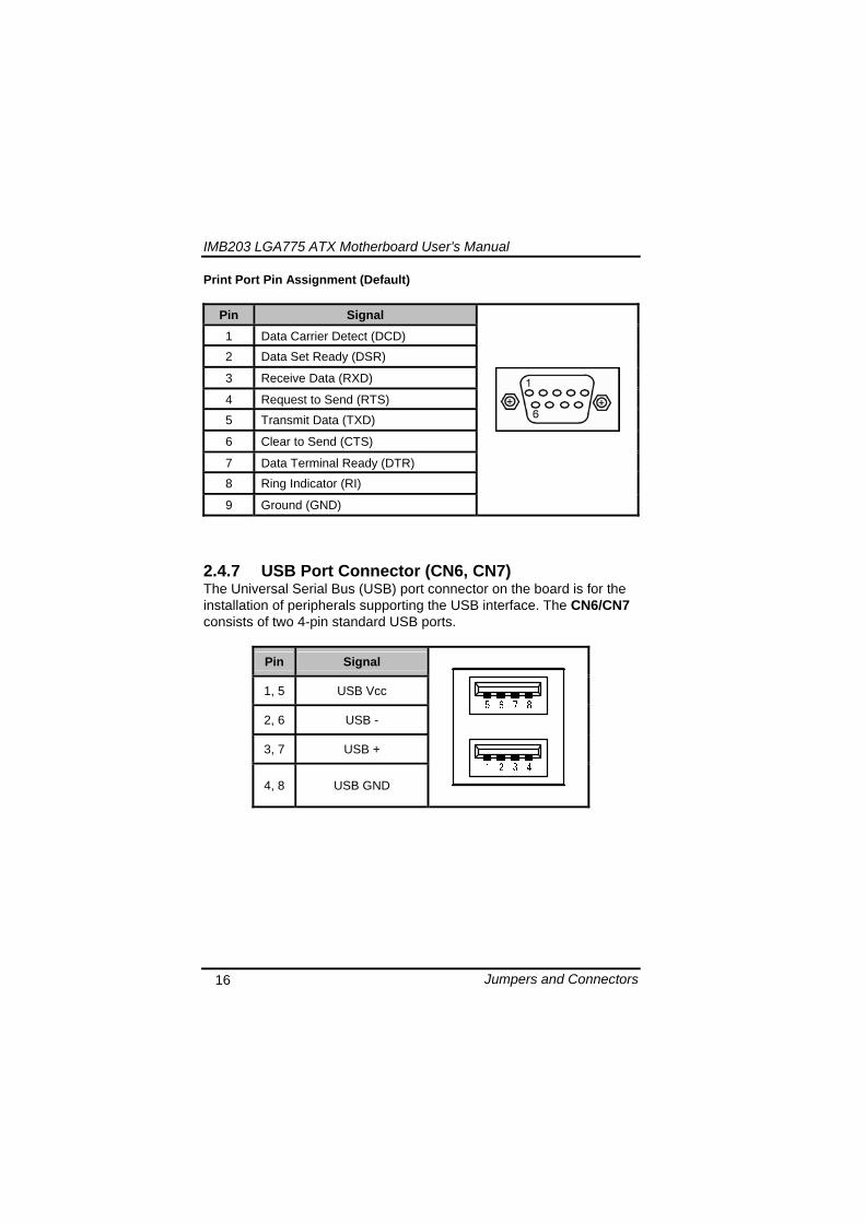
IMB203 LGA775 ATX Motherboard Userrsquos Manual
Jumpers and Connectors 17
248 USB Connectors (CN27 CN29 CN33 CN45) The 10-pin standard Universal Serial Bus (USB) connectors CN27293345 on this board are for installing versatile USB interface peripherals
Pin Signal Pin Signal 1 USB 2 USB
3 USB2- 4 USB3-
5 USB2+ 6 USB3+
7 GND 8 GND
9 GND 10 GND
CN45
Pin Signal Pin Signal 1 USB 2 USB
3 USB4- 4 USB5-
5 USB4+ 6 USB5+
7 GND 8 GND
10 GND
CN27 CN29 CN33
249 ATX 4 Pin 12V In Connector (CN14) You can connect it to the ATX12V power supply for CPU Core Voltage
Pin Signal 1 GND 2 GND 3 +12V 4 +12V
IMB203 LGA775 ATX Motherboard Userrsquos Manual
Jumpers and Connectors 18
2410 Digital IO Port (DIO) Connector (CN26) The board is equipped an 8-channel digital IO connector CN26 that meets requirements for a system customary automation control The digital IO can be configured to control cash drawers sense warning signals from an Uninterrupted Power System (UPS) or perform store security control The digital IO is controlled via software programming
Pin Signal Pin Signal
1 DO1 2 DI1
3 DO2 4 DI2
5 DO3 6 DI3
7 DO4 8 DI4
9 GND 10 GND
2411 CPU Fan Connector (CN31) A CPU fan is always needed for cooling CPU heat The CPU fan connector provides power to the CPU fan
Pin Signal 1 Ground 2 +12V 3 Rotation Detection4 Speed Control
2412 SATA Connectors (CN36 CN37 CN41 CN42
CN46 CN47) These SATA connectors are for high-speed SATA interface ports and they can be connected to hard disk devices
Pin Signal
1 GND
2 SATA_TX+
3 SATA_TX-
CN364146
IMB203 LGA775 ATX Motherboard Userrsquos Manual
Jumpers and Connectors 19
4 GND
5 SATA_RX-
6 SATA_RX+
7 GND
IMB203 LGA775 ATX Motherboard Userrsquos Manual
Jumpers and Connectors 20
2413 ATX Power Connector (CN50) Steady and sufficient power can be supplied to all components on the board by connecting the power connector Please make sure all components and devices are properly installed before connecting the power connector If you use a 24-pin ATX power supply please remove the small cover from the power connector before plugging in the power cord otherwise please do not remove it Pin Signal Pin Signal 1 33V 2 33V
3 GND 4 5V
5 GND 6 5V
7 GND 8 PWR
9 5VSB 10 12V
11 12V 12 33V
13 33V 14 -12V
15 GND 16 PS_ON
17 GND 18 GND
19 GND 20 -5V
21 5V 22 5V
23 5V 24 GND
IMB203 LGA775 ATX Motherboard Userrsquos Manual
Jumpers and Connectors 21
2414 Front Panel Connector (CN52)
Power LED
This 3-pin connector denoted as Pin 1 and Pin 5 connects the system power LED indicator to such a switch on the case Pin 1 is assigned as + and Pin 5 as - The Power LED lights up when the system is powered ON Pin 3 is defined as GND
External Speaker and Internal Buzzer Connector
Pin 2 4 6 and 8 can be connected to the case-mounted speaker unit or internal buzzer While connecting the CPU card to an internal buzzer please short pins 2-4 while connecting to an external speaker you need to set pins 2-4 to Open and connect the speaker cable to pin 8 (+) and pin 2 (-)
ATX Power OnOff Button
This 2-pin connector denoted as Pin 9 and 10 connects the front panelrsquos ATX power button to the CPU card which allows users to control ATX power supply to be power onoff
System Reset Switch
Pin 11 and 12 can be connected to the case-mounted reset switch that reboots your computer instead of turning OFF the power switch It is a better way to reboot your system for a longer life of the systemrsquos power supply
HDD Activity LED
This connection is linked to hard drive activity LED on the control panel LED flashes when HDD is being accessed Pin 13 and 14 connect the hard disk drive to the front panel HDD LED Pin 13 assigned as - and Pin 14 as +
IMB203 LGA775 ATX Motherboard Userrsquos Manual
Jumpers and Connectors 22
MEMO
IMB203 LGA775 ATX Motherboard Userrsquos Manual
Hardware Installation 23
CHAPTER 3 HARDWARE INSTALLATION
Before installing the processor please access Intelreg website for more detailed information httpwwwintelcom
31 Installing the Processor The LGA775 processor socket comes with a cover to protect the processor Please install the processor into the CPU socket step by step as below
Hold the hook (A) of the lever and push it down Pull the lever (B) aside to unlock the cover
IMB203 LGA775 ATX Motherboard Userrsquos Manual
Hardware Installation 24
Remove the plastic cap (E) from the cover
Open the cover (C) you can see the contact
Be careful not to touch the contact (D)
IMB203 LGA775 ATX Motherboard Userrsquos Manual
Hardware Installation 25
Place the CPU down into the socket Be careful not to touch the contact
Hold the edges of the CPU and orientate it as the marked direction (G) down into the socket to match the (H) and (F) locations
IMB203 LGA775 ATX Motherboard Userrsquos Manual
Hardware Installation 26
Slightly push down the cover and hook the lever (I~J) The CPU is completely locked
Orientate the CPU cooling fan to fixing holes on the board
IMB203 LGA775 ATX Motherboard Userrsquos Manual
Hardware Installation 27
Screw the CPU cooling fan onto the board
Make sure the CPU fan is plugged to the CPU fan connector
IMB203 LGA775 ATX Motherboard Userrsquos Manual
Hardware Installation 28
32 Installing the Memory The board supports four 240-pin DDR3 DIMM memory sockets with maximum memory capacity up to 16GB Please follow steps below to install the memory modules 1 Push down latches on each side of the DIMM socket 2 Align the memory module with the socket that notches of
memory module must match the socket keys for a correct installation
3 Install the memory module into the socket and push it firmly down until it is fully seated The socket latches are levered upwards and clipped on to the edges of the DIMM
4 Install any remaining DIMM modules
IMB203 LGA775 ATX Motherboard Userrsquos Manual
Hardware Description 29
CHAPTER 4 HARDWARE DESCRIPTION
41 Microprocessors The IMB203 Series supports Intelreg Coretrade 2 Quad Coretrade 2 Duo processors which make your system operated under Windowsreg XP and Linux environments The system performance depends on the microprocessor Make sure all correct settings are arranged for your installed microprocessor to prevent the CPU from damages
42 BIOS The IMB203 Series uses AMI Plug and Play BIOS with a single 32Mbit SPI Flash
43 System Memory The IMB203 Series supports four 240-pin DDR3 DIMM sockets for a maximum memory of 16GB DDR3 SDRAMs The memory module can come in sizes of 1GB 2GB and 4GB
IMB203 LGA775 ATX Motherboard Userrsquos Manual
Hardware Description 30
44 IO Port Address Map The Intelreg Coretrade 2 Extreme Intelreg Coretrade 2 Quad Coretrade 2 Duo CPUs can communicate via IO ports There are total 1KB port addresses available for assignment to other devices via IO expansion cards
Address Devices 000-01F DMA controller 1
020-02D 024-025 028-029 02C-02D Interrupt controller 1
02E-02F Forwarded to LPC(LPC Super IO ) 030-031 034-035 038-039 03C-03D
Interrupt controller 2
040-043 050-053 TimerCounter (8254) 060 Forwarded to LPC (Microcontroller) 061 NMI
062-066 Forwarded to LPC (Microcontroller) 070-077 Real time clock NMI 080-091 DMA page register
092 Processor IF(Reset Generator) 093-09F DMA page register 0A0-0BF Interrupt controller 2 0C0-0DF DMA controller 2
0F0 Processor IF 0F8-0FF Math processor 170-177 Forward to SATA (SATA Controller) 1F0-1F7 Forward to SATA (SATA Controller)
376 Forward to SATA(SATA Controller) 378-37F Parallel Port (LPT) 380-38F SDLC 2 3A0-3AF SDLC 1 3B0-3BF MDA video card
(to be continued)
IMB203 LGA775 ATX Motherboard Userrsquos Manual
Hardware Description 31
Address Devices 3C0-3CF EGA card 3D0-3DF CGA card
3F6 Forward to SATA(SATA Controller) 3F8-3FF Serial port 1 (COM1) 2F8-2FF Serial port 2 (COM2)
45 Interrupt Controller (IRQ) Map The IMB203 Series is a 100 PC compatible control board It consists of 16 interrupt request lines and four out of them can be programmable The mapping list of the 16 interrupt request lines is shown as the following table
IRQ Parity check error IRQ0 System Timer Output
IRQ1 Keyboard
IRQ2 Interrupt rerouting from IRQ8 through IRQ15
IRQ3 Serial port 2
IRQ4 Serial port 1
IRQ5 PCI Device Share
IRQ7 Parallel port
IRQ8 Real time clock
IRQ9 ACPI Controller
IRQ10 PCI Device Share
IRQ11 PCI Device Share
IRQ12 PS2 Mouse
IRQ13 Math coprocessor
IRQ14 SATA Primary (Legacy Mode)
IRQ15 SATA Secondary (Legacy Mode)
IMB203 LGA775 ATX Motherboard Userrsquos Manual
Hardware Description 32
MEMO
IMB203 LGA775 ATX Motherboard Userrsquos Manual
AMI BIOS Setup Utility 33
CHAPTER 5 AMI BIOS SETUP UTILITY
This chapter provides users with detailed description how to set up basic system configuration through the AMIBIOS8 BIOS setup utility 51 Starting To enter the setup screens follow the steps below 1 Turn on the computer and press the ltDelgt key immediately 2 After you press the ltDeletegt key the main BIOS setup menu
displays You can access the other setup screens from the main BIOS setup menu such as the Chipset and Power menus
52 Navigation Keys The BIOS setuputility uses a key-based navigation system called hot keys Most of the BIOS setup utility hot keys can be used at any time during the setup navigation process These keys include ltF1gt ltF10gt ltEntergt ltESCgt ltArrowgt keys and so on
Note Some of navigation keys differ from one screen to another
IMB203 LGA775 ATX Motherboard Userrsquos Manual
AMI BIOS Setup Utility 34
LeftRight The Left ltArrowgt keys allow you to select a setup screen
UpDown The Up and Down ltArrowgt keys allow you to select a setup screen or sub-screen
+minus PlusMinus The Plus and Minus ltArrowgt keys allow you to change the field value of a particular setup item
Tab The ltTabgt key allows you to select setup fields
F1 The ltF1gt key allows you to display the General Help screen
F10 The ltF10gt key allows you to save any changes you have made and exit Setup Press the ltF10gt key to save your changes
Esc
The ltEscgt key allows you to discard any changes you have made and exit the Setup Press the ltEscgt key to exit the setup without saving your changes
Enter
The ltEntergt key allows you to display or change the setup option listed for a particular setup item The ltEntergt key can also allow you to display the setup sub- screens
IMB203 LGA775 ATX Motherboard Userrsquos Manual
AMI BIOS Setup Utility 35
53 Main Menu When you first enter the Setup Utility you will enter the Main setup screen You can always return to the Main setup screen by selecting the Main tab There are two Main Setup options They are described in this section The Main BIOS Setup screen is shown below
System TimeDate
Use this option to change the system time and date Highlight System Time or System Date using the ltArrowgt keys Enter new values through the keyboard Press the ltTabgt key or the ltArrowgt keys to move between fields The date must be entered in MMDDYY format The time is entered in HHMMSS format
IMB203 LGA775 ATX Motherboard Userrsquos Manual
AMI BIOS Setup Utility 36
54 Advanced Menu The Advanced menu allows users to set configuration of the CPU and other system devices You can select any of the items in the left frame of the screen to go to the sub menus
CPU Configuration IDE Configuration SuperIO Configuration Hardware Health Configuration ACPI Configuration AHCI Configuration Intel iAMT Configuration Intel VT-d Configuration MPS Configuration PCI Express Configuration Trusted Computing USB Configuration
For items marked with ldquo rdquo please press ltEntergt for more options
IMB203 LGA775 ATX Motherboard Userrsquos Manual
AMI BIOS Setup Utility 37
CPU Configuration This screen shows the CPU Configuration and you can change the value of the selected option
Max CPUID Value Limit
You can enable this item to let legacy operating systems boot even without support for CPUs with extended CPU ID functions
Execute-Disable Bit Capability This item helps you enable or disable the No-Execution Page Protection Technology
Core Multi-Processing This feature controls the functionality of the Core Multi-Processing to allow the processor to execute multitasking function
PECI Use this item PECI (Platform Environment Control Interface) to execute the processor temperature monitoring and management
IMB203 LGA775 ATX Motherboard Userrsquos Manual
AMI BIOS Setup Utility 38
Intel (R) C-STATE tech Use this item to enable or disable the C-State technology
IDE Configuration You can use this screen to select options for the IDE Configuration and change the value of the selected option A description of the selected item appears on the right side of the screen For items marked with ldquo rdquo please press ltEntergt for more options
SATA1 Configuration
Use this item to control the onboard SATA controller Here are the options for your selection Compatible Disabled and Enhanced
Configure SATA1 as Use this item to choose the SATA operation mode Here are the options for your selection IDE and AHCI
SATA2 Configuration Use this item to control the onboard SATA controller Here are the options for your selection Enhanced and Disabled
IMB203 LGA775 ATX Motherboard Userrsquos Manual
AMI BIOS Setup Utility 39
PrimarySecondaryThird IDE Master Select one of the hard disk drives to configure IDE devices installed in the system by pressing ltEntergt for more options
Fifth IDE Master Select one of the hard disk drives to configure IDE devices installed in the system by pressing ltEntergt for more options
IMB203 LGA775 ATX Motherboard Userrsquos Manual
AMI BIOS Setup Utility 40
SuperIO Configuration You can use this screen to select options for the SuperIO Configuration and change the value of the selected option A description of the selected item appears on the right side of the screen
Serial Port1 Address
This option specifies the base IO port address and Interrupt Request address of serial port 1 The Optimal setting is 3F8IRQ4 The Fail-Safe default setting is Disabled
Serial Port2 Address This option specifies the base IO port address and Interrupt Request address of serial port 2 The Optimal setting is 2F8IRQ3 The Fail-Safe setting is Disabled
Parallel Port Address This item allows you to determine the IO address for onboard parallel port There are several options for your selection
Parallel Port Mode
IMB203 LGA775 ATX Motherboard Userrsquos Manual
AMI BIOS Setup Utility 41
Select an operating mode for the onboard parallel (printer) port
Parallel Port IRQ Use this item to set up the IRQ for onboard parallel port
Serial Port3 Address This item specifies the base IO port address and Interrupt Request address of serial port 3 The Optimal setting is 3E8IRQ11 The Fail-Safe default setting is Disabled
Serial Port3 IRQ This item specifies the IRQ used by the serial port 3
Serial Port4 Address This item specifies the base IO port address and Interrupt Request address of serial port 4 The Optimal setting is 2E8IRQ10 The Fail-Safe default setting is Disabled
Serial Port4 IRQ This item specifies the IRQ used by the serial port 4
IMB203 LGA775 ATX Motherboard Userrsquos Manual
AMI BIOS Setup Utility 42
Hardware Health Configuration This screen shows the Hardware Health Configuration and a description of the selected item appears on the right side of the screen
HW Health Configuration
This screen displays the temperature of CPU and System Fan Speed Vcore etc
IMB203 LGA775 ATX Motherboard Userrsquos Manual
AMI BIOS Setup Utility 43
ACPI Configuration You can use this screen to select options for the ACPI Configuration and change the value of the selected option A description of the selected item appears on the right side of the screen
General ACPI Configuration
Scroll to this item and press ltEntergt to view the General ACPI Configuration sub menu which contains General ACPI (Advanced Configuration and Power Management Interface) options for your configuration
Advanced ACPI Configuration Scroll to this item and press ltEntergt to view the Advanced ACPI Configuration sub menu which contains Advanced ACPI (Advanced Configuration and Power Management Interface) options for your configuration
Chipset ACPI Configuration Scroll to this item and press ltEntergt to view the Chipset ACPI Configuration sub menu which contains Chipset ACPI (Advanced Configuration and Power Management
IMB203 LGA775 ATX Motherboard Userrsquos Manual
AMI BIOS Setup Utility 44
Interface) options for your configuration AHCI Configuration
You can use this screen to select options for the AHCI Configuration and change the value of the selected option A description of the selected item appears on the right side of the screen
AHCI BIOS Support You can enable or disable this item to control the AHCI function of the SATA controller
IMB203 LGA775 ATX Motherboard Userrsquos Manual
AMI BIOS Setup Utility 45
Intel iAMT Configuration You can use this screen to select options for the Intel iAMT Configuration and change the value of the selected option A description of the selected item appears on the right side of the screen
Intel iAMT Support
You can enable this item to support iAMT (active management technology) function to follow up the procedure for the access to AMI program screen
Unconfigure iAMTME Use this item to unconfigure the iAMTME settings
IMB203 LGA775 ATX Motherboard Userrsquos Manual
AMI BIOS Setup Utility 46
Intel VT-d Configuration You can use this screen to select options for the Intel VT-d Configuration and change the value of the selected option A description of the selected item appears on the right side of the screen
Intel VT-d Virtualization Technology for Directed IO (VT-d) extends Virtualization Technology (VT) roadmap by providing hardware assists for virtualization solution VT-d can help end users improve security and reliability of the systems and also improve performance of IO devices in virtualized environment Here are the options for your selection Disabled and Enabled
IMB203 LGA775 ATX Motherboard Userrsquos Manual
AMI BIOS Setup Utility 47
Remote Access Configuration You can use this screen to select options for the Remote Access Configuration and change the value of the selected option A description of the selected item appears on the right side of the screen
Remote Access Use this item to enable or disable the Remote Access function
IMB203 LGA775 ATX Motherboard Userrsquos Manual
AMI BIOS Setup Utility 48
PCI Express Configuration This screen shows the PCI Express Configuration and you can change its value A description of the selected item appears on the right side of the screen
Active State Power-Management
Use this item to enable or disable the function of Active State Power-Management to provide you with lower power consumption The default setting is Disabled
IMB203 LGA775 ATX Motherboard Userrsquos Manual
AMI BIOS Setup Utility 49
Trusted Computing You can use this screen to select options for the Trusted Computing and change the value of the selected option A description of the selected item appears on the right side of the screen
TCGTPM SUPPORT Use this item to control the Trusted Platform Module (TPM) function
IMB203 LGA775 ATX Motherboard Userrsquos Manual
AMI BIOS Setup Utility 50
USB Configuration You can use this screen to select options for the USB Configuration and change the value of the selected option A description of the selected item appears on the right side of the screen
USB Functions
This item allows you to enable or disable USB functions
Legacy USB Support Use this item to enable or disable support for USB device on legacy operating system The default setting is Enabled
USB 20 Controller Mode Use this item to configure the USB 20 controller The default setting is HiSpeed
BIOS EHCI Hand-Off Enabling this item provide the support for operating systems without an EHCI hand-off feature The default setting is Enabled
IMB203 LGA775 ATX Motherboard Userrsquos Manual
AMI BIOS Setup Utility 51
IMB203 LGA775 ATX Motherboard Userrsquos Manual
AMI BIOS Setup Utility 52
55 PCI PnP Menu The PCI PnP menu allows users to change the advanced settings for PCIPnP devices
Clear NVRAM
Use this item to clear the data in the NVRAM (CMOS) Here are the options for your selection No and Yes
Plug amp Play OS When the setting is No Use this item to configure all the devices in the system When the setting is Yes and if you install a Plug and Play operating system the operating system configures the Plug and Play devices not required for boot The default setting is No
IMB203 LGA775 ATX Motherboard Userrsquos Manual
AMI BIOS Setup Utility 53
PCI Latency Timer This item controls how long a PCI device can hold the PCI bus before another takes over The longer the latency the longer the PCI device can retain control of the bus before handing it over to another PCI device There are several options for your selection
Allocate IRQ to PCI VGA This item allows BIOS to choose an IRQ to assign for the PCI VGA card Here are the options for your selection No and Yes
Palette Snooping Some old graphic controllers need to ldquosnooprdquo on the VGA palette and then map it to their display as a way to provide boot information and VGA compatibility This item allows such snooping to take place Here are the options for your selection Disabled and Enabled
PCI IDE BusMaster This item is a toggle for the built-in driver that allows the onboard IDE controller to perform DMA (Direct Memory Access) transfer Here are the options for your selection Disabled and Enabled
OffBoard PCIISA IDE Card This item is for any other non-onboard PCIISA IDE controller adapter There are several options for your selection
IRQ3457910111415 These items will allow you to assign each system interrupt a type depending on the type of device using the interrupt The option ldquoAvailablerdquo means the IRQ is going to assign automatically Here are the options for your selection Available and Reserved
DMA Channel 013567 These items will allow you to assign each DMA channel a type depending on the type of device using the channel The option ldquoAvailablerdquo means the channel is going to assign automatically Here are the options for your selection Available and Reserved
IMB203 LGA775 ATX Motherboard Userrsquos Manual
AMI BIOS Setup Utility 54
56 Boot Menu The Boot menu allows users to change boot options of the system You can select any of the items in the left frame of the screen to go to the sub menus
Boot Settings Configuration Boot Device Priority Removable Drives
For items marked with ldquo rdquo please press ltEntergt for more options
IMB203 LGA775 ATX Motherboard Userrsquos Manual
AMI BIOS Setup Utility 55
Boot Settings Configuration
Quick Boot
Enabling this item lets the BIOS skip some power on self tests (POST) The default setting is Enabled
AddOn ROM Display Mode This item selects the display mode for option ROM The default setting is Force BIOS
Boot Num-Lock Use this item to select the power-on state for the NumLock The default setting is On
PS2 Mouse Support This item determines if the BIOS should reserve IRQ12 for the PS2 mouse or allow other devices to make use of this IRQ Here are the options for your selection Auto Enabled and Disabled
Wait For lsquoF1rsquo Of Error If this item is enabled the system waits for the F1 key to be pressed when error occurs The default setting is Enabled
Hit lsquoDELrsquo Message Display If this item is enabled the system displays the message
IMB203 LGA775 ATX Motherboard Userrsquos Manual
AMI BIOS Setup Utility 56
ldquoPress DEL to run Setuprdquo during POST The default setting is Enabled
Interrupt 19 Capture If this item is enabled this function makes the option ROMs to trap Interrupt 19 The default setting is Disabled
Boot Device Priority The Boot Device Priority screen specifies the boot device priority sequence from the available devices
IMB203 LGA775 ATX Motherboard Userrsquos Manual
AMI BIOS Setup Utility 57
Removable Drives Use this screen to view the removable drives in the system The BIOS will attempt to arrange the removable drive boot sequence automatically You can also change the booting sequence
IMB203 LGA775 ATX Motherboard Userrsquos Manual
AMI BIOS Setup Utility 58
57 Security Menu The Security menu allows users to change the security settings for the system
Supervisor Password
This item indicates whether a supervisor password has been set If the password has been installed Installed displays If not Not Installed displays
User Password This item indicates whether a user password has been set If the password has been installed Installed displays If not Not Installed displays
Change Supervisor Password Select this option and press ltEntergt to access the sub menu You can use the sub menu to change the supervisor password
Change User Password Select this option and press ltEntergt to access the sub menu You can use the sub menu to change the user password
IMB203 LGA775 ATX Motherboard Userrsquos Manual
AMI BIOS Setup Utility 59
58 Chipset Menu The Chipset menu allows users to change the advanced chipset settings You can select any of the items in the left frame of the screen to go to the sub menus
North Bridge Configuration South Bridge Configuration ME Subsystem Configuration
For items marked with ldquo rdquo please press ltEntergt for more options
IMB203 LGA775 ATX Motherboard Userrsquos Manual
AMI BIOS Setup Utility 60
North Bridge Configuration
Memory Remap Feature
Use this item to enable or disable the remapping of the overlapped PCI memory above the total physical memory Only 64-bit OS supports this function
DRAM Frequency This item allows you to control the Memory Clock
Configure DRAM Timing by SPD This item can enable or disable DRAM timing by SPD (Serial Presence Detect) device which is a small EEPROM chip on the memory module containing important information about the module speed size addressing mode and various parameters
Memory Hole You can reserve this area of system memory for ISA adapter ROM When this area is reserved it cannot be cached Check the user information of peripherals that need to use this area o f system memory for the memory requirements Here are the options Disabled and 15M-16M
IMB203 LGA775 ATX Motherboard Userrsquos Manual
AMI BIOS Setup Utility 61
Initiate Graphic Adapter When using multiple graphics cards this item can select which graphics controller to be the primary display device during boot
IGD Graphics Mode Select This item allows you to select the amount of system memory used by the internal graphics device
PEG Port ConfigurationPEG Port This item is a toggle to enable or disable the PCI Express port Here are the options for your selection Auto and Disabled
Video Function Configuration Press ltEntergt for the sub-menu for setting up video function
IMB203 LGA775 ATX Motherboard Userrsquos Manual
AMI BIOS Setup Utility 62
South Bridge Configuration
GbE Wake Up From S5 This item specifies whether the system will be awakened from the S5 power
HDA Controller This item allows you to enable or disable the HD audio support
Restore on AC Power Loss This item can control how the PC will behave once power is restored following a power outage or other unexpected shutdown
PCIE Port Configuration This item allows you to set or disable the PCI Express Ports
IMB203 LGA775 ATX Motherboard Userrsquos Manual
AMI BIOS Setup Utility 63
ME Subsystem Configuration
It is strongly recommended that you do not modify these options unless you are an advanced user
IMB203 LGA775 ATX Motherboard Userrsquos Manual
AMI BIOS Setup Utility 64
59 Exit Menu The Exit menu allows users to load your system configuration with optimal or failsafe default values
Save Changes and Exit
When you have completed the system configuration changes select this option to leave Setup and reboot the computer so the new system configuration parameters can take effect Select Save Changes and Exit from the Exit menu and press ltEntergt Select Ok to save changes and exit
Discard Changes and Exit Select this option to quit Setup without making any permanent changes to the system configuration Select Discard Changes and Exit from the Exit menu and press ltEntergt Select Ok to discard changes and exit
Load Optimal Defaults It automatically sets all Setup options to a complete set of default settings when you select this option The Optimal settings are designed for maximum system performance but may not work best for all computer applications In particular do not use the Optimal Setup options if your
IMB203 LGA775 ATX Motherboard Userrsquos Manual
AMI BIOS Setup Utility 65
computer is experiencing system configuration problems Select Load Optimal Defaults from the Exit menu and press ltEntergt
Load Fail-Safe Defaults It automatically sets all Setup options to a complete set of default settings when you select this option The Fail-Safe settings are designed for maximum system stability but not maximum performance Select the Fail-Safe Setup options if your computer is experiencing system configuration problems Select Load Fail-Safe Defaults from the Exit menu and press ltEntergt Select Ok to load Fail-Safe defaults
IMB203 LGA775 ATX Motherboard Userrsquos Manual
AMI BIOS Setup Utility 66
MEMO
IMB203 LGA775 ATX Motherboard Userrsquos Manual
Installation of Drivers 67
CHPATER 6 INSTALLATION OF DRIVERS
The device drivers are located on the Product Information CD-ROM that comes with the IMB203 Series package The auto-run function of drivers will guide you to install the utilities and device drivers under a Windows system You can follow the onscreen instructions to install these devices
Chipse VGA LAN Audio iAMT MEI
61 Installing Chipset Driver 1 Run the SETUPEXE program from the driver directory in
your driver CD Click ldquoNextrdquo to next step
IMB203 LGA775 ATX Motherboard Userrsquos Manual
Installation of Drivers 68
2 An Intelreg License Agreement appears to show you the important information Click ldquoYesrdquo to next step
3 Refer to the Readme file below to view the system requirements and installation information
IMB203 LGA775 ATX Motherboard Userrsquos Manual
Installation of Drivers 69
3-1 Please wait while running the following setup operations
3-2 Please wait while running the following setup operations
IMB203 LGA775 ATX Motherboard Userrsquos Manual
Installation of Drivers 70
4 Click ldquoFinishrdquo to complete the setup process
5 You will be asked to reboot your computer when the installation is completed Please click ldquoYes I want to restart my computer nowrdquo if you donrsquot need to install any other drivers Otherwise please click ldquoNo I will restart my computer laterrdquo and go on next step
IMB203 LGA775 ATX Motherboard Userrsquos Manual
Installation of Drivers 71
62 Installing VGA Driver 1 Run the SETUPEXE program from the driver directory in
your driver CD Click ldquoNextrdquo to next step
2 An Intelreg License Agreement appears to show you the
important information Click ldquoYesrdquo to next step
IMB203 LGA775 ATX Motherboard Userrsquos Manual
Installation of Drivers 72
3 The message of Readme File Information appears to show you the system requirements and installation information Please click ldquoNextrdquo
4 Please wait while running the following setup operations
When this message appears please click ldquoNextrdquo
IMB203 LGA775 ATX Motherboard Userrsquos Manual
Installation of Drivers 73
5 Click ldquoFinishrdquo to complete the setup process
6 You will be asked to reboot your computer when the installation is completed Please click ldquoYes I want to restart my computer nowrdquo if you donrsquot need to install any other drivers Otherwise please click ldquoNo I will restart my computer laterrdquo and click ldquoFinishrdquo to complete the installation
IMB203 LGA775 ATX Motherboard Userrsquos Manual
Installation of Drivers 74
63 Installing LAN Driver
11 Run the InstallShield Wizard for Network Connections from
the driver directory in your driver CD Click ldquoNextrdquo to next step
IMB203 LGA775 ATX Motherboard Userrsquos Manual
Installation of Drivers 75
12 An Intelreg License Agreement appears to show you the important information Click ldquoYesrdquo to next step
13 A Setup Options window appears that you can select the
program features you want to install
IMB203 LGA775 ATX Motherboard Userrsquos Manual
Installation of Drivers 76
2 Click ldquoInstallrdquo to start the installation
3 Please wait while running the following installation operation
IMB203 LGA775 ATX Motherboard Userrsquos Manual
Installation of Drivers 77
4 Click ldquoFinishrdquo to complete the installation
Note The Driver item [Wake on Directed Packet] default is Enabled under Windows Vista
格式化 字型 (符號) Arial
格式化 字型 (符號) Arial
格式化 字型 斜體 字型色彩 黑色 (符號) Arial 非加寬 緊縮
格式化 字型 斜體 字型色彩 黑色 (符號) Arial 非加寬 緊縮
格式化 字型 (符號) Arial 非加寬 緊縮
IMB203 LGA775 ATX Motherboard Userrsquos Manual
Installation of Drivers 78
64 Installing AUDIO Driver 1 Run the InstallShield Wizard for Realtek High Definition
Audio Driver from the driver directory in your driver CD Click ldquoNextrdquo to next step
IMB203 LGA775 ATX Motherboard Userrsquos Manual
Installation of Drivers 79
2 Click ldquoInstallrdquo to start the installation and wait while running the installation operation
3 Click ldquoFinishrdquo to complete the installation
IMB203 LGA775 ATX Motherboard Userrsquos Manual
Installation of Drivers 80
65 Installing iAMT (Active Management Technology) Driver
Note You must download and properly install the required NET version 35 provided from a separate downloading of the actual FimwareTools kit releases posted on VIP prior to loading the MEILMS Driver stack
651 LMS_SOL Setup
1 Run the setup program to install Intelreg Active Management Technology onto your computer It is strongly recommended that you exit all programs before continuing Click ldquoNextrdquo to next step
格式化 字型 (符號) Arial
格式化 字型 (符號) Arial 非加寬 緊縮
IMB203 LGA775 ATX Motherboard Userrsquos Manual
Installation of Drivers 81
2 An Intelreg license agreement appears that you need to continue the setup program by clicking ldquoYesrdquo to accept the terms
IMB203 LGA775 ATX Motherboard Userrsquos Manual
Installation of Drivers 82
3 Refer to the Readme file below to view the system requirements and installation information Click ldquoNextrdquo to next setup
4 Please wait while running the following installation operation
IMB203 LGA775 ATX Motherboard Userrsquos Manual
Installation of Drivers 83
5 Click ldquoFinishrdquo to complete the installation
IMB203 LGA775 ATX Motherboard Userrsquos Manual
Installation of Drivers 84
652 LMS_SOL_IS Setup
1 Run the setup program to install Intelreg Active Management Technology onto your computer It is strongly recommended that you exit all programs before continuing Click ldquoNextrdquo to next step
IMB203 LGA775 ATX Motherboard Userrsquos Manual
Installation of Drivers 85
2 An Intelreg license agreement appears that you need to continue the setup program by clicking ldquoYesrdquo to accept the terms
IMB203 LGA775 ATX Motherboard Userrsquos Manual
Installation of Drivers 86
3 Refer to the Readme file below to view the system requirements and installation information Click ldquoNextrdquo to next setup
4 Please wait while running the following installation operation
IMB203 LGA775 ATX Motherboard Userrsquos Manual
Installation of Drivers 87
5 Click ldquoFinishrdquo to complete the installation
IMB203 LGA775 ATX Motherboard Userrsquos Manual
Installation of Drivers 88
66 Installing MEI (Management Engine Interface) Driver
Note You must download and properly install the required NET version 35 provided from a separate downloading of the actual FimwareTools kit releases posted on VIP prior to loading the MEILMS Driver stack
1 Run the setup program to install Intelreg Management Engine
Interface onto your computer It is strongly recommended that you exit all programs before continuing Click ldquoNextrdquo to next step
格式化 字型 (符號) Arial
格式化 字型 (符號) Arial 非加寬 緊縮
IMB203 LGA775 ATX Motherboard Userrsquos Manual
Installation of Drivers 89
2 An Intelreg license agreement appears that you need to continue the setup program by clicking ldquoYesrdquo to accept the terms
IMB203 LGA775 ATX Motherboard Userrsquos Manual
Installation of Drivers 90
3 Refer to the Readme file below to view the system requirements and installation information Click ldquoNextrdquo to next setup
4 Please wait while running the following installation operation
IMB203 LGA775 ATX Motherboard Userrsquos Manual
Installation of Drivers 91
5 Click ldquoFinishrdquo to complete the installation
IMB203 LGA775 ATX Motherboard Userrsquos Manual
Installation of Drivers 92
MEMO
IMB203 LGA775 ATX Motherboard Userrsquos Manual
Watchdog Timer 93
APPENDIX A WATCHDOG TIMER
Watchdog Timer Setting After the system stops working for a while it can be auto-reset by the Watchdog Timer The integrated Watchdog Timer can be set up in the system reset mode by program
Using the Watchdog Function Start darr Un-Lock WDT O 2E 87 Un-lock super IO
O 2E 87 Un-lock super IO darr Set WDT Function O 2E 2D O 2F 20 Select Logic device O 2E 07 O 2F 08 darr Activate WDT O 2E 30
O 2F 01 Set Second or Minute O 2E F5
O 2F N N=00 or 08(See below table) darr Set base timer O 2E F6
O 2F M=000102hellipFF(Hex) Value=0 to 255 darr WDT counting
re-set timer O 2E F6
O 2F M M=000102hellipFF(See below table) darr
格式化
格式化 項目符號及編號
格式化 項目符號及編號
格式化 字型 8 點 字型色彩黑色
格式化 字型 8 點 字型色彩黑色
格式化 定位點 1257 字元左 + 不在 1012 字元 + 1386字元
格式化 字型 8 點 字型色彩黑色
格式化 定位點 1257 字元左 + 不在 134 字元 + 1362字元
格式化 字型色彩 黑色
格式化 字型色彩 黑色
刪除
IMB203 LGA775 ATX Motherboard Userrsquos Manual
Watchdog Timer 94
IF No re-set timer WDT time-out generate RESET IF to disable WDT O 2E 30
O 2F 00 Can be disable at any time
N=00
M= 00h Time-out Disable 01h Time-out occurs after 1 second 02h Time-out occurs after 2 second 03h Time-out occurs after 3 second helliphelliphelliphelliphelliphelliphelliphelliphellip FFh Time-out occurs after 255 second
N=08
M= 00h Time-out Disable 01h Time-out occurs after 1 minute 02h Time-out occurs after 2 minutes 03h Time-out occurs after 3 minutes helliphelliphelliphelliphelliphelliphelliphelliphellip
FFh Time-out occurs after 255 minutes
格式化 字型色彩 黑色
格式化 字型色彩 黑色
IMB203 LGA775 ATX Motherboard Userrsquos Manual
PCI IRQ Routing 95
APPENDIX B PCI IRQ ROUTING
PICMG PCI IRQ Routing
Device ID Slot Int
PCI Slot 0 31 0 BCDA PCI Slot 1 30 1 CDAB PCI Slot 2 29 2 DABC PCI Slot 3 28 3 ABCD
IMB203 LGA775 ATX Motherboard Userrsquos Manual
PCI IRQ Routing 96
MEMO
IMB203 LGA775 ATX Motherboard Userrsquos Manual
Configuring SATA for RAID Function 97
APPENDIX C CONFIGURING SATA FOR RAID
FUNCTION
Configuring SATA Hard Drive(s) for RAID Function (Controller IntelregICH10DODO DH only) Please follow up the steps below to configure SATA hard drive(s) (1) Install SATA hard drive(s) in your system (2) Enter the BIOS Setup to configure SATA controller mode and boot
sequence (3) Configure RAID by the RAID BIOS (4) Install the SATA controller driver during the OS installation Before you begin the SATA configuration please prepare (a) Two SATA hard drives (to ensure optimal performance it is
recommended that you use two hard drives with identical model and capacity) If you do not want to create RAID with the SATA controller you may prepare only one hard drive
(b) An empty formatted floppy disk (c) Windows XP setup disk (1) Installing SATA hard drive(s) in your system
Connect one end of the SATA signal cable to the rear of the SATA hard drive and the other end to available SATA port(s) on the board Then connect the power connector of power supply to the hard drive
(2) Configuring SATA controller mode and boot sequence by the BIOS Setup You have to make sure whether the SATA controller is configured correctly by system BIOS Setup and set up BIOS boot sequence for the SATA hard drive(s)
IMB203 LGA775 ATX Motherboard Userrsquos Manual
Configuring SATA for RAID Function 98
(2)-1-1 Turn on your system and then press the Del button to enter BIOS Setup during running POST (Power-On Self Test) If you want to create RAID just go to the Advanced Settings menuIDE configuration select the Configure SATA1 as and press ltEntergt for more options
IMB203 LGA775 ATX Motherboard Userrsquos Manual
Configuring SATA for RAID Function 99
(2)-1-2 A list of options appears please select RAID
IMB203 LGA775 ATX Motherboard Userrsquos Manual
Configuring SATA for RAID Function 100
(2)-2 Set CDROM for First Boot Device under the Boot Settings menu to boot CD-ROM after system restarts
(2)-3 Save and exit the BIOS Setup
IMB203 LGA775 ATX Motherboard Userrsquos Manual
Configuring SATA for RAID Function 101
(3) Configuring RAID by the RAID BIOS Enter the RAID BIOS setup utility to configure a RAID array Skip this step and proceed to Section 4 if you do not want to create a RAID (3)-1 After the POST memory testing and before the operating
system booting a message Press ltCtrl-Igt to enter Configuration Utility shows up accordingly press ltCTRL+ Igt to enter the RAID BIOS setup utility
(3)-2 After you press ltCTRL+ Igt the Create RAID Volume screen will appear If you want to create a RAID array select the Create RAID Volume option in the Main Menu and press ENTER
IMB203 LGA775 ATX Motherboard Userrsquos Manual
Configuring SATA for RAID Function 102
(3)-3-1 After entering the CREATE VOLUME MENU screen you can type the disk array name with 1~16 letters (letters cannot be special characters) in the item ldquoNamerdquo
(3)-3-2 When finished press ENTER to select a RAID level There are three RAID levels RAID0 RAID1 and RAID5 amp RAID10 Select a RAID level and press ENTER
IMB203 LGA775 ATX Motherboard Userrsquos Manual
Configuring SATA for RAID Function 103
(3)-4 Set the stripe block size The KB is the standard unit of stripe block size The stripe block size can be 4KB to 128KB After the setting press ENTER for the array capacity
(3)-5 After setting all the items on the menu select Create Volume
and press ENTER to start creating the RAID array
IMB203 LGA775 ATX Motherboard Userrsquos Manual
Configuring SATA for RAID Function 104
(3)-6 When prompting the confirmation press ldquoYldquo to create this volume or ldquoNldquo to cancel the creation
After the creation is completed you can see detailed information about the RAID Array in the DISKVOLUME INFORMATION section including RAID mode disk block size disk name and disk capacity etc
IMB203 LGA775 ATX Motherboard Userrsquos Manual
Configuring SATA for RAID Function 105
Delete RAID Volume If you want to delete a RAID volume select the Delete RAID Volume option in Main Menu Press ENTER and follow on-screen instructions
Please press [ESC] to exit the RAID BIOS utility Now you can proceed to install a SATA driver controller and the operating system
IMB203 LGA775 ATX Motherboard Userrsquos Manual
Configuring SATA for RAID Function 106
(4) Making a SATA Driver Disk To install the operating system onto a serial ATA hard disk successfully you need to install the SATA controller driver during the OS installation Without the driver the hard disk may not be recognized during the Windows setup process First of all please format a blank floppy disk Secondly follow up these steps below to produce a SATA driver disk Users can insert the Driver CD and the formatted blank floppy disk in another system And then please copy all of file of the f6flpy32 folder in the Driver CD to a floppy disk Note Please copy all of file of the f6flpy64 folder if installing 64-bit
Windows Operating System
IMB203 LGA775 ATX Motherboard Userrsquos Manual
Configuring SATA for RAID Function 107
(5) Installing the SATA controller driver during the OS installation Now the SATA driver disk is ready and BIOS settings configured you can proceed to install Windows 2000XP onto your SATA hard drive using the SATA driver Here is an example for Windows XP installation (5)-1 Restart your system to boot the Windows 2000XP Setup disk
and press F6 button as soon as you see the message Press F6 if you need to install a 3rd party SCSI or RAID driver After pressing the F6 button there will be a few moments for some files being loaded before next screen appears
IMB203 LGA775 ATX Motherboard Userrsquos Manual
Configuring SATA for RAID Function 108
(5)-2 When you see the screen below insert the floppy disk containing the SATA driver and press ldquoSrdquo
(5)-3 If the Setup correctly recognizes the driver of the floppy disk
a controller menu will appear below Use the ARROW keys to select Intel(R) ICH8RICH9RICH10RDO SATA RAID Controller and press ENTER Then it will begin to load the SATA driver from the floppy disk
IMB203 LGA775 ATX Motherboard Userrsquos Manual
Configuring SATA for RAID Function 109
Note If a message on the screen saying that one or some file(s) cannot be found please check the floppy disk or copy the correct SATA driver again from the driver CD
IMB203 LGA775 ATX Motherboard Userrsquos Manual
Configuring SATA for RAID Function 110
MEMO
IMB203 LGA775 ATX Motherboard Userrsquos Manual
iAMT Settings 111
APPENDIX D iAMT SETTINGS
The Intelreg Active Management Technology (Intelreg iAMT) has decreased a major barrier to IT efficiency that uses built-in platform capabilities and popular third-party management and security applications to allow IT a better discovering healing and protection their networked computing assets In order to utilize Intel iAMT you must enter the ME BIOS (CTRL + P during system startup) change the ME BIOS password and then select ldquoIntelreg iAMTrdquo as the manageability feature
D1 Entering MEBx 1 You must go to BIOS TO start iAMT function 2 Exit from BIOS after starting iAMT and press Ctrl+P to enter MEBx Setting
It is better to press Ctrl+P before the screen popping out
格式化
IMB203 LGA775 ATX Motherboard Userrsquos Manual
iAMT Settings 112
D2 Set amp Change Password 1 You will be asked to set a password when first log in The default
password is lsquoadminrsquo
2 You will be asked to change the password before setting ME
Change Password
IMB203 LGA775 ATX Motherboard Userrsquos Manual
iAMT Settings 113
3 You must confirm your new password while revising (as Remark 1)
Remark 1 The new password must contain (example 11qqQQ) (default value)
Eight characters
One upper case
One lower case
One number
One special symbol such as $ or
( excepted)
Underline ( _ ) and space are valid characters for password but they wonrsquot make higher complexity
IMB203 LGA775 ATX Motherboard Userrsquos Manual
iAMT Settings 114
D3 Intelreg iAMT Settings 1 Select Intelreg iAMT Configuration and press ltENTERgt
2 Key in the Host Name If Intelreg iAMT set to lsquoDHCPlsquo the Host name must be identical to the operating system mechanic
IMB203 LGA775 ATX Motherboard Userrsquos Manual
iAMT Settings 115
3 Select TCPIP to get into Network interface and set it to lsquoENABLEDrsquo into DHCP Mode and set it to lsquoDISABLEDrsquo (as Remark 2) into Domain name and set the Intel Management Engine domain name such as lsquoAMTintelcomrsquo
(3-1)
(3-2)
IMB203 LGA775 ATX Motherboard Userrsquos Manual
iAMT Settings 116
Remark 2 DHCP Mode lsquoDISABLEDlsquo if DHCP Mode is disabled you can make the following settings
IP address
Subnet mask
IMB203 LGA775 ATX Motherboard Userrsquos Manual
iAMT Settings 117
Default Gateway address
Preferred DNS address
IMB203 LGA775 ATX Motherboard Userrsquos Manual
iAMT Settings 118
Alternate DNS address
Domain name
4 Exit from MEBx after completing the iAMT settings
IMB203 LGA775 ATX Motherboard Userrsquos Manual
iAMT Settings 119
D4 iAMT Web Console 1 From a web browser please type http(IP ADDRESS)16992
which connects to iAMT Web Example http1014021416992
2 To log on you will be required to type in username and password
for access to the Web
USER admin (default value)
PASS (MEBx password)
IMB203 LGA775 ATX Motherboard Userrsquos Manual
iAMT Settings 120
3 Enter the iAMT Web
4 Click Remote Control and select commands on the right side
IMB203 LGA775 ATX Motherboard Userrsquos Manual
iAMT Settings 121
5 When you have finished using the iAMT Web console close the Web browser
IMB203 LGA775 ATX Motherboard Userrsquos Manual
iAMT Settings 122
MEMO
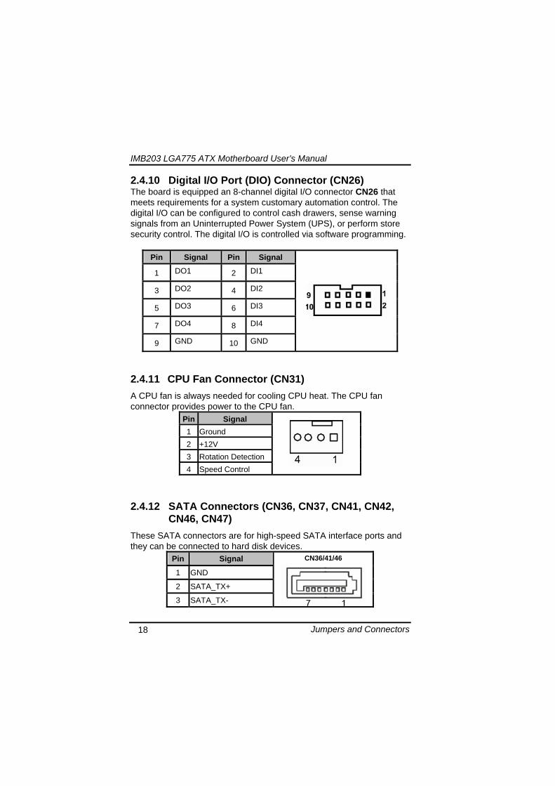
IMB203 LGA775 ATX Motherboard Userrsquos Manual
Jumpers and Connectors 18
2410 Digital IO Port (DIO) Connector (CN26) The board is equipped an 8-channel digital IO connector CN26 that meets requirements for a system customary automation control The digital IO can be configured to control cash drawers sense warning signals from an Uninterrupted Power System (UPS) or perform store security control The digital IO is controlled via software programming
Pin Signal Pin Signal
1 DO1 2 DI1
3 DO2 4 DI2
5 DO3 6 DI3
7 DO4 8 DI4
9 GND 10 GND
2411 CPU Fan Connector (CN31) A CPU fan is always needed for cooling CPU heat The CPU fan connector provides power to the CPU fan
Pin Signal 1 Ground 2 +12V 3 Rotation Detection4 Speed Control
2412 SATA Connectors (CN36 CN37 CN41 CN42
CN46 CN47) These SATA connectors are for high-speed SATA interface ports and they can be connected to hard disk devices
Pin Signal
1 GND
2 SATA_TX+
3 SATA_TX-
CN364146
IMB203 LGA775 ATX Motherboard Userrsquos Manual
Jumpers and Connectors 19
4 GND
5 SATA_RX-
6 SATA_RX+
7 GND
IMB203 LGA775 ATX Motherboard Userrsquos Manual
Jumpers and Connectors 20
2413 ATX Power Connector (CN50) Steady and sufficient power can be supplied to all components on the board by connecting the power connector Please make sure all components and devices are properly installed before connecting the power connector If you use a 24-pin ATX power supply please remove the small cover from the power connector before plugging in the power cord otherwise please do not remove it Pin Signal Pin Signal 1 33V 2 33V
3 GND 4 5V
5 GND 6 5V
7 GND 8 PWR
9 5VSB 10 12V
11 12V 12 33V
13 33V 14 -12V
15 GND 16 PS_ON
17 GND 18 GND
19 GND 20 -5V
21 5V 22 5V
23 5V 24 GND
IMB203 LGA775 ATX Motherboard Userrsquos Manual
Jumpers and Connectors 21
2414 Front Panel Connector (CN52)
Power LED
This 3-pin connector denoted as Pin 1 and Pin 5 connects the system power LED indicator to such a switch on the case Pin 1 is assigned as + and Pin 5 as - The Power LED lights up when the system is powered ON Pin 3 is defined as GND
External Speaker and Internal Buzzer Connector
Pin 2 4 6 and 8 can be connected to the case-mounted speaker unit or internal buzzer While connecting the CPU card to an internal buzzer please short pins 2-4 while connecting to an external speaker you need to set pins 2-4 to Open and connect the speaker cable to pin 8 (+) and pin 2 (-)
ATX Power OnOff Button
This 2-pin connector denoted as Pin 9 and 10 connects the front panelrsquos ATX power button to the CPU card which allows users to control ATX power supply to be power onoff
System Reset Switch
Pin 11 and 12 can be connected to the case-mounted reset switch that reboots your computer instead of turning OFF the power switch It is a better way to reboot your system for a longer life of the systemrsquos power supply
HDD Activity LED
This connection is linked to hard drive activity LED on the control panel LED flashes when HDD is being accessed Pin 13 and 14 connect the hard disk drive to the front panel HDD LED Pin 13 assigned as - and Pin 14 as +
IMB203 LGA775 ATX Motherboard Userrsquos Manual
Jumpers and Connectors 22
MEMO
IMB203 LGA775 ATX Motherboard Userrsquos Manual
Hardware Installation 23
CHAPTER 3 HARDWARE INSTALLATION
Before installing the processor please access Intelreg website for more detailed information httpwwwintelcom
31 Installing the Processor The LGA775 processor socket comes with a cover to protect the processor Please install the processor into the CPU socket step by step as below
Hold the hook (A) of the lever and push it down Pull the lever (B) aside to unlock the cover
IMB203 LGA775 ATX Motherboard Userrsquos Manual
Hardware Installation 24
Remove the plastic cap (E) from the cover
Open the cover (C) you can see the contact
Be careful not to touch the contact (D)
IMB203 LGA775 ATX Motherboard Userrsquos Manual
Hardware Installation 25
Place the CPU down into the socket Be careful not to touch the contact
Hold the edges of the CPU and orientate it as the marked direction (G) down into the socket to match the (H) and (F) locations
IMB203 LGA775 ATX Motherboard Userrsquos Manual
Hardware Installation 26
Slightly push down the cover and hook the lever (I~J) The CPU is completely locked
Orientate the CPU cooling fan to fixing holes on the board
IMB203 LGA775 ATX Motherboard Userrsquos Manual
Hardware Installation 27
Screw the CPU cooling fan onto the board
Make sure the CPU fan is plugged to the CPU fan connector
IMB203 LGA775 ATX Motherboard Userrsquos Manual
Hardware Installation 28
32 Installing the Memory The board supports four 240-pin DDR3 DIMM memory sockets with maximum memory capacity up to 16GB Please follow steps below to install the memory modules 1 Push down latches on each side of the DIMM socket 2 Align the memory module with the socket that notches of
memory module must match the socket keys for a correct installation
3 Install the memory module into the socket and push it firmly down until it is fully seated The socket latches are levered upwards and clipped on to the edges of the DIMM
4 Install any remaining DIMM modules
IMB203 LGA775 ATX Motherboard Userrsquos Manual
Hardware Description 29
CHAPTER 4 HARDWARE DESCRIPTION
41 Microprocessors The IMB203 Series supports Intelreg Coretrade 2 Quad Coretrade 2 Duo processors which make your system operated under Windowsreg XP and Linux environments The system performance depends on the microprocessor Make sure all correct settings are arranged for your installed microprocessor to prevent the CPU from damages
42 BIOS The IMB203 Series uses AMI Plug and Play BIOS with a single 32Mbit SPI Flash
43 System Memory The IMB203 Series supports four 240-pin DDR3 DIMM sockets for a maximum memory of 16GB DDR3 SDRAMs The memory module can come in sizes of 1GB 2GB and 4GB
IMB203 LGA775 ATX Motherboard Userrsquos Manual
Hardware Description 30
44 IO Port Address Map The Intelreg Coretrade 2 Extreme Intelreg Coretrade 2 Quad Coretrade 2 Duo CPUs can communicate via IO ports There are total 1KB port addresses available for assignment to other devices via IO expansion cards
Address Devices 000-01F DMA controller 1
020-02D 024-025 028-029 02C-02D Interrupt controller 1
02E-02F Forwarded to LPC(LPC Super IO ) 030-031 034-035 038-039 03C-03D
Interrupt controller 2
040-043 050-053 TimerCounter (8254) 060 Forwarded to LPC (Microcontroller) 061 NMI
062-066 Forwarded to LPC (Microcontroller) 070-077 Real time clock NMI 080-091 DMA page register
092 Processor IF(Reset Generator) 093-09F DMA page register 0A0-0BF Interrupt controller 2 0C0-0DF DMA controller 2
0F0 Processor IF 0F8-0FF Math processor 170-177 Forward to SATA (SATA Controller) 1F0-1F7 Forward to SATA (SATA Controller)
376 Forward to SATA(SATA Controller) 378-37F Parallel Port (LPT) 380-38F SDLC 2 3A0-3AF SDLC 1 3B0-3BF MDA video card
(to be continued)
IMB203 LGA775 ATX Motherboard Userrsquos Manual
Hardware Description 31
Address Devices 3C0-3CF EGA card 3D0-3DF CGA card
3F6 Forward to SATA(SATA Controller) 3F8-3FF Serial port 1 (COM1) 2F8-2FF Serial port 2 (COM2)
45 Interrupt Controller (IRQ) Map The IMB203 Series is a 100 PC compatible control board It consists of 16 interrupt request lines and four out of them can be programmable The mapping list of the 16 interrupt request lines is shown as the following table
IRQ Parity check error IRQ0 System Timer Output
IRQ1 Keyboard
IRQ2 Interrupt rerouting from IRQ8 through IRQ15
IRQ3 Serial port 2
IRQ4 Serial port 1
IRQ5 PCI Device Share
IRQ7 Parallel port
IRQ8 Real time clock
IRQ9 ACPI Controller
IRQ10 PCI Device Share
IRQ11 PCI Device Share
IRQ12 PS2 Mouse
IRQ13 Math coprocessor
IRQ14 SATA Primary (Legacy Mode)
IRQ15 SATA Secondary (Legacy Mode)
IMB203 LGA775 ATX Motherboard Userrsquos Manual
Hardware Description 32
MEMO
IMB203 LGA775 ATX Motherboard Userrsquos Manual
AMI BIOS Setup Utility 33
CHAPTER 5 AMI BIOS SETUP UTILITY
This chapter provides users with detailed description how to set up basic system configuration through the AMIBIOS8 BIOS setup utility 51 Starting To enter the setup screens follow the steps below 1 Turn on the computer and press the ltDelgt key immediately 2 After you press the ltDeletegt key the main BIOS setup menu
displays You can access the other setup screens from the main BIOS setup menu such as the Chipset and Power menus
52 Navigation Keys The BIOS setuputility uses a key-based navigation system called hot keys Most of the BIOS setup utility hot keys can be used at any time during the setup navigation process These keys include ltF1gt ltF10gt ltEntergt ltESCgt ltArrowgt keys and so on
Note Some of navigation keys differ from one screen to another
IMB203 LGA775 ATX Motherboard Userrsquos Manual
AMI BIOS Setup Utility 34
LeftRight The Left ltArrowgt keys allow you to select a setup screen
UpDown The Up and Down ltArrowgt keys allow you to select a setup screen or sub-screen
+minus PlusMinus The Plus and Minus ltArrowgt keys allow you to change the field value of a particular setup item
Tab The ltTabgt key allows you to select setup fields
F1 The ltF1gt key allows you to display the General Help screen
F10 The ltF10gt key allows you to save any changes you have made and exit Setup Press the ltF10gt key to save your changes
Esc
The ltEscgt key allows you to discard any changes you have made and exit the Setup Press the ltEscgt key to exit the setup without saving your changes
Enter
The ltEntergt key allows you to display or change the setup option listed for a particular setup item The ltEntergt key can also allow you to display the setup sub- screens
IMB203 LGA775 ATX Motherboard Userrsquos Manual
AMI BIOS Setup Utility 35
53 Main Menu When you first enter the Setup Utility you will enter the Main setup screen You can always return to the Main setup screen by selecting the Main tab There are two Main Setup options They are described in this section The Main BIOS Setup screen is shown below
System TimeDate
Use this option to change the system time and date Highlight System Time or System Date using the ltArrowgt keys Enter new values through the keyboard Press the ltTabgt key or the ltArrowgt keys to move between fields The date must be entered in MMDDYY format The time is entered in HHMMSS format
IMB203 LGA775 ATX Motherboard Userrsquos Manual
AMI BIOS Setup Utility 36
54 Advanced Menu The Advanced menu allows users to set configuration of the CPU and other system devices You can select any of the items in the left frame of the screen to go to the sub menus
CPU Configuration IDE Configuration SuperIO Configuration Hardware Health Configuration ACPI Configuration AHCI Configuration Intel iAMT Configuration Intel VT-d Configuration MPS Configuration PCI Express Configuration Trusted Computing USB Configuration
For items marked with ldquo rdquo please press ltEntergt for more options
IMB203 LGA775 ATX Motherboard Userrsquos Manual
AMI BIOS Setup Utility 37
CPU Configuration This screen shows the CPU Configuration and you can change the value of the selected option
Max CPUID Value Limit
You can enable this item to let legacy operating systems boot even without support for CPUs with extended CPU ID functions
Execute-Disable Bit Capability This item helps you enable or disable the No-Execution Page Protection Technology
Core Multi-Processing This feature controls the functionality of the Core Multi-Processing to allow the processor to execute multitasking function
PECI Use this item PECI (Platform Environment Control Interface) to execute the processor temperature monitoring and management
IMB203 LGA775 ATX Motherboard Userrsquos Manual
AMI BIOS Setup Utility 38
Intel (R) C-STATE tech Use this item to enable or disable the C-State technology
IDE Configuration You can use this screen to select options for the IDE Configuration and change the value of the selected option A description of the selected item appears on the right side of the screen For items marked with ldquo rdquo please press ltEntergt for more options
SATA1 Configuration
Use this item to control the onboard SATA controller Here are the options for your selection Compatible Disabled and Enhanced
Configure SATA1 as Use this item to choose the SATA operation mode Here are the options for your selection IDE and AHCI
SATA2 Configuration Use this item to control the onboard SATA controller Here are the options for your selection Enhanced and Disabled
IMB203 LGA775 ATX Motherboard Userrsquos Manual
AMI BIOS Setup Utility 39
PrimarySecondaryThird IDE Master Select one of the hard disk drives to configure IDE devices installed in the system by pressing ltEntergt for more options
Fifth IDE Master Select one of the hard disk drives to configure IDE devices installed in the system by pressing ltEntergt for more options
IMB203 LGA775 ATX Motherboard Userrsquos Manual
AMI BIOS Setup Utility 40
SuperIO Configuration You can use this screen to select options for the SuperIO Configuration and change the value of the selected option A description of the selected item appears on the right side of the screen
Serial Port1 Address
This option specifies the base IO port address and Interrupt Request address of serial port 1 The Optimal setting is 3F8IRQ4 The Fail-Safe default setting is Disabled
Serial Port2 Address This option specifies the base IO port address and Interrupt Request address of serial port 2 The Optimal setting is 2F8IRQ3 The Fail-Safe setting is Disabled
Parallel Port Address This item allows you to determine the IO address for onboard parallel port There are several options for your selection
Parallel Port Mode
IMB203 LGA775 ATX Motherboard Userrsquos Manual
AMI BIOS Setup Utility 41
Select an operating mode for the onboard parallel (printer) port
Parallel Port IRQ Use this item to set up the IRQ for onboard parallel port
Serial Port3 Address This item specifies the base IO port address and Interrupt Request address of serial port 3 The Optimal setting is 3E8IRQ11 The Fail-Safe default setting is Disabled
Serial Port3 IRQ This item specifies the IRQ used by the serial port 3
Serial Port4 Address This item specifies the base IO port address and Interrupt Request address of serial port 4 The Optimal setting is 2E8IRQ10 The Fail-Safe default setting is Disabled
Serial Port4 IRQ This item specifies the IRQ used by the serial port 4
IMB203 LGA775 ATX Motherboard Userrsquos Manual
AMI BIOS Setup Utility 42
Hardware Health Configuration This screen shows the Hardware Health Configuration and a description of the selected item appears on the right side of the screen
HW Health Configuration
This screen displays the temperature of CPU and System Fan Speed Vcore etc
IMB203 LGA775 ATX Motherboard Userrsquos Manual
AMI BIOS Setup Utility 43
ACPI Configuration You can use this screen to select options for the ACPI Configuration and change the value of the selected option A description of the selected item appears on the right side of the screen
General ACPI Configuration
Scroll to this item and press ltEntergt to view the General ACPI Configuration sub menu which contains General ACPI (Advanced Configuration and Power Management Interface) options for your configuration
Advanced ACPI Configuration Scroll to this item and press ltEntergt to view the Advanced ACPI Configuration sub menu which contains Advanced ACPI (Advanced Configuration and Power Management Interface) options for your configuration
Chipset ACPI Configuration Scroll to this item and press ltEntergt to view the Chipset ACPI Configuration sub menu which contains Chipset ACPI (Advanced Configuration and Power Management
IMB203 LGA775 ATX Motherboard Userrsquos Manual
AMI BIOS Setup Utility 44
Interface) options for your configuration AHCI Configuration
You can use this screen to select options for the AHCI Configuration and change the value of the selected option A description of the selected item appears on the right side of the screen
AHCI BIOS Support You can enable or disable this item to control the AHCI function of the SATA controller
IMB203 LGA775 ATX Motherboard Userrsquos Manual
AMI BIOS Setup Utility 45
Intel iAMT Configuration You can use this screen to select options for the Intel iAMT Configuration and change the value of the selected option A description of the selected item appears on the right side of the screen
Intel iAMT Support
You can enable this item to support iAMT (active management technology) function to follow up the procedure for the access to AMI program screen
Unconfigure iAMTME Use this item to unconfigure the iAMTME settings
IMB203 LGA775 ATX Motherboard Userrsquos Manual
AMI BIOS Setup Utility 46
Intel VT-d Configuration You can use this screen to select options for the Intel VT-d Configuration and change the value of the selected option A description of the selected item appears on the right side of the screen
Intel VT-d Virtualization Technology for Directed IO (VT-d) extends Virtualization Technology (VT) roadmap by providing hardware assists for virtualization solution VT-d can help end users improve security and reliability of the systems and also improve performance of IO devices in virtualized environment Here are the options for your selection Disabled and Enabled
IMB203 LGA775 ATX Motherboard Userrsquos Manual
AMI BIOS Setup Utility 47
Remote Access Configuration You can use this screen to select options for the Remote Access Configuration and change the value of the selected option A description of the selected item appears on the right side of the screen
Remote Access Use this item to enable or disable the Remote Access function
IMB203 LGA775 ATX Motherboard Userrsquos Manual
AMI BIOS Setup Utility 48
PCI Express Configuration This screen shows the PCI Express Configuration and you can change its value A description of the selected item appears on the right side of the screen
Active State Power-Management
Use this item to enable or disable the function of Active State Power-Management to provide you with lower power consumption The default setting is Disabled
IMB203 LGA775 ATX Motherboard Userrsquos Manual
AMI BIOS Setup Utility 49
Trusted Computing You can use this screen to select options for the Trusted Computing and change the value of the selected option A description of the selected item appears on the right side of the screen
TCGTPM SUPPORT Use this item to control the Trusted Platform Module (TPM) function
IMB203 LGA775 ATX Motherboard Userrsquos Manual
AMI BIOS Setup Utility 50
USB Configuration You can use this screen to select options for the USB Configuration and change the value of the selected option A description of the selected item appears on the right side of the screen
USB Functions
This item allows you to enable or disable USB functions
Legacy USB Support Use this item to enable or disable support for USB device on legacy operating system The default setting is Enabled
USB 20 Controller Mode Use this item to configure the USB 20 controller The default setting is HiSpeed
BIOS EHCI Hand-Off Enabling this item provide the support for operating systems without an EHCI hand-off feature The default setting is Enabled
IMB203 LGA775 ATX Motherboard Userrsquos Manual
AMI BIOS Setup Utility 51
IMB203 LGA775 ATX Motherboard Userrsquos Manual
AMI BIOS Setup Utility 52
55 PCI PnP Menu The PCI PnP menu allows users to change the advanced settings for PCIPnP devices
Clear NVRAM
Use this item to clear the data in the NVRAM (CMOS) Here are the options for your selection No and Yes
Plug amp Play OS When the setting is No Use this item to configure all the devices in the system When the setting is Yes and if you install a Plug and Play operating system the operating system configures the Plug and Play devices not required for boot The default setting is No
IMB203 LGA775 ATX Motherboard Userrsquos Manual
AMI BIOS Setup Utility 53
PCI Latency Timer This item controls how long a PCI device can hold the PCI bus before another takes over The longer the latency the longer the PCI device can retain control of the bus before handing it over to another PCI device There are several options for your selection
Allocate IRQ to PCI VGA This item allows BIOS to choose an IRQ to assign for the PCI VGA card Here are the options for your selection No and Yes
Palette Snooping Some old graphic controllers need to ldquosnooprdquo on the VGA palette and then map it to their display as a way to provide boot information and VGA compatibility This item allows such snooping to take place Here are the options for your selection Disabled and Enabled
PCI IDE BusMaster This item is a toggle for the built-in driver that allows the onboard IDE controller to perform DMA (Direct Memory Access) transfer Here are the options for your selection Disabled and Enabled
OffBoard PCIISA IDE Card This item is for any other non-onboard PCIISA IDE controller adapter There are several options for your selection
IRQ3457910111415 These items will allow you to assign each system interrupt a type depending on the type of device using the interrupt The option ldquoAvailablerdquo means the IRQ is going to assign automatically Here are the options for your selection Available and Reserved
DMA Channel 013567 These items will allow you to assign each DMA channel a type depending on the type of device using the channel The option ldquoAvailablerdquo means the channel is going to assign automatically Here are the options for your selection Available and Reserved
IMB203 LGA775 ATX Motherboard Userrsquos Manual
AMI BIOS Setup Utility 54
56 Boot Menu The Boot menu allows users to change boot options of the system You can select any of the items in the left frame of the screen to go to the sub menus
Boot Settings Configuration Boot Device Priority Removable Drives
For items marked with ldquo rdquo please press ltEntergt for more options
IMB203 LGA775 ATX Motherboard Userrsquos Manual
AMI BIOS Setup Utility 55
Boot Settings Configuration
Quick Boot
Enabling this item lets the BIOS skip some power on self tests (POST) The default setting is Enabled
AddOn ROM Display Mode This item selects the display mode for option ROM The default setting is Force BIOS
Boot Num-Lock Use this item to select the power-on state for the NumLock The default setting is On
PS2 Mouse Support This item determines if the BIOS should reserve IRQ12 for the PS2 mouse or allow other devices to make use of this IRQ Here are the options for your selection Auto Enabled and Disabled
Wait For lsquoF1rsquo Of Error If this item is enabled the system waits for the F1 key to be pressed when error occurs The default setting is Enabled
Hit lsquoDELrsquo Message Display If this item is enabled the system displays the message
IMB203 LGA775 ATX Motherboard Userrsquos Manual
AMI BIOS Setup Utility 56
ldquoPress DEL to run Setuprdquo during POST The default setting is Enabled
Interrupt 19 Capture If this item is enabled this function makes the option ROMs to trap Interrupt 19 The default setting is Disabled
Boot Device Priority The Boot Device Priority screen specifies the boot device priority sequence from the available devices
IMB203 LGA775 ATX Motherboard Userrsquos Manual
AMI BIOS Setup Utility 57
Removable Drives Use this screen to view the removable drives in the system The BIOS will attempt to arrange the removable drive boot sequence automatically You can also change the booting sequence
IMB203 LGA775 ATX Motherboard Userrsquos Manual
AMI BIOS Setup Utility 58
57 Security Menu The Security menu allows users to change the security settings for the system
Supervisor Password
This item indicates whether a supervisor password has been set If the password has been installed Installed displays If not Not Installed displays
User Password This item indicates whether a user password has been set If the password has been installed Installed displays If not Not Installed displays
Change Supervisor Password Select this option and press ltEntergt to access the sub menu You can use the sub menu to change the supervisor password
Change User Password Select this option and press ltEntergt to access the sub menu You can use the sub menu to change the user password
IMB203 LGA775 ATX Motherboard Userrsquos Manual
AMI BIOS Setup Utility 59
58 Chipset Menu The Chipset menu allows users to change the advanced chipset settings You can select any of the items in the left frame of the screen to go to the sub menus
North Bridge Configuration South Bridge Configuration ME Subsystem Configuration
For items marked with ldquo rdquo please press ltEntergt for more options
IMB203 LGA775 ATX Motherboard Userrsquos Manual
AMI BIOS Setup Utility 60
North Bridge Configuration
Memory Remap Feature
Use this item to enable or disable the remapping of the overlapped PCI memory above the total physical memory Only 64-bit OS supports this function
DRAM Frequency This item allows you to control the Memory Clock
Configure DRAM Timing by SPD This item can enable or disable DRAM timing by SPD (Serial Presence Detect) device which is a small EEPROM chip on the memory module containing important information about the module speed size addressing mode and various parameters
Memory Hole You can reserve this area of system memory for ISA adapter ROM When this area is reserved it cannot be cached Check the user information of peripherals that need to use this area o f system memory for the memory requirements Here are the options Disabled and 15M-16M
IMB203 LGA775 ATX Motherboard Userrsquos Manual
AMI BIOS Setup Utility 61
Initiate Graphic Adapter When using multiple graphics cards this item can select which graphics controller to be the primary display device during boot
IGD Graphics Mode Select This item allows you to select the amount of system memory used by the internal graphics device
PEG Port ConfigurationPEG Port This item is a toggle to enable or disable the PCI Express port Here are the options for your selection Auto and Disabled
Video Function Configuration Press ltEntergt for the sub-menu for setting up video function
IMB203 LGA775 ATX Motherboard Userrsquos Manual
AMI BIOS Setup Utility 62
South Bridge Configuration
GbE Wake Up From S5 This item specifies whether the system will be awakened from the S5 power
HDA Controller This item allows you to enable or disable the HD audio support
Restore on AC Power Loss This item can control how the PC will behave once power is restored following a power outage or other unexpected shutdown
PCIE Port Configuration This item allows you to set or disable the PCI Express Ports
IMB203 LGA775 ATX Motherboard Userrsquos Manual
AMI BIOS Setup Utility 63
ME Subsystem Configuration
It is strongly recommended that you do not modify these options unless you are an advanced user
IMB203 LGA775 ATX Motherboard Userrsquos Manual
AMI BIOS Setup Utility 64
59 Exit Menu The Exit menu allows users to load your system configuration with optimal or failsafe default values
Save Changes and Exit
When you have completed the system configuration changes select this option to leave Setup and reboot the computer so the new system configuration parameters can take effect Select Save Changes and Exit from the Exit menu and press ltEntergt Select Ok to save changes and exit
Discard Changes and Exit Select this option to quit Setup without making any permanent changes to the system configuration Select Discard Changes and Exit from the Exit menu and press ltEntergt Select Ok to discard changes and exit
Load Optimal Defaults It automatically sets all Setup options to a complete set of default settings when you select this option The Optimal settings are designed for maximum system performance but may not work best for all computer applications In particular do not use the Optimal Setup options if your
IMB203 LGA775 ATX Motherboard Userrsquos Manual
AMI BIOS Setup Utility 65
computer is experiencing system configuration problems Select Load Optimal Defaults from the Exit menu and press ltEntergt
Load Fail-Safe Defaults It automatically sets all Setup options to a complete set of default settings when you select this option The Fail-Safe settings are designed for maximum system stability but not maximum performance Select the Fail-Safe Setup options if your computer is experiencing system configuration problems Select Load Fail-Safe Defaults from the Exit menu and press ltEntergt Select Ok to load Fail-Safe defaults
IMB203 LGA775 ATX Motherboard Userrsquos Manual
AMI BIOS Setup Utility 66
MEMO
IMB203 LGA775 ATX Motherboard Userrsquos Manual
Installation of Drivers 67
CHPATER 6 INSTALLATION OF DRIVERS
The device drivers are located on the Product Information CD-ROM that comes with the IMB203 Series package The auto-run function of drivers will guide you to install the utilities and device drivers under a Windows system You can follow the onscreen instructions to install these devices
Chipse VGA LAN Audio iAMT MEI
61 Installing Chipset Driver 1 Run the SETUPEXE program from the driver directory in
your driver CD Click ldquoNextrdquo to next step
IMB203 LGA775 ATX Motherboard Userrsquos Manual
Installation of Drivers 68
2 An Intelreg License Agreement appears to show you the important information Click ldquoYesrdquo to next step
3 Refer to the Readme file below to view the system requirements and installation information
IMB203 LGA775 ATX Motherboard Userrsquos Manual
Installation of Drivers 69
3-1 Please wait while running the following setup operations
3-2 Please wait while running the following setup operations
IMB203 LGA775 ATX Motherboard Userrsquos Manual
Installation of Drivers 70
4 Click ldquoFinishrdquo to complete the setup process
5 You will be asked to reboot your computer when the installation is completed Please click ldquoYes I want to restart my computer nowrdquo if you donrsquot need to install any other drivers Otherwise please click ldquoNo I will restart my computer laterrdquo and go on next step
IMB203 LGA775 ATX Motherboard Userrsquos Manual
Installation of Drivers 71
62 Installing VGA Driver 1 Run the SETUPEXE program from the driver directory in
your driver CD Click ldquoNextrdquo to next step
2 An Intelreg License Agreement appears to show you the
important information Click ldquoYesrdquo to next step
IMB203 LGA775 ATX Motherboard Userrsquos Manual
Installation of Drivers 72
3 The message of Readme File Information appears to show you the system requirements and installation information Please click ldquoNextrdquo
4 Please wait while running the following setup operations
When this message appears please click ldquoNextrdquo
IMB203 LGA775 ATX Motherboard Userrsquos Manual
Installation of Drivers 73
5 Click ldquoFinishrdquo to complete the setup process
6 You will be asked to reboot your computer when the installation is completed Please click ldquoYes I want to restart my computer nowrdquo if you donrsquot need to install any other drivers Otherwise please click ldquoNo I will restart my computer laterrdquo and click ldquoFinishrdquo to complete the installation
IMB203 LGA775 ATX Motherboard Userrsquos Manual
Installation of Drivers 74
63 Installing LAN Driver
11 Run the InstallShield Wizard for Network Connections from
the driver directory in your driver CD Click ldquoNextrdquo to next step
IMB203 LGA775 ATX Motherboard Userrsquos Manual
Installation of Drivers 75
12 An Intelreg License Agreement appears to show you the important information Click ldquoYesrdquo to next step
13 A Setup Options window appears that you can select the
program features you want to install
IMB203 LGA775 ATX Motherboard Userrsquos Manual
Installation of Drivers 76
2 Click ldquoInstallrdquo to start the installation
3 Please wait while running the following installation operation
IMB203 LGA775 ATX Motherboard Userrsquos Manual
Installation of Drivers 77
4 Click ldquoFinishrdquo to complete the installation
Note The Driver item [Wake on Directed Packet] default is Enabled under Windows Vista
格式化 字型 (符號) Arial
格式化 字型 (符號) Arial
格式化 字型 斜體 字型色彩 黑色 (符號) Arial 非加寬 緊縮
格式化 字型 斜體 字型色彩 黑色 (符號) Arial 非加寬 緊縮
格式化 字型 (符號) Arial 非加寬 緊縮
IMB203 LGA775 ATX Motherboard Userrsquos Manual
Installation of Drivers 78
64 Installing AUDIO Driver 1 Run the InstallShield Wizard for Realtek High Definition
Audio Driver from the driver directory in your driver CD Click ldquoNextrdquo to next step
IMB203 LGA775 ATX Motherboard Userrsquos Manual
Installation of Drivers 79
2 Click ldquoInstallrdquo to start the installation and wait while running the installation operation
3 Click ldquoFinishrdquo to complete the installation
IMB203 LGA775 ATX Motherboard Userrsquos Manual
Installation of Drivers 80
65 Installing iAMT (Active Management Technology) Driver
Note You must download and properly install the required NET version 35 provided from a separate downloading of the actual FimwareTools kit releases posted on VIP prior to loading the MEILMS Driver stack
651 LMS_SOL Setup
1 Run the setup program to install Intelreg Active Management Technology onto your computer It is strongly recommended that you exit all programs before continuing Click ldquoNextrdquo to next step
格式化 字型 (符號) Arial
格式化 字型 (符號) Arial 非加寬 緊縮
IMB203 LGA775 ATX Motherboard Userrsquos Manual
Installation of Drivers 81
2 An Intelreg license agreement appears that you need to continue the setup program by clicking ldquoYesrdquo to accept the terms
IMB203 LGA775 ATX Motherboard Userrsquos Manual
Installation of Drivers 82
3 Refer to the Readme file below to view the system requirements and installation information Click ldquoNextrdquo to next setup
4 Please wait while running the following installation operation
IMB203 LGA775 ATX Motherboard Userrsquos Manual
Installation of Drivers 83
5 Click ldquoFinishrdquo to complete the installation
IMB203 LGA775 ATX Motherboard Userrsquos Manual
Installation of Drivers 84
652 LMS_SOL_IS Setup
1 Run the setup program to install Intelreg Active Management Technology onto your computer It is strongly recommended that you exit all programs before continuing Click ldquoNextrdquo to next step
IMB203 LGA775 ATX Motherboard Userrsquos Manual
Installation of Drivers 85
2 An Intelreg license agreement appears that you need to continue the setup program by clicking ldquoYesrdquo to accept the terms
IMB203 LGA775 ATX Motherboard Userrsquos Manual
Installation of Drivers 86
3 Refer to the Readme file below to view the system requirements and installation information Click ldquoNextrdquo to next setup
4 Please wait while running the following installation operation
IMB203 LGA775 ATX Motherboard Userrsquos Manual
Installation of Drivers 87
5 Click ldquoFinishrdquo to complete the installation
IMB203 LGA775 ATX Motherboard Userrsquos Manual
Installation of Drivers 88
66 Installing MEI (Management Engine Interface) Driver
Note You must download and properly install the required NET version 35 provided from a separate downloading of the actual FimwareTools kit releases posted on VIP prior to loading the MEILMS Driver stack
1 Run the setup program to install Intelreg Management Engine
Interface onto your computer It is strongly recommended that you exit all programs before continuing Click ldquoNextrdquo to next step
格式化 字型 (符號) Arial
格式化 字型 (符號) Arial 非加寬 緊縮
IMB203 LGA775 ATX Motherboard Userrsquos Manual
Installation of Drivers 89
2 An Intelreg license agreement appears that you need to continue the setup program by clicking ldquoYesrdquo to accept the terms
IMB203 LGA775 ATX Motherboard Userrsquos Manual
Installation of Drivers 90
3 Refer to the Readme file below to view the system requirements and installation information Click ldquoNextrdquo to next setup
4 Please wait while running the following installation operation
IMB203 LGA775 ATX Motherboard Userrsquos Manual
Installation of Drivers 91
5 Click ldquoFinishrdquo to complete the installation
IMB203 LGA775 ATX Motherboard Userrsquos Manual
Installation of Drivers 92
MEMO
IMB203 LGA775 ATX Motherboard Userrsquos Manual
Watchdog Timer 93
APPENDIX A WATCHDOG TIMER
Watchdog Timer Setting After the system stops working for a while it can be auto-reset by the Watchdog Timer The integrated Watchdog Timer can be set up in the system reset mode by program
Using the Watchdog Function Start darr Un-Lock WDT O 2E 87 Un-lock super IO
O 2E 87 Un-lock super IO darr Set WDT Function O 2E 2D O 2F 20 Select Logic device O 2E 07 O 2F 08 darr Activate WDT O 2E 30
O 2F 01 Set Second or Minute O 2E F5
O 2F N N=00 or 08(See below table) darr Set base timer O 2E F6
O 2F M=000102hellipFF(Hex) Value=0 to 255 darr WDT counting
re-set timer O 2E F6
O 2F M M=000102hellipFF(See below table) darr
格式化
格式化 項目符號及編號
格式化 項目符號及編號
格式化 字型 8 點 字型色彩黑色
格式化 字型 8 點 字型色彩黑色
格式化 定位點 1257 字元左 + 不在 1012 字元 + 1386字元
格式化 字型 8 點 字型色彩黑色
格式化 定位點 1257 字元左 + 不在 134 字元 + 1362字元
格式化 字型色彩 黑色
格式化 字型色彩 黑色
刪除
IMB203 LGA775 ATX Motherboard Userrsquos Manual
Watchdog Timer 94
IF No re-set timer WDT time-out generate RESET IF to disable WDT O 2E 30
O 2F 00 Can be disable at any time
N=00
M= 00h Time-out Disable 01h Time-out occurs after 1 second 02h Time-out occurs after 2 second 03h Time-out occurs after 3 second helliphelliphelliphelliphelliphelliphelliphelliphellip FFh Time-out occurs after 255 second
N=08
M= 00h Time-out Disable 01h Time-out occurs after 1 minute 02h Time-out occurs after 2 minutes 03h Time-out occurs after 3 minutes helliphelliphelliphelliphelliphelliphelliphelliphellip
FFh Time-out occurs after 255 minutes
格式化 字型色彩 黑色
格式化 字型色彩 黑色
IMB203 LGA775 ATX Motherboard Userrsquos Manual
PCI IRQ Routing 95
APPENDIX B PCI IRQ ROUTING
PICMG PCI IRQ Routing
Device ID Slot Int
PCI Slot 0 31 0 BCDA PCI Slot 1 30 1 CDAB PCI Slot 2 29 2 DABC PCI Slot 3 28 3 ABCD
IMB203 LGA775 ATX Motherboard Userrsquos Manual
PCI IRQ Routing 96
MEMO
IMB203 LGA775 ATX Motherboard Userrsquos Manual
Configuring SATA for RAID Function 97
APPENDIX C CONFIGURING SATA FOR RAID
FUNCTION
Configuring SATA Hard Drive(s) for RAID Function (Controller IntelregICH10DODO DH only) Please follow up the steps below to configure SATA hard drive(s) (1) Install SATA hard drive(s) in your system (2) Enter the BIOS Setup to configure SATA controller mode and boot
sequence (3) Configure RAID by the RAID BIOS (4) Install the SATA controller driver during the OS installation Before you begin the SATA configuration please prepare (a) Two SATA hard drives (to ensure optimal performance it is
recommended that you use two hard drives with identical model and capacity) If you do not want to create RAID with the SATA controller you may prepare only one hard drive
(b) An empty formatted floppy disk (c) Windows XP setup disk (1) Installing SATA hard drive(s) in your system
Connect one end of the SATA signal cable to the rear of the SATA hard drive and the other end to available SATA port(s) on the board Then connect the power connector of power supply to the hard drive
(2) Configuring SATA controller mode and boot sequence by the BIOS Setup You have to make sure whether the SATA controller is configured correctly by system BIOS Setup and set up BIOS boot sequence for the SATA hard drive(s)
IMB203 LGA775 ATX Motherboard Userrsquos Manual
Configuring SATA for RAID Function 98
(2)-1-1 Turn on your system and then press the Del button to enter BIOS Setup during running POST (Power-On Self Test) If you want to create RAID just go to the Advanced Settings menuIDE configuration select the Configure SATA1 as and press ltEntergt for more options
IMB203 LGA775 ATX Motherboard Userrsquos Manual
Configuring SATA for RAID Function 99
(2)-1-2 A list of options appears please select RAID
IMB203 LGA775 ATX Motherboard Userrsquos Manual
Configuring SATA for RAID Function 100
(2)-2 Set CDROM for First Boot Device under the Boot Settings menu to boot CD-ROM after system restarts
(2)-3 Save and exit the BIOS Setup
IMB203 LGA775 ATX Motherboard Userrsquos Manual
Configuring SATA for RAID Function 101
(3) Configuring RAID by the RAID BIOS Enter the RAID BIOS setup utility to configure a RAID array Skip this step and proceed to Section 4 if you do not want to create a RAID (3)-1 After the POST memory testing and before the operating
system booting a message Press ltCtrl-Igt to enter Configuration Utility shows up accordingly press ltCTRL+ Igt to enter the RAID BIOS setup utility
(3)-2 After you press ltCTRL+ Igt the Create RAID Volume screen will appear If you want to create a RAID array select the Create RAID Volume option in the Main Menu and press ENTER
IMB203 LGA775 ATX Motherboard Userrsquos Manual
Configuring SATA for RAID Function 102
(3)-3-1 After entering the CREATE VOLUME MENU screen you can type the disk array name with 1~16 letters (letters cannot be special characters) in the item ldquoNamerdquo
(3)-3-2 When finished press ENTER to select a RAID level There are three RAID levels RAID0 RAID1 and RAID5 amp RAID10 Select a RAID level and press ENTER
IMB203 LGA775 ATX Motherboard Userrsquos Manual
Configuring SATA for RAID Function 103
(3)-4 Set the stripe block size The KB is the standard unit of stripe block size The stripe block size can be 4KB to 128KB After the setting press ENTER for the array capacity
(3)-5 After setting all the items on the menu select Create Volume
and press ENTER to start creating the RAID array
IMB203 LGA775 ATX Motherboard Userrsquos Manual
Configuring SATA for RAID Function 104
(3)-6 When prompting the confirmation press ldquoYldquo to create this volume or ldquoNldquo to cancel the creation
After the creation is completed you can see detailed information about the RAID Array in the DISKVOLUME INFORMATION section including RAID mode disk block size disk name and disk capacity etc
IMB203 LGA775 ATX Motherboard Userrsquos Manual
Configuring SATA for RAID Function 105
Delete RAID Volume If you want to delete a RAID volume select the Delete RAID Volume option in Main Menu Press ENTER and follow on-screen instructions
Please press [ESC] to exit the RAID BIOS utility Now you can proceed to install a SATA driver controller and the operating system
IMB203 LGA775 ATX Motherboard Userrsquos Manual
Configuring SATA for RAID Function 106
(4) Making a SATA Driver Disk To install the operating system onto a serial ATA hard disk successfully you need to install the SATA controller driver during the OS installation Without the driver the hard disk may not be recognized during the Windows setup process First of all please format a blank floppy disk Secondly follow up these steps below to produce a SATA driver disk Users can insert the Driver CD and the formatted blank floppy disk in another system And then please copy all of file of the f6flpy32 folder in the Driver CD to a floppy disk Note Please copy all of file of the f6flpy64 folder if installing 64-bit
Windows Operating System
IMB203 LGA775 ATX Motherboard Userrsquos Manual
Configuring SATA for RAID Function 107
(5) Installing the SATA controller driver during the OS installation Now the SATA driver disk is ready and BIOS settings configured you can proceed to install Windows 2000XP onto your SATA hard drive using the SATA driver Here is an example for Windows XP installation (5)-1 Restart your system to boot the Windows 2000XP Setup disk
and press F6 button as soon as you see the message Press F6 if you need to install a 3rd party SCSI or RAID driver After pressing the F6 button there will be a few moments for some files being loaded before next screen appears
IMB203 LGA775 ATX Motherboard Userrsquos Manual
Configuring SATA for RAID Function 108
(5)-2 When you see the screen below insert the floppy disk containing the SATA driver and press ldquoSrdquo
(5)-3 If the Setup correctly recognizes the driver of the floppy disk
a controller menu will appear below Use the ARROW keys to select Intel(R) ICH8RICH9RICH10RDO SATA RAID Controller and press ENTER Then it will begin to load the SATA driver from the floppy disk
IMB203 LGA775 ATX Motherboard Userrsquos Manual
Configuring SATA for RAID Function 109
Note If a message on the screen saying that one or some file(s) cannot be found please check the floppy disk or copy the correct SATA driver again from the driver CD
IMB203 LGA775 ATX Motherboard Userrsquos Manual
Configuring SATA for RAID Function 110
MEMO
IMB203 LGA775 ATX Motherboard Userrsquos Manual
iAMT Settings 111
APPENDIX D iAMT SETTINGS
The Intelreg Active Management Technology (Intelreg iAMT) has decreased a major barrier to IT efficiency that uses built-in platform capabilities and popular third-party management and security applications to allow IT a better discovering healing and protection their networked computing assets In order to utilize Intel iAMT you must enter the ME BIOS (CTRL + P during system startup) change the ME BIOS password and then select ldquoIntelreg iAMTrdquo as the manageability feature
D1 Entering MEBx 1 You must go to BIOS TO start iAMT function 2 Exit from BIOS after starting iAMT and press Ctrl+P to enter MEBx Setting
It is better to press Ctrl+P before the screen popping out
格式化
IMB203 LGA775 ATX Motherboard Userrsquos Manual
iAMT Settings 112
D2 Set amp Change Password 1 You will be asked to set a password when first log in The default
password is lsquoadminrsquo
2 You will be asked to change the password before setting ME
Change Password
IMB203 LGA775 ATX Motherboard Userrsquos Manual
iAMT Settings 113
3 You must confirm your new password while revising (as Remark 1)
Remark 1 The new password must contain (example 11qqQQ) (default value)
Eight characters
One upper case
One lower case
One number
One special symbol such as $ or
( excepted)
Underline ( _ ) and space are valid characters for password but they wonrsquot make higher complexity
IMB203 LGA775 ATX Motherboard Userrsquos Manual
iAMT Settings 114
D3 Intelreg iAMT Settings 1 Select Intelreg iAMT Configuration and press ltENTERgt
2 Key in the Host Name If Intelreg iAMT set to lsquoDHCPlsquo the Host name must be identical to the operating system mechanic
IMB203 LGA775 ATX Motherboard Userrsquos Manual
iAMT Settings 115
3 Select TCPIP to get into Network interface and set it to lsquoENABLEDrsquo into DHCP Mode and set it to lsquoDISABLEDrsquo (as Remark 2) into Domain name and set the Intel Management Engine domain name such as lsquoAMTintelcomrsquo
(3-1)
(3-2)
IMB203 LGA775 ATX Motherboard Userrsquos Manual
iAMT Settings 116
Remark 2 DHCP Mode lsquoDISABLEDlsquo if DHCP Mode is disabled you can make the following settings
IP address
Subnet mask
IMB203 LGA775 ATX Motherboard Userrsquos Manual
iAMT Settings 117
Default Gateway address
Preferred DNS address
IMB203 LGA775 ATX Motherboard Userrsquos Manual
iAMT Settings 118
Alternate DNS address
Domain name
4 Exit from MEBx after completing the iAMT settings
IMB203 LGA775 ATX Motherboard Userrsquos Manual
iAMT Settings 119
D4 iAMT Web Console 1 From a web browser please type http(IP ADDRESS)16992
which connects to iAMT Web Example http1014021416992
2 To log on you will be required to type in username and password
for access to the Web
USER admin (default value)
PASS (MEBx password)
IMB203 LGA775 ATX Motherboard Userrsquos Manual
iAMT Settings 120
3 Enter the iAMT Web
4 Click Remote Control and select commands on the right side
IMB203 LGA775 ATX Motherboard Userrsquos Manual
iAMT Settings 121
5 When you have finished using the iAMT Web console close the Web browser
IMB203 LGA775 ATX Motherboard Userrsquos Manual
iAMT Settings 122
MEMO
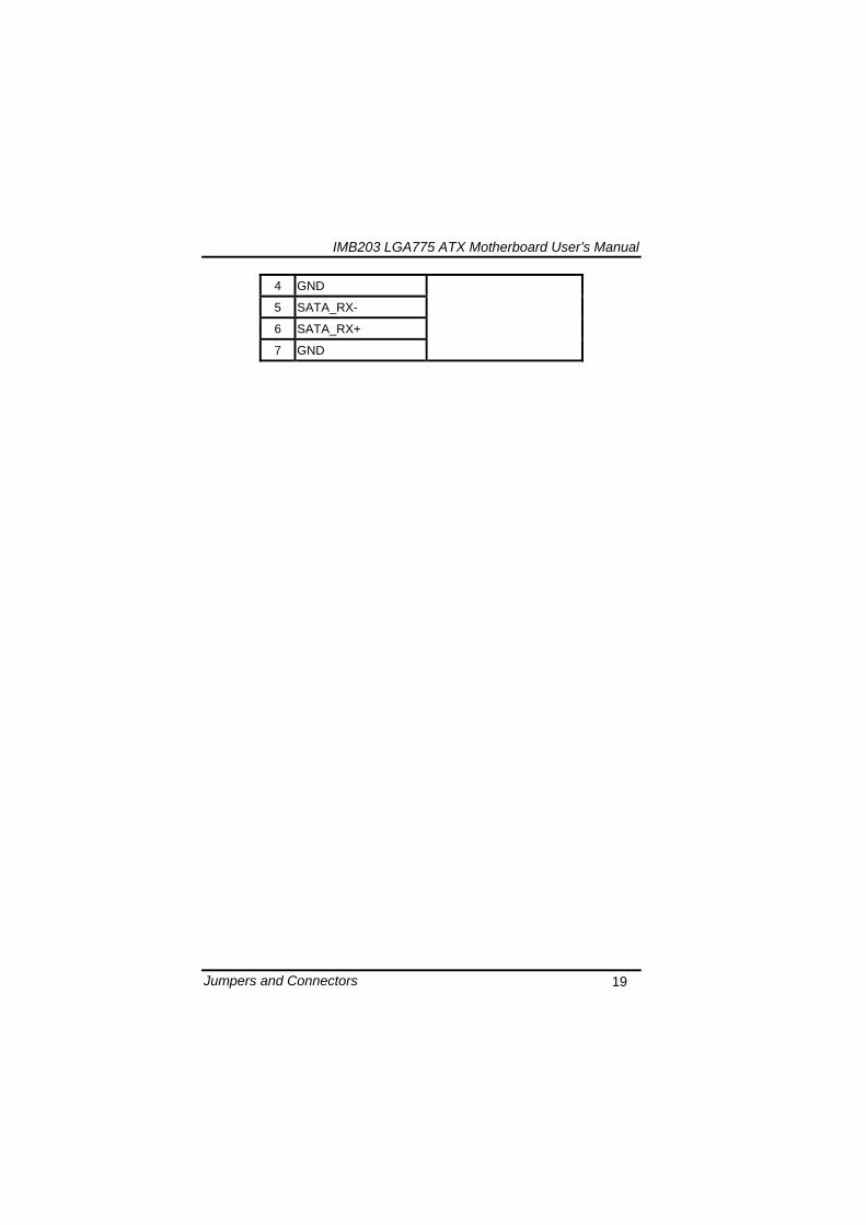
IMB203 LGA775 ATX Motherboard Userrsquos Manual
Jumpers and Connectors 19
4 GND
5 SATA_RX-
6 SATA_RX+
7 GND
IMB203 LGA775 ATX Motherboard Userrsquos Manual
Jumpers and Connectors 20
2413 ATX Power Connector (CN50) Steady and sufficient power can be supplied to all components on the board by connecting the power connector Please make sure all components and devices are properly installed before connecting the power connector If you use a 24-pin ATX power supply please remove the small cover from the power connector before plugging in the power cord otherwise please do not remove it Pin Signal Pin Signal 1 33V 2 33V
3 GND 4 5V
5 GND 6 5V
7 GND 8 PWR
9 5VSB 10 12V
11 12V 12 33V
13 33V 14 -12V
15 GND 16 PS_ON
17 GND 18 GND
19 GND 20 -5V
21 5V 22 5V
23 5V 24 GND
IMB203 LGA775 ATX Motherboard Userrsquos Manual
Jumpers and Connectors 21
2414 Front Panel Connector (CN52)
Power LED
This 3-pin connector denoted as Pin 1 and Pin 5 connects the system power LED indicator to such a switch on the case Pin 1 is assigned as + and Pin 5 as - The Power LED lights up when the system is powered ON Pin 3 is defined as GND
External Speaker and Internal Buzzer Connector
Pin 2 4 6 and 8 can be connected to the case-mounted speaker unit or internal buzzer While connecting the CPU card to an internal buzzer please short pins 2-4 while connecting to an external speaker you need to set pins 2-4 to Open and connect the speaker cable to pin 8 (+) and pin 2 (-)
ATX Power OnOff Button
This 2-pin connector denoted as Pin 9 and 10 connects the front panelrsquos ATX power button to the CPU card which allows users to control ATX power supply to be power onoff
System Reset Switch
Pin 11 and 12 can be connected to the case-mounted reset switch that reboots your computer instead of turning OFF the power switch It is a better way to reboot your system for a longer life of the systemrsquos power supply
HDD Activity LED
This connection is linked to hard drive activity LED on the control panel LED flashes when HDD is being accessed Pin 13 and 14 connect the hard disk drive to the front panel HDD LED Pin 13 assigned as - and Pin 14 as +
IMB203 LGA775 ATX Motherboard Userrsquos Manual
Jumpers and Connectors 22
MEMO
IMB203 LGA775 ATX Motherboard Userrsquos Manual
Hardware Installation 23
CHAPTER 3 HARDWARE INSTALLATION
Before installing the processor please access Intelreg website for more detailed information httpwwwintelcom
31 Installing the Processor The LGA775 processor socket comes with a cover to protect the processor Please install the processor into the CPU socket step by step as below
Hold the hook (A) of the lever and push it down Pull the lever (B) aside to unlock the cover
IMB203 LGA775 ATX Motherboard Userrsquos Manual
Hardware Installation 24
Remove the plastic cap (E) from the cover
Open the cover (C) you can see the contact
Be careful not to touch the contact (D)
IMB203 LGA775 ATX Motherboard Userrsquos Manual
Hardware Installation 25
Place the CPU down into the socket Be careful not to touch the contact
Hold the edges of the CPU and orientate it as the marked direction (G) down into the socket to match the (H) and (F) locations
IMB203 LGA775 ATX Motherboard Userrsquos Manual
Hardware Installation 26
Slightly push down the cover and hook the lever (I~J) The CPU is completely locked
Orientate the CPU cooling fan to fixing holes on the board
IMB203 LGA775 ATX Motherboard Userrsquos Manual
Hardware Installation 27
Screw the CPU cooling fan onto the board
Make sure the CPU fan is plugged to the CPU fan connector
IMB203 LGA775 ATX Motherboard Userrsquos Manual
Hardware Installation 28
32 Installing the Memory The board supports four 240-pin DDR3 DIMM memory sockets with maximum memory capacity up to 16GB Please follow steps below to install the memory modules 1 Push down latches on each side of the DIMM socket 2 Align the memory module with the socket that notches of
memory module must match the socket keys for a correct installation
3 Install the memory module into the socket and push it firmly down until it is fully seated The socket latches are levered upwards and clipped on to the edges of the DIMM
4 Install any remaining DIMM modules
IMB203 LGA775 ATX Motherboard Userrsquos Manual
Hardware Description 29
CHAPTER 4 HARDWARE DESCRIPTION
41 Microprocessors The IMB203 Series supports Intelreg Coretrade 2 Quad Coretrade 2 Duo processors which make your system operated under Windowsreg XP and Linux environments The system performance depends on the microprocessor Make sure all correct settings are arranged for your installed microprocessor to prevent the CPU from damages
42 BIOS The IMB203 Series uses AMI Plug and Play BIOS with a single 32Mbit SPI Flash
43 System Memory The IMB203 Series supports four 240-pin DDR3 DIMM sockets for a maximum memory of 16GB DDR3 SDRAMs The memory module can come in sizes of 1GB 2GB and 4GB
IMB203 LGA775 ATX Motherboard Userrsquos Manual
Hardware Description 30
44 IO Port Address Map The Intelreg Coretrade 2 Extreme Intelreg Coretrade 2 Quad Coretrade 2 Duo CPUs can communicate via IO ports There are total 1KB port addresses available for assignment to other devices via IO expansion cards
Address Devices 000-01F DMA controller 1
020-02D 024-025 028-029 02C-02D Interrupt controller 1
02E-02F Forwarded to LPC(LPC Super IO ) 030-031 034-035 038-039 03C-03D
Interrupt controller 2
040-043 050-053 TimerCounter (8254) 060 Forwarded to LPC (Microcontroller) 061 NMI
062-066 Forwarded to LPC (Microcontroller) 070-077 Real time clock NMI 080-091 DMA page register
092 Processor IF(Reset Generator) 093-09F DMA page register 0A0-0BF Interrupt controller 2 0C0-0DF DMA controller 2
0F0 Processor IF 0F8-0FF Math processor 170-177 Forward to SATA (SATA Controller) 1F0-1F7 Forward to SATA (SATA Controller)
376 Forward to SATA(SATA Controller) 378-37F Parallel Port (LPT) 380-38F SDLC 2 3A0-3AF SDLC 1 3B0-3BF MDA video card
(to be continued)
IMB203 LGA775 ATX Motherboard Userrsquos Manual
Hardware Description 31
Address Devices 3C0-3CF EGA card 3D0-3DF CGA card
3F6 Forward to SATA(SATA Controller) 3F8-3FF Serial port 1 (COM1) 2F8-2FF Serial port 2 (COM2)
45 Interrupt Controller (IRQ) Map The IMB203 Series is a 100 PC compatible control board It consists of 16 interrupt request lines and four out of them can be programmable The mapping list of the 16 interrupt request lines is shown as the following table
IRQ Parity check error IRQ0 System Timer Output
IRQ1 Keyboard
IRQ2 Interrupt rerouting from IRQ8 through IRQ15
IRQ3 Serial port 2
IRQ4 Serial port 1
IRQ5 PCI Device Share
IRQ7 Parallel port
IRQ8 Real time clock
IRQ9 ACPI Controller
IRQ10 PCI Device Share
IRQ11 PCI Device Share
IRQ12 PS2 Mouse
IRQ13 Math coprocessor
IRQ14 SATA Primary (Legacy Mode)
IRQ15 SATA Secondary (Legacy Mode)
IMB203 LGA775 ATX Motherboard Userrsquos Manual
Hardware Description 32
MEMO
IMB203 LGA775 ATX Motherboard Userrsquos Manual
AMI BIOS Setup Utility 33
CHAPTER 5 AMI BIOS SETUP UTILITY
This chapter provides users with detailed description how to set up basic system configuration through the AMIBIOS8 BIOS setup utility 51 Starting To enter the setup screens follow the steps below 1 Turn on the computer and press the ltDelgt key immediately 2 After you press the ltDeletegt key the main BIOS setup menu
displays You can access the other setup screens from the main BIOS setup menu such as the Chipset and Power menus
52 Navigation Keys The BIOS setuputility uses a key-based navigation system called hot keys Most of the BIOS setup utility hot keys can be used at any time during the setup navigation process These keys include ltF1gt ltF10gt ltEntergt ltESCgt ltArrowgt keys and so on
Note Some of navigation keys differ from one screen to another
IMB203 LGA775 ATX Motherboard Userrsquos Manual
AMI BIOS Setup Utility 34
LeftRight The Left ltArrowgt keys allow you to select a setup screen
UpDown The Up and Down ltArrowgt keys allow you to select a setup screen or sub-screen
+minus PlusMinus The Plus and Minus ltArrowgt keys allow you to change the field value of a particular setup item
Tab The ltTabgt key allows you to select setup fields
F1 The ltF1gt key allows you to display the General Help screen
F10 The ltF10gt key allows you to save any changes you have made and exit Setup Press the ltF10gt key to save your changes
Esc
The ltEscgt key allows you to discard any changes you have made and exit the Setup Press the ltEscgt key to exit the setup without saving your changes
Enter
The ltEntergt key allows you to display or change the setup option listed for a particular setup item The ltEntergt key can also allow you to display the setup sub- screens
IMB203 LGA775 ATX Motherboard Userrsquos Manual
AMI BIOS Setup Utility 35
53 Main Menu When you first enter the Setup Utility you will enter the Main setup screen You can always return to the Main setup screen by selecting the Main tab There are two Main Setup options They are described in this section The Main BIOS Setup screen is shown below
System TimeDate
Use this option to change the system time and date Highlight System Time or System Date using the ltArrowgt keys Enter new values through the keyboard Press the ltTabgt key or the ltArrowgt keys to move between fields The date must be entered in MMDDYY format The time is entered in HHMMSS format
IMB203 LGA775 ATX Motherboard Userrsquos Manual
AMI BIOS Setup Utility 36
54 Advanced Menu The Advanced menu allows users to set configuration of the CPU and other system devices You can select any of the items in the left frame of the screen to go to the sub menus
CPU Configuration IDE Configuration SuperIO Configuration Hardware Health Configuration ACPI Configuration AHCI Configuration Intel iAMT Configuration Intel VT-d Configuration MPS Configuration PCI Express Configuration Trusted Computing USB Configuration
For items marked with ldquo rdquo please press ltEntergt for more options
IMB203 LGA775 ATX Motherboard Userrsquos Manual
AMI BIOS Setup Utility 37
CPU Configuration This screen shows the CPU Configuration and you can change the value of the selected option
Max CPUID Value Limit
You can enable this item to let legacy operating systems boot even without support for CPUs with extended CPU ID functions
Execute-Disable Bit Capability This item helps you enable or disable the No-Execution Page Protection Technology
Core Multi-Processing This feature controls the functionality of the Core Multi-Processing to allow the processor to execute multitasking function
PECI Use this item PECI (Platform Environment Control Interface) to execute the processor temperature monitoring and management
IMB203 LGA775 ATX Motherboard Userrsquos Manual
AMI BIOS Setup Utility 38
Intel (R) C-STATE tech Use this item to enable or disable the C-State technology
IDE Configuration You can use this screen to select options for the IDE Configuration and change the value of the selected option A description of the selected item appears on the right side of the screen For items marked with ldquo rdquo please press ltEntergt for more options
SATA1 Configuration
Use this item to control the onboard SATA controller Here are the options for your selection Compatible Disabled and Enhanced
Configure SATA1 as Use this item to choose the SATA operation mode Here are the options for your selection IDE and AHCI
SATA2 Configuration Use this item to control the onboard SATA controller Here are the options for your selection Enhanced and Disabled
IMB203 LGA775 ATX Motherboard Userrsquos Manual
AMI BIOS Setup Utility 39
PrimarySecondaryThird IDE Master Select one of the hard disk drives to configure IDE devices installed in the system by pressing ltEntergt for more options
Fifth IDE Master Select one of the hard disk drives to configure IDE devices installed in the system by pressing ltEntergt for more options
IMB203 LGA775 ATX Motherboard Userrsquos Manual
AMI BIOS Setup Utility 40
SuperIO Configuration You can use this screen to select options for the SuperIO Configuration and change the value of the selected option A description of the selected item appears on the right side of the screen
Serial Port1 Address
This option specifies the base IO port address and Interrupt Request address of serial port 1 The Optimal setting is 3F8IRQ4 The Fail-Safe default setting is Disabled
Serial Port2 Address This option specifies the base IO port address and Interrupt Request address of serial port 2 The Optimal setting is 2F8IRQ3 The Fail-Safe setting is Disabled
Parallel Port Address This item allows you to determine the IO address for onboard parallel port There are several options for your selection
Parallel Port Mode
IMB203 LGA775 ATX Motherboard Userrsquos Manual
AMI BIOS Setup Utility 41
Select an operating mode for the onboard parallel (printer) port
Parallel Port IRQ Use this item to set up the IRQ for onboard parallel port
Serial Port3 Address This item specifies the base IO port address and Interrupt Request address of serial port 3 The Optimal setting is 3E8IRQ11 The Fail-Safe default setting is Disabled
Serial Port3 IRQ This item specifies the IRQ used by the serial port 3
Serial Port4 Address This item specifies the base IO port address and Interrupt Request address of serial port 4 The Optimal setting is 2E8IRQ10 The Fail-Safe default setting is Disabled
Serial Port4 IRQ This item specifies the IRQ used by the serial port 4
IMB203 LGA775 ATX Motherboard Userrsquos Manual
AMI BIOS Setup Utility 42
Hardware Health Configuration This screen shows the Hardware Health Configuration and a description of the selected item appears on the right side of the screen
HW Health Configuration
This screen displays the temperature of CPU and System Fan Speed Vcore etc
IMB203 LGA775 ATX Motherboard Userrsquos Manual
AMI BIOS Setup Utility 43
ACPI Configuration You can use this screen to select options for the ACPI Configuration and change the value of the selected option A description of the selected item appears on the right side of the screen
General ACPI Configuration
Scroll to this item and press ltEntergt to view the General ACPI Configuration sub menu which contains General ACPI (Advanced Configuration and Power Management Interface) options for your configuration
Advanced ACPI Configuration Scroll to this item and press ltEntergt to view the Advanced ACPI Configuration sub menu which contains Advanced ACPI (Advanced Configuration and Power Management Interface) options for your configuration
Chipset ACPI Configuration Scroll to this item and press ltEntergt to view the Chipset ACPI Configuration sub menu which contains Chipset ACPI (Advanced Configuration and Power Management
IMB203 LGA775 ATX Motherboard Userrsquos Manual
AMI BIOS Setup Utility 44
Interface) options for your configuration AHCI Configuration
You can use this screen to select options for the AHCI Configuration and change the value of the selected option A description of the selected item appears on the right side of the screen
AHCI BIOS Support You can enable or disable this item to control the AHCI function of the SATA controller
IMB203 LGA775 ATX Motherboard Userrsquos Manual
AMI BIOS Setup Utility 45
Intel iAMT Configuration You can use this screen to select options for the Intel iAMT Configuration and change the value of the selected option A description of the selected item appears on the right side of the screen
Intel iAMT Support
You can enable this item to support iAMT (active management technology) function to follow up the procedure for the access to AMI program screen
Unconfigure iAMTME Use this item to unconfigure the iAMTME settings
IMB203 LGA775 ATX Motherboard Userrsquos Manual
AMI BIOS Setup Utility 46
Intel VT-d Configuration You can use this screen to select options for the Intel VT-d Configuration and change the value of the selected option A description of the selected item appears on the right side of the screen
Intel VT-d Virtualization Technology for Directed IO (VT-d) extends Virtualization Technology (VT) roadmap by providing hardware assists for virtualization solution VT-d can help end users improve security and reliability of the systems and also improve performance of IO devices in virtualized environment Here are the options for your selection Disabled and Enabled
IMB203 LGA775 ATX Motherboard Userrsquos Manual
AMI BIOS Setup Utility 47
Remote Access Configuration You can use this screen to select options for the Remote Access Configuration and change the value of the selected option A description of the selected item appears on the right side of the screen
Remote Access Use this item to enable or disable the Remote Access function
IMB203 LGA775 ATX Motherboard Userrsquos Manual
AMI BIOS Setup Utility 48
PCI Express Configuration This screen shows the PCI Express Configuration and you can change its value A description of the selected item appears on the right side of the screen
Active State Power-Management
Use this item to enable or disable the function of Active State Power-Management to provide you with lower power consumption The default setting is Disabled
IMB203 LGA775 ATX Motherboard Userrsquos Manual
AMI BIOS Setup Utility 49
Trusted Computing You can use this screen to select options for the Trusted Computing and change the value of the selected option A description of the selected item appears on the right side of the screen
TCGTPM SUPPORT Use this item to control the Trusted Platform Module (TPM) function
IMB203 LGA775 ATX Motherboard Userrsquos Manual
AMI BIOS Setup Utility 50
USB Configuration You can use this screen to select options for the USB Configuration and change the value of the selected option A description of the selected item appears on the right side of the screen
USB Functions
This item allows you to enable or disable USB functions
Legacy USB Support Use this item to enable or disable support for USB device on legacy operating system The default setting is Enabled
USB 20 Controller Mode Use this item to configure the USB 20 controller The default setting is HiSpeed
BIOS EHCI Hand-Off Enabling this item provide the support for operating systems without an EHCI hand-off feature The default setting is Enabled
IMB203 LGA775 ATX Motherboard Userrsquos Manual
AMI BIOS Setup Utility 51
IMB203 LGA775 ATX Motherboard Userrsquos Manual
AMI BIOS Setup Utility 52
55 PCI PnP Menu The PCI PnP menu allows users to change the advanced settings for PCIPnP devices
Clear NVRAM
Use this item to clear the data in the NVRAM (CMOS) Here are the options for your selection No and Yes
Plug amp Play OS When the setting is No Use this item to configure all the devices in the system When the setting is Yes and if you install a Plug and Play operating system the operating system configures the Plug and Play devices not required for boot The default setting is No
IMB203 LGA775 ATX Motherboard Userrsquos Manual
AMI BIOS Setup Utility 53
PCI Latency Timer This item controls how long a PCI device can hold the PCI bus before another takes over The longer the latency the longer the PCI device can retain control of the bus before handing it over to another PCI device There are several options for your selection
Allocate IRQ to PCI VGA This item allows BIOS to choose an IRQ to assign for the PCI VGA card Here are the options for your selection No and Yes
Palette Snooping Some old graphic controllers need to ldquosnooprdquo on the VGA palette and then map it to their display as a way to provide boot information and VGA compatibility This item allows such snooping to take place Here are the options for your selection Disabled and Enabled
PCI IDE BusMaster This item is a toggle for the built-in driver that allows the onboard IDE controller to perform DMA (Direct Memory Access) transfer Here are the options for your selection Disabled and Enabled
OffBoard PCIISA IDE Card This item is for any other non-onboard PCIISA IDE controller adapter There are several options for your selection
IRQ3457910111415 These items will allow you to assign each system interrupt a type depending on the type of device using the interrupt The option ldquoAvailablerdquo means the IRQ is going to assign automatically Here are the options for your selection Available and Reserved
DMA Channel 013567 These items will allow you to assign each DMA channel a type depending on the type of device using the channel The option ldquoAvailablerdquo means the channel is going to assign automatically Here are the options for your selection Available and Reserved
IMB203 LGA775 ATX Motherboard Userrsquos Manual
AMI BIOS Setup Utility 54
56 Boot Menu The Boot menu allows users to change boot options of the system You can select any of the items in the left frame of the screen to go to the sub menus
Boot Settings Configuration Boot Device Priority Removable Drives
For items marked with ldquo rdquo please press ltEntergt for more options
IMB203 LGA775 ATX Motherboard Userrsquos Manual
AMI BIOS Setup Utility 55
Boot Settings Configuration
Quick Boot
Enabling this item lets the BIOS skip some power on self tests (POST) The default setting is Enabled
AddOn ROM Display Mode This item selects the display mode for option ROM The default setting is Force BIOS
Boot Num-Lock Use this item to select the power-on state for the NumLock The default setting is On
PS2 Mouse Support This item determines if the BIOS should reserve IRQ12 for the PS2 mouse or allow other devices to make use of this IRQ Here are the options for your selection Auto Enabled and Disabled
Wait For lsquoF1rsquo Of Error If this item is enabled the system waits for the F1 key to be pressed when error occurs The default setting is Enabled
Hit lsquoDELrsquo Message Display If this item is enabled the system displays the message
IMB203 LGA775 ATX Motherboard Userrsquos Manual
AMI BIOS Setup Utility 56
ldquoPress DEL to run Setuprdquo during POST The default setting is Enabled
Interrupt 19 Capture If this item is enabled this function makes the option ROMs to trap Interrupt 19 The default setting is Disabled
Boot Device Priority The Boot Device Priority screen specifies the boot device priority sequence from the available devices
IMB203 LGA775 ATX Motherboard Userrsquos Manual
AMI BIOS Setup Utility 57
Removable Drives Use this screen to view the removable drives in the system The BIOS will attempt to arrange the removable drive boot sequence automatically You can also change the booting sequence
IMB203 LGA775 ATX Motherboard Userrsquos Manual
AMI BIOS Setup Utility 58
57 Security Menu The Security menu allows users to change the security settings for the system
Supervisor Password
This item indicates whether a supervisor password has been set If the password has been installed Installed displays If not Not Installed displays
User Password This item indicates whether a user password has been set If the password has been installed Installed displays If not Not Installed displays
Change Supervisor Password Select this option and press ltEntergt to access the sub menu You can use the sub menu to change the supervisor password
Change User Password Select this option and press ltEntergt to access the sub menu You can use the sub menu to change the user password
IMB203 LGA775 ATX Motherboard Userrsquos Manual
AMI BIOS Setup Utility 59
58 Chipset Menu The Chipset menu allows users to change the advanced chipset settings You can select any of the items in the left frame of the screen to go to the sub menus
North Bridge Configuration South Bridge Configuration ME Subsystem Configuration
For items marked with ldquo rdquo please press ltEntergt for more options
IMB203 LGA775 ATX Motherboard Userrsquos Manual
AMI BIOS Setup Utility 60
North Bridge Configuration
Memory Remap Feature
Use this item to enable or disable the remapping of the overlapped PCI memory above the total physical memory Only 64-bit OS supports this function
DRAM Frequency This item allows you to control the Memory Clock
Configure DRAM Timing by SPD This item can enable or disable DRAM timing by SPD (Serial Presence Detect) device which is a small EEPROM chip on the memory module containing important information about the module speed size addressing mode and various parameters
Memory Hole You can reserve this area of system memory for ISA adapter ROM When this area is reserved it cannot be cached Check the user information of peripherals that need to use this area o f system memory for the memory requirements Here are the options Disabled and 15M-16M
IMB203 LGA775 ATX Motherboard Userrsquos Manual
AMI BIOS Setup Utility 61
Initiate Graphic Adapter When using multiple graphics cards this item can select which graphics controller to be the primary display device during boot
IGD Graphics Mode Select This item allows you to select the amount of system memory used by the internal graphics device
PEG Port ConfigurationPEG Port This item is a toggle to enable or disable the PCI Express port Here are the options for your selection Auto and Disabled
Video Function Configuration Press ltEntergt for the sub-menu for setting up video function
IMB203 LGA775 ATX Motherboard Userrsquos Manual
AMI BIOS Setup Utility 62
South Bridge Configuration
GbE Wake Up From S5 This item specifies whether the system will be awakened from the S5 power
HDA Controller This item allows you to enable or disable the HD audio support
Restore on AC Power Loss This item can control how the PC will behave once power is restored following a power outage or other unexpected shutdown
PCIE Port Configuration This item allows you to set or disable the PCI Express Ports
IMB203 LGA775 ATX Motherboard Userrsquos Manual
AMI BIOS Setup Utility 63
ME Subsystem Configuration
It is strongly recommended that you do not modify these options unless you are an advanced user
IMB203 LGA775 ATX Motherboard Userrsquos Manual
AMI BIOS Setup Utility 64
59 Exit Menu The Exit menu allows users to load your system configuration with optimal or failsafe default values
Save Changes and Exit
When you have completed the system configuration changes select this option to leave Setup and reboot the computer so the new system configuration parameters can take effect Select Save Changes and Exit from the Exit menu and press ltEntergt Select Ok to save changes and exit
Discard Changes and Exit Select this option to quit Setup without making any permanent changes to the system configuration Select Discard Changes and Exit from the Exit menu and press ltEntergt Select Ok to discard changes and exit
Load Optimal Defaults It automatically sets all Setup options to a complete set of default settings when you select this option The Optimal settings are designed for maximum system performance but may not work best for all computer applications In particular do not use the Optimal Setup options if your
IMB203 LGA775 ATX Motherboard Userrsquos Manual
AMI BIOS Setup Utility 65
computer is experiencing system configuration problems Select Load Optimal Defaults from the Exit menu and press ltEntergt
Load Fail-Safe Defaults It automatically sets all Setup options to a complete set of default settings when you select this option The Fail-Safe settings are designed for maximum system stability but not maximum performance Select the Fail-Safe Setup options if your computer is experiencing system configuration problems Select Load Fail-Safe Defaults from the Exit menu and press ltEntergt Select Ok to load Fail-Safe defaults
IMB203 LGA775 ATX Motherboard Userrsquos Manual
AMI BIOS Setup Utility 66
MEMO
IMB203 LGA775 ATX Motherboard Userrsquos Manual
Installation of Drivers 67
CHPATER 6 INSTALLATION OF DRIVERS
The device drivers are located on the Product Information CD-ROM that comes with the IMB203 Series package The auto-run function of drivers will guide you to install the utilities and device drivers under a Windows system You can follow the onscreen instructions to install these devices
Chipse VGA LAN Audio iAMT MEI
61 Installing Chipset Driver 1 Run the SETUPEXE program from the driver directory in
your driver CD Click ldquoNextrdquo to next step
IMB203 LGA775 ATX Motherboard Userrsquos Manual
Installation of Drivers 68
2 An Intelreg License Agreement appears to show you the important information Click ldquoYesrdquo to next step
3 Refer to the Readme file below to view the system requirements and installation information
IMB203 LGA775 ATX Motherboard Userrsquos Manual
Installation of Drivers 69
3-1 Please wait while running the following setup operations
3-2 Please wait while running the following setup operations
IMB203 LGA775 ATX Motherboard Userrsquos Manual
Installation of Drivers 70
4 Click ldquoFinishrdquo to complete the setup process
5 You will be asked to reboot your computer when the installation is completed Please click ldquoYes I want to restart my computer nowrdquo if you donrsquot need to install any other drivers Otherwise please click ldquoNo I will restart my computer laterrdquo and go on next step
IMB203 LGA775 ATX Motherboard Userrsquos Manual
Installation of Drivers 71
62 Installing VGA Driver 1 Run the SETUPEXE program from the driver directory in
your driver CD Click ldquoNextrdquo to next step
2 An Intelreg License Agreement appears to show you the
important information Click ldquoYesrdquo to next step
IMB203 LGA775 ATX Motherboard Userrsquos Manual
Installation of Drivers 72
3 The message of Readme File Information appears to show you the system requirements and installation information Please click ldquoNextrdquo
4 Please wait while running the following setup operations
When this message appears please click ldquoNextrdquo
IMB203 LGA775 ATX Motherboard Userrsquos Manual
Installation of Drivers 73
5 Click ldquoFinishrdquo to complete the setup process
6 You will be asked to reboot your computer when the installation is completed Please click ldquoYes I want to restart my computer nowrdquo if you donrsquot need to install any other drivers Otherwise please click ldquoNo I will restart my computer laterrdquo and click ldquoFinishrdquo to complete the installation
IMB203 LGA775 ATX Motherboard Userrsquos Manual
Installation of Drivers 74
63 Installing LAN Driver
11 Run the InstallShield Wizard for Network Connections from
the driver directory in your driver CD Click ldquoNextrdquo to next step
IMB203 LGA775 ATX Motherboard Userrsquos Manual
Installation of Drivers 75
12 An Intelreg License Agreement appears to show you the important information Click ldquoYesrdquo to next step
13 A Setup Options window appears that you can select the
program features you want to install
IMB203 LGA775 ATX Motherboard Userrsquos Manual
Installation of Drivers 76
2 Click ldquoInstallrdquo to start the installation
3 Please wait while running the following installation operation
IMB203 LGA775 ATX Motherboard Userrsquos Manual
Installation of Drivers 77
4 Click ldquoFinishrdquo to complete the installation
Note The Driver item [Wake on Directed Packet] default is Enabled under Windows Vista
格式化 字型 (符號) Arial
格式化 字型 (符號) Arial
格式化 字型 斜體 字型色彩 黑色 (符號) Arial 非加寬 緊縮
格式化 字型 斜體 字型色彩 黑色 (符號) Arial 非加寬 緊縮
格式化 字型 (符號) Arial 非加寬 緊縮
IMB203 LGA775 ATX Motherboard Userrsquos Manual
Installation of Drivers 78
64 Installing AUDIO Driver 1 Run the InstallShield Wizard for Realtek High Definition
Audio Driver from the driver directory in your driver CD Click ldquoNextrdquo to next step
IMB203 LGA775 ATX Motherboard Userrsquos Manual
Installation of Drivers 79
2 Click ldquoInstallrdquo to start the installation and wait while running the installation operation
3 Click ldquoFinishrdquo to complete the installation
IMB203 LGA775 ATX Motherboard Userrsquos Manual
Installation of Drivers 80
65 Installing iAMT (Active Management Technology) Driver
Note You must download and properly install the required NET version 35 provided from a separate downloading of the actual FimwareTools kit releases posted on VIP prior to loading the MEILMS Driver stack
651 LMS_SOL Setup
1 Run the setup program to install Intelreg Active Management Technology onto your computer It is strongly recommended that you exit all programs before continuing Click ldquoNextrdquo to next step
格式化 字型 (符號) Arial
格式化 字型 (符號) Arial 非加寬 緊縮
IMB203 LGA775 ATX Motherboard Userrsquos Manual
Installation of Drivers 81
2 An Intelreg license agreement appears that you need to continue the setup program by clicking ldquoYesrdquo to accept the terms
IMB203 LGA775 ATX Motherboard Userrsquos Manual
Installation of Drivers 82
3 Refer to the Readme file below to view the system requirements and installation information Click ldquoNextrdquo to next setup
4 Please wait while running the following installation operation
IMB203 LGA775 ATX Motherboard Userrsquos Manual
Installation of Drivers 83
5 Click ldquoFinishrdquo to complete the installation
IMB203 LGA775 ATX Motherboard Userrsquos Manual
Installation of Drivers 84
652 LMS_SOL_IS Setup
1 Run the setup program to install Intelreg Active Management Technology onto your computer It is strongly recommended that you exit all programs before continuing Click ldquoNextrdquo to next step
IMB203 LGA775 ATX Motherboard Userrsquos Manual
Installation of Drivers 85
2 An Intelreg license agreement appears that you need to continue the setup program by clicking ldquoYesrdquo to accept the terms
IMB203 LGA775 ATX Motherboard Userrsquos Manual
Installation of Drivers 86
3 Refer to the Readme file below to view the system requirements and installation information Click ldquoNextrdquo to next setup
4 Please wait while running the following installation operation
IMB203 LGA775 ATX Motherboard Userrsquos Manual
Installation of Drivers 87
5 Click ldquoFinishrdquo to complete the installation
IMB203 LGA775 ATX Motherboard Userrsquos Manual
Installation of Drivers 88
66 Installing MEI (Management Engine Interface) Driver
Note You must download and properly install the required NET version 35 provided from a separate downloading of the actual FimwareTools kit releases posted on VIP prior to loading the MEILMS Driver stack
1 Run the setup program to install Intelreg Management Engine
Interface onto your computer It is strongly recommended that you exit all programs before continuing Click ldquoNextrdquo to next step
格式化 字型 (符號) Arial
格式化 字型 (符號) Arial 非加寬 緊縮
IMB203 LGA775 ATX Motherboard Userrsquos Manual
Installation of Drivers 89
2 An Intelreg license agreement appears that you need to continue the setup program by clicking ldquoYesrdquo to accept the terms
IMB203 LGA775 ATX Motherboard Userrsquos Manual
Installation of Drivers 90
3 Refer to the Readme file below to view the system requirements and installation information Click ldquoNextrdquo to next setup
4 Please wait while running the following installation operation
IMB203 LGA775 ATX Motherboard Userrsquos Manual
Installation of Drivers 91
5 Click ldquoFinishrdquo to complete the installation
IMB203 LGA775 ATX Motherboard Userrsquos Manual
Installation of Drivers 92
MEMO
IMB203 LGA775 ATX Motherboard Userrsquos Manual
Watchdog Timer 93
APPENDIX A WATCHDOG TIMER
Watchdog Timer Setting After the system stops working for a while it can be auto-reset by the Watchdog Timer The integrated Watchdog Timer can be set up in the system reset mode by program
Using the Watchdog Function Start darr Un-Lock WDT O 2E 87 Un-lock super IO
O 2E 87 Un-lock super IO darr Set WDT Function O 2E 2D O 2F 20 Select Logic device O 2E 07 O 2F 08 darr Activate WDT O 2E 30
O 2F 01 Set Second or Minute O 2E F5
O 2F N N=00 or 08(See below table) darr Set base timer O 2E F6
O 2F M=000102hellipFF(Hex) Value=0 to 255 darr WDT counting
re-set timer O 2E F6
O 2F M M=000102hellipFF(See below table) darr
格式化
格式化 項目符號及編號
格式化 項目符號及編號
格式化 字型 8 點 字型色彩黑色
格式化 字型 8 點 字型色彩黑色
格式化 定位點 1257 字元左 + 不在 1012 字元 + 1386字元
格式化 字型 8 點 字型色彩黑色
格式化 定位點 1257 字元左 + 不在 134 字元 + 1362字元
格式化 字型色彩 黑色
格式化 字型色彩 黑色
刪除
IMB203 LGA775 ATX Motherboard Userrsquos Manual
Watchdog Timer 94
IF No re-set timer WDT time-out generate RESET IF to disable WDT O 2E 30
O 2F 00 Can be disable at any time
N=00
M= 00h Time-out Disable 01h Time-out occurs after 1 second 02h Time-out occurs after 2 second 03h Time-out occurs after 3 second helliphelliphelliphelliphelliphelliphelliphelliphellip FFh Time-out occurs after 255 second
N=08
M= 00h Time-out Disable 01h Time-out occurs after 1 minute 02h Time-out occurs after 2 minutes 03h Time-out occurs after 3 minutes helliphelliphelliphelliphelliphelliphelliphelliphellip
FFh Time-out occurs after 255 minutes
格式化 字型色彩 黑色
格式化 字型色彩 黑色
IMB203 LGA775 ATX Motherboard Userrsquos Manual
PCI IRQ Routing 95
APPENDIX B PCI IRQ ROUTING
PICMG PCI IRQ Routing
Device ID Slot Int
PCI Slot 0 31 0 BCDA PCI Slot 1 30 1 CDAB PCI Slot 2 29 2 DABC PCI Slot 3 28 3 ABCD
IMB203 LGA775 ATX Motherboard Userrsquos Manual
PCI IRQ Routing 96
MEMO
IMB203 LGA775 ATX Motherboard Userrsquos Manual
Configuring SATA for RAID Function 97
APPENDIX C CONFIGURING SATA FOR RAID
FUNCTION
Configuring SATA Hard Drive(s) for RAID Function (Controller IntelregICH10DODO DH only) Please follow up the steps below to configure SATA hard drive(s) (1) Install SATA hard drive(s) in your system (2) Enter the BIOS Setup to configure SATA controller mode and boot
sequence (3) Configure RAID by the RAID BIOS (4) Install the SATA controller driver during the OS installation Before you begin the SATA configuration please prepare (a) Two SATA hard drives (to ensure optimal performance it is
recommended that you use two hard drives with identical model and capacity) If you do not want to create RAID with the SATA controller you may prepare only one hard drive
(b) An empty formatted floppy disk (c) Windows XP setup disk (1) Installing SATA hard drive(s) in your system
Connect one end of the SATA signal cable to the rear of the SATA hard drive and the other end to available SATA port(s) on the board Then connect the power connector of power supply to the hard drive
(2) Configuring SATA controller mode and boot sequence by the BIOS Setup You have to make sure whether the SATA controller is configured correctly by system BIOS Setup and set up BIOS boot sequence for the SATA hard drive(s)
IMB203 LGA775 ATX Motherboard Userrsquos Manual
Configuring SATA for RAID Function 98
(2)-1-1 Turn on your system and then press the Del button to enter BIOS Setup during running POST (Power-On Self Test) If you want to create RAID just go to the Advanced Settings menuIDE configuration select the Configure SATA1 as and press ltEntergt for more options
IMB203 LGA775 ATX Motherboard Userrsquos Manual
Configuring SATA for RAID Function 99
(2)-1-2 A list of options appears please select RAID
IMB203 LGA775 ATX Motherboard Userrsquos Manual
Configuring SATA for RAID Function 100
(2)-2 Set CDROM for First Boot Device under the Boot Settings menu to boot CD-ROM after system restarts
(2)-3 Save and exit the BIOS Setup
IMB203 LGA775 ATX Motherboard Userrsquos Manual
Configuring SATA for RAID Function 101
(3) Configuring RAID by the RAID BIOS Enter the RAID BIOS setup utility to configure a RAID array Skip this step and proceed to Section 4 if you do not want to create a RAID (3)-1 After the POST memory testing and before the operating
system booting a message Press ltCtrl-Igt to enter Configuration Utility shows up accordingly press ltCTRL+ Igt to enter the RAID BIOS setup utility
(3)-2 After you press ltCTRL+ Igt the Create RAID Volume screen will appear If you want to create a RAID array select the Create RAID Volume option in the Main Menu and press ENTER
IMB203 LGA775 ATX Motherboard Userrsquos Manual
Configuring SATA for RAID Function 102
(3)-3-1 After entering the CREATE VOLUME MENU screen you can type the disk array name with 1~16 letters (letters cannot be special characters) in the item ldquoNamerdquo
(3)-3-2 When finished press ENTER to select a RAID level There are three RAID levels RAID0 RAID1 and RAID5 amp RAID10 Select a RAID level and press ENTER
IMB203 LGA775 ATX Motherboard Userrsquos Manual
Configuring SATA for RAID Function 103
(3)-4 Set the stripe block size The KB is the standard unit of stripe block size The stripe block size can be 4KB to 128KB After the setting press ENTER for the array capacity
(3)-5 After setting all the items on the menu select Create Volume
and press ENTER to start creating the RAID array
IMB203 LGA775 ATX Motherboard Userrsquos Manual
Configuring SATA for RAID Function 104
(3)-6 When prompting the confirmation press ldquoYldquo to create this volume or ldquoNldquo to cancel the creation
After the creation is completed you can see detailed information about the RAID Array in the DISKVOLUME INFORMATION section including RAID mode disk block size disk name and disk capacity etc
IMB203 LGA775 ATX Motherboard Userrsquos Manual
Configuring SATA for RAID Function 105
Delete RAID Volume If you want to delete a RAID volume select the Delete RAID Volume option in Main Menu Press ENTER and follow on-screen instructions
Please press [ESC] to exit the RAID BIOS utility Now you can proceed to install a SATA driver controller and the operating system
IMB203 LGA775 ATX Motherboard Userrsquos Manual
Configuring SATA for RAID Function 106
(4) Making a SATA Driver Disk To install the operating system onto a serial ATA hard disk successfully you need to install the SATA controller driver during the OS installation Without the driver the hard disk may not be recognized during the Windows setup process First of all please format a blank floppy disk Secondly follow up these steps below to produce a SATA driver disk Users can insert the Driver CD and the formatted blank floppy disk in another system And then please copy all of file of the f6flpy32 folder in the Driver CD to a floppy disk Note Please copy all of file of the f6flpy64 folder if installing 64-bit
Windows Operating System
IMB203 LGA775 ATX Motherboard Userrsquos Manual
Configuring SATA for RAID Function 107
(5) Installing the SATA controller driver during the OS installation Now the SATA driver disk is ready and BIOS settings configured you can proceed to install Windows 2000XP onto your SATA hard drive using the SATA driver Here is an example for Windows XP installation (5)-1 Restart your system to boot the Windows 2000XP Setup disk
and press F6 button as soon as you see the message Press F6 if you need to install a 3rd party SCSI or RAID driver After pressing the F6 button there will be a few moments for some files being loaded before next screen appears
IMB203 LGA775 ATX Motherboard Userrsquos Manual
Configuring SATA for RAID Function 108
(5)-2 When you see the screen below insert the floppy disk containing the SATA driver and press ldquoSrdquo
(5)-3 If the Setup correctly recognizes the driver of the floppy disk
a controller menu will appear below Use the ARROW keys to select Intel(R) ICH8RICH9RICH10RDO SATA RAID Controller and press ENTER Then it will begin to load the SATA driver from the floppy disk
IMB203 LGA775 ATX Motherboard Userrsquos Manual
Configuring SATA for RAID Function 109
Note If a message on the screen saying that one or some file(s) cannot be found please check the floppy disk or copy the correct SATA driver again from the driver CD
IMB203 LGA775 ATX Motherboard Userrsquos Manual
Configuring SATA for RAID Function 110
MEMO
IMB203 LGA775 ATX Motherboard Userrsquos Manual
iAMT Settings 111
APPENDIX D iAMT SETTINGS
The Intelreg Active Management Technology (Intelreg iAMT) has decreased a major barrier to IT efficiency that uses built-in platform capabilities and popular third-party management and security applications to allow IT a better discovering healing and protection their networked computing assets In order to utilize Intel iAMT you must enter the ME BIOS (CTRL + P during system startup) change the ME BIOS password and then select ldquoIntelreg iAMTrdquo as the manageability feature
D1 Entering MEBx 1 You must go to BIOS TO start iAMT function 2 Exit from BIOS after starting iAMT and press Ctrl+P to enter MEBx Setting
It is better to press Ctrl+P before the screen popping out
格式化
IMB203 LGA775 ATX Motherboard Userrsquos Manual
iAMT Settings 112
D2 Set amp Change Password 1 You will be asked to set a password when first log in The default
password is lsquoadminrsquo
2 You will be asked to change the password before setting ME
Change Password
IMB203 LGA775 ATX Motherboard Userrsquos Manual
iAMT Settings 113
3 You must confirm your new password while revising (as Remark 1)
Remark 1 The new password must contain (example 11qqQQ) (default value)
Eight characters
One upper case
One lower case
One number
One special symbol such as $ or
( excepted)
Underline ( _ ) and space are valid characters for password but they wonrsquot make higher complexity
IMB203 LGA775 ATX Motherboard Userrsquos Manual
iAMT Settings 114
D3 Intelreg iAMT Settings 1 Select Intelreg iAMT Configuration and press ltENTERgt
2 Key in the Host Name If Intelreg iAMT set to lsquoDHCPlsquo the Host name must be identical to the operating system mechanic
IMB203 LGA775 ATX Motherboard Userrsquos Manual
iAMT Settings 115
3 Select TCPIP to get into Network interface and set it to lsquoENABLEDrsquo into DHCP Mode and set it to lsquoDISABLEDrsquo (as Remark 2) into Domain name and set the Intel Management Engine domain name such as lsquoAMTintelcomrsquo
(3-1)
(3-2)
IMB203 LGA775 ATX Motherboard Userrsquos Manual
iAMT Settings 116
Remark 2 DHCP Mode lsquoDISABLEDlsquo if DHCP Mode is disabled you can make the following settings
IP address
Subnet mask
IMB203 LGA775 ATX Motherboard Userrsquos Manual
iAMT Settings 117
Default Gateway address
Preferred DNS address
IMB203 LGA775 ATX Motherboard Userrsquos Manual
iAMT Settings 118
Alternate DNS address
Domain name
4 Exit from MEBx after completing the iAMT settings
IMB203 LGA775 ATX Motherboard Userrsquos Manual
iAMT Settings 119
D4 iAMT Web Console 1 From a web browser please type http(IP ADDRESS)16992
which connects to iAMT Web Example http1014021416992
2 To log on you will be required to type in username and password
for access to the Web
USER admin (default value)
PASS (MEBx password)
IMB203 LGA775 ATX Motherboard Userrsquos Manual
iAMT Settings 120
3 Enter the iAMT Web
4 Click Remote Control and select commands on the right side
IMB203 LGA775 ATX Motherboard Userrsquos Manual
iAMT Settings 121
5 When you have finished using the iAMT Web console close the Web browser
IMB203 LGA775 ATX Motherboard Userrsquos Manual
iAMT Settings 122
MEMO
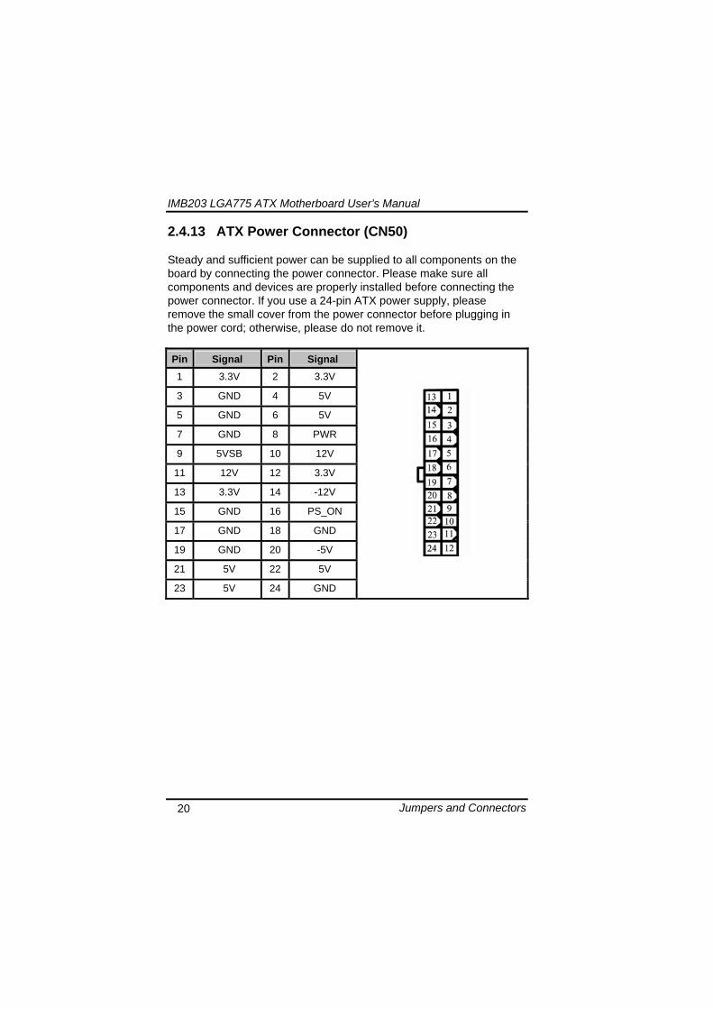
IMB203 LGA775 ATX Motherboard Userrsquos Manual
Jumpers and Connectors 20
2413 ATX Power Connector (CN50) Steady and sufficient power can be supplied to all components on the board by connecting the power connector Please make sure all components and devices are properly installed before connecting the power connector If you use a 24-pin ATX power supply please remove the small cover from the power connector before plugging in the power cord otherwise please do not remove it Pin Signal Pin Signal 1 33V 2 33V
3 GND 4 5V
5 GND 6 5V
7 GND 8 PWR
9 5VSB 10 12V
11 12V 12 33V
13 33V 14 -12V
15 GND 16 PS_ON
17 GND 18 GND
19 GND 20 -5V
21 5V 22 5V
23 5V 24 GND
IMB203 LGA775 ATX Motherboard Userrsquos Manual
Jumpers and Connectors 21
2414 Front Panel Connector (CN52)
Power LED
This 3-pin connector denoted as Pin 1 and Pin 5 connects the system power LED indicator to such a switch on the case Pin 1 is assigned as + and Pin 5 as - The Power LED lights up when the system is powered ON Pin 3 is defined as GND
External Speaker and Internal Buzzer Connector
Pin 2 4 6 and 8 can be connected to the case-mounted speaker unit or internal buzzer While connecting the CPU card to an internal buzzer please short pins 2-4 while connecting to an external speaker you need to set pins 2-4 to Open and connect the speaker cable to pin 8 (+) and pin 2 (-)
ATX Power OnOff Button
This 2-pin connector denoted as Pin 9 and 10 connects the front panelrsquos ATX power button to the CPU card which allows users to control ATX power supply to be power onoff
System Reset Switch
Pin 11 and 12 can be connected to the case-mounted reset switch that reboots your computer instead of turning OFF the power switch It is a better way to reboot your system for a longer life of the systemrsquos power supply
HDD Activity LED
This connection is linked to hard drive activity LED on the control panel LED flashes when HDD is being accessed Pin 13 and 14 connect the hard disk drive to the front panel HDD LED Pin 13 assigned as - and Pin 14 as +
IMB203 LGA775 ATX Motherboard Userrsquos Manual
Jumpers and Connectors 22
MEMO
IMB203 LGA775 ATX Motherboard Userrsquos Manual
Hardware Installation 23
CHAPTER 3 HARDWARE INSTALLATION
Before installing the processor please access Intelreg website for more detailed information httpwwwintelcom
31 Installing the Processor The LGA775 processor socket comes with a cover to protect the processor Please install the processor into the CPU socket step by step as below
Hold the hook (A) of the lever and push it down Pull the lever (B) aside to unlock the cover
IMB203 LGA775 ATX Motherboard Userrsquos Manual
Hardware Installation 24
Remove the plastic cap (E) from the cover
Open the cover (C) you can see the contact
Be careful not to touch the contact (D)
IMB203 LGA775 ATX Motherboard Userrsquos Manual
Hardware Installation 25
Place the CPU down into the socket Be careful not to touch the contact
Hold the edges of the CPU and orientate it as the marked direction (G) down into the socket to match the (H) and (F) locations
IMB203 LGA775 ATX Motherboard Userrsquos Manual
Hardware Installation 26
Slightly push down the cover and hook the lever (I~J) The CPU is completely locked
Orientate the CPU cooling fan to fixing holes on the board
IMB203 LGA775 ATX Motherboard Userrsquos Manual
Hardware Installation 27
Screw the CPU cooling fan onto the board
Make sure the CPU fan is plugged to the CPU fan connector
IMB203 LGA775 ATX Motherboard Userrsquos Manual
Hardware Installation 28
32 Installing the Memory The board supports four 240-pin DDR3 DIMM memory sockets with maximum memory capacity up to 16GB Please follow steps below to install the memory modules 1 Push down latches on each side of the DIMM socket 2 Align the memory module with the socket that notches of
memory module must match the socket keys for a correct installation
3 Install the memory module into the socket and push it firmly down until it is fully seated The socket latches are levered upwards and clipped on to the edges of the DIMM
4 Install any remaining DIMM modules
IMB203 LGA775 ATX Motherboard Userrsquos Manual
Hardware Description 29
CHAPTER 4 HARDWARE DESCRIPTION
41 Microprocessors The IMB203 Series supports Intelreg Coretrade 2 Quad Coretrade 2 Duo processors which make your system operated under Windowsreg XP and Linux environments The system performance depends on the microprocessor Make sure all correct settings are arranged for your installed microprocessor to prevent the CPU from damages
42 BIOS The IMB203 Series uses AMI Plug and Play BIOS with a single 32Mbit SPI Flash
43 System Memory The IMB203 Series supports four 240-pin DDR3 DIMM sockets for a maximum memory of 16GB DDR3 SDRAMs The memory module can come in sizes of 1GB 2GB and 4GB
IMB203 LGA775 ATX Motherboard Userrsquos Manual
Hardware Description 30
44 IO Port Address Map The Intelreg Coretrade 2 Extreme Intelreg Coretrade 2 Quad Coretrade 2 Duo CPUs can communicate via IO ports There are total 1KB port addresses available for assignment to other devices via IO expansion cards
Address Devices 000-01F DMA controller 1
020-02D 024-025 028-029 02C-02D Interrupt controller 1
02E-02F Forwarded to LPC(LPC Super IO ) 030-031 034-035 038-039 03C-03D
Interrupt controller 2
040-043 050-053 TimerCounter (8254) 060 Forwarded to LPC (Microcontroller) 061 NMI
062-066 Forwarded to LPC (Microcontroller) 070-077 Real time clock NMI 080-091 DMA page register
092 Processor IF(Reset Generator) 093-09F DMA page register 0A0-0BF Interrupt controller 2 0C0-0DF DMA controller 2
0F0 Processor IF 0F8-0FF Math processor 170-177 Forward to SATA (SATA Controller) 1F0-1F7 Forward to SATA (SATA Controller)
376 Forward to SATA(SATA Controller) 378-37F Parallel Port (LPT) 380-38F SDLC 2 3A0-3AF SDLC 1 3B0-3BF MDA video card
(to be continued)
IMB203 LGA775 ATX Motherboard Userrsquos Manual
Hardware Description 31
Address Devices 3C0-3CF EGA card 3D0-3DF CGA card
3F6 Forward to SATA(SATA Controller) 3F8-3FF Serial port 1 (COM1) 2F8-2FF Serial port 2 (COM2)
45 Interrupt Controller (IRQ) Map The IMB203 Series is a 100 PC compatible control board It consists of 16 interrupt request lines and four out of them can be programmable The mapping list of the 16 interrupt request lines is shown as the following table
IRQ Parity check error IRQ0 System Timer Output
IRQ1 Keyboard
IRQ2 Interrupt rerouting from IRQ8 through IRQ15
IRQ3 Serial port 2
IRQ4 Serial port 1
IRQ5 PCI Device Share
IRQ7 Parallel port
IRQ8 Real time clock
IRQ9 ACPI Controller
IRQ10 PCI Device Share
IRQ11 PCI Device Share
IRQ12 PS2 Mouse
IRQ13 Math coprocessor
IRQ14 SATA Primary (Legacy Mode)
IRQ15 SATA Secondary (Legacy Mode)
IMB203 LGA775 ATX Motherboard Userrsquos Manual
Hardware Description 32
MEMO
IMB203 LGA775 ATX Motherboard Userrsquos Manual
AMI BIOS Setup Utility 33
CHAPTER 5 AMI BIOS SETUP UTILITY
This chapter provides users with detailed description how to set up basic system configuration through the AMIBIOS8 BIOS setup utility 51 Starting To enter the setup screens follow the steps below 1 Turn on the computer and press the ltDelgt key immediately 2 After you press the ltDeletegt key the main BIOS setup menu
displays You can access the other setup screens from the main BIOS setup menu such as the Chipset and Power menus
52 Navigation Keys The BIOS setuputility uses a key-based navigation system called hot keys Most of the BIOS setup utility hot keys can be used at any time during the setup navigation process These keys include ltF1gt ltF10gt ltEntergt ltESCgt ltArrowgt keys and so on
Note Some of navigation keys differ from one screen to another
IMB203 LGA775 ATX Motherboard Userrsquos Manual
AMI BIOS Setup Utility 34
LeftRight The Left ltArrowgt keys allow you to select a setup screen
UpDown The Up and Down ltArrowgt keys allow you to select a setup screen or sub-screen
+minus PlusMinus The Plus and Minus ltArrowgt keys allow you to change the field value of a particular setup item
Tab The ltTabgt key allows you to select setup fields
F1 The ltF1gt key allows you to display the General Help screen
F10 The ltF10gt key allows you to save any changes you have made and exit Setup Press the ltF10gt key to save your changes
Esc
The ltEscgt key allows you to discard any changes you have made and exit the Setup Press the ltEscgt key to exit the setup without saving your changes
Enter
The ltEntergt key allows you to display or change the setup option listed for a particular setup item The ltEntergt key can also allow you to display the setup sub- screens
IMB203 LGA775 ATX Motherboard Userrsquos Manual
AMI BIOS Setup Utility 35
53 Main Menu When you first enter the Setup Utility you will enter the Main setup screen You can always return to the Main setup screen by selecting the Main tab There are two Main Setup options They are described in this section The Main BIOS Setup screen is shown below
System TimeDate
Use this option to change the system time and date Highlight System Time or System Date using the ltArrowgt keys Enter new values through the keyboard Press the ltTabgt key or the ltArrowgt keys to move between fields The date must be entered in MMDDYY format The time is entered in HHMMSS format
IMB203 LGA775 ATX Motherboard Userrsquos Manual
AMI BIOS Setup Utility 36
54 Advanced Menu The Advanced menu allows users to set configuration of the CPU and other system devices You can select any of the items in the left frame of the screen to go to the sub menus
CPU Configuration IDE Configuration SuperIO Configuration Hardware Health Configuration ACPI Configuration AHCI Configuration Intel iAMT Configuration Intel VT-d Configuration MPS Configuration PCI Express Configuration Trusted Computing USB Configuration
For items marked with ldquo rdquo please press ltEntergt for more options
IMB203 LGA775 ATX Motherboard Userrsquos Manual
AMI BIOS Setup Utility 37
CPU Configuration This screen shows the CPU Configuration and you can change the value of the selected option
Max CPUID Value Limit
You can enable this item to let legacy operating systems boot even without support for CPUs with extended CPU ID functions
Execute-Disable Bit Capability This item helps you enable or disable the No-Execution Page Protection Technology
Core Multi-Processing This feature controls the functionality of the Core Multi-Processing to allow the processor to execute multitasking function
PECI Use this item PECI (Platform Environment Control Interface) to execute the processor temperature monitoring and management
IMB203 LGA775 ATX Motherboard Userrsquos Manual
AMI BIOS Setup Utility 38
Intel (R) C-STATE tech Use this item to enable or disable the C-State technology
IDE Configuration You can use this screen to select options for the IDE Configuration and change the value of the selected option A description of the selected item appears on the right side of the screen For items marked with ldquo rdquo please press ltEntergt for more options
SATA1 Configuration
Use this item to control the onboard SATA controller Here are the options for your selection Compatible Disabled and Enhanced
Configure SATA1 as Use this item to choose the SATA operation mode Here are the options for your selection IDE and AHCI
SATA2 Configuration Use this item to control the onboard SATA controller Here are the options for your selection Enhanced and Disabled
IMB203 LGA775 ATX Motherboard Userrsquos Manual
AMI BIOS Setup Utility 39
PrimarySecondaryThird IDE Master Select one of the hard disk drives to configure IDE devices installed in the system by pressing ltEntergt for more options
Fifth IDE Master Select one of the hard disk drives to configure IDE devices installed in the system by pressing ltEntergt for more options
IMB203 LGA775 ATX Motherboard Userrsquos Manual
AMI BIOS Setup Utility 40
SuperIO Configuration You can use this screen to select options for the SuperIO Configuration and change the value of the selected option A description of the selected item appears on the right side of the screen
Serial Port1 Address
This option specifies the base IO port address and Interrupt Request address of serial port 1 The Optimal setting is 3F8IRQ4 The Fail-Safe default setting is Disabled
Serial Port2 Address This option specifies the base IO port address and Interrupt Request address of serial port 2 The Optimal setting is 2F8IRQ3 The Fail-Safe setting is Disabled
Parallel Port Address This item allows you to determine the IO address for onboard parallel port There are several options for your selection
Parallel Port Mode
IMB203 LGA775 ATX Motherboard Userrsquos Manual
AMI BIOS Setup Utility 41
Select an operating mode for the onboard parallel (printer) port
Parallel Port IRQ Use this item to set up the IRQ for onboard parallel port
Serial Port3 Address This item specifies the base IO port address and Interrupt Request address of serial port 3 The Optimal setting is 3E8IRQ11 The Fail-Safe default setting is Disabled
Serial Port3 IRQ This item specifies the IRQ used by the serial port 3
Serial Port4 Address This item specifies the base IO port address and Interrupt Request address of serial port 4 The Optimal setting is 2E8IRQ10 The Fail-Safe default setting is Disabled
Serial Port4 IRQ This item specifies the IRQ used by the serial port 4
IMB203 LGA775 ATX Motherboard Userrsquos Manual
AMI BIOS Setup Utility 42
Hardware Health Configuration This screen shows the Hardware Health Configuration and a description of the selected item appears on the right side of the screen
HW Health Configuration
This screen displays the temperature of CPU and System Fan Speed Vcore etc
IMB203 LGA775 ATX Motherboard Userrsquos Manual
AMI BIOS Setup Utility 43
ACPI Configuration You can use this screen to select options for the ACPI Configuration and change the value of the selected option A description of the selected item appears on the right side of the screen
General ACPI Configuration
Scroll to this item and press ltEntergt to view the General ACPI Configuration sub menu which contains General ACPI (Advanced Configuration and Power Management Interface) options for your configuration
Advanced ACPI Configuration Scroll to this item and press ltEntergt to view the Advanced ACPI Configuration sub menu which contains Advanced ACPI (Advanced Configuration and Power Management Interface) options for your configuration
Chipset ACPI Configuration Scroll to this item and press ltEntergt to view the Chipset ACPI Configuration sub menu which contains Chipset ACPI (Advanced Configuration and Power Management
IMB203 LGA775 ATX Motherboard Userrsquos Manual
AMI BIOS Setup Utility 44
Interface) options for your configuration AHCI Configuration
You can use this screen to select options for the AHCI Configuration and change the value of the selected option A description of the selected item appears on the right side of the screen
AHCI BIOS Support You can enable or disable this item to control the AHCI function of the SATA controller
IMB203 LGA775 ATX Motherboard Userrsquos Manual
AMI BIOS Setup Utility 45
Intel iAMT Configuration You can use this screen to select options for the Intel iAMT Configuration and change the value of the selected option A description of the selected item appears on the right side of the screen
Intel iAMT Support
You can enable this item to support iAMT (active management technology) function to follow up the procedure for the access to AMI program screen
Unconfigure iAMTME Use this item to unconfigure the iAMTME settings
IMB203 LGA775 ATX Motherboard Userrsquos Manual
AMI BIOS Setup Utility 46
Intel VT-d Configuration You can use this screen to select options for the Intel VT-d Configuration and change the value of the selected option A description of the selected item appears on the right side of the screen
Intel VT-d Virtualization Technology for Directed IO (VT-d) extends Virtualization Technology (VT) roadmap by providing hardware assists for virtualization solution VT-d can help end users improve security and reliability of the systems and also improve performance of IO devices in virtualized environment Here are the options for your selection Disabled and Enabled
IMB203 LGA775 ATX Motherboard Userrsquos Manual
AMI BIOS Setup Utility 47
Remote Access Configuration You can use this screen to select options for the Remote Access Configuration and change the value of the selected option A description of the selected item appears on the right side of the screen
Remote Access Use this item to enable or disable the Remote Access function
IMB203 LGA775 ATX Motherboard Userrsquos Manual
AMI BIOS Setup Utility 48
PCI Express Configuration This screen shows the PCI Express Configuration and you can change its value A description of the selected item appears on the right side of the screen
Active State Power-Management
Use this item to enable or disable the function of Active State Power-Management to provide you with lower power consumption The default setting is Disabled
IMB203 LGA775 ATX Motherboard Userrsquos Manual
AMI BIOS Setup Utility 49
Trusted Computing You can use this screen to select options for the Trusted Computing and change the value of the selected option A description of the selected item appears on the right side of the screen
TCGTPM SUPPORT Use this item to control the Trusted Platform Module (TPM) function
IMB203 LGA775 ATX Motherboard Userrsquos Manual
AMI BIOS Setup Utility 50
USB Configuration You can use this screen to select options for the USB Configuration and change the value of the selected option A description of the selected item appears on the right side of the screen
USB Functions
This item allows you to enable or disable USB functions
Legacy USB Support Use this item to enable or disable support for USB device on legacy operating system The default setting is Enabled
USB 20 Controller Mode Use this item to configure the USB 20 controller The default setting is HiSpeed
BIOS EHCI Hand-Off Enabling this item provide the support for operating systems without an EHCI hand-off feature The default setting is Enabled
IMB203 LGA775 ATX Motherboard Userrsquos Manual
AMI BIOS Setup Utility 51
IMB203 LGA775 ATX Motherboard Userrsquos Manual
AMI BIOS Setup Utility 52
55 PCI PnP Menu The PCI PnP menu allows users to change the advanced settings for PCIPnP devices
Clear NVRAM
Use this item to clear the data in the NVRAM (CMOS) Here are the options for your selection No and Yes
Plug amp Play OS When the setting is No Use this item to configure all the devices in the system When the setting is Yes and if you install a Plug and Play operating system the operating system configures the Plug and Play devices not required for boot The default setting is No
IMB203 LGA775 ATX Motherboard Userrsquos Manual
AMI BIOS Setup Utility 53
PCI Latency Timer This item controls how long a PCI device can hold the PCI bus before another takes over The longer the latency the longer the PCI device can retain control of the bus before handing it over to another PCI device There are several options for your selection
Allocate IRQ to PCI VGA This item allows BIOS to choose an IRQ to assign for the PCI VGA card Here are the options for your selection No and Yes
Palette Snooping Some old graphic controllers need to ldquosnooprdquo on the VGA palette and then map it to their display as a way to provide boot information and VGA compatibility This item allows such snooping to take place Here are the options for your selection Disabled and Enabled
PCI IDE BusMaster This item is a toggle for the built-in driver that allows the onboard IDE controller to perform DMA (Direct Memory Access) transfer Here are the options for your selection Disabled and Enabled
OffBoard PCIISA IDE Card This item is for any other non-onboard PCIISA IDE controller adapter There are several options for your selection
IRQ3457910111415 These items will allow you to assign each system interrupt a type depending on the type of device using the interrupt The option ldquoAvailablerdquo means the IRQ is going to assign automatically Here are the options for your selection Available and Reserved
DMA Channel 013567 These items will allow you to assign each DMA channel a type depending on the type of device using the channel The option ldquoAvailablerdquo means the channel is going to assign automatically Here are the options for your selection Available and Reserved
IMB203 LGA775 ATX Motherboard Userrsquos Manual
AMI BIOS Setup Utility 54
56 Boot Menu The Boot menu allows users to change boot options of the system You can select any of the items in the left frame of the screen to go to the sub menus
Boot Settings Configuration Boot Device Priority Removable Drives
For items marked with ldquo rdquo please press ltEntergt for more options
IMB203 LGA775 ATX Motherboard Userrsquos Manual
AMI BIOS Setup Utility 55
Boot Settings Configuration
Quick Boot
Enabling this item lets the BIOS skip some power on self tests (POST) The default setting is Enabled
AddOn ROM Display Mode This item selects the display mode for option ROM The default setting is Force BIOS
Boot Num-Lock Use this item to select the power-on state for the NumLock The default setting is On
PS2 Mouse Support This item determines if the BIOS should reserve IRQ12 for the PS2 mouse or allow other devices to make use of this IRQ Here are the options for your selection Auto Enabled and Disabled
Wait For lsquoF1rsquo Of Error If this item is enabled the system waits for the F1 key to be pressed when error occurs The default setting is Enabled
Hit lsquoDELrsquo Message Display If this item is enabled the system displays the message
IMB203 LGA775 ATX Motherboard Userrsquos Manual
AMI BIOS Setup Utility 56
ldquoPress DEL to run Setuprdquo during POST The default setting is Enabled
Interrupt 19 Capture If this item is enabled this function makes the option ROMs to trap Interrupt 19 The default setting is Disabled
Boot Device Priority The Boot Device Priority screen specifies the boot device priority sequence from the available devices
IMB203 LGA775 ATX Motherboard Userrsquos Manual
AMI BIOS Setup Utility 57
Removable Drives Use this screen to view the removable drives in the system The BIOS will attempt to arrange the removable drive boot sequence automatically You can also change the booting sequence
IMB203 LGA775 ATX Motherboard Userrsquos Manual
AMI BIOS Setup Utility 58
57 Security Menu The Security menu allows users to change the security settings for the system
Supervisor Password
This item indicates whether a supervisor password has been set If the password has been installed Installed displays If not Not Installed displays
User Password This item indicates whether a user password has been set If the password has been installed Installed displays If not Not Installed displays
Change Supervisor Password Select this option and press ltEntergt to access the sub menu You can use the sub menu to change the supervisor password
Change User Password Select this option and press ltEntergt to access the sub menu You can use the sub menu to change the user password
IMB203 LGA775 ATX Motherboard Userrsquos Manual
AMI BIOS Setup Utility 59
58 Chipset Menu The Chipset menu allows users to change the advanced chipset settings You can select any of the items in the left frame of the screen to go to the sub menus
North Bridge Configuration South Bridge Configuration ME Subsystem Configuration
For items marked with ldquo rdquo please press ltEntergt for more options
IMB203 LGA775 ATX Motherboard Userrsquos Manual
AMI BIOS Setup Utility 60
North Bridge Configuration
Memory Remap Feature
Use this item to enable or disable the remapping of the overlapped PCI memory above the total physical memory Only 64-bit OS supports this function
DRAM Frequency This item allows you to control the Memory Clock
Configure DRAM Timing by SPD This item can enable or disable DRAM timing by SPD (Serial Presence Detect) device which is a small EEPROM chip on the memory module containing important information about the module speed size addressing mode and various parameters
Memory Hole You can reserve this area of system memory for ISA adapter ROM When this area is reserved it cannot be cached Check the user information of peripherals that need to use this area o f system memory for the memory requirements Here are the options Disabled and 15M-16M
IMB203 LGA775 ATX Motherboard Userrsquos Manual
AMI BIOS Setup Utility 61
Initiate Graphic Adapter When using multiple graphics cards this item can select which graphics controller to be the primary display device during boot
IGD Graphics Mode Select This item allows you to select the amount of system memory used by the internal graphics device
PEG Port ConfigurationPEG Port This item is a toggle to enable or disable the PCI Express port Here are the options for your selection Auto and Disabled
Video Function Configuration Press ltEntergt for the sub-menu for setting up video function
IMB203 LGA775 ATX Motherboard Userrsquos Manual
AMI BIOS Setup Utility 62
South Bridge Configuration
GbE Wake Up From S5 This item specifies whether the system will be awakened from the S5 power
HDA Controller This item allows you to enable or disable the HD audio support
Restore on AC Power Loss This item can control how the PC will behave once power is restored following a power outage or other unexpected shutdown
PCIE Port Configuration This item allows you to set or disable the PCI Express Ports
IMB203 LGA775 ATX Motherboard Userrsquos Manual
AMI BIOS Setup Utility 63
ME Subsystem Configuration
It is strongly recommended that you do not modify these options unless you are an advanced user
IMB203 LGA775 ATX Motherboard Userrsquos Manual
AMI BIOS Setup Utility 64
59 Exit Menu The Exit menu allows users to load your system configuration with optimal or failsafe default values
Save Changes and Exit
When you have completed the system configuration changes select this option to leave Setup and reboot the computer so the new system configuration parameters can take effect Select Save Changes and Exit from the Exit menu and press ltEntergt Select Ok to save changes and exit
Discard Changes and Exit Select this option to quit Setup without making any permanent changes to the system configuration Select Discard Changes and Exit from the Exit menu and press ltEntergt Select Ok to discard changes and exit
Load Optimal Defaults It automatically sets all Setup options to a complete set of default settings when you select this option The Optimal settings are designed for maximum system performance but may not work best for all computer applications In particular do not use the Optimal Setup options if your
IMB203 LGA775 ATX Motherboard Userrsquos Manual
AMI BIOS Setup Utility 65
computer is experiencing system configuration problems Select Load Optimal Defaults from the Exit menu and press ltEntergt
Load Fail-Safe Defaults It automatically sets all Setup options to a complete set of default settings when you select this option The Fail-Safe settings are designed for maximum system stability but not maximum performance Select the Fail-Safe Setup options if your computer is experiencing system configuration problems Select Load Fail-Safe Defaults from the Exit menu and press ltEntergt Select Ok to load Fail-Safe defaults
IMB203 LGA775 ATX Motherboard Userrsquos Manual
AMI BIOS Setup Utility 66
MEMO
IMB203 LGA775 ATX Motherboard Userrsquos Manual
Installation of Drivers 67
CHPATER 6 INSTALLATION OF DRIVERS
The device drivers are located on the Product Information CD-ROM that comes with the IMB203 Series package The auto-run function of drivers will guide you to install the utilities and device drivers under a Windows system You can follow the onscreen instructions to install these devices
Chipse VGA LAN Audio iAMT MEI
61 Installing Chipset Driver 1 Run the SETUPEXE program from the driver directory in
your driver CD Click ldquoNextrdquo to next step
IMB203 LGA775 ATX Motherboard Userrsquos Manual
Installation of Drivers 68
2 An Intelreg License Agreement appears to show you the important information Click ldquoYesrdquo to next step
3 Refer to the Readme file below to view the system requirements and installation information
IMB203 LGA775 ATX Motherboard Userrsquos Manual
Installation of Drivers 69
3-1 Please wait while running the following setup operations
3-2 Please wait while running the following setup operations
IMB203 LGA775 ATX Motherboard Userrsquos Manual
Installation of Drivers 70
4 Click ldquoFinishrdquo to complete the setup process
5 You will be asked to reboot your computer when the installation is completed Please click ldquoYes I want to restart my computer nowrdquo if you donrsquot need to install any other drivers Otherwise please click ldquoNo I will restart my computer laterrdquo and go on next step
IMB203 LGA775 ATX Motherboard Userrsquos Manual
Installation of Drivers 71
62 Installing VGA Driver 1 Run the SETUPEXE program from the driver directory in
your driver CD Click ldquoNextrdquo to next step
2 An Intelreg License Agreement appears to show you the
important information Click ldquoYesrdquo to next step
IMB203 LGA775 ATX Motherboard Userrsquos Manual
Installation of Drivers 72
3 The message of Readme File Information appears to show you the system requirements and installation information Please click ldquoNextrdquo
4 Please wait while running the following setup operations
When this message appears please click ldquoNextrdquo
IMB203 LGA775 ATX Motherboard Userrsquos Manual
Installation of Drivers 73
5 Click ldquoFinishrdquo to complete the setup process
6 You will be asked to reboot your computer when the installation is completed Please click ldquoYes I want to restart my computer nowrdquo if you donrsquot need to install any other drivers Otherwise please click ldquoNo I will restart my computer laterrdquo and click ldquoFinishrdquo to complete the installation
IMB203 LGA775 ATX Motherboard Userrsquos Manual
Installation of Drivers 74
63 Installing LAN Driver
11 Run the InstallShield Wizard for Network Connections from
the driver directory in your driver CD Click ldquoNextrdquo to next step
IMB203 LGA775 ATX Motherboard Userrsquos Manual
Installation of Drivers 75
12 An Intelreg License Agreement appears to show you the important information Click ldquoYesrdquo to next step
13 A Setup Options window appears that you can select the
program features you want to install
IMB203 LGA775 ATX Motherboard Userrsquos Manual
Installation of Drivers 76
2 Click ldquoInstallrdquo to start the installation
3 Please wait while running the following installation operation
IMB203 LGA775 ATX Motherboard Userrsquos Manual
Installation of Drivers 77
4 Click ldquoFinishrdquo to complete the installation
Note The Driver item [Wake on Directed Packet] default is Enabled under Windows Vista
格式化 字型 (符號) Arial
格式化 字型 (符號) Arial
格式化 字型 斜體 字型色彩 黑色 (符號) Arial 非加寬 緊縮
格式化 字型 斜體 字型色彩 黑色 (符號) Arial 非加寬 緊縮
格式化 字型 (符號) Arial 非加寬 緊縮
IMB203 LGA775 ATX Motherboard Userrsquos Manual
Installation of Drivers 78
64 Installing AUDIO Driver 1 Run the InstallShield Wizard for Realtek High Definition
Audio Driver from the driver directory in your driver CD Click ldquoNextrdquo to next step
IMB203 LGA775 ATX Motherboard Userrsquos Manual
Installation of Drivers 79
2 Click ldquoInstallrdquo to start the installation and wait while running the installation operation
3 Click ldquoFinishrdquo to complete the installation
IMB203 LGA775 ATX Motherboard Userrsquos Manual
Installation of Drivers 80
65 Installing iAMT (Active Management Technology) Driver
Note You must download and properly install the required NET version 35 provided from a separate downloading of the actual FimwareTools kit releases posted on VIP prior to loading the MEILMS Driver stack
651 LMS_SOL Setup
1 Run the setup program to install Intelreg Active Management Technology onto your computer It is strongly recommended that you exit all programs before continuing Click ldquoNextrdquo to next step
格式化 字型 (符號) Arial
格式化 字型 (符號) Arial 非加寬 緊縮
IMB203 LGA775 ATX Motherboard Userrsquos Manual
Installation of Drivers 81
2 An Intelreg license agreement appears that you need to continue the setup program by clicking ldquoYesrdquo to accept the terms
IMB203 LGA775 ATX Motherboard Userrsquos Manual
Installation of Drivers 82
3 Refer to the Readme file below to view the system requirements and installation information Click ldquoNextrdquo to next setup
4 Please wait while running the following installation operation
IMB203 LGA775 ATX Motherboard Userrsquos Manual
Installation of Drivers 83
5 Click ldquoFinishrdquo to complete the installation
IMB203 LGA775 ATX Motherboard Userrsquos Manual
Installation of Drivers 84
652 LMS_SOL_IS Setup
1 Run the setup program to install Intelreg Active Management Technology onto your computer It is strongly recommended that you exit all programs before continuing Click ldquoNextrdquo to next step
IMB203 LGA775 ATX Motherboard Userrsquos Manual
Installation of Drivers 85
2 An Intelreg license agreement appears that you need to continue the setup program by clicking ldquoYesrdquo to accept the terms
IMB203 LGA775 ATX Motherboard Userrsquos Manual
Installation of Drivers 86
3 Refer to the Readme file below to view the system requirements and installation information Click ldquoNextrdquo to next setup
4 Please wait while running the following installation operation
IMB203 LGA775 ATX Motherboard Userrsquos Manual
Installation of Drivers 87
5 Click ldquoFinishrdquo to complete the installation
IMB203 LGA775 ATX Motherboard Userrsquos Manual
Installation of Drivers 88
66 Installing MEI (Management Engine Interface) Driver
Note You must download and properly install the required NET version 35 provided from a separate downloading of the actual FimwareTools kit releases posted on VIP prior to loading the MEILMS Driver stack
1 Run the setup program to install Intelreg Management Engine
Interface onto your computer It is strongly recommended that you exit all programs before continuing Click ldquoNextrdquo to next step
格式化 字型 (符號) Arial
格式化 字型 (符號) Arial 非加寬 緊縮
IMB203 LGA775 ATX Motherboard Userrsquos Manual
Installation of Drivers 89
2 An Intelreg license agreement appears that you need to continue the setup program by clicking ldquoYesrdquo to accept the terms
IMB203 LGA775 ATX Motherboard Userrsquos Manual
Installation of Drivers 90
3 Refer to the Readme file below to view the system requirements and installation information Click ldquoNextrdquo to next setup
4 Please wait while running the following installation operation
IMB203 LGA775 ATX Motherboard Userrsquos Manual
Installation of Drivers 91
5 Click ldquoFinishrdquo to complete the installation
IMB203 LGA775 ATX Motherboard Userrsquos Manual
Installation of Drivers 92
MEMO
IMB203 LGA775 ATX Motherboard Userrsquos Manual
Watchdog Timer 93
APPENDIX A WATCHDOG TIMER
Watchdog Timer Setting After the system stops working for a while it can be auto-reset by the Watchdog Timer The integrated Watchdog Timer can be set up in the system reset mode by program
Using the Watchdog Function Start darr Un-Lock WDT O 2E 87 Un-lock super IO
O 2E 87 Un-lock super IO darr Set WDT Function O 2E 2D O 2F 20 Select Logic device O 2E 07 O 2F 08 darr Activate WDT O 2E 30
O 2F 01 Set Second or Minute O 2E F5
O 2F N N=00 or 08(See below table) darr Set base timer O 2E F6
O 2F M=000102hellipFF(Hex) Value=0 to 255 darr WDT counting
re-set timer O 2E F6
O 2F M M=000102hellipFF(See below table) darr
格式化
格式化 項目符號及編號
格式化 項目符號及編號
格式化 字型 8 點 字型色彩黑色
格式化 字型 8 點 字型色彩黑色
格式化 定位點 1257 字元左 + 不在 1012 字元 + 1386字元
格式化 字型 8 點 字型色彩黑色
格式化 定位點 1257 字元左 + 不在 134 字元 + 1362字元
格式化 字型色彩 黑色
格式化 字型色彩 黑色
刪除
IMB203 LGA775 ATX Motherboard Userrsquos Manual
Watchdog Timer 94
IF No re-set timer WDT time-out generate RESET IF to disable WDT O 2E 30
O 2F 00 Can be disable at any time
N=00
M= 00h Time-out Disable 01h Time-out occurs after 1 second 02h Time-out occurs after 2 second 03h Time-out occurs after 3 second helliphelliphelliphelliphelliphelliphelliphelliphellip FFh Time-out occurs after 255 second
N=08
M= 00h Time-out Disable 01h Time-out occurs after 1 minute 02h Time-out occurs after 2 minutes 03h Time-out occurs after 3 minutes helliphelliphelliphelliphelliphelliphelliphelliphellip
FFh Time-out occurs after 255 minutes
格式化 字型色彩 黑色
格式化 字型色彩 黑色
IMB203 LGA775 ATX Motherboard Userrsquos Manual
PCI IRQ Routing 95
APPENDIX B PCI IRQ ROUTING
PICMG PCI IRQ Routing
Device ID Slot Int
PCI Slot 0 31 0 BCDA PCI Slot 1 30 1 CDAB PCI Slot 2 29 2 DABC PCI Slot 3 28 3 ABCD
IMB203 LGA775 ATX Motherboard Userrsquos Manual
PCI IRQ Routing 96
MEMO
IMB203 LGA775 ATX Motherboard Userrsquos Manual
Configuring SATA for RAID Function 97
APPENDIX C CONFIGURING SATA FOR RAID
FUNCTION
Configuring SATA Hard Drive(s) for RAID Function (Controller IntelregICH10DODO DH only) Please follow up the steps below to configure SATA hard drive(s) (1) Install SATA hard drive(s) in your system (2) Enter the BIOS Setup to configure SATA controller mode and boot
sequence (3) Configure RAID by the RAID BIOS (4) Install the SATA controller driver during the OS installation Before you begin the SATA configuration please prepare (a) Two SATA hard drives (to ensure optimal performance it is
recommended that you use two hard drives with identical model and capacity) If you do not want to create RAID with the SATA controller you may prepare only one hard drive
(b) An empty formatted floppy disk (c) Windows XP setup disk (1) Installing SATA hard drive(s) in your system
Connect one end of the SATA signal cable to the rear of the SATA hard drive and the other end to available SATA port(s) on the board Then connect the power connector of power supply to the hard drive
(2) Configuring SATA controller mode and boot sequence by the BIOS Setup You have to make sure whether the SATA controller is configured correctly by system BIOS Setup and set up BIOS boot sequence for the SATA hard drive(s)
IMB203 LGA775 ATX Motherboard Userrsquos Manual
Configuring SATA for RAID Function 98
(2)-1-1 Turn on your system and then press the Del button to enter BIOS Setup during running POST (Power-On Self Test) If you want to create RAID just go to the Advanced Settings menuIDE configuration select the Configure SATA1 as and press ltEntergt for more options
IMB203 LGA775 ATX Motherboard Userrsquos Manual
Configuring SATA for RAID Function 99
(2)-1-2 A list of options appears please select RAID
IMB203 LGA775 ATX Motherboard Userrsquos Manual
Configuring SATA for RAID Function 100
(2)-2 Set CDROM for First Boot Device under the Boot Settings menu to boot CD-ROM after system restarts
(2)-3 Save and exit the BIOS Setup
IMB203 LGA775 ATX Motherboard Userrsquos Manual
Configuring SATA for RAID Function 101
(3) Configuring RAID by the RAID BIOS Enter the RAID BIOS setup utility to configure a RAID array Skip this step and proceed to Section 4 if you do not want to create a RAID (3)-1 After the POST memory testing and before the operating
system booting a message Press ltCtrl-Igt to enter Configuration Utility shows up accordingly press ltCTRL+ Igt to enter the RAID BIOS setup utility
(3)-2 After you press ltCTRL+ Igt the Create RAID Volume screen will appear If you want to create a RAID array select the Create RAID Volume option in the Main Menu and press ENTER
IMB203 LGA775 ATX Motherboard Userrsquos Manual
Configuring SATA for RAID Function 102
(3)-3-1 After entering the CREATE VOLUME MENU screen you can type the disk array name with 1~16 letters (letters cannot be special characters) in the item ldquoNamerdquo
(3)-3-2 When finished press ENTER to select a RAID level There are three RAID levels RAID0 RAID1 and RAID5 amp RAID10 Select a RAID level and press ENTER
IMB203 LGA775 ATX Motherboard Userrsquos Manual
Configuring SATA for RAID Function 103
(3)-4 Set the stripe block size The KB is the standard unit of stripe block size The stripe block size can be 4KB to 128KB After the setting press ENTER for the array capacity
(3)-5 After setting all the items on the menu select Create Volume
and press ENTER to start creating the RAID array
IMB203 LGA775 ATX Motherboard Userrsquos Manual
Configuring SATA for RAID Function 104
(3)-6 When prompting the confirmation press ldquoYldquo to create this volume or ldquoNldquo to cancel the creation
After the creation is completed you can see detailed information about the RAID Array in the DISKVOLUME INFORMATION section including RAID mode disk block size disk name and disk capacity etc
IMB203 LGA775 ATX Motherboard Userrsquos Manual
Configuring SATA for RAID Function 105
Delete RAID Volume If you want to delete a RAID volume select the Delete RAID Volume option in Main Menu Press ENTER and follow on-screen instructions
Please press [ESC] to exit the RAID BIOS utility Now you can proceed to install a SATA driver controller and the operating system
IMB203 LGA775 ATX Motherboard Userrsquos Manual
Configuring SATA for RAID Function 106
(4) Making a SATA Driver Disk To install the operating system onto a serial ATA hard disk successfully you need to install the SATA controller driver during the OS installation Without the driver the hard disk may not be recognized during the Windows setup process First of all please format a blank floppy disk Secondly follow up these steps below to produce a SATA driver disk Users can insert the Driver CD and the formatted blank floppy disk in another system And then please copy all of file of the f6flpy32 folder in the Driver CD to a floppy disk Note Please copy all of file of the f6flpy64 folder if installing 64-bit
Windows Operating System
IMB203 LGA775 ATX Motherboard Userrsquos Manual
Configuring SATA for RAID Function 107
(5) Installing the SATA controller driver during the OS installation Now the SATA driver disk is ready and BIOS settings configured you can proceed to install Windows 2000XP onto your SATA hard drive using the SATA driver Here is an example for Windows XP installation (5)-1 Restart your system to boot the Windows 2000XP Setup disk
and press F6 button as soon as you see the message Press F6 if you need to install a 3rd party SCSI or RAID driver After pressing the F6 button there will be a few moments for some files being loaded before next screen appears
IMB203 LGA775 ATX Motherboard Userrsquos Manual
Configuring SATA for RAID Function 108
(5)-2 When you see the screen below insert the floppy disk containing the SATA driver and press ldquoSrdquo
(5)-3 If the Setup correctly recognizes the driver of the floppy disk
a controller menu will appear below Use the ARROW keys to select Intel(R) ICH8RICH9RICH10RDO SATA RAID Controller and press ENTER Then it will begin to load the SATA driver from the floppy disk
IMB203 LGA775 ATX Motherboard Userrsquos Manual
Configuring SATA for RAID Function 109
Note If a message on the screen saying that one or some file(s) cannot be found please check the floppy disk or copy the correct SATA driver again from the driver CD
IMB203 LGA775 ATX Motherboard Userrsquos Manual
Configuring SATA for RAID Function 110
MEMO
IMB203 LGA775 ATX Motherboard Userrsquos Manual
iAMT Settings 111
APPENDIX D iAMT SETTINGS
The Intelreg Active Management Technology (Intelreg iAMT) has decreased a major barrier to IT efficiency that uses built-in platform capabilities and popular third-party management and security applications to allow IT a better discovering healing and protection their networked computing assets In order to utilize Intel iAMT you must enter the ME BIOS (CTRL + P during system startup) change the ME BIOS password and then select ldquoIntelreg iAMTrdquo as the manageability feature
D1 Entering MEBx 1 You must go to BIOS TO start iAMT function 2 Exit from BIOS after starting iAMT and press Ctrl+P to enter MEBx Setting
It is better to press Ctrl+P before the screen popping out
格式化
IMB203 LGA775 ATX Motherboard Userrsquos Manual
iAMT Settings 112
D2 Set amp Change Password 1 You will be asked to set a password when first log in The default
password is lsquoadminrsquo
2 You will be asked to change the password before setting ME
Change Password
IMB203 LGA775 ATX Motherboard Userrsquos Manual
iAMT Settings 113
3 You must confirm your new password while revising (as Remark 1)
Remark 1 The new password must contain (example 11qqQQ) (default value)
Eight characters
One upper case
One lower case
One number
One special symbol such as $ or
( excepted)
Underline ( _ ) and space are valid characters for password but they wonrsquot make higher complexity
IMB203 LGA775 ATX Motherboard Userrsquos Manual
iAMT Settings 114
D3 Intelreg iAMT Settings 1 Select Intelreg iAMT Configuration and press ltENTERgt
2 Key in the Host Name If Intelreg iAMT set to lsquoDHCPlsquo the Host name must be identical to the operating system mechanic
IMB203 LGA775 ATX Motherboard Userrsquos Manual
iAMT Settings 115
3 Select TCPIP to get into Network interface and set it to lsquoENABLEDrsquo into DHCP Mode and set it to lsquoDISABLEDrsquo (as Remark 2) into Domain name and set the Intel Management Engine domain name such as lsquoAMTintelcomrsquo
(3-1)
(3-2)
IMB203 LGA775 ATX Motherboard Userrsquos Manual
iAMT Settings 116
Remark 2 DHCP Mode lsquoDISABLEDlsquo if DHCP Mode is disabled you can make the following settings
IP address
Subnet mask
IMB203 LGA775 ATX Motherboard Userrsquos Manual
iAMT Settings 117
Default Gateway address
Preferred DNS address
IMB203 LGA775 ATX Motherboard Userrsquos Manual
iAMT Settings 118
Alternate DNS address
Domain name
4 Exit from MEBx after completing the iAMT settings
IMB203 LGA775 ATX Motherboard Userrsquos Manual
iAMT Settings 119
D4 iAMT Web Console 1 From a web browser please type http(IP ADDRESS)16992
which connects to iAMT Web Example http1014021416992
2 To log on you will be required to type in username and password
for access to the Web
USER admin (default value)
PASS (MEBx password)
IMB203 LGA775 ATX Motherboard Userrsquos Manual
iAMT Settings 120
3 Enter the iAMT Web
4 Click Remote Control and select commands on the right side
IMB203 LGA775 ATX Motherboard Userrsquos Manual
iAMT Settings 121
5 When you have finished using the iAMT Web console close the Web browser
IMB203 LGA775 ATX Motherboard Userrsquos Manual
iAMT Settings 122
MEMO
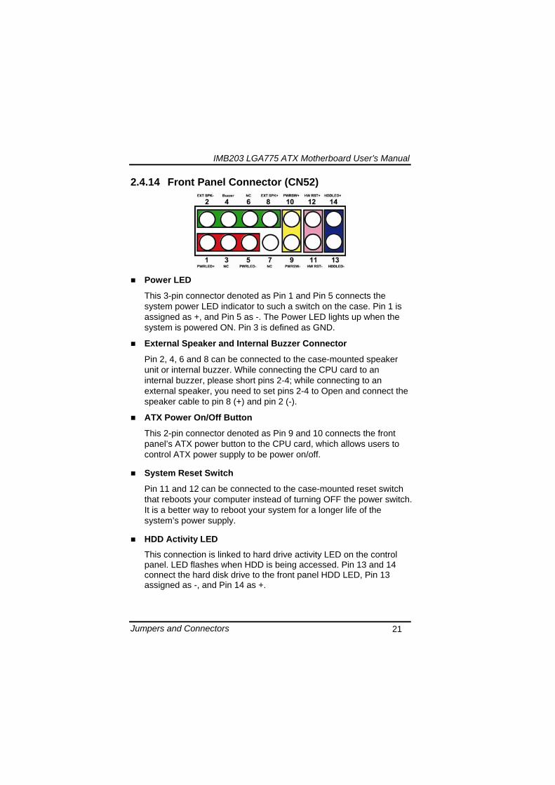
IMB203 LGA775 ATX Motherboard Userrsquos Manual
Hardware Installation 24
Remove the plastic cap (E) from the cover
Open the cover (C) you can see the contact
Be careful not to touch the contact (D)
IMB203 LGA775 ATX Motherboard Userrsquos Manual
Hardware Installation 25
Place the CPU down into the socket Be careful not to touch the contact
Hold the edges of the CPU and orientate it as the marked direction (G) down into the socket to match the (H) and (F) locations
IMB203 LGA775 ATX Motherboard Userrsquos Manual
Hardware Installation 26
Slightly push down the cover and hook the lever (I~J) The CPU is completely locked
Orientate the CPU cooling fan to fixing holes on the board
IMB203 LGA775 ATX Motherboard Userrsquos Manual
Hardware Installation 27
Screw the CPU cooling fan onto the board
Make sure the CPU fan is plugged to the CPU fan connector
IMB203 LGA775 ATX Motherboard Userrsquos Manual
Hardware Installation 28
32 Installing the Memory The board supports four 240-pin DDR3 DIMM memory sockets with maximum memory capacity up to 16GB Please follow steps below to install the memory modules 1 Push down latches on each side of the DIMM socket 2 Align the memory module with the socket that notches of
memory module must match the socket keys for a correct installation
3 Install the memory module into the socket and push it firmly down until it is fully seated The socket latches are levered upwards and clipped on to the edges of the DIMM
4 Install any remaining DIMM modules
IMB203 LGA775 ATX Motherboard Userrsquos Manual
Hardware Description 29
CHAPTER 4 HARDWARE DESCRIPTION
41 Microprocessors The IMB203 Series supports Intelreg Coretrade 2 Quad Coretrade 2 Duo processors which make your system operated under Windowsreg XP and Linux environments The system performance depends on the microprocessor Make sure all correct settings are arranged for your installed microprocessor to prevent the CPU from damages
42 BIOS The IMB203 Series uses AMI Plug and Play BIOS with a single 32Mbit SPI Flash
43 System Memory The IMB203 Series supports four 240-pin DDR3 DIMM sockets for a maximum memory of 16GB DDR3 SDRAMs The memory module can come in sizes of 1GB 2GB and 4GB
IMB203 LGA775 ATX Motherboard Userrsquos Manual
Hardware Description 30
44 IO Port Address Map The Intelreg Coretrade 2 Extreme Intelreg Coretrade 2 Quad Coretrade 2 Duo CPUs can communicate via IO ports There are total 1KB port addresses available for assignment to other devices via IO expansion cards
Address Devices 000-01F DMA controller 1
020-02D 024-025 028-029 02C-02D Interrupt controller 1
02E-02F Forwarded to LPC(LPC Super IO ) 030-031 034-035 038-039 03C-03D
Interrupt controller 2
040-043 050-053 TimerCounter (8254) 060 Forwarded to LPC (Microcontroller) 061 NMI
062-066 Forwarded to LPC (Microcontroller) 070-077 Real time clock NMI 080-091 DMA page register
092 Processor IF(Reset Generator) 093-09F DMA page register 0A0-0BF Interrupt controller 2 0C0-0DF DMA controller 2
0F0 Processor IF 0F8-0FF Math processor 170-177 Forward to SATA (SATA Controller) 1F0-1F7 Forward to SATA (SATA Controller)
376 Forward to SATA(SATA Controller) 378-37F Parallel Port (LPT) 380-38F SDLC 2 3A0-3AF SDLC 1 3B0-3BF MDA video card
(to be continued)
IMB203 LGA775 ATX Motherboard Userrsquos Manual
Hardware Description 31
Address Devices 3C0-3CF EGA card 3D0-3DF CGA card
3F6 Forward to SATA(SATA Controller) 3F8-3FF Serial port 1 (COM1) 2F8-2FF Serial port 2 (COM2)
45 Interrupt Controller (IRQ) Map The IMB203 Series is a 100 PC compatible control board It consists of 16 interrupt request lines and four out of them can be programmable The mapping list of the 16 interrupt request lines is shown as the following table
IRQ Parity check error IRQ0 System Timer Output
IRQ1 Keyboard
IRQ2 Interrupt rerouting from IRQ8 through IRQ15
IRQ3 Serial port 2
IRQ4 Serial port 1
IRQ5 PCI Device Share
IRQ7 Parallel port
IRQ8 Real time clock
IRQ9 ACPI Controller
IRQ10 PCI Device Share
IRQ11 PCI Device Share
IRQ12 PS2 Mouse
IRQ13 Math coprocessor
IRQ14 SATA Primary (Legacy Mode)
IRQ15 SATA Secondary (Legacy Mode)
IMB203 LGA775 ATX Motherboard Userrsquos Manual
Hardware Description 32
MEMO
IMB203 LGA775 ATX Motherboard Userrsquos Manual
AMI BIOS Setup Utility 33
CHAPTER 5 AMI BIOS SETUP UTILITY
This chapter provides users with detailed description how to set up basic system configuration through the AMIBIOS8 BIOS setup utility 51 Starting To enter the setup screens follow the steps below 1 Turn on the computer and press the ltDelgt key immediately 2 After you press the ltDeletegt key the main BIOS setup menu
displays You can access the other setup screens from the main BIOS setup menu such as the Chipset and Power menus
52 Navigation Keys The BIOS setuputility uses a key-based navigation system called hot keys Most of the BIOS setup utility hot keys can be used at any time during the setup navigation process These keys include ltF1gt ltF10gt ltEntergt ltESCgt ltArrowgt keys and so on
Note Some of navigation keys differ from one screen to another
IMB203 LGA775 ATX Motherboard Userrsquos Manual
AMI BIOS Setup Utility 34
LeftRight The Left ltArrowgt keys allow you to select a setup screen
UpDown The Up and Down ltArrowgt keys allow you to select a setup screen or sub-screen
+minus PlusMinus The Plus and Minus ltArrowgt keys allow you to change the field value of a particular setup item
Tab The ltTabgt key allows you to select setup fields
F1 The ltF1gt key allows you to display the General Help screen
F10 The ltF10gt key allows you to save any changes you have made and exit Setup Press the ltF10gt key to save your changes
Esc
The ltEscgt key allows you to discard any changes you have made and exit the Setup Press the ltEscgt key to exit the setup without saving your changes
Enter
The ltEntergt key allows you to display or change the setup option listed for a particular setup item The ltEntergt key can also allow you to display the setup sub- screens
IMB203 LGA775 ATX Motherboard Userrsquos Manual
AMI BIOS Setup Utility 35
53 Main Menu When you first enter the Setup Utility you will enter the Main setup screen You can always return to the Main setup screen by selecting the Main tab There are two Main Setup options They are described in this section The Main BIOS Setup screen is shown below
System TimeDate
Use this option to change the system time and date Highlight System Time or System Date using the ltArrowgt keys Enter new values through the keyboard Press the ltTabgt key or the ltArrowgt keys to move between fields The date must be entered in MMDDYY format The time is entered in HHMMSS format
IMB203 LGA775 ATX Motherboard Userrsquos Manual
AMI BIOS Setup Utility 36
54 Advanced Menu The Advanced menu allows users to set configuration of the CPU and other system devices You can select any of the items in the left frame of the screen to go to the sub menus
CPU Configuration IDE Configuration SuperIO Configuration Hardware Health Configuration ACPI Configuration AHCI Configuration Intel iAMT Configuration Intel VT-d Configuration MPS Configuration PCI Express Configuration Trusted Computing USB Configuration
For items marked with ldquo rdquo please press ltEntergt for more options
IMB203 LGA775 ATX Motherboard Userrsquos Manual
AMI BIOS Setup Utility 37
CPU Configuration This screen shows the CPU Configuration and you can change the value of the selected option
Max CPUID Value Limit
You can enable this item to let legacy operating systems boot even without support for CPUs with extended CPU ID functions
Execute-Disable Bit Capability This item helps you enable or disable the No-Execution Page Protection Technology
Core Multi-Processing This feature controls the functionality of the Core Multi-Processing to allow the processor to execute multitasking function
PECI Use this item PECI (Platform Environment Control Interface) to execute the processor temperature monitoring and management
IMB203 LGA775 ATX Motherboard Userrsquos Manual
AMI BIOS Setup Utility 38
Intel (R) C-STATE tech Use this item to enable or disable the C-State technology
IDE Configuration You can use this screen to select options for the IDE Configuration and change the value of the selected option A description of the selected item appears on the right side of the screen For items marked with ldquo rdquo please press ltEntergt for more options
SATA1 Configuration
Use this item to control the onboard SATA controller Here are the options for your selection Compatible Disabled and Enhanced
Configure SATA1 as Use this item to choose the SATA operation mode Here are the options for your selection IDE and AHCI
SATA2 Configuration Use this item to control the onboard SATA controller Here are the options for your selection Enhanced and Disabled
IMB203 LGA775 ATX Motherboard Userrsquos Manual
AMI BIOS Setup Utility 39
PrimarySecondaryThird IDE Master Select one of the hard disk drives to configure IDE devices installed in the system by pressing ltEntergt for more options
Fifth IDE Master Select one of the hard disk drives to configure IDE devices installed in the system by pressing ltEntergt for more options
IMB203 LGA775 ATX Motherboard Userrsquos Manual
AMI BIOS Setup Utility 40
SuperIO Configuration You can use this screen to select options for the SuperIO Configuration and change the value of the selected option A description of the selected item appears on the right side of the screen
Serial Port1 Address
This option specifies the base IO port address and Interrupt Request address of serial port 1 The Optimal setting is 3F8IRQ4 The Fail-Safe default setting is Disabled
Serial Port2 Address This option specifies the base IO port address and Interrupt Request address of serial port 2 The Optimal setting is 2F8IRQ3 The Fail-Safe setting is Disabled
Parallel Port Address This item allows you to determine the IO address for onboard parallel port There are several options for your selection
Parallel Port Mode
IMB203 LGA775 ATX Motherboard Userrsquos Manual
AMI BIOS Setup Utility 41
Select an operating mode for the onboard parallel (printer) port
Parallel Port IRQ Use this item to set up the IRQ for onboard parallel port
Serial Port3 Address This item specifies the base IO port address and Interrupt Request address of serial port 3 The Optimal setting is 3E8IRQ11 The Fail-Safe default setting is Disabled
Serial Port3 IRQ This item specifies the IRQ used by the serial port 3
Serial Port4 Address This item specifies the base IO port address and Interrupt Request address of serial port 4 The Optimal setting is 2E8IRQ10 The Fail-Safe default setting is Disabled
Serial Port4 IRQ This item specifies the IRQ used by the serial port 4
IMB203 LGA775 ATX Motherboard Userrsquos Manual
AMI BIOS Setup Utility 42
Hardware Health Configuration This screen shows the Hardware Health Configuration and a description of the selected item appears on the right side of the screen
HW Health Configuration
This screen displays the temperature of CPU and System Fan Speed Vcore etc
IMB203 LGA775 ATX Motherboard Userrsquos Manual
AMI BIOS Setup Utility 43
ACPI Configuration You can use this screen to select options for the ACPI Configuration and change the value of the selected option A description of the selected item appears on the right side of the screen
General ACPI Configuration
Scroll to this item and press ltEntergt to view the General ACPI Configuration sub menu which contains General ACPI (Advanced Configuration and Power Management Interface) options for your configuration
Advanced ACPI Configuration Scroll to this item and press ltEntergt to view the Advanced ACPI Configuration sub menu which contains Advanced ACPI (Advanced Configuration and Power Management Interface) options for your configuration
Chipset ACPI Configuration Scroll to this item and press ltEntergt to view the Chipset ACPI Configuration sub menu which contains Chipset ACPI (Advanced Configuration and Power Management
IMB203 LGA775 ATX Motherboard Userrsquos Manual
AMI BIOS Setup Utility 44
Interface) options for your configuration AHCI Configuration
You can use this screen to select options for the AHCI Configuration and change the value of the selected option A description of the selected item appears on the right side of the screen
AHCI BIOS Support You can enable or disable this item to control the AHCI function of the SATA controller
IMB203 LGA775 ATX Motherboard Userrsquos Manual
AMI BIOS Setup Utility 45
Intel iAMT Configuration You can use this screen to select options for the Intel iAMT Configuration and change the value of the selected option A description of the selected item appears on the right side of the screen
Intel iAMT Support
You can enable this item to support iAMT (active management technology) function to follow up the procedure for the access to AMI program screen
Unconfigure iAMTME Use this item to unconfigure the iAMTME settings
IMB203 LGA775 ATX Motherboard Userrsquos Manual
AMI BIOS Setup Utility 46
Intel VT-d Configuration You can use this screen to select options for the Intel VT-d Configuration and change the value of the selected option A description of the selected item appears on the right side of the screen
Intel VT-d Virtualization Technology for Directed IO (VT-d) extends Virtualization Technology (VT) roadmap by providing hardware assists for virtualization solution VT-d can help end users improve security and reliability of the systems and also improve performance of IO devices in virtualized environment Here are the options for your selection Disabled and Enabled
IMB203 LGA775 ATX Motherboard Userrsquos Manual
AMI BIOS Setup Utility 47
Remote Access Configuration You can use this screen to select options for the Remote Access Configuration and change the value of the selected option A description of the selected item appears on the right side of the screen
Remote Access Use this item to enable or disable the Remote Access function
IMB203 LGA775 ATX Motherboard Userrsquos Manual
AMI BIOS Setup Utility 48
PCI Express Configuration This screen shows the PCI Express Configuration and you can change its value A description of the selected item appears on the right side of the screen
Active State Power-Management
Use this item to enable or disable the function of Active State Power-Management to provide you with lower power consumption The default setting is Disabled
IMB203 LGA775 ATX Motherboard Userrsquos Manual
AMI BIOS Setup Utility 49
Trusted Computing You can use this screen to select options for the Trusted Computing and change the value of the selected option A description of the selected item appears on the right side of the screen
TCGTPM SUPPORT Use this item to control the Trusted Platform Module (TPM) function
IMB203 LGA775 ATX Motherboard Userrsquos Manual
AMI BIOS Setup Utility 50
USB Configuration You can use this screen to select options for the USB Configuration and change the value of the selected option A description of the selected item appears on the right side of the screen
USB Functions
This item allows you to enable or disable USB functions
Legacy USB Support Use this item to enable or disable support for USB device on legacy operating system The default setting is Enabled
USB 20 Controller Mode Use this item to configure the USB 20 controller The default setting is HiSpeed
BIOS EHCI Hand-Off Enabling this item provide the support for operating systems without an EHCI hand-off feature The default setting is Enabled
IMB203 LGA775 ATX Motherboard Userrsquos Manual
AMI BIOS Setup Utility 51
IMB203 LGA775 ATX Motherboard Userrsquos Manual
AMI BIOS Setup Utility 52
55 PCI PnP Menu The PCI PnP menu allows users to change the advanced settings for PCIPnP devices
Clear NVRAM
Use this item to clear the data in the NVRAM (CMOS) Here are the options for your selection No and Yes
Plug amp Play OS When the setting is No Use this item to configure all the devices in the system When the setting is Yes and if you install a Plug and Play operating system the operating system configures the Plug and Play devices not required for boot The default setting is No
IMB203 LGA775 ATX Motherboard Userrsquos Manual
AMI BIOS Setup Utility 53
PCI Latency Timer This item controls how long a PCI device can hold the PCI bus before another takes over The longer the latency the longer the PCI device can retain control of the bus before handing it over to another PCI device There are several options for your selection
Allocate IRQ to PCI VGA This item allows BIOS to choose an IRQ to assign for the PCI VGA card Here are the options for your selection No and Yes
Palette Snooping Some old graphic controllers need to ldquosnooprdquo on the VGA palette and then map it to their display as a way to provide boot information and VGA compatibility This item allows such snooping to take place Here are the options for your selection Disabled and Enabled
PCI IDE BusMaster This item is a toggle for the built-in driver that allows the onboard IDE controller to perform DMA (Direct Memory Access) transfer Here are the options for your selection Disabled and Enabled
OffBoard PCIISA IDE Card This item is for any other non-onboard PCIISA IDE controller adapter There are several options for your selection
IRQ3457910111415 These items will allow you to assign each system interrupt a type depending on the type of device using the interrupt The option ldquoAvailablerdquo means the IRQ is going to assign automatically Here are the options for your selection Available and Reserved
DMA Channel 013567 These items will allow you to assign each DMA channel a type depending on the type of device using the channel The option ldquoAvailablerdquo means the channel is going to assign automatically Here are the options for your selection Available and Reserved
IMB203 LGA775 ATX Motherboard Userrsquos Manual
AMI BIOS Setup Utility 54
56 Boot Menu The Boot menu allows users to change boot options of the system You can select any of the items in the left frame of the screen to go to the sub menus
Boot Settings Configuration Boot Device Priority Removable Drives
For items marked with ldquo rdquo please press ltEntergt for more options
IMB203 LGA775 ATX Motherboard Userrsquos Manual
AMI BIOS Setup Utility 55
Boot Settings Configuration
Quick Boot
Enabling this item lets the BIOS skip some power on self tests (POST) The default setting is Enabled
AddOn ROM Display Mode This item selects the display mode for option ROM The default setting is Force BIOS
Boot Num-Lock Use this item to select the power-on state for the NumLock The default setting is On
PS2 Mouse Support This item determines if the BIOS should reserve IRQ12 for the PS2 mouse or allow other devices to make use of this IRQ Here are the options for your selection Auto Enabled and Disabled
Wait For lsquoF1rsquo Of Error If this item is enabled the system waits for the F1 key to be pressed when error occurs The default setting is Enabled
Hit lsquoDELrsquo Message Display If this item is enabled the system displays the message
IMB203 LGA775 ATX Motherboard Userrsquos Manual
AMI BIOS Setup Utility 56
ldquoPress DEL to run Setuprdquo during POST The default setting is Enabled
Interrupt 19 Capture If this item is enabled this function makes the option ROMs to trap Interrupt 19 The default setting is Disabled
Boot Device Priority The Boot Device Priority screen specifies the boot device priority sequence from the available devices
IMB203 LGA775 ATX Motherboard Userrsquos Manual
AMI BIOS Setup Utility 57
Removable Drives Use this screen to view the removable drives in the system The BIOS will attempt to arrange the removable drive boot sequence automatically You can also change the booting sequence
IMB203 LGA775 ATX Motherboard Userrsquos Manual
AMI BIOS Setup Utility 58
57 Security Menu The Security menu allows users to change the security settings for the system
Supervisor Password
This item indicates whether a supervisor password has been set If the password has been installed Installed displays If not Not Installed displays
User Password This item indicates whether a user password has been set If the password has been installed Installed displays If not Not Installed displays
Change Supervisor Password Select this option and press ltEntergt to access the sub menu You can use the sub menu to change the supervisor password
Change User Password Select this option and press ltEntergt to access the sub menu You can use the sub menu to change the user password
IMB203 LGA775 ATX Motherboard Userrsquos Manual
AMI BIOS Setup Utility 59
58 Chipset Menu The Chipset menu allows users to change the advanced chipset settings You can select any of the items in the left frame of the screen to go to the sub menus
North Bridge Configuration South Bridge Configuration ME Subsystem Configuration
For items marked with ldquo rdquo please press ltEntergt for more options
IMB203 LGA775 ATX Motherboard Userrsquos Manual
AMI BIOS Setup Utility 60
North Bridge Configuration
Memory Remap Feature
Use this item to enable or disable the remapping of the overlapped PCI memory above the total physical memory Only 64-bit OS supports this function
DRAM Frequency This item allows you to control the Memory Clock
Configure DRAM Timing by SPD This item can enable or disable DRAM timing by SPD (Serial Presence Detect) device which is a small EEPROM chip on the memory module containing important information about the module speed size addressing mode and various parameters
Memory Hole You can reserve this area of system memory for ISA adapter ROM When this area is reserved it cannot be cached Check the user information of peripherals that need to use this area o f system memory for the memory requirements Here are the options Disabled and 15M-16M
IMB203 LGA775 ATX Motherboard Userrsquos Manual
AMI BIOS Setup Utility 61
Initiate Graphic Adapter When using multiple graphics cards this item can select which graphics controller to be the primary display device during boot
IGD Graphics Mode Select This item allows you to select the amount of system memory used by the internal graphics device
PEG Port ConfigurationPEG Port This item is a toggle to enable or disable the PCI Express port Here are the options for your selection Auto and Disabled
Video Function Configuration Press ltEntergt for the sub-menu for setting up video function
IMB203 LGA775 ATX Motherboard Userrsquos Manual
AMI BIOS Setup Utility 62
South Bridge Configuration
GbE Wake Up From S5 This item specifies whether the system will be awakened from the S5 power
HDA Controller This item allows you to enable or disable the HD audio support
Restore on AC Power Loss This item can control how the PC will behave once power is restored following a power outage or other unexpected shutdown
PCIE Port Configuration This item allows you to set or disable the PCI Express Ports
IMB203 LGA775 ATX Motherboard Userrsquos Manual
AMI BIOS Setup Utility 63
ME Subsystem Configuration
It is strongly recommended that you do not modify these options unless you are an advanced user
IMB203 LGA775 ATX Motherboard Userrsquos Manual
AMI BIOS Setup Utility 64
59 Exit Menu The Exit menu allows users to load your system configuration with optimal or failsafe default values
Save Changes and Exit
When you have completed the system configuration changes select this option to leave Setup and reboot the computer so the new system configuration parameters can take effect Select Save Changes and Exit from the Exit menu and press ltEntergt Select Ok to save changes and exit
Discard Changes and Exit Select this option to quit Setup without making any permanent changes to the system configuration Select Discard Changes and Exit from the Exit menu and press ltEntergt Select Ok to discard changes and exit
Load Optimal Defaults It automatically sets all Setup options to a complete set of default settings when you select this option The Optimal settings are designed for maximum system performance but may not work best for all computer applications In particular do not use the Optimal Setup options if your
IMB203 LGA775 ATX Motherboard Userrsquos Manual
AMI BIOS Setup Utility 65
computer is experiencing system configuration problems Select Load Optimal Defaults from the Exit menu and press ltEntergt
Load Fail-Safe Defaults It automatically sets all Setup options to a complete set of default settings when you select this option The Fail-Safe settings are designed for maximum system stability but not maximum performance Select the Fail-Safe Setup options if your computer is experiencing system configuration problems Select Load Fail-Safe Defaults from the Exit menu and press ltEntergt Select Ok to load Fail-Safe defaults
IMB203 LGA775 ATX Motherboard Userrsquos Manual
AMI BIOS Setup Utility 66
MEMO
IMB203 LGA775 ATX Motherboard Userrsquos Manual
Installation of Drivers 67
CHPATER 6 INSTALLATION OF DRIVERS
The device drivers are located on the Product Information CD-ROM that comes with the IMB203 Series package The auto-run function of drivers will guide you to install the utilities and device drivers under a Windows system You can follow the onscreen instructions to install these devices
Chipse VGA LAN Audio iAMT MEI
61 Installing Chipset Driver 1 Run the SETUPEXE program from the driver directory in
your driver CD Click ldquoNextrdquo to next step
IMB203 LGA775 ATX Motherboard Userrsquos Manual
Installation of Drivers 68
2 An Intelreg License Agreement appears to show you the important information Click ldquoYesrdquo to next step
3 Refer to the Readme file below to view the system requirements and installation information
IMB203 LGA775 ATX Motherboard Userrsquos Manual
Installation of Drivers 69
3-1 Please wait while running the following setup operations
3-2 Please wait while running the following setup operations
IMB203 LGA775 ATX Motherboard Userrsquos Manual
Installation of Drivers 70
4 Click ldquoFinishrdquo to complete the setup process
5 You will be asked to reboot your computer when the installation is completed Please click ldquoYes I want to restart my computer nowrdquo if you donrsquot need to install any other drivers Otherwise please click ldquoNo I will restart my computer laterrdquo and go on next step
IMB203 LGA775 ATX Motherboard Userrsquos Manual
Installation of Drivers 71
62 Installing VGA Driver 1 Run the SETUPEXE program from the driver directory in
your driver CD Click ldquoNextrdquo to next step
2 An Intelreg License Agreement appears to show you the
important information Click ldquoYesrdquo to next step
IMB203 LGA775 ATX Motherboard Userrsquos Manual
Installation of Drivers 72
3 The message of Readme File Information appears to show you the system requirements and installation information Please click ldquoNextrdquo
4 Please wait while running the following setup operations
When this message appears please click ldquoNextrdquo
IMB203 LGA775 ATX Motherboard Userrsquos Manual
Installation of Drivers 73
5 Click ldquoFinishrdquo to complete the setup process
6 You will be asked to reboot your computer when the installation is completed Please click ldquoYes I want to restart my computer nowrdquo if you donrsquot need to install any other drivers Otherwise please click ldquoNo I will restart my computer laterrdquo and click ldquoFinishrdquo to complete the installation
IMB203 LGA775 ATX Motherboard Userrsquos Manual
Installation of Drivers 74
63 Installing LAN Driver
11 Run the InstallShield Wizard for Network Connections from
the driver directory in your driver CD Click ldquoNextrdquo to next step
IMB203 LGA775 ATX Motherboard Userrsquos Manual
Installation of Drivers 75
12 An Intelreg License Agreement appears to show you the important information Click ldquoYesrdquo to next step
13 A Setup Options window appears that you can select the
program features you want to install
IMB203 LGA775 ATX Motherboard Userrsquos Manual
Installation of Drivers 76
2 Click ldquoInstallrdquo to start the installation
3 Please wait while running the following installation operation
IMB203 LGA775 ATX Motherboard Userrsquos Manual
Installation of Drivers 77
4 Click ldquoFinishrdquo to complete the installation
Note The Driver item [Wake on Directed Packet] default is Enabled under Windows Vista
格式化 字型 (符號) Arial
格式化 字型 (符號) Arial
格式化 字型 斜體 字型色彩 黑色 (符號) Arial 非加寬 緊縮
格式化 字型 斜體 字型色彩 黑色 (符號) Arial 非加寬 緊縮
格式化 字型 (符號) Arial 非加寬 緊縮
IMB203 LGA775 ATX Motherboard Userrsquos Manual
Installation of Drivers 78
64 Installing AUDIO Driver 1 Run the InstallShield Wizard for Realtek High Definition
Audio Driver from the driver directory in your driver CD Click ldquoNextrdquo to next step
IMB203 LGA775 ATX Motherboard Userrsquos Manual
Installation of Drivers 79
2 Click ldquoInstallrdquo to start the installation and wait while running the installation operation
3 Click ldquoFinishrdquo to complete the installation
IMB203 LGA775 ATX Motherboard Userrsquos Manual
Installation of Drivers 80
65 Installing iAMT (Active Management Technology) Driver
Note You must download and properly install the required NET version 35 provided from a separate downloading of the actual FimwareTools kit releases posted on VIP prior to loading the MEILMS Driver stack
651 LMS_SOL Setup
1 Run the setup program to install Intelreg Active Management Technology onto your computer It is strongly recommended that you exit all programs before continuing Click ldquoNextrdquo to next step
格式化 字型 (符號) Arial
格式化 字型 (符號) Arial 非加寬 緊縮
IMB203 LGA775 ATX Motherboard Userrsquos Manual
Installation of Drivers 81
2 An Intelreg license agreement appears that you need to continue the setup program by clicking ldquoYesrdquo to accept the terms
IMB203 LGA775 ATX Motherboard Userrsquos Manual
Installation of Drivers 82
3 Refer to the Readme file below to view the system requirements and installation information Click ldquoNextrdquo to next setup
4 Please wait while running the following installation operation
IMB203 LGA775 ATX Motherboard Userrsquos Manual
Installation of Drivers 83
5 Click ldquoFinishrdquo to complete the installation
IMB203 LGA775 ATX Motherboard Userrsquos Manual
Installation of Drivers 84
652 LMS_SOL_IS Setup
1 Run the setup program to install Intelreg Active Management Technology onto your computer It is strongly recommended that you exit all programs before continuing Click ldquoNextrdquo to next step
IMB203 LGA775 ATX Motherboard Userrsquos Manual
Installation of Drivers 85
2 An Intelreg license agreement appears that you need to continue the setup program by clicking ldquoYesrdquo to accept the terms
IMB203 LGA775 ATX Motherboard Userrsquos Manual
Installation of Drivers 86
3 Refer to the Readme file below to view the system requirements and installation information Click ldquoNextrdquo to next setup
4 Please wait while running the following installation operation
IMB203 LGA775 ATX Motherboard Userrsquos Manual
Installation of Drivers 87
5 Click ldquoFinishrdquo to complete the installation
IMB203 LGA775 ATX Motherboard Userrsquos Manual
Installation of Drivers 88
66 Installing MEI (Management Engine Interface) Driver
Note You must download and properly install the required NET version 35 provided from a separate downloading of the actual FimwareTools kit releases posted on VIP prior to loading the MEILMS Driver stack
1 Run the setup program to install Intelreg Management Engine
Interface onto your computer It is strongly recommended that you exit all programs before continuing Click ldquoNextrdquo to next step
格式化 字型 (符號) Arial
格式化 字型 (符號) Arial 非加寬 緊縮
IMB203 LGA775 ATX Motherboard Userrsquos Manual
Installation of Drivers 89
2 An Intelreg license agreement appears that you need to continue the setup program by clicking ldquoYesrdquo to accept the terms
IMB203 LGA775 ATX Motherboard Userrsquos Manual
Installation of Drivers 90
3 Refer to the Readme file below to view the system requirements and installation information Click ldquoNextrdquo to next setup
4 Please wait while running the following installation operation
IMB203 LGA775 ATX Motherboard Userrsquos Manual
Installation of Drivers 91
5 Click ldquoFinishrdquo to complete the installation
IMB203 LGA775 ATX Motherboard Userrsquos Manual
Installation of Drivers 92
MEMO
IMB203 LGA775 ATX Motherboard Userrsquos Manual
Watchdog Timer 93
APPENDIX A WATCHDOG TIMER
Watchdog Timer Setting After the system stops working for a while it can be auto-reset by the Watchdog Timer The integrated Watchdog Timer can be set up in the system reset mode by program
Using the Watchdog Function Start darr Un-Lock WDT O 2E 87 Un-lock super IO
O 2E 87 Un-lock super IO darr Set WDT Function O 2E 2D O 2F 20 Select Logic device O 2E 07 O 2F 08 darr Activate WDT O 2E 30
O 2F 01 Set Second or Minute O 2E F5
O 2F N N=00 or 08(See below table) darr Set base timer O 2E F6
O 2F M=000102hellipFF(Hex) Value=0 to 255 darr WDT counting
re-set timer O 2E F6
O 2F M M=000102hellipFF(See below table) darr
格式化
格式化 項目符號及編號
格式化 項目符號及編號
格式化 字型 8 點 字型色彩黑色
格式化 字型 8 點 字型色彩黑色
格式化 定位點 1257 字元左 + 不在 1012 字元 + 1386字元
格式化 字型 8 點 字型色彩黑色
格式化 定位點 1257 字元左 + 不在 134 字元 + 1362字元
格式化 字型色彩 黑色
格式化 字型色彩 黑色
刪除
IMB203 LGA775 ATX Motherboard Userrsquos Manual
Watchdog Timer 94
IF No re-set timer WDT time-out generate RESET IF to disable WDT O 2E 30
O 2F 00 Can be disable at any time
N=00
M= 00h Time-out Disable 01h Time-out occurs after 1 second 02h Time-out occurs after 2 second 03h Time-out occurs after 3 second helliphelliphelliphelliphelliphelliphelliphelliphellip FFh Time-out occurs after 255 second
N=08
M= 00h Time-out Disable 01h Time-out occurs after 1 minute 02h Time-out occurs after 2 minutes 03h Time-out occurs after 3 minutes helliphelliphelliphelliphelliphelliphelliphelliphellip
FFh Time-out occurs after 255 minutes
格式化 字型色彩 黑色
格式化 字型色彩 黑色
IMB203 LGA775 ATX Motherboard Userrsquos Manual
PCI IRQ Routing 95
APPENDIX B PCI IRQ ROUTING
PICMG PCI IRQ Routing
Device ID Slot Int
PCI Slot 0 31 0 BCDA PCI Slot 1 30 1 CDAB PCI Slot 2 29 2 DABC PCI Slot 3 28 3 ABCD
IMB203 LGA775 ATX Motherboard Userrsquos Manual
PCI IRQ Routing 96
MEMO
IMB203 LGA775 ATX Motherboard Userrsquos Manual
Configuring SATA for RAID Function 97
APPENDIX C CONFIGURING SATA FOR RAID
FUNCTION
Configuring SATA Hard Drive(s) for RAID Function (Controller IntelregICH10DODO DH only) Please follow up the steps below to configure SATA hard drive(s) (1) Install SATA hard drive(s) in your system (2) Enter the BIOS Setup to configure SATA controller mode and boot
sequence (3) Configure RAID by the RAID BIOS (4) Install the SATA controller driver during the OS installation Before you begin the SATA configuration please prepare (a) Two SATA hard drives (to ensure optimal performance it is
recommended that you use two hard drives with identical model and capacity) If you do not want to create RAID with the SATA controller you may prepare only one hard drive
(b) An empty formatted floppy disk (c) Windows XP setup disk (1) Installing SATA hard drive(s) in your system
Connect one end of the SATA signal cable to the rear of the SATA hard drive and the other end to available SATA port(s) on the board Then connect the power connector of power supply to the hard drive
(2) Configuring SATA controller mode and boot sequence by the BIOS Setup You have to make sure whether the SATA controller is configured correctly by system BIOS Setup and set up BIOS boot sequence for the SATA hard drive(s)
IMB203 LGA775 ATX Motherboard Userrsquos Manual
Configuring SATA for RAID Function 98
(2)-1-1 Turn on your system and then press the Del button to enter BIOS Setup during running POST (Power-On Self Test) If you want to create RAID just go to the Advanced Settings menuIDE configuration select the Configure SATA1 as and press ltEntergt for more options
IMB203 LGA775 ATX Motherboard Userrsquos Manual
Configuring SATA for RAID Function 99
(2)-1-2 A list of options appears please select RAID
IMB203 LGA775 ATX Motherboard Userrsquos Manual
Configuring SATA for RAID Function 100
(2)-2 Set CDROM for First Boot Device under the Boot Settings menu to boot CD-ROM after system restarts
(2)-3 Save and exit the BIOS Setup
IMB203 LGA775 ATX Motherboard Userrsquos Manual
Configuring SATA for RAID Function 101
(3) Configuring RAID by the RAID BIOS Enter the RAID BIOS setup utility to configure a RAID array Skip this step and proceed to Section 4 if you do not want to create a RAID (3)-1 After the POST memory testing and before the operating
system booting a message Press ltCtrl-Igt to enter Configuration Utility shows up accordingly press ltCTRL+ Igt to enter the RAID BIOS setup utility
(3)-2 After you press ltCTRL+ Igt the Create RAID Volume screen will appear If you want to create a RAID array select the Create RAID Volume option in the Main Menu and press ENTER
IMB203 LGA775 ATX Motherboard Userrsquos Manual
Configuring SATA for RAID Function 102
(3)-3-1 After entering the CREATE VOLUME MENU screen you can type the disk array name with 1~16 letters (letters cannot be special characters) in the item ldquoNamerdquo
(3)-3-2 When finished press ENTER to select a RAID level There are three RAID levels RAID0 RAID1 and RAID5 amp RAID10 Select a RAID level and press ENTER
IMB203 LGA775 ATX Motherboard Userrsquos Manual
Configuring SATA for RAID Function 103
(3)-4 Set the stripe block size The KB is the standard unit of stripe block size The stripe block size can be 4KB to 128KB After the setting press ENTER for the array capacity
(3)-5 After setting all the items on the menu select Create Volume
and press ENTER to start creating the RAID array
IMB203 LGA775 ATX Motherboard Userrsquos Manual
Configuring SATA for RAID Function 104
(3)-6 When prompting the confirmation press ldquoYldquo to create this volume or ldquoNldquo to cancel the creation
After the creation is completed you can see detailed information about the RAID Array in the DISKVOLUME INFORMATION section including RAID mode disk block size disk name and disk capacity etc
IMB203 LGA775 ATX Motherboard Userrsquos Manual
Configuring SATA for RAID Function 105
Delete RAID Volume If you want to delete a RAID volume select the Delete RAID Volume option in Main Menu Press ENTER and follow on-screen instructions
Please press [ESC] to exit the RAID BIOS utility Now you can proceed to install a SATA driver controller and the operating system
IMB203 LGA775 ATX Motherboard Userrsquos Manual
Configuring SATA for RAID Function 106
(4) Making a SATA Driver Disk To install the operating system onto a serial ATA hard disk successfully you need to install the SATA controller driver during the OS installation Without the driver the hard disk may not be recognized during the Windows setup process First of all please format a blank floppy disk Secondly follow up these steps below to produce a SATA driver disk Users can insert the Driver CD and the formatted blank floppy disk in another system And then please copy all of file of the f6flpy32 folder in the Driver CD to a floppy disk Note Please copy all of file of the f6flpy64 folder if installing 64-bit
Windows Operating System
IMB203 LGA775 ATX Motherboard Userrsquos Manual
Configuring SATA for RAID Function 107
(5) Installing the SATA controller driver during the OS installation Now the SATA driver disk is ready and BIOS settings configured you can proceed to install Windows 2000XP onto your SATA hard drive using the SATA driver Here is an example for Windows XP installation (5)-1 Restart your system to boot the Windows 2000XP Setup disk
and press F6 button as soon as you see the message Press F6 if you need to install a 3rd party SCSI or RAID driver After pressing the F6 button there will be a few moments for some files being loaded before next screen appears
IMB203 LGA775 ATX Motherboard Userrsquos Manual
Configuring SATA for RAID Function 108
(5)-2 When you see the screen below insert the floppy disk containing the SATA driver and press ldquoSrdquo
(5)-3 If the Setup correctly recognizes the driver of the floppy disk
a controller menu will appear below Use the ARROW keys to select Intel(R) ICH8RICH9RICH10RDO SATA RAID Controller and press ENTER Then it will begin to load the SATA driver from the floppy disk
IMB203 LGA775 ATX Motherboard Userrsquos Manual
Configuring SATA for RAID Function 109
Note If a message on the screen saying that one or some file(s) cannot be found please check the floppy disk or copy the correct SATA driver again from the driver CD
IMB203 LGA775 ATX Motherboard Userrsquos Manual
Configuring SATA for RAID Function 110
MEMO
IMB203 LGA775 ATX Motherboard Userrsquos Manual
iAMT Settings 111
APPENDIX D iAMT SETTINGS
The Intelreg Active Management Technology (Intelreg iAMT) has decreased a major barrier to IT efficiency that uses built-in platform capabilities and popular third-party management and security applications to allow IT a better discovering healing and protection their networked computing assets In order to utilize Intel iAMT you must enter the ME BIOS (CTRL + P during system startup) change the ME BIOS password and then select ldquoIntelreg iAMTrdquo as the manageability feature
D1 Entering MEBx 1 You must go to BIOS TO start iAMT function 2 Exit from BIOS after starting iAMT and press Ctrl+P to enter MEBx Setting
It is better to press Ctrl+P before the screen popping out
格式化
IMB203 LGA775 ATX Motherboard Userrsquos Manual
iAMT Settings 112
D2 Set amp Change Password 1 You will be asked to set a password when first log in The default
password is lsquoadminrsquo
2 You will be asked to change the password before setting ME
Change Password
IMB203 LGA775 ATX Motherboard Userrsquos Manual
iAMT Settings 113
3 You must confirm your new password while revising (as Remark 1)
Remark 1 The new password must contain (example 11qqQQ) (default value)
Eight characters
One upper case
One lower case
One number
One special symbol such as $ or
( excepted)
Underline ( _ ) and space are valid characters for password but they wonrsquot make higher complexity
IMB203 LGA775 ATX Motherboard Userrsquos Manual
iAMT Settings 114
D3 Intelreg iAMT Settings 1 Select Intelreg iAMT Configuration and press ltENTERgt
2 Key in the Host Name If Intelreg iAMT set to lsquoDHCPlsquo the Host name must be identical to the operating system mechanic
IMB203 LGA775 ATX Motherboard Userrsquos Manual
iAMT Settings 115
3 Select TCPIP to get into Network interface and set it to lsquoENABLEDrsquo into DHCP Mode and set it to lsquoDISABLEDrsquo (as Remark 2) into Domain name and set the Intel Management Engine domain name such as lsquoAMTintelcomrsquo
(3-1)
(3-2)
IMB203 LGA775 ATX Motherboard Userrsquos Manual
iAMT Settings 116
Remark 2 DHCP Mode lsquoDISABLEDlsquo if DHCP Mode is disabled you can make the following settings
IP address
Subnet mask
IMB203 LGA775 ATX Motherboard Userrsquos Manual
iAMT Settings 117
Default Gateway address
Preferred DNS address
IMB203 LGA775 ATX Motherboard Userrsquos Manual
iAMT Settings 118
Alternate DNS address
Domain name
4 Exit from MEBx after completing the iAMT settings
IMB203 LGA775 ATX Motherboard Userrsquos Manual
iAMT Settings 119
D4 iAMT Web Console 1 From a web browser please type http(IP ADDRESS)16992
which connects to iAMT Web Example http1014021416992
2 To log on you will be required to type in username and password
for access to the Web
USER admin (default value)
PASS (MEBx password)
IMB203 LGA775 ATX Motherboard Userrsquos Manual
iAMT Settings 120
3 Enter the iAMT Web
4 Click Remote Control and select commands on the right side
IMB203 LGA775 ATX Motherboard Userrsquos Manual
iAMT Settings 121
5 When you have finished using the iAMT Web console close the Web browser
IMB203 LGA775 ATX Motherboard Userrsquos Manual
iAMT Settings 122
MEMO
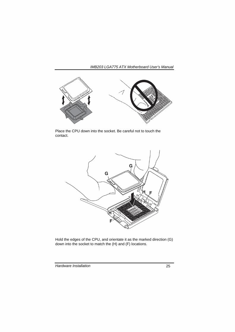
IMB203 LGA775 ATX Motherboard Userrsquos Manual
Hardware Installation 26
Slightly push down the cover and hook the lever (I~J) The CPU is completely locked
Orientate the CPU cooling fan to fixing holes on the board
IMB203 LGA775 ATX Motherboard Userrsquos Manual
Hardware Installation 27
Screw the CPU cooling fan onto the board
Make sure the CPU fan is plugged to the CPU fan connector
IMB203 LGA775 ATX Motherboard Userrsquos Manual
Hardware Installation 28
32 Installing the Memory The board supports four 240-pin DDR3 DIMM memory sockets with maximum memory capacity up to 16GB Please follow steps below to install the memory modules 1 Push down latches on each side of the DIMM socket 2 Align the memory module with the socket that notches of
memory module must match the socket keys for a correct installation
3 Install the memory module into the socket and push it firmly down until it is fully seated The socket latches are levered upwards and clipped on to the edges of the DIMM
4 Install any remaining DIMM modules
IMB203 LGA775 ATX Motherboard Userrsquos Manual
Hardware Description 29
CHAPTER 4 HARDWARE DESCRIPTION
41 Microprocessors The IMB203 Series supports Intelreg Coretrade 2 Quad Coretrade 2 Duo processors which make your system operated under Windowsreg XP and Linux environments The system performance depends on the microprocessor Make sure all correct settings are arranged for your installed microprocessor to prevent the CPU from damages
42 BIOS The IMB203 Series uses AMI Plug and Play BIOS with a single 32Mbit SPI Flash
43 System Memory The IMB203 Series supports four 240-pin DDR3 DIMM sockets for a maximum memory of 16GB DDR3 SDRAMs The memory module can come in sizes of 1GB 2GB and 4GB
IMB203 LGA775 ATX Motherboard Userrsquos Manual
Hardware Description 30
44 IO Port Address Map The Intelreg Coretrade 2 Extreme Intelreg Coretrade 2 Quad Coretrade 2 Duo CPUs can communicate via IO ports There are total 1KB port addresses available for assignment to other devices via IO expansion cards
Address Devices 000-01F DMA controller 1
020-02D 024-025 028-029 02C-02D Interrupt controller 1
02E-02F Forwarded to LPC(LPC Super IO ) 030-031 034-035 038-039 03C-03D
Interrupt controller 2
040-043 050-053 TimerCounter (8254) 060 Forwarded to LPC (Microcontroller) 061 NMI
062-066 Forwarded to LPC (Microcontroller) 070-077 Real time clock NMI 080-091 DMA page register
092 Processor IF(Reset Generator) 093-09F DMA page register 0A0-0BF Interrupt controller 2 0C0-0DF DMA controller 2
0F0 Processor IF 0F8-0FF Math processor 170-177 Forward to SATA (SATA Controller) 1F0-1F7 Forward to SATA (SATA Controller)
376 Forward to SATA(SATA Controller) 378-37F Parallel Port (LPT) 380-38F SDLC 2 3A0-3AF SDLC 1 3B0-3BF MDA video card
(to be continued)
IMB203 LGA775 ATX Motherboard Userrsquos Manual
Hardware Description 31
Address Devices 3C0-3CF EGA card 3D0-3DF CGA card
3F6 Forward to SATA(SATA Controller) 3F8-3FF Serial port 1 (COM1) 2F8-2FF Serial port 2 (COM2)
45 Interrupt Controller (IRQ) Map The IMB203 Series is a 100 PC compatible control board It consists of 16 interrupt request lines and four out of them can be programmable The mapping list of the 16 interrupt request lines is shown as the following table
IRQ Parity check error IRQ0 System Timer Output
IRQ1 Keyboard
IRQ2 Interrupt rerouting from IRQ8 through IRQ15
IRQ3 Serial port 2
IRQ4 Serial port 1
IRQ5 PCI Device Share
IRQ7 Parallel port
IRQ8 Real time clock
IRQ9 ACPI Controller
IRQ10 PCI Device Share
IRQ11 PCI Device Share
IRQ12 PS2 Mouse
IRQ13 Math coprocessor
IRQ14 SATA Primary (Legacy Mode)
IRQ15 SATA Secondary (Legacy Mode)
IMB203 LGA775 ATX Motherboard Userrsquos Manual
Hardware Description 32
MEMO
IMB203 LGA775 ATX Motherboard Userrsquos Manual
AMI BIOS Setup Utility 33
CHAPTER 5 AMI BIOS SETUP UTILITY
This chapter provides users with detailed description how to set up basic system configuration through the AMIBIOS8 BIOS setup utility 51 Starting To enter the setup screens follow the steps below 1 Turn on the computer and press the ltDelgt key immediately 2 After you press the ltDeletegt key the main BIOS setup menu
displays You can access the other setup screens from the main BIOS setup menu such as the Chipset and Power menus
52 Navigation Keys The BIOS setuputility uses a key-based navigation system called hot keys Most of the BIOS setup utility hot keys can be used at any time during the setup navigation process These keys include ltF1gt ltF10gt ltEntergt ltESCgt ltArrowgt keys and so on
Note Some of navigation keys differ from one screen to another
IMB203 LGA775 ATX Motherboard Userrsquos Manual
AMI BIOS Setup Utility 34
LeftRight The Left ltArrowgt keys allow you to select a setup screen
UpDown The Up and Down ltArrowgt keys allow you to select a setup screen or sub-screen
+minus PlusMinus The Plus and Minus ltArrowgt keys allow you to change the field value of a particular setup item
Tab The ltTabgt key allows you to select setup fields
F1 The ltF1gt key allows you to display the General Help screen
F10 The ltF10gt key allows you to save any changes you have made and exit Setup Press the ltF10gt key to save your changes
Esc
The ltEscgt key allows you to discard any changes you have made and exit the Setup Press the ltEscgt key to exit the setup without saving your changes
Enter
The ltEntergt key allows you to display or change the setup option listed for a particular setup item The ltEntergt key can also allow you to display the setup sub- screens
IMB203 LGA775 ATX Motherboard Userrsquos Manual
AMI BIOS Setup Utility 35
53 Main Menu When you first enter the Setup Utility you will enter the Main setup screen You can always return to the Main setup screen by selecting the Main tab There are two Main Setup options They are described in this section The Main BIOS Setup screen is shown below
System TimeDate
Use this option to change the system time and date Highlight System Time or System Date using the ltArrowgt keys Enter new values through the keyboard Press the ltTabgt key or the ltArrowgt keys to move between fields The date must be entered in MMDDYY format The time is entered in HHMMSS format
IMB203 LGA775 ATX Motherboard Userrsquos Manual
AMI BIOS Setup Utility 36
54 Advanced Menu The Advanced menu allows users to set configuration of the CPU and other system devices You can select any of the items in the left frame of the screen to go to the sub menus
CPU Configuration IDE Configuration SuperIO Configuration Hardware Health Configuration ACPI Configuration AHCI Configuration Intel iAMT Configuration Intel VT-d Configuration MPS Configuration PCI Express Configuration Trusted Computing USB Configuration
For items marked with ldquo rdquo please press ltEntergt for more options
IMB203 LGA775 ATX Motherboard Userrsquos Manual
AMI BIOS Setup Utility 37
CPU Configuration This screen shows the CPU Configuration and you can change the value of the selected option
Max CPUID Value Limit
You can enable this item to let legacy operating systems boot even without support for CPUs with extended CPU ID functions
Execute-Disable Bit Capability This item helps you enable or disable the No-Execution Page Protection Technology
Core Multi-Processing This feature controls the functionality of the Core Multi-Processing to allow the processor to execute multitasking function
PECI Use this item PECI (Platform Environment Control Interface) to execute the processor temperature monitoring and management
IMB203 LGA775 ATX Motherboard Userrsquos Manual
AMI BIOS Setup Utility 38
Intel (R) C-STATE tech Use this item to enable or disable the C-State technology
IDE Configuration You can use this screen to select options for the IDE Configuration and change the value of the selected option A description of the selected item appears on the right side of the screen For items marked with ldquo rdquo please press ltEntergt for more options
SATA1 Configuration
Use this item to control the onboard SATA controller Here are the options for your selection Compatible Disabled and Enhanced
Configure SATA1 as Use this item to choose the SATA operation mode Here are the options for your selection IDE and AHCI
SATA2 Configuration Use this item to control the onboard SATA controller Here are the options for your selection Enhanced and Disabled
IMB203 LGA775 ATX Motherboard Userrsquos Manual
AMI BIOS Setup Utility 39
PrimarySecondaryThird IDE Master Select one of the hard disk drives to configure IDE devices installed in the system by pressing ltEntergt for more options
Fifth IDE Master Select one of the hard disk drives to configure IDE devices installed in the system by pressing ltEntergt for more options
IMB203 LGA775 ATX Motherboard Userrsquos Manual
AMI BIOS Setup Utility 40
SuperIO Configuration You can use this screen to select options for the SuperIO Configuration and change the value of the selected option A description of the selected item appears on the right side of the screen
Serial Port1 Address
This option specifies the base IO port address and Interrupt Request address of serial port 1 The Optimal setting is 3F8IRQ4 The Fail-Safe default setting is Disabled
Serial Port2 Address This option specifies the base IO port address and Interrupt Request address of serial port 2 The Optimal setting is 2F8IRQ3 The Fail-Safe setting is Disabled
Parallel Port Address This item allows you to determine the IO address for onboard parallel port There are several options for your selection
Parallel Port Mode
IMB203 LGA775 ATX Motherboard Userrsquos Manual
AMI BIOS Setup Utility 41
Select an operating mode for the onboard parallel (printer) port
Parallel Port IRQ Use this item to set up the IRQ for onboard parallel port
Serial Port3 Address This item specifies the base IO port address and Interrupt Request address of serial port 3 The Optimal setting is 3E8IRQ11 The Fail-Safe default setting is Disabled
Serial Port3 IRQ This item specifies the IRQ used by the serial port 3
Serial Port4 Address This item specifies the base IO port address and Interrupt Request address of serial port 4 The Optimal setting is 2E8IRQ10 The Fail-Safe default setting is Disabled
Serial Port4 IRQ This item specifies the IRQ used by the serial port 4
IMB203 LGA775 ATX Motherboard Userrsquos Manual
AMI BIOS Setup Utility 42
Hardware Health Configuration This screen shows the Hardware Health Configuration and a description of the selected item appears on the right side of the screen
HW Health Configuration
This screen displays the temperature of CPU and System Fan Speed Vcore etc
IMB203 LGA775 ATX Motherboard Userrsquos Manual
AMI BIOS Setup Utility 43
ACPI Configuration You can use this screen to select options for the ACPI Configuration and change the value of the selected option A description of the selected item appears on the right side of the screen
General ACPI Configuration
Scroll to this item and press ltEntergt to view the General ACPI Configuration sub menu which contains General ACPI (Advanced Configuration and Power Management Interface) options for your configuration
Advanced ACPI Configuration Scroll to this item and press ltEntergt to view the Advanced ACPI Configuration sub menu which contains Advanced ACPI (Advanced Configuration and Power Management Interface) options for your configuration
Chipset ACPI Configuration Scroll to this item and press ltEntergt to view the Chipset ACPI Configuration sub menu which contains Chipset ACPI (Advanced Configuration and Power Management
IMB203 LGA775 ATX Motherboard Userrsquos Manual
AMI BIOS Setup Utility 44
Interface) options for your configuration AHCI Configuration
You can use this screen to select options for the AHCI Configuration and change the value of the selected option A description of the selected item appears on the right side of the screen
AHCI BIOS Support You can enable or disable this item to control the AHCI function of the SATA controller
IMB203 LGA775 ATX Motherboard Userrsquos Manual
AMI BIOS Setup Utility 45
Intel iAMT Configuration You can use this screen to select options for the Intel iAMT Configuration and change the value of the selected option A description of the selected item appears on the right side of the screen
Intel iAMT Support
You can enable this item to support iAMT (active management technology) function to follow up the procedure for the access to AMI program screen
Unconfigure iAMTME Use this item to unconfigure the iAMTME settings
IMB203 LGA775 ATX Motherboard Userrsquos Manual
AMI BIOS Setup Utility 46
Intel VT-d Configuration You can use this screen to select options for the Intel VT-d Configuration and change the value of the selected option A description of the selected item appears on the right side of the screen
Intel VT-d Virtualization Technology for Directed IO (VT-d) extends Virtualization Technology (VT) roadmap by providing hardware assists for virtualization solution VT-d can help end users improve security and reliability of the systems and also improve performance of IO devices in virtualized environment Here are the options for your selection Disabled and Enabled
IMB203 LGA775 ATX Motherboard Userrsquos Manual
AMI BIOS Setup Utility 47
Remote Access Configuration You can use this screen to select options for the Remote Access Configuration and change the value of the selected option A description of the selected item appears on the right side of the screen
Remote Access Use this item to enable or disable the Remote Access function
IMB203 LGA775 ATX Motherboard Userrsquos Manual
AMI BIOS Setup Utility 48
PCI Express Configuration This screen shows the PCI Express Configuration and you can change its value A description of the selected item appears on the right side of the screen
Active State Power-Management
Use this item to enable or disable the function of Active State Power-Management to provide you with lower power consumption The default setting is Disabled
IMB203 LGA775 ATX Motherboard Userrsquos Manual
AMI BIOS Setup Utility 49
Trusted Computing You can use this screen to select options for the Trusted Computing and change the value of the selected option A description of the selected item appears on the right side of the screen
TCGTPM SUPPORT Use this item to control the Trusted Platform Module (TPM) function
IMB203 LGA775 ATX Motherboard Userrsquos Manual
AMI BIOS Setup Utility 50
USB Configuration You can use this screen to select options for the USB Configuration and change the value of the selected option A description of the selected item appears on the right side of the screen
USB Functions
This item allows you to enable or disable USB functions
Legacy USB Support Use this item to enable or disable support for USB device on legacy operating system The default setting is Enabled
USB 20 Controller Mode Use this item to configure the USB 20 controller The default setting is HiSpeed
BIOS EHCI Hand-Off Enabling this item provide the support for operating systems without an EHCI hand-off feature The default setting is Enabled
IMB203 LGA775 ATX Motherboard Userrsquos Manual
AMI BIOS Setup Utility 51
IMB203 LGA775 ATX Motherboard Userrsquos Manual
AMI BIOS Setup Utility 52
55 PCI PnP Menu The PCI PnP menu allows users to change the advanced settings for PCIPnP devices
Clear NVRAM
Use this item to clear the data in the NVRAM (CMOS) Here are the options for your selection No and Yes
Plug amp Play OS When the setting is No Use this item to configure all the devices in the system When the setting is Yes and if you install a Plug and Play operating system the operating system configures the Plug and Play devices not required for boot The default setting is No
IMB203 LGA775 ATX Motherboard Userrsquos Manual
AMI BIOS Setup Utility 53
PCI Latency Timer This item controls how long a PCI device can hold the PCI bus before another takes over The longer the latency the longer the PCI device can retain control of the bus before handing it over to another PCI device There are several options for your selection
Allocate IRQ to PCI VGA This item allows BIOS to choose an IRQ to assign for the PCI VGA card Here are the options for your selection No and Yes
Palette Snooping Some old graphic controllers need to ldquosnooprdquo on the VGA palette and then map it to their display as a way to provide boot information and VGA compatibility This item allows such snooping to take place Here are the options for your selection Disabled and Enabled
PCI IDE BusMaster This item is a toggle for the built-in driver that allows the onboard IDE controller to perform DMA (Direct Memory Access) transfer Here are the options for your selection Disabled and Enabled
OffBoard PCIISA IDE Card This item is for any other non-onboard PCIISA IDE controller adapter There are several options for your selection
IRQ3457910111415 These items will allow you to assign each system interrupt a type depending on the type of device using the interrupt The option ldquoAvailablerdquo means the IRQ is going to assign automatically Here are the options for your selection Available and Reserved
DMA Channel 013567 These items will allow you to assign each DMA channel a type depending on the type of device using the channel The option ldquoAvailablerdquo means the channel is going to assign automatically Here are the options for your selection Available and Reserved
IMB203 LGA775 ATX Motherboard Userrsquos Manual
AMI BIOS Setup Utility 54
56 Boot Menu The Boot menu allows users to change boot options of the system You can select any of the items in the left frame of the screen to go to the sub menus
Boot Settings Configuration Boot Device Priority Removable Drives
For items marked with ldquo rdquo please press ltEntergt for more options
IMB203 LGA775 ATX Motherboard Userrsquos Manual
AMI BIOS Setup Utility 55
Boot Settings Configuration
Quick Boot
Enabling this item lets the BIOS skip some power on self tests (POST) The default setting is Enabled
AddOn ROM Display Mode This item selects the display mode for option ROM The default setting is Force BIOS
Boot Num-Lock Use this item to select the power-on state for the NumLock The default setting is On
PS2 Mouse Support This item determines if the BIOS should reserve IRQ12 for the PS2 mouse or allow other devices to make use of this IRQ Here are the options for your selection Auto Enabled and Disabled
Wait For lsquoF1rsquo Of Error If this item is enabled the system waits for the F1 key to be pressed when error occurs The default setting is Enabled
Hit lsquoDELrsquo Message Display If this item is enabled the system displays the message
IMB203 LGA775 ATX Motherboard Userrsquos Manual
AMI BIOS Setup Utility 56
ldquoPress DEL to run Setuprdquo during POST The default setting is Enabled
Interrupt 19 Capture If this item is enabled this function makes the option ROMs to trap Interrupt 19 The default setting is Disabled
Boot Device Priority The Boot Device Priority screen specifies the boot device priority sequence from the available devices
IMB203 LGA775 ATX Motherboard Userrsquos Manual
AMI BIOS Setup Utility 57
Removable Drives Use this screen to view the removable drives in the system The BIOS will attempt to arrange the removable drive boot sequence automatically You can also change the booting sequence
IMB203 LGA775 ATX Motherboard Userrsquos Manual
AMI BIOS Setup Utility 58
57 Security Menu The Security menu allows users to change the security settings for the system
Supervisor Password
This item indicates whether a supervisor password has been set If the password has been installed Installed displays If not Not Installed displays
User Password This item indicates whether a user password has been set If the password has been installed Installed displays If not Not Installed displays
Change Supervisor Password Select this option and press ltEntergt to access the sub menu You can use the sub menu to change the supervisor password
Change User Password Select this option and press ltEntergt to access the sub menu You can use the sub menu to change the user password
IMB203 LGA775 ATX Motherboard Userrsquos Manual
AMI BIOS Setup Utility 59
58 Chipset Menu The Chipset menu allows users to change the advanced chipset settings You can select any of the items in the left frame of the screen to go to the sub menus
North Bridge Configuration South Bridge Configuration ME Subsystem Configuration
For items marked with ldquo rdquo please press ltEntergt for more options
IMB203 LGA775 ATX Motherboard Userrsquos Manual
AMI BIOS Setup Utility 60
North Bridge Configuration
Memory Remap Feature
Use this item to enable or disable the remapping of the overlapped PCI memory above the total physical memory Only 64-bit OS supports this function
DRAM Frequency This item allows you to control the Memory Clock
Configure DRAM Timing by SPD This item can enable or disable DRAM timing by SPD (Serial Presence Detect) device which is a small EEPROM chip on the memory module containing important information about the module speed size addressing mode and various parameters
Memory Hole You can reserve this area of system memory for ISA adapter ROM When this area is reserved it cannot be cached Check the user information of peripherals that need to use this area o f system memory for the memory requirements Here are the options Disabled and 15M-16M
IMB203 LGA775 ATX Motherboard Userrsquos Manual
AMI BIOS Setup Utility 61
Initiate Graphic Adapter When using multiple graphics cards this item can select which graphics controller to be the primary display device during boot
IGD Graphics Mode Select This item allows you to select the amount of system memory used by the internal graphics device
PEG Port ConfigurationPEG Port This item is a toggle to enable or disable the PCI Express port Here are the options for your selection Auto and Disabled
Video Function Configuration Press ltEntergt for the sub-menu for setting up video function
IMB203 LGA775 ATX Motherboard Userrsquos Manual
AMI BIOS Setup Utility 62
South Bridge Configuration
GbE Wake Up From S5 This item specifies whether the system will be awakened from the S5 power
HDA Controller This item allows you to enable or disable the HD audio support
Restore on AC Power Loss This item can control how the PC will behave once power is restored following a power outage or other unexpected shutdown
PCIE Port Configuration This item allows you to set or disable the PCI Express Ports
IMB203 LGA775 ATX Motherboard Userrsquos Manual
AMI BIOS Setup Utility 63
ME Subsystem Configuration
It is strongly recommended that you do not modify these options unless you are an advanced user
IMB203 LGA775 ATX Motherboard Userrsquos Manual
AMI BIOS Setup Utility 64
59 Exit Menu The Exit menu allows users to load your system configuration with optimal or failsafe default values
Save Changes and Exit
When you have completed the system configuration changes select this option to leave Setup and reboot the computer so the new system configuration parameters can take effect Select Save Changes and Exit from the Exit menu and press ltEntergt Select Ok to save changes and exit
Discard Changes and Exit Select this option to quit Setup without making any permanent changes to the system configuration Select Discard Changes and Exit from the Exit menu and press ltEntergt Select Ok to discard changes and exit
Load Optimal Defaults It automatically sets all Setup options to a complete set of default settings when you select this option The Optimal settings are designed for maximum system performance but may not work best for all computer applications In particular do not use the Optimal Setup options if your
IMB203 LGA775 ATX Motherboard Userrsquos Manual
AMI BIOS Setup Utility 65
computer is experiencing system configuration problems Select Load Optimal Defaults from the Exit menu and press ltEntergt
Load Fail-Safe Defaults It automatically sets all Setup options to a complete set of default settings when you select this option The Fail-Safe settings are designed for maximum system stability but not maximum performance Select the Fail-Safe Setup options if your computer is experiencing system configuration problems Select Load Fail-Safe Defaults from the Exit menu and press ltEntergt Select Ok to load Fail-Safe defaults
IMB203 LGA775 ATX Motherboard Userrsquos Manual
AMI BIOS Setup Utility 66
MEMO
IMB203 LGA775 ATX Motherboard Userrsquos Manual
Installation of Drivers 67
CHPATER 6 INSTALLATION OF DRIVERS
The device drivers are located on the Product Information CD-ROM that comes with the IMB203 Series package The auto-run function of drivers will guide you to install the utilities and device drivers under a Windows system You can follow the onscreen instructions to install these devices
Chipse VGA LAN Audio iAMT MEI
61 Installing Chipset Driver 1 Run the SETUPEXE program from the driver directory in
your driver CD Click ldquoNextrdquo to next step
IMB203 LGA775 ATX Motherboard Userrsquos Manual
Installation of Drivers 68
2 An Intelreg License Agreement appears to show you the important information Click ldquoYesrdquo to next step
3 Refer to the Readme file below to view the system requirements and installation information
IMB203 LGA775 ATX Motherboard Userrsquos Manual
Installation of Drivers 69
3-1 Please wait while running the following setup operations
3-2 Please wait while running the following setup operations
IMB203 LGA775 ATX Motherboard Userrsquos Manual
Installation of Drivers 70
4 Click ldquoFinishrdquo to complete the setup process
5 You will be asked to reboot your computer when the installation is completed Please click ldquoYes I want to restart my computer nowrdquo if you donrsquot need to install any other drivers Otherwise please click ldquoNo I will restart my computer laterrdquo and go on next step
IMB203 LGA775 ATX Motherboard Userrsquos Manual
Installation of Drivers 71
62 Installing VGA Driver 1 Run the SETUPEXE program from the driver directory in
your driver CD Click ldquoNextrdquo to next step
2 An Intelreg License Agreement appears to show you the
important information Click ldquoYesrdquo to next step
IMB203 LGA775 ATX Motherboard Userrsquos Manual
Installation of Drivers 72
3 The message of Readme File Information appears to show you the system requirements and installation information Please click ldquoNextrdquo
4 Please wait while running the following setup operations
When this message appears please click ldquoNextrdquo
IMB203 LGA775 ATX Motherboard Userrsquos Manual
Installation of Drivers 73
5 Click ldquoFinishrdquo to complete the setup process
6 You will be asked to reboot your computer when the installation is completed Please click ldquoYes I want to restart my computer nowrdquo if you donrsquot need to install any other drivers Otherwise please click ldquoNo I will restart my computer laterrdquo and click ldquoFinishrdquo to complete the installation
IMB203 LGA775 ATX Motherboard Userrsquos Manual
Installation of Drivers 74
63 Installing LAN Driver
11 Run the InstallShield Wizard for Network Connections from
the driver directory in your driver CD Click ldquoNextrdquo to next step
IMB203 LGA775 ATX Motherboard Userrsquos Manual
Installation of Drivers 75
12 An Intelreg License Agreement appears to show you the important information Click ldquoYesrdquo to next step
13 A Setup Options window appears that you can select the
program features you want to install
IMB203 LGA775 ATX Motherboard Userrsquos Manual
Installation of Drivers 76
2 Click ldquoInstallrdquo to start the installation
3 Please wait while running the following installation operation
IMB203 LGA775 ATX Motherboard Userrsquos Manual
Installation of Drivers 77
4 Click ldquoFinishrdquo to complete the installation
Note The Driver item [Wake on Directed Packet] default is Enabled under Windows Vista
格式化 字型 (符號) Arial
格式化 字型 (符號) Arial
格式化 字型 斜體 字型色彩 黑色 (符號) Arial 非加寬 緊縮
格式化 字型 斜體 字型色彩 黑色 (符號) Arial 非加寬 緊縮
格式化 字型 (符號) Arial 非加寬 緊縮
IMB203 LGA775 ATX Motherboard Userrsquos Manual
Installation of Drivers 78
64 Installing AUDIO Driver 1 Run the InstallShield Wizard for Realtek High Definition
Audio Driver from the driver directory in your driver CD Click ldquoNextrdquo to next step
IMB203 LGA775 ATX Motherboard Userrsquos Manual
Installation of Drivers 79
2 Click ldquoInstallrdquo to start the installation and wait while running the installation operation
3 Click ldquoFinishrdquo to complete the installation
IMB203 LGA775 ATX Motherboard Userrsquos Manual
Installation of Drivers 80
65 Installing iAMT (Active Management Technology) Driver
Note You must download and properly install the required NET version 35 provided from a separate downloading of the actual FimwareTools kit releases posted on VIP prior to loading the MEILMS Driver stack
651 LMS_SOL Setup
1 Run the setup program to install Intelreg Active Management Technology onto your computer It is strongly recommended that you exit all programs before continuing Click ldquoNextrdquo to next step
格式化 字型 (符號) Arial
格式化 字型 (符號) Arial 非加寬 緊縮
IMB203 LGA775 ATX Motherboard Userrsquos Manual
Installation of Drivers 81
2 An Intelreg license agreement appears that you need to continue the setup program by clicking ldquoYesrdquo to accept the terms
IMB203 LGA775 ATX Motherboard Userrsquos Manual
Installation of Drivers 82
3 Refer to the Readme file below to view the system requirements and installation information Click ldquoNextrdquo to next setup
4 Please wait while running the following installation operation
IMB203 LGA775 ATX Motherboard Userrsquos Manual
Installation of Drivers 83
5 Click ldquoFinishrdquo to complete the installation
IMB203 LGA775 ATX Motherboard Userrsquos Manual
Installation of Drivers 84
652 LMS_SOL_IS Setup
1 Run the setup program to install Intelreg Active Management Technology onto your computer It is strongly recommended that you exit all programs before continuing Click ldquoNextrdquo to next step
IMB203 LGA775 ATX Motherboard Userrsquos Manual
Installation of Drivers 85
2 An Intelreg license agreement appears that you need to continue the setup program by clicking ldquoYesrdquo to accept the terms
IMB203 LGA775 ATX Motherboard Userrsquos Manual
Installation of Drivers 86
3 Refer to the Readme file below to view the system requirements and installation information Click ldquoNextrdquo to next setup
4 Please wait while running the following installation operation
IMB203 LGA775 ATX Motherboard Userrsquos Manual
Installation of Drivers 87
5 Click ldquoFinishrdquo to complete the installation
IMB203 LGA775 ATX Motherboard Userrsquos Manual
Installation of Drivers 88
66 Installing MEI (Management Engine Interface) Driver
Note You must download and properly install the required NET version 35 provided from a separate downloading of the actual FimwareTools kit releases posted on VIP prior to loading the MEILMS Driver stack
1 Run the setup program to install Intelreg Management Engine
Interface onto your computer It is strongly recommended that you exit all programs before continuing Click ldquoNextrdquo to next step
格式化 字型 (符號) Arial
格式化 字型 (符號) Arial 非加寬 緊縮
IMB203 LGA775 ATX Motherboard Userrsquos Manual
Installation of Drivers 89
2 An Intelreg license agreement appears that you need to continue the setup program by clicking ldquoYesrdquo to accept the terms
IMB203 LGA775 ATX Motherboard Userrsquos Manual
Installation of Drivers 90
3 Refer to the Readme file below to view the system requirements and installation information Click ldquoNextrdquo to next setup
4 Please wait while running the following installation operation
IMB203 LGA775 ATX Motherboard Userrsquos Manual
Installation of Drivers 91
5 Click ldquoFinishrdquo to complete the installation
IMB203 LGA775 ATX Motherboard Userrsquos Manual
Installation of Drivers 92
MEMO
IMB203 LGA775 ATX Motherboard Userrsquos Manual
Watchdog Timer 93
APPENDIX A WATCHDOG TIMER
Watchdog Timer Setting After the system stops working for a while it can be auto-reset by the Watchdog Timer The integrated Watchdog Timer can be set up in the system reset mode by program
Using the Watchdog Function Start darr Un-Lock WDT O 2E 87 Un-lock super IO
O 2E 87 Un-lock super IO darr Set WDT Function O 2E 2D O 2F 20 Select Logic device O 2E 07 O 2F 08 darr Activate WDT O 2E 30
O 2F 01 Set Second or Minute O 2E F5
O 2F N N=00 or 08(See below table) darr Set base timer O 2E F6
O 2F M=000102hellipFF(Hex) Value=0 to 255 darr WDT counting
re-set timer O 2E F6
O 2F M M=000102hellipFF(See below table) darr
格式化
格式化 項目符號及編號
格式化 項目符號及編號
格式化 字型 8 點 字型色彩黑色
格式化 字型 8 點 字型色彩黑色
格式化 定位點 1257 字元左 + 不在 1012 字元 + 1386字元
格式化 字型 8 點 字型色彩黑色
格式化 定位點 1257 字元左 + 不在 134 字元 + 1362字元
格式化 字型色彩 黑色
格式化 字型色彩 黑色
刪除
IMB203 LGA775 ATX Motherboard Userrsquos Manual
Watchdog Timer 94
IF No re-set timer WDT time-out generate RESET IF to disable WDT O 2E 30
O 2F 00 Can be disable at any time
N=00
M= 00h Time-out Disable 01h Time-out occurs after 1 second 02h Time-out occurs after 2 second 03h Time-out occurs after 3 second helliphelliphelliphelliphelliphelliphelliphelliphellip FFh Time-out occurs after 255 second
N=08
M= 00h Time-out Disable 01h Time-out occurs after 1 minute 02h Time-out occurs after 2 minutes 03h Time-out occurs after 3 minutes helliphelliphelliphelliphelliphelliphelliphelliphellip
FFh Time-out occurs after 255 minutes
格式化 字型色彩 黑色
格式化 字型色彩 黑色
IMB203 LGA775 ATX Motherboard Userrsquos Manual
PCI IRQ Routing 95
APPENDIX B PCI IRQ ROUTING
PICMG PCI IRQ Routing
Device ID Slot Int
PCI Slot 0 31 0 BCDA PCI Slot 1 30 1 CDAB PCI Slot 2 29 2 DABC PCI Slot 3 28 3 ABCD
IMB203 LGA775 ATX Motherboard Userrsquos Manual
PCI IRQ Routing 96
MEMO
IMB203 LGA775 ATX Motherboard Userrsquos Manual
Configuring SATA for RAID Function 97
APPENDIX C CONFIGURING SATA FOR RAID
FUNCTION
Configuring SATA Hard Drive(s) for RAID Function (Controller IntelregICH10DODO DH only) Please follow up the steps below to configure SATA hard drive(s) (1) Install SATA hard drive(s) in your system (2) Enter the BIOS Setup to configure SATA controller mode and boot
sequence (3) Configure RAID by the RAID BIOS (4) Install the SATA controller driver during the OS installation Before you begin the SATA configuration please prepare (a) Two SATA hard drives (to ensure optimal performance it is
recommended that you use two hard drives with identical model and capacity) If you do not want to create RAID with the SATA controller you may prepare only one hard drive
(b) An empty formatted floppy disk (c) Windows XP setup disk (1) Installing SATA hard drive(s) in your system
Connect one end of the SATA signal cable to the rear of the SATA hard drive and the other end to available SATA port(s) on the board Then connect the power connector of power supply to the hard drive
(2) Configuring SATA controller mode and boot sequence by the BIOS Setup You have to make sure whether the SATA controller is configured correctly by system BIOS Setup and set up BIOS boot sequence for the SATA hard drive(s)
IMB203 LGA775 ATX Motherboard Userrsquos Manual
Configuring SATA for RAID Function 98
(2)-1-1 Turn on your system and then press the Del button to enter BIOS Setup during running POST (Power-On Self Test) If you want to create RAID just go to the Advanced Settings menuIDE configuration select the Configure SATA1 as and press ltEntergt for more options
IMB203 LGA775 ATX Motherboard Userrsquos Manual
Configuring SATA for RAID Function 99
(2)-1-2 A list of options appears please select RAID
IMB203 LGA775 ATX Motherboard Userrsquos Manual
Configuring SATA for RAID Function 100
(2)-2 Set CDROM for First Boot Device under the Boot Settings menu to boot CD-ROM after system restarts
(2)-3 Save and exit the BIOS Setup
IMB203 LGA775 ATX Motherboard Userrsquos Manual
Configuring SATA for RAID Function 101
(3) Configuring RAID by the RAID BIOS Enter the RAID BIOS setup utility to configure a RAID array Skip this step and proceed to Section 4 if you do not want to create a RAID (3)-1 After the POST memory testing and before the operating
system booting a message Press ltCtrl-Igt to enter Configuration Utility shows up accordingly press ltCTRL+ Igt to enter the RAID BIOS setup utility
(3)-2 After you press ltCTRL+ Igt the Create RAID Volume screen will appear If you want to create a RAID array select the Create RAID Volume option in the Main Menu and press ENTER
IMB203 LGA775 ATX Motherboard Userrsquos Manual
Configuring SATA for RAID Function 102
(3)-3-1 After entering the CREATE VOLUME MENU screen you can type the disk array name with 1~16 letters (letters cannot be special characters) in the item ldquoNamerdquo
(3)-3-2 When finished press ENTER to select a RAID level There are three RAID levels RAID0 RAID1 and RAID5 amp RAID10 Select a RAID level and press ENTER
IMB203 LGA775 ATX Motherboard Userrsquos Manual
Configuring SATA for RAID Function 103
(3)-4 Set the stripe block size The KB is the standard unit of stripe block size The stripe block size can be 4KB to 128KB After the setting press ENTER for the array capacity
(3)-5 After setting all the items on the menu select Create Volume
and press ENTER to start creating the RAID array
IMB203 LGA775 ATX Motherboard Userrsquos Manual
Configuring SATA for RAID Function 104
(3)-6 When prompting the confirmation press ldquoYldquo to create this volume or ldquoNldquo to cancel the creation
After the creation is completed you can see detailed information about the RAID Array in the DISKVOLUME INFORMATION section including RAID mode disk block size disk name and disk capacity etc
IMB203 LGA775 ATX Motherboard Userrsquos Manual
Configuring SATA for RAID Function 105
Delete RAID Volume If you want to delete a RAID volume select the Delete RAID Volume option in Main Menu Press ENTER and follow on-screen instructions
Please press [ESC] to exit the RAID BIOS utility Now you can proceed to install a SATA driver controller and the operating system
IMB203 LGA775 ATX Motherboard Userrsquos Manual
Configuring SATA for RAID Function 106
(4) Making a SATA Driver Disk To install the operating system onto a serial ATA hard disk successfully you need to install the SATA controller driver during the OS installation Without the driver the hard disk may not be recognized during the Windows setup process First of all please format a blank floppy disk Secondly follow up these steps below to produce a SATA driver disk Users can insert the Driver CD and the formatted blank floppy disk in another system And then please copy all of file of the f6flpy32 folder in the Driver CD to a floppy disk Note Please copy all of file of the f6flpy64 folder if installing 64-bit
Windows Operating System
IMB203 LGA775 ATX Motherboard Userrsquos Manual
Configuring SATA for RAID Function 107
(5) Installing the SATA controller driver during the OS installation Now the SATA driver disk is ready and BIOS settings configured you can proceed to install Windows 2000XP onto your SATA hard drive using the SATA driver Here is an example for Windows XP installation (5)-1 Restart your system to boot the Windows 2000XP Setup disk
and press F6 button as soon as you see the message Press F6 if you need to install a 3rd party SCSI or RAID driver After pressing the F6 button there will be a few moments for some files being loaded before next screen appears
IMB203 LGA775 ATX Motherboard Userrsquos Manual
Configuring SATA for RAID Function 108
(5)-2 When you see the screen below insert the floppy disk containing the SATA driver and press ldquoSrdquo
(5)-3 If the Setup correctly recognizes the driver of the floppy disk
a controller menu will appear below Use the ARROW keys to select Intel(R) ICH8RICH9RICH10RDO SATA RAID Controller and press ENTER Then it will begin to load the SATA driver from the floppy disk
IMB203 LGA775 ATX Motherboard Userrsquos Manual
Configuring SATA for RAID Function 109
Note If a message on the screen saying that one or some file(s) cannot be found please check the floppy disk or copy the correct SATA driver again from the driver CD
IMB203 LGA775 ATX Motherboard Userrsquos Manual
Configuring SATA for RAID Function 110
MEMO
IMB203 LGA775 ATX Motherboard Userrsquos Manual
iAMT Settings 111
APPENDIX D iAMT SETTINGS
The Intelreg Active Management Technology (Intelreg iAMT) has decreased a major barrier to IT efficiency that uses built-in platform capabilities and popular third-party management and security applications to allow IT a better discovering healing and protection their networked computing assets In order to utilize Intel iAMT you must enter the ME BIOS (CTRL + P during system startup) change the ME BIOS password and then select ldquoIntelreg iAMTrdquo as the manageability feature
D1 Entering MEBx 1 You must go to BIOS TO start iAMT function 2 Exit from BIOS after starting iAMT and press Ctrl+P to enter MEBx Setting
It is better to press Ctrl+P before the screen popping out
格式化
IMB203 LGA775 ATX Motherboard Userrsquos Manual
iAMT Settings 112
D2 Set amp Change Password 1 You will be asked to set a password when first log in The default
password is lsquoadminrsquo
2 You will be asked to change the password before setting ME
Change Password
IMB203 LGA775 ATX Motherboard Userrsquos Manual
iAMT Settings 113
3 You must confirm your new password while revising (as Remark 1)
Remark 1 The new password must contain (example 11qqQQ) (default value)
Eight characters
One upper case
One lower case
One number
One special symbol such as $ or
( excepted)
Underline ( _ ) and space are valid characters for password but they wonrsquot make higher complexity
IMB203 LGA775 ATX Motherboard Userrsquos Manual
iAMT Settings 114
D3 Intelreg iAMT Settings 1 Select Intelreg iAMT Configuration and press ltENTERgt
2 Key in the Host Name If Intelreg iAMT set to lsquoDHCPlsquo the Host name must be identical to the operating system mechanic
IMB203 LGA775 ATX Motherboard Userrsquos Manual
iAMT Settings 115
3 Select TCPIP to get into Network interface and set it to lsquoENABLEDrsquo into DHCP Mode and set it to lsquoDISABLEDrsquo (as Remark 2) into Domain name and set the Intel Management Engine domain name such as lsquoAMTintelcomrsquo
(3-1)
(3-2)
IMB203 LGA775 ATX Motherboard Userrsquos Manual
iAMT Settings 116
Remark 2 DHCP Mode lsquoDISABLEDlsquo if DHCP Mode is disabled you can make the following settings
IP address
Subnet mask
IMB203 LGA775 ATX Motherboard Userrsquos Manual
iAMT Settings 117
Default Gateway address
Preferred DNS address
IMB203 LGA775 ATX Motherboard Userrsquos Manual
iAMT Settings 118
Alternate DNS address
Domain name
4 Exit from MEBx after completing the iAMT settings
IMB203 LGA775 ATX Motherboard Userrsquos Manual
iAMT Settings 119
D4 iAMT Web Console 1 From a web browser please type http(IP ADDRESS)16992
which connects to iAMT Web Example http1014021416992
2 To log on you will be required to type in username and password
for access to the Web
USER admin (default value)
PASS (MEBx password)
IMB203 LGA775 ATX Motherboard Userrsquos Manual
iAMT Settings 120
3 Enter the iAMT Web
4 Click Remote Control and select commands on the right side
IMB203 LGA775 ATX Motherboard Userrsquos Manual
iAMT Settings 121
5 When you have finished using the iAMT Web console close the Web browser
IMB203 LGA775 ATX Motherboard Userrsquos Manual
iAMT Settings 122
MEMO
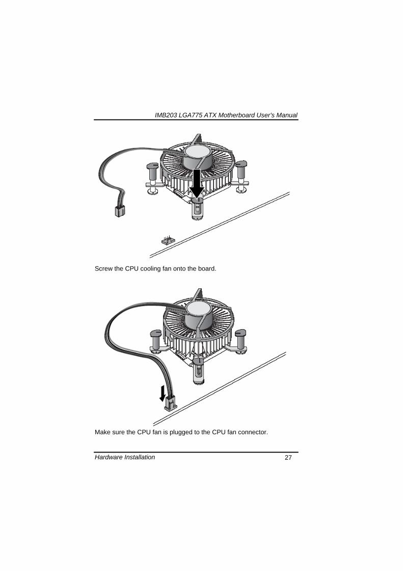
IMB203 LGA775 ATX Motherboard Userrsquos Manual
Hardware Installation 27
Screw the CPU cooling fan onto the board
Make sure the CPU fan is plugged to the CPU fan connector
IMB203 LGA775 ATX Motherboard Userrsquos Manual
Hardware Installation 28
32 Installing the Memory The board supports four 240-pin DDR3 DIMM memory sockets with maximum memory capacity up to 16GB Please follow steps below to install the memory modules 1 Push down latches on each side of the DIMM socket 2 Align the memory module with the socket that notches of
memory module must match the socket keys for a correct installation
3 Install the memory module into the socket and push it firmly down until it is fully seated The socket latches are levered upwards and clipped on to the edges of the DIMM
4 Install any remaining DIMM modules
IMB203 LGA775 ATX Motherboard Userrsquos Manual
Hardware Description 29
CHAPTER 4 HARDWARE DESCRIPTION
41 Microprocessors The IMB203 Series supports Intelreg Coretrade 2 Quad Coretrade 2 Duo processors which make your system operated under Windowsreg XP and Linux environments The system performance depends on the microprocessor Make sure all correct settings are arranged for your installed microprocessor to prevent the CPU from damages
42 BIOS The IMB203 Series uses AMI Plug and Play BIOS with a single 32Mbit SPI Flash
43 System Memory The IMB203 Series supports four 240-pin DDR3 DIMM sockets for a maximum memory of 16GB DDR3 SDRAMs The memory module can come in sizes of 1GB 2GB and 4GB
IMB203 LGA775 ATX Motherboard Userrsquos Manual
Hardware Description 30
44 IO Port Address Map The Intelreg Coretrade 2 Extreme Intelreg Coretrade 2 Quad Coretrade 2 Duo CPUs can communicate via IO ports There are total 1KB port addresses available for assignment to other devices via IO expansion cards
Address Devices 000-01F DMA controller 1
020-02D 024-025 028-029 02C-02D Interrupt controller 1
02E-02F Forwarded to LPC(LPC Super IO ) 030-031 034-035 038-039 03C-03D
Interrupt controller 2
040-043 050-053 TimerCounter (8254) 060 Forwarded to LPC (Microcontroller) 061 NMI
062-066 Forwarded to LPC (Microcontroller) 070-077 Real time clock NMI 080-091 DMA page register
092 Processor IF(Reset Generator) 093-09F DMA page register 0A0-0BF Interrupt controller 2 0C0-0DF DMA controller 2
0F0 Processor IF 0F8-0FF Math processor 170-177 Forward to SATA (SATA Controller) 1F0-1F7 Forward to SATA (SATA Controller)
376 Forward to SATA(SATA Controller) 378-37F Parallel Port (LPT) 380-38F SDLC 2 3A0-3AF SDLC 1 3B0-3BF MDA video card
(to be continued)
IMB203 LGA775 ATX Motherboard Userrsquos Manual
Hardware Description 31
Address Devices 3C0-3CF EGA card 3D0-3DF CGA card
3F6 Forward to SATA(SATA Controller) 3F8-3FF Serial port 1 (COM1) 2F8-2FF Serial port 2 (COM2)
45 Interrupt Controller (IRQ) Map The IMB203 Series is a 100 PC compatible control board It consists of 16 interrupt request lines and four out of them can be programmable The mapping list of the 16 interrupt request lines is shown as the following table
IRQ Parity check error IRQ0 System Timer Output
IRQ1 Keyboard
IRQ2 Interrupt rerouting from IRQ8 through IRQ15
IRQ3 Serial port 2
IRQ4 Serial port 1
IRQ5 PCI Device Share
IRQ7 Parallel port
IRQ8 Real time clock
IRQ9 ACPI Controller
IRQ10 PCI Device Share
IRQ11 PCI Device Share
IRQ12 PS2 Mouse
IRQ13 Math coprocessor
IRQ14 SATA Primary (Legacy Mode)
IRQ15 SATA Secondary (Legacy Mode)
IMB203 LGA775 ATX Motherboard Userrsquos Manual
Hardware Description 32
MEMO
IMB203 LGA775 ATX Motherboard Userrsquos Manual
AMI BIOS Setup Utility 33
CHAPTER 5 AMI BIOS SETUP UTILITY
This chapter provides users with detailed description how to set up basic system configuration through the AMIBIOS8 BIOS setup utility 51 Starting To enter the setup screens follow the steps below 1 Turn on the computer and press the ltDelgt key immediately 2 After you press the ltDeletegt key the main BIOS setup menu
displays You can access the other setup screens from the main BIOS setup menu such as the Chipset and Power menus
52 Navigation Keys The BIOS setuputility uses a key-based navigation system called hot keys Most of the BIOS setup utility hot keys can be used at any time during the setup navigation process These keys include ltF1gt ltF10gt ltEntergt ltESCgt ltArrowgt keys and so on
Note Some of navigation keys differ from one screen to another
IMB203 LGA775 ATX Motherboard Userrsquos Manual
AMI BIOS Setup Utility 34
LeftRight The Left ltArrowgt keys allow you to select a setup screen
UpDown The Up and Down ltArrowgt keys allow you to select a setup screen or sub-screen
+minus PlusMinus The Plus and Minus ltArrowgt keys allow you to change the field value of a particular setup item
Tab The ltTabgt key allows you to select setup fields
F1 The ltF1gt key allows you to display the General Help screen
F10 The ltF10gt key allows you to save any changes you have made and exit Setup Press the ltF10gt key to save your changes
Esc
The ltEscgt key allows you to discard any changes you have made and exit the Setup Press the ltEscgt key to exit the setup without saving your changes
Enter
The ltEntergt key allows you to display or change the setup option listed for a particular setup item The ltEntergt key can also allow you to display the setup sub- screens
IMB203 LGA775 ATX Motherboard Userrsquos Manual
AMI BIOS Setup Utility 35
53 Main Menu When you first enter the Setup Utility you will enter the Main setup screen You can always return to the Main setup screen by selecting the Main tab There are two Main Setup options They are described in this section The Main BIOS Setup screen is shown below
System TimeDate
Use this option to change the system time and date Highlight System Time or System Date using the ltArrowgt keys Enter new values through the keyboard Press the ltTabgt key or the ltArrowgt keys to move between fields The date must be entered in MMDDYY format The time is entered in HHMMSS format
IMB203 LGA775 ATX Motherboard Userrsquos Manual
AMI BIOS Setup Utility 36
54 Advanced Menu The Advanced menu allows users to set configuration of the CPU and other system devices You can select any of the items in the left frame of the screen to go to the sub menus
CPU Configuration IDE Configuration SuperIO Configuration Hardware Health Configuration ACPI Configuration AHCI Configuration Intel iAMT Configuration Intel VT-d Configuration MPS Configuration PCI Express Configuration Trusted Computing USB Configuration
For items marked with ldquo rdquo please press ltEntergt for more options
IMB203 LGA775 ATX Motherboard Userrsquos Manual
AMI BIOS Setup Utility 37
CPU Configuration This screen shows the CPU Configuration and you can change the value of the selected option
Max CPUID Value Limit
You can enable this item to let legacy operating systems boot even without support for CPUs with extended CPU ID functions
Execute-Disable Bit Capability This item helps you enable or disable the No-Execution Page Protection Technology
Core Multi-Processing This feature controls the functionality of the Core Multi-Processing to allow the processor to execute multitasking function
PECI Use this item PECI (Platform Environment Control Interface) to execute the processor temperature monitoring and management
IMB203 LGA775 ATX Motherboard Userrsquos Manual
AMI BIOS Setup Utility 38
Intel (R) C-STATE tech Use this item to enable or disable the C-State technology
IDE Configuration You can use this screen to select options for the IDE Configuration and change the value of the selected option A description of the selected item appears on the right side of the screen For items marked with ldquo rdquo please press ltEntergt for more options
SATA1 Configuration
Use this item to control the onboard SATA controller Here are the options for your selection Compatible Disabled and Enhanced
Configure SATA1 as Use this item to choose the SATA operation mode Here are the options for your selection IDE and AHCI
SATA2 Configuration Use this item to control the onboard SATA controller Here are the options for your selection Enhanced and Disabled
IMB203 LGA775 ATX Motherboard Userrsquos Manual
AMI BIOS Setup Utility 39
PrimarySecondaryThird IDE Master Select one of the hard disk drives to configure IDE devices installed in the system by pressing ltEntergt for more options
Fifth IDE Master Select one of the hard disk drives to configure IDE devices installed in the system by pressing ltEntergt for more options
IMB203 LGA775 ATX Motherboard Userrsquos Manual
AMI BIOS Setup Utility 40
SuperIO Configuration You can use this screen to select options for the SuperIO Configuration and change the value of the selected option A description of the selected item appears on the right side of the screen
Serial Port1 Address
This option specifies the base IO port address and Interrupt Request address of serial port 1 The Optimal setting is 3F8IRQ4 The Fail-Safe default setting is Disabled
Serial Port2 Address This option specifies the base IO port address and Interrupt Request address of serial port 2 The Optimal setting is 2F8IRQ3 The Fail-Safe setting is Disabled
Parallel Port Address This item allows you to determine the IO address for onboard parallel port There are several options for your selection
Parallel Port Mode
IMB203 LGA775 ATX Motherboard Userrsquos Manual
AMI BIOS Setup Utility 41
Select an operating mode for the onboard parallel (printer) port
Parallel Port IRQ Use this item to set up the IRQ for onboard parallel port
Serial Port3 Address This item specifies the base IO port address and Interrupt Request address of serial port 3 The Optimal setting is 3E8IRQ11 The Fail-Safe default setting is Disabled
Serial Port3 IRQ This item specifies the IRQ used by the serial port 3
Serial Port4 Address This item specifies the base IO port address and Interrupt Request address of serial port 4 The Optimal setting is 2E8IRQ10 The Fail-Safe default setting is Disabled
Serial Port4 IRQ This item specifies the IRQ used by the serial port 4
IMB203 LGA775 ATX Motherboard Userrsquos Manual
AMI BIOS Setup Utility 42
Hardware Health Configuration This screen shows the Hardware Health Configuration and a description of the selected item appears on the right side of the screen
HW Health Configuration
This screen displays the temperature of CPU and System Fan Speed Vcore etc
IMB203 LGA775 ATX Motherboard Userrsquos Manual
AMI BIOS Setup Utility 43
ACPI Configuration You can use this screen to select options for the ACPI Configuration and change the value of the selected option A description of the selected item appears on the right side of the screen
General ACPI Configuration
Scroll to this item and press ltEntergt to view the General ACPI Configuration sub menu which contains General ACPI (Advanced Configuration and Power Management Interface) options for your configuration
Advanced ACPI Configuration Scroll to this item and press ltEntergt to view the Advanced ACPI Configuration sub menu which contains Advanced ACPI (Advanced Configuration and Power Management Interface) options for your configuration
Chipset ACPI Configuration Scroll to this item and press ltEntergt to view the Chipset ACPI Configuration sub menu which contains Chipset ACPI (Advanced Configuration and Power Management
IMB203 LGA775 ATX Motherboard Userrsquos Manual
AMI BIOS Setup Utility 44
Interface) options for your configuration AHCI Configuration
You can use this screen to select options for the AHCI Configuration and change the value of the selected option A description of the selected item appears on the right side of the screen
AHCI BIOS Support You can enable or disable this item to control the AHCI function of the SATA controller
IMB203 LGA775 ATX Motherboard Userrsquos Manual
AMI BIOS Setup Utility 45
Intel iAMT Configuration You can use this screen to select options for the Intel iAMT Configuration and change the value of the selected option A description of the selected item appears on the right side of the screen
Intel iAMT Support
You can enable this item to support iAMT (active management technology) function to follow up the procedure for the access to AMI program screen
Unconfigure iAMTME Use this item to unconfigure the iAMTME settings
IMB203 LGA775 ATX Motherboard Userrsquos Manual
AMI BIOS Setup Utility 46
Intel VT-d Configuration You can use this screen to select options for the Intel VT-d Configuration and change the value of the selected option A description of the selected item appears on the right side of the screen
Intel VT-d Virtualization Technology for Directed IO (VT-d) extends Virtualization Technology (VT) roadmap by providing hardware assists for virtualization solution VT-d can help end users improve security and reliability of the systems and also improve performance of IO devices in virtualized environment Here are the options for your selection Disabled and Enabled
IMB203 LGA775 ATX Motherboard Userrsquos Manual
AMI BIOS Setup Utility 47
Remote Access Configuration You can use this screen to select options for the Remote Access Configuration and change the value of the selected option A description of the selected item appears on the right side of the screen
Remote Access Use this item to enable or disable the Remote Access function
IMB203 LGA775 ATX Motherboard Userrsquos Manual
AMI BIOS Setup Utility 48
PCI Express Configuration This screen shows the PCI Express Configuration and you can change its value A description of the selected item appears on the right side of the screen
Active State Power-Management
Use this item to enable or disable the function of Active State Power-Management to provide you with lower power consumption The default setting is Disabled
IMB203 LGA775 ATX Motherboard Userrsquos Manual
AMI BIOS Setup Utility 49
Trusted Computing You can use this screen to select options for the Trusted Computing and change the value of the selected option A description of the selected item appears on the right side of the screen
TCGTPM SUPPORT Use this item to control the Trusted Platform Module (TPM) function
IMB203 LGA775 ATX Motherboard Userrsquos Manual
AMI BIOS Setup Utility 50
USB Configuration You can use this screen to select options for the USB Configuration and change the value of the selected option A description of the selected item appears on the right side of the screen
USB Functions
This item allows you to enable or disable USB functions
Legacy USB Support Use this item to enable or disable support for USB device on legacy operating system The default setting is Enabled
USB 20 Controller Mode Use this item to configure the USB 20 controller The default setting is HiSpeed
BIOS EHCI Hand-Off Enabling this item provide the support for operating systems without an EHCI hand-off feature The default setting is Enabled
IMB203 LGA775 ATX Motherboard Userrsquos Manual
AMI BIOS Setup Utility 51
IMB203 LGA775 ATX Motherboard Userrsquos Manual
AMI BIOS Setup Utility 52
55 PCI PnP Menu The PCI PnP menu allows users to change the advanced settings for PCIPnP devices
Clear NVRAM
Use this item to clear the data in the NVRAM (CMOS) Here are the options for your selection No and Yes
Plug amp Play OS When the setting is No Use this item to configure all the devices in the system When the setting is Yes and if you install a Plug and Play operating system the operating system configures the Plug and Play devices not required for boot The default setting is No
IMB203 LGA775 ATX Motherboard Userrsquos Manual
AMI BIOS Setup Utility 53
PCI Latency Timer This item controls how long a PCI device can hold the PCI bus before another takes over The longer the latency the longer the PCI device can retain control of the bus before handing it over to another PCI device There are several options for your selection
Allocate IRQ to PCI VGA This item allows BIOS to choose an IRQ to assign for the PCI VGA card Here are the options for your selection No and Yes
Palette Snooping Some old graphic controllers need to ldquosnooprdquo on the VGA palette and then map it to their display as a way to provide boot information and VGA compatibility This item allows such snooping to take place Here are the options for your selection Disabled and Enabled
PCI IDE BusMaster This item is a toggle for the built-in driver that allows the onboard IDE controller to perform DMA (Direct Memory Access) transfer Here are the options for your selection Disabled and Enabled
OffBoard PCIISA IDE Card This item is for any other non-onboard PCIISA IDE controller adapter There are several options for your selection
IRQ3457910111415 These items will allow you to assign each system interrupt a type depending on the type of device using the interrupt The option ldquoAvailablerdquo means the IRQ is going to assign automatically Here are the options for your selection Available and Reserved
DMA Channel 013567 These items will allow you to assign each DMA channel a type depending on the type of device using the channel The option ldquoAvailablerdquo means the channel is going to assign automatically Here are the options for your selection Available and Reserved
IMB203 LGA775 ATX Motherboard Userrsquos Manual
AMI BIOS Setup Utility 54
56 Boot Menu The Boot menu allows users to change boot options of the system You can select any of the items in the left frame of the screen to go to the sub menus
Boot Settings Configuration Boot Device Priority Removable Drives
For items marked with ldquo rdquo please press ltEntergt for more options
IMB203 LGA775 ATX Motherboard Userrsquos Manual
AMI BIOS Setup Utility 55
Boot Settings Configuration
Quick Boot
Enabling this item lets the BIOS skip some power on self tests (POST) The default setting is Enabled
AddOn ROM Display Mode This item selects the display mode for option ROM The default setting is Force BIOS
Boot Num-Lock Use this item to select the power-on state for the NumLock The default setting is On
PS2 Mouse Support This item determines if the BIOS should reserve IRQ12 for the PS2 mouse or allow other devices to make use of this IRQ Here are the options for your selection Auto Enabled and Disabled
Wait For lsquoF1rsquo Of Error If this item is enabled the system waits for the F1 key to be pressed when error occurs The default setting is Enabled
Hit lsquoDELrsquo Message Display If this item is enabled the system displays the message
IMB203 LGA775 ATX Motherboard Userrsquos Manual
AMI BIOS Setup Utility 56
ldquoPress DEL to run Setuprdquo during POST The default setting is Enabled
Interrupt 19 Capture If this item is enabled this function makes the option ROMs to trap Interrupt 19 The default setting is Disabled
Boot Device Priority The Boot Device Priority screen specifies the boot device priority sequence from the available devices
IMB203 LGA775 ATX Motherboard Userrsquos Manual
AMI BIOS Setup Utility 57
Removable Drives Use this screen to view the removable drives in the system The BIOS will attempt to arrange the removable drive boot sequence automatically You can also change the booting sequence
IMB203 LGA775 ATX Motherboard Userrsquos Manual
AMI BIOS Setup Utility 58
57 Security Menu The Security menu allows users to change the security settings for the system
Supervisor Password
This item indicates whether a supervisor password has been set If the password has been installed Installed displays If not Not Installed displays
User Password This item indicates whether a user password has been set If the password has been installed Installed displays If not Not Installed displays
Change Supervisor Password Select this option and press ltEntergt to access the sub menu You can use the sub menu to change the supervisor password
Change User Password Select this option and press ltEntergt to access the sub menu You can use the sub menu to change the user password
IMB203 LGA775 ATX Motherboard Userrsquos Manual
AMI BIOS Setup Utility 59
58 Chipset Menu The Chipset menu allows users to change the advanced chipset settings You can select any of the items in the left frame of the screen to go to the sub menus
North Bridge Configuration South Bridge Configuration ME Subsystem Configuration
For items marked with ldquo rdquo please press ltEntergt for more options
IMB203 LGA775 ATX Motherboard Userrsquos Manual
AMI BIOS Setup Utility 60
North Bridge Configuration
Memory Remap Feature
Use this item to enable or disable the remapping of the overlapped PCI memory above the total physical memory Only 64-bit OS supports this function
DRAM Frequency This item allows you to control the Memory Clock
Configure DRAM Timing by SPD This item can enable or disable DRAM timing by SPD (Serial Presence Detect) device which is a small EEPROM chip on the memory module containing important information about the module speed size addressing mode and various parameters
Memory Hole You can reserve this area of system memory for ISA adapter ROM When this area is reserved it cannot be cached Check the user information of peripherals that need to use this area o f system memory for the memory requirements Here are the options Disabled and 15M-16M
IMB203 LGA775 ATX Motherboard Userrsquos Manual
AMI BIOS Setup Utility 61
Initiate Graphic Adapter When using multiple graphics cards this item can select which graphics controller to be the primary display device during boot
IGD Graphics Mode Select This item allows you to select the amount of system memory used by the internal graphics device
PEG Port ConfigurationPEG Port This item is a toggle to enable or disable the PCI Express port Here are the options for your selection Auto and Disabled
Video Function Configuration Press ltEntergt for the sub-menu for setting up video function
IMB203 LGA775 ATX Motherboard Userrsquos Manual
AMI BIOS Setup Utility 62
South Bridge Configuration
GbE Wake Up From S5 This item specifies whether the system will be awakened from the S5 power
HDA Controller This item allows you to enable or disable the HD audio support
Restore on AC Power Loss This item can control how the PC will behave once power is restored following a power outage or other unexpected shutdown
PCIE Port Configuration This item allows you to set or disable the PCI Express Ports
IMB203 LGA775 ATX Motherboard Userrsquos Manual
AMI BIOS Setup Utility 63
ME Subsystem Configuration
It is strongly recommended that you do not modify these options unless you are an advanced user
IMB203 LGA775 ATX Motherboard Userrsquos Manual
AMI BIOS Setup Utility 64
59 Exit Menu The Exit menu allows users to load your system configuration with optimal or failsafe default values
Save Changes and Exit
When you have completed the system configuration changes select this option to leave Setup and reboot the computer so the new system configuration parameters can take effect Select Save Changes and Exit from the Exit menu and press ltEntergt Select Ok to save changes and exit
Discard Changes and Exit Select this option to quit Setup without making any permanent changes to the system configuration Select Discard Changes and Exit from the Exit menu and press ltEntergt Select Ok to discard changes and exit
Load Optimal Defaults It automatically sets all Setup options to a complete set of default settings when you select this option The Optimal settings are designed for maximum system performance but may not work best for all computer applications In particular do not use the Optimal Setup options if your
IMB203 LGA775 ATX Motherboard Userrsquos Manual
AMI BIOS Setup Utility 65
computer is experiencing system configuration problems Select Load Optimal Defaults from the Exit menu and press ltEntergt
Load Fail-Safe Defaults It automatically sets all Setup options to a complete set of default settings when you select this option The Fail-Safe settings are designed for maximum system stability but not maximum performance Select the Fail-Safe Setup options if your computer is experiencing system configuration problems Select Load Fail-Safe Defaults from the Exit menu and press ltEntergt Select Ok to load Fail-Safe defaults
IMB203 LGA775 ATX Motherboard Userrsquos Manual
AMI BIOS Setup Utility 66
MEMO
IMB203 LGA775 ATX Motherboard Userrsquos Manual
Installation of Drivers 67
CHPATER 6 INSTALLATION OF DRIVERS
The device drivers are located on the Product Information CD-ROM that comes with the IMB203 Series package The auto-run function of drivers will guide you to install the utilities and device drivers under a Windows system You can follow the onscreen instructions to install these devices
Chipse VGA LAN Audio iAMT MEI
61 Installing Chipset Driver 1 Run the SETUPEXE program from the driver directory in
your driver CD Click ldquoNextrdquo to next step
IMB203 LGA775 ATX Motherboard Userrsquos Manual
Installation of Drivers 68
2 An Intelreg License Agreement appears to show you the important information Click ldquoYesrdquo to next step
3 Refer to the Readme file below to view the system requirements and installation information
IMB203 LGA775 ATX Motherboard Userrsquos Manual
Installation of Drivers 69
3-1 Please wait while running the following setup operations
3-2 Please wait while running the following setup operations
IMB203 LGA775 ATX Motherboard Userrsquos Manual
Installation of Drivers 70
4 Click ldquoFinishrdquo to complete the setup process
5 You will be asked to reboot your computer when the installation is completed Please click ldquoYes I want to restart my computer nowrdquo if you donrsquot need to install any other drivers Otherwise please click ldquoNo I will restart my computer laterrdquo and go on next step
IMB203 LGA775 ATX Motherboard Userrsquos Manual
Installation of Drivers 71
62 Installing VGA Driver 1 Run the SETUPEXE program from the driver directory in
your driver CD Click ldquoNextrdquo to next step
2 An Intelreg License Agreement appears to show you the
important information Click ldquoYesrdquo to next step
IMB203 LGA775 ATX Motherboard Userrsquos Manual
Installation of Drivers 72
3 The message of Readme File Information appears to show you the system requirements and installation information Please click ldquoNextrdquo
4 Please wait while running the following setup operations
When this message appears please click ldquoNextrdquo
IMB203 LGA775 ATX Motherboard Userrsquos Manual
Installation of Drivers 73
5 Click ldquoFinishrdquo to complete the setup process
6 You will be asked to reboot your computer when the installation is completed Please click ldquoYes I want to restart my computer nowrdquo if you donrsquot need to install any other drivers Otherwise please click ldquoNo I will restart my computer laterrdquo and click ldquoFinishrdquo to complete the installation
IMB203 LGA775 ATX Motherboard Userrsquos Manual
Installation of Drivers 74
63 Installing LAN Driver
11 Run the InstallShield Wizard for Network Connections from
the driver directory in your driver CD Click ldquoNextrdquo to next step
IMB203 LGA775 ATX Motherboard Userrsquos Manual
Installation of Drivers 75
12 An Intelreg License Agreement appears to show you the important information Click ldquoYesrdquo to next step
13 A Setup Options window appears that you can select the
program features you want to install
IMB203 LGA775 ATX Motherboard Userrsquos Manual
Installation of Drivers 76
2 Click ldquoInstallrdquo to start the installation
3 Please wait while running the following installation operation
IMB203 LGA775 ATX Motherboard Userrsquos Manual
Installation of Drivers 77
4 Click ldquoFinishrdquo to complete the installation
Note The Driver item [Wake on Directed Packet] default is Enabled under Windows Vista
格式化 字型 (符號) Arial
格式化 字型 (符號) Arial
格式化 字型 斜體 字型色彩 黑色 (符號) Arial 非加寬 緊縮
格式化 字型 斜體 字型色彩 黑色 (符號) Arial 非加寬 緊縮
格式化 字型 (符號) Arial 非加寬 緊縮
IMB203 LGA775 ATX Motherboard Userrsquos Manual
Installation of Drivers 78
64 Installing AUDIO Driver 1 Run the InstallShield Wizard for Realtek High Definition
Audio Driver from the driver directory in your driver CD Click ldquoNextrdquo to next step
IMB203 LGA775 ATX Motherboard Userrsquos Manual
Installation of Drivers 79
2 Click ldquoInstallrdquo to start the installation and wait while running the installation operation
3 Click ldquoFinishrdquo to complete the installation
IMB203 LGA775 ATX Motherboard Userrsquos Manual
Installation of Drivers 80
65 Installing iAMT (Active Management Technology) Driver
Note You must download and properly install the required NET version 35 provided from a separate downloading of the actual FimwareTools kit releases posted on VIP prior to loading the MEILMS Driver stack
651 LMS_SOL Setup
1 Run the setup program to install Intelreg Active Management Technology onto your computer It is strongly recommended that you exit all programs before continuing Click ldquoNextrdquo to next step
格式化 字型 (符號) Arial
格式化 字型 (符號) Arial 非加寬 緊縮
IMB203 LGA775 ATX Motherboard Userrsquos Manual
Installation of Drivers 81
2 An Intelreg license agreement appears that you need to continue the setup program by clicking ldquoYesrdquo to accept the terms
IMB203 LGA775 ATX Motherboard Userrsquos Manual
Installation of Drivers 82
3 Refer to the Readme file below to view the system requirements and installation information Click ldquoNextrdquo to next setup
4 Please wait while running the following installation operation
IMB203 LGA775 ATX Motherboard Userrsquos Manual
Installation of Drivers 83
5 Click ldquoFinishrdquo to complete the installation
IMB203 LGA775 ATX Motherboard Userrsquos Manual
Installation of Drivers 84
652 LMS_SOL_IS Setup
1 Run the setup program to install Intelreg Active Management Technology onto your computer It is strongly recommended that you exit all programs before continuing Click ldquoNextrdquo to next step
IMB203 LGA775 ATX Motherboard Userrsquos Manual
Installation of Drivers 85
2 An Intelreg license agreement appears that you need to continue the setup program by clicking ldquoYesrdquo to accept the terms
IMB203 LGA775 ATX Motherboard Userrsquos Manual
Installation of Drivers 86
3 Refer to the Readme file below to view the system requirements and installation information Click ldquoNextrdquo to next setup
4 Please wait while running the following installation operation
IMB203 LGA775 ATX Motherboard Userrsquos Manual
Installation of Drivers 87
5 Click ldquoFinishrdquo to complete the installation
IMB203 LGA775 ATX Motherboard Userrsquos Manual
Installation of Drivers 88
66 Installing MEI (Management Engine Interface) Driver
Note You must download and properly install the required NET version 35 provided from a separate downloading of the actual FimwareTools kit releases posted on VIP prior to loading the MEILMS Driver stack
1 Run the setup program to install Intelreg Management Engine
Interface onto your computer It is strongly recommended that you exit all programs before continuing Click ldquoNextrdquo to next step
格式化 字型 (符號) Arial
格式化 字型 (符號) Arial 非加寬 緊縮
IMB203 LGA775 ATX Motherboard Userrsquos Manual
Installation of Drivers 89
2 An Intelreg license agreement appears that you need to continue the setup program by clicking ldquoYesrdquo to accept the terms
IMB203 LGA775 ATX Motherboard Userrsquos Manual
Installation of Drivers 90
3 Refer to the Readme file below to view the system requirements and installation information Click ldquoNextrdquo to next setup
4 Please wait while running the following installation operation
IMB203 LGA775 ATX Motherboard Userrsquos Manual
Installation of Drivers 91
5 Click ldquoFinishrdquo to complete the installation
IMB203 LGA775 ATX Motherboard Userrsquos Manual
Installation of Drivers 92
MEMO
IMB203 LGA775 ATX Motherboard Userrsquos Manual
Watchdog Timer 93
APPENDIX A WATCHDOG TIMER
Watchdog Timer Setting After the system stops working for a while it can be auto-reset by the Watchdog Timer The integrated Watchdog Timer can be set up in the system reset mode by program
Using the Watchdog Function Start darr Un-Lock WDT O 2E 87 Un-lock super IO
O 2E 87 Un-lock super IO darr Set WDT Function O 2E 2D O 2F 20 Select Logic device O 2E 07 O 2F 08 darr Activate WDT O 2E 30
O 2F 01 Set Second or Minute O 2E F5
O 2F N N=00 or 08(See below table) darr Set base timer O 2E F6
O 2F M=000102hellipFF(Hex) Value=0 to 255 darr WDT counting
re-set timer O 2E F6
O 2F M M=000102hellipFF(See below table) darr
格式化
格式化 項目符號及編號
格式化 項目符號及編號
格式化 字型 8 點 字型色彩黑色
格式化 字型 8 點 字型色彩黑色
格式化 定位點 1257 字元左 + 不在 1012 字元 + 1386字元
格式化 字型 8 點 字型色彩黑色
格式化 定位點 1257 字元左 + 不在 134 字元 + 1362字元
格式化 字型色彩 黑色
格式化 字型色彩 黑色
刪除
IMB203 LGA775 ATX Motherboard Userrsquos Manual
Watchdog Timer 94
IF No re-set timer WDT time-out generate RESET IF to disable WDT O 2E 30
O 2F 00 Can be disable at any time
N=00
M= 00h Time-out Disable 01h Time-out occurs after 1 second 02h Time-out occurs after 2 second 03h Time-out occurs after 3 second helliphelliphelliphelliphelliphelliphelliphelliphellip FFh Time-out occurs after 255 second
N=08
M= 00h Time-out Disable 01h Time-out occurs after 1 minute 02h Time-out occurs after 2 minutes 03h Time-out occurs after 3 minutes helliphelliphelliphelliphelliphelliphelliphelliphellip
FFh Time-out occurs after 255 minutes
格式化 字型色彩 黑色
格式化 字型色彩 黑色
IMB203 LGA775 ATX Motherboard Userrsquos Manual
PCI IRQ Routing 95
APPENDIX B PCI IRQ ROUTING
PICMG PCI IRQ Routing
Device ID Slot Int
PCI Slot 0 31 0 BCDA PCI Slot 1 30 1 CDAB PCI Slot 2 29 2 DABC PCI Slot 3 28 3 ABCD
IMB203 LGA775 ATX Motherboard Userrsquos Manual
PCI IRQ Routing 96
MEMO
IMB203 LGA775 ATX Motherboard Userrsquos Manual
Configuring SATA for RAID Function 97
APPENDIX C CONFIGURING SATA FOR RAID
FUNCTION
Configuring SATA Hard Drive(s) for RAID Function (Controller IntelregICH10DODO DH only) Please follow up the steps below to configure SATA hard drive(s) (1) Install SATA hard drive(s) in your system (2) Enter the BIOS Setup to configure SATA controller mode and boot
sequence (3) Configure RAID by the RAID BIOS (4) Install the SATA controller driver during the OS installation Before you begin the SATA configuration please prepare (a) Two SATA hard drives (to ensure optimal performance it is
recommended that you use two hard drives with identical model and capacity) If you do not want to create RAID with the SATA controller you may prepare only one hard drive
(b) An empty formatted floppy disk (c) Windows XP setup disk (1) Installing SATA hard drive(s) in your system
Connect one end of the SATA signal cable to the rear of the SATA hard drive and the other end to available SATA port(s) on the board Then connect the power connector of power supply to the hard drive
(2) Configuring SATA controller mode and boot sequence by the BIOS Setup You have to make sure whether the SATA controller is configured correctly by system BIOS Setup and set up BIOS boot sequence for the SATA hard drive(s)
IMB203 LGA775 ATX Motherboard Userrsquos Manual
Configuring SATA for RAID Function 98
(2)-1-1 Turn on your system and then press the Del button to enter BIOS Setup during running POST (Power-On Self Test) If you want to create RAID just go to the Advanced Settings menuIDE configuration select the Configure SATA1 as and press ltEntergt for more options
IMB203 LGA775 ATX Motherboard Userrsquos Manual
Configuring SATA for RAID Function 99
(2)-1-2 A list of options appears please select RAID
IMB203 LGA775 ATX Motherboard Userrsquos Manual
Configuring SATA for RAID Function 100
(2)-2 Set CDROM for First Boot Device under the Boot Settings menu to boot CD-ROM after system restarts
(2)-3 Save and exit the BIOS Setup
IMB203 LGA775 ATX Motherboard Userrsquos Manual
Configuring SATA for RAID Function 101
(3) Configuring RAID by the RAID BIOS Enter the RAID BIOS setup utility to configure a RAID array Skip this step and proceed to Section 4 if you do not want to create a RAID (3)-1 After the POST memory testing and before the operating
system booting a message Press ltCtrl-Igt to enter Configuration Utility shows up accordingly press ltCTRL+ Igt to enter the RAID BIOS setup utility
(3)-2 After you press ltCTRL+ Igt the Create RAID Volume screen will appear If you want to create a RAID array select the Create RAID Volume option in the Main Menu and press ENTER
IMB203 LGA775 ATX Motherboard Userrsquos Manual
Configuring SATA for RAID Function 102
(3)-3-1 After entering the CREATE VOLUME MENU screen you can type the disk array name with 1~16 letters (letters cannot be special characters) in the item ldquoNamerdquo
(3)-3-2 When finished press ENTER to select a RAID level There are three RAID levels RAID0 RAID1 and RAID5 amp RAID10 Select a RAID level and press ENTER
IMB203 LGA775 ATX Motherboard Userrsquos Manual
Configuring SATA for RAID Function 103
(3)-4 Set the stripe block size The KB is the standard unit of stripe block size The stripe block size can be 4KB to 128KB After the setting press ENTER for the array capacity
(3)-5 After setting all the items on the menu select Create Volume
and press ENTER to start creating the RAID array
IMB203 LGA775 ATX Motherboard Userrsquos Manual
Configuring SATA for RAID Function 104
(3)-6 When prompting the confirmation press ldquoYldquo to create this volume or ldquoNldquo to cancel the creation
After the creation is completed you can see detailed information about the RAID Array in the DISKVOLUME INFORMATION section including RAID mode disk block size disk name and disk capacity etc
IMB203 LGA775 ATX Motherboard Userrsquos Manual
Configuring SATA for RAID Function 105
Delete RAID Volume If you want to delete a RAID volume select the Delete RAID Volume option in Main Menu Press ENTER and follow on-screen instructions
Please press [ESC] to exit the RAID BIOS utility Now you can proceed to install a SATA driver controller and the operating system
IMB203 LGA775 ATX Motherboard Userrsquos Manual
Configuring SATA for RAID Function 106
(4) Making a SATA Driver Disk To install the operating system onto a serial ATA hard disk successfully you need to install the SATA controller driver during the OS installation Without the driver the hard disk may not be recognized during the Windows setup process First of all please format a blank floppy disk Secondly follow up these steps below to produce a SATA driver disk Users can insert the Driver CD and the formatted blank floppy disk in another system And then please copy all of file of the f6flpy32 folder in the Driver CD to a floppy disk Note Please copy all of file of the f6flpy64 folder if installing 64-bit
Windows Operating System
IMB203 LGA775 ATX Motherboard Userrsquos Manual
Configuring SATA for RAID Function 107
(5) Installing the SATA controller driver during the OS installation Now the SATA driver disk is ready and BIOS settings configured you can proceed to install Windows 2000XP onto your SATA hard drive using the SATA driver Here is an example for Windows XP installation (5)-1 Restart your system to boot the Windows 2000XP Setup disk
and press F6 button as soon as you see the message Press F6 if you need to install a 3rd party SCSI or RAID driver After pressing the F6 button there will be a few moments for some files being loaded before next screen appears
IMB203 LGA775 ATX Motherboard Userrsquos Manual
Configuring SATA for RAID Function 108
(5)-2 When you see the screen below insert the floppy disk containing the SATA driver and press ldquoSrdquo
(5)-3 If the Setup correctly recognizes the driver of the floppy disk
a controller menu will appear below Use the ARROW keys to select Intel(R) ICH8RICH9RICH10RDO SATA RAID Controller and press ENTER Then it will begin to load the SATA driver from the floppy disk
IMB203 LGA775 ATX Motherboard Userrsquos Manual
Configuring SATA for RAID Function 109
Note If a message on the screen saying that one or some file(s) cannot be found please check the floppy disk or copy the correct SATA driver again from the driver CD
IMB203 LGA775 ATX Motherboard Userrsquos Manual
Configuring SATA for RAID Function 110
MEMO
IMB203 LGA775 ATX Motherboard Userrsquos Manual
iAMT Settings 111
APPENDIX D iAMT SETTINGS
The Intelreg Active Management Technology (Intelreg iAMT) has decreased a major barrier to IT efficiency that uses built-in platform capabilities and popular third-party management and security applications to allow IT a better discovering healing and protection their networked computing assets In order to utilize Intel iAMT you must enter the ME BIOS (CTRL + P during system startup) change the ME BIOS password and then select ldquoIntelreg iAMTrdquo as the manageability feature
D1 Entering MEBx 1 You must go to BIOS TO start iAMT function 2 Exit from BIOS after starting iAMT and press Ctrl+P to enter MEBx Setting
It is better to press Ctrl+P before the screen popping out
格式化
IMB203 LGA775 ATX Motherboard Userrsquos Manual
iAMT Settings 112
D2 Set amp Change Password 1 You will be asked to set a password when first log in The default
password is lsquoadminrsquo
2 You will be asked to change the password before setting ME
Change Password
IMB203 LGA775 ATX Motherboard Userrsquos Manual
iAMT Settings 113
3 You must confirm your new password while revising (as Remark 1)
Remark 1 The new password must contain (example 11qqQQ) (default value)
Eight characters
One upper case
One lower case
One number
One special symbol such as $ or
( excepted)
Underline ( _ ) and space are valid characters for password but they wonrsquot make higher complexity
IMB203 LGA775 ATX Motherboard Userrsquos Manual
iAMT Settings 114
D3 Intelreg iAMT Settings 1 Select Intelreg iAMT Configuration and press ltENTERgt
2 Key in the Host Name If Intelreg iAMT set to lsquoDHCPlsquo the Host name must be identical to the operating system mechanic
IMB203 LGA775 ATX Motherboard Userrsquos Manual
iAMT Settings 115
3 Select TCPIP to get into Network interface and set it to lsquoENABLEDrsquo into DHCP Mode and set it to lsquoDISABLEDrsquo (as Remark 2) into Domain name and set the Intel Management Engine domain name such as lsquoAMTintelcomrsquo
(3-1)
(3-2)
IMB203 LGA775 ATX Motherboard Userrsquos Manual
iAMT Settings 116
Remark 2 DHCP Mode lsquoDISABLEDlsquo if DHCP Mode is disabled you can make the following settings
IP address
Subnet mask
IMB203 LGA775 ATX Motherboard Userrsquos Manual
iAMT Settings 117
Default Gateway address
Preferred DNS address
IMB203 LGA775 ATX Motherboard Userrsquos Manual
iAMT Settings 118
Alternate DNS address
Domain name
4 Exit from MEBx after completing the iAMT settings
IMB203 LGA775 ATX Motherboard Userrsquos Manual
iAMT Settings 119
D4 iAMT Web Console 1 From a web browser please type http(IP ADDRESS)16992
which connects to iAMT Web Example http1014021416992
2 To log on you will be required to type in username and password
for access to the Web
USER admin (default value)
PASS (MEBx password)
IMB203 LGA775 ATX Motherboard Userrsquos Manual
iAMT Settings 120
3 Enter the iAMT Web
4 Click Remote Control and select commands on the right side
IMB203 LGA775 ATX Motherboard Userrsquos Manual
iAMT Settings 121
5 When you have finished using the iAMT Web console close the Web browser
IMB203 LGA775 ATX Motherboard Userrsquos Manual
iAMT Settings 122
MEMO
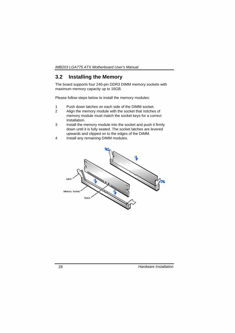
IMB203 LGA775 ATX Motherboard Userrsquos Manual
Hardware Description 32
MEMO
IMB203 LGA775 ATX Motherboard Userrsquos Manual
AMI BIOS Setup Utility 33
CHAPTER 5 AMI BIOS SETUP UTILITY
This chapter provides users with detailed description how to set up basic system configuration through the AMIBIOS8 BIOS setup utility 51 Starting To enter the setup screens follow the steps below 1 Turn on the computer and press the ltDelgt key immediately 2 After you press the ltDeletegt key the main BIOS setup menu
displays You can access the other setup screens from the main BIOS setup menu such as the Chipset and Power menus
52 Navigation Keys The BIOS setuputility uses a key-based navigation system called hot keys Most of the BIOS setup utility hot keys can be used at any time during the setup navigation process These keys include ltF1gt ltF10gt ltEntergt ltESCgt ltArrowgt keys and so on
Note Some of navigation keys differ from one screen to another
IMB203 LGA775 ATX Motherboard Userrsquos Manual
AMI BIOS Setup Utility 34
LeftRight The Left ltArrowgt keys allow you to select a setup screen
UpDown The Up and Down ltArrowgt keys allow you to select a setup screen or sub-screen
+minus PlusMinus The Plus and Minus ltArrowgt keys allow you to change the field value of a particular setup item
Tab The ltTabgt key allows you to select setup fields
F1 The ltF1gt key allows you to display the General Help screen
F10 The ltF10gt key allows you to save any changes you have made and exit Setup Press the ltF10gt key to save your changes
Esc
The ltEscgt key allows you to discard any changes you have made and exit the Setup Press the ltEscgt key to exit the setup without saving your changes
Enter
The ltEntergt key allows you to display or change the setup option listed for a particular setup item The ltEntergt key can also allow you to display the setup sub- screens
IMB203 LGA775 ATX Motherboard Userrsquos Manual
AMI BIOS Setup Utility 35
53 Main Menu When you first enter the Setup Utility you will enter the Main setup screen You can always return to the Main setup screen by selecting the Main tab There are two Main Setup options They are described in this section The Main BIOS Setup screen is shown below
System TimeDate
Use this option to change the system time and date Highlight System Time or System Date using the ltArrowgt keys Enter new values through the keyboard Press the ltTabgt key or the ltArrowgt keys to move between fields The date must be entered in MMDDYY format The time is entered in HHMMSS format
IMB203 LGA775 ATX Motherboard Userrsquos Manual
AMI BIOS Setup Utility 36
54 Advanced Menu The Advanced menu allows users to set configuration of the CPU and other system devices You can select any of the items in the left frame of the screen to go to the sub menus
CPU Configuration IDE Configuration SuperIO Configuration Hardware Health Configuration ACPI Configuration AHCI Configuration Intel iAMT Configuration Intel VT-d Configuration MPS Configuration PCI Express Configuration Trusted Computing USB Configuration
For items marked with ldquo rdquo please press ltEntergt for more options
IMB203 LGA775 ATX Motherboard Userrsquos Manual
AMI BIOS Setup Utility 37
CPU Configuration This screen shows the CPU Configuration and you can change the value of the selected option
Max CPUID Value Limit
You can enable this item to let legacy operating systems boot even without support for CPUs with extended CPU ID functions
Execute-Disable Bit Capability This item helps you enable or disable the No-Execution Page Protection Technology
Core Multi-Processing This feature controls the functionality of the Core Multi-Processing to allow the processor to execute multitasking function
PECI Use this item PECI (Platform Environment Control Interface) to execute the processor temperature monitoring and management
IMB203 LGA775 ATX Motherboard Userrsquos Manual
AMI BIOS Setup Utility 38
Intel (R) C-STATE tech Use this item to enable or disable the C-State technology
IDE Configuration You can use this screen to select options for the IDE Configuration and change the value of the selected option A description of the selected item appears on the right side of the screen For items marked with ldquo rdquo please press ltEntergt for more options
SATA1 Configuration
Use this item to control the onboard SATA controller Here are the options for your selection Compatible Disabled and Enhanced
Configure SATA1 as Use this item to choose the SATA operation mode Here are the options for your selection IDE and AHCI
SATA2 Configuration Use this item to control the onboard SATA controller Here are the options for your selection Enhanced and Disabled
IMB203 LGA775 ATX Motherboard Userrsquos Manual
AMI BIOS Setup Utility 39
PrimarySecondaryThird IDE Master Select one of the hard disk drives to configure IDE devices installed in the system by pressing ltEntergt for more options
Fifth IDE Master Select one of the hard disk drives to configure IDE devices installed in the system by pressing ltEntergt for more options
IMB203 LGA775 ATX Motherboard Userrsquos Manual
AMI BIOS Setup Utility 40
SuperIO Configuration You can use this screen to select options for the SuperIO Configuration and change the value of the selected option A description of the selected item appears on the right side of the screen
Serial Port1 Address
This option specifies the base IO port address and Interrupt Request address of serial port 1 The Optimal setting is 3F8IRQ4 The Fail-Safe default setting is Disabled
Serial Port2 Address This option specifies the base IO port address and Interrupt Request address of serial port 2 The Optimal setting is 2F8IRQ3 The Fail-Safe setting is Disabled
Parallel Port Address This item allows you to determine the IO address for onboard parallel port There are several options for your selection
Parallel Port Mode
IMB203 LGA775 ATX Motherboard Userrsquos Manual
AMI BIOS Setup Utility 41
Select an operating mode for the onboard parallel (printer) port
Parallel Port IRQ Use this item to set up the IRQ for onboard parallel port
Serial Port3 Address This item specifies the base IO port address and Interrupt Request address of serial port 3 The Optimal setting is 3E8IRQ11 The Fail-Safe default setting is Disabled
Serial Port3 IRQ This item specifies the IRQ used by the serial port 3
Serial Port4 Address This item specifies the base IO port address and Interrupt Request address of serial port 4 The Optimal setting is 2E8IRQ10 The Fail-Safe default setting is Disabled
Serial Port4 IRQ This item specifies the IRQ used by the serial port 4
IMB203 LGA775 ATX Motherboard Userrsquos Manual
AMI BIOS Setup Utility 42
Hardware Health Configuration This screen shows the Hardware Health Configuration and a description of the selected item appears on the right side of the screen
HW Health Configuration
This screen displays the temperature of CPU and System Fan Speed Vcore etc
IMB203 LGA775 ATX Motherboard Userrsquos Manual
AMI BIOS Setup Utility 43
ACPI Configuration You can use this screen to select options for the ACPI Configuration and change the value of the selected option A description of the selected item appears on the right side of the screen
General ACPI Configuration
Scroll to this item and press ltEntergt to view the General ACPI Configuration sub menu which contains General ACPI (Advanced Configuration and Power Management Interface) options for your configuration
Advanced ACPI Configuration Scroll to this item and press ltEntergt to view the Advanced ACPI Configuration sub menu which contains Advanced ACPI (Advanced Configuration and Power Management Interface) options for your configuration
Chipset ACPI Configuration Scroll to this item and press ltEntergt to view the Chipset ACPI Configuration sub menu which contains Chipset ACPI (Advanced Configuration and Power Management
IMB203 LGA775 ATX Motherboard Userrsquos Manual
AMI BIOS Setup Utility 44
Interface) options for your configuration AHCI Configuration
You can use this screen to select options for the AHCI Configuration and change the value of the selected option A description of the selected item appears on the right side of the screen
AHCI BIOS Support You can enable or disable this item to control the AHCI function of the SATA controller
IMB203 LGA775 ATX Motherboard Userrsquos Manual
AMI BIOS Setup Utility 45
Intel iAMT Configuration You can use this screen to select options for the Intel iAMT Configuration and change the value of the selected option A description of the selected item appears on the right side of the screen
Intel iAMT Support
You can enable this item to support iAMT (active management technology) function to follow up the procedure for the access to AMI program screen
Unconfigure iAMTME Use this item to unconfigure the iAMTME settings
IMB203 LGA775 ATX Motherboard Userrsquos Manual
AMI BIOS Setup Utility 46
Intel VT-d Configuration You can use this screen to select options for the Intel VT-d Configuration and change the value of the selected option A description of the selected item appears on the right side of the screen
Intel VT-d Virtualization Technology for Directed IO (VT-d) extends Virtualization Technology (VT) roadmap by providing hardware assists for virtualization solution VT-d can help end users improve security and reliability of the systems and also improve performance of IO devices in virtualized environment Here are the options for your selection Disabled and Enabled
IMB203 LGA775 ATX Motherboard Userrsquos Manual
AMI BIOS Setup Utility 47
Remote Access Configuration You can use this screen to select options for the Remote Access Configuration and change the value of the selected option A description of the selected item appears on the right side of the screen
Remote Access Use this item to enable or disable the Remote Access function
IMB203 LGA775 ATX Motherboard Userrsquos Manual
AMI BIOS Setup Utility 48
PCI Express Configuration This screen shows the PCI Express Configuration and you can change its value A description of the selected item appears on the right side of the screen
Active State Power-Management
Use this item to enable or disable the function of Active State Power-Management to provide you with lower power consumption The default setting is Disabled
IMB203 LGA775 ATX Motherboard Userrsquos Manual
AMI BIOS Setup Utility 49
Trusted Computing You can use this screen to select options for the Trusted Computing and change the value of the selected option A description of the selected item appears on the right side of the screen
TCGTPM SUPPORT Use this item to control the Trusted Platform Module (TPM) function
IMB203 LGA775 ATX Motherboard Userrsquos Manual
AMI BIOS Setup Utility 50
USB Configuration You can use this screen to select options for the USB Configuration and change the value of the selected option A description of the selected item appears on the right side of the screen
USB Functions
This item allows you to enable or disable USB functions
Legacy USB Support Use this item to enable or disable support for USB device on legacy operating system The default setting is Enabled
USB 20 Controller Mode Use this item to configure the USB 20 controller The default setting is HiSpeed
BIOS EHCI Hand-Off Enabling this item provide the support for operating systems without an EHCI hand-off feature The default setting is Enabled
IMB203 LGA775 ATX Motherboard Userrsquos Manual
AMI BIOS Setup Utility 51
IMB203 LGA775 ATX Motherboard Userrsquos Manual
AMI BIOS Setup Utility 52
55 PCI PnP Menu The PCI PnP menu allows users to change the advanced settings for PCIPnP devices
Clear NVRAM
Use this item to clear the data in the NVRAM (CMOS) Here are the options for your selection No and Yes
Plug amp Play OS When the setting is No Use this item to configure all the devices in the system When the setting is Yes and if you install a Plug and Play operating system the operating system configures the Plug and Play devices not required for boot The default setting is No
IMB203 LGA775 ATX Motherboard Userrsquos Manual
AMI BIOS Setup Utility 53
PCI Latency Timer This item controls how long a PCI device can hold the PCI bus before another takes over The longer the latency the longer the PCI device can retain control of the bus before handing it over to another PCI device There are several options for your selection
Allocate IRQ to PCI VGA This item allows BIOS to choose an IRQ to assign for the PCI VGA card Here are the options for your selection No and Yes
Palette Snooping Some old graphic controllers need to ldquosnooprdquo on the VGA palette and then map it to their display as a way to provide boot information and VGA compatibility This item allows such snooping to take place Here are the options for your selection Disabled and Enabled
PCI IDE BusMaster This item is a toggle for the built-in driver that allows the onboard IDE controller to perform DMA (Direct Memory Access) transfer Here are the options for your selection Disabled and Enabled
OffBoard PCIISA IDE Card This item is for any other non-onboard PCIISA IDE controller adapter There are several options for your selection
IRQ3457910111415 These items will allow you to assign each system interrupt a type depending on the type of device using the interrupt The option ldquoAvailablerdquo means the IRQ is going to assign automatically Here are the options for your selection Available and Reserved
DMA Channel 013567 These items will allow you to assign each DMA channel a type depending on the type of device using the channel The option ldquoAvailablerdquo means the channel is going to assign automatically Here are the options for your selection Available and Reserved
IMB203 LGA775 ATX Motherboard Userrsquos Manual
AMI BIOS Setup Utility 54
56 Boot Menu The Boot menu allows users to change boot options of the system You can select any of the items in the left frame of the screen to go to the sub menus
Boot Settings Configuration Boot Device Priority Removable Drives
For items marked with ldquo rdquo please press ltEntergt for more options
IMB203 LGA775 ATX Motherboard Userrsquos Manual
AMI BIOS Setup Utility 55
Boot Settings Configuration
Quick Boot
Enabling this item lets the BIOS skip some power on self tests (POST) The default setting is Enabled
AddOn ROM Display Mode This item selects the display mode for option ROM The default setting is Force BIOS
Boot Num-Lock Use this item to select the power-on state for the NumLock The default setting is On
PS2 Mouse Support This item determines if the BIOS should reserve IRQ12 for the PS2 mouse or allow other devices to make use of this IRQ Here are the options for your selection Auto Enabled and Disabled
Wait For lsquoF1rsquo Of Error If this item is enabled the system waits for the F1 key to be pressed when error occurs The default setting is Enabled
Hit lsquoDELrsquo Message Display If this item is enabled the system displays the message
IMB203 LGA775 ATX Motherboard Userrsquos Manual
AMI BIOS Setup Utility 56
ldquoPress DEL to run Setuprdquo during POST The default setting is Enabled
Interrupt 19 Capture If this item is enabled this function makes the option ROMs to trap Interrupt 19 The default setting is Disabled
Boot Device Priority The Boot Device Priority screen specifies the boot device priority sequence from the available devices
IMB203 LGA775 ATX Motherboard Userrsquos Manual
AMI BIOS Setup Utility 57
Removable Drives Use this screen to view the removable drives in the system The BIOS will attempt to arrange the removable drive boot sequence automatically You can also change the booting sequence
IMB203 LGA775 ATX Motherboard Userrsquos Manual
AMI BIOS Setup Utility 58
57 Security Menu The Security menu allows users to change the security settings for the system
Supervisor Password
This item indicates whether a supervisor password has been set If the password has been installed Installed displays If not Not Installed displays
User Password This item indicates whether a user password has been set If the password has been installed Installed displays If not Not Installed displays
Change Supervisor Password Select this option and press ltEntergt to access the sub menu You can use the sub menu to change the supervisor password
Change User Password Select this option and press ltEntergt to access the sub menu You can use the sub menu to change the user password
IMB203 LGA775 ATX Motherboard Userrsquos Manual
AMI BIOS Setup Utility 59
58 Chipset Menu The Chipset menu allows users to change the advanced chipset settings You can select any of the items in the left frame of the screen to go to the sub menus
North Bridge Configuration South Bridge Configuration ME Subsystem Configuration
For items marked with ldquo rdquo please press ltEntergt for more options
IMB203 LGA775 ATX Motherboard Userrsquos Manual
AMI BIOS Setup Utility 60
North Bridge Configuration
Memory Remap Feature
Use this item to enable or disable the remapping of the overlapped PCI memory above the total physical memory Only 64-bit OS supports this function
DRAM Frequency This item allows you to control the Memory Clock
Configure DRAM Timing by SPD This item can enable or disable DRAM timing by SPD (Serial Presence Detect) device which is a small EEPROM chip on the memory module containing important information about the module speed size addressing mode and various parameters
Memory Hole You can reserve this area of system memory for ISA adapter ROM When this area is reserved it cannot be cached Check the user information of peripherals that need to use this area o f system memory for the memory requirements Here are the options Disabled and 15M-16M
IMB203 LGA775 ATX Motherboard Userrsquos Manual
AMI BIOS Setup Utility 61
Initiate Graphic Adapter When using multiple graphics cards this item can select which graphics controller to be the primary display device during boot
IGD Graphics Mode Select This item allows you to select the amount of system memory used by the internal graphics device
PEG Port ConfigurationPEG Port This item is a toggle to enable or disable the PCI Express port Here are the options for your selection Auto and Disabled
Video Function Configuration Press ltEntergt for the sub-menu for setting up video function
IMB203 LGA775 ATX Motherboard Userrsquos Manual
AMI BIOS Setup Utility 62
South Bridge Configuration
GbE Wake Up From S5 This item specifies whether the system will be awakened from the S5 power
HDA Controller This item allows you to enable or disable the HD audio support
Restore on AC Power Loss This item can control how the PC will behave once power is restored following a power outage or other unexpected shutdown
PCIE Port Configuration This item allows you to set or disable the PCI Express Ports
IMB203 LGA775 ATX Motherboard Userrsquos Manual
AMI BIOS Setup Utility 63
ME Subsystem Configuration
It is strongly recommended that you do not modify these options unless you are an advanced user
IMB203 LGA775 ATX Motherboard Userrsquos Manual
AMI BIOS Setup Utility 64
59 Exit Menu The Exit menu allows users to load your system configuration with optimal or failsafe default values
Save Changes and Exit
When you have completed the system configuration changes select this option to leave Setup and reboot the computer so the new system configuration parameters can take effect Select Save Changes and Exit from the Exit menu and press ltEntergt Select Ok to save changes and exit
Discard Changes and Exit Select this option to quit Setup without making any permanent changes to the system configuration Select Discard Changes and Exit from the Exit menu and press ltEntergt Select Ok to discard changes and exit
Load Optimal Defaults It automatically sets all Setup options to a complete set of default settings when you select this option The Optimal settings are designed for maximum system performance but may not work best for all computer applications In particular do not use the Optimal Setup options if your
IMB203 LGA775 ATX Motherboard Userrsquos Manual
AMI BIOS Setup Utility 65
computer is experiencing system configuration problems Select Load Optimal Defaults from the Exit menu and press ltEntergt
Load Fail-Safe Defaults It automatically sets all Setup options to a complete set of default settings when you select this option The Fail-Safe settings are designed for maximum system stability but not maximum performance Select the Fail-Safe Setup options if your computer is experiencing system configuration problems Select Load Fail-Safe Defaults from the Exit menu and press ltEntergt Select Ok to load Fail-Safe defaults
IMB203 LGA775 ATX Motherboard Userrsquos Manual
AMI BIOS Setup Utility 66
MEMO
IMB203 LGA775 ATX Motherboard Userrsquos Manual
Installation of Drivers 67
CHPATER 6 INSTALLATION OF DRIVERS
The device drivers are located on the Product Information CD-ROM that comes with the IMB203 Series package The auto-run function of drivers will guide you to install the utilities and device drivers under a Windows system You can follow the onscreen instructions to install these devices
Chipse VGA LAN Audio iAMT MEI
61 Installing Chipset Driver 1 Run the SETUPEXE program from the driver directory in
your driver CD Click ldquoNextrdquo to next step
IMB203 LGA775 ATX Motherboard Userrsquos Manual
Installation of Drivers 68
2 An Intelreg License Agreement appears to show you the important information Click ldquoYesrdquo to next step
3 Refer to the Readme file below to view the system requirements and installation information
IMB203 LGA775 ATX Motherboard Userrsquos Manual
Installation of Drivers 69
3-1 Please wait while running the following setup operations
3-2 Please wait while running the following setup operations
IMB203 LGA775 ATX Motherboard Userrsquos Manual
Installation of Drivers 70
4 Click ldquoFinishrdquo to complete the setup process
5 You will be asked to reboot your computer when the installation is completed Please click ldquoYes I want to restart my computer nowrdquo if you donrsquot need to install any other drivers Otherwise please click ldquoNo I will restart my computer laterrdquo and go on next step
IMB203 LGA775 ATX Motherboard Userrsquos Manual
Installation of Drivers 71
62 Installing VGA Driver 1 Run the SETUPEXE program from the driver directory in
your driver CD Click ldquoNextrdquo to next step
2 An Intelreg License Agreement appears to show you the
important information Click ldquoYesrdquo to next step
IMB203 LGA775 ATX Motherboard Userrsquos Manual
Installation of Drivers 72
3 The message of Readme File Information appears to show you the system requirements and installation information Please click ldquoNextrdquo
4 Please wait while running the following setup operations
When this message appears please click ldquoNextrdquo
IMB203 LGA775 ATX Motherboard Userrsquos Manual
Installation of Drivers 73
5 Click ldquoFinishrdquo to complete the setup process
6 You will be asked to reboot your computer when the installation is completed Please click ldquoYes I want to restart my computer nowrdquo if you donrsquot need to install any other drivers Otherwise please click ldquoNo I will restart my computer laterrdquo and click ldquoFinishrdquo to complete the installation
IMB203 LGA775 ATX Motherboard Userrsquos Manual
Installation of Drivers 74
63 Installing LAN Driver
11 Run the InstallShield Wizard for Network Connections from
the driver directory in your driver CD Click ldquoNextrdquo to next step
IMB203 LGA775 ATX Motherboard Userrsquos Manual
Installation of Drivers 75
12 An Intelreg License Agreement appears to show you the important information Click ldquoYesrdquo to next step
13 A Setup Options window appears that you can select the
program features you want to install
IMB203 LGA775 ATX Motherboard Userrsquos Manual
Installation of Drivers 76
2 Click ldquoInstallrdquo to start the installation
3 Please wait while running the following installation operation
IMB203 LGA775 ATX Motherboard Userrsquos Manual
Installation of Drivers 77
4 Click ldquoFinishrdquo to complete the installation
Note The Driver item [Wake on Directed Packet] default is Enabled under Windows Vista
格式化 字型 (符號) Arial
格式化 字型 (符號) Arial
格式化 字型 斜體 字型色彩 黑色 (符號) Arial 非加寬 緊縮
格式化 字型 斜體 字型色彩 黑色 (符號) Arial 非加寬 緊縮
格式化 字型 (符號) Arial 非加寬 緊縮
IMB203 LGA775 ATX Motherboard Userrsquos Manual
Installation of Drivers 78
64 Installing AUDIO Driver 1 Run the InstallShield Wizard for Realtek High Definition
Audio Driver from the driver directory in your driver CD Click ldquoNextrdquo to next step
IMB203 LGA775 ATX Motherboard Userrsquos Manual
Installation of Drivers 79
2 Click ldquoInstallrdquo to start the installation and wait while running the installation operation
3 Click ldquoFinishrdquo to complete the installation
IMB203 LGA775 ATX Motherboard Userrsquos Manual
Installation of Drivers 80
65 Installing iAMT (Active Management Technology) Driver
Note You must download and properly install the required NET version 35 provided from a separate downloading of the actual FimwareTools kit releases posted on VIP prior to loading the MEILMS Driver stack
651 LMS_SOL Setup
1 Run the setup program to install Intelreg Active Management Technology onto your computer It is strongly recommended that you exit all programs before continuing Click ldquoNextrdquo to next step
格式化 字型 (符號) Arial
格式化 字型 (符號) Arial 非加寬 緊縮
IMB203 LGA775 ATX Motherboard Userrsquos Manual
Installation of Drivers 81
2 An Intelreg license agreement appears that you need to continue the setup program by clicking ldquoYesrdquo to accept the terms
IMB203 LGA775 ATX Motherboard Userrsquos Manual
Installation of Drivers 82
3 Refer to the Readme file below to view the system requirements and installation information Click ldquoNextrdquo to next setup
4 Please wait while running the following installation operation
IMB203 LGA775 ATX Motherboard Userrsquos Manual
Installation of Drivers 83
5 Click ldquoFinishrdquo to complete the installation
IMB203 LGA775 ATX Motherboard Userrsquos Manual
Installation of Drivers 84
652 LMS_SOL_IS Setup
1 Run the setup program to install Intelreg Active Management Technology onto your computer It is strongly recommended that you exit all programs before continuing Click ldquoNextrdquo to next step
IMB203 LGA775 ATX Motherboard Userrsquos Manual
Installation of Drivers 85
2 An Intelreg license agreement appears that you need to continue the setup program by clicking ldquoYesrdquo to accept the terms
IMB203 LGA775 ATX Motherboard Userrsquos Manual
Installation of Drivers 86
3 Refer to the Readme file below to view the system requirements and installation information Click ldquoNextrdquo to next setup
4 Please wait while running the following installation operation
IMB203 LGA775 ATX Motherboard Userrsquos Manual
Installation of Drivers 87
5 Click ldquoFinishrdquo to complete the installation
IMB203 LGA775 ATX Motherboard Userrsquos Manual
Installation of Drivers 88
66 Installing MEI (Management Engine Interface) Driver
Note You must download and properly install the required NET version 35 provided from a separate downloading of the actual FimwareTools kit releases posted on VIP prior to loading the MEILMS Driver stack
1 Run the setup program to install Intelreg Management Engine
Interface onto your computer It is strongly recommended that you exit all programs before continuing Click ldquoNextrdquo to next step
格式化 字型 (符號) Arial
格式化 字型 (符號) Arial 非加寬 緊縮
IMB203 LGA775 ATX Motherboard Userrsquos Manual
Installation of Drivers 89
2 An Intelreg license agreement appears that you need to continue the setup program by clicking ldquoYesrdquo to accept the terms
IMB203 LGA775 ATX Motherboard Userrsquos Manual
Installation of Drivers 90
3 Refer to the Readme file below to view the system requirements and installation information Click ldquoNextrdquo to next setup
4 Please wait while running the following installation operation
IMB203 LGA775 ATX Motherboard Userrsquos Manual
Installation of Drivers 91
5 Click ldquoFinishrdquo to complete the installation
IMB203 LGA775 ATX Motherboard Userrsquos Manual
Installation of Drivers 92
MEMO
IMB203 LGA775 ATX Motherboard Userrsquos Manual
Watchdog Timer 93
APPENDIX A WATCHDOG TIMER
Watchdog Timer Setting After the system stops working for a while it can be auto-reset by the Watchdog Timer The integrated Watchdog Timer can be set up in the system reset mode by program
Using the Watchdog Function Start darr Un-Lock WDT O 2E 87 Un-lock super IO
O 2E 87 Un-lock super IO darr Set WDT Function O 2E 2D O 2F 20 Select Logic device O 2E 07 O 2F 08 darr Activate WDT O 2E 30
O 2F 01 Set Second or Minute O 2E F5
O 2F N N=00 or 08(See below table) darr Set base timer O 2E F6
O 2F M=000102hellipFF(Hex) Value=0 to 255 darr WDT counting
re-set timer O 2E F6
O 2F M M=000102hellipFF(See below table) darr
格式化
格式化 項目符號及編號
格式化 項目符號及編號
格式化 字型 8 點 字型色彩黑色
格式化 字型 8 點 字型色彩黑色
格式化 定位點 1257 字元左 + 不在 1012 字元 + 1386字元
格式化 字型 8 點 字型色彩黑色
格式化 定位點 1257 字元左 + 不在 134 字元 + 1362字元
格式化 字型色彩 黑色
格式化 字型色彩 黑色
刪除
IMB203 LGA775 ATX Motherboard Userrsquos Manual
Watchdog Timer 94
IF No re-set timer WDT time-out generate RESET IF to disable WDT O 2E 30
O 2F 00 Can be disable at any time
N=00
M= 00h Time-out Disable 01h Time-out occurs after 1 second 02h Time-out occurs after 2 second 03h Time-out occurs after 3 second helliphelliphelliphelliphelliphelliphelliphelliphellip FFh Time-out occurs after 255 second
N=08
M= 00h Time-out Disable 01h Time-out occurs after 1 minute 02h Time-out occurs after 2 minutes 03h Time-out occurs after 3 minutes helliphelliphelliphelliphelliphelliphelliphelliphellip
FFh Time-out occurs after 255 minutes
格式化 字型色彩 黑色
格式化 字型色彩 黑色
IMB203 LGA775 ATX Motherboard Userrsquos Manual
PCI IRQ Routing 95
APPENDIX B PCI IRQ ROUTING
PICMG PCI IRQ Routing
Device ID Slot Int
PCI Slot 0 31 0 BCDA PCI Slot 1 30 1 CDAB PCI Slot 2 29 2 DABC PCI Slot 3 28 3 ABCD
IMB203 LGA775 ATX Motherboard Userrsquos Manual
PCI IRQ Routing 96
MEMO
IMB203 LGA775 ATX Motherboard Userrsquos Manual
Configuring SATA for RAID Function 97
APPENDIX C CONFIGURING SATA FOR RAID
FUNCTION
Configuring SATA Hard Drive(s) for RAID Function (Controller IntelregICH10DODO DH only) Please follow up the steps below to configure SATA hard drive(s) (1) Install SATA hard drive(s) in your system (2) Enter the BIOS Setup to configure SATA controller mode and boot
sequence (3) Configure RAID by the RAID BIOS (4) Install the SATA controller driver during the OS installation Before you begin the SATA configuration please prepare (a) Two SATA hard drives (to ensure optimal performance it is
recommended that you use two hard drives with identical model and capacity) If you do not want to create RAID with the SATA controller you may prepare only one hard drive
(b) An empty formatted floppy disk (c) Windows XP setup disk (1) Installing SATA hard drive(s) in your system
Connect one end of the SATA signal cable to the rear of the SATA hard drive and the other end to available SATA port(s) on the board Then connect the power connector of power supply to the hard drive
(2) Configuring SATA controller mode and boot sequence by the BIOS Setup You have to make sure whether the SATA controller is configured correctly by system BIOS Setup and set up BIOS boot sequence for the SATA hard drive(s)
IMB203 LGA775 ATX Motherboard Userrsquos Manual
Configuring SATA for RAID Function 98
(2)-1-1 Turn on your system and then press the Del button to enter BIOS Setup during running POST (Power-On Self Test) If you want to create RAID just go to the Advanced Settings menuIDE configuration select the Configure SATA1 as and press ltEntergt for more options
IMB203 LGA775 ATX Motherboard Userrsquos Manual
Configuring SATA for RAID Function 99
(2)-1-2 A list of options appears please select RAID
IMB203 LGA775 ATX Motherboard Userrsquos Manual
Configuring SATA for RAID Function 100
(2)-2 Set CDROM for First Boot Device under the Boot Settings menu to boot CD-ROM after system restarts
(2)-3 Save and exit the BIOS Setup
IMB203 LGA775 ATX Motherboard Userrsquos Manual
Configuring SATA for RAID Function 101
(3) Configuring RAID by the RAID BIOS Enter the RAID BIOS setup utility to configure a RAID array Skip this step and proceed to Section 4 if you do not want to create a RAID (3)-1 After the POST memory testing and before the operating
system booting a message Press ltCtrl-Igt to enter Configuration Utility shows up accordingly press ltCTRL+ Igt to enter the RAID BIOS setup utility
(3)-2 After you press ltCTRL+ Igt the Create RAID Volume screen will appear If you want to create a RAID array select the Create RAID Volume option in the Main Menu and press ENTER
IMB203 LGA775 ATX Motherboard Userrsquos Manual
Configuring SATA for RAID Function 102
(3)-3-1 After entering the CREATE VOLUME MENU screen you can type the disk array name with 1~16 letters (letters cannot be special characters) in the item ldquoNamerdquo
(3)-3-2 When finished press ENTER to select a RAID level There are three RAID levels RAID0 RAID1 and RAID5 amp RAID10 Select a RAID level and press ENTER
IMB203 LGA775 ATX Motherboard Userrsquos Manual
Configuring SATA for RAID Function 103
(3)-4 Set the stripe block size The KB is the standard unit of stripe block size The stripe block size can be 4KB to 128KB After the setting press ENTER for the array capacity
(3)-5 After setting all the items on the menu select Create Volume
and press ENTER to start creating the RAID array
IMB203 LGA775 ATX Motherboard Userrsquos Manual
Configuring SATA for RAID Function 104
(3)-6 When prompting the confirmation press ldquoYldquo to create this volume or ldquoNldquo to cancel the creation
After the creation is completed you can see detailed information about the RAID Array in the DISKVOLUME INFORMATION section including RAID mode disk block size disk name and disk capacity etc
IMB203 LGA775 ATX Motherboard Userrsquos Manual
Configuring SATA for RAID Function 105
Delete RAID Volume If you want to delete a RAID volume select the Delete RAID Volume option in Main Menu Press ENTER and follow on-screen instructions
Please press [ESC] to exit the RAID BIOS utility Now you can proceed to install a SATA driver controller and the operating system
IMB203 LGA775 ATX Motherboard Userrsquos Manual
Configuring SATA for RAID Function 106
(4) Making a SATA Driver Disk To install the operating system onto a serial ATA hard disk successfully you need to install the SATA controller driver during the OS installation Without the driver the hard disk may not be recognized during the Windows setup process First of all please format a blank floppy disk Secondly follow up these steps below to produce a SATA driver disk Users can insert the Driver CD and the formatted blank floppy disk in another system And then please copy all of file of the f6flpy32 folder in the Driver CD to a floppy disk Note Please copy all of file of the f6flpy64 folder if installing 64-bit
Windows Operating System
IMB203 LGA775 ATX Motherboard Userrsquos Manual
Configuring SATA for RAID Function 107
(5) Installing the SATA controller driver during the OS installation Now the SATA driver disk is ready and BIOS settings configured you can proceed to install Windows 2000XP onto your SATA hard drive using the SATA driver Here is an example for Windows XP installation (5)-1 Restart your system to boot the Windows 2000XP Setup disk
and press F6 button as soon as you see the message Press F6 if you need to install a 3rd party SCSI or RAID driver After pressing the F6 button there will be a few moments for some files being loaded before next screen appears
IMB203 LGA775 ATX Motherboard Userrsquos Manual
Configuring SATA for RAID Function 108
(5)-2 When you see the screen below insert the floppy disk containing the SATA driver and press ldquoSrdquo
(5)-3 If the Setup correctly recognizes the driver of the floppy disk
a controller menu will appear below Use the ARROW keys to select Intel(R) ICH8RICH9RICH10RDO SATA RAID Controller and press ENTER Then it will begin to load the SATA driver from the floppy disk
IMB203 LGA775 ATX Motherboard Userrsquos Manual
Configuring SATA for RAID Function 109
Note If a message on the screen saying that one or some file(s) cannot be found please check the floppy disk or copy the correct SATA driver again from the driver CD
IMB203 LGA775 ATX Motherboard Userrsquos Manual
Configuring SATA for RAID Function 110
MEMO
IMB203 LGA775 ATX Motherboard Userrsquos Manual
iAMT Settings 111
APPENDIX D iAMT SETTINGS
The Intelreg Active Management Technology (Intelreg iAMT) has decreased a major barrier to IT efficiency that uses built-in platform capabilities and popular third-party management and security applications to allow IT a better discovering healing and protection their networked computing assets In order to utilize Intel iAMT you must enter the ME BIOS (CTRL + P during system startup) change the ME BIOS password and then select ldquoIntelreg iAMTrdquo as the manageability feature
D1 Entering MEBx 1 You must go to BIOS TO start iAMT function 2 Exit from BIOS after starting iAMT and press Ctrl+P to enter MEBx Setting
It is better to press Ctrl+P before the screen popping out
格式化
IMB203 LGA775 ATX Motherboard Userrsquos Manual
iAMT Settings 112
D2 Set amp Change Password 1 You will be asked to set a password when first log in The default
password is lsquoadminrsquo
2 You will be asked to change the password before setting ME
Change Password
IMB203 LGA775 ATX Motherboard Userrsquos Manual
iAMT Settings 113
3 You must confirm your new password while revising (as Remark 1)
Remark 1 The new password must contain (example 11qqQQ) (default value)
Eight characters
One upper case
One lower case
One number
One special symbol such as $ or
( excepted)
Underline ( _ ) and space are valid characters for password but they wonrsquot make higher complexity
IMB203 LGA775 ATX Motherboard Userrsquos Manual
iAMT Settings 114
D3 Intelreg iAMT Settings 1 Select Intelreg iAMT Configuration and press ltENTERgt
2 Key in the Host Name If Intelreg iAMT set to lsquoDHCPlsquo the Host name must be identical to the operating system mechanic
IMB203 LGA775 ATX Motherboard Userrsquos Manual
iAMT Settings 115
3 Select TCPIP to get into Network interface and set it to lsquoENABLEDrsquo into DHCP Mode and set it to lsquoDISABLEDrsquo (as Remark 2) into Domain name and set the Intel Management Engine domain name such as lsquoAMTintelcomrsquo
(3-1)
(3-2)
IMB203 LGA775 ATX Motherboard Userrsquos Manual
iAMT Settings 116
Remark 2 DHCP Mode lsquoDISABLEDlsquo if DHCP Mode is disabled you can make the following settings
IP address
Subnet mask
IMB203 LGA775 ATX Motherboard Userrsquos Manual
iAMT Settings 117
Default Gateway address
Preferred DNS address
IMB203 LGA775 ATX Motherboard Userrsquos Manual
iAMT Settings 118
Alternate DNS address
Domain name
4 Exit from MEBx after completing the iAMT settings
IMB203 LGA775 ATX Motherboard Userrsquos Manual
iAMT Settings 119
D4 iAMT Web Console 1 From a web browser please type http(IP ADDRESS)16992
which connects to iAMT Web Example http1014021416992
2 To log on you will be required to type in username and password
for access to the Web
USER admin (default value)
PASS (MEBx password)
IMB203 LGA775 ATX Motherboard Userrsquos Manual
iAMT Settings 120
3 Enter the iAMT Web
4 Click Remote Control and select commands on the right side
IMB203 LGA775 ATX Motherboard Userrsquos Manual
iAMT Settings 121
5 When you have finished using the iAMT Web console close the Web browser
IMB203 LGA775 ATX Motherboard Userrsquos Manual
iAMT Settings 122
MEMO
IMB203 LGA775 ATX Motherboard Userrsquos Manual
AMI BIOS Setup Utility 33
CHAPTER 5 AMI BIOS SETUP UTILITY
This chapter provides users with detailed description how to set up basic system configuration through the AMIBIOS8 BIOS setup utility 51 Starting To enter the setup screens follow the steps below 1 Turn on the computer and press the ltDelgt key immediately 2 After you press the ltDeletegt key the main BIOS setup menu
displays You can access the other setup screens from the main BIOS setup menu such as the Chipset and Power menus
52 Navigation Keys The BIOS setuputility uses a key-based navigation system called hot keys Most of the BIOS setup utility hot keys can be used at any time during the setup navigation process These keys include ltF1gt ltF10gt ltEntergt ltESCgt ltArrowgt keys and so on
Note Some of navigation keys differ from one screen to another
IMB203 LGA775 ATX Motherboard Userrsquos Manual
AMI BIOS Setup Utility 34
LeftRight The Left ltArrowgt keys allow you to select a setup screen
UpDown The Up and Down ltArrowgt keys allow you to select a setup screen or sub-screen
+minus PlusMinus The Plus and Minus ltArrowgt keys allow you to change the field value of a particular setup item
Tab The ltTabgt key allows you to select setup fields
F1 The ltF1gt key allows you to display the General Help screen
F10 The ltF10gt key allows you to save any changes you have made and exit Setup Press the ltF10gt key to save your changes
Esc
The ltEscgt key allows you to discard any changes you have made and exit the Setup Press the ltEscgt key to exit the setup without saving your changes
Enter
The ltEntergt key allows you to display or change the setup option listed for a particular setup item The ltEntergt key can also allow you to display the setup sub- screens
IMB203 LGA775 ATX Motherboard Userrsquos Manual
AMI BIOS Setup Utility 35
53 Main Menu When you first enter the Setup Utility you will enter the Main setup screen You can always return to the Main setup screen by selecting the Main tab There are two Main Setup options They are described in this section The Main BIOS Setup screen is shown below
System TimeDate
Use this option to change the system time and date Highlight System Time or System Date using the ltArrowgt keys Enter new values through the keyboard Press the ltTabgt key or the ltArrowgt keys to move between fields The date must be entered in MMDDYY format The time is entered in HHMMSS format
IMB203 LGA775 ATX Motherboard Userrsquos Manual
AMI BIOS Setup Utility 36
54 Advanced Menu The Advanced menu allows users to set configuration of the CPU and other system devices You can select any of the items in the left frame of the screen to go to the sub menus
CPU Configuration IDE Configuration SuperIO Configuration Hardware Health Configuration ACPI Configuration AHCI Configuration Intel iAMT Configuration Intel VT-d Configuration MPS Configuration PCI Express Configuration Trusted Computing USB Configuration
For items marked with ldquo rdquo please press ltEntergt for more options
IMB203 LGA775 ATX Motherboard Userrsquos Manual
AMI BIOS Setup Utility 37
CPU Configuration This screen shows the CPU Configuration and you can change the value of the selected option
Max CPUID Value Limit
You can enable this item to let legacy operating systems boot even without support for CPUs with extended CPU ID functions
Execute-Disable Bit Capability This item helps you enable or disable the No-Execution Page Protection Technology
Core Multi-Processing This feature controls the functionality of the Core Multi-Processing to allow the processor to execute multitasking function
PECI Use this item PECI (Platform Environment Control Interface) to execute the processor temperature monitoring and management
IMB203 LGA775 ATX Motherboard Userrsquos Manual
AMI BIOS Setup Utility 38
Intel (R) C-STATE tech Use this item to enable or disable the C-State technology
IDE Configuration You can use this screen to select options for the IDE Configuration and change the value of the selected option A description of the selected item appears on the right side of the screen For items marked with ldquo rdquo please press ltEntergt for more options
SATA1 Configuration
Use this item to control the onboard SATA controller Here are the options for your selection Compatible Disabled and Enhanced
Configure SATA1 as Use this item to choose the SATA operation mode Here are the options for your selection IDE and AHCI
SATA2 Configuration Use this item to control the onboard SATA controller Here are the options for your selection Enhanced and Disabled
IMB203 LGA775 ATX Motherboard Userrsquos Manual
AMI BIOS Setup Utility 39
PrimarySecondaryThird IDE Master Select one of the hard disk drives to configure IDE devices installed in the system by pressing ltEntergt for more options
Fifth IDE Master Select one of the hard disk drives to configure IDE devices installed in the system by pressing ltEntergt for more options
IMB203 LGA775 ATX Motherboard Userrsquos Manual
AMI BIOS Setup Utility 40
SuperIO Configuration You can use this screen to select options for the SuperIO Configuration and change the value of the selected option A description of the selected item appears on the right side of the screen
Serial Port1 Address
This option specifies the base IO port address and Interrupt Request address of serial port 1 The Optimal setting is 3F8IRQ4 The Fail-Safe default setting is Disabled
Serial Port2 Address This option specifies the base IO port address and Interrupt Request address of serial port 2 The Optimal setting is 2F8IRQ3 The Fail-Safe setting is Disabled
Parallel Port Address This item allows you to determine the IO address for onboard parallel port There are several options for your selection
Parallel Port Mode
IMB203 LGA775 ATX Motherboard Userrsquos Manual
AMI BIOS Setup Utility 41
Select an operating mode for the onboard parallel (printer) port
Parallel Port IRQ Use this item to set up the IRQ for onboard parallel port
Serial Port3 Address This item specifies the base IO port address and Interrupt Request address of serial port 3 The Optimal setting is 3E8IRQ11 The Fail-Safe default setting is Disabled
Serial Port3 IRQ This item specifies the IRQ used by the serial port 3
Serial Port4 Address This item specifies the base IO port address and Interrupt Request address of serial port 4 The Optimal setting is 2E8IRQ10 The Fail-Safe default setting is Disabled
Serial Port4 IRQ This item specifies the IRQ used by the serial port 4
IMB203 LGA775 ATX Motherboard Userrsquos Manual
AMI BIOS Setup Utility 42
Hardware Health Configuration This screen shows the Hardware Health Configuration and a description of the selected item appears on the right side of the screen
HW Health Configuration
This screen displays the temperature of CPU and System Fan Speed Vcore etc
IMB203 LGA775 ATX Motherboard Userrsquos Manual
AMI BIOS Setup Utility 43
ACPI Configuration You can use this screen to select options for the ACPI Configuration and change the value of the selected option A description of the selected item appears on the right side of the screen
General ACPI Configuration
Scroll to this item and press ltEntergt to view the General ACPI Configuration sub menu which contains General ACPI (Advanced Configuration and Power Management Interface) options for your configuration
Advanced ACPI Configuration Scroll to this item and press ltEntergt to view the Advanced ACPI Configuration sub menu which contains Advanced ACPI (Advanced Configuration and Power Management Interface) options for your configuration
Chipset ACPI Configuration Scroll to this item and press ltEntergt to view the Chipset ACPI Configuration sub menu which contains Chipset ACPI (Advanced Configuration and Power Management
IMB203 LGA775 ATX Motherboard Userrsquos Manual
AMI BIOS Setup Utility 44
Interface) options for your configuration AHCI Configuration
You can use this screen to select options for the AHCI Configuration and change the value of the selected option A description of the selected item appears on the right side of the screen
AHCI BIOS Support You can enable or disable this item to control the AHCI function of the SATA controller
IMB203 LGA775 ATX Motherboard Userrsquos Manual
AMI BIOS Setup Utility 45
Intel iAMT Configuration You can use this screen to select options for the Intel iAMT Configuration and change the value of the selected option A description of the selected item appears on the right side of the screen
Intel iAMT Support
You can enable this item to support iAMT (active management technology) function to follow up the procedure for the access to AMI program screen
Unconfigure iAMTME Use this item to unconfigure the iAMTME settings
IMB203 LGA775 ATX Motherboard Userrsquos Manual
AMI BIOS Setup Utility 46
Intel VT-d Configuration You can use this screen to select options for the Intel VT-d Configuration and change the value of the selected option A description of the selected item appears on the right side of the screen
Intel VT-d Virtualization Technology for Directed IO (VT-d) extends Virtualization Technology (VT) roadmap by providing hardware assists for virtualization solution VT-d can help end users improve security and reliability of the systems and also improve performance of IO devices in virtualized environment Here are the options for your selection Disabled and Enabled
IMB203 LGA775 ATX Motherboard Userrsquos Manual
AMI BIOS Setup Utility 47
Remote Access Configuration You can use this screen to select options for the Remote Access Configuration and change the value of the selected option A description of the selected item appears on the right side of the screen
Remote Access Use this item to enable or disable the Remote Access function
IMB203 LGA775 ATX Motherboard Userrsquos Manual
AMI BIOS Setup Utility 48
PCI Express Configuration This screen shows the PCI Express Configuration and you can change its value A description of the selected item appears on the right side of the screen
Active State Power-Management
Use this item to enable or disable the function of Active State Power-Management to provide you with lower power consumption The default setting is Disabled
IMB203 LGA775 ATX Motherboard Userrsquos Manual
AMI BIOS Setup Utility 49
Trusted Computing You can use this screen to select options for the Trusted Computing and change the value of the selected option A description of the selected item appears on the right side of the screen
TCGTPM SUPPORT Use this item to control the Trusted Platform Module (TPM) function
IMB203 LGA775 ATX Motherboard Userrsquos Manual
AMI BIOS Setup Utility 50
USB Configuration You can use this screen to select options for the USB Configuration and change the value of the selected option A description of the selected item appears on the right side of the screen
USB Functions
This item allows you to enable or disable USB functions
Legacy USB Support Use this item to enable or disable support for USB device on legacy operating system The default setting is Enabled
USB 20 Controller Mode Use this item to configure the USB 20 controller The default setting is HiSpeed
BIOS EHCI Hand-Off Enabling this item provide the support for operating systems without an EHCI hand-off feature The default setting is Enabled
IMB203 LGA775 ATX Motherboard Userrsquos Manual
AMI BIOS Setup Utility 51
IMB203 LGA775 ATX Motherboard Userrsquos Manual
AMI BIOS Setup Utility 52
55 PCI PnP Menu The PCI PnP menu allows users to change the advanced settings for PCIPnP devices
Clear NVRAM
Use this item to clear the data in the NVRAM (CMOS) Here are the options for your selection No and Yes
Plug amp Play OS When the setting is No Use this item to configure all the devices in the system When the setting is Yes and if you install a Plug and Play operating system the operating system configures the Plug and Play devices not required for boot The default setting is No
IMB203 LGA775 ATX Motherboard Userrsquos Manual
AMI BIOS Setup Utility 53
PCI Latency Timer This item controls how long a PCI device can hold the PCI bus before another takes over The longer the latency the longer the PCI device can retain control of the bus before handing it over to another PCI device There are several options for your selection
Allocate IRQ to PCI VGA This item allows BIOS to choose an IRQ to assign for the PCI VGA card Here are the options for your selection No and Yes
Palette Snooping Some old graphic controllers need to ldquosnooprdquo on the VGA palette and then map it to their display as a way to provide boot information and VGA compatibility This item allows such snooping to take place Here are the options for your selection Disabled and Enabled
PCI IDE BusMaster This item is a toggle for the built-in driver that allows the onboard IDE controller to perform DMA (Direct Memory Access) transfer Here are the options for your selection Disabled and Enabled
OffBoard PCIISA IDE Card This item is for any other non-onboard PCIISA IDE controller adapter There are several options for your selection
IRQ3457910111415 These items will allow you to assign each system interrupt a type depending on the type of device using the interrupt The option ldquoAvailablerdquo means the IRQ is going to assign automatically Here are the options for your selection Available and Reserved
DMA Channel 013567 These items will allow you to assign each DMA channel a type depending on the type of device using the channel The option ldquoAvailablerdquo means the channel is going to assign automatically Here are the options for your selection Available and Reserved
IMB203 LGA775 ATX Motherboard Userrsquos Manual
AMI BIOS Setup Utility 54
56 Boot Menu The Boot menu allows users to change boot options of the system You can select any of the items in the left frame of the screen to go to the sub menus
Boot Settings Configuration Boot Device Priority Removable Drives
For items marked with ldquo rdquo please press ltEntergt for more options
IMB203 LGA775 ATX Motherboard Userrsquos Manual
AMI BIOS Setup Utility 55
Boot Settings Configuration
Quick Boot
Enabling this item lets the BIOS skip some power on self tests (POST) The default setting is Enabled
AddOn ROM Display Mode This item selects the display mode for option ROM The default setting is Force BIOS
Boot Num-Lock Use this item to select the power-on state for the NumLock The default setting is On
PS2 Mouse Support This item determines if the BIOS should reserve IRQ12 for the PS2 mouse or allow other devices to make use of this IRQ Here are the options for your selection Auto Enabled and Disabled
Wait For lsquoF1rsquo Of Error If this item is enabled the system waits for the F1 key to be pressed when error occurs The default setting is Enabled
Hit lsquoDELrsquo Message Display If this item is enabled the system displays the message
IMB203 LGA775 ATX Motherboard Userrsquos Manual
AMI BIOS Setup Utility 56
ldquoPress DEL to run Setuprdquo during POST The default setting is Enabled
Interrupt 19 Capture If this item is enabled this function makes the option ROMs to trap Interrupt 19 The default setting is Disabled
Boot Device Priority The Boot Device Priority screen specifies the boot device priority sequence from the available devices
IMB203 LGA775 ATX Motherboard Userrsquos Manual
AMI BIOS Setup Utility 57
Removable Drives Use this screen to view the removable drives in the system The BIOS will attempt to arrange the removable drive boot sequence automatically You can also change the booting sequence
IMB203 LGA775 ATX Motherboard Userrsquos Manual
AMI BIOS Setup Utility 58
57 Security Menu The Security menu allows users to change the security settings for the system
Supervisor Password
This item indicates whether a supervisor password has been set If the password has been installed Installed displays If not Not Installed displays
User Password This item indicates whether a user password has been set If the password has been installed Installed displays If not Not Installed displays
Change Supervisor Password Select this option and press ltEntergt to access the sub menu You can use the sub menu to change the supervisor password
Change User Password Select this option and press ltEntergt to access the sub menu You can use the sub menu to change the user password
IMB203 LGA775 ATX Motherboard Userrsquos Manual
AMI BIOS Setup Utility 59
58 Chipset Menu The Chipset menu allows users to change the advanced chipset settings You can select any of the items in the left frame of the screen to go to the sub menus
North Bridge Configuration South Bridge Configuration ME Subsystem Configuration
For items marked with ldquo rdquo please press ltEntergt for more options
IMB203 LGA775 ATX Motherboard Userrsquos Manual
AMI BIOS Setup Utility 60
North Bridge Configuration
Memory Remap Feature
Use this item to enable or disable the remapping of the overlapped PCI memory above the total physical memory Only 64-bit OS supports this function
DRAM Frequency This item allows you to control the Memory Clock
Configure DRAM Timing by SPD This item can enable or disable DRAM timing by SPD (Serial Presence Detect) device which is a small EEPROM chip on the memory module containing important information about the module speed size addressing mode and various parameters
Memory Hole You can reserve this area of system memory for ISA adapter ROM When this area is reserved it cannot be cached Check the user information of peripherals that need to use this area o f system memory for the memory requirements Here are the options Disabled and 15M-16M
IMB203 LGA775 ATX Motherboard Userrsquos Manual
AMI BIOS Setup Utility 61
Initiate Graphic Adapter When using multiple graphics cards this item can select which graphics controller to be the primary display device during boot
IGD Graphics Mode Select This item allows you to select the amount of system memory used by the internal graphics device
PEG Port ConfigurationPEG Port This item is a toggle to enable or disable the PCI Express port Here are the options for your selection Auto and Disabled
Video Function Configuration Press ltEntergt for the sub-menu for setting up video function
IMB203 LGA775 ATX Motherboard Userrsquos Manual
AMI BIOS Setup Utility 62
South Bridge Configuration
GbE Wake Up From S5 This item specifies whether the system will be awakened from the S5 power
HDA Controller This item allows you to enable or disable the HD audio support
Restore on AC Power Loss This item can control how the PC will behave once power is restored following a power outage or other unexpected shutdown
PCIE Port Configuration This item allows you to set or disable the PCI Express Ports
IMB203 LGA775 ATX Motherboard Userrsquos Manual
AMI BIOS Setup Utility 63
ME Subsystem Configuration
It is strongly recommended that you do not modify these options unless you are an advanced user
IMB203 LGA775 ATX Motherboard Userrsquos Manual
AMI BIOS Setup Utility 64
59 Exit Menu The Exit menu allows users to load your system configuration with optimal or failsafe default values
Save Changes and Exit
When you have completed the system configuration changes select this option to leave Setup and reboot the computer so the new system configuration parameters can take effect Select Save Changes and Exit from the Exit menu and press ltEntergt Select Ok to save changes and exit
Discard Changes and Exit Select this option to quit Setup without making any permanent changes to the system configuration Select Discard Changes and Exit from the Exit menu and press ltEntergt Select Ok to discard changes and exit
Load Optimal Defaults It automatically sets all Setup options to a complete set of default settings when you select this option The Optimal settings are designed for maximum system performance but may not work best for all computer applications In particular do not use the Optimal Setup options if your
IMB203 LGA775 ATX Motherboard Userrsquos Manual
AMI BIOS Setup Utility 65
computer is experiencing system configuration problems Select Load Optimal Defaults from the Exit menu and press ltEntergt
Load Fail-Safe Defaults It automatically sets all Setup options to a complete set of default settings when you select this option The Fail-Safe settings are designed for maximum system stability but not maximum performance Select the Fail-Safe Setup options if your computer is experiencing system configuration problems Select Load Fail-Safe Defaults from the Exit menu and press ltEntergt Select Ok to load Fail-Safe defaults
IMB203 LGA775 ATX Motherboard Userrsquos Manual
AMI BIOS Setup Utility 66
MEMO
IMB203 LGA775 ATX Motherboard Userrsquos Manual
Installation of Drivers 67
CHPATER 6 INSTALLATION OF DRIVERS
The device drivers are located on the Product Information CD-ROM that comes with the IMB203 Series package The auto-run function of drivers will guide you to install the utilities and device drivers under a Windows system You can follow the onscreen instructions to install these devices
Chipse VGA LAN Audio iAMT MEI
61 Installing Chipset Driver 1 Run the SETUPEXE program from the driver directory in
your driver CD Click ldquoNextrdquo to next step
IMB203 LGA775 ATX Motherboard Userrsquos Manual
Installation of Drivers 68
2 An Intelreg License Agreement appears to show you the important information Click ldquoYesrdquo to next step
3 Refer to the Readme file below to view the system requirements and installation information
IMB203 LGA775 ATX Motherboard Userrsquos Manual
Installation of Drivers 69
3-1 Please wait while running the following setup operations
3-2 Please wait while running the following setup operations
IMB203 LGA775 ATX Motherboard Userrsquos Manual
Installation of Drivers 70
4 Click ldquoFinishrdquo to complete the setup process
5 You will be asked to reboot your computer when the installation is completed Please click ldquoYes I want to restart my computer nowrdquo if you donrsquot need to install any other drivers Otherwise please click ldquoNo I will restart my computer laterrdquo and go on next step
IMB203 LGA775 ATX Motherboard Userrsquos Manual
Installation of Drivers 71
62 Installing VGA Driver 1 Run the SETUPEXE program from the driver directory in
your driver CD Click ldquoNextrdquo to next step
2 An Intelreg License Agreement appears to show you the
important information Click ldquoYesrdquo to next step
IMB203 LGA775 ATX Motherboard Userrsquos Manual
Installation of Drivers 72
3 The message of Readme File Information appears to show you the system requirements and installation information Please click ldquoNextrdquo
4 Please wait while running the following setup operations
When this message appears please click ldquoNextrdquo
IMB203 LGA775 ATX Motherboard Userrsquos Manual
Installation of Drivers 73
5 Click ldquoFinishrdquo to complete the setup process
6 You will be asked to reboot your computer when the installation is completed Please click ldquoYes I want to restart my computer nowrdquo if you donrsquot need to install any other drivers Otherwise please click ldquoNo I will restart my computer laterrdquo and click ldquoFinishrdquo to complete the installation
IMB203 LGA775 ATX Motherboard Userrsquos Manual
Installation of Drivers 74
63 Installing LAN Driver
11 Run the InstallShield Wizard for Network Connections from
the driver directory in your driver CD Click ldquoNextrdquo to next step
IMB203 LGA775 ATX Motherboard Userrsquos Manual
Installation of Drivers 75
12 An Intelreg License Agreement appears to show you the important information Click ldquoYesrdquo to next step
13 A Setup Options window appears that you can select the
program features you want to install
IMB203 LGA775 ATX Motherboard Userrsquos Manual
Installation of Drivers 76
2 Click ldquoInstallrdquo to start the installation
3 Please wait while running the following installation operation
IMB203 LGA775 ATX Motherboard Userrsquos Manual
Installation of Drivers 77
4 Click ldquoFinishrdquo to complete the installation
Note The Driver item [Wake on Directed Packet] default is Enabled under Windows Vista
格式化 字型 (符號) Arial
格式化 字型 (符號) Arial
格式化 字型 斜體 字型色彩 黑色 (符號) Arial 非加寬 緊縮
格式化 字型 斜體 字型色彩 黑色 (符號) Arial 非加寬 緊縮
格式化 字型 (符號) Arial 非加寬 緊縮
IMB203 LGA775 ATX Motherboard Userrsquos Manual
Installation of Drivers 78
64 Installing AUDIO Driver 1 Run the InstallShield Wizard for Realtek High Definition
Audio Driver from the driver directory in your driver CD Click ldquoNextrdquo to next step
IMB203 LGA775 ATX Motherboard Userrsquos Manual
Installation of Drivers 79
2 Click ldquoInstallrdquo to start the installation and wait while running the installation operation
3 Click ldquoFinishrdquo to complete the installation
IMB203 LGA775 ATX Motherboard Userrsquos Manual
Installation of Drivers 80
65 Installing iAMT (Active Management Technology) Driver
Note You must download and properly install the required NET version 35 provided from a separate downloading of the actual FimwareTools kit releases posted on VIP prior to loading the MEILMS Driver stack
651 LMS_SOL Setup
1 Run the setup program to install Intelreg Active Management Technology onto your computer It is strongly recommended that you exit all programs before continuing Click ldquoNextrdquo to next step
格式化 字型 (符號) Arial
格式化 字型 (符號) Arial 非加寬 緊縮
IMB203 LGA775 ATX Motherboard Userrsquos Manual
Installation of Drivers 81
2 An Intelreg license agreement appears that you need to continue the setup program by clicking ldquoYesrdquo to accept the terms
IMB203 LGA775 ATX Motherboard Userrsquos Manual
Installation of Drivers 82
3 Refer to the Readme file below to view the system requirements and installation information Click ldquoNextrdquo to next setup
4 Please wait while running the following installation operation
IMB203 LGA775 ATX Motherboard Userrsquos Manual
Installation of Drivers 83
5 Click ldquoFinishrdquo to complete the installation
IMB203 LGA775 ATX Motherboard Userrsquos Manual
Installation of Drivers 84
652 LMS_SOL_IS Setup
1 Run the setup program to install Intelreg Active Management Technology onto your computer It is strongly recommended that you exit all programs before continuing Click ldquoNextrdquo to next step
IMB203 LGA775 ATX Motherboard Userrsquos Manual
Installation of Drivers 85
2 An Intelreg license agreement appears that you need to continue the setup program by clicking ldquoYesrdquo to accept the terms
IMB203 LGA775 ATX Motherboard Userrsquos Manual
Installation of Drivers 86
3 Refer to the Readme file below to view the system requirements and installation information Click ldquoNextrdquo to next setup
4 Please wait while running the following installation operation
IMB203 LGA775 ATX Motherboard Userrsquos Manual
Installation of Drivers 87
5 Click ldquoFinishrdquo to complete the installation
IMB203 LGA775 ATX Motherboard Userrsquos Manual
Installation of Drivers 88
66 Installing MEI (Management Engine Interface) Driver
Note You must download and properly install the required NET version 35 provided from a separate downloading of the actual FimwareTools kit releases posted on VIP prior to loading the MEILMS Driver stack
1 Run the setup program to install Intelreg Management Engine
Interface onto your computer It is strongly recommended that you exit all programs before continuing Click ldquoNextrdquo to next step
格式化 字型 (符號) Arial
格式化 字型 (符號) Arial 非加寬 緊縮
IMB203 LGA775 ATX Motherboard Userrsquos Manual
Installation of Drivers 89
2 An Intelreg license agreement appears that you need to continue the setup program by clicking ldquoYesrdquo to accept the terms
IMB203 LGA775 ATX Motherboard Userrsquos Manual
Installation of Drivers 90
3 Refer to the Readme file below to view the system requirements and installation information Click ldquoNextrdquo to next setup
4 Please wait while running the following installation operation
IMB203 LGA775 ATX Motherboard Userrsquos Manual
Installation of Drivers 91
5 Click ldquoFinishrdquo to complete the installation
IMB203 LGA775 ATX Motherboard Userrsquos Manual
Installation of Drivers 92
MEMO
IMB203 LGA775 ATX Motherboard Userrsquos Manual
Watchdog Timer 93
APPENDIX A WATCHDOG TIMER
Watchdog Timer Setting After the system stops working for a while it can be auto-reset by the Watchdog Timer The integrated Watchdog Timer can be set up in the system reset mode by program
Using the Watchdog Function Start darr Un-Lock WDT O 2E 87 Un-lock super IO
O 2E 87 Un-lock super IO darr Set WDT Function O 2E 2D O 2F 20 Select Logic device O 2E 07 O 2F 08 darr Activate WDT O 2E 30
O 2F 01 Set Second or Minute O 2E F5
O 2F N N=00 or 08(See below table) darr Set base timer O 2E F6
O 2F M=000102hellipFF(Hex) Value=0 to 255 darr WDT counting
re-set timer O 2E F6
O 2F M M=000102hellipFF(See below table) darr
格式化
格式化 項目符號及編號
格式化 項目符號及編號
格式化 字型 8 點 字型色彩黑色
格式化 字型 8 點 字型色彩黑色
格式化 定位點 1257 字元左 + 不在 1012 字元 + 1386字元
格式化 字型 8 點 字型色彩黑色
格式化 定位點 1257 字元左 + 不在 134 字元 + 1362字元
格式化 字型色彩 黑色
格式化 字型色彩 黑色
刪除
IMB203 LGA775 ATX Motherboard Userrsquos Manual
Watchdog Timer 94
IF No re-set timer WDT time-out generate RESET IF to disable WDT O 2E 30
O 2F 00 Can be disable at any time
N=00
M= 00h Time-out Disable 01h Time-out occurs after 1 second 02h Time-out occurs after 2 second 03h Time-out occurs after 3 second helliphelliphelliphelliphelliphelliphelliphelliphellip FFh Time-out occurs after 255 second
N=08
M= 00h Time-out Disable 01h Time-out occurs after 1 minute 02h Time-out occurs after 2 minutes 03h Time-out occurs after 3 minutes helliphelliphelliphelliphelliphelliphelliphelliphellip
FFh Time-out occurs after 255 minutes
格式化 字型色彩 黑色
格式化 字型色彩 黑色
IMB203 LGA775 ATX Motherboard Userrsquos Manual
PCI IRQ Routing 95
APPENDIX B PCI IRQ ROUTING
PICMG PCI IRQ Routing
Device ID Slot Int
PCI Slot 0 31 0 BCDA PCI Slot 1 30 1 CDAB PCI Slot 2 29 2 DABC PCI Slot 3 28 3 ABCD
IMB203 LGA775 ATX Motherboard Userrsquos Manual
PCI IRQ Routing 96
MEMO
IMB203 LGA775 ATX Motherboard Userrsquos Manual
Configuring SATA for RAID Function 97
APPENDIX C CONFIGURING SATA FOR RAID
FUNCTION
Configuring SATA Hard Drive(s) for RAID Function (Controller IntelregICH10DODO DH only) Please follow up the steps below to configure SATA hard drive(s) (1) Install SATA hard drive(s) in your system (2) Enter the BIOS Setup to configure SATA controller mode and boot
sequence (3) Configure RAID by the RAID BIOS (4) Install the SATA controller driver during the OS installation Before you begin the SATA configuration please prepare (a) Two SATA hard drives (to ensure optimal performance it is
recommended that you use two hard drives with identical model and capacity) If you do not want to create RAID with the SATA controller you may prepare only one hard drive
(b) An empty formatted floppy disk (c) Windows XP setup disk (1) Installing SATA hard drive(s) in your system
Connect one end of the SATA signal cable to the rear of the SATA hard drive and the other end to available SATA port(s) on the board Then connect the power connector of power supply to the hard drive
(2) Configuring SATA controller mode and boot sequence by the BIOS Setup You have to make sure whether the SATA controller is configured correctly by system BIOS Setup and set up BIOS boot sequence for the SATA hard drive(s)
IMB203 LGA775 ATX Motherboard Userrsquos Manual
Configuring SATA for RAID Function 98
(2)-1-1 Turn on your system and then press the Del button to enter BIOS Setup during running POST (Power-On Self Test) If you want to create RAID just go to the Advanced Settings menuIDE configuration select the Configure SATA1 as and press ltEntergt for more options
IMB203 LGA775 ATX Motherboard Userrsquos Manual
Configuring SATA for RAID Function 99
(2)-1-2 A list of options appears please select RAID
IMB203 LGA775 ATX Motherboard Userrsquos Manual
Configuring SATA for RAID Function 100
(2)-2 Set CDROM for First Boot Device under the Boot Settings menu to boot CD-ROM after system restarts
(2)-3 Save and exit the BIOS Setup
IMB203 LGA775 ATX Motherboard Userrsquos Manual
Configuring SATA for RAID Function 101
(3) Configuring RAID by the RAID BIOS Enter the RAID BIOS setup utility to configure a RAID array Skip this step and proceed to Section 4 if you do not want to create a RAID (3)-1 After the POST memory testing and before the operating
system booting a message Press ltCtrl-Igt to enter Configuration Utility shows up accordingly press ltCTRL+ Igt to enter the RAID BIOS setup utility
(3)-2 After you press ltCTRL+ Igt the Create RAID Volume screen will appear If you want to create a RAID array select the Create RAID Volume option in the Main Menu and press ENTER
IMB203 LGA775 ATX Motherboard Userrsquos Manual
Configuring SATA for RAID Function 102
(3)-3-1 After entering the CREATE VOLUME MENU screen you can type the disk array name with 1~16 letters (letters cannot be special characters) in the item ldquoNamerdquo
(3)-3-2 When finished press ENTER to select a RAID level There are three RAID levels RAID0 RAID1 and RAID5 amp RAID10 Select a RAID level and press ENTER
IMB203 LGA775 ATX Motherboard Userrsquos Manual
Configuring SATA for RAID Function 103
(3)-4 Set the stripe block size The KB is the standard unit of stripe block size The stripe block size can be 4KB to 128KB After the setting press ENTER for the array capacity
(3)-5 After setting all the items on the menu select Create Volume
and press ENTER to start creating the RAID array
IMB203 LGA775 ATX Motherboard Userrsquos Manual
Configuring SATA for RAID Function 104
(3)-6 When prompting the confirmation press ldquoYldquo to create this volume or ldquoNldquo to cancel the creation
After the creation is completed you can see detailed information about the RAID Array in the DISKVOLUME INFORMATION section including RAID mode disk block size disk name and disk capacity etc
IMB203 LGA775 ATX Motherboard Userrsquos Manual
Configuring SATA for RAID Function 105
Delete RAID Volume If you want to delete a RAID volume select the Delete RAID Volume option in Main Menu Press ENTER and follow on-screen instructions
Please press [ESC] to exit the RAID BIOS utility Now you can proceed to install a SATA driver controller and the operating system
IMB203 LGA775 ATX Motherboard Userrsquos Manual
Configuring SATA for RAID Function 106
(4) Making a SATA Driver Disk To install the operating system onto a serial ATA hard disk successfully you need to install the SATA controller driver during the OS installation Without the driver the hard disk may not be recognized during the Windows setup process First of all please format a blank floppy disk Secondly follow up these steps below to produce a SATA driver disk Users can insert the Driver CD and the formatted blank floppy disk in another system And then please copy all of file of the f6flpy32 folder in the Driver CD to a floppy disk Note Please copy all of file of the f6flpy64 folder if installing 64-bit
Windows Operating System
IMB203 LGA775 ATX Motherboard Userrsquos Manual
Configuring SATA for RAID Function 107
(5) Installing the SATA controller driver during the OS installation Now the SATA driver disk is ready and BIOS settings configured you can proceed to install Windows 2000XP onto your SATA hard drive using the SATA driver Here is an example for Windows XP installation (5)-1 Restart your system to boot the Windows 2000XP Setup disk
and press F6 button as soon as you see the message Press F6 if you need to install a 3rd party SCSI or RAID driver After pressing the F6 button there will be a few moments for some files being loaded before next screen appears
IMB203 LGA775 ATX Motherboard Userrsquos Manual
Configuring SATA for RAID Function 108
(5)-2 When you see the screen below insert the floppy disk containing the SATA driver and press ldquoSrdquo
(5)-3 If the Setup correctly recognizes the driver of the floppy disk
a controller menu will appear below Use the ARROW keys to select Intel(R) ICH8RICH9RICH10RDO SATA RAID Controller and press ENTER Then it will begin to load the SATA driver from the floppy disk
IMB203 LGA775 ATX Motherboard Userrsquos Manual
Configuring SATA for RAID Function 109
Note If a message on the screen saying that one or some file(s) cannot be found please check the floppy disk or copy the correct SATA driver again from the driver CD
IMB203 LGA775 ATX Motherboard Userrsquos Manual
Configuring SATA for RAID Function 110
MEMO
IMB203 LGA775 ATX Motherboard Userrsquos Manual
iAMT Settings 111
APPENDIX D iAMT SETTINGS
The Intelreg Active Management Technology (Intelreg iAMT) has decreased a major barrier to IT efficiency that uses built-in platform capabilities and popular third-party management and security applications to allow IT a better discovering healing and protection their networked computing assets In order to utilize Intel iAMT you must enter the ME BIOS (CTRL + P during system startup) change the ME BIOS password and then select ldquoIntelreg iAMTrdquo as the manageability feature
D1 Entering MEBx 1 You must go to BIOS TO start iAMT function 2 Exit from BIOS after starting iAMT and press Ctrl+P to enter MEBx Setting
It is better to press Ctrl+P before the screen popping out
格式化
IMB203 LGA775 ATX Motherboard Userrsquos Manual
iAMT Settings 112
D2 Set amp Change Password 1 You will be asked to set a password when first log in The default
password is lsquoadminrsquo
2 You will be asked to change the password before setting ME
Change Password
IMB203 LGA775 ATX Motherboard Userrsquos Manual
iAMT Settings 113
3 You must confirm your new password while revising (as Remark 1)
Remark 1 The new password must contain (example 11qqQQ) (default value)
Eight characters
One upper case
One lower case
One number
One special symbol such as $ or
( excepted)
Underline ( _ ) and space are valid characters for password but they wonrsquot make higher complexity
IMB203 LGA775 ATX Motherboard Userrsquos Manual
iAMT Settings 114
D3 Intelreg iAMT Settings 1 Select Intelreg iAMT Configuration and press ltENTERgt
2 Key in the Host Name If Intelreg iAMT set to lsquoDHCPlsquo the Host name must be identical to the operating system mechanic
IMB203 LGA775 ATX Motherboard Userrsquos Manual
iAMT Settings 115
3 Select TCPIP to get into Network interface and set it to lsquoENABLEDrsquo into DHCP Mode and set it to lsquoDISABLEDrsquo (as Remark 2) into Domain name and set the Intel Management Engine domain name such as lsquoAMTintelcomrsquo
(3-1)
(3-2)
IMB203 LGA775 ATX Motherboard Userrsquos Manual
iAMT Settings 116
Remark 2 DHCP Mode lsquoDISABLEDlsquo if DHCP Mode is disabled you can make the following settings
IP address
Subnet mask
IMB203 LGA775 ATX Motherboard Userrsquos Manual
iAMT Settings 117
Default Gateway address
Preferred DNS address
IMB203 LGA775 ATX Motherboard Userrsquos Manual
iAMT Settings 118
Alternate DNS address
Domain name
4 Exit from MEBx after completing the iAMT settings
IMB203 LGA775 ATX Motherboard Userrsquos Manual
iAMT Settings 119
D4 iAMT Web Console 1 From a web browser please type http(IP ADDRESS)16992
which connects to iAMT Web Example http1014021416992
2 To log on you will be required to type in username and password
for access to the Web
USER admin (default value)
PASS (MEBx password)
IMB203 LGA775 ATX Motherboard Userrsquos Manual
iAMT Settings 120
3 Enter the iAMT Web
4 Click Remote Control and select commands on the right side
IMB203 LGA775 ATX Motherboard Userrsquos Manual
iAMT Settings 121
5 When you have finished using the iAMT Web console close the Web browser
IMB203 LGA775 ATX Motherboard Userrsquos Manual
iAMT Settings 122
MEMO

IMB203 LGA775 ATX Motherboard Userrsquos Manual
AMI BIOS Setup Utility 36
54 Advanced Menu The Advanced menu allows users to set configuration of the CPU and other system devices You can select any of the items in the left frame of the screen to go to the sub menus
CPU Configuration IDE Configuration SuperIO Configuration Hardware Health Configuration ACPI Configuration AHCI Configuration Intel iAMT Configuration Intel VT-d Configuration MPS Configuration PCI Express Configuration Trusted Computing USB Configuration
For items marked with ldquo rdquo please press ltEntergt for more options
IMB203 LGA775 ATX Motherboard Userrsquos Manual
AMI BIOS Setup Utility 37
CPU Configuration This screen shows the CPU Configuration and you can change the value of the selected option
Max CPUID Value Limit
You can enable this item to let legacy operating systems boot even without support for CPUs with extended CPU ID functions
Execute-Disable Bit Capability This item helps you enable or disable the No-Execution Page Protection Technology
Core Multi-Processing This feature controls the functionality of the Core Multi-Processing to allow the processor to execute multitasking function
PECI Use this item PECI (Platform Environment Control Interface) to execute the processor temperature monitoring and management
IMB203 LGA775 ATX Motherboard Userrsquos Manual
AMI BIOS Setup Utility 38
Intel (R) C-STATE tech Use this item to enable or disable the C-State technology
IDE Configuration You can use this screen to select options for the IDE Configuration and change the value of the selected option A description of the selected item appears on the right side of the screen For items marked with ldquo rdquo please press ltEntergt for more options
SATA1 Configuration
Use this item to control the onboard SATA controller Here are the options for your selection Compatible Disabled and Enhanced
Configure SATA1 as Use this item to choose the SATA operation mode Here are the options for your selection IDE and AHCI
SATA2 Configuration Use this item to control the onboard SATA controller Here are the options for your selection Enhanced and Disabled
IMB203 LGA775 ATX Motherboard Userrsquos Manual
AMI BIOS Setup Utility 39
PrimarySecondaryThird IDE Master Select one of the hard disk drives to configure IDE devices installed in the system by pressing ltEntergt for more options
Fifth IDE Master Select one of the hard disk drives to configure IDE devices installed in the system by pressing ltEntergt for more options
IMB203 LGA775 ATX Motherboard Userrsquos Manual
AMI BIOS Setup Utility 40
SuperIO Configuration You can use this screen to select options for the SuperIO Configuration and change the value of the selected option A description of the selected item appears on the right side of the screen
Serial Port1 Address
This option specifies the base IO port address and Interrupt Request address of serial port 1 The Optimal setting is 3F8IRQ4 The Fail-Safe default setting is Disabled
Serial Port2 Address This option specifies the base IO port address and Interrupt Request address of serial port 2 The Optimal setting is 2F8IRQ3 The Fail-Safe setting is Disabled
Parallel Port Address This item allows you to determine the IO address for onboard parallel port There are several options for your selection
Parallel Port Mode
IMB203 LGA775 ATX Motherboard Userrsquos Manual
AMI BIOS Setup Utility 41
Select an operating mode for the onboard parallel (printer) port
Parallel Port IRQ Use this item to set up the IRQ for onboard parallel port
Serial Port3 Address This item specifies the base IO port address and Interrupt Request address of serial port 3 The Optimal setting is 3E8IRQ11 The Fail-Safe default setting is Disabled
Serial Port3 IRQ This item specifies the IRQ used by the serial port 3
Serial Port4 Address This item specifies the base IO port address and Interrupt Request address of serial port 4 The Optimal setting is 2E8IRQ10 The Fail-Safe default setting is Disabled
Serial Port4 IRQ This item specifies the IRQ used by the serial port 4
IMB203 LGA775 ATX Motherboard Userrsquos Manual
AMI BIOS Setup Utility 42
Hardware Health Configuration This screen shows the Hardware Health Configuration and a description of the selected item appears on the right side of the screen
HW Health Configuration
This screen displays the temperature of CPU and System Fan Speed Vcore etc
IMB203 LGA775 ATX Motherboard Userrsquos Manual
AMI BIOS Setup Utility 43
ACPI Configuration You can use this screen to select options for the ACPI Configuration and change the value of the selected option A description of the selected item appears on the right side of the screen
General ACPI Configuration
Scroll to this item and press ltEntergt to view the General ACPI Configuration sub menu which contains General ACPI (Advanced Configuration and Power Management Interface) options for your configuration
Advanced ACPI Configuration Scroll to this item and press ltEntergt to view the Advanced ACPI Configuration sub menu which contains Advanced ACPI (Advanced Configuration and Power Management Interface) options for your configuration
Chipset ACPI Configuration Scroll to this item and press ltEntergt to view the Chipset ACPI Configuration sub menu which contains Chipset ACPI (Advanced Configuration and Power Management
IMB203 LGA775 ATX Motherboard Userrsquos Manual
AMI BIOS Setup Utility 44
Interface) options for your configuration AHCI Configuration
You can use this screen to select options for the AHCI Configuration and change the value of the selected option A description of the selected item appears on the right side of the screen
AHCI BIOS Support You can enable or disable this item to control the AHCI function of the SATA controller
IMB203 LGA775 ATX Motherboard Userrsquos Manual
AMI BIOS Setup Utility 45
Intel iAMT Configuration You can use this screen to select options for the Intel iAMT Configuration and change the value of the selected option A description of the selected item appears on the right side of the screen
Intel iAMT Support
You can enable this item to support iAMT (active management technology) function to follow up the procedure for the access to AMI program screen
Unconfigure iAMTME Use this item to unconfigure the iAMTME settings
IMB203 LGA775 ATX Motherboard Userrsquos Manual
AMI BIOS Setup Utility 46
Intel VT-d Configuration You can use this screen to select options for the Intel VT-d Configuration and change the value of the selected option A description of the selected item appears on the right side of the screen
Intel VT-d Virtualization Technology for Directed IO (VT-d) extends Virtualization Technology (VT) roadmap by providing hardware assists for virtualization solution VT-d can help end users improve security and reliability of the systems and also improve performance of IO devices in virtualized environment Here are the options for your selection Disabled and Enabled
IMB203 LGA775 ATX Motherboard Userrsquos Manual
AMI BIOS Setup Utility 47
Remote Access Configuration You can use this screen to select options for the Remote Access Configuration and change the value of the selected option A description of the selected item appears on the right side of the screen
Remote Access Use this item to enable or disable the Remote Access function
IMB203 LGA775 ATX Motherboard Userrsquos Manual
AMI BIOS Setup Utility 48
PCI Express Configuration This screen shows the PCI Express Configuration and you can change its value A description of the selected item appears on the right side of the screen
Active State Power-Management
Use this item to enable or disable the function of Active State Power-Management to provide you with lower power consumption The default setting is Disabled
IMB203 LGA775 ATX Motherboard Userrsquos Manual
AMI BIOS Setup Utility 49
Trusted Computing You can use this screen to select options for the Trusted Computing and change the value of the selected option A description of the selected item appears on the right side of the screen
TCGTPM SUPPORT Use this item to control the Trusted Platform Module (TPM) function
IMB203 LGA775 ATX Motherboard Userrsquos Manual
AMI BIOS Setup Utility 50
USB Configuration You can use this screen to select options for the USB Configuration and change the value of the selected option A description of the selected item appears on the right side of the screen
USB Functions
This item allows you to enable or disable USB functions
Legacy USB Support Use this item to enable or disable support for USB device on legacy operating system The default setting is Enabled
USB 20 Controller Mode Use this item to configure the USB 20 controller The default setting is HiSpeed
BIOS EHCI Hand-Off Enabling this item provide the support for operating systems without an EHCI hand-off feature The default setting is Enabled
IMB203 LGA775 ATX Motherboard Userrsquos Manual
AMI BIOS Setup Utility 51
IMB203 LGA775 ATX Motherboard Userrsquos Manual
AMI BIOS Setup Utility 52
55 PCI PnP Menu The PCI PnP menu allows users to change the advanced settings for PCIPnP devices
Clear NVRAM
Use this item to clear the data in the NVRAM (CMOS) Here are the options for your selection No and Yes
Plug amp Play OS When the setting is No Use this item to configure all the devices in the system When the setting is Yes and if you install a Plug and Play operating system the operating system configures the Plug and Play devices not required for boot The default setting is No
IMB203 LGA775 ATX Motherboard Userrsquos Manual
AMI BIOS Setup Utility 53
PCI Latency Timer This item controls how long a PCI device can hold the PCI bus before another takes over The longer the latency the longer the PCI device can retain control of the bus before handing it over to another PCI device There are several options for your selection
Allocate IRQ to PCI VGA This item allows BIOS to choose an IRQ to assign for the PCI VGA card Here are the options for your selection No and Yes
Palette Snooping Some old graphic controllers need to ldquosnooprdquo on the VGA palette and then map it to their display as a way to provide boot information and VGA compatibility This item allows such snooping to take place Here are the options for your selection Disabled and Enabled
PCI IDE BusMaster This item is a toggle for the built-in driver that allows the onboard IDE controller to perform DMA (Direct Memory Access) transfer Here are the options for your selection Disabled and Enabled
OffBoard PCIISA IDE Card This item is for any other non-onboard PCIISA IDE controller adapter There are several options for your selection
IRQ3457910111415 These items will allow you to assign each system interrupt a type depending on the type of device using the interrupt The option ldquoAvailablerdquo means the IRQ is going to assign automatically Here are the options for your selection Available and Reserved
DMA Channel 013567 These items will allow you to assign each DMA channel a type depending on the type of device using the channel The option ldquoAvailablerdquo means the channel is going to assign automatically Here are the options for your selection Available and Reserved
IMB203 LGA775 ATX Motherboard Userrsquos Manual
AMI BIOS Setup Utility 54
56 Boot Menu The Boot menu allows users to change boot options of the system You can select any of the items in the left frame of the screen to go to the sub menus
Boot Settings Configuration Boot Device Priority Removable Drives
For items marked with ldquo rdquo please press ltEntergt for more options
IMB203 LGA775 ATX Motherboard Userrsquos Manual
AMI BIOS Setup Utility 55
Boot Settings Configuration
Quick Boot
Enabling this item lets the BIOS skip some power on self tests (POST) The default setting is Enabled
AddOn ROM Display Mode This item selects the display mode for option ROM The default setting is Force BIOS
Boot Num-Lock Use this item to select the power-on state for the NumLock The default setting is On
PS2 Mouse Support This item determines if the BIOS should reserve IRQ12 for the PS2 mouse or allow other devices to make use of this IRQ Here are the options for your selection Auto Enabled and Disabled
Wait For lsquoF1rsquo Of Error If this item is enabled the system waits for the F1 key to be pressed when error occurs The default setting is Enabled
Hit lsquoDELrsquo Message Display If this item is enabled the system displays the message
IMB203 LGA775 ATX Motherboard Userrsquos Manual
AMI BIOS Setup Utility 56
ldquoPress DEL to run Setuprdquo during POST The default setting is Enabled
Interrupt 19 Capture If this item is enabled this function makes the option ROMs to trap Interrupt 19 The default setting is Disabled
Boot Device Priority The Boot Device Priority screen specifies the boot device priority sequence from the available devices
IMB203 LGA775 ATX Motherboard Userrsquos Manual
AMI BIOS Setup Utility 57
Removable Drives Use this screen to view the removable drives in the system The BIOS will attempt to arrange the removable drive boot sequence automatically You can also change the booting sequence
IMB203 LGA775 ATX Motherboard Userrsquos Manual
AMI BIOS Setup Utility 58
57 Security Menu The Security menu allows users to change the security settings for the system
Supervisor Password
This item indicates whether a supervisor password has been set If the password has been installed Installed displays If not Not Installed displays
User Password This item indicates whether a user password has been set If the password has been installed Installed displays If not Not Installed displays
Change Supervisor Password Select this option and press ltEntergt to access the sub menu You can use the sub menu to change the supervisor password
Change User Password Select this option and press ltEntergt to access the sub menu You can use the sub menu to change the user password
IMB203 LGA775 ATX Motherboard Userrsquos Manual
AMI BIOS Setup Utility 59
58 Chipset Menu The Chipset menu allows users to change the advanced chipset settings You can select any of the items in the left frame of the screen to go to the sub menus
North Bridge Configuration South Bridge Configuration ME Subsystem Configuration
For items marked with ldquo rdquo please press ltEntergt for more options
IMB203 LGA775 ATX Motherboard Userrsquos Manual
AMI BIOS Setup Utility 60
North Bridge Configuration
Memory Remap Feature
Use this item to enable or disable the remapping of the overlapped PCI memory above the total physical memory Only 64-bit OS supports this function
DRAM Frequency This item allows you to control the Memory Clock
Configure DRAM Timing by SPD This item can enable or disable DRAM timing by SPD (Serial Presence Detect) device which is a small EEPROM chip on the memory module containing important information about the module speed size addressing mode and various parameters
Memory Hole You can reserve this area of system memory for ISA adapter ROM When this area is reserved it cannot be cached Check the user information of peripherals that need to use this area o f system memory for the memory requirements Here are the options Disabled and 15M-16M
IMB203 LGA775 ATX Motherboard Userrsquos Manual
AMI BIOS Setup Utility 61
Initiate Graphic Adapter When using multiple graphics cards this item can select which graphics controller to be the primary display device during boot
IGD Graphics Mode Select This item allows you to select the amount of system memory used by the internal graphics device
PEG Port ConfigurationPEG Port This item is a toggle to enable or disable the PCI Express port Here are the options for your selection Auto and Disabled
Video Function Configuration Press ltEntergt for the sub-menu for setting up video function
IMB203 LGA775 ATX Motherboard Userrsquos Manual
AMI BIOS Setup Utility 62
South Bridge Configuration
GbE Wake Up From S5 This item specifies whether the system will be awakened from the S5 power
HDA Controller This item allows you to enable or disable the HD audio support
Restore on AC Power Loss This item can control how the PC will behave once power is restored following a power outage or other unexpected shutdown
PCIE Port Configuration This item allows you to set or disable the PCI Express Ports
IMB203 LGA775 ATX Motherboard Userrsquos Manual
AMI BIOS Setup Utility 63
ME Subsystem Configuration
It is strongly recommended that you do not modify these options unless you are an advanced user
IMB203 LGA775 ATX Motherboard Userrsquos Manual
AMI BIOS Setup Utility 64
59 Exit Menu The Exit menu allows users to load your system configuration with optimal or failsafe default values
Save Changes and Exit
When you have completed the system configuration changes select this option to leave Setup and reboot the computer so the new system configuration parameters can take effect Select Save Changes and Exit from the Exit menu and press ltEntergt Select Ok to save changes and exit
Discard Changes and Exit Select this option to quit Setup without making any permanent changes to the system configuration Select Discard Changes and Exit from the Exit menu and press ltEntergt Select Ok to discard changes and exit
Load Optimal Defaults It automatically sets all Setup options to a complete set of default settings when you select this option The Optimal settings are designed for maximum system performance but may not work best for all computer applications In particular do not use the Optimal Setup options if your
IMB203 LGA775 ATX Motherboard Userrsquos Manual
AMI BIOS Setup Utility 65
computer is experiencing system configuration problems Select Load Optimal Defaults from the Exit menu and press ltEntergt
Load Fail-Safe Defaults It automatically sets all Setup options to a complete set of default settings when you select this option The Fail-Safe settings are designed for maximum system stability but not maximum performance Select the Fail-Safe Setup options if your computer is experiencing system configuration problems Select Load Fail-Safe Defaults from the Exit menu and press ltEntergt Select Ok to load Fail-Safe defaults
IMB203 LGA775 ATX Motherboard Userrsquos Manual
AMI BIOS Setup Utility 66
MEMO
IMB203 LGA775 ATX Motherboard Userrsquos Manual
Installation of Drivers 67
CHPATER 6 INSTALLATION OF DRIVERS
The device drivers are located on the Product Information CD-ROM that comes with the IMB203 Series package The auto-run function of drivers will guide you to install the utilities and device drivers under a Windows system You can follow the onscreen instructions to install these devices
Chipse VGA LAN Audio iAMT MEI
61 Installing Chipset Driver 1 Run the SETUPEXE program from the driver directory in
your driver CD Click ldquoNextrdquo to next step
IMB203 LGA775 ATX Motherboard Userrsquos Manual
Installation of Drivers 68
2 An Intelreg License Agreement appears to show you the important information Click ldquoYesrdquo to next step
3 Refer to the Readme file below to view the system requirements and installation information
IMB203 LGA775 ATX Motherboard Userrsquos Manual
Installation of Drivers 69
3-1 Please wait while running the following setup operations
3-2 Please wait while running the following setup operations
IMB203 LGA775 ATX Motherboard Userrsquos Manual
Installation of Drivers 70
4 Click ldquoFinishrdquo to complete the setup process
5 You will be asked to reboot your computer when the installation is completed Please click ldquoYes I want to restart my computer nowrdquo if you donrsquot need to install any other drivers Otherwise please click ldquoNo I will restart my computer laterrdquo and go on next step
IMB203 LGA775 ATX Motherboard Userrsquos Manual
Installation of Drivers 71
62 Installing VGA Driver 1 Run the SETUPEXE program from the driver directory in
your driver CD Click ldquoNextrdquo to next step
2 An Intelreg License Agreement appears to show you the
important information Click ldquoYesrdquo to next step
IMB203 LGA775 ATX Motherboard Userrsquos Manual
Installation of Drivers 72
3 The message of Readme File Information appears to show you the system requirements and installation information Please click ldquoNextrdquo
4 Please wait while running the following setup operations
When this message appears please click ldquoNextrdquo
IMB203 LGA775 ATX Motherboard Userrsquos Manual
Installation of Drivers 73
5 Click ldquoFinishrdquo to complete the setup process
6 You will be asked to reboot your computer when the installation is completed Please click ldquoYes I want to restart my computer nowrdquo if you donrsquot need to install any other drivers Otherwise please click ldquoNo I will restart my computer laterrdquo and click ldquoFinishrdquo to complete the installation
IMB203 LGA775 ATX Motherboard Userrsquos Manual
Installation of Drivers 74
63 Installing LAN Driver
11 Run the InstallShield Wizard for Network Connections from
the driver directory in your driver CD Click ldquoNextrdquo to next step
IMB203 LGA775 ATX Motherboard Userrsquos Manual
Installation of Drivers 75
12 An Intelreg License Agreement appears to show you the important information Click ldquoYesrdquo to next step
13 A Setup Options window appears that you can select the
program features you want to install
IMB203 LGA775 ATX Motherboard Userrsquos Manual
Installation of Drivers 76
2 Click ldquoInstallrdquo to start the installation
3 Please wait while running the following installation operation
IMB203 LGA775 ATX Motherboard Userrsquos Manual
Installation of Drivers 77
4 Click ldquoFinishrdquo to complete the installation
Note The Driver item [Wake on Directed Packet] default is Enabled under Windows Vista
格式化 字型 (符號) Arial
格式化 字型 (符號) Arial
格式化 字型 斜體 字型色彩 黑色 (符號) Arial 非加寬 緊縮
格式化 字型 斜體 字型色彩 黑色 (符號) Arial 非加寬 緊縮
格式化 字型 (符號) Arial 非加寬 緊縮
IMB203 LGA775 ATX Motherboard Userrsquos Manual
Installation of Drivers 78
64 Installing AUDIO Driver 1 Run the InstallShield Wizard for Realtek High Definition
Audio Driver from the driver directory in your driver CD Click ldquoNextrdquo to next step
IMB203 LGA775 ATX Motherboard Userrsquos Manual
Installation of Drivers 79
2 Click ldquoInstallrdquo to start the installation and wait while running the installation operation
3 Click ldquoFinishrdquo to complete the installation
IMB203 LGA775 ATX Motherboard Userrsquos Manual
Installation of Drivers 80
65 Installing iAMT (Active Management Technology) Driver
Note You must download and properly install the required NET version 35 provided from a separate downloading of the actual FimwareTools kit releases posted on VIP prior to loading the MEILMS Driver stack
651 LMS_SOL Setup
1 Run the setup program to install Intelreg Active Management Technology onto your computer It is strongly recommended that you exit all programs before continuing Click ldquoNextrdquo to next step
格式化 字型 (符號) Arial
格式化 字型 (符號) Arial 非加寬 緊縮
IMB203 LGA775 ATX Motherboard Userrsquos Manual
Installation of Drivers 81
2 An Intelreg license agreement appears that you need to continue the setup program by clicking ldquoYesrdquo to accept the terms
IMB203 LGA775 ATX Motherboard Userrsquos Manual
Installation of Drivers 82
3 Refer to the Readme file below to view the system requirements and installation information Click ldquoNextrdquo to next setup
4 Please wait while running the following installation operation
IMB203 LGA775 ATX Motherboard Userrsquos Manual
Installation of Drivers 83
5 Click ldquoFinishrdquo to complete the installation
IMB203 LGA775 ATX Motherboard Userrsquos Manual
Installation of Drivers 84
652 LMS_SOL_IS Setup
1 Run the setup program to install Intelreg Active Management Technology onto your computer It is strongly recommended that you exit all programs before continuing Click ldquoNextrdquo to next step
IMB203 LGA775 ATX Motherboard Userrsquos Manual
Installation of Drivers 85
2 An Intelreg license agreement appears that you need to continue the setup program by clicking ldquoYesrdquo to accept the terms
IMB203 LGA775 ATX Motherboard Userrsquos Manual
Installation of Drivers 86
3 Refer to the Readme file below to view the system requirements and installation information Click ldquoNextrdquo to next setup
4 Please wait while running the following installation operation
IMB203 LGA775 ATX Motherboard Userrsquos Manual
Installation of Drivers 87
5 Click ldquoFinishrdquo to complete the installation
IMB203 LGA775 ATX Motherboard Userrsquos Manual
Installation of Drivers 88
66 Installing MEI (Management Engine Interface) Driver
Note You must download and properly install the required NET version 35 provided from a separate downloading of the actual FimwareTools kit releases posted on VIP prior to loading the MEILMS Driver stack
1 Run the setup program to install Intelreg Management Engine
Interface onto your computer It is strongly recommended that you exit all programs before continuing Click ldquoNextrdquo to next step
格式化 字型 (符號) Arial
格式化 字型 (符號) Arial 非加寬 緊縮
IMB203 LGA775 ATX Motherboard Userrsquos Manual
Installation of Drivers 89
2 An Intelreg license agreement appears that you need to continue the setup program by clicking ldquoYesrdquo to accept the terms
IMB203 LGA775 ATX Motherboard Userrsquos Manual
Installation of Drivers 90
3 Refer to the Readme file below to view the system requirements and installation information Click ldquoNextrdquo to next setup
4 Please wait while running the following installation operation
IMB203 LGA775 ATX Motherboard Userrsquos Manual
Installation of Drivers 91
5 Click ldquoFinishrdquo to complete the installation
IMB203 LGA775 ATX Motherboard Userrsquos Manual
Installation of Drivers 92
MEMO
IMB203 LGA775 ATX Motherboard Userrsquos Manual
Watchdog Timer 93
APPENDIX A WATCHDOG TIMER
Watchdog Timer Setting After the system stops working for a while it can be auto-reset by the Watchdog Timer The integrated Watchdog Timer can be set up in the system reset mode by program
Using the Watchdog Function Start darr Un-Lock WDT O 2E 87 Un-lock super IO
O 2E 87 Un-lock super IO darr Set WDT Function O 2E 2D O 2F 20 Select Logic device O 2E 07 O 2F 08 darr Activate WDT O 2E 30
O 2F 01 Set Second or Minute O 2E F5
O 2F N N=00 or 08(See below table) darr Set base timer O 2E F6
O 2F M=000102hellipFF(Hex) Value=0 to 255 darr WDT counting
re-set timer O 2E F6
O 2F M M=000102hellipFF(See below table) darr
格式化
格式化 項目符號及編號
格式化 項目符號及編號
格式化 字型 8 點 字型色彩黑色
格式化 字型 8 點 字型色彩黑色
格式化 定位點 1257 字元左 + 不在 1012 字元 + 1386字元
格式化 字型 8 點 字型色彩黑色
格式化 定位點 1257 字元左 + 不在 134 字元 + 1362字元
格式化 字型色彩 黑色
格式化 字型色彩 黑色
刪除
IMB203 LGA775 ATX Motherboard Userrsquos Manual
Watchdog Timer 94
IF No re-set timer WDT time-out generate RESET IF to disable WDT O 2E 30
O 2F 00 Can be disable at any time
N=00
M= 00h Time-out Disable 01h Time-out occurs after 1 second 02h Time-out occurs after 2 second 03h Time-out occurs after 3 second helliphelliphelliphelliphelliphelliphelliphelliphellip FFh Time-out occurs after 255 second
N=08
M= 00h Time-out Disable 01h Time-out occurs after 1 minute 02h Time-out occurs after 2 minutes 03h Time-out occurs after 3 minutes helliphelliphelliphelliphelliphelliphelliphelliphellip
FFh Time-out occurs after 255 minutes
格式化 字型色彩 黑色
格式化 字型色彩 黑色
IMB203 LGA775 ATX Motherboard Userrsquos Manual
PCI IRQ Routing 95
APPENDIX B PCI IRQ ROUTING
PICMG PCI IRQ Routing
Device ID Slot Int
PCI Slot 0 31 0 BCDA PCI Slot 1 30 1 CDAB PCI Slot 2 29 2 DABC PCI Slot 3 28 3 ABCD
IMB203 LGA775 ATX Motherboard Userrsquos Manual
PCI IRQ Routing 96
MEMO
IMB203 LGA775 ATX Motherboard Userrsquos Manual
Configuring SATA for RAID Function 97
APPENDIX C CONFIGURING SATA FOR RAID
FUNCTION
Configuring SATA Hard Drive(s) for RAID Function (Controller IntelregICH10DODO DH only) Please follow up the steps below to configure SATA hard drive(s) (1) Install SATA hard drive(s) in your system (2) Enter the BIOS Setup to configure SATA controller mode and boot
sequence (3) Configure RAID by the RAID BIOS (4) Install the SATA controller driver during the OS installation Before you begin the SATA configuration please prepare (a) Two SATA hard drives (to ensure optimal performance it is
recommended that you use two hard drives with identical model and capacity) If you do not want to create RAID with the SATA controller you may prepare only one hard drive
(b) An empty formatted floppy disk (c) Windows XP setup disk (1) Installing SATA hard drive(s) in your system
Connect one end of the SATA signal cable to the rear of the SATA hard drive and the other end to available SATA port(s) on the board Then connect the power connector of power supply to the hard drive
(2) Configuring SATA controller mode and boot sequence by the BIOS Setup You have to make sure whether the SATA controller is configured correctly by system BIOS Setup and set up BIOS boot sequence for the SATA hard drive(s)
IMB203 LGA775 ATX Motherboard Userrsquos Manual
Configuring SATA for RAID Function 98
(2)-1-1 Turn on your system and then press the Del button to enter BIOS Setup during running POST (Power-On Self Test) If you want to create RAID just go to the Advanced Settings menuIDE configuration select the Configure SATA1 as and press ltEntergt for more options
IMB203 LGA775 ATX Motherboard Userrsquos Manual
Configuring SATA for RAID Function 99
(2)-1-2 A list of options appears please select RAID
IMB203 LGA775 ATX Motherboard Userrsquos Manual
Configuring SATA for RAID Function 100
(2)-2 Set CDROM for First Boot Device under the Boot Settings menu to boot CD-ROM after system restarts
(2)-3 Save and exit the BIOS Setup
IMB203 LGA775 ATX Motherboard Userrsquos Manual
Configuring SATA for RAID Function 101
(3) Configuring RAID by the RAID BIOS Enter the RAID BIOS setup utility to configure a RAID array Skip this step and proceed to Section 4 if you do not want to create a RAID (3)-1 After the POST memory testing and before the operating
system booting a message Press ltCtrl-Igt to enter Configuration Utility shows up accordingly press ltCTRL+ Igt to enter the RAID BIOS setup utility
(3)-2 After you press ltCTRL+ Igt the Create RAID Volume screen will appear If you want to create a RAID array select the Create RAID Volume option in the Main Menu and press ENTER
IMB203 LGA775 ATX Motherboard Userrsquos Manual
Configuring SATA for RAID Function 102
(3)-3-1 After entering the CREATE VOLUME MENU screen you can type the disk array name with 1~16 letters (letters cannot be special characters) in the item ldquoNamerdquo
(3)-3-2 When finished press ENTER to select a RAID level There are three RAID levels RAID0 RAID1 and RAID5 amp RAID10 Select a RAID level and press ENTER
IMB203 LGA775 ATX Motherboard Userrsquos Manual
Configuring SATA for RAID Function 103
(3)-4 Set the stripe block size The KB is the standard unit of stripe block size The stripe block size can be 4KB to 128KB After the setting press ENTER for the array capacity
(3)-5 After setting all the items on the menu select Create Volume
and press ENTER to start creating the RAID array
IMB203 LGA775 ATX Motherboard Userrsquos Manual
Configuring SATA for RAID Function 104
(3)-6 When prompting the confirmation press ldquoYldquo to create this volume or ldquoNldquo to cancel the creation
After the creation is completed you can see detailed information about the RAID Array in the DISKVOLUME INFORMATION section including RAID mode disk block size disk name and disk capacity etc
IMB203 LGA775 ATX Motherboard Userrsquos Manual
Configuring SATA for RAID Function 105
Delete RAID Volume If you want to delete a RAID volume select the Delete RAID Volume option in Main Menu Press ENTER and follow on-screen instructions
Please press [ESC] to exit the RAID BIOS utility Now you can proceed to install a SATA driver controller and the operating system
IMB203 LGA775 ATX Motherboard Userrsquos Manual
Configuring SATA for RAID Function 106
(4) Making a SATA Driver Disk To install the operating system onto a serial ATA hard disk successfully you need to install the SATA controller driver during the OS installation Without the driver the hard disk may not be recognized during the Windows setup process First of all please format a blank floppy disk Secondly follow up these steps below to produce a SATA driver disk Users can insert the Driver CD and the formatted blank floppy disk in another system And then please copy all of file of the f6flpy32 folder in the Driver CD to a floppy disk Note Please copy all of file of the f6flpy64 folder if installing 64-bit
Windows Operating System
IMB203 LGA775 ATX Motherboard Userrsquos Manual
Configuring SATA for RAID Function 107
(5) Installing the SATA controller driver during the OS installation Now the SATA driver disk is ready and BIOS settings configured you can proceed to install Windows 2000XP onto your SATA hard drive using the SATA driver Here is an example for Windows XP installation (5)-1 Restart your system to boot the Windows 2000XP Setup disk
and press F6 button as soon as you see the message Press F6 if you need to install a 3rd party SCSI or RAID driver After pressing the F6 button there will be a few moments for some files being loaded before next screen appears
IMB203 LGA775 ATX Motherboard Userrsquos Manual
Configuring SATA for RAID Function 108
(5)-2 When you see the screen below insert the floppy disk containing the SATA driver and press ldquoSrdquo
(5)-3 If the Setup correctly recognizes the driver of the floppy disk
a controller menu will appear below Use the ARROW keys to select Intel(R) ICH8RICH9RICH10RDO SATA RAID Controller and press ENTER Then it will begin to load the SATA driver from the floppy disk
IMB203 LGA775 ATX Motherboard Userrsquos Manual
Configuring SATA for RAID Function 109
Note If a message on the screen saying that one or some file(s) cannot be found please check the floppy disk or copy the correct SATA driver again from the driver CD
IMB203 LGA775 ATX Motherboard Userrsquos Manual
Configuring SATA for RAID Function 110
MEMO
IMB203 LGA775 ATX Motherboard Userrsquos Manual
iAMT Settings 111
APPENDIX D iAMT SETTINGS
The Intelreg Active Management Technology (Intelreg iAMT) has decreased a major barrier to IT efficiency that uses built-in platform capabilities and popular third-party management and security applications to allow IT a better discovering healing and protection their networked computing assets In order to utilize Intel iAMT you must enter the ME BIOS (CTRL + P during system startup) change the ME BIOS password and then select ldquoIntelreg iAMTrdquo as the manageability feature
D1 Entering MEBx 1 You must go to BIOS TO start iAMT function 2 Exit from BIOS after starting iAMT and press Ctrl+P to enter MEBx Setting
It is better to press Ctrl+P before the screen popping out
格式化
IMB203 LGA775 ATX Motherboard Userrsquos Manual
iAMT Settings 112
D2 Set amp Change Password 1 You will be asked to set a password when first log in The default
password is lsquoadminrsquo
2 You will be asked to change the password before setting ME
Change Password
IMB203 LGA775 ATX Motherboard Userrsquos Manual
iAMT Settings 113
3 You must confirm your new password while revising (as Remark 1)
Remark 1 The new password must contain (example 11qqQQ) (default value)
Eight characters
One upper case
One lower case
One number
One special symbol such as $ or
( excepted)
Underline ( _ ) and space are valid characters for password but they wonrsquot make higher complexity
IMB203 LGA775 ATX Motherboard Userrsquos Manual
iAMT Settings 114
D3 Intelreg iAMT Settings 1 Select Intelreg iAMT Configuration and press ltENTERgt
2 Key in the Host Name If Intelreg iAMT set to lsquoDHCPlsquo the Host name must be identical to the operating system mechanic
IMB203 LGA775 ATX Motherboard Userrsquos Manual
iAMT Settings 115
3 Select TCPIP to get into Network interface and set it to lsquoENABLEDrsquo into DHCP Mode and set it to lsquoDISABLEDrsquo (as Remark 2) into Domain name and set the Intel Management Engine domain name such as lsquoAMTintelcomrsquo
(3-1)
(3-2)
IMB203 LGA775 ATX Motherboard Userrsquos Manual
iAMT Settings 116
Remark 2 DHCP Mode lsquoDISABLEDlsquo if DHCP Mode is disabled you can make the following settings
IP address
Subnet mask
IMB203 LGA775 ATX Motherboard Userrsquos Manual
iAMT Settings 117
Default Gateway address
Preferred DNS address
IMB203 LGA775 ATX Motherboard Userrsquos Manual
iAMT Settings 118
Alternate DNS address
Domain name
4 Exit from MEBx after completing the iAMT settings
IMB203 LGA775 ATX Motherboard Userrsquos Manual
iAMT Settings 119
D4 iAMT Web Console 1 From a web browser please type http(IP ADDRESS)16992
which connects to iAMT Web Example http1014021416992
2 To log on you will be required to type in username and password
for access to the Web
USER admin (default value)
PASS (MEBx password)
IMB203 LGA775 ATX Motherboard Userrsquos Manual
iAMT Settings 120
3 Enter the iAMT Web
4 Click Remote Control and select commands on the right side
IMB203 LGA775 ATX Motherboard Userrsquos Manual
iAMT Settings 121
5 When you have finished using the iAMT Web console close the Web browser
IMB203 LGA775 ATX Motherboard Userrsquos Manual
iAMT Settings 122
MEMO
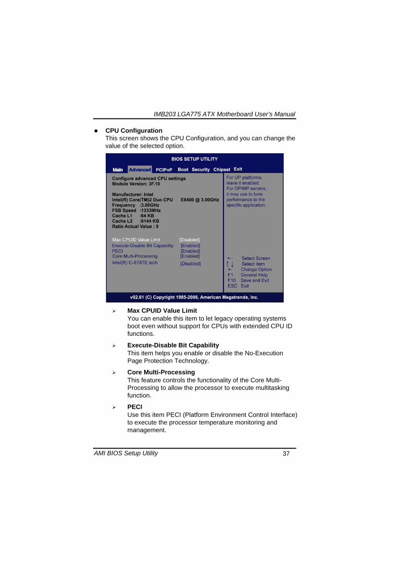
IMB203 LGA775 ATX Motherboard Userrsquos Manual
AMI BIOS Setup Utility 37
CPU Configuration This screen shows the CPU Configuration and you can change the value of the selected option
Max CPUID Value Limit
You can enable this item to let legacy operating systems boot even without support for CPUs with extended CPU ID functions
Execute-Disable Bit Capability This item helps you enable or disable the No-Execution Page Protection Technology
Core Multi-Processing This feature controls the functionality of the Core Multi-Processing to allow the processor to execute multitasking function
PECI Use this item PECI (Platform Environment Control Interface) to execute the processor temperature monitoring and management
IMB203 LGA775 ATX Motherboard Userrsquos Manual
AMI BIOS Setup Utility 38
Intel (R) C-STATE tech Use this item to enable or disable the C-State technology
IDE Configuration You can use this screen to select options for the IDE Configuration and change the value of the selected option A description of the selected item appears on the right side of the screen For items marked with ldquo rdquo please press ltEntergt for more options
SATA1 Configuration
Use this item to control the onboard SATA controller Here are the options for your selection Compatible Disabled and Enhanced
Configure SATA1 as Use this item to choose the SATA operation mode Here are the options for your selection IDE and AHCI
SATA2 Configuration Use this item to control the onboard SATA controller Here are the options for your selection Enhanced and Disabled
IMB203 LGA775 ATX Motherboard Userrsquos Manual
AMI BIOS Setup Utility 39
PrimarySecondaryThird IDE Master Select one of the hard disk drives to configure IDE devices installed in the system by pressing ltEntergt for more options
Fifth IDE Master Select one of the hard disk drives to configure IDE devices installed in the system by pressing ltEntergt for more options
IMB203 LGA775 ATX Motherboard Userrsquos Manual
AMI BIOS Setup Utility 40
SuperIO Configuration You can use this screen to select options for the SuperIO Configuration and change the value of the selected option A description of the selected item appears on the right side of the screen
Serial Port1 Address
This option specifies the base IO port address and Interrupt Request address of serial port 1 The Optimal setting is 3F8IRQ4 The Fail-Safe default setting is Disabled
Serial Port2 Address This option specifies the base IO port address and Interrupt Request address of serial port 2 The Optimal setting is 2F8IRQ3 The Fail-Safe setting is Disabled
Parallel Port Address This item allows you to determine the IO address for onboard parallel port There are several options for your selection
Parallel Port Mode
IMB203 LGA775 ATX Motherboard Userrsquos Manual
AMI BIOS Setup Utility 41
Select an operating mode for the onboard parallel (printer) port
Parallel Port IRQ Use this item to set up the IRQ for onboard parallel port
Serial Port3 Address This item specifies the base IO port address and Interrupt Request address of serial port 3 The Optimal setting is 3E8IRQ11 The Fail-Safe default setting is Disabled
Serial Port3 IRQ This item specifies the IRQ used by the serial port 3
Serial Port4 Address This item specifies the base IO port address and Interrupt Request address of serial port 4 The Optimal setting is 2E8IRQ10 The Fail-Safe default setting is Disabled
Serial Port4 IRQ This item specifies the IRQ used by the serial port 4
IMB203 LGA775 ATX Motherboard Userrsquos Manual
AMI BIOS Setup Utility 42
Hardware Health Configuration This screen shows the Hardware Health Configuration and a description of the selected item appears on the right side of the screen
HW Health Configuration
This screen displays the temperature of CPU and System Fan Speed Vcore etc
IMB203 LGA775 ATX Motherboard Userrsquos Manual
AMI BIOS Setup Utility 43
ACPI Configuration You can use this screen to select options for the ACPI Configuration and change the value of the selected option A description of the selected item appears on the right side of the screen
General ACPI Configuration
Scroll to this item and press ltEntergt to view the General ACPI Configuration sub menu which contains General ACPI (Advanced Configuration and Power Management Interface) options for your configuration
Advanced ACPI Configuration Scroll to this item and press ltEntergt to view the Advanced ACPI Configuration sub menu which contains Advanced ACPI (Advanced Configuration and Power Management Interface) options for your configuration
Chipset ACPI Configuration Scroll to this item and press ltEntergt to view the Chipset ACPI Configuration sub menu which contains Chipset ACPI (Advanced Configuration and Power Management
IMB203 LGA775 ATX Motherboard Userrsquos Manual
AMI BIOS Setup Utility 44
Interface) options for your configuration AHCI Configuration
You can use this screen to select options for the AHCI Configuration and change the value of the selected option A description of the selected item appears on the right side of the screen
AHCI BIOS Support You can enable or disable this item to control the AHCI function of the SATA controller
IMB203 LGA775 ATX Motherboard Userrsquos Manual
AMI BIOS Setup Utility 45
Intel iAMT Configuration You can use this screen to select options for the Intel iAMT Configuration and change the value of the selected option A description of the selected item appears on the right side of the screen
Intel iAMT Support
You can enable this item to support iAMT (active management technology) function to follow up the procedure for the access to AMI program screen
Unconfigure iAMTME Use this item to unconfigure the iAMTME settings
IMB203 LGA775 ATX Motherboard Userrsquos Manual
AMI BIOS Setup Utility 46
Intel VT-d Configuration You can use this screen to select options for the Intel VT-d Configuration and change the value of the selected option A description of the selected item appears on the right side of the screen
Intel VT-d Virtualization Technology for Directed IO (VT-d) extends Virtualization Technology (VT) roadmap by providing hardware assists for virtualization solution VT-d can help end users improve security and reliability of the systems and also improve performance of IO devices in virtualized environment Here are the options for your selection Disabled and Enabled
IMB203 LGA775 ATX Motherboard Userrsquos Manual
AMI BIOS Setup Utility 47
Remote Access Configuration You can use this screen to select options for the Remote Access Configuration and change the value of the selected option A description of the selected item appears on the right side of the screen
Remote Access Use this item to enable or disable the Remote Access function
IMB203 LGA775 ATX Motherboard Userrsquos Manual
AMI BIOS Setup Utility 48
PCI Express Configuration This screen shows the PCI Express Configuration and you can change its value A description of the selected item appears on the right side of the screen
Active State Power-Management
Use this item to enable or disable the function of Active State Power-Management to provide you with lower power consumption The default setting is Disabled
IMB203 LGA775 ATX Motherboard Userrsquos Manual
AMI BIOS Setup Utility 49
Trusted Computing You can use this screen to select options for the Trusted Computing and change the value of the selected option A description of the selected item appears on the right side of the screen
TCGTPM SUPPORT Use this item to control the Trusted Platform Module (TPM) function
IMB203 LGA775 ATX Motherboard Userrsquos Manual
AMI BIOS Setup Utility 50
USB Configuration You can use this screen to select options for the USB Configuration and change the value of the selected option A description of the selected item appears on the right side of the screen
USB Functions
This item allows you to enable or disable USB functions
Legacy USB Support Use this item to enable or disable support for USB device on legacy operating system The default setting is Enabled
USB 20 Controller Mode Use this item to configure the USB 20 controller The default setting is HiSpeed
BIOS EHCI Hand-Off Enabling this item provide the support for operating systems without an EHCI hand-off feature The default setting is Enabled
IMB203 LGA775 ATX Motherboard Userrsquos Manual
AMI BIOS Setup Utility 51
IMB203 LGA775 ATX Motherboard Userrsquos Manual
AMI BIOS Setup Utility 52
55 PCI PnP Menu The PCI PnP menu allows users to change the advanced settings for PCIPnP devices
Clear NVRAM
Use this item to clear the data in the NVRAM (CMOS) Here are the options for your selection No and Yes
Plug amp Play OS When the setting is No Use this item to configure all the devices in the system When the setting is Yes and if you install a Plug and Play operating system the operating system configures the Plug and Play devices not required for boot The default setting is No
IMB203 LGA775 ATX Motherboard Userrsquos Manual
AMI BIOS Setup Utility 53
PCI Latency Timer This item controls how long a PCI device can hold the PCI bus before another takes over The longer the latency the longer the PCI device can retain control of the bus before handing it over to another PCI device There are several options for your selection
Allocate IRQ to PCI VGA This item allows BIOS to choose an IRQ to assign for the PCI VGA card Here are the options for your selection No and Yes
Palette Snooping Some old graphic controllers need to ldquosnooprdquo on the VGA palette and then map it to their display as a way to provide boot information and VGA compatibility This item allows such snooping to take place Here are the options for your selection Disabled and Enabled
PCI IDE BusMaster This item is a toggle for the built-in driver that allows the onboard IDE controller to perform DMA (Direct Memory Access) transfer Here are the options for your selection Disabled and Enabled
OffBoard PCIISA IDE Card This item is for any other non-onboard PCIISA IDE controller adapter There are several options for your selection
IRQ3457910111415 These items will allow you to assign each system interrupt a type depending on the type of device using the interrupt The option ldquoAvailablerdquo means the IRQ is going to assign automatically Here are the options for your selection Available and Reserved
DMA Channel 013567 These items will allow you to assign each DMA channel a type depending on the type of device using the channel The option ldquoAvailablerdquo means the channel is going to assign automatically Here are the options for your selection Available and Reserved
IMB203 LGA775 ATX Motherboard Userrsquos Manual
AMI BIOS Setup Utility 54
56 Boot Menu The Boot menu allows users to change boot options of the system You can select any of the items in the left frame of the screen to go to the sub menus
Boot Settings Configuration Boot Device Priority Removable Drives
For items marked with ldquo rdquo please press ltEntergt for more options
IMB203 LGA775 ATX Motherboard Userrsquos Manual
AMI BIOS Setup Utility 55
Boot Settings Configuration
Quick Boot
Enabling this item lets the BIOS skip some power on self tests (POST) The default setting is Enabled
AddOn ROM Display Mode This item selects the display mode for option ROM The default setting is Force BIOS
Boot Num-Lock Use this item to select the power-on state for the NumLock The default setting is On
PS2 Mouse Support This item determines if the BIOS should reserve IRQ12 for the PS2 mouse or allow other devices to make use of this IRQ Here are the options for your selection Auto Enabled and Disabled
Wait For lsquoF1rsquo Of Error If this item is enabled the system waits for the F1 key to be pressed when error occurs The default setting is Enabled
Hit lsquoDELrsquo Message Display If this item is enabled the system displays the message
IMB203 LGA775 ATX Motherboard Userrsquos Manual
AMI BIOS Setup Utility 56
ldquoPress DEL to run Setuprdquo during POST The default setting is Enabled
Interrupt 19 Capture If this item is enabled this function makes the option ROMs to trap Interrupt 19 The default setting is Disabled
Boot Device Priority The Boot Device Priority screen specifies the boot device priority sequence from the available devices
IMB203 LGA775 ATX Motherboard Userrsquos Manual
AMI BIOS Setup Utility 57
Removable Drives Use this screen to view the removable drives in the system The BIOS will attempt to arrange the removable drive boot sequence automatically You can also change the booting sequence
IMB203 LGA775 ATX Motherboard Userrsquos Manual
AMI BIOS Setup Utility 58
57 Security Menu The Security menu allows users to change the security settings for the system
Supervisor Password
This item indicates whether a supervisor password has been set If the password has been installed Installed displays If not Not Installed displays
User Password This item indicates whether a user password has been set If the password has been installed Installed displays If not Not Installed displays
Change Supervisor Password Select this option and press ltEntergt to access the sub menu You can use the sub menu to change the supervisor password
Change User Password Select this option and press ltEntergt to access the sub menu You can use the sub menu to change the user password
IMB203 LGA775 ATX Motherboard Userrsquos Manual
AMI BIOS Setup Utility 59
58 Chipset Menu The Chipset menu allows users to change the advanced chipset settings You can select any of the items in the left frame of the screen to go to the sub menus
North Bridge Configuration South Bridge Configuration ME Subsystem Configuration
For items marked with ldquo rdquo please press ltEntergt for more options
IMB203 LGA775 ATX Motherboard Userrsquos Manual
AMI BIOS Setup Utility 60
North Bridge Configuration
Memory Remap Feature
Use this item to enable or disable the remapping of the overlapped PCI memory above the total physical memory Only 64-bit OS supports this function
DRAM Frequency This item allows you to control the Memory Clock
Configure DRAM Timing by SPD This item can enable or disable DRAM timing by SPD (Serial Presence Detect) device which is a small EEPROM chip on the memory module containing important information about the module speed size addressing mode and various parameters
Memory Hole You can reserve this area of system memory for ISA adapter ROM When this area is reserved it cannot be cached Check the user information of peripherals that need to use this area o f system memory for the memory requirements Here are the options Disabled and 15M-16M
IMB203 LGA775 ATX Motherboard Userrsquos Manual
AMI BIOS Setup Utility 61
Initiate Graphic Adapter When using multiple graphics cards this item can select which graphics controller to be the primary display device during boot
IGD Graphics Mode Select This item allows you to select the amount of system memory used by the internal graphics device
PEG Port ConfigurationPEG Port This item is a toggle to enable or disable the PCI Express port Here are the options for your selection Auto and Disabled
Video Function Configuration Press ltEntergt for the sub-menu for setting up video function
IMB203 LGA775 ATX Motherboard Userrsquos Manual
AMI BIOS Setup Utility 62
South Bridge Configuration
GbE Wake Up From S5 This item specifies whether the system will be awakened from the S5 power
HDA Controller This item allows you to enable or disable the HD audio support
Restore on AC Power Loss This item can control how the PC will behave once power is restored following a power outage or other unexpected shutdown
PCIE Port Configuration This item allows you to set or disable the PCI Express Ports
IMB203 LGA775 ATX Motherboard Userrsquos Manual
AMI BIOS Setup Utility 63
ME Subsystem Configuration
It is strongly recommended that you do not modify these options unless you are an advanced user
IMB203 LGA775 ATX Motherboard Userrsquos Manual
AMI BIOS Setup Utility 64
59 Exit Menu The Exit menu allows users to load your system configuration with optimal or failsafe default values
Save Changes and Exit
When you have completed the system configuration changes select this option to leave Setup and reboot the computer so the new system configuration parameters can take effect Select Save Changes and Exit from the Exit menu and press ltEntergt Select Ok to save changes and exit
Discard Changes and Exit Select this option to quit Setup without making any permanent changes to the system configuration Select Discard Changes and Exit from the Exit menu and press ltEntergt Select Ok to discard changes and exit
Load Optimal Defaults It automatically sets all Setup options to a complete set of default settings when you select this option The Optimal settings are designed for maximum system performance but may not work best for all computer applications In particular do not use the Optimal Setup options if your
IMB203 LGA775 ATX Motherboard Userrsquos Manual
AMI BIOS Setup Utility 65
computer is experiencing system configuration problems Select Load Optimal Defaults from the Exit menu and press ltEntergt
Load Fail-Safe Defaults It automatically sets all Setup options to a complete set of default settings when you select this option The Fail-Safe settings are designed for maximum system stability but not maximum performance Select the Fail-Safe Setup options if your computer is experiencing system configuration problems Select Load Fail-Safe Defaults from the Exit menu and press ltEntergt Select Ok to load Fail-Safe defaults
IMB203 LGA775 ATX Motherboard Userrsquos Manual
AMI BIOS Setup Utility 66
MEMO
IMB203 LGA775 ATX Motherboard Userrsquos Manual
Installation of Drivers 67
CHPATER 6 INSTALLATION OF DRIVERS
The device drivers are located on the Product Information CD-ROM that comes with the IMB203 Series package The auto-run function of drivers will guide you to install the utilities and device drivers under a Windows system You can follow the onscreen instructions to install these devices
Chipse VGA LAN Audio iAMT MEI
61 Installing Chipset Driver 1 Run the SETUPEXE program from the driver directory in
your driver CD Click ldquoNextrdquo to next step
IMB203 LGA775 ATX Motherboard Userrsquos Manual
Installation of Drivers 68
2 An Intelreg License Agreement appears to show you the important information Click ldquoYesrdquo to next step
3 Refer to the Readme file below to view the system requirements and installation information
IMB203 LGA775 ATX Motherboard Userrsquos Manual
Installation of Drivers 69
3-1 Please wait while running the following setup operations
3-2 Please wait while running the following setup operations
IMB203 LGA775 ATX Motherboard Userrsquos Manual
Installation of Drivers 70
4 Click ldquoFinishrdquo to complete the setup process
5 You will be asked to reboot your computer when the installation is completed Please click ldquoYes I want to restart my computer nowrdquo if you donrsquot need to install any other drivers Otherwise please click ldquoNo I will restart my computer laterrdquo and go on next step
IMB203 LGA775 ATX Motherboard Userrsquos Manual
Installation of Drivers 71
62 Installing VGA Driver 1 Run the SETUPEXE program from the driver directory in
your driver CD Click ldquoNextrdquo to next step
2 An Intelreg License Agreement appears to show you the
important information Click ldquoYesrdquo to next step
IMB203 LGA775 ATX Motherboard Userrsquos Manual
Installation of Drivers 72
3 The message of Readme File Information appears to show you the system requirements and installation information Please click ldquoNextrdquo
4 Please wait while running the following setup operations
When this message appears please click ldquoNextrdquo
IMB203 LGA775 ATX Motherboard Userrsquos Manual
Installation of Drivers 73
5 Click ldquoFinishrdquo to complete the setup process
6 You will be asked to reboot your computer when the installation is completed Please click ldquoYes I want to restart my computer nowrdquo if you donrsquot need to install any other drivers Otherwise please click ldquoNo I will restart my computer laterrdquo and click ldquoFinishrdquo to complete the installation
IMB203 LGA775 ATX Motherboard Userrsquos Manual
Installation of Drivers 74
63 Installing LAN Driver
11 Run the InstallShield Wizard for Network Connections from
the driver directory in your driver CD Click ldquoNextrdquo to next step
IMB203 LGA775 ATX Motherboard Userrsquos Manual
Installation of Drivers 75
12 An Intelreg License Agreement appears to show you the important information Click ldquoYesrdquo to next step
13 A Setup Options window appears that you can select the
program features you want to install
IMB203 LGA775 ATX Motherboard Userrsquos Manual
Installation of Drivers 76
2 Click ldquoInstallrdquo to start the installation
3 Please wait while running the following installation operation
IMB203 LGA775 ATX Motherboard Userrsquos Manual
Installation of Drivers 77
4 Click ldquoFinishrdquo to complete the installation
Note The Driver item [Wake on Directed Packet] default is Enabled under Windows Vista
格式化 字型 (符號) Arial
格式化 字型 (符號) Arial
格式化 字型 斜體 字型色彩 黑色 (符號) Arial 非加寬 緊縮
格式化 字型 斜體 字型色彩 黑色 (符號) Arial 非加寬 緊縮
格式化 字型 (符號) Arial 非加寬 緊縮
IMB203 LGA775 ATX Motherboard Userrsquos Manual
Installation of Drivers 78
64 Installing AUDIO Driver 1 Run the InstallShield Wizard for Realtek High Definition
Audio Driver from the driver directory in your driver CD Click ldquoNextrdquo to next step
IMB203 LGA775 ATX Motherboard Userrsquos Manual
Installation of Drivers 79
2 Click ldquoInstallrdquo to start the installation and wait while running the installation operation
3 Click ldquoFinishrdquo to complete the installation
IMB203 LGA775 ATX Motherboard Userrsquos Manual
Installation of Drivers 80
65 Installing iAMT (Active Management Technology) Driver
Note You must download and properly install the required NET version 35 provided from a separate downloading of the actual FimwareTools kit releases posted on VIP prior to loading the MEILMS Driver stack
651 LMS_SOL Setup
1 Run the setup program to install Intelreg Active Management Technology onto your computer It is strongly recommended that you exit all programs before continuing Click ldquoNextrdquo to next step
格式化 字型 (符號) Arial
格式化 字型 (符號) Arial 非加寬 緊縮
IMB203 LGA775 ATX Motherboard Userrsquos Manual
Installation of Drivers 81
2 An Intelreg license agreement appears that you need to continue the setup program by clicking ldquoYesrdquo to accept the terms
IMB203 LGA775 ATX Motherboard Userrsquos Manual
Installation of Drivers 82
3 Refer to the Readme file below to view the system requirements and installation information Click ldquoNextrdquo to next setup
4 Please wait while running the following installation operation
IMB203 LGA775 ATX Motherboard Userrsquos Manual
Installation of Drivers 83
5 Click ldquoFinishrdquo to complete the installation
IMB203 LGA775 ATX Motherboard Userrsquos Manual
Installation of Drivers 84
652 LMS_SOL_IS Setup
1 Run the setup program to install Intelreg Active Management Technology onto your computer It is strongly recommended that you exit all programs before continuing Click ldquoNextrdquo to next step
IMB203 LGA775 ATX Motherboard Userrsquos Manual
Installation of Drivers 85
2 An Intelreg license agreement appears that you need to continue the setup program by clicking ldquoYesrdquo to accept the terms
IMB203 LGA775 ATX Motherboard Userrsquos Manual
Installation of Drivers 86
3 Refer to the Readme file below to view the system requirements and installation information Click ldquoNextrdquo to next setup
4 Please wait while running the following installation operation
IMB203 LGA775 ATX Motherboard Userrsquos Manual
Installation of Drivers 87
5 Click ldquoFinishrdquo to complete the installation
IMB203 LGA775 ATX Motherboard Userrsquos Manual
Installation of Drivers 88
66 Installing MEI (Management Engine Interface) Driver
Note You must download and properly install the required NET version 35 provided from a separate downloading of the actual FimwareTools kit releases posted on VIP prior to loading the MEILMS Driver stack
1 Run the setup program to install Intelreg Management Engine
Interface onto your computer It is strongly recommended that you exit all programs before continuing Click ldquoNextrdquo to next step
格式化 字型 (符號) Arial
格式化 字型 (符號) Arial 非加寬 緊縮
IMB203 LGA775 ATX Motherboard Userrsquos Manual
Installation of Drivers 89
2 An Intelreg license agreement appears that you need to continue the setup program by clicking ldquoYesrdquo to accept the terms
IMB203 LGA775 ATX Motherboard Userrsquos Manual
Installation of Drivers 90
3 Refer to the Readme file below to view the system requirements and installation information Click ldquoNextrdquo to next setup
4 Please wait while running the following installation operation
IMB203 LGA775 ATX Motherboard Userrsquos Manual
Installation of Drivers 91
5 Click ldquoFinishrdquo to complete the installation
IMB203 LGA775 ATX Motherboard Userrsquos Manual
Installation of Drivers 92
MEMO
IMB203 LGA775 ATX Motherboard Userrsquos Manual
Watchdog Timer 93
APPENDIX A WATCHDOG TIMER
Watchdog Timer Setting After the system stops working for a while it can be auto-reset by the Watchdog Timer The integrated Watchdog Timer can be set up in the system reset mode by program
Using the Watchdog Function Start darr Un-Lock WDT O 2E 87 Un-lock super IO
O 2E 87 Un-lock super IO darr Set WDT Function O 2E 2D O 2F 20 Select Logic device O 2E 07 O 2F 08 darr Activate WDT O 2E 30
O 2F 01 Set Second or Minute O 2E F5
O 2F N N=00 or 08(See below table) darr Set base timer O 2E F6
O 2F M=000102hellipFF(Hex) Value=0 to 255 darr WDT counting
re-set timer O 2E F6
O 2F M M=000102hellipFF(See below table) darr
格式化
格式化 項目符號及編號
格式化 項目符號及編號
格式化 字型 8 點 字型色彩黑色
格式化 字型 8 點 字型色彩黑色
格式化 定位點 1257 字元左 + 不在 1012 字元 + 1386字元
格式化 字型 8 點 字型色彩黑色
格式化 定位點 1257 字元左 + 不在 134 字元 + 1362字元
格式化 字型色彩 黑色
格式化 字型色彩 黑色
刪除
IMB203 LGA775 ATX Motherboard Userrsquos Manual
Watchdog Timer 94
IF No re-set timer WDT time-out generate RESET IF to disable WDT O 2E 30
O 2F 00 Can be disable at any time
N=00
M= 00h Time-out Disable 01h Time-out occurs after 1 second 02h Time-out occurs after 2 second 03h Time-out occurs after 3 second helliphelliphelliphelliphelliphelliphelliphelliphellip FFh Time-out occurs after 255 second
N=08
M= 00h Time-out Disable 01h Time-out occurs after 1 minute 02h Time-out occurs after 2 minutes 03h Time-out occurs after 3 minutes helliphelliphelliphelliphelliphelliphelliphelliphellip
FFh Time-out occurs after 255 minutes
格式化 字型色彩 黑色
格式化 字型色彩 黑色
IMB203 LGA775 ATX Motherboard Userrsquos Manual
PCI IRQ Routing 95
APPENDIX B PCI IRQ ROUTING
PICMG PCI IRQ Routing
Device ID Slot Int
PCI Slot 0 31 0 BCDA PCI Slot 1 30 1 CDAB PCI Slot 2 29 2 DABC PCI Slot 3 28 3 ABCD
IMB203 LGA775 ATX Motherboard Userrsquos Manual
PCI IRQ Routing 96
MEMO
IMB203 LGA775 ATX Motherboard Userrsquos Manual
Configuring SATA for RAID Function 97
APPENDIX C CONFIGURING SATA FOR RAID
FUNCTION
Configuring SATA Hard Drive(s) for RAID Function (Controller IntelregICH10DODO DH only) Please follow up the steps below to configure SATA hard drive(s) (1) Install SATA hard drive(s) in your system (2) Enter the BIOS Setup to configure SATA controller mode and boot
sequence (3) Configure RAID by the RAID BIOS (4) Install the SATA controller driver during the OS installation Before you begin the SATA configuration please prepare (a) Two SATA hard drives (to ensure optimal performance it is
recommended that you use two hard drives with identical model and capacity) If you do not want to create RAID with the SATA controller you may prepare only one hard drive
(b) An empty formatted floppy disk (c) Windows XP setup disk (1) Installing SATA hard drive(s) in your system
Connect one end of the SATA signal cable to the rear of the SATA hard drive and the other end to available SATA port(s) on the board Then connect the power connector of power supply to the hard drive
(2) Configuring SATA controller mode and boot sequence by the BIOS Setup You have to make sure whether the SATA controller is configured correctly by system BIOS Setup and set up BIOS boot sequence for the SATA hard drive(s)
IMB203 LGA775 ATX Motherboard Userrsquos Manual
Configuring SATA for RAID Function 98
(2)-1-1 Turn on your system and then press the Del button to enter BIOS Setup during running POST (Power-On Self Test) If you want to create RAID just go to the Advanced Settings menuIDE configuration select the Configure SATA1 as and press ltEntergt for more options
IMB203 LGA775 ATX Motherboard Userrsquos Manual
Configuring SATA for RAID Function 99
(2)-1-2 A list of options appears please select RAID
IMB203 LGA775 ATX Motherboard Userrsquos Manual
Configuring SATA for RAID Function 100
(2)-2 Set CDROM for First Boot Device under the Boot Settings menu to boot CD-ROM after system restarts
(2)-3 Save and exit the BIOS Setup
IMB203 LGA775 ATX Motherboard Userrsquos Manual
Configuring SATA for RAID Function 101
(3) Configuring RAID by the RAID BIOS Enter the RAID BIOS setup utility to configure a RAID array Skip this step and proceed to Section 4 if you do not want to create a RAID (3)-1 After the POST memory testing and before the operating
system booting a message Press ltCtrl-Igt to enter Configuration Utility shows up accordingly press ltCTRL+ Igt to enter the RAID BIOS setup utility
(3)-2 After you press ltCTRL+ Igt the Create RAID Volume screen will appear If you want to create a RAID array select the Create RAID Volume option in the Main Menu and press ENTER
IMB203 LGA775 ATX Motherboard Userrsquos Manual
Configuring SATA for RAID Function 102
(3)-3-1 After entering the CREATE VOLUME MENU screen you can type the disk array name with 1~16 letters (letters cannot be special characters) in the item ldquoNamerdquo
(3)-3-2 When finished press ENTER to select a RAID level There are three RAID levels RAID0 RAID1 and RAID5 amp RAID10 Select a RAID level and press ENTER
IMB203 LGA775 ATX Motherboard Userrsquos Manual
Configuring SATA for RAID Function 103
(3)-4 Set the stripe block size The KB is the standard unit of stripe block size The stripe block size can be 4KB to 128KB After the setting press ENTER for the array capacity
(3)-5 After setting all the items on the menu select Create Volume
and press ENTER to start creating the RAID array
IMB203 LGA775 ATX Motherboard Userrsquos Manual
Configuring SATA for RAID Function 104
(3)-6 When prompting the confirmation press ldquoYldquo to create this volume or ldquoNldquo to cancel the creation
After the creation is completed you can see detailed information about the RAID Array in the DISKVOLUME INFORMATION section including RAID mode disk block size disk name and disk capacity etc
IMB203 LGA775 ATX Motherboard Userrsquos Manual
Configuring SATA for RAID Function 105
Delete RAID Volume If you want to delete a RAID volume select the Delete RAID Volume option in Main Menu Press ENTER and follow on-screen instructions
Please press [ESC] to exit the RAID BIOS utility Now you can proceed to install a SATA driver controller and the operating system
IMB203 LGA775 ATX Motherboard Userrsquos Manual
Configuring SATA for RAID Function 106
(4) Making a SATA Driver Disk To install the operating system onto a serial ATA hard disk successfully you need to install the SATA controller driver during the OS installation Without the driver the hard disk may not be recognized during the Windows setup process First of all please format a blank floppy disk Secondly follow up these steps below to produce a SATA driver disk Users can insert the Driver CD and the formatted blank floppy disk in another system And then please copy all of file of the f6flpy32 folder in the Driver CD to a floppy disk Note Please copy all of file of the f6flpy64 folder if installing 64-bit
Windows Operating System
IMB203 LGA775 ATX Motherboard Userrsquos Manual
Configuring SATA for RAID Function 107
(5) Installing the SATA controller driver during the OS installation Now the SATA driver disk is ready and BIOS settings configured you can proceed to install Windows 2000XP onto your SATA hard drive using the SATA driver Here is an example for Windows XP installation (5)-1 Restart your system to boot the Windows 2000XP Setup disk
and press F6 button as soon as you see the message Press F6 if you need to install a 3rd party SCSI or RAID driver After pressing the F6 button there will be a few moments for some files being loaded before next screen appears
IMB203 LGA775 ATX Motherboard Userrsquos Manual
Configuring SATA for RAID Function 108
(5)-2 When you see the screen below insert the floppy disk containing the SATA driver and press ldquoSrdquo
(5)-3 If the Setup correctly recognizes the driver of the floppy disk
a controller menu will appear below Use the ARROW keys to select Intel(R) ICH8RICH9RICH10RDO SATA RAID Controller and press ENTER Then it will begin to load the SATA driver from the floppy disk
IMB203 LGA775 ATX Motherboard Userrsquos Manual
Configuring SATA for RAID Function 109
Note If a message on the screen saying that one or some file(s) cannot be found please check the floppy disk or copy the correct SATA driver again from the driver CD
IMB203 LGA775 ATX Motherboard Userrsquos Manual
Configuring SATA for RAID Function 110
MEMO
IMB203 LGA775 ATX Motherboard Userrsquos Manual
iAMT Settings 111
APPENDIX D iAMT SETTINGS
The Intelreg Active Management Technology (Intelreg iAMT) has decreased a major barrier to IT efficiency that uses built-in platform capabilities and popular third-party management and security applications to allow IT a better discovering healing and protection their networked computing assets In order to utilize Intel iAMT you must enter the ME BIOS (CTRL + P during system startup) change the ME BIOS password and then select ldquoIntelreg iAMTrdquo as the manageability feature
D1 Entering MEBx 1 You must go to BIOS TO start iAMT function 2 Exit from BIOS after starting iAMT and press Ctrl+P to enter MEBx Setting
It is better to press Ctrl+P before the screen popping out
格式化
IMB203 LGA775 ATX Motherboard Userrsquos Manual
iAMT Settings 112
D2 Set amp Change Password 1 You will be asked to set a password when first log in The default
password is lsquoadminrsquo
2 You will be asked to change the password before setting ME
Change Password
IMB203 LGA775 ATX Motherboard Userrsquos Manual
iAMT Settings 113
3 You must confirm your new password while revising (as Remark 1)
Remark 1 The new password must contain (example 11qqQQ) (default value)
Eight characters
One upper case
One lower case
One number
One special symbol such as $ or
( excepted)
Underline ( _ ) and space are valid characters for password but they wonrsquot make higher complexity
IMB203 LGA775 ATX Motherboard Userrsquos Manual
iAMT Settings 114
D3 Intelreg iAMT Settings 1 Select Intelreg iAMT Configuration and press ltENTERgt
2 Key in the Host Name If Intelreg iAMT set to lsquoDHCPlsquo the Host name must be identical to the operating system mechanic
IMB203 LGA775 ATX Motherboard Userrsquos Manual
iAMT Settings 115
3 Select TCPIP to get into Network interface and set it to lsquoENABLEDrsquo into DHCP Mode and set it to lsquoDISABLEDrsquo (as Remark 2) into Domain name and set the Intel Management Engine domain name such as lsquoAMTintelcomrsquo
(3-1)
(3-2)
IMB203 LGA775 ATX Motherboard Userrsquos Manual
iAMT Settings 116
Remark 2 DHCP Mode lsquoDISABLEDlsquo if DHCP Mode is disabled you can make the following settings
IP address
Subnet mask
IMB203 LGA775 ATX Motherboard Userrsquos Manual
iAMT Settings 117
Default Gateway address
Preferred DNS address
IMB203 LGA775 ATX Motherboard Userrsquos Manual
iAMT Settings 118
Alternate DNS address
Domain name
4 Exit from MEBx after completing the iAMT settings
IMB203 LGA775 ATX Motherboard Userrsquos Manual
iAMT Settings 119
D4 iAMT Web Console 1 From a web browser please type http(IP ADDRESS)16992
which connects to iAMT Web Example http1014021416992
2 To log on you will be required to type in username and password
for access to the Web
USER admin (default value)
PASS (MEBx password)
IMB203 LGA775 ATX Motherboard Userrsquos Manual
iAMT Settings 120
3 Enter the iAMT Web
4 Click Remote Control and select commands on the right side
IMB203 LGA775 ATX Motherboard Userrsquos Manual
iAMT Settings 121
5 When you have finished using the iAMT Web console close the Web browser
IMB203 LGA775 ATX Motherboard Userrsquos Manual
iAMT Settings 122
MEMO
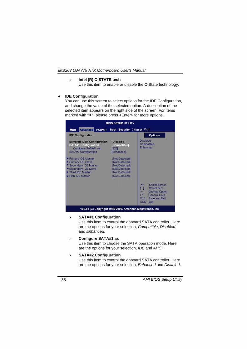
IMB203 LGA775 ATX Motherboard Userrsquos Manual
AMI BIOS Setup Utility 39
PrimarySecondaryThird IDE Master Select one of the hard disk drives to configure IDE devices installed in the system by pressing ltEntergt for more options
Fifth IDE Master Select one of the hard disk drives to configure IDE devices installed in the system by pressing ltEntergt for more options
IMB203 LGA775 ATX Motherboard Userrsquos Manual
AMI BIOS Setup Utility 40
SuperIO Configuration You can use this screen to select options for the SuperIO Configuration and change the value of the selected option A description of the selected item appears on the right side of the screen
Serial Port1 Address
This option specifies the base IO port address and Interrupt Request address of serial port 1 The Optimal setting is 3F8IRQ4 The Fail-Safe default setting is Disabled
Serial Port2 Address This option specifies the base IO port address and Interrupt Request address of serial port 2 The Optimal setting is 2F8IRQ3 The Fail-Safe setting is Disabled
Parallel Port Address This item allows you to determine the IO address for onboard parallel port There are several options for your selection
Parallel Port Mode
IMB203 LGA775 ATX Motherboard Userrsquos Manual
AMI BIOS Setup Utility 41
Select an operating mode for the onboard parallel (printer) port
Parallel Port IRQ Use this item to set up the IRQ for onboard parallel port
Serial Port3 Address This item specifies the base IO port address and Interrupt Request address of serial port 3 The Optimal setting is 3E8IRQ11 The Fail-Safe default setting is Disabled
Serial Port3 IRQ This item specifies the IRQ used by the serial port 3
Serial Port4 Address This item specifies the base IO port address and Interrupt Request address of serial port 4 The Optimal setting is 2E8IRQ10 The Fail-Safe default setting is Disabled
Serial Port4 IRQ This item specifies the IRQ used by the serial port 4
IMB203 LGA775 ATX Motherboard Userrsquos Manual
AMI BIOS Setup Utility 42
Hardware Health Configuration This screen shows the Hardware Health Configuration and a description of the selected item appears on the right side of the screen
HW Health Configuration
This screen displays the temperature of CPU and System Fan Speed Vcore etc
IMB203 LGA775 ATX Motherboard Userrsquos Manual
AMI BIOS Setup Utility 43
ACPI Configuration You can use this screen to select options for the ACPI Configuration and change the value of the selected option A description of the selected item appears on the right side of the screen
General ACPI Configuration
Scroll to this item and press ltEntergt to view the General ACPI Configuration sub menu which contains General ACPI (Advanced Configuration and Power Management Interface) options for your configuration
Advanced ACPI Configuration Scroll to this item and press ltEntergt to view the Advanced ACPI Configuration sub menu which contains Advanced ACPI (Advanced Configuration and Power Management Interface) options for your configuration
Chipset ACPI Configuration Scroll to this item and press ltEntergt to view the Chipset ACPI Configuration sub menu which contains Chipset ACPI (Advanced Configuration and Power Management
IMB203 LGA775 ATX Motherboard Userrsquos Manual
AMI BIOS Setup Utility 44
Interface) options for your configuration AHCI Configuration
You can use this screen to select options for the AHCI Configuration and change the value of the selected option A description of the selected item appears on the right side of the screen
AHCI BIOS Support You can enable or disable this item to control the AHCI function of the SATA controller
IMB203 LGA775 ATX Motherboard Userrsquos Manual
AMI BIOS Setup Utility 45
Intel iAMT Configuration You can use this screen to select options for the Intel iAMT Configuration and change the value of the selected option A description of the selected item appears on the right side of the screen
Intel iAMT Support
You can enable this item to support iAMT (active management technology) function to follow up the procedure for the access to AMI program screen
Unconfigure iAMTME Use this item to unconfigure the iAMTME settings
IMB203 LGA775 ATX Motherboard Userrsquos Manual
AMI BIOS Setup Utility 46
Intel VT-d Configuration You can use this screen to select options for the Intel VT-d Configuration and change the value of the selected option A description of the selected item appears on the right side of the screen
Intel VT-d Virtualization Technology for Directed IO (VT-d) extends Virtualization Technology (VT) roadmap by providing hardware assists for virtualization solution VT-d can help end users improve security and reliability of the systems and also improve performance of IO devices in virtualized environment Here are the options for your selection Disabled and Enabled
IMB203 LGA775 ATX Motherboard Userrsquos Manual
AMI BIOS Setup Utility 47
Remote Access Configuration You can use this screen to select options for the Remote Access Configuration and change the value of the selected option A description of the selected item appears on the right side of the screen
Remote Access Use this item to enable or disable the Remote Access function
IMB203 LGA775 ATX Motherboard Userrsquos Manual
AMI BIOS Setup Utility 48
PCI Express Configuration This screen shows the PCI Express Configuration and you can change its value A description of the selected item appears on the right side of the screen
Active State Power-Management
Use this item to enable or disable the function of Active State Power-Management to provide you with lower power consumption The default setting is Disabled
IMB203 LGA775 ATX Motherboard Userrsquos Manual
AMI BIOS Setup Utility 49
Trusted Computing You can use this screen to select options for the Trusted Computing and change the value of the selected option A description of the selected item appears on the right side of the screen
TCGTPM SUPPORT Use this item to control the Trusted Platform Module (TPM) function
IMB203 LGA775 ATX Motherboard Userrsquos Manual
AMI BIOS Setup Utility 50
USB Configuration You can use this screen to select options for the USB Configuration and change the value of the selected option A description of the selected item appears on the right side of the screen
USB Functions
This item allows you to enable or disable USB functions
Legacy USB Support Use this item to enable or disable support for USB device on legacy operating system The default setting is Enabled
USB 20 Controller Mode Use this item to configure the USB 20 controller The default setting is HiSpeed
BIOS EHCI Hand-Off Enabling this item provide the support for operating systems without an EHCI hand-off feature The default setting is Enabled
IMB203 LGA775 ATX Motherboard Userrsquos Manual
AMI BIOS Setup Utility 51
IMB203 LGA775 ATX Motherboard Userrsquos Manual
AMI BIOS Setup Utility 52
55 PCI PnP Menu The PCI PnP menu allows users to change the advanced settings for PCIPnP devices
Clear NVRAM
Use this item to clear the data in the NVRAM (CMOS) Here are the options for your selection No and Yes
Plug amp Play OS When the setting is No Use this item to configure all the devices in the system When the setting is Yes and if you install a Plug and Play operating system the operating system configures the Plug and Play devices not required for boot The default setting is No
IMB203 LGA775 ATX Motherboard Userrsquos Manual
AMI BIOS Setup Utility 53
PCI Latency Timer This item controls how long a PCI device can hold the PCI bus before another takes over The longer the latency the longer the PCI device can retain control of the bus before handing it over to another PCI device There are several options for your selection
Allocate IRQ to PCI VGA This item allows BIOS to choose an IRQ to assign for the PCI VGA card Here are the options for your selection No and Yes
Palette Snooping Some old graphic controllers need to ldquosnooprdquo on the VGA palette and then map it to their display as a way to provide boot information and VGA compatibility This item allows such snooping to take place Here are the options for your selection Disabled and Enabled
PCI IDE BusMaster This item is a toggle for the built-in driver that allows the onboard IDE controller to perform DMA (Direct Memory Access) transfer Here are the options for your selection Disabled and Enabled
OffBoard PCIISA IDE Card This item is for any other non-onboard PCIISA IDE controller adapter There are several options for your selection
IRQ3457910111415 These items will allow you to assign each system interrupt a type depending on the type of device using the interrupt The option ldquoAvailablerdquo means the IRQ is going to assign automatically Here are the options for your selection Available and Reserved
DMA Channel 013567 These items will allow you to assign each DMA channel a type depending on the type of device using the channel The option ldquoAvailablerdquo means the channel is going to assign automatically Here are the options for your selection Available and Reserved
IMB203 LGA775 ATX Motherboard Userrsquos Manual
AMI BIOS Setup Utility 54
56 Boot Menu The Boot menu allows users to change boot options of the system You can select any of the items in the left frame of the screen to go to the sub menus
Boot Settings Configuration Boot Device Priority Removable Drives
For items marked with ldquo rdquo please press ltEntergt for more options
IMB203 LGA775 ATX Motherboard Userrsquos Manual
AMI BIOS Setup Utility 55
Boot Settings Configuration
Quick Boot
Enabling this item lets the BIOS skip some power on self tests (POST) The default setting is Enabled
AddOn ROM Display Mode This item selects the display mode for option ROM The default setting is Force BIOS
Boot Num-Lock Use this item to select the power-on state for the NumLock The default setting is On
PS2 Mouse Support This item determines if the BIOS should reserve IRQ12 for the PS2 mouse or allow other devices to make use of this IRQ Here are the options for your selection Auto Enabled and Disabled
Wait For lsquoF1rsquo Of Error If this item is enabled the system waits for the F1 key to be pressed when error occurs The default setting is Enabled
Hit lsquoDELrsquo Message Display If this item is enabled the system displays the message
IMB203 LGA775 ATX Motherboard Userrsquos Manual
AMI BIOS Setup Utility 56
ldquoPress DEL to run Setuprdquo during POST The default setting is Enabled
Interrupt 19 Capture If this item is enabled this function makes the option ROMs to trap Interrupt 19 The default setting is Disabled
Boot Device Priority The Boot Device Priority screen specifies the boot device priority sequence from the available devices
IMB203 LGA775 ATX Motherboard Userrsquos Manual
AMI BIOS Setup Utility 57
Removable Drives Use this screen to view the removable drives in the system The BIOS will attempt to arrange the removable drive boot sequence automatically You can also change the booting sequence
IMB203 LGA775 ATX Motherboard Userrsquos Manual
AMI BIOS Setup Utility 58
57 Security Menu The Security menu allows users to change the security settings for the system
Supervisor Password
This item indicates whether a supervisor password has been set If the password has been installed Installed displays If not Not Installed displays
User Password This item indicates whether a user password has been set If the password has been installed Installed displays If not Not Installed displays
Change Supervisor Password Select this option and press ltEntergt to access the sub menu You can use the sub menu to change the supervisor password
Change User Password Select this option and press ltEntergt to access the sub menu You can use the sub menu to change the user password
IMB203 LGA775 ATX Motherboard Userrsquos Manual
AMI BIOS Setup Utility 59
58 Chipset Menu The Chipset menu allows users to change the advanced chipset settings You can select any of the items in the left frame of the screen to go to the sub menus
North Bridge Configuration South Bridge Configuration ME Subsystem Configuration
For items marked with ldquo rdquo please press ltEntergt for more options
IMB203 LGA775 ATX Motherboard Userrsquos Manual
AMI BIOS Setup Utility 60
North Bridge Configuration
Memory Remap Feature
Use this item to enable or disable the remapping of the overlapped PCI memory above the total physical memory Only 64-bit OS supports this function
DRAM Frequency This item allows you to control the Memory Clock
Configure DRAM Timing by SPD This item can enable or disable DRAM timing by SPD (Serial Presence Detect) device which is a small EEPROM chip on the memory module containing important information about the module speed size addressing mode and various parameters
Memory Hole You can reserve this area of system memory for ISA adapter ROM When this area is reserved it cannot be cached Check the user information of peripherals that need to use this area o f system memory for the memory requirements Here are the options Disabled and 15M-16M
IMB203 LGA775 ATX Motherboard Userrsquos Manual
AMI BIOS Setup Utility 61
Initiate Graphic Adapter When using multiple graphics cards this item can select which graphics controller to be the primary display device during boot
IGD Graphics Mode Select This item allows you to select the amount of system memory used by the internal graphics device
PEG Port ConfigurationPEG Port This item is a toggle to enable or disable the PCI Express port Here are the options for your selection Auto and Disabled
Video Function Configuration Press ltEntergt for the sub-menu for setting up video function
IMB203 LGA775 ATX Motherboard Userrsquos Manual
AMI BIOS Setup Utility 62
South Bridge Configuration
GbE Wake Up From S5 This item specifies whether the system will be awakened from the S5 power
HDA Controller This item allows you to enable or disable the HD audio support
Restore on AC Power Loss This item can control how the PC will behave once power is restored following a power outage or other unexpected shutdown
PCIE Port Configuration This item allows you to set or disable the PCI Express Ports
IMB203 LGA775 ATX Motherboard Userrsquos Manual
AMI BIOS Setup Utility 63
ME Subsystem Configuration
It is strongly recommended that you do not modify these options unless you are an advanced user
IMB203 LGA775 ATX Motherboard Userrsquos Manual
AMI BIOS Setup Utility 64
59 Exit Menu The Exit menu allows users to load your system configuration with optimal or failsafe default values
Save Changes and Exit
When you have completed the system configuration changes select this option to leave Setup and reboot the computer so the new system configuration parameters can take effect Select Save Changes and Exit from the Exit menu and press ltEntergt Select Ok to save changes and exit
Discard Changes and Exit Select this option to quit Setup without making any permanent changes to the system configuration Select Discard Changes and Exit from the Exit menu and press ltEntergt Select Ok to discard changes and exit
Load Optimal Defaults It automatically sets all Setup options to a complete set of default settings when you select this option The Optimal settings are designed for maximum system performance but may not work best for all computer applications In particular do not use the Optimal Setup options if your
IMB203 LGA775 ATX Motherboard Userrsquos Manual
AMI BIOS Setup Utility 65
computer is experiencing system configuration problems Select Load Optimal Defaults from the Exit menu and press ltEntergt
Load Fail-Safe Defaults It automatically sets all Setup options to a complete set of default settings when you select this option The Fail-Safe settings are designed for maximum system stability but not maximum performance Select the Fail-Safe Setup options if your computer is experiencing system configuration problems Select Load Fail-Safe Defaults from the Exit menu and press ltEntergt Select Ok to load Fail-Safe defaults
IMB203 LGA775 ATX Motherboard Userrsquos Manual
AMI BIOS Setup Utility 66
MEMO
IMB203 LGA775 ATX Motherboard Userrsquos Manual
Installation of Drivers 67
CHPATER 6 INSTALLATION OF DRIVERS
The device drivers are located on the Product Information CD-ROM that comes with the IMB203 Series package The auto-run function of drivers will guide you to install the utilities and device drivers under a Windows system You can follow the onscreen instructions to install these devices
Chipse VGA LAN Audio iAMT MEI
61 Installing Chipset Driver 1 Run the SETUPEXE program from the driver directory in
your driver CD Click ldquoNextrdquo to next step
IMB203 LGA775 ATX Motherboard Userrsquos Manual
Installation of Drivers 68
2 An Intelreg License Agreement appears to show you the important information Click ldquoYesrdquo to next step
3 Refer to the Readme file below to view the system requirements and installation information
IMB203 LGA775 ATX Motherboard Userrsquos Manual
Installation of Drivers 69
3-1 Please wait while running the following setup operations
3-2 Please wait while running the following setup operations
IMB203 LGA775 ATX Motherboard Userrsquos Manual
Installation of Drivers 70
4 Click ldquoFinishrdquo to complete the setup process
5 You will be asked to reboot your computer when the installation is completed Please click ldquoYes I want to restart my computer nowrdquo if you donrsquot need to install any other drivers Otherwise please click ldquoNo I will restart my computer laterrdquo and go on next step
IMB203 LGA775 ATX Motherboard Userrsquos Manual
Installation of Drivers 71
62 Installing VGA Driver 1 Run the SETUPEXE program from the driver directory in
your driver CD Click ldquoNextrdquo to next step
2 An Intelreg License Agreement appears to show you the
important information Click ldquoYesrdquo to next step
IMB203 LGA775 ATX Motherboard Userrsquos Manual
Installation of Drivers 72
3 The message of Readme File Information appears to show you the system requirements and installation information Please click ldquoNextrdquo
4 Please wait while running the following setup operations
When this message appears please click ldquoNextrdquo
IMB203 LGA775 ATX Motherboard Userrsquos Manual
Installation of Drivers 73
5 Click ldquoFinishrdquo to complete the setup process
6 You will be asked to reboot your computer when the installation is completed Please click ldquoYes I want to restart my computer nowrdquo if you donrsquot need to install any other drivers Otherwise please click ldquoNo I will restart my computer laterrdquo and click ldquoFinishrdquo to complete the installation
IMB203 LGA775 ATX Motherboard Userrsquos Manual
Installation of Drivers 74
63 Installing LAN Driver
11 Run the InstallShield Wizard for Network Connections from
the driver directory in your driver CD Click ldquoNextrdquo to next step
IMB203 LGA775 ATX Motherboard Userrsquos Manual
Installation of Drivers 75
12 An Intelreg License Agreement appears to show you the important information Click ldquoYesrdquo to next step
13 A Setup Options window appears that you can select the
program features you want to install
IMB203 LGA775 ATX Motherboard Userrsquos Manual
Installation of Drivers 76
2 Click ldquoInstallrdquo to start the installation
3 Please wait while running the following installation operation
IMB203 LGA775 ATX Motherboard Userrsquos Manual
Installation of Drivers 77
4 Click ldquoFinishrdquo to complete the installation
Note The Driver item [Wake on Directed Packet] default is Enabled under Windows Vista
格式化 字型 (符號) Arial
格式化 字型 (符號) Arial
格式化 字型 斜體 字型色彩 黑色 (符號) Arial 非加寬 緊縮
格式化 字型 斜體 字型色彩 黑色 (符號) Arial 非加寬 緊縮
格式化 字型 (符號) Arial 非加寬 緊縮
IMB203 LGA775 ATX Motherboard Userrsquos Manual
Installation of Drivers 78
64 Installing AUDIO Driver 1 Run the InstallShield Wizard for Realtek High Definition
Audio Driver from the driver directory in your driver CD Click ldquoNextrdquo to next step
IMB203 LGA775 ATX Motherboard Userrsquos Manual
Installation of Drivers 79
2 Click ldquoInstallrdquo to start the installation and wait while running the installation operation
3 Click ldquoFinishrdquo to complete the installation
IMB203 LGA775 ATX Motherboard Userrsquos Manual
Installation of Drivers 80
65 Installing iAMT (Active Management Technology) Driver
Note You must download and properly install the required NET version 35 provided from a separate downloading of the actual FimwareTools kit releases posted on VIP prior to loading the MEILMS Driver stack
651 LMS_SOL Setup
1 Run the setup program to install Intelreg Active Management Technology onto your computer It is strongly recommended that you exit all programs before continuing Click ldquoNextrdquo to next step
格式化 字型 (符號) Arial
格式化 字型 (符號) Arial 非加寬 緊縮
IMB203 LGA775 ATX Motherboard Userrsquos Manual
Installation of Drivers 81
2 An Intelreg license agreement appears that you need to continue the setup program by clicking ldquoYesrdquo to accept the terms
IMB203 LGA775 ATX Motherboard Userrsquos Manual
Installation of Drivers 82
3 Refer to the Readme file below to view the system requirements and installation information Click ldquoNextrdquo to next setup
4 Please wait while running the following installation operation
IMB203 LGA775 ATX Motherboard Userrsquos Manual
Installation of Drivers 83
5 Click ldquoFinishrdquo to complete the installation
IMB203 LGA775 ATX Motherboard Userrsquos Manual
Installation of Drivers 84
652 LMS_SOL_IS Setup
1 Run the setup program to install Intelreg Active Management Technology onto your computer It is strongly recommended that you exit all programs before continuing Click ldquoNextrdquo to next step
IMB203 LGA775 ATX Motherboard Userrsquos Manual
Installation of Drivers 85
2 An Intelreg license agreement appears that you need to continue the setup program by clicking ldquoYesrdquo to accept the terms
IMB203 LGA775 ATX Motherboard Userrsquos Manual
Installation of Drivers 86
3 Refer to the Readme file below to view the system requirements and installation information Click ldquoNextrdquo to next setup
4 Please wait while running the following installation operation
IMB203 LGA775 ATX Motherboard Userrsquos Manual
Installation of Drivers 87
5 Click ldquoFinishrdquo to complete the installation
IMB203 LGA775 ATX Motherboard Userrsquos Manual
Installation of Drivers 88
66 Installing MEI (Management Engine Interface) Driver
Note You must download and properly install the required NET version 35 provided from a separate downloading of the actual FimwareTools kit releases posted on VIP prior to loading the MEILMS Driver stack
1 Run the setup program to install Intelreg Management Engine
Interface onto your computer It is strongly recommended that you exit all programs before continuing Click ldquoNextrdquo to next step
格式化 字型 (符號) Arial
格式化 字型 (符號) Arial 非加寬 緊縮
IMB203 LGA775 ATX Motherboard Userrsquos Manual
Installation of Drivers 89
2 An Intelreg license agreement appears that you need to continue the setup program by clicking ldquoYesrdquo to accept the terms
IMB203 LGA775 ATX Motherboard Userrsquos Manual
Installation of Drivers 90
3 Refer to the Readme file below to view the system requirements and installation information Click ldquoNextrdquo to next setup
4 Please wait while running the following installation operation
IMB203 LGA775 ATX Motherboard Userrsquos Manual
Installation of Drivers 91
5 Click ldquoFinishrdquo to complete the installation
IMB203 LGA775 ATX Motherboard Userrsquos Manual
Installation of Drivers 92
MEMO
IMB203 LGA775 ATX Motherboard Userrsquos Manual
Watchdog Timer 93
APPENDIX A WATCHDOG TIMER
Watchdog Timer Setting After the system stops working for a while it can be auto-reset by the Watchdog Timer The integrated Watchdog Timer can be set up in the system reset mode by program
Using the Watchdog Function Start darr Un-Lock WDT O 2E 87 Un-lock super IO
O 2E 87 Un-lock super IO darr Set WDT Function O 2E 2D O 2F 20 Select Logic device O 2E 07 O 2F 08 darr Activate WDT O 2E 30
O 2F 01 Set Second or Minute O 2E F5
O 2F N N=00 or 08(See below table) darr Set base timer O 2E F6
O 2F M=000102hellipFF(Hex) Value=0 to 255 darr WDT counting
re-set timer O 2E F6
O 2F M M=000102hellipFF(See below table) darr
格式化
格式化 項目符號及編號
格式化 項目符號及編號
格式化 字型 8 點 字型色彩黑色
格式化 字型 8 點 字型色彩黑色
格式化 定位點 1257 字元左 + 不在 1012 字元 + 1386字元
格式化 字型 8 點 字型色彩黑色
格式化 定位點 1257 字元左 + 不在 134 字元 + 1362字元
格式化 字型色彩 黑色
格式化 字型色彩 黑色
刪除
IMB203 LGA775 ATX Motherboard Userrsquos Manual
Watchdog Timer 94
IF No re-set timer WDT time-out generate RESET IF to disable WDT O 2E 30
O 2F 00 Can be disable at any time
N=00
M= 00h Time-out Disable 01h Time-out occurs after 1 second 02h Time-out occurs after 2 second 03h Time-out occurs after 3 second helliphelliphelliphelliphelliphelliphelliphelliphellip FFh Time-out occurs after 255 second
N=08
M= 00h Time-out Disable 01h Time-out occurs after 1 minute 02h Time-out occurs after 2 minutes 03h Time-out occurs after 3 minutes helliphelliphelliphelliphelliphelliphelliphelliphellip
FFh Time-out occurs after 255 minutes
格式化 字型色彩 黑色
格式化 字型色彩 黑色
IMB203 LGA775 ATX Motherboard Userrsquos Manual
PCI IRQ Routing 95
APPENDIX B PCI IRQ ROUTING
PICMG PCI IRQ Routing
Device ID Slot Int
PCI Slot 0 31 0 BCDA PCI Slot 1 30 1 CDAB PCI Slot 2 29 2 DABC PCI Slot 3 28 3 ABCD
IMB203 LGA775 ATX Motherboard Userrsquos Manual
PCI IRQ Routing 96
MEMO
IMB203 LGA775 ATX Motherboard Userrsquos Manual
Configuring SATA for RAID Function 97
APPENDIX C CONFIGURING SATA FOR RAID
FUNCTION
Configuring SATA Hard Drive(s) for RAID Function (Controller IntelregICH10DODO DH only) Please follow up the steps below to configure SATA hard drive(s) (1) Install SATA hard drive(s) in your system (2) Enter the BIOS Setup to configure SATA controller mode and boot
sequence (3) Configure RAID by the RAID BIOS (4) Install the SATA controller driver during the OS installation Before you begin the SATA configuration please prepare (a) Two SATA hard drives (to ensure optimal performance it is
recommended that you use two hard drives with identical model and capacity) If you do not want to create RAID with the SATA controller you may prepare only one hard drive
(b) An empty formatted floppy disk (c) Windows XP setup disk (1) Installing SATA hard drive(s) in your system
Connect one end of the SATA signal cable to the rear of the SATA hard drive and the other end to available SATA port(s) on the board Then connect the power connector of power supply to the hard drive
(2) Configuring SATA controller mode and boot sequence by the BIOS Setup You have to make sure whether the SATA controller is configured correctly by system BIOS Setup and set up BIOS boot sequence for the SATA hard drive(s)
IMB203 LGA775 ATX Motherboard Userrsquos Manual
Configuring SATA for RAID Function 98
(2)-1-1 Turn on your system and then press the Del button to enter BIOS Setup during running POST (Power-On Self Test) If you want to create RAID just go to the Advanced Settings menuIDE configuration select the Configure SATA1 as and press ltEntergt for more options
IMB203 LGA775 ATX Motherboard Userrsquos Manual
Configuring SATA for RAID Function 99
(2)-1-2 A list of options appears please select RAID
IMB203 LGA775 ATX Motherboard Userrsquos Manual
Configuring SATA for RAID Function 100
(2)-2 Set CDROM for First Boot Device under the Boot Settings menu to boot CD-ROM after system restarts
(2)-3 Save and exit the BIOS Setup
IMB203 LGA775 ATX Motherboard Userrsquos Manual
Configuring SATA for RAID Function 101
(3) Configuring RAID by the RAID BIOS Enter the RAID BIOS setup utility to configure a RAID array Skip this step and proceed to Section 4 if you do not want to create a RAID (3)-1 After the POST memory testing and before the operating
system booting a message Press ltCtrl-Igt to enter Configuration Utility shows up accordingly press ltCTRL+ Igt to enter the RAID BIOS setup utility
(3)-2 After you press ltCTRL+ Igt the Create RAID Volume screen will appear If you want to create a RAID array select the Create RAID Volume option in the Main Menu and press ENTER
IMB203 LGA775 ATX Motherboard Userrsquos Manual
Configuring SATA for RAID Function 102
(3)-3-1 After entering the CREATE VOLUME MENU screen you can type the disk array name with 1~16 letters (letters cannot be special characters) in the item ldquoNamerdquo
(3)-3-2 When finished press ENTER to select a RAID level There are three RAID levels RAID0 RAID1 and RAID5 amp RAID10 Select a RAID level and press ENTER
IMB203 LGA775 ATX Motherboard Userrsquos Manual
Configuring SATA for RAID Function 103
(3)-4 Set the stripe block size The KB is the standard unit of stripe block size The stripe block size can be 4KB to 128KB After the setting press ENTER for the array capacity
(3)-5 After setting all the items on the menu select Create Volume
and press ENTER to start creating the RAID array
IMB203 LGA775 ATX Motherboard Userrsquos Manual
Configuring SATA for RAID Function 104
(3)-6 When prompting the confirmation press ldquoYldquo to create this volume or ldquoNldquo to cancel the creation
After the creation is completed you can see detailed information about the RAID Array in the DISKVOLUME INFORMATION section including RAID mode disk block size disk name and disk capacity etc
IMB203 LGA775 ATX Motherboard Userrsquos Manual
Configuring SATA for RAID Function 105
Delete RAID Volume If you want to delete a RAID volume select the Delete RAID Volume option in Main Menu Press ENTER and follow on-screen instructions
Please press [ESC] to exit the RAID BIOS utility Now you can proceed to install a SATA driver controller and the operating system
IMB203 LGA775 ATX Motherboard Userrsquos Manual
Configuring SATA for RAID Function 106
(4) Making a SATA Driver Disk To install the operating system onto a serial ATA hard disk successfully you need to install the SATA controller driver during the OS installation Without the driver the hard disk may not be recognized during the Windows setup process First of all please format a blank floppy disk Secondly follow up these steps below to produce a SATA driver disk Users can insert the Driver CD and the formatted blank floppy disk in another system And then please copy all of file of the f6flpy32 folder in the Driver CD to a floppy disk Note Please copy all of file of the f6flpy64 folder if installing 64-bit
Windows Operating System
IMB203 LGA775 ATX Motherboard Userrsquos Manual
Configuring SATA for RAID Function 107
(5) Installing the SATA controller driver during the OS installation Now the SATA driver disk is ready and BIOS settings configured you can proceed to install Windows 2000XP onto your SATA hard drive using the SATA driver Here is an example for Windows XP installation (5)-1 Restart your system to boot the Windows 2000XP Setup disk
and press F6 button as soon as you see the message Press F6 if you need to install a 3rd party SCSI or RAID driver After pressing the F6 button there will be a few moments for some files being loaded before next screen appears
IMB203 LGA775 ATX Motherboard Userrsquos Manual
Configuring SATA for RAID Function 108
(5)-2 When you see the screen below insert the floppy disk containing the SATA driver and press ldquoSrdquo
(5)-3 If the Setup correctly recognizes the driver of the floppy disk
a controller menu will appear below Use the ARROW keys to select Intel(R) ICH8RICH9RICH10RDO SATA RAID Controller and press ENTER Then it will begin to load the SATA driver from the floppy disk
IMB203 LGA775 ATX Motherboard Userrsquos Manual
Configuring SATA for RAID Function 109
Note If a message on the screen saying that one or some file(s) cannot be found please check the floppy disk or copy the correct SATA driver again from the driver CD
IMB203 LGA775 ATX Motherboard Userrsquos Manual
Configuring SATA for RAID Function 110
MEMO
IMB203 LGA775 ATX Motherboard Userrsquos Manual
iAMT Settings 111
APPENDIX D iAMT SETTINGS
The Intelreg Active Management Technology (Intelreg iAMT) has decreased a major barrier to IT efficiency that uses built-in platform capabilities and popular third-party management and security applications to allow IT a better discovering healing and protection their networked computing assets In order to utilize Intel iAMT you must enter the ME BIOS (CTRL + P during system startup) change the ME BIOS password and then select ldquoIntelreg iAMTrdquo as the manageability feature
D1 Entering MEBx 1 You must go to BIOS TO start iAMT function 2 Exit from BIOS after starting iAMT and press Ctrl+P to enter MEBx Setting
It is better to press Ctrl+P before the screen popping out
格式化
IMB203 LGA775 ATX Motherboard Userrsquos Manual
iAMT Settings 112
D2 Set amp Change Password 1 You will be asked to set a password when first log in The default
password is lsquoadminrsquo
2 You will be asked to change the password before setting ME
Change Password
IMB203 LGA775 ATX Motherboard Userrsquos Manual
iAMT Settings 113
3 You must confirm your new password while revising (as Remark 1)
Remark 1 The new password must contain (example 11qqQQ) (default value)
Eight characters
One upper case
One lower case
One number
One special symbol such as $ or
( excepted)
Underline ( _ ) and space are valid characters for password but they wonrsquot make higher complexity
IMB203 LGA775 ATX Motherboard Userrsquos Manual
iAMT Settings 114
D3 Intelreg iAMT Settings 1 Select Intelreg iAMT Configuration and press ltENTERgt
2 Key in the Host Name If Intelreg iAMT set to lsquoDHCPlsquo the Host name must be identical to the operating system mechanic
IMB203 LGA775 ATX Motherboard Userrsquos Manual
iAMT Settings 115
3 Select TCPIP to get into Network interface and set it to lsquoENABLEDrsquo into DHCP Mode and set it to lsquoDISABLEDrsquo (as Remark 2) into Domain name and set the Intel Management Engine domain name such as lsquoAMTintelcomrsquo
(3-1)
(3-2)
IMB203 LGA775 ATX Motherboard Userrsquos Manual
iAMT Settings 116
Remark 2 DHCP Mode lsquoDISABLEDlsquo if DHCP Mode is disabled you can make the following settings
IP address
Subnet mask
IMB203 LGA775 ATX Motherboard Userrsquos Manual
iAMT Settings 117
Default Gateway address
Preferred DNS address
IMB203 LGA775 ATX Motherboard Userrsquos Manual
iAMT Settings 118
Alternate DNS address
Domain name
4 Exit from MEBx after completing the iAMT settings
IMB203 LGA775 ATX Motherboard Userrsquos Manual
iAMT Settings 119
D4 iAMT Web Console 1 From a web browser please type http(IP ADDRESS)16992
which connects to iAMT Web Example http1014021416992
2 To log on you will be required to type in username and password
for access to the Web
USER admin (default value)
PASS (MEBx password)
IMB203 LGA775 ATX Motherboard Userrsquos Manual
iAMT Settings 120
3 Enter the iAMT Web
4 Click Remote Control and select commands on the right side
IMB203 LGA775 ATX Motherboard Userrsquos Manual
iAMT Settings 121
5 When you have finished using the iAMT Web console close the Web browser
IMB203 LGA775 ATX Motherboard Userrsquos Manual
iAMT Settings 122
MEMO
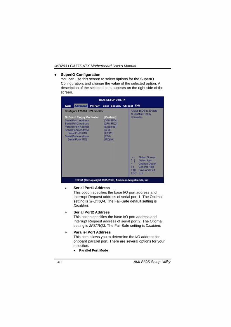
IMB203 LGA775 ATX Motherboard Userrsquos Manual
AMI BIOS Setup Utility 41
Select an operating mode for the onboard parallel (printer) port
Parallel Port IRQ Use this item to set up the IRQ for onboard parallel port
Serial Port3 Address This item specifies the base IO port address and Interrupt Request address of serial port 3 The Optimal setting is 3E8IRQ11 The Fail-Safe default setting is Disabled
Serial Port3 IRQ This item specifies the IRQ used by the serial port 3
Serial Port4 Address This item specifies the base IO port address and Interrupt Request address of serial port 4 The Optimal setting is 2E8IRQ10 The Fail-Safe default setting is Disabled
Serial Port4 IRQ This item specifies the IRQ used by the serial port 4
IMB203 LGA775 ATX Motherboard Userrsquos Manual
AMI BIOS Setup Utility 42
Hardware Health Configuration This screen shows the Hardware Health Configuration and a description of the selected item appears on the right side of the screen
HW Health Configuration
This screen displays the temperature of CPU and System Fan Speed Vcore etc
IMB203 LGA775 ATX Motherboard Userrsquos Manual
AMI BIOS Setup Utility 43
ACPI Configuration You can use this screen to select options for the ACPI Configuration and change the value of the selected option A description of the selected item appears on the right side of the screen
General ACPI Configuration
Scroll to this item and press ltEntergt to view the General ACPI Configuration sub menu which contains General ACPI (Advanced Configuration and Power Management Interface) options for your configuration
Advanced ACPI Configuration Scroll to this item and press ltEntergt to view the Advanced ACPI Configuration sub menu which contains Advanced ACPI (Advanced Configuration and Power Management Interface) options for your configuration
Chipset ACPI Configuration Scroll to this item and press ltEntergt to view the Chipset ACPI Configuration sub menu which contains Chipset ACPI (Advanced Configuration and Power Management
IMB203 LGA775 ATX Motherboard Userrsquos Manual
AMI BIOS Setup Utility 44
Interface) options for your configuration AHCI Configuration
You can use this screen to select options for the AHCI Configuration and change the value of the selected option A description of the selected item appears on the right side of the screen
AHCI BIOS Support You can enable or disable this item to control the AHCI function of the SATA controller
IMB203 LGA775 ATX Motherboard Userrsquos Manual
AMI BIOS Setup Utility 45
Intel iAMT Configuration You can use this screen to select options for the Intel iAMT Configuration and change the value of the selected option A description of the selected item appears on the right side of the screen
Intel iAMT Support
You can enable this item to support iAMT (active management technology) function to follow up the procedure for the access to AMI program screen
Unconfigure iAMTME Use this item to unconfigure the iAMTME settings
IMB203 LGA775 ATX Motherboard Userrsquos Manual
AMI BIOS Setup Utility 46
Intel VT-d Configuration You can use this screen to select options for the Intel VT-d Configuration and change the value of the selected option A description of the selected item appears on the right side of the screen
Intel VT-d Virtualization Technology for Directed IO (VT-d) extends Virtualization Technology (VT) roadmap by providing hardware assists for virtualization solution VT-d can help end users improve security and reliability of the systems and also improve performance of IO devices in virtualized environment Here are the options for your selection Disabled and Enabled
IMB203 LGA775 ATX Motherboard Userrsquos Manual
AMI BIOS Setup Utility 47
Remote Access Configuration You can use this screen to select options for the Remote Access Configuration and change the value of the selected option A description of the selected item appears on the right side of the screen
Remote Access Use this item to enable or disable the Remote Access function
IMB203 LGA775 ATX Motherboard Userrsquos Manual
AMI BIOS Setup Utility 48
PCI Express Configuration This screen shows the PCI Express Configuration and you can change its value A description of the selected item appears on the right side of the screen
Active State Power-Management
Use this item to enable or disable the function of Active State Power-Management to provide you with lower power consumption The default setting is Disabled
IMB203 LGA775 ATX Motherboard Userrsquos Manual
AMI BIOS Setup Utility 49
Trusted Computing You can use this screen to select options for the Trusted Computing and change the value of the selected option A description of the selected item appears on the right side of the screen
TCGTPM SUPPORT Use this item to control the Trusted Platform Module (TPM) function
IMB203 LGA775 ATX Motherboard Userrsquos Manual
AMI BIOS Setup Utility 50
USB Configuration You can use this screen to select options for the USB Configuration and change the value of the selected option A description of the selected item appears on the right side of the screen
USB Functions
This item allows you to enable or disable USB functions
Legacy USB Support Use this item to enable or disable support for USB device on legacy operating system The default setting is Enabled
USB 20 Controller Mode Use this item to configure the USB 20 controller The default setting is HiSpeed
BIOS EHCI Hand-Off Enabling this item provide the support for operating systems without an EHCI hand-off feature The default setting is Enabled
IMB203 LGA775 ATX Motherboard Userrsquos Manual
AMI BIOS Setup Utility 51
IMB203 LGA775 ATX Motherboard Userrsquos Manual
AMI BIOS Setup Utility 52
55 PCI PnP Menu The PCI PnP menu allows users to change the advanced settings for PCIPnP devices
Clear NVRAM
Use this item to clear the data in the NVRAM (CMOS) Here are the options for your selection No and Yes
Plug amp Play OS When the setting is No Use this item to configure all the devices in the system When the setting is Yes and if you install a Plug and Play operating system the operating system configures the Plug and Play devices not required for boot The default setting is No
IMB203 LGA775 ATX Motherboard Userrsquos Manual
AMI BIOS Setup Utility 53
PCI Latency Timer This item controls how long a PCI device can hold the PCI bus before another takes over The longer the latency the longer the PCI device can retain control of the bus before handing it over to another PCI device There are several options for your selection
Allocate IRQ to PCI VGA This item allows BIOS to choose an IRQ to assign for the PCI VGA card Here are the options for your selection No and Yes
Palette Snooping Some old graphic controllers need to ldquosnooprdquo on the VGA palette and then map it to their display as a way to provide boot information and VGA compatibility This item allows such snooping to take place Here are the options for your selection Disabled and Enabled
PCI IDE BusMaster This item is a toggle for the built-in driver that allows the onboard IDE controller to perform DMA (Direct Memory Access) transfer Here are the options for your selection Disabled and Enabled
OffBoard PCIISA IDE Card This item is for any other non-onboard PCIISA IDE controller adapter There are several options for your selection
IRQ3457910111415 These items will allow you to assign each system interrupt a type depending on the type of device using the interrupt The option ldquoAvailablerdquo means the IRQ is going to assign automatically Here are the options for your selection Available and Reserved
DMA Channel 013567 These items will allow you to assign each DMA channel a type depending on the type of device using the channel The option ldquoAvailablerdquo means the channel is going to assign automatically Here are the options for your selection Available and Reserved
IMB203 LGA775 ATX Motherboard Userrsquos Manual
AMI BIOS Setup Utility 54
56 Boot Menu The Boot menu allows users to change boot options of the system You can select any of the items in the left frame of the screen to go to the sub menus
Boot Settings Configuration Boot Device Priority Removable Drives
For items marked with ldquo rdquo please press ltEntergt for more options
IMB203 LGA775 ATX Motherboard Userrsquos Manual
AMI BIOS Setup Utility 55
Boot Settings Configuration
Quick Boot
Enabling this item lets the BIOS skip some power on self tests (POST) The default setting is Enabled
AddOn ROM Display Mode This item selects the display mode for option ROM The default setting is Force BIOS
Boot Num-Lock Use this item to select the power-on state for the NumLock The default setting is On
PS2 Mouse Support This item determines if the BIOS should reserve IRQ12 for the PS2 mouse or allow other devices to make use of this IRQ Here are the options for your selection Auto Enabled and Disabled
Wait For lsquoF1rsquo Of Error If this item is enabled the system waits for the F1 key to be pressed when error occurs The default setting is Enabled
Hit lsquoDELrsquo Message Display If this item is enabled the system displays the message
IMB203 LGA775 ATX Motherboard Userrsquos Manual
AMI BIOS Setup Utility 56
ldquoPress DEL to run Setuprdquo during POST The default setting is Enabled
Interrupt 19 Capture If this item is enabled this function makes the option ROMs to trap Interrupt 19 The default setting is Disabled
Boot Device Priority The Boot Device Priority screen specifies the boot device priority sequence from the available devices
IMB203 LGA775 ATX Motherboard Userrsquos Manual
AMI BIOS Setup Utility 57
Removable Drives Use this screen to view the removable drives in the system The BIOS will attempt to arrange the removable drive boot sequence automatically You can also change the booting sequence
IMB203 LGA775 ATX Motherboard Userrsquos Manual
AMI BIOS Setup Utility 58
57 Security Menu The Security menu allows users to change the security settings for the system
Supervisor Password
This item indicates whether a supervisor password has been set If the password has been installed Installed displays If not Not Installed displays
User Password This item indicates whether a user password has been set If the password has been installed Installed displays If not Not Installed displays
Change Supervisor Password Select this option and press ltEntergt to access the sub menu You can use the sub menu to change the supervisor password
Change User Password Select this option and press ltEntergt to access the sub menu You can use the sub menu to change the user password
IMB203 LGA775 ATX Motherboard Userrsquos Manual
AMI BIOS Setup Utility 59
58 Chipset Menu The Chipset menu allows users to change the advanced chipset settings You can select any of the items in the left frame of the screen to go to the sub menus
North Bridge Configuration South Bridge Configuration ME Subsystem Configuration
For items marked with ldquo rdquo please press ltEntergt for more options
IMB203 LGA775 ATX Motherboard Userrsquos Manual
AMI BIOS Setup Utility 60
North Bridge Configuration
Memory Remap Feature
Use this item to enable or disable the remapping of the overlapped PCI memory above the total physical memory Only 64-bit OS supports this function
DRAM Frequency This item allows you to control the Memory Clock
Configure DRAM Timing by SPD This item can enable or disable DRAM timing by SPD (Serial Presence Detect) device which is a small EEPROM chip on the memory module containing important information about the module speed size addressing mode and various parameters
Memory Hole You can reserve this area of system memory for ISA adapter ROM When this area is reserved it cannot be cached Check the user information of peripherals that need to use this area o f system memory for the memory requirements Here are the options Disabled and 15M-16M
IMB203 LGA775 ATX Motherboard Userrsquos Manual
AMI BIOS Setup Utility 61
Initiate Graphic Adapter When using multiple graphics cards this item can select which graphics controller to be the primary display device during boot
IGD Graphics Mode Select This item allows you to select the amount of system memory used by the internal graphics device
PEG Port ConfigurationPEG Port This item is a toggle to enable or disable the PCI Express port Here are the options for your selection Auto and Disabled
Video Function Configuration Press ltEntergt for the sub-menu for setting up video function
IMB203 LGA775 ATX Motherboard Userrsquos Manual
AMI BIOS Setup Utility 62
South Bridge Configuration
GbE Wake Up From S5 This item specifies whether the system will be awakened from the S5 power
HDA Controller This item allows you to enable or disable the HD audio support
Restore on AC Power Loss This item can control how the PC will behave once power is restored following a power outage or other unexpected shutdown
PCIE Port Configuration This item allows you to set or disable the PCI Express Ports
IMB203 LGA775 ATX Motherboard Userrsquos Manual
AMI BIOS Setup Utility 63
ME Subsystem Configuration
It is strongly recommended that you do not modify these options unless you are an advanced user
IMB203 LGA775 ATX Motherboard Userrsquos Manual
AMI BIOS Setup Utility 64
59 Exit Menu The Exit menu allows users to load your system configuration with optimal or failsafe default values
Save Changes and Exit
When you have completed the system configuration changes select this option to leave Setup and reboot the computer so the new system configuration parameters can take effect Select Save Changes and Exit from the Exit menu and press ltEntergt Select Ok to save changes and exit
Discard Changes and Exit Select this option to quit Setup without making any permanent changes to the system configuration Select Discard Changes and Exit from the Exit menu and press ltEntergt Select Ok to discard changes and exit
Load Optimal Defaults It automatically sets all Setup options to a complete set of default settings when you select this option The Optimal settings are designed for maximum system performance but may not work best for all computer applications In particular do not use the Optimal Setup options if your
IMB203 LGA775 ATX Motherboard Userrsquos Manual
AMI BIOS Setup Utility 65
computer is experiencing system configuration problems Select Load Optimal Defaults from the Exit menu and press ltEntergt
Load Fail-Safe Defaults It automatically sets all Setup options to a complete set of default settings when you select this option The Fail-Safe settings are designed for maximum system stability but not maximum performance Select the Fail-Safe Setup options if your computer is experiencing system configuration problems Select Load Fail-Safe Defaults from the Exit menu and press ltEntergt Select Ok to load Fail-Safe defaults
IMB203 LGA775 ATX Motherboard Userrsquos Manual
AMI BIOS Setup Utility 66
MEMO
IMB203 LGA775 ATX Motherboard Userrsquos Manual
Installation of Drivers 67
CHPATER 6 INSTALLATION OF DRIVERS
The device drivers are located on the Product Information CD-ROM that comes with the IMB203 Series package The auto-run function of drivers will guide you to install the utilities and device drivers under a Windows system You can follow the onscreen instructions to install these devices
Chipse VGA LAN Audio iAMT MEI
61 Installing Chipset Driver 1 Run the SETUPEXE program from the driver directory in
your driver CD Click ldquoNextrdquo to next step
IMB203 LGA775 ATX Motherboard Userrsquos Manual
Installation of Drivers 68
2 An Intelreg License Agreement appears to show you the important information Click ldquoYesrdquo to next step
3 Refer to the Readme file below to view the system requirements and installation information
IMB203 LGA775 ATX Motherboard Userrsquos Manual
Installation of Drivers 69
3-1 Please wait while running the following setup operations
3-2 Please wait while running the following setup operations
IMB203 LGA775 ATX Motherboard Userrsquos Manual
Installation of Drivers 70
4 Click ldquoFinishrdquo to complete the setup process
5 You will be asked to reboot your computer when the installation is completed Please click ldquoYes I want to restart my computer nowrdquo if you donrsquot need to install any other drivers Otherwise please click ldquoNo I will restart my computer laterrdquo and go on next step
IMB203 LGA775 ATX Motherboard Userrsquos Manual
Installation of Drivers 71
62 Installing VGA Driver 1 Run the SETUPEXE program from the driver directory in
your driver CD Click ldquoNextrdquo to next step
2 An Intelreg License Agreement appears to show you the
important information Click ldquoYesrdquo to next step
IMB203 LGA775 ATX Motherboard Userrsquos Manual
Installation of Drivers 72
3 The message of Readme File Information appears to show you the system requirements and installation information Please click ldquoNextrdquo
4 Please wait while running the following setup operations
When this message appears please click ldquoNextrdquo
IMB203 LGA775 ATX Motherboard Userrsquos Manual
Installation of Drivers 73
5 Click ldquoFinishrdquo to complete the setup process
6 You will be asked to reboot your computer when the installation is completed Please click ldquoYes I want to restart my computer nowrdquo if you donrsquot need to install any other drivers Otherwise please click ldquoNo I will restart my computer laterrdquo and click ldquoFinishrdquo to complete the installation
IMB203 LGA775 ATX Motherboard Userrsquos Manual
Installation of Drivers 74
63 Installing LAN Driver
11 Run the InstallShield Wizard for Network Connections from
the driver directory in your driver CD Click ldquoNextrdquo to next step
IMB203 LGA775 ATX Motherboard Userrsquos Manual
Installation of Drivers 75
12 An Intelreg License Agreement appears to show you the important information Click ldquoYesrdquo to next step
13 A Setup Options window appears that you can select the
program features you want to install
IMB203 LGA775 ATX Motherboard Userrsquos Manual
Installation of Drivers 76
2 Click ldquoInstallrdquo to start the installation
3 Please wait while running the following installation operation
IMB203 LGA775 ATX Motherboard Userrsquos Manual
Installation of Drivers 77
4 Click ldquoFinishrdquo to complete the installation
Note The Driver item [Wake on Directed Packet] default is Enabled under Windows Vista
格式化 字型 (符號) Arial
格式化 字型 (符號) Arial
格式化 字型 斜體 字型色彩 黑色 (符號) Arial 非加寬 緊縮
格式化 字型 斜體 字型色彩 黑色 (符號) Arial 非加寬 緊縮
格式化 字型 (符號) Arial 非加寬 緊縮
IMB203 LGA775 ATX Motherboard Userrsquos Manual
Installation of Drivers 78
64 Installing AUDIO Driver 1 Run the InstallShield Wizard for Realtek High Definition
Audio Driver from the driver directory in your driver CD Click ldquoNextrdquo to next step
IMB203 LGA775 ATX Motherboard Userrsquos Manual
Installation of Drivers 79
2 Click ldquoInstallrdquo to start the installation and wait while running the installation operation
3 Click ldquoFinishrdquo to complete the installation
IMB203 LGA775 ATX Motherboard Userrsquos Manual
Installation of Drivers 80
65 Installing iAMT (Active Management Technology) Driver
Note You must download and properly install the required NET version 35 provided from a separate downloading of the actual FimwareTools kit releases posted on VIP prior to loading the MEILMS Driver stack
651 LMS_SOL Setup
1 Run the setup program to install Intelreg Active Management Technology onto your computer It is strongly recommended that you exit all programs before continuing Click ldquoNextrdquo to next step
格式化 字型 (符號) Arial
格式化 字型 (符號) Arial 非加寬 緊縮
IMB203 LGA775 ATX Motherboard Userrsquos Manual
Installation of Drivers 81
2 An Intelreg license agreement appears that you need to continue the setup program by clicking ldquoYesrdquo to accept the terms
IMB203 LGA775 ATX Motherboard Userrsquos Manual
Installation of Drivers 82
3 Refer to the Readme file below to view the system requirements and installation information Click ldquoNextrdquo to next setup
4 Please wait while running the following installation operation
IMB203 LGA775 ATX Motherboard Userrsquos Manual
Installation of Drivers 83
5 Click ldquoFinishrdquo to complete the installation
IMB203 LGA775 ATX Motherboard Userrsquos Manual
Installation of Drivers 84
652 LMS_SOL_IS Setup
1 Run the setup program to install Intelreg Active Management Technology onto your computer It is strongly recommended that you exit all programs before continuing Click ldquoNextrdquo to next step
IMB203 LGA775 ATX Motherboard Userrsquos Manual
Installation of Drivers 85
2 An Intelreg license agreement appears that you need to continue the setup program by clicking ldquoYesrdquo to accept the terms
IMB203 LGA775 ATX Motherboard Userrsquos Manual
Installation of Drivers 86
3 Refer to the Readme file below to view the system requirements and installation information Click ldquoNextrdquo to next setup
4 Please wait while running the following installation operation
IMB203 LGA775 ATX Motherboard Userrsquos Manual
Installation of Drivers 87
5 Click ldquoFinishrdquo to complete the installation
IMB203 LGA775 ATX Motherboard Userrsquos Manual
Installation of Drivers 88
66 Installing MEI (Management Engine Interface) Driver
Note You must download and properly install the required NET version 35 provided from a separate downloading of the actual FimwareTools kit releases posted on VIP prior to loading the MEILMS Driver stack
1 Run the setup program to install Intelreg Management Engine
Interface onto your computer It is strongly recommended that you exit all programs before continuing Click ldquoNextrdquo to next step
格式化 字型 (符號) Arial
格式化 字型 (符號) Arial 非加寬 緊縮
IMB203 LGA775 ATX Motherboard Userrsquos Manual
Installation of Drivers 89
2 An Intelreg license agreement appears that you need to continue the setup program by clicking ldquoYesrdquo to accept the terms
IMB203 LGA775 ATX Motherboard Userrsquos Manual
Installation of Drivers 90
3 Refer to the Readme file below to view the system requirements and installation information Click ldquoNextrdquo to next setup
4 Please wait while running the following installation operation
IMB203 LGA775 ATX Motherboard Userrsquos Manual
Installation of Drivers 91
5 Click ldquoFinishrdquo to complete the installation
IMB203 LGA775 ATX Motherboard Userrsquos Manual
Installation of Drivers 92
MEMO
IMB203 LGA775 ATX Motherboard Userrsquos Manual
Watchdog Timer 93
APPENDIX A WATCHDOG TIMER
Watchdog Timer Setting After the system stops working for a while it can be auto-reset by the Watchdog Timer The integrated Watchdog Timer can be set up in the system reset mode by program
Using the Watchdog Function Start darr Un-Lock WDT O 2E 87 Un-lock super IO
O 2E 87 Un-lock super IO darr Set WDT Function O 2E 2D O 2F 20 Select Logic device O 2E 07 O 2F 08 darr Activate WDT O 2E 30
O 2F 01 Set Second or Minute O 2E F5
O 2F N N=00 or 08(See below table) darr Set base timer O 2E F6
O 2F M=000102hellipFF(Hex) Value=0 to 255 darr WDT counting
re-set timer O 2E F6
O 2F M M=000102hellipFF(See below table) darr
格式化
格式化 項目符號及編號
格式化 項目符號及編號
格式化 字型 8 點 字型色彩黑色
格式化 字型 8 點 字型色彩黑色
格式化 定位點 1257 字元左 + 不在 1012 字元 + 1386字元
格式化 字型 8 點 字型色彩黑色
格式化 定位點 1257 字元左 + 不在 134 字元 + 1362字元
格式化 字型色彩 黑色
格式化 字型色彩 黑色
刪除
IMB203 LGA775 ATX Motherboard Userrsquos Manual
Watchdog Timer 94
IF No re-set timer WDT time-out generate RESET IF to disable WDT O 2E 30
O 2F 00 Can be disable at any time
N=00
M= 00h Time-out Disable 01h Time-out occurs after 1 second 02h Time-out occurs after 2 second 03h Time-out occurs after 3 second helliphelliphelliphelliphelliphelliphelliphelliphellip FFh Time-out occurs after 255 second
N=08
M= 00h Time-out Disable 01h Time-out occurs after 1 minute 02h Time-out occurs after 2 minutes 03h Time-out occurs after 3 minutes helliphelliphelliphelliphelliphelliphelliphelliphellip
FFh Time-out occurs after 255 minutes
格式化 字型色彩 黑色
格式化 字型色彩 黑色
IMB203 LGA775 ATX Motherboard Userrsquos Manual
PCI IRQ Routing 95
APPENDIX B PCI IRQ ROUTING
PICMG PCI IRQ Routing
Device ID Slot Int
PCI Slot 0 31 0 BCDA PCI Slot 1 30 1 CDAB PCI Slot 2 29 2 DABC PCI Slot 3 28 3 ABCD
IMB203 LGA775 ATX Motherboard Userrsquos Manual
PCI IRQ Routing 96
MEMO
IMB203 LGA775 ATX Motherboard Userrsquos Manual
Configuring SATA for RAID Function 97
APPENDIX C CONFIGURING SATA FOR RAID
FUNCTION
Configuring SATA Hard Drive(s) for RAID Function (Controller IntelregICH10DODO DH only) Please follow up the steps below to configure SATA hard drive(s) (1) Install SATA hard drive(s) in your system (2) Enter the BIOS Setup to configure SATA controller mode and boot
sequence (3) Configure RAID by the RAID BIOS (4) Install the SATA controller driver during the OS installation Before you begin the SATA configuration please prepare (a) Two SATA hard drives (to ensure optimal performance it is
recommended that you use two hard drives with identical model and capacity) If you do not want to create RAID with the SATA controller you may prepare only one hard drive
(b) An empty formatted floppy disk (c) Windows XP setup disk (1) Installing SATA hard drive(s) in your system
Connect one end of the SATA signal cable to the rear of the SATA hard drive and the other end to available SATA port(s) on the board Then connect the power connector of power supply to the hard drive
(2) Configuring SATA controller mode and boot sequence by the BIOS Setup You have to make sure whether the SATA controller is configured correctly by system BIOS Setup and set up BIOS boot sequence for the SATA hard drive(s)
IMB203 LGA775 ATX Motherboard Userrsquos Manual
Configuring SATA for RAID Function 98
(2)-1-1 Turn on your system and then press the Del button to enter BIOS Setup during running POST (Power-On Self Test) If you want to create RAID just go to the Advanced Settings menuIDE configuration select the Configure SATA1 as and press ltEntergt for more options
IMB203 LGA775 ATX Motherboard Userrsquos Manual
Configuring SATA for RAID Function 99
(2)-1-2 A list of options appears please select RAID
IMB203 LGA775 ATX Motherboard Userrsquos Manual
Configuring SATA for RAID Function 100
(2)-2 Set CDROM for First Boot Device under the Boot Settings menu to boot CD-ROM after system restarts
(2)-3 Save and exit the BIOS Setup
IMB203 LGA775 ATX Motherboard Userrsquos Manual
Configuring SATA for RAID Function 101
(3) Configuring RAID by the RAID BIOS Enter the RAID BIOS setup utility to configure a RAID array Skip this step and proceed to Section 4 if you do not want to create a RAID (3)-1 After the POST memory testing and before the operating
system booting a message Press ltCtrl-Igt to enter Configuration Utility shows up accordingly press ltCTRL+ Igt to enter the RAID BIOS setup utility
(3)-2 After you press ltCTRL+ Igt the Create RAID Volume screen will appear If you want to create a RAID array select the Create RAID Volume option in the Main Menu and press ENTER
IMB203 LGA775 ATX Motherboard Userrsquos Manual
Configuring SATA for RAID Function 102
(3)-3-1 After entering the CREATE VOLUME MENU screen you can type the disk array name with 1~16 letters (letters cannot be special characters) in the item ldquoNamerdquo
(3)-3-2 When finished press ENTER to select a RAID level There are three RAID levels RAID0 RAID1 and RAID5 amp RAID10 Select a RAID level and press ENTER
IMB203 LGA775 ATX Motherboard Userrsquos Manual
Configuring SATA for RAID Function 103
(3)-4 Set the stripe block size The KB is the standard unit of stripe block size The stripe block size can be 4KB to 128KB After the setting press ENTER for the array capacity
(3)-5 After setting all the items on the menu select Create Volume
and press ENTER to start creating the RAID array
IMB203 LGA775 ATX Motherboard Userrsquos Manual
Configuring SATA for RAID Function 104
(3)-6 When prompting the confirmation press ldquoYldquo to create this volume or ldquoNldquo to cancel the creation
After the creation is completed you can see detailed information about the RAID Array in the DISKVOLUME INFORMATION section including RAID mode disk block size disk name and disk capacity etc
IMB203 LGA775 ATX Motherboard Userrsquos Manual
Configuring SATA for RAID Function 105
Delete RAID Volume If you want to delete a RAID volume select the Delete RAID Volume option in Main Menu Press ENTER and follow on-screen instructions
Please press [ESC] to exit the RAID BIOS utility Now you can proceed to install a SATA driver controller and the operating system
IMB203 LGA775 ATX Motherboard Userrsquos Manual
Configuring SATA for RAID Function 106
(4) Making a SATA Driver Disk To install the operating system onto a serial ATA hard disk successfully you need to install the SATA controller driver during the OS installation Without the driver the hard disk may not be recognized during the Windows setup process First of all please format a blank floppy disk Secondly follow up these steps below to produce a SATA driver disk Users can insert the Driver CD and the formatted blank floppy disk in another system And then please copy all of file of the f6flpy32 folder in the Driver CD to a floppy disk Note Please copy all of file of the f6flpy64 folder if installing 64-bit
Windows Operating System
IMB203 LGA775 ATX Motherboard Userrsquos Manual
Configuring SATA for RAID Function 107
(5) Installing the SATA controller driver during the OS installation Now the SATA driver disk is ready and BIOS settings configured you can proceed to install Windows 2000XP onto your SATA hard drive using the SATA driver Here is an example for Windows XP installation (5)-1 Restart your system to boot the Windows 2000XP Setup disk
and press F6 button as soon as you see the message Press F6 if you need to install a 3rd party SCSI or RAID driver After pressing the F6 button there will be a few moments for some files being loaded before next screen appears
IMB203 LGA775 ATX Motherboard Userrsquos Manual
Configuring SATA for RAID Function 108
(5)-2 When you see the screen below insert the floppy disk containing the SATA driver and press ldquoSrdquo
(5)-3 If the Setup correctly recognizes the driver of the floppy disk
a controller menu will appear below Use the ARROW keys to select Intel(R) ICH8RICH9RICH10RDO SATA RAID Controller and press ENTER Then it will begin to load the SATA driver from the floppy disk
IMB203 LGA775 ATX Motherboard Userrsquos Manual
Configuring SATA for RAID Function 109
Note If a message on the screen saying that one or some file(s) cannot be found please check the floppy disk or copy the correct SATA driver again from the driver CD
IMB203 LGA775 ATX Motherboard Userrsquos Manual
Configuring SATA for RAID Function 110
MEMO
IMB203 LGA775 ATX Motherboard Userrsquos Manual
iAMT Settings 111
APPENDIX D iAMT SETTINGS
The Intelreg Active Management Technology (Intelreg iAMT) has decreased a major barrier to IT efficiency that uses built-in platform capabilities and popular third-party management and security applications to allow IT a better discovering healing and protection their networked computing assets In order to utilize Intel iAMT you must enter the ME BIOS (CTRL + P during system startup) change the ME BIOS password and then select ldquoIntelreg iAMTrdquo as the manageability feature
D1 Entering MEBx 1 You must go to BIOS TO start iAMT function 2 Exit from BIOS after starting iAMT and press Ctrl+P to enter MEBx Setting
It is better to press Ctrl+P before the screen popping out
格式化
IMB203 LGA775 ATX Motherboard Userrsquos Manual
iAMT Settings 112
D2 Set amp Change Password 1 You will be asked to set a password when first log in The default
password is lsquoadminrsquo
2 You will be asked to change the password before setting ME
Change Password
IMB203 LGA775 ATX Motherboard Userrsquos Manual
iAMT Settings 113
3 You must confirm your new password while revising (as Remark 1)
Remark 1 The new password must contain (example 11qqQQ) (default value)
Eight characters
One upper case
One lower case
One number
One special symbol such as $ or
( excepted)
Underline ( _ ) and space are valid characters for password but they wonrsquot make higher complexity
IMB203 LGA775 ATX Motherboard Userrsquos Manual
iAMT Settings 114
D3 Intelreg iAMT Settings 1 Select Intelreg iAMT Configuration and press ltENTERgt
2 Key in the Host Name If Intelreg iAMT set to lsquoDHCPlsquo the Host name must be identical to the operating system mechanic
IMB203 LGA775 ATX Motherboard Userrsquos Manual
iAMT Settings 115
3 Select TCPIP to get into Network interface and set it to lsquoENABLEDrsquo into DHCP Mode and set it to lsquoDISABLEDrsquo (as Remark 2) into Domain name and set the Intel Management Engine domain name such as lsquoAMTintelcomrsquo
(3-1)
(3-2)
IMB203 LGA775 ATX Motherboard Userrsquos Manual
iAMT Settings 116
Remark 2 DHCP Mode lsquoDISABLEDlsquo if DHCP Mode is disabled you can make the following settings
IP address
Subnet mask
IMB203 LGA775 ATX Motherboard Userrsquos Manual
iAMT Settings 117
Default Gateway address
Preferred DNS address
IMB203 LGA775 ATX Motherboard Userrsquos Manual
iAMT Settings 118
Alternate DNS address
Domain name
4 Exit from MEBx after completing the iAMT settings
IMB203 LGA775 ATX Motherboard Userrsquos Manual
iAMT Settings 119
D4 iAMT Web Console 1 From a web browser please type http(IP ADDRESS)16992
which connects to iAMT Web Example http1014021416992
2 To log on you will be required to type in username and password
for access to the Web
USER admin (default value)
PASS (MEBx password)
IMB203 LGA775 ATX Motherboard Userrsquos Manual
iAMT Settings 120
3 Enter the iAMT Web
4 Click Remote Control and select commands on the right side
IMB203 LGA775 ATX Motherboard Userrsquos Manual
iAMT Settings 121
5 When you have finished using the iAMT Web console close the Web browser
IMB203 LGA775 ATX Motherboard Userrsquos Manual
iAMT Settings 122
MEMO
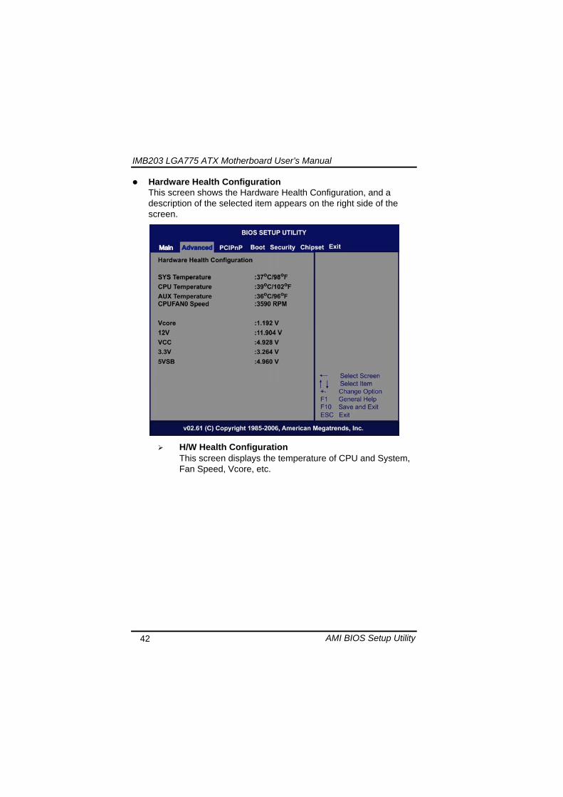
IMB203 LGA775 ATX Motherboard Userrsquos Manual
AMI BIOS Setup Utility 43
ACPI Configuration You can use this screen to select options for the ACPI Configuration and change the value of the selected option A description of the selected item appears on the right side of the screen
General ACPI Configuration
Scroll to this item and press ltEntergt to view the General ACPI Configuration sub menu which contains General ACPI (Advanced Configuration and Power Management Interface) options for your configuration
Advanced ACPI Configuration Scroll to this item and press ltEntergt to view the Advanced ACPI Configuration sub menu which contains Advanced ACPI (Advanced Configuration and Power Management Interface) options for your configuration
Chipset ACPI Configuration Scroll to this item and press ltEntergt to view the Chipset ACPI Configuration sub menu which contains Chipset ACPI (Advanced Configuration and Power Management
IMB203 LGA775 ATX Motherboard Userrsquos Manual
AMI BIOS Setup Utility 44
Interface) options for your configuration AHCI Configuration
You can use this screen to select options for the AHCI Configuration and change the value of the selected option A description of the selected item appears on the right side of the screen
AHCI BIOS Support You can enable or disable this item to control the AHCI function of the SATA controller
IMB203 LGA775 ATX Motherboard Userrsquos Manual
AMI BIOS Setup Utility 45
Intel iAMT Configuration You can use this screen to select options for the Intel iAMT Configuration and change the value of the selected option A description of the selected item appears on the right side of the screen
Intel iAMT Support
You can enable this item to support iAMT (active management technology) function to follow up the procedure for the access to AMI program screen
Unconfigure iAMTME Use this item to unconfigure the iAMTME settings
IMB203 LGA775 ATX Motherboard Userrsquos Manual
AMI BIOS Setup Utility 46
Intel VT-d Configuration You can use this screen to select options for the Intel VT-d Configuration and change the value of the selected option A description of the selected item appears on the right side of the screen
Intel VT-d Virtualization Technology for Directed IO (VT-d) extends Virtualization Technology (VT) roadmap by providing hardware assists for virtualization solution VT-d can help end users improve security and reliability of the systems and also improve performance of IO devices in virtualized environment Here are the options for your selection Disabled and Enabled
IMB203 LGA775 ATX Motherboard Userrsquos Manual
AMI BIOS Setup Utility 47
Remote Access Configuration You can use this screen to select options for the Remote Access Configuration and change the value of the selected option A description of the selected item appears on the right side of the screen
Remote Access Use this item to enable or disable the Remote Access function
IMB203 LGA775 ATX Motherboard Userrsquos Manual
AMI BIOS Setup Utility 48
PCI Express Configuration This screen shows the PCI Express Configuration and you can change its value A description of the selected item appears on the right side of the screen
Active State Power-Management
Use this item to enable or disable the function of Active State Power-Management to provide you with lower power consumption The default setting is Disabled
IMB203 LGA775 ATX Motherboard Userrsquos Manual
AMI BIOS Setup Utility 49
Trusted Computing You can use this screen to select options for the Trusted Computing and change the value of the selected option A description of the selected item appears on the right side of the screen
TCGTPM SUPPORT Use this item to control the Trusted Platform Module (TPM) function
IMB203 LGA775 ATX Motherboard Userrsquos Manual
AMI BIOS Setup Utility 50
USB Configuration You can use this screen to select options for the USB Configuration and change the value of the selected option A description of the selected item appears on the right side of the screen
USB Functions
This item allows you to enable or disable USB functions
Legacy USB Support Use this item to enable or disable support for USB device on legacy operating system The default setting is Enabled
USB 20 Controller Mode Use this item to configure the USB 20 controller The default setting is HiSpeed
BIOS EHCI Hand-Off Enabling this item provide the support for operating systems without an EHCI hand-off feature The default setting is Enabled
IMB203 LGA775 ATX Motherboard Userrsquos Manual
AMI BIOS Setup Utility 51
IMB203 LGA775 ATX Motherboard Userrsquos Manual
AMI BIOS Setup Utility 52
55 PCI PnP Menu The PCI PnP menu allows users to change the advanced settings for PCIPnP devices
Clear NVRAM
Use this item to clear the data in the NVRAM (CMOS) Here are the options for your selection No and Yes
Plug amp Play OS When the setting is No Use this item to configure all the devices in the system When the setting is Yes and if you install a Plug and Play operating system the operating system configures the Plug and Play devices not required for boot The default setting is No
IMB203 LGA775 ATX Motherboard Userrsquos Manual
AMI BIOS Setup Utility 53
PCI Latency Timer This item controls how long a PCI device can hold the PCI bus before another takes over The longer the latency the longer the PCI device can retain control of the bus before handing it over to another PCI device There are several options for your selection
Allocate IRQ to PCI VGA This item allows BIOS to choose an IRQ to assign for the PCI VGA card Here are the options for your selection No and Yes
Palette Snooping Some old graphic controllers need to ldquosnooprdquo on the VGA palette and then map it to their display as a way to provide boot information and VGA compatibility This item allows such snooping to take place Here are the options for your selection Disabled and Enabled
PCI IDE BusMaster This item is a toggle for the built-in driver that allows the onboard IDE controller to perform DMA (Direct Memory Access) transfer Here are the options for your selection Disabled and Enabled
OffBoard PCIISA IDE Card This item is for any other non-onboard PCIISA IDE controller adapter There are several options for your selection
IRQ3457910111415 These items will allow you to assign each system interrupt a type depending on the type of device using the interrupt The option ldquoAvailablerdquo means the IRQ is going to assign automatically Here are the options for your selection Available and Reserved
DMA Channel 013567 These items will allow you to assign each DMA channel a type depending on the type of device using the channel The option ldquoAvailablerdquo means the channel is going to assign automatically Here are the options for your selection Available and Reserved
IMB203 LGA775 ATX Motherboard Userrsquos Manual
AMI BIOS Setup Utility 54
56 Boot Menu The Boot menu allows users to change boot options of the system You can select any of the items in the left frame of the screen to go to the sub menus
Boot Settings Configuration Boot Device Priority Removable Drives
For items marked with ldquo rdquo please press ltEntergt for more options
IMB203 LGA775 ATX Motherboard Userrsquos Manual
AMI BIOS Setup Utility 55
Boot Settings Configuration
Quick Boot
Enabling this item lets the BIOS skip some power on self tests (POST) The default setting is Enabled
AddOn ROM Display Mode This item selects the display mode for option ROM The default setting is Force BIOS
Boot Num-Lock Use this item to select the power-on state for the NumLock The default setting is On
PS2 Mouse Support This item determines if the BIOS should reserve IRQ12 for the PS2 mouse or allow other devices to make use of this IRQ Here are the options for your selection Auto Enabled and Disabled
Wait For lsquoF1rsquo Of Error If this item is enabled the system waits for the F1 key to be pressed when error occurs The default setting is Enabled
Hit lsquoDELrsquo Message Display If this item is enabled the system displays the message
IMB203 LGA775 ATX Motherboard Userrsquos Manual
AMI BIOS Setup Utility 56
ldquoPress DEL to run Setuprdquo during POST The default setting is Enabled
Interrupt 19 Capture If this item is enabled this function makes the option ROMs to trap Interrupt 19 The default setting is Disabled
Boot Device Priority The Boot Device Priority screen specifies the boot device priority sequence from the available devices
IMB203 LGA775 ATX Motherboard Userrsquos Manual
AMI BIOS Setup Utility 57
Removable Drives Use this screen to view the removable drives in the system The BIOS will attempt to arrange the removable drive boot sequence automatically You can also change the booting sequence
IMB203 LGA775 ATX Motherboard Userrsquos Manual
AMI BIOS Setup Utility 58
57 Security Menu The Security menu allows users to change the security settings for the system
Supervisor Password
This item indicates whether a supervisor password has been set If the password has been installed Installed displays If not Not Installed displays
User Password This item indicates whether a user password has been set If the password has been installed Installed displays If not Not Installed displays
Change Supervisor Password Select this option and press ltEntergt to access the sub menu You can use the sub menu to change the supervisor password
Change User Password Select this option and press ltEntergt to access the sub menu You can use the sub menu to change the user password
IMB203 LGA775 ATX Motherboard Userrsquos Manual
AMI BIOS Setup Utility 59
58 Chipset Menu The Chipset menu allows users to change the advanced chipset settings You can select any of the items in the left frame of the screen to go to the sub menus
North Bridge Configuration South Bridge Configuration ME Subsystem Configuration
For items marked with ldquo rdquo please press ltEntergt for more options
IMB203 LGA775 ATX Motherboard Userrsquos Manual
AMI BIOS Setup Utility 60
North Bridge Configuration
Memory Remap Feature
Use this item to enable or disable the remapping of the overlapped PCI memory above the total physical memory Only 64-bit OS supports this function
DRAM Frequency This item allows you to control the Memory Clock
Configure DRAM Timing by SPD This item can enable or disable DRAM timing by SPD (Serial Presence Detect) device which is a small EEPROM chip on the memory module containing important information about the module speed size addressing mode and various parameters
Memory Hole You can reserve this area of system memory for ISA adapter ROM When this area is reserved it cannot be cached Check the user information of peripherals that need to use this area o f system memory for the memory requirements Here are the options Disabled and 15M-16M
IMB203 LGA775 ATX Motherboard Userrsquos Manual
AMI BIOS Setup Utility 61
Initiate Graphic Adapter When using multiple graphics cards this item can select which graphics controller to be the primary display device during boot
IGD Graphics Mode Select This item allows you to select the amount of system memory used by the internal graphics device
PEG Port ConfigurationPEG Port This item is a toggle to enable or disable the PCI Express port Here are the options for your selection Auto and Disabled
Video Function Configuration Press ltEntergt for the sub-menu for setting up video function
IMB203 LGA775 ATX Motherboard Userrsquos Manual
AMI BIOS Setup Utility 62
South Bridge Configuration
GbE Wake Up From S5 This item specifies whether the system will be awakened from the S5 power
HDA Controller This item allows you to enable or disable the HD audio support
Restore on AC Power Loss This item can control how the PC will behave once power is restored following a power outage or other unexpected shutdown
PCIE Port Configuration This item allows you to set or disable the PCI Express Ports
IMB203 LGA775 ATX Motherboard Userrsquos Manual
AMI BIOS Setup Utility 63
ME Subsystem Configuration
It is strongly recommended that you do not modify these options unless you are an advanced user
IMB203 LGA775 ATX Motherboard Userrsquos Manual
AMI BIOS Setup Utility 64
59 Exit Menu The Exit menu allows users to load your system configuration with optimal or failsafe default values
Save Changes and Exit
When you have completed the system configuration changes select this option to leave Setup and reboot the computer so the new system configuration parameters can take effect Select Save Changes and Exit from the Exit menu and press ltEntergt Select Ok to save changes and exit
Discard Changes and Exit Select this option to quit Setup without making any permanent changes to the system configuration Select Discard Changes and Exit from the Exit menu and press ltEntergt Select Ok to discard changes and exit
Load Optimal Defaults It automatically sets all Setup options to a complete set of default settings when you select this option The Optimal settings are designed for maximum system performance but may not work best for all computer applications In particular do not use the Optimal Setup options if your
IMB203 LGA775 ATX Motherboard Userrsquos Manual
AMI BIOS Setup Utility 65
computer is experiencing system configuration problems Select Load Optimal Defaults from the Exit menu and press ltEntergt
Load Fail-Safe Defaults It automatically sets all Setup options to a complete set of default settings when you select this option The Fail-Safe settings are designed for maximum system stability but not maximum performance Select the Fail-Safe Setup options if your computer is experiencing system configuration problems Select Load Fail-Safe Defaults from the Exit menu and press ltEntergt Select Ok to load Fail-Safe defaults
IMB203 LGA775 ATX Motherboard Userrsquos Manual
AMI BIOS Setup Utility 66
MEMO
IMB203 LGA775 ATX Motherboard Userrsquos Manual
Installation of Drivers 67
CHPATER 6 INSTALLATION OF DRIVERS
The device drivers are located on the Product Information CD-ROM that comes with the IMB203 Series package The auto-run function of drivers will guide you to install the utilities and device drivers under a Windows system You can follow the onscreen instructions to install these devices
Chipse VGA LAN Audio iAMT MEI
61 Installing Chipset Driver 1 Run the SETUPEXE program from the driver directory in
your driver CD Click ldquoNextrdquo to next step
IMB203 LGA775 ATX Motherboard Userrsquos Manual
Installation of Drivers 68
2 An Intelreg License Agreement appears to show you the important information Click ldquoYesrdquo to next step
3 Refer to the Readme file below to view the system requirements and installation information
IMB203 LGA775 ATX Motherboard Userrsquos Manual
Installation of Drivers 69
3-1 Please wait while running the following setup operations
3-2 Please wait while running the following setup operations
IMB203 LGA775 ATX Motherboard Userrsquos Manual
Installation of Drivers 70
4 Click ldquoFinishrdquo to complete the setup process
5 You will be asked to reboot your computer when the installation is completed Please click ldquoYes I want to restart my computer nowrdquo if you donrsquot need to install any other drivers Otherwise please click ldquoNo I will restart my computer laterrdquo and go on next step
IMB203 LGA775 ATX Motherboard Userrsquos Manual
Installation of Drivers 71
62 Installing VGA Driver 1 Run the SETUPEXE program from the driver directory in
your driver CD Click ldquoNextrdquo to next step
2 An Intelreg License Agreement appears to show you the
important information Click ldquoYesrdquo to next step
IMB203 LGA775 ATX Motherboard Userrsquos Manual
Installation of Drivers 72
3 The message of Readme File Information appears to show you the system requirements and installation information Please click ldquoNextrdquo
4 Please wait while running the following setup operations
When this message appears please click ldquoNextrdquo
IMB203 LGA775 ATX Motherboard Userrsquos Manual
Installation of Drivers 73
5 Click ldquoFinishrdquo to complete the setup process
6 You will be asked to reboot your computer when the installation is completed Please click ldquoYes I want to restart my computer nowrdquo if you donrsquot need to install any other drivers Otherwise please click ldquoNo I will restart my computer laterrdquo and click ldquoFinishrdquo to complete the installation
IMB203 LGA775 ATX Motherboard Userrsquos Manual
Installation of Drivers 74
63 Installing LAN Driver
11 Run the InstallShield Wizard for Network Connections from
the driver directory in your driver CD Click ldquoNextrdquo to next step
IMB203 LGA775 ATX Motherboard Userrsquos Manual
Installation of Drivers 75
12 An Intelreg License Agreement appears to show you the important information Click ldquoYesrdquo to next step
13 A Setup Options window appears that you can select the
program features you want to install
IMB203 LGA775 ATX Motherboard Userrsquos Manual
Installation of Drivers 76
2 Click ldquoInstallrdquo to start the installation
3 Please wait while running the following installation operation
IMB203 LGA775 ATX Motherboard Userrsquos Manual
Installation of Drivers 77
4 Click ldquoFinishrdquo to complete the installation
Note The Driver item [Wake on Directed Packet] default is Enabled under Windows Vista
格式化 字型 (符號) Arial
格式化 字型 (符號) Arial
格式化 字型 斜體 字型色彩 黑色 (符號) Arial 非加寬 緊縮
格式化 字型 斜體 字型色彩 黑色 (符號) Arial 非加寬 緊縮
格式化 字型 (符號) Arial 非加寬 緊縮
IMB203 LGA775 ATX Motherboard Userrsquos Manual
Installation of Drivers 78
64 Installing AUDIO Driver 1 Run the InstallShield Wizard for Realtek High Definition
Audio Driver from the driver directory in your driver CD Click ldquoNextrdquo to next step
IMB203 LGA775 ATX Motherboard Userrsquos Manual
Installation of Drivers 79
2 Click ldquoInstallrdquo to start the installation and wait while running the installation operation
3 Click ldquoFinishrdquo to complete the installation
IMB203 LGA775 ATX Motherboard Userrsquos Manual
Installation of Drivers 80
65 Installing iAMT (Active Management Technology) Driver
Note You must download and properly install the required NET version 35 provided from a separate downloading of the actual FimwareTools kit releases posted on VIP prior to loading the MEILMS Driver stack
651 LMS_SOL Setup
1 Run the setup program to install Intelreg Active Management Technology onto your computer It is strongly recommended that you exit all programs before continuing Click ldquoNextrdquo to next step
格式化 字型 (符號) Arial
格式化 字型 (符號) Arial 非加寬 緊縮
IMB203 LGA775 ATX Motherboard Userrsquos Manual
Installation of Drivers 81
2 An Intelreg license agreement appears that you need to continue the setup program by clicking ldquoYesrdquo to accept the terms
IMB203 LGA775 ATX Motherboard Userrsquos Manual
Installation of Drivers 82
3 Refer to the Readme file below to view the system requirements and installation information Click ldquoNextrdquo to next setup
4 Please wait while running the following installation operation
IMB203 LGA775 ATX Motherboard Userrsquos Manual
Installation of Drivers 83
5 Click ldquoFinishrdquo to complete the installation
IMB203 LGA775 ATX Motherboard Userrsquos Manual
Installation of Drivers 84
652 LMS_SOL_IS Setup
1 Run the setup program to install Intelreg Active Management Technology onto your computer It is strongly recommended that you exit all programs before continuing Click ldquoNextrdquo to next step
IMB203 LGA775 ATX Motherboard Userrsquos Manual
Installation of Drivers 85
2 An Intelreg license agreement appears that you need to continue the setup program by clicking ldquoYesrdquo to accept the terms
IMB203 LGA775 ATX Motherboard Userrsquos Manual
Installation of Drivers 86
3 Refer to the Readme file below to view the system requirements and installation information Click ldquoNextrdquo to next setup
4 Please wait while running the following installation operation
IMB203 LGA775 ATX Motherboard Userrsquos Manual
Installation of Drivers 87
5 Click ldquoFinishrdquo to complete the installation
IMB203 LGA775 ATX Motherboard Userrsquos Manual
Installation of Drivers 88
66 Installing MEI (Management Engine Interface) Driver
Note You must download and properly install the required NET version 35 provided from a separate downloading of the actual FimwareTools kit releases posted on VIP prior to loading the MEILMS Driver stack
1 Run the setup program to install Intelreg Management Engine
Interface onto your computer It is strongly recommended that you exit all programs before continuing Click ldquoNextrdquo to next step
格式化 字型 (符號) Arial
格式化 字型 (符號) Arial 非加寬 緊縮
IMB203 LGA775 ATX Motherboard Userrsquos Manual
Installation of Drivers 89
2 An Intelreg license agreement appears that you need to continue the setup program by clicking ldquoYesrdquo to accept the terms
IMB203 LGA775 ATX Motherboard Userrsquos Manual
Installation of Drivers 90
3 Refer to the Readme file below to view the system requirements and installation information Click ldquoNextrdquo to next setup
4 Please wait while running the following installation operation
IMB203 LGA775 ATX Motherboard Userrsquos Manual
Installation of Drivers 91
5 Click ldquoFinishrdquo to complete the installation
IMB203 LGA775 ATX Motherboard Userrsquos Manual
Installation of Drivers 92
MEMO
IMB203 LGA775 ATX Motherboard Userrsquos Manual
Watchdog Timer 93
APPENDIX A WATCHDOG TIMER
Watchdog Timer Setting After the system stops working for a while it can be auto-reset by the Watchdog Timer The integrated Watchdog Timer can be set up in the system reset mode by program
Using the Watchdog Function Start darr Un-Lock WDT O 2E 87 Un-lock super IO
O 2E 87 Un-lock super IO darr Set WDT Function O 2E 2D O 2F 20 Select Logic device O 2E 07 O 2F 08 darr Activate WDT O 2E 30
O 2F 01 Set Second or Minute O 2E F5
O 2F N N=00 or 08(See below table) darr Set base timer O 2E F6
O 2F M=000102hellipFF(Hex) Value=0 to 255 darr WDT counting
re-set timer O 2E F6
O 2F M M=000102hellipFF(See below table) darr
格式化
格式化 項目符號及編號
格式化 項目符號及編號
格式化 字型 8 點 字型色彩黑色
格式化 字型 8 點 字型色彩黑色
格式化 定位點 1257 字元左 + 不在 1012 字元 + 1386字元
格式化 字型 8 點 字型色彩黑色
格式化 定位點 1257 字元左 + 不在 134 字元 + 1362字元
格式化 字型色彩 黑色
格式化 字型色彩 黑色
刪除
IMB203 LGA775 ATX Motherboard Userrsquos Manual
Watchdog Timer 94
IF No re-set timer WDT time-out generate RESET IF to disable WDT O 2E 30
O 2F 00 Can be disable at any time
N=00
M= 00h Time-out Disable 01h Time-out occurs after 1 second 02h Time-out occurs after 2 second 03h Time-out occurs after 3 second helliphelliphelliphelliphelliphelliphelliphelliphellip FFh Time-out occurs after 255 second
N=08
M= 00h Time-out Disable 01h Time-out occurs after 1 minute 02h Time-out occurs after 2 minutes 03h Time-out occurs after 3 minutes helliphelliphelliphelliphelliphelliphelliphelliphellip
FFh Time-out occurs after 255 minutes
格式化 字型色彩 黑色
格式化 字型色彩 黑色
IMB203 LGA775 ATX Motherboard Userrsquos Manual
PCI IRQ Routing 95
APPENDIX B PCI IRQ ROUTING
PICMG PCI IRQ Routing
Device ID Slot Int
PCI Slot 0 31 0 BCDA PCI Slot 1 30 1 CDAB PCI Slot 2 29 2 DABC PCI Slot 3 28 3 ABCD
IMB203 LGA775 ATX Motherboard Userrsquos Manual
PCI IRQ Routing 96
MEMO
IMB203 LGA775 ATX Motherboard Userrsquos Manual
Configuring SATA for RAID Function 97
APPENDIX C CONFIGURING SATA FOR RAID
FUNCTION
Configuring SATA Hard Drive(s) for RAID Function (Controller IntelregICH10DODO DH only) Please follow up the steps below to configure SATA hard drive(s) (1) Install SATA hard drive(s) in your system (2) Enter the BIOS Setup to configure SATA controller mode and boot
sequence (3) Configure RAID by the RAID BIOS (4) Install the SATA controller driver during the OS installation Before you begin the SATA configuration please prepare (a) Two SATA hard drives (to ensure optimal performance it is
recommended that you use two hard drives with identical model and capacity) If you do not want to create RAID with the SATA controller you may prepare only one hard drive
(b) An empty formatted floppy disk (c) Windows XP setup disk (1) Installing SATA hard drive(s) in your system
Connect one end of the SATA signal cable to the rear of the SATA hard drive and the other end to available SATA port(s) on the board Then connect the power connector of power supply to the hard drive
(2) Configuring SATA controller mode and boot sequence by the BIOS Setup You have to make sure whether the SATA controller is configured correctly by system BIOS Setup and set up BIOS boot sequence for the SATA hard drive(s)
IMB203 LGA775 ATX Motherboard Userrsquos Manual
Configuring SATA for RAID Function 98
(2)-1-1 Turn on your system and then press the Del button to enter BIOS Setup during running POST (Power-On Self Test) If you want to create RAID just go to the Advanced Settings menuIDE configuration select the Configure SATA1 as and press ltEntergt for more options
IMB203 LGA775 ATX Motherboard Userrsquos Manual
Configuring SATA for RAID Function 99
(2)-1-2 A list of options appears please select RAID
IMB203 LGA775 ATX Motherboard Userrsquos Manual
Configuring SATA for RAID Function 100
(2)-2 Set CDROM for First Boot Device under the Boot Settings menu to boot CD-ROM after system restarts
(2)-3 Save and exit the BIOS Setup
IMB203 LGA775 ATX Motherboard Userrsquos Manual
Configuring SATA for RAID Function 101
(3) Configuring RAID by the RAID BIOS Enter the RAID BIOS setup utility to configure a RAID array Skip this step and proceed to Section 4 if you do not want to create a RAID (3)-1 After the POST memory testing and before the operating
system booting a message Press ltCtrl-Igt to enter Configuration Utility shows up accordingly press ltCTRL+ Igt to enter the RAID BIOS setup utility
(3)-2 After you press ltCTRL+ Igt the Create RAID Volume screen will appear If you want to create a RAID array select the Create RAID Volume option in the Main Menu and press ENTER
IMB203 LGA775 ATX Motherboard Userrsquos Manual
Configuring SATA for RAID Function 102
(3)-3-1 After entering the CREATE VOLUME MENU screen you can type the disk array name with 1~16 letters (letters cannot be special characters) in the item ldquoNamerdquo
(3)-3-2 When finished press ENTER to select a RAID level There are three RAID levels RAID0 RAID1 and RAID5 amp RAID10 Select a RAID level and press ENTER
IMB203 LGA775 ATX Motherboard Userrsquos Manual
Configuring SATA for RAID Function 103
(3)-4 Set the stripe block size The KB is the standard unit of stripe block size The stripe block size can be 4KB to 128KB After the setting press ENTER for the array capacity
(3)-5 After setting all the items on the menu select Create Volume
and press ENTER to start creating the RAID array
IMB203 LGA775 ATX Motherboard Userrsquos Manual
Configuring SATA for RAID Function 104
(3)-6 When prompting the confirmation press ldquoYldquo to create this volume or ldquoNldquo to cancel the creation
After the creation is completed you can see detailed information about the RAID Array in the DISKVOLUME INFORMATION section including RAID mode disk block size disk name and disk capacity etc
IMB203 LGA775 ATX Motherboard Userrsquos Manual
Configuring SATA for RAID Function 105
Delete RAID Volume If you want to delete a RAID volume select the Delete RAID Volume option in Main Menu Press ENTER and follow on-screen instructions
Please press [ESC] to exit the RAID BIOS utility Now you can proceed to install a SATA driver controller and the operating system
IMB203 LGA775 ATX Motherboard Userrsquos Manual
Configuring SATA for RAID Function 106
(4) Making a SATA Driver Disk To install the operating system onto a serial ATA hard disk successfully you need to install the SATA controller driver during the OS installation Without the driver the hard disk may not be recognized during the Windows setup process First of all please format a blank floppy disk Secondly follow up these steps below to produce a SATA driver disk Users can insert the Driver CD and the formatted blank floppy disk in another system And then please copy all of file of the f6flpy32 folder in the Driver CD to a floppy disk Note Please copy all of file of the f6flpy64 folder if installing 64-bit
Windows Operating System
IMB203 LGA775 ATX Motherboard Userrsquos Manual
Configuring SATA for RAID Function 107
(5) Installing the SATA controller driver during the OS installation Now the SATA driver disk is ready and BIOS settings configured you can proceed to install Windows 2000XP onto your SATA hard drive using the SATA driver Here is an example for Windows XP installation (5)-1 Restart your system to boot the Windows 2000XP Setup disk
and press F6 button as soon as you see the message Press F6 if you need to install a 3rd party SCSI or RAID driver After pressing the F6 button there will be a few moments for some files being loaded before next screen appears
IMB203 LGA775 ATX Motherboard Userrsquos Manual
Configuring SATA for RAID Function 108
(5)-2 When you see the screen below insert the floppy disk containing the SATA driver and press ldquoSrdquo
(5)-3 If the Setup correctly recognizes the driver of the floppy disk
a controller menu will appear below Use the ARROW keys to select Intel(R) ICH8RICH9RICH10RDO SATA RAID Controller and press ENTER Then it will begin to load the SATA driver from the floppy disk
IMB203 LGA775 ATX Motherboard Userrsquos Manual
Configuring SATA for RAID Function 109
Note If a message on the screen saying that one or some file(s) cannot be found please check the floppy disk or copy the correct SATA driver again from the driver CD
IMB203 LGA775 ATX Motherboard Userrsquos Manual
Configuring SATA for RAID Function 110
MEMO
IMB203 LGA775 ATX Motherboard Userrsquos Manual
iAMT Settings 111
APPENDIX D iAMT SETTINGS
The Intelreg Active Management Technology (Intelreg iAMT) has decreased a major barrier to IT efficiency that uses built-in platform capabilities and popular third-party management and security applications to allow IT a better discovering healing and protection their networked computing assets In order to utilize Intel iAMT you must enter the ME BIOS (CTRL + P during system startup) change the ME BIOS password and then select ldquoIntelreg iAMTrdquo as the manageability feature
D1 Entering MEBx 1 You must go to BIOS TO start iAMT function 2 Exit from BIOS after starting iAMT and press Ctrl+P to enter MEBx Setting
It is better to press Ctrl+P before the screen popping out
格式化
IMB203 LGA775 ATX Motherboard Userrsquos Manual
iAMT Settings 112
D2 Set amp Change Password 1 You will be asked to set a password when first log in The default
password is lsquoadminrsquo
2 You will be asked to change the password before setting ME
Change Password
IMB203 LGA775 ATX Motherboard Userrsquos Manual
iAMT Settings 113
3 You must confirm your new password while revising (as Remark 1)
Remark 1 The new password must contain (example 11qqQQ) (default value)
Eight characters
One upper case
One lower case
One number
One special symbol such as $ or
( excepted)
Underline ( _ ) and space are valid characters for password but they wonrsquot make higher complexity
IMB203 LGA775 ATX Motherboard Userrsquos Manual
iAMT Settings 114
D3 Intelreg iAMT Settings 1 Select Intelreg iAMT Configuration and press ltENTERgt
2 Key in the Host Name If Intelreg iAMT set to lsquoDHCPlsquo the Host name must be identical to the operating system mechanic
IMB203 LGA775 ATX Motherboard Userrsquos Manual
iAMT Settings 115
3 Select TCPIP to get into Network interface and set it to lsquoENABLEDrsquo into DHCP Mode and set it to lsquoDISABLEDrsquo (as Remark 2) into Domain name and set the Intel Management Engine domain name such as lsquoAMTintelcomrsquo
(3-1)
(3-2)
IMB203 LGA775 ATX Motherboard Userrsquos Manual
iAMT Settings 116
Remark 2 DHCP Mode lsquoDISABLEDlsquo if DHCP Mode is disabled you can make the following settings
IP address
Subnet mask
IMB203 LGA775 ATX Motherboard Userrsquos Manual
iAMT Settings 117
Default Gateway address
Preferred DNS address
IMB203 LGA775 ATX Motherboard Userrsquos Manual
iAMT Settings 118
Alternate DNS address
Domain name
4 Exit from MEBx after completing the iAMT settings
IMB203 LGA775 ATX Motherboard Userrsquos Manual
iAMT Settings 119
D4 iAMT Web Console 1 From a web browser please type http(IP ADDRESS)16992
which connects to iAMT Web Example http1014021416992
2 To log on you will be required to type in username and password
for access to the Web
USER admin (default value)
PASS (MEBx password)
IMB203 LGA775 ATX Motherboard Userrsquos Manual
iAMT Settings 120
3 Enter the iAMT Web
4 Click Remote Control and select commands on the right side
IMB203 LGA775 ATX Motherboard Userrsquos Manual
iAMT Settings 121
5 When you have finished using the iAMT Web console close the Web browser
IMB203 LGA775 ATX Motherboard Userrsquos Manual
iAMT Settings 122
MEMO
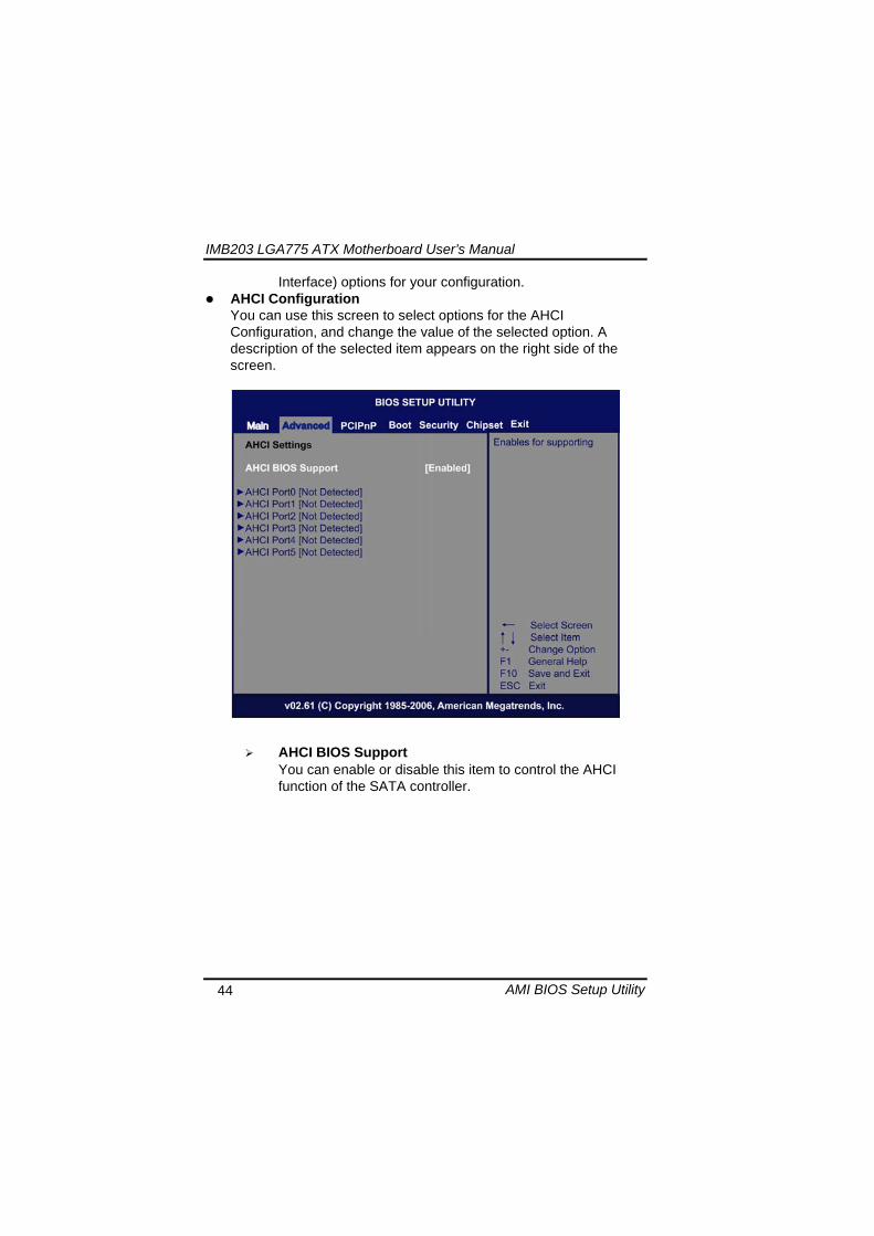
IMB203 LGA775 ATX Motherboard Userrsquos Manual
AMI BIOS Setup Utility 44
Interface) options for your configuration AHCI Configuration
You can use this screen to select options for the AHCI Configuration and change the value of the selected option A description of the selected item appears on the right side of the screen
AHCI BIOS Support You can enable or disable this item to control the AHCI function of the SATA controller
IMB203 LGA775 ATX Motherboard Userrsquos Manual
AMI BIOS Setup Utility 45
Intel iAMT Configuration You can use this screen to select options for the Intel iAMT Configuration and change the value of the selected option A description of the selected item appears on the right side of the screen
Intel iAMT Support
You can enable this item to support iAMT (active management technology) function to follow up the procedure for the access to AMI program screen
Unconfigure iAMTME Use this item to unconfigure the iAMTME settings
IMB203 LGA775 ATX Motherboard Userrsquos Manual
AMI BIOS Setup Utility 46
Intel VT-d Configuration You can use this screen to select options for the Intel VT-d Configuration and change the value of the selected option A description of the selected item appears on the right side of the screen
Intel VT-d Virtualization Technology for Directed IO (VT-d) extends Virtualization Technology (VT) roadmap by providing hardware assists for virtualization solution VT-d can help end users improve security and reliability of the systems and also improve performance of IO devices in virtualized environment Here are the options for your selection Disabled and Enabled
IMB203 LGA775 ATX Motherboard Userrsquos Manual
AMI BIOS Setup Utility 47
Remote Access Configuration You can use this screen to select options for the Remote Access Configuration and change the value of the selected option A description of the selected item appears on the right side of the screen
Remote Access Use this item to enable or disable the Remote Access function
IMB203 LGA775 ATX Motherboard Userrsquos Manual
AMI BIOS Setup Utility 48
PCI Express Configuration This screen shows the PCI Express Configuration and you can change its value A description of the selected item appears on the right side of the screen
Active State Power-Management
Use this item to enable or disable the function of Active State Power-Management to provide you with lower power consumption The default setting is Disabled
IMB203 LGA775 ATX Motherboard Userrsquos Manual
AMI BIOS Setup Utility 49
Trusted Computing You can use this screen to select options for the Trusted Computing and change the value of the selected option A description of the selected item appears on the right side of the screen
TCGTPM SUPPORT Use this item to control the Trusted Platform Module (TPM) function
IMB203 LGA775 ATX Motherboard Userrsquos Manual
AMI BIOS Setup Utility 50
USB Configuration You can use this screen to select options for the USB Configuration and change the value of the selected option A description of the selected item appears on the right side of the screen
USB Functions
This item allows you to enable or disable USB functions
Legacy USB Support Use this item to enable or disable support for USB device on legacy operating system The default setting is Enabled
USB 20 Controller Mode Use this item to configure the USB 20 controller The default setting is HiSpeed
BIOS EHCI Hand-Off Enabling this item provide the support for operating systems without an EHCI hand-off feature The default setting is Enabled
IMB203 LGA775 ATX Motherboard Userrsquos Manual
AMI BIOS Setup Utility 51
IMB203 LGA775 ATX Motherboard Userrsquos Manual
AMI BIOS Setup Utility 52
55 PCI PnP Menu The PCI PnP menu allows users to change the advanced settings for PCIPnP devices
Clear NVRAM
Use this item to clear the data in the NVRAM (CMOS) Here are the options for your selection No and Yes
Plug amp Play OS When the setting is No Use this item to configure all the devices in the system When the setting is Yes and if you install a Plug and Play operating system the operating system configures the Plug and Play devices not required for boot The default setting is No
IMB203 LGA775 ATX Motherboard Userrsquos Manual
AMI BIOS Setup Utility 53
PCI Latency Timer This item controls how long a PCI device can hold the PCI bus before another takes over The longer the latency the longer the PCI device can retain control of the bus before handing it over to another PCI device There are several options for your selection
Allocate IRQ to PCI VGA This item allows BIOS to choose an IRQ to assign for the PCI VGA card Here are the options for your selection No and Yes
Palette Snooping Some old graphic controllers need to ldquosnooprdquo on the VGA palette and then map it to their display as a way to provide boot information and VGA compatibility This item allows such snooping to take place Here are the options for your selection Disabled and Enabled
PCI IDE BusMaster This item is a toggle for the built-in driver that allows the onboard IDE controller to perform DMA (Direct Memory Access) transfer Here are the options for your selection Disabled and Enabled
OffBoard PCIISA IDE Card This item is for any other non-onboard PCIISA IDE controller adapter There are several options for your selection
IRQ3457910111415 These items will allow you to assign each system interrupt a type depending on the type of device using the interrupt The option ldquoAvailablerdquo means the IRQ is going to assign automatically Here are the options for your selection Available and Reserved
DMA Channel 013567 These items will allow you to assign each DMA channel a type depending on the type of device using the channel The option ldquoAvailablerdquo means the channel is going to assign automatically Here are the options for your selection Available and Reserved
IMB203 LGA775 ATX Motherboard Userrsquos Manual
AMI BIOS Setup Utility 54
56 Boot Menu The Boot menu allows users to change boot options of the system You can select any of the items in the left frame of the screen to go to the sub menus
Boot Settings Configuration Boot Device Priority Removable Drives
For items marked with ldquo rdquo please press ltEntergt for more options
IMB203 LGA775 ATX Motherboard Userrsquos Manual
AMI BIOS Setup Utility 55
Boot Settings Configuration
Quick Boot
Enabling this item lets the BIOS skip some power on self tests (POST) The default setting is Enabled
AddOn ROM Display Mode This item selects the display mode for option ROM The default setting is Force BIOS
Boot Num-Lock Use this item to select the power-on state for the NumLock The default setting is On
PS2 Mouse Support This item determines if the BIOS should reserve IRQ12 for the PS2 mouse or allow other devices to make use of this IRQ Here are the options for your selection Auto Enabled and Disabled
Wait For lsquoF1rsquo Of Error If this item is enabled the system waits for the F1 key to be pressed when error occurs The default setting is Enabled
Hit lsquoDELrsquo Message Display If this item is enabled the system displays the message
IMB203 LGA775 ATX Motherboard Userrsquos Manual
AMI BIOS Setup Utility 56
ldquoPress DEL to run Setuprdquo during POST The default setting is Enabled
Interrupt 19 Capture If this item is enabled this function makes the option ROMs to trap Interrupt 19 The default setting is Disabled
Boot Device Priority The Boot Device Priority screen specifies the boot device priority sequence from the available devices
IMB203 LGA775 ATX Motherboard Userrsquos Manual
AMI BIOS Setup Utility 57
Removable Drives Use this screen to view the removable drives in the system The BIOS will attempt to arrange the removable drive boot sequence automatically You can also change the booting sequence
IMB203 LGA775 ATX Motherboard Userrsquos Manual
AMI BIOS Setup Utility 58
57 Security Menu The Security menu allows users to change the security settings for the system
Supervisor Password
This item indicates whether a supervisor password has been set If the password has been installed Installed displays If not Not Installed displays
User Password This item indicates whether a user password has been set If the password has been installed Installed displays If not Not Installed displays
Change Supervisor Password Select this option and press ltEntergt to access the sub menu You can use the sub menu to change the supervisor password
Change User Password Select this option and press ltEntergt to access the sub menu You can use the sub menu to change the user password
IMB203 LGA775 ATX Motherboard Userrsquos Manual
AMI BIOS Setup Utility 59
58 Chipset Menu The Chipset menu allows users to change the advanced chipset settings You can select any of the items in the left frame of the screen to go to the sub menus
North Bridge Configuration South Bridge Configuration ME Subsystem Configuration
For items marked with ldquo rdquo please press ltEntergt for more options
IMB203 LGA775 ATX Motherboard Userrsquos Manual
AMI BIOS Setup Utility 60
North Bridge Configuration
Memory Remap Feature
Use this item to enable or disable the remapping of the overlapped PCI memory above the total physical memory Only 64-bit OS supports this function
DRAM Frequency This item allows you to control the Memory Clock
Configure DRAM Timing by SPD This item can enable or disable DRAM timing by SPD (Serial Presence Detect) device which is a small EEPROM chip on the memory module containing important information about the module speed size addressing mode and various parameters
Memory Hole You can reserve this area of system memory for ISA adapter ROM When this area is reserved it cannot be cached Check the user information of peripherals that need to use this area o f system memory for the memory requirements Here are the options Disabled and 15M-16M
IMB203 LGA775 ATX Motherboard Userrsquos Manual
AMI BIOS Setup Utility 61
Initiate Graphic Adapter When using multiple graphics cards this item can select which graphics controller to be the primary display device during boot
IGD Graphics Mode Select This item allows you to select the amount of system memory used by the internal graphics device
PEG Port ConfigurationPEG Port This item is a toggle to enable or disable the PCI Express port Here are the options for your selection Auto and Disabled
Video Function Configuration Press ltEntergt for the sub-menu for setting up video function
IMB203 LGA775 ATX Motherboard Userrsquos Manual
AMI BIOS Setup Utility 62
South Bridge Configuration
GbE Wake Up From S5 This item specifies whether the system will be awakened from the S5 power
HDA Controller This item allows you to enable or disable the HD audio support
Restore on AC Power Loss This item can control how the PC will behave once power is restored following a power outage or other unexpected shutdown
PCIE Port Configuration This item allows you to set or disable the PCI Express Ports
IMB203 LGA775 ATX Motherboard Userrsquos Manual
AMI BIOS Setup Utility 63
ME Subsystem Configuration
It is strongly recommended that you do not modify these options unless you are an advanced user
IMB203 LGA775 ATX Motherboard Userrsquos Manual
AMI BIOS Setup Utility 64
59 Exit Menu The Exit menu allows users to load your system configuration with optimal or failsafe default values
Save Changes and Exit
When you have completed the system configuration changes select this option to leave Setup and reboot the computer so the new system configuration parameters can take effect Select Save Changes and Exit from the Exit menu and press ltEntergt Select Ok to save changes and exit
Discard Changes and Exit Select this option to quit Setup without making any permanent changes to the system configuration Select Discard Changes and Exit from the Exit menu and press ltEntergt Select Ok to discard changes and exit
Load Optimal Defaults It automatically sets all Setup options to a complete set of default settings when you select this option The Optimal settings are designed for maximum system performance but may not work best for all computer applications In particular do not use the Optimal Setup options if your
IMB203 LGA775 ATX Motherboard Userrsquos Manual
AMI BIOS Setup Utility 65
computer is experiencing system configuration problems Select Load Optimal Defaults from the Exit menu and press ltEntergt
Load Fail-Safe Defaults It automatically sets all Setup options to a complete set of default settings when you select this option The Fail-Safe settings are designed for maximum system stability but not maximum performance Select the Fail-Safe Setup options if your computer is experiencing system configuration problems Select Load Fail-Safe Defaults from the Exit menu and press ltEntergt Select Ok to load Fail-Safe defaults
IMB203 LGA775 ATX Motherboard Userrsquos Manual
AMI BIOS Setup Utility 66
MEMO
IMB203 LGA775 ATX Motherboard Userrsquos Manual
Installation of Drivers 67
CHPATER 6 INSTALLATION OF DRIVERS
The device drivers are located on the Product Information CD-ROM that comes with the IMB203 Series package The auto-run function of drivers will guide you to install the utilities and device drivers under a Windows system You can follow the onscreen instructions to install these devices
Chipse VGA LAN Audio iAMT MEI
61 Installing Chipset Driver 1 Run the SETUPEXE program from the driver directory in
your driver CD Click ldquoNextrdquo to next step
IMB203 LGA775 ATX Motherboard Userrsquos Manual
Installation of Drivers 68
2 An Intelreg License Agreement appears to show you the important information Click ldquoYesrdquo to next step
3 Refer to the Readme file below to view the system requirements and installation information
IMB203 LGA775 ATX Motherboard Userrsquos Manual
Installation of Drivers 69
3-1 Please wait while running the following setup operations
3-2 Please wait while running the following setup operations
IMB203 LGA775 ATX Motherboard Userrsquos Manual
Installation of Drivers 70
4 Click ldquoFinishrdquo to complete the setup process
5 You will be asked to reboot your computer when the installation is completed Please click ldquoYes I want to restart my computer nowrdquo if you donrsquot need to install any other drivers Otherwise please click ldquoNo I will restart my computer laterrdquo and go on next step
IMB203 LGA775 ATX Motherboard Userrsquos Manual
Installation of Drivers 71
62 Installing VGA Driver 1 Run the SETUPEXE program from the driver directory in
your driver CD Click ldquoNextrdquo to next step
2 An Intelreg License Agreement appears to show you the
important information Click ldquoYesrdquo to next step
IMB203 LGA775 ATX Motherboard Userrsquos Manual
Installation of Drivers 72
3 The message of Readme File Information appears to show you the system requirements and installation information Please click ldquoNextrdquo
4 Please wait while running the following setup operations
When this message appears please click ldquoNextrdquo
IMB203 LGA775 ATX Motherboard Userrsquos Manual
Installation of Drivers 73
5 Click ldquoFinishrdquo to complete the setup process
6 You will be asked to reboot your computer when the installation is completed Please click ldquoYes I want to restart my computer nowrdquo if you donrsquot need to install any other drivers Otherwise please click ldquoNo I will restart my computer laterrdquo and click ldquoFinishrdquo to complete the installation
IMB203 LGA775 ATX Motherboard Userrsquos Manual
Installation of Drivers 74
63 Installing LAN Driver
11 Run the InstallShield Wizard for Network Connections from
the driver directory in your driver CD Click ldquoNextrdquo to next step
IMB203 LGA775 ATX Motherboard Userrsquos Manual
Installation of Drivers 75
12 An Intelreg License Agreement appears to show you the important information Click ldquoYesrdquo to next step
13 A Setup Options window appears that you can select the
program features you want to install
IMB203 LGA775 ATX Motherboard Userrsquos Manual
Installation of Drivers 76
2 Click ldquoInstallrdquo to start the installation
3 Please wait while running the following installation operation
IMB203 LGA775 ATX Motherboard Userrsquos Manual
Installation of Drivers 77
4 Click ldquoFinishrdquo to complete the installation
Note The Driver item [Wake on Directed Packet] default is Enabled under Windows Vista
格式化 字型 (符號) Arial
格式化 字型 (符號) Arial
格式化 字型 斜體 字型色彩 黑色 (符號) Arial 非加寬 緊縮
格式化 字型 斜體 字型色彩 黑色 (符號) Arial 非加寬 緊縮
格式化 字型 (符號) Arial 非加寬 緊縮
IMB203 LGA775 ATX Motherboard Userrsquos Manual
Installation of Drivers 78
64 Installing AUDIO Driver 1 Run the InstallShield Wizard for Realtek High Definition
Audio Driver from the driver directory in your driver CD Click ldquoNextrdquo to next step
IMB203 LGA775 ATX Motherboard Userrsquos Manual
Installation of Drivers 79
2 Click ldquoInstallrdquo to start the installation and wait while running the installation operation
3 Click ldquoFinishrdquo to complete the installation
IMB203 LGA775 ATX Motherboard Userrsquos Manual
Installation of Drivers 80
65 Installing iAMT (Active Management Technology) Driver
Note You must download and properly install the required NET version 35 provided from a separate downloading of the actual FimwareTools kit releases posted on VIP prior to loading the MEILMS Driver stack
651 LMS_SOL Setup
1 Run the setup program to install Intelreg Active Management Technology onto your computer It is strongly recommended that you exit all programs before continuing Click ldquoNextrdquo to next step
格式化 字型 (符號) Arial
格式化 字型 (符號) Arial 非加寬 緊縮
IMB203 LGA775 ATX Motherboard Userrsquos Manual
Installation of Drivers 81
2 An Intelreg license agreement appears that you need to continue the setup program by clicking ldquoYesrdquo to accept the terms
IMB203 LGA775 ATX Motherboard Userrsquos Manual
Installation of Drivers 82
3 Refer to the Readme file below to view the system requirements and installation information Click ldquoNextrdquo to next setup
4 Please wait while running the following installation operation
IMB203 LGA775 ATX Motherboard Userrsquos Manual
Installation of Drivers 83
5 Click ldquoFinishrdquo to complete the installation
IMB203 LGA775 ATX Motherboard Userrsquos Manual
Installation of Drivers 84
652 LMS_SOL_IS Setup
1 Run the setup program to install Intelreg Active Management Technology onto your computer It is strongly recommended that you exit all programs before continuing Click ldquoNextrdquo to next step
IMB203 LGA775 ATX Motherboard Userrsquos Manual
Installation of Drivers 85
2 An Intelreg license agreement appears that you need to continue the setup program by clicking ldquoYesrdquo to accept the terms
IMB203 LGA775 ATX Motherboard Userrsquos Manual
Installation of Drivers 86
3 Refer to the Readme file below to view the system requirements and installation information Click ldquoNextrdquo to next setup
4 Please wait while running the following installation operation
IMB203 LGA775 ATX Motherboard Userrsquos Manual
Installation of Drivers 87
5 Click ldquoFinishrdquo to complete the installation
IMB203 LGA775 ATX Motherboard Userrsquos Manual
Installation of Drivers 88
66 Installing MEI (Management Engine Interface) Driver
Note You must download and properly install the required NET version 35 provided from a separate downloading of the actual FimwareTools kit releases posted on VIP prior to loading the MEILMS Driver stack
1 Run the setup program to install Intelreg Management Engine
Interface onto your computer It is strongly recommended that you exit all programs before continuing Click ldquoNextrdquo to next step
格式化 字型 (符號) Arial
格式化 字型 (符號) Arial 非加寬 緊縮
IMB203 LGA775 ATX Motherboard Userrsquos Manual
Installation of Drivers 89
2 An Intelreg license agreement appears that you need to continue the setup program by clicking ldquoYesrdquo to accept the terms
IMB203 LGA775 ATX Motherboard Userrsquos Manual
Installation of Drivers 90
3 Refer to the Readme file below to view the system requirements and installation information Click ldquoNextrdquo to next setup
4 Please wait while running the following installation operation
IMB203 LGA775 ATX Motherboard Userrsquos Manual
Installation of Drivers 91
5 Click ldquoFinishrdquo to complete the installation
IMB203 LGA775 ATX Motherboard Userrsquos Manual
Installation of Drivers 92
MEMO
IMB203 LGA775 ATX Motherboard Userrsquos Manual
Watchdog Timer 93
APPENDIX A WATCHDOG TIMER
Watchdog Timer Setting After the system stops working for a while it can be auto-reset by the Watchdog Timer The integrated Watchdog Timer can be set up in the system reset mode by program
Using the Watchdog Function Start darr Un-Lock WDT O 2E 87 Un-lock super IO
O 2E 87 Un-lock super IO darr Set WDT Function O 2E 2D O 2F 20 Select Logic device O 2E 07 O 2F 08 darr Activate WDT O 2E 30
O 2F 01 Set Second or Minute O 2E F5
O 2F N N=00 or 08(See below table) darr Set base timer O 2E F6
O 2F M=000102hellipFF(Hex) Value=0 to 255 darr WDT counting
re-set timer O 2E F6
O 2F M M=000102hellipFF(See below table) darr
格式化
格式化 項目符號及編號
格式化 項目符號及編號
格式化 字型 8 點 字型色彩黑色
格式化 字型 8 點 字型色彩黑色
格式化 定位點 1257 字元左 + 不在 1012 字元 + 1386字元
格式化 字型 8 點 字型色彩黑色
格式化 定位點 1257 字元左 + 不在 134 字元 + 1362字元
格式化 字型色彩 黑色
格式化 字型色彩 黑色
刪除
IMB203 LGA775 ATX Motherboard Userrsquos Manual
Watchdog Timer 94
IF No re-set timer WDT time-out generate RESET IF to disable WDT O 2E 30
O 2F 00 Can be disable at any time
N=00
M= 00h Time-out Disable 01h Time-out occurs after 1 second 02h Time-out occurs after 2 second 03h Time-out occurs after 3 second helliphelliphelliphelliphelliphelliphelliphelliphellip FFh Time-out occurs after 255 second
N=08
M= 00h Time-out Disable 01h Time-out occurs after 1 minute 02h Time-out occurs after 2 minutes 03h Time-out occurs after 3 minutes helliphelliphelliphelliphelliphelliphelliphelliphellip
FFh Time-out occurs after 255 minutes
格式化 字型色彩 黑色
格式化 字型色彩 黑色
IMB203 LGA775 ATX Motherboard Userrsquos Manual
PCI IRQ Routing 95
APPENDIX B PCI IRQ ROUTING
PICMG PCI IRQ Routing
Device ID Slot Int
PCI Slot 0 31 0 BCDA PCI Slot 1 30 1 CDAB PCI Slot 2 29 2 DABC PCI Slot 3 28 3 ABCD
IMB203 LGA775 ATX Motherboard Userrsquos Manual
PCI IRQ Routing 96
MEMO
IMB203 LGA775 ATX Motherboard Userrsquos Manual
Configuring SATA for RAID Function 97
APPENDIX C CONFIGURING SATA FOR RAID
FUNCTION
Configuring SATA Hard Drive(s) for RAID Function (Controller IntelregICH10DODO DH only) Please follow up the steps below to configure SATA hard drive(s) (1) Install SATA hard drive(s) in your system (2) Enter the BIOS Setup to configure SATA controller mode and boot
sequence (3) Configure RAID by the RAID BIOS (4) Install the SATA controller driver during the OS installation Before you begin the SATA configuration please prepare (a) Two SATA hard drives (to ensure optimal performance it is
recommended that you use two hard drives with identical model and capacity) If you do not want to create RAID with the SATA controller you may prepare only one hard drive
(b) An empty formatted floppy disk (c) Windows XP setup disk (1) Installing SATA hard drive(s) in your system
Connect one end of the SATA signal cable to the rear of the SATA hard drive and the other end to available SATA port(s) on the board Then connect the power connector of power supply to the hard drive
(2) Configuring SATA controller mode and boot sequence by the BIOS Setup You have to make sure whether the SATA controller is configured correctly by system BIOS Setup and set up BIOS boot sequence for the SATA hard drive(s)
IMB203 LGA775 ATX Motherboard Userrsquos Manual
Configuring SATA for RAID Function 98
(2)-1-1 Turn on your system and then press the Del button to enter BIOS Setup during running POST (Power-On Self Test) If you want to create RAID just go to the Advanced Settings menuIDE configuration select the Configure SATA1 as and press ltEntergt for more options
IMB203 LGA775 ATX Motherboard Userrsquos Manual
Configuring SATA for RAID Function 99
(2)-1-2 A list of options appears please select RAID
IMB203 LGA775 ATX Motherboard Userrsquos Manual
Configuring SATA for RAID Function 100
(2)-2 Set CDROM for First Boot Device under the Boot Settings menu to boot CD-ROM after system restarts
(2)-3 Save and exit the BIOS Setup
IMB203 LGA775 ATX Motherboard Userrsquos Manual
Configuring SATA for RAID Function 101
(3) Configuring RAID by the RAID BIOS Enter the RAID BIOS setup utility to configure a RAID array Skip this step and proceed to Section 4 if you do not want to create a RAID (3)-1 After the POST memory testing and before the operating
system booting a message Press ltCtrl-Igt to enter Configuration Utility shows up accordingly press ltCTRL+ Igt to enter the RAID BIOS setup utility
(3)-2 After you press ltCTRL+ Igt the Create RAID Volume screen will appear If you want to create a RAID array select the Create RAID Volume option in the Main Menu and press ENTER
IMB203 LGA775 ATX Motherboard Userrsquos Manual
Configuring SATA for RAID Function 102
(3)-3-1 After entering the CREATE VOLUME MENU screen you can type the disk array name with 1~16 letters (letters cannot be special characters) in the item ldquoNamerdquo
(3)-3-2 When finished press ENTER to select a RAID level There are three RAID levels RAID0 RAID1 and RAID5 amp RAID10 Select a RAID level and press ENTER
IMB203 LGA775 ATX Motherboard Userrsquos Manual
Configuring SATA for RAID Function 103
(3)-4 Set the stripe block size The KB is the standard unit of stripe block size The stripe block size can be 4KB to 128KB After the setting press ENTER for the array capacity
(3)-5 After setting all the items on the menu select Create Volume
and press ENTER to start creating the RAID array
IMB203 LGA775 ATX Motherboard Userrsquos Manual
Configuring SATA for RAID Function 104
(3)-6 When prompting the confirmation press ldquoYldquo to create this volume or ldquoNldquo to cancel the creation
After the creation is completed you can see detailed information about the RAID Array in the DISKVOLUME INFORMATION section including RAID mode disk block size disk name and disk capacity etc
IMB203 LGA775 ATX Motherboard Userrsquos Manual
Configuring SATA for RAID Function 105
Delete RAID Volume If you want to delete a RAID volume select the Delete RAID Volume option in Main Menu Press ENTER and follow on-screen instructions
Please press [ESC] to exit the RAID BIOS utility Now you can proceed to install a SATA driver controller and the operating system
IMB203 LGA775 ATX Motherboard Userrsquos Manual
Configuring SATA for RAID Function 106
(4) Making a SATA Driver Disk To install the operating system onto a serial ATA hard disk successfully you need to install the SATA controller driver during the OS installation Without the driver the hard disk may not be recognized during the Windows setup process First of all please format a blank floppy disk Secondly follow up these steps below to produce a SATA driver disk Users can insert the Driver CD and the formatted blank floppy disk in another system And then please copy all of file of the f6flpy32 folder in the Driver CD to a floppy disk Note Please copy all of file of the f6flpy64 folder if installing 64-bit
Windows Operating System
IMB203 LGA775 ATX Motherboard Userrsquos Manual
Configuring SATA for RAID Function 107
(5) Installing the SATA controller driver during the OS installation Now the SATA driver disk is ready and BIOS settings configured you can proceed to install Windows 2000XP onto your SATA hard drive using the SATA driver Here is an example for Windows XP installation (5)-1 Restart your system to boot the Windows 2000XP Setup disk
and press F6 button as soon as you see the message Press F6 if you need to install a 3rd party SCSI or RAID driver After pressing the F6 button there will be a few moments for some files being loaded before next screen appears
IMB203 LGA775 ATX Motherboard Userrsquos Manual
Configuring SATA for RAID Function 108
(5)-2 When you see the screen below insert the floppy disk containing the SATA driver and press ldquoSrdquo
(5)-3 If the Setup correctly recognizes the driver of the floppy disk
a controller menu will appear below Use the ARROW keys to select Intel(R) ICH8RICH9RICH10RDO SATA RAID Controller and press ENTER Then it will begin to load the SATA driver from the floppy disk
IMB203 LGA775 ATX Motherboard Userrsquos Manual
Configuring SATA for RAID Function 109
Note If a message on the screen saying that one or some file(s) cannot be found please check the floppy disk or copy the correct SATA driver again from the driver CD
IMB203 LGA775 ATX Motherboard Userrsquos Manual
Configuring SATA for RAID Function 110
MEMO
IMB203 LGA775 ATX Motherboard Userrsquos Manual
iAMT Settings 111
APPENDIX D iAMT SETTINGS
The Intelreg Active Management Technology (Intelreg iAMT) has decreased a major barrier to IT efficiency that uses built-in platform capabilities and popular third-party management and security applications to allow IT a better discovering healing and protection their networked computing assets In order to utilize Intel iAMT you must enter the ME BIOS (CTRL + P during system startup) change the ME BIOS password and then select ldquoIntelreg iAMTrdquo as the manageability feature
D1 Entering MEBx 1 You must go to BIOS TO start iAMT function 2 Exit from BIOS after starting iAMT and press Ctrl+P to enter MEBx Setting
It is better to press Ctrl+P before the screen popping out
格式化
IMB203 LGA775 ATX Motherboard Userrsquos Manual
iAMT Settings 112
D2 Set amp Change Password 1 You will be asked to set a password when first log in The default
password is lsquoadminrsquo
2 You will be asked to change the password before setting ME
Change Password
IMB203 LGA775 ATX Motherboard Userrsquos Manual
iAMT Settings 113
3 You must confirm your new password while revising (as Remark 1)
Remark 1 The new password must contain (example 11qqQQ) (default value)
Eight characters
One upper case
One lower case
One number
One special symbol such as $ or
( excepted)
Underline ( _ ) and space are valid characters for password but they wonrsquot make higher complexity
IMB203 LGA775 ATX Motherboard Userrsquos Manual
iAMT Settings 114
D3 Intelreg iAMT Settings 1 Select Intelreg iAMT Configuration and press ltENTERgt
2 Key in the Host Name If Intelreg iAMT set to lsquoDHCPlsquo the Host name must be identical to the operating system mechanic
IMB203 LGA775 ATX Motherboard Userrsquos Manual
iAMT Settings 115
3 Select TCPIP to get into Network interface and set it to lsquoENABLEDrsquo into DHCP Mode and set it to lsquoDISABLEDrsquo (as Remark 2) into Domain name and set the Intel Management Engine domain name such as lsquoAMTintelcomrsquo
(3-1)
(3-2)
IMB203 LGA775 ATX Motherboard Userrsquos Manual
iAMT Settings 116
Remark 2 DHCP Mode lsquoDISABLEDlsquo if DHCP Mode is disabled you can make the following settings
IP address
Subnet mask
IMB203 LGA775 ATX Motherboard Userrsquos Manual
iAMT Settings 117
Default Gateway address
Preferred DNS address
IMB203 LGA775 ATX Motherboard Userrsquos Manual
iAMT Settings 118
Alternate DNS address
Domain name
4 Exit from MEBx after completing the iAMT settings
IMB203 LGA775 ATX Motherboard Userrsquos Manual
iAMT Settings 119
D4 iAMT Web Console 1 From a web browser please type http(IP ADDRESS)16992
which connects to iAMT Web Example http1014021416992
2 To log on you will be required to type in username and password
for access to the Web
USER admin (default value)
PASS (MEBx password)
IMB203 LGA775 ATX Motherboard Userrsquos Manual
iAMT Settings 120
3 Enter the iAMT Web
4 Click Remote Control and select commands on the right side
IMB203 LGA775 ATX Motherboard Userrsquos Manual
iAMT Settings 121
5 When you have finished using the iAMT Web console close the Web browser
IMB203 LGA775 ATX Motherboard Userrsquos Manual
iAMT Settings 122
MEMO
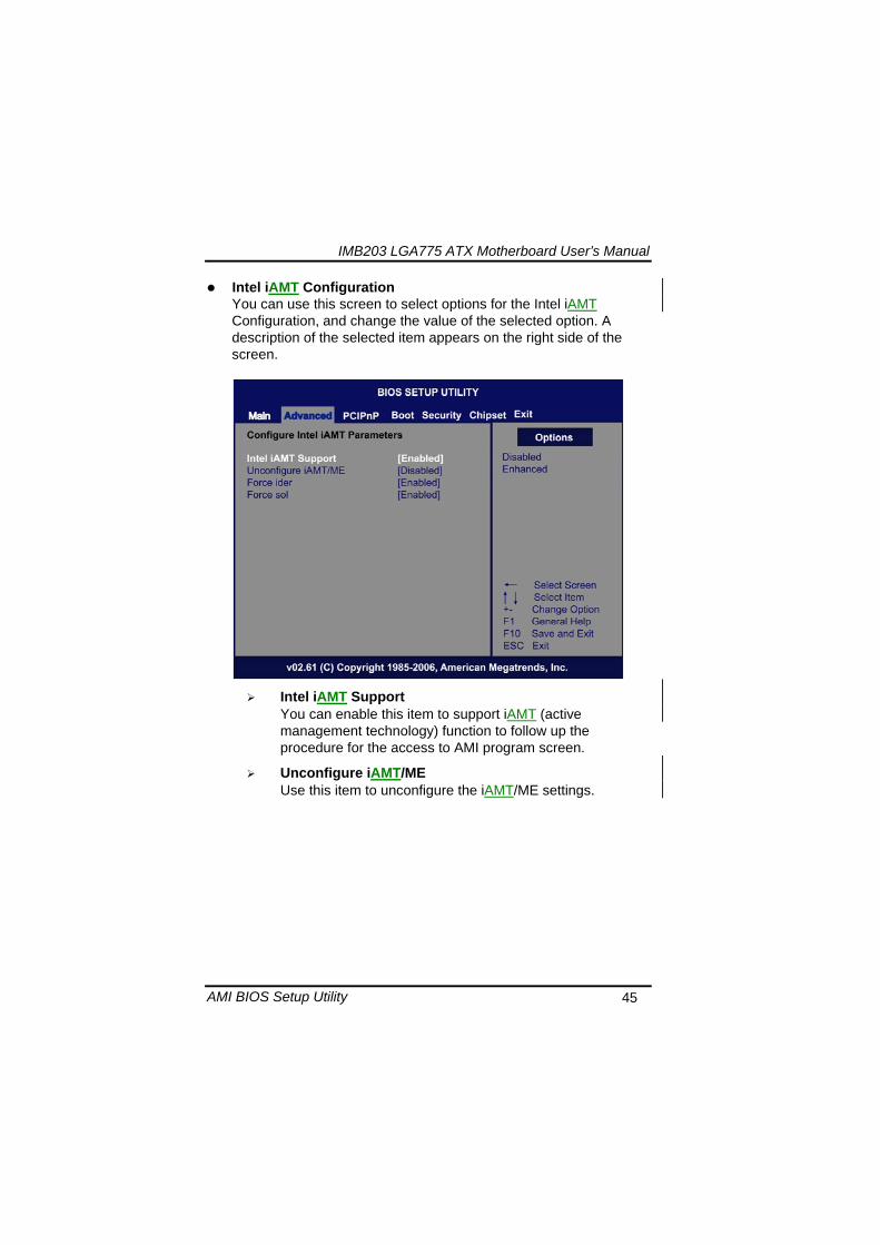
IMB203 LGA775 ATX Motherboard Userrsquos Manual
AMI BIOS Setup Utility 45
Intel iAMT Configuration You can use this screen to select options for the Intel iAMT Configuration and change the value of the selected option A description of the selected item appears on the right side of the screen
Intel iAMT Support
You can enable this item to support iAMT (active management technology) function to follow up the procedure for the access to AMI program screen
Unconfigure iAMTME Use this item to unconfigure the iAMTME settings
IMB203 LGA775 ATX Motherboard Userrsquos Manual
AMI BIOS Setup Utility 46
Intel VT-d Configuration You can use this screen to select options for the Intel VT-d Configuration and change the value of the selected option A description of the selected item appears on the right side of the screen
Intel VT-d Virtualization Technology for Directed IO (VT-d) extends Virtualization Technology (VT) roadmap by providing hardware assists for virtualization solution VT-d can help end users improve security and reliability of the systems and also improve performance of IO devices in virtualized environment Here are the options for your selection Disabled and Enabled
IMB203 LGA775 ATX Motherboard Userrsquos Manual
AMI BIOS Setup Utility 47
Remote Access Configuration You can use this screen to select options for the Remote Access Configuration and change the value of the selected option A description of the selected item appears on the right side of the screen
Remote Access Use this item to enable or disable the Remote Access function
IMB203 LGA775 ATX Motherboard Userrsquos Manual
AMI BIOS Setup Utility 48
PCI Express Configuration This screen shows the PCI Express Configuration and you can change its value A description of the selected item appears on the right side of the screen
Active State Power-Management
Use this item to enable or disable the function of Active State Power-Management to provide you with lower power consumption The default setting is Disabled
IMB203 LGA775 ATX Motherboard Userrsquos Manual
AMI BIOS Setup Utility 49
Trusted Computing You can use this screen to select options for the Trusted Computing and change the value of the selected option A description of the selected item appears on the right side of the screen
TCGTPM SUPPORT Use this item to control the Trusted Platform Module (TPM) function
IMB203 LGA775 ATX Motherboard Userrsquos Manual
AMI BIOS Setup Utility 50
USB Configuration You can use this screen to select options for the USB Configuration and change the value of the selected option A description of the selected item appears on the right side of the screen
USB Functions
This item allows you to enable or disable USB functions
Legacy USB Support Use this item to enable or disable support for USB device on legacy operating system The default setting is Enabled
USB 20 Controller Mode Use this item to configure the USB 20 controller The default setting is HiSpeed
BIOS EHCI Hand-Off Enabling this item provide the support for operating systems without an EHCI hand-off feature The default setting is Enabled
IMB203 LGA775 ATX Motherboard Userrsquos Manual
AMI BIOS Setup Utility 51
IMB203 LGA775 ATX Motherboard Userrsquos Manual
AMI BIOS Setup Utility 52
55 PCI PnP Menu The PCI PnP menu allows users to change the advanced settings for PCIPnP devices
Clear NVRAM
Use this item to clear the data in the NVRAM (CMOS) Here are the options for your selection No and Yes
Plug amp Play OS When the setting is No Use this item to configure all the devices in the system When the setting is Yes and if you install a Plug and Play operating system the operating system configures the Plug and Play devices not required for boot The default setting is No
IMB203 LGA775 ATX Motherboard Userrsquos Manual
AMI BIOS Setup Utility 53
PCI Latency Timer This item controls how long a PCI device can hold the PCI bus before another takes over The longer the latency the longer the PCI device can retain control of the bus before handing it over to another PCI device There are several options for your selection
Allocate IRQ to PCI VGA This item allows BIOS to choose an IRQ to assign for the PCI VGA card Here are the options for your selection No and Yes
Palette Snooping Some old graphic controllers need to ldquosnooprdquo on the VGA palette and then map it to their display as a way to provide boot information and VGA compatibility This item allows such snooping to take place Here are the options for your selection Disabled and Enabled
PCI IDE BusMaster This item is a toggle for the built-in driver that allows the onboard IDE controller to perform DMA (Direct Memory Access) transfer Here are the options for your selection Disabled and Enabled
OffBoard PCIISA IDE Card This item is for any other non-onboard PCIISA IDE controller adapter There are several options for your selection
IRQ3457910111415 These items will allow you to assign each system interrupt a type depending on the type of device using the interrupt The option ldquoAvailablerdquo means the IRQ is going to assign automatically Here are the options for your selection Available and Reserved
DMA Channel 013567 These items will allow you to assign each DMA channel a type depending on the type of device using the channel The option ldquoAvailablerdquo means the channel is going to assign automatically Here are the options for your selection Available and Reserved
IMB203 LGA775 ATX Motherboard Userrsquos Manual
AMI BIOS Setup Utility 54
56 Boot Menu The Boot menu allows users to change boot options of the system You can select any of the items in the left frame of the screen to go to the sub menus
Boot Settings Configuration Boot Device Priority Removable Drives
For items marked with ldquo rdquo please press ltEntergt for more options
IMB203 LGA775 ATX Motherboard Userrsquos Manual
AMI BIOS Setup Utility 55
Boot Settings Configuration
Quick Boot
Enabling this item lets the BIOS skip some power on self tests (POST) The default setting is Enabled
AddOn ROM Display Mode This item selects the display mode for option ROM The default setting is Force BIOS
Boot Num-Lock Use this item to select the power-on state for the NumLock The default setting is On
PS2 Mouse Support This item determines if the BIOS should reserve IRQ12 for the PS2 mouse or allow other devices to make use of this IRQ Here are the options for your selection Auto Enabled and Disabled
Wait For lsquoF1rsquo Of Error If this item is enabled the system waits for the F1 key to be pressed when error occurs The default setting is Enabled
Hit lsquoDELrsquo Message Display If this item is enabled the system displays the message
IMB203 LGA775 ATX Motherboard Userrsquos Manual
AMI BIOS Setup Utility 56
ldquoPress DEL to run Setuprdquo during POST The default setting is Enabled
Interrupt 19 Capture If this item is enabled this function makes the option ROMs to trap Interrupt 19 The default setting is Disabled
Boot Device Priority The Boot Device Priority screen specifies the boot device priority sequence from the available devices
IMB203 LGA775 ATX Motherboard Userrsquos Manual
AMI BIOS Setup Utility 57
Removable Drives Use this screen to view the removable drives in the system The BIOS will attempt to arrange the removable drive boot sequence automatically You can also change the booting sequence
IMB203 LGA775 ATX Motherboard Userrsquos Manual
AMI BIOS Setup Utility 58
57 Security Menu The Security menu allows users to change the security settings for the system
Supervisor Password
This item indicates whether a supervisor password has been set If the password has been installed Installed displays If not Not Installed displays
User Password This item indicates whether a user password has been set If the password has been installed Installed displays If not Not Installed displays
Change Supervisor Password Select this option and press ltEntergt to access the sub menu You can use the sub menu to change the supervisor password
Change User Password Select this option and press ltEntergt to access the sub menu You can use the sub menu to change the user password
IMB203 LGA775 ATX Motherboard Userrsquos Manual
AMI BIOS Setup Utility 59
58 Chipset Menu The Chipset menu allows users to change the advanced chipset settings You can select any of the items in the left frame of the screen to go to the sub menus
North Bridge Configuration South Bridge Configuration ME Subsystem Configuration
For items marked with ldquo rdquo please press ltEntergt for more options
IMB203 LGA775 ATX Motherboard Userrsquos Manual
AMI BIOS Setup Utility 60
North Bridge Configuration
Memory Remap Feature
Use this item to enable or disable the remapping of the overlapped PCI memory above the total physical memory Only 64-bit OS supports this function
DRAM Frequency This item allows you to control the Memory Clock
Configure DRAM Timing by SPD This item can enable or disable DRAM timing by SPD (Serial Presence Detect) device which is a small EEPROM chip on the memory module containing important information about the module speed size addressing mode and various parameters
Memory Hole You can reserve this area of system memory for ISA adapter ROM When this area is reserved it cannot be cached Check the user information of peripherals that need to use this area o f system memory for the memory requirements Here are the options Disabled and 15M-16M
IMB203 LGA775 ATX Motherboard Userrsquos Manual
AMI BIOS Setup Utility 61
Initiate Graphic Adapter When using multiple graphics cards this item can select which graphics controller to be the primary display device during boot
IGD Graphics Mode Select This item allows you to select the amount of system memory used by the internal graphics device
PEG Port ConfigurationPEG Port This item is a toggle to enable or disable the PCI Express port Here are the options for your selection Auto and Disabled
Video Function Configuration Press ltEntergt for the sub-menu for setting up video function
IMB203 LGA775 ATX Motherboard Userrsquos Manual
AMI BIOS Setup Utility 62
South Bridge Configuration
GbE Wake Up From S5 This item specifies whether the system will be awakened from the S5 power
HDA Controller This item allows you to enable or disable the HD audio support
Restore on AC Power Loss This item can control how the PC will behave once power is restored following a power outage or other unexpected shutdown
PCIE Port Configuration This item allows you to set or disable the PCI Express Ports
IMB203 LGA775 ATX Motherboard Userrsquos Manual
AMI BIOS Setup Utility 63
ME Subsystem Configuration
It is strongly recommended that you do not modify these options unless you are an advanced user
IMB203 LGA775 ATX Motherboard Userrsquos Manual
AMI BIOS Setup Utility 64
59 Exit Menu The Exit menu allows users to load your system configuration with optimal or failsafe default values
Save Changes and Exit
When you have completed the system configuration changes select this option to leave Setup and reboot the computer so the new system configuration parameters can take effect Select Save Changes and Exit from the Exit menu and press ltEntergt Select Ok to save changes and exit
Discard Changes and Exit Select this option to quit Setup without making any permanent changes to the system configuration Select Discard Changes and Exit from the Exit menu and press ltEntergt Select Ok to discard changes and exit
Load Optimal Defaults It automatically sets all Setup options to a complete set of default settings when you select this option The Optimal settings are designed for maximum system performance but may not work best for all computer applications In particular do not use the Optimal Setup options if your
IMB203 LGA775 ATX Motherboard Userrsquos Manual
AMI BIOS Setup Utility 65
computer is experiencing system configuration problems Select Load Optimal Defaults from the Exit menu and press ltEntergt
Load Fail-Safe Defaults It automatically sets all Setup options to a complete set of default settings when you select this option The Fail-Safe settings are designed for maximum system stability but not maximum performance Select the Fail-Safe Setup options if your computer is experiencing system configuration problems Select Load Fail-Safe Defaults from the Exit menu and press ltEntergt Select Ok to load Fail-Safe defaults
IMB203 LGA775 ATX Motherboard Userrsquos Manual
AMI BIOS Setup Utility 66
MEMO
IMB203 LGA775 ATX Motherboard Userrsquos Manual
Installation of Drivers 67
CHPATER 6 INSTALLATION OF DRIVERS
The device drivers are located on the Product Information CD-ROM that comes with the IMB203 Series package The auto-run function of drivers will guide you to install the utilities and device drivers under a Windows system You can follow the onscreen instructions to install these devices
Chipse VGA LAN Audio iAMT MEI
61 Installing Chipset Driver 1 Run the SETUPEXE program from the driver directory in
your driver CD Click ldquoNextrdquo to next step
IMB203 LGA775 ATX Motherboard Userrsquos Manual
Installation of Drivers 68
2 An Intelreg License Agreement appears to show you the important information Click ldquoYesrdquo to next step
3 Refer to the Readme file below to view the system requirements and installation information
IMB203 LGA775 ATX Motherboard Userrsquos Manual
Installation of Drivers 69
3-1 Please wait while running the following setup operations
3-2 Please wait while running the following setup operations
IMB203 LGA775 ATX Motherboard Userrsquos Manual
Installation of Drivers 70
4 Click ldquoFinishrdquo to complete the setup process
5 You will be asked to reboot your computer when the installation is completed Please click ldquoYes I want to restart my computer nowrdquo if you donrsquot need to install any other drivers Otherwise please click ldquoNo I will restart my computer laterrdquo and go on next step
IMB203 LGA775 ATX Motherboard Userrsquos Manual
Installation of Drivers 71
62 Installing VGA Driver 1 Run the SETUPEXE program from the driver directory in
your driver CD Click ldquoNextrdquo to next step
2 An Intelreg License Agreement appears to show you the
important information Click ldquoYesrdquo to next step
IMB203 LGA775 ATX Motherboard Userrsquos Manual
Installation of Drivers 72
3 The message of Readme File Information appears to show you the system requirements and installation information Please click ldquoNextrdquo
4 Please wait while running the following setup operations
When this message appears please click ldquoNextrdquo
IMB203 LGA775 ATX Motherboard Userrsquos Manual
Installation of Drivers 73
5 Click ldquoFinishrdquo to complete the setup process
6 You will be asked to reboot your computer when the installation is completed Please click ldquoYes I want to restart my computer nowrdquo if you donrsquot need to install any other drivers Otherwise please click ldquoNo I will restart my computer laterrdquo and click ldquoFinishrdquo to complete the installation
IMB203 LGA775 ATX Motherboard Userrsquos Manual
Installation of Drivers 74
63 Installing LAN Driver
11 Run the InstallShield Wizard for Network Connections from
the driver directory in your driver CD Click ldquoNextrdquo to next step
IMB203 LGA775 ATX Motherboard Userrsquos Manual
Installation of Drivers 75
12 An Intelreg License Agreement appears to show you the important information Click ldquoYesrdquo to next step
13 A Setup Options window appears that you can select the
program features you want to install
IMB203 LGA775 ATX Motherboard Userrsquos Manual
Installation of Drivers 76
2 Click ldquoInstallrdquo to start the installation
3 Please wait while running the following installation operation
IMB203 LGA775 ATX Motherboard Userrsquos Manual
Installation of Drivers 77
4 Click ldquoFinishrdquo to complete the installation
Note The Driver item [Wake on Directed Packet] default is Enabled under Windows Vista
格式化 字型 (符號) Arial
格式化 字型 (符號) Arial
格式化 字型 斜體 字型色彩 黑色 (符號) Arial 非加寬 緊縮
格式化 字型 斜體 字型色彩 黑色 (符號) Arial 非加寬 緊縮
格式化 字型 (符號) Arial 非加寬 緊縮
IMB203 LGA775 ATX Motherboard Userrsquos Manual
Installation of Drivers 78
64 Installing AUDIO Driver 1 Run the InstallShield Wizard for Realtek High Definition
Audio Driver from the driver directory in your driver CD Click ldquoNextrdquo to next step
IMB203 LGA775 ATX Motherboard Userrsquos Manual
Installation of Drivers 79
2 Click ldquoInstallrdquo to start the installation and wait while running the installation operation
3 Click ldquoFinishrdquo to complete the installation
IMB203 LGA775 ATX Motherboard Userrsquos Manual
Installation of Drivers 80
65 Installing iAMT (Active Management Technology) Driver
Note You must download and properly install the required NET version 35 provided from a separate downloading of the actual FimwareTools kit releases posted on VIP prior to loading the MEILMS Driver stack
651 LMS_SOL Setup
1 Run the setup program to install Intelreg Active Management Technology onto your computer It is strongly recommended that you exit all programs before continuing Click ldquoNextrdquo to next step
格式化 字型 (符號) Arial
格式化 字型 (符號) Arial 非加寬 緊縮
IMB203 LGA775 ATX Motherboard Userrsquos Manual
Installation of Drivers 81
2 An Intelreg license agreement appears that you need to continue the setup program by clicking ldquoYesrdquo to accept the terms
IMB203 LGA775 ATX Motherboard Userrsquos Manual
Installation of Drivers 82
3 Refer to the Readme file below to view the system requirements and installation information Click ldquoNextrdquo to next setup
4 Please wait while running the following installation operation
IMB203 LGA775 ATX Motherboard Userrsquos Manual
Installation of Drivers 83
5 Click ldquoFinishrdquo to complete the installation
IMB203 LGA775 ATX Motherboard Userrsquos Manual
Installation of Drivers 84
652 LMS_SOL_IS Setup
1 Run the setup program to install Intelreg Active Management Technology onto your computer It is strongly recommended that you exit all programs before continuing Click ldquoNextrdquo to next step
IMB203 LGA775 ATX Motherboard Userrsquos Manual
Installation of Drivers 85
2 An Intelreg license agreement appears that you need to continue the setup program by clicking ldquoYesrdquo to accept the terms
IMB203 LGA775 ATX Motherboard Userrsquos Manual
Installation of Drivers 86
3 Refer to the Readme file below to view the system requirements and installation information Click ldquoNextrdquo to next setup
4 Please wait while running the following installation operation
IMB203 LGA775 ATX Motherboard Userrsquos Manual
Installation of Drivers 87
5 Click ldquoFinishrdquo to complete the installation
IMB203 LGA775 ATX Motherboard Userrsquos Manual
Installation of Drivers 88
66 Installing MEI (Management Engine Interface) Driver
Note You must download and properly install the required NET version 35 provided from a separate downloading of the actual FimwareTools kit releases posted on VIP prior to loading the MEILMS Driver stack
1 Run the setup program to install Intelreg Management Engine
Interface onto your computer It is strongly recommended that you exit all programs before continuing Click ldquoNextrdquo to next step
格式化 字型 (符號) Arial
格式化 字型 (符號) Arial 非加寬 緊縮
IMB203 LGA775 ATX Motherboard Userrsquos Manual
Installation of Drivers 89
2 An Intelreg license agreement appears that you need to continue the setup program by clicking ldquoYesrdquo to accept the terms
IMB203 LGA775 ATX Motherboard Userrsquos Manual
Installation of Drivers 90
3 Refer to the Readme file below to view the system requirements and installation information Click ldquoNextrdquo to next setup
4 Please wait while running the following installation operation
IMB203 LGA775 ATX Motherboard Userrsquos Manual
Installation of Drivers 91
5 Click ldquoFinishrdquo to complete the installation
IMB203 LGA775 ATX Motherboard Userrsquos Manual
Installation of Drivers 92
MEMO
IMB203 LGA775 ATX Motherboard Userrsquos Manual
Watchdog Timer 93
APPENDIX A WATCHDOG TIMER
Watchdog Timer Setting After the system stops working for a while it can be auto-reset by the Watchdog Timer The integrated Watchdog Timer can be set up in the system reset mode by program
Using the Watchdog Function Start darr Un-Lock WDT O 2E 87 Un-lock super IO
O 2E 87 Un-lock super IO darr Set WDT Function O 2E 2D O 2F 20 Select Logic device O 2E 07 O 2F 08 darr Activate WDT O 2E 30
O 2F 01 Set Second or Minute O 2E F5
O 2F N N=00 or 08(See below table) darr Set base timer O 2E F6
O 2F M=000102hellipFF(Hex) Value=0 to 255 darr WDT counting
re-set timer O 2E F6
O 2F M M=000102hellipFF(See below table) darr
格式化
格式化 項目符號及編號
格式化 項目符號及編號
格式化 字型 8 點 字型色彩黑色
格式化 字型 8 點 字型色彩黑色
格式化 定位點 1257 字元左 + 不在 1012 字元 + 1386字元
格式化 字型 8 點 字型色彩黑色
格式化 定位點 1257 字元左 + 不在 134 字元 + 1362字元
格式化 字型色彩 黑色
格式化 字型色彩 黑色
刪除
IMB203 LGA775 ATX Motherboard Userrsquos Manual
Watchdog Timer 94
IF No re-set timer WDT time-out generate RESET IF to disable WDT O 2E 30
O 2F 00 Can be disable at any time
N=00
M= 00h Time-out Disable 01h Time-out occurs after 1 second 02h Time-out occurs after 2 second 03h Time-out occurs after 3 second helliphelliphelliphelliphelliphelliphelliphelliphellip FFh Time-out occurs after 255 second
N=08
M= 00h Time-out Disable 01h Time-out occurs after 1 minute 02h Time-out occurs after 2 minutes 03h Time-out occurs after 3 minutes helliphelliphelliphelliphelliphelliphelliphelliphellip
FFh Time-out occurs after 255 minutes
格式化 字型色彩 黑色
格式化 字型色彩 黑色
IMB203 LGA775 ATX Motherboard Userrsquos Manual
PCI IRQ Routing 95
APPENDIX B PCI IRQ ROUTING
PICMG PCI IRQ Routing
Device ID Slot Int
PCI Slot 0 31 0 BCDA PCI Slot 1 30 1 CDAB PCI Slot 2 29 2 DABC PCI Slot 3 28 3 ABCD
IMB203 LGA775 ATX Motherboard Userrsquos Manual
PCI IRQ Routing 96
MEMO
IMB203 LGA775 ATX Motherboard Userrsquos Manual
Configuring SATA for RAID Function 97
APPENDIX C CONFIGURING SATA FOR RAID
FUNCTION
Configuring SATA Hard Drive(s) for RAID Function (Controller IntelregICH10DODO DH only) Please follow up the steps below to configure SATA hard drive(s) (1) Install SATA hard drive(s) in your system (2) Enter the BIOS Setup to configure SATA controller mode and boot
sequence (3) Configure RAID by the RAID BIOS (4) Install the SATA controller driver during the OS installation Before you begin the SATA configuration please prepare (a) Two SATA hard drives (to ensure optimal performance it is
recommended that you use two hard drives with identical model and capacity) If you do not want to create RAID with the SATA controller you may prepare only one hard drive
(b) An empty formatted floppy disk (c) Windows XP setup disk (1) Installing SATA hard drive(s) in your system
Connect one end of the SATA signal cable to the rear of the SATA hard drive and the other end to available SATA port(s) on the board Then connect the power connector of power supply to the hard drive
(2) Configuring SATA controller mode and boot sequence by the BIOS Setup You have to make sure whether the SATA controller is configured correctly by system BIOS Setup and set up BIOS boot sequence for the SATA hard drive(s)
IMB203 LGA775 ATX Motherboard Userrsquos Manual
Configuring SATA for RAID Function 98
(2)-1-1 Turn on your system and then press the Del button to enter BIOS Setup during running POST (Power-On Self Test) If you want to create RAID just go to the Advanced Settings menuIDE configuration select the Configure SATA1 as and press ltEntergt for more options
IMB203 LGA775 ATX Motherboard Userrsquos Manual
Configuring SATA for RAID Function 99
(2)-1-2 A list of options appears please select RAID
IMB203 LGA775 ATX Motherboard Userrsquos Manual
Configuring SATA for RAID Function 100
(2)-2 Set CDROM for First Boot Device under the Boot Settings menu to boot CD-ROM after system restarts
(2)-3 Save and exit the BIOS Setup
IMB203 LGA775 ATX Motherboard Userrsquos Manual
Configuring SATA for RAID Function 101
(3) Configuring RAID by the RAID BIOS Enter the RAID BIOS setup utility to configure a RAID array Skip this step and proceed to Section 4 if you do not want to create a RAID (3)-1 After the POST memory testing and before the operating
system booting a message Press ltCtrl-Igt to enter Configuration Utility shows up accordingly press ltCTRL+ Igt to enter the RAID BIOS setup utility
(3)-2 After you press ltCTRL+ Igt the Create RAID Volume screen will appear If you want to create a RAID array select the Create RAID Volume option in the Main Menu and press ENTER
IMB203 LGA775 ATX Motherboard Userrsquos Manual
Configuring SATA for RAID Function 102
(3)-3-1 After entering the CREATE VOLUME MENU screen you can type the disk array name with 1~16 letters (letters cannot be special characters) in the item ldquoNamerdquo
(3)-3-2 When finished press ENTER to select a RAID level There are three RAID levels RAID0 RAID1 and RAID5 amp RAID10 Select a RAID level and press ENTER
IMB203 LGA775 ATX Motherboard Userrsquos Manual
Configuring SATA for RAID Function 103
(3)-4 Set the stripe block size The KB is the standard unit of stripe block size The stripe block size can be 4KB to 128KB After the setting press ENTER for the array capacity
(3)-5 After setting all the items on the menu select Create Volume
and press ENTER to start creating the RAID array
IMB203 LGA775 ATX Motherboard Userrsquos Manual
Configuring SATA for RAID Function 104
(3)-6 When prompting the confirmation press ldquoYldquo to create this volume or ldquoNldquo to cancel the creation
After the creation is completed you can see detailed information about the RAID Array in the DISKVOLUME INFORMATION section including RAID mode disk block size disk name and disk capacity etc
IMB203 LGA775 ATX Motherboard Userrsquos Manual
Configuring SATA for RAID Function 105
Delete RAID Volume If you want to delete a RAID volume select the Delete RAID Volume option in Main Menu Press ENTER and follow on-screen instructions
Please press [ESC] to exit the RAID BIOS utility Now you can proceed to install a SATA driver controller and the operating system
IMB203 LGA775 ATX Motherboard Userrsquos Manual
Configuring SATA for RAID Function 106
(4) Making a SATA Driver Disk To install the operating system onto a serial ATA hard disk successfully you need to install the SATA controller driver during the OS installation Without the driver the hard disk may not be recognized during the Windows setup process First of all please format a blank floppy disk Secondly follow up these steps below to produce a SATA driver disk Users can insert the Driver CD and the formatted blank floppy disk in another system And then please copy all of file of the f6flpy32 folder in the Driver CD to a floppy disk Note Please copy all of file of the f6flpy64 folder if installing 64-bit
Windows Operating System
IMB203 LGA775 ATX Motherboard Userrsquos Manual
Configuring SATA for RAID Function 107
(5) Installing the SATA controller driver during the OS installation Now the SATA driver disk is ready and BIOS settings configured you can proceed to install Windows 2000XP onto your SATA hard drive using the SATA driver Here is an example for Windows XP installation (5)-1 Restart your system to boot the Windows 2000XP Setup disk
and press F6 button as soon as you see the message Press F6 if you need to install a 3rd party SCSI or RAID driver After pressing the F6 button there will be a few moments for some files being loaded before next screen appears
IMB203 LGA775 ATX Motherboard Userrsquos Manual
Configuring SATA for RAID Function 108
(5)-2 When you see the screen below insert the floppy disk containing the SATA driver and press ldquoSrdquo
(5)-3 If the Setup correctly recognizes the driver of the floppy disk
a controller menu will appear below Use the ARROW keys to select Intel(R) ICH8RICH9RICH10RDO SATA RAID Controller and press ENTER Then it will begin to load the SATA driver from the floppy disk
IMB203 LGA775 ATX Motherboard Userrsquos Manual
Configuring SATA for RAID Function 109
Note If a message on the screen saying that one or some file(s) cannot be found please check the floppy disk or copy the correct SATA driver again from the driver CD
IMB203 LGA775 ATX Motherboard Userrsquos Manual
Configuring SATA for RAID Function 110
MEMO
IMB203 LGA775 ATX Motherboard Userrsquos Manual
iAMT Settings 111
APPENDIX D iAMT SETTINGS
The Intelreg Active Management Technology (Intelreg iAMT) has decreased a major barrier to IT efficiency that uses built-in platform capabilities and popular third-party management and security applications to allow IT a better discovering healing and protection their networked computing assets In order to utilize Intel iAMT you must enter the ME BIOS (CTRL + P during system startup) change the ME BIOS password and then select ldquoIntelreg iAMTrdquo as the manageability feature
D1 Entering MEBx 1 You must go to BIOS TO start iAMT function 2 Exit from BIOS after starting iAMT and press Ctrl+P to enter MEBx Setting
It is better to press Ctrl+P before the screen popping out
格式化
IMB203 LGA775 ATX Motherboard Userrsquos Manual
iAMT Settings 112
D2 Set amp Change Password 1 You will be asked to set a password when first log in The default
password is lsquoadminrsquo
2 You will be asked to change the password before setting ME
Change Password
IMB203 LGA775 ATX Motherboard Userrsquos Manual
iAMT Settings 113
3 You must confirm your new password while revising (as Remark 1)
Remark 1 The new password must contain (example 11qqQQ) (default value)
Eight characters
One upper case
One lower case
One number
One special symbol such as $ or
( excepted)
Underline ( _ ) and space are valid characters for password but they wonrsquot make higher complexity
IMB203 LGA775 ATX Motherboard Userrsquos Manual
iAMT Settings 114
D3 Intelreg iAMT Settings 1 Select Intelreg iAMT Configuration and press ltENTERgt
2 Key in the Host Name If Intelreg iAMT set to lsquoDHCPlsquo the Host name must be identical to the operating system mechanic
IMB203 LGA775 ATX Motherboard Userrsquos Manual
iAMT Settings 115
3 Select TCPIP to get into Network interface and set it to lsquoENABLEDrsquo into DHCP Mode and set it to lsquoDISABLEDrsquo (as Remark 2) into Domain name and set the Intel Management Engine domain name such as lsquoAMTintelcomrsquo
(3-1)
(3-2)
IMB203 LGA775 ATX Motherboard Userrsquos Manual
iAMT Settings 116
Remark 2 DHCP Mode lsquoDISABLEDlsquo if DHCP Mode is disabled you can make the following settings
IP address
Subnet mask
IMB203 LGA775 ATX Motherboard Userrsquos Manual
iAMT Settings 117
Default Gateway address
Preferred DNS address
IMB203 LGA775 ATX Motherboard Userrsquos Manual
iAMT Settings 118
Alternate DNS address
Domain name
4 Exit from MEBx after completing the iAMT settings
IMB203 LGA775 ATX Motherboard Userrsquos Manual
iAMT Settings 119
D4 iAMT Web Console 1 From a web browser please type http(IP ADDRESS)16992
which connects to iAMT Web Example http1014021416992
2 To log on you will be required to type in username and password
for access to the Web
USER admin (default value)
PASS (MEBx password)
IMB203 LGA775 ATX Motherboard Userrsquos Manual
iAMT Settings 120
3 Enter the iAMT Web
4 Click Remote Control and select commands on the right side
IMB203 LGA775 ATX Motherboard Userrsquos Manual
iAMT Settings 121
5 When you have finished using the iAMT Web console close the Web browser
IMB203 LGA775 ATX Motherboard Userrsquos Manual
iAMT Settings 122
MEMO
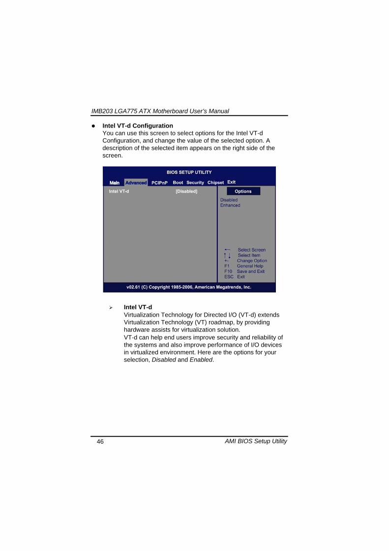
IMB203 LGA775 ATX Motherboard Userrsquos Manual
AMI BIOS Setup Utility 47
Remote Access Configuration You can use this screen to select options for the Remote Access Configuration and change the value of the selected option A description of the selected item appears on the right side of the screen
Remote Access Use this item to enable or disable the Remote Access function
IMB203 LGA775 ATX Motherboard Userrsquos Manual
AMI BIOS Setup Utility 48
PCI Express Configuration This screen shows the PCI Express Configuration and you can change its value A description of the selected item appears on the right side of the screen
Active State Power-Management
Use this item to enable or disable the function of Active State Power-Management to provide you with lower power consumption The default setting is Disabled
IMB203 LGA775 ATX Motherboard Userrsquos Manual
AMI BIOS Setup Utility 49
Trusted Computing You can use this screen to select options for the Trusted Computing and change the value of the selected option A description of the selected item appears on the right side of the screen
TCGTPM SUPPORT Use this item to control the Trusted Platform Module (TPM) function
IMB203 LGA775 ATX Motherboard Userrsquos Manual
AMI BIOS Setup Utility 50
USB Configuration You can use this screen to select options for the USB Configuration and change the value of the selected option A description of the selected item appears on the right side of the screen
USB Functions
This item allows you to enable or disable USB functions
Legacy USB Support Use this item to enable or disable support for USB device on legacy operating system The default setting is Enabled
USB 20 Controller Mode Use this item to configure the USB 20 controller The default setting is HiSpeed
BIOS EHCI Hand-Off Enabling this item provide the support for operating systems without an EHCI hand-off feature The default setting is Enabled
IMB203 LGA775 ATX Motherboard Userrsquos Manual
AMI BIOS Setup Utility 51
IMB203 LGA775 ATX Motherboard Userrsquos Manual
AMI BIOS Setup Utility 52
55 PCI PnP Menu The PCI PnP menu allows users to change the advanced settings for PCIPnP devices
Clear NVRAM
Use this item to clear the data in the NVRAM (CMOS) Here are the options for your selection No and Yes
Plug amp Play OS When the setting is No Use this item to configure all the devices in the system When the setting is Yes and if you install a Plug and Play operating system the operating system configures the Plug and Play devices not required for boot The default setting is No
IMB203 LGA775 ATX Motherboard Userrsquos Manual
AMI BIOS Setup Utility 53
PCI Latency Timer This item controls how long a PCI device can hold the PCI bus before another takes over The longer the latency the longer the PCI device can retain control of the bus before handing it over to another PCI device There are several options for your selection
Allocate IRQ to PCI VGA This item allows BIOS to choose an IRQ to assign for the PCI VGA card Here are the options for your selection No and Yes
Palette Snooping Some old graphic controllers need to ldquosnooprdquo on the VGA palette and then map it to their display as a way to provide boot information and VGA compatibility This item allows such snooping to take place Here are the options for your selection Disabled and Enabled
PCI IDE BusMaster This item is a toggle for the built-in driver that allows the onboard IDE controller to perform DMA (Direct Memory Access) transfer Here are the options for your selection Disabled and Enabled
OffBoard PCIISA IDE Card This item is for any other non-onboard PCIISA IDE controller adapter There are several options for your selection
IRQ3457910111415 These items will allow you to assign each system interrupt a type depending on the type of device using the interrupt The option ldquoAvailablerdquo means the IRQ is going to assign automatically Here are the options for your selection Available and Reserved
DMA Channel 013567 These items will allow you to assign each DMA channel a type depending on the type of device using the channel The option ldquoAvailablerdquo means the channel is going to assign automatically Here are the options for your selection Available and Reserved
IMB203 LGA775 ATX Motherboard Userrsquos Manual
AMI BIOS Setup Utility 54
56 Boot Menu The Boot menu allows users to change boot options of the system You can select any of the items in the left frame of the screen to go to the sub menus
Boot Settings Configuration Boot Device Priority Removable Drives
For items marked with ldquo rdquo please press ltEntergt for more options
IMB203 LGA775 ATX Motherboard Userrsquos Manual
AMI BIOS Setup Utility 55
Boot Settings Configuration
Quick Boot
Enabling this item lets the BIOS skip some power on self tests (POST) The default setting is Enabled
AddOn ROM Display Mode This item selects the display mode for option ROM The default setting is Force BIOS
Boot Num-Lock Use this item to select the power-on state for the NumLock The default setting is On
PS2 Mouse Support This item determines if the BIOS should reserve IRQ12 for the PS2 mouse or allow other devices to make use of this IRQ Here are the options for your selection Auto Enabled and Disabled
Wait For lsquoF1rsquo Of Error If this item is enabled the system waits for the F1 key to be pressed when error occurs The default setting is Enabled
Hit lsquoDELrsquo Message Display If this item is enabled the system displays the message
IMB203 LGA775 ATX Motherboard Userrsquos Manual
AMI BIOS Setup Utility 56
ldquoPress DEL to run Setuprdquo during POST The default setting is Enabled
Interrupt 19 Capture If this item is enabled this function makes the option ROMs to trap Interrupt 19 The default setting is Disabled
Boot Device Priority The Boot Device Priority screen specifies the boot device priority sequence from the available devices
IMB203 LGA775 ATX Motherboard Userrsquos Manual
AMI BIOS Setup Utility 57
Removable Drives Use this screen to view the removable drives in the system The BIOS will attempt to arrange the removable drive boot sequence automatically You can also change the booting sequence
IMB203 LGA775 ATX Motherboard Userrsquos Manual
AMI BIOS Setup Utility 58
57 Security Menu The Security menu allows users to change the security settings for the system
Supervisor Password
This item indicates whether a supervisor password has been set If the password has been installed Installed displays If not Not Installed displays
User Password This item indicates whether a user password has been set If the password has been installed Installed displays If not Not Installed displays
Change Supervisor Password Select this option and press ltEntergt to access the sub menu You can use the sub menu to change the supervisor password
Change User Password Select this option and press ltEntergt to access the sub menu You can use the sub menu to change the user password
IMB203 LGA775 ATX Motherboard Userrsquos Manual
AMI BIOS Setup Utility 59
58 Chipset Menu The Chipset menu allows users to change the advanced chipset settings You can select any of the items in the left frame of the screen to go to the sub menus
North Bridge Configuration South Bridge Configuration ME Subsystem Configuration
For items marked with ldquo rdquo please press ltEntergt for more options
IMB203 LGA775 ATX Motherboard Userrsquos Manual
AMI BIOS Setup Utility 60
North Bridge Configuration
Memory Remap Feature
Use this item to enable or disable the remapping of the overlapped PCI memory above the total physical memory Only 64-bit OS supports this function
DRAM Frequency This item allows you to control the Memory Clock
Configure DRAM Timing by SPD This item can enable or disable DRAM timing by SPD (Serial Presence Detect) device which is a small EEPROM chip on the memory module containing important information about the module speed size addressing mode and various parameters
Memory Hole You can reserve this area of system memory for ISA adapter ROM When this area is reserved it cannot be cached Check the user information of peripherals that need to use this area o f system memory for the memory requirements Here are the options Disabled and 15M-16M
IMB203 LGA775 ATX Motherboard Userrsquos Manual
AMI BIOS Setup Utility 61
Initiate Graphic Adapter When using multiple graphics cards this item can select which graphics controller to be the primary display device during boot
IGD Graphics Mode Select This item allows you to select the amount of system memory used by the internal graphics device
PEG Port ConfigurationPEG Port This item is a toggle to enable or disable the PCI Express port Here are the options for your selection Auto and Disabled
Video Function Configuration Press ltEntergt for the sub-menu for setting up video function
IMB203 LGA775 ATX Motherboard Userrsquos Manual
AMI BIOS Setup Utility 62
South Bridge Configuration
GbE Wake Up From S5 This item specifies whether the system will be awakened from the S5 power
HDA Controller This item allows you to enable or disable the HD audio support
Restore on AC Power Loss This item can control how the PC will behave once power is restored following a power outage or other unexpected shutdown
PCIE Port Configuration This item allows you to set or disable the PCI Express Ports
IMB203 LGA775 ATX Motherboard Userrsquos Manual
AMI BIOS Setup Utility 63
ME Subsystem Configuration
It is strongly recommended that you do not modify these options unless you are an advanced user
IMB203 LGA775 ATX Motherboard Userrsquos Manual
AMI BIOS Setup Utility 64
59 Exit Menu The Exit menu allows users to load your system configuration with optimal or failsafe default values
Save Changes and Exit
When you have completed the system configuration changes select this option to leave Setup and reboot the computer so the new system configuration parameters can take effect Select Save Changes and Exit from the Exit menu and press ltEntergt Select Ok to save changes and exit
Discard Changes and Exit Select this option to quit Setup without making any permanent changes to the system configuration Select Discard Changes and Exit from the Exit menu and press ltEntergt Select Ok to discard changes and exit
Load Optimal Defaults It automatically sets all Setup options to a complete set of default settings when you select this option The Optimal settings are designed for maximum system performance but may not work best for all computer applications In particular do not use the Optimal Setup options if your
IMB203 LGA775 ATX Motherboard Userrsquos Manual
AMI BIOS Setup Utility 65
computer is experiencing system configuration problems Select Load Optimal Defaults from the Exit menu and press ltEntergt
Load Fail-Safe Defaults It automatically sets all Setup options to a complete set of default settings when you select this option The Fail-Safe settings are designed for maximum system stability but not maximum performance Select the Fail-Safe Setup options if your computer is experiencing system configuration problems Select Load Fail-Safe Defaults from the Exit menu and press ltEntergt Select Ok to load Fail-Safe defaults
IMB203 LGA775 ATX Motherboard Userrsquos Manual
AMI BIOS Setup Utility 66
MEMO
IMB203 LGA775 ATX Motherboard Userrsquos Manual
Installation of Drivers 67
CHPATER 6 INSTALLATION OF DRIVERS
The device drivers are located on the Product Information CD-ROM that comes with the IMB203 Series package The auto-run function of drivers will guide you to install the utilities and device drivers under a Windows system You can follow the onscreen instructions to install these devices
Chipse VGA LAN Audio iAMT MEI
61 Installing Chipset Driver 1 Run the SETUPEXE program from the driver directory in
your driver CD Click ldquoNextrdquo to next step
IMB203 LGA775 ATX Motherboard Userrsquos Manual
Installation of Drivers 68
2 An Intelreg License Agreement appears to show you the important information Click ldquoYesrdquo to next step
3 Refer to the Readme file below to view the system requirements and installation information
IMB203 LGA775 ATX Motherboard Userrsquos Manual
Installation of Drivers 69
3-1 Please wait while running the following setup operations
3-2 Please wait while running the following setup operations
IMB203 LGA775 ATX Motherboard Userrsquos Manual
Installation of Drivers 70
4 Click ldquoFinishrdquo to complete the setup process
5 You will be asked to reboot your computer when the installation is completed Please click ldquoYes I want to restart my computer nowrdquo if you donrsquot need to install any other drivers Otherwise please click ldquoNo I will restart my computer laterrdquo and go on next step
IMB203 LGA775 ATX Motherboard Userrsquos Manual
Installation of Drivers 71
62 Installing VGA Driver 1 Run the SETUPEXE program from the driver directory in
your driver CD Click ldquoNextrdquo to next step
2 An Intelreg License Agreement appears to show you the
important information Click ldquoYesrdquo to next step
IMB203 LGA775 ATX Motherboard Userrsquos Manual
Installation of Drivers 72
3 The message of Readme File Information appears to show you the system requirements and installation information Please click ldquoNextrdquo
4 Please wait while running the following setup operations
When this message appears please click ldquoNextrdquo
IMB203 LGA775 ATX Motherboard Userrsquos Manual
Installation of Drivers 73
5 Click ldquoFinishrdquo to complete the setup process
6 You will be asked to reboot your computer when the installation is completed Please click ldquoYes I want to restart my computer nowrdquo if you donrsquot need to install any other drivers Otherwise please click ldquoNo I will restart my computer laterrdquo and click ldquoFinishrdquo to complete the installation
IMB203 LGA775 ATX Motherboard Userrsquos Manual
Installation of Drivers 74
63 Installing LAN Driver
11 Run the InstallShield Wizard for Network Connections from
the driver directory in your driver CD Click ldquoNextrdquo to next step
IMB203 LGA775 ATX Motherboard Userrsquos Manual
Installation of Drivers 75
12 An Intelreg License Agreement appears to show you the important information Click ldquoYesrdquo to next step
13 A Setup Options window appears that you can select the
program features you want to install
IMB203 LGA775 ATX Motherboard Userrsquos Manual
Installation of Drivers 76
2 Click ldquoInstallrdquo to start the installation
3 Please wait while running the following installation operation
IMB203 LGA775 ATX Motherboard Userrsquos Manual
Installation of Drivers 77
4 Click ldquoFinishrdquo to complete the installation
Note The Driver item [Wake on Directed Packet] default is Enabled under Windows Vista
格式化 字型 (符號) Arial
格式化 字型 (符號) Arial
格式化 字型 斜體 字型色彩 黑色 (符號) Arial 非加寬 緊縮
格式化 字型 斜體 字型色彩 黑色 (符號) Arial 非加寬 緊縮
格式化 字型 (符號) Arial 非加寬 緊縮
IMB203 LGA775 ATX Motherboard Userrsquos Manual
Installation of Drivers 78
64 Installing AUDIO Driver 1 Run the InstallShield Wizard for Realtek High Definition
Audio Driver from the driver directory in your driver CD Click ldquoNextrdquo to next step
IMB203 LGA775 ATX Motherboard Userrsquos Manual
Installation of Drivers 79
2 Click ldquoInstallrdquo to start the installation and wait while running the installation operation
3 Click ldquoFinishrdquo to complete the installation
IMB203 LGA775 ATX Motherboard Userrsquos Manual
Installation of Drivers 80
65 Installing iAMT (Active Management Technology) Driver
Note You must download and properly install the required NET version 35 provided from a separate downloading of the actual FimwareTools kit releases posted on VIP prior to loading the MEILMS Driver stack
651 LMS_SOL Setup
1 Run the setup program to install Intelreg Active Management Technology onto your computer It is strongly recommended that you exit all programs before continuing Click ldquoNextrdquo to next step
格式化 字型 (符號) Arial
格式化 字型 (符號) Arial 非加寬 緊縮
IMB203 LGA775 ATX Motherboard Userrsquos Manual
Installation of Drivers 81
2 An Intelreg license agreement appears that you need to continue the setup program by clicking ldquoYesrdquo to accept the terms
IMB203 LGA775 ATX Motherboard Userrsquos Manual
Installation of Drivers 82
3 Refer to the Readme file below to view the system requirements and installation information Click ldquoNextrdquo to next setup
4 Please wait while running the following installation operation
IMB203 LGA775 ATX Motherboard Userrsquos Manual
Installation of Drivers 83
5 Click ldquoFinishrdquo to complete the installation
IMB203 LGA775 ATX Motherboard Userrsquos Manual
Installation of Drivers 84
652 LMS_SOL_IS Setup
1 Run the setup program to install Intelreg Active Management Technology onto your computer It is strongly recommended that you exit all programs before continuing Click ldquoNextrdquo to next step
IMB203 LGA775 ATX Motherboard Userrsquos Manual
Installation of Drivers 85
2 An Intelreg license agreement appears that you need to continue the setup program by clicking ldquoYesrdquo to accept the terms
IMB203 LGA775 ATX Motherboard Userrsquos Manual
Installation of Drivers 86
3 Refer to the Readme file below to view the system requirements and installation information Click ldquoNextrdquo to next setup
4 Please wait while running the following installation operation
IMB203 LGA775 ATX Motherboard Userrsquos Manual
Installation of Drivers 87
5 Click ldquoFinishrdquo to complete the installation
IMB203 LGA775 ATX Motherboard Userrsquos Manual
Installation of Drivers 88
66 Installing MEI (Management Engine Interface) Driver
Note You must download and properly install the required NET version 35 provided from a separate downloading of the actual FimwareTools kit releases posted on VIP prior to loading the MEILMS Driver stack
1 Run the setup program to install Intelreg Management Engine
Interface onto your computer It is strongly recommended that you exit all programs before continuing Click ldquoNextrdquo to next step
格式化 字型 (符號) Arial
格式化 字型 (符號) Arial 非加寬 緊縮
IMB203 LGA775 ATX Motherboard Userrsquos Manual
Installation of Drivers 89
2 An Intelreg license agreement appears that you need to continue the setup program by clicking ldquoYesrdquo to accept the terms
IMB203 LGA775 ATX Motherboard Userrsquos Manual
Installation of Drivers 90
3 Refer to the Readme file below to view the system requirements and installation information Click ldquoNextrdquo to next setup
4 Please wait while running the following installation operation
IMB203 LGA775 ATX Motherboard Userrsquos Manual
Installation of Drivers 91
5 Click ldquoFinishrdquo to complete the installation
IMB203 LGA775 ATX Motherboard Userrsquos Manual
Installation of Drivers 92
MEMO
IMB203 LGA775 ATX Motherboard Userrsquos Manual
Watchdog Timer 93
APPENDIX A WATCHDOG TIMER
Watchdog Timer Setting After the system stops working for a while it can be auto-reset by the Watchdog Timer The integrated Watchdog Timer can be set up in the system reset mode by program
Using the Watchdog Function Start darr Un-Lock WDT O 2E 87 Un-lock super IO
O 2E 87 Un-lock super IO darr Set WDT Function O 2E 2D O 2F 20 Select Logic device O 2E 07 O 2F 08 darr Activate WDT O 2E 30
O 2F 01 Set Second or Minute O 2E F5
O 2F N N=00 or 08(See below table) darr Set base timer O 2E F6
O 2F M=000102hellipFF(Hex) Value=0 to 255 darr WDT counting
re-set timer O 2E F6
O 2F M M=000102hellipFF(See below table) darr
格式化
格式化 項目符號及編號
格式化 項目符號及編號
格式化 字型 8 點 字型色彩黑色
格式化 字型 8 點 字型色彩黑色
格式化 定位點 1257 字元左 + 不在 1012 字元 + 1386字元
格式化 字型 8 點 字型色彩黑色
格式化 定位點 1257 字元左 + 不在 134 字元 + 1362字元
格式化 字型色彩 黑色
格式化 字型色彩 黑色
刪除
IMB203 LGA775 ATX Motherboard Userrsquos Manual
Watchdog Timer 94
IF No re-set timer WDT time-out generate RESET IF to disable WDT O 2E 30
O 2F 00 Can be disable at any time
N=00
M= 00h Time-out Disable 01h Time-out occurs after 1 second 02h Time-out occurs after 2 second 03h Time-out occurs after 3 second helliphelliphelliphelliphelliphelliphelliphelliphellip FFh Time-out occurs after 255 second
N=08
M= 00h Time-out Disable 01h Time-out occurs after 1 minute 02h Time-out occurs after 2 minutes 03h Time-out occurs after 3 minutes helliphelliphelliphelliphelliphelliphelliphelliphellip
FFh Time-out occurs after 255 minutes
格式化 字型色彩 黑色
格式化 字型色彩 黑色
IMB203 LGA775 ATX Motherboard Userrsquos Manual
PCI IRQ Routing 95
APPENDIX B PCI IRQ ROUTING
PICMG PCI IRQ Routing
Device ID Slot Int
PCI Slot 0 31 0 BCDA PCI Slot 1 30 1 CDAB PCI Slot 2 29 2 DABC PCI Slot 3 28 3 ABCD
IMB203 LGA775 ATX Motherboard Userrsquos Manual
PCI IRQ Routing 96
MEMO
IMB203 LGA775 ATX Motherboard Userrsquos Manual
Configuring SATA for RAID Function 97
APPENDIX C CONFIGURING SATA FOR RAID
FUNCTION
Configuring SATA Hard Drive(s) for RAID Function (Controller IntelregICH10DODO DH only) Please follow up the steps below to configure SATA hard drive(s) (1) Install SATA hard drive(s) in your system (2) Enter the BIOS Setup to configure SATA controller mode and boot
sequence (3) Configure RAID by the RAID BIOS (4) Install the SATA controller driver during the OS installation Before you begin the SATA configuration please prepare (a) Two SATA hard drives (to ensure optimal performance it is
recommended that you use two hard drives with identical model and capacity) If you do not want to create RAID with the SATA controller you may prepare only one hard drive
(b) An empty formatted floppy disk (c) Windows XP setup disk (1) Installing SATA hard drive(s) in your system
Connect one end of the SATA signal cable to the rear of the SATA hard drive and the other end to available SATA port(s) on the board Then connect the power connector of power supply to the hard drive
(2) Configuring SATA controller mode and boot sequence by the BIOS Setup You have to make sure whether the SATA controller is configured correctly by system BIOS Setup and set up BIOS boot sequence for the SATA hard drive(s)
IMB203 LGA775 ATX Motherboard Userrsquos Manual
Configuring SATA for RAID Function 98
(2)-1-1 Turn on your system and then press the Del button to enter BIOS Setup during running POST (Power-On Self Test) If you want to create RAID just go to the Advanced Settings menuIDE configuration select the Configure SATA1 as and press ltEntergt for more options
IMB203 LGA775 ATX Motherboard Userrsquos Manual
Configuring SATA for RAID Function 99
(2)-1-2 A list of options appears please select RAID
IMB203 LGA775 ATX Motherboard Userrsquos Manual
Configuring SATA for RAID Function 100
(2)-2 Set CDROM for First Boot Device under the Boot Settings menu to boot CD-ROM after system restarts
(2)-3 Save and exit the BIOS Setup
IMB203 LGA775 ATX Motherboard Userrsquos Manual
Configuring SATA for RAID Function 101
(3) Configuring RAID by the RAID BIOS Enter the RAID BIOS setup utility to configure a RAID array Skip this step and proceed to Section 4 if you do not want to create a RAID (3)-1 After the POST memory testing and before the operating
system booting a message Press ltCtrl-Igt to enter Configuration Utility shows up accordingly press ltCTRL+ Igt to enter the RAID BIOS setup utility
(3)-2 After you press ltCTRL+ Igt the Create RAID Volume screen will appear If you want to create a RAID array select the Create RAID Volume option in the Main Menu and press ENTER
IMB203 LGA775 ATX Motherboard Userrsquos Manual
Configuring SATA for RAID Function 102
(3)-3-1 After entering the CREATE VOLUME MENU screen you can type the disk array name with 1~16 letters (letters cannot be special characters) in the item ldquoNamerdquo
(3)-3-2 When finished press ENTER to select a RAID level There are three RAID levels RAID0 RAID1 and RAID5 amp RAID10 Select a RAID level and press ENTER
IMB203 LGA775 ATX Motherboard Userrsquos Manual
Configuring SATA for RAID Function 103
(3)-4 Set the stripe block size The KB is the standard unit of stripe block size The stripe block size can be 4KB to 128KB After the setting press ENTER for the array capacity
(3)-5 After setting all the items on the menu select Create Volume
and press ENTER to start creating the RAID array
IMB203 LGA775 ATX Motherboard Userrsquos Manual
Configuring SATA for RAID Function 104
(3)-6 When prompting the confirmation press ldquoYldquo to create this volume or ldquoNldquo to cancel the creation
After the creation is completed you can see detailed information about the RAID Array in the DISKVOLUME INFORMATION section including RAID mode disk block size disk name and disk capacity etc
IMB203 LGA775 ATX Motherboard Userrsquos Manual
Configuring SATA for RAID Function 105
Delete RAID Volume If you want to delete a RAID volume select the Delete RAID Volume option in Main Menu Press ENTER and follow on-screen instructions
Please press [ESC] to exit the RAID BIOS utility Now you can proceed to install a SATA driver controller and the operating system
IMB203 LGA775 ATX Motherboard Userrsquos Manual
Configuring SATA for RAID Function 106
(4) Making a SATA Driver Disk To install the operating system onto a serial ATA hard disk successfully you need to install the SATA controller driver during the OS installation Without the driver the hard disk may not be recognized during the Windows setup process First of all please format a blank floppy disk Secondly follow up these steps below to produce a SATA driver disk Users can insert the Driver CD and the formatted blank floppy disk in another system And then please copy all of file of the f6flpy32 folder in the Driver CD to a floppy disk Note Please copy all of file of the f6flpy64 folder if installing 64-bit
Windows Operating System
IMB203 LGA775 ATX Motherboard Userrsquos Manual
Configuring SATA for RAID Function 107
(5) Installing the SATA controller driver during the OS installation Now the SATA driver disk is ready and BIOS settings configured you can proceed to install Windows 2000XP onto your SATA hard drive using the SATA driver Here is an example for Windows XP installation (5)-1 Restart your system to boot the Windows 2000XP Setup disk
and press F6 button as soon as you see the message Press F6 if you need to install a 3rd party SCSI or RAID driver After pressing the F6 button there will be a few moments for some files being loaded before next screen appears
IMB203 LGA775 ATX Motherboard Userrsquos Manual
Configuring SATA for RAID Function 108
(5)-2 When you see the screen below insert the floppy disk containing the SATA driver and press ldquoSrdquo
(5)-3 If the Setup correctly recognizes the driver of the floppy disk
a controller menu will appear below Use the ARROW keys to select Intel(R) ICH8RICH9RICH10RDO SATA RAID Controller and press ENTER Then it will begin to load the SATA driver from the floppy disk
IMB203 LGA775 ATX Motherboard Userrsquos Manual
Configuring SATA for RAID Function 109
Note If a message on the screen saying that one or some file(s) cannot be found please check the floppy disk or copy the correct SATA driver again from the driver CD
IMB203 LGA775 ATX Motherboard Userrsquos Manual
Configuring SATA for RAID Function 110
MEMO
IMB203 LGA775 ATX Motherboard Userrsquos Manual
iAMT Settings 111
APPENDIX D iAMT SETTINGS
The Intelreg Active Management Technology (Intelreg iAMT) has decreased a major barrier to IT efficiency that uses built-in platform capabilities and popular third-party management and security applications to allow IT a better discovering healing and protection their networked computing assets In order to utilize Intel iAMT you must enter the ME BIOS (CTRL + P during system startup) change the ME BIOS password and then select ldquoIntelreg iAMTrdquo as the manageability feature
D1 Entering MEBx 1 You must go to BIOS TO start iAMT function 2 Exit from BIOS after starting iAMT and press Ctrl+P to enter MEBx Setting
It is better to press Ctrl+P before the screen popping out
格式化
IMB203 LGA775 ATX Motherboard Userrsquos Manual
iAMT Settings 112
D2 Set amp Change Password 1 You will be asked to set a password when first log in The default
password is lsquoadminrsquo
2 You will be asked to change the password before setting ME
Change Password
IMB203 LGA775 ATX Motherboard Userrsquos Manual
iAMT Settings 113
3 You must confirm your new password while revising (as Remark 1)
Remark 1 The new password must contain (example 11qqQQ) (default value)
Eight characters
One upper case
One lower case
One number
One special symbol such as $ or
( excepted)
Underline ( _ ) and space are valid characters for password but they wonrsquot make higher complexity
IMB203 LGA775 ATX Motherboard Userrsquos Manual
iAMT Settings 114
D3 Intelreg iAMT Settings 1 Select Intelreg iAMT Configuration and press ltENTERgt
2 Key in the Host Name If Intelreg iAMT set to lsquoDHCPlsquo the Host name must be identical to the operating system mechanic
IMB203 LGA775 ATX Motherboard Userrsquos Manual
iAMT Settings 115
3 Select TCPIP to get into Network interface and set it to lsquoENABLEDrsquo into DHCP Mode and set it to lsquoDISABLEDrsquo (as Remark 2) into Domain name and set the Intel Management Engine domain name such as lsquoAMTintelcomrsquo
(3-1)
(3-2)
IMB203 LGA775 ATX Motherboard Userrsquos Manual
iAMT Settings 116
Remark 2 DHCP Mode lsquoDISABLEDlsquo if DHCP Mode is disabled you can make the following settings
IP address
Subnet mask
IMB203 LGA775 ATX Motherboard Userrsquos Manual
iAMT Settings 117
Default Gateway address
Preferred DNS address
IMB203 LGA775 ATX Motherboard Userrsquos Manual
iAMT Settings 118
Alternate DNS address
Domain name
4 Exit from MEBx after completing the iAMT settings
IMB203 LGA775 ATX Motherboard Userrsquos Manual
iAMT Settings 119
D4 iAMT Web Console 1 From a web browser please type http(IP ADDRESS)16992
which connects to iAMT Web Example http1014021416992
2 To log on you will be required to type in username and password
for access to the Web
USER admin (default value)
PASS (MEBx password)
IMB203 LGA775 ATX Motherboard Userrsquos Manual
iAMT Settings 120
3 Enter the iAMT Web
4 Click Remote Control and select commands on the right side
IMB203 LGA775 ATX Motherboard Userrsquos Manual
iAMT Settings 121
5 When you have finished using the iAMT Web console close the Web browser
IMB203 LGA775 ATX Motherboard Userrsquos Manual
iAMT Settings 122
MEMO
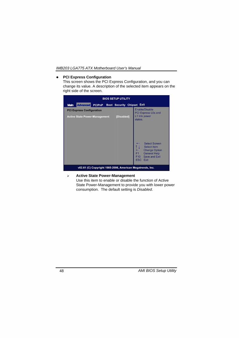
IMB203 LGA775 ATX Motherboard Userrsquos Manual
AMI BIOS Setup Utility 48
PCI Express Configuration This screen shows the PCI Express Configuration and you can change its value A description of the selected item appears on the right side of the screen
Active State Power-Management
Use this item to enable or disable the function of Active State Power-Management to provide you with lower power consumption The default setting is Disabled
IMB203 LGA775 ATX Motherboard Userrsquos Manual
AMI BIOS Setup Utility 49
Trusted Computing You can use this screen to select options for the Trusted Computing and change the value of the selected option A description of the selected item appears on the right side of the screen
TCGTPM SUPPORT Use this item to control the Trusted Platform Module (TPM) function
IMB203 LGA775 ATX Motherboard Userrsquos Manual
AMI BIOS Setup Utility 50
USB Configuration You can use this screen to select options for the USB Configuration and change the value of the selected option A description of the selected item appears on the right side of the screen
USB Functions
This item allows you to enable or disable USB functions
Legacy USB Support Use this item to enable or disable support for USB device on legacy operating system The default setting is Enabled
USB 20 Controller Mode Use this item to configure the USB 20 controller The default setting is HiSpeed
BIOS EHCI Hand-Off Enabling this item provide the support for operating systems without an EHCI hand-off feature The default setting is Enabled
IMB203 LGA775 ATX Motherboard Userrsquos Manual
AMI BIOS Setup Utility 51
IMB203 LGA775 ATX Motherboard Userrsquos Manual
AMI BIOS Setup Utility 52
55 PCI PnP Menu The PCI PnP menu allows users to change the advanced settings for PCIPnP devices
Clear NVRAM
Use this item to clear the data in the NVRAM (CMOS) Here are the options for your selection No and Yes
Plug amp Play OS When the setting is No Use this item to configure all the devices in the system When the setting is Yes and if you install a Plug and Play operating system the operating system configures the Plug and Play devices not required for boot The default setting is No
IMB203 LGA775 ATX Motherboard Userrsquos Manual
AMI BIOS Setup Utility 53
PCI Latency Timer This item controls how long a PCI device can hold the PCI bus before another takes over The longer the latency the longer the PCI device can retain control of the bus before handing it over to another PCI device There are several options for your selection
Allocate IRQ to PCI VGA This item allows BIOS to choose an IRQ to assign for the PCI VGA card Here are the options for your selection No and Yes
Palette Snooping Some old graphic controllers need to ldquosnooprdquo on the VGA palette and then map it to their display as a way to provide boot information and VGA compatibility This item allows such snooping to take place Here are the options for your selection Disabled and Enabled
PCI IDE BusMaster This item is a toggle for the built-in driver that allows the onboard IDE controller to perform DMA (Direct Memory Access) transfer Here are the options for your selection Disabled and Enabled
OffBoard PCIISA IDE Card This item is for any other non-onboard PCIISA IDE controller adapter There are several options for your selection
IRQ3457910111415 These items will allow you to assign each system interrupt a type depending on the type of device using the interrupt The option ldquoAvailablerdquo means the IRQ is going to assign automatically Here are the options for your selection Available and Reserved
DMA Channel 013567 These items will allow you to assign each DMA channel a type depending on the type of device using the channel The option ldquoAvailablerdquo means the channel is going to assign automatically Here are the options for your selection Available and Reserved
IMB203 LGA775 ATX Motherboard Userrsquos Manual
AMI BIOS Setup Utility 54
56 Boot Menu The Boot menu allows users to change boot options of the system You can select any of the items in the left frame of the screen to go to the sub menus
Boot Settings Configuration Boot Device Priority Removable Drives
For items marked with ldquo rdquo please press ltEntergt for more options
IMB203 LGA775 ATX Motherboard Userrsquos Manual
AMI BIOS Setup Utility 55
Boot Settings Configuration
Quick Boot
Enabling this item lets the BIOS skip some power on self tests (POST) The default setting is Enabled
AddOn ROM Display Mode This item selects the display mode for option ROM The default setting is Force BIOS
Boot Num-Lock Use this item to select the power-on state for the NumLock The default setting is On
PS2 Mouse Support This item determines if the BIOS should reserve IRQ12 for the PS2 mouse or allow other devices to make use of this IRQ Here are the options for your selection Auto Enabled and Disabled
Wait For lsquoF1rsquo Of Error If this item is enabled the system waits for the F1 key to be pressed when error occurs The default setting is Enabled
Hit lsquoDELrsquo Message Display If this item is enabled the system displays the message
IMB203 LGA775 ATX Motherboard Userrsquos Manual
AMI BIOS Setup Utility 56
ldquoPress DEL to run Setuprdquo during POST The default setting is Enabled
Interrupt 19 Capture If this item is enabled this function makes the option ROMs to trap Interrupt 19 The default setting is Disabled
Boot Device Priority The Boot Device Priority screen specifies the boot device priority sequence from the available devices
IMB203 LGA775 ATX Motherboard Userrsquos Manual
AMI BIOS Setup Utility 57
Removable Drives Use this screen to view the removable drives in the system The BIOS will attempt to arrange the removable drive boot sequence automatically You can also change the booting sequence
IMB203 LGA775 ATX Motherboard Userrsquos Manual
AMI BIOS Setup Utility 58
57 Security Menu The Security menu allows users to change the security settings for the system
Supervisor Password
This item indicates whether a supervisor password has been set If the password has been installed Installed displays If not Not Installed displays
User Password This item indicates whether a user password has been set If the password has been installed Installed displays If not Not Installed displays
Change Supervisor Password Select this option and press ltEntergt to access the sub menu You can use the sub menu to change the supervisor password
Change User Password Select this option and press ltEntergt to access the sub menu You can use the sub menu to change the user password
IMB203 LGA775 ATX Motherboard Userrsquos Manual
AMI BIOS Setup Utility 59
58 Chipset Menu The Chipset menu allows users to change the advanced chipset settings You can select any of the items in the left frame of the screen to go to the sub menus
North Bridge Configuration South Bridge Configuration ME Subsystem Configuration
For items marked with ldquo rdquo please press ltEntergt for more options
IMB203 LGA775 ATX Motherboard Userrsquos Manual
AMI BIOS Setup Utility 60
North Bridge Configuration
Memory Remap Feature
Use this item to enable or disable the remapping of the overlapped PCI memory above the total physical memory Only 64-bit OS supports this function
DRAM Frequency This item allows you to control the Memory Clock
Configure DRAM Timing by SPD This item can enable or disable DRAM timing by SPD (Serial Presence Detect) device which is a small EEPROM chip on the memory module containing important information about the module speed size addressing mode and various parameters
Memory Hole You can reserve this area of system memory for ISA adapter ROM When this area is reserved it cannot be cached Check the user information of peripherals that need to use this area o f system memory for the memory requirements Here are the options Disabled and 15M-16M
IMB203 LGA775 ATX Motherboard Userrsquos Manual
AMI BIOS Setup Utility 61
Initiate Graphic Adapter When using multiple graphics cards this item can select which graphics controller to be the primary display device during boot
IGD Graphics Mode Select This item allows you to select the amount of system memory used by the internal graphics device
PEG Port ConfigurationPEG Port This item is a toggle to enable or disable the PCI Express port Here are the options for your selection Auto and Disabled
Video Function Configuration Press ltEntergt for the sub-menu for setting up video function
IMB203 LGA775 ATX Motherboard Userrsquos Manual
AMI BIOS Setup Utility 62
South Bridge Configuration
GbE Wake Up From S5 This item specifies whether the system will be awakened from the S5 power
HDA Controller This item allows you to enable or disable the HD audio support
Restore on AC Power Loss This item can control how the PC will behave once power is restored following a power outage or other unexpected shutdown
PCIE Port Configuration This item allows you to set or disable the PCI Express Ports
IMB203 LGA775 ATX Motherboard Userrsquos Manual
AMI BIOS Setup Utility 63
ME Subsystem Configuration
It is strongly recommended that you do not modify these options unless you are an advanced user
IMB203 LGA775 ATX Motherboard Userrsquos Manual
AMI BIOS Setup Utility 64
59 Exit Menu The Exit menu allows users to load your system configuration with optimal or failsafe default values
Save Changes and Exit
When you have completed the system configuration changes select this option to leave Setup and reboot the computer so the new system configuration parameters can take effect Select Save Changes and Exit from the Exit menu and press ltEntergt Select Ok to save changes and exit
Discard Changes and Exit Select this option to quit Setup without making any permanent changes to the system configuration Select Discard Changes and Exit from the Exit menu and press ltEntergt Select Ok to discard changes and exit
Load Optimal Defaults It automatically sets all Setup options to a complete set of default settings when you select this option The Optimal settings are designed for maximum system performance but may not work best for all computer applications In particular do not use the Optimal Setup options if your
IMB203 LGA775 ATX Motherboard Userrsquos Manual
AMI BIOS Setup Utility 65
computer is experiencing system configuration problems Select Load Optimal Defaults from the Exit menu and press ltEntergt
Load Fail-Safe Defaults It automatically sets all Setup options to a complete set of default settings when you select this option The Fail-Safe settings are designed for maximum system stability but not maximum performance Select the Fail-Safe Setup options if your computer is experiencing system configuration problems Select Load Fail-Safe Defaults from the Exit menu and press ltEntergt Select Ok to load Fail-Safe defaults
IMB203 LGA775 ATX Motherboard Userrsquos Manual
AMI BIOS Setup Utility 66
MEMO
IMB203 LGA775 ATX Motherboard Userrsquos Manual
Installation of Drivers 67
CHPATER 6 INSTALLATION OF DRIVERS
The device drivers are located on the Product Information CD-ROM that comes with the IMB203 Series package The auto-run function of drivers will guide you to install the utilities and device drivers under a Windows system You can follow the onscreen instructions to install these devices
Chipse VGA LAN Audio iAMT MEI
61 Installing Chipset Driver 1 Run the SETUPEXE program from the driver directory in
your driver CD Click ldquoNextrdquo to next step
IMB203 LGA775 ATX Motherboard Userrsquos Manual
Installation of Drivers 68
2 An Intelreg License Agreement appears to show you the important information Click ldquoYesrdquo to next step
3 Refer to the Readme file below to view the system requirements and installation information
IMB203 LGA775 ATX Motherboard Userrsquos Manual
Installation of Drivers 69
3-1 Please wait while running the following setup operations
3-2 Please wait while running the following setup operations
IMB203 LGA775 ATX Motherboard Userrsquos Manual
Installation of Drivers 70
4 Click ldquoFinishrdquo to complete the setup process
5 You will be asked to reboot your computer when the installation is completed Please click ldquoYes I want to restart my computer nowrdquo if you donrsquot need to install any other drivers Otherwise please click ldquoNo I will restart my computer laterrdquo and go on next step
IMB203 LGA775 ATX Motherboard Userrsquos Manual
Installation of Drivers 71
62 Installing VGA Driver 1 Run the SETUPEXE program from the driver directory in
your driver CD Click ldquoNextrdquo to next step
2 An Intelreg License Agreement appears to show you the
important information Click ldquoYesrdquo to next step
IMB203 LGA775 ATX Motherboard Userrsquos Manual
Installation of Drivers 72
3 The message of Readme File Information appears to show you the system requirements and installation information Please click ldquoNextrdquo
4 Please wait while running the following setup operations
When this message appears please click ldquoNextrdquo
IMB203 LGA775 ATX Motherboard Userrsquos Manual
Installation of Drivers 73
5 Click ldquoFinishrdquo to complete the setup process
6 You will be asked to reboot your computer when the installation is completed Please click ldquoYes I want to restart my computer nowrdquo if you donrsquot need to install any other drivers Otherwise please click ldquoNo I will restart my computer laterrdquo and click ldquoFinishrdquo to complete the installation
IMB203 LGA775 ATX Motherboard Userrsquos Manual
Installation of Drivers 74
63 Installing LAN Driver
11 Run the InstallShield Wizard for Network Connections from
the driver directory in your driver CD Click ldquoNextrdquo to next step
IMB203 LGA775 ATX Motherboard Userrsquos Manual
Installation of Drivers 75
12 An Intelreg License Agreement appears to show you the important information Click ldquoYesrdquo to next step
13 A Setup Options window appears that you can select the
program features you want to install
IMB203 LGA775 ATX Motherboard Userrsquos Manual
Installation of Drivers 76
2 Click ldquoInstallrdquo to start the installation
3 Please wait while running the following installation operation
IMB203 LGA775 ATX Motherboard Userrsquos Manual
Installation of Drivers 77
4 Click ldquoFinishrdquo to complete the installation
Note The Driver item [Wake on Directed Packet] default is Enabled under Windows Vista
格式化 字型 (符號) Arial
格式化 字型 (符號) Arial
格式化 字型 斜體 字型色彩 黑色 (符號) Arial 非加寬 緊縮
格式化 字型 斜體 字型色彩 黑色 (符號) Arial 非加寬 緊縮
格式化 字型 (符號) Arial 非加寬 緊縮
IMB203 LGA775 ATX Motherboard Userrsquos Manual
Installation of Drivers 78
64 Installing AUDIO Driver 1 Run the InstallShield Wizard for Realtek High Definition
Audio Driver from the driver directory in your driver CD Click ldquoNextrdquo to next step
IMB203 LGA775 ATX Motherboard Userrsquos Manual
Installation of Drivers 79
2 Click ldquoInstallrdquo to start the installation and wait while running the installation operation
3 Click ldquoFinishrdquo to complete the installation
IMB203 LGA775 ATX Motherboard Userrsquos Manual
Installation of Drivers 80
65 Installing iAMT (Active Management Technology) Driver
Note You must download and properly install the required NET version 35 provided from a separate downloading of the actual FimwareTools kit releases posted on VIP prior to loading the MEILMS Driver stack
651 LMS_SOL Setup
1 Run the setup program to install Intelreg Active Management Technology onto your computer It is strongly recommended that you exit all programs before continuing Click ldquoNextrdquo to next step
格式化 字型 (符號) Arial
格式化 字型 (符號) Arial 非加寬 緊縮
IMB203 LGA775 ATX Motherboard Userrsquos Manual
Installation of Drivers 81
2 An Intelreg license agreement appears that you need to continue the setup program by clicking ldquoYesrdquo to accept the terms
IMB203 LGA775 ATX Motherboard Userrsquos Manual
Installation of Drivers 82
3 Refer to the Readme file below to view the system requirements and installation information Click ldquoNextrdquo to next setup
4 Please wait while running the following installation operation
IMB203 LGA775 ATX Motherboard Userrsquos Manual
Installation of Drivers 83
5 Click ldquoFinishrdquo to complete the installation
IMB203 LGA775 ATX Motherboard Userrsquos Manual
Installation of Drivers 84
652 LMS_SOL_IS Setup
1 Run the setup program to install Intelreg Active Management Technology onto your computer It is strongly recommended that you exit all programs before continuing Click ldquoNextrdquo to next step
IMB203 LGA775 ATX Motherboard Userrsquos Manual
Installation of Drivers 85
2 An Intelreg license agreement appears that you need to continue the setup program by clicking ldquoYesrdquo to accept the terms
IMB203 LGA775 ATX Motherboard Userrsquos Manual
Installation of Drivers 86
3 Refer to the Readme file below to view the system requirements and installation information Click ldquoNextrdquo to next setup
4 Please wait while running the following installation operation
IMB203 LGA775 ATX Motherboard Userrsquos Manual
Installation of Drivers 87
5 Click ldquoFinishrdquo to complete the installation
IMB203 LGA775 ATX Motherboard Userrsquos Manual
Installation of Drivers 88
66 Installing MEI (Management Engine Interface) Driver
Note You must download and properly install the required NET version 35 provided from a separate downloading of the actual FimwareTools kit releases posted on VIP prior to loading the MEILMS Driver stack
1 Run the setup program to install Intelreg Management Engine
Interface onto your computer It is strongly recommended that you exit all programs before continuing Click ldquoNextrdquo to next step
格式化 字型 (符號) Arial
格式化 字型 (符號) Arial 非加寬 緊縮
IMB203 LGA775 ATX Motherboard Userrsquos Manual
Installation of Drivers 89
2 An Intelreg license agreement appears that you need to continue the setup program by clicking ldquoYesrdquo to accept the terms
IMB203 LGA775 ATX Motherboard Userrsquos Manual
Installation of Drivers 90
3 Refer to the Readme file below to view the system requirements and installation information Click ldquoNextrdquo to next setup
4 Please wait while running the following installation operation
IMB203 LGA775 ATX Motherboard Userrsquos Manual
Installation of Drivers 91
5 Click ldquoFinishrdquo to complete the installation
IMB203 LGA775 ATX Motherboard Userrsquos Manual
Installation of Drivers 92
MEMO
IMB203 LGA775 ATX Motherboard Userrsquos Manual
Watchdog Timer 93
APPENDIX A WATCHDOG TIMER
Watchdog Timer Setting After the system stops working for a while it can be auto-reset by the Watchdog Timer The integrated Watchdog Timer can be set up in the system reset mode by program
Using the Watchdog Function Start darr Un-Lock WDT O 2E 87 Un-lock super IO
O 2E 87 Un-lock super IO darr Set WDT Function O 2E 2D O 2F 20 Select Logic device O 2E 07 O 2F 08 darr Activate WDT O 2E 30
O 2F 01 Set Second or Minute O 2E F5
O 2F N N=00 or 08(See below table) darr Set base timer O 2E F6
O 2F M=000102hellipFF(Hex) Value=0 to 255 darr WDT counting
re-set timer O 2E F6
O 2F M M=000102hellipFF(See below table) darr
格式化
格式化 項目符號及編號
格式化 項目符號及編號
格式化 字型 8 點 字型色彩黑色
格式化 字型 8 點 字型色彩黑色
格式化 定位點 1257 字元左 + 不在 1012 字元 + 1386字元
格式化 字型 8 點 字型色彩黑色
格式化 定位點 1257 字元左 + 不在 134 字元 + 1362字元
格式化 字型色彩 黑色
格式化 字型色彩 黑色
刪除
IMB203 LGA775 ATX Motherboard Userrsquos Manual
Watchdog Timer 94
IF No re-set timer WDT time-out generate RESET IF to disable WDT O 2E 30
O 2F 00 Can be disable at any time
N=00
M= 00h Time-out Disable 01h Time-out occurs after 1 second 02h Time-out occurs after 2 second 03h Time-out occurs after 3 second helliphelliphelliphelliphelliphelliphelliphelliphellip FFh Time-out occurs after 255 second
N=08
M= 00h Time-out Disable 01h Time-out occurs after 1 minute 02h Time-out occurs after 2 minutes 03h Time-out occurs after 3 minutes helliphelliphelliphelliphelliphelliphelliphelliphellip
FFh Time-out occurs after 255 minutes
格式化 字型色彩 黑色
格式化 字型色彩 黑色
IMB203 LGA775 ATX Motherboard Userrsquos Manual
PCI IRQ Routing 95
APPENDIX B PCI IRQ ROUTING
PICMG PCI IRQ Routing
Device ID Slot Int
PCI Slot 0 31 0 BCDA PCI Slot 1 30 1 CDAB PCI Slot 2 29 2 DABC PCI Slot 3 28 3 ABCD
IMB203 LGA775 ATX Motherboard Userrsquos Manual
PCI IRQ Routing 96
MEMO
IMB203 LGA775 ATX Motherboard Userrsquos Manual
Configuring SATA for RAID Function 97
APPENDIX C CONFIGURING SATA FOR RAID
FUNCTION
Configuring SATA Hard Drive(s) for RAID Function (Controller IntelregICH10DODO DH only) Please follow up the steps below to configure SATA hard drive(s) (1) Install SATA hard drive(s) in your system (2) Enter the BIOS Setup to configure SATA controller mode and boot
sequence (3) Configure RAID by the RAID BIOS (4) Install the SATA controller driver during the OS installation Before you begin the SATA configuration please prepare (a) Two SATA hard drives (to ensure optimal performance it is
recommended that you use two hard drives with identical model and capacity) If you do not want to create RAID with the SATA controller you may prepare only one hard drive
(b) An empty formatted floppy disk (c) Windows XP setup disk (1) Installing SATA hard drive(s) in your system
Connect one end of the SATA signal cable to the rear of the SATA hard drive and the other end to available SATA port(s) on the board Then connect the power connector of power supply to the hard drive
(2) Configuring SATA controller mode and boot sequence by the BIOS Setup You have to make sure whether the SATA controller is configured correctly by system BIOS Setup and set up BIOS boot sequence for the SATA hard drive(s)
IMB203 LGA775 ATX Motherboard Userrsquos Manual
Configuring SATA for RAID Function 98
(2)-1-1 Turn on your system and then press the Del button to enter BIOS Setup during running POST (Power-On Self Test) If you want to create RAID just go to the Advanced Settings menuIDE configuration select the Configure SATA1 as and press ltEntergt for more options
IMB203 LGA775 ATX Motherboard Userrsquos Manual
Configuring SATA for RAID Function 99
(2)-1-2 A list of options appears please select RAID
IMB203 LGA775 ATX Motherboard Userrsquos Manual
Configuring SATA for RAID Function 100
(2)-2 Set CDROM for First Boot Device under the Boot Settings menu to boot CD-ROM after system restarts
(2)-3 Save and exit the BIOS Setup
IMB203 LGA775 ATX Motherboard Userrsquos Manual
Configuring SATA for RAID Function 101
(3) Configuring RAID by the RAID BIOS Enter the RAID BIOS setup utility to configure a RAID array Skip this step and proceed to Section 4 if you do not want to create a RAID (3)-1 After the POST memory testing and before the operating
system booting a message Press ltCtrl-Igt to enter Configuration Utility shows up accordingly press ltCTRL+ Igt to enter the RAID BIOS setup utility
(3)-2 After you press ltCTRL+ Igt the Create RAID Volume screen will appear If you want to create a RAID array select the Create RAID Volume option in the Main Menu and press ENTER
IMB203 LGA775 ATX Motherboard Userrsquos Manual
Configuring SATA for RAID Function 102
(3)-3-1 After entering the CREATE VOLUME MENU screen you can type the disk array name with 1~16 letters (letters cannot be special characters) in the item ldquoNamerdquo
(3)-3-2 When finished press ENTER to select a RAID level There are three RAID levels RAID0 RAID1 and RAID5 amp RAID10 Select a RAID level and press ENTER
IMB203 LGA775 ATX Motherboard Userrsquos Manual
Configuring SATA for RAID Function 103
(3)-4 Set the stripe block size The KB is the standard unit of stripe block size The stripe block size can be 4KB to 128KB After the setting press ENTER for the array capacity
(3)-5 After setting all the items on the menu select Create Volume
and press ENTER to start creating the RAID array
IMB203 LGA775 ATX Motherboard Userrsquos Manual
Configuring SATA for RAID Function 104
(3)-6 When prompting the confirmation press ldquoYldquo to create this volume or ldquoNldquo to cancel the creation
After the creation is completed you can see detailed information about the RAID Array in the DISKVOLUME INFORMATION section including RAID mode disk block size disk name and disk capacity etc
IMB203 LGA775 ATX Motherboard Userrsquos Manual
Configuring SATA for RAID Function 105
Delete RAID Volume If you want to delete a RAID volume select the Delete RAID Volume option in Main Menu Press ENTER and follow on-screen instructions
Please press [ESC] to exit the RAID BIOS utility Now you can proceed to install a SATA driver controller and the operating system
IMB203 LGA775 ATX Motherboard Userrsquos Manual
Configuring SATA for RAID Function 106
(4) Making a SATA Driver Disk To install the operating system onto a serial ATA hard disk successfully you need to install the SATA controller driver during the OS installation Without the driver the hard disk may not be recognized during the Windows setup process First of all please format a blank floppy disk Secondly follow up these steps below to produce a SATA driver disk Users can insert the Driver CD and the formatted blank floppy disk in another system And then please copy all of file of the f6flpy32 folder in the Driver CD to a floppy disk Note Please copy all of file of the f6flpy64 folder if installing 64-bit
Windows Operating System
IMB203 LGA775 ATX Motherboard Userrsquos Manual
Configuring SATA for RAID Function 107
(5) Installing the SATA controller driver during the OS installation Now the SATA driver disk is ready and BIOS settings configured you can proceed to install Windows 2000XP onto your SATA hard drive using the SATA driver Here is an example for Windows XP installation (5)-1 Restart your system to boot the Windows 2000XP Setup disk
and press F6 button as soon as you see the message Press F6 if you need to install a 3rd party SCSI or RAID driver After pressing the F6 button there will be a few moments for some files being loaded before next screen appears
IMB203 LGA775 ATX Motherboard Userrsquos Manual
Configuring SATA for RAID Function 108
(5)-2 When you see the screen below insert the floppy disk containing the SATA driver and press ldquoSrdquo
(5)-3 If the Setup correctly recognizes the driver of the floppy disk
a controller menu will appear below Use the ARROW keys to select Intel(R) ICH8RICH9RICH10RDO SATA RAID Controller and press ENTER Then it will begin to load the SATA driver from the floppy disk
IMB203 LGA775 ATX Motherboard Userrsquos Manual
Configuring SATA for RAID Function 109
Note If a message on the screen saying that one or some file(s) cannot be found please check the floppy disk or copy the correct SATA driver again from the driver CD
IMB203 LGA775 ATX Motherboard Userrsquos Manual
Configuring SATA for RAID Function 110
MEMO
IMB203 LGA775 ATX Motherboard Userrsquos Manual
iAMT Settings 111
APPENDIX D iAMT SETTINGS
The Intelreg Active Management Technology (Intelreg iAMT) has decreased a major barrier to IT efficiency that uses built-in platform capabilities and popular third-party management and security applications to allow IT a better discovering healing and protection their networked computing assets In order to utilize Intel iAMT you must enter the ME BIOS (CTRL + P during system startup) change the ME BIOS password and then select ldquoIntelreg iAMTrdquo as the manageability feature
D1 Entering MEBx 1 You must go to BIOS TO start iAMT function 2 Exit from BIOS after starting iAMT and press Ctrl+P to enter MEBx Setting
It is better to press Ctrl+P before the screen popping out
格式化
IMB203 LGA775 ATX Motherboard Userrsquos Manual
iAMT Settings 112
D2 Set amp Change Password 1 You will be asked to set a password when first log in The default
password is lsquoadminrsquo
2 You will be asked to change the password before setting ME
Change Password
IMB203 LGA775 ATX Motherboard Userrsquos Manual
iAMT Settings 113
3 You must confirm your new password while revising (as Remark 1)
Remark 1 The new password must contain (example 11qqQQ) (default value)
Eight characters
One upper case
One lower case
One number
One special symbol such as $ or
( excepted)
Underline ( _ ) and space are valid characters for password but they wonrsquot make higher complexity
IMB203 LGA775 ATX Motherboard Userrsquos Manual
iAMT Settings 114
D3 Intelreg iAMT Settings 1 Select Intelreg iAMT Configuration and press ltENTERgt
2 Key in the Host Name If Intelreg iAMT set to lsquoDHCPlsquo the Host name must be identical to the operating system mechanic
IMB203 LGA775 ATX Motherboard Userrsquos Manual
iAMT Settings 115
3 Select TCPIP to get into Network interface and set it to lsquoENABLEDrsquo into DHCP Mode and set it to lsquoDISABLEDrsquo (as Remark 2) into Domain name and set the Intel Management Engine domain name such as lsquoAMTintelcomrsquo
(3-1)
(3-2)
IMB203 LGA775 ATX Motherboard Userrsquos Manual
iAMT Settings 116
Remark 2 DHCP Mode lsquoDISABLEDlsquo if DHCP Mode is disabled you can make the following settings
IP address
Subnet mask
IMB203 LGA775 ATX Motherboard Userrsquos Manual
iAMT Settings 117
Default Gateway address
Preferred DNS address
IMB203 LGA775 ATX Motherboard Userrsquos Manual
iAMT Settings 118
Alternate DNS address
Domain name
4 Exit from MEBx after completing the iAMT settings
IMB203 LGA775 ATX Motherboard Userrsquos Manual
iAMT Settings 119
D4 iAMT Web Console 1 From a web browser please type http(IP ADDRESS)16992
which connects to iAMT Web Example http1014021416992
2 To log on you will be required to type in username and password
for access to the Web
USER admin (default value)
PASS (MEBx password)
IMB203 LGA775 ATX Motherboard Userrsquos Manual
iAMT Settings 120
3 Enter the iAMT Web
4 Click Remote Control and select commands on the right side
IMB203 LGA775 ATX Motherboard Userrsquos Manual
iAMT Settings 121
5 When you have finished using the iAMT Web console close the Web browser
IMB203 LGA775 ATX Motherboard Userrsquos Manual
iAMT Settings 122
MEMO
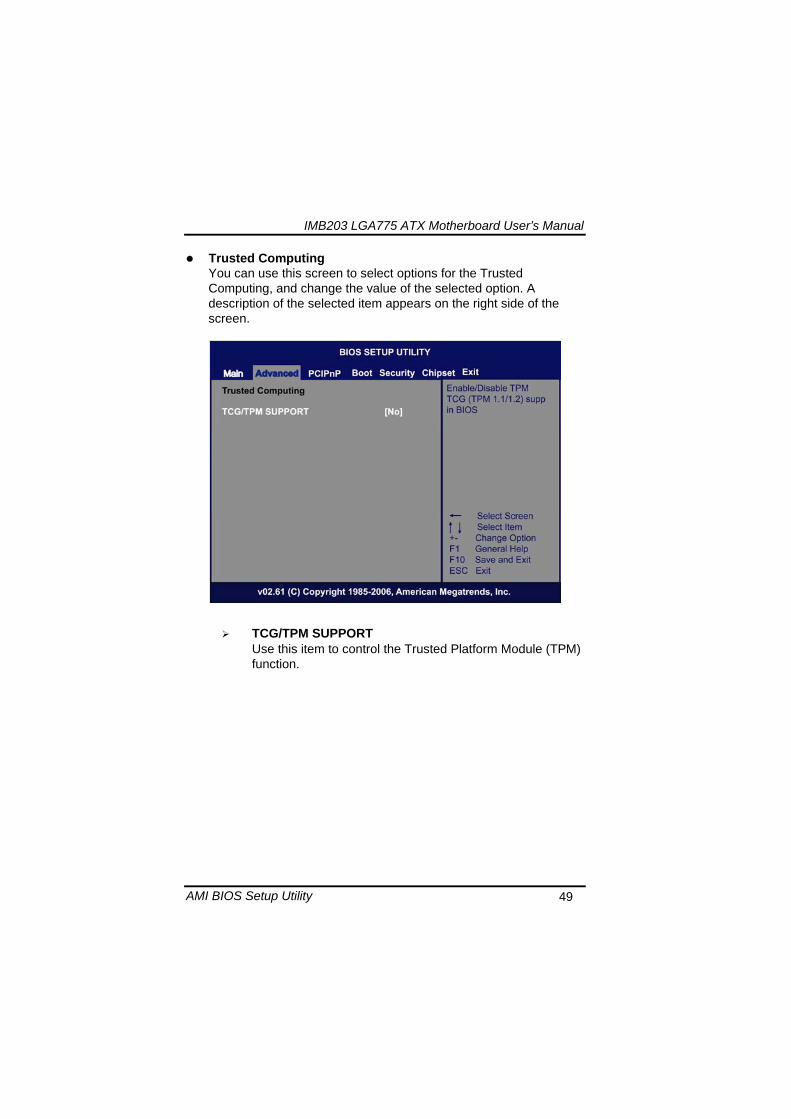
IMB203 LGA775 ATX Motherboard Userrsquos Manual
AMI BIOS Setup Utility 49
Trusted Computing You can use this screen to select options for the Trusted Computing and change the value of the selected option A description of the selected item appears on the right side of the screen
TCGTPM SUPPORT Use this item to control the Trusted Platform Module (TPM) function
IMB203 LGA775 ATX Motherboard Userrsquos Manual
AMI BIOS Setup Utility 50
USB Configuration You can use this screen to select options for the USB Configuration and change the value of the selected option A description of the selected item appears on the right side of the screen
USB Functions
This item allows you to enable or disable USB functions
Legacy USB Support Use this item to enable or disable support for USB device on legacy operating system The default setting is Enabled
USB 20 Controller Mode Use this item to configure the USB 20 controller The default setting is HiSpeed
BIOS EHCI Hand-Off Enabling this item provide the support for operating systems without an EHCI hand-off feature The default setting is Enabled
IMB203 LGA775 ATX Motherboard Userrsquos Manual
AMI BIOS Setup Utility 51
IMB203 LGA775 ATX Motherboard Userrsquos Manual
AMI BIOS Setup Utility 52
55 PCI PnP Menu The PCI PnP menu allows users to change the advanced settings for PCIPnP devices
Clear NVRAM
Use this item to clear the data in the NVRAM (CMOS) Here are the options for your selection No and Yes
Plug amp Play OS When the setting is No Use this item to configure all the devices in the system When the setting is Yes and if you install a Plug and Play operating system the operating system configures the Plug and Play devices not required for boot The default setting is No
IMB203 LGA775 ATX Motherboard Userrsquos Manual
AMI BIOS Setup Utility 53
PCI Latency Timer This item controls how long a PCI device can hold the PCI bus before another takes over The longer the latency the longer the PCI device can retain control of the bus before handing it over to another PCI device There are several options for your selection
Allocate IRQ to PCI VGA This item allows BIOS to choose an IRQ to assign for the PCI VGA card Here are the options for your selection No and Yes
Palette Snooping Some old graphic controllers need to ldquosnooprdquo on the VGA palette and then map it to their display as a way to provide boot information and VGA compatibility This item allows such snooping to take place Here are the options for your selection Disabled and Enabled
PCI IDE BusMaster This item is a toggle for the built-in driver that allows the onboard IDE controller to perform DMA (Direct Memory Access) transfer Here are the options for your selection Disabled and Enabled
OffBoard PCIISA IDE Card This item is for any other non-onboard PCIISA IDE controller adapter There are several options for your selection
IRQ3457910111415 These items will allow you to assign each system interrupt a type depending on the type of device using the interrupt The option ldquoAvailablerdquo means the IRQ is going to assign automatically Here are the options for your selection Available and Reserved
DMA Channel 013567 These items will allow you to assign each DMA channel a type depending on the type of device using the channel The option ldquoAvailablerdquo means the channel is going to assign automatically Here are the options for your selection Available and Reserved
IMB203 LGA775 ATX Motherboard Userrsquos Manual
AMI BIOS Setup Utility 54
56 Boot Menu The Boot menu allows users to change boot options of the system You can select any of the items in the left frame of the screen to go to the sub menus
Boot Settings Configuration Boot Device Priority Removable Drives
For items marked with ldquo rdquo please press ltEntergt for more options
IMB203 LGA775 ATX Motherboard Userrsquos Manual
AMI BIOS Setup Utility 55
Boot Settings Configuration
Quick Boot
Enabling this item lets the BIOS skip some power on self tests (POST) The default setting is Enabled
AddOn ROM Display Mode This item selects the display mode for option ROM The default setting is Force BIOS
Boot Num-Lock Use this item to select the power-on state for the NumLock The default setting is On
PS2 Mouse Support This item determines if the BIOS should reserve IRQ12 for the PS2 mouse or allow other devices to make use of this IRQ Here are the options for your selection Auto Enabled and Disabled
Wait For lsquoF1rsquo Of Error If this item is enabled the system waits for the F1 key to be pressed when error occurs The default setting is Enabled
Hit lsquoDELrsquo Message Display If this item is enabled the system displays the message
IMB203 LGA775 ATX Motherboard Userrsquos Manual
AMI BIOS Setup Utility 56
ldquoPress DEL to run Setuprdquo during POST The default setting is Enabled
Interrupt 19 Capture If this item is enabled this function makes the option ROMs to trap Interrupt 19 The default setting is Disabled
Boot Device Priority The Boot Device Priority screen specifies the boot device priority sequence from the available devices
IMB203 LGA775 ATX Motherboard Userrsquos Manual
AMI BIOS Setup Utility 57
Removable Drives Use this screen to view the removable drives in the system The BIOS will attempt to arrange the removable drive boot sequence automatically You can also change the booting sequence
IMB203 LGA775 ATX Motherboard Userrsquos Manual
AMI BIOS Setup Utility 58
57 Security Menu The Security menu allows users to change the security settings for the system
Supervisor Password
This item indicates whether a supervisor password has been set If the password has been installed Installed displays If not Not Installed displays
User Password This item indicates whether a user password has been set If the password has been installed Installed displays If not Not Installed displays
Change Supervisor Password Select this option and press ltEntergt to access the sub menu You can use the sub menu to change the supervisor password
Change User Password Select this option and press ltEntergt to access the sub menu You can use the sub menu to change the user password
IMB203 LGA775 ATX Motherboard Userrsquos Manual
AMI BIOS Setup Utility 59
58 Chipset Menu The Chipset menu allows users to change the advanced chipset settings You can select any of the items in the left frame of the screen to go to the sub menus
North Bridge Configuration South Bridge Configuration ME Subsystem Configuration
For items marked with ldquo rdquo please press ltEntergt for more options
IMB203 LGA775 ATX Motherboard Userrsquos Manual
AMI BIOS Setup Utility 60
North Bridge Configuration
Memory Remap Feature
Use this item to enable or disable the remapping of the overlapped PCI memory above the total physical memory Only 64-bit OS supports this function
DRAM Frequency This item allows you to control the Memory Clock
Configure DRAM Timing by SPD This item can enable or disable DRAM timing by SPD (Serial Presence Detect) device which is a small EEPROM chip on the memory module containing important information about the module speed size addressing mode and various parameters
Memory Hole You can reserve this area of system memory for ISA adapter ROM When this area is reserved it cannot be cached Check the user information of peripherals that need to use this area o f system memory for the memory requirements Here are the options Disabled and 15M-16M
IMB203 LGA775 ATX Motherboard Userrsquos Manual
AMI BIOS Setup Utility 61
Initiate Graphic Adapter When using multiple graphics cards this item can select which graphics controller to be the primary display device during boot
IGD Graphics Mode Select This item allows you to select the amount of system memory used by the internal graphics device
PEG Port ConfigurationPEG Port This item is a toggle to enable or disable the PCI Express port Here are the options for your selection Auto and Disabled
Video Function Configuration Press ltEntergt for the sub-menu for setting up video function
IMB203 LGA775 ATX Motherboard Userrsquos Manual
AMI BIOS Setup Utility 62
South Bridge Configuration
GbE Wake Up From S5 This item specifies whether the system will be awakened from the S5 power
HDA Controller This item allows you to enable or disable the HD audio support
Restore on AC Power Loss This item can control how the PC will behave once power is restored following a power outage or other unexpected shutdown
PCIE Port Configuration This item allows you to set or disable the PCI Express Ports
IMB203 LGA775 ATX Motherboard Userrsquos Manual
AMI BIOS Setup Utility 63
ME Subsystem Configuration
It is strongly recommended that you do not modify these options unless you are an advanced user
IMB203 LGA775 ATX Motherboard Userrsquos Manual
AMI BIOS Setup Utility 64
59 Exit Menu The Exit menu allows users to load your system configuration with optimal or failsafe default values
Save Changes and Exit
When you have completed the system configuration changes select this option to leave Setup and reboot the computer so the new system configuration parameters can take effect Select Save Changes and Exit from the Exit menu and press ltEntergt Select Ok to save changes and exit
Discard Changes and Exit Select this option to quit Setup without making any permanent changes to the system configuration Select Discard Changes and Exit from the Exit menu and press ltEntergt Select Ok to discard changes and exit
Load Optimal Defaults It automatically sets all Setup options to a complete set of default settings when you select this option The Optimal settings are designed for maximum system performance but may not work best for all computer applications In particular do not use the Optimal Setup options if your
IMB203 LGA775 ATX Motherboard Userrsquos Manual
AMI BIOS Setup Utility 65
computer is experiencing system configuration problems Select Load Optimal Defaults from the Exit menu and press ltEntergt
Load Fail-Safe Defaults It automatically sets all Setup options to a complete set of default settings when you select this option The Fail-Safe settings are designed for maximum system stability but not maximum performance Select the Fail-Safe Setup options if your computer is experiencing system configuration problems Select Load Fail-Safe Defaults from the Exit menu and press ltEntergt Select Ok to load Fail-Safe defaults
IMB203 LGA775 ATX Motherboard Userrsquos Manual
AMI BIOS Setup Utility 66
MEMO
IMB203 LGA775 ATX Motherboard Userrsquos Manual
Installation of Drivers 67
CHPATER 6 INSTALLATION OF DRIVERS
The device drivers are located on the Product Information CD-ROM that comes with the IMB203 Series package The auto-run function of drivers will guide you to install the utilities and device drivers under a Windows system You can follow the onscreen instructions to install these devices
Chipse VGA LAN Audio iAMT MEI
61 Installing Chipset Driver 1 Run the SETUPEXE program from the driver directory in
your driver CD Click ldquoNextrdquo to next step
IMB203 LGA775 ATX Motherboard Userrsquos Manual
Installation of Drivers 68
2 An Intelreg License Agreement appears to show you the important information Click ldquoYesrdquo to next step
3 Refer to the Readme file below to view the system requirements and installation information
IMB203 LGA775 ATX Motherboard Userrsquos Manual
Installation of Drivers 69
3-1 Please wait while running the following setup operations
3-2 Please wait while running the following setup operations
IMB203 LGA775 ATX Motherboard Userrsquos Manual
Installation of Drivers 70
4 Click ldquoFinishrdquo to complete the setup process
5 You will be asked to reboot your computer when the installation is completed Please click ldquoYes I want to restart my computer nowrdquo if you donrsquot need to install any other drivers Otherwise please click ldquoNo I will restart my computer laterrdquo and go on next step
IMB203 LGA775 ATX Motherboard Userrsquos Manual
Installation of Drivers 71
62 Installing VGA Driver 1 Run the SETUPEXE program from the driver directory in
your driver CD Click ldquoNextrdquo to next step
2 An Intelreg License Agreement appears to show you the
important information Click ldquoYesrdquo to next step
IMB203 LGA775 ATX Motherboard Userrsquos Manual
Installation of Drivers 72
3 The message of Readme File Information appears to show you the system requirements and installation information Please click ldquoNextrdquo
4 Please wait while running the following setup operations
When this message appears please click ldquoNextrdquo
IMB203 LGA775 ATX Motherboard Userrsquos Manual
Installation of Drivers 73
5 Click ldquoFinishrdquo to complete the setup process
6 You will be asked to reboot your computer when the installation is completed Please click ldquoYes I want to restart my computer nowrdquo if you donrsquot need to install any other drivers Otherwise please click ldquoNo I will restart my computer laterrdquo and click ldquoFinishrdquo to complete the installation
IMB203 LGA775 ATX Motherboard Userrsquos Manual
Installation of Drivers 74
63 Installing LAN Driver
11 Run the InstallShield Wizard for Network Connections from
the driver directory in your driver CD Click ldquoNextrdquo to next step
IMB203 LGA775 ATX Motherboard Userrsquos Manual
Installation of Drivers 75
12 An Intelreg License Agreement appears to show you the important information Click ldquoYesrdquo to next step
13 A Setup Options window appears that you can select the
program features you want to install
IMB203 LGA775 ATX Motherboard Userrsquos Manual
Installation of Drivers 76
2 Click ldquoInstallrdquo to start the installation
3 Please wait while running the following installation operation
IMB203 LGA775 ATX Motherboard Userrsquos Manual
Installation of Drivers 77
4 Click ldquoFinishrdquo to complete the installation
Note The Driver item [Wake on Directed Packet] default is Enabled under Windows Vista
格式化 字型 (符號) Arial
格式化 字型 (符號) Arial
格式化 字型 斜體 字型色彩 黑色 (符號) Arial 非加寬 緊縮
格式化 字型 斜體 字型色彩 黑色 (符號) Arial 非加寬 緊縮
格式化 字型 (符號) Arial 非加寬 緊縮
IMB203 LGA775 ATX Motherboard Userrsquos Manual
Installation of Drivers 78
64 Installing AUDIO Driver 1 Run the InstallShield Wizard for Realtek High Definition
Audio Driver from the driver directory in your driver CD Click ldquoNextrdquo to next step
IMB203 LGA775 ATX Motherboard Userrsquos Manual
Installation of Drivers 79
2 Click ldquoInstallrdquo to start the installation and wait while running the installation operation
3 Click ldquoFinishrdquo to complete the installation
IMB203 LGA775 ATX Motherboard Userrsquos Manual
Installation of Drivers 80
65 Installing iAMT (Active Management Technology) Driver
Note You must download and properly install the required NET version 35 provided from a separate downloading of the actual FimwareTools kit releases posted on VIP prior to loading the MEILMS Driver stack
651 LMS_SOL Setup
1 Run the setup program to install Intelreg Active Management Technology onto your computer It is strongly recommended that you exit all programs before continuing Click ldquoNextrdquo to next step
格式化 字型 (符號) Arial
格式化 字型 (符號) Arial 非加寬 緊縮
IMB203 LGA775 ATX Motherboard Userrsquos Manual
Installation of Drivers 81
2 An Intelreg license agreement appears that you need to continue the setup program by clicking ldquoYesrdquo to accept the terms
IMB203 LGA775 ATX Motherboard Userrsquos Manual
Installation of Drivers 82
3 Refer to the Readme file below to view the system requirements and installation information Click ldquoNextrdquo to next setup
4 Please wait while running the following installation operation
IMB203 LGA775 ATX Motherboard Userrsquos Manual
Installation of Drivers 83
5 Click ldquoFinishrdquo to complete the installation
IMB203 LGA775 ATX Motherboard Userrsquos Manual
Installation of Drivers 84
652 LMS_SOL_IS Setup
1 Run the setup program to install Intelreg Active Management Technology onto your computer It is strongly recommended that you exit all programs before continuing Click ldquoNextrdquo to next step
IMB203 LGA775 ATX Motherboard Userrsquos Manual
Installation of Drivers 85
2 An Intelreg license agreement appears that you need to continue the setup program by clicking ldquoYesrdquo to accept the terms
IMB203 LGA775 ATX Motherboard Userrsquos Manual
Installation of Drivers 86
3 Refer to the Readme file below to view the system requirements and installation information Click ldquoNextrdquo to next setup
4 Please wait while running the following installation operation
IMB203 LGA775 ATX Motherboard Userrsquos Manual
Installation of Drivers 87
5 Click ldquoFinishrdquo to complete the installation
IMB203 LGA775 ATX Motherboard Userrsquos Manual
Installation of Drivers 88
66 Installing MEI (Management Engine Interface) Driver
Note You must download and properly install the required NET version 35 provided from a separate downloading of the actual FimwareTools kit releases posted on VIP prior to loading the MEILMS Driver stack
1 Run the setup program to install Intelreg Management Engine
Interface onto your computer It is strongly recommended that you exit all programs before continuing Click ldquoNextrdquo to next step
格式化 字型 (符號) Arial
格式化 字型 (符號) Arial 非加寬 緊縮
IMB203 LGA775 ATX Motherboard Userrsquos Manual
Installation of Drivers 89
2 An Intelreg license agreement appears that you need to continue the setup program by clicking ldquoYesrdquo to accept the terms
IMB203 LGA775 ATX Motherboard Userrsquos Manual
Installation of Drivers 90
3 Refer to the Readme file below to view the system requirements and installation information Click ldquoNextrdquo to next setup
4 Please wait while running the following installation operation
IMB203 LGA775 ATX Motherboard Userrsquos Manual
Installation of Drivers 91
5 Click ldquoFinishrdquo to complete the installation
IMB203 LGA775 ATX Motherboard Userrsquos Manual
Installation of Drivers 92
MEMO
IMB203 LGA775 ATX Motherboard Userrsquos Manual
Watchdog Timer 93
APPENDIX A WATCHDOG TIMER
Watchdog Timer Setting After the system stops working for a while it can be auto-reset by the Watchdog Timer The integrated Watchdog Timer can be set up in the system reset mode by program
Using the Watchdog Function Start darr Un-Lock WDT O 2E 87 Un-lock super IO
O 2E 87 Un-lock super IO darr Set WDT Function O 2E 2D O 2F 20 Select Logic device O 2E 07 O 2F 08 darr Activate WDT O 2E 30
O 2F 01 Set Second or Minute O 2E F5
O 2F N N=00 or 08(See below table) darr Set base timer O 2E F6
O 2F M=000102hellipFF(Hex) Value=0 to 255 darr WDT counting
re-set timer O 2E F6
O 2F M M=000102hellipFF(See below table) darr
格式化
格式化 項目符號及編號
格式化 項目符號及編號
格式化 字型 8 點 字型色彩黑色
格式化 字型 8 點 字型色彩黑色
格式化 定位點 1257 字元左 + 不在 1012 字元 + 1386字元
格式化 字型 8 點 字型色彩黑色
格式化 定位點 1257 字元左 + 不在 134 字元 + 1362字元
格式化 字型色彩 黑色
格式化 字型色彩 黑色
刪除
IMB203 LGA775 ATX Motherboard Userrsquos Manual
Watchdog Timer 94
IF No re-set timer WDT time-out generate RESET IF to disable WDT O 2E 30
O 2F 00 Can be disable at any time
N=00
M= 00h Time-out Disable 01h Time-out occurs after 1 second 02h Time-out occurs after 2 second 03h Time-out occurs after 3 second helliphelliphelliphelliphelliphelliphelliphelliphellip FFh Time-out occurs after 255 second
N=08
M= 00h Time-out Disable 01h Time-out occurs after 1 minute 02h Time-out occurs after 2 minutes 03h Time-out occurs after 3 minutes helliphelliphelliphelliphelliphelliphelliphelliphellip
FFh Time-out occurs after 255 minutes
格式化 字型色彩 黑色
格式化 字型色彩 黑色
IMB203 LGA775 ATX Motherboard Userrsquos Manual
PCI IRQ Routing 95
APPENDIX B PCI IRQ ROUTING
PICMG PCI IRQ Routing
Device ID Slot Int
PCI Slot 0 31 0 BCDA PCI Slot 1 30 1 CDAB PCI Slot 2 29 2 DABC PCI Slot 3 28 3 ABCD
IMB203 LGA775 ATX Motherboard Userrsquos Manual
PCI IRQ Routing 96
MEMO
IMB203 LGA775 ATX Motherboard Userrsquos Manual
Configuring SATA for RAID Function 97
APPENDIX C CONFIGURING SATA FOR RAID
FUNCTION
Configuring SATA Hard Drive(s) for RAID Function (Controller IntelregICH10DODO DH only) Please follow up the steps below to configure SATA hard drive(s) (1) Install SATA hard drive(s) in your system (2) Enter the BIOS Setup to configure SATA controller mode and boot
sequence (3) Configure RAID by the RAID BIOS (4) Install the SATA controller driver during the OS installation Before you begin the SATA configuration please prepare (a) Two SATA hard drives (to ensure optimal performance it is
recommended that you use two hard drives with identical model and capacity) If you do not want to create RAID with the SATA controller you may prepare only one hard drive
(b) An empty formatted floppy disk (c) Windows XP setup disk (1) Installing SATA hard drive(s) in your system
Connect one end of the SATA signal cable to the rear of the SATA hard drive and the other end to available SATA port(s) on the board Then connect the power connector of power supply to the hard drive
(2) Configuring SATA controller mode and boot sequence by the BIOS Setup You have to make sure whether the SATA controller is configured correctly by system BIOS Setup and set up BIOS boot sequence for the SATA hard drive(s)
IMB203 LGA775 ATX Motherboard Userrsquos Manual
Configuring SATA for RAID Function 98
(2)-1-1 Turn on your system and then press the Del button to enter BIOS Setup during running POST (Power-On Self Test) If you want to create RAID just go to the Advanced Settings menuIDE configuration select the Configure SATA1 as and press ltEntergt for more options
IMB203 LGA775 ATX Motherboard Userrsquos Manual
Configuring SATA for RAID Function 99
(2)-1-2 A list of options appears please select RAID
IMB203 LGA775 ATX Motherboard Userrsquos Manual
Configuring SATA for RAID Function 100
(2)-2 Set CDROM for First Boot Device under the Boot Settings menu to boot CD-ROM after system restarts
(2)-3 Save and exit the BIOS Setup
IMB203 LGA775 ATX Motherboard Userrsquos Manual
Configuring SATA for RAID Function 101
(3) Configuring RAID by the RAID BIOS Enter the RAID BIOS setup utility to configure a RAID array Skip this step and proceed to Section 4 if you do not want to create a RAID (3)-1 After the POST memory testing and before the operating
system booting a message Press ltCtrl-Igt to enter Configuration Utility shows up accordingly press ltCTRL+ Igt to enter the RAID BIOS setup utility
(3)-2 After you press ltCTRL+ Igt the Create RAID Volume screen will appear If you want to create a RAID array select the Create RAID Volume option in the Main Menu and press ENTER
IMB203 LGA775 ATX Motherboard Userrsquos Manual
Configuring SATA for RAID Function 102
(3)-3-1 After entering the CREATE VOLUME MENU screen you can type the disk array name with 1~16 letters (letters cannot be special characters) in the item ldquoNamerdquo
(3)-3-2 When finished press ENTER to select a RAID level There are three RAID levels RAID0 RAID1 and RAID5 amp RAID10 Select a RAID level and press ENTER
IMB203 LGA775 ATX Motherboard Userrsquos Manual
Configuring SATA for RAID Function 103
(3)-4 Set the stripe block size The KB is the standard unit of stripe block size The stripe block size can be 4KB to 128KB After the setting press ENTER for the array capacity
(3)-5 After setting all the items on the menu select Create Volume
and press ENTER to start creating the RAID array
IMB203 LGA775 ATX Motherboard Userrsquos Manual
Configuring SATA for RAID Function 104
(3)-6 When prompting the confirmation press ldquoYldquo to create this volume or ldquoNldquo to cancel the creation
After the creation is completed you can see detailed information about the RAID Array in the DISKVOLUME INFORMATION section including RAID mode disk block size disk name and disk capacity etc
IMB203 LGA775 ATX Motherboard Userrsquos Manual
Configuring SATA for RAID Function 105
Delete RAID Volume If you want to delete a RAID volume select the Delete RAID Volume option in Main Menu Press ENTER and follow on-screen instructions
Please press [ESC] to exit the RAID BIOS utility Now you can proceed to install a SATA driver controller and the operating system
IMB203 LGA775 ATX Motherboard Userrsquos Manual
Configuring SATA for RAID Function 106
(4) Making a SATA Driver Disk To install the operating system onto a serial ATA hard disk successfully you need to install the SATA controller driver during the OS installation Without the driver the hard disk may not be recognized during the Windows setup process First of all please format a blank floppy disk Secondly follow up these steps below to produce a SATA driver disk Users can insert the Driver CD and the formatted blank floppy disk in another system And then please copy all of file of the f6flpy32 folder in the Driver CD to a floppy disk Note Please copy all of file of the f6flpy64 folder if installing 64-bit
Windows Operating System
IMB203 LGA775 ATX Motherboard Userrsquos Manual
Configuring SATA for RAID Function 107
(5) Installing the SATA controller driver during the OS installation Now the SATA driver disk is ready and BIOS settings configured you can proceed to install Windows 2000XP onto your SATA hard drive using the SATA driver Here is an example for Windows XP installation (5)-1 Restart your system to boot the Windows 2000XP Setup disk
and press F6 button as soon as you see the message Press F6 if you need to install a 3rd party SCSI or RAID driver After pressing the F6 button there will be a few moments for some files being loaded before next screen appears
IMB203 LGA775 ATX Motherboard Userrsquos Manual
Configuring SATA for RAID Function 108
(5)-2 When you see the screen below insert the floppy disk containing the SATA driver and press ldquoSrdquo
(5)-3 If the Setup correctly recognizes the driver of the floppy disk
a controller menu will appear below Use the ARROW keys to select Intel(R) ICH8RICH9RICH10RDO SATA RAID Controller and press ENTER Then it will begin to load the SATA driver from the floppy disk
IMB203 LGA775 ATX Motherboard Userrsquos Manual
Configuring SATA for RAID Function 109
Note If a message on the screen saying that one or some file(s) cannot be found please check the floppy disk or copy the correct SATA driver again from the driver CD
IMB203 LGA775 ATX Motherboard Userrsquos Manual
Configuring SATA for RAID Function 110
MEMO
IMB203 LGA775 ATX Motherboard Userrsquos Manual
iAMT Settings 111
APPENDIX D iAMT SETTINGS
The Intelreg Active Management Technology (Intelreg iAMT) has decreased a major barrier to IT efficiency that uses built-in platform capabilities and popular third-party management and security applications to allow IT a better discovering healing and protection their networked computing assets In order to utilize Intel iAMT you must enter the ME BIOS (CTRL + P during system startup) change the ME BIOS password and then select ldquoIntelreg iAMTrdquo as the manageability feature
D1 Entering MEBx 1 You must go to BIOS TO start iAMT function 2 Exit from BIOS after starting iAMT and press Ctrl+P to enter MEBx Setting
It is better to press Ctrl+P before the screen popping out
格式化
IMB203 LGA775 ATX Motherboard Userrsquos Manual
iAMT Settings 112
D2 Set amp Change Password 1 You will be asked to set a password when first log in The default
password is lsquoadminrsquo
2 You will be asked to change the password before setting ME
Change Password
IMB203 LGA775 ATX Motherboard Userrsquos Manual
iAMT Settings 113
3 You must confirm your new password while revising (as Remark 1)
Remark 1 The new password must contain (example 11qqQQ) (default value)
Eight characters
One upper case
One lower case
One number
One special symbol such as $ or
( excepted)
Underline ( _ ) and space are valid characters for password but they wonrsquot make higher complexity
IMB203 LGA775 ATX Motherboard Userrsquos Manual
iAMT Settings 114
D3 Intelreg iAMT Settings 1 Select Intelreg iAMT Configuration and press ltENTERgt
2 Key in the Host Name If Intelreg iAMT set to lsquoDHCPlsquo the Host name must be identical to the operating system mechanic
IMB203 LGA775 ATX Motherboard Userrsquos Manual
iAMT Settings 115
3 Select TCPIP to get into Network interface and set it to lsquoENABLEDrsquo into DHCP Mode and set it to lsquoDISABLEDrsquo (as Remark 2) into Domain name and set the Intel Management Engine domain name such as lsquoAMTintelcomrsquo
(3-1)
(3-2)
IMB203 LGA775 ATX Motherboard Userrsquos Manual
iAMT Settings 116
Remark 2 DHCP Mode lsquoDISABLEDlsquo if DHCP Mode is disabled you can make the following settings
IP address
Subnet mask
IMB203 LGA775 ATX Motherboard Userrsquos Manual
iAMT Settings 117
Default Gateway address
Preferred DNS address
IMB203 LGA775 ATX Motherboard Userrsquos Manual
iAMT Settings 118
Alternate DNS address
Domain name
4 Exit from MEBx after completing the iAMT settings
IMB203 LGA775 ATX Motherboard Userrsquos Manual
iAMT Settings 119
D4 iAMT Web Console 1 From a web browser please type http(IP ADDRESS)16992
which connects to iAMT Web Example http1014021416992
2 To log on you will be required to type in username and password
for access to the Web
USER admin (default value)
PASS (MEBx password)
IMB203 LGA775 ATX Motherboard Userrsquos Manual
iAMT Settings 120
3 Enter the iAMT Web
4 Click Remote Control and select commands on the right side
IMB203 LGA775 ATX Motherboard Userrsquos Manual
iAMT Settings 121
5 When you have finished using the iAMT Web console close the Web browser
IMB203 LGA775 ATX Motherboard Userrsquos Manual
iAMT Settings 122
MEMO
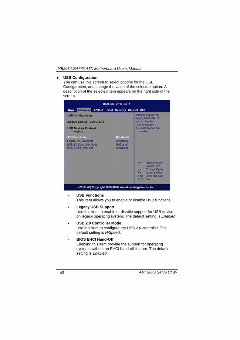
IMB203 LGA775 ATX Motherboard Userrsquos Manual
AMI BIOS Setup Utility 53
PCI Latency Timer This item controls how long a PCI device can hold the PCI bus before another takes over The longer the latency the longer the PCI device can retain control of the bus before handing it over to another PCI device There are several options for your selection
Allocate IRQ to PCI VGA This item allows BIOS to choose an IRQ to assign for the PCI VGA card Here are the options for your selection No and Yes
Palette Snooping Some old graphic controllers need to ldquosnooprdquo on the VGA palette and then map it to their display as a way to provide boot information and VGA compatibility This item allows such snooping to take place Here are the options for your selection Disabled and Enabled
PCI IDE BusMaster This item is a toggle for the built-in driver that allows the onboard IDE controller to perform DMA (Direct Memory Access) transfer Here are the options for your selection Disabled and Enabled
OffBoard PCIISA IDE Card This item is for any other non-onboard PCIISA IDE controller adapter There are several options for your selection
IRQ3457910111415 These items will allow you to assign each system interrupt a type depending on the type of device using the interrupt The option ldquoAvailablerdquo means the IRQ is going to assign automatically Here are the options for your selection Available and Reserved
DMA Channel 013567 These items will allow you to assign each DMA channel a type depending on the type of device using the channel The option ldquoAvailablerdquo means the channel is going to assign automatically Here are the options for your selection Available and Reserved
IMB203 LGA775 ATX Motherboard Userrsquos Manual
AMI BIOS Setup Utility 54
56 Boot Menu The Boot menu allows users to change boot options of the system You can select any of the items in the left frame of the screen to go to the sub menus
Boot Settings Configuration Boot Device Priority Removable Drives
For items marked with ldquo rdquo please press ltEntergt for more options
IMB203 LGA775 ATX Motherboard Userrsquos Manual
AMI BIOS Setup Utility 55
Boot Settings Configuration
Quick Boot
Enabling this item lets the BIOS skip some power on self tests (POST) The default setting is Enabled
AddOn ROM Display Mode This item selects the display mode for option ROM The default setting is Force BIOS
Boot Num-Lock Use this item to select the power-on state for the NumLock The default setting is On
PS2 Mouse Support This item determines if the BIOS should reserve IRQ12 for the PS2 mouse or allow other devices to make use of this IRQ Here are the options for your selection Auto Enabled and Disabled
Wait For lsquoF1rsquo Of Error If this item is enabled the system waits for the F1 key to be pressed when error occurs The default setting is Enabled
Hit lsquoDELrsquo Message Display If this item is enabled the system displays the message
IMB203 LGA775 ATX Motherboard Userrsquos Manual
AMI BIOS Setup Utility 56
ldquoPress DEL to run Setuprdquo during POST The default setting is Enabled
Interrupt 19 Capture If this item is enabled this function makes the option ROMs to trap Interrupt 19 The default setting is Disabled
Boot Device Priority The Boot Device Priority screen specifies the boot device priority sequence from the available devices
IMB203 LGA775 ATX Motherboard Userrsquos Manual
AMI BIOS Setup Utility 57
Removable Drives Use this screen to view the removable drives in the system The BIOS will attempt to arrange the removable drive boot sequence automatically You can also change the booting sequence
IMB203 LGA775 ATX Motherboard Userrsquos Manual
AMI BIOS Setup Utility 58
57 Security Menu The Security menu allows users to change the security settings for the system
Supervisor Password
This item indicates whether a supervisor password has been set If the password has been installed Installed displays If not Not Installed displays
User Password This item indicates whether a user password has been set If the password has been installed Installed displays If not Not Installed displays
Change Supervisor Password Select this option and press ltEntergt to access the sub menu You can use the sub menu to change the supervisor password
Change User Password Select this option and press ltEntergt to access the sub menu You can use the sub menu to change the user password
IMB203 LGA775 ATX Motherboard Userrsquos Manual
AMI BIOS Setup Utility 59
58 Chipset Menu The Chipset menu allows users to change the advanced chipset settings You can select any of the items in the left frame of the screen to go to the sub menus
North Bridge Configuration South Bridge Configuration ME Subsystem Configuration
For items marked with ldquo rdquo please press ltEntergt for more options
IMB203 LGA775 ATX Motherboard Userrsquos Manual
AMI BIOS Setup Utility 60
North Bridge Configuration
Memory Remap Feature
Use this item to enable or disable the remapping of the overlapped PCI memory above the total physical memory Only 64-bit OS supports this function
DRAM Frequency This item allows you to control the Memory Clock
Configure DRAM Timing by SPD This item can enable or disable DRAM timing by SPD (Serial Presence Detect) device which is a small EEPROM chip on the memory module containing important information about the module speed size addressing mode and various parameters
Memory Hole You can reserve this area of system memory for ISA adapter ROM When this area is reserved it cannot be cached Check the user information of peripherals that need to use this area o f system memory for the memory requirements Here are the options Disabled and 15M-16M
IMB203 LGA775 ATX Motherboard Userrsquos Manual
AMI BIOS Setup Utility 61
Initiate Graphic Adapter When using multiple graphics cards this item can select which graphics controller to be the primary display device during boot
IGD Graphics Mode Select This item allows you to select the amount of system memory used by the internal graphics device
PEG Port ConfigurationPEG Port This item is a toggle to enable or disable the PCI Express port Here are the options for your selection Auto and Disabled
Video Function Configuration Press ltEntergt for the sub-menu for setting up video function
IMB203 LGA775 ATX Motherboard Userrsquos Manual
AMI BIOS Setup Utility 62
South Bridge Configuration
GbE Wake Up From S5 This item specifies whether the system will be awakened from the S5 power
HDA Controller This item allows you to enable or disable the HD audio support
Restore on AC Power Loss This item can control how the PC will behave once power is restored following a power outage or other unexpected shutdown
PCIE Port Configuration This item allows you to set or disable the PCI Express Ports
IMB203 LGA775 ATX Motherboard Userrsquos Manual
AMI BIOS Setup Utility 63
ME Subsystem Configuration
It is strongly recommended that you do not modify these options unless you are an advanced user
IMB203 LGA775 ATX Motherboard Userrsquos Manual
AMI BIOS Setup Utility 64
59 Exit Menu The Exit menu allows users to load your system configuration with optimal or failsafe default values
Save Changes and Exit
When you have completed the system configuration changes select this option to leave Setup and reboot the computer so the new system configuration parameters can take effect Select Save Changes and Exit from the Exit menu and press ltEntergt Select Ok to save changes and exit
Discard Changes and Exit Select this option to quit Setup without making any permanent changes to the system configuration Select Discard Changes and Exit from the Exit menu and press ltEntergt Select Ok to discard changes and exit
Load Optimal Defaults It automatically sets all Setup options to a complete set of default settings when you select this option The Optimal settings are designed for maximum system performance but may not work best for all computer applications In particular do not use the Optimal Setup options if your
IMB203 LGA775 ATX Motherboard Userrsquos Manual
AMI BIOS Setup Utility 65
computer is experiencing system configuration problems Select Load Optimal Defaults from the Exit menu and press ltEntergt
Load Fail-Safe Defaults It automatically sets all Setup options to a complete set of default settings when you select this option The Fail-Safe settings are designed for maximum system stability but not maximum performance Select the Fail-Safe Setup options if your computer is experiencing system configuration problems Select Load Fail-Safe Defaults from the Exit menu and press ltEntergt Select Ok to load Fail-Safe defaults
IMB203 LGA775 ATX Motherboard Userrsquos Manual
AMI BIOS Setup Utility 66
MEMO
IMB203 LGA775 ATX Motherboard Userrsquos Manual
Installation of Drivers 67
CHPATER 6 INSTALLATION OF DRIVERS
The device drivers are located on the Product Information CD-ROM that comes with the IMB203 Series package The auto-run function of drivers will guide you to install the utilities and device drivers under a Windows system You can follow the onscreen instructions to install these devices
Chipse VGA LAN Audio iAMT MEI
61 Installing Chipset Driver 1 Run the SETUPEXE program from the driver directory in
your driver CD Click ldquoNextrdquo to next step
IMB203 LGA775 ATX Motherboard Userrsquos Manual
Installation of Drivers 68
2 An Intelreg License Agreement appears to show you the important information Click ldquoYesrdquo to next step
3 Refer to the Readme file below to view the system requirements and installation information
IMB203 LGA775 ATX Motherboard Userrsquos Manual
Installation of Drivers 69
3-1 Please wait while running the following setup operations
3-2 Please wait while running the following setup operations
IMB203 LGA775 ATX Motherboard Userrsquos Manual
Installation of Drivers 70
4 Click ldquoFinishrdquo to complete the setup process
5 You will be asked to reboot your computer when the installation is completed Please click ldquoYes I want to restart my computer nowrdquo if you donrsquot need to install any other drivers Otherwise please click ldquoNo I will restart my computer laterrdquo and go on next step
IMB203 LGA775 ATX Motherboard Userrsquos Manual
Installation of Drivers 71
62 Installing VGA Driver 1 Run the SETUPEXE program from the driver directory in
your driver CD Click ldquoNextrdquo to next step
2 An Intelreg License Agreement appears to show you the
important information Click ldquoYesrdquo to next step
IMB203 LGA775 ATX Motherboard Userrsquos Manual
Installation of Drivers 72
3 The message of Readme File Information appears to show you the system requirements and installation information Please click ldquoNextrdquo
4 Please wait while running the following setup operations
When this message appears please click ldquoNextrdquo
IMB203 LGA775 ATX Motherboard Userrsquos Manual
Installation of Drivers 73
5 Click ldquoFinishrdquo to complete the setup process
6 You will be asked to reboot your computer when the installation is completed Please click ldquoYes I want to restart my computer nowrdquo if you donrsquot need to install any other drivers Otherwise please click ldquoNo I will restart my computer laterrdquo and click ldquoFinishrdquo to complete the installation
IMB203 LGA775 ATX Motherboard Userrsquos Manual
Installation of Drivers 74
63 Installing LAN Driver
11 Run the InstallShield Wizard for Network Connections from
the driver directory in your driver CD Click ldquoNextrdquo to next step
IMB203 LGA775 ATX Motherboard Userrsquos Manual
Installation of Drivers 75
12 An Intelreg License Agreement appears to show you the important information Click ldquoYesrdquo to next step
13 A Setup Options window appears that you can select the
program features you want to install
IMB203 LGA775 ATX Motherboard Userrsquos Manual
Installation of Drivers 76
2 Click ldquoInstallrdquo to start the installation
3 Please wait while running the following installation operation
IMB203 LGA775 ATX Motherboard Userrsquos Manual
Installation of Drivers 77
4 Click ldquoFinishrdquo to complete the installation
Note The Driver item [Wake on Directed Packet] default is Enabled under Windows Vista
格式化 字型 (符號) Arial
格式化 字型 (符號) Arial
格式化 字型 斜體 字型色彩 黑色 (符號) Arial 非加寬 緊縮
格式化 字型 斜體 字型色彩 黑色 (符號) Arial 非加寬 緊縮
格式化 字型 (符號) Arial 非加寬 緊縮
IMB203 LGA775 ATX Motherboard Userrsquos Manual
Installation of Drivers 78
64 Installing AUDIO Driver 1 Run the InstallShield Wizard for Realtek High Definition
Audio Driver from the driver directory in your driver CD Click ldquoNextrdquo to next step
IMB203 LGA775 ATX Motherboard Userrsquos Manual
Installation of Drivers 79
2 Click ldquoInstallrdquo to start the installation and wait while running the installation operation
3 Click ldquoFinishrdquo to complete the installation
IMB203 LGA775 ATX Motherboard Userrsquos Manual
Installation of Drivers 80
65 Installing iAMT (Active Management Technology) Driver
Note You must download and properly install the required NET version 35 provided from a separate downloading of the actual FimwareTools kit releases posted on VIP prior to loading the MEILMS Driver stack
651 LMS_SOL Setup
1 Run the setup program to install Intelreg Active Management Technology onto your computer It is strongly recommended that you exit all programs before continuing Click ldquoNextrdquo to next step
格式化 字型 (符號) Arial
格式化 字型 (符號) Arial 非加寬 緊縮
IMB203 LGA775 ATX Motherboard Userrsquos Manual
Installation of Drivers 81
2 An Intelreg license agreement appears that you need to continue the setup program by clicking ldquoYesrdquo to accept the terms
IMB203 LGA775 ATX Motherboard Userrsquos Manual
Installation of Drivers 82
3 Refer to the Readme file below to view the system requirements and installation information Click ldquoNextrdquo to next setup
4 Please wait while running the following installation operation
IMB203 LGA775 ATX Motherboard Userrsquos Manual
Installation of Drivers 83
5 Click ldquoFinishrdquo to complete the installation
IMB203 LGA775 ATX Motherboard Userrsquos Manual
Installation of Drivers 84
652 LMS_SOL_IS Setup
1 Run the setup program to install Intelreg Active Management Technology onto your computer It is strongly recommended that you exit all programs before continuing Click ldquoNextrdquo to next step
IMB203 LGA775 ATX Motherboard Userrsquos Manual
Installation of Drivers 85
2 An Intelreg license agreement appears that you need to continue the setup program by clicking ldquoYesrdquo to accept the terms
IMB203 LGA775 ATX Motherboard Userrsquos Manual
Installation of Drivers 86
3 Refer to the Readme file below to view the system requirements and installation information Click ldquoNextrdquo to next setup
4 Please wait while running the following installation operation
IMB203 LGA775 ATX Motherboard Userrsquos Manual
Installation of Drivers 87
5 Click ldquoFinishrdquo to complete the installation
IMB203 LGA775 ATX Motherboard Userrsquos Manual
Installation of Drivers 88
66 Installing MEI (Management Engine Interface) Driver
Note You must download and properly install the required NET version 35 provided from a separate downloading of the actual FimwareTools kit releases posted on VIP prior to loading the MEILMS Driver stack
1 Run the setup program to install Intelreg Management Engine
Interface onto your computer It is strongly recommended that you exit all programs before continuing Click ldquoNextrdquo to next step
格式化 字型 (符號) Arial
格式化 字型 (符號) Arial 非加寬 緊縮
IMB203 LGA775 ATX Motherboard Userrsquos Manual
Installation of Drivers 89
2 An Intelreg license agreement appears that you need to continue the setup program by clicking ldquoYesrdquo to accept the terms
IMB203 LGA775 ATX Motherboard Userrsquos Manual
Installation of Drivers 90
3 Refer to the Readme file below to view the system requirements and installation information Click ldquoNextrdquo to next setup
4 Please wait while running the following installation operation
IMB203 LGA775 ATX Motherboard Userrsquos Manual
Installation of Drivers 91
5 Click ldquoFinishrdquo to complete the installation
IMB203 LGA775 ATX Motherboard Userrsquos Manual
Installation of Drivers 92
MEMO
IMB203 LGA775 ATX Motherboard Userrsquos Manual
Watchdog Timer 93
APPENDIX A WATCHDOG TIMER
Watchdog Timer Setting After the system stops working for a while it can be auto-reset by the Watchdog Timer The integrated Watchdog Timer can be set up in the system reset mode by program
Using the Watchdog Function Start darr Un-Lock WDT O 2E 87 Un-lock super IO
O 2E 87 Un-lock super IO darr Set WDT Function O 2E 2D O 2F 20 Select Logic device O 2E 07 O 2F 08 darr Activate WDT O 2E 30
O 2F 01 Set Second or Minute O 2E F5
O 2F N N=00 or 08(See below table) darr Set base timer O 2E F6
O 2F M=000102hellipFF(Hex) Value=0 to 255 darr WDT counting
re-set timer O 2E F6
O 2F M M=000102hellipFF(See below table) darr
格式化
格式化 項目符號及編號
格式化 項目符號及編號
格式化 字型 8 點 字型色彩黑色
格式化 字型 8 點 字型色彩黑色
格式化 定位點 1257 字元左 + 不在 1012 字元 + 1386字元
格式化 字型 8 點 字型色彩黑色
格式化 定位點 1257 字元左 + 不在 134 字元 + 1362字元
格式化 字型色彩 黑色
格式化 字型色彩 黑色
刪除
IMB203 LGA775 ATX Motherboard Userrsquos Manual
Watchdog Timer 94
IF No re-set timer WDT time-out generate RESET IF to disable WDT O 2E 30
O 2F 00 Can be disable at any time
N=00
M= 00h Time-out Disable 01h Time-out occurs after 1 second 02h Time-out occurs after 2 second 03h Time-out occurs after 3 second helliphelliphelliphelliphelliphelliphelliphelliphellip FFh Time-out occurs after 255 second
N=08
M= 00h Time-out Disable 01h Time-out occurs after 1 minute 02h Time-out occurs after 2 minutes 03h Time-out occurs after 3 minutes helliphelliphelliphelliphelliphelliphelliphelliphellip
FFh Time-out occurs after 255 minutes
格式化 字型色彩 黑色
格式化 字型色彩 黑色
IMB203 LGA775 ATX Motherboard Userrsquos Manual
PCI IRQ Routing 95
APPENDIX B PCI IRQ ROUTING
PICMG PCI IRQ Routing
Device ID Slot Int
PCI Slot 0 31 0 BCDA PCI Slot 1 30 1 CDAB PCI Slot 2 29 2 DABC PCI Slot 3 28 3 ABCD
IMB203 LGA775 ATX Motherboard Userrsquos Manual
PCI IRQ Routing 96
MEMO
IMB203 LGA775 ATX Motherboard Userrsquos Manual
Configuring SATA for RAID Function 97
APPENDIX C CONFIGURING SATA FOR RAID
FUNCTION
Configuring SATA Hard Drive(s) for RAID Function (Controller IntelregICH10DODO DH only) Please follow up the steps below to configure SATA hard drive(s) (1) Install SATA hard drive(s) in your system (2) Enter the BIOS Setup to configure SATA controller mode and boot
sequence (3) Configure RAID by the RAID BIOS (4) Install the SATA controller driver during the OS installation Before you begin the SATA configuration please prepare (a) Two SATA hard drives (to ensure optimal performance it is
recommended that you use two hard drives with identical model and capacity) If you do not want to create RAID with the SATA controller you may prepare only one hard drive
(b) An empty formatted floppy disk (c) Windows XP setup disk (1) Installing SATA hard drive(s) in your system
Connect one end of the SATA signal cable to the rear of the SATA hard drive and the other end to available SATA port(s) on the board Then connect the power connector of power supply to the hard drive
(2) Configuring SATA controller mode and boot sequence by the BIOS Setup You have to make sure whether the SATA controller is configured correctly by system BIOS Setup and set up BIOS boot sequence for the SATA hard drive(s)
IMB203 LGA775 ATX Motherboard Userrsquos Manual
Configuring SATA for RAID Function 98
(2)-1-1 Turn on your system and then press the Del button to enter BIOS Setup during running POST (Power-On Self Test) If you want to create RAID just go to the Advanced Settings menuIDE configuration select the Configure SATA1 as and press ltEntergt for more options
IMB203 LGA775 ATX Motherboard Userrsquos Manual
Configuring SATA for RAID Function 99
(2)-1-2 A list of options appears please select RAID
IMB203 LGA775 ATX Motherboard Userrsquos Manual
Configuring SATA for RAID Function 100
(2)-2 Set CDROM for First Boot Device under the Boot Settings menu to boot CD-ROM after system restarts
(2)-3 Save and exit the BIOS Setup
IMB203 LGA775 ATX Motherboard Userrsquos Manual
Configuring SATA for RAID Function 101
(3) Configuring RAID by the RAID BIOS Enter the RAID BIOS setup utility to configure a RAID array Skip this step and proceed to Section 4 if you do not want to create a RAID (3)-1 After the POST memory testing and before the operating
system booting a message Press ltCtrl-Igt to enter Configuration Utility shows up accordingly press ltCTRL+ Igt to enter the RAID BIOS setup utility
(3)-2 After you press ltCTRL+ Igt the Create RAID Volume screen will appear If you want to create a RAID array select the Create RAID Volume option in the Main Menu and press ENTER
IMB203 LGA775 ATX Motherboard Userrsquos Manual
Configuring SATA for RAID Function 102
(3)-3-1 After entering the CREATE VOLUME MENU screen you can type the disk array name with 1~16 letters (letters cannot be special characters) in the item ldquoNamerdquo
(3)-3-2 When finished press ENTER to select a RAID level There are three RAID levels RAID0 RAID1 and RAID5 amp RAID10 Select a RAID level and press ENTER
IMB203 LGA775 ATX Motherboard Userrsquos Manual
Configuring SATA for RAID Function 103
(3)-4 Set the stripe block size The KB is the standard unit of stripe block size The stripe block size can be 4KB to 128KB After the setting press ENTER for the array capacity
(3)-5 After setting all the items on the menu select Create Volume
and press ENTER to start creating the RAID array
IMB203 LGA775 ATX Motherboard Userrsquos Manual
Configuring SATA for RAID Function 104
(3)-6 When prompting the confirmation press ldquoYldquo to create this volume or ldquoNldquo to cancel the creation
After the creation is completed you can see detailed information about the RAID Array in the DISKVOLUME INFORMATION section including RAID mode disk block size disk name and disk capacity etc
IMB203 LGA775 ATX Motherboard Userrsquos Manual
Configuring SATA for RAID Function 105
Delete RAID Volume If you want to delete a RAID volume select the Delete RAID Volume option in Main Menu Press ENTER and follow on-screen instructions
Please press [ESC] to exit the RAID BIOS utility Now you can proceed to install a SATA driver controller and the operating system
IMB203 LGA775 ATX Motherboard Userrsquos Manual
Configuring SATA for RAID Function 106
(4) Making a SATA Driver Disk To install the operating system onto a serial ATA hard disk successfully you need to install the SATA controller driver during the OS installation Without the driver the hard disk may not be recognized during the Windows setup process First of all please format a blank floppy disk Secondly follow up these steps below to produce a SATA driver disk Users can insert the Driver CD and the formatted blank floppy disk in another system And then please copy all of file of the f6flpy32 folder in the Driver CD to a floppy disk Note Please copy all of file of the f6flpy64 folder if installing 64-bit
Windows Operating System
IMB203 LGA775 ATX Motherboard Userrsquos Manual
Configuring SATA for RAID Function 107
(5) Installing the SATA controller driver during the OS installation Now the SATA driver disk is ready and BIOS settings configured you can proceed to install Windows 2000XP onto your SATA hard drive using the SATA driver Here is an example for Windows XP installation (5)-1 Restart your system to boot the Windows 2000XP Setup disk
and press F6 button as soon as you see the message Press F6 if you need to install a 3rd party SCSI or RAID driver After pressing the F6 button there will be a few moments for some files being loaded before next screen appears
IMB203 LGA775 ATX Motherboard Userrsquos Manual
Configuring SATA for RAID Function 108
(5)-2 When you see the screen below insert the floppy disk containing the SATA driver and press ldquoSrdquo
(5)-3 If the Setup correctly recognizes the driver of the floppy disk
a controller menu will appear below Use the ARROW keys to select Intel(R) ICH8RICH9RICH10RDO SATA RAID Controller and press ENTER Then it will begin to load the SATA driver from the floppy disk
IMB203 LGA775 ATX Motherboard Userrsquos Manual
Configuring SATA for RAID Function 109
Note If a message on the screen saying that one or some file(s) cannot be found please check the floppy disk or copy the correct SATA driver again from the driver CD
IMB203 LGA775 ATX Motherboard Userrsquos Manual
Configuring SATA for RAID Function 110
MEMO
IMB203 LGA775 ATX Motherboard Userrsquos Manual
iAMT Settings 111
APPENDIX D iAMT SETTINGS
The Intelreg Active Management Technology (Intelreg iAMT) has decreased a major barrier to IT efficiency that uses built-in platform capabilities and popular third-party management and security applications to allow IT a better discovering healing and protection their networked computing assets In order to utilize Intel iAMT you must enter the ME BIOS (CTRL + P during system startup) change the ME BIOS password and then select ldquoIntelreg iAMTrdquo as the manageability feature
D1 Entering MEBx 1 You must go to BIOS TO start iAMT function 2 Exit from BIOS after starting iAMT and press Ctrl+P to enter MEBx Setting
It is better to press Ctrl+P before the screen popping out
格式化
IMB203 LGA775 ATX Motherboard Userrsquos Manual
iAMT Settings 112
D2 Set amp Change Password 1 You will be asked to set a password when first log in The default
password is lsquoadminrsquo
2 You will be asked to change the password before setting ME
Change Password
IMB203 LGA775 ATX Motherboard Userrsquos Manual
iAMT Settings 113
3 You must confirm your new password while revising (as Remark 1)
Remark 1 The new password must contain (example 11qqQQ) (default value)
Eight characters
One upper case
One lower case
One number
One special symbol such as $ or
( excepted)
Underline ( _ ) and space are valid characters for password but they wonrsquot make higher complexity
IMB203 LGA775 ATX Motherboard Userrsquos Manual
iAMT Settings 114
D3 Intelreg iAMT Settings 1 Select Intelreg iAMT Configuration and press ltENTERgt
2 Key in the Host Name If Intelreg iAMT set to lsquoDHCPlsquo the Host name must be identical to the operating system mechanic
IMB203 LGA775 ATX Motherboard Userrsquos Manual
iAMT Settings 115
3 Select TCPIP to get into Network interface and set it to lsquoENABLEDrsquo into DHCP Mode and set it to lsquoDISABLEDrsquo (as Remark 2) into Domain name and set the Intel Management Engine domain name such as lsquoAMTintelcomrsquo
(3-1)
(3-2)
IMB203 LGA775 ATX Motherboard Userrsquos Manual
iAMT Settings 116
Remark 2 DHCP Mode lsquoDISABLEDlsquo if DHCP Mode is disabled you can make the following settings
IP address
Subnet mask
IMB203 LGA775 ATX Motherboard Userrsquos Manual
iAMT Settings 117
Default Gateway address
Preferred DNS address
IMB203 LGA775 ATX Motherboard Userrsquos Manual
iAMT Settings 118
Alternate DNS address
Domain name
4 Exit from MEBx after completing the iAMT settings
IMB203 LGA775 ATX Motherboard Userrsquos Manual
iAMT Settings 119
D4 iAMT Web Console 1 From a web browser please type http(IP ADDRESS)16992
which connects to iAMT Web Example http1014021416992
2 To log on you will be required to type in username and password
for access to the Web
USER admin (default value)
PASS (MEBx password)
IMB203 LGA775 ATX Motherboard Userrsquos Manual
iAMT Settings 120
3 Enter the iAMT Web
4 Click Remote Control and select commands on the right side
IMB203 LGA775 ATX Motherboard Userrsquos Manual
iAMT Settings 121
5 When you have finished using the iAMT Web console close the Web browser
IMB203 LGA775 ATX Motherboard Userrsquos Manual
iAMT Settings 122
MEMO
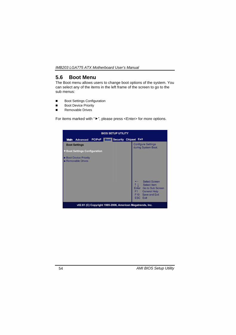
IMB203 LGA775 ATX Motherboard Userrsquos Manual
AMI BIOS Setup Utility 55
Boot Settings Configuration
Quick Boot
Enabling this item lets the BIOS skip some power on self tests (POST) The default setting is Enabled
AddOn ROM Display Mode This item selects the display mode for option ROM The default setting is Force BIOS
Boot Num-Lock Use this item to select the power-on state for the NumLock The default setting is On
PS2 Mouse Support This item determines if the BIOS should reserve IRQ12 for the PS2 mouse or allow other devices to make use of this IRQ Here are the options for your selection Auto Enabled and Disabled
Wait For lsquoF1rsquo Of Error If this item is enabled the system waits for the F1 key to be pressed when error occurs The default setting is Enabled
Hit lsquoDELrsquo Message Display If this item is enabled the system displays the message
IMB203 LGA775 ATX Motherboard Userrsquos Manual
AMI BIOS Setup Utility 56
ldquoPress DEL to run Setuprdquo during POST The default setting is Enabled
Interrupt 19 Capture If this item is enabled this function makes the option ROMs to trap Interrupt 19 The default setting is Disabled
Boot Device Priority The Boot Device Priority screen specifies the boot device priority sequence from the available devices
IMB203 LGA775 ATX Motherboard Userrsquos Manual
AMI BIOS Setup Utility 57
Removable Drives Use this screen to view the removable drives in the system The BIOS will attempt to arrange the removable drive boot sequence automatically You can also change the booting sequence
IMB203 LGA775 ATX Motherboard Userrsquos Manual
AMI BIOS Setup Utility 58
57 Security Menu The Security menu allows users to change the security settings for the system
Supervisor Password
This item indicates whether a supervisor password has been set If the password has been installed Installed displays If not Not Installed displays
User Password This item indicates whether a user password has been set If the password has been installed Installed displays If not Not Installed displays
Change Supervisor Password Select this option and press ltEntergt to access the sub menu You can use the sub menu to change the supervisor password
Change User Password Select this option and press ltEntergt to access the sub menu You can use the sub menu to change the user password
IMB203 LGA775 ATX Motherboard Userrsquos Manual
AMI BIOS Setup Utility 59
58 Chipset Menu The Chipset menu allows users to change the advanced chipset settings You can select any of the items in the left frame of the screen to go to the sub menus
North Bridge Configuration South Bridge Configuration ME Subsystem Configuration
For items marked with ldquo rdquo please press ltEntergt for more options
IMB203 LGA775 ATX Motherboard Userrsquos Manual
AMI BIOS Setup Utility 60
North Bridge Configuration
Memory Remap Feature
Use this item to enable or disable the remapping of the overlapped PCI memory above the total physical memory Only 64-bit OS supports this function
DRAM Frequency This item allows you to control the Memory Clock
Configure DRAM Timing by SPD This item can enable or disable DRAM timing by SPD (Serial Presence Detect) device which is a small EEPROM chip on the memory module containing important information about the module speed size addressing mode and various parameters
Memory Hole You can reserve this area of system memory for ISA adapter ROM When this area is reserved it cannot be cached Check the user information of peripherals that need to use this area o f system memory for the memory requirements Here are the options Disabled and 15M-16M
IMB203 LGA775 ATX Motherboard Userrsquos Manual
AMI BIOS Setup Utility 61
Initiate Graphic Adapter When using multiple graphics cards this item can select which graphics controller to be the primary display device during boot
IGD Graphics Mode Select This item allows you to select the amount of system memory used by the internal graphics device
PEG Port ConfigurationPEG Port This item is a toggle to enable or disable the PCI Express port Here are the options for your selection Auto and Disabled
Video Function Configuration Press ltEntergt for the sub-menu for setting up video function
IMB203 LGA775 ATX Motherboard Userrsquos Manual
AMI BIOS Setup Utility 62
South Bridge Configuration
GbE Wake Up From S5 This item specifies whether the system will be awakened from the S5 power
HDA Controller This item allows you to enable or disable the HD audio support
Restore on AC Power Loss This item can control how the PC will behave once power is restored following a power outage or other unexpected shutdown
PCIE Port Configuration This item allows you to set or disable the PCI Express Ports
IMB203 LGA775 ATX Motherboard Userrsquos Manual
AMI BIOS Setup Utility 63
ME Subsystem Configuration
It is strongly recommended that you do not modify these options unless you are an advanced user
IMB203 LGA775 ATX Motherboard Userrsquos Manual
AMI BIOS Setup Utility 64
59 Exit Menu The Exit menu allows users to load your system configuration with optimal or failsafe default values
Save Changes and Exit
When you have completed the system configuration changes select this option to leave Setup and reboot the computer so the new system configuration parameters can take effect Select Save Changes and Exit from the Exit menu and press ltEntergt Select Ok to save changes and exit
Discard Changes and Exit Select this option to quit Setup without making any permanent changes to the system configuration Select Discard Changes and Exit from the Exit menu and press ltEntergt Select Ok to discard changes and exit
Load Optimal Defaults It automatically sets all Setup options to a complete set of default settings when you select this option The Optimal settings are designed for maximum system performance but may not work best for all computer applications In particular do not use the Optimal Setup options if your
IMB203 LGA775 ATX Motherboard Userrsquos Manual
AMI BIOS Setup Utility 65
computer is experiencing system configuration problems Select Load Optimal Defaults from the Exit menu and press ltEntergt
Load Fail-Safe Defaults It automatically sets all Setup options to a complete set of default settings when you select this option The Fail-Safe settings are designed for maximum system stability but not maximum performance Select the Fail-Safe Setup options if your computer is experiencing system configuration problems Select Load Fail-Safe Defaults from the Exit menu and press ltEntergt Select Ok to load Fail-Safe defaults
IMB203 LGA775 ATX Motherboard Userrsquos Manual
AMI BIOS Setup Utility 66
MEMO
IMB203 LGA775 ATX Motherboard Userrsquos Manual
Installation of Drivers 67
CHPATER 6 INSTALLATION OF DRIVERS
The device drivers are located on the Product Information CD-ROM that comes with the IMB203 Series package The auto-run function of drivers will guide you to install the utilities and device drivers under a Windows system You can follow the onscreen instructions to install these devices
Chipse VGA LAN Audio iAMT MEI
61 Installing Chipset Driver 1 Run the SETUPEXE program from the driver directory in
your driver CD Click ldquoNextrdquo to next step
IMB203 LGA775 ATX Motherboard Userrsquos Manual
Installation of Drivers 68
2 An Intelreg License Agreement appears to show you the important information Click ldquoYesrdquo to next step
3 Refer to the Readme file below to view the system requirements and installation information
IMB203 LGA775 ATX Motherboard Userrsquos Manual
Installation of Drivers 69
3-1 Please wait while running the following setup operations
3-2 Please wait while running the following setup operations
IMB203 LGA775 ATX Motherboard Userrsquos Manual
Installation of Drivers 70
4 Click ldquoFinishrdquo to complete the setup process
5 You will be asked to reboot your computer when the installation is completed Please click ldquoYes I want to restart my computer nowrdquo if you donrsquot need to install any other drivers Otherwise please click ldquoNo I will restart my computer laterrdquo and go on next step
IMB203 LGA775 ATX Motherboard Userrsquos Manual
Installation of Drivers 71
62 Installing VGA Driver 1 Run the SETUPEXE program from the driver directory in
your driver CD Click ldquoNextrdquo to next step
2 An Intelreg License Agreement appears to show you the
important information Click ldquoYesrdquo to next step
IMB203 LGA775 ATX Motherboard Userrsquos Manual
Installation of Drivers 72
3 The message of Readme File Information appears to show you the system requirements and installation information Please click ldquoNextrdquo
4 Please wait while running the following setup operations
When this message appears please click ldquoNextrdquo
IMB203 LGA775 ATX Motherboard Userrsquos Manual
Installation of Drivers 73
5 Click ldquoFinishrdquo to complete the setup process
6 You will be asked to reboot your computer when the installation is completed Please click ldquoYes I want to restart my computer nowrdquo if you donrsquot need to install any other drivers Otherwise please click ldquoNo I will restart my computer laterrdquo and click ldquoFinishrdquo to complete the installation
IMB203 LGA775 ATX Motherboard Userrsquos Manual
Installation of Drivers 74
63 Installing LAN Driver
11 Run the InstallShield Wizard for Network Connections from
the driver directory in your driver CD Click ldquoNextrdquo to next step
IMB203 LGA775 ATX Motherboard Userrsquos Manual
Installation of Drivers 75
12 An Intelreg License Agreement appears to show you the important information Click ldquoYesrdquo to next step
13 A Setup Options window appears that you can select the
program features you want to install
IMB203 LGA775 ATX Motherboard Userrsquos Manual
Installation of Drivers 76
2 Click ldquoInstallrdquo to start the installation
3 Please wait while running the following installation operation
IMB203 LGA775 ATX Motherboard Userrsquos Manual
Installation of Drivers 77
4 Click ldquoFinishrdquo to complete the installation
Note The Driver item [Wake on Directed Packet] default is Enabled under Windows Vista
格式化 字型 (符號) Arial
格式化 字型 (符號) Arial
格式化 字型 斜體 字型色彩 黑色 (符號) Arial 非加寬 緊縮
格式化 字型 斜體 字型色彩 黑色 (符號) Arial 非加寬 緊縮
格式化 字型 (符號) Arial 非加寬 緊縮
IMB203 LGA775 ATX Motherboard Userrsquos Manual
Installation of Drivers 78
64 Installing AUDIO Driver 1 Run the InstallShield Wizard for Realtek High Definition
Audio Driver from the driver directory in your driver CD Click ldquoNextrdquo to next step
IMB203 LGA775 ATX Motherboard Userrsquos Manual
Installation of Drivers 79
2 Click ldquoInstallrdquo to start the installation and wait while running the installation operation
3 Click ldquoFinishrdquo to complete the installation
IMB203 LGA775 ATX Motherboard Userrsquos Manual
Installation of Drivers 80
65 Installing iAMT (Active Management Technology) Driver
Note You must download and properly install the required NET version 35 provided from a separate downloading of the actual FimwareTools kit releases posted on VIP prior to loading the MEILMS Driver stack
651 LMS_SOL Setup
1 Run the setup program to install Intelreg Active Management Technology onto your computer It is strongly recommended that you exit all programs before continuing Click ldquoNextrdquo to next step
格式化 字型 (符號) Arial
格式化 字型 (符號) Arial 非加寬 緊縮
IMB203 LGA775 ATX Motherboard Userrsquos Manual
Installation of Drivers 81
2 An Intelreg license agreement appears that you need to continue the setup program by clicking ldquoYesrdquo to accept the terms
IMB203 LGA775 ATX Motherboard Userrsquos Manual
Installation of Drivers 82
3 Refer to the Readme file below to view the system requirements and installation information Click ldquoNextrdquo to next setup
4 Please wait while running the following installation operation
IMB203 LGA775 ATX Motherboard Userrsquos Manual
Installation of Drivers 83
5 Click ldquoFinishrdquo to complete the installation
IMB203 LGA775 ATX Motherboard Userrsquos Manual
Installation of Drivers 84
652 LMS_SOL_IS Setup
1 Run the setup program to install Intelreg Active Management Technology onto your computer It is strongly recommended that you exit all programs before continuing Click ldquoNextrdquo to next step
IMB203 LGA775 ATX Motherboard Userrsquos Manual
Installation of Drivers 85
2 An Intelreg license agreement appears that you need to continue the setup program by clicking ldquoYesrdquo to accept the terms
IMB203 LGA775 ATX Motherboard Userrsquos Manual
Installation of Drivers 86
3 Refer to the Readme file below to view the system requirements and installation information Click ldquoNextrdquo to next setup
4 Please wait while running the following installation operation
IMB203 LGA775 ATX Motherboard Userrsquos Manual
Installation of Drivers 87
5 Click ldquoFinishrdquo to complete the installation
IMB203 LGA775 ATX Motherboard Userrsquos Manual
Installation of Drivers 88
66 Installing MEI (Management Engine Interface) Driver
Note You must download and properly install the required NET version 35 provided from a separate downloading of the actual FimwareTools kit releases posted on VIP prior to loading the MEILMS Driver stack
1 Run the setup program to install Intelreg Management Engine
Interface onto your computer It is strongly recommended that you exit all programs before continuing Click ldquoNextrdquo to next step
格式化 字型 (符號) Arial
格式化 字型 (符號) Arial 非加寬 緊縮
IMB203 LGA775 ATX Motherboard Userrsquos Manual
Installation of Drivers 89
2 An Intelreg license agreement appears that you need to continue the setup program by clicking ldquoYesrdquo to accept the terms
IMB203 LGA775 ATX Motherboard Userrsquos Manual
Installation of Drivers 90
3 Refer to the Readme file below to view the system requirements and installation information Click ldquoNextrdquo to next setup
4 Please wait while running the following installation operation
IMB203 LGA775 ATX Motherboard Userrsquos Manual
Installation of Drivers 91
5 Click ldquoFinishrdquo to complete the installation
IMB203 LGA775 ATX Motherboard Userrsquos Manual
Installation of Drivers 92
MEMO
IMB203 LGA775 ATX Motherboard Userrsquos Manual
Watchdog Timer 93
APPENDIX A WATCHDOG TIMER
Watchdog Timer Setting After the system stops working for a while it can be auto-reset by the Watchdog Timer The integrated Watchdog Timer can be set up in the system reset mode by program
Using the Watchdog Function Start darr Un-Lock WDT O 2E 87 Un-lock super IO
O 2E 87 Un-lock super IO darr Set WDT Function O 2E 2D O 2F 20 Select Logic device O 2E 07 O 2F 08 darr Activate WDT O 2E 30
O 2F 01 Set Second or Minute O 2E F5
O 2F N N=00 or 08(See below table) darr Set base timer O 2E F6
O 2F M=000102hellipFF(Hex) Value=0 to 255 darr WDT counting
re-set timer O 2E F6
O 2F M M=000102hellipFF(See below table) darr
格式化
格式化 項目符號及編號
格式化 項目符號及編號
格式化 字型 8 點 字型色彩黑色
格式化 字型 8 點 字型色彩黑色
格式化 定位點 1257 字元左 + 不在 1012 字元 + 1386字元
格式化 字型 8 點 字型色彩黑色
格式化 定位點 1257 字元左 + 不在 134 字元 + 1362字元
格式化 字型色彩 黑色
格式化 字型色彩 黑色
刪除
IMB203 LGA775 ATX Motherboard Userrsquos Manual
Watchdog Timer 94
IF No re-set timer WDT time-out generate RESET IF to disable WDT O 2E 30
O 2F 00 Can be disable at any time
N=00
M= 00h Time-out Disable 01h Time-out occurs after 1 second 02h Time-out occurs after 2 second 03h Time-out occurs after 3 second helliphelliphelliphelliphelliphelliphelliphelliphellip FFh Time-out occurs after 255 second
N=08
M= 00h Time-out Disable 01h Time-out occurs after 1 minute 02h Time-out occurs after 2 minutes 03h Time-out occurs after 3 minutes helliphelliphelliphelliphelliphelliphelliphelliphellip
FFh Time-out occurs after 255 minutes
格式化 字型色彩 黑色
格式化 字型色彩 黑色
IMB203 LGA775 ATX Motherboard Userrsquos Manual
PCI IRQ Routing 95
APPENDIX B PCI IRQ ROUTING
PICMG PCI IRQ Routing
Device ID Slot Int
PCI Slot 0 31 0 BCDA PCI Slot 1 30 1 CDAB PCI Slot 2 29 2 DABC PCI Slot 3 28 3 ABCD
IMB203 LGA775 ATX Motherboard Userrsquos Manual
PCI IRQ Routing 96
MEMO
IMB203 LGA775 ATX Motherboard Userrsquos Manual
Configuring SATA for RAID Function 97
APPENDIX C CONFIGURING SATA FOR RAID
FUNCTION
Configuring SATA Hard Drive(s) for RAID Function (Controller IntelregICH10DODO DH only) Please follow up the steps below to configure SATA hard drive(s) (1) Install SATA hard drive(s) in your system (2) Enter the BIOS Setup to configure SATA controller mode and boot
sequence (3) Configure RAID by the RAID BIOS (4) Install the SATA controller driver during the OS installation Before you begin the SATA configuration please prepare (a) Two SATA hard drives (to ensure optimal performance it is
recommended that you use two hard drives with identical model and capacity) If you do not want to create RAID with the SATA controller you may prepare only one hard drive
(b) An empty formatted floppy disk (c) Windows XP setup disk (1) Installing SATA hard drive(s) in your system
Connect one end of the SATA signal cable to the rear of the SATA hard drive and the other end to available SATA port(s) on the board Then connect the power connector of power supply to the hard drive
(2) Configuring SATA controller mode and boot sequence by the BIOS Setup You have to make sure whether the SATA controller is configured correctly by system BIOS Setup and set up BIOS boot sequence for the SATA hard drive(s)
IMB203 LGA775 ATX Motherboard Userrsquos Manual
Configuring SATA for RAID Function 98
(2)-1-1 Turn on your system and then press the Del button to enter BIOS Setup during running POST (Power-On Self Test) If you want to create RAID just go to the Advanced Settings menuIDE configuration select the Configure SATA1 as and press ltEntergt for more options
IMB203 LGA775 ATX Motherboard Userrsquos Manual
Configuring SATA for RAID Function 99
(2)-1-2 A list of options appears please select RAID
IMB203 LGA775 ATX Motherboard Userrsquos Manual
Configuring SATA for RAID Function 100
(2)-2 Set CDROM for First Boot Device under the Boot Settings menu to boot CD-ROM after system restarts
(2)-3 Save and exit the BIOS Setup
IMB203 LGA775 ATX Motherboard Userrsquos Manual
Configuring SATA for RAID Function 101
(3) Configuring RAID by the RAID BIOS Enter the RAID BIOS setup utility to configure a RAID array Skip this step and proceed to Section 4 if you do not want to create a RAID (3)-1 After the POST memory testing and before the operating
system booting a message Press ltCtrl-Igt to enter Configuration Utility shows up accordingly press ltCTRL+ Igt to enter the RAID BIOS setup utility
(3)-2 After you press ltCTRL+ Igt the Create RAID Volume screen will appear If you want to create a RAID array select the Create RAID Volume option in the Main Menu and press ENTER
IMB203 LGA775 ATX Motherboard Userrsquos Manual
Configuring SATA for RAID Function 102
(3)-3-1 After entering the CREATE VOLUME MENU screen you can type the disk array name with 1~16 letters (letters cannot be special characters) in the item ldquoNamerdquo
(3)-3-2 When finished press ENTER to select a RAID level There are three RAID levels RAID0 RAID1 and RAID5 amp RAID10 Select a RAID level and press ENTER
IMB203 LGA775 ATX Motherboard Userrsquos Manual
Configuring SATA for RAID Function 103
(3)-4 Set the stripe block size The KB is the standard unit of stripe block size The stripe block size can be 4KB to 128KB After the setting press ENTER for the array capacity
(3)-5 After setting all the items on the menu select Create Volume
and press ENTER to start creating the RAID array
IMB203 LGA775 ATX Motherboard Userrsquos Manual
Configuring SATA for RAID Function 104
(3)-6 When prompting the confirmation press ldquoYldquo to create this volume or ldquoNldquo to cancel the creation
After the creation is completed you can see detailed information about the RAID Array in the DISKVOLUME INFORMATION section including RAID mode disk block size disk name and disk capacity etc
IMB203 LGA775 ATX Motherboard Userrsquos Manual
Configuring SATA for RAID Function 105
Delete RAID Volume If you want to delete a RAID volume select the Delete RAID Volume option in Main Menu Press ENTER and follow on-screen instructions
Please press [ESC] to exit the RAID BIOS utility Now you can proceed to install a SATA driver controller and the operating system
IMB203 LGA775 ATX Motherboard Userrsquos Manual
Configuring SATA for RAID Function 106
(4) Making a SATA Driver Disk To install the operating system onto a serial ATA hard disk successfully you need to install the SATA controller driver during the OS installation Without the driver the hard disk may not be recognized during the Windows setup process First of all please format a blank floppy disk Secondly follow up these steps below to produce a SATA driver disk Users can insert the Driver CD and the formatted blank floppy disk in another system And then please copy all of file of the f6flpy32 folder in the Driver CD to a floppy disk Note Please copy all of file of the f6flpy64 folder if installing 64-bit
Windows Operating System
IMB203 LGA775 ATX Motherboard Userrsquos Manual
Configuring SATA for RAID Function 107
(5) Installing the SATA controller driver during the OS installation Now the SATA driver disk is ready and BIOS settings configured you can proceed to install Windows 2000XP onto your SATA hard drive using the SATA driver Here is an example for Windows XP installation (5)-1 Restart your system to boot the Windows 2000XP Setup disk
and press F6 button as soon as you see the message Press F6 if you need to install a 3rd party SCSI or RAID driver After pressing the F6 button there will be a few moments for some files being loaded before next screen appears
IMB203 LGA775 ATX Motherboard Userrsquos Manual
Configuring SATA for RAID Function 108
(5)-2 When you see the screen below insert the floppy disk containing the SATA driver and press ldquoSrdquo
(5)-3 If the Setup correctly recognizes the driver of the floppy disk
a controller menu will appear below Use the ARROW keys to select Intel(R) ICH8RICH9RICH10RDO SATA RAID Controller and press ENTER Then it will begin to load the SATA driver from the floppy disk
IMB203 LGA775 ATX Motherboard Userrsquos Manual
Configuring SATA for RAID Function 109
Note If a message on the screen saying that one or some file(s) cannot be found please check the floppy disk or copy the correct SATA driver again from the driver CD
IMB203 LGA775 ATX Motherboard Userrsquos Manual
Configuring SATA for RAID Function 110
MEMO
IMB203 LGA775 ATX Motherboard Userrsquos Manual
iAMT Settings 111
APPENDIX D iAMT SETTINGS
The Intelreg Active Management Technology (Intelreg iAMT) has decreased a major barrier to IT efficiency that uses built-in platform capabilities and popular third-party management and security applications to allow IT a better discovering healing and protection their networked computing assets In order to utilize Intel iAMT you must enter the ME BIOS (CTRL + P during system startup) change the ME BIOS password and then select ldquoIntelreg iAMTrdquo as the manageability feature
D1 Entering MEBx 1 You must go to BIOS TO start iAMT function 2 Exit from BIOS after starting iAMT and press Ctrl+P to enter MEBx Setting
It is better to press Ctrl+P before the screen popping out
格式化
IMB203 LGA775 ATX Motherboard Userrsquos Manual
iAMT Settings 112
D2 Set amp Change Password 1 You will be asked to set a password when first log in The default
password is lsquoadminrsquo
2 You will be asked to change the password before setting ME
Change Password
IMB203 LGA775 ATX Motherboard Userrsquos Manual
iAMT Settings 113
3 You must confirm your new password while revising (as Remark 1)
Remark 1 The new password must contain (example 11qqQQ) (default value)
Eight characters
One upper case
One lower case
One number
One special symbol such as $ or
( excepted)
Underline ( _ ) and space are valid characters for password but they wonrsquot make higher complexity
IMB203 LGA775 ATX Motherboard Userrsquos Manual
iAMT Settings 114
D3 Intelreg iAMT Settings 1 Select Intelreg iAMT Configuration and press ltENTERgt
2 Key in the Host Name If Intelreg iAMT set to lsquoDHCPlsquo the Host name must be identical to the operating system mechanic
IMB203 LGA775 ATX Motherboard Userrsquos Manual
iAMT Settings 115
3 Select TCPIP to get into Network interface and set it to lsquoENABLEDrsquo into DHCP Mode and set it to lsquoDISABLEDrsquo (as Remark 2) into Domain name and set the Intel Management Engine domain name such as lsquoAMTintelcomrsquo
(3-1)
(3-2)
IMB203 LGA775 ATX Motherboard Userrsquos Manual
iAMT Settings 116
Remark 2 DHCP Mode lsquoDISABLEDlsquo if DHCP Mode is disabled you can make the following settings
IP address
Subnet mask
IMB203 LGA775 ATX Motherboard Userrsquos Manual
iAMT Settings 117
Default Gateway address
Preferred DNS address
IMB203 LGA775 ATX Motherboard Userrsquos Manual
iAMT Settings 118
Alternate DNS address
Domain name
4 Exit from MEBx after completing the iAMT settings
IMB203 LGA775 ATX Motherboard Userrsquos Manual
iAMT Settings 119
D4 iAMT Web Console 1 From a web browser please type http(IP ADDRESS)16992
which connects to iAMT Web Example http1014021416992
2 To log on you will be required to type in username and password
for access to the Web
USER admin (default value)
PASS (MEBx password)
IMB203 LGA775 ATX Motherboard Userrsquos Manual
iAMT Settings 120
3 Enter the iAMT Web
4 Click Remote Control and select commands on the right side
IMB203 LGA775 ATX Motherboard Userrsquos Manual
iAMT Settings 121
5 When you have finished using the iAMT Web console close the Web browser
IMB203 LGA775 ATX Motherboard Userrsquos Manual
iAMT Settings 122
MEMO
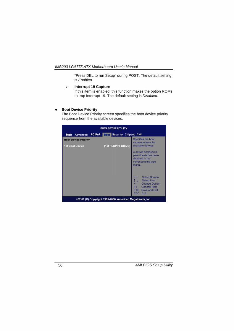
IMB203 LGA775 ATX Motherboard Userrsquos Manual
AMI BIOS Setup Utility 56
ldquoPress DEL to run Setuprdquo during POST The default setting is Enabled
Interrupt 19 Capture If this item is enabled this function makes the option ROMs to trap Interrupt 19 The default setting is Disabled
Boot Device Priority The Boot Device Priority screen specifies the boot device priority sequence from the available devices
IMB203 LGA775 ATX Motherboard Userrsquos Manual
AMI BIOS Setup Utility 57
Removable Drives Use this screen to view the removable drives in the system The BIOS will attempt to arrange the removable drive boot sequence automatically You can also change the booting sequence
IMB203 LGA775 ATX Motherboard Userrsquos Manual
AMI BIOS Setup Utility 58
57 Security Menu The Security menu allows users to change the security settings for the system
Supervisor Password
This item indicates whether a supervisor password has been set If the password has been installed Installed displays If not Not Installed displays
User Password This item indicates whether a user password has been set If the password has been installed Installed displays If not Not Installed displays
Change Supervisor Password Select this option and press ltEntergt to access the sub menu You can use the sub menu to change the supervisor password
Change User Password Select this option and press ltEntergt to access the sub menu You can use the sub menu to change the user password
IMB203 LGA775 ATX Motherboard Userrsquos Manual
AMI BIOS Setup Utility 59
58 Chipset Menu The Chipset menu allows users to change the advanced chipset settings You can select any of the items in the left frame of the screen to go to the sub menus
North Bridge Configuration South Bridge Configuration ME Subsystem Configuration
For items marked with ldquo rdquo please press ltEntergt for more options
IMB203 LGA775 ATX Motherboard Userrsquos Manual
AMI BIOS Setup Utility 60
North Bridge Configuration
Memory Remap Feature
Use this item to enable or disable the remapping of the overlapped PCI memory above the total physical memory Only 64-bit OS supports this function
DRAM Frequency This item allows you to control the Memory Clock
Configure DRAM Timing by SPD This item can enable or disable DRAM timing by SPD (Serial Presence Detect) device which is a small EEPROM chip on the memory module containing important information about the module speed size addressing mode and various parameters
Memory Hole You can reserve this area of system memory for ISA adapter ROM When this area is reserved it cannot be cached Check the user information of peripherals that need to use this area o f system memory for the memory requirements Here are the options Disabled and 15M-16M
IMB203 LGA775 ATX Motherboard Userrsquos Manual
AMI BIOS Setup Utility 61
Initiate Graphic Adapter When using multiple graphics cards this item can select which graphics controller to be the primary display device during boot
IGD Graphics Mode Select This item allows you to select the amount of system memory used by the internal graphics device
PEG Port ConfigurationPEG Port This item is a toggle to enable or disable the PCI Express port Here are the options for your selection Auto and Disabled
Video Function Configuration Press ltEntergt for the sub-menu for setting up video function
IMB203 LGA775 ATX Motherboard Userrsquos Manual
AMI BIOS Setup Utility 62
South Bridge Configuration
GbE Wake Up From S5 This item specifies whether the system will be awakened from the S5 power
HDA Controller This item allows you to enable or disable the HD audio support
Restore on AC Power Loss This item can control how the PC will behave once power is restored following a power outage or other unexpected shutdown
PCIE Port Configuration This item allows you to set or disable the PCI Express Ports
IMB203 LGA775 ATX Motherboard Userrsquos Manual
AMI BIOS Setup Utility 63
ME Subsystem Configuration
It is strongly recommended that you do not modify these options unless you are an advanced user
IMB203 LGA775 ATX Motherboard Userrsquos Manual
AMI BIOS Setup Utility 64
59 Exit Menu The Exit menu allows users to load your system configuration with optimal or failsafe default values
Save Changes and Exit
When you have completed the system configuration changes select this option to leave Setup and reboot the computer so the new system configuration parameters can take effect Select Save Changes and Exit from the Exit menu and press ltEntergt Select Ok to save changes and exit
Discard Changes and Exit Select this option to quit Setup without making any permanent changes to the system configuration Select Discard Changes and Exit from the Exit menu and press ltEntergt Select Ok to discard changes and exit
Load Optimal Defaults It automatically sets all Setup options to a complete set of default settings when you select this option The Optimal settings are designed for maximum system performance but may not work best for all computer applications In particular do not use the Optimal Setup options if your
IMB203 LGA775 ATX Motherboard Userrsquos Manual
AMI BIOS Setup Utility 65
computer is experiencing system configuration problems Select Load Optimal Defaults from the Exit menu and press ltEntergt
Load Fail-Safe Defaults It automatically sets all Setup options to a complete set of default settings when you select this option The Fail-Safe settings are designed for maximum system stability but not maximum performance Select the Fail-Safe Setup options if your computer is experiencing system configuration problems Select Load Fail-Safe Defaults from the Exit menu and press ltEntergt Select Ok to load Fail-Safe defaults
IMB203 LGA775 ATX Motherboard Userrsquos Manual
AMI BIOS Setup Utility 66
MEMO
IMB203 LGA775 ATX Motherboard Userrsquos Manual
Installation of Drivers 67
CHPATER 6 INSTALLATION OF DRIVERS
The device drivers are located on the Product Information CD-ROM that comes with the IMB203 Series package The auto-run function of drivers will guide you to install the utilities and device drivers under a Windows system You can follow the onscreen instructions to install these devices
Chipse VGA LAN Audio iAMT MEI
61 Installing Chipset Driver 1 Run the SETUPEXE program from the driver directory in
your driver CD Click ldquoNextrdquo to next step
IMB203 LGA775 ATX Motherboard Userrsquos Manual
Installation of Drivers 68
2 An Intelreg License Agreement appears to show you the important information Click ldquoYesrdquo to next step
3 Refer to the Readme file below to view the system requirements and installation information
IMB203 LGA775 ATX Motherboard Userrsquos Manual
Installation of Drivers 69
3-1 Please wait while running the following setup operations
3-2 Please wait while running the following setup operations
IMB203 LGA775 ATX Motherboard Userrsquos Manual
Installation of Drivers 70
4 Click ldquoFinishrdquo to complete the setup process
5 You will be asked to reboot your computer when the installation is completed Please click ldquoYes I want to restart my computer nowrdquo if you donrsquot need to install any other drivers Otherwise please click ldquoNo I will restart my computer laterrdquo and go on next step
IMB203 LGA775 ATX Motherboard Userrsquos Manual
Installation of Drivers 71
62 Installing VGA Driver 1 Run the SETUPEXE program from the driver directory in
your driver CD Click ldquoNextrdquo to next step
2 An Intelreg License Agreement appears to show you the
important information Click ldquoYesrdquo to next step
IMB203 LGA775 ATX Motherboard Userrsquos Manual
Installation of Drivers 72
3 The message of Readme File Information appears to show you the system requirements and installation information Please click ldquoNextrdquo
4 Please wait while running the following setup operations
When this message appears please click ldquoNextrdquo
IMB203 LGA775 ATX Motherboard Userrsquos Manual
Installation of Drivers 73
5 Click ldquoFinishrdquo to complete the setup process
6 You will be asked to reboot your computer when the installation is completed Please click ldquoYes I want to restart my computer nowrdquo if you donrsquot need to install any other drivers Otherwise please click ldquoNo I will restart my computer laterrdquo and click ldquoFinishrdquo to complete the installation
IMB203 LGA775 ATX Motherboard Userrsquos Manual
Installation of Drivers 74
63 Installing LAN Driver
11 Run the InstallShield Wizard for Network Connections from
the driver directory in your driver CD Click ldquoNextrdquo to next step
IMB203 LGA775 ATX Motherboard Userrsquos Manual
Installation of Drivers 75
12 An Intelreg License Agreement appears to show you the important information Click ldquoYesrdquo to next step
13 A Setup Options window appears that you can select the
program features you want to install
IMB203 LGA775 ATX Motherboard Userrsquos Manual
Installation of Drivers 76
2 Click ldquoInstallrdquo to start the installation
3 Please wait while running the following installation operation
IMB203 LGA775 ATX Motherboard Userrsquos Manual
Installation of Drivers 77
4 Click ldquoFinishrdquo to complete the installation
Note The Driver item [Wake on Directed Packet] default is Enabled under Windows Vista
格式化 字型 (符號) Arial
格式化 字型 (符號) Arial
格式化 字型 斜體 字型色彩 黑色 (符號) Arial 非加寬 緊縮
格式化 字型 斜體 字型色彩 黑色 (符號) Arial 非加寬 緊縮
格式化 字型 (符號) Arial 非加寬 緊縮
IMB203 LGA775 ATX Motherboard Userrsquos Manual
Installation of Drivers 78
64 Installing AUDIO Driver 1 Run the InstallShield Wizard for Realtek High Definition
Audio Driver from the driver directory in your driver CD Click ldquoNextrdquo to next step
IMB203 LGA775 ATX Motherboard Userrsquos Manual
Installation of Drivers 79
2 Click ldquoInstallrdquo to start the installation and wait while running the installation operation
3 Click ldquoFinishrdquo to complete the installation
IMB203 LGA775 ATX Motherboard Userrsquos Manual
Installation of Drivers 80
65 Installing iAMT (Active Management Technology) Driver
Note You must download and properly install the required NET version 35 provided from a separate downloading of the actual FimwareTools kit releases posted on VIP prior to loading the MEILMS Driver stack
651 LMS_SOL Setup
1 Run the setup program to install Intelreg Active Management Technology onto your computer It is strongly recommended that you exit all programs before continuing Click ldquoNextrdquo to next step
格式化 字型 (符號) Arial
格式化 字型 (符號) Arial 非加寬 緊縮
IMB203 LGA775 ATX Motherboard Userrsquos Manual
Installation of Drivers 81
2 An Intelreg license agreement appears that you need to continue the setup program by clicking ldquoYesrdquo to accept the terms
IMB203 LGA775 ATX Motherboard Userrsquos Manual
Installation of Drivers 82
3 Refer to the Readme file below to view the system requirements and installation information Click ldquoNextrdquo to next setup
4 Please wait while running the following installation operation
IMB203 LGA775 ATX Motherboard Userrsquos Manual
Installation of Drivers 83
5 Click ldquoFinishrdquo to complete the installation
IMB203 LGA775 ATX Motherboard Userrsquos Manual
Installation of Drivers 84
652 LMS_SOL_IS Setup
1 Run the setup program to install Intelreg Active Management Technology onto your computer It is strongly recommended that you exit all programs before continuing Click ldquoNextrdquo to next step
IMB203 LGA775 ATX Motherboard Userrsquos Manual
Installation of Drivers 85
2 An Intelreg license agreement appears that you need to continue the setup program by clicking ldquoYesrdquo to accept the terms
IMB203 LGA775 ATX Motherboard Userrsquos Manual
Installation of Drivers 86
3 Refer to the Readme file below to view the system requirements and installation information Click ldquoNextrdquo to next setup
4 Please wait while running the following installation operation
IMB203 LGA775 ATX Motherboard Userrsquos Manual
Installation of Drivers 87
5 Click ldquoFinishrdquo to complete the installation
IMB203 LGA775 ATX Motherboard Userrsquos Manual
Installation of Drivers 88
66 Installing MEI (Management Engine Interface) Driver
Note You must download and properly install the required NET version 35 provided from a separate downloading of the actual FimwareTools kit releases posted on VIP prior to loading the MEILMS Driver stack
1 Run the setup program to install Intelreg Management Engine
Interface onto your computer It is strongly recommended that you exit all programs before continuing Click ldquoNextrdquo to next step
格式化 字型 (符號) Arial
格式化 字型 (符號) Arial 非加寬 緊縮
IMB203 LGA775 ATX Motherboard Userrsquos Manual
Installation of Drivers 89
2 An Intelreg license agreement appears that you need to continue the setup program by clicking ldquoYesrdquo to accept the terms
IMB203 LGA775 ATX Motherboard Userrsquos Manual
Installation of Drivers 90
3 Refer to the Readme file below to view the system requirements and installation information Click ldquoNextrdquo to next setup
4 Please wait while running the following installation operation
IMB203 LGA775 ATX Motherboard Userrsquos Manual
Installation of Drivers 91
5 Click ldquoFinishrdquo to complete the installation
IMB203 LGA775 ATX Motherboard Userrsquos Manual
Installation of Drivers 92
MEMO
IMB203 LGA775 ATX Motherboard Userrsquos Manual
Watchdog Timer 93
APPENDIX A WATCHDOG TIMER
Watchdog Timer Setting After the system stops working for a while it can be auto-reset by the Watchdog Timer The integrated Watchdog Timer can be set up in the system reset mode by program
Using the Watchdog Function Start darr Un-Lock WDT O 2E 87 Un-lock super IO
O 2E 87 Un-lock super IO darr Set WDT Function O 2E 2D O 2F 20 Select Logic device O 2E 07 O 2F 08 darr Activate WDT O 2E 30
O 2F 01 Set Second or Minute O 2E F5
O 2F N N=00 or 08(See below table) darr Set base timer O 2E F6
O 2F M=000102hellipFF(Hex) Value=0 to 255 darr WDT counting
re-set timer O 2E F6
O 2F M M=000102hellipFF(See below table) darr
格式化
格式化 項目符號及編號
格式化 項目符號及編號
格式化 字型 8 點 字型色彩黑色
格式化 字型 8 點 字型色彩黑色
格式化 定位點 1257 字元左 + 不在 1012 字元 + 1386字元
格式化 字型 8 點 字型色彩黑色
格式化 定位點 1257 字元左 + 不在 134 字元 + 1362字元
格式化 字型色彩 黑色
格式化 字型色彩 黑色
刪除
IMB203 LGA775 ATX Motherboard Userrsquos Manual
Watchdog Timer 94
IF No re-set timer WDT time-out generate RESET IF to disable WDT O 2E 30
O 2F 00 Can be disable at any time
N=00
M= 00h Time-out Disable 01h Time-out occurs after 1 second 02h Time-out occurs after 2 second 03h Time-out occurs after 3 second helliphelliphelliphelliphelliphelliphelliphelliphellip FFh Time-out occurs after 255 second
N=08
M= 00h Time-out Disable 01h Time-out occurs after 1 minute 02h Time-out occurs after 2 minutes 03h Time-out occurs after 3 minutes helliphelliphelliphelliphelliphelliphelliphelliphellip
FFh Time-out occurs after 255 minutes
格式化 字型色彩 黑色
格式化 字型色彩 黑色
IMB203 LGA775 ATX Motherboard Userrsquos Manual
PCI IRQ Routing 95
APPENDIX B PCI IRQ ROUTING
PICMG PCI IRQ Routing
Device ID Slot Int
PCI Slot 0 31 0 BCDA PCI Slot 1 30 1 CDAB PCI Slot 2 29 2 DABC PCI Slot 3 28 3 ABCD
IMB203 LGA775 ATX Motherboard Userrsquos Manual
PCI IRQ Routing 96
MEMO
IMB203 LGA775 ATX Motherboard Userrsquos Manual
Configuring SATA for RAID Function 97
APPENDIX C CONFIGURING SATA FOR RAID
FUNCTION
Configuring SATA Hard Drive(s) for RAID Function (Controller IntelregICH10DODO DH only) Please follow up the steps below to configure SATA hard drive(s) (1) Install SATA hard drive(s) in your system (2) Enter the BIOS Setup to configure SATA controller mode and boot
sequence (3) Configure RAID by the RAID BIOS (4) Install the SATA controller driver during the OS installation Before you begin the SATA configuration please prepare (a) Two SATA hard drives (to ensure optimal performance it is
recommended that you use two hard drives with identical model and capacity) If you do not want to create RAID with the SATA controller you may prepare only one hard drive
(b) An empty formatted floppy disk (c) Windows XP setup disk (1) Installing SATA hard drive(s) in your system
Connect one end of the SATA signal cable to the rear of the SATA hard drive and the other end to available SATA port(s) on the board Then connect the power connector of power supply to the hard drive
(2) Configuring SATA controller mode and boot sequence by the BIOS Setup You have to make sure whether the SATA controller is configured correctly by system BIOS Setup and set up BIOS boot sequence for the SATA hard drive(s)
IMB203 LGA775 ATX Motherboard Userrsquos Manual
Configuring SATA for RAID Function 98
(2)-1-1 Turn on your system and then press the Del button to enter BIOS Setup during running POST (Power-On Self Test) If you want to create RAID just go to the Advanced Settings menuIDE configuration select the Configure SATA1 as and press ltEntergt for more options
IMB203 LGA775 ATX Motherboard Userrsquos Manual
Configuring SATA for RAID Function 99
(2)-1-2 A list of options appears please select RAID
IMB203 LGA775 ATX Motherboard Userrsquos Manual
Configuring SATA for RAID Function 100
(2)-2 Set CDROM for First Boot Device under the Boot Settings menu to boot CD-ROM after system restarts
(2)-3 Save and exit the BIOS Setup
IMB203 LGA775 ATX Motherboard Userrsquos Manual
Configuring SATA for RAID Function 101
(3) Configuring RAID by the RAID BIOS Enter the RAID BIOS setup utility to configure a RAID array Skip this step and proceed to Section 4 if you do not want to create a RAID (3)-1 After the POST memory testing and before the operating
system booting a message Press ltCtrl-Igt to enter Configuration Utility shows up accordingly press ltCTRL+ Igt to enter the RAID BIOS setup utility
(3)-2 After you press ltCTRL+ Igt the Create RAID Volume screen will appear If you want to create a RAID array select the Create RAID Volume option in the Main Menu and press ENTER
IMB203 LGA775 ATX Motherboard Userrsquos Manual
Configuring SATA for RAID Function 102
(3)-3-1 After entering the CREATE VOLUME MENU screen you can type the disk array name with 1~16 letters (letters cannot be special characters) in the item ldquoNamerdquo
(3)-3-2 When finished press ENTER to select a RAID level There are three RAID levels RAID0 RAID1 and RAID5 amp RAID10 Select a RAID level and press ENTER
IMB203 LGA775 ATX Motherboard Userrsquos Manual
Configuring SATA for RAID Function 103
(3)-4 Set the stripe block size The KB is the standard unit of stripe block size The stripe block size can be 4KB to 128KB After the setting press ENTER for the array capacity
(3)-5 After setting all the items on the menu select Create Volume
and press ENTER to start creating the RAID array
IMB203 LGA775 ATX Motherboard Userrsquos Manual
Configuring SATA for RAID Function 104
(3)-6 When prompting the confirmation press ldquoYldquo to create this volume or ldquoNldquo to cancel the creation
After the creation is completed you can see detailed information about the RAID Array in the DISKVOLUME INFORMATION section including RAID mode disk block size disk name and disk capacity etc
IMB203 LGA775 ATX Motherboard Userrsquos Manual
Configuring SATA for RAID Function 105
Delete RAID Volume If you want to delete a RAID volume select the Delete RAID Volume option in Main Menu Press ENTER and follow on-screen instructions
Please press [ESC] to exit the RAID BIOS utility Now you can proceed to install a SATA driver controller and the operating system
IMB203 LGA775 ATX Motherboard Userrsquos Manual
Configuring SATA for RAID Function 106
(4) Making a SATA Driver Disk To install the operating system onto a serial ATA hard disk successfully you need to install the SATA controller driver during the OS installation Without the driver the hard disk may not be recognized during the Windows setup process First of all please format a blank floppy disk Secondly follow up these steps below to produce a SATA driver disk Users can insert the Driver CD and the formatted blank floppy disk in another system And then please copy all of file of the f6flpy32 folder in the Driver CD to a floppy disk Note Please copy all of file of the f6flpy64 folder if installing 64-bit
Windows Operating System
IMB203 LGA775 ATX Motherboard Userrsquos Manual
Configuring SATA for RAID Function 107
(5) Installing the SATA controller driver during the OS installation Now the SATA driver disk is ready and BIOS settings configured you can proceed to install Windows 2000XP onto your SATA hard drive using the SATA driver Here is an example for Windows XP installation (5)-1 Restart your system to boot the Windows 2000XP Setup disk
and press F6 button as soon as you see the message Press F6 if you need to install a 3rd party SCSI or RAID driver After pressing the F6 button there will be a few moments for some files being loaded before next screen appears
IMB203 LGA775 ATX Motherboard Userrsquos Manual
Configuring SATA for RAID Function 108
(5)-2 When you see the screen below insert the floppy disk containing the SATA driver and press ldquoSrdquo
(5)-3 If the Setup correctly recognizes the driver of the floppy disk
a controller menu will appear below Use the ARROW keys to select Intel(R) ICH8RICH9RICH10RDO SATA RAID Controller and press ENTER Then it will begin to load the SATA driver from the floppy disk
IMB203 LGA775 ATX Motherboard Userrsquos Manual
Configuring SATA for RAID Function 109
Note If a message on the screen saying that one or some file(s) cannot be found please check the floppy disk or copy the correct SATA driver again from the driver CD
IMB203 LGA775 ATX Motherboard Userrsquos Manual
Configuring SATA for RAID Function 110
MEMO
IMB203 LGA775 ATX Motherboard Userrsquos Manual
iAMT Settings 111
APPENDIX D iAMT SETTINGS
The Intelreg Active Management Technology (Intelreg iAMT) has decreased a major barrier to IT efficiency that uses built-in platform capabilities and popular third-party management and security applications to allow IT a better discovering healing and protection their networked computing assets In order to utilize Intel iAMT you must enter the ME BIOS (CTRL + P during system startup) change the ME BIOS password and then select ldquoIntelreg iAMTrdquo as the manageability feature
D1 Entering MEBx 1 You must go to BIOS TO start iAMT function 2 Exit from BIOS after starting iAMT and press Ctrl+P to enter MEBx Setting
It is better to press Ctrl+P before the screen popping out
格式化
IMB203 LGA775 ATX Motherboard Userrsquos Manual
iAMT Settings 112
D2 Set amp Change Password 1 You will be asked to set a password when first log in The default
password is lsquoadminrsquo
2 You will be asked to change the password before setting ME
Change Password
IMB203 LGA775 ATX Motherboard Userrsquos Manual
iAMT Settings 113
3 You must confirm your new password while revising (as Remark 1)
Remark 1 The new password must contain (example 11qqQQ) (default value)
Eight characters
One upper case
One lower case
One number
One special symbol such as $ or
( excepted)
Underline ( _ ) and space are valid characters for password but they wonrsquot make higher complexity
IMB203 LGA775 ATX Motherboard Userrsquos Manual
iAMT Settings 114
D3 Intelreg iAMT Settings 1 Select Intelreg iAMT Configuration and press ltENTERgt
2 Key in the Host Name If Intelreg iAMT set to lsquoDHCPlsquo the Host name must be identical to the operating system mechanic
IMB203 LGA775 ATX Motherboard Userrsquos Manual
iAMT Settings 115
3 Select TCPIP to get into Network interface and set it to lsquoENABLEDrsquo into DHCP Mode and set it to lsquoDISABLEDrsquo (as Remark 2) into Domain name and set the Intel Management Engine domain name such as lsquoAMTintelcomrsquo
(3-1)
(3-2)
IMB203 LGA775 ATX Motherboard Userrsquos Manual
iAMT Settings 116
Remark 2 DHCP Mode lsquoDISABLEDlsquo if DHCP Mode is disabled you can make the following settings
IP address
Subnet mask
IMB203 LGA775 ATX Motherboard Userrsquos Manual
iAMT Settings 117
Default Gateway address
Preferred DNS address
IMB203 LGA775 ATX Motherboard Userrsquos Manual
iAMT Settings 118
Alternate DNS address
Domain name
4 Exit from MEBx after completing the iAMT settings
IMB203 LGA775 ATX Motherboard Userrsquos Manual
iAMT Settings 119
D4 iAMT Web Console 1 From a web browser please type http(IP ADDRESS)16992
which connects to iAMT Web Example http1014021416992
2 To log on you will be required to type in username and password
for access to the Web
USER admin (default value)
PASS (MEBx password)
IMB203 LGA775 ATX Motherboard Userrsquos Manual
iAMT Settings 120
3 Enter the iAMT Web
4 Click Remote Control and select commands on the right side
IMB203 LGA775 ATX Motherboard Userrsquos Manual
iAMT Settings 121
5 When you have finished using the iAMT Web console close the Web browser
IMB203 LGA775 ATX Motherboard Userrsquos Manual
iAMT Settings 122
MEMO
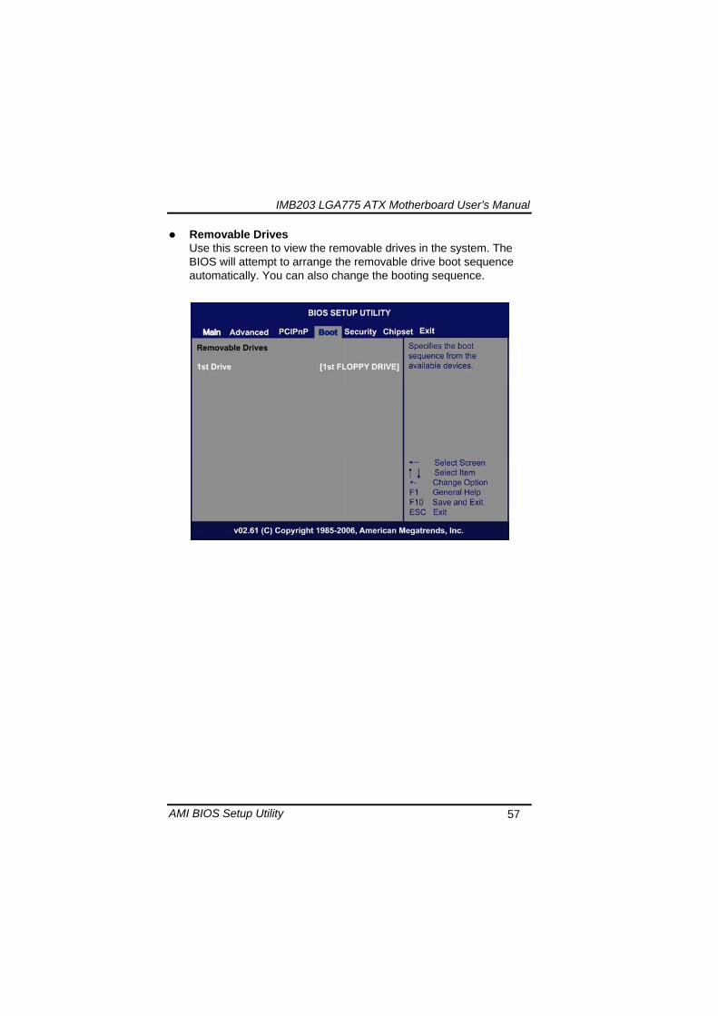
IMB203 LGA775 ATX Motherboard Userrsquos Manual
AMI BIOS Setup Utility 57
Removable Drives Use this screen to view the removable drives in the system The BIOS will attempt to arrange the removable drive boot sequence automatically You can also change the booting sequence
IMB203 LGA775 ATX Motherboard Userrsquos Manual
AMI BIOS Setup Utility 58
57 Security Menu The Security menu allows users to change the security settings for the system
Supervisor Password
This item indicates whether a supervisor password has been set If the password has been installed Installed displays If not Not Installed displays
User Password This item indicates whether a user password has been set If the password has been installed Installed displays If not Not Installed displays
Change Supervisor Password Select this option and press ltEntergt to access the sub menu You can use the sub menu to change the supervisor password
Change User Password Select this option and press ltEntergt to access the sub menu You can use the sub menu to change the user password
IMB203 LGA775 ATX Motherboard Userrsquos Manual
AMI BIOS Setup Utility 59
58 Chipset Menu The Chipset menu allows users to change the advanced chipset settings You can select any of the items in the left frame of the screen to go to the sub menus
North Bridge Configuration South Bridge Configuration ME Subsystem Configuration
For items marked with ldquo rdquo please press ltEntergt for more options
IMB203 LGA775 ATX Motherboard Userrsquos Manual
AMI BIOS Setup Utility 60
North Bridge Configuration
Memory Remap Feature
Use this item to enable or disable the remapping of the overlapped PCI memory above the total physical memory Only 64-bit OS supports this function
DRAM Frequency This item allows you to control the Memory Clock
Configure DRAM Timing by SPD This item can enable or disable DRAM timing by SPD (Serial Presence Detect) device which is a small EEPROM chip on the memory module containing important information about the module speed size addressing mode and various parameters
Memory Hole You can reserve this area of system memory for ISA adapter ROM When this area is reserved it cannot be cached Check the user information of peripherals that need to use this area o f system memory for the memory requirements Here are the options Disabled and 15M-16M
IMB203 LGA775 ATX Motherboard Userrsquos Manual
AMI BIOS Setup Utility 61
Initiate Graphic Adapter When using multiple graphics cards this item can select which graphics controller to be the primary display device during boot
IGD Graphics Mode Select This item allows you to select the amount of system memory used by the internal graphics device
PEG Port ConfigurationPEG Port This item is a toggle to enable or disable the PCI Express port Here are the options for your selection Auto and Disabled
Video Function Configuration Press ltEntergt for the sub-menu for setting up video function
IMB203 LGA775 ATX Motherboard Userrsquos Manual
AMI BIOS Setup Utility 62
South Bridge Configuration
GbE Wake Up From S5 This item specifies whether the system will be awakened from the S5 power
HDA Controller This item allows you to enable or disable the HD audio support
Restore on AC Power Loss This item can control how the PC will behave once power is restored following a power outage or other unexpected shutdown
PCIE Port Configuration This item allows you to set or disable the PCI Express Ports
IMB203 LGA775 ATX Motherboard Userrsquos Manual
AMI BIOS Setup Utility 63
ME Subsystem Configuration
It is strongly recommended that you do not modify these options unless you are an advanced user
IMB203 LGA775 ATX Motherboard Userrsquos Manual
AMI BIOS Setup Utility 64
59 Exit Menu The Exit menu allows users to load your system configuration with optimal or failsafe default values
Save Changes and Exit
When you have completed the system configuration changes select this option to leave Setup and reboot the computer so the new system configuration parameters can take effect Select Save Changes and Exit from the Exit menu and press ltEntergt Select Ok to save changes and exit
Discard Changes and Exit Select this option to quit Setup without making any permanent changes to the system configuration Select Discard Changes and Exit from the Exit menu and press ltEntergt Select Ok to discard changes and exit
Load Optimal Defaults It automatically sets all Setup options to a complete set of default settings when you select this option The Optimal settings are designed for maximum system performance but may not work best for all computer applications In particular do not use the Optimal Setup options if your
IMB203 LGA775 ATX Motherboard Userrsquos Manual
AMI BIOS Setup Utility 65
computer is experiencing system configuration problems Select Load Optimal Defaults from the Exit menu and press ltEntergt
Load Fail-Safe Defaults It automatically sets all Setup options to a complete set of default settings when you select this option The Fail-Safe settings are designed for maximum system stability but not maximum performance Select the Fail-Safe Setup options if your computer is experiencing system configuration problems Select Load Fail-Safe Defaults from the Exit menu and press ltEntergt Select Ok to load Fail-Safe defaults
IMB203 LGA775 ATX Motherboard Userrsquos Manual
AMI BIOS Setup Utility 66
MEMO
IMB203 LGA775 ATX Motherboard Userrsquos Manual
Installation of Drivers 67
CHPATER 6 INSTALLATION OF DRIVERS
The device drivers are located on the Product Information CD-ROM that comes with the IMB203 Series package The auto-run function of drivers will guide you to install the utilities and device drivers under a Windows system You can follow the onscreen instructions to install these devices
Chipse VGA LAN Audio iAMT MEI
61 Installing Chipset Driver 1 Run the SETUPEXE program from the driver directory in
your driver CD Click ldquoNextrdquo to next step
IMB203 LGA775 ATX Motherboard Userrsquos Manual
Installation of Drivers 68
2 An Intelreg License Agreement appears to show you the important information Click ldquoYesrdquo to next step
3 Refer to the Readme file below to view the system requirements and installation information
IMB203 LGA775 ATX Motherboard Userrsquos Manual
Installation of Drivers 69
3-1 Please wait while running the following setup operations
3-2 Please wait while running the following setup operations
IMB203 LGA775 ATX Motherboard Userrsquos Manual
Installation of Drivers 70
4 Click ldquoFinishrdquo to complete the setup process
5 You will be asked to reboot your computer when the installation is completed Please click ldquoYes I want to restart my computer nowrdquo if you donrsquot need to install any other drivers Otherwise please click ldquoNo I will restart my computer laterrdquo and go on next step
IMB203 LGA775 ATX Motherboard Userrsquos Manual
Installation of Drivers 71
62 Installing VGA Driver 1 Run the SETUPEXE program from the driver directory in
your driver CD Click ldquoNextrdquo to next step
2 An Intelreg License Agreement appears to show you the
important information Click ldquoYesrdquo to next step
IMB203 LGA775 ATX Motherboard Userrsquos Manual
Installation of Drivers 72
3 The message of Readme File Information appears to show you the system requirements and installation information Please click ldquoNextrdquo
4 Please wait while running the following setup operations
When this message appears please click ldquoNextrdquo
IMB203 LGA775 ATX Motherboard Userrsquos Manual
Installation of Drivers 73
5 Click ldquoFinishrdquo to complete the setup process
6 You will be asked to reboot your computer when the installation is completed Please click ldquoYes I want to restart my computer nowrdquo if you donrsquot need to install any other drivers Otherwise please click ldquoNo I will restart my computer laterrdquo and click ldquoFinishrdquo to complete the installation
IMB203 LGA775 ATX Motherboard Userrsquos Manual
Installation of Drivers 74
63 Installing LAN Driver
11 Run the InstallShield Wizard for Network Connections from
the driver directory in your driver CD Click ldquoNextrdquo to next step
IMB203 LGA775 ATX Motherboard Userrsquos Manual
Installation of Drivers 75
12 An Intelreg License Agreement appears to show you the important information Click ldquoYesrdquo to next step
13 A Setup Options window appears that you can select the
program features you want to install
IMB203 LGA775 ATX Motherboard Userrsquos Manual
Installation of Drivers 76
2 Click ldquoInstallrdquo to start the installation
3 Please wait while running the following installation operation
IMB203 LGA775 ATX Motherboard Userrsquos Manual
Installation of Drivers 77
4 Click ldquoFinishrdquo to complete the installation
Note The Driver item [Wake on Directed Packet] default is Enabled under Windows Vista
格式化 字型 (符號) Arial
格式化 字型 (符號) Arial
格式化 字型 斜體 字型色彩 黑色 (符號) Arial 非加寬 緊縮
格式化 字型 斜體 字型色彩 黑色 (符號) Arial 非加寬 緊縮
格式化 字型 (符號) Arial 非加寬 緊縮
IMB203 LGA775 ATX Motherboard Userrsquos Manual
Installation of Drivers 78
64 Installing AUDIO Driver 1 Run the InstallShield Wizard for Realtek High Definition
Audio Driver from the driver directory in your driver CD Click ldquoNextrdquo to next step
IMB203 LGA775 ATX Motherboard Userrsquos Manual
Installation of Drivers 79
2 Click ldquoInstallrdquo to start the installation and wait while running the installation operation
3 Click ldquoFinishrdquo to complete the installation
IMB203 LGA775 ATX Motherboard Userrsquos Manual
Installation of Drivers 80
65 Installing iAMT (Active Management Technology) Driver
Note You must download and properly install the required NET version 35 provided from a separate downloading of the actual FimwareTools kit releases posted on VIP prior to loading the MEILMS Driver stack
651 LMS_SOL Setup
1 Run the setup program to install Intelreg Active Management Technology onto your computer It is strongly recommended that you exit all programs before continuing Click ldquoNextrdquo to next step
格式化 字型 (符號) Arial
格式化 字型 (符號) Arial 非加寬 緊縮
IMB203 LGA775 ATX Motherboard Userrsquos Manual
Installation of Drivers 81
2 An Intelreg license agreement appears that you need to continue the setup program by clicking ldquoYesrdquo to accept the terms
IMB203 LGA775 ATX Motherboard Userrsquos Manual
Installation of Drivers 82
3 Refer to the Readme file below to view the system requirements and installation information Click ldquoNextrdquo to next setup
4 Please wait while running the following installation operation
IMB203 LGA775 ATX Motherboard Userrsquos Manual
Installation of Drivers 83
5 Click ldquoFinishrdquo to complete the installation
IMB203 LGA775 ATX Motherboard Userrsquos Manual
Installation of Drivers 84
652 LMS_SOL_IS Setup
1 Run the setup program to install Intelreg Active Management Technology onto your computer It is strongly recommended that you exit all programs before continuing Click ldquoNextrdquo to next step
IMB203 LGA775 ATX Motherboard Userrsquos Manual
Installation of Drivers 85
2 An Intelreg license agreement appears that you need to continue the setup program by clicking ldquoYesrdquo to accept the terms
IMB203 LGA775 ATX Motherboard Userrsquos Manual
Installation of Drivers 86
3 Refer to the Readme file below to view the system requirements and installation information Click ldquoNextrdquo to next setup
4 Please wait while running the following installation operation
IMB203 LGA775 ATX Motherboard Userrsquos Manual
Installation of Drivers 87
5 Click ldquoFinishrdquo to complete the installation
IMB203 LGA775 ATX Motherboard Userrsquos Manual
Installation of Drivers 88
66 Installing MEI (Management Engine Interface) Driver
Note You must download and properly install the required NET version 35 provided from a separate downloading of the actual FimwareTools kit releases posted on VIP prior to loading the MEILMS Driver stack
1 Run the setup program to install Intelreg Management Engine
Interface onto your computer It is strongly recommended that you exit all programs before continuing Click ldquoNextrdquo to next step
格式化 字型 (符號) Arial
格式化 字型 (符號) Arial 非加寬 緊縮
IMB203 LGA775 ATX Motherboard Userrsquos Manual
Installation of Drivers 89
2 An Intelreg license agreement appears that you need to continue the setup program by clicking ldquoYesrdquo to accept the terms
IMB203 LGA775 ATX Motherboard Userrsquos Manual
Installation of Drivers 90
3 Refer to the Readme file below to view the system requirements and installation information Click ldquoNextrdquo to next setup
4 Please wait while running the following installation operation
IMB203 LGA775 ATX Motherboard Userrsquos Manual
Installation of Drivers 91
5 Click ldquoFinishrdquo to complete the installation
IMB203 LGA775 ATX Motherboard Userrsquos Manual
Installation of Drivers 92
MEMO
IMB203 LGA775 ATX Motherboard Userrsquos Manual
Watchdog Timer 93
APPENDIX A WATCHDOG TIMER
Watchdog Timer Setting After the system stops working for a while it can be auto-reset by the Watchdog Timer The integrated Watchdog Timer can be set up in the system reset mode by program
Using the Watchdog Function Start darr Un-Lock WDT O 2E 87 Un-lock super IO
O 2E 87 Un-lock super IO darr Set WDT Function O 2E 2D O 2F 20 Select Logic device O 2E 07 O 2F 08 darr Activate WDT O 2E 30
O 2F 01 Set Second or Minute O 2E F5
O 2F N N=00 or 08(See below table) darr Set base timer O 2E F6
O 2F M=000102hellipFF(Hex) Value=0 to 255 darr WDT counting
re-set timer O 2E F6
O 2F M M=000102hellipFF(See below table) darr
格式化
格式化 項目符號及編號
格式化 項目符號及編號
格式化 字型 8 點 字型色彩黑色
格式化 字型 8 點 字型色彩黑色
格式化 定位點 1257 字元左 + 不在 1012 字元 + 1386字元
格式化 字型 8 點 字型色彩黑色
格式化 定位點 1257 字元左 + 不在 134 字元 + 1362字元
格式化 字型色彩 黑色
格式化 字型色彩 黑色
刪除
IMB203 LGA775 ATX Motherboard Userrsquos Manual
Watchdog Timer 94
IF No re-set timer WDT time-out generate RESET IF to disable WDT O 2E 30
O 2F 00 Can be disable at any time
N=00
M= 00h Time-out Disable 01h Time-out occurs after 1 second 02h Time-out occurs after 2 second 03h Time-out occurs after 3 second helliphelliphelliphelliphelliphelliphelliphelliphellip FFh Time-out occurs after 255 second
N=08
M= 00h Time-out Disable 01h Time-out occurs after 1 minute 02h Time-out occurs after 2 minutes 03h Time-out occurs after 3 minutes helliphelliphelliphelliphelliphelliphelliphelliphellip
FFh Time-out occurs after 255 minutes
格式化 字型色彩 黑色
格式化 字型色彩 黑色
IMB203 LGA775 ATX Motherboard Userrsquos Manual
PCI IRQ Routing 95
APPENDIX B PCI IRQ ROUTING
PICMG PCI IRQ Routing
Device ID Slot Int
PCI Slot 0 31 0 BCDA PCI Slot 1 30 1 CDAB PCI Slot 2 29 2 DABC PCI Slot 3 28 3 ABCD
IMB203 LGA775 ATX Motherboard Userrsquos Manual
PCI IRQ Routing 96
MEMO
IMB203 LGA775 ATX Motherboard Userrsquos Manual
Configuring SATA for RAID Function 97
APPENDIX C CONFIGURING SATA FOR RAID
FUNCTION
Configuring SATA Hard Drive(s) for RAID Function (Controller IntelregICH10DODO DH only) Please follow up the steps below to configure SATA hard drive(s) (1) Install SATA hard drive(s) in your system (2) Enter the BIOS Setup to configure SATA controller mode and boot
sequence (3) Configure RAID by the RAID BIOS (4) Install the SATA controller driver during the OS installation Before you begin the SATA configuration please prepare (a) Two SATA hard drives (to ensure optimal performance it is
recommended that you use two hard drives with identical model and capacity) If you do not want to create RAID with the SATA controller you may prepare only one hard drive
(b) An empty formatted floppy disk (c) Windows XP setup disk (1) Installing SATA hard drive(s) in your system
Connect one end of the SATA signal cable to the rear of the SATA hard drive and the other end to available SATA port(s) on the board Then connect the power connector of power supply to the hard drive
(2) Configuring SATA controller mode and boot sequence by the BIOS Setup You have to make sure whether the SATA controller is configured correctly by system BIOS Setup and set up BIOS boot sequence for the SATA hard drive(s)
IMB203 LGA775 ATX Motherboard Userrsquos Manual
Configuring SATA for RAID Function 98
(2)-1-1 Turn on your system and then press the Del button to enter BIOS Setup during running POST (Power-On Self Test) If you want to create RAID just go to the Advanced Settings menuIDE configuration select the Configure SATA1 as and press ltEntergt for more options
IMB203 LGA775 ATX Motherboard Userrsquos Manual
Configuring SATA for RAID Function 99
(2)-1-2 A list of options appears please select RAID
IMB203 LGA775 ATX Motherboard Userrsquos Manual
Configuring SATA for RAID Function 100
(2)-2 Set CDROM for First Boot Device under the Boot Settings menu to boot CD-ROM after system restarts
(2)-3 Save and exit the BIOS Setup
IMB203 LGA775 ATX Motherboard Userrsquos Manual
Configuring SATA for RAID Function 101
(3) Configuring RAID by the RAID BIOS Enter the RAID BIOS setup utility to configure a RAID array Skip this step and proceed to Section 4 if you do not want to create a RAID (3)-1 After the POST memory testing and before the operating
system booting a message Press ltCtrl-Igt to enter Configuration Utility shows up accordingly press ltCTRL+ Igt to enter the RAID BIOS setup utility
(3)-2 After you press ltCTRL+ Igt the Create RAID Volume screen will appear If you want to create a RAID array select the Create RAID Volume option in the Main Menu and press ENTER
IMB203 LGA775 ATX Motherboard Userrsquos Manual
Configuring SATA for RAID Function 102
(3)-3-1 After entering the CREATE VOLUME MENU screen you can type the disk array name with 1~16 letters (letters cannot be special characters) in the item ldquoNamerdquo
(3)-3-2 When finished press ENTER to select a RAID level There are three RAID levels RAID0 RAID1 and RAID5 amp RAID10 Select a RAID level and press ENTER
IMB203 LGA775 ATX Motherboard Userrsquos Manual
Configuring SATA for RAID Function 103
(3)-4 Set the stripe block size The KB is the standard unit of stripe block size The stripe block size can be 4KB to 128KB After the setting press ENTER for the array capacity
(3)-5 After setting all the items on the menu select Create Volume
and press ENTER to start creating the RAID array
IMB203 LGA775 ATX Motherboard Userrsquos Manual
Configuring SATA for RAID Function 104
(3)-6 When prompting the confirmation press ldquoYldquo to create this volume or ldquoNldquo to cancel the creation
After the creation is completed you can see detailed information about the RAID Array in the DISKVOLUME INFORMATION section including RAID mode disk block size disk name and disk capacity etc
IMB203 LGA775 ATX Motherboard Userrsquos Manual
Configuring SATA for RAID Function 105
Delete RAID Volume If you want to delete a RAID volume select the Delete RAID Volume option in Main Menu Press ENTER and follow on-screen instructions
Please press [ESC] to exit the RAID BIOS utility Now you can proceed to install a SATA driver controller and the operating system
IMB203 LGA775 ATX Motherboard Userrsquos Manual
Configuring SATA for RAID Function 106
(4) Making a SATA Driver Disk To install the operating system onto a serial ATA hard disk successfully you need to install the SATA controller driver during the OS installation Without the driver the hard disk may not be recognized during the Windows setup process First of all please format a blank floppy disk Secondly follow up these steps below to produce a SATA driver disk Users can insert the Driver CD and the formatted blank floppy disk in another system And then please copy all of file of the f6flpy32 folder in the Driver CD to a floppy disk Note Please copy all of file of the f6flpy64 folder if installing 64-bit
Windows Operating System
IMB203 LGA775 ATX Motherboard Userrsquos Manual
Configuring SATA for RAID Function 107
(5) Installing the SATA controller driver during the OS installation Now the SATA driver disk is ready and BIOS settings configured you can proceed to install Windows 2000XP onto your SATA hard drive using the SATA driver Here is an example for Windows XP installation (5)-1 Restart your system to boot the Windows 2000XP Setup disk
and press F6 button as soon as you see the message Press F6 if you need to install a 3rd party SCSI or RAID driver After pressing the F6 button there will be a few moments for some files being loaded before next screen appears
IMB203 LGA775 ATX Motherboard Userrsquos Manual
Configuring SATA for RAID Function 108
(5)-2 When you see the screen below insert the floppy disk containing the SATA driver and press ldquoSrdquo
(5)-3 If the Setup correctly recognizes the driver of the floppy disk
a controller menu will appear below Use the ARROW keys to select Intel(R) ICH8RICH9RICH10RDO SATA RAID Controller and press ENTER Then it will begin to load the SATA driver from the floppy disk
IMB203 LGA775 ATX Motherboard Userrsquos Manual
Configuring SATA for RAID Function 109
Note If a message on the screen saying that one or some file(s) cannot be found please check the floppy disk or copy the correct SATA driver again from the driver CD
IMB203 LGA775 ATX Motherboard Userrsquos Manual
Configuring SATA for RAID Function 110
MEMO
IMB203 LGA775 ATX Motherboard Userrsquos Manual
iAMT Settings 111
APPENDIX D iAMT SETTINGS
The Intelreg Active Management Technology (Intelreg iAMT) has decreased a major barrier to IT efficiency that uses built-in platform capabilities and popular third-party management and security applications to allow IT a better discovering healing and protection their networked computing assets In order to utilize Intel iAMT you must enter the ME BIOS (CTRL + P during system startup) change the ME BIOS password and then select ldquoIntelreg iAMTrdquo as the manageability feature
D1 Entering MEBx 1 You must go to BIOS TO start iAMT function 2 Exit from BIOS after starting iAMT and press Ctrl+P to enter MEBx Setting
It is better to press Ctrl+P before the screen popping out
格式化
IMB203 LGA775 ATX Motherboard Userrsquos Manual
iAMT Settings 112
D2 Set amp Change Password 1 You will be asked to set a password when first log in The default
password is lsquoadminrsquo
2 You will be asked to change the password before setting ME
Change Password
IMB203 LGA775 ATX Motherboard Userrsquos Manual
iAMT Settings 113
3 You must confirm your new password while revising (as Remark 1)
Remark 1 The new password must contain (example 11qqQQ) (default value)
Eight characters
One upper case
One lower case
One number
One special symbol such as $ or
( excepted)
Underline ( _ ) and space are valid characters for password but they wonrsquot make higher complexity
IMB203 LGA775 ATX Motherboard Userrsquos Manual
iAMT Settings 114
D3 Intelreg iAMT Settings 1 Select Intelreg iAMT Configuration and press ltENTERgt
2 Key in the Host Name If Intelreg iAMT set to lsquoDHCPlsquo the Host name must be identical to the operating system mechanic
IMB203 LGA775 ATX Motherboard Userrsquos Manual
iAMT Settings 115
3 Select TCPIP to get into Network interface and set it to lsquoENABLEDrsquo into DHCP Mode and set it to lsquoDISABLEDrsquo (as Remark 2) into Domain name and set the Intel Management Engine domain name such as lsquoAMTintelcomrsquo
(3-1)
(3-2)
IMB203 LGA775 ATX Motherboard Userrsquos Manual
iAMT Settings 116
Remark 2 DHCP Mode lsquoDISABLEDlsquo if DHCP Mode is disabled you can make the following settings
IP address
Subnet mask
IMB203 LGA775 ATX Motherboard Userrsquos Manual
iAMT Settings 117
Default Gateway address
Preferred DNS address
IMB203 LGA775 ATX Motherboard Userrsquos Manual
iAMT Settings 118
Alternate DNS address
Domain name
4 Exit from MEBx after completing the iAMT settings
IMB203 LGA775 ATX Motherboard Userrsquos Manual
iAMT Settings 119
D4 iAMT Web Console 1 From a web browser please type http(IP ADDRESS)16992
which connects to iAMT Web Example http1014021416992
2 To log on you will be required to type in username and password
for access to the Web
USER admin (default value)
PASS (MEBx password)
IMB203 LGA775 ATX Motherboard Userrsquos Manual
iAMT Settings 120
3 Enter the iAMT Web
4 Click Remote Control and select commands on the right side
IMB203 LGA775 ATX Motherboard Userrsquos Manual
iAMT Settings 121
5 When you have finished using the iAMT Web console close the Web browser
IMB203 LGA775 ATX Motherboard Userrsquos Manual
iAMT Settings 122
MEMO
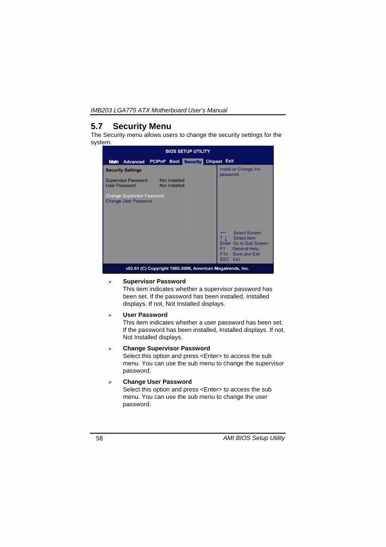
IMB203 LGA775 ATX Motherboard Userrsquos Manual
AMI BIOS Setup Utility 58
57 Security Menu The Security menu allows users to change the security settings for the system
Supervisor Password
This item indicates whether a supervisor password has been set If the password has been installed Installed displays If not Not Installed displays
User Password This item indicates whether a user password has been set If the password has been installed Installed displays If not Not Installed displays
Change Supervisor Password Select this option and press ltEntergt to access the sub menu You can use the sub menu to change the supervisor password
Change User Password Select this option and press ltEntergt to access the sub menu You can use the sub menu to change the user password
IMB203 LGA775 ATX Motherboard Userrsquos Manual
AMI BIOS Setup Utility 59
58 Chipset Menu The Chipset menu allows users to change the advanced chipset settings You can select any of the items in the left frame of the screen to go to the sub menus
North Bridge Configuration South Bridge Configuration ME Subsystem Configuration
For items marked with ldquo rdquo please press ltEntergt for more options
IMB203 LGA775 ATX Motherboard Userrsquos Manual
AMI BIOS Setup Utility 60
North Bridge Configuration
Memory Remap Feature
Use this item to enable or disable the remapping of the overlapped PCI memory above the total physical memory Only 64-bit OS supports this function
DRAM Frequency This item allows you to control the Memory Clock
Configure DRAM Timing by SPD This item can enable or disable DRAM timing by SPD (Serial Presence Detect) device which is a small EEPROM chip on the memory module containing important information about the module speed size addressing mode and various parameters
Memory Hole You can reserve this area of system memory for ISA adapter ROM When this area is reserved it cannot be cached Check the user information of peripherals that need to use this area o f system memory for the memory requirements Here are the options Disabled and 15M-16M
IMB203 LGA775 ATX Motherboard Userrsquos Manual
AMI BIOS Setup Utility 61
Initiate Graphic Adapter When using multiple graphics cards this item can select which graphics controller to be the primary display device during boot
IGD Graphics Mode Select This item allows you to select the amount of system memory used by the internal graphics device
PEG Port ConfigurationPEG Port This item is a toggle to enable or disable the PCI Express port Here are the options for your selection Auto and Disabled
Video Function Configuration Press ltEntergt for the sub-menu for setting up video function
IMB203 LGA775 ATX Motherboard Userrsquos Manual
AMI BIOS Setup Utility 62
South Bridge Configuration
GbE Wake Up From S5 This item specifies whether the system will be awakened from the S5 power
HDA Controller This item allows you to enable or disable the HD audio support
Restore on AC Power Loss This item can control how the PC will behave once power is restored following a power outage or other unexpected shutdown
PCIE Port Configuration This item allows you to set or disable the PCI Express Ports
IMB203 LGA775 ATX Motherboard Userrsquos Manual
AMI BIOS Setup Utility 63
ME Subsystem Configuration
It is strongly recommended that you do not modify these options unless you are an advanced user
IMB203 LGA775 ATX Motherboard Userrsquos Manual
AMI BIOS Setup Utility 64
59 Exit Menu The Exit menu allows users to load your system configuration with optimal or failsafe default values
Save Changes and Exit
When you have completed the system configuration changes select this option to leave Setup and reboot the computer so the new system configuration parameters can take effect Select Save Changes and Exit from the Exit menu and press ltEntergt Select Ok to save changes and exit
Discard Changes and Exit Select this option to quit Setup without making any permanent changes to the system configuration Select Discard Changes and Exit from the Exit menu and press ltEntergt Select Ok to discard changes and exit
Load Optimal Defaults It automatically sets all Setup options to a complete set of default settings when you select this option The Optimal settings are designed for maximum system performance but may not work best for all computer applications In particular do not use the Optimal Setup options if your
IMB203 LGA775 ATX Motherboard Userrsquos Manual
AMI BIOS Setup Utility 65
computer is experiencing system configuration problems Select Load Optimal Defaults from the Exit menu and press ltEntergt
Load Fail-Safe Defaults It automatically sets all Setup options to a complete set of default settings when you select this option The Fail-Safe settings are designed for maximum system stability but not maximum performance Select the Fail-Safe Setup options if your computer is experiencing system configuration problems Select Load Fail-Safe Defaults from the Exit menu and press ltEntergt Select Ok to load Fail-Safe defaults
IMB203 LGA775 ATX Motherboard Userrsquos Manual
AMI BIOS Setup Utility 66
MEMO
IMB203 LGA775 ATX Motherboard Userrsquos Manual
Installation of Drivers 67
CHPATER 6 INSTALLATION OF DRIVERS
The device drivers are located on the Product Information CD-ROM that comes with the IMB203 Series package The auto-run function of drivers will guide you to install the utilities and device drivers under a Windows system You can follow the onscreen instructions to install these devices
Chipse VGA LAN Audio iAMT MEI
61 Installing Chipset Driver 1 Run the SETUPEXE program from the driver directory in
your driver CD Click ldquoNextrdquo to next step
IMB203 LGA775 ATX Motherboard Userrsquos Manual
Installation of Drivers 68
2 An Intelreg License Agreement appears to show you the important information Click ldquoYesrdquo to next step
3 Refer to the Readme file below to view the system requirements and installation information
IMB203 LGA775 ATX Motherboard Userrsquos Manual
Installation of Drivers 69
3-1 Please wait while running the following setup operations
3-2 Please wait while running the following setup operations
IMB203 LGA775 ATX Motherboard Userrsquos Manual
Installation of Drivers 70
4 Click ldquoFinishrdquo to complete the setup process
5 You will be asked to reboot your computer when the installation is completed Please click ldquoYes I want to restart my computer nowrdquo if you donrsquot need to install any other drivers Otherwise please click ldquoNo I will restart my computer laterrdquo and go on next step
IMB203 LGA775 ATX Motherboard Userrsquos Manual
Installation of Drivers 71
62 Installing VGA Driver 1 Run the SETUPEXE program from the driver directory in
your driver CD Click ldquoNextrdquo to next step
2 An Intelreg License Agreement appears to show you the
important information Click ldquoYesrdquo to next step
IMB203 LGA775 ATX Motherboard Userrsquos Manual
Installation of Drivers 72
3 The message of Readme File Information appears to show you the system requirements and installation information Please click ldquoNextrdquo
4 Please wait while running the following setup operations
When this message appears please click ldquoNextrdquo
IMB203 LGA775 ATX Motherboard Userrsquos Manual
Installation of Drivers 73
5 Click ldquoFinishrdquo to complete the setup process
6 You will be asked to reboot your computer when the installation is completed Please click ldquoYes I want to restart my computer nowrdquo if you donrsquot need to install any other drivers Otherwise please click ldquoNo I will restart my computer laterrdquo and click ldquoFinishrdquo to complete the installation
IMB203 LGA775 ATX Motherboard Userrsquos Manual
Installation of Drivers 74
63 Installing LAN Driver
11 Run the InstallShield Wizard for Network Connections from
the driver directory in your driver CD Click ldquoNextrdquo to next step
IMB203 LGA775 ATX Motherboard Userrsquos Manual
Installation of Drivers 75
12 An Intelreg License Agreement appears to show you the important information Click ldquoYesrdquo to next step
13 A Setup Options window appears that you can select the
program features you want to install
IMB203 LGA775 ATX Motherboard Userrsquos Manual
Installation of Drivers 76
2 Click ldquoInstallrdquo to start the installation
3 Please wait while running the following installation operation
IMB203 LGA775 ATX Motherboard Userrsquos Manual
Installation of Drivers 77
4 Click ldquoFinishrdquo to complete the installation
Note The Driver item [Wake on Directed Packet] default is Enabled under Windows Vista
格式化 字型 (符號) Arial
格式化 字型 (符號) Arial
格式化 字型 斜體 字型色彩 黑色 (符號) Arial 非加寬 緊縮
格式化 字型 斜體 字型色彩 黑色 (符號) Arial 非加寬 緊縮
格式化 字型 (符號) Arial 非加寬 緊縮
IMB203 LGA775 ATX Motherboard Userrsquos Manual
Installation of Drivers 78
64 Installing AUDIO Driver 1 Run the InstallShield Wizard for Realtek High Definition
Audio Driver from the driver directory in your driver CD Click ldquoNextrdquo to next step
IMB203 LGA775 ATX Motherboard Userrsquos Manual
Installation of Drivers 79
2 Click ldquoInstallrdquo to start the installation and wait while running the installation operation
3 Click ldquoFinishrdquo to complete the installation
IMB203 LGA775 ATX Motherboard Userrsquos Manual
Installation of Drivers 80
65 Installing iAMT (Active Management Technology) Driver
Note You must download and properly install the required NET version 35 provided from a separate downloading of the actual FimwareTools kit releases posted on VIP prior to loading the MEILMS Driver stack
651 LMS_SOL Setup
1 Run the setup program to install Intelreg Active Management Technology onto your computer It is strongly recommended that you exit all programs before continuing Click ldquoNextrdquo to next step
格式化 字型 (符號) Arial
格式化 字型 (符號) Arial 非加寬 緊縮
IMB203 LGA775 ATX Motherboard Userrsquos Manual
Installation of Drivers 81
2 An Intelreg license agreement appears that you need to continue the setup program by clicking ldquoYesrdquo to accept the terms
IMB203 LGA775 ATX Motherboard Userrsquos Manual
Installation of Drivers 82
3 Refer to the Readme file below to view the system requirements and installation information Click ldquoNextrdquo to next setup
4 Please wait while running the following installation operation
IMB203 LGA775 ATX Motherboard Userrsquos Manual
Installation of Drivers 83
5 Click ldquoFinishrdquo to complete the installation
IMB203 LGA775 ATX Motherboard Userrsquos Manual
Installation of Drivers 84
652 LMS_SOL_IS Setup
1 Run the setup program to install Intelreg Active Management Technology onto your computer It is strongly recommended that you exit all programs before continuing Click ldquoNextrdquo to next step
IMB203 LGA775 ATX Motherboard Userrsquos Manual
Installation of Drivers 85
2 An Intelreg license agreement appears that you need to continue the setup program by clicking ldquoYesrdquo to accept the terms
IMB203 LGA775 ATX Motherboard Userrsquos Manual
Installation of Drivers 86
3 Refer to the Readme file below to view the system requirements and installation information Click ldquoNextrdquo to next setup
4 Please wait while running the following installation operation
IMB203 LGA775 ATX Motherboard Userrsquos Manual
Installation of Drivers 87
5 Click ldquoFinishrdquo to complete the installation
IMB203 LGA775 ATX Motherboard Userrsquos Manual
Installation of Drivers 88
66 Installing MEI (Management Engine Interface) Driver
Note You must download and properly install the required NET version 35 provided from a separate downloading of the actual FimwareTools kit releases posted on VIP prior to loading the MEILMS Driver stack
1 Run the setup program to install Intelreg Management Engine
Interface onto your computer It is strongly recommended that you exit all programs before continuing Click ldquoNextrdquo to next step
格式化 字型 (符號) Arial
格式化 字型 (符號) Arial 非加寬 緊縮
IMB203 LGA775 ATX Motherboard Userrsquos Manual
Installation of Drivers 89
2 An Intelreg license agreement appears that you need to continue the setup program by clicking ldquoYesrdquo to accept the terms
IMB203 LGA775 ATX Motherboard Userrsquos Manual
Installation of Drivers 90
3 Refer to the Readme file below to view the system requirements and installation information Click ldquoNextrdquo to next setup
4 Please wait while running the following installation operation
IMB203 LGA775 ATX Motherboard Userrsquos Manual
Installation of Drivers 91
5 Click ldquoFinishrdquo to complete the installation
IMB203 LGA775 ATX Motherboard Userrsquos Manual
Installation of Drivers 92
MEMO
IMB203 LGA775 ATX Motherboard Userrsquos Manual
Watchdog Timer 93
APPENDIX A WATCHDOG TIMER
Watchdog Timer Setting After the system stops working for a while it can be auto-reset by the Watchdog Timer The integrated Watchdog Timer can be set up in the system reset mode by program
Using the Watchdog Function Start darr Un-Lock WDT O 2E 87 Un-lock super IO
O 2E 87 Un-lock super IO darr Set WDT Function O 2E 2D O 2F 20 Select Logic device O 2E 07 O 2F 08 darr Activate WDT O 2E 30
O 2F 01 Set Second or Minute O 2E F5
O 2F N N=00 or 08(See below table) darr Set base timer O 2E F6
O 2F M=000102hellipFF(Hex) Value=0 to 255 darr WDT counting
re-set timer O 2E F6
O 2F M M=000102hellipFF(See below table) darr
格式化
格式化 項目符號及編號
格式化 項目符號及編號
格式化 字型 8 點 字型色彩黑色
格式化 字型 8 點 字型色彩黑色
格式化 定位點 1257 字元左 + 不在 1012 字元 + 1386字元
格式化 字型 8 點 字型色彩黑色
格式化 定位點 1257 字元左 + 不在 134 字元 + 1362字元
格式化 字型色彩 黑色
格式化 字型色彩 黑色
刪除
IMB203 LGA775 ATX Motherboard Userrsquos Manual
Watchdog Timer 94
IF No re-set timer WDT time-out generate RESET IF to disable WDT O 2E 30
O 2F 00 Can be disable at any time
N=00
M= 00h Time-out Disable 01h Time-out occurs after 1 second 02h Time-out occurs after 2 second 03h Time-out occurs after 3 second helliphelliphelliphelliphelliphelliphelliphelliphellip FFh Time-out occurs after 255 second
N=08
M= 00h Time-out Disable 01h Time-out occurs after 1 minute 02h Time-out occurs after 2 minutes 03h Time-out occurs after 3 minutes helliphelliphelliphelliphelliphelliphelliphelliphellip
FFh Time-out occurs after 255 minutes
格式化 字型色彩 黑色
格式化 字型色彩 黑色
IMB203 LGA775 ATX Motherboard Userrsquos Manual
PCI IRQ Routing 95
APPENDIX B PCI IRQ ROUTING
PICMG PCI IRQ Routing
Device ID Slot Int
PCI Slot 0 31 0 BCDA PCI Slot 1 30 1 CDAB PCI Slot 2 29 2 DABC PCI Slot 3 28 3 ABCD
IMB203 LGA775 ATX Motherboard Userrsquos Manual
PCI IRQ Routing 96
MEMO
IMB203 LGA775 ATX Motherboard Userrsquos Manual
Configuring SATA for RAID Function 97
APPENDIX C CONFIGURING SATA FOR RAID
FUNCTION
Configuring SATA Hard Drive(s) for RAID Function (Controller IntelregICH10DODO DH only) Please follow up the steps below to configure SATA hard drive(s) (1) Install SATA hard drive(s) in your system (2) Enter the BIOS Setup to configure SATA controller mode and boot
sequence (3) Configure RAID by the RAID BIOS (4) Install the SATA controller driver during the OS installation Before you begin the SATA configuration please prepare (a) Two SATA hard drives (to ensure optimal performance it is
recommended that you use two hard drives with identical model and capacity) If you do not want to create RAID with the SATA controller you may prepare only one hard drive
(b) An empty formatted floppy disk (c) Windows XP setup disk (1) Installing SATA hard drive(s) in your system
Connect one end of the SATA signal cable to the rear of the SATA hard drive and the other end to available SATA port(s) on the board Then connect the power connector of power supply to the hard drive
(2) Configuring SATA controller mode and boot sequence by the BIOS Setup You have to make sure whether the SATA controller is configured correctly by system BIOS Setup and set up BIOS boot sequence for the SATA hard drive(s)
IMB203 LGA775 ATX Motherboard Userrsquos Manual
Configuring SATA for RAID Function 98
(2)-1-1 Turn on your system and then press the Del button to enter BIOS Setup during running POST (Power-On Self Test) If you want to create RAID just go to the Advanced Settings menuIDE configuration select the Configure SATA1 as and press ltEntergt for more options
IMB203 LGA775 ATX Motherboard Userrsquos Manual
Configuring SATA for RAID Function 99
(2)-1-2 A list of options appears please select RAID
IMB203 LGA775 ATX Motherboard Userrsquos Manual
Configuring SATA for RAID Function 100
(2)-2 Set CDROM for First Boot Device under the Boot Settings menu to boot CD-ROM after system restarts
(2)-3 Save and exit the BIOS Setup
IMB203 LGA775 ATX Motherboard Userrsquos Manual
Configuring SATA for RAID Function 101
(3) Configuring RAID by the RAID BIOS Enter the RAID BIOS setup utility to configure a RAID array Skip this step and proceed to Section 4 if you do not want to create a RAID (3)-1 After the POST memory testing and before the operating
system booting a message Press ltCtrl-Igt to enter Configuration Utility shows up accordingly press ltCTRL+ Igt to enter the RAID BIOS setup utility
(3)-2 After you press ltCTRL+ Igt the Create RAID Volume screen will appear If you want to create a RAID array select the Create RAID Volume option in the Main Menu and press ENTER
IMB203 LGA775 ATX Motherboard Userrsquos Manual
Configuring SATA for RAID Function 102
(3)-3-1 After entering the CREATE VOLUME MENU screen you can type the disk array name with 1~16 letters (letters cannot be special characters) in the item ldquoNamerdquo
(3)-3-2 When finished press ENTER to select a RAID level There are three RAID levels RAID0 RAID1 and RAID5 amp RAID10 Select a RAID level and press ENTER
IMB203 LGA775 ATX Motherboard Userrsquos Manual
Configuring SATA for RAID Function 103
(3)-4 Set the stripe block size The KB is the standard unit of stripe block size The stripe block size can be 4KB to 128KB After the setting press ENTER for the array capacity
(3)-5 After setting all the items on the menu select Create Volume
and press ENTER to start creating the RAID array
IMB203 LGA775 ATX Motherboard Userrsquos Manual
Configuring SATA for RAID Function 104
(3)-6 When prompting the confirmation press ldquoYldquo to create this volume or ldquoNldquo to cancel the creation
After the creation is completed you can see detailed information about the RAID Array in the DISKVOLUME INFORMATION section including RAID mode disk block size disk name and disk capacity etc
IMB203 LGA775 ATX Motherboard Userrsquos Manual
Configuring SATA for RAID Function 105
Delete RAID Volume If you want to delete a RAID volume select the Delete RAID Volume option in Main Menu Press ENTER and follow on-screen instructions
Please press [ESC] to exit the RAID BIOS utility Now you can proceed to install a SATA driver controller and the operating system
IMB203 LGA775 ATX Motherboard Userrsquos Manual
Configuring SATA for RAID Function 106
(4) Making a SATA Driver Disk To install the operating system onto a serial ATA hard disk successfully you need to install the SATA controller driver during the OS installation Without the driver the hard disk may not be recognized during the Windows setup process First of all please format a blank floppy disk Secondly follow up these steps below to produce a SATA driver disk Users can insert the Driver CD and the formatted blank floppy disk in another system And then please copy all of file of the f6flpy32 folder in the Driver CD to a floppy disk Note Please copy all of file of the f6flpy64 folder if installing 64-bit
Windows Operating System
IMB203 LGA775 ATX Motherboard Userrsquos Manual
Configuring SATA for RAID Function 107
(5) Installing the SATA controller driver during the OS installation Now the SATA driver disk is ready and BIOS settings configured you can proceed to install Windows 2000XP onto your SATA hard drive using the SATA driver Here is an example for Windows XP installation (5)-1 Restart your system to boot the Windows 2000XP Setup disk
and press F6 button as soon as you see the message Press F6 if you need to install a 3rd party SCSI or RAID driver After pressing the F6 button there will be a few moments for some files being loaded before next screen appears
IMB203 LGA775 ATX Motherboard Userrsquos Manual
Configuring SATA for RAID Function 108
(5)-2 When you see the screen below insert the floppy disk containing the SATA driver and press ldquoSrdquo
(5)-3 If the Setup correctly recognizes the driver of the floppy disk
a controller menu will appear below Use the ARROW keys to select Intel(R) ICH8RICH9RICH10RDO SATA RAID Controller and press ENTER Then it will begin to load the SATA driver from the floppy disk
IMB203 LGA775 ATX Motherboard Userrsquos Manual
Configuring SATA for RAID Function 109
Note If a message on the screen saying that one or some file(s) cannot be found please check the floppy disk or copy the correct SATA driver again from the driver CD
IMB203 LGA775 ATX Motherboard Userrsquos Manual
Configuring SATA for RAID Function 110
MEMO
IMB203 LGA775 ATX Motherboard Userrsquos Manual
iAMT Settings 111
APPENDIX D iAMT SETTINGS
The Intelreg Active Management Technology (Intelreg iAMT) has decreased a major barrier to IT efficiency that uses built-in platform capabilities and popular third-party management and security applications to allow IT a better discovering healing and protection their networked computing assets In order to utilize Intel iAMT you must enter the ME BIOS (CTRL + P during system startup) change the ME BIOS password and then select ldquoIntelreg iAMTrdquo as the manageability feature
D1 Entering MEBx 1 You must go to BIOS TO start iAMT function 2 Exit from BIOS after starting iAMT and press Ctrl+P to enter MEBx Setting
It is better to press Ctrl+P before the screen popping out
格式化
IMB203 LGA775 ATX Motherboard Userrsquos Manual
iAMT Settings 112
D2 Set amp Change Password 1 You will be asked to set a password when first log in The default
password is lsquoadminrsquo
2 You will be asked to change the password before setting ME
Change Password
IMB203 LGA775 ATX Motherboard Userrsquos Manual
iAMT Settings 113
3 You must confirm your new password while revising (as Remark 1)
Remark 1 The new password must contain (example 11qqQQ) (default value)
Eight characters
One upper case
One lower case
One number
One special symbol such as $ or
( excepted)
Underline ( _ ) and space are valid characters for password but they wonrsquot make higher complexity
IMB203 LGA775 ATX Motherboard Userrsquos Manual
iAMT Settings 114
D3 Intelreg iAMT Settings 1 Select Intelreg iAMT Configuration and press ltENTERgt
2 Key in the Host Name If Intelreg iAMT set to lsquoDHCPlsquo the Host name must be identical to the operating system mechanic
IMB203 LGA775 ATX Motherboard Userrsquos Manual
iAMT Settings 115
3 Select TCPIP to get into Network interface and set it to lsquoENABLEDrsquo into DHCP Mode and set it to lsquoDISABLEDrsquo (as Remark 2) into Domain name and set the Intel Management Engine domain name such as lsquoAMTintelcomrsquo
(3-1)
(3-2)
IMB203 LGA775 ATX Motherboard Userrsquos Manual
iAMT Settings 116
Remark 2 DHCP Mode lsquoDISABLEDlsquo if DHCP Mode is disabled you can make the following settings
IP address
Subnet mask
IMB203 LGA775 ATX Motherboard Userrsquos Manual
iAMT Settings 117
Default Gateway address
Preferred DNS address
IMB203 LGA775 ATX Motherboard Userrsquos Manual
iAMT Settings 118
Alternate DNS address
Domain name
4 Exit from MEBx after completing the iAMT settings
IMB203 LGA775 ATX Motherboard Userrsquos Manual
iAMT Settings 119
D4 iAMT Web Console 1 From a web browser please type http(IP ADDRESS)16992
which connects to iAMT Web Example http1014021416992
2 To log on you will be required to type in username and password
for access to the Web
USER admin (default value)
PASS (MEBx password)
IMB203 LGA775 ATX Motherboard Userrsquos Manual
iAMT Settings 120
3 Enter the iAMT Web
4 Click Remote Control and select commands on the right side
IMB203 LGA775 ATX Motherboard Userrsquos Manual
iAMT Settings 121
5 When you have finished using the iAMT Web console close the Web browser
IMB203 LGA775 ATX Motherboard Userrsquos Manual
iAMT Settings 122
MEMO
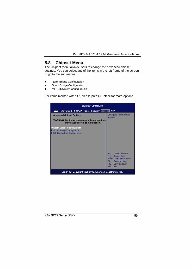
IMB203 LGA775 ATX Motherboard Userrsquos Manual
AMI BIOS Setup Utility 61
Initiate Graphic Adapter When using multiple graphics cards this item can select which graphics controller to be the primary display device during boot
IGD Graphics Mode Select This item allows you to select the amount of system memory used by the internal graphics device
PEG Port ConfigurationPEG Port This item is a toggle to enable or disable the PCI Express port Here are the options for your selection Auto and Disabled
Video Function Configuration Press ltEntergt for the sub-menu for setting up video function
IMB203 LGA775 ATX Motherboard Userrsquos Manual
AMI BIOS Setup Utility 62
South Bridge Configuration
GbE Wake Up From S5 This item specifies whether the system will be awakened from the S5 power
HDA Controller This item allows you to enable or disable the HD audio support
Restore on AC Power Loss This item can control how the PC will behave once power is restored following a power outage or other unexpected shutdown
PCIE Port Configuration This item allows you to set or disable the PCI Express Ports
IMB203 LGA775 ATX Motherboard Userrsquos Manual
AMI BIOS Setup Utility 63
ME Subsystem Configuration
It is strongly recommended that you do not modify these options unless you are an advanced user
IMB203 LGA775 ATX Motherboard Userrsquos Manual
AMI BIOS Setup Utility 64
59 Exit Menu The Exit menu allows users to load your system configuration with optimal or failsafe default values
Save Changes and Exit
When you have completed the system configuration changes select this option to leave Setup and reboot the computer so the new system configuration parameters can take effect Select Save Changes and Exit from the Exit menu and press ltEntergt Select Ok to save changes and exit
Discard Changes and Exit Select this option to quit Setup without making any permanent changes to the system configuration Select Discard Changes and Exit from the Exit menu and press ltEntergt Select Ok to discard changes and exit
Load Optimal Defaults It automatically sets all Setup options to a complete set of default settings when you select this option The Optimal settings are designed for maximum system performance but may not work best for all computer applications In particular do not use the Optimal Setup options if your
IMB203 LGA775 ATX Motherboard Userrsquos Manual
AMI BIOS Setup Utility 65
computer is experiencing system configuration problems Select Load Optimal Defaults from the Exit menu and press ltEntergt
Load Fail-Safe Defaults It automatically sets all Setup options to a complete set of default settings when you select this option The Fail-Safe settings are designed for maximum system stability but not maximum performance Select the Fail-Safe Setup options if your computer is experiencing system configuration problems Select Load Fail-Safe Defaults from the Exit menu and press ltEntergt Select Ok to load Fail-Safe defaults
IMB203 LGA775 ATX Motherboard Userrsquos Manual
AMI BIOS Setup Utility 66
MEMO
IMB203 LGA775 ATX Motherboard Userrsquos Manual
Installation of Drivers 67
CHPATER 6 INSTALLATION OF DRIVERS
The device drivers are located on the Product Information CD-ROM that comes with the IMB203 Series package The auto-run function of drivers will guide you to install the utilities and device drivers under a Windows system You can follow the onscreen instructions to install these devices
Chipse VGA LAN Audio iAMT MEI
61 Installing Chipset Driver 1 Run the SETUPEXE program from the driver directory in
your driver CD Click ldquoNextrdquo to next step
IMB203 LGA775 ATX Motherboard Userrsquos Manual
Installation of Drivers 68
2 An Intelreg License Agreement appears to show you the important information Click ldquoYesrdquo to next step
3 Refer to the Readme file below to view the system requirements and installation information
IMB203 LGA775 ATX Motherboard Userrsquos Manual
Installation of Drivers 69
3-1 Please wait while running the following setup operations
3-2 Please wait while running the following setup operations
IMB203 LGA775 ATX Motherboard Userrsquos Manual
Installation of Drivers 70
4 Click ldquoFinishrdquo to complete the setup process
5 You will be asked to reboot your computer when the installation is completed Please click ldquoYes I want to restart my computer nowrdquo if you donrsquot need to install any other drivers Otherwise please click ldquoNo I will restart my computer laterrdquo and go on next step
IMB203 LGA775 ATX Motherboard Userrsquos Manual
Installation of Drivers 71
62 Installing VGA Driver 1 Run the SETUPEXE program from the driver directory in
your driver CD Click ldquoNextrdquo to next step
2 An Intelreg License Agreement appears to show you the
important information Click ldquoYesrdquo to next step
IMB203 LGA775 ATX Motherboard Userrsquos Manual
Installation of Drivers 72
3 The message of Readme File Information appears to show you the system requirements and installation information Please click ldquoNextrdquo
4 Please wait while running the following setup operations
When this message appears please click ldquoNextrdquo
IMB203 LGA775 ATX Motherboard Userrsquos Manual
Installation of Drivers 73
5 Click ldquoFinishrdquo to complete the setup process
6 You will be asked to reboot your computer when the installation is completed Please click ldquoYes I want to restart my computer nowrdquo if you donrsquot need to install any other drivers Otherwise please click ldquoNo I will restart my computer laterrdquo and click ldquoFinishrdquo to complete the installation
IMB203 LGA775 ATX Motherboard Userrsquos Manual
Installation of Drivers 74
63 Installing LAN Driver
11 Run the InstallShield Wizard for Network Connections from
the driver directory in your driver CD Click ldquoNextrdquo to next step
IMB203 LGA775 ATX Motherboard Userrsquos Manual
Installation of Drivers 75
12 An Intelreg License Agreement appears to show you the important information Click ldquoYesrdquo to next step
13 A Setup Options window appears that you can select the
program features you want to install
IMB203 LGA775 ATX Motherboard Userrsquos Manual
Installation of Drivers 76
2 Click ldquoInstallrdquo to start the installation
3 Please wait while running the following installation operation
IMB203 LGA775 ATX Motherboard Userrsquos Manual
Installation of Drivers 77
4 Click ldquoFinishrdquo to complete the installation
Note The Driver item [Wake on Directed Packet] default is Enabled under Windows Vista
格式化 字型 (符號) Arial
格式化 字型 (符號) Arial
格式化 字型 斜體 字型色彩 黑色 (符號) Arial 非加寬 緊縮
格式化 字型 斜體 字型色彩 黑色 (符號) Arial 非加寬 緊縮
格式化 字型 (符號) Arial 非加寬 緊縮
IMB203 LGA775 ATX Motherboard Userrsquos Manual
Installation of Drivers 78
64 Installing AUDIO Driver 1 Run the InstallShield Wizard for Realtek High Definition
Audio Driver from the driver directory in your driver CD Click ldquoNextrdquo to next step
IMB203 LGA775 ATX Motherboard Userrsquos Manual
Installation of Drivers 79
2 Click ldquoInstallrdquo to start the installation and wait while running the installation operation
3 Click ldquoFinishrdquo to complete the installation
IMB203 LGA775 ATX Motherboard Userrsquos Manual
Installation of Drivers 80
65 Installing iAMT (Active Management Technology) Driver
Note You must download and properly install the required NET version 35 provided from a separate downloading of the actual FimwareTools kit releases posted on VIP prior to loading the MEILMS Driver stack
651 LMS_SOL Setup
1 Run the setup program to install Intelreg Active Management Technology onto your computer It is strongly recommended that you exit all programs before continuing Click ldquoNextrdquo to next step
格式化 字型 (符號) Arial
格式化 字型 (符號) Arial 非加寬 緊縮
IMB203 LGA775 ATX Motherboard Userrsquos Manual
Installation of Drivers 81
2 An Intelreg license agreement appears that you need to continue the setup program by clicking ldquoYesrdquo to accept the terms
IMB203 LGA775 ATX Motherboard Userrsquos Manual
Installation of Drivers 82
3 Refer to the Readme file below to view the system requirements and installation information Click ldquoNextrdquo to next setup
4 Please wait while running the following installation operation
IMB203 LGA775 ATX Motherboard Userrsquos Manual
Installation of Drivers 83
5 Click ldquoFinishrdquo to complete the installation
IMB203 LGA775 ATX Motherboard Userrsquos Manual
Installation of Drivers 84
652 LMS_SOL_IS Setup
1 Run the setup program to install Intelreg Active Management Technology onto your computer It is strongly recommended that you exit all programs before continuing Click ldquoNextrdquo to next step
IMB203 LGA775 ATX Motherboard Userrsquos Manual
Installation of Drivers 85
2 An Intelreg license agreement appears that you need to continue the setup program by clicking ldquoYesrdquo to accept the terms
IMB203 LGA775 ATX Motherboard Userrsquos Manual
Installation of Drivers 86
3 Refer to the Readme file below to view the system requirements and installation information Click ldquoNextrdquo to next setup
4 Please wait while running the following installation operation
IMB203 LGA775 ATX Motherboard Userrsquos Manual
Installation of Drivers 87
5 Click ldquoFinishrdquo to complete the installation
IMB203 LGA775 ATX Motherboard Userrsquos Manual
Installation of Drivers 88
66 Installing MEI (Management Engine Interface) Driver
Note You must download and properly install the required NET version 35 provided from a separate downloading of the actual FimwareTools kit releases posted on VIP prior to loading the MEILMS Driver stack
1 Run the setup program to install Intelreg Management Engine
Interface onto your computer It is strongly recommended that you exit all programs before continuing Click ldquoNextrdquo to next step
格式化 字型 (符號) Arial
格式化 字型 (符號) Arial 非加寬 緊縮
IMB203 LGA775 ATX Motherboard Userrsquos Manual
Installation of Drivers 89
2 An Intelreg license agreement appears that you need to continue the setup program by clicking ldquoYesrdquo to accept the terms
IMB203 LGA775 ATX Motherboard Userrsquos Manual
Installation of Drivers 90
3 Refer to the Readme file below to view the system requirements and installation information Click ldquoNextrdquo to next setup
4 Please wait while running the following installation operation
IMB203 LGA775 ATX Motherboard Userrsquos Manual
Installation of Drivers 91
5 Click ldquoFinishrdquo to complete the installation
IMB203 LGA775 ATX Motherboard Userrsquos Manual
Installation of Drivers 92
MEMO
IMB203 LGA775 ATX Motherboard Userrsquos Manual
Watchdog Timer 93
APPENDIX A WATCHDOG TIMER
Watchdog Timer Setting After the system stops working for a while it can be auto-reset by the Watchdog Timer The integrated Watchdog Timer can be set up in the system reset mode by program
Using the Watchdog Function Start darr Un-Lock WDT O 2E 87 Un-lock super IO
O 2E 87 Un-lock super IO darr Set WDT Function O 2E 2D O 2F 20 Select Logic device O 2E 07 O 2F 08 darr Activate WDT O 2E 30
O 2F 01 Set Second or Minute O 2E F5
O 2F N N=00 or 08(See below table) darr Set base timer O 2E F6
O 2F M=000102hellipFF(Hex) Value=0 to 255 darr WDT counting
re-set timer O 2E F6
O 2F M M=000102hellipFF(See below table) darr
格式化
格式化 項目符號及編號
格式化 項目符號及編號
格式化 字型 8 點 字型色彩黑色
格式化 字型 8 點 字型色彩黑色
格式化 定位點 1257 字元左 + 不在 1012 字元 + 1386字元
格式化 字型 8 點 字型色彩黑色
格式化 定位點 1257 字元左 + 不在 134 字元 + 1362字元
格式化 字型色彩 黑色
格式化 字型色彩 黑色
刪除
IMB203 LGA775 ATX Motherboard Userrsquos Manual
Watchdog Timer 94
IF No re-set timer WDT time-out generate RESET IF to disable WDT O 2E 30
O 2F 00 Can be disable at any time
N=00
M= 00h Time-out Disable 01h Time-out occurs after 1 second 02h Time-out occurs after 2 second 03h Time-out occurs after 3 second helliphelliphelliphelliphelliphelliphelliphelliphellip FFh Time-out occurs after 255 second
N=08
M= 00h Time-out Disable 01h Time-out occurs after 1 minute 02h Time-out occurs after 2 minutes 03h Time-out occurs after 3 minutes helliphelliphelliphelliphelliphelliphelliphelliphellip
FFh Time-out occurs after 255 minutes
格式化 字型色彩 黑色
格式化 字型色彩 黑色
IMB203 LGA775 ATX Motherboard Userrsquos Manual
PCI IRQ Routing 95
APPENDIX B PCI IRQ ROUTING
PICMG PCI IRQ Routing
Device ID Slot Int
PCI Slot 0 31 0 BCDA PCI Slot 1 30 1 CDAB PCI Slot 2 29 2 DABC PCI Slot 3 28 3 ABCD
IMB203 LGA775 ATX Motherboard Userrsquos Manual
PCI IRQ Routing 96
MEMO
IMB203 LGA775 ATX Motherboard Userrsquos Manual
Configuring SATA for RAID Function 97
APPENDIX C CONFIGURING SATA FOR RAID
FUNCTION
Configuring SATA Hard Drive(s) for RAID Function (Controller IntelregICH10DODO DH only) Please follow up the steps below to configure SATA hard drive(s) (1) Install SATA hard drive(s) in your system (2) Enter the BIOS Setup to configure SATA controller mode and boot
sequence (3) Configure RAID by the RAID BIOS (4) Install the SATA controller driver during the OS installation Before you begin the SATA configuration please prepare (a) Two SATA hard drives (to ensure optimal performance it is
recommended that you use two hard drives with identical model and capacity) If you do not want to create RAID with the SATA controller you may prepare only one hard drive
(b) An empty formatted floppy disk (c) Windows XP setup disk (1) Installing SATA hard drive(s) in your system
Connect one end of the SATA signal cable to the rear of the SATA hard drive and the other end to available SATA port(s) on the board Then connect the power connector of power supply to the hard drive
(2) Configuring SATA controller mode and boot sequence by the BIOS Setup You have to make sure whether the SATA controller is configured correctly by system BIOS Setup and set up BIOS boot sequence for the SATA hard drive(s)
IMB203 LGA775 ATX Motherboard Userrsquos Manual
Configuring SATA for RAID Function 98
(2)-1-1 Turn on your system and then press the Del button to enter BIOS Setup during running POST (Power-On Self Test) If you want to create RAID just go to the Advanced Settings menuIDE configuration select the Configure SATA1 as and press ltEntergt for more options
IMB203 LGA775 ATX Motherboard Userrsquos Manual
Configuring SATA for RAID Function 99
(2)-1-2 A list of options appears please select RAID
IMB203 LGA775 ATX Motherboard Userrsquos Manual
Configuring SATA for RAID Function 100
(2)-2 Set CDROM for First Boot Device under the Boot Settings menu to boot CD-ROM after system restarts
(2)-3 Save and exit the BIOS Setup
IMB203 LGA775 ATX Motherboard Userrsquos Manual
Configuring SATA for RAID Function 101
(3) Configuring RAID by the RAID BIOS Enter the RAID BIOS setup utility to configure a RAID array Skip this step and proceed to Section 4 if you do not want to create a RAID (3)-1 After the POST memory testing and before the operating
system booting a message Press ltCtrl-Igt to enter Configuration Utility shows up accordingly press ltCTRL+ Igt to enter the RAID BIOS setup utility
(3)-2 After you press ltCTRL+ Igt the Create RAID Volume screen will appear If you want to create a RAID array select the Create RAID Volume option in the Main Menu and press ENTER
IMB203 LGA775 ATX Motherboard Userrsquos Manual
Configuring SATA for RAID Function 102
(3)-3-1 After entering the CREATE VOLUME MENU screen you can type the disk array name with 1~16 letters (letters cannot be special characters) in the item ldquoNamerdquo
(3)-3-2 When finished press ENTER to select a RAID level There are three RAID levels RAID0 RAID1 and RAID5 amp RAID10 Select a RAID level and press ENTER
IMB203 LGA775 ATX Motherboard Userrsquos Manual
Configuring SATA for RAID Function 103
(3)-4 Set the stripe block size The KB is the standard unit of stripe block size The stripe block size can be 4KB to 128KB After the setting press ENTER for the array capacity
(3)-5 After setting all the items on the menu select Create Volume
and press ENTER to start creating the RAID array
IMB203 LGA775 ATX Motherboard Userrsquos Manual
Configuring SATA for RAID Function 104
(3)-6 When prompting the confirmation press ldquoYldquo to create this volume or ldquoNldquo to cancel the creation
After the creation is completed you can see detailed information about the RAID Array in the DISKVOLUME INFORMATION section including RAID mode disk block size disk name and disk capacity etc
IMB203 LGA775 ATX Motherboard Userrsquos Manual
Configuring SATA for RAID Function 105
Delete RAID Volume If you want to delete a RAID volume select the Delete RAID Volume option in Main Menu Press ENTER and follow on-screen instructions
Please press [ESC] to exit the RAID BIOS utility Now you can proceed to install a SATA driver controller and the operating system
IMB203 LGA775 ATX Motherboard Userrsquos Manual
Configuring SATA for RAID Function 106
(4) Making a SATA Driver Disk To install the operating system onto a serial ATA hard disk successfully you need to install the SATA controller driver during the OS installation Without the driver the hard disk may not be recognized during the Windows setup process First of all please format a blank floppy disk Secondly follow up these steps below to produce a SATA driver disk Users can insert the Driver CD and the formatted blank floppy disk in another system And then please copy all of file of the f6flpy32 folder in the Driver CD to a floppy disk Note Please copy all of file of the f6flpy64 folder if installing 64-bit
Windows Operating System
IMB203 LGA775 ATX Motherboard Userrsquos Manual
Configuring SATA for RAID Function 107
(5) Installing the SATA controller driver during the OS installation Now the SATA driver disk is ready and BIOS settings configured you can proceed to install Windows 2000XP onto your SATA hard drive using the SATA driver Here is an example for Windows XP installation (5)-1 Restart your system to boot the Windows 2000XP Setup disk
and press F6 button as soon as you see the message Press F6 if you need to install a 3rd party SCSI or RAID driver After pressing the F6 button there will be a few moments for some files being loaded before next screen appears
IMB203 LGA775 ATX Motherboard Userrsquos Manual
Configuring SATA for RAID Function 108
(5)-2 When you see the screen below insert the floppy disk containing the SATA driver and press ldquoSrdquo
(5)-3 If the Setup correctly recognizes the driver of the floppy disk
a controller menu will appear below Use the ARROW keys to select Intel(R) ICH8RICH9RICH10RDO SATA RAID Controller and press ENTER Then it will begin to load the SATA driver from the floppy disk
IMB203 LGA775 ATX Motherboard Userrsquos Manual
Configuring SATA for RAID Function 109
Note If a message on the screen saying that one or some file(s) cannot be found please check the floppy disk or copy the correct SATA driver again from the driver CD
IMB203 LGA775 ATX Motherboard Userrsquos Manual
Configuring SATA for RAID Function 110
MEMO
IMB203 LGA775 ATX Motherboard Userrsquos Manual
iAMT Settings 111
APPENDIX D iAMT SETTINGS
The Intelreg Active Management Technology (Intelreg iAMT) has decreased a major barrier to IT efficiency that uses built-in platform capabilities and popular third-party management and security applications to allow IT a better discovering healing and protection their networked computing assets In order to utilize Intel iAMT you must enter the ME BIOS (CTRL + P during system startup) change the ME BIOS password and then select ldquoIntelreg iAMTrdquo as the manageability feature
D1 Entering MEBx 1 You must go to BIOS TO start iAMT function 2 Exit from BIOS after starting iAMT and press Ctrl+P to enter MEBx Setting
It is better to press Ctrl+P before the screen popping out
格式化
IMB203 LGA775 ATX Motherboard Userrsquos Manual
iAMT Settings 112
D2 Set amp Change Password 1 You will be asked to set a password when first log in The default
password is lsquoadminrsquo
2 You will be asked to change the password before setting ME
Change Password
IMB203 LGA775 ATX Motherboard Userrsquos Manual
iAMT Settings 113
3 You must confirm your new password while revising (as Remark 1)
Remark 1 The new password must contain (example 11qqQQ) (default value)
Eight characters
One upper case
One lower case
One number
One special symbol such as $ or
( excepted)
Underline ( _ ) and space are valid characters for password but they wonrsquot make higher complexity
IMB203 LGA775 ATX Motherboard Userrsquos Manual
iAMT Settings 114
D3 Intelreg iAMT Settings 1 Select Intelreg iAMT Configuration and press ltENTERgt
2 Key in the Host Name If Intelreg iAMT set to lsquoDHCPlsquo the Host name must be identical to the operating system mechanic
IMB203 LGA775 ATX Motherboard Userrsquos Manual
iAMT Settings 115
3 Select TCPIP to get into Network interface and set it to lsquoENABLEDrsquo into DHCP Mode and set it to lsquoDISABLEDrsquo (as Remark 2) into Domain name and set the Intel Management Engine domain name such as lsquoAMTintelcomrsquo
(3-1)
(3-2)
IMB203 LGA775 ATX Motherboard Userrsquos Manual
iAMT Settings 116
Remark 2 DHCP Mode lsquoDISABLEDlsquo if DHCP Mode is disabled you can make the following settings
IP address
Subnet mask
IMB203 LGA775 ATX Motherboard Userrsquos Manual
iAMT Settings 117
Default Gateway address
Preferred DNS address
IMB203 LGA775 ATX Motherboard Userrsquos Manual
iAMT Settings 118
Alternate DNS address
Domain name
4 Exit from MEBx after completing the iAMT settings
IMB203 LGA775 ATX Motherboard Userrsquos Manual
iAMT Settings 119
D4 iAMT Web Console 1 From a web browser please type http(IP ADDRESS)16992
which connects to iAMT Web Example http1014021416992
2 To log on you will be required to type in username and password
for access to the Web
USER admin (default value)
PASS (MEBx password)
IMB203 LGA775 ATX Motherboard Userrsquos Manual
iAMT Settings 120
3 Enter the iAMT Web
4 Click Remote Control and select commands on the right side
IMB203 LGA775 ATX Motherboard Userrsquos Manual
iAMT Settings 121
5 When you have finished using the iAMT Web console close the Web browser
IMB203 LGA775 ATX Motherboard Userrsquos Manual
iAMT Settings 122
MEMO
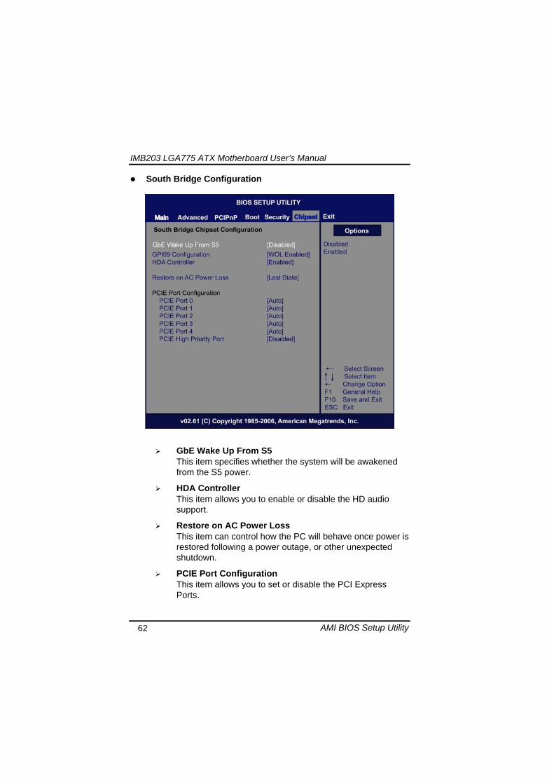
IMB203 LGA775 ATX Motherboard Userrsquos Manual
Installation of Drivers 67
CHPATER 6 INSTALLATION OF DRIVERS
The device drivers are located on the Product Information CD-ROM that comes with the IMB203 Series package The auto-run function of drivers will guide you to install the utilities and device drivers under a Windows system You can follow the onscreen instructions to install these devices
Chipse VGA LAN Audio iAMT MEI
61 Installing Chipset Driver 1 Run the SETUPEXE program from the driver directory in
your driver CD Click ldquoNextrdquo to next step
IMB203 LGA775 ATX Motherboard Userrsquos Manual
Installation of Drivers 68
2 An Intelreg License Agreement appears to show you the important information Click ldquoYesrdquo to next step
3 Refer to the Readme file below to view the system requirements and installation information
IMB203 LGA775 ATX Motherboard Userrsquos Manual
Installation of Drivers 69
3-1 Please wait while running the following setup operations
3-2 Please wait while running the following setup operations
IMB203 LGA775 ATX Motherboard Userrsquos Manual
Installation of Drivers 70
4 Click ldquoFinishrdquo to complete the setup process
5 You will be asked to reboot your computer when the installation is completed Please click ldquoYes I want to restart my computer nowrdquo if you donrsquot need to install any other drivers Otherwise please click ldquoNo I will restart my computer laterrdquo and go on next step
IMB203 LGA775 ATX Motherboard Userrsquos Manual
Installation of Drivers 71
62 Installing VGA Driver 1 Run the SETUPEXE program from the driver directory in
your driver CD Click ldquoNextrdquo to next step
2 An Intelreg License Agreement appears to show you the
important information Click ldquoYesrdquo to next step
IMB203 LGA775 ATX Motherboard Userrsquos Manual
Installation of Drivers 72
3 The message of Readme File Information appears to show you the system requirements and installation information Please click ldquoNextrdquo
4 Please wait while running the following setup operations
When this message appears please click ldquoNextrdquo
IMB203 LGA775 ATX Motherboard Userrsquos Manual
Installation of Drivers 73
5 Click ldquoFinishrdquo to complete the setup process
6 You will be asked to reboot your computer when the installation is completed Please click ldquoYes I want to restart my computer nowrdquo if you donrsquot need to install any other drivers Otherwise please click ldquoNo I will restart my computer laterrdquo and click ldquoFinishrdquo to complete the installation
IMB203 LGA775 ATX Motherboard Userrsquos Manual
Installation of Drivers 74
63 Installing LAN Driver
11 Run the InstallShield Wizard for Network Connections from
the driver directory in your driver CD Click ldquoNextrdquo to next step
IMB203 LGA775 ATX Motherboard Userrsquos Manual
Installation of Drivers 75
12 An Intelreg License Agreement appears to show you the important information Click ldquoYesrdquo to next step
13 A Setup Options window appears that you can select the
program features you want to install
IMB203 LGA775 ATX Motherboard Userrsquos Manual
Installation of Drivers 76
2 Click ldquoInstallrdquo to start the installation
3 Please wait while running the following installation operation
IMB203 LGA775 ATX Motherboard Userrsquos Manual
Installation of Drivers 77
4 Click ldquoFinishrdquo to complete the installation
Note The Driver item [Wake on Directed Packet] default is Enabled under Windows Vista
格式化 字型 (符號) Arial
格式化 字型 (符號) Arial
格式化 字型 斜體 字型色彩 黑色 (符號) Arial 非加寬 緊縮
格式化 字型 斜體 字型色彩 黑色 (符號) Arial 非加寬 緊縮
格式化 字型 (符號) Arial 非加寬 緊縮
IMB203 LGA775 ATX Motherboard Userrsquos Manual
Installation of Drivers 78
64 Installing AUDIO Driver 1 Run the InstallShield Wizard for Realtek High Definition
Audio Driver from the driver directory in your driver CD Click ldquoNextrdquo to next step
IMB203 LGA775 ATX Motherboard Userrsquos Manual
Installation of Drivers 79
2 Click ldquoInstallrdquo to start the installation and wait while running the installation operation
3 Click ldquoFinishrdquo to complete the installation
IMB203 LGA775 ATX Motherboard Userrsquos Manual
Installation of Drivers 80
65 Installing iAMT (Active Management Technology) Driver
Note You must download and properly install the required NET version 35 provided from a separate downloading of the actual FimwareTools kit releases posted on VIP prior to loading the MEILMS Driver stack
651 LMS_SOL Setup
1 Run the setup program to install Intelreg Active Management Technology onto your computer It is strongly recommended that you exit all programs before continuing Click ldquoNextrdquo to next step
格式化 字型 (符號) Arial
格式化 字型 (符號) Arial 非加寬 緊縮
IMB203 LGA775 ATX Motherboard Userrsquos Manual
Installation of Drivers 81
2 An Intelreg license agreement appears that you need to continue the setup program by clicking ldquoYesrdquo to accept the terms
IMB203 LGA775 ATX Motherboard Userrsquos Manual
Installation of Drivers 82
3 Refer to the Readme file below to view the system requirements and installation information Click ldquoNextrdquo to next setup
4 Please wait while running the following installation operation
IMB203 LGA775 ATX Motherboard Userrsquos Manual
Installation of Drivers 83
5 Click ldquoFinishrdquo to complete the installation
IMB203 LGA775 ATX Motherboard Userrsquos Manual
Installation of Drivers 84
652 LMS_SOL_IS Setup
1 Run the setup program to install Intelreg Active Management Technology onto your computer It is strongly recommended that you exit all programs before continuing Click ldquoNextrdquo to next step
IMB203 LGA775 ATX Motherboard Userrsquos Manual
Installation of Drivers 85
2 An Intelreg license agreement appears that you need to continue the setup program by clicking ldquoYesrdquo to accept the terms
IMB203 LGA775 ATX Motherboard Userrsquos Manual
Installation of Drivers 86
3 Refer to the Readme file below to view the system requirements and installation information Click ldquoNextrdquo to next setup
4 Please wait while running the following installation operation
IMB203 LGA775 ATX Motherboard Userrsquos Manual
Installation of Drivers 87
5 Click ldquoFinishrdquo to complete the installation
IMB203 LGA775 ATX Motherboard Userrsquos Manual
Installation of Drivers 88
66 Installing MEI (Management Engine Interface) Driver
Note You must download and properly install the required NET version 35 provided from a separate downloading of the actual FimwareTools kit releases posted on VIP prior to loading the MEILMS Driver stack
1 Run the setup program to install Intelreg Management Engine
Interface onto your computer It is strongly recommended that you exit all programs before continuing Click ldquoNextrdquo to next step
格式化 字型 (符號) Arial
格式化 字型 (符號) Arial 非加寬 緊縮
IMB203 LGA775 ATX Motherboard Userrsquos Manual
Installation of Drivers 89
2 An Intelreg license agreement appears that you need to continue the setup program by clicking ldquoYesrdquo to accept the terms
IMB203 LGA775 ATX Motherboard Userrsquos Manual
Installation of Drivers 90
3 Refer to the Readme file below to view the system requirements and installation information Click ldquoNextrdquo to next setup
4 Please wait while running the following installation operation
IMB203 LGA775 ATX Motherboard Userrsquos Manual
Installation of Drivers 91
5 Click ldquoFinishrdquo to complete the installation
IMB203 LGA775 ATX Motherboard Userrsquos Manual
Installation of Drivers 92
MEMO
IMB203 LGA775 ATX Motherboard Userrsquos Manual
Watchdog Timer 93
APPENDIX A WATCHDOG TIMER
Watchdog Timer Setting After the system stops working for a while it can be auto-reset by the Watchdog Timer The integrated Watchdog Timer can be set up in the system reset mode by program
Using the Watchdog Function Start darr Un-Lock WDT O 2E 87 Un-lock super IO
O 2E 87 Un-lock super IO darr Set WDT Function O 2E 2D O 2F 20 Select Logic device O 2E 07 O 2F 08 darr Activate WDT O 2E 30
O 2F 01 Set Second or Minute O 2E F5
O 2F N N=00 or 08(See below table) darr Set base timer O 2E F6
O 2F M=000102hellipFF(Hex) Value=0 to 255 darr WDT counting
re-set timer O 2E F6
O 2F M M=000102hellipFF(See below table) darr
格式化
格式化 項目符號及編號
格式化 項目符號及編號
格式化 字型 8 點 字型色彩黑色
格式化 字型 8 點 字型色彩黑色
格式化 定位點 1257 字元左 + 不在 1012 字元 + 1386字元
格式化 字型 8 點 字型色彩黑色
格式化 定位點 1257 字元左 + 不在 134 字元 + 1362字元
格式化 字型色彩 黑色
格式化 字型色彩 黑色
刪除
IMB203 LGA775 ATX Motherboard Userrsquos Manual
Watchdog Timer 94
IF No re-set timer WDT time-out generate RESET IF to disable WDT O 2E 30
O 2F 00 Can be disable at any time
N=00
M= 00h Time-out Disable 01h Time-out occurs after 1 second 02h Time-out occurs after 2 second 03h Time-out occurs after 3 second helliphelliphelliphelliphelliphelliphelliphelliphellip FFh Time-out occurs after 255 second
N=08
M= 00h Time-out Disable 01h Time-out occurs after 1 minute 02h Time-out occurs after 2 minutes 03h Time-out occurs after 3 minutes helliphelliphelliphelliphelliphelliphelliphelliphellip
FFh Time-out occurs after 255 minutes
格式化 字型色彩 黑色
格式化 字型色彩 黑色
IMB203 LGA775 ATX Motherboard Userrsquos Manual
PCI IRQ Routing 95
APPENDIX B PCI IRQ ROUTING
PICMG PCI IRQ Routing
Device ID Slot Int
PCI Slot 0 31 0 BCDA PCI Slot 1 30 1 CDAB PCI Slot 2 29 2 DABC PCI Slot 3 28 3 ABCD
IMB203 LGA775 ATX Motherboard Userrsquos Manual
PCI IRQ Routing 96
MEMO
IMB203 LGA775 ATX Motherboard Userrsquos Manual
Configuring SATA for RAID Function 97
APPENDIX C CONFIGURING SATA FOR RAID
FUNCTION
Configuring SATA Hard Drive(s) for RAID Function (Controller IntelregICH10DODO DH only) Please follow up the steps below to configure SATA hard drive(s) (1) Install SATA hard drive(s) in your system (2) Enter the BIOS Setup to configure SATA controller mode and boot
sequence (3) Configure RAID by the RAID BIOS (4) Install the SATA controller driver during the OS installation Before you begin the SATA configuration please prepare (a) Two SATA hard drives (to ensure optimal performance it is
recommended that you use two hard drives with identical model and capacity) If you do not want to create RAID with the SATA controller you may prepare only one hard drive
(b) An empty formatted floppy disk (c) Windows XP setup disk (1) Installing SATA hard drive(s) in your system
Connect one end of the SATA signal cable to the rear of the SATA hard drive and the other end to available SATA port(s) on the board Then connect the power connector of power supply to the hard drive
(2) Configuring SATA controller mode and boot sequence by the BIOS Setup You have to make sure whether the SATA controller is configured correctly by system BIOS Setup and set up BIOS boot sequence for the SATA hard drive(s)
IMB203 LGA775 ATX Motherboard Userrsquos Manual
Configuring SATA for RAID Function 98
(2)-1-1 Turn on your system and then press the Del button to enter BIOS Setup during running POST (Power-On Self Test) If you want to create RAID just go to the Advanced Settings menuIDE configuration select the Configure SATA1 as and press ltEntergt for more options
IMB203 LGA775 ATX Motherboard Userrsquos Manual
Configuring SATA for RAID Function 99
(2)-1-2 A list of options appears please select RAID
IMB203 LGA775 ATX Motherboard Userrsquos Manual
Configuring SATA for RAID Function 100
(2)-2 Set CDROM for First Boot Device under the Boot Settings menu to boot CD-ROM after system restarts
(2)-3 Save and exit the BIOS Setup
IMB203 LGA775 ATX Motherboard Userrsquos Manual
Configuring SATA for RAID Function 101
(3) Configuring RAID by the RAID BIOS Enter the RAID BIOS setup utility to configure a RAID array Skip this step and proceed to Section 4 if you do not want to create a RAID (3)-1 After the POST memory testing and before the operating
system booting a message Press ltCtrl-Igt to enter Configuration Utility shows up accordingly press ltCTRL+ Igt to enter the RAID BIOS setup utility
(3)-2 After you press ltCTRL+ Igt the Create RAID Volume screen will appear If you want to create a RAID array select the Create RAID Volume option in the Main Menu and press ENTER
IMB203 LGA775 ATX Motherboard Userrsquos Manual
Configuring SATA for RAID Function 102
(3)-3-1 After entering the CREATE VOLUME MENU screen you can type the disk array name with 1~16 letters (letters cannot be special characters) in the item ldquoNamerdquo
(3)-3-2 When finished press ENTER to select a RAID level There are three RAID levels RAID0 RAID1 and RAID5 amp RAID10 Select a RAID level and press ENTER
IMB203 LGA775 ATX Motherboard Userrsquos Manual
Configuring SATA for RAID Function 103
(3)-4 Set the stripe block size The KB is the standard unit of stripe block size The stripe block size can be 4KB to 128KB After the setting press ENTER for the array capacity
(3)-5 After setting all the items on the menu select Create Volume
and press ENTER to start creating the RAID array
IMB203 LGA775 ATX Motherboard Userrsquos Manual
Configuring SATA for RAID Function 104
(3)-6 When prompting the confirmation press ldquoYldquo to create this volume or ldquoNldquo to cancel the creation
After the creation is completed you can see detailed information about the RAID Array in the DISKVOLUME INFORMATION section including RAID mode disk block size disk name and disk capacity etc
IMB203 LGA775 ATX Motherboard Userrsquos Manual
Configuring SATA for RAID Function 105
Delete RAID Volume If you want to delete a RAID volume select the Delete RAID Volume option in Main Menu Press ENTER and follow on-screen instructions
Please press [ESC] to exit the RAID BIOS utility Now you can proceed to install a SATA driver controller and the operating system
IMB203 LGA775 ATX Motherboard Userrsquos Manual
Configuring SATA for RAID Function 106
(4) Making a SATA Driver Disk To install the operating system onto a serial ATA hard disk successfully you need to install the SATA controller driver during the OS installation Without the driver the hard disk may not be recognized during the Windows setup process First of all please format a blank floppy disk Secondly follow up these steps below to produce a SATA driver disk Users can insert the Driver CD and the formatted blank floppy disk in another system And then please copy all of file of the f6flpy32 folder in the Driver CD to a floppy disk Note Please copy all of file of the f6flpy64 folder if installing 64-bit
Windows Operating System
IMB203 LGA775 ATX Motherboard Userrsquos Manual
Configuring SATA for RAID Function 107
(5) Installing the SATA controller driver during the OS installation Now the SATA driver disk is ready and BIOS settings configured you can proceed to install Windows 2000XP onto your SATA hard drive using the SATA driver Here is an example for Windows XP installation (5)-1 Restart your system to boot the Windows 2000XP Setup disk
and press F6 button as soon as you see the message Press F6 if you need to install a 3rd party SCSI or RAID driver After pressing the F6 button there will be a few moments for some files being loaded before next screen appears
IMB203 LGA775 ATX Motherboard Userrsquos Manual
Configuring SATA for RAID Function 108
(5)-2 When you see the screen below insert the floppy disk containing the SATA driver and press ldquoSrdquo
(5)-3 If the Setup correctly recognizes the driver of the floppy disk
a controller menu will appear below Use the ARROW keys to select Intel(R) ICH8RICH9RICH10RDO SATA RAID Controller and press ENTER Then it will begin to load the SATA driver from the floppy disk
IMB203 LGA775 ATX Motherboard Userrsquos Manual
Configuring SATA for RAID Function 109
Note If a message on the screen saying that one or some file(s) cannot be found please check the floppy disk or copy the correct SATA driver again from the driver CD
IMB203 LGA775 ATX Motherboard Userrsquos Manual
Configuring SATA for RAID Function 110
MEMO
IMB203 LGA775 ATX Motherboard Userrsquos Manual
iAMT Settings 111
APPENDIX D iAMT SETTINGS
The Intelreg Active Management Technology (Intelreg iAMT) has decreased a major barrier to IT efficiency that uses built-in platform capabilities and popular third-party management and security applications to allow IT a better discovering healing and protection their networked computing assets In order to utilize Intel iAMT you must enter the ME BIOS (CTRL + P during system startup) change the ME BIOS password and then select ldquoIntelreg iAMTrdquo as the manageability feature
D1 Entering MEBx 1 You must go to BIOS TO start iAMT function 2 Exit from BIOS after starting iAMT and press Ctrl+P to enter MEBx Setting
It is better to press Ctrl+P before the screen popping out
格式化
IMB203 LGA775 ATX Motherboard Userrsquos Manual
iAMT Settings 112
D2 Set amp Change Password 1 You will be asked to set a password when first log in The default
password is lsquoadminrsquo
2 You will be asked to change the password before setting ME
Change Password
IMB203 LGA775 ATX Motherboard Userrsquos Manual
iAMT Settings 113
3 You must confirm your new password while revising (as Remark 1)
Remark 1 The new password must contain (example 11qqQQ) (default value)
Eight characters
One upper case
One lower case
One number
One special symbol such as $ or
( excepted)
Underline ( _ ) and space are valid characters for password but they wonrsquot make higher complexity
IMB203 LGA775 ATX Motherboard Userrsquos Manual
iAMT Settings 114
D3 Intelreg iAMT Settings 1 Select Intelreg iAMT Configuration and press ltENTERgt
2 Key in the Host Name If Intelreg iAMT set to lsquoDHCPlsquo the Host name must be identical to the operating system mechanic
IMB203 LGA775 ATX Motherboard Userrsquos Manual
iAMT Settings 115
3 Select TCPIP to get into Network interface and set it to lsquoENABLEDrsquo into DHCP Mode and set it to lsquoDISABLEDrsquo (as Remark 2) into Domain name and set the Intel Management Engine domain name such as lsquoAMTintelcomrsquo
(3-1)
(3-2)
IMB203 LGA775 ATX Motherboard Userrsquos Manual
iAMT Settings 116
Remark 2 DHCP Mode lsquoDISABLEDlsquo if DHCP Mode is disabled you can make the following settings
IP address
Subnet mask
IMB203 LGA775 ATX Motherboard Userrsquos Manual
iAMT Settings 117
Default Gateway address
Preferred DNS address
IMB203 LGA775 ATX Motherboard Userrsquos Manual
iAMT Settings 118
Alternate DNS address
Domain name
4 Exit from MEBx after completing the iAMT settings
IMB203 LGA775 ATX Motherboard Userrsquos Manual
iAMT Settings 119
D4 iAMT Web Console 1 From a web browser please type http(IP ADDRESS)16992
which connects to iAMT Web Example http1014021416992
2 To log on you will be required to type in username and password
for access to the Web
USER admin (default value)
PASS (MEBx password)
IMB203 LGA775 ATX Motherboard Userrsquos Manual
iAMT Settings 120
3 Enter the iAMT Web
4 Click Remote Control and select commands on the right side
IMB203 LGA775 ATX Motherboard Userrsquos Manual
iAMT Settings 121
5 When you have finished using the iAMT Web console close the Web browser
IMB203 LGA775 ATX Motherboard Userrsquos Manual
iAMT Settings 122
MEMO
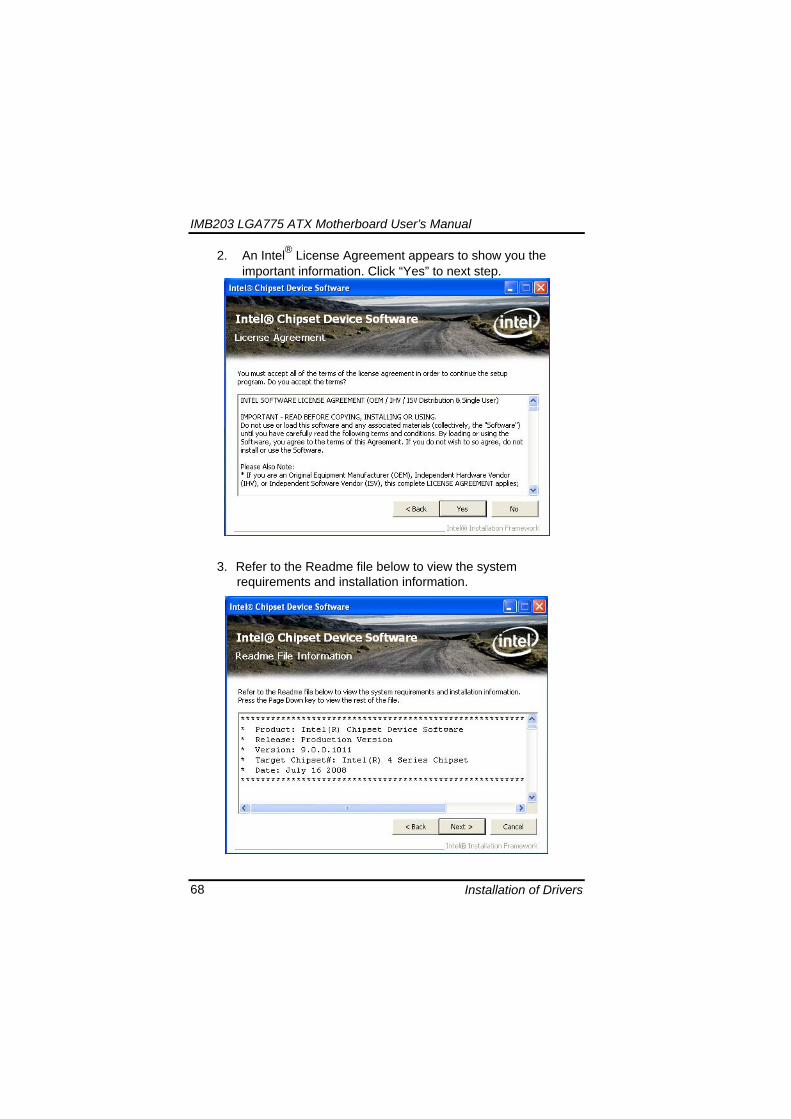
IMB203 LGA775 ATX Motherboard Userrsquos Manual
Installation of Drivers 68
2 An Intelreg License Agreement appears to show you the important information Click ldquoYesrdquo to next step
3 Refer to the Readme file below to view the system requirements and installation information
IMB203 LGA775 ATX Motherboard Userrsquos Manual
Installation of Drivers 69
3-1 Please wait while running the following setup operations
3-2 Please wait while running the following setup operations
IMB203 LGA775 ATX Motherboard Userrsquos Manual
Installation of Drivers 70
4 Click ldquoFinishrdquo to complete the setup process
5 You will be asked to reboot your computer when the installation is completed Please click ldquoYes I want to restart my computer nowrdquo if you donrsquot need to install any other drivers Otherwise please click ldquoNo I will restart my computer laterrdquo and go on next step
IMB203 LGA775 ATX Motherboard Userrsquos Manual
Installation of Drivers 71
62 Installing VGA Driver 1 Run the SETUPEXE program from the driver directory in
your driver CD Click ldquoNextrdquo to next step
2 An Intelreg License Agreement appears to show you the
important information Click ldquoYesrdquo to next step
IMB203 LGA775 ATX Motherboard Userrsquos Manual
Installation of Drivers 72
3 The message of Readme File Information appears to show you the system requirements and installation information Please click ldquoNextrdquo
4 Please wait while running the following setup operations
When this message appears please click ldquoNextrdquo
IMB203 LGA775 ATX Motherboard Userrsquos Manual
Installation of Drivers 73
5 Click ldquoFinishrdquo to complete the setup process
6 You will be asked to reboot your computer when the installation is completed Please click ldquoYes I want to restart my computer nowrdquo if you donrsquot need to install any other drivers Otherwise please click ldquoNo I will restart my computer laterrdquo and click ldquoFinishrdquo to complete the installation
IMB203 LGA775 ATX Motherboard Userrsquos Manual
Installation of Drivers 74
63 Installing LAN Driver
11 Run the InstallShield Wizard for Network Connections from
the driver directory in your driver CD Click ldquoNextrdquo to next step
IMB203 LGA775 ATX Motherboard Userrsquos Manual
Installation of Drivers 75
12 An Intelreg License Agreement appears to show you the important information Click ldquoYesrdquo to next step
13 A Setup Options window appears that you can select the
program features you want to install
IMB203 LGA775 ATX Motherboard Userrsquos Manual
Installation of Drivers 76
2 Click ldquoInstallrdquo to start the installation
3 Please wait while running the following installation operation
IMB203 LGA775 ATX Motherboard Userrsquos Manual
Installation of Drivers 77
4 Click ldquoFinishrdquo to complete the installation
Note The Driver item [Wake on Directed Packet] default is Enabled under Windows Vista
格式化 字型 (符號) Arial
格式化 字型 (符號) Arial
格式化 字型 斜體 字型色彩 黑色 (符號) Arial 非加寬 緊縮
格式化 字型 斜體 字型色彩 黑色 (符號) Arial 非加寬 緊縮
格式化 字型 (符號) Arial 非加寬 緊縮
IMB203 LGA775 ATX Motherboard Userrsquos Manual
Installation of Drivers 78
64 Installing AUDIO Driver 1 Run the InstallShield Wizard for Realtek High Definition
Audio Driver from the driver directory in your driver CD Click ldquoNextrdquo to next step
IMB203 LGA775 ATX Motherboard Userrsquos Manual
Installation of Drivers 79
2 Click ldquoInstallrdquo to start the installation and wait while running the installation operation
3 Click ldquoFinishrdquo to complete the installation
IMB203 LGA775 ATX Motherboard Userrsquos Manual
Installation of Drivers 80
65 Installing iAMT (Active Management Technology) Driver
Note You must download and properly install the required NET version 35 provided from a separate downloading of the actual FimwareTools kit releases posted on VIP prior to loading the MEILMS Driver stack
651 LMS_SOL Setup
1 Run the setup program to install Intelreg Active Management Technology onto your computer It is strongly recommended that you exit all programs before continuing Click ldquoNextrdquo to next step
格式化 字型 (符號) Arial
格式化 字型 (符號) Arial 非加寬 緊縮
IMB203 LGA775 ATX Motherboard Userrsquos Manual
Installation of Drivers 81
2 An Intelreg license agreement appears that you need to continue the setup program by clicking ldquoYesrdquo to accept the terms
IMB203 LGA775 ATX Motherboard Userrsquos Manual
Installation of Drivers 82
3 Refer to the Readme file below to view the system requirements and installation information Click ldquoNextrdquo to next setup
4 Please wait while running the following installation operation
IMB203 LGA775 ATX Motherboard Userrsquos Manual
Installation of Drivers 83
5 Click ldquoFinishrdquo to complete the installation
IMB203 LGA775 ATX Motherboard Userrsquos Manual
Installation of Drivers 84
652 LMS_SOL_IS Setup
1 Run the setup program to install Intelreg Active Management Technology onto your computer It is strongly recommended that you exit all programs before continuing Click ldquoNextrdquo to next step
IMB203 LGA775 ATX Motherboard Userrsquos Manual
Installation of Drivers 85
2 An Intelreg license agreement appears that you need to continue the setup program by clicking ldquoYesrdquo to accept the terms
IMB203 LGA775 ATX Motherboard Userrsquos Manual
Installation of Drivers 86
3 Refer to the Readme file below to view the system requirements and installation information Click ldquoNextrdquo to next setup
4 Please wait while running the following installation operation
IMB203 LGA775 ATX Motherboard Userrsquos Manual
Installation of Drivers 87
5 Click ldquoFinishrdquo to complete the installation
IMB203 LGA775 ATX Motherboard Userrsquos Manual
Installation of Drivers 88
66 Installing MEI (Management Engine Interface) Driver
Note You must download and properly install the required NET version 35 provided from a separate downloading of the actual FimwareTools kit releases posted on VIP prior to loading the MEILMS Driver stack
1 Run the setup program to install Intelreg Management Engine
Interface onto your computer It is strongly recommended that you exit all programs before continuing Click ldquoNextrdquo to next step
格式化 字型 (符號) Arial
格式化 字型 (符號) Arial 非加寬 緊縮
IMB203 LGA775 ATX Motherboard Userrsquos Manual
Installation of Drivers 89
2 An Intelreg license agreement appears that you need to continue the setup program by clicking ldquoYesrdquo to accept the terms
IMB203 LGA775 ATX Motherboard Userrsquos Manual
Installation of Drivers 90
3 Refer to the Readme file below to view the system requirements and installation information Click ldquoNextrdquo to next setup
4 Please wait while running the following installation operation
IMB203 LGA775 ATX Motherboard Userrsquos Manual
Installation of Drivers 91
5 Click ldquoFinishrdquo to complete the installation
IMB203 LGA775 ATX Motherboard Userrsquos Manual
Installation of Drivers 92
MEMO
IMB203 LGA775 ATX Motherboard Userrsquos Manual
Watchdog Timer 93
APPENDIX A WATCHDOG TIMER
Watchdog Timer Setting After the system stops working for a while it can be auto-reset by the Watchdog Timer The integrated Watchdog Timer can be set up in the system reset mode by program
Using the Watchdog Function Start darr Un-Lock WDT O 2E 87 Un-lock super IO
O 2E 87 Un-lock super IO darr Set WDT Function O 2E 2D O 2F 20 Select Logic device O 2E 07 O 2F 08 darr Activate WDT O 2E 30
O 2F 01 Set Second or Minute O 2E F5
O 2F N N=00 or 08(See below table) darr Set base timer O 2E F6
O 2F M=000102hellipFF(Hex) Value=0 to 255 darr WDT counting
re-set timer O 2E F6
O 2F M M=000102hellipFF(See below table) darr
格式化
格式化 項目符號及編號
格式化 項目符號及編號
格式化 字型 8 點 字型色彩黑色
格式化 字型 8 點 字型色彩黑色
格式化 定位點 1257 字元左 + 不在 1012 字元 + 1386字元
格式化 字型 8 點 字型色彩黑色
格式化 定位點 1257 字元左 + 不在 134 字元 + 1362字元
格式化 字型色彩 黑色
格式化 字型色彩 黑色
刪除
IMB203 LGA775 ATX Motherboard Userrsquos Manual
Watchdog Timer 94
IF No re-set timer WDT time-out generate RESET IF to disable WDT O 2E 30
O 2F 00 Can be disable at any time
N=00
M= 00h Time-out Disable 01h Time-out occurs after 1 second 02h Time-out occurs after 2 second 03h Time-out occurs after 3 second helliphelliphelliphelliphelliphelliphelliphelliphellip FFh Time-out occurs after 255 second
N=08
M= 00h Time-out Disable 01h Time-out occurs after 1 minute 02h Time-out occurs after 2 minutes 03h Time-out occurs after 3 minutes helliphelliphelliphelliphelliphelliphelliphelliphellip
FFh Time-out occurs after 255 minutes
格式化 字型色彩 黑色
格式化 字型色彩 黑色
IMB203 LGA775 ATX Motherboard Userrsquos Manual
PCI IRQ Routing 95
APPENDIX B PCI IRQ ROUTING
PICMG PCI IRQ Routing
Device ID Slot Int
PCI Slot 0 31 0 BCDA PCI Slot 1 30 1 CDAB PCI Slot 2 29 2 DABC PCI Slot 3 28 3 ABCD
IMB203 LGA775 ATX Motherboard Userrsquos Manual
PCI IRQ Routing 96
MEMO
IMB203 LGA775 ATX Motherboard Userrsquos Manual
Configuring SATA for RAID Function 97
APPENDIX C CONFIGURING SATA FOR RAID
FUNCTION
Configuring SATA Hard Drive(s) for RAID Function (Controller IntelregICH10DODO DH only) Please follow up the steps below to configure SATA hard drive(s) (1) Install SATA hard drive(s) in your system (2) Enter the BIOS Setup to configure SATA controller mode and boot
sequence (3) Configure RAID by the RAID BIOS (4) Install the SATA controller driver during the OS installation Before you begin the SATA configuration please prepare (a) Two SATA hard drives (to ensure optimal performance it is
recommended that you use two hard drives with identical model and capacity) If you do not want to create RAID with the SATA controller you may prepare only one hard drive
(b) An empty formatted floppy disk (c) Windows XP setup disk (1) Installing SATA hard drive(s) in your system
Connect one end of the SATA signal cable to the rear of the SATA hard drive and the other end to available SATA port(s) on the board Then connect the power connector of power supply to the hard drive
(2) Configuring SATA controller mode and boot sequence by the BIOS Setup You have to make sure whether the SATA controller is configured correctly by system BIOS Setup and set up BIOS boot sequence for the SATA hard drive(s)
IMB203 LGA775 ATX Motherboard Userrsquos Manual
Configuring SATA for RAID Function 98
(2)-1-1 Turn on your system and then press the Del button to enter BIOS Setup during running POST (Power-On Self Test) If you want to create RAID just go to the Advanced Settings menuIDE configuration select the Configure SATA1 as and press ltEntergt for more options
IMB203 LGA775 ATX Motherboard Userrsquos Manual
Configuring SATA for RAID Function 99
(2)-1-2 A list of options appears please select RAID
IMB203 LGA775 ATX Motherboard Userrsquos Manual
Configuring SATA for RAID Function 100
(2)-2 Set CDROM for First Boot Device under the Boot Settings menu to boot CD-ROM after system restarts
(2)-3 Save and exit the BIOS Setup
IMB203 LGA775 ATX Motherboard Userrsquos Manual
Configuring SATA for RAID Function 101
(3) Configuring RAID by the RAID BIOS Enter the RAID BIOS setup utility to configure a RAID array Skip this step and proceed to Section 4 if you do not want to create a RAID (3)-1 After the POST memory testing and before the operating
system booting a message Press ltCtrl-Igt to enter Configuration Utility shows up accordingly press ltCTRL+ Igt to enter the RAID BIOS setup utility
(3)-2 After you press ltCTRL+ Igt the Create RAID Volume screen will appear If you want to create a RAID array select the Create RAID Volume option in the Main Menu and press ENTER
IMB203 LGA775 ATX Motherboard Userrsquos Manual
Configuring SATA for RAID Function 102
(3)-3-1 After entering the CREATE VOLUME MENU screen you can type the disk array name with 1~16 letters (letters cannot be special characters) in the item ldquoNamerdquo
(3)-3-2 When finished press ENTER to select a RAID level There are three RAID levels RAID0 RAID1 and RAID5 amp RAID10 Select a RAID level and press ENTER
IMB203 LGA775 ATX Motherboard Userrsquos Manual
Configuring SATA for RAID Function 103
(3)-4 Set the stripe block size The KB is the standard unit of stripe block size The stripe block size can be 4KB to 128KB After the setting press ENTER for the array capacity
(3)-5 After setting all the items on the menu select Create Volume
and press ENTER to start creating the RAID array
IMB203 LGA775 ATX Motherboard Userrsquos Manual
Configuring SATA for RAID Function 104
(3)-6 When prompting the confirmation press ldquoYldquo to create this volume or ldquoNldquo to cancel the creation
After the creation is completed you can see detailed information about the RAID Array in the DISKVOLUME INFORMATION section including RAID mode disk block size disk name and disk capacity etc
IMB203 LGA775 ATX Motherboard Userrsquos Manual
Configuring SATA for RAID Function 105
Delete RAID Volume If you want to delete a RAID volume select the Delete RAID Volume option in Main Menu Press ENTER and follow on-screen instructions
Please press [ESC] to exit the RAID BIOS utility Now you can proceed to install a SATA driver controller and the operating system
IMB203 LGA775 ATX Motherboard Userrsquos Manual
Configuring SATA for RAID Function 106
(4) Making a SATA Driver Disk To install the operating system onto a serial ATA hard disk successfully you need to install the SATA controller driver during the OS installation Without the driver the hard disk may not be recognized during the Windows setup process First of all please format a blank floppy disk Secondly follow up these steps below to produce a SATA driver disk Users can insert the Driver CD and the formatted blank floppy disk in another system And then please copy all of file of the f6flpy32 folder in the Driver CD to a floppy disk Note Please copy all of file of the f6flpy64 folder if installing 64-bit
Windows Operating System
IMB203 LGA775 ATX Motherboard Userrsquos Manual
Configuring SATA for RAID Function 107
(5) Installing the SATA controller driver during the OS installation Now the SATA driver disk is ready and BIOS settings configured you can proceed to install Windows 2000XP onto your SATA hard drive using the SATA driver Here is an example for Windows XP installation (5)-1 Restart your system to boot the Windows 2000XP Setup disk
and press F6 button as soon as you see the message Press F6 if you need to install a 3rd party SCSI or RAID driver After pressing the F6 button there will be a few moments for some files being loaded before next screen appears
IMB203 LGA775 ATX Motherboard Userrsquos Manual
Configuring SATA for RAID Function 108
(5)-2 When you see the screen below insert the floppy disk containing the SATA driver and press ldquoSrdquo
(5)-3 If the Setup correctly recognizes the driver of the floppy disk
a controller menu will appear below Use the ARROW keys to select Intel(R) ICH8RICH9RICH10RDO SATA RAID Controller and press ENTER Then it will begin to load the SATA driver from the floppy disk
IMB203 LGA775 ATX Motherboard Userrsquos Manual
Configuring SATA for RAID Function 109
Note If a message on the screen saying that one or some file(s) cannot be found please check the floppy disk or copy the correct SATA driver again from the driver CD
IMB203 LGA775 ATX Motherboard Userrsquos Manual
Configuring SATA for RAID Function 110
MEMO
IMB203 LGA775 ATX Motherboard Userrsquos Manual
iAMT Settings 111
APPENDIX D iAMT SETTINGS
The Intelreg Active Management Technology (Intelreg iAMT) has decreased a major barrier to IT efficiency that uses built-in platform capabilities and popular third-party management and security applications to allow IT a better discovering healing and protection their networked computing assets In order to utilize Intel iAMT you must enter the ME BIOS (CTRL + P during system startup) change the ME BIOS password and then select ldquoIntelreg iAMTrdquo as the manageability feature
D1 Entering MEBx 1 You must go to BIOS TO start iAMT function 2 Exit from BIOS after starting iAMT and press Ctrl+P to enter MEBx Setting
It is better to press Ctrl+P before the screen popping out
格式化
IMB203 LGA775 ATX Motherboard Userrsquos Manual
iAMT Settings 112
D2 Set amp Change Password 1 You will be asked to set a password when first log in The default
password is lsquoadminrsquo
2 You will be asked to change the password before setting ME
Change Password
IMB203 LGA775 ATX Motherboard Userrsquos Manual
iAMT Settings 113
3 You must confirm your new password while revising (as Remark 1)
Remark 1 The new password must contain (example 11qqQQ) (default value)
Eight characters
One upper case
One lower case
One number
One special symbol such as $ or
( excepted)
Underline ( _ ) and space are valid characters for password but they wonrsquot make higher complexity
IMB203 LGA775 ATX Motherboard Userrsquos Manual
iAMT Settings 114
D3 Intelreg iAMT Settings 1 Select Intelreg iAMT Configuration and press ltENTERgt
2 Key in the Host Name If Intelreg iAMT set to lsquoDHCPlsquo the Host name must be identical to the operating system mechanic
IMB203 LGA775 ATX Motherboard Userrsquos Manual
iAMT Settings 115
3 Select TCPIP to get into Network interface and set it to lsquoENABLEDrsquo into DHCP Mode and set it to lsquoDISABLEDrsquo (as Remark 2) into Domain name and set the Intel Management Engine domain name such as lsquoAMTintelcomrsquo
(3-1)
(3-2)
IMB203 LGA775 ATX Motherboard Userrsquos Manual
iAMT Settings 116
Remark 2 DHCP Mode lsquoDISABLEDlsquo if DHCP Mode is disabled you can make the following settings
IP address
Subnet mask
IMB203 LGA775 ATX Motherboard Userrsquos Manual
iAMT Settings 117
Default Gateway address
Preferred DNS address
IMB203 LGA775 ATX Motherboard Userrsquos Manual
iAMT Settings 118
Alternate DNS address
Domain name
4 Exit from MEBx after completing the iAMT settings
IMB203 LGA775 ATX Motherboard Userrsquos Manual
iAMT Settings 119
D4 iAMT Web Console 1 From a web browser please type http(IP ADDRESS)16992
which connects to iAMT Web Example http1014021416992
2 To log on you will be required to type in username and password
for access to the Web
USER admin (default value)
PASS (MEBx password)
IMB203 LGA775 ATX Motherboard Userrsquos Manual
iAMT Settings 120
3 Enter the iAMT Web
4 Click Remote Control and select commands on the right side
IMB203 LGA775 ATX Motherboard Userrsquos Manual
iAMT Settings 121
5 When you have finished using the iAMT Web console close the Web browser
IMB203 LGA775 ATX Motherboard Userrsquos Manual
iAMT Settings 122
MEMO
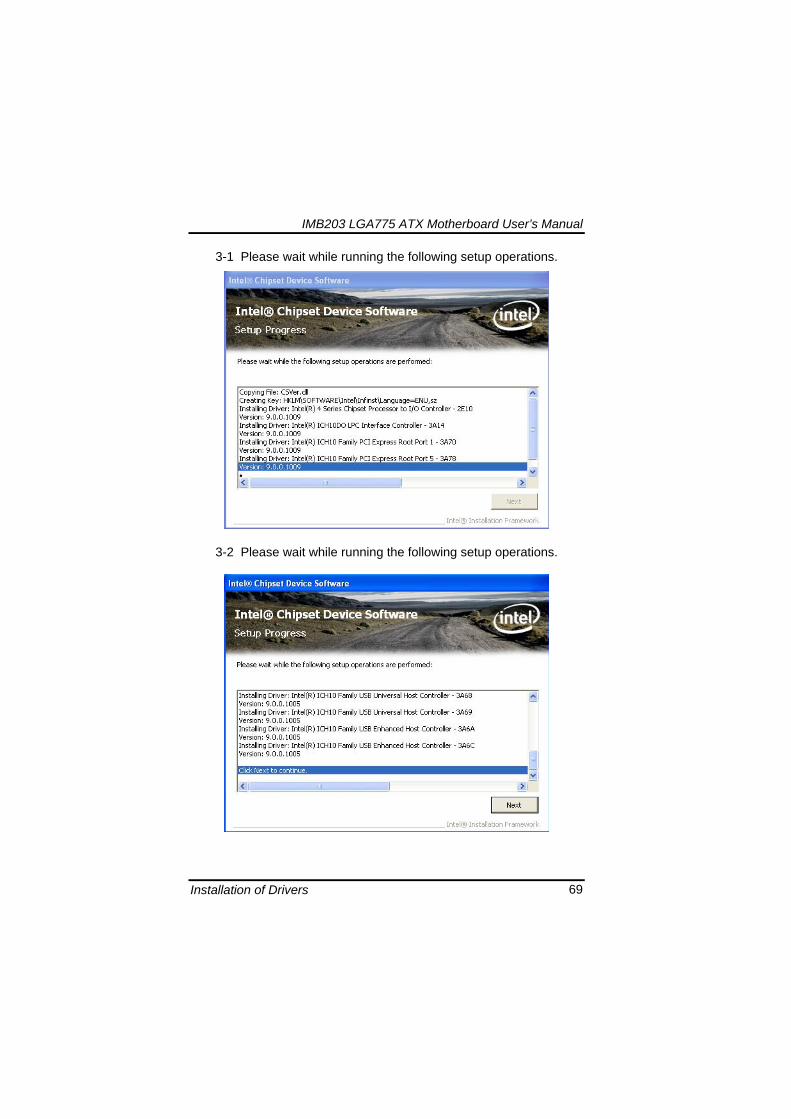
IMB203 LGA775 ATX Motherboard Userrsquos Manual
Installation of Drivers 69
3-1 Please wait while running the following setup operations
3-2 Please wait while running the following setup operations
IMB203 LGA775 ATX Motherboard Userrsquos Manual
Installation of Drivers 70
4 Click ldquoFinishrdquo to complete the setup process
5 You will be asked to reboot your computer when the installation is completed Please click ldquoYes I want to restart my computer nowrdquo if you donrsquot need to install any other drivers Otherwise please click ldquoNo I will restart my computer laterrdquo and go on next step
IMB203 LGA775 ATX Motherboard Userrsquos Manual
Installation of Drivers 71
62 Installing VGA Driver 1 Run the SETUPEXE program from the driver directory in
your driver CD Click ldquoNextrdquo to next step
2 An Intelreg License Agreement appears to show you the
important information Click ldquoYesrdquo to next step
IMB203 LGA775 ATX Motherboard Userrsquos Manual
Installation of Drivers 72
3 The message of Readme File Information appears to show you the system requirements and installation information Please click ldquoNextrdquo
4 Please wait while running the following setup operations
When this message appears please click ldquoNextrdquo
IMB203 LGA775 ATX Motherboard Userrsquos Manual
Installation of Drivers 73
5 Click ldquoFinishrdquo to complete the setup process
6 You will be asked to reboot your computer when the installation is completed Please click ldquoYes I want to restart my computer nowrdquo if you donrsquot need to install any other drivers Otherwise please click ldquoNo I will restart my computer laterrdquo and click ldquoFinishrdquo to complete the installation
IMB203 LGA775 ATX Motherboard Userrsquos Manual
Installation of Drivers 74
63 Installing LAN Driver
11 Run the InstallShield Wizard for Network Connections from
the driver directory in your driver CD Click ldquoNextrdquo to next step
IMB203 LGA775 ATX Motherboard Userrsquos Manual
Installation of Drivers 75
12 An Intelreg License Agreement appears to show you the important information Click ldquoYesrdquo to next step
13 A Setup Options window appears that you can select the
program features you want to install
IMB203 LGA775 ATX Motherboard Userrsquos Manual
Installation of Drivers 76
2 Click ldquoInstallrdquo to start the installation
3 Please wait while running the following installation operation
IMB203 LGA775 ATX Motherboard Userrsquos Manual
Installation of Drivers 77
4 Click ldquoFinishrdquo to complete the installation
Note The Driver item [Wake on Directed Packet] default is Enabled under Windows Vista
格式化 字型 (符號) Arial
格式化 字型 (符號) Arial
格式化 字型 斜體 字型色彩 黑色 (符號) Arial 非加寬 緊縮
格式化 字型 斜體 字型色彩 黑色 (符號) Arial 非加寬 緊縮
格式化 字型 (符號) Arial 非加寬 緊縮
IMB203 LGA775 ATX Motherboard Userrsquos Manual
Installation of Drivers 78
64 Installing AUDIO Driver 1 Run the InstallShield Wizard for Realtek High Definition
Audio Driver from the driver directory in your driver CD Click ldquoNextrdquo to next step
IMB203 LGA775 ATX Motherboard Userrsquos Manual
Installation of Drivers 79
2 Click ldquoInstallrdquo to start the installation and wait while running the installation operation
3 Click ldquoFinishrdquo to complete the installation
IMB203 LGA775 ATX Motherboard Userrsquos Manual
Installation of Drivers 80
65 Installing iAMT (Active Management Technology) Driver
Note You must download and properly install the required NET version 35 provided from a separate downloading of the actual FimwareTools kit releases posted on VIP prior to loading the MEILMS Driver stack
651 LMS_SOL Setup
1 Run the setup program to install Intelreg Active Management Technology onto your computer It is strongly recommended that you exit all programs before continuing Click ldquoNextrdquo to next step
格式化 字型 (符號) Arial
格式化 字型 (符號) Arial 非加寬 緊縮
IMB203 LGA775 ATX Motherboard Userrsquos Manual
Installation of Drivers 81
2 An Intelreg license agreement appears that you need to continue the setup program by clicking ldquoYesrdquo to accept the terms
IMB203 LGA775 ATX Motherboard Userrsquos Manual
Installation of Drivers 82
3 Refer to the Readme file below to view the system requirements and installation information Click ldquoNextrdquo to next setup
4 Please wait while running the following installation operation
IMB203 LGA775 ATX Motherboard Userrsquos Manual
Installation of Drivers 83
5 Click ldquoFinishrdquo to complete the installation
IMB203 LGA775 ATX Motherboard Userrsquos Manual
Installation of Drivers 84
652 LMS_SOL_IS Setup
1 Run the setup program to install Intelreg Active Management Technology onto your computer It is strongly recommended that you exit all programs before continuing Click ldquoNextrdquo to next step
IMB203 LGA775 ATX Motherboard Userrsquos Manual
Installation of Drivers 85
2 An Intelreg license agreement appears that you need to continue the setup program by clicking ldquoYesrdquo to accept the terms
IMB203 LGA775 ATX Motherboard Userrsquos Manual
Installation of Drivers 86
3 Refer to the Readme file below to view the system requirements and installation information Click ldquoNextrdquo to next setup
4 Please wait while running the following installation operation
IMB203 LGA775 ATX Motherboard Userrsquos Manual
Installation of Drivers 87
5 Click ldquoFinishrdquo to complete the installation
IMB203 LGA775 ATX Motherboard Userrsquos Manual
Installation of Drivers 88
66 Installing MEI (Management Engine Interface) Driver
Note You must download and properly install the required NET version 35 provided from a separate downloading of the actual FimwareTools kit releases posted on VIP prior to loading the MEILMS Driver stack
1 Run the setup program to install Intelreg Management Engine
Interface onto your computer It is strongly recommended that you exit all programs before continuing Click ldquoNextrdquo to next step
格式化 字型 (符號) Arial
格式化 字型 (符號) Arial 非加寬 緊縮
IMB203 LGA775 ATX Motherboard Userrsquos Manual
Installation of Drivers 89
2 An Intelreg license agreement appears that you need to continue the setup program by clicking ldquoYesrdquo to accept the terms
IMB203 LGA775 ATX Motherboard Userrsquos Manual
Installation of Drivers 90
3 Refer to the Readme file below to view the system requirements and installation information Click ldquoNextrdquo to next setup
4 Please wait while running the following installation operation
IMB203 LGA775 ATX Motherboard Userrsquos Manual
Installation of Drivers 91
5 Click ldquoFinishrdquo to complete the installation
IMB203 LGA775 ATX Motherboard Userrsquos Manual
Installation of Drivers 92
MEMO
IMB203 LGA775 ATX Motherboard Userrsquos Manual
Watchdog Timer 93
APPENDIX A WATCHDOG TIMER
Watchdog Timer Setting After the system stops working for a while it can be auto-reset by the Watchdog Timer The integrated Watchdog Timer can be set up in the system reset mode by program
Using the Watchdog Function Start darr Un-Lock WDT O 2E 87 Un-lock super IO
O 2E 87 Un-lock super IO darr Set WDT Function O 2E 2D O 2F 20 Select Logic device O 2E 07 O 2F 08 darr Activate WDT O 2E 30
O 2F 01 Set Second or Minute O 2E F5
O 2F N N=00 or 08(See below table) darr Set base timer O 2E F6
O 2F M=000102hellipFF(Hex) Value=0 to 255 darr WDT counting
re-set timer O 2E F6
O 2F M M=000102hellipFF(See below table) darr
格式化
格式化 項目符號及編號
格式化 項目符號及編號
格式化 字型 8 點 字型色彩黑色
格式化 字型 8 點 字型色彩黑色
格式化 定位點 1257 字元左 + 不在 1012 字元 + 1386字元
格式化 字型 8 點 字型色彩黑色
格式化 定位點 1257 字元左 + 不在 134 字元 + 1362字元
格式化 字型色彩 黑色
格式化 字型色彩 黑色
刪除
IMB203 LGA775 ATX Motherboard Userrsquos Manual
Watchdog Timer 94
IF No re-set timer WDT time-out generate RESET IF to disable WDT O 2E 30
O 2F 00 Can be disable at any time
N=00
M= 00h Time-out Disable 01h Time-out occurs after 1 second 02h Time-out occurs after 2 second 03h Time-out occurs after 3 second helliphelliphelliphelliphelliphelliphelliphelliphellip FFh Time-out occurs after 255 second
N=08
M= 00h Time-out Disable 01h Time-out occurs after 1 minute 02h Time-out occurs after 2 minutes 03h Time-out occurs after 3 minutes helliphelliphelliphelliphelliphelliphelliphelliphellip
FFh Time-out occurs after 255 minutes
格式化 字型色彩 黑色
格式化 字型色彩 黑色
IMB203 LGA775 ATX Motherboard Userrsquos Manual
PCI IRQ Routing 95
APPENDIX B PCI IRQ ROUTING
PICMG PCI IRQ Routing
Device ID Slot Int
PCI Slot 0 31 0 BCDA PCI Slot 1 30 1 CDAB PCI Slot 2 29 2 DABC PCI Slot 3 28 3 ABCD
IMB203 LGA775 ATX Motherboard Userrsquos Manual
PCI IRQ Routing 96
MEMO
IMB203 LGA775 ATX Motherboard Userrsquos Manual
Configuring SATA for RAID Function 97
APPENDIX C CONFIGURING SATA FOR RAID
FUNCTION
Configuring SATA Hard Drive(s) for RAID Function (Controller IntelregICH10DODO DH only) Please follow up the steps below to configure SATA hard drive(s) (1) Install SATA hard drive(s) in your system (2) Enter the BIOS Setup to configure SATA controller mode and boot
sequence (3) Configure RAID by the RAID BIOS (4) Install the SATA controller driver during the OS installation Before you begin the SATA configuration please prepare (a) Two SATA hard drives (to ensure optimal performance it is
recommended that you use two hard drives with identical model and capacity) If you do not want to create RAID with the SATA controller you may prepare only one hard drive
(b) An empty formatted floppy disk (c) Windows XP setup disk (1) Installing SATA hard drive(s) in your system
Connect one end of the SATA signal cable to the rear of the SATA hard drive and the other end to available SATA port(s) on the board Then connect the power connector of power supply to the hard drive
(2) Configuring SATA controller mode and boot sequence by the BIOS Setup You have to make sure whether the SATA controller is configured correctly by system BIOS Setup and set up BIOS boot sequence for the SATA hard drive(s)
IMB203 LGA775 ATX Motherboard Userrsquos Manual
Configuring SATA for RAID Function 98
(2)-1-1 Turn on your system and then press the Del button to enter BIOS Setup during running POST (Power-On Self Test) If you want to create RAID just go to the Advanced Settings menuIDE configuration select the Configure SATA1 as and press ltEntergt for more options
IMB203 LGA775 ATX Motherboard Userrsquos Manual
Configuring SATA for RAID Function 99
(2)-1-2 A list of options appears please select RAID
IMB203 LGA775 ATX Motherboard Userrsquos Manual
Configuring SATA for RAID Function 100
(2)-2 Set CDROM for First Boot Device under the Boot Settings menu to boot CD-ROM after system restarts
(2)-3 Save and exit the BIOS Setup
IMB203 LGA775 ATX Motherboard Userrsquos Manual
Configuring SATA for RAID Function 101
(3) Configuring RAID by the RAID BIOS Enter the RAID BIOS setup utility to configure a RAID array Skip this step and proceed to Section 4 if you do not want to create a RAID (3)-1 After the POST memory testing and before the operating
system booting a message Press ltCtrl-Igt to enter Configuration Utility shows up accordingly press ltCTRL+ Igt to enter the RAID BIOS setup utility
(3)-2 After you press ltCTRL+ Igt the Create RAID Volume screen will appear If you want to create a RAID array select the Create RAID Volume option in the Main Menu and press ENTER
IMB203 LGA775 ATX Motherboard Userrsquos Manual
Configuring SATA for RAID Function 102
(3)-3-1 After entering the CREATE VOLUME MENU screen you can type the disk array name with 1~16 letters (letters cannot be special characters) in the item ldquoNamerdquo
(3)-3-2 When finished press ENTER to select a RAID level There are three RAID levels RAID0 RAID1 and RAID5 amp RAID10 Select a RAID level and press ENTER
IMB203 LGA775 ATX Motherboard Userrsquos Manual
Configuring SATA for RAID Function 103
(3)-4 Set the stripe block size The KB is the standard unit of stripe block size The stripe block size can be 4KB to 128KB After the setting press ENTER for the array capacity
(3)-5 After setting all the items on the menu select Create Volume
and press ENTER to start creating the RAID array
IMB203 LGA775 ATX Motherboard Userrsquos Manual
Configuring SATA for RAID Function 104
(3)-6 When prompting the confirmation press ldquoYldquo to create this volume or ldquoNldquo to cancel the creation
After the creation is completed you can see detailed information about the RAID Array in the DISKVOLUME INFORMATION section including RAID mode disk block size disk name and disk capacity etc
IMB203 LGA775 ATX Motherboard Userrsquos Manual
Configuring SATA for RAID Function 105
Delete RAID Volume If you want to delete a RAID volume select the Delete RAID Volume option in Main Menu Press ENTER and follow on-screen instructions
Please press [ESC] to exit the RAID BIOS utility Now you can proceed to install a SATA driver controller and the operating system
IMB203 LGA775 ATX Motherboard Userrsquos Manual
Configuring SATA for RAID Function 106
(4) Making a SATA Driver Disk To install the operating system onto a serial ATA hard disk successfully you need to install the SATA controller driver during the OS installation Without the driver the hard disk may not be recognized during the Windows setup process First of all please format a blank floppy disk Secondly follow up these steps below to produce a SATA driver disk Users can insert the Driver CD and the formatted blank floppy disk in another system And then please copy all of file of the f6flpy32 folder in the Driver CD to a floppy disk Note Please copy all of file of the f6flpy64 folder if installing 64-bit
Windows Operating System
IMB203 LGA775 ATX Motherboard Userrsquos Manual
Configuring SATA for RAID Function 107
(5) Installing the SATA controller driver during the OS installation Now the SATA driver disk is ready and BIOS settings configured you can proceed to install Windows 2000XP onto your SATA hard drive using the SATA driver Here is an example for Windows XP installation (5)-1 Restart your system to boot the Windows 2000XP Setup disk
and press F6 button as soon as you see the message Press F6 if you need to install a 3rd party SCSI or RAID driver After pressing the F6 button there will be a few moments for some files being loaded before next screen appears
IMB203 LGA775 ATX Motherboard Userrsquos Manual
Configuring SATA for RAID Function 108
(5)-2 When you see the screen below insert the floppy disk containing the SATA driver and press ldquoSrdquo
(5)-3 If the Setup correctly recognizes the driver of the floppy disk
a controller menu will appear below Use the ARROW keys to select Intel(R) ICH8RICH9RICH10RDO SATA RAID Controller and press ENTER Then it will begin to load the SATA driver from the floppy disk
IMB203 LGA775 ATX Motherboard Userrsquos Manual
Configuring SATA for RAID Function 109
Note If a message on the screen saying that one or some file(s) cannot be found please check the floppy disk or copy the correct SATA driver again from the driver CD
IMB203 LGA775 ATX Motherboard Userrsquos Manual
Configuring SATA for RAID Function 110
MEMO
IMB203 LGA775 ATX Motherboard Userrsquos Manual
iAMT Settings 111
APPENDIX D iAMT SETTINGS
The Intelreg Active Management Technology (Intelreg iAMT) has decreased a major barrier to IT efficiency that uses built-in platform capabilities and popular third-party management and security applications to allow IT a better discovering healing and protection their networked computing assets In order to utilize Intel iAMT you must enter the ME BIOS (CTRL + P during system startup) change the ME BIOS password and then select ldquoIntelreg iAMTrdquo as the manageability feature
D1 Entering MEBx 1 You must go to BIOS TO start iAMT function 2 Exit from BIOS after starting iAMT and press Ctrl+P to enter MEBx Setting
It is better to press Ctrl+P before the screen popping out
格式化
IMB203 LGA775 ATX Motherboard Userrsquos Manual
iAMT Settings 112
D2 Set amp Change Password 1 You will be asked to set a password when first log in The default
password is lsquoadminrsquo
2 You will be asked to change the password before setting ME
Change Password
IMB203 LGA775 ATX Motherboard Userrsquos Manual
iAMT Settings 113
3 You must confirm your new password while revising (as Remark 1)
Remark 1 The new password must contain (example 11qqQQ) (default value)
Eight characters
One upper case
One lower case
One number
One special symbol such as $ or
( excepted)
Underline ( _ ) and space are valid characters for password but they wonrsquot make higher complexity
IMB203 LGA775 ATX Motherboard Userrsquos Manual
iAMT Settings 114
D3 Intelreg iAMT Settings 1 Select Intelreg iAMT Configuration and press ltENTERgt
2 Key in the Host Name If Intelreg iAMT set to lsquoDHCPlsquo the Host name must be identical to the operating system mechanic
IMB203 LGA775 ATX Motherboard Userrsquos Manual
iAMT Settings 115
3 Select TCPIP to get into Network interface and set it to lsquoENABLEDrsquo into DHCP Mode and set it to lsquoDISABLEDrsquo (as Remark 2) into Domain name and set the Intel Management Engine domain name such as lsquoAMTintelcomrsquo
(3-1)
(3-2)
IMB203 LGA775 ATX Motherboard Userrsquos Manual
iAMT Settings 116
Remark 2 DHCP Mode lsquoDISABLEDlsquo if DHCP Mode is disabled you can make the following settings
IP address
Subnet mask
IMB203 LGA775 ATX Motherboard Userrsquos Manual
iAMT Settings 117
Default Gateway address
Preferred DNS address
IMB203 LGA775 ATX Motherboard Userrsquos Manual
iAMT Settings 118
Alternate DNS address
Domain name
4 Exit from MEBx after completing the iAMT settings
IMB203 LGA775 ATX Motherboard Userrsquos Manual
iAMT Settings 119
D4 iAMT Web Console 1 From a web browser please type http(IP ADDRESS)16992
which connects to iAMT Web Example http1014021416992
2 To log on you will be required to type in username and password
for access to the Web
USER admin (default value)
PASS (MEBx password)
IMB203 LGA775 ATX Motherboard Userrsquos Manual
iAMT Settings 120
3 Enter the iAMT Web
4 Click Remote Control and select commands on the right side
IMB203 LGA775 ATX Motherboard Userrsquos Manual
iAMT Settings 121
5 When you have finished using the iAMT Web console close the Web browser
IMB203 LGA775 ATX Motherboard Userrsquos Manual
iAMT Settings 122
MEMO
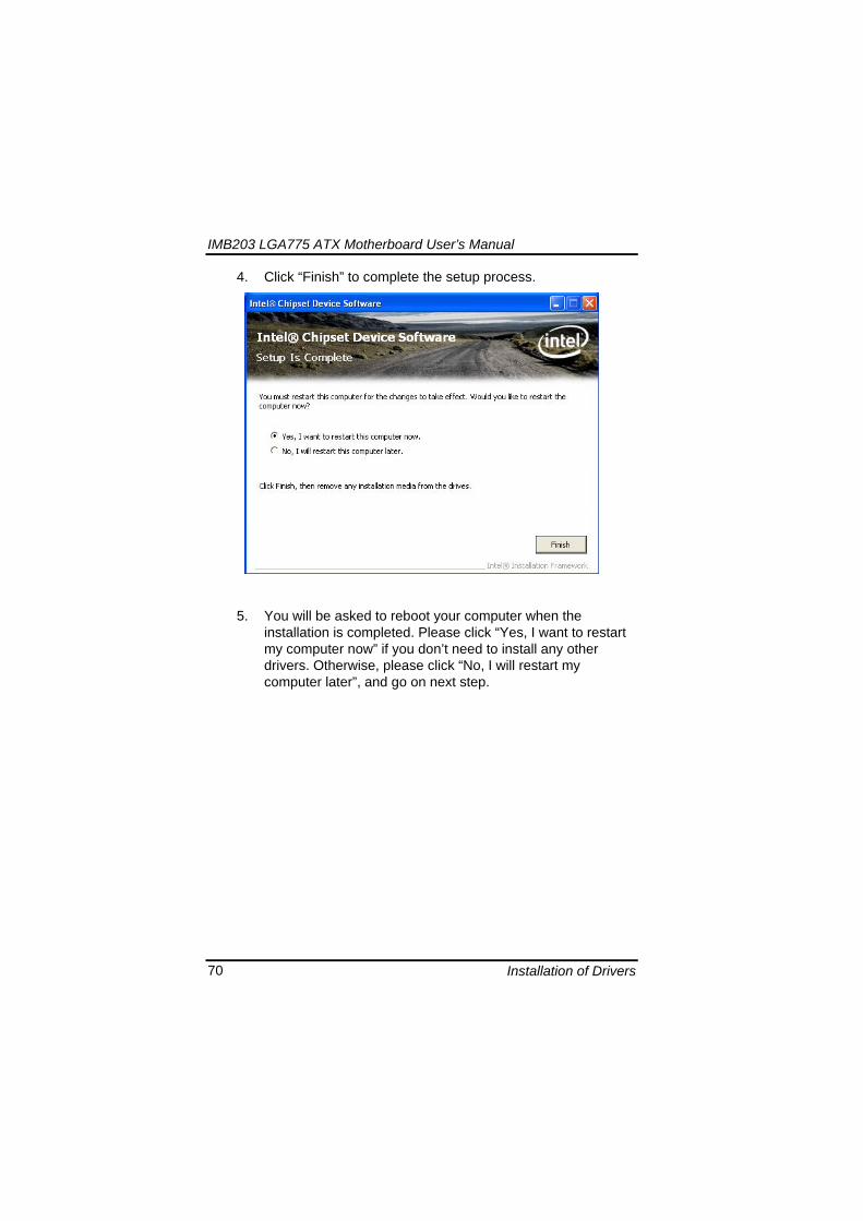
IMB203 LGA775 ATX Motherboard Userrsquos Manual
Installation of Drivers 71
62 Installing VGA Driver 1 Run the SETUPEXE program from the driver directory in
your driver CD Click ldquoNextrdquo to next step
2 An Intelreg License Agreement appears to show you the
important information Click ldquoYesrdquo to next step
IMB203 LGA775 ATX Motherboard Userrsquos Manual
Installation of Drivers 72
3 The message of Readme File Information appears to show you the system requirements and installation information Please click ldquoNextrdquo
4 Please wait while running the following setup operations
When this message appears please click ldquoNextrdquo
IMB203 LGA775 ATX Motherboard Userrsquos Manual
Installation of Drivers 73
5 Click ldquoFinishrdquo to complete the setup process
6 You will be asked to reboot your computer when the installation is completed Please click ldquoYes I want to restart my computer nowrdquo if you donrsquot need to install any other drivers Otherwise please click ldquoNo I will restart my computer laterrdquo and click ldquoFinishrdquo to complete the installation
IMB203 LGA775 ATX Motherboard Userrsquos Manual
Installation of Drivers 74
63 Installing LAN Driver
11 Run the InstallShield Wizard for Network Connections from
the driver directory in your driver CD Click ldquoNextrdquo to next step
IMB203 LGA775 ATX Motherboard Userrsquos Manual
Installation of Drivers 75
12 An Intelreg License Agreement appears to show you the important information Click ldquoYesrdquo to next step
13 A Setup Options window appears that you can select the
program features you want to install
IMB203 LGA775 ATX Motherboard Userrsquos Manual
Installation of Drivers 76
2 Click ldquoInstallrdquo to start the installation
3 Please wait while running the following installation operation
IMB203 LGA775 ATX Motherboard Userrsquos Manual
Installation of Drivers 77
4 Click ldquoFinishrdquo to complete the installation
Note The Driver item [Wake on Directed Packet] default is Enabled under Windows Vista
格式化 字型 (符號) Arial
格式化 字型 (符號) Arial
格式化 字型 斜體 字型色彩 黑色 (符號) Arial 非加寬 緊縮
格式化 字型 斜體 字型色彩 黑色 (符號) Arial 非加寬 緊縮
格式化 字型 (符號) Arial 非加寬 緊縮
IMB203 LGA775 ATX Motherboard Userrsquos Manual
Installation of Drivers 78
64 Installing AUDIO Driver 1 Run the InstallShield Wizard for Realtek High Definition
Audio Driver from the driver directory in your driver CD Click ldquoNextrdquo to next step
IMB203 LGA775 ATX Motherboard Userrsquos Manual
Installation of Drivers 79
2 Click ldquoInstallrdquo to start the installation and wait while running the installation operation
3 Click ldquoFinishrdquo to complete the installation
IMB203 LGA775 ATX Motherboard Userrsquos Manual
Installation of Drivers 80
65 Installing iAMT (Active Management Technology) Driver
Note You must download and properly install the required NET version 35 provided from a separate downloading of the actual FimwareTools kit releases posted on VIP prior to loading the MEILMS Driver stack
651 LMS_SOL Setup
1 Run the setup program to install Intelreg Active Management Technology onto your computer It is strongly recommended that you exit all programs before continuing Click ldquoNextrdquo to next step
格式化 字型 (符號) Arial
格式化 字型 (符號) Arial 非加寬 緊縮
IMB203 LGA775 ATX Motherboard Userrsquos Manual
Installation of Drivers 81
2 An Intelreg license agreement appears that you need to continue the setup program by clicking ldquoYesrdquo to accept the terms
IMB203 LGA775 ATX Motherboard Userrsquos Manual
Installation of Drivers 82
3 Refer to the Readme file below to view the system requirements and installation information Click ldquoNextrdquo to next setup
4 Please wait while running the following installation operation
IMB203 LGA775 ATX Motherboard Userrsquos Manual
Installation of Drivers 83
5 Click ldquoFinishrdquo to complete the installation
IMB203 LGA775 ATX Motherboard Userrsquos Manual
Installation of Drivers 84
652 LMS_SOL_IS Setup
1 Run the setup program to install Intelreg Active Management Technology onto your computer It is strongly recommended that you exit all programs before continuing Click ldquoNextrdquo to next step
IMB203 LGA775 ATX Motherboard Userrsquos Manual
Installation of Drivers 85
2 An Intelreg license agreement appears that you need to continue the setup program by clicking ldquoYesrdquo to accept the terms
IMB203 LGA775 ATX Motherboard Userrsquos Manual
Installation of Drivers 86
3 Refer to the Readme file below to view the system requirements and installation information Click ldquoNextrdquo to next setup
4 Please wait while running the following installation operation
IMB203 LGA775 ATX Motherboard Userrsquos Manual
Installation of Drivers 87
5 Click ldquoFinishrdquo to complete the installation
IMB203 LGA775 ATX Motherboard Userrsquos Manual
Installation of Drivers 88
66 Installing MEI (Management Engine Interface) Driver
Note You must download and properly install the required NET version 35 provided from a separate downloading of the actual FimwareTools kit releases posted on VIP prior to loading the MEILMS Driver stack
1 Run the setup program to install Intelreg Management Engine
Interface onto your computer It is strongly recommended that you exit all programs before continuing Click ldquoNextrdquo to next step
格式化 字型 (符號) Arial
格式化 字型 (符號) Arial 非加寬 緊縮
IMB203 LGA775 ATX Motherboard Userrsquos Manual
Installation of Drivers 89
2 An Intelreg license agreement appears that you need to continue the setup program by clicking ldquoYesrdquo to accept the terms
IMB203 LGA775 ATX Motherboard Userrsquos Manual
Installation of Drivers 90
3 Refer to the Readme file below to view the system requirements and installation information Click ldquoNextrdquo to next setup
4 Please wait while running the following installation operation
IMB203 LGA775 ATX Motherboard Userrsquos Manual
Installation of Drivers 91
5 Click ldquoFinishrdquo to complete the installation
IMB203 LGA775 ATX Motherboard Userrsquos Manual
Installation of Drivers 92
MEMO
IMB203 LGA775 ATX Motherboard Userrsquos Manual
Watchdog Timer 93
APPENDIX A WATCHDOG TIMER
Watchdog Timer Setting After the system stops working for a while it can be auto-reset by the Watchdog Timer The integrated Watchdog Timer can be set up in the system reset mode by program
Using the Watchdog Function Start darr Un-Lock WDT O 2E 87 Un-lock super IO
O 2E 87 Un-lock super IO darr Set WDT Function O 2E 2D O 2F 20 Select Logic device O 2E 07 O 2F 08 darr Activate WDT O 2E 30
O 2F 01 Set Second or Minute O 2E F5
O 2F N N=00 or 08(See below table) darr Set base timer O 2E F6
O 2F M=000102hellipFF(Hex) Value=0 to 255 darr WDT counting
re-set timer O 2E F6
O 2F M M=000102hellipFF(See below table) darr
格式化
格式化 項目符號及編號
格式化 項目符號及編號
格式化 字型 8 點 字型色彩黑色
格式化 字型 8 點 字型色彩黑色
格式化 定位點 1257 字元左 + 不在 1012 字元 + 1386字元
格式化 字型 8 點 字型色彩黑色
格式化 定位點 1257 字元左 + 不在 134 字元 + 1362字元
格式化 字型色彩 黑色
格式化 字型色彩 黑色
刪除
IMB203 LGA775 ATX Motherboard Userrsquos Manual
Watchdog Timer 94
IF No re-set timer WDT time-out generate RESET IF to disable WDT O 2E 30
O 2F 00 Can be disable at any time
N=00
M= 00h Time-out Disable 01h Time-out occurs after 1 second 02h Time-out occurs after 2 second 03h Time-out occurs after 3 second helliphelliphelliphelliphelliphelliphelliphelliphellip FFh Time-out occurs after 255 second
N=08
M= 00h Time-out Disable 01h Time-out occurs after 1 minute 02h Time-out occurs after 2 minutes 03h Time-out occurs after 3 minutes helliphelliphelliphelliphelliphelliphelliphelliphellip
FFh Time-out occurs after 255 minutes
格式化 字型色彩 黑色
格式化 字型色彩 黑色
IMB203 LGA775 ATX Motherboard Userrsquos Manual
PCI IRQ Routing 95
APPENDIX B PCI IRQ ROUTING
PICMG PCI IRQ Routing
Device ID Slot Int
PCI Slot 0 31 0 BCDA PCI Slot 1 30 1 CDAB PCI Slot 2 29 2 DABC PCI Slot 3 28 3 ABCD
IMB203 LGA775 ATX Motherboard Userrsquos Manual
PCI IRQ Routing 96
MEMO
IMB203 LGA775 ATX Motherboard Userrsquos Manual
Configuring SATA for RAID Function 97
APPENDIX C CONFIGURING SATA FOR RAID
FUNCTION
Configuring SATA Hard Drive(s) for RAID Function (Controller IntelregICH10DODO DH only) Please follow up the steps below to configure SATA hard drive(s) (1) Install SATA hard drive(s) in your system (2) Enter the BIOS Setup to configure SATA controller mode and boot
sequence (3) Configure RAID by the RAID BIOS (4) Install the SATA controller driver during the OS installation Before you begin the SATA configuration please prepare (a) Two SATA hard drives (to ensure optimal performance it is
recommended that you use two hard drives with identical model and capacity) If you do not want to create RAID with the SATA controller you may prepare only one hard drive
(b) An empty formatted floppy disk (c) Windows XP setup disk (1) Installing SATA hard drive(s) in your system
Connect one end of the SATA signal cable to the rear of the SATA hard drive and the other end to available SATA port(s) on the board Then connect the power connector of power supply to the hard drive
(2) Configuring SATA controller mode and boot sequence by the BIOS Setup You have to make sure whether the SATA controller is configured correctly by system BIOS Setup and set up BIOS boot sequence for the SATA hard drive(s)
IMB203 LGA775 ATX Motherboard Userrsquos Manual
Configuring SATA for RAID Function 98
(2)-1-1 Turn on your system and then press the Del button to enter BIOS Setup during running POST (Power-On Self Test) If you want to create RAID just go to the Advanced Settings menuIDE configuration select the Configure SATA1 as and press ltEntergt for more options
IMB203 LGA775 ATX Motherboard Userrsquos Manual
Configuring SATA for RAID Function 99
(2)-1-2 A list of options appears please select RAID
IMB203 LGA775 ATX Motherboard Userrsquos Manual
Configuring SATA for RAID Function 100
(2)-2 Set CDROM for First Boot Device under the Boot Settings menu to boot CD-ROM after system restarts
(2)-3 Save and exit the BIOS Setup
IMB203 LGA775 ATX Motherboard Userrsquos Manual
Configuring SATA for RAID Function 101
(3) Configuring RAID by the RAID BIOS Enter the RAID BIOS setup utility to configure a RAID array Skip this step and proceed to Section 4 if you do not want to create a RAID (3)-1 After the POST memory testing and before the operating
system booting a message Press ltCtrl-Igt to enter Configuration Utility shows up accordingly press ltCTRL+ Igt to enter the RAID BIOS setup utility
(3)-2 After you press ltCTRL+ Igt the Create RAID Volume screen will appear If you want to create a RAID array select the Create RAID Volume option in the Main Menu and press ENTER
IMB203 LGA775 ATX Motherboard Userrsquos Manual
Configuring SATA for RAID Function 102
(3)-3-1 After entering the CREATE VOLUME MENU screen you can type the disk array name with 1~16 letters (letters cannot be special characters) in the item ldquoNamerdquo
(3)-3-2 When finished press ENTER to select a RAID level There are three RAID levels RAID0 RAID1 and RAID5 amp RAID10 Select a RAID level and press ENTER
IMB203 LGA775 ATX Motherboard Userrsquos Manual
Configuring SATA for RAID Function 103
(3)-4 Set the stripe block size The KB is the standard unit of stripe block size The stripe block size can be 4KB to 128KB After the setting press ENTER for the array capacity
(3)-5 After setting all the items on the menu select Create Volume
and press ENTER to start creating the RAID array
IMB203 LGA775 ATX Motherboard Userrsquos Manual
Configuring SATA for RAID Function 104
(3)-6 When prompting the confirmation press ldquoYldquo to create this volume or ldquoNldquo to cancel the creation
After the creation is completed you can see detailed information about the RAID Array in the DISKVOLUME INFORMATION section including RAID mode disk block size disk name and disk capacity etc
IMB203 LGA775 ATX Motherboard Userrsquos Manual
Configuring SATA for RAID Function 105
Delete RAID Volume If you want to delete a RAID volume select the Delete RAID Volume option in Main Menu Press ENTER and follow on-screen instructions
Please press [ESC] to exit the RAID BIOS utility Now you can proceed to install a SATA driver controller and the operating system
IMB203 LGA775 ATX Motherboard Userrsquos Manual
Configuring SATA for RAID Function 106
(4) Making a SATA Driver Disk To install the operating system onto a serial ATA hard disk successfully you need to install the SATA controller driver during the OS installation Without the driver the hard disk may not be recognized during the Windows setup process First of all please format a blank floppy disk Secondly follow up these steps below to produce a SATA driver disk Users can insert the Driver CD and the formatted blank floppy disk in another system And then please copy all of file of the f6flpy32 folder in the Driver CD to a floppy disk Note Please copy all of file of the f6flpy64 folder if installing 64-bit
Windows Operating System
IMB203 LGA775 ATX Motherboard Userrsquos Manual
Configuring SATA for RAID Function 107
(5) Installing the SATA controller driver during the OS installation Now the SATA driver disk is ready and BIOS settings configured you can proceed to install Windows 2000XP onto your SATA hard drive using the SATA driver Here is an example for Windows XP installation (5)-1 Restart your system to boot the Windows 2000XP Setup disk
and press F6 button as soon as you see the message Press F6 if you need to install a 3rd party SCSI or RAID driver After pressing the F6 button there will be a few moments for some files being loaded before next screen appears
IMB203 LGA775 ATX Motherboard Userrsquos Manual
Configuring SATA for RAID Function 108
(5)-2 When you see the screen below insert the floppy disk containing the SATA driver and press ldquoSrdquo
(5)-3 If the Setup correctly recognizes the driver of the floppy disk
a controller menu will appear below Use the ARROW keys to select Intel(R) ICH8RICH9RICH10RDO SATA RAID Controller and press ENTER Then it will begin to load the SATA driver from the floppy disk
IMB203 LGA775 ATX Motherboard Userrsquos Manual
Configuring SATA for RAID Function 109
Note If a message on the screen saying that one or some file(s) cannot be found please check the floppy disk or copy the correct SATA driver again from the driver CD
IMB203 LGA775 ATX Motherboard Userrsquos Manual
Configuring SATA for RAID Function 110
MEMO
IMB203 LGA775 ATX Motherboard Userrsquos Manual
iAMT Settings 111
APPENDIX D iAMT SETTINGS
The Intelreg Active Management Technology (Intelreg iAMT) has decreased a major barrier to IT efficiency that uses built-in platform capabilities and popular third-party management and security applications to allow IT a better discovering healing and protection their networked computing assets In order to utilize Intel iAMT you must enter the ME BIOS (CTRL + P during system startup) change the ME BIOS password and then select ldquoIntelreg iAMTrdquo as the manageability feature
D1 Entering MEBx 1 You must go to BIOS TO start iAMT function 2 Exit from BIOS after starting iAMT and press Ctrl+P to enter MEBx Setting
It is better to press Ctrl+P before the screen popping out
格式化
IMB203 LGA775 ATX Motherboard Userrsquos Manual
iAMT Settings 112
D2 Set amp Change Password 1 You will be asked to set a password when first log in The default
password is lsquoadminrsquo
2 You will be asked to change the password before setting ME
Change Password
IMB203 LGA775 ATX Motherboard Userrsquos Manual
iAMT Settings 113
3 You must confirm your new password while revising (as Remark 1)
Remark 1 The new password must contain (example 11qqQQ) (default value)
Eight characters
One upper case
One lower case
One number
One special symbol such as $ or
( excepted)
Underline ( _ ) and space are valid characters for password but they wonrsquot make higher complexity
IMB203 LGA775 ATX Motherboard Userrsquos Manual
iAMT Settings 114
D3 Intelreg iAMT Settings 1 Select Intelreg iAMT Configuration and press ltENTERgt
2 Key in the Host Name If Intelreg iAMT set to lsquoDHCPlsquo the Host name must be identical to the operating system mechanic
IMB203 LGA775 ATX Motherboard Userrsquos Manual
iAMT Settings 115
3 Select TCPIP to get into Network interface and set it to lsquoENABLEDrsquo into DHCP Mode and set it to lsquoDISABLEDrsquo (as Remark 2) into Domain name and set the Intel Management Engine domain name such as lsquoAMTintelcomrsquo
(3-1)
(3-2)
IMB203 LGA775 ATX Motherboard Userrsquos Manual
iAMT Settings 116
Remark 2 DHCP Mode lsquoDISABLEDlsquo if DHCP Mode is disabled you can make the following settings
IP address
Subnet mask
IMB203 LGA775 ATX Motherboard Userrsquos Manual
iAMT Settings 117
Default Gateway address
Preferred DNS address
IMB203 LGA775 ATX Motherboard Userrsquos Manual
iAMT Settings 118
Alternate DNS address
Domain name
4 Exit from MEBx after completing the iAMT settings
IMB203 LGA775 ATX Motherboard Userrsquos Manual
iAMT Settings 119
D4 iAMT Web Console 1 From a web browser please type http(IP ADDRESS)16992
which connects to iAMT Web Example http1014021416992
2 To log on you will be required to type in username and password
for access to the Web
USER admin (default value)
PASS (MEBx password)
IMB203 LGA775 ATX Motherboard Userrsquos Manual
iAMT Settings 120
3 Enter the iAMT Web
4 Click Remote Control and select commands on the right side
IMB203 LGA775 ATX Motherboard Userrsquos Manual
iAMT Settings 121
5 When you have finished using the iAMT Web console close the Web browser
IMB203 LGA775 ATX Motherboard Userrsquos Manual
iAMT Settings 122
MEMO
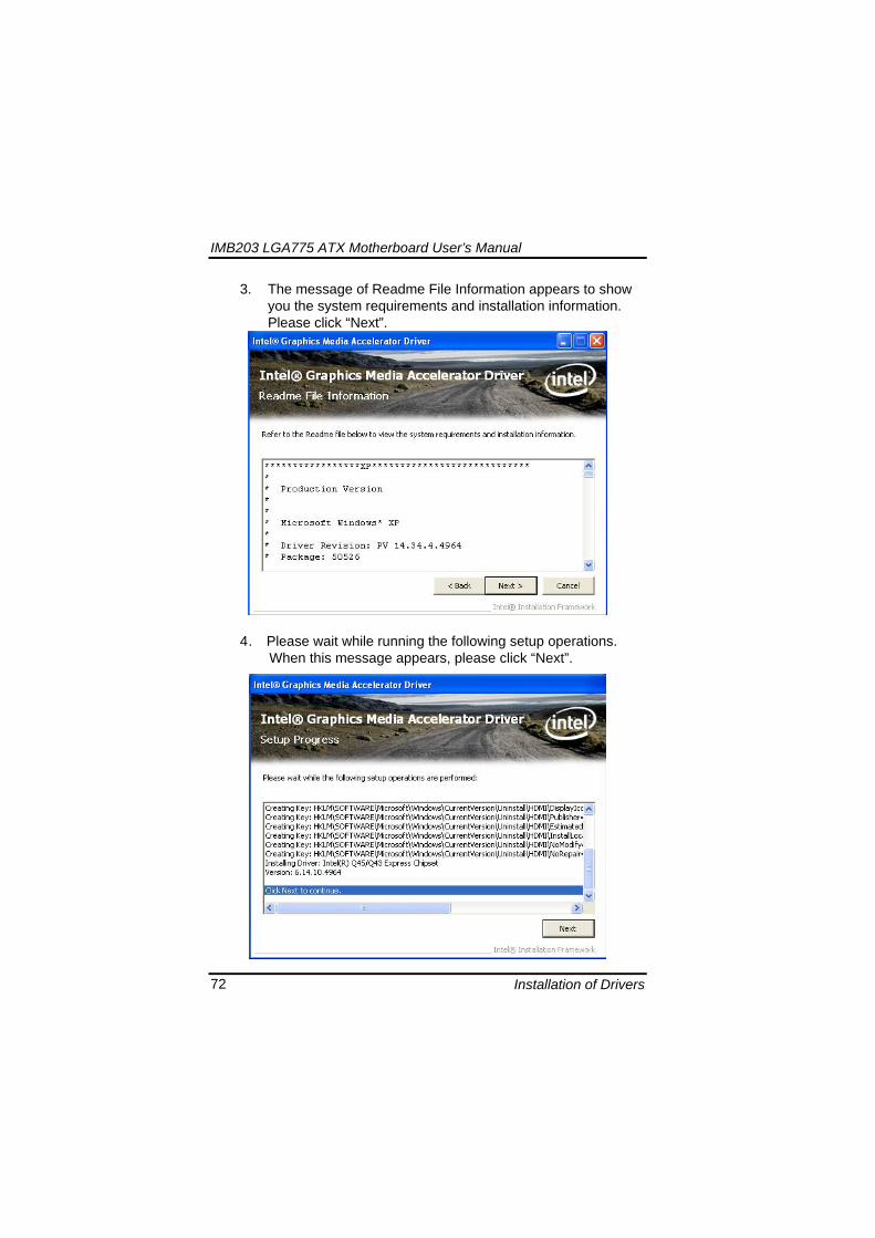
IMB203 LGA775 ATX Motherboard Userrsquos Manual
Installation of Drivers 73
5 Click ldquoFinishrdquo to complete the setup process
6 You will be asked to reboot your computer when the installation is completed Please click ldquoYes I want to restart my computer nowrdquo if you donrsquot need to install any other drivers Otherwise please click ldquoNo I will restart my computer laterrdquo and click ldquoFinishrdquo to complete the installation
IMB203 LGA775 ATX Motherboard Userrsquos Manual
Installation of Drivers 74
63 Installing LAN Driver
11 Run the InstallShield Wizard for Network Connections from
the driver directory in your driver CD Click ldquoNextrdquo to next step
IMB203 LGA775 ATX Motherboard Userrsquos Manual
Installation of Drivers 75
12 An Intelreg License Agreement appears to show you the important information Click ldquoYesrdquo to next step
13 A Setup Options window appears that you can select the
program features you want to install
IMB203 LGA775 ATX Motherboard Userrsquos Manual
Installation of Drivers 76
2 Click ldquoInstallrdquo to start the installation
3 Please wait while running the following installation operation
IMB203 LGA775 ATX Motherboard Userrsquos Manual
Installation of Drivers 77
4 Click ldquoFinishrdquo to complete the installation
Note The Driver item [Wake on Directed Packet] default is Enabled under Windows Vista
格式化 字型 (符號) Arial
格式化 字型 (符號) Arial
格式化 字型 斜體 字型色彩 黑色 (符號) Arial 非加寬 緊縮
格式化 字型 斜體 字型色彩 黑色 (符號) Arial 非加寬 緊縮
格式化 字型 (符號) Arial 非加寬 緊縮
IMB203 LGA775 ATX Motherboard Userrsquos Manual
Installation of Drivers 78
64 Installing AUDIO Driver 1 Run the InstallShield Wizard for Realtek High Definition
Audio Driver from the driver directory in your driver CD Click ldquoNextrdquo to next step
IMB203 LGA775 ATX Motherboard Userrsquos Manual
Installation of Drivers 79
2 Click ldquoInstallrdquo to start the installation and wait while running the installation operation
3 Click ldquoFinishrdquo to complete the installation
IMB203 LGA775 ATX Motherboard Userrsquos Manual
Installation of Drivers 80
65 Installing iAMT (Active Management Technology) Driver
Note You must download and properly install the required NET version 35 provided from a separate downloading of the actual FimwareTools kit releases posted on VIP prior to loading the MEILMS Driver stack
651 LMS_SOL Setup
1 Run the setup program to install Intelreg Active Management Technology onto your computer It is strongly recommended that you exit all programs before continuing Click ldquoNextrdquo to next step
格式化 字型 (符號) Arial
格式化 字型 (符號) Arial 非加寬 緊縮
IMB203 LGA775 ATX Motherboard Userrsquos Manual
Installation of Drivers 81
2 An Intelreg license agreement appears that you need to continue the setup program by clicking ldquoYesrdquo to accept the terms
IMB203 LGA775 ATX Motherboard Userrsquos Manual
Installation of Drivers 82
3 Refer to the Readme file below to view the system requirements and installation information Click ldquoNextrdquo to next setup
4 Please wait while running the following installation operation
IMB203 LGA775 ATX Motherboard Userrsquos Manual
Installation of Drivers 83
5 Click ldquoFinishrdquo to complete the installation
IMB203 LGA775 ATX Motherboard Userrsquos Manual
Installation of Drivers 84
652 LMS_SOL_IS Setup
1 Run the setup program to install Intelreg Active Management Technology onto your computer It is strongly recommended that you exit all programs before continuing Click ldquoNextrdquo to next step
IMB203 LGA775 ATX Motherboard Userrsquos Manual
Installation of Drivers 85
2 An Intelreg license agreement appears that you need to continue the setup program by clicking ldquoYesrdquo to accept the terms
IMB203 LGA775 ATX Motherboard Userrsquos Manual
Installation of Drivers 86
3 Refer to the Readme file below to view the system requirements and installation information Click ldquoNextrdquo to next setup
4 Please wait while running the following installation operation
IMB203 LGA775 ATX Motherboard Userrsquos Manual
Installation of Drivers 87
5 Click ldquoFinishrdquo to complete the installation
IMB203 LGA775 ATX Motherboard Userrsquos Manual
Installation of Drivers 88
66 Installing MEI (Management Engine Interface) Driver
Note You must download and properly install the required NET version 35 provided from a separate downloading of the actual FimwareTools kit releases posted on VIP prior to loading the MEILMS Driver stack
1 Run the setup program to install Intelreg Management Engine
Interface onto your computer It is strongly recommended that you exit all programs before continuing Click ldquoNextrdquo to next step
格式化 字型 (符號) Arial
格式化 字型 (符號) Arial 非加寬 緊縮
IMB203 LGA775 ATX Motherboard Userrsquos Manual
Installation of Drivers 89
2 An Intelreg license agreement appears that you need to continue the setup program by clicking ldquoYesrdquo to accept the terms
IMB203 LGA775 ATX Motherboard Userrsquos Manual
Installation of Drivers 90
3 Refer to the Readme file below to view the system requirements and installation information Click ldquoNextrdquo to next setup
4 Please wait while running the following installation operation
IMB203 LGA775 ATX Motherboard Userrsquos Manual
Installation of Drivers 91
5 Click ldquoFinishrdquo to complete the installation
IMB203 LGA775 ATX Motherboard Userrsquos Manual
Installation of Drivers 92
MEMO
IMB203 LGA775 ATX Motherboard Userrsquos Manual
Watchdog Timer 93
APPENDIX A WATCHDOG TIMER
Watchdog Timer Setting After the system stops working for a while it can be auto-reset by the Watchdog Timer The integrated Watchdog Timer can be set up in the system reset mode by program
Using the Watchdog Function Start darr Un-Lock WDT O 2E 87 Un-lock super IO
O 2E 87 Un-lock super IO darr Set WDT Function O 2E 2D O 2F 20 Select Logic device O 2E 07 O 2F 08 darr Activate WDT O 2E 30
O 2F 01 Set Second or Minute O 2E F5
O 2F N N=00 or 08(See below table) darr Set base timer O 2E F6
O 2F M=000102hellipFF(Hex) Value=0 to 255 darr WDT counting
re-set timer O 2E F6
O 2F M M=000102hellipFF(See below table) darr
格式化
格式化 項目符號及編號
格式化 項目符號及編號
格式化 字型 8 點 字型色彩黑色
格式化 字型 8 點 字型色彩黑色
格式化 定位點 1257 字元左 + 不在 1012 字元 + 1386字元
格式化 字型 8 點 字型色彩黑色
格式化 定位點 1257 字元左 + 不在 134 字元 + 1362字元
格式化 字型色彩 黑色
格式化 字型色彩 黑色
刪除
IMB203 LGA775 ATX Motherboard Userrsquos Manual
Watchdog Timer 94
IF No re-set timer WDT time-out generate RESET IF to disable WDT O 2E 30
O 2F 00 Can be disable at any time
N=00
M= 00h Time-out Disable 01h Time-out occurs after 1 second 02h Time-out occurs after 2 second 03h Time-out occurs after 3 second helliphelliphelliphelliphelliphelliphelliphelliphellip FFh Time-out occurs after 255 second
N=08
M= 00h Time-out Disable 01h Time-out occurs after 1 minute 02h Time-out occurs after 2 minutes 03h Time-out occurs after 3 minutes helliphelliphelliphelliphelliphelliphelliphelliphellip
FFh Time-out occurs after 255 minutes
格式化 字型色彩 黑色
格式化 字型色彩 黑色
IMB203 LGA775 ATX Motherboard Userrsquos Manual
PCI IRQ Routing 95
APPENDIX B PCI IRQ ROUTING
PICMG PCI IRQ Routing
Device ID Slot Int
PCI Slot 0 31 0 BCDA PCI Slot 1 30 1 CDAB PCI Slot 2 29 2 DABC PCI Slot 3 28 3 ABCD
IMB203 LGA775 ATX Motherboard Userrsquos Manual
PCI IRQ Routing 96
MEMO
IMB203 LGA775 ATX Motherboard Userrsquos Manual
Configuring SATA for RAID Function 97
APPENDIX C CONFIGURING SATA FOR RAID
FUNCTION
Configuring SATA Hard Drive(s) for RAID Function (Controller IntelregICH10DODO DH only) Please follow up the steps below to configure SATA hard drive(s) (1) Install SATA hard drive(s) in your system (2) Enter the BIOS Setup to configure SATA controller mode and boot
sequence (3) Configure RAID by the RAID BIOS (4) Install the SATA controller driver during the OS installation Before you begin the SATA configuration please prepare (a) Two SATA hard drives (to ensure optimal performance it is
recommended that you use two hard drives with identical model and capacity) If you do not want to create RAID with the SATA controller you may prepare only one hard drive
(b) An empty formatted floppy disk (c) Windows XP setup disk (1) Installing SATA hard drive(s) in your system
Connect one end of the SATA signal cable to the rear of the SATA hard drive and the other end to available SATA port(s) on the board Then connect the power connector of power supply to the hard drive
(2) Configuring SATA controller mode and boot sequence by the BIOS Setup You have to make sure whether the SATA controller is configured correctly by system BIOS Setup and set up BIOS boot sequence for the SATA hard drive(s)
IMB203 LGA775 ATX Motherboard Userrsquos Manual
Configuring SATA for RAID Function 98
(2)-1-1 Turn on your system and then press the Del button to enter BIOS Setup during running POST (Power-On Self Test) If you want to create RAID just go to the Advanced Settings menuIDE configuration select the Configure SATA1 as and press ltEntergt for more options
IMB203 LGA775 ATX Motherboard Userrsquos Manual
Configuring SATA for RAID Function 99
(2)-1-2 A list of options appears please select RAID
IMB203 LGA775 ATX Motherboard Userrsquos Manual
Configuring SATA for RAID Function 100
(2)-2 Set CDROM for First Boot Device under the Boot Settings menu to boot CD-ROM after system restarts
(2)-3 Save and exit the BIOS Setup
IMB203 LGA775 ATX Motherboard Userrsquos Manual
Configuring SATA for RAID Function 101
(3) Configuring RAID by the RAID BIOS Enter the RAID BIOS setup utility to configure a RAID array Skip this step and proceed to Section 4 if you do not want to create a RAID (3)-1 After the POST memory testing and before the operating
system booting a message Press ltCtrl-Igt to enter Configuration Utility shows up accordingly press ltCTRL+ Igt to enter the RAID BIOS setup utility
(3)-2 After you press ltCTRL+ Igt the Create RAID Volume screen will appear If you want to create a RAID array select the Create RAID Volume option in the Main Menu and press ENTER
IMB203 LGA775 ATX Motherboard Userrsquos Manual
Configuring SATA for RAID Function 102
(3)-3-1 After entering the CREATE VOLUME MENU screen you can type the disk array name with 1~16 letters (letters cannot be special characters) in the item ldquoNamerdquo
(3)-3-2 When finished press ENTER to select a RAID level There are three RAID levels RAID0 RAID1 and RAID5 amp RAID10 Select a RAID level and press ENTER
IMB203 LGA775 ATX Motherboard Userrsquos Manual
Configuring SATA for RAID Function 103
(3)-4 Set the stripe block size The KB is the standard unit of stripe block size The stripe block size can be 4KB to 128KB After the setting press ENTER for the array capacity
(3)-5 After setting all the items on the menu select Create Volume
and press ENTER to start creating the RAID array
IMB203 LGA775 ATX Motherboard Userrsquos Manual
Configuring SATA for RAID Function 104
(3)-6 When prompting the confirmation press ldquoYldquo to create this volume or ldquoNldquo to cancel the creation
After the creation is completed you can see detailed information about the RAID Array in the DISKVOLUME INFORMATION section including RAID mode disk block size disk name and disk capacity etc
IMB203 LGA775 ATX Motherboard Userrsquos Manual
Configuring SATA for RAID Function 105
Delete RAID Volume If you want to delete a RAID volume select the Delete RAID Volume option in Main Menu Press ENTER and follow on-screen instructions
Please press [ESC] to exit the RAID BIOS utility Now you can proceed to install a SATA driver controller and the operating system
IMB203 LGA775 ATX Motherboard Userrsquos Manual
Configuring SATA for RAID Function 106
(4) Making a SATA Driver Disk To install the operating system onto a serial ATA hard disk successfully you need to install the SATA controller driver during the OS installation Without the driver the hard disk may not be recognized during the Windows setup process First of all please format a blank floppy disk Secondly follow up these steps below to produce a SATA driver disk Users can insert the Driver CD and the formatted blank floppy disk in another system And then please copy all of file of the f6flpy32 folder in the Driver CD to a floppy disk Note Please copy all of file of the f6flpy64 folder if installing 64-bit
Windows Operating System
IMB203 LGA775 ATX Motherboard Userrsquos Manual
Configuring SATA for RAID Function 107
(5) Installing the SATA controller driver during the OS installation Now the SATA driver disk is ready and BIOS settings configured you can proceed to install Windows 2000XP onto your SATA hard drive using the SATA driver Here is an example for Windows XP installation (5)-1 Restart your system to boot the Windows 2000XP Setup disk
and press F6 button as soon as you see the message Press F6 if you need to install a 3rd party SCSI or RAID driver After pressing the F6 button there will be a few moments for some files being loaded before next screen appears
IMB203 LGA775 ATX Motherboard Userrsquos Manual
Configuring SATA for RAID Function 108
(5)-2 When you see the screen below insert the floppy disk containing the SATA driver and press ldquoSrdquo
(5)-3 If the Setup correctly recognizes the driver of the floppy disk
a controller menu will appear below Use the ARROW keys to select Intel(R) ICH8RICH9RICH10RDO SATA RAID Controller and press ENTER Then it will begin to load the SATA driver from the floppy disk
IMB203 LGA775 ATX Motherboard Userrsquos Manual
Configuring SATA for RAID Function 109
Note If a message on the screen saying that one or some file(s) cannot be found please check the floppy disk or copy the correct SATA driver again from the driver CD
IMB203 LGA775 ATX Motherboard Userrsquos Manual
Configuring SATA for RAID Function 110
MEMO
IMB203 LGA775 ATX Motherboard Userrsquos Manual
iAMT Settings 111
APPENDIX D iAMT SETTINGS
The Intelreg Active Management Technology (Intelreg iAMT) has decreased a major barrier to IT efficiency that uses built-in platform capabilities and popular third-party management and security applications to allow IT a better discovering healing and protection their networked computing assets In order to utilize Intel iAMT you must enter the ME BIOS (CTRL + P during system startup) change the ME BIOS password and then select ldquoIntelreg iAMTrdquo as the manageability feature
D1 Entering MEBx 1 You must go to BIOS TO start iAMT function 2 Exit from BIOS after starting iAMT and press Ctrl+P to enter MEBx Setting
It is better to press Ctrl+P before the screen popping out
格式化
IMB203 LGA775 ATX Motherboard Userrsquos Manual
iAMT Settings 112
D2 Set amp Change Password 1 You will be asked to set a password when first log in The default
password is lsquoadminrsquo
2 You will be asked to change the password before setting ME
Change Password
IMB203 LGA775 ATX Motherboard Userrsquos Manual
iAMT Settings 113
3 You must confirm your new password while revising (as Remark 1)
Remark 1 The new password must contain (example 11qqQQ) (default value)
Eight characters
One upper case
One lower case
One number
One special symbol such as $ or
( excepted)
Underline ( _ ) and space are valid characters for password but they wonrsquot make higher complexity
IMB203 LGA775 ATX Motherboard Userrsquos Manual
iAMT Settings 114
D3 Intelreg iAMT Settings 1 Select Intelreg iAMT Configuration and press ltENTERgt
2 Key in the Host Name If Intelreg iAMT set to lsquoDHCPlsquo the Host name must be identical to the operating system mechanic
IMB203 LGA775 ATX Motherboard Userrsquos Manual
iAMT Settings 115
3 Select TCPIP to get into Network interface and set it to lsquoENABLEDrsquo into DHCP Mode and set it to lsquoDISABLEDrsquo (as Remark 2) into Domain name and set the Intel Management Engine domain name such as lsquoAMTintelcomrsquo
(3-1)
(3-2)
IMB203 LGA775 ATX Motherboard Userrsquos Manual
iAMT Settings 116
Remark 2 DHCP Mode lsquoDISABLEDlsquo if DHCP Mode is disabled you can make the following settings
IP address
Subnet mask
IMB203 LGA775 ATX Motherboard Userrsquos Manual
iAMT Settings 117
Default Gateway address
Preferred DNS address
IMB203 LGA775 ATX Motherboard Userrsquos Manual
iAMT Settings 118
Alternate DNS address
Domain name
4 Exit from MEBx after completing the iAMT settings
IMB203 LGA775 ATX Motherboard Userrsquos Manual
iAMT Settings 119
D4 iAMT Web Console 1 From a web browser please type http(IP ADDRESS)16992
which connects to iAMT Web Example http1014021416992
2 To log on you will be required to type in username and password
for access to the Web
USER admin (default value)
PASS (MEBx password)
IMB203 LGA775 ATX Motherboard Userrsquos Manual
iAMT Settings 120
3 Enter the iAMT Web
4 Click Remote Control and select commands on the right side
IMB203 LGA775 ATX Motherboard Userrsquos Manual
iAMT Settings 121
5 When you have finished using the iAMT Web console close the Web browser
IMB203 LGA775 ATX Motherboard Userrsquos Manual
iAMT Settings 122
MEMO
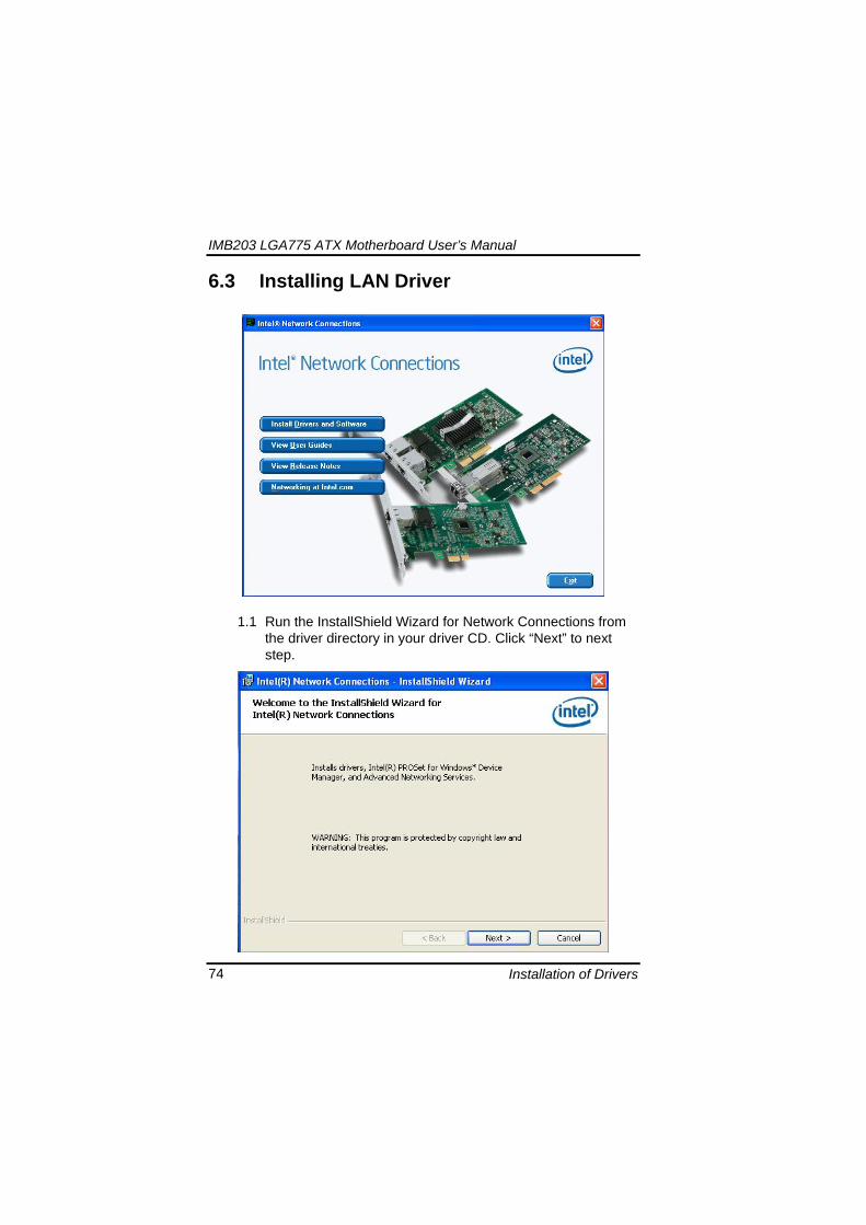
IMB203 LGA775 ATX Motherboard Userrsquos Manual
Installation of Drivers 77
4 Click ldquoFinishrdquo to complete the installation
Note The Driver item [Wake on Directed Packet] default is Enabled under Windows Vista
格式化 字型 (符號) Arial
格式化 字型 (符號) Arial
格式化 字型 斜體 字型色彩 黑色 (符號) Arial 非加寬 緊縮
格式化 字型 斜體 字型色彩 黑色 (符號) Arial 非加寬 緊縮
格式化 字型 (符號) Arial 非加寬 緊縮
IMB203 LGA775 ATX Motherboard Userrsquos Manual
Installation of Drivers 78
64 Installing AUDIO Driver 1 Run the InstallShield Wizard for Realtek High Definition
Audio Driver from the driver directory in your driver CD Click ldquoNextrdquo to next step
IMB203 LGA775 ATX Motherboard Userrsquos Manual
Installation of Drivers 79
2 Click ldquoInstallrdquo to start the installation and wait while running the installation operation
3 Click ldquoFinishrdquo to complete the installation
IMB203 LGA775 ATX Motherboard Userrsquos Manual
Installation of Drivers 80
65 Installing iAMT (Active Management Technology) Driver
Note You must download and properly install the required NET version 35 provided from a separate downloading of the actual FimwareTools kit releases posted on VIP prior to loading the MEILMS Driver stack
651 LMS_SOL Setup
1 Run the setup program to install Intelreg Active Management Technology onto your computer It is strongly recommended that you exit all programs before continuing Click ldquoNextrdquo to next step
格式化 字型 (符號) Arial
格式化 字型 (符號) Arial 非加寬 緊縮
IMB203 LGA775 ATX Motherboard Userrsquos Manual
Installation of Drivers 81
2 An Intelreg license agreement appears that you need to continue the setup program by clicking ldquoYesrdquo to accept the terms
IMB203 LGA775 ATX Motherboard Userrsquos Manual
Installation of Drivers 82
3 Refer to the Readme file below to view the system requirements and installation information Click ldquoNextrdquo to next setup
4 Please wait while running the following installation operation
IMB203 LGA775 ATX Motherboard Userrsquos Manual
Installation of Drivers 83
5 Click ldquoFinishrdquo to complete the installation
IMB203 LGA775 ATX Motherboard Userrsquos Manual
Installation of Drivers 84
652 LMS_SOL_IS Setup
1 Run the setup program to install Intelreg Active Management Technology onto your computer It is strongly recommended that you exit all programs before continuing Click ldquoNextrdquo to next step
IMB203 LGA775 ATX Motherboard Userrsquos Manual
Installation of Drivers 85
2 An Intelreg license agreement appears that you need to continue the setup program by clicking ldquoYesrdquo to accept the terms
IMB203 LGA775 ATX Motherboard Userrsquos Manual
Installation of Drivers 86
3 Refer to the Readme file below to view the system requirements and installation information Click ldquoNextrdquo to next setup
4 Please wait while running the following installation operation
IMB203 LGA775 ATX Motherboard Userrsquos Manual
Installation of Drivers 87
5 Click ldquoFinishrdquo to complete the installation
IMB203 LGA775 ATX Motherboard Userrsquos Manual
Installation of Drivers 88
66 Installing MEI (Management Engine Interface) Driver
Note You must download and properly install the required NET version 35 provided from a separate downloading of the actual FimwareTools kit releases posted on VIP prior to loading the MEILMS Driver stack
1 Run the setup program to install Intelreg Management Engine
Interface onto your computer It is strongly recommended that you exit all programs before continuing Click ldquoNextrdquo to next step
格式化 字型 (符號) Arial
格式化 字型 (符號) Arial 非加寬 緊縮
IMB203 LGA775 ATX Motherboard Userrsquos Manual
Installation of Drivers 89
2 An Intelreg license agreement appears that you need to continue the setup program by clicking ldquoYesrdquo to accept the terms
IMB203 LGA775 ATX Motherboard Userrsquos Manual
Installation of Drivers 90
3 Refer to the Readme file below to view the system requirements and installation information Click ldquoNextrdquo to next setup
4 Please wait while running the following installation operation
IMB203 LGA775 ATX Motherboard Userrsquos Manual
Installation of Drivers 91
5 Click ldquoFinishrdquo to complete the installation
IMB203 LGA775 ATX Motherboard Userrsquos Manual
Installation of Drivers 92
MEMO
IMB203 LGA775 ATX Motherboard Userrsquos Manual
Watchdog Timer 93
APPENDIX A WATCHDOG TIMER
Watchdog Timer Setting After the system stops working for a while it can be auto-reset by the Watchdog Timer The integrated Watchdog Timer can be set up in the system reset mode by program
Using the Watchdog Function Start darr Un-Lock WDT O 2E 87 Un-lock super IO
O 2E 87 Un-lock super IO darr Set WDT Function O 2E 2D O 2F 20 Select Logic device O 2E 07 O 2F 08 darr Activate WDT O 2E 30
O 2F 01 Set Second or Minute O 2E F5
O 2F N N=00 or 08(See below table) darr Set base timer O 2E F6
O 2F M=000102hellipFF(Hex) Value=0 to 255 darr WDT counting
re-set timer O 2E F6
O 2F M M=000102hellipFF(See below table) darr
格式化
格式化 項目符號及編號
格式化 項目符號及編號
格式化 字型 8 點 字型色彩黑色
格式化 字型 8 點 字型色彩黑色
格式化 定位點 1257 字元左 + 不在 1012 字元 + 1386字元
格式化 字型 8 點 字型色彩黑色
格式化 定位點 1257 字元左 + 不在 134 字元 + 1362字元
格式化 字型色彩 黑色
格式化 字型色彩 黑色
刪除
IMB203 LGA775 ATX Motherboard Userrsquos Manual
Watchdog Timer 94
IF No re-set timer WDT time-out generate RESET IF to disable WDT O 2E 30
O 2F 00 Can be disable at any time
N=00
M= 00h Time-out Disable 01h Time-out occurs after 1 second 02h Time-out occurs after 2 second 03h Time-out occurs after 3 second helliphelliphelliphelliphelliphelliphelliphelliphellip FFh Time-out occurs after 255 second
N=08
M= 00h Time-out Disable 01h Time-out occurs after 1 minute 02h Time-out occurs after 2 minutes 03h Time-out occurs after 3 minutes helliphelliphelliphelliphelliphelliphelliphelliphellip
FFh Time-out occurs after 255 minutes
格式化 字型色彩 黑色
格式化 字型色彩 黑色
IMB203 LGA775 ATX Motherboard Userrsquos Manual
PCI IRQ Routing 95
APPENDIX B PCI IRQ ROUTING
PICMG PCI IRQ Routing
Device ID Slot Int
PCI Slot 0 31 0 BCDA PCI Slot 1 30 1 CDAB PCI Slot 2 29 2 DABC PCI Slot 3 28 3 ABCD
IMB203 LGA775 ATX Motherboard Userrsquos Manual
PCI IRQ Routing 96
MEMO
IMB203 LGA775 ATX Motherboard Userrsquos Manual
Configuring SATA for RAID Function 97
APPENDIX C CONFIGURING SATA FOR RAID
FUNCTION
Configuring SATA Hard Drive(s) for RAID Function (Controller IntelregICH10DODO DH only) Please follow up the steps below to configure SATA hard drive(s) (1) Install SATA hard drive(s) in your system (2) Enter the BIOS Setup to configure SATA controller mode and boot
sequence (3) Configure RAID by the RAID BIOS (4) Install the SATA controller driver during the OS installation Before you begin the SATA configuration please prepare (a) Two SATA hard drives (to ensure optimal performance it is
recommended that you use two hard drives with identical model and capacity) If you do not want to create RAID with the SATA controller you may prepare only one hard drive
(b) An empty formatted floppy disk (c) Windows XP setup disk (1) Installing SATA hard drive(s) in your system
Connect one end of the SATA signal cable to the rear of the SATA hard drive and the other end to available SATA port(s) on the board Then connect the power connector of power supply to the hard drive
(2) Configuring SATA controller mode and boot sequence by the BIOS Setup You have to make sure whether the SATA controller is configured correctly by system BIOS Setup and set up BIOS boot sequence for the SATA hard drive(s)
IMB203 LGA775 ATX Motherboard Userrsquos Manual
Configuring SATA for RAID Function 98
(2)-1-1 Turn on your system and then press the Del button to enter BIOS Setup during running POST (Power-On Self Test) If you want to create RAID just go to the Advanced Settings menuIDE configuration select the Configure SATA1 as and press ltEntergt for more options
IMB203 LGA775 ATX Motherboard Userrsquos Manual
Configuring SATA for RAID Function 99
(2)-1-2 A list of options appears please select RAID
IMB203 LGA775 ATX Motherboard Userrsquos Manual
Configuring SATA for RAID Function 100
(2)-2 Set CDROM for First Boot Device under the Boot Settings menu to boot CD-ROM after system restarts
(2)-3 Save and exit the BIOS Setup
IMB203 LGA775 ATX Motherboard Userrsquos Manual
Configuring SATA for RAID Function 101
(3) Configuring RAID by the RAID BIOS Enter the RAID BIOS setup utility to configure a RAID array Skip this step and proceed to Section 4 if you do not want to create a RAID (3)-1 After the POST memory testing and before the operating
system booting a message Press ltCtrl-Igt to enter Configuration Utility shows up accordingly press ltCTRL+ Igt to enter the RAID BIOS setup utility
(3)-2 After you press ltCTRL+ Igt the Create RAID Volume screen will appear If you want to create a RAID array select the Create RAID Volume option in the Main Menu and press ENTER
IMB203 LGA775 ATX Motherboard Userrsquos Manual
Configuring SATA for RAID Function 102
(3)-3-1 After entering the CREATE VOLUME MENU screen you can type the disk array name with 1~16 letters (letters cannot be special characters) in the item ldquoNamerdquo
(3)-3-2 When finished press ENTER to select a RAID level There are three RAID levels RAID0 RAID1 and RAID5 amp RAID10 Select a RAID level and press ENTER
IMB203 LGA775 ATX Motherboard Userrsquos Manual
Configuring SATA for RAID Function 103
(3)-4 Set the stripe block size The KB is the standard unit of stripe block size The stripe block size can be 4KB to 128KB After the setting press ENTER for the array capacity
(3)-5 After setting all the items on the menu select Create Volume
and press ENTER to start creating the RAID array
IMB203 LGA775 ATX Motherboard Userrsquos Manual
Configuring SATA for RAID Function 104
(3)-6 When prompting the confirmation press ldquoYldquo to create this volume or ldquoNldquo to cancel the creation
After the creation is completed you can see detailed information about the RAID Array in the DISKVOLUME INFORMATION section including RAID mode disk block size disk name and disk capacity etc
IMB203 LGA775 ATX Motherboard Userrsquos Manual
Configuring SATA for RAID Function 105
Delete RAID Volume If you want to delete a RAID volume select the Delete RAID Volume option in Main Menu Press ENTER and follow on-screen instructions
Please press [ESC] to exit the RAID BIOS utility Now you can proceed to install a SATA driver controller and the operating system
IMB203 LGA775 ATX Motherboard Userrsquos Manual
Configuring SATA for RAID Function 106
(4) Making a SATA Driver Disk To install the operating system onto a serial ATA hard disk successfully you need to install the SATA controller driver during the OS installation Without the driver the hard disk may not be recognized during the Windows setup process First of all please format a blank floppy disk Secondly follow up these steps below to produce a SATA driver disk Users can insert the Driver CD and the formatted blank floppy disk in another system And then please copy all of file of the f6flpy32 folder in the Driver CD to a floppy disk Note Please copy all of file of the f6flpy64 folder if installing 64-bit
Windows Operating System
IMB203 LGA775 ATX Motherboard Userrsquos Manual
Configuring SATA for RAID Function 107
(5) Installing the SATA controller driver during the OS installation Now the SATA driver disk is ready and BIOS settings configured you can proceed to install Windows 2000XP onto your SATA hard drive using the SATA driver Here is an example for Windows XP installation (5)-1 Restart your system to boot the Windows 2000XP Setup disk
and press F6 button as soon as you see the message Press F6 if you need to install a 3rd party SCSI or RAID driver After pressing the F6 button there will be a few moments for some files being loaded before next screen appears
IMB203 LGA775 ATX Motherboard Userrsquos Manual
Configuring SATA for RAID Function 108
(5)-2 When you see the screen below insert the floppy disk containing the SATA driver and press ldquoSrdquo
(5)-3 If the Setup correctly recognizes the driver of the floppy disk
a controller menu will appear below Use the ARROW keys to select Intel(R) ICH8RICH9RICH10RDO SATA RAID Controller and press ENTER Then it will begin to load the SATA driver from the floppy disk
IMB203 LGA775 ATX Motherboard Userrsquos Manual
Configuring SATA for RAID Function 109
Note If a message on the screen saying that one or some file(s) cannot be found please check the floppy disk or copy the correct SATA driver again from the driver CD
IMB203 LGA775 ATX Motherboard Userrsquos Manual
Configuring SATA for RAID Function 110
MEMO
IMB203 LGA775 ATX Motherboard Userrsquos Manual
iAMT Settings 111
APPENDIX D iAMT SETTINGS
The Intelreg Active Management Technology (Intelreg iAMT) has decreased a major barrier to IT efficiency that uses built-in platform capabilities and popular third-party management and security applications to allow IT a better discovering healing and protection their networked computing assets In order to utilize Intel iAMT you must enter the ME BIOS (CTRL + P during system startup) change the ME BIOS password and then select ldquoIntelreg iAMTrdquo as the manageability feature
D1 Entering MEBx 1 You must go to BIOS TO start iAMT function 2 Exit from BIOS after starting iAMT and press Ctrl+P to enter MEBx Setting
It is better to press Ctrl+P before the screen popping out
格式化
IMB203 LGA775 ATX Motherboard Userrsquos Manual
iAMT Settings 112
D2 Set amp Change Password 1 You will be asked to set a password when first log in The default
password is lsquoadminrsquo
2 You will be asked to change the password before setting ME
Change Password
IMB203 LGA775 ATX Motherboard Userrsquos Manual
iAMT Settings 113
3 You must confirm your new password while revising (as Remark 1)
Remark 1 The new password must contain (example 11qqQQ) (default value)
Eight characters
One upper case
One lower case
One number
One special symbol such as $ or
( excepted)
Underline ( _ ) and space are valid characters for password but they wonrsquot make higher complexity
IMB203 LGA775 ATX Motherboard Userrsquos Manual
iAMT Settings 114
D3 Intelreg iAMT Settings 1 Select Intelreg iAMT Configuration and press ltENTERgt
2 Key in the Host Name If Intelreg iAMT set to lsquoDHCPlsquo the Host name must be identical to the operating system mechanic
IMB203 LGA775 ATX Motherboard Userrsquos Manual
iAMT Settings 115
3 Select TCPIP to get into Network interface and set it to lsquoENABLEDrsquo into DHCP Mode and set it to lsquoDISABLEDrsquo (as Remark 2) into Domain name and set the Intel Management Engine domain name such as lsquoAMTintelcomrsquo
(3-1)
(3-2)
IMB203 LGA775 ATX Motherboard Userrsquos Manual
iAMT Settings 116
Remark 2 DHCP Mode lsquoDISABLEDlsquo if DHCP Mode is disabled you can make the following settings
IP address
Subnet mask
IMB203 LGA775 ATX Motherboard Userrsquos Manual
iAMT Settings 117
Default Gateway address
Preferred DNS address
IMB203 LGA775 ATX Motherboard Userrsquos Manual
iAMT Settings 118
Alternate DNS address
Domain name
4 Exit from MEBx after completing the iAMT settings
IMB203 LGA775 ATX Motherboard Userrsquos Manual
iAMT Settings 119
D4 iAMT Web Console 1 From a web browser please type http(IP ADDRESS)16992
which connects to iAMT Web Example http1014021416992
2 To log on you will be required to type in username and password
for access to the Web
USER admin (default value)
PASS (MEBx password)
IMB203 LGA775 ATX Motherboard Userrsquos Manual
iAMT Settings 120
3 Enter the iAMT Web
4 Click Remote Control and select commands on the right side
IMB203 LGA775 ATX Motherboard Userrsquos Manual
iAMT Settings 121
5 When you have finished using the iAMT Web console close the Web browser
IMB203 LGA775 ATX Motherboard Userrsquos Manual
iAMT Settings 122
MEMO
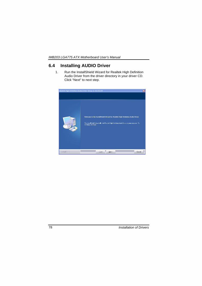
IMB203 LGA775 ATX Motherboard Userrsquos Manual
Installation of Drivers 81
2 An Intelreg license agreement appears that you need to continue the setup program by clicking ldquoYesrdquo to accept the terms
IMB203 LGA775 ATX Motherboard Userrsquos Manual
Installation of Drivers 82
3 Refer to the Readme file below to view the system requirements and installation information Click ldquoNextrdquo to next setup
4 Please wait while running the following installation operation
IMB203 LGA775 ATX Motherboard Userrsquos Manual
Installation of Drivers 83
5 Click ldquoFinishrdquo to complete the installation
IMB203 LGA775 ATX Motherboard Userrsquos Manual
Installation of Drivers 84
652 LMS_SOL_IS Setup
1 Run the setup program to install Intelreg Active Management Technology onto your computer It is strongly recommended that you exit all programs before continuing Click ldquoNextrdquo to next step
IMB203 LGA775 ATX Motherboard Userrsquos Manual
Installation of Drivers 85
2 An Intelreg license agreement appears that you need to continue the setup program by clicking ldquoYesrdquo to accept the terms
IMB203 LGA775 ATX Motherboard Userrsquos Manual
Installation of Drivers 86
3 Refer to the Readme file below to view the system requirements and installation information Click ldquoNextrdquo to next setup
4 Please wait while running the following installation operation
IMB203 LGA775 ATX Motherboard Userrsquos Manual
Installation of Drivers 87
5 Click ldquoFinishrdquo to complete the installation
IMB203 LGA775 ATX Motherboard Userrsquos Manual
Installation of Drivers 88
66 Installing MEI (Management Engine Interface) Driver
Note You must download and properly install the required NET version 35 provided from a separate downloading of the actual FimwareTools kit releases posted on VIP prior to loading the MEILMS Driver stack
1 Run the setup program to install Intelreg Management Engine
Interface onto your computer It is strongly recommended that you exit all programs before continuing Click ldquoNextrdquo to next step
格式化 字型 (符號) Arial
格式化 字型 (符號) Arial 非加寬 緊縮
IMB203 LGA775 ATX Motherboard Userrsquos Manual
Installation of Drivers 89
2 An Intelreg license agreement appears that you need to continue the setup program by clicking ldquoYesrdquo to accept the terms
IMB203 LGA775 ATX Motherboard Userrsquos Manual
Installation of Drivers 90
3 Refer to the Readme file below to view the system requirements and installation information Click ldquoNextrdquo to next setup
4 Please wait while running the following installation operation
IMB203 LGA775 ATX Motherboard Userrsquos Manual
Installation of Drivers 91
5 Click ldquoFinishrdquo to complete the installation
IMB203 LGA775 ATX Motherboard Userrsquos Manual
Installation of Drivers 92
MEMO
IMB203 LGA775 ATX Motherboard Userrsquos Manual
Watchdog Timer 93
APPENDIX A WATCHDOG TIMER
Watchdog Timer Setting After the system stops working for a while it can be auto-reset by the Watchdog Timer The integrated Watchdog Timer can be set up in the system reset mode by program
Using the Watchdog Function Start darr Un-Lock WDT O 2E 87 Un-lock super IO
O 2E 87 Un-lock super IO darr Set WDT Function O 2E 2D O 2F 20 Select Logic device O 2E 07 O 2F 08 darr Activate WDT O 2E 30
O 2F 01 Set Second or Minute O 2E F5
O 2F N N=00 or 08(See below table) darr Set base timer O 2E F6
O 2F M=000102hellipFF(Hex) Value=0 to 255 darr WDT counting
re-set timer O 2E F6
O 2F M M=000102hellipFF(See below table) darr
格式化
格式化 項目符號及編號
格式化 項目符號及編號
格式化 字型 8 點 字型色彩黑色
格式化 字型 8 點 字型色彩黑色
格式化 定位點 1257 字元左 + 不在 1012 字元 + 1386字元
格式化 字型 8 點 字型色彩黑色
格式化 定位點 1257 字元左 + 不在 134 字元 + 1362字元
格式化 字型色彩 黑色
格式化 字型色彩 黑色
刪除
IMB203 LGA775 ATX Motherboard Userrsquos Manual
Watchdog Timer 94
IF No re-set timer WDT time-out generate RESET IF to disable WDT O 2E 30
O 2F 00 Can be disable at any time
N=00
M= 00h Time-out Disable 01h Time-out occurs after 1 second 02h Time-out occurs after 2 second 03h Time-out occurs after 3 second helliphelliphelliphelliphelliphelliphelliphelliphellip FFh Time-out occurs after 255 second
N=08
M= 00h Time-out Disable 01h Time-out occurs after 1 minute 02h Time-out occurs after 2 minutes 03h Time-out occurs after 3 minutes helliphelliphelliphelliphelliphelliphelliphelliphellip
FFh Time-out occurs after 255 minutes
格式化 字型色彩 黑色
格式化 字型色彩 黑色
IMB203 LGA775 ATX Motherboard Userrsquos Manual
PCI IRQ Routing 95
APPENDIX B PCI IRQ ROUTING
PICMG PCI IRQ Routing
Device ID Slot Int
PCI Slot 0 31 0 BCDA PCI Slot 1 30 1 CDAB PCI Slot 2 29 2 DABC PCI Slot 3 28 3 ABCD
IMB203 LGA775 ATX Motherboard Userrsquos Manual
PCI IRQ Routing 96
MEMO
IMB203 LGA775 ATX Motherboard Userrsquos Manual
Configuring SATA for RAID Function 97
APPENDIX C CONFIGURING SATA FOR RAID
FUNCTION
Configuring SATA Hard Drive(s) for RAID Function (Controller IntelregICH10DODO DH only) Please follow up the steps below to configure SATA hard drive(s) (1) Install SATA hard drive(s) in your system (2) Enter the BIOS Setup to configure SATA controller mode and boot
sequence (3) Configure RAID by the RAID BIOS (4) Install the SATA controller driver during the OS installation Before you begin the SATA configuration please prepare (a) Two SATA hard drives (to ensure optimal performance it is
recommended that you use two hard drives with identical model and capacity) If you do not want to create RAID with the SATA controller you may prepare only one hard drive
(b) An empty formatted floppy disk (c) Windows XP setup disk (1) Installing SATA hard drive(s) in your system
Connect one end of the SATA signal cable to the rear of the SATA hard drive and the other end to available SATA port(s) on the board Then connect the power connector of power supply to the hard drive
(2) Configuring SATA controller mode and boot sequence by the BIOS Setup You have to make sure whether the SATA controller is configured correctly by system BIOS Setup and set up BIOS boot sequence for the SATA hard drive(s)
IMB203 LGA775 ATX Motherboard Userrsquos Manual
Configuring SATA for RAID Function 98
(2)-1-1 Turn on your system and then press the Del button to enter BIOS Setup during running POST (Power-On Self Test) If you want to create RAID just go to the Advanced Settings menuIDE configuration select the Configure SATA1 as and press ltEntergt for more options
IMB203 LGA775 ATX Motherboard Userrsquos Manual
Configuring SATA for RAID Function 99
(2)-1-2 A list of options appears please select RAID
IMB203 LGA775 ATX Motherboard Userrsquos Manual
Configuring SATA for RAID Function 100
(2)-2 Set CDROM for First Boot Device under the Boot Settings menu to boot CD-ROM after system restarts
(2)-3 Save and exit the BIOS Setup
IMB203 LGA775 ATX Motherboard Userrsquos Manual
Configuring SATA for RAID Function 101
(3) Configuring RAID by the RAID BIOS Enter the RAID BIOS setup utility to configure a RAID array Skip this step and proceed to Section 4 if you do not want to create a RAID (3)-1 After the POST memory testing and before the operating
system booting a message Press ltCtrl-Igt to enter Configuration Utility shows up accordingly press ltCTRL+ Igt to enter the RAID BIOS setup utility
(3)-2 After you press ltCTRL+ Igt the Create RAID Volume screen will appear If you want to create a RAID array select the Create RAID Volume option in the Main Menu and press ENTER
IMB203 LGA775 ATX Motherboard Userrsquos Manual
Configuring SATA for RAID Function 102
(3)-3-1 After entering the CREATE VOLUME MENU screen you can type the disk array name with 1~16 letters (letters cannot be special characters) in the item ldquoNamerdquo
(3)-3-2 When finished press ENTER to select a RAID level There are three RAID levels RAID0 RAID1 and RAID5 amp RAID10 Select a RAID level and press ENTER
IMB203 LGA775 ATX Motherboard Userrsquos Manual
Configuring SATA for RAID Function 103
(3)-4 Set the stripe block size The KB is the standard unit of stripe block size The stripe block size can be 4KB to 128KB After the setting press ENTER for the array capacity
(3)-5 After setting all the items on the menu select Create Volume
and press ENTER to start creating the RAID array
IMB203 LGA775 ATX Motherboard Userrsquos Manual
Configuring SATA for RAID Function 104
(3)-6 When prompting the confirmation press ldquoYldquo to create this volume or ldquoNldquo to cancel the creation
After the creation is completed you can see detailed information about the RAID Array in the DISKVOLUME INFORMATION section including RAID mode disk block size disk name and disk capacity etc
IMB203 LGA775 ATX Motherboard Userrsquos Manual
Configuring SATA for RAID Function 105
Delete RAID Volume If you want to delete a RAID volume select the Delete RAID Volume option in Main Menu Press ENTER and follow on-screen instructions
Please press [ESC] to exit the RAID BIOS utility Now you can proceed to install a SATA driver controller and the operating system
IMB203 LGA775 ATX Motherboard Userrsquos Manual
Configuring SATA for RAID Function 106
(4) Making a SATA Driver Disk To install the operating system onto a serial ATA hard disk successfully you need to install the SATA controller driver during the OS installation Without the driver the hard disk may not be recognized during the Windows setup process First of all please format a blank floppy disk Secondly follow up these steps below to produce a SATA driver disk Users can insert the Driver CD and the formatted blank floppy disk in another system And then please copy all of file of the f6flpy32 folder in the Driver CD to a floppy disk Note Please copy all of file of the f6flpy64 folder if installing 64-bit
Windows Operating System
IMB203 LGA775 ATX Motherboard Userrsquos Manual
Configuring SATA for RAID Function 107
(5) Installing the SATA controller driver during the OS installation Now the SATA driver disk is ready and BIOS settings configured you can proceed to install Windows 2000XP onto your SATA hard drive using the SATA driver Here is an example for Windows XP installation (5)-1 Restart your system to boot the Windows 2000XP Setup disk
and press F6 button as soon as you see the message Press F6 if you need to install a 3rd party SCSI or RAID driver After pressing the F6 button there will be a few moments for some files being loaded before next screen appears
IMB203 LGA775 ATX Motherboard Userrsquos Manual
Configuring SATA for RAID Function 108
(5)-2 When you see the screen below insert the floppy disk containing the SATA driver and press ldquoSrdquo
(5)-3 If the Setup correctly recognizes the driver of the floppy disk
a controller menu will appear below Use the ARROW keys to select Intel(R) ICH8RICH9RICH10RDO SATA RAID Controller and press ENTER Then it will begin to load the SATA driver from the floppy disk
IMB203 LGA775 ATX Motherboard Userrsquos Manual
Configuring SATA for RAID Function 109
Note If a message on the screen saying that one or some file(s) cannot be found please check the floppy disk or copy the correct SATA driver again from the driver CD
IMB203 LGA775 ATX Motherboard Userrsquos Manual
Configuring SATA for RAID Function 110
MEMO
IMB203 LGA775 ATX Motherboard Userrsquos Manual
iAMT Settings 111
APPENDIX D iAMT SETTINGS
The Intelreg Active Management Technology (Intelreg iAMT) has decreased a major barrier to IT efficiency that uses built-in platform capabilities and popular third-party management and security applications to allow IT a better discovering healing and protection their networked computing assets In order to utilize Intel iAMT you must enter the ME BIOS (CTRL + P during system startup) change the ME BIOS password and then select ldquoIntelreg iAMTrdquo as the manageability feature
D1 Entering MEBx 1 You must go to BIOS TO start iAMT function 2 Exit from BIOS after starting iAMT and press Ctrl+P to enter MEBx Setting
It is better to press Ctrl+P before the screen popping out
格式化
IMB203 LGA775 ATX Motherboard Userrsquos Manual
iAMT Settings 112
D2 Set amp Change Password 1 You will be asked to set a password when first log in The default
password is lsquoadminrsquo
2 You will be asked to change the password before setting ME
Change Password
IMB203 LGA775 ATX Motherboard Userrsquos Manual
iAMT Settings 113
3 You must confirm your new password while revising (as Remark 1)
Remark 1 The new password must contain (example 11qqQQ) (default value)
Eight characters
One upper case
One lower case
One number
One special symbol such as $ or
( excepted)
Underline ( _ ) and space are valid characters for password but they wonrsquot make higher complexity
IMB203 LGA775 ATX Motherboard Userrsquos Manual
iAMT Settings 114
D3 Intelreg iAMT Settings 1 Select Intelreg iAMT Configuration and press ltENTERgt
2 Key in the Host Name If Intelreg iAMT set to lsquoDHCPlsquo the Host name must be identical to the operating system mechanic
IMB203 LGA775 ATX Motherboard Userrsquos Manual
iAMT Settings 115
3 Select TCPIP to get into Network interface and set it to lsquoENABLEDrsquo into DHCP Mode and set it to lsquoDISABLEDrsquo (as Remark 2) into Domain name and set the Intel Management Engine domain name such as lsquoAMTintelcomrsquo
(3-1)
(3-2)
IMB203 LGA775 ATX Motherboard Userrsquos Manual
iAMT Settings 116
Remark 2 DHCP Mode lsquoDISABLEDlsquo if DHCP Mode is disabled you can make the following settings
IP address
Subnet mask
IMB203 LGA775 ATX Motherboard Userrsquos Manual
iAMT Settings 117
Default Gateway address
Preferred DNS address
IMB203 LGA775 ATX Motherboard Userrsquos Manual
iAMT Settings 118
Alternate DNS address
Domain name
4 Exit from MEBx after completing the iAMT settings
IMB203 LGA775 ATX Motherboard Userrsquos Manual
iAMT Settings 119
D4 iAMT Web Console 1 From a web browser please type http(IP ADDRESS)16992
which connects to iAMT Web Example http1014021416992
2 To log on you will be required to type in username and password
for access to the Web
USER admin (default value)
PASS (MEBx password)
IMB203 LGA775 ATX Motherboard Userrsquos Manual
iAMT Settings 120
3 Enter the iAMT Web
4 Click Remote Control and select commands on the right side
IMB203 LGA775 ATX Motherboard Userrsquos Manual
iAMT Settings 121
5 When you have finished using the iAMT Web console close the Web browser
IMB203 LGA775 ATX Motherboard Userrsquos Manual
iAMT Settings 122
MEMO
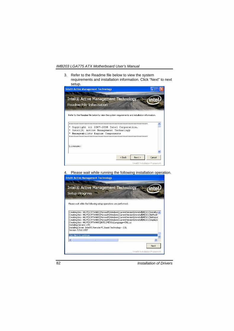
IMB203 LGA775 ATX Motherboard Userrsquos Manual
Installation of Drivers 82
3 Refer to the Readme file below to view the system requirements and installation information Click ldquoNextrdquo to next setup
4 Please wait while running the following installation operation
IMB203 LGA775 ATX Motherboard Userrsquos Manual
Installation of Drivers 83
5 Click ldquoFinishrdquo to complete the installation
IMB203 LGA775 ATX Motherboard Userrsquos Manual
Installation of Drivers 84
652 LMS_SOL_IS Setup
1 Run the setup program to install Intelreg Active Management Technology onto your computer It is strongly recommended that you exit all programs before continuing Click ldquoNextrdquo to next step
IMB203 LGA775 ATX Motherboard Userrsquos Manual
Installation of Drivers 85
2 An Intelreg license agreement appears that you need to continue the setup program by clicking ldquoYesrdquo to accept the terms
IMB203 LGA775 ATX Motherboard Userrsquos Manual
Installation of Drivers 86
3 Refer to the Readme file below to view the system requirements and installation information Click ldquoNextrdquo to next setup
4 Please wait while running the following installation operation
IMB203 LGA775 ATX Motherboard Userrsquos Manual
Installation of Drivers 87
5 Click ldquoFinishrdquo to complete the installation
IMB203 LGA775 ATX Motherboard Userrsquos Manual
Installation of Drivers 88
66 Installing MEI (Management Engine Interface) Driver
Note You must download and properly install the required NET version 35 provided from a separate downloading of the actual FimwareTools kit releases posted on VIP prior to loading the MEILMS Driver stack
1 Run the setup program to install Intelreg Management Engine
Interface onto your computer It is strongly recommended that you exit all programs before continuing Click ldquoNextrdquo to next step
格式化 字型 (符號) Arial
格式化 字型 (符號) Arial 非加寬 緊縮
IMB203 LGA775 ATX Motherboard Userrsquos Manual
Installation of Drivers 89
2 An Intelreg license agreement appears that you need to continue the setup program by clicking ldquoYesrdquo to accept the terms
IMB203 LGA775 ATX Motherboard Userrsquos Manual
Installation of Drivers 90
3 Refer to the Readme file below to view the system requirements and installation information Click ldquoNextrdquo to next setup
4 Please wait while running the following installation operation
IMB203 LGA775 ATX Motherboard Userrsquos Manual
Installation of Drivers 91
5 Click ldquoFinishrdquo to complete the installation
IMB203 LGA775 ATX Motherboard Userrsquos Manual
Installation of Drivers 92
MEMO
IMB203 LGA775 ATX Motherboard Userrsquos Manual
Watchdog Timer 93
APPENDIX A WATCHDOG TIMER
Watchdog Timer Setting After the system stops working for a while it can be auto-reset by the Watchdog Timer The integrated Watchdog Timer can be set up in the system reset mode by program
Using the Watchdog Function Start darr Un-Lock WDT O 2E 87 Un-lock super IO
O 2E 87 Un-lock super IO darr Set WDT Function O 2E 2D O 2F 20 Select Logic device O 2E 07 O 2F 08 darr Activate WDT O 2E 30
O 2F 01 Set Second or Minute O 2E F5
O 2F N N=00 or 08(See below table) darr Set base timer O 2E F6
O 2F M=000102hellipFF(Hex) Value=0 to 255 darr WDT counting
re-set timer O 2E F6
O 2F M M=000102hellipFF(See below table) darr
格式化
格式化 項目符號及編號
格式化 項目符號及編號
格式化 字型 8 點 字型色彩黑色
格式化 字型 8 點 字型色彩黑色
格式化 定位點 1257 字元左 + 不在 1012 字元 + 1386字元
格式化 字型 8 點 字型色彩黑色
格式化 定位點 1257 字元左 + 不在 134 字元 + 1362字元
格式化 字型色彩 黑色
格式化 字型色彩 黑色
刪除
IMB203 LGA775 ATX Motherboard Userrsquos Manual
Watchdog Timer 94
IF No re-set timer WDT time-out generate RESET IF to disable WDT O 2E 30
O 2F 00 Can be disable at any time
N=00
M= 00h Time-out Disable 01h Time-out occurs after 1 second 02h Time-out occurs after 2 second 03h Time-out occurs after 3 second helliphelliphelliphelliphelliphelliphelliphelliphellip FFh Time-out occurs after 255 second
N=08
M= 00h Time-out Disable 01h Time-out occurs after 1 minute 02h Time-out occurs after 2 minutes 03h Time-out occurs after 3 minutes helliphelliphelliphelliphelliphelliphelliphelliphellip
FFh Time-out occurs after 255 minutes
格式化 字型色彩 黑色
格式化 字型色彩 黑色
IMB203 LGA775 ATX Motherboard Userrsquos Manual
PCI IRQ Routing 95
APPENDIX B PCI IRQ ROUTING
PICMG PCI IRQ Routing
Device ID Slot Int
PCI Slot 0 31 0 BCDA PCI Slot 1 30 1 CDAB PCI Slot 2 29 2 DABC PCI Slot 3 28 3 ABCD
IMB203 LGA775 ATX Motherboard Userrsquos Manual
PCI IRQ Routing 96
MEMO
IMB203 LGA775 ATX Motherboard Userrsquos Manual
Configuring SATA for RAID Function 97
APPENDIX C CONFIGURING SATA FOR RAID
FUNCTION
Configuring SATA Hard Drive(s) for RAID Function (Controller IntelregICH10DODO DH only) Please follow up the steps below to configure SATA hard drive(s) (1) Install SATA hard drive(s) in your system (2) Enter the BIOS Setup to configure SATA controller mode and boot
sequence (3) Configure RAID by the RAID BIOS (4) Install the SATA controller driver during the OS installation Before you begin the SATA configuration please prepare (a) Two SATA hard drives (to ensure optimal performance it is
recommended that you use two hard drives with identical model and capacity) If you do not want to create RAID with the SATA controller you may prepare only one hard drive
(b) An empty formatted floppy disk (c) Windows XP setup disk (1) Installing SATA hard drive(s) in your system
Connect one end of the SATA signal cable to the rear of the SATA hard drive and the other end to available SATA port(s) on the board Then connect the power connector of power supply to the hard drive
(2) Configuring SATA controller mode and boot sequence by the BIOS Setup You have to make sure whether the SATA controller is configured correctly by system BIOS Setup and set up BIOS boot sequence for the SATA hard drive(s)
IMB203 LGA775 ATX Motherboard Userrsquos Manual
Configuring SATA for RAID Function 98
(2)-1-1 Turn on your system and then press the Del button to enter BIOS Setup during running POST (Power-On Self Test) If you want to create RAID just go to the Advanced Settings menuIDE configuration select the Configure SATA1 as and press ltEntergt for more options
IMB203 LGA775 ATX Motherboard Userrsquos Manual
Configuring SATA for RAID Function 99
(2)-1-2 A list of options appears please select RAID
IMB203 LGA775 ATX Motherboard Userrsquos Manual
Configuring SATA for RAID Function 100
(2)-2 Set CDROM for First Boot Device under the Boot Settings menu to boot CD-ROM after system restarts
(2)-3 Save and exit the BIOS Setup
IMB203 LGA775 ATX Motherboard Userrsquos Manual
Configuring SATA for RAID Function 101
(3) Configuring RAID by the RAID BIOS Enter the RAID BIOS setup utility to configure a RAID array Skip this step and proceed to Section 4 if you do not want to create a RAID (3)-1 After the POST memory testing and before the operating
system booting a message Press ltCtrl-Igt to enter Configuration Utility shows up accordingly press ltCTRL+ Igt to enter the RAID BIOS setup utility
(3)-2 After you press ltCTRL+ Igt the Create RAID Volume screen will appear If you want to create a RAID array select the Create RAID Volume option in the Main Menu and press ENTER
IMB203 LGA775 ATX Motherboard Userrsquos Manual
Configuring SATA for RAID Function 102
(3)-3-1 After entering the CREATE VOLUME MENU screen you can type the disk array name with 1~16 letters (letters cannot be special characters) in the item ldquoNamerdquo
(3)-3-2 When finished press ENTER to select a RAID level There are three RAID levels RAID0 RAID1 and RAID5 amp RAID10 Select a RAID level and press ENTER
IMB203 LGA775 ATX Motherboard Userrsquos Manual
Configuring SATA for RAID Function 103
(3)-4 Set the stripe block size The KB is the standard unit of stripe block size The stripe block size can be 4KB to 128KB After the setting press ENTER for the array capacity
(3)-5 After setting all the items on the menu select Create Volume
and press ENTER to start creating the RAID array
IMB203 LGA775 ATX Motherboard Userrsquos Manual
Configuring SATA for RAID Function 104
(3)-6 When prompting the confirmation press ldquoYldquo to create this volume or ldquoNldquo to cancel the creation
After the creation is completed you can see detailed information about the RAID Array in the DISKVOLUME INFORMATION section including RAID mode disk block size disk name and disk capacity etc
IMB203 LGA775 ATX Motherboard Userrsquos Manual
Configuring SATA for RAID Function 105
Delete RAID Volume If you want to delete a RAID volume select the Delete RAID Volume option in Main Menu Press ENTER and follow on-screen instructions
Please press [ESC] to exit the RAID BIOS utility Now you can proceed to install a SATA driver controller and the operating system
IMB203 LGA775 ATX Motherboard Userrsquos Manual
Configuring SATA for RAID Function 106
(4) Making a SATA Driver Disk To install the operating system onto a serial ATA hard disk successfully you need to install the SATA controller driver during the OS installation Without the driver the hard disk may not be recognized during the Windows setup process First of all please format a blank floppy disk Secondly follow up these steps below to produce a SATA driver disk Users can insert the Driver CD and the formatted blank floppy disk in another system And then please copy all of file of the f6flpy32 folder in the Driver CD to a floppy disk Note Please copy all of file of the f6flpy64 folder if installing 64-bit
Windows Operating System
IMB203 LGA775 ATX Motherboard Userrsquos Manual
Configuring SATA for RAID Function 107
(5) Installing the SATA controller driver during the OS installation Now the SATA driver disk is ready and BIOS settings configured you can proceed to install Windows 2000XP onto your SATA hard drive using the SATA driver Here is an example for Windows XP installation (5)-1 Restart your system to boot the Windows 2000XP Setup disk
and press F6 button as soon as you see the message Press F6 if you need to install a 3rd party SCSI or RAID driver After pressing the F6 button there will be a few moments for some files being loaded before next screen appears
IMB203 LGA775 ATX Motherboard Userrsquos Manual
Configuring SATA for RAID Function 108
(5)-2 When you see the screen below insert the floppy disk containing the SATA driver and press ldquoSrdquo
(5)-3 If the Setup correctly recognizes the driver of the floppy disk
a controller menu will appear below Use the ARROW keys to select Intel(R) ICH8RICH9RICH10RDO SATA RAID Controller and press ENTER Then it will begin to load the SATA driver from the floppy disk
IMB203 LGA775 ATX Motherboard Userrsquos Manual
Configuring SATA for RAID Function 109
Note If a message on the screen saying that one or some file(s) cannot be found please check the floppy disk or copy the correct SATA driver again from the driver CD
IMB203 LGA775 ATX Motherboard Userrsquos Manual
Configuring SATA for RAID Function 110
MEMO
IMB203 LGA775 ATX Motherboard Userrsquos Manual
iAMT Settings 111
APPENDIX D iAMT SETTINGS
The Intelreg Active Management Technology (Intelreg iAMT) has decreased a major barrier to IT efficiency that uses built-in platform capabilities and popular third-party management and security applications to allow IT a better discovering healing and protection their networked computing assets In order to utilize Intel iAMT you must enter the ME BIOS (CTRL + P during system startup) change the ME BIOS password and then select ldquoIntelreg iAMTrdquo as the manageability feature
D1 Entering MEBx 1 You must go to BIOS TO start iAMT function 2 Exit from BIOS after starting iAMT and press Ctrl+P to enter MEBx Setting
It is better to press Ctrl+P before the screen popping out
格式化
IMB203 LGA775 ATX Motherboard Userrsquos Manual
iAMT Settings 112
D2 Set amp Change Password 1 You will be asked to set a password when first log in The default
password is lsquoadminrsquo
2 You will be asked to change the password before setting ME
Change Password
IMB203 LGA775 ATX Motherboard Userrsquos Manual
iAMT Settings 113
3 You must confirm your new password while revising (as Remark 1)
Remark 1 The new password must contain (example 11qqQQ) (default value)
Eight characters
One upper case
One lower case
One number
One special symbol such as $ or
( excepted)
Underline ( _ ) and space are valid characters for password but they wonrsquot make higher complexity
IMB203 LGA775 ATX Motherboard Userrsquos Manual
iAMT Settings 114
D3 Intelreg iAMT Settings 1 Select Intelreg iAMT Configuration and press ltENTERgt
2 Key in the Host Name If Intelreg iAMT set to lsquoDHCPlsquo the Host name must be identical to the operating system mechanic
IMB203 LGA775 ATX Motherboard Userrsquos Manual
iAMT Settings 115
3 Select TCPIP to get into Network interface and set it to lsquoENABLEDrsquo into DHCP Mode and set it to lsquoDISABLEDrsquo (as Remark 2) into Domain name and set the Intel Management Engine domain name such as lsquoAMTintelcomrsquo
(3-1)
(3-2)
IMB203 LGA775 ATX Motherboard Userrsquos Manual
iAMT Settings 116
Remark 2 DHCP Mode lsquoDISABLEDlsquo if DHCP Mode is disabled you can make the following settings
IP address
Subnet mask
IMB203 LGA775 ATX Motherboard Userrsquos Manual
iAMT Settings 117
Default Gateway address
Preferred DNS address
IMB203 LGA775 ATX Motherboard Userrsquos Manual
iAMT Settings 118
Alternate DNS address
Domain name
4 Exit from MEBx after completing the iAMT settings
IMB203 LGA775 ATX Motherboard Userrsquos Manual
iAMT Settings 119
D4 iAMT Web Console 1 From a web browser please type http(IP ADDRESS)16992
which connects to iAMT Web Example http1014021416992
2 To log on you will be required to type in username and password
for access to the Web
USER admin (default value)
PASS (MEBx password)
IMB203 LGA775 ATX Motherboard Userrsquos Manual
iAMT Settings 120
3 Enter the iAMT Web
4 Click Remote Control and select commands on the right side
IMB203 LGA775 ATX Motherboard Userrsquos Manual
iAMT Settings 121
5 When you have finished using the iAMT Web console close the Web browser
IMB203 LGA775 ATX Motherboard Userrsquos Manual
iAMT Settings 122
MEMO
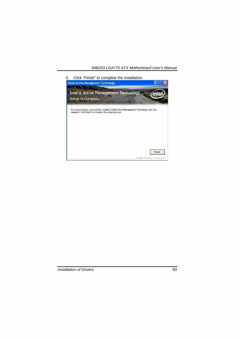
IMB203 LGA775 ATX Motherboard Userrsquos Manual
Installation of Drivers 83
5 Click ldquoFinishrdquo to complete the installation
IMB203 LGA775 ATX Motherboard Userrsquos Manual
Installation of Drivers 84
652 LMS_SOL_IS Setup
1 Run the setup program to install Intelreg Active Management Technology onto your computer It is strongly recommended that you exit all programs before continuing Click ldquoNextrdquo to next step
IMB203 LGA775 ATX Motherboard Userrsquos Manual
Installation of Drivers 85
2 An Intelreg license agreement appears that you need to continue the setup program by clicking ldquoYesrdquo to accept the terms
IMB203 LGA775 ATX Motherboard Userrsquos Manual
Installation of Drivers 86
3 Refer to the Readme file below to view the system requirements and installation information Click ldquoNextrdquo to next setup
4 Please wait while running the following installation operation
IMB203 LGA775 ATX Motherboard Userrsquos Manual
Installation of Drivers 87
5 Click ldquoFinishrdquo to complete the installation
IMB203 LGA775 ATX Motherboard Userrsquos Manual
Installation of Drivers 88
66 Installing MEI (Management Engine Interface) Driver
Note You must download and properly install the required NET version 35 provided from a separate downloading of the actual FimwareTools kit releases posted on VIP prior to loading the MEILMS Driver stack
1 Run the setup program to install Intelreg Management Engine
Interface onto your computer It is strongly recommended that you exit all programs before continuing Click ldquoNextrdquo to next step
格式化 字型 (符號) Arial
格式化 字型 (符號) Arial 非加寬 緊縮
IMB203 LGA775 ATX Motherboard Userrsquos Manual
Installation of Drivers 89
2 An Intelreg license agreement appears that you need to continue the setup program by clicking ldquoYesrdquo to accept the terms
IMB203 LGA775 ATX Motherboard Userrsquos Manual
Installation of Drivers 90
3 Refer to the Readme file below to view the system requirements and installation information Click ldquoNextrdquo to next setup
4 Please wait while running the following installation operation
IMB203 LGA775 ATX Motherboard Userrsquos Manual
Installation of Drivers 91
5 Click ldquoFinishrdquo to complete the installation
IMB203 LGA775 ATX Motherboard Userrsquos Manual
Installation of Drivers 92
MEMO
IMB203 LGA775 ATX Motherboard Userrsquos Manual
Watchdog Timer 93
APPENDIX A WATCHDOG TIMER
Watchdog Timer Setting After the system stops working for a while it can be auto-reset by the Watchdog Timer The integrated Watchdog Timer can be set up in the system reset mode by program
Using the Watchdog Function Start darr Un-Lock WDT O 2E 87 Un-lock super IO
O 2E 87 Un-lock super IO darr Set WDT Function O 2E 2D O 2F 20 Select Logic device O 2E 07 O 2F 08 darr Activate WDT O 2E 30
O 2F 01 Set Second or Minute O 2E F5
O 2F N N=00 or 08(See below table) darr Set base timer O 2E F6
O 2F M=000102hellipFF(Hex) Value=0 to 255 darr WDT counting
re-set timer O 2E F6
O 2F M M=000102hellipFF(See below table) darr
格式化
格式化 項目符號及編號
格式化 項目符號及編號
格式化 字型 8 點 字型色彩黑色
格式化 字型 8 點 字型色彩黑色
格式化 定位點 1257 字元左 + 不在 1012 字元 + 1386字元
格式化 字型 8 點 字型色彩黑色
格式化 定位點 1257 字元左 + 不在 134 字元 + 1362字元
格式化 字型色彩 黑色
格式化 字型色彩 黑色
刪除
IMB203 LGA775 ATX Motherboard Userrsquos Manual
Watchdog Timer 94
IF No re-set timer WDT time-out generate RESET IF to disable WDT O 2E 30
O 2F 00 Can be disable at any time
N=00
M= 00h Time-out Disable 01h Time-out occurs after 1 second 02h Time-out occurs after 2 second 03h Time-out occurs after 3 second helliphelliphelliphelliphelliphelliphelliphelliphellip FFh Time-out occurs after 255 second
N=08
M= 00h Time-out Disable 01h Time-out occurs after 1 minute 02h Time-out occurs after 2 minutes 03h Time-out occurs after 3 minutes helliphelliphelliphelliphelliphelliphelliphelliphellip
FFh Time-out occurs after 255 minutes
格式化 字型色彩 黑色
格式化 字型色彩 黑色
IMB203 LGA775 ATX Motherboard Userrsquos Manual
PCI IRQ Routing 95
APPENDIX B PCI IRQ ROUTING
PICMG PCI IRQ Routing
Device ID Slot Int
PCI Slot 0 31 0 BCDA PCI Slot 1 30 1 CDAB PCI Slot 2 29 2 DABC PCI Slot 3 28 3 ABCD
IMB203 LGA775 ATX Motherboard Userrsquos Manual
PCI IRQ Routing 96
MEMO
IMB203 LGA775 ATX Motherboard Userrsquos Manual
Configuring SATA for RAID Function 97
APPENDIX C CONFIGURING SATA FOR RAID
FUNCTION
Configuring SATA Hard Drive(s) for RAID Function (Controller IntelregICH10DODO DH only) Please follow up the steps below to configure SATA hard drive(s) (1) Install SATA hard drive(s) in your system (2) Enter the BIOS Setup to configure SATA controller mode and boot
sequence (3) Configure RAID by the RAID BIOS (4) Install the SATA controller driver during the OS installation Before you begin the SATA configuration please prepare (a) Two SATA hard drives (to ensure optimal performance it is
recommended that you use two hard drives with identical model and capacity) If you do not want to create RAID with the SATA controller you may prepare only one hard drive
(b) An empty formatted floppy disk (c) Windows XP setup disk (1) Installing SATA hard drive(s) in your system
Connect one end of the SATA signal cable to the rear of the SATA hard drive and the other end to available SATA port(s) on the board Then connect the power connector of power supply to the hard drive
(2) Configuring SATA controller mode and boot sequence by the BIOS Setup You have to make sure whether the SATA controller is configured correctly by system BIOS Setup and set up BIOS boot sequence for the SATA hard drive(s)
IMB203 LGA775 ATX Motherboard Userrsquos Manual
Configuring SATA for RAID Function 98
(2)-1-1 Turn on your system and then press the Del button to enter BIOS Setup during running POST (Power-On Self Test) If you want to create RAID just go to the Advanced Settings menuIDE configuration select the Configure SATA1 as and press ltEntergt for more options
IMB203 LGA775 ATX Motherboard Userrsquos Manual
Configuring SATA for RAID Function 99
(2)-1-2 A list of options appears please select RAID
IMB203 LGA775 ATX Motherboard Userrsquos Manual
Configuring SATA for RAID Function 100
(2)-2 Set CDROM for First Boot Device under the Boot Settings menu to boot CD-ROM after system restarts
(2)-3 Save and exit the BIOS Setup
IMB203 LGA775 ATX Motherboard Userrsquos Manual
Configuring SATA for RAID Function 101
(3) Configuring RAID by the RAID BIOS Enter the RAID BIOS setup utility to configure a RAID array Skip this step and proceed to Section 4 if you do not want to create a RAID (3)-1 After the POST memory testing and before the operating
system booting a message Press ltCtrl-Igt to enter Configuration Utility shows up accordingly press ltCTRL+ Igt to enter the RAID BIOS setup utility
(3)-2 After you press ltCTRL+ Igt the Create RAID Volume screen will appear If you want to create a RAID array select the Create RAID Volume option in the Main Menu and press ENTER
IMB203 LGA775 ATX Motherboard Userrsquos Manual
Configuring SATA for RAID Function 102
(3)-3-1 After entering the CREATE VOLUME MENU screen you can type the disk array name with 1~16 letters (letters cannot be special characters) in the item ldquoNamerdquo
(3)-3-2 When finished press ENTER to select a RAID level There are three RAID levels RAID0 RAID1 and RAID5 amp RAID10 Select a RAID level and press ENTER
IMB203 LGA775 ATX Motherboard Userrsquos Manual
Configuring SATA for RAID Function 103
(3)-4 Set the stripe block size The KB is the standard unit of stripe block size The stripe block size can be 4KB to 128KB After the setting press ENTER for the array capacity
(3)-5 After setting all the items on the menu select Create Volume
and press ENTER to start creating the RAID array
IMB203 LGA775 ATX Motherboard Userrsquos Manual
Configuring SATA for RAID Function 104
(3)-6 When prompting the confirmation press ldquoYldquo to create this volume or ldquoNldquo to cancel the creation
After the creation is completed you can see detailed information about the RAID Array in the DISKVOLUME INFORMATION section including RAID mode disk block size disk name and disk capacity etc
IMB203 LGA775 ATX Motherboard Userrsquos Manual
Configuring SATA for RAID Function 105
Delete RAID Volume If you want to delete a RAID volume select the Delete RAID Volume option in Main Menu Press ENTER and follow on-screen instructions
Please press [ESC] to exit the RAID BIOS utility Now you can proceed to install a SATA driver controller and the operating system
IMB203 LGA775 ATX Motherboard Userrsquos Manual
Configuring SATA for RAID Function 106
(4) Making a SATA Driver Disk To install the operating system onto a serial ATA hard disk successfully you need to install the SATA controller driver during the OS installation Without the driver the hard disk may not be recognized during the Windows setup process First of all please format a blank floppy disk Secondly follow up these steps below to produce a SATA driver disk Users can insert the Driver CD and the formatted blank floppy disk in another system And then please copy all of file of the f6flpy32 folder in the Driver CD to a floppy disk Note Please copy all of file of the f6flpy64 folder if installing 64-bit
Windows Operating System
IMB203 LGA775 ATX Motherboard Userrsquos Manual
Configuring SATA for RAID Function 107
(5) Installing the SATA controller driver during the OS installation Now the SATA driver disk is ready and BIOS settings configured you can proceed to install Windows 2000XP onto your SATA hard drive using the SATA driver Here is an example for Windows XP installation (5)-1 Restart your system to boot the Windows 2000XP Setup disk
and press F6 button as soon as you see the message Press F6 if you need to install a 3rd party SCSI or RAID driver After pressing the F6 button there will be a few moments for some files being loaded before next screen appears
IMB203 LGA775 ATX Motherboard Userrsquos Manual
Configuring SATA for RAID Function 108
(5)-2 When you see the screen below insert the floppy disk containing the SATA driver and press ldquoSrdquo
(5)-3 If the Setup correctly recognizes the driver of the floppy disk
a controller menu will appear below Use the ARROW keys to select Intel(R) ICH8RICH9RICH10RDO SATA RAID Controller and press ENTER Then it will begin to load the SATA driver from the floppy disk
IMB203 LGA775 ATX Motherboard Userrsquos Manual
Configuring SATA for RAID Function 109
Note If a message on the screen saying that one or some file(s) cannot be found please check the floppy disk or copy the correct SATA driver again from the driver CD
IMB203 LGA775 ATX Motherboard Userrsquos Manual
Configuring SATA for RAID Function 110
MEMO
IMB203 LGA775 ATX Motherboard Userrsquos Manual
iAMT Settings 111
APPENDIX D iAMT SETTINGS
The Intelreg Active Management Technology (Intelreg iAMT) has decreased a major barrier to IT efficiency that uses built-in platform capabilities and popular third-party management and security applications to allow IT a better discovering healing and protection their networked computing assets In order to utilize Intel iAMT you must enter the ME BIOS (CTRL + P during system startup) change the ME BIOS password and then select ldquoIntelreg iAMTrdquo as the manageability feature
D1 Entering MEBx 1 You must go to BIOS TO start iAMT function 2 Exit from BIOS after starting iAMT and press Ctrl+P to enter MEBx Setting
It is better to press Ctrl+P before the screen popping out
格式化
IMB203 LGA775 ATX Motherboard Userrsquos Manual
iAMT Settings 112
D2 Set amp Change Password 1 You will be asked to set a password when first log in The default
password is lsquoadminrsquo
2 You will be asked to change the password before setting ME
Change Password
IMB203 LGA775 ATX Motherboard Userrsquos Manual
iAMT Settings 113
3 You must confirm your new password while revising (as Remark 1)
Remark 1 The new password must contain (example 11qqQQ) (default value)
Eight characters
One upper case
One lower case
One number
One special symbol such as $ or
( excepted)
Underline ( _ ) and space are valid characters for password but they wonrsquot make higher complexity
IMB203 LGA775 ATX Motherboard Userrsquos Manual
iAMT Settings 114
D3 Intelreg iAMT Settings 1 Select Intelreg iAMT Configuration and press ltENTERgt
2 Key in the Host Name If Intelreg iAMT set to lsquoDHCPlsquo the Host name must be identical to the operating system mechanic
IMB203 LGA775 ATX Motherboard Userrsquos Manual
iAMT Settings 115
3 Select TCPIP to get into Network interface and set it to lsquoENABLEDrsquo into DHCP Mode and set it to lsquoDISABLEDrsquo (as Remark 2) into Domain name and set the Intel Management Engine domain name such as lsquoAMTintelcomrsquo
(3-1)
(3-2)
IMB203 LGA775 ATX Motherboard Userrsquos Manual
iAMT Settings 116
Remark 2 DHCP Mode lsquoDISABLEDlsquo if DHCP Mode is disabled you can make the following settings
IP address
Subnet mask
IMB203 LGA775 ATX Motherboard Userrsquos Manual
iAMT Settings 117
Default Gateway address
Preferred DNS address
IMB203 LGA775 ATX Motherboard Userrsquos Manual
iAMT Settings 118
Alternate DNS address
Domain name
4 Exit from MEBx after completing the iAMT settings
IMB203 LGA775 ATX Motherboard Userrsquos Manual
iAMT Settings 119
D4 iAMT Web Console 1 From a web browser please type http(IP ADDRESS)16992
which connects to iAMT Web Example http1014021416992
2 To log on you will be required to type in username and password
for access to the Web
USER admin (default value)
PASS (MEBx password)
IMB203 LGA775 ATX Motherboard Userrsquos Manual
iAMT Settings 120
3 Enter the iAMT Web
4 Click Remote Control and select commands on the right side
IMB203 LGA775 ATX Motherboard Userrsquos Manual
iAMT Settings 121
5 When you have finished using the iAMT Web console close the Web browser
IMB203 LGA775 ATX Motherboard Userrsquos Manual
iAMT Settings 122
MEMO
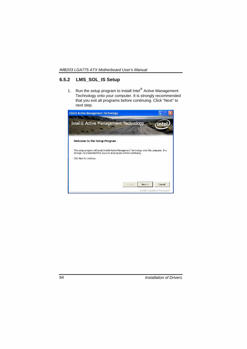
IMB203 LGA775 ATX Motherboard Userrsquos Manual
Installation of Drivers 85
2 An Intelreg license agreement appears that you need to continue the setup program by clicking ldquoYesrdquo to accept the terms
IMB203 LGA775 ATX Motherboard Userrsquos Manual
Installation of Drivers 86
3 Refer to the Readme file below to view the system requirements and installation information Click ldquoNextrdquo to next setup
4 Please wait while running the following installation operation
IMB203 LGA775 ATX Motherboard Userrsquos Manual
Installation of Drivers 87
5 Click ldquoFinishrdquo to complete the installation
IMB203 LGA775 ATX Motherboard Userrsquos Manual
Installation of Drivers 88
66 Installing MEI (Management Engine Interface) Driver
Note You must download and properly install the required NET version 35 provided from a separate downloading of the actual FimwareTools kit releases posted on VIP prior to loading the MEILMS Driver stack
1 Run the setup program to install Intelreg Management Engine
Interface onto your computer It is strongly recommended that you exit all programs before continuing Click ldquoNextrdquo to next step
格式化 字型 (符號) Arial
格式化 字型 (符號) Arial 非加寬 緊縮
IMB203 LGA775 ATX Motherboard Userrsquos Manual
Installation of Drivers 89
2 An Intelreg license agreement appears that you need to continue the setup program by clicking ldquoYesrdquo to accept the terms
IMB203 LGA775 ATX Motherboard Userrsquos Manual
Installation of Drivers 90
3 Refer to the Readme file below to view the system requirements and installation information Click ldquoNextrdquo to next setup
4 Please wait while running the following installation operation
IMB203 LGA775 ATX Motherboard Userrsquos Manual
Installation of Drivers 91
5 Click ldquoFinishrdquo to complete the installation
IMB203 LGA775 ATX Motherboard Userrsquos Manual
Installation of Drivers 92
MEMO
IMB203 LGA775 ATX Motherboard Userrsquos Manual
Watchdog Timer 93
APPENDIX A WATCHDOG TIMER
Watchdog Timer Setting After the system stops working for a while it can be auto-reset by the Watchdog Timer The integrated Watchdog Timer can be set up in the system reset mode by program
Using the Watchdog Function Start darr Un-Lock WDT O 2E 87 Un-lock super IO
O 2E 87 Un-lock super IO darr Set WDT Function O 2E 2D O 2F 20 Select Logic device O 2E 07 O 2F 08 darr Activate WDT O 2E 30
O 2F 01 Set Second or Minute O 2E F5
O 2F N N=00 or 08(See below table) darr Set base timer O 2E F6
O 2F M=000102hellipFF(Hex) Value=0 to 255 darr WDT counting
re-set timer O 2E F6
O 2F M M=000102hellipFF(See below table) darr
格式化
格式化 項目符號及編號
格式化 項目符號及編號
格式化 字型 8 點 字型色彩黑色
格式化 字型 8 點 字型色彩黑色
格式化 定位點 1257 字元左 + 不在 1012 字元 + 1386字元
格式化 字型 8 點 字型色彩黑色
格式化 定位點 1257 字元左 + 不在 134 字元 + 1362字元
格式化 字型色彩 黑色
格式化 字型色彩 黑色
刪除
IMB203 LGA775 ATX Motherboard Userrsquos Manual
Watchdog Timer 94
IF No re-set timer WDT time-out generate RESET IF to disable WDT O 2E 30
O 2F 00 Can be disable at any time
N=00
M= 00h Time-out Disable 01h Time-out occurs after 1 second 02h Time-out occurs after 2 second 03h Time-out occurs after 3 second helliphelliphelliphelliphelliphelliphelliphelliphellip FFh Time-out occurs after 255 second
N=08
M= 00h Time-out Disable 01h Time-out occurs after 1 minute 02h Time-out occurs after 2 minutes 03h Time-out occurs after 3 minutes helliphelliphelliphelliphelliphelliphelliphelliphellip
FFh Time-out occurs after 255 minutes
格式化 字型色彩 黑色
格式化 字型色彩 黑色
IMB203 LGA775 ATX Motherboard Userrsquos Manual
PCI IRQ Routing 95
APPENDIX B PCI IRQ ROUTING
PICMG PCI IRQ Routing
Device ID Slot Int
PCI Slot 0 31 0 BCDA PCI Slot 1 30 1 CDAB PCI Slot 2 29 2 DABC PCI Slot 3 28 3 ABCD
IMB203 LGA775 ATX Motherboard Userrsquos Manual
PCI IRQ Routing 96
MEMO
IMB203 LGA775 ATX Motherboard Userrsquos Manual
Configuring SATA for RAID Function 97
APPENDIX C CONFIGURING SATA FOR RAID
FUNCTION
Configuring SATA Hard Drive(s) for RAID Function (Controller IntelregICH10DODO DH only) Please follow up the steps below to configure SATA hard drive(s) (1) Install SATA hard drive(s) in your system (2) Enter the BIOS Setup to configure SATA controller mode and boot
sequence (3) Configure RAID by the RAID BIOS (4) Install the SATA controller driver during the OS installation Before you begin the SATA configuration please prepare (a) Two SATA hard drives (to ensure optimal performance it is
recommended that you use two hard drives with identical model and capacity) If you do not want to create RAID with the SATA controller you may prepare only one hard drive
(b) An empty formatted floppy disk (c) Windows XP setup disk (1) Installing SATA hard drive(s) in your system
Connect one end of the SATA signal cable to the rear of the SATA hard drive and the other end to available SATA port(s) on the board Then connect the power connector of power supply to the hard drive
(2) Configuring SATA controller mode and boot sequence by the BIOS Setup You have to make sure whether the SATA controller is configured correctly by system BIOS Setup and set up BIOS boot sequence for the SATA hard drive(s)
IMB203 LGA775 ATX Motherboard Userrsquos Manual
Configuring SATA for RAID Function 98
(2)-1-1 Turn on your system and then press the Del button to enter BIOS Setup during running POST (Power-On Self Test) If you want to create RAID just go to the Advanced Settings menuIDE configuration select the Configure SATA1 as and press ltEntergt for more options
IMB203 LGA775 ATX Motherboard Userrsquos Manual
Configuring SATA for RAID Function 99
(2)-1-2 A list of options appears please select RAID
IMB203 LGA775 ATX Motherboard Userrsquos Manual
Configuring SATA for RAID Function 100
(2)-2 Set CDROM for First Boot Device under the Boot Settings menu to boot CD-ROM after system restarts
(2)-3 Save and exit the BIOS Setup
IMB203 LGA775 ATX Motherboard Userrsquos Manual
Configuring SATA for RAID Function 101
(3) Configuring RAID by the RAID BIOS Enter the RAID BIOS setup utility to configure a RAID array Skip this step and proceed to Section 4 if you do not want to create a RAID (3)-1 After the POST memory testing and before the operating
system booting a message Press ltCtrl-Igt to enter Configuration Utility shows up accordingly press ltCTRL+ Igt to enter the RAID BIOS setup utility
(3)-2 After you press ltCTRL+ Igt the Create RAID Volume screen will appear If you want to create a RAID array select the Create RAID Volume option in the Main Menu and press ENTER
IMB203 LGA775 ATX Motherboard Userrsquos Manual
Configuring SATA for RAID Function 102
(3)-3-1 After entering the CREATE VOLUME MENU screen you can type the disk array name with 1~16 letters (letters cannot be special characters) in the item ldquoNamerdquo
(3)-3-2 When finished press ENTER to select a RAID level There are three RAID levels RAID0 RAID1 and RAID5 amp RAID10 Select a RAID level and press ENTER
IMB203 LGA775 ATX Motherboard Userrsquos Manual
Configuring SATA for RAID Function 103
(3)-4 Set the stripe block size The KB is the standard unit of stripe block size The stripe block size can be 4KB to 128KB After the setting press ENTER for the array capacity
(3)-5 After setting all the items on the menu select Create Volume
and press ENTER to start creating the RAID array
IMB203 LGA775 ATX Motherboard Userrsquos Manual
Configuring SATA for RAID Function 104
(3)-6 When prompting the confirmation press ldquoYldquo to create this volume or ldquoNldquo to cancel the creation
After the creation is completed you can see detailed information about the RAID Array in the DISKVOLUME INFORMATION section including RAID mode disk block size disk name and disk capacity etc
IMB203 LGA775 ATX Motherboard Userrsquos Manual
Configuring SATA for RAID Function 105
Delete RAID Volume If you want to delete a RAID volume select the Delete RAID Volume option in Main Menu Press ENTER and follow on-screen instructions
Please press [ESC] to exit the RAID BIOS utility Now you can proceed to install a SATA driver controller and the operating system
IMB203 LGA775 ATX Motherboard Userrsquos Manual
Configuring SATA for RAID Function 106
(4) Making a SATA Driver Disk To install the operating system onto a serial ATA hard disk successfully you need to install the SATA controller driver during the OS installation Without the driver the hard disk may not be recognized during the Windows setup process First of all please format a blank floppy disk Secondly follow up these steps below to produce a SATA driver disk Users can insert the Driver CD and the formatted blank floppy disk in another system And then please copy all of file of the f6flpy32 folder in the Driver CD to a floppy disk Note Please copy all of file of the f6flpy64 folder if installing 64-bit
Windows Operating System
IMB203 LGA775 ATX Motherboard Userrsquos Manual
Configuring SATA for RAID Function 107
(5) Installing the SATA controller driver during the OS installation Now the SATA driver disk is ready and BIOS settings configured you can proceed to install Windows 2000XP onto your SATA hard drive using the SATA driver Here is an example for Windows XP installation (5)-1 Restart your system to boot the Windows 2000XP Setup disk
and press F6 button as soon as you see the message Press F6 if you need to install a 3rd party SCSI or RAID driver After pressing the F6 button there will be a few moments for some files being loaded before next screen appears
IMB203 LGA775 ATX Motherboard Userrsquos Manual
Configuring SATA for RAID Function 108
(5)-2 When you see the screen below insert the floppy disk containing the SATA driver and press ldquoSrdquo
(5)-3 If the Setup correctly recognizes the driver of the floppy disk
a controller menu will appear below Use the ARROW keys to select Intel(R) ICH8RICH9RICH10RDO SATA RAID Controller and press ENTER Then it will begin to load the SATA driver from the floppy disk
IMB203 LGA775 ATX Motherboard Userrsquos Manual
Configuring SATA for RAID Function 109
Note If a message on the screen saying that one or some file(s) cannot be found please check the floppy disk or copy the correct SATA driver again from the driver CD
IMB203 LGA775 ATX Motherboard Userrsquos Manual
Configuring SATA for RAID Function 110
MEMO
IMB203 LGA775 ATX Motherboard Userrsquos Manual
iAMT Settings 111
APPENDIX D iAMT SETTINGS
The Intelreg Active Management Technology (Intelreg iAMT) has decreased a major barrier to IT efficiency that uses built-in platform capabilities and popular third-party management and security applications to allow IT a better discovering healing and protection their networked computing assets In order to utilize Intel iAMT you must enter the ME BIOS (CTRL + P during system startup) change the ME BIOS password and then select ldquoIntelreg iAMTrdquo as the manageability feature
D1 Entering MEBx 1 You must go to BIOS TO start iAMT function 2 Exit from BIOS after starting iAMT and press Ctrl+P to enter MEBx Setting
It is better to press Ctrl+P before the screen popping out
格式化
IMB203 LGA775 ATX Motherboard Userrsquos Manual
iAMT Settings 112
D2 Set amp Change Password 1 You will be asked to set a password when first log in The default
password is lsquoadminrsquo
2 You will be asked to change the password before setting ME
Change Password
IMB203 LGA775 ATX Motherboard Userrsquos Manual
iAMT Settings 113
3 You must confirm your new password while revising (as Remark 1)
Remark 1 The new password must contain (example 11qqQQ) (default value)
Eight characters
One upper case
One lower case
One number
One special symbol such as $ or
( excepted)
Underline ( _ ) and space are valid characters for password but they wonrsquot make higher complexity
IMB203 LGA775 ATX Motherboard Userrsquos Manual
iAMT Settings 114
D3 Intelreg iAMT Settings 1 Select Intelreg iAMT Configuration and press ltENTERgt
2 Key in the Host Name If Intelreg iAMT set to lsquoDHCPlsquo the Host name must be identical to the operating system mechanic
IMB203 LGA775 ATX Motherboard Userrsquos Manual
iAMT Settings 115
3 Select TCPIP to get into Network interface and set it to lsquoENABLEDrsquo into DHCP Mode and set it to lsquoDISABLEDrsquo (as Remark 2) into Domain name and set the Intel Management Engine domain name such as lsquoAMTintelcomrsquo
(3-1)
(3-2)
IMB203 LGA775 ATX Motherboard Userrsquos Manual
iAMT Settings 116
Remark 2 DHCP Mode lsquoDISABLEDlsquo if DHCP Mode is disabled you can make the following settings
IP address
Subnet mask
IMB203 LGA775 ATX Motherboard Userrsquos Manual
iAMT Settings 117
Default Gateway address
Preferred DNS address
IMB203 LGA775 ATX Motherboard Userrsquos Manual
iAMT Settings 118
Alternate DNS address
Domain name
4 Exit from MEBx after completing the iAMT settings
IMB203 LGA775 ATX Motherboard Userrsquos Manual
iAMT Settings 119
D4 iAMT Web Console 1 From a web browser please type http(IP ADDRESS)16992
which connects to iAMT Web Example http1014021416992
2 To log on you will be required to type in username and password
for access to the Web
USER admin (default value)
PASS (MEBx password)
IMB203 LGA775 ATX Motherboard Userrsquos Manual
iAMT Settings 120
3 Enter the iAMT Web
4 Click Remote Control and select commands on the right side
IMB203 LGA775 ATX Motherboard Userrsquos Manual
iAMT Settings 121
5 When you have finished using the iAMT Web console close the Web browser
IMB203 LGA775 ATX Motherboard Userrsquos Manual
iAMT Settings 122
MEMO
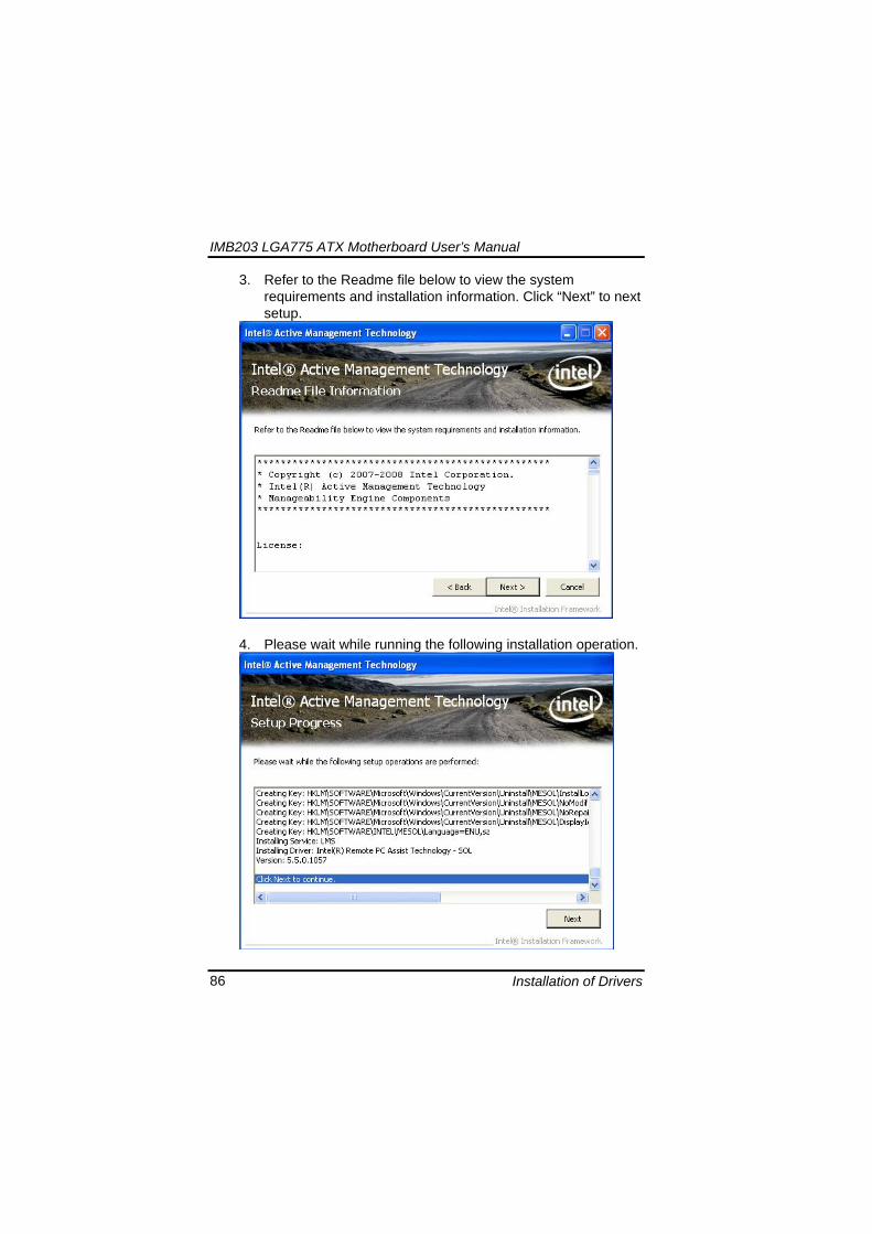
IMB203 LGA775 ATX Motherboard Userrsquos Manual
Installation of Drivers 86
3 Refer to the Readme file below to view the system requirements and installation information Click ldquoNextrdquo to next setup
4 Please wait while running the following installation operation
IMB203 LGA775 ATX Motherboard Userrsquos Manual
Installation of Drivers 87
5 Click ldquoFinishrdquo to complete the installation
IMB203 LGA775 ATX Motherboard Userrsquos Manual
Installation of Drivers 88
66 Installing MEI (Management Engine Interface) Driver
Note You must download and properly install the required NET version 35 provided from a separate downloading of the actual FimwareTools kit releases posted on VIP prior to loading the MEILMS Driver stack
1 Run the setup program to install Intelreg Management Engine
Interface onto your computer It is strongly recommended that you exit all programs before continuing Click ldquoNextrdquo to next step
格式化 字型 (符號) Arial
格式化 字型 (符號) Arial 非加寬 緊縮
IMB203 LGA775 ATX Motherboard Userrsquos Manual
Installation of Drivers 89
2 An Intelreg license agreement appears that you need to continue the setup program by clicking ldquoYesrdquo to accept the terms
IMB203 LGA775 ATX Motherboard Userrsquos Manual
Installation of Drivers 90
3 Refer to the Readme file below to view the system requirements and installation information Click ldquoNextrdquo to next setup
4 Please wait while running the following installation operation
IMB203 LGA775 ATX Motherboard Userrsquos Manual
Installation of Drivers 91
5 Click ldquoFinishrdquo to complete the installation
IMB203 LGA775 ATX Motherboard Userrsquos Manual
Installation of Drivers 92
MEMO
IMB203 LGA775 ATX Motherboard Userrsquos Manual
Watchdog Timer 93
APPENDIX A WATCHDOG TIMER
Watchdog Timer Setting After the system stops working for a while it can be auto-reset by the Watchdog Timer The integrated Watchdog Timer can be set up in the system reset mode by program
Using the Watchdog Function Start darr Un-Lock WDT O 2E 87 Un-lock super IO
O 2E 87 Un-lock super IO darr Set WDT Function O 2E 2D O 2F 20 Select Logic device O 2E 07 O 2F 08 darr Activate WDT O 2E 30
O 2F 01 Set Second or Minute O 2E F5
O 2F N N=00 or 08(See below table) darr Set base timer O 2E F6
O 2F M=000102hellipFF(Hex) Value=0 to 255 darr WDT counting
re-set timer O 2E F6
O 2F M M=000102hellipFF(See below table) darr
格式化
格式化 項目符號及編號
格式化 項目符號及編號
格式化 字型 8 點 字型色彩黑色
格式化 字型 8 點 字型色彩黑色
格式化 定位點 1257 字元左 + 不在 1012 字元 + 1386字元
格式化 字型 8 點 字型色彩黑色
格式化 定位點 1257 字元左 + 不在 134 字元 + 1362字元
格式化 字型色彩 黑色
格式化 字型色彩 黑色
刪除
IMB203 LGA775 ATX Motherboard Userrsquos Manual
Watchdog Timer 94
IF No re-set timer WDT time-out generate RESET IF to disable WDT O 2E 30
O 2F 00 Can be disable at any time
N=00
M= 00h Time-out Disable 01h Time-out occurs after 1 second 02h Time-out occurs after 2 second 03h Time-out occurs after 3 second helliphelliphelliphelliphelliphelliphelliphelliphellip FFh Time-out occurs after 255 second
N=08
M= 00h Time-out Disable 01h Time-out occurs after 1 minute 02h Time-out occurs after 2 minutes 03h Time-out occurs after 3 minutes helliphelliphelliphelliphelliphelliphelliphelliphellip
FFh Time-out occurs after 255 minutes
格式化 字型色彩 黑色
格式化 字型色彩 黑色
IMB203 LGA775 ATX Motherboard Userrsquos Manual
PCI IRQ Routing 95
APPENDIX B PCI IRQ ROUTING
PICMG PCI IRQ Routing
Device ID Slot Int
PCI Slot 0 31 0 BCDA PCI Slot 1 30 1 CDAB PCI Slot 2 29 2 DABC PCI Slot 3 28 3 ABCD
IMB203 LGA775 ATX Motherboard Userrsquos Manual
PCI IRQ Routing 96
MEMO
IMB203 LGA775 ATX Motherboard Userrsquos Manual
Configuring SATA for RAID Function 97
APPENDIX C CONFIGURING SATA FOR RAID
FUNCTION
Configuring SATA Hard Drive(s) for RAID Function (Controller IntelregICH10DODO DH only) Please follow up the steps below to configure SATA hard drive(s) (1) Install SATA hard drive(s) in your system (2) Enter the BIOS Setup to configure SATA controller mode and boot
sequence (3) Configure RAID by the RAID BIOS (4) Install the SATA controller driver during the OS installation Before you begin the SATA configuration please prepare (a) Two SATA hard drives (to ensure optimal performance it is
recommended that you use two hard drives with identical model and capacity) If you do not want to create RAID with the SATA controller you may prepare only one hard drive
(b) An empty formatted floppy disk (c) Windows XP setup disk (1) Installing SATA hard drive(s) in your system
Connect one end of the SATA signal cable to the rear of the SATA hard drive and the other end to available SATA port(s) on the board Then connect the power connector of power supply to the hard drive
(2) Configuring SATA controller mode and boot sequence by the BIOS Setup You have to make sure whether the SATA controller is configured correctly by system BIOS Setup and set up BIOS boot sequence for the SATA hard drive(s)
IMB203 LGA775 ATX Motherboard Userrsquos Manual
Configuring SATA for RAID Function 98
(2)-1-1 Turn on your system and then press the Del button to enter BIOS Setup during running POST (Power-On Self Test) If you want to create RAID just go to the Advanced Settings menuIDE configuration select the Configure SATA1 as and press ltEntergt for more options
IMB203 LGA775 ATX Motherboard Userrsquos Manual
Configuring SATA for RAID Function 99
(2)-1-2 A list of options appears please select RAID
IMB203 LGA775 ATX Motherboard Userrsquos Manual
Configuring SATA for RAID Function 100
(2)-2 Set CDROM for First Boot Device under the Boot Settings menu to boot CD-ROM after system restarts
(2)-3 Save and exit the BIOS Setup
IMB203 LGA775 ATX Motherboard Userrsquos Manual
Configuring SATA for RAID Function 101
(3) Configuring RAID by the RAID BIOS Enter the RAID BIOS setup utility to configure a RAID array Skip this step and proceed to Section 4 if you do not want to create a RAID (3)-1 After the POST memory testing and before the operating
system booting a message Press ltCtrl-Igt to enter Configuration Utility shows up accordingly press ltCTRL+ Igt to enter the RAID BIOS setup utility
(3)-2 After you press ltCTRL+ Igt the Create RAID Volume screen will appear If you want to create a RAID array select the Create RAID Volume option in the Main Menu and press ENTER
IMB203 LGA775 ATX Motherboard Userrsquos Manual
Configuring SATA for RAID Function 102
(3)-3-1 After entering the CREATE VOLUME MENU screen you can type the disk array name with 1~16 letters (letters cannot be special characters) in the item ldquoNamerdquo
(3)-3-2 When finished press ENTER to select a RAID level There are three RAID levels RAID0 RAID1 and RAID5 amp RAID10 Select a RAID level and press ENTER
IMB203 LGA775 ATX Motherboard Userrsquos Manual
Configuring SATA for RAID Function 103
(3)-4 Set the stripe block size The KB is the standard unit of stripe block size The stripe block size can be 4KB to 128KB After the setting press ENTER for the array capacity
(3)-5 After setting all the items on the menu select Create Volume
and press ENTER to start creating the RAID array
IMB203 LGA775 ATX Motherboard Userrsquos Manual
Configuring SATA for RAID Function 104
(3)-6 When prompting the confirmation press ldquoYldquo to create this volume or ldquoNldquo to cancel the creation
After the creation is completed you can see detailed information about the RAID Array in the DISKVOLUME INFORMATION section including RAID mode disk block size disk name and disk capacity etc
IMB203 LGA775 ATX Motherboard Userrsquos Manual
Configuring SATA for RAID Function 105
Delete RAID Volume If you want to delete a RAID volume select the Delete RAID Volume option in Main Menu Press ENTER and follow on-screen instructions
Please press [ESC] to exit the RAID BIOS utility Now you can proceed to install a SATA driver controller and the operating system
IMB203 LGA775 ATX Motherboard Userrsquos Manual
Configuring SATA for RAID Function 106
(4) Making a SATA Driver Disk To install the operating system onto a serial ATA hard disk successfully you need to install the SATA controller driver during the OS installation Without the driver the hard disk may not be recognized during the Windows setup process First of all please format a blank floppy disk Secondly follow up these steps below to produce a SATA driver disk Users can insert the Driver CD and the formatted blank floppy disk in another system And then please copy all of file of the f6flpy32 folder in the Driver CD to a floppy disk Note Please copy all of file of the f6flpy64 folder if installing 64-bit
Windows Operating System
IMB203 LGA775 ATX Motherboard Userrsquos Manual
Configuring SATA for RAID Function 107
(5) Installing the SATA controller driver during the OS installation Now the SATA driver disk is ready and BIOS settings configured you can proceed to install Windows 2000XP onto your SATA hard drive using the SATA driver Here is an example for Windows XP installation (5)-1 Restart your system to boot the Windows 2000XP Setup disk
and press F6 button as soon as you see the message Press F6 if you need to install a 3rd party SCSI or RAID driver After pressing the F6 button there will be a few moments for some files being loaded before next screen appears
IMB203 LGA775 ATX Motherboard Userrsquos Manual
Configuring SATA for RAID Function 108
(5)-2 When you see the screen below insert the floppy disk containing the SATA driver and press ldquoSrdquo
(5)-3 If the Setup correctly recognizes the driver of the floppy disk
a controller menu will appear below Use the ARROW keys to select Intel(R) ICH8RICH9RICH10RDO SATA RAID Controller and press ENTER Then it will begin to load the SATA driver from the floppy disk
IMB203 LGA775 ATX Motherboard Userrsquos Manual
Configuring SATA for RAID Function 109
Note If a message on the screen saying that one or some file(s) cannot be found please check the floppy disk or copy the correct SATA driver again from the driver CD
IMB203 LGA775 ATX Motherboard Userrsquos Manual
Configuring SATA for RAID Function 110
MEMO
IMB203 LGA775 ATX Motherboard Userrsquos Manual
iAMT Settings 111
APPENDIX D iAMT SETTINGS
The Intelreg Active Management Technology (Intelreg iAMT) has decreased a major barrier to IT efficiency that uses built-in platform capabilities and popular third-party management and security applications to allow IT a better discovering healing and protection their networked computing assets In order to utilize Intel iAMT you must enter the ME BIOS (CTRL + P during system startup) change the ME BIOS password and then select ldquoIntelreg iAMTrdquo as the manageability feature
D1 Entering MEBx 1 You must go to BIOS TO start iAMT function 2 Exit from BIOS after starting iAMT and press Ctrl+P to enter MEBx Setting
It is better to press Ctrl+P before the screen popping out
格式化
IMB203 LGA775 ATX Motherboard Userrsquos Manual
iAMT Settings 112
D2 Set amp Change Password 1 You will be asked to set a password when first log in The default
password is lsquoadminrsquo
2 You will be asked to change the password before setting ME
Change Password
IMB203 LGA775 ATX Motherboard Userrsquos Manual
iAMT Settings 113
3 You must confirm your new password while revising (as Remark 1)
Remark 1 The new password must contain (example 11qqQQ) (default value)
Eight characters
One upper case
One lower case
One number
One special symbol such as $ or
( excepted)
Underline ( _ ) and space are valid characters for password but they wonrsquot make higher complexity
IMB203 LGA775 ATX Motherboard Userrsquos Manual
iAMT Settings 114
D3 Intelreg iAMT Settings 1 Select Intelreg iAMT Configuration and press ltENTERgt
2 Key in the Host Name If Intelreg iAMT set to lsquoDHCPlsquo the Host name must be identical to the operating system mechanic
IMB203 LGA775 ATX Motherboard Userrsquos Manual
iAMT Settings 115
3 Select TCPIP to get into Network interface and set it to lsquoENABLEDrsquo into DHCP Mode and set it to lsquoDISABLEDrsquo (as Remark 2) into Domain name and set the Intel Management Engine domain name such as lsquoAMTintelcomrsquo
(3-1)
(3-2)
IMB203 LGA775 ATX Motherboard Userrsquos Manual
iAMT Settings 116
Remark 2 DHCP Mode lsquoDISABLEDlsquo if DHCP Mode is disabled you can make the following settings
IP address
Subnet mask
IMB203 LGA775 ATX Motherboard Userrsquos Manual
iAMT Settings 117
Default Gateway address
Preferred DNS address
IMB203 LGA775 ATX Motherboard Userrsquos Manual
iAMT Settings 118
Alternate DNS address
Domain name
4 Exit from MEBx after completing the iAMT settings
IMB203 LGA775 ATX Motherboard Userrsquos Manual
iAMT Settings 119
D4 iAMT Web Console 1 From a web browser please type http(IP ADDRESS)16992
which connects to iAMT Web Example http1014021416992
2 To log on you will be required to type in username and password
for access to the Web
USER admin (default value)
PASS (MEBx password)
IMB203 LGA775 ATX Motherboard Userrsquos Manual
iAMT Settings 120
3 Enter the iAMT Web
4 Click Remote Control and select commands on the right side
IMB203 LGA775 ATX Motherboard Userrsquos Manual
iAMT Settings 121
5 When you have finished using the iAMT Web console close the Web browser
IMB203 LGA775 ATX Motherboard Userrsquos Manual
iAMT Settings 122
MEMO
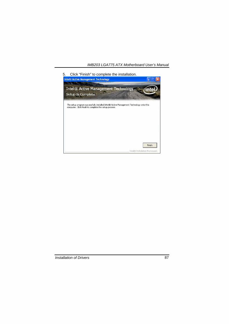
IMB203 LGA775 ATX Motherboard Userrsquos Manual
Installation of Drivers 88
66 Installing MEI (Management Engine Interface) Driver
Note You must download and properly install the required NET version 35 provided from a separate downloading of the actual FimwareTools kit releases posted on VIP prior to loading the MEILMS Driver stack
1 Run the setup program to install Intelreg Management Engine
Interface onto your computer It is strongly recommended that you exit all programs before continuing Click ldquoNextrdquo to next step
格式化 字型 (符號) Arial
格式化 字型 (符號) Arial 非加寬 緊縮
IMB203 LGA775 ATX Motherboard Userrsquos Manual
Installation of Drivers 89
2 An Intelreg license agreement appears that you need to continue the setup program by clicking ldquoYesrdquo to accept the terms
IMB203 LGA775 ATX Motherboard Userrsquos Manual
Installation of Drivers 90
3 Refer to the Readme file below to view the system requirements and installation information Click ldquoNextrdquo to next setup
4 Please wait while running the following installation operation
IMB203 LGA775 ATX Motherboard Userrsquos Manual
Installation of Drivers 91
5 Click ldquoFinishrdquo to complete the installation
IMB203 LGA775 ATX Motherboard Userrsquos Manual
Installation of Drivers 92
MEMO
IMB203 LGA775 ATX Motherboard Userrsquos Manual
Watchdog Timer 93
APPENDIX A WATCHDOG TIMER
Watchdog Timer Setting After the system stops working for a while it can be auto-reset by the Watchdog Timer The integrated Watchdog Timer can be set up in the system reset mode by program
Using the Watchdog Function Start darr Un-Lock WDT O 2E 87 Un-lock super IO
O 2E 87 Un-lock super IO darr Set WDT Function O 2E 2D O 2F 20 Select Logic device O 2E 07 O 2F 08 darr Activate WDT O 2E 30
O 2F 01 Set Second or Minute O 2E F5
O 2F N N=00 or 08(See below table) darr Set base timer O 2E F6
O 2F M=000102hellipFF(Hex) Value=0 to 255 darr WDT counting
re-set timer O 2E F6
O 2F M M=000102hellipFF(See below table) darr
格式化
格式化 項目符號及編號
格式化 項目符號及編號
格式化 字型 8 點 字型色彩黑色
格式化 字型 8 點 字型色彩黑色
格式化 定位點 1257 字元左 + 不在 1012 字元 + 1386字元
格式化 字型 8 點 字型色彩黑色
格式化 定位點 1257 字元左 + 不在 134 字元 + 1362字元
格式化 字型色彩 黑色
格式化 字型色彩 黑色
刪除
IMB203 LGA775 ATX Motherboard Userrsquos Manual
Watchdog Timer 94
IF No re-set timer WDT time-out generate RESET IF to disable WDT O 2E 30
O 2F 00 Can be disable at any time
N=00
M= 00h Time-out Disable 01h Time-out occurs after 1 second 02h Time-out occurs after 2 second 03h Time-out occurs after 3 second helliphelliphelliphelliphelliphelliphelliphelliphellip FFh Time-out occurs after 255 second
N=08
M= 00h Time-out Disable 01h Time-out occurs after 1 minute 02h Time-out occurs after 2 minutes 03h Time-out occurs after 3 minutes helliphelliphelliphelliphelliphelliphelliphelliphellip
FFh Time-out occurs after 255 minutes
格式化 字型色彩 黑色
格式化 字型色彩 黑色
IMB203 LGA775 ATX Motherboard Userrsquos Manual
PCI IRQ Routing 95
APPENDIX B PCI IRQ ROUTING
PICMG PCI IRQ Routing
Device ID Slot Int
PCI Slot 0 31 0 BCDA PCI Slot 1 30 1 CDAB PCI Slot 2 29 2 DABC PCI Slot 3 28 3 ABCD
IMB203 LGA775 ATX Motherboard Userrsquos Manual
PCI IRQ Routing 96
MEMO
IMB203 LGA775 ATX Motherboard Userrsquos Manual
Configuring SATA for RAID Function 97
APPENDIX C CONFIGURING SATA FOR RAID
FUNCTION
Configuring SATA Hard Drive(s) for RAID Function (Controller IntelregICH10DODO DH only) Please follow up the steps below to configure SATA hard drive(s) (1) Install SATA hard drive(s) in your system (2) Enter the BIOS Setup to configure SATA controller mode and boot
sequence (3) Configure RAID by the RAID BIOS (4) Install the SATA controller driver during the OS installation Before you begin the SATA configuration please prepare (a) Two SATA hard drives (to ensure optimal performance it is
recommended that you use two hard drives with identical model and capacity) If you do not want to create RAID with the SATA controller you may prepare only one hard drive
(b) An empty formatted floppy disk (c) Windows XP setup disk (1) Installing SATA hard drive(s) in your system
Connect one end of the SATA signal cable to the rear of the SATA hard drive and the other end to available SATA port(s) on the board Then connect the power connector of power supply to the hard drive
(2) Configuring SATA controller mode and boot sequence by the BIOS Setup You have to make sure whether the SATA controller is configured correctly by system BIOS Setup and set up BIOS boot sequence for the SATA hard drive(s)
IMB203 LGA775 ATX Motherboard Userrsquos Manual
Configuring SATA for RAID Function 98
(2)-1-1 Turn on your system and then press the Del button to enter BIOS Setup during running POST (Power-On Self Test) If you want to create RAID just go to the Advanced Settings menuIDE configuration select the Configure SATA1 as and press ltEntergt for more options
IMB203 LGA775 ATX Motherboard Userrsquos Manual
Configuring SATA for RAID Function 99
(2)-1-2 A list of options appears please select RAID
IMB203 LGA775 ATX Motherboard Userrsquos Manual
Configuring SATA for RAID Function 100
(2)-2 Set CDROM for First Boot Device under the Boot Settings menu to boot CD-ROM after system restarts
(2)-3 Save and exit the BIOS Setup
IMB203 LGA775 ATX Motherboard Userrsquos Manual
Configuring SATA for RAID Function 101
(3) Configuring RAID by the RAID BIOS Enter the RAID BIOS setup utility to configure a RAID array Skip this step and proceed to Section 4 if you do not want to create a RAID (3)-1 After the POST memory testing and before the operating
system booting a message Press ltCtrl-Igt to enter Configuration Utility shows up accordingly press ltCTRL+ Igt to enter the RAID BIOS setup utility
(3)-2 After you press ltCTRL+ Igt the Create RAID Volume screen will appear If you want to create a RAID array select the Create RAID Volume option in the Main Menu and press ENTER
IMB203 LGA775 ATX Motherboard Userrsquos Manual
Configuring SATA for RAID Function 102
(3)-3-1 After entering the CREATE VOLUME MENU screen you can type the disk array name with 1~16 letters (letters cannot be special characters) in the item ldquoNamerdquo
(3)-3-2 When finished press ENTER to select a RAID level There are three RAID levels RAID0 RAID1 and RAID5 amp RAID10 Select a RAID level and press ENTER
IMB203 LGA775 ATX Motherboard Userrsquos Manual
Configuring SATA for RAID Function 103
(3)-4 Set the stripe block size The KB is the standard unit of stripe block size The stripe block size can be 4KB to 128KB After the setting press ENTER for the array capacity
(3)-5 After setting all the items on the menu select Create Volume
and press ENTER to start creating the RAID array
IMB203 LGA775 ATX Motherboard Userrsquos Manual
Configuring SATA for RAID Function 104
(3)-6 When prompting the confirmation press ldquoYldquo to create this volume or ldquoNldquo to cancel the creation
After the creation is completed you can see detailed information about the RAID Array in the DISKVOLUME INFORMATION section including RAID mode disk block size disk name and disk capacity etc
IMB203 LGA775 ATX Motherboard Userrsquos Manual
Configuring SATA for RAID Function 105
Delete RAID Volume If you want to delete a RAID volume select the Delete RAID Volume option in Main Menu Press ENTER and follow on-screen instructions
Please press [ESC] to exit the RAID BIOS utility Now you can proceed to install a SATA driver controller and the operating system
IMB203 LGA775 ATX Motherboard Userrsquos Manual
Configuring SATA for RAID Function 106
(4) Making a SATA Driver Disk To install the operating system onto a serial ATA hard disk successfully you need to install the SATA controller driver during the OS installation Without the driver the hard disk may not be recognized during the Windows setup process First of all please format a blank floppy disk Secondly follow up these steps below to produce a SATA driver disk Users can insert the Driver CD and the formatted blank floppy disk in another system And then please copy all of file of the f6flpy32 folder in the Driver CD to a floppy disk Note Please copy all of file of the f6flpy64 folder if installing 64-bit
Windows Operating System
IMB203 LGA775 ATX Motherboard Userrsquos Manual
Configuring SATA for RAID Function 107
(5) Installing the SATA controller driver during the OS installation Now the SATA driver disk is ready and BIOS settings configured you can proceed to install Windows 2000XP onto your SATA hard drive using the SATA driver Here is an example for Windows XP installation (5)-1 Restart your system to boot the Windows 2000XP Setup disk
and press F6 button as soon as you see the message Press F6 if you need to install a 3rd party SCSI or RAID driver After pressing the F6 button there will be a few moments for some files being loaded before next screen appears
IMB203 LGA775 ATX Motherboard Userrsquos Manual
Configuring SATA for RAID Function 108
(5)-2 When you see the screen below insert the floppy disk containing the SATA driver and press ldquoSrdquo
(5)-3 If the Setup correctly recognizes the driver of the floppy disk
a controller menu will appear below Use the ARROW keys to select Intel(R) ICH8RICH9RICH10RDO SATA RAID Controller and press ENTER Then it will begin to load the SATA driver from the floppy disk
IMB203 LGA775 ATX Motherboard Userrsquos Manual
Configuring SATA for RAID Function 109
Note If a message on the screen saying that one or some file(s) cannot be found please check the floppy disk or copy the correct SATA driver again from the driver CD
IMB203 LGA775 ATX Motherboard Userrsquos Manual
Configuring SATA for RAID Function 110
MEMO
IMB203 LGA775 ATX Motherboard Userrsquos Manual
iAMT Settings 111
APPENDIX D iAMT SETTINGS
The Intelreg Active Management Technology (Intelreg iAMT) has decreased a major barrier to IT efficiency that uses built-in platform capabilities and popular third-party management and security applications to allow IT a better discovering healing and protection their networked computing assets In order to utilize Intel iAMT you must enter the ME BIOS (CTRL + P during system startup) change the ME BIOS password and then select ldquoIntelreg iAMTrdquo as the manageability feature
D1 Entering MEBx 1 You must go to BIOS TO start iAMT function 2 Exit from BIOS after starting iAMT and press Ctrl+P to enter MEBx Setting
It is better to press Ctrl+P before the screen popping out
格式化
IMB203 LGA775 ATX Motherboard Userrsquos Manual
iAMT Settings 112
D2 Set amp Change Password 1 You will be asked to set a password when first log in The default
password is lsquoadminrsquo
2 You will be asked to change the password before setting ME
Change Password
IMB203 LGA775 ATX Motherboard Userrsquos Manual
iAMT Settings 113
3 You must confirm your new password while revising (as Remark 1)
Remark 1 The new password must contain (example 11qqQQ) (default value)
Eight characters
One upper case
One lower case
One number
One special symbol such as $ or
( excepted)
Underline ( _ ) and space are valid characters for password but they wonrsquot make higher complexity
IMB203 LGA775 ATX Motherboard Userrsquos Manual
iAMT Settings 114
D3 Intelreg iAMT Settings 1 Select Intelreg iAMT Configuration and press ltENTERgt
2 Key in the Host Name If Intelreg iAMT set to lsquoDHCPlsquo the Host name must be identical to the operating system mechanic
IMB203 LGA775 ATX Motherboard Userrsquos Manual
iAMT Settings 115
3 Select TCPIP to get into Network interface and set it to lsquoENABLEDrsquo into DHCP Mode and set it to lsquoDISABLEDrsquo (as Remark 2) into Domain name and set the Intel Management Engine domain name such as lsquoAMTintelcomrsquo
(3-1)
(3-2)
IMB203 LGA775 ATX Motherboard Userrsquos Manual
iAMT Settings 116
Remark 2 DHCP Mode lsquoDISABLEDlsquo if DHCP Mode is disabled you can make the following settings
IP address
Subnet mask
IMB203 LGA775 ATX Motherboard Userrsquos Manual
iAMT Settings 117
Default Gateway address
Preferred DNS address
IMB203 LGA775 ATX Motherboard Userrsquos Manual
iAMT Settings 118
Alternate DNS address
Domain name
4 Exit from MEBx after completing the iAMT settings
IMB203 LGA775 ATX Motherboard Userrsquos Manual
iAMT Settings 119
D4 iAMT Web Console 1 From a web browser please type http(IP ADDRESS)16992
which connects to iAMT Web Example http1014021416992
2 To log on you will be required to type in username and password
for access to the Web
USER admin (default value)
PASS (MEBx password)
IMB203 LGA775 ATX Motherboard Userrsquos Manual
iAMT Settings 120
3 Enter the iAMT Web
4 Click Remote Control and select commands on the right side
IMB203 LGA775 ATX Motherboard Userrsquos Manual
iAMT Settings 121
5 When you have finished using the iAMT Web console close the Web browser
IMB203 LGA775 ATX Motherboard Userrsquos Manual
iAMT Settings 122
MEMO
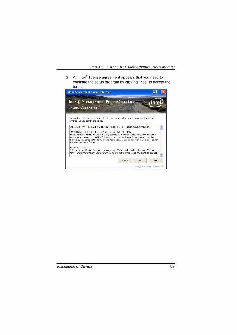
IMB203 LGA775 ATX Motherboard Userrsquos Manual
Installation of Drivers 90
3 Refer to the Readme file below to view the system requirements and installation information Click ldquoNextrdquo to next setup
4 Please wait while running the following installation operation
IMB203 LGA775 ATX Motherboard Userrsquos Manual
Installation of Drivers 91
5 Click ldquoFinishrdquo to complete the installation
IMB203 LGA775 ATX Motherboard Userrsquos Manual
Installation of Drivers 92
MEMO
IMB203 LGA775 ATX Motherboard Userrsquos Manual
Watchdog Timer 93
APPENDIX A WATCHDOG TIMER
Watchdog Timer Setting After the system stops working for a while it can be auto-reset by the Watchdog Timer The integrated Watchdog Timer can be set up in the system reset mode by program
Using the Watchdog Function Start darr Un-Lock WDT O 2E 87 Un-lock super IO
O 2E 87 Un-lock super IO darr Set WDT Function O 2E 2D O 2F 20 Select Logic device O 2E 07 O 2F 08 darr Activate WDT O 2E 30
O 2F 01 Set Second or Minute O 2E F5
O 2F N N=00 or 08(See below table) darr Set base timer O 2E F6
O 2F M=000102hellipFF(Hex) Value=0 to 255 darr WDT counting
re-set timer O 2E F6
O 2F M M=000102hellipFF(See below table) darr
格式化
格式化 項目符號及編號
格式化 項目符號及編號
格式化 字型 8 點 字型色彩黑色
格式化 字型 8 點 字型色彩黑色
格式化 定位點 1257 字元左 + 不在 1012 字元 + 1386字元
格式化 字型 8 點 字型色彩黑色
格式化 定位點 1257 字元左 + 不在 134 字元 + 1362字元
格式化 字型色彩 黑色
格式化 字型色彩 黑色
刪除
IMB203 LGA775 ATX Motherboard Userrsquos Manual
Watchdog Timer 94
IF No re-set timer WDT time-out generate RESET IF to disable WDT O 2E 30
O 2F 00 Can be disable at any time
N=00
M= 00h Time-out Disable 01h Time-out occurs after 1 second 02h Time-out occurs after 2 second 03h Time-out occurs after 3 second helliphelliphelliphelliphelliphelliphelliphelliphellip FFh Time-out occurs after 255 second
N=08
M= 00h Time-out Disable 01h Time-out occurs after 1 minute 02h Time-out occurs after 2 minutes 03h Time-out occurs after 3 minutes helliphelliphelliphelliphelliphelliphelliphelliphellip
FFh Time-out occurs after 255 minutes
格式化 字型色彩 黑色
格式化 字型色彩 黑色
IMB203 LGA775 ATX Motherboard Userrsquos Manual
PCI IRQ Routing 95
APPENDIX B PCI IRQ ROUTING
PICMG PCI IRQ Routing
Device ID Slot Int
PCI Slot 0 31 0 BCDA PCI Slot 1 30 1 CDAB PCI Slot 2 29 2 DABC PCI Slot 3 28 3 ABCD
IMB203 LGA775 ATX Motherboard Userrsquos Manual
PCI IRQ Routing 96
MEMO
IMB203 LGA775 ATX Motherboard Userrsquos Manual
Configuring SATA for RAID Function 97
APPENDIX C CONFIGURING SATA FOR RAID
FUNCTION
Configuring SATA Hard Drive(s) for RAID Function (Controller IntelregICH10DODO DH only) Please follow up the steps below to configure SATA hard drive(s) (1) Install SATA hard drive(s) in your system (2) Enter the BIOS Setup to configure SATA controller mode and boot
sequence (3) Configure RAID by the RAID BIOS (4) Install the SATA controller driver during the OS installation Before you begin the SATA configuration please prepare (a) Two SATA hard drives (to ensure optimal performance it is
recommended that you use two hard drives with identical model and capacity) If you do not want to create RAID with the SATA controller you may prepare only one hard drive
(b) An empty formatted floppy disk (c) Windows XP setup disk (1) Installing SATA hard drive(s) in your system
Connect one end of the SATA signal cable to the rear of the SATA hard drive and the other end to available SATA port(s) on the board Then connect the power connector of power supply to the hard drive
(2) Configuring SATA controller mode and boot sequence by the BIOS Setup You have to make sure whether the SATA controller is configured correctly by system BIOS Setup and set up BIOS boot sequence for the SATA hard drive(s)
IMB203 LGA775 ATX Motherboard Userrsquos Manual
Configuring SATA for RAID Function 98
(2)-1-1 Turn on your system and then press the Del button to enter BIOS Setup during running POST (Power-On Self Test) If you want to create RAID just go to the Advanced Settings menuIDE configuration select the Configure SATA1 as and press ltEntergt for more options
IMB203 LGA775 ATX Motherboard Userrsquos Manual
Configuring SATA for RAID Function 99
(2)-1-2 A list of options appears please select RAID
IMB203 LGA775 ATX Motherboard Userrsquos Manual
Configuring SATA for RAID Function 100
(2)-2 Set CDROM for First Boot Device under the Boot Settings menu to boot CD-ROM after system restarts
(2)-3 Save and exit the BIOS Setup
IMB203 LGA775 ATX Motherboard Userrsquos Manual
Configuring SATA for RAID Function 101
(3) Configuring RAID by the RAID BIOS Enter the RAID BIOS setup utility to configure a RAID array Skip this step and proceed to Section 4 if you do not want to create a RAID (3)-1 After the POST memory testing and before the operating
system booting a message Press ltCtrl-Igt to enter Configuration Utility shows up accordingly press ltCTRL+ Igt to enter the RAID BIOS setup utility
(3)-2 After you press ltCTRL+ Igt the Create RAID Volume screen will appear If you want to create a RAID array select the Create RAID Volume option in the Main Menu and press ENTER
IMB203 LGA775 ATX Motherboard Userrsquos Manual
Configuring SATA for RAID Function 102
(3)-3-1 After entering the CREATE VOLUME MENU screen you can type the disk array name with 1~16 letters (letters cannot be special characters) in the item ldquoNamerdquo
(3)-3-2 When finished press ENTER to select a RAID level There are three RAID levels RAID0 RAID1 and RAID5 amp RAID10 Select a RAID level and press ENTER
IMB203 LGA775 ATX Motherboard Userrsquos Manual
Configuring SATA for RAID Function 103
(3)-4 Set the stripe block size The KB is the standard unit of stripe block size The stripe block size can be 4KB to 128KB After the setting press ENTER for the array capacity
(3)-5 After setting all the items on the menu select Create Volume
and press ENTER to start creating the RAID array
IMB203 LGA775 ATX Motherboard Userrsquos Manual
Configuring SATA for RAID Function 104
(3)-6 When prompting the confirmation press ldquoYldquo to create this volume or ldquoNldquo to cancel the creation
After the creation is completed you can see detailed information about the RAID Array in the DISKVOLUME INFORMATION section including RAID mode disk block size disk name and disk capacity etc
IMB203 LGA775 ATX Motherboard Userrsquos Manual
Configuring SATA for RAID Function 105
Delete RAID Volume If you want to delete a RAID volume select the Delete RAID Volume option in Main Menu Press ENTER and follow on-screen instructions
Please press [ESC] to exit the RAID BIOS utility Now you can proceed to install a SATA driver controller and the operating system
IMB203 LGA775 ATX Motherboard Userrsquos Manual
Configuring SATA for RAID Function 106
(4) Making a SATA Driver Disk To install the operating system onto a serial ATA hard disk successfully you need to install the SATA controller driver during the OS installation Without the driver the hard disk may not be recognized during the Windows setup process First of all please format a blank floppy disk Secondly follow up these steps below to produce a SATA driver disk Users can insert the Driver CD and the formatted blank floppy disk in another system And then please copy all of file of the f6flpy32 folder in the Driver CD to a floppy disk Note Please copy all of file of the f6flpy64 folder if installing 64-bit
Windows Operating System
IMB203 LGA775 ATX Motherboard Userrsquos Manual
Configuring SATA for RAID Function 107
(5) Installing the SATA controller driver during the OS installation Now the SATA driver disk is ready and BIOS settings configured you can proceed to install Windows 2000XP onto your SATA hard drive using the SATA driver Here is an example for Windows XP installation (5)-1 Restart your system to boot the Windows 2000XP Setup disk
and press F6 button as soon as you see the message Press F6 if you need to install a 3rd party SCSI or RAID driver After pressing the F6 button there will be a few moments for some files being loaded before next screen appears
IMB203 LGA775 ATX Motherboard Userrsquos Manual
Configuring SATA for RAID Function 108
(5)-2 When you see the screen below insert the floppy disk containing the SATA driver and press ldquoSrdquo
(5)-3 If the Setup correctly recognizes the driver of the floppy disk
a controller menu will appear below Use the ARROW keys to select Intel(R) ICH8RICH9RICH10RDO SATA RAID Controller and press ENTER Then it will begin to load the SATA driver from the floppy disk
IMB203 LGA775 ATX Motherboard Userrsquos Manual
Configuring SATA for RAID Function 109
Note If a message on the screen saying that one or some file(s) cannot be found please check the floppy disk or copy the correct SATA driver again from the driver CD
IMB203 LGA775 ATX Motherboard Userrsquos Manual
Configuring SATA for RAID Function 110
MEMO
IMB203 LGA775 ATX Motherboard Userrsquos Manual
iAMT Settings 111
APPENDIX D iAMT SETTINGS
The Intelreg Active Management Technology (Intelreg iAMT) has decreased a major barrier to IT efficiency that uses built-in platform capabilities and popular third-party management and security applications to allow IT a better discovering healing and protection their networked computing assets In order to utilize Intel iAMT you must enter the ME BIOS (CTRL + P during system startup) change the ME BIOS password and then select ldquoIntelreg iAMTrdquo as the manageability feature
D1 Entering MEBx 1 You must go to BIOS TO start iAMT function 2 Exit from BIOS after starting iAMT and press Ctrl+P to enter MEBx Setting
It is better to press Ctrl+P before the screen popping out
格式化
IMB203 LGA775 ATX Motherboard Userrsquos Manual
iAMT Settings 112
D2 Set amp Change Password 1 You will be asked to set a password when first log in The default
password is lsquoadminrsquo
2 You will be asked to change the password before setting ME
Change Password
IMB203 LGA775 ATX Motherboard Userrsquos Manual
iAMT Settings 113
3 You must confirm your new password while revising (as Remark 1)
Remark 1 The new password must contain (example 11qqQQ) (default value)
Eight characters
One upper case
One lower case
One number
One special symbol such as $ or
( excepted)
Underline ( _ ) and space are valid characters for password but they wonrsquot make higher complexity
IMB203 LGA775 ATX Motherboard Userrsquos Manual
iAMT Settings 114
D3 Intelreg iAMT Settings 1 Select Intelreg iAMT Configuration and press ltENTERgt
2 Key in the Host Name If Intelreg iAMT set to lsquoDHCPlsquo the Host name must be identical to the operating system mechanic
IMB203 LGA775 ATX Motherboard Userrsquos Manual
iAMT Settings 115
3 Select TCPIP to get into Network interface and set it to lsquoENABLEDrsquo into DHCP Mode and set it to lsquoDISABLEDrsquo (as Remark 2) into Domain name and set the Intel Management Engine domain name such as lsquoAMTintelcomrsquo
(3-1)
(3-2)
IMB203 LGA775 ATX Motherboard Userrsquos Manual
iAMT Settings 116
Remark 2 DHCP Mode lsquoDISABLEDlsquo if DHCP Mode is disabled you can make the following settings
IP address
Subnet mask
IMB203 LGA775 ATX Motherboard Userrsquos Manual
iAMT Settings 117
Default Gateway address
Preferred DNS address
IMB203 LGA775 ATX Motherboard Userrsquos Manual
iAMT Settings 118
Alternate DNS address
Domain name
4 Exit from MEBx after completing the iAMT settings
IMB203 LGA775 ATX Motherboard Userrsquos Manual
iAMT Settings 119
D4 iAMT Web Console 1 From a web browser please type http(IP ADDRESS)16992
which connects to iAMT Web Example http1014021416992
2 To log on you will be required to type in username and password
for access to the Web
USER admin (default value)
PASS (MEBx password)
IMB203 LGA775 ATX Motherboard Userrsquos Manual
iAMT Settings 120
3 Enter the iAMT Web
4 Click Remote Control and select commands on the right side
IMB203 LGA775 ATX Motherboard Userrsquos Manual
iAMT Settings 121
5 When you have finished using the iAMT Web console close the Web browser
IMB203 LGA775 ATX Motherboard Userrsquos Manual
iAMT Settings 122
MEMO
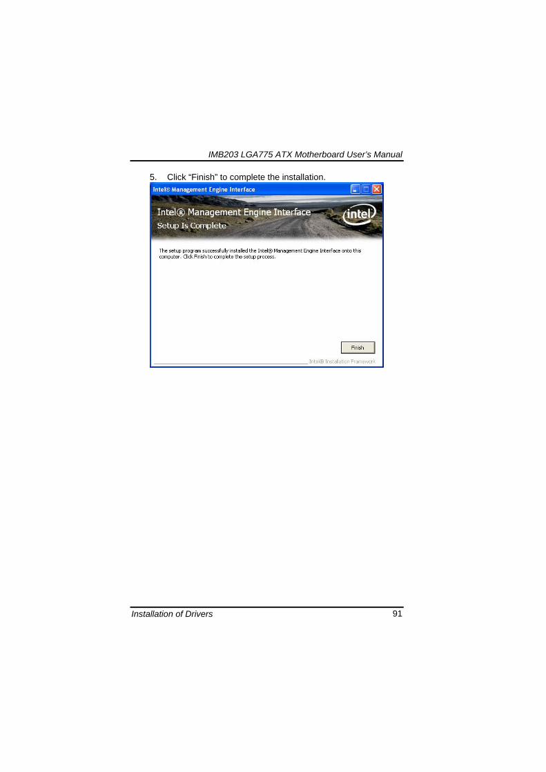
IMB203 LGA775 ATX Motherboard Userrsquos Manual
Watchdog Timer 93
APPENDIX A WATCHDOG TIMER
Watchdog Timer Setting After the system stops working for a while it can be auto-reset by the Watchdog Timer The integrated Watchdog Timer can be set up in the system reset mode by program
Using the Watchdog Function Start darr Un-Lock WDT O 2E 87 Un-lock super IO
O 2E 87 Un-lock super IO darr Set WDT Function O 2E 2D O 2F 20 Select Logic device O 2E 07 O 2F 08 darr Activate WDT O 2E 30
O 2F 01 Set Second or Minute O 2E F5
O 2F N N=00 or 08(See below table) darr Set base timer O 2E F6
O 2F M=000102hellipFF(Hex) Value=0 to 255 darr WDT counting
re-set timer O 2E F6
O 2F M M=000102hellipFF(See below table) darr
格式化
格式化 項目符號及編號
格式化 項目符號及編號
格式化 字型 8 點 字型色彩黑色
格式化 字型 8 點 字型色彩黑色
格式化 定位點 1257 字元左 + 不在 1012 字元 + 1386字元
格式化 字型 8 點 字型色彩黑色
格式化 定位點 1257 字元左 + 不在 134 字元 + 1362字元
格式化 字型色彩 黑色
格式化 字型色彩 黑色
刪除
IMB203 LGA775 ATX Motherboard Userrsquos Manual
Watchdog Timer 94
IF No re-set timer WDT time-out generate RESET IF to disable WDT O 2E 30
O 2F 00 Can be disable at any time
N=00
M= 00h Time-out Disable 01h Time-out occurs after 1 second 02h Time-out occurs after 2 second 03h Time-out occurs after 3 second helliphelliphelliphelliphelliphelliphelliphelliphellip FFh Time-out occurs after 255 second
N=08
M= 00h Time-out Disable 01h Time-out occurs after 1 minute 02h Time-out occurs after 2 minutes 03h Time-out occurs after 3 minutes helliphelliphelliphelliphelliphelliphelliphelliphellip
FFh Time-out occurs after 255 minutes
格式化 字型色彩 黑色
格式化 字型色彩 黑色
IMB203 LGA775 ATX Motherboard Userrsquos Manual
PCI IRQ Routing 95
APPENDIX B PCI IRQ ROUTING
PICMG PCI IRQ Routing
Device ID Slot Int
PCI Slot 0 31 0 BCDA PCI Slot 1 30 1 CDAB PCI Slot 2 29 2 DABC PCI Slot 3 28 3 ABCD
IMB203 LGA775 ATX Motherboard Userrsquos Manual
PCI IRQ Routing 96
MEMO
IMB203 LGA775 ATX Motherboard Userrsquos Manual
Configuring SATA for RAID Function 97
APPENDIX C CONFIGURING SATA FOR RAID
FUNCTION
Configuring SATA Hard Drive(s) for RAID Function (Controller IntelregICH10DODO DH only) Please follow up the steps below to configure SATA hard drive(s) (1) Install SATA hard drive(s) in your system (2) Enter the BIOS Setup to configure SATA controller mode and boot
sequence (3) Configure RAID by the RAID BIOS (4) Install the SATA controller driver during the OS installation Before you begin the SATA configuration please prepare (a) Two SATA hard drives (to ensure optimal performance it is
recommended that you use two hard drives with identical model and capacity) If you do not want to create RAID with the SATA controller you may prepare only one hard drive
(b) An empty formatted floppy disk (c) Windows XP setup disk (1) Installing SATA hard drive(s) in your system
Connect one end of the SATA signal cable to the rear of the SATA hard drive and the other end to available SATA port(s) on the board Then connect the power connector of power supply to the hard drive
(2) Configuring SATA controller mode and boot sequence by the BIOS Setup You have to make sure whether the SATA controller is configured correctly by system BIOS Setup and set up BIOS boot sequence for the SATA hard drive(s)
IMB203 LGA775 ATX Motherboard Userrsquos Manual
Configuring SATA for RAID Function 98
(2)-1-1 Turn on your system and then press the Del button to enter BIOS Setup during running POST (Power-On Self Test) If you want to create RAID just go to the Advanced Settings menuIDE configuration select the Configure SATA1 as and press ltEntergt for more options
IMB203 LGA775 ATX Motherboard Userrsquos Manual
Configuring SATA for RAID Function 99
(2)-1-2 A list of options appears please select RAID
IMB203 LGA775 ATX Motherboard Userrsquos Manual
Configuring SATA for RAID Function 100
(2)-2 Set CDROM for First Boot Device under the Boot Settings menu to boot CD-ROM after system restarts
(2)-3 Save and exit the BIOS Setup
IMB203 LGA775 ATX Motherboard Userrsquos Manual
Configuring SATA for RAID Function 101
(3) Configuring RAID by the RAID BIOS Enter the RAID BIOS setup utility to configure a RAID array Skip this step and proceed to Section 4 if you do not want to create a RAID (3)-1 After the POST memory testing and before the operating
system booting a message Press ltCtrl-Igt to enter Configuration Utility shows up accordingly press ltCTRL+ Igt to enter the RAID BIOS setup utility
(3)-2 After you press ltCTRL+ Igt the Create RAID Volume screen will appear If you want to create a RAID array select the Create RAID Volume option in the Main Menu and press ENTER
IMB203 LGA775 ATX Motherboard Userrsquos Manual
Configuring SATA for RAID Function 102
(3)-3-1 After entering the CREATE VOLUME MENU screen you can type the disk array name with 1~16 letters (letters cannot be special characters) in the item ldquoNamerdquo
(3)-3-2 When finished press ENTER to select a RAID level There are three RAID levels RAID0 RAID1 and RAID5 amp RAID10 Select a RAID level and press ENTER
IMB203 LGA775 ATX Motherboard Userrsquos Manual
Configuring SATA for RAID Function 103
(3)-4 Set the stripe block size The KB is the standard unit of stripe block size The stripe block size can be 4KB to 128KB After the setting press ENTER for the array capacity
(3)-5 After setting all the items on the menu select Create Volume
and press ENTER to start creating the RAID array
IMB203 LGA775 ATX Motherboard Userrsquos Manual
Configuring SATA for RAID Function 104
(3)-6 When prompting the confirmation press ldquoYldquo to create this volume or ldquoNldquo to cancel the creation
After the creation is completed you can see detailed information about the RAID Array in the DISKVOLUME INFORMATION section including RAID mode disk block size disk name and disk capacity etc
IMB203 LGA775 ATX Motherboard Userrsquos Manual
Configuring SATA for RAID Function 105
Delete RAID Volume If you want to delete a RAID volume select the Delete RAID Volume option in Main Menu Press ENTER and follow on-screen instructions
Please press [ESC] to exit the RAID BIOS utility Now you can proceed to install a SATA driver controller and the operating system
IMB203 LGA775 ATX Motherboard Userrsquos Manual
Configuring SATA for RAID Function 106
(4) Making a SATA Driver Disk To install the operating system onto a serial ATA hard disk successfully you need to install the SATA controller driver during the OS installation Without the driver the hard disk may not be recognized during the Windows setup process First of all please format a blank floppy disk Secondly follow up these steps below to produce a SATA driver disk Users can insert the Driver CD and the formatted blank floppy disk in another system And then please copy all of file of the f6flpy32 folder in the Driver CD to a floppy disk Note Please copy all of file of the f6flpy64 folder if installing 64-bit
Windows Operating System
IMB203 LGA775 ATX Motherboard Userrsquos Manual
Configuring SATA for RAID Function 107
(5) Installing the SATA controller driver during the OS installation Now the SATA driver disk is ready and BIOS settings configured you can proceed to install Windows 2000XP onto your SATA hard drive using the SATA driver Here is an example for Windows XP installation (5)-1 Restart your system to boot the Windows 2000XP Setup disk
and press F6 button as soon as you see the message Press F6 if you need to install a 3rd party SCSI or RAID driver After pressing the F6 button there will be a few moments for some files being loaded before next screen appears
IMB203 LGA775 ATX Motherboard Userrsquos Manual
Configuring SATA for RAID Function 108
(5)-2 When you see the screen below insert the floppy disk containing the SATA driver and press ldquoSrdquo
(5)-3 If the Setup correctly recognizes the driver of the floppy disk
a controller menu will appear below Use the ARROW keys to select Intel(R) ICH8RICH9RICH10RDO SATA RAID Controller and press ENTER Then it will begin to load the SATA driver from the floppy disk
IMB203 LGA775 ATX Motherboard Userrsquos Manual
Configuring SATA for RAID Function 109
Note If a message on the screen saying that one or some file(s) cannot be found please check the floppy disk or copy the correct SATA driver again from the driver CD
IMB203 LGA775 ATX Motherboard Userrsquos Manual
Configuring SATA for RAID Function 110
MEMO
IMB203 LGA775 ATX Motherboard Userrsquos Manual
iAMT Settings 111
APPENDIX D iAMT SETTINGS
The Intelreg Active Management Technology (Intelreg iAMT) has decreased a major barrier to IT efficiency that uses built-in platform capabilities and popular third-party management and security applications to allow IT a better discovering healing and protection their networked computing assets In order to utilize Intel iAMT you must enter the ME BIOS (CTRL + P during system startup) change the ME BIOS password and then select ldquoIntelreg iAMTrdquo as the manageability feature
D1 Entering MEBx 1 You must go to BIOS TO start iAMT function 2 Exit from BIOS after starting iAMT and press Ctrl+P to enter MEBx Setting
It is better to press Ctrl+P before the screen popping out
格式化
IMB203 LGA775 ATX Motherboard Userrsquos Manual
iAMT Settings 112
D2 Set amp Change Password 1 You will be asked to set a password when first log in The default
password is lsquoadminrsquo
2 You will be asked to change the password before setting ME
Change Password
IMB203 LGA775 ATX Motherboard Userrsquos Manual
iAMT Settings 113
3 You must confirm your new password while revising (as Remark 1)
Remark 1 The new password must contain (example 11qqQQ) (default value)
Eight characters
One upper case
One lower case
One number
One special symbol such as $ or
( excepted)
Underline ( _ ) and space are valid characters for password but they wonrsquot make higher complexity
IMB203 LGA775 ATX Motherboard Userrsquos Manual
iAMT Settings 114
D3 Intelreg iAMT Settings 1 Select Intelreg iAMT Configuration and press ltENTERgt
2 Key in the Host Name If Intelreg iAMT set to lsquoDHCPlsquo the Host name must be identical to the operating system mechanic
IMB203 LGA775 ATX Motherboard Userrsquos Manual
iAMT Settings 115
3 Select TCPIP to get into Network interface and set it to lsquoENABLEDrsquo into DHCP Mode and set it to lsquoDISABLEDrsquo (as Remark 2) into Domain name and set the Intel Management Engine domain name such as lsquoAMTintelcomrsquo
(3-1)
(3-2)
IMB203 LGA775 ATX Motherboard Userrsquos Manual
iAMT Settings 116
Remark 2 DHCP Mode lsquoDISABLEDlsquo if DHCP Mode is disabled you can make the following settings
IP address
Subnet mask
IMB203 LGA775 ATX Motherboard Userrsquos Manual
iAMT Settings 117
Default Gateway address
Preferred DNS address
IMB203 LGA775 ATX Motherboard Userrsquos Manual
iAMT Settings 118
Alternate DNS address
Domain name
4 Exit from MEBx after completing the iAMT settings
IMB203 LGA775 ATX Motherboard Userrsquos Manual
iAMT Settings 119
D4 iAMT Web Console 1 From a web browser please type http(IP ADDRESS)16992
which connects to iAMT Web Example http1014021416992
2 To log on you will be required to type in username and password
for access to the Web
USER admin (default value)
PASS (MEBx password)
IMB203 LGA775 ATX Motherboard Userrsquos Manual
iAMT Settings 120
3 Enter the iAMT Web
4 Click Remote Control and select commands on the right side
IMB203 LGA775 ATX Motherboard Userrsquos Manual
iAMT Settings 121
5 When you have finished using the iAMT Web console close the Web browser
IMB203 LGA775 ATX Motherboard Userrsquos Manual
iAMT Settings 122
MEMO
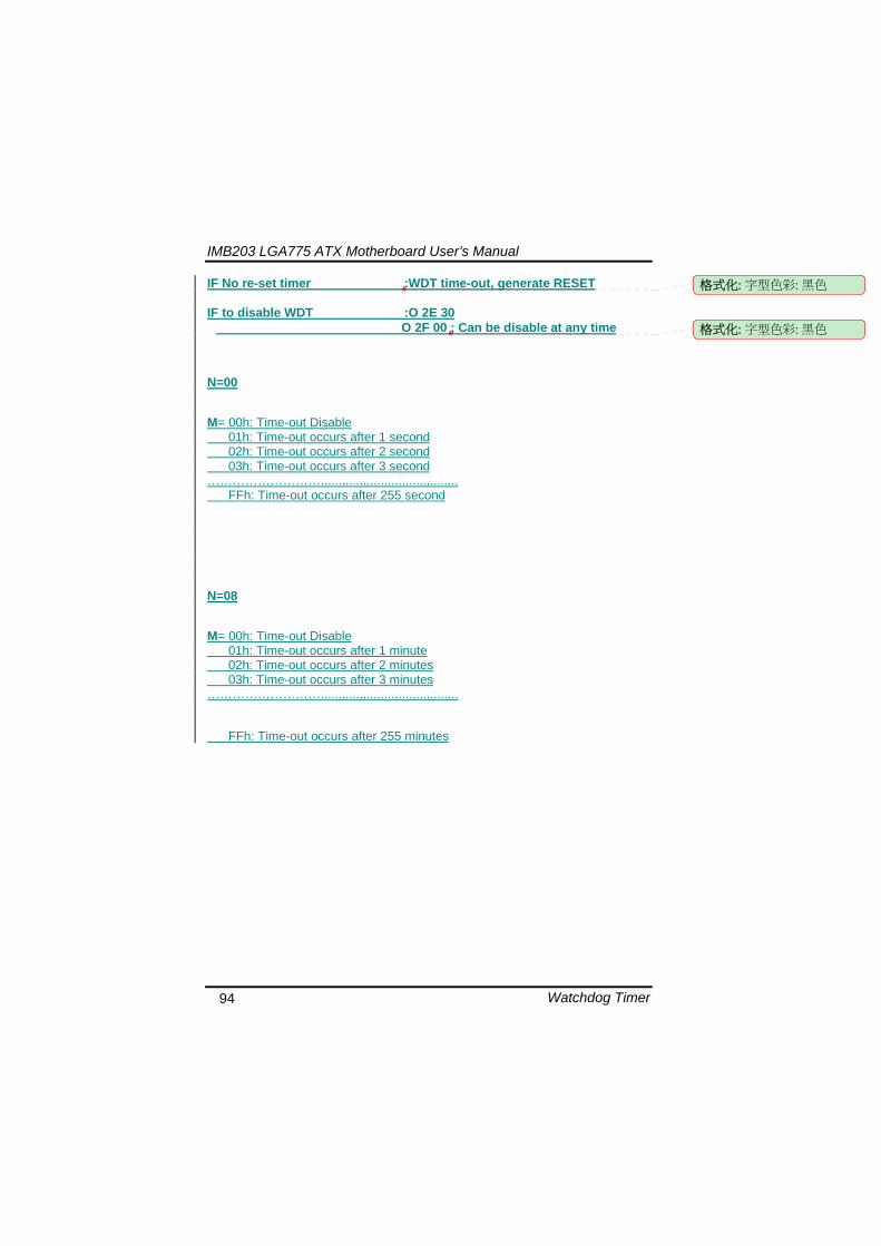
IMB203 LGA775 ATX Motherboard Userrsquos Manual
Watchdog Timer 94
IF No re-set timer WDT time-out generate RESET IF to disable WDT O 2E 30
O 2F 00 Can be disable at any time
N=00
M= 00h Time-out Disable 01h Time-out occurs after 1 second 02h Time-out occurs after 2 second 03h Time-out occurs after 3 second helliphelliphelliphelliphelliphelliphelliphelliphellip FFh Time-out occurs after 255 second
N=08
M= 00h Time-out Disable 01h Time-out occurs after 1 minute 02h Time-out occurs after 2 minutes 03h Time-out occurs after 3 minutes helliphelliphelliphelliphelliphelliphelliphelliphellip
FFh Time-out occurs after 255 minutes
格式化 字型色彩 黑色
格式化 字型色彩 黑色
IMB203 LGA775 ATX Motherboard Userrsquos Manual
PCI IRQ Routing 95
APPENDIX B PCI IRQ ROUTING
PICMG PCI IRQ Routing
Device ID Slot Int
PCI Slot 0 31 0 BCDA PCI Slot 1 30 1 CDAB PCI Slot 2 29 2 DABC PCI Slot 3 28 3 ABCD
IMB203 LGA775 ATX Motherboard Userrsquos Manual
PCI IRQ Routing 96
MEMO
IMB203 LGA775 ATX Motherboard Userrsquos Manual
Configuring SATA for RAID Function 97
APPENDIX C CONFIGURING SATA FOR RAID
FUNCTION
Configuring SATA Hard Drive(s) for RAID Function (Controller IntelregICH10DODO DH only) Please follow up the steps below to configure SATA hard drive(s) (1) Install SATA hard drive(s) in your system (2) Enter the BIOS Setup to configure SATA controller mode and boot
sequence (3) Configure RAID by the RAID BIOS (4) Install the SATA controller driver during the OS installation Before you begin the SATA configuration please prepare (a) Two SATA hard drives (to ensure optimal performance it is
recommended that you use two hard drives with identical model and capacity) If you do not want to create RAID with the SATA controller you may prepare only one hard drive
(b) An empty formatted floppy disk (c) Windows XP setup disk (1) Installing SATA hard drive(s) in your system
Connect one end of the SATA signal cable to the rear of the SATA hard drive and the other end to available SATA port(s) on the board Then connect the power connector of power supply to the hard drive
(2) Configuring SATA controller mode and boot sequence by the BIOS Setup You have to make sure whether the SATA controller is configured correctly by system BIOS Setup and set up BIOS boot sequence for the SATA hard drive(s)
IMB203 LGA775 ATX Motherboard Userrsquos Manual
Configuring SATA for RAID Function 98
(2)-1-1 Turn on your system and then press the Del button to enter BIOS Setup during running POST (Power-On Self Test) If you want to create RAID just go to the Advanced Settings menuIDE configuration select the Configure SATA1 as and press ltEntergt for more options
IMB203 LGA775 ATX Motherboard Userrsquos Manual
Configuring SATA for RAID Function 99
(2)-1-2 A list of options appears please select RAID
IMB203 LGA775 ATX Motherboard Userrsquos Manual
Configuring SATA for RAID Function 100
(2)-2 Set CDROM for First Boot Device under the Boot Settings menu to boot CD-ROM after system restarts
(2)-3 Save and exit the BIOS Setup
IMB203 LGA775 ATX Motherboard Userrsquos Manual
Configuring SATA for RAID Function 101
(3) Configuring RAID by the RAID BIOS Enter the RAID BIOS setup utility to configure a RAID array Skip this step and proceed to Section 4 if you do not want to create a RAID (3)-1 After the POST memory testing and before the operating
system booting a message Press ltCtrl-Igt to enter Configuration Utility shows up accordingly press ltCTRL+ Igt to enter the RAID BIOS setup utility
(3)-2 After you press ltCTRL+ Igt the Create RAID Volume screen will appear If you want to create a RAID array select the Create RAID Volume option in the Main Menu and press ENTER
IMB203 LGA775 ATX Motherboard Userrsquos Manual
Configuring SATA for RAID Function 102
(3)-3-1 After entering the CREATE VOLUME MENU screen you can type the disk array name with 1~16 letters (letters cannot be special characters) in the item ldquoNamerdquo
(3)-3-2 When finished press ENTER to select a RAID level There are three RAID levels RAID0 RAID1 and RAID5 amp RAID10 Select a RAID level and press ENTER
IMB203 LGA775 ATX Motherboard Userrsquos Manual
Configuring SATA for RAID Function 103
(3)-4 Set the stripe block size The KB is the standard unit of stripe block size The stripe block size can be 4KB to 128KB After the setting press ENTER for the array capacity
(3)-5 After setting all the items on the menu select Create Volume
and press ENTER to start creating the RAID array
IMB203 LGA775 ATX Motherboard Userrsquos Manual
Configuring SATA for RAID Function 104
(3)-6 When prompting the confirmation press ldquoYldquo to create this volume or ldquoNldquo to cancel the creation
After the creation is completed you can see detailed information about the RAID Array in the DISKVOLUME INFORMATION section including RAID mode disk block size disk name and disk capacity etc
IMB203 LGA775 ATX Motherboard Userrsquos Manual
Configuring SATA for RAID Function 105
Delete RAID Volume If you want to delete a RAID volume select the Delete RAID Volume option in Main Menu Press ENTER and follow on-screen instructions
Please press [ESC] to exit the RAID BIOS utility Now you can proceed to install a SATA driver controller and the operating system
IMB203 LGA775 ATX Motherboard Userrsquos Manual
Configuring SATA for RAID Function 106
(4) Making a SATA Driver Disk To install the operating system onto a serial ATA hard disk successfully you need to install the SATA controller driver during the OS installation Without the driver the hard disk may not be recognized during the Windows setup process First of all please format a blank floppy disk Secondly follow up these steps below to produce a SATA driver disk Users can insert the Driver CD and the formatted blank floppy disk in another system And then please copy all of file of the f6flpy32 folder in the Driver CD to a floppy disk Note Please copy all of file of the f6flpy64 folder if installing 64-bit
Windows Operating System
IMB203 LGA775 ATX Motherboard Userrsquos Manual
Configuring SATA for RAID Function 107
(5) Installing the SATA controller driver during the OS installation Now the SATA driver disk is ready and BIOS settings configured you can proceed to install Windows 2000XP onto your SATA hard drive using the SATA driver Here is an example for Windows XP installation (5)-1 Restart your system to boot the Windows 2000XP Setup disk
and press F6 button as soon as you see the message Press F6 if you need to install a 3rd party SCSI or RAID driver After pressing the F6 button there will be a few moments for some files being loaded before next screen appears
IMB203 LGA775 ATX Motherboard Userrsquos Manual
Configuring SATA for RAID Function 108
(5)-2 When you see the screen below insert the floppy disk containing the SATA driver and press ldquoSrdquo
(5)-3 If the Setup correctly recognizes the driver of the floppy disk
a controller menu will appear below Use the ARROW keys to select Intel(R) ICH8RICH9RICH10RDO SATA RAID Controller and press ENTER Then it will begin to load the SATA driver from the floppy disk
IMB203 LGA775 ATX Motherboard Userrsquos Manual
Configuring SATA for RAID Function 109
Note If a message on the screen saying that one or some file(s) cannot be found please check the floppy disk or copy the correct SATA driver again from the driver CD
IMB203 LGA775 ATX Motherboard Userrsquos Manual
Configuring SATA for RAID Function 110
MEMO
IMB203 LGA775 ATX Motherboard Userrsquos Manual
iAMT Settings 111
APPENDIX D iAMT SETTINGS
The Intelreg Active Management Technology (Intelreg iAMT) has decreased a major barrier to IT efficiency that uses built-in platform capabilities and popular third-party management and security applications to allow IT a better discovering healing and protection their networked computing assets In order to utilize Intel iAMT you must enter the ME BIOS (CTRL + P during system startup) change the ME BIOS password and then select ldquoIntelreg iAMTrdquo as the manageability feature
D1 Entering MEBx 1 You must go to BIOS TO start iAMT function 2 Exit from BIOS after starting iAMT and press Ctrl+P to enter MEBx Setting
It is better to press Ctrl+P before the screen popping out
格式化
IMB203 LGA775 ATX Motherboard Userrsquos Manual
iAMT Settings 112
D2 Set amp Change Password 1 You will be asked to set a password when first log in The default
password is lsquoadminrsquo
2 You will be asked to change the password before setting ME
Change Password
IMB203 LGA775 ATX Motherboard Userrsquos Manual
iAMT Settings 113
3 You must confirm your new password while revising (as Remark 1)
Remark 1 The new password must contain (example 11qqQQ) (default value)
Eight characters
One upper case
One lower case
One number
One special symbol such as $ or
( excepted)
Underline ( _ ) and space are valid characters for password but they wonrsquot make higher complexity
IMB203 LGA775 ATX Motherboard Userrsquos Manual
iAMT Settings 114
D3 Intelreg iAMT Settings 1 Select Intelreg iAMT Configuration and press ltENTERgt
2 Key in the Host Name If Intelreg iAMT set to lsquoDHCPlsquo the Host name must be identical to the operating system mechanic
IMB203 LGA775 ATX Motherboard Userrsquos Manual
iAMT Settings 115
3 Select TCPIP to get into Network interface and set it to lsquoENABLEDrsquo into DHCP Mode and set it to lsquoDISABLEDrsquo (as Remark 2) into Domain name and set the Intel Management Engine domain name such as lsquoAMTintelcomrsquo
(3-1)
(3-2)
IMB203 LGA775 ATX Motherboard Userrsquos Manual
iAMT Settings 116
Remark 2 DHCP Mode lsquoDISABLEDlsquo if DHCP Mode is disabled you can make the following settings
IP address
Subnet mask
IMB203 LGA775 ATX Motherboard Userrsquos Manual
iAMT Settings 117
Default Gateway address
Preferred DNS address
IMB203 LGA775 ATX Motherboard Userrsquos Manual
iAMT Settings 118
Alternate DNS address
Domain name
4 Exit from MEBx after completing the iAMT settings
IMB203 LGA775 ATX Motherboard Userrsquos Manual
iAMT Settings 119
D4 iAMT Web Console 1 From a web browser please type http(IP ADDRESS)16992
which connects to iAMT Web Example http1014021416992
2 To log on you will be required to type in username and password
for access to the Web
USER admin (default value)
PASS (MEBx password)
IMB203 LGA775 ATX Motherboard Userrsquos Manual
iAMT Settings 120
3 Enter the iAMT Web
4 Click Remote Control and select commands on the right side
IMB203 LGA775 ATX Motherboard Userrsquos Manual
iAMT Settings 121
5 When you have finished using the iAMT Web console close the Web browser
IMB203 LGA775 ATX Motherboard Userrsquos Manual
iAMT Settings 122
MEMO
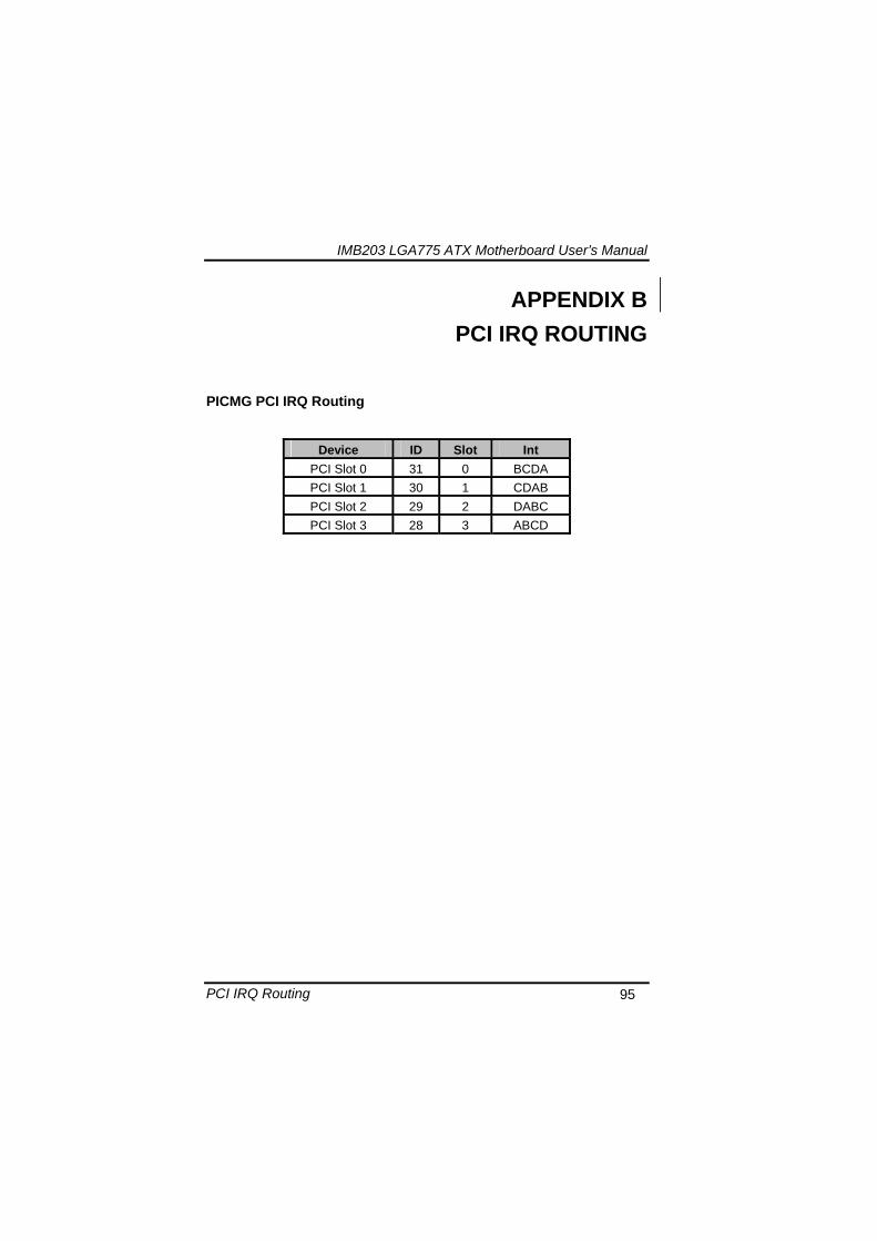
IMB203 LGA775 ATX Motherboard Userrsquos Manual
PCI IRQ Routing 96
MEMO
IMB203 LGA775 ATX Motherboard Userrsquos Manual
Configuring SATA for RAID Function 97
APPENDIX C CONFIGURING SATA FOR RAID
FUNCTION
Configuring SATA Hard Drive(s) for RAID Function (Controller IntelregICH10DODO DH only) Please follow up the steps below to configure SATA hard drive(s) (1) Install SATA hard drive(s) in your system (2) Enter the BIOS Setup to configure SATA controller mode and boot
sequence (3) Configure RAID by the RAID BIOS (4) Install the SATA controller driver during the OS installation Before you begin the SATA configuration please prepare (a) Two SATA hard drives (to ensure optimal performance it is
recommended that you use two hard drives with identical model and capacity) If you do not want to create RAID with the SATA controller you may prepare only one hard drive
(b) An empty formatted floppy disk (c) Windows XP setup disk (1) Installing SATA hard drive(s) in your system
Connect one end of the SATA signal cable to the rear of the SATA hard drive and the other end to available SATA port(s) on the board Then connect the power connector of power supply to the hard drive
(2) Configuring SATA controller mode and boot sequence by the BIOS Setup You have to make sure whether the SATA controller is configured correctly by system BIOS Setup and set up BIOS boot sequence for the SATA hard drive(s)
IMB203 LGA775 ATX Motherboard Userrsquos Manual
Configuring SATA for RAID Function 98
(2)-1-1 Turn on your system and then press the Del button to enter BIOS Setup during running POST (Power-On Self Test) If you want to create RAID just go to the Advanced Settings menuIDE configuration select the Configure SATA1 as and press ltEntergt for more options
IMB203 LGA775 ATX Motherboard Userrsquos Manual
Configuring SATA for RAID Function 99
(2)-1-2 A list of options appears please select RAID
IMB203 LGA775 ATX Motherboard Userrsquos Manual
Configuring SATA for RAID Function 100
(2)-2 Set CDROM for First Boot Device under the Boot Settings menu to boot CD-ROM after system restarts
(2)-3 Save and exit the BIOS Setup
IMB203 LGA775 ATX Motherboard Userrsquos Manual
Configuring SATA for RAID Function 101
(3) Configuring RAID by the RAID BIOS Enter the RAID BIOS setup utility to configure a RAID array Skip this step and proceed to Section 4 if you do not want to create a RAID (3)-1 After the POST memory testing and before the operating
system booting a message Press ltCtrl-Igt to enter Configuration Utility shows up accordingly press ltCTRL+ Igt to enter the RAID BIOS setup utility
(3)-2 After you press ltCTRL+ Igt the Create RAID Volume screen will appear If you want to create a RAID array select the Create RAID Volume option in the Main Menu and press ENTER
IMB203 LGA775 ATX Motherboard Userrsquos Manual
Configuring SATA for RAID Function 102
(3)-3-1 After entering the CREATE VOLUME MENU screen you can type the disk array name with 1~16 letters (letters cannot be special characters) in the item ldquoNamerdquo
(3)-3-2 When finished press ENTER to select a RAID level There are three RAID levels RAID0 RAID1 and RAID5 amp RAID10 Select a RAID level and press ENTER
IMB203 LGA775 ATX Motherboard Userrsquos Manual
Configuring SATA for RAID Function 103
(3)-4 Set the stripe block size The KB is the standard unit of stripe block size The stripe block size can be 4KB to 128KB After the setting press ENTER for the array capacity
(3)-5 After setting all the items on the menu select Create Volume
and press ENTER to start creating the RAID array
IMB203 LGA775 ATX Motherboard Userrsquos Manual
Configuring SATA for RAID Function 104
(3)-6 When prompting the confirmation press ldquoYldquo to create this volume or ldquoNldquo to cancel the creation
After the creation is completed you can see detailed information about the RAID Array in the DISKVOLUME INFORMATION section including RAID mode disk block size disk name and disk capacity etc
IMB203 LGA775 ATX Motherboard Userrsquos Manual
Configuring SATA for RAID Function 105
Delete RAID Volume If you want to delete a RAID volume select the Delete RAID Volume option in Main Menu Press ENTER and follow on-screen instructions
Please press [ESC] to exit the RAID BIOS utility Now you can proceed to install a SATA driver controller and the operating system
IMB203 LGA775 ATX Motherboard Userrsquos Manual
Configuring SATA for RAID Function 106
(4) Making a SATA Driver Disk To install the operating system onto a serial ATA hard disk successfully you need to install the SATA controller driver during the OS installation Without the driver the hard disk may not be recognized during the Windows setup process First of all please format a blank floppy disk Secondly follow up these steps below to produce a SATA driver disk Users can insert the Driver CD and the formatted blank floppy disk in another system And then please copy all of file of the f6flpy32 folder in the Driver CD to a floppy disk Note Please copy all of file of the f6flpy64 folder if installing 64-bit
Windows Operating System
IMB203 LGA775 ATX Motherboard Userrsquos Manual
Configuring SATA for RAID Function 107
(5) Installing the SATA controller driver during the OS installation Now the SATA driver disk is ready and BIOS settings configured you can proceed to install Windows 2000XP onto your SATA hard drive using the SATA driver Here is an example for Windows XP installation (5)-1 Restart your system to boot the Windows 2000XP Setup disk
and press F6 button as soon as you see the message Press F6 if you need to install a 3rd party SCSI or RAID driver After pressing the F6 button there will be a few moments for some files being loaded before next screen appears
IMB203 LGA775 ATX Motherboard Userrsquos Manual
Configuring SATA for RAID Function 108
(5)-2 When you see the screen below insert the floppy disk containing the SATA driver and press ldquoSrdquo
(5)-3 If the Setup correctly recognizes the driver of the floppy disk
a controller menu will appear below Use the ARROW keys to select Intel(R) ICH8RICH9RICH10RDO SATA RAID Controller and press ENTER Then it will begin to load the SATA driver from the floppy disk
IMB203 LGA775 ATX Motherboard Userrsquos Manual
Configuring SATA for RAID Function 109
Note If a message on the screen saying that one or some file(s) cannot be found please check the floppy disk or copy the correct SATA driver again from the driver CD
IMB203 LGA775 ATX Motherboard Userrsquos Manual
Configuring SATA for RAID Function 110
MEMO
IMB203 LGA775 ATX Motherboard Userrsquos Manual
iAMT Settings 111
APPENDIX D iAMT SETTINGS
The Intelreg Active Management Technology (Intelreg iAMT) has decreased a major barrier to IT efficiency that uses built-in platform capabilities and popular third-party management and security applications to allow IT a better discovering healing and protection their networked computing assets In order to utilize Intel iAMT you must enter the ME BIOS (CTRL + P during system startup) change the ME BIOS password and then select ldquoIntelreg iAMTrdquo as the manageability feature
D1 Entering MEBx 1 You must go to BIOS TO start iAMT function 2 Exit from BIOS after starting iAMT and press Ctrl+P to enter MEBx Setting
It is better to press Ctrl+P before the screen popping out
格式化
IMB203 LGA775 ATX Motherboard Userrsquos Manual
iAMT Settings 112
D2 Set amp Change Password 1 You will be asked to set a password when first log in The default
password is lsquoadminrsquo
2 You will be asked to change the password before setting ME
Change Password
IMB203 LGA775 ATX Motherboard Userrsquos Manual
iAMT Settings 113
3 You must confirm your new password while revising (as Remark 1)
Remark 1 The new password must contain (example 11qqQQ) (default value)
Eight characters
One upper case
One lower case
One number
One special symbol such as $ or
( excepted)
Underline ( _ ) and space are valid characters for password but they wonrsquot make higher complexity
IMB203 LGA775 ATX Motherboard Userrsquos Manual
iAMT Settings 114
D3 Intelreg iAMT Settings 1 Select Intelreg iAMT Configuration and press ltENTERgt
2 Key in the Host Name If Intelreg iAMT set to lsquoDHCPlsquo the Host name must be identical to the operating system mechanic
IMB203 LGA775 ATX Motherboard Userrsquos Manual
iAMT Settings 115
3 Select TCPIP to get into Network interface and set it to lsquoENABLEDrsquo into DHCP Mode and set it to lsquoDISABLEDrsquo (as Remark 2) into Domain name and set the Intel Management Engine domain name such as lsquoAMTintelcomrsquo
(3-1)
(3-2)
IMB203 LGA775 ATX Motherboard Userrsquos Manual
iAMT Settings 116
Remark 2 DHCP Mode lsquoDISABLEDlsquo if DHCP Mode is disabled you can make the following settings
IP address
Subnet mask
IMB203 LGA775 ATX Motherboard Userrsquos Manual
iAMT Settings 117
Default Gateway address
Preferred DNS address
IMB203 LGA775 ATX Motherboard Userrsquos Manual
iAMT Settings 118
Alternate DNS address
Domain name
4 Exit from MEBx after completing the iAMT settings
IMB203 LGA775 ATX Motherboard Userrsquos Manual
iAMT Settings 119
D4 iAMT Web Console 1 From a web browser please type http(IP ADDRESS)16992
which connects to iAMT Web Example http1014021416992
2 To log on you will be required to type in username and password
for access to the Web
USER admin (default value)
PASS (MEBx password)
IMB203 LGA775 ATX Motherboard Userrsquos Manual
iAMT Settings 120
3 Enter the iAMT Web
4 Click Remote Control and select commands on the right side
IMB203 LGA775 ATX Motherboard Userrsquos Manual
iAMT Settings 121
5 When you have finished using the iAMT Web console close the Web browser
IMB203 LGA775 ATX Motherboard Userrsquos Manual
iAMT Settings 122
MEMO
IMB203 LGA775 ATX Motherboard Userrsquos Manual
Configuring SATA for RAID Function 97
APPENDIX C CONFIGURING SATA FOR RAID
FUNCTION
Configuring SATA Hard Drive(s) for RAID Function (Controller IntelregICH10DODO DH only) Please follow up the steps below to configure SATA hard drive(s) (1) Install SATA hard drive(s) in your system (2) Enter the BIOS Setup to configure SATA controller mode and boot
sequence (3) Configure RAID by the RAID BIOS (4) Install the SATA controller driver during the OS installation Before you begin the SATA configuration please prepare (a) Two SATA hard drives (to ensure optimal performance it is
recommended that you use two hard drives with identical model and capacity) If you do not want to create RAID with the SATA controller you may prepare only one hard drive
(b) An empty formatted floppy disk (c) Windows XP setup disk (1) Installing SATA hard drive(s) in your system
Connect one end of the SATA signal cable to the rear of the SATA hard drive and the other end to available SATA port(s) on the board Then connect the power connector of power supply to the hard drive
(2) Configuring SATA controller mode and boot sequence by the BIOS Setup You have to make sure whether the SATA controller is configured correctly by system BIOS Setup and set up BIOS boot sequence for the SATA hard drive(s)
IMB203 LGA775 ATX Motherboard Userrsquos Manual
Configuring SATA for RAID Function 98
(2)-1-1 Turn on your system and then press the Del button to enter BIOS Setup during running POST (Power-On Self Test) If you want to create RAID just go to the Advanced Settings menuIDE configuration select the Configure SATA1 as and press ltEntergt for more options
IMB203 LGA775 ATX Motherboard Userrsquos Manual
Configuring SATA for RAID Function 99
(2)-1-2 A list of options appears please select RAID
IMB203 LGA775 ATX Motherboard Userrsquos Manual
Configuring SATA for RAID Function 100
(2)-2 Set CDROM for First Boot Device under the Boot Settings menu to boot CD-ROM after system restarts
(2)-3 Save and exit the BIOS Setup
IMB203 LGA775 ATX Motherboard Userrsquos Manual
Configuring SATA for RAID Function 101
(3) Configuring RAID by the RAID BIOS Enter the RAID BIOS setup utility to configure a RAID array Skip this step and proceed to Section 4 if you do not want to create a RAID (3)-1 After the POST memory testing and before the operating
system booting a message Press ltCtrl-Igt to enter Configuration Utility shows up accordingly press ltCTRL+ Igt to enter the RAID BIOS setup utility
(3)-2 After you press ltCTRL+ Igt the Create RAID Volume screen will appear If you want to create a RAID array select the Create RAID Volume option in the Main Menu and press ENTER
IMB203 LGA775 ATX Motherboard Userrsquos Manual
Configuring SATA for RAID Function 102
(3)-3-1 After entering the CREATE VOLUME MENU screen you can type the disk array name with 1~16 letters (letters cannot be special characters) in the item ldquoNamerdquo
(3)-3-2 When finished press ENTER to select a RAID level There are three RAID levels RAID0 RAID1 and RAID5 amp RAID10 Select a RAID level and press ENTER
IMB203 LGA775 ATX Motherboard Userrsquos Manual
Configuring SATA for RAID Function 103
(3)-4 Set the stripe block size The KB is the standard unit of stripe block size The stripe block size can be 4KB to 128KB After the setting press ENTER for the array capacity
(3)-5 After setting all the items on the menu select Create Volume
and press ENTER to start creating the RAID array
IMB203 LGA775 ATX Motherboard Userrsquos Manual
Configuring SATA for RAID Function 104
(3)-6 When prompting the confirmation press ldquoYldquo to create this volume or ldquoNldquo to cancel the creation
After the creation is completed you can see detailed information about the RAID Array in the DISKVOLUME INFORMATION section including RAID mode disk block size disk name and disk capacity etc
IMB203 LGA775 ATX Motherboard Userrsquos Manual
Configuring SATA for RAID Function 105
Delete RAID Volume If you want to delete a RAID volume select the Delete RAID Volume option in Main Menu Press ENTER and follow on-screen instructions
Please press [ESC] to exit the RAID BIOS utility Now you can proceed to install a SATA driver controller and the operating system
IMB203 LGA775 ATX Motherboard Userrsquos Manual
Configuring SATA for RAID Function 106
(4) Making a SATA Driver Disk To install the operating system onto a serial ATA hard disk successfully you need to install the SATA controller driver during the OS installation Without the driver the hard disk may not be recognized during the Windows setup process First of all please format a blank floppy disk Secondly follow up these steps below to produce a SATA driver disk Users can insert the Driver CD and the formatted blank floppy disk in another system And then please copy all of file of the f6flpy32 folder in the Driver CD to a floppy disk Note Please copy all of file of the f6flpy64 folder if installing 64-bit
Windows Operating System
IMB203 LGA775 ATX Motherboard Userrsquos Manual
Configuring SATA for RAID Function 107
(5) Installing the SATA controller driver during the OS installation Now the SATA driver disk is ready and BIOS settings configured you can proceed to install Windows 2000XP onto your SATA hard drive using the SATA driver Here is an example for Windows XP installation (5)-1 Restart your system to boot the Windows 2000XP Setup disk
and press F6 button as soon as you see the message Press F6 if you need to install a 3rd party SCSI or RAID driver After pressing the F6 button there will be a few moments for some files being loaded before next screen appears
IMB203 LGA775 ATX Motherboard Userrsquos Manual
Configuring SATA for RAID Function 108
(5)-2 When you see the screen below insert the floppy disk containing the SATA driver and press ldquoSrdquo
(5)-3 If the Setup correctly recognizes the driver of the floppy disk
a controller menu will appear below Use the ARROW keys to select Intel(R) ICH8RICH9RICH10RDO SATA RAID Controller and press ENTER Then it will begin to load the SATA driver from the floppy disk
IMB203 LGA775 ATX Motherboard Userrsquos Manual
Configuring SATA for RAID Function 109
Note If a message on the screen saying that one or some file(s) cannot be found please check the floppy disk or copy the correct SATA driver again from the driver CD
IMB203 LGA775 ATX Motherboard Userrsquos Manual
Configuring SATA for RAID Function 110
MEMO
IMB203 LGA775 ATX Motherboard Userrsquos Manual
iAMT Settings 111
APPENDIX D iAMT SETTINGS
The Intelreg Active Management Technology (Intelreg iAMT) has decreased a major barrier to IT efficiency that uses built-in platform capabilities and popular third-party management and security applications to allow IT a better discovering healing and protection their networked computing assets In order to utilize Intel iAMT you must enter the ME BIOS (CTRL + P during system startup) change the ME BIOS password and then select ldquoIntelreg iAMTrdquo as the manageability feature
D1 Entering MEBx 1 You must go to BIOS TO start iAMT function 2 Exit from BIOS after starting iAMT and press Ctrl+P to enter MEBx Setting
It is better to press Ctrl+P before the screen popping out
格式化
IMB203 LGA775 ATX Motherboard Userrsquos Manual
iAMT Settings 112
D2 Set amp Change Password 1 You will be asked to set a password when first log in The default
password is lsquoadminrsquo
2 You will be asked to change the password before setting ME
Change Password
IMB203 LGA775 ATX Motherboard Userrsquos Manual
iAMT Settings 113
3 You must confirm your new password while revising (as Remark 1)
Remark 1 The new password must contain (example 11qqQQ) (default value)
Eight characters
One upper case
One lower case
One number
One special symbol such as $ or
( excepted)
Underline ( _ ) and space are valid characters for password but they wonrsquot make higher complexity
IMB203 LGA775 ATX Motherboard Userrsquos Manual
iAMT Settings 114
D3 Intelreg iAMT Settings 1 Select Intelreg iAMT Configuration and press ltENTERgt
2 Key in the Host Name If Intelreg iAMT set to lsquoDHCPlsquo the Host name must be identical to the operating system mechanic
IMB203 LGA775 ATX Motherboard Userrsquos Manual
iAMT Settings 115
3 Select TCPIP to get into Network interface and set it to lsquoENABLEDrsquo into DHCP Mode and set it to lsquoDISABLEDrsquo (as Remark 2) into Domain name and set the Intel Management Engine domain name such as lsquoAMTintelcomrsquo
(3-1)
(3-2)
IMB203 LGA775 ATX Motherboard Userrsquos Manual
iAMT Settings 116
Remark 2 DHCP Mode lsquoDISABLEDlsquo if DHCP Mode is disabled you can make the following settings
IP address
Subnet mask
IMB203 LGA775 ATX Motherboard Userrsquos Manual
iAMT Settings 117
Default Gateway address
Preferred DNS address
IMB203 LGA775 ATX Motherboard Userrsquos Manual
iAMT Settings 118
Alternate DNS address
Domain name
4 Exit from MEBx after completing the iAMT settings
IMB203 LGA775 ATX Motherboard Userrsquos Manual
iAMT Settings 119
D4 iAMT Web Console 1 From a web browser please type http(IP ADDRESS)16992
which connects to iAMT Web Example http1014021416992
2 To log on you will be required to type in username and password
for access to the Web
USER admin (default value)
PASS (MEBx password)
IMB203 LGA775 ATX Motherboard Userrsquos Manual
iAMT Settings 120
3 Enter the iAMT Web
4 Click Remote Control and select commands on the right side
IMB203 LGA775 ATX Motherboard Userrsquos Manual
iAMT Settings 121
5 When you have finished using the iAMT Web console close the Web browser
IMB203 LGA775 ATX Motherboard Userrsquos Manual
iAMT Settings 122
MEMO
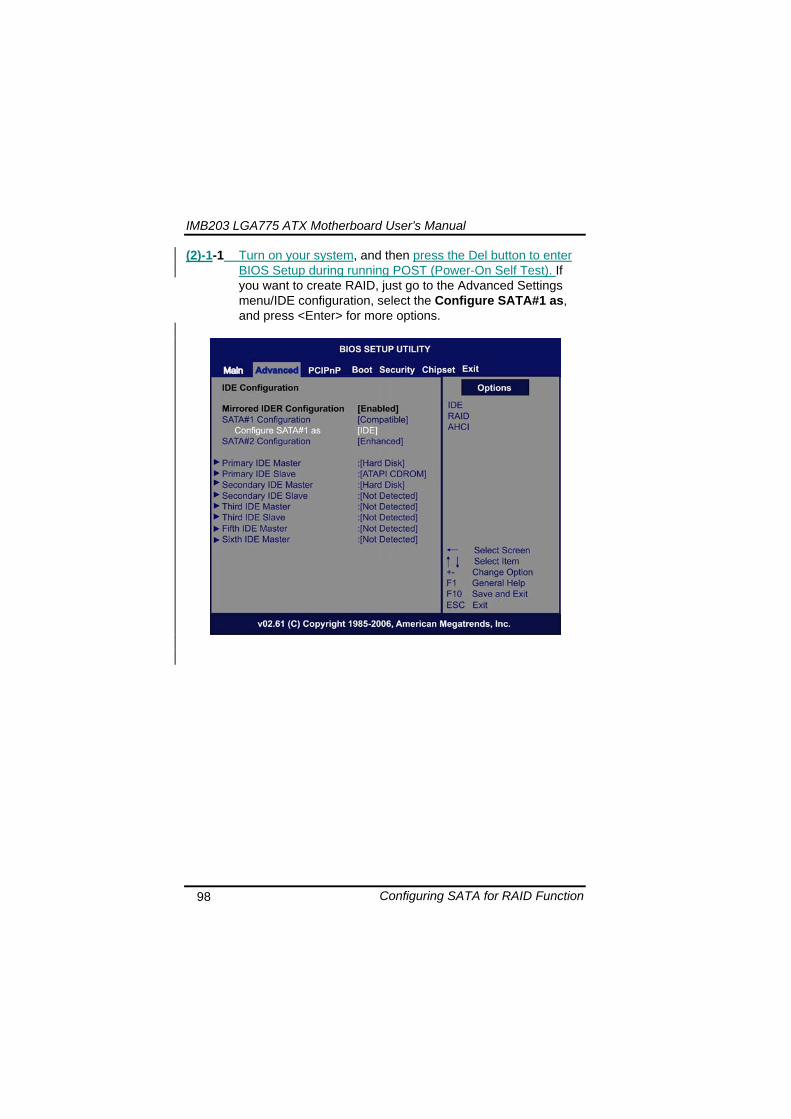
IMB203 LGA775 ATX Motherboard Userrsquos Manual
Configuring SATA for RAID Function 99
(2)-1-2 A list of options appears please select RAID
IMB203 LGA775 ATX Motherboard Userrsquos Manual
Configuring SATA for RAID Function 100
(2)-2 Set CDROM for First Boot Device under the Boot Settings menu to boot CD-ROM after system restarts
(2)-3 Save and exit the BIOS Setup
IMB203 LGA775 ATX Motherboard Userrsquos Manual
Configuring SATA for RAID Function 101
(3) Configuring RAID by the RAID BIOS Enter the RAID BIOS setup utility to configure a RAID array Skip this step and proceed to Section 4 if you do not want to create a RAID (3)-1 After the POST memory testing and before the operating
system booting a message Press ltCtrl-Igt to enter Configuration Utility shows up accordingly press ltCTRL+ Igt to enter the RAID BIOS setup utility
(3)-2 After you press ltCTRL+ Igt the Create RAID Volume screen will appear If you want to create a RAID array select the Create RAID Volume option in the Main Menu and press ENTER
IMB203 LGA775 ATX Motherboard Userrsquos Manual
Configuring SATA for RAID Function 102
(3)-3-1 After entering the CREATE VOLUME MENU screen you can type the disk array name with 1~16 letters (letters cannot be special characters) in the item ldquoNamerdquo
(3)-3-2 When finished press ENTER to select a RAID level There are three RAID levels RAID0 RAID1 and RAID5 amp RAID10 Select a RAID level and press ENTER
IMB203 LGA775 ATX Motherboard Userrsquos Manual
Configuring SATA for RAID Function 103
(3)-4 Set the stripe block size The KB is the standard unit of stripe block size The stripe block size can be 4KB to 128KB After the setting press ENTER for the array capacity
(3)-5 After setting all the items on the menu select Create Volume
and press ENTER to start creating the RAID array
IMB203 LGA775 ATX Motherboard Userrsquos Manual
Configuring SATA for RAID Function 104
(3)-6 When prompting the confirmation press ldquoYldquo to create this volume or ldquoNldquo to cancel the creation
After the creation is completed you can see detailed information about the RAID Array in the DISKVOLUME INFORMATION section including RAID mode disk block size disk name and disk capacity etc
IMB203 LGA775 ATX Motherboard Userrsquos Manual
Configuring SATA for RAID Function 105
Delete RAID Volume If you want to delete a RAID volume select the Delete RAID Volume option in Main Menu Press ENTER and follow on-screen instructions
Please press [ESC] to exit the RAID BIOS utility Now you can proceed to install a SATA driver controller and the operating system
IMB203 LGA775 ATX Motherboard Userrsquos Manual
Configuring SATA for RAID Function 106
(4) Making a SATA Driver Disk To install the operating system onto a serial ATA hard disk successfully you need to install the SATA controller driver during the OS installation Without the driver the hard disk may not be recognized during the Windows setup process First of all please format a blank floppy disk Secondly follow up these steps below to produce a SATA driver disk Users can insert the Driver CD and the formatted blank floppy disk in another system And then please copy all of file of the f6flpy32 folder in the Driver CD to a floppy disk Note Please copy all of file of the f6flpy64 folder if installing 64-bit
Windows Operating System
IMB203 LGA775 ATX Motherboard Userrsquos Manual
Configuring SATA for RAID Function 107
(5) Installing the SATA controller driver during the OS installation Now the SATA driver disk is ready and BIOS settings configured you can proceed to install Windows 2000XP onto your SATA hard drive using the SATA driver Here is an example for Windows XP installation (5)-1 Restart your system to boot the Windows 2000XP Setup disk
and press F6 button as soon as you see the message Press F6 if you need to install a 3rd party SCSI or RAID driver After pressing the F6 button there will be a few moments for some files being loaded before next screen appears
IMB203 LGA775 ATX Motherboard Userrsquos Manual
Configuring SATA for RAID Function 108
(5)-2 When you see the screen below insert the floppy disk containing the SATA driver and press ldquoSrdquo
(5)-3 If the Setup correctly recognizes the driver of the floppy disk
a controller menu will appear below Use the ARROW keys to select Intel(R) ICH8RICH9RICH10RDO SATA RAID Controller and press ENTER Then it will begin to load the SATA driver from the floppy disk
IMB203 LGA775 ATX Motherboard Userrsquos Manual
Configuring SATA for RAID Function 109
Note If a message on the screen saying that one or some file(s) cannot be found please check the floppy disk or copy the correct SATA driver again from the driver CD
IMB203 LGA775 ATX Motherboard Userrsquos Manual
Configuring SATA for RAID Function 110
MEMO
IMB203 LGA775 ATX Motherboard Userrsquos Manual
iAMT Settings 111
APPENDIX D iAMT SETTINGS
The Intelreg Active Management Technology (Intelreg iAMT) has decreased a major barrier to IT efficiency that uses built-in platform capabilities and popular third-party management and security applications to allow IT a better discovering healing and protection their networked computing assets In order to utilize Intel iAMT you must enter the ME BIOS (CTRL + P during system startup) change the ME BIOS password and then select ldquoIntelreg iAMTrdquo as the manageability feature
D1 Entering MEBx 1 You must go to BIOS TO start iAMT function 2 Exit from BIOS after starting iAMT and press Ctrl+P to enter MEBx Setting
It is better to press Ctrl+P before the screen popping out
格式化
IMB203 LGA775 ATX Motherboard Userrsquos Manual
iAMT Settings 112
D2 Set amp Change Password 1 You will be asked to set a password when first log in The default
password is lsquoadminrsquo
2 You will be asked to change the password before setting ME
Change Password
IMB203 LGA775 ATX Motherboard Userrsquos Manual
iAMT Settings 113
3 You must confirm your new password while revising (as Remark 1)
Remark 1 The new password must contain (example 11qqQQ) (default value)
Eight characters
One upper case
One lower case
One number
One special symbol such as $ or
( excepted)
Underline ( _ ) and space are valid characters for password but they wonrsquot make higher complexity
IMB203 LGA775 ATX Motherboard Userrsquos Manual
iAMT Settings 114
D3 Intelreg iAMT Settings 1 Select Intelreg iAMT Configuration and press ltENTERgt
2 Key in the Host Name If Intelreg iAMT set to lsquoDHCPlsquo the Host name must be identical to the operating system mechanic
IMB203 LGA775 ATX Motherboard Userrsquos Manual
iAMT Settings 115
3 Select TCPIP to get into Network interface and set it to lsquoENABLEDrsquo into DHCP Mode and set it to lsquoDISABLEDrsquo (as Remark 2) into Domain name and set the Intel Management Engine domain name such as lsquoAMTintelcomrsquo
(3-1)
(3-2)
IMB203 LGA775 ATX Motherboard Userrsquos Manual
iAMT Settings 116
Remark 2 DHCP Mode lsquoDISABLEDlsquo if DHCP Mode is disabled you can make the following settings
IP address
Subnet mask
IMB203 LGA775 ATX Motherboard Userrsquos Manual
iAMT Settings 117
Default Gateway address
Preferred DNS address
IMB203 LGA775 ATX Motherboard Userrsquos Manual
iAMT Settings 118
Alternate DNS address
Domain name
4 Exit from MEBx after completing the iAMT settings
IMB203 LGA775 ATX Motherboard Userrsquos Manual
iAMT Settings 119
D4 iAMT Web Console 1 From a web browser please type http(IP ADDRESS)16992
which connects to iAMT Web Example http1014021416992
2 To log on you will be required to type in username and password
for access to the Web
USER admin (default value)
PASS (MEBx password)
IMB203 LGA775 ATX Motherboard Userrsquos Manual
iAMT Settings 120
3 Enter the iAMT Web
4 Click Remote Control and select commands on the right side
IMB203 LGA775 ATX Motherboard Userrsquos Manual
iAMT Settings 121
5 When you have finished using the iAMT Web console close the Web browser
IMB203 LGA775 ATX Motherboard Userrsquos Manual
iAMT Settings 122
MEMO
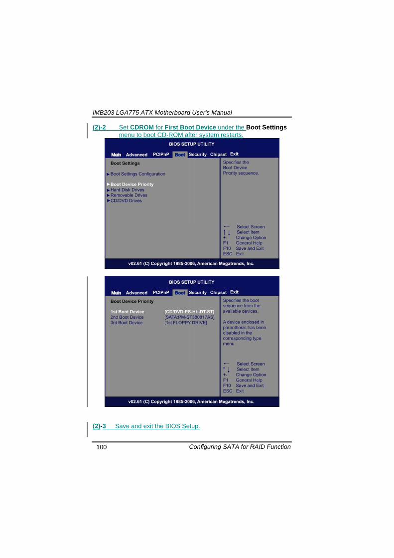
IMB203 LGA775 ATX Motherboard Userrsquos Manual
Configuring SATA for RAID Function 100
(2)-2 Set CDROM for First Boot Device under the Boot Settings menu to boot CD-ROM after system restarts
(2)-3 Save and exit the BIOS Setup
IMB203 LGA775 ATX Motherboard Userrsquos Manual
Configuring SATA for RAID Function 101
(3) Configuring RAID by the RAID BIOS Enter the RAID BIOS setup utility to configure a RAID array Skip this step and proceed to Section 4 if you do not want to create a RAID (3)-1 After the POST memory testing and before the operating
system booting a message Press ltCtrl-Igt to enter Configuration Utility shows up accordingly press ltCTRL+ Igt to enter the RAID BIOS setup utility
(3)-2 After you press ltCTRL+ Igt the Create RAID Volume screen will appear If you want to create a RAID array select the Create RAID Volume option in the Main Menu and press ENTER
IMB203 LGA775 ATX Motherboard Userrsquos Manual
Configuring SATA for RAID Function 102
(3)-3-1 After entering the CREATE VOLUME MENU screen you can type the disk array name with 1~16 letters (letters cannot be special characters) in the item ldquoNamerdquo
(3)-3-2 When finished press ENTER to select a RAID level There are three RAID levels RAID0 RAID1 and RAID5 amp RAID10 Select a RAID level and press ENTER
IMB203 LGA775 ATX Motherboard Userrsquos Manual
Configuring SATA for RAID Function 103
(3)-4 Set the stripe block size The KB is the standard unit of stripe block size The stripe block size can be 4KB to 128KB After the setting press ENTER for the array capacity
(3)-5 After setting all the items on the menu select Create Volume
and press ENTER to start creating the RAID array
IMB203 LGA775 ATX Motherboard Userrsquos Manual
Configuring SATA for RAID Function 104
(3)-6 When prompting the confirmation press ldquoYldquo to create this volume or ldquoNldquo to cancel the creation
After the creation is completed you can see detailed information about the RAID Array in the DISKVOLUME INFORMATION section including RAID mode disk block size disk name and disk capacity etc
IMB203 LGA775 ATX Motherboard Userrsquos Manual
Configuring SATA for RAID Function 105
Delete RAID Volume If you want to delete a RAID volume select the Delete RAID Volume option in Main Menu Press ENTER and follow on-screen instructions
Please press [ESC] to exit the RAID BIOS utility Now you can proceed to install a SATA driver controller and the operating system
IMB203 LGA775 ATX Motherboard Userrsquos Manual
Configuring SATA for RAID Function 106
(4) Making a SATA Driver Disk To install the operating system onto a serial ATA hard disk successfully you need to install the SATA controller driver during the OS installation Without the driver the hard disk may not be recognized during the Windows setup process First of all please format a blank floppy disk Secondly follow up these steps below to produce a SATA driver disk Users can insert the Driver CD and the formatted blank floppy disk in another system And then please copy all of file of the f6flpy32 folder in the Driver CD to a floppy disk Note Please copy all of file of the f6flpy64 folder if installing 64-bit
Windows Operating System
IMB203 LGA775 ATX Motherboard Userrsquos Manual
Configuring SATA for RAID Function 107
(5) Installing the SATA controller driver during the OS installation Now the SATA driver disk is ready and BIOS settings configured you can proceed to install Windows 2000XP onto your SATA hard drive using the SATA driver Here is an example for Windows XP installation (5)-1 Restart your system to boot the Windows 2000XP Setup disk
and press F6 button as soon as you see the message Press F6 if you need to install a 3rd party SCSI or RAID driver After pressing the F6 button there will be a few moments for some files being loaded before next screen appears
IMB203 LGA775 ATX Motherboard Userrsquos Manual
Configuring SATA for RAID Function 108
(5)-2 When you see the screen below insert the floppy disk containing the SATA driver and press ldquoSrdquo
(5)-3 If the Setup correctly recognizes the driver of the floppy disk
a controller menu will appear below Use the ARROW keys to select Intel(R) ICH8RICH9RICH10RDO SATA RAID Controller and press ENTER Then it will begin to load the SATA driver from the floppy disk
IMB203 LGA775 ATX Motherboard Userrsquos Manual
Configuring SATA for RAID Function 109
Note If a message on the screen saying that one or some file(s) cannot be found please check the floppy disk or copy the correct SATA driver again from the driver CD
IMB203 LGA775 ATX Motherboard Userrsquos Manual
Configuring SATA for RAID Function 110
MEMO
IMB203 LGA775 ATX Motherboard Userrsquos Manual
iAMT Settings 111
APPENDIX D iAMT SETTINGS
The Intelreg Active Management Technology (Intelreg iAMT) has decreased a major barrier to IT efficiency that uses built-in platform capabilities and popular third-party management and security applications to allow IT a better discovering healing and protection their networked computing assets In order to utilize Intel iAMT you must enter the ME BIOS (CTRL + P during system startup) change the ME BIOS password and then select ldquoIntelreg iAMTrdquo as the manageability feature
D1 Entering MEBx 1 You must go to BIOS TO start iAMT function 2 Exit from BIOS after starting iAMT and press Ctrl+P to enter MEBx Setting
It is better to press Ctrl+P before the screen popping out
格式化
IMB203 LGA775 ATX Motherboard Userrsquos Manual
iAMT Settings 112
D2 Set amp Change Password 1 You will be asked to set a password when first log in The default
password is lsquoadminrsquo
2 You will be asked to change the password before setting ME
Change Password
IMB203 LGA775 ATX Motherboard Userrsquos Manual
iAMT Settings 113
3 You must confirm your new password while revising (as Remark 1)
Remark 1 The new password must contain (example 11qqQQ) (default value)
Eight characters
One upper case
One lower case
One number
One special symbol such as $ or
( excepted)
Underline ( _ ) and space are valid characters for password but they wonrsquot make higher complexity
IMB203 LGA775 ATX Motherboard Userrsquos Manual
iAMT Settings 114
D3 Intelreg iAMT Settings 1 Select Intelreg iAMT Configuration and press ltENTERgt
2 Key in the Host Name If Intelreg iAMT set to lsquoDHCPlsquo the Host name must be identical to the operating system mechanic
IMB203 LGA775 ATX Motherboard Userrsquos Manual
iAMT Settings 115
3 Select TCPIP to get into Network interface and set it to lsquoENABLEDrsquo into DHCP Mode and set it to lsquoDISABLEDrsquo (as Remark 2) into Domain name and set the Intel Management Engine domain name such as lsquoAMTintelcomrsquo
(3-1)
(3-2)
IMB203 LGA775 ATX Motherboard Userrsquos Manual
iAMT Settings 116
Remark 2 DHCP Mode lsquoDISABLEDlsquo if DHCP Mode is disabled you can make the following settings
IP address
Subnet mask
IMB203 LGA775 ATX Motherboard Userrsquos Manual
iAMT Settings 117
Default Gateway address
Preferred DNS address
IMB203 LGA775 ATX Motherboard Userrsquos Manual
iAMT Settings 118
Alternate DNS address
Domain name
4 Exit from MEBx after completing the iAMT settings
IMB203 LGA775 ATX Motherboard Userrsquos Manual
iAMT Settings 119
D4 iAMT Web Console 1 From a web browser please type http(IP ADDRESS)16992
which connects to iAMT Web Example http1014021416992
2 To log on you will be required to type in username and password
for access to the Web
USER admin (default value)
PASS (MEBx password)
IMB203 LGA775 ATX Motherboard Userrsquos Manual
iAMT Settings 120
3 Enter the iAMT Web
4 Click Remote Control and select commands on the right side
IMB203 LGA775 ATX Motherboard Userrsquos Manual
iAMT Settings 121
5 When you have finished using the iAMT Web console close the Web browser
IMB203 LGA775 ATX Motherboard Userrsquos Manual
iAMT Settings 122
MEMO
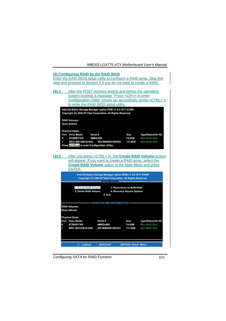
IMB203 LGA775 ATX Motherboard Userrsquos Manual
Configuring SATA for RAID Function 101
(3) Configuring RAID by the RAID BIOS Enter the RAID BIOS setup utility to configure a RAID array Skip this step and proceed to Section 4 if you do not want to create a RAID (3)-1 After the POST memory testing and before the operating
system booting a message Press ltCtrl-Igt to enter Configuration Utility shows up accordingly press ltCTRL+ Igt to enter the RAID BIOS setup utility
(3)-2 After you press ltCTRL+ Igt the Create RAID Volume screen will appear If you want to create a RAID array select the Create RAID Volume option in the Main Menu and press ENTER
IMB203 LGA775 ATX Motherboard Userrsquos Manual
Configuring SATA for RAID Function 102
(3)-3-1 After entering the CREATE VOLUME MENU screen you can type the disk array name with 1~16 letters (letters cannot be special characters) in the item ldquoNamerdquo
(3)-3-2 When finished press ENTER to select a RAID level There are three RAID levels RAID0 RAID1 and RAID5 amp RAID10 Select a RAID level and press ENTER
IMB203 LGA775 ATX Motherboard Userrsquos Manual
Configuring SATA for RAID Function 103
(3)-4 Set the stripe block size The KB is the standard unit of stripe block size The stripe block size can be 4KB to 128KB After the setting press ENTER for the array capacity
(3)-5 After setting all the items on the menu select Create Volume
and press ENTER to start creating the RAID array
IMB203 LGA775 ATX Motherboard Userrsquos Manual
Configuring SATA for RAID Function 104
(3)-6 When prompting the confirmation press ldquoYldquo to create this volume or ldquoNldquo to cancel the creation
After the creation is completed you can see detailed information about the RAID Array in the DISKVOLUME INFORMATION section including RAID mode disk block size disk name and disk capacity etc
IMB203 LGA775 ATX Motherboard Userrsquos Manual
Configuring SATA for RAID Function 105
Delete RAID Volume If you want to delete a RAID volume select the Delete RAID Volume option in Main Menu Press ENTER and follow on-screen instructions
Please press [ESC] to exit the RAID BIOS utility Now you can proceed to install a SATA driver controller and the operating system
IMB203 LGA775 ATX Motherboard Userrsquos Manual
Configuring SATA for RAID Function 106
(4) Making a SATA Driver Disk To install the operating system onto a serial ATA hard disk successfully you need to install the SATA controller driver during the OS installation Without the driver the hard disk may not be recognized during the Windows setup process First of all please format a blank floppy disk Secondly follow up these steps below to produce a SATA driver disk Users can insert the Driver CD and the formatted blank floppy disk in another system And then please copy all of file of the f6flpy32 folder in the Driver CD to a floppy disk Note Please copy all of file of the f6flpy64 folder if installing 64-bit
Windows Operating System
IMB203 LGA775 ATX Motherboard Userrsquos Manual
Configuring SATA for RAID Function 107
(5) Installing the SATA controller driver during the OS installation Now the SATA driver disk is ready and BIOS settings configured you can proceed to install Windows 2000XP onto your SATA hard drive using the SATA driver Here is an example for Windows XP installation (5)-1 Restart your system to boot the Windows 2000XP Setup disk
and press F6 button as soon as you see the message Press F6 if you need to install a 3rd party SCSI or RAID driver After pressing the F6 button there will be a few moments for some files being loaded before next screen appears
IMB203 LGA775 ATX Motherboard Userrsquos Manual
Configuring SATA for RAID Function 108
(5)-2 When you see the screen below insert the floppy disk containing the SATA driver and press ldquoSrdquo
(5)-3 If the Setup correctly recognizes the driver of the floppy disk
a controller menu will appear below Use the ARROW keys to select Intel(R) ICH8RICH9RICH10RDO SATA RAID Controller and press ENTER Then it will begin to load the SATA driver from the floppy disk
IMB203 LGA775 ATX Motherboard Userrsquos Manual
Configuring SATA for RAID Function 109
Note If a message on the screen saying that one or some file(s) cannot be found please check the floppy disk or copy the correct SATA driver again from the driver CD
IMB203 LGA775 ATX Motherboard Userrsquos Manual
Configuring SATA for RAID Function 110
MEMO
IMB203 LGA775 ATX Motherboard Userrsquos Manual
iAMT Settings 111
APPENDIX D iAMT SETTINGS
The Intelreg Active Management Technology (Intelreg iAMT) has decreased a major barrier to IT efficiency that uses built-in platform capabilities and popular third-party management and security applications to allow IT a better discovering healing and protection their networked computing assets In order to utilize Intel iAMT you must enter the ME BIOS (CTRL + P during system startup) change the ME BIOS password and then select ldquoIntelreg iAMTrdquo as the manageability feature
D1 Entering MEBx 1 You must go to BIOS TO start iAMT function 2 Exit from BIOS after starting iAMT and press Ctrl+P to enter MEBx Setting
It is better to press Ctrl+P before the screen popping out
格式化
IMB203 LGA775 ATX Motherboard Userrsquos Manual
iAMT Settings 112
D2 Set amp Change Password 1 You will be asked to set a password when first log in The default
password is lsquoadminrsquo
2 You will be asked to change the password before setting ME
Change Password
IMB203 LGA775 ATX Motherboard Userrsquos Manual
iAMT Settings 113
3 You must confirm your new password while revising (as Remark 1)
Remark 1 The new password must contain (example 11qqQQ) (default value)
Eight characters
One upper case
One lower case
One number
One special symbol such as $ or
( excepted)
Underline ( _ ) and space are valid characters for password but they wonrsquot make higher complexity
IMB203 LGA775 ATX Motherboard Userrsquos Manual
iAMT Settings 114
D3 Intelreg iAMT Settings 1 Select Intelreg iAMT Configuration and press ltENTERgt
2 Key in the Host Name If Intelreg iAMT set to lsquoDHCPlsquo the Host name must be identical to the operating system mechanic
IMB203 LGA775 ATX Motherboard Userrsquos Manual
iAMT Settings 115
3 Select TCPIP to get into Network interface and set it to lsquoENABLEDrsquo into DHCP Mode and set it to lsquoDISABLEDrsquo (as Remark 2) into Domain name and set the Intel Management Engine domain name such as lsquoAMTintelcomrsquo
(3-1)
(3-2)
IMB203 LGA775 ATX Motherboard Userrsquos Manual
iAMT Settings 116
Remark 2 DHCP Mode lsquoDISABLEDlsquo if DHCP Mode is disabled you can make the following settings
IP address
Subnet mask
IMB203 LGA775 ATX Motherboard Userrsquos Manual
iAMT Settings 117
Default Gateway address
Preferred DNS address
IMB203 LGA775 ATX Motherboard Userrsquos Manual
iAMT Settings 118
Alternate DNS address
Domain name
4 Exit from MEBx after completing the iAMT settings
IMB203 LGA775 ATX Motherboard Userrsquos Manual
iAMT Settings 119
D4 iAMT Web Console 1 From a web browser please type http(IP ADDRESS)16992
which connects to iAMT Web Example http1014021416992
2 To log on you will be required to type in username and password
for access to the Web
USER admin (default value)
PASS (MEBx password)
IMB203 LGA775 ATX Motherboard Userrsquos Manual
iAMT Settings 120
3 Enter the iAMT Web
4 Click Remote Control and select commands on the right side
IMB203 LGA775 ATX Motherboard Userrsquos Manual
iAMT Settings 121
5 When you have finished using the iAMT Web console close the Web browser
IMB203 LGA775 ATX Motherboard Userrsquos Manual
iAMT Settings 122
MEMO
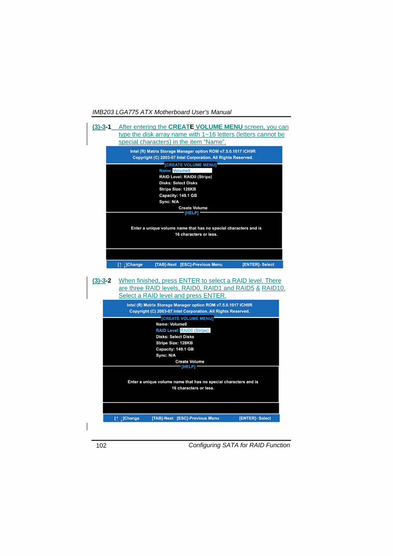
IMB203 LGA775 ATX Motherboard Userrsquos Manual
Configuring SATA for RAID Function 104
(3)-6 When prompting the confirmation press ldquoYldquo to create this volume or ldquoNldquo to cancel the creation
After the creation is completed you can see detailed information about the RAID Array in the DISKVOLUME INFORMATION section including RAID mode disk block size disk name and disk capacity etc
IMB203 LGA775 ATX Motherboard Userrsquos Manual
Configuring SATA for RAID Function 105
Delete RAID Volume If you want to delete a RAID volume select the Delete RAID Volume option in Main Menu Press ENTER and follow on-screen instructions
Please press [ESC] to exit the RAID BIOS utility Now you can proceed to install a SATA driver controller and the operating system
IMB203 LGA775 ATX Motherboard Userrsquos Manual
Configuring SATA for RAID Function 106
(4) Making a SATA Driver Disk To install the operating system onto a serial ATA hard disk successfully you need to install the SATA controller driver during the OS installation Without the driver the hard disk may not be recognized during the Windows setup process First of all please format a blank floppy disk Secondly follow up these steps below to produce a SATA driver disk Users can insert the Driver CD and the formatted blank floppy disk in another system And then please copy all of file of the f6flpy32 folder in the Driver CD to a floppy disk Note Please copy all of file of the f6flpy64 folder if installing 64-bit
Windows Operating System
IMB203 LGA775 ATX Motherboard Userrsquos Manual
Configuring SATA for RAID Function 107
(5) Installing the SATA controller driver during the OS installation Now the SATA driver disk is ready and BIOS settings configured you can proceed to install Windows 2000XP onto your SATA hard drive using the SATA driver Here is an example for Windows XP installation (5)-1 Restart your system to boot the Windows 2000XP Setup disk
and press F6 button as soon as you see the message Press F6 if you need to install a 3rd party SCSI or RAID driver After pressing the F6 button there will be a few moments for some files being loaded before next screen appears
IMB203 LGA775 ATX Motherboard Userrsquos Manual
Configuring SATA for RAID Function 108
(5)-2 When you see the screen below insert the floppy disk containing the SATA driver and press ldquoSrdquo
(5)-3 If the Setup correctly recognizes the driver of the floppy disk
a controller menu will appear below Use the ARROW keys to select Intel(R) ICH8RICH9RICH10RDO SATA RAID Controller and press ENTER Then it will begin to load the SATA driver from the floppy disk
IMB203 LGA775 ATX Motherboard Userrsquos Manual
Configuring SATA for RAID Function 109
Note If a message on the screen saying that one or some file(s) cannot be found please check the floppy disk or copy the correct SATA driver again from the driver CD
IMB203 LGA775 ATX Motherboard Userrsquos Manual
Configuring SATA for RAID Function 110
MEMO
IMB203 LGA775 ATX Motherboard Userrsquos Manual
iAMT Settings 111
APPENDIX D iAMT SETTINGS
The Intelreg Active Management Technology (Intelreg iAMT) has decreased a major barrier to IT efficiency that uses built-in platform capabilities and popular third-party management and security applications to allow IT a better discovering healing and protection their networked computing assets In order to utilize Intel iAMT you must enter the ME BIOS (CTRL + P during system startup) change the ME BIOS password and then select ldquoIntelreg iAMTrdquo as the manageability feature
D1 Entering MEBx 1 You must go to BIOS TO start iAMT function 2 Exit from BIOS after starting iAMT and press Ctrl+P to enter MEBx Setting
It is better to press Ctrl+P before the screen popping out
格式化
IMB203 LGA775 ATX Motherboard Userrsquos Manual
iAMT Settings 112
D2 Set amp Change Password 1 You will be asked to set a password when first log in The default
password is lsquoadminrsquo
2 You will be asked to change the password before setting ME
Change Password
IMB203 LGA775 ATX Motherboard Userrsquos Manual
iAMT Settings 113
3 You must confirm your new password while revising (as Remark 1)
Remark 1 The new password must contain (example 11qqQQ) (default value)
Eight characters
One upper case
One lower case
One number
One special symbol such as $ or
( excepted)
Underline ( _ ) and space are valid characters for password but they wonrsquot make higher complexity
IMB203 LGA775 ATX Motherboard Userrsquos Manual
iAMT Settings 114
D3 Intelreg iAMT Settings 1 Select Intelreg iAMT Configuration and press ltENTERgt
2 Key in the Host Name If Intelreg iAMT set to lsquoDHCPlsquo the Host name must be identical to the operating system mechanic
IMB203 LGA775 ATX Motherboard Userrsquos Manual
iAMT Settings 115
3 Select TCPIP to get into Network interface and set it to lsquoENABLEDrsquo into DHCP Mode and set it to lsquoDISABLEDrsquo (as Remark 2) into Domain name and set the Intel Management Engine domain name such as lsquoAMTintelcomrsquo
(3-1)
(3-2)
IMB203 LGA775 ATX Motherboard Userrsquos Manual
iAMT Settings 116
Remark 2 DHCP Mode lsquoDISABLEDlsquo if DHCP Mode is disabled you can make the following settings
IP address
Subnet mask
IMB203 LGA775 ATX Motherboard Userrsquos Manual
iAMT Settings 117
Default Gateway address
Preferred DNS address
IMB203 LGA775 ATX Motherboard Userrsquos Manual
iAMT Settings 118
Alternate DNS address
Domain name
4 Exit from MEBx after completing the iAMT settings
IMB203 LGA775 ATX Motherboard Userrsquos Manual
iAMT Settings 119
D4 iAMT Web Console 1 From a web browser please type http(IP ADDRESS)16992
which connects to iAMT Web Example http1014021416992
2 To log on you will be required to type in username and password
for access to the Web
USER admin (default value)
PASS (MEBx password)
IMB203 LGA775 ATX Motherboard Userrsquos Manual
iAMT Settings 120
3 Enter the iAMT Web
4 Click Remote Control and select commands on the right side
IMB203 LGA775 ATX Motherboard Userrsquos Manual
iAMT Settings 121
5 When you have finished using the iAMT Web console close the Web browser
IMB203 LGA775 ATX Motherboard Userrsquos Manual
iAMT Settings 122
MEMO
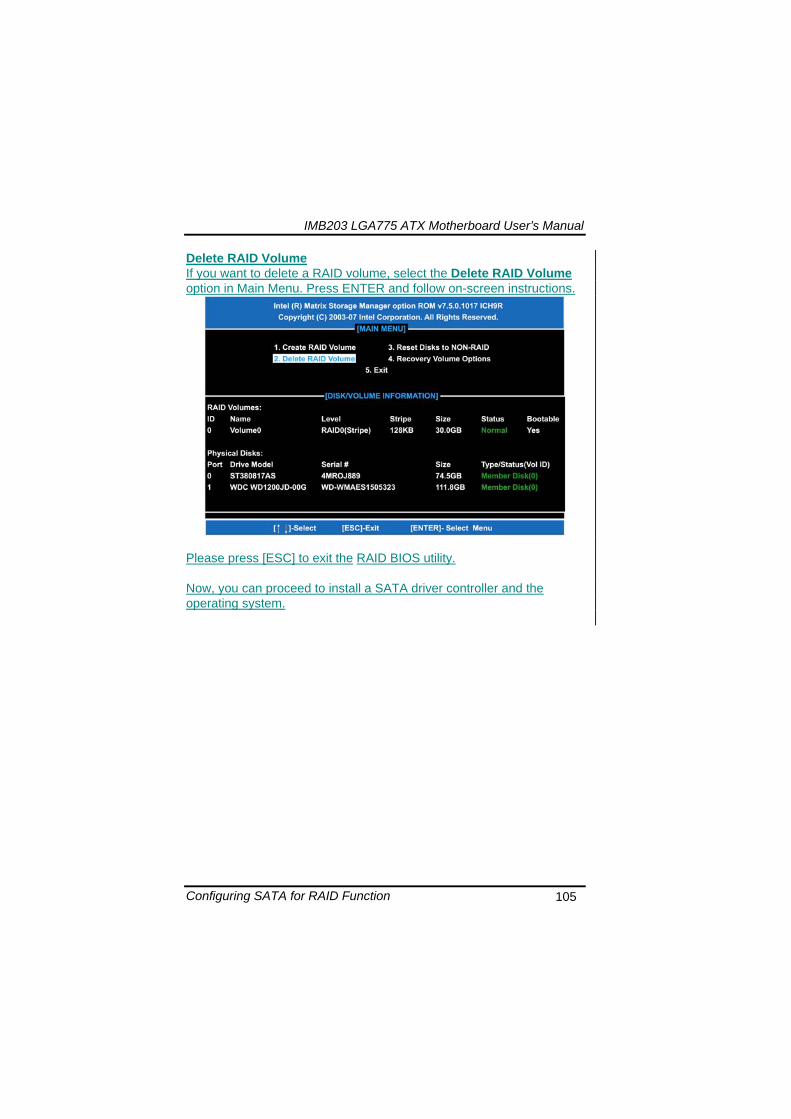
IMB203 LGA775 ATX Motherboard Userrsquos Manual
Configuring SATA for RAID Function 110
MEMO
IMB203 LGA775 ATX Motherboard Userrsquos Manual
iAMT Settings 111
APPENDIX D iAMT SETTINGS
The Intelreg Active Management Technology (Intelreg iAMT) has decreased a major barrier to IT efficiency that uses built-in platform capabilities and popular third-party management and security applications to allow IT a better discovering healing and protection their networked computing assets In order to utilize Intel iAMT you must enter the ME BIOS (CTRL + P during system startup) change the ME BIOS password and then select ldquoIntelreg iAMTrdquo as the manageability feature
D1 Entering MEBx 1 You must go to BIOS TO start iAMT function 2 Exit from BIOS after starting iAMT and press Ctrl+P to enter MEBx Setting
It is better to press Ctrl+P before the screen popping out
格式化
IMB203 LGA775 ATX Motherboard Userrsquos Manual
iAMT Settings 112
D2 Set amp Change Password 1 You will be asked to set a password when first log in The default
password is lsquoadminrsquo
2 You will be asked to change the password before setting ME
Change Password
IMB203 LGA775 ATX Motherboard Userrsquos Manual
iAMT Settings 113
3 You must confirm your new password while revising (as Remark 1)
Remark 1 The new password must contain (example 11qqQQ) (default value)
Eight characters
One upper case
One lower case
One number
One special symbol such as $ or
( excepted)
Underline ( _ ) and space are valid characters for password but they wonrsquot make higher complexity
IMB203 LGA775 ATX Motherboard Userrsquos Manual
iAMT Settings 114
D3 Intelreg iAMT Settings 1 Select Intelreg iAMT Configuration and press ltENTERgt
2 Key in the Host Name If Intelreg iAMT set to lsquoDHCPlsquo the Host name must be identical to the operating system mechanic
IMB203 LGA775 ATX Motherboard Userrsquos Manual
iAMT Settings 115
3 Select TCPIP to get into Network interface and set it to lsquoENABLEDrsquo into DHCP Mode and set it to lsquoDISABLEDrsquo (as Remark 2) into Domain name and set the Intel Management Engine domain name such as lsquoAMTintelcomrsquo
(3-1)
(3-2)
IMB203 LGA775 ATX Motherboard Userrsquos Manual
iAMT Settings 116
Remark 2 DHCP Mode lsquoDISABLEDlsquo if DHCP Mode is disabled you can make the following settings
IP address
Subnet mask
IMB203 LGA775 ATX Motherboard Userrsquos Manual
iAMT Settings 117
Default Gateway address
Preferred DNS address
IMB203 LGA775 ATX Motherboard Userrsquos Manual
iAMT Settings 118
Alternate DNS address
Domain name
4 Exit from MEBx after completing the iAMT settings
IMB203 LGA775 ATX Motherboard Userrsquos Manual
iAMT Settings 119
D4 iAMT Web Console 1 From a web browser please type http(IP ADDRESS)16992
which connects to iAMT Web Example http1014021416992
2 To log on you will be required to type in username and password
for access to the Web
USER admin (default value)
PASS (MEBx password)
IMB203 LGA775 ATX Motherboard Userrsquos Manual
iAMT Settings 120
3 Enter the iAMT Web
4 Click Remote Control and select commands on the right side
IMB203 LGA775 ATX Motherboard Userrsquos Manual
iAMT Settings 121
5 When you have finished using the iAMT Web console close the Web browser
IMB203 LGA775 ATX Motherboard Userrsquos Manual
iAMT Settings 122
MEMO
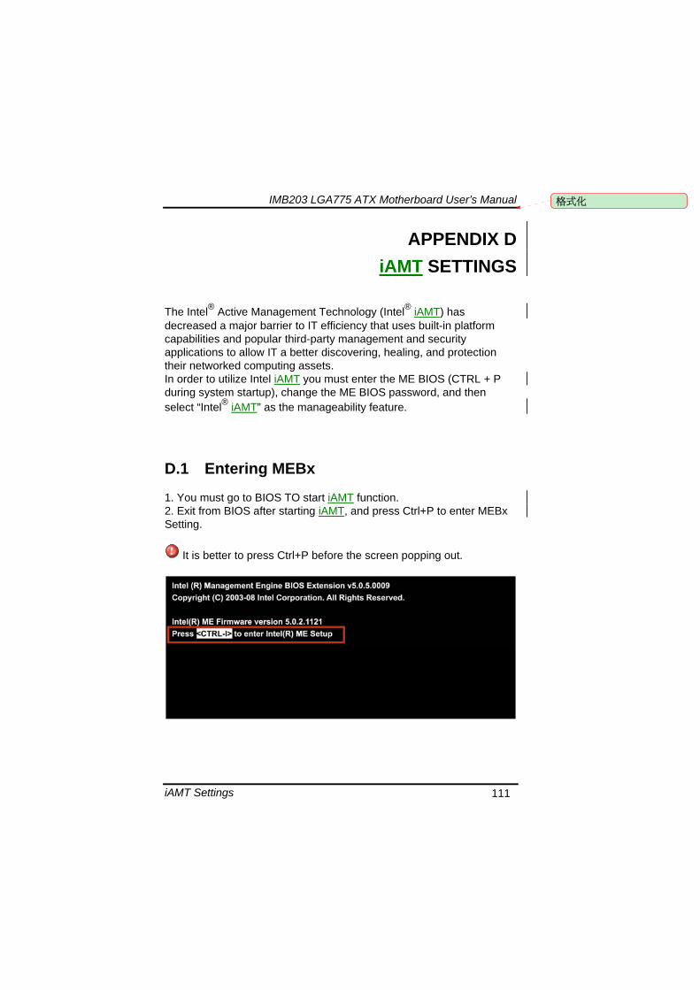
IMB203 LGA775 ATX Motherboard Userrsquos Manual
iAMT Settings 111
APPENDIX D iAMT SETTINGS
The Intelreg Active Management Technology (Intelreg iAMT) has decreased a major barrier to IT efficiency that uses built-in platform capabilities and popular third-party management and security applications to allow IT a better discovering healing and protection their networked computing assets In order to utilize Intel iAMT you must enter the ME BIOS (CTRL + P during system startup) change the ME BIOS password and then select ldquoIntelreg iAMTrdquo as the manageability feature
D1 Entering MEBx 1 You must go to BIOS TO start iAMT function 2 Exit from BIOS after starting iAMT and press Ctrl+P to enter MEBx Setting
It is better to press Ctrl+P before the screen popping out
格式化
IMB203 LGA775 ATX Motherboard Userrsquos Manual
iAMT Settings 112
D2 Set amp Change Password 1 You will be asked to set a password when first log in The default
password is lsquoadminrsquo
2 You will be asked to change the password before setting ME
Change Password
IMB203 LGA775 ATX Motherboard Userrsquos Manual
iAMT Settings 113
3 You must confirm your new password while revising (as Remark 1)
Remark 1 The new password must contain (example 11qqQQ) (default value)
Eight characters
One upper case
One lower case
One number
One special symbol such as $ or
( excepted)
Underline ( _ ) and space are valid characters for password but they wonrsquot make higher complexity
IMB203 LGA775 ATX Motherboard Userrsquos Manual
iAMT Settings 114
D3 Intelreg iAMT Settings 1 Select Intelreg iAMT Configuration and press ltENTERgt
2 Key in the Host Name If Intelreg iAMT set to lsquoDHCPlsquo the Host name must be identical to the operating system mechanic
IMB203 LGA775 ATX Motherboard Userrsquos Manual
iAMT Settings 115
3 Select TCPIP to get into Network interface and set it to lsquoENABLEDrsquo into DHCP Mode and set it to lsquoDISABLEDrsquo (as Remark 2) into Domain name and set the Intel Management Engine domain name such as lsquoAMTintelcomrsquo
(3-1)
(3-2)
IMB203 LGA775 ATX Motherboard Userrsquos Manual
iAMT Settings 116
Remark 2 DHCP Mode lsquoDISABLEDlsquo if DHCP Mode is disabled you can make the following settings
IP address
Subnet mask
IMB203 LGA775 ATX Motherboard Userrsquos Manual
iAMT Settings 117
Default Gateway address
Preferred DNS address
IMB203 LGA775 ATX Motherboard Userrsquos Manual
iAMT Settings 118
Alternate DNS address
Domain name
4 Exit from MEBx after completing the iAMT settings
IMB203 LGA775 ATX Motherboard Userrsquos Manual
iAMT Settings 119
D4 iAMT Web Console 1 From a web browser please type http(IP ADDRESS)16992
which connects to iAMT Web Example http1014021416992
2 To log on you will be required to type in username and password
for access to the Web
USER admin (default value)
PASS (MEBx password)
IMB203 LGA775 ATX Motherboard Userrsquos Manual
iAMT Settings 120
3 Enter the iAMT Web
4 Click Remote Control and select commands on the right side
IMB203 LGA775 ATX Motherboard Userrsquos Manual
iAMT Settings 121
5 When you have finished using the iAMT Web console close the Web browser
IMB203 LGA775 ATX Motherboard Userrsquos Manual
iAMT Settings 122
MEMO
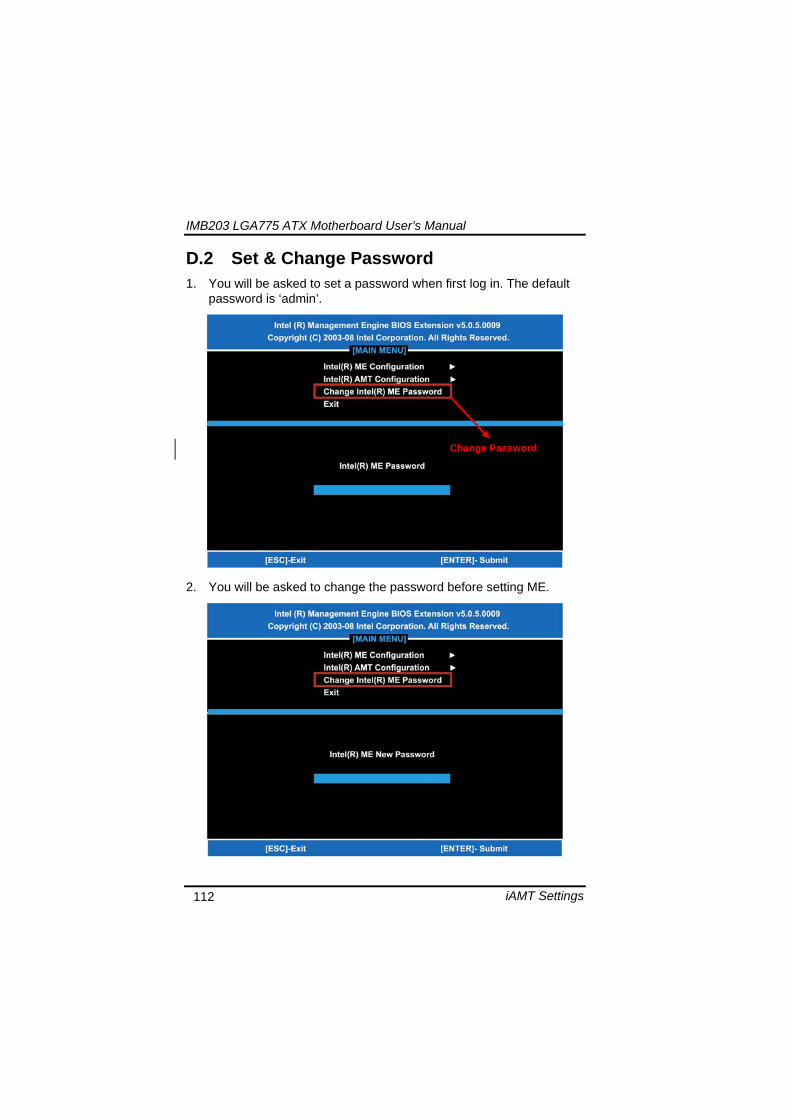
IMB203 LGA775 ATX Motherboard Userrsquos Manual
iAMT Settings 113
3 You must confirm your new password while revising (as Remark 1)
Remark 1 The new password must contain (example 11qqQQ) (default value)
Eight characters
One upper case
One lower case
One number
One special symbol such as $ or
( excepted)
Underline ( _ ) and space are valid characters for password but they wonrsquot make higher complexity
IMB203 LGA775 ATX Motherboard Userrsquos Manual
iAMT Settings 114
D3 Intelreg iAMT Settings 1 Select Intelreg iAMT Configuration and press ltENTERgt
2 Key in the Host Name If Intelreg iAMT set to lsquoDHCPlsquo the Host name must be identical to the operating system mechanic
IMB203 LGA775 ATX Motherboard Userrsquos Manual
iAMT Settings 115
3 Select TCPIP to get into Network interface and set it to lsquoENABLEDrsquo into DHCP Mode and set it to lsquoDISABLEDrsquo (as Remark 2) into Domain name and set the Intel Management Engine domain name such as lsquoAMTintelcomrsquo
(3-1)
(3-2)
IMB203 LGA775 ATX Motherboard Userrsquos Manual
iAMT Settings 116
Remark 2 DHCP Mode lsquoDISABLEDlsquo if DHCP Mode is disabled you can make the following settings
IP address
Subnet mask
IMB203 LGA775 ATX Motherboard Userrsquos Manual
iAMT Settings 117
Default Gateway address
Preferred DNS address
IMB203 LGA775 ATX Motherboard Userrsquos Manual
iAMT Settings 118
Alternate DNS address
Domain name
4 Exit from MEBx after completing the iAMT settings
IMB203 LGA775 ATX Motherboard Userrsquos Manual
iAMT Settings 119
D4 iAMT Web Console 1 From a web browser please type http(IP ADDRESS)16992
which connects to iAMT Web Example http1014021416992
2 To log on you will be required to type in username and password
for access to the Web
USER admin (default value)
PASS (MEBx password)
IMB203 LGA775 ATX Motherboard Userrsquos Manual
iAMT Settings 120
3 Enter the iAMT Web
4 Click Remote Control and select commands on the right side
IMB203 LGA775 ATX Motherboard Userrsquos Manual
iAMT Settings 121
5 When you have finished using the iAMT Web console close the Web browser
IMB203 LGA775 ATX Motherboard Userrsquos Manual
iAMT Settings 122
MEMO
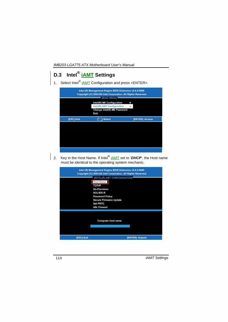
IMB203 LGA775 ATX Motherboard Userrsquos Manual
iAMT Settings 114
D3 Intelreg iAMT Settings 1 Select Intelreg iAMT Configuration and press ltENTERgt
2 Key in the Host Name If Intelreg iAMT set to lsquoDHCPlsquo the Host name must be identical to the operating system mechanic
IMB203 LGA775 ATX Motherboard Userrsquos Manual
iAMT Settings 115
3 Select TCPIP to get into Network interface and set it to lsquoENABLEDrsquo into DHCP Mode and set it to lsquoDISABLEDrsquo (as Remark 2) into Domain name and set the Intel Management Engine domain name such as lsquoAMTintelcomrsquo
(3-1)
(3-2)
IMB203 LGA775 ATX Motherboard Userrsquos Manual
iAMT Settings 116
Remark 2 DHCP Mode lsquoDISABLEDlsquo if DHCP Mode is disabled you can make the following settings
IP address
Subnet mask
IMB203 LGA775 ATX Motherboard Userrsquos Manual
iAMT Settings 117
Default Gateway address
Preferred DNS address
IMB203 LGA775 ATX Motherboard Userrsquos Manual
iAMT Settings 118
Alternate DNS address
Domain name
4 Exit from MEBx after completing the iAMT settings
IMB203 LGA775 ATX Motherboard Userrsquos Manual
iAMT Settings 119
D4 iAMT Web Console 1 From a web browser please type http(IP ADDRESS)16992
which connects to iAMT Web Example http1014021416992
2 To log on you will be required to type in username and password
for access to the Web
USER admin (default value)
PASS (MEBx password)
IMB203 LGA775 ATX Motherboard Userrsquos Manual
iAMT Settings 120
3 Enter the iAMT Web
4 Click Remote Control and select commands on the right side
IMB203 LGA775 ATX Motherboard Userrsquos Manual
iAMT Settings 121
5 When you have finished using the iAMT Web console close the Web browser
IMB203 LGA775 ATX Motherboard Userrsquos Manual
iAMT Settings 122
MEMO
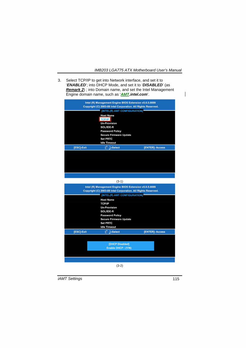
IMB203 LGA775 ATX Motherboard Userrsquos Manual
iAMT Settings 115
3 Select TCPIP to get into Network interface and set it to lsquoENABLEDrsquo into DHCP Mode and set it to lsquoDISABLEDrsquo (as Remark 2) into Domain name and set the Intel Management Engine domain name such as lsquoAMTintelcomrsquo
(3-1)
(3-2)
IMB203 LGA775 ATX Motherboard Userrsquos Manual
iAMT Settings 116
Remark 2 DHCP Mode lsquoDISABLEDlsquo if DHCP Mode is disabled you can make the following settings
IP address
Subnet mask
IMB203 LGA775 ATX Motherboard Userrsquos Manual
iAMT Settings 117
Default Gateway address
Preferred DNS address
IMB203 LGA775 ATX Motherboard Userrsquos Manual
iAMT Settings 118
Alternate DNS address
Domain name
4 Exit from MEBx after completing the iAMT settings
IMB203 LGA775 ATX Motherboard Userrsquos Manual
iAMT Settings 119
D4 iAMT Web Console 1 From a web browser please type http(IP ADDRESS)16992
which connects to iAMT Web Example http1014021416992
2 To log on you will be required to type in username and password
for access to the Web
USER admin (default value)
PASS (MEBx password)
IMB203 LGA775 ATX Motherboard Userrsquos Manual
iAMT Settings 120
3 Enter the iAMT Web
4 Click Remote Control and select commands on the right side
IMB203 LGA775 ATX Motherboard Userrsquos Manual
iAMT Settings 121
5 When you have finished using the iAMT Web console close the Web browser
IMB203 LGA775 ATX Motherboard Userrsquos Manual
iAMT Settings 122
MEMO
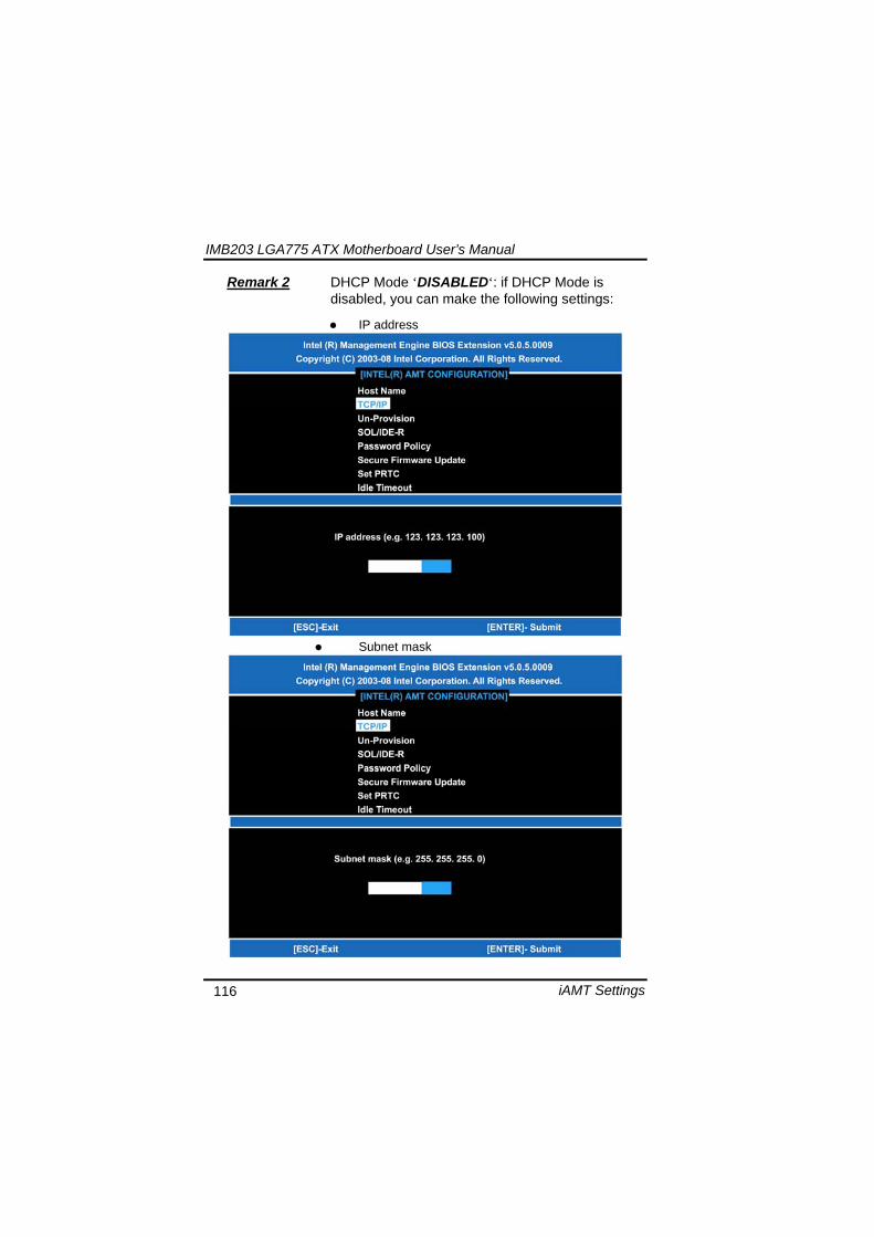
IMB203 LGA775 ATX Motherboard Userrsquos Manual
iAMT Settings 119
D4 iAMT Web Console 1 From a web browser please type http(IP ADDRESS)16992
which connects to iAMT Web Example http1014021416992
2 To log on you will be required to type in username and password
for access to the Web
USER admin (default value)
PASS (MEBx password)
IMB203 LGA775 ATX Motherboard Userrsquos Manual
iAMT Settings 120
3 Enter the iAMT Web
4 Click Remote Control and select commands on the right side
IMB203 LGA775 ATX Motherboard Userrsquos Manual
iAMT Settings 121
5 When you have finished using the iAMT Web console close the Web browser
IMB203 LGA775 ATX Motherboard Userrsquos Manual
iAMT Settings 122
MEMO
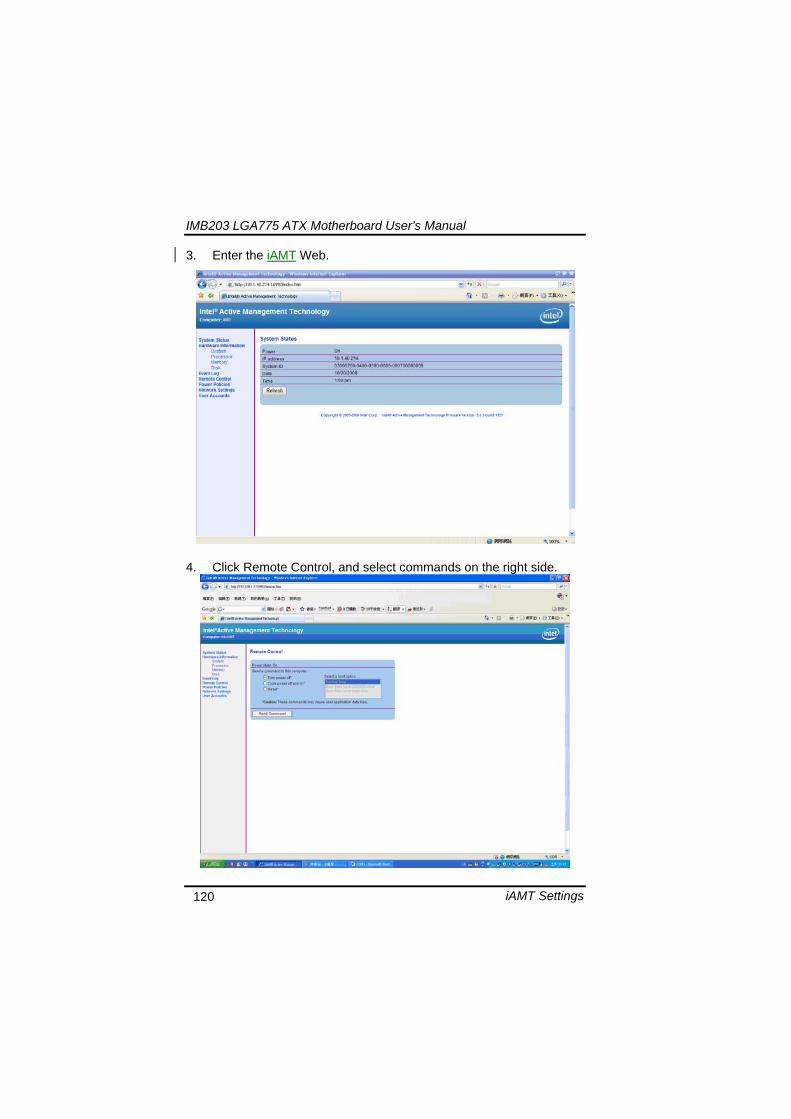
IMB203 LGA775 ATX Motherboard Userrsquos Manual
iAMT Settings 121
5 When you have finished using the iAMT Web console close the Web browser
IMB203 LGA775 ATX Motherboard Userrsquos Manual
iAMT Settings 122
MEMO

IMB203 LGA775 ATX Motherboard Userrsquos Manual
iAMT Settings 122
MEMO