imcv fiberlinx ii a0
TRANSCRIPT
iMcV-FiberLinX-II
Operation Manual

FCC Radio Frequency Interference Statement
This equipment has been tested and found to comply with the limits for a Class B computing device, pursuant to Part 15 of the FCC Rules.
These limits are designed to provide reasonable protection against harmful interference when the equipment is operated in a commercial
environment. This equipment generates uses and can radiate radio frequency energy and, if not installed and used in accordance with the
instruction manual, may cause harmful interference to radio communications. Operation of this equipment in a residential area is likely to
cause harmful interference in which the user will be required to correct the interference at his own expense.
Any changes or modifications not expressly approved by the manufacturer could void the user’s authority to operate the equipment.
The use of non-shielded I/O cables may not guarantee compliance with FCC RFI limits. This digital apparatus does not exceed the Class B
limits for radio noise emission from digital apparatus set out in the Radio Interference Regulation of the Canadian Department of
Communications.
Le présent appareil numérique n’émet pas de bruits radioélectriques dépassant les limites applicables aux appareils numériques de classe B
prescrites dans le Règlement sur le brouillage radioélectrique publié par le ministère des Communications du Canada.
Warranty
IMC Networks warrants to the original end-user purchaser that this product, EXCLUSIVE OF SOFTWARE, shall be free from defects in materials and workmanship under normal and proper use in accordance with IMC Networks' instructions and directions for a period of six (6) years after the original date of purchase. This warranty is subject to the limitations set forth below.
At its option, IMC Networks will repair or replace at no charge the product which proves to be defective within such warranty period. This limited warranty shall not apply if the IMC Networks product has been damaged by unreasonable use, accident, negligence, service or modification by anyone other than an authorized IMC Networks Service Technician or by any other causes unrelated to defective materials or workmanship. Any replaced or repaired products or parts carry a ninety (90) day warranty or the remainder of the initial warranty period, whichever is longer.
To receive in-warranty service, the defective product must be received at IMC Networks no later than the end of the warranty period. The product must be accompanied by proof of purchase, satisfactory to IMC Networks, denoting product serial number and purchase date, a written description of the defect and a Return Merchandise Authorization (RMA) number issued by IMC Networks. No products will be accepted by IMC Networks which do not have an RMA number. For an RMA number, contact IMC Networks at PHONE: (800) 624-1070 (in the U.S and Canada) or (949) 465-3000 or FAX: (949) 465-3020. The end-user shall return the defective product to IMC Networks, freight, customs and handling charges prepaid. End-user agrees to accept all liability for loss of or damages to the returned product during shipment. IMC Networks shall repair or replace the returned product, at its option, and return the repaired or new product to the end-user, freight prepaid, via method to be determined by IMC Networks. IMC Networks shall not be liable for any costs of procurement of substitute goods, loss of profits, or any incidental, consequential, and/or special damages of any kind resulting from a breach of any applicable express or implied warranty, breach of any obligation arising from breach of warranty, or otherwise with respect to the manufacture and sale of any IMC Networks product, whether or not IMC Networks has been advised of the possibility of such loss or damage.
EXCEPT FOR THE EXPRESS WARRANTY SET FORTH ABOVE, IMC NETWORKS MAKES NO OTHER WARRANTIES, WHETHER EXPRESS OR IMPLIED, WITH RESPECT TO THIS IMC NETWORKS PRODUCT, INCLUDING WITHOUT LIMITATION ANY SOFTWARE ASSOCIATED OR INCLUDED. IMC NETWORKS SHALL DISREGARD AND NOT BE BOUND BY ANY REPRESENTATIONS OR WARRANTIES MADE BY ANY OTHER PERSON, INCLUDING EMPLOYEES, DISTRIBUTORS, RESELLERS OR DEALERS OF IMC NETWORKS, WHICH ARE
INCONSISTENT WITH THE WARRANTY SET FORTH ABOVE. ALL IMPLIED WARRANTIES INCLUDING THOSE OF MERCHANTABILITY AND FITNESS FOR A PARTICULAR PURPOSE ARE HEREBY LIMITED TO THE DURATION OF THE EXPRESS WARRANTY STATED ABOVE.
Every reasonable effort has been made to ensure that IMC Networks product manuals and promotional materials accurately describe IMC Networks product specifications and capabilities at the time of publication. However, because of ongoing improvements and updating of IMC Networks products, IMC Networks cannot guarantee the accuracy of printed materials after the date of publication and disclaims liability for changes, errors or omissions.
ii
Table of Contents
FCC Radio Frequency Interference Statement ------------------------------------------------ ii Warranty---------------------------------------------------------------------------------------------- ii I - About the iMcV-FiberLinX-II-------------------------------------------------------------------5
Port Interfaces---------------------------------------------------------------------------------6 Default Username/Password ---------------------------------------------------------------7
II - LED Operation ----------------------------------------------------------------------------------9 Port LEDs---------------------------------------------------------------------------------------9 Diagnostic LEDs-------------------------------------------------------------------------------9
III - Hardware Configuration -------------------------------------------------------------------- 10 IV - Installation Instructions --------------------------------------------------------------------- 12 V - Software Configuration ---------------------------------------------------------------------- 12
Autonegotiation----------------------------------------------------------------------------- 13 Forcing the Speed and Duplex Mode -------------------------------------------------- 13 Selective Advertising ----------------------------------------------------------------------- 13 Bandwidth Control ------------------------------------------------------------------------- 13 FX LinkLoss ---------------------------------------------------------------------------------- 14 TX LinkLoss ---------------------------------------------------------------------------------- 14 FiberAlert------------------------------------------------------------------------------------- 14 Using LinkLoss and FiberAlert------------------------------------------------------------ 14
Loopback Testing on Remote or Standalone --------------------------------------------- 16 Address Swap ------------------------------------------------------------------------------- 16 Address Swap and Clear Multicast Bit -------------------------------------------------- 16 No Learning on OPTICS and DATA Ports --------------------------------------------- 16
VI - Using Telnet ---------------------------------------------------------------------------------- 17 Serial Port (EXT MGMT) ------------------------------------------------------------------- 17
Basic Device Configuration ------------------------------------------------------------------ 18 Saved and Current Values ---------------------------------------------------------------- 18 Command List------------------------------------------------------------------------------- 18 (I) - Assigning IP Information ------------------------------------------------------------- 19 (P) - Password Protection/Changing Password ---------------------------------------- 19 (T) - Assigning SNMP Trap Destinations------------------------------------------------ 20 (K) - Removing All SNMP Trap Destinations------------------------------------------- 20 (C) - Creating SNMP Community Strings----------------------------------------------- 20 (U) - Deleting All SNMP Community Strings ------------------------------------------ 21 (E) - Ending Your Session ------------------------------------------------------------------ 21 (REBOOT) – Reboot Device-------------------------------------------------------------- 21 (D) – Enabling DHCP ---------------------------------------------------------------------- 21 Transparent Mode-------------------------------------------------------------------------- 25 Transparent Mode Setup Screen -------------------------------------------------------- 25 Transparent Mode Setup------------------------------------------------------------------ 26 Transparent with Extra-Tagging ---------------------------------------------------------- 26
iii
iv
Transparent with VLAN Tag on EXT MGMT Port------------------------------------- 27 Default Mode ------------------------------------------------------------------------------- 28 Port VLAN on OPTICS (or UPLINK) port ---------------------------------------------- 28 Port VLAN on DATA Port ----------------------------------------------------------------- 29 Management VLAN and EXT MGMT Tag---------------------------------------------- 29 Port VLAN Filter ---------------------------------------------------------------------------- 30
VII - Application Overview ---------------------------------------------------------------------- 33 VIII - Application Examples---------------------------------------------------------------------- 34
Transparent with Tagged Management---------------------------------------------------- 36 Transparent with Tagged Management---------------------------------------------------- 37 Transparent with Extra Tagging (Q-in-Q)-------------------------------------------------- 39 Port VLAN--------------------------------------------------------------------------------------- 42
VLAN on DATA Port - Configuration --------------------------------------------------- 42 VLAN on OPTIC Port - Configuration -------------------------------------------------- 44
IX - Troubleshooting ------------------------------------------------------------------------------ 49 Troubleshooting LinkLoss/FiberAlert/Link Fault Pass-Through ---------------------------- 51
FX LinkLoss ---------------------------------------------------------------------------------- 52 TX LinkLoss ---------------------------------------------------------------------------------- 53 FiberAlert------------------------------------------------------------------------------------- 53 FiberAlert------------------------------------------------------------------------------------- 54 Link Fault Pass-Through ------------------------------------------------------------------- 54 Link Fault Pass-Through ------------------------------------------------------------------- 55
IMC Networks Technical Support-------------------------------------------------------------- 56 Specifications -------------------------------------------------------------------------------------- 56 Standards/Compliance --------------------------------------------------------------------------- 56 Serial Port Pinout---------------------------------------------------------------------------------- 57 Safety Certifications------------------------------------------------------------------------------- 59
I - About the iMcV-FiberLinX-II
Overview
The iMcV-FiberLinX-II allows network operators to deploy managed Ethernet services, with a full range of remote management, traffic monitoring, and alarm reporting features. Operators can choose from enhanced versions combining 100 Mbps fiber to 10/100 Mbps copper media conversion, or an all-copper version. The fiber-to-copper versions are available for a range of fiber connectors (SC, ST, or SFP) and a variety of wavelengths, supporting higher density CWDM and single-strand fiber operation.
The iMcV-FiberLinX-II supports two main configuration modes: Standalone or Host/Remote. When using Host/Remote, the Remote modules can be fully managed without an IP address, using a secure management channel. In either mode, the network operator can choose to assign an IP address to the Host or Standalone module. Or, if using a local iMediaChassis managed chassis, all local and remotely connected iMcV-FiberLinX-II modules can be managed using a single IP address (the iMediaChassis IP address). This not only preserves IP addresses and reduces configuration complexity, but management traffic traveling on the non-IP based transmission channel is kept isolated from customer traffic, enhancing network security.
The iMcV-FiberLinX-II offers the following features: • Securely separates the SNMP management network from the data network • IEEE 802.1Q VLAN Tagging • Q-in-Q VLAN Extra-Tagging with EtherType (TPID) selection • Remote traffic monitoring • Remote automatic alarms • Bandwidth limiting • FiberAlert (loss return)– Fiber versions only • FX and TX LinkLoss (loss pass-through) • Loopback testing • Autonegotiation • Selective Advertising • AutoCross • Broadcast Storm Protection
5
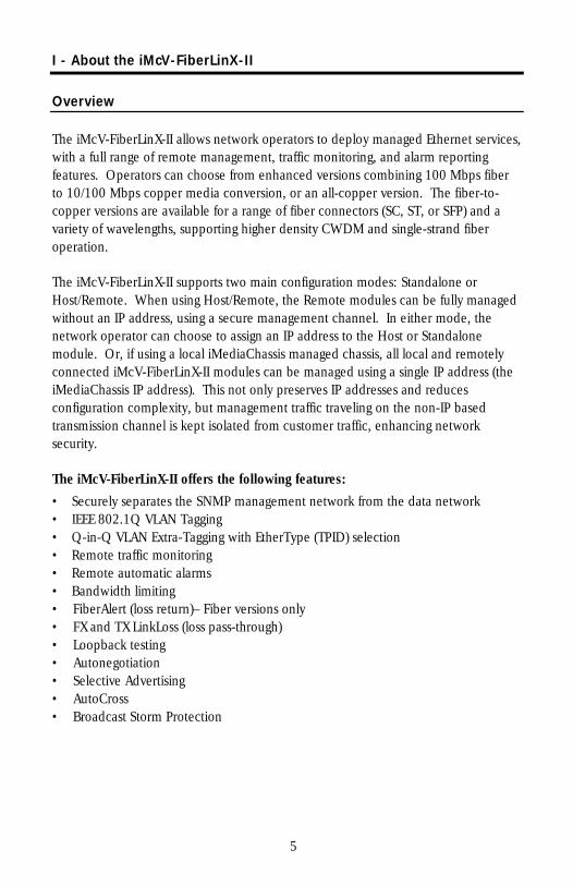
The iMcV-FiberLinX-II module is a single-slot chassis-mounted module.
Compatible chassis include the following:
• iMediaChassis series
• MediaChassis series
• IE-MediaChassis series
Port Interfaces
Every iMcV-FiberLinX-II includes the following ports:
• One 10/100 twisted pair (RJ-45) data port
• One additional 10/100 twisted pair port (EXT MGMT) for management (can also function as a serial port)
And one of the following uplink ports:
• One 100 Mbps Fiber
• One additional 10/100 twisted pair (RJ-45)
• One SFP port (requires one SFP/155-ED Module)
You can easily configure the iMcV-FiberLinX-II by using either the serial craft port connection, through SNMP management application such as iView² or a Telnet session.
Craft Serial Port Connection
The iMcV-FiberLinX-II includes a serial port on the unused pins of the EXT MGMT Ethernet port. Connect a local management PC using the included RJ-45 to DB-9 adapter. This RS-232 serial connection provides access to the iMcV-FiberLinX-II module configuration screens. These configuration screens are also accessible from a Telnet connection.
6
iView2 Management Software
iView² is the IMC Networks management software designed specifically for the IMC Networks “iMcV” family of modules. It features a graphical user interface (GUI) and gives network managers the ability to monitor and control the manageable IMC Networks products.
iView2 is available in several versions and can also function as a snap-in module for HP OpenViewTM Network Node Manager. For assistance in selecting the right version of iView² for your operating system, please visit: http://www.imcnetworks.com/products/iview2.cfm
iView2 supports the following platforms:
Windows™ 98 • Windows NT • Windows 2000 • Windows XP • Windows Vista
In addition, there are Java versions of iView² for other Java capable operating systems such as Linux.
iConfig Utility
iConfig is a configuration utility in iView² that lets you quickly and easily complete the initial SNMP configuration for IMC Networks’ SNMP-manageable devices. With iConfig you can set the IP address, set the Subnet Mask and Default Gateway, define the Community Strings, and define SNMP Traps. iConfig can also be used to upload new versions of unit software.
iConfig offers an authorized IP address system and access restriction to MIB groups supported by the IMC Networks manageable devices. These extra layers of security are purely optional and do not effect SNMP compatibility in any way.
Default Username/Password
The default user ID and password for both iConfig and Telnet are the following:
User: admin / Password: admin
For information on how to set/change passwords, see page 19.
NOTE
It is the responsibility of the network administrator to store and maintain the password lists.
7

About Dynamic Host Control Protocol (DHCP)
The iMcV-FiberLinX-II module includes a Dynamic Host Control Protocol (DHCP) client. By default, the DHCP client is disabled. When a DHCP server is enabled on the network, the DHCP client will initiate a dialogue with the server during the boot up sequence. The server will then issue an IP address, Default Gateway address and Subnet mask to the module. After the new IP address is received, the iMcV-FiberLinX-II will reboot with the new IP address. When a DHCP server is not on the network, ensure that DHCP is disabled and use iConfig or serial configuration to manually set the IP addresses (refer to the Serial Configuration/Telnet Session section for DHCP Enable/Disable information).
If an IP address is already assigned to the device, and DHCP is then enabled, that original IP address is saved. When DHCP is disabled, the saved IP address will be reinstated and the device will reboot.
8
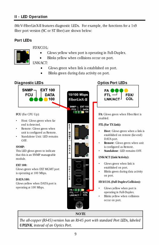
II - LED Operation
iMcV-FiberLinX-II features diagnostic LEDs. For example, the functions for a 1x9 fiber port version (SC or ST fiber) are shown below:
Port LEDs
FDX/COL: • Glows yellow when port is operating in Full-Duplex. • Blinks yellow when collisions occur on port.
LNK/ACT: • Glows green when link is established on port. • Blinks green during data activity on port.
Diagnostic LEDs Optics Port LEDs
FCU (Far CPU Up):
• Host: Glows green when far end is detected.
• Remote: Glows green when unit is configured as Remote.
• Standalone Unit: LED remains OFF.
SNMP: This LED glows green to indicate that this is an SNMP manageable module.
EXT 100: Glows green when EXT MGMT port is operating at 100 Mbps.
DATA 100: Glows yellow when DATA port is operating at 100 Mbps.
FA: Glows green when FiberAlert is enabled.
FTL (Far TX Link):
• Host: Glows green when a link is established on remote (far-end) DATA port.
• Remote: Glows green when unit is configured as Remote.
• Standalone: LED remains OFF.
LNK/ACT (Link/Activity):
• Glows green when link is established on port.
• Blinks green during data activity on port.
FDX/COL (Full Duplex/Collision):
• Glows yellow when port is operating in Full-Duplex.
• Blinks yellow when collisions occur on port.
NOTE
The all-copper (RJ-45) version has an RJ-45 port with standard Port LEDs, labeled UPLINK, instead of an Optics Port.
9
III - Hardware Configuration
Before installing the module in a chassis, there are two features that must be selected using DIP switches. These selections include the following:
• Enable/Disable management on each port (DIP switches 1, 2, and 3).
• Configure the module to be either a standalone, a host, or a remote (DIP switches 7 and 8).
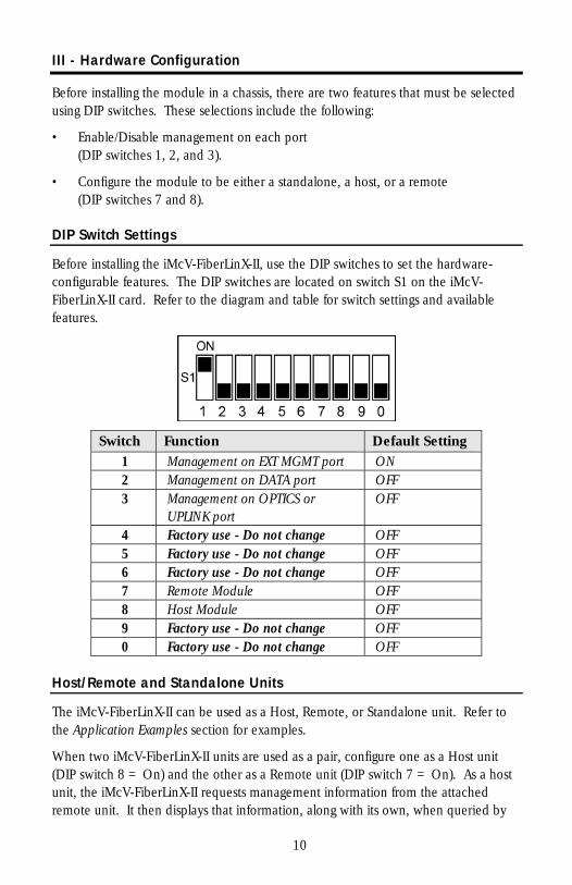
DIP Switch Settings
Before installing the iMcV-FiberLinX-II, use the DIP switches to set the hardware-configurable features. The DIP switches are located on switch S1 on the iMcV-FiberLinX-II card. Refer to the diagram and table for switch settings and available features.
Switch Function Default Setting 1 Management on EXT MGMT port ON 2 Management on DATA port OFF 3 Management on OPTICS or
UPLINK port OFF
4 Factory use - Do not change OFF 5 Factory use - Do not change OFF 6 Factory use - Do not change OFF 7 Remote Module OFF 8 Host Module OFF 9 Factory use - Do not change OFF 0 Factory use - Do not change OFF
Host/Remote and Standalone Units
The iMcV-FiberLinX-II can be used as a Host, Remote, or Standalone unit. Refer to the Application Examples section for examples.
When two iMcV-FiberLinX-II units are used as a pair, configure one as a Host unit (DIP switch 8 = On) and the other as a Remote unit (DIP switch 7 = On). As a host unit, the iMcV-FiberLinX-II requests management information from the attached remote unit. It then displays that information, along with its own, when queried by
10
SNMP. As a Remote unit, the iMcV-FiberLinX-II will respond to requests for management information from an attached Host unit.
The iMcV-FiberLinX-II default configuration is as a Standalone unit (DIP switches 7 and 8 = Off).
Management
Although the iMcV-FiberLinX-II provides a twisted pair port solely for management (EXT MGMT), you can configure iMcV-FiberLinX-II to accept IP-based management traffic from any of its three ports. You can enable management on more than one port, or you can disable management on all of the ports, if desired. These switches limit only IP-based management. Host-to- Remote management is IP-less and is never blocked from the fiber port. Serial port management of the unit is always available on the EXT MGMT port regardless of the DIP switch settings.
In addition to defining which ports are used to manage the iMcV-FiberLinX-II units, the management DIP switch settings also define what ports the flow of the Network Provider’s Management Domain traffic can take through the unit. See Application Examples for information regarding the Management Domain.
DIP switch 1 = On for management on the EXT MGMT port. DIP switch 2 = On for management on the DATA port. DIP switch 3 = On for management on the OPTICS or UPLINK port.
11
IV - Installation Instructions
Each iMcV-FiberLinX-II module requires one slot in an iMediaChassis or MediaChassis. To install the module in a chassis, remove the blank faceplates covering the slots where you want to install the module. Then slide the module into the chassis card guides until the module is seated securely in the connector. Secure the module to the chassis by tightening the captive screw.
The iMcV-FiberLinx-II module includes on-board SNMP logic. A chassis other than an iMediaChassis series cannot manage an iMcV-FiberLinX-II, so the iMcV-FiberLinX-II must be managed independently.
When installed in an iMediaChassis, you can manage the iMcV-FiberLinX-II module from the chassis by using the Unified Management Agent (UMA). Refer to http://www.imcnetworks.com/Products/Unified_Management_Agent.cfm for more information on using UMA with iConfig, iMediaChassis and iMcV-FiberLinX-II. iMcV-FiberLinX-II modules not managed by UMA must have an IP address assigned to them after installation before they can be managed. Refer to (I) - Assigning IP Information for more information.
Small Form-Factor Pluggable Ports (SFP)
iMcV-FiberLinX-II modules are available with an optional SFP port. Since the SFP port speed is fixed at 100Mbps, you must use a 100 Mbps speed SFP. In addition, many SFPs, including those from IMC Networks, feature enhanced diagnostics capabilities with a Digital Diagnostics Monitoring Interface (DDMI). DDMI statistics provide real-time access to transceiver operating parameters such as voltage, temperature, laser bias current, and both transmitted and received optical power. DDMI information can be accessed in iView2 by clicking Tables > SFP Info.
NOTE
iMcV-FiberLinX-II has been tested with the IMC Networks SFP modules. You can install any MSA-compliant SFP module. However, IMC Networks does not guarantee the functionality of non-IMC Networks SFP modules due to possible non-conformity with MSA design standards.
AutoCross Feature for Twisted Pair Connection
All twisted pair ports on the iMcV-FiberLinX-II include AutoCross, a feature that automatically selects between a crossover workstation and a straight-through connection depending on the connected device.
V - Software Configuration
The following sections describe the features you can configure. Refer to the iView² online help for iMcV-FiberLinX-II module configuration information.
12
Assigning IP Information
When the iMcV-FiberLinX-II is installed in an iMediaChassis, you can use UMA to manage your iMcV-FiberLinX-II without an IP address (refer to the iView² online help for more information on UMA). When the iMcV-FiberLinX-II is not installed in an iMediaChassis, SNMP-management is not accessible until the iMcV-FiberLinX-II IP information (e.g., IP address, subnet mask, etc.) is configured (using iConfig, a serial port craft connection, or DHCP). After assigning iMcV-FiberLinX-II an IP address, you can use iView² or another SNMP-compatible Network Management System (NMS) to remotely configure, monitor and manage the iMcV-FiberLinX-II.
Autonegotiation, Duplex Mode, and Speed
The DATA and EXT MGMT ports on the iMcV-FiberLinX-II module autonegotiate for speed and duplex mode. This module also provides the option of selectively advertising or forcing the speed and duplex mode.
Autonegotiation
The iMcV-FiberLinX-II ships from the factory with autonegotiation enabled on the twisted-pair ports. In this mode, the ports negotiate for speed and duplex.
Forcing the Speed and Duplex Mode
You can manually set the twisted-pair ports on the iMcV-FiberLinX-II for 10 Mbps or 100 Mbps operation at Half- or Full-Duplex (i.e., 10 Mbps Full-Duplex, 10 Mbps Half-Duplex, 100 Mbps Full-Duplex, etc.). The Optics Port operates at 100Mbps Full-Duplex.
Selective Advertising
Selective Advertising, when used in combination with Autonegotiation, advertises only the configured speed and duplex mode for the twisted pair port. If a specific speed and/or duplex mode are desired, IMC Networks recommends using Selective Advertising, rather than Force Mode, when connecting to devices that only use autonegotiation.
Bandwidth Control
The iMcV-FiberLinX-II includes bi-directional bandwidth control in 32 Kbps increments (configurable via iView2). This allows you to independently set the bandwidth limit from the DATA Port to the OPTICS (or UPLINK) Port and vice versa in a single iMcV-FiberLinX-II application. In a dual iMcV-FiberLinX-II application you can set it from the Host unit to the Remote unit and vice versa (i.e., the bandwidth
13
on the DATA ports on both the Host and Remote modules can be limited independently).
NOTE
Management packets do not have priority over data packets.
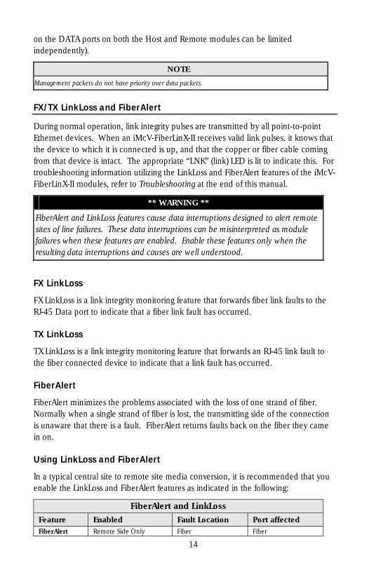
FX/TX LinkLoss and FiberAlert
During normal operation, link integrity pulses are transmitted by all point-to-point Ethernet devices. When an iMcV-FiberLinX-II receives valid link pulses, it knows that the device to which it is connected is up, and that the copper or fiber cable coming from that device is intact. The appropriate “LNK” (link) LED is lit to indicate this. For troubleshooting information utilizing the LinkLoss and FiberAlert features of the iMcV-FiberLinX-II modules, refer to Troubleshooting at the end of this manual.
** WARNING **
FiberAlert and LinkLoss features cause data interruptions designed to alert remote sites of line failures. These data interruptions can be misinterpreted as module failures when these features are enabled. Enable these features only when the resulting data interruptions and causes are well understood.
FX LinkLoss
FX LinkLoss is a link integrity monitoring feature that forwards fiber link faults to the RJ-45 Data port to indicate that a fiber link fault has occurred.
TX LinkLoss
TX LinkLoss is a link integrity monitoring feature that forwards an RJ-45 link fault to the fiber connected device to indicate that a link fault has occurred.
FiberAlert
FiberAlert minimizes the problems associated with the loss of one strand of fiber. Normally when a single strand of fiber is lost, the transmitting side of the connection is unaware that there is a fault. FiberAlert returns faults back on the fiber they came in on.
Using LinkLoss and FiberAlert
In a typical central site to remote site media conversion, it is recommended that you enable the LinkLoss and FiberAlert features as indicated in the following:
FiberAlert and LinkLoss Feature Enabled Fault Location Port affected FiberAlert Remote Side Only Fiber Fiber
14
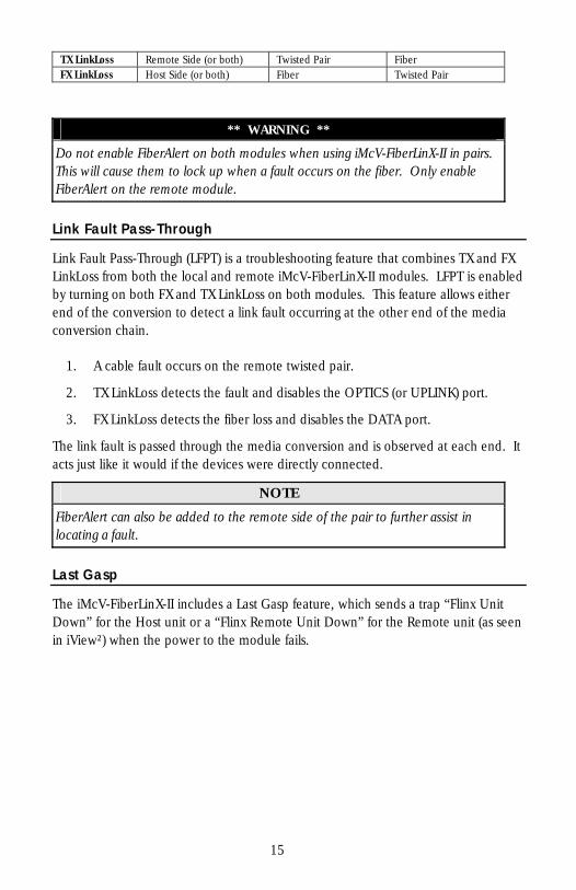
TX LinkLoss Remote Side (or both) Twisted Pair Fiber FX LinkLoss Host Side (or both) Fiber Twisted Pair
** WARNING **
Do not enable FiberAlert on both modules when using iMcV-FiberLinX-II in pairs. This will cause them to lock up when a fault occurs on the fiber. Only enable FiberAlert on the remote module.
Link Fault Pass-Through
Link Fault Pass-Through (LFPT) is a troubleshooting feature that combines TX and FX LinkLoss from both the local and remote iMcV-FiberLinX-II modules. LFPT is enabled by turning on both FX and TX LinkLoss on both modules. This feature allows either end of the conversion to detect a link fault occurring at the other end of the media conversion chain.
1. A cable fault occurs on the remote twisted pair.
2. TX LinkLoss detects the fault and disables the OPTICS (or UPLINK) port.
3. FX LinkLoss detects the fiber loss and disables the DATA port.
The link fault is passed through the media conversion and is observed at each end. It acts just like it would if the devices were directly connected.
NOTE
FiberAlert can also be added to the remote side of the pair to further assist in locating a fault.
Last Gasp
The iMcV-FiberLinX-II includes a Last Gasp feature, which sends a trap “Flinx Unit Down” for the Host unit or a “Flinx Remote Unit Down” for the Remote unit (as seen in iView²) when the power to the module fails.
15
Loopback Testing on Remote or Standalone
The following functions are available during loopback testing. During loopback testing, management traffic entering the uplink port is still capable of managing the device.
Address Swap
A Layer 2 Ethernet switch will discard all received packets with the same MAC address as sent packets. To avoid this issue the Loopback feature can swap the source and destination MAC addresses on the looped data.
Address Swap and Clear Multicast Bit
In addition to swapping the source and destination MAC addresses on the looped data, the Loopback feature can also be set to clear the multicast bit. This allows the looped data to avoid being blocked by any multicast settings.
No Learning on OPTICS and DATA Ports
The Loopback feature can be set to disable address learning on the OPTICS (or UPLINK) and DATA ports, allowing the loopback to be performed without interference from MAC address filtering functions. This is a function on the HOST unit. Set the REMOTE unit for Loopback then set the HOST to disable learning so Loopback frames pass from the Optics port to the Data port.
Broadcast Storm Protection
Broadcast Storm Protection allows you to set the maximum broadcast packet rate allowed as a percentage of line speed (from 0% - 20%). The suggested value is 1%.
16
VI - Using Telnet
You must assign the iMcV-FiberLinX-II an IP address before using a Telnet session (this is not necessary when you are using UMA). Refer to the Assigning IP Information section for more information. All of the configurations that you can perform from the serial port can also be performed using a Telnet session. You can only use one Telnet session at a time.
The following are the three levels for Telnet account access:
User: View status, change own password, and reboot. Operator: All User privileges mentioned above, plus ability to change settings. Administrator: Operator privileges mentioned above, plus ability to add/delete accounts and reinitialize the unit to default settings (cleandb).
Serial Configuration/Telnet Session
The following sections describe serial configuration (including VLAN configuration), Telnet session configuration, and DHCP configuration.
NOTE
Some screens may show TX and FX for the port titles where TX = DATA port and FX = OPTICS (or UPLINK) port. The examples are from firmware version 512-00A2.
Serial Port (EXT MGMT)
NOTE
The serial port (EXT MGMT) is always set to Administrator level. Your password for Telnet sessions is the password that you set and use in iConfig (refer to the iConfig section for more information).
17
Basic Device Configuration
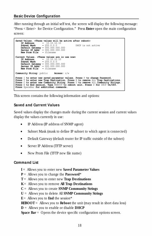
After running through an initial self test, the screen will display the following message: “Press <Enter> for Device Configuration.” Press Enter open the main configuration screen:
Saved Values. <These values will be active after reboot> IP Address - 10.10.10.10
DHCP is not active Subnet Mask - 255.0.0.0 Default Gateway - 000.000.000.000
000.000.000.000 Server IP Addr - New Prom File - filename
n use now> Current Values. <These values are i
10 IP Address - 10.10.10. Subnet Mask - 255.0.0.0 Default Gateway - 000.000.000.000
000.000.000.000 Server IP Addr - New Prom File - filename
mmunity String: public Access: r/w Co
Press I to enter new saved parameter values. Press P to change Password. Press T to enter new Trap Destination. Press K to remove ALL Trap Destinations.
s. Press C to enter new Community String. Press U to remove ALL Community Stringboot unit. Press D for DHCP On/Off. Press E to End session. Type REBOOT to re
Press SpaceBar for additional commands.
This screen contains the following information and options:
Saved and Current Values
Saved values display the changes made during the current session and current values display the values currently in use:
• IP Address (IP address of SNMP agent)
• Subnet Mask (mask to define IP subnet to which agent is connected)
• Default Gateway (default router for IP traffic outside of the subnet)
• Server IP Address (TFTP server)
• New Prom File (TFTP new file name)
Command List
I = Allows you to enter new Saved Parameter Values P = Allows you to change the Password* T = Allows you to enter new Trap Destinations K = Allows you to remove All Trap Destinations C = Allows you to create SNMP Community Strings U = Allows you to delete All SNMP Community Strings E = Allows you to End the session* REBOOT = Allows you to Reboot the unit (may result in short data loss) D = Allows you to enable or disable DHCP Space Bar = Opens the device specific configuration options screen.
18
* Individuals with User-level rights can only view port status and port settings, change their password, end a session, and reboot the unit.
NOTE
You must reboot the iMcV-FiberLinX-II after making any modifications to the Saved Values for your changes to take effect. To reboot, type the word reboot at the prompt on the Main Configuration screen.
(I) - Assigning IP Information
To modify the Saved Parameter Values (i.e., assign the IP address and subnet mask), press I. You will be prompted to enter the IP address and subnet mask for the connected device. Press Enter after each entry. You can also assign a default gateway to allow the unit to be visible beyond the local network (press Enter to skip). When finished, press Enter, then type reboot for the changes to take effect. The Current Values on the Main Configuration screen are updated to match the Saved Values.
(P) - Password Protection/Changing Password
Passwords have the following requirements:
• The password must be between 1 and 8 characters long • The password consists of a combination of any ASCII characters except spaces • Passwords are case sensitive
You can password protect the serial port by pressing P in the Main Configuration screen. You will be prompted to enter a password. Enter your password (do not use spaces) and press Enter. You will then be asked for your password whenever you log on. To remove password protection, select P and instead of entering a password, press Enter.
Passwords are a way to make the management of the IMC Networks devices secure. It is your responsibility to store and maintain the password lists. If the passwords are lost, neither you nor IMC Networks has a way to "decode" it. Refer to the iView² iConfig online help for more password information.
If the serial password is forgotten, you must contact tech support for assistance in resetting the password. If the iConfig username and password are forgotten, you can launch a console session through the serial port, and type in the command cleandb. If both the serial and the iConfig passwords are forgotten, you must contact technical support.
19
(T) - Assigning SNMP Trap Destinations
Traps are sent by the manageable device to a management PC when a certain event takes place. To enter a trap destination, press T. You will then be asked to “Enter a New IP Address.” Type the IP address of the destination device and press Enter. Next, type the name of the community string (that the destination device has been configured to accept) and press Enter. Select whether the trap is for SNMP version 1 or 2c and press Enter. This function enables all of the device traps. When you want to selectively activate and de-activate traps, use iConfig to configure your device.
Supported traps include: Link Down, Link Up, Cold Start, Warm Start, Last Gasp, and Authentication Failure.
When deployed in pairs, iMcV-FiberLinX-II also supports the following traps:
• Remote Unit Lost • Remote Unit Found • Far End TX Link Up • Far End TX Link Down • Remote Unit Cold Start • Remote Unit Warm Start
(K) - Removing All SNMP Trap Destinations
To remove all trap destinations, press K. You will then be prompted, “Are you sure you want to delete all trap destinations?” Press Y to continue, press N to abort. Press Enter to finish.
This function will delete all trap destinations. If you want to be able to selectively delete trap destinations or select the type of trap reported or not reported, use iConfig to configure your device.
(C) - Creating SNMP Community Strings
The default community string is named “public” and has read/write access. It is recommended that you create custom community strings (with read-only access for general use and another with read/write access for the administrator) and test them before deleting “Public”. To create a new community string, go to the main configuration screen and press C. Enter the name of the new community (up to 16 characters, no spaces) and press Enter. Then type one of the following to assign the community string’s access rights:
• R = read-only access • W = read/write access • Enter = abort
20
(U) - Deleting All SNMP Community Strings
To delete all community strings and start over, press U. You will then be prompted, “Are you sure you want to delete all community strings?” Press Y to proceed, N to abort. Press Enter to finish.
This function will delete all community strings. If you want to be able to selectively delete community strings, use iConfig to configure your device.
(E) - Ending Your Session
Ensure you press E to end the session before disconnecting the serial cable. This will stop the continuous stream of data that is sent to the serial port.
(REBOOT) – Reboot Device
By typing REBOOT, the device will restart, which will result in a temporary loss of operation of the unit while it re-initializes.
(D) – Enabling DHCP
By pressing D, a screen will appear which will allow you to enable or disable DHCP for the device. By default, the DHCP client is disabled.
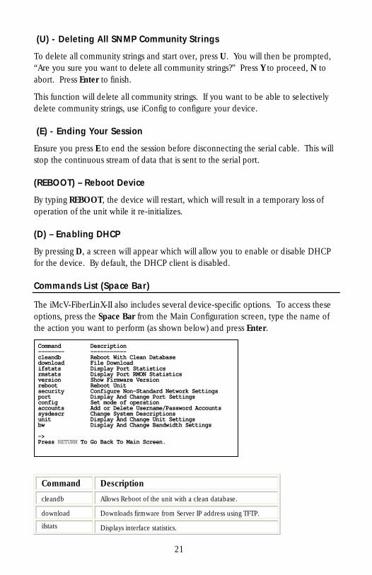
Commands List (Space Bar)
The iMcV-FiberLinX-II also includes several device-specific options. To access these options, press the Space Bar from the Main Configuration screen, type the name of the action you want to perform (as shown below) and press Enter.
Command Description
cleandb Allows Reboot of the unit with a clean database.
download Downloads firmware from Server IP address using TFTP.
ifstats Displays interface statistics.
Command Description-------- -----------
ean Database cleandb Reboot With Cldownload File Download ifstats Display Port Statistics
istics rmstats Display Port RMON State Version version Show Firmwar
reboot Reboot Unit ttings security Configure Non-Standard Network Se
t Settings port Display And Change Porconfig Set mode of operation
word Accounts accounts Add or Delete Username/Passsysdescr Change System Descriptions unit Display And Change Unit Settings Display And Change Bandwidth Settings bw
-> Press RETURN To Go Back To Main Screen.
21
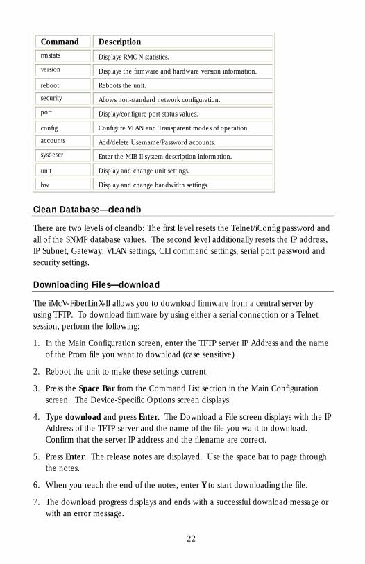
Command Description rmstats Displays RMON statistics.
version Displays the firmware and hardware version information.
reboot Reboots the unit.
security Allows non-standard network configuration.
port Display/configure port status values.
config Configure VLAN and Transparent modes of operation.
accounts Add/delete Username/Password accounts.
sysdescr Enter the MIB-II system description information.
unit Display and change unit settings.
bw Display and change bandwidth settings.
Clean Database—cleandb
There are two levels of cleandb: The first level resets the Telnet/iConfig password and all of the SNMP database values. The second level additionally resets the IP address, IP Subnet, Gateway, VLAN settings, CLI command settings, serial port password and security settings.
Downloading Files—download
The iMcV-FiberLinX-II allows you to download firmware from a central server by using TFTP. To download firmware by using either a serial connection or a Telnet session, perform the following:
1. In the Main Configuration screen, enter the TFTP server IP Address and the name of the Prom file you want to download (case sensitive).
2. Reboot the unit to make these settings current.
3. Press the Space Bar from the Command List section in the Main Configuration screen. The Device-Specific Options screen displays.
4. Type download and press Enter. The Download a File screen displays with the IP Address of the TFTP server and the name of the file you want to download. Confirm that the server IP address and the filename are correct.
5. Press Enter. The release notes are displayed. Use the space bar to page through the notes.
6. When you reach the end of the notes, enter Y to start downloading the file.
7. The download progress displays and ends with a successful download message or with an error message.
22
8. Press Q or F4 to return to the Device-Specific Options screen.
When the iMcV-FiberLinX-II is installed in a managed chassis, you have option of using UMA to update the firmware (refer to the iView2 online help for more information on using UMA with iConfig, iMediaChassis and iMcV-FiberLinX-II).
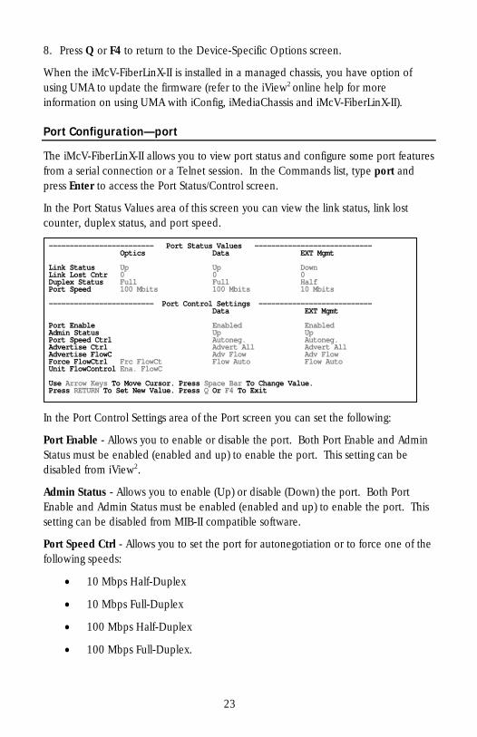
Port Configuration—port
The iMcV-FiberLinX-II allows you to view port status and configure some port features from a serial connection or a Telnet session. In the Commands list, type port and press Enter to access the Port Status/Control screen.
In the Port Status Values area of this screen you can view the link status, link lost counter, duplex status, and port speed.
------------------------- Port Status Values -------------------- Optics Data EXT Mgmt
--------
wn Link Status Up Up DoLink Lost Cntr 0 0 0 Duplex Status Full Full Half rt Speed 100 Mbits 100 Mbits 10 Mbits Po
------- ------------------------- Port Control Settings --------------------
Data EXT Mgmt
bled Port Enable Enabled EnaAdmin Status Up Up Port Speed Ctrl Autoneg. Autoneg.
l Advertise Ctrl Advert All Advert AlAdvertise FlowC Adv Flow Adv Flow
Flow Auto Flow Auto Force FlowCtrl Frc FlowCt it FlowControl Ena. FlowC Un
ge Value. Use Arrow Keys To Move Cursor. Press Space Bar To Chan
Press RETURN To Set New Value. Press Q Or F4 To Exit
In the Port Control Settings area of the Port screen you can set the following:
Port Enable - Allows you to enable or disable the port. Both Port Enable and Admin Status must be enabled (enabled and up) to enable the port. This setting can be disabled from iView2.
Admin Status - Allows you to enable (Up) or disable (Down) the port. Both Port Enable and Admin Status must be enabled (enabled and up) to enable the port. This setting can be disabled from MIB-II compatible software.
Port Speed Ctrl - Allows you to set the port for autonegotiation or to force one of the following speeds:
• 10 Mbps Half-Duplex
• 10 Mbps Full-Duplex
• 100 Mbps Half-Duplex
• 100 Mbps Full-Duplex.
23
Advertise Ctrl - This is the Selective Advertising feature. Selective Advertising is used in combination with autonegotiation to advertise your selected speed and duplex mode for the DATA and EXT MGMT ports. This allows you to advertise: all speeds and duplex modes; 10 Mbps Half-Duplex; 10 Mbps Full-Duplex; 100 Mbps Half-Duplex; 100 Mbps Full-Duplex; 10 Mbps Half and Full-Duplex; etc. You must enable Autonegotiation for Selective Advertising to work.
NOTE
If a specific speed and/or duplex mode are desired, IMC Networks recommends using Selective Advertising, instead of Force Mode, when connecting to devices that can only autonegotiate. For the FO uplink versions, the port is always force flow control 100 FDX and cannot be changed.
Advertise FlowC and Force FlowCtrl—the following are Advertise Control features.
When using Flow Control functionality on any port, you must enable Flow Control (refer to Unit Flow Control for more information). Next, configure each port individually:
• To use Autonegotiation and Flow Control: Advertise FlowC = Advertise Flow, Force FlowCtrl = Flow Auto
• To use Autonegotiation but not Flow Control Advertise FlowC = No Flow
• To use Flow Control and force the port speed (Port Speed Ctrl) Advertise FlowC = Advertise Flow, Force FlowCtrl = Frc FlowCt
All RJ-45 ports feature Flow Control in Full-Duplex and Back Pressure Flow control in Half-Duplex. Back Pressure Flow Control is a hardware based flow control that forces collisions on the line to limit bandwidth.
Unit FlowControl—allows you to enable or disable Flow Control functionality on the unit. You must enable this to use Flow Control on any port.
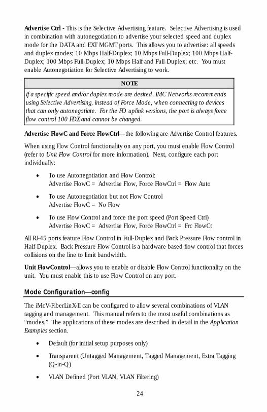
Mode Configuration—config
The iMcV-FiberLinX-II can be configured to allow several combinations of VLAN tagging and management. This manual refers to the most useful combinations as “modes.” The applications of these modes are described in detail in the Application Examples section.
• Default (for initial setup purposes only)
• Transparent (Untagged Management, Tagged Management, Extra Tagging (Q-in-Q)
• VLAN Defined (Port VLAN, VLAN Filtering)
24
NOTE
Default mode is the factory default and is provided as a starting point from which to configure the iMcV-FiberLinX-II modules. This mode does not provide adequate management isolation and is not recommended for normal use.
This section describes the Telnet/serial port screens and fields available for configuring the iMcV-FiberLinX-II modes.
The iMcV-FiberLinX-II modes are configured using the config command from the Device-Specific Options screen. This opens the Transparent Mode screen or the VLAN Mode screen depending on the current configuration.
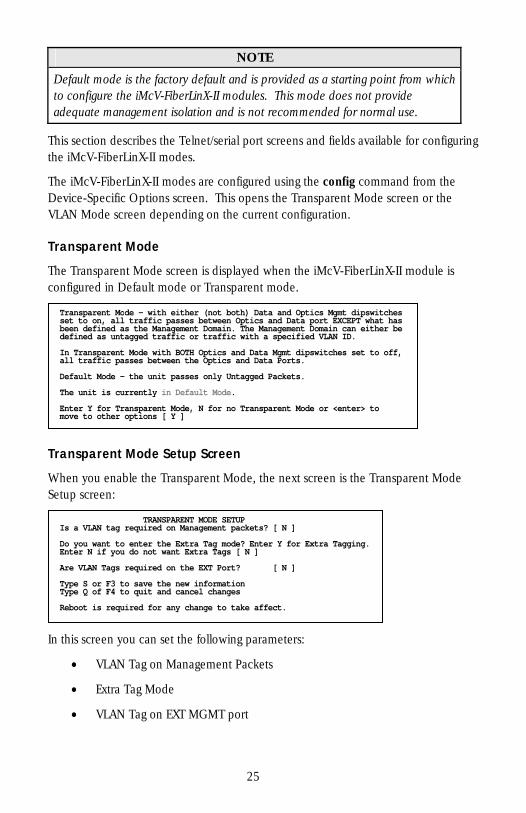
Transparent Mode
The Transparent Mode screen is displayed when the iMcV-FiberLinX-II module is configured in Default mode or Transparent mode.
Transparent Mode – with either (not both) Data and Optics Mgmt dipswitchesset to on, all traffic passes between Optics and Data port EXCEPT what has been defined as the Management Domain. The Management Domain can either be efined as untagged traffic or traffic with a specified VLAN ID. d In Transparent Mode with BOTH Optics and Data Mgmt dipswitches set to off, ll traffic passes between the Optics and Data Ports. a efault Mode – the unit passes only Untagged Packets. D he unit is currently in Default Mode. T Enter Y for Transparent Mode, N for no Transparent Mode or <enter> to move to other options [ Y ]
Transparent Mode Setup Screen
When you enable the Transparent Mode, the next screen is the Transparent Mode Setup screen:
TRANSPARENT MODE SETUPIs a VLAN tag required on Management packets? [ N ]
er Y for Extra Tagging. Do you want to enter the Extra Tag mode? Entnter N if you do not want Extra Tags [ N ] E re VLAN Tags required on the EXT Port? [ N ] A
Type S or F3 to save the new informationype Q of F4 to quit and cancel changes T Reboot is required for any change to take affect.
In this screen you can set the following parameters:
• VLAN Tag on Management Packets
• Extra Tag Mode
• VLAN Tag on EXT MGMT port
25
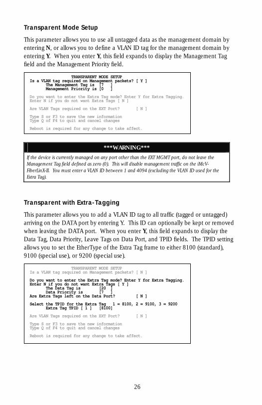
Transparent Mode Setup
This parameter allows you to use all untagged data as the management domain by entering N, or allows you to define a VLAN ID tag for the management domain by entering Y. When you enter Y, this field expands to display the Management Tag field and the Management Priority field.
TRANSPARENT MODE SETUPIs a VLAN tag required on Management packets? [ Y ] The Management Tag is [7 ] Management Priority is [0 ]
er Y for Extra Tagging. Do you want to enter the Extra Tag mode? Entnter N if you do not want Extra Tags [ N ] E re VLAN Tags required on the EXT Port? [ N ] A
Type S or F3 to save the new informationype Q of F4 to quit and cancel changes T Reboot is required for any change to take affect.
***WARNING***
If the device is currently managed on any port other than the EXT MGMT port, do not leave the Management Tag field defined as zero (0). This will disable management traffic on the iMcV-FiberLinX-II. You must enter a VLAN ID between 1 and 4094 (excluding the VLAN ID used for the Extra Tag).
Transparent with Extra-Tagging
This parameter allows you to add a VLAN ID tag to all traffic (tagged or untagged) arriving on the DATA port by entering Y. This ID can optionally be kept or removed when leaving the DATA port. When you enter Y, this field expands to display the Data Tag, Data Priority, Leave Tags on Data Port, and TPID fields. The TPID setting allows you to set the EtherType of the Extra Tag frame to either 8100 (standard), 9100 (special use), or 9200 (special use).
TRANSPARENT MODE SETUPIs a VLAN tag required on Management packets? [ N ]
er Y for Extra Tagging. Do you want to enter the Extra Tag mode? Ent [ Y ] Enter N if you do not want Extra Tags
The Data Tag is [20 ] Data Priority is [7 ] re Extra Tags left on the Data Port? [ N ] A
= 8100, 2 = 9100, 3 = 9200 Select the TPID for the Extra Tag 1 Extra Tag TPID [ 1 ] [8100] re VLAN Tags required on the EXT Port? [ N ] A
Type S or F3 to save the new informationype Q of F4 to quit and cancel changes T Reboot is required for any change to take affect.
26
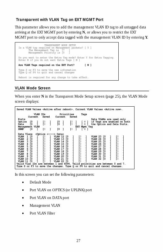
Transparent with VLAN Tag on EXT MGMT Port
This parameter allows you to add the management VLAN ID tag to all untagged data arriving at the EXT MGMT port by entering N, or allows you to restrict the EXT MGMT port to only accept data tagged with the management VLAN ID by entering Y.
TRANSPARENT MODE SETUPIs a VLAN tag required on Management packets? [ Y ] The Management Tag is [7 ] Management Priority is [0 ]
er Y for Extra Tagging. Do you want to enter the Extra Tag mode? Entnter N if you do not want Extra Tags [ N ] E re VLAN Tags required on the EXT Port? [ N ] A
Type S or F3 to save the new informationype Q of F4 to quit and cancel changes T Reboot is required for any change to take affect.
VLAN Mode Screen
When you enter N in the Transparent Mode Setup screen (page 25), the VLAN Mode screen displays:
Saved VLAN Values <Active after reboot>. Current VLAN Values <Active now>.
Tags VLAN IDs Priorities Current Saved Current Saved Ports Data VLANs are used only
Optics [0 ] [0 ] [0 ] [0 ] [ N ] if Tags are enabled on bothe Optics and Data Ports. Data [0 ] [0 ] [0 ] [0 ] [ N ] th
Management VLAN EXT Mgmt Tag NMP [0 ] [0 ] [0 ] [0 ] [ N ] S
Data Vlans <Optics <----> Data> VLAN 1 [0 ] [0 ] VLAN 12 [0 ] [0 ] VLAN 23 [0 ] [0 ] VLAN 2 [0 ] [0 ] VLAN 13 [0 ] [0 ] VLAN 24 [0 ] [0 ] VLAN 3 [0 ] [0 ] VLAN 14 [0 ] [0 ] VLAN 25 [0 ] [0 ] VLAN 4 [0 ] [0 ] VLAN 15 [0 ] [0 ] VLAN 26 [0 ] [0 ] VLAN 5 [0 ] [0 ] VLAN 16 [0 ] [0 ] VLAN 27 [0 ] [0 ] VLAN 6 [0 ] [0 ] VLAN 17 [0 ] [0 ] VLAN 28 [0 ] [0 ] VLAN 7 [0 ] [0 ] VLAN 18 [0 ] [0 ] VLAN 29 [0 ] [0 ] VLAN 8 [0 ] [0 ] VLAN 19 [0 ] [0 ] VLAN 30 [0 ] [0 ] VLAN 9 [0 ] [0 ] VLAN 20 [0 ] [0 ] VLAN 31 [0 ] [0 ]
VLAN 32 [0 ] [0 ] VLAN 10 [0 ] [0 ] VLAN 21 [0 ] [0 ] VLAN 11 [0 ] [0 ] VLAN 22 [0 ] [0 ]
7. Valid Vlan IDs are between 1 and 4094. Valid priorities are between 0 and Type S or F3 to save the changes. Type Q or F4 to quit and cancel changes.
In this screen you can set the following parameters:
• Default Mode
• Port VLAN on OPTICS (or UPLINK) port
• Port VLAN on DATA port
• Management VLAN
• Port VLAN Filter
27
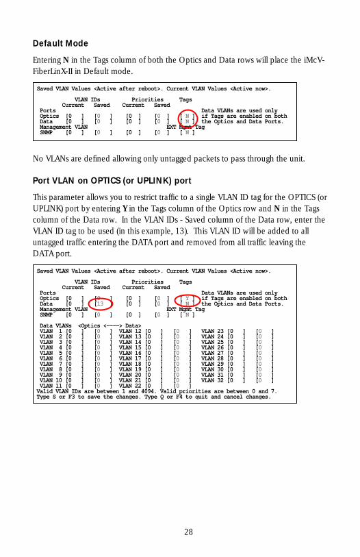
Default Mode
Entering N in the Tags column of both the Optics and Data rows will place the iMcV-FiberLinX-II in Default mode.
No VLANs are defined allowing only untagged packets to pass through the unit.
Port VLAN on OPTICS (or UPLINK) port
This parameter allows you to restrict traffic to a single VLAN ID tag for the OPTICS (or UPLINK) port by entering Y in the Tags column of the Optics row and N in the Tags column of the Data row. In the VLAN IDs - Saved column of the Data row, enter the VLAN ID tag to be used (in this example, 13). This VLAN ID will be added to all untagged traffic entering the DATA port and removed from all traffic leaving the DATA port.
Saved VLAN Values <Active after reboot>. Current VLAN Values <Active now>.
Tags VLAN IDs Priorities Current Saved Current Saved Ports Data VLANs are used only
Optics [0 ] [0 ] [0 ] [0 ] [ N ] if Tags are enabled on bothe Optics and Data Ports. Data [0 ] [0 ] [0 ] [0 ] [ N ] th
Management VLAN EXT Mgmt Tag SNMP [0 ] [0 ] [0 ] [0 ] [ N ]
Saved VLAN Values <Active after reboot>. Current VLAN Values <Active now>.
Tags VLAN IDs Priorities Current Saved Current Saved Ports Data VLANs are used only
Optics [0 ] [0 ] [0 ] [0 ] [ Y ] if Tags are enabled on bothe Optics and Data Ports. Data [0 ] [13 ] [0 ] [0 ] [ N ] th
Management VLAN EXT Mgmt Tag NMP [0 ] [0 ] [0 ] [0 ] [ N ] S
Data VLANs <Optics <----> Data> VLAN 1 [0 ] [0 ] VLAN 12 [0 ] [0 ] VLAN 23 [0 ] [0 ] VLAN 2 [0 ] [0 ] VLAN 13 [0 ] [0 ] VLAN 24 [0 ] [0 ] VLAN 3 [0 ] [0 ] VLAN 14 [0 ] [0 ] VLAN 25 [0 ] [0 ] VLAN 4 [0 ] [0 ] VLAN 15 [0 ] [0 ] VLAN 26 [0 ] [0 ] VLAN 5 [0 ] [0 ] VLAN 16 [0 ] [0 ] VLAN 27 [0 ] [0 ] VLAN 6 [0 ] [0 ] VLAN 17 [0 ] [0 ] VLAN 28 [0 ] [0 ] VLAN 7 [0 ] [0 ] VLAN 18 [0 ] [0 ] VLAN 29 [0 ] [0 ] VLAN 8 [0 ] [0 ] VLAN 19 [0 ] [0 ] VLAN 30 [0 ] [0 ] VLAN 9 [0 ] [0 ] VLAN 20 [0 ] [0 ] VLAN 31 [0 ] [0 ]
VLAN 32 [0 ] [0 ] VLAN 10 [0 ] [0 ] VLAN 21 [0 ] [0 ] VLAN 11 [0 ] [0 ] VLAN 22 [0 ] [0 ]
7. Valid VLAN IDs are between 1 and 4094. Valid priorities are between 0 and Type S or F3 to save the changes. Type Q or F4 to quit and cancel changes.
28
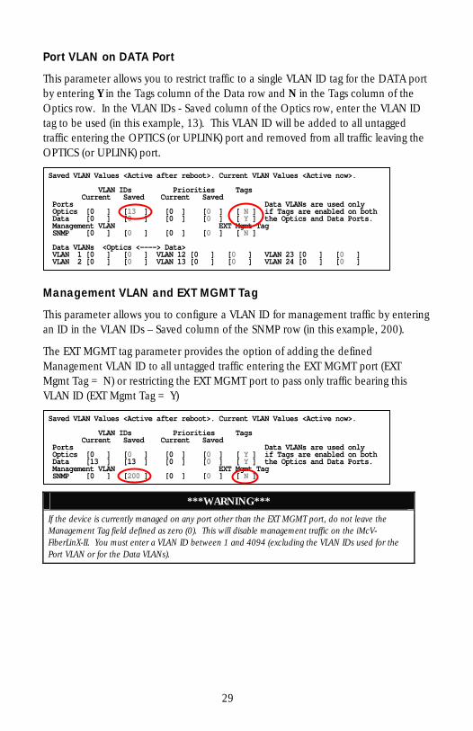
Port VLAN on DATA Port
This parameter allows you to restrict traffic to a single VLAN ID tag for the DATA port by entering Y in the Tags column of the Data row and N in the Tags column of the Optics row. In the VLAN IDs - Saved column of the Optics row, enter the VLAN ID tag to be used (in this example, 13). This VLAN ID will be added to all untagged traffic entering the OPTICS (or UPLINK) port and removed from all traffic leaving the OPTICS (or UPLINK) port.
Management VLAN and EXT MGMT Tag
This parameter allows you to configure a VLAN ID for management traffic by entering an ID in the VLAN IDs – Saved column of the SNMP row (in this example, 200).
The EXT MGMT tag parameter provides the option of adding the defined Management VLAN ID to all untagged traffic entering the EXT MGMT port (EXT Mgmt Tag = N) or restricting the EXT MGMT port to pass only traffic bearing this VLAN ID (EXT Mgmt Tag = Y)
Saved VLAN Values <Active after reboot>. Current VLAN Values <Active now>.
Tags VLAN IDs Priorities Current Saved Current Saved Ports Data VLANs are used only
Optics [0 ] [0 ] [0 ] [0 ] [ Y ] if Tags are enabled on bothe Optics and Data Ports. Data [13 ] [13 ] [0 ] [0 ] [ Y ] th
t Management VLAN EXT Mgm Tag SNMP [0 ] [200 ] [0 ] [0 ] [ N ]
Saved VLAN Values <Active after reboot>. Current VLAN Values <Active now>.
Tags VLAN IDs Priorities Current Saved Current Saved Ports Data VLANs are used only
Optics [0 ] [13 ] [0 ] [0 ] [ N ] if Tags are enabled on bothe Optics and Data Ports. Data [0 ] [0 ] [0 ] [0 ] [ Y ] th
Management VLAN EXT Mgmt Tag NMP [0 ] [0 ] [0 ] [0 ] [ N ] S
Data VLANs <Optics <----> Data>
] VLAN 1 [0 ] [0 ] VLAN 12 [0 ] [0 ] VLAN 23 [0 ] [0 VLAN 2 [0 ] [0 ] VLAN 13 [0 ] [0 ] VLAN 24 [0 ] [0 ]
***WARNING***
If the device is currently managed on any port other than the EXT MGMT port, do not leave the Management Tag field defined as zero (0). This will disable management traffic on the iMcV-FiberLinX-II. You must enter a VLAN ID between 1 and 4094 (excluding the VLAN IDs used for the Port VLAN or for the Data VLANs).
29
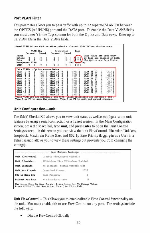
Port VLAN Filter
This parameter allows you to pass traffic with up to 32 separate VLAN IDs between the OPTICS (or UPLINK) port and the DATA port. To enable the Data VLANS fields, you must enter Y in the Tags column for both the Optics and Data rows. Enter up to 32 VLAN IDs in the Data VLANs fields.
Unit Configuration—unit
The iMcV-FiberLinX-II allows you to view unit status as well as configure some unit features by using a serial connection or a Telnet session. In the Main Configuration screen, press the space bar, type unit, and press Enter to open the Unit Control Settings screen. In this screen you can view the unit FlowControl, FiberAlert/LinkLoss, Loopback, Maximum Frame Size, and 802.1p Base Priority (logging-in as a User in a Telnet session allows you to view these settings but prevents you from changing the settings).
Saved VLAN Values <Active after reboot>. Current VLAN Values <Active now>.
Tags VLAN IDs Priorities Current Saved Current Saved Ports Data VLANs are used only
Optics [0 ] [0 ] [0 ] [0 ] [ Y ] if Tags are enabled on bothe Optics and Data Ports. Data [0 ] [0 ] [0 ] [0 ] [ Y ] th
Management VLAN EXT Mgmt Tag NMP [0 ] [0 ] [0 ] [0 ] [ N ] S
Data VLANs <Optics <----> Data> VLAN 1 [0 ] [900 ] VLAN 12 [0 ] [911 ] VLAN 23 [0 ] [922 ] VLAN 2 [0 ] [901 ] VLAN 13 [0 ] [912 ] VLAN 24 [0 ] [923 ] VLAN 3 [0 ] [902 ] VLAN 14 [0 ] [913 ] VLAN 25 [0 ] [924 ] VLAN 4 [0 ] [903 ] VLAN 15 [0 ] [914 ] VLAN 26 [0 ] [925 ] VLAN 5 [0 ] [904 ] VLAN 16 [0 ] [915 ] VLAN 27 [0 ] [926 ] VLAN 6 [0 ] [905 ] VLAN 17 [0 ] [916 ] VLAN 28 [0 ] [927 ] VLAN 7 [0 ] [906 ] VLAN 18 [0 ] [917 ] VLAN 29 [0 ] [928 ] VLAN 8 [0 ] [907 ] VLAN 19 [0 ] [918 ] VLAN 30 [0 ] [909 ] VLAN 9 [0 ] [908 ] VLAN 20 [0 ] [919 ] VLAN 31 [0 ] [930 ]
VLAN 32 [0 ] [931 ] VLAN 10 [0 ] [909 ] VLAN 21 [0 ] [920 ] VLAN 11 [0 ] [910 ] VLAN 22 [0 ] [921 ]
7. Valid VLAN IDs are between 1 and 4094. Valid priorities are between 0 and Type S or F3 to save the changes. Type Q or F4 to quit and cancel changes.
------------------------- Unit Control Settings ----------------------------- nit FlowControl Disable FlowControl Globally U nit FiberAlert TXLinkLoss Plus FXLinkLoss Enabled U nit LoopBack No LoopBack, Normal Traffic Mode U nit Max FrameSz Oversized Frames: 1536 U 02.1p Base Pri Base Priority 4 8 rdcast Max Rate Max Broadcast rate 1% B
B ange Value. Use Arrow Keys To Move Cursor. Press Space ar To ChPress RETURN To Set New Value. Type Q or F4 to Exit.
Unit FlowControl – This allows you to enable/disable Flow Control functionality on the unit. You must enable this to use Flow Control on any port. The settings include the following:
• Disable FlowControl Globally
30

• Enable FlowControl If Port Allows
Unit FiberAlert – This allows you to enable/disable FiberAlert and LinkLoss functionality on the unit. The settings include:
• No FiberAlert Or LinkLoss Enabled
• FXLinkLoss Only, Enabled
• TXLinkLoss Only, Enabled
• FiberAlert Plus FXLinkLoss Enabled
• FiberAlert Plus TXLinkLoss Enabled
• TXLinkLoss Plus FXLinkLoss Enabled
• TXLinkLoss + FXLinkLoss + FiberAlert Enabled
• FiberAlert Only
NOTE
FiberAlert is not offered on the all-copper (RJ-45) version of the iMcV-FiberLinX-II.
Unit LoopBack – This allows you to enable/disable Loopback functionality on the unit. The settings include the following:
• No LoopBack, Normal Traffic Mode
• LoopBack Enabled
• LoopBack, Src/Dest Address Swap
• LoopBack, Address Swap, Clear Multicast bit
• No Learning on OPTICS (or UPLINK) or DATA Ports
Unit Max FrameSz – This allows you to enter the maximum frame size on the unit by using the number keys.
• No VLAN–1518
• VLAN Tag–1522
• Oversized frames–1536
• Oversized frames–1916
802.1p Base Pri – This allows you to set the threshold between low and high priority on the unit. For example, when the Base VLAN Priority is set to 4, priority settings of
31
0 through 3 are low priority and settings of 4 through 7 are high priority. When the Base VLAN Priority is set to 3, priority settings of 0 through 2 are low priority and priority settings of 3 through 7 are high priority.
BrdCast Max Rate – This allows you to set the Broadcast Storm protection. Valid values are 0-20% where 0% disables Broadcast Storm protection. The setting is the percentage of line speed where broadcast frames will be dropped. For example, if the setting is 1% and the unit detects that broadcast traffic is exceeding 1% of the line speed then the unit will discard broadcast frames. The suggested setting is 1%.
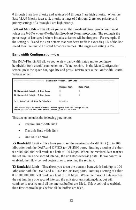
Bandwidth Configuration—bw
The iMcV-FiberLinX-II allows you to view bandwidth status and to configure bandwidth from a serial connection or a Telnet session. In the Main Configuration screen, press the space bar, type bw and press Enter to access the Bandwidth Control Settings screen:
------------------------- Bandwidth Control Settings ----------------------------- Optics Port Data Port
Bandwidth Limit, 0 For None 0 0 RX
Bandwidth Limit, 0 For None 0 0 TX
it RateControl Enable/Disable Disable Un
ge Value. Use Arrow Keys To Move Cursor. Press Space Bar To ChanPress RETURN To Set New Value. Press Q or F4 to Exit.
This screen includes the following parameters:
• Receive Bandwidth Limit
• Transmit Bandwidth Limit
• Unit Rate Control
RX Bandwidth Limit - This allows you to set the receive bandwidth limit (up to 100 Mbps) for both the DATA and OPTICS (or UPLINK) ports. Entering a setting of either 0 or 100,000,000 will result in a limit of 100 Mbps. When the received data reaches the set limit in a one second interval, the unit stops receiving data. If flow control is enabled, then flow control begins prior to reaching the set limit.
TX Bandwidth Limit – This allows you to set the transmit bandwidth limit (up to 100 Mbps) for both the DATA and OPTICS (or UPLINK) ports. Entering a setting of either 0 or 100,000,000 will result in a limit of 100 Mbps. When the transmit data reaches the set limit in a one second interval, the unit stops transmitting data, but will continue to receive until all the internal buffers are filled. If flow control is enabled, then flow control begins before all the buffers are filled.
32
NOTE
It is not recommended to set both the RX and TX Bandwidth limits at the same time. Setting TX Bandwidth Limits allows for full use of the memory buffers in the unit.
Unit RateControl Enable/Disable –This allows you to enable/disable the bandwidth limiting feature on this unit.
VII - Application Overview
Before using iMcV-FiberLinX-II in your network, decide the following:
• Will iMcV-FiberLinX-II units be located at only one or at both ends of the fiber?
• How do you want to manage the iMcV-FiberLinX-II units?
• Will you define VLAN IDs?
How many iMcV-FiberLinX-II units will you use?
• Two for Host/Remote applications–allows IP-less management providing greater security
• One for a single unit application
How do you want to manage iMcV-FiberLinX-II?
You can manage iMcV-FiberLinX-II through any of its three ports (and any combination thereof) or from the chassis. Using the EXT MGMT/OPTICS (or UPLINK) port combination separates management traffic from the data and provides the highest level of security. UMA management does not require an IP address.
Will you define VLAN IDs?
When you want to use VLAN traffic with specific tags on any/all of the DATA ports, you will need to disable Transparency and define VLAN IDs (refer to VLAN Configuration section). When you want to use both VLAN tagged, untagged, or double-tagged traffic, enable Transparency.
33
VIII - Application Examples
The following are application examples of the different VLAN configuration modes available using the iMcV-FiberLinX-II. If you require assistance configuring an application, contact IMC Networks Technical Support at [email protected].
The application modes include the following:
• Default
• Transparent with Untagged Management
• Transparent with Tagged Management
• Transparent with Extra Tagging (Q-in-Q)
• Port VLAN
• Port VLAN Filter
NOTE
When configuring VLAN IDs, remember that you can use any VLAN ID between 1 and 4,094. The VLAN IDs used in the following applications are for example purposes ONLY.
Default
Default mode passes only untagged data between the DATA port and the OPTICS (or UPLINK) port. This mode is the factory default and is provided as a starting point from which to configure the iMcV-FiberLinX-II modules. It is not intended as a mode for normal use.
NOTE
Default Mode does not provide any management traffic protection and is not recommended for normal use.
Transparent with Untagged Management
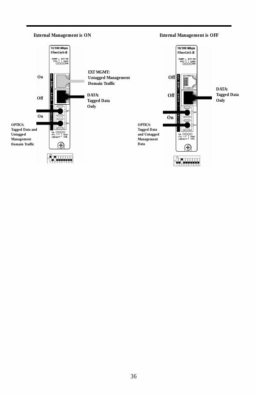
Transparent with Untagged Management mode passes tagged traffic between the DATA port and the OPTICS (or UPLINK) port and isolates untagged traffic as management domain traffic (untagged).
To configure this mode, do the following:
1. Set the management DIP switch ON for the ports using management (in this example it is the OPTICS (or UPLINK) port: 3 = ON). To enable External
34
Management (EXT MGMT), set DIP Switch 1 to ON. (otherwise, leave DIP Switch 1 in the OFF position (default from factory) to disable EXT MGMT)
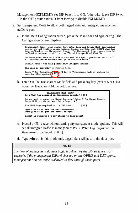
2. Set Transparent Mode to allow both tagged data and untagged management traffic to pass:
a. In the Main Configuration screen, press the space bar and type config. The Configuration Screen displays:
Transparent Mode – with either (not both) Data and Optics Mgmt dipswitchesset to on, all traffic passes between Optics and Data port EXCEPT what has been defined as the Management Domain. The Management Domain can either be efined as untagged traffic or traffic with a specified VLAN ID. d In Transparent Mode with BOTH Optics and Data Mgmt dipswitches set to off, ll traffic passes between the Optics and Data Ports. a efault Mode – the unit passes only Untagged Packets. D he unit is currently in Default Mode. T Enter Y for Transparent Mode, N for no Transparent Mode or <enter> to move to other options [ Y ]
b. Enter Y in the Transparent Mode field and press any key (except S or Q) to open the Transparent Mode Setup screen.
TRANSPARENT MODE SETUPIs a VLAN tag required on Management packets? [ N ]
er Y for Extra Tagging. Do you want to enter the Extra Tag mode? Entnter N if you do not want Extra Tags [ N ] E re VLAN Tags required on the EXT Port? [ N ] A
Type S or F3 to save the new informationype Q of F4 to quit and cancel changes T Reboot is required for any change to take affect.
c. Press S or F3 to save without setting any transparent mode options. This will set all untagged traffic as management (Is a VLAN tag required on Management packets? [ N ]).
d. Type reboot. In this mode only tagged data will pass to the data port.
NOTE
The flow of management domain traffic is defined by the DIP switches. For example, if the management DIP switches are on the OPTICS and DATA ports, management domain traffic is allowed to flow through those ports.
35
Off
Off
On
DATA:Tagged Data Only
OPTICS: Tagged Data and Untagged Management Data
External Management is OFF
On
Off
On
DATA:Tagged Data Only
OPTICS: Tagged Data and Untagged Management Domain Traffic
EXT MGMT:Untagged Management Domain Traffic
External Management is ON
36
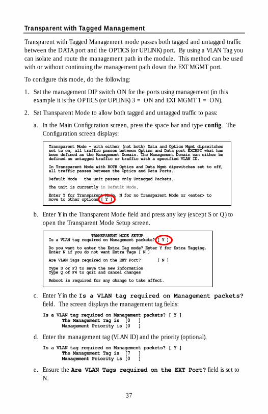
Transparent with Tagged Management
Transparent with Tagged Management mode passes both tagged and untagged traffic between the DATA port and the OPTICS (or UPLINK) port. By using a VLAN Tag you can isolate and route the management path in the module. This method can be used with or without continuing the management path down the EXT MGMT port.
To configure this mode, do the following:
1. Set the management DIP switch ON for the ports using management (in this example it is the OPTICS (or UPLINK) 3 = ON and EXT MGMT 1 = ON).
2. Set Transparent Mode to allow both tagged and untagged traffic to pass:
a. In the Main Configuration screen, press the space bar and type config. The Configuration screen displays:
b. Enter Y in the Transparent Mode field and press any key (except S or Q) to open the Transparent Mode Setup screen.
TRANSPARENT MODE SETUPIs a VLAN tag required on Management packets? [ Y ]
er Y for Extra Tagging. Do you want to enter the Extra Tag mode? Entnter N if you do not want Extra Tags [ N ] E re VLAN Tags required on the EXT Port? [ N ] A
Type S or F3 to save the new informationype Q of F4 to quit and cancel changes T Reboot is required for any change to take affect.
Transparent Mode – with either (not both) Data and Optics Mgmt dipswitchesset to on, all traffic passes between Optics and Data port EXCEPT what has been defined as the Management Domain. The Management Domain can either be efined as untagged traffic or traffic with a specified VLAN ID. d In Transparent Mode with BOTH Optics and Data Mgmt dipswitches set to off, ll traffic passes between the Optics and Data Ports. a efault Mode – the unit passes only Untagged Packets. D he unit is currently in Default Mode. T Enter Y for Transparent Mode, N for no Transparent Mode or <enter> to move to other options [ Y ]
c. Enter Y in the Is a VLAN tag required on Management packets? field. The screen displays the management tag fields: Is a VLAN tag required on Management packets? [ Y ] The Management Tag is [0 ] Management Priority is [0 ]
d. Enter the management tag (VLAN ID) and the priority (optional). Is a VLAN tag required on Management packets? [ Y ] The Management Tag is [7 ] Management Priority is [0 ]
e. Ensure the Are VLAN Tags required on the EXT Port? field is set to N.
37
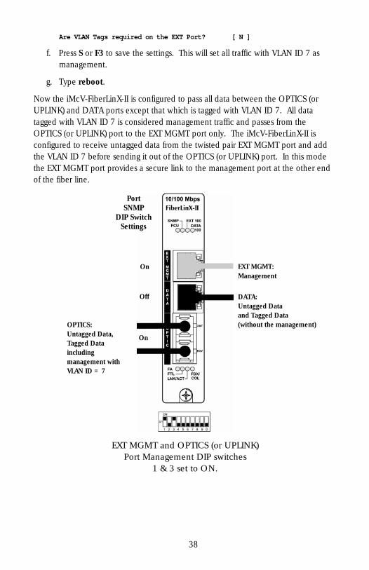
Are VLAN Tags required on the EXT Port? [ N ]
f. Press S or F3 to save the settings. This will set all traffic with VLAN ID 7 as management.
g. Type reboot.
Now the iMcV-FiberLinX-II is configured to pass all data between the OPTICS (or UPLINK) and DATA ports except that which is tagged with VLAN ID 7. All data tagged with VLAN ID 7 is considered management traffic and passes from the OPTICS (or UPLINK) port to the EXT MGMT port only. The iMcV-FiberLinX-II is configured to receive untagged data from the twisted pair EXT MGMT port and add the VLAN ID 7 before sending it out of the OPTICS (or UPLINK) port. In this mode the EXT MGMT port provides a secure link to the management port at the other end of the fiber line.
On
Off
On
PortSNMP
DIP SwitchSettings
DATA:Untagged Data and Tagged Data (without the management) OPTICS:
Untagged Data, Tagged Data including management with VLAN ID = 7
EXT MGMT:Management
EXT MGMT and OPTICS (or UPLINK) Port Management DIP switches
1 & 3 set to ON.
38
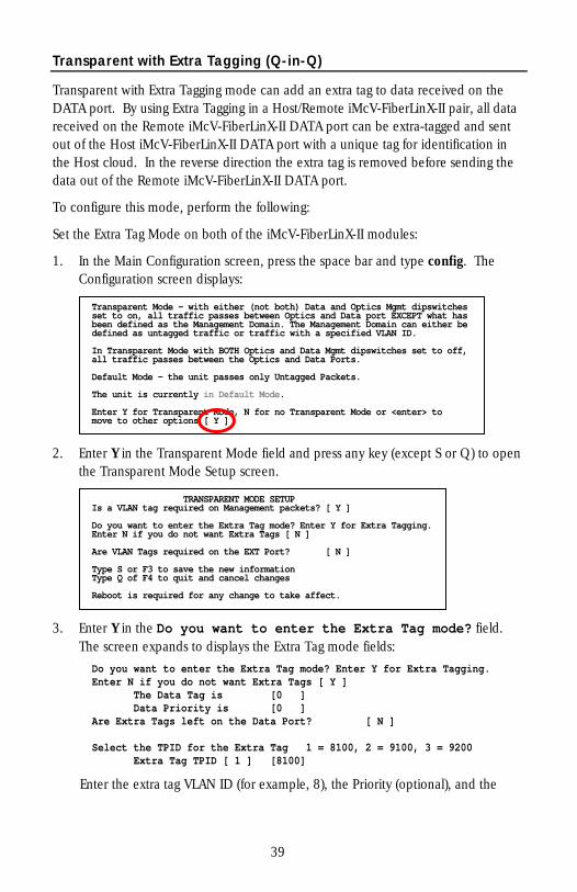
Transparent with Extra Tagging (Q-in-Q)
Transparent with Extra Tagging mode can add an extra tag to data received on the DATA port. By using Extra Tagging in a Host/Remote iMcV-FiberLinX-II pair, all data received on the Remote iMcV-FiberLinX-II DATA port can be extra-tagged and sent out of the Host iMcV-FiberLinX-II DATA port with a unique tag for identification in the Host cloud. In the reverse direction the extra tag is removed before sending the data out of the Remote iMcV-FiberLinX-II DATA port.
To configure this mode, perform the following:
Set the Extra Tag Mode on both of the iMcV-FiberLinX-II modules:
1. In the Main Configuration screen, press the space bar and type config. The Configuration screen displays:
Transparent Mode – with either (not both) Data and Optics Mgmt dipswitchesset to on, all traffic passes between Optics and Data port EXCEPT what has been defined as the Management Domain. The Management Domain can either be efined as untagged traffic or traffic with a specified VLAN ID. d In Transparent Mode with BOTH Optics and Data Mgmt dipswitches set to off, ll traffic passes between the Optics and Data Ports. a efault Mode – the unit passes only Untagged Packets. D he unit is currently in Default Mode. T Enter Y for Transparent Mode, N for no Transparent Mode or <enter> to move to other options [ Y ]
2. Enter Y in the Transparent Mode field and press any key (except S or Q) to open the Transparent Mode Setup screen.
TRANSPARENT MODE SETUPIs a VLAN tag required on Management packets? [ Y ]
er Y for Extra Tagging. Do you want to enter the Extra Tag mode? Entnter N if you do not want Extra Tags [ N ] E re VLAN Tags required on the EXT Port? [ N ] A
Type S or F3 to save the new informationype Q of F4 to quit and cancel changes T Reboot is required for any change to take affect.
3. Enter Y in the Do you want to enter the Extra Tag mode? field. The screen expands to displays the Extra Tag mode fields:
Do you want to enter the Extra Tag mode? Enter Y for Extra Tagging. Enter N if you do not want Extra Tags [ Y ] The Data Tag is [0 ] Data Priority is [0 ] Are Extra Tags left on the Data Port? [ N ] Select the TPID for the Extra Tag 1 = 8100, 2 = 9100, 3 = 9200 Extra Tag TPID [ 1 ] [8100]
Enter the extra tag VLAN ID (for example, 8), the Priority (optional), and the
39

EtherType (optional). These values must be identical on both iMcV-FiberLinX-II modules.
The Data Tag is [8 ] Data Priority is [0 ] Are Extra Tags left on the Data Port? [ N ] Select the TPID for the Extra Tag 1 = 8100, 2 = 9100, 3 = 9200 Extra Tag TPID [ 1 ] [8100]
4. On the Host iMcV-FiberLinX-II module, enter Y in the Are Extra Tags left on the Data Port? field to only accept the Extra Tag VLAN ID on the DATA port. On the Remote iMcV-FiberLinX-II module, enter N to have the Extra Tag VLAN ID added to incoming and removed from outgoing data on the DATA port.
5. Select the Extra Tag TPID EtherType (optional).
6. Press S or F3 to save the settings.
7. Type reboot. Repeat steps for second module.
Now the iMcV-FiberLinX-II Host/Remote pair is configured to pass only VLAN ID 8 data from the Host iMcV-FiberLinX-II to the Remote iMcV-FiberLinX-II where the VLAN ID 8 tag is removed before sending the data out of the Remote DATA port. The Extra Tag VLAN ID 8 is added to all data received on the Remote DATA port before being sent to the Host iMcV-FiberLinX-II where the VLAN ID 8 tag remains on the data leaving the Host DATA port.
40
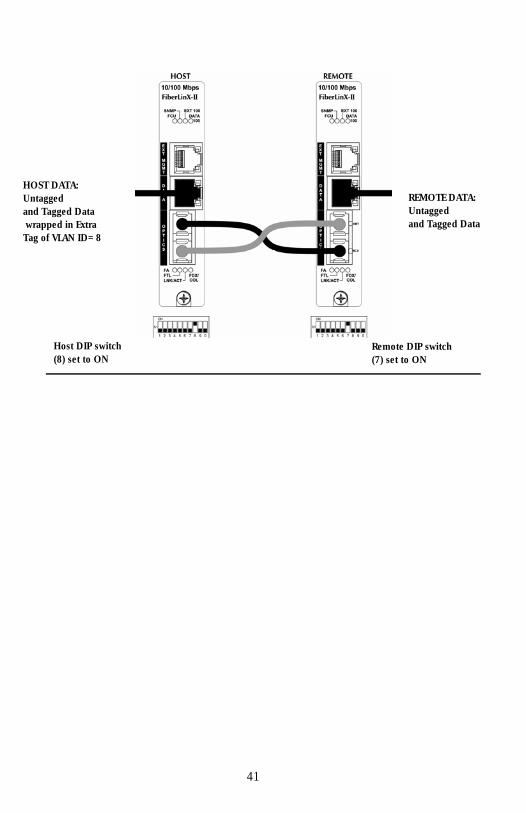
HOST DATA: Untagged REMOTE DATA:
Untagged and Tagged Data
and Tagged Data wrapped in Extra Tag of VLAN ID=8
Host DIP switch (8) set to ON
Remote DIP switch (7) set to ON
41
Port VLAN
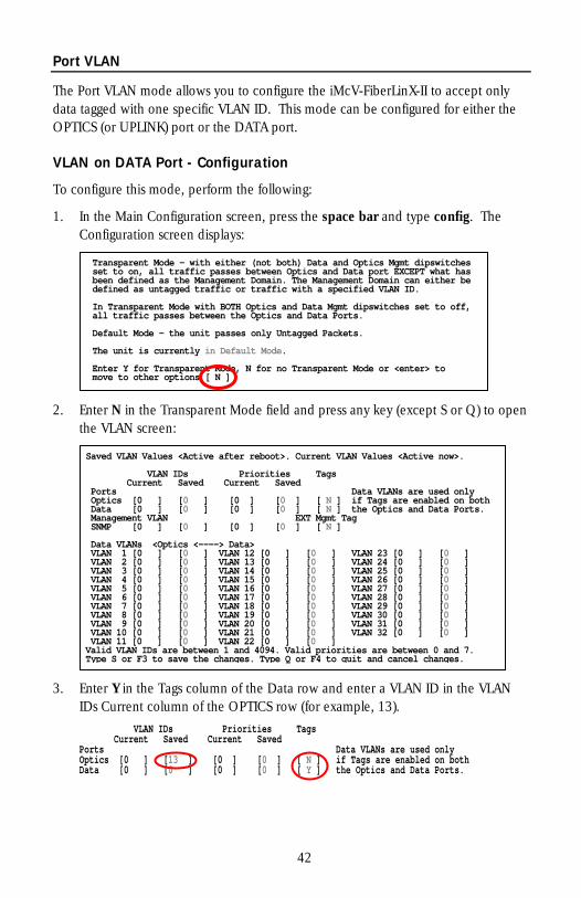
The Port VLAN mode allows you to configure the iMcV-FiberLinX-II to accept only data tagged with one specific VLAN ID. This mode can be configured for either the OPTICS (or UPLINK) port or the DATA port.
VLAN on DATA Port - Configuration
To configure this mode, perform the following:
1. In the Main Configuration screen, press the space bar and type config. The Configuration screen displays:
2. Enter N in the Transparent Mode field and press any key (except S or Q) to open the VLAN screen:
3. Enter Y in the Tags column of the Data row and enter a VLAN ID in the VLAN IDs Current column of the OPTICS row (for example, 13). VLAN IDs Priorities Tags Current Saved Current Saved Ports Data VLANs are used only
Optics [0 ] [13 ] [0 ] [0 ] [ N ] if Tags are enabled on bothData [0 ] [0 ] [0 ] [0 ] [ Y ] the Optics and Data Ports.
Saved VLAN Values <Active after reboot>. Current VLAN Values <Active now>.
Tags VLAN IDs Priorities Current Saved Current Saved Ports Data VLANs are used only
Optics [0 ] [0 ] [0 ] [0 ] [ N ] if Tags are enabled on both Optics and Data Ports. Data [0 ] [0 ] [0 ] [0 ] [ N ] the Management VLAN EXT Mgmt Tag
NMP [0 ] [0 ] [0 ] [0 ] [ N ] S Data VLANs <Optics <----> Data> VLAN 1 [0 ] [0 ] VLAN 12 [0 ] [0 ] VLAN 23 [0 ] [0 ] VLAN 2 [0 ] [0 ] VLAN 13 [0 ] [0 ] VLAN 24 [0 ] [0 ] VLAN 3 [0 ] [0 ] VLAN 14 [0 ] [0 ] VLAN 25 [0 ] [0 ] VLAN 4 [0 ] [0 ] VLAN 15 [0 ] [0 ] VLAN 26 [0 ] [0 ] VLAN 5 [0 ] [0 ] VLAN 16 [0 ] [0 ] VLAN 27 [0 ] [0 ] VLAN 6 [0 ] [0 ] VLAN 17 [0 ] [0 ] VLAN 28 [0 ] [0 ] VLAN 7 [0 ] [0 ] VLAN 18 [0 ] [0 ] VLAN 29 [0 ] [0 ] VLAN 8 [0 ] [0 ] VLAN 19 [0 ] [0 ] VLAN 30 [0 ] [0 ] VLAN 9 [0 ] [0 ] VLAN 20 [0 ] [0 ] VLAN 31 [0 ] [0 ]
VLAN 32 [0 ] [0 ] VLAN 10 [0 ] [0 ] VLAN 21 [0 ] [0 ] VLAN 11 [0 ] [0 ] VLAN 22 [0 ] [0 ]
7. Valid VLAN IDs are between 1 and 4094. Valid priorities are between 0 and Type S or F3 to save the changes. Type Q or F4 to quit and cancel changes.
Transparent Mode – with either (not both) Data and Optics Mgmt dipswitchesset to on, all traffic passes between Optics and Data port EXCEPT what has been defined as the Management Domain. The Management Domain can either be efined as untagged traffic or traffic with a specified VLAN ID. d In Transparent Mode with BOTH Optics and Data Mgmt dipswitches set to off, ll traffic passes between the Optics and Data Ports. a efault Mode – the unit passes only Untagged Packets. D he unit is currently in Default Mode. T Enter Y for Transparent Mode, N for no Transparent Mode or <enter> to move to other options [ N ]
42
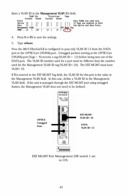
Enter a VLAN ID in the Management VLAN IDs field. VLAN IDs Priorities Tags Current Saved Current Saved Ports Data VLANs are used only
Optics [0 ] [13 ] [0 ] [0 ] [ N ] if Tags are enabled on bothhe Optics and Data Ports. Data [0 ] [0 ] [0 ] [0 ] [ Y ] t
Management VLAN.........................EXT Mgmt Tag NMP....[0 ] [20 ] [0 ] [0 ] [ Y ] S
4. Press S or F3 to save the settings.
5. Type reboot.
Now the iMcV-FiberLinX-II is configured to pass only VLAN ID 13 from the DATA port to the OPTICS (or UPLINK) port. Untagged packets arriving at the OPTICS (or UPLINK) port (Tags = N) receive a tag (VLAN ID = 13) before being sent out of the DATA port. The VLAN ID number used for a port must be different than the number used for the Management VLAN ID tag (VLAN ID=20). The EXT MGMT must have VLAN=20.
If Y is entered in the EXT MGMT Tag field, the VLAN ID for this port is the value in the Management VLAN field. In this case, define a VLAN ID in the Management VLAN field. If the unit is managed through the EXT MGMT port using untagged frames, the Management VLAN does not need to be defined.
EXT MGMTVLAN ID=20
OPTICS:Untagged
DATA:Data VLAN ID=13
EXT MGMT Port Management DIP switch 1 set to ON.
43
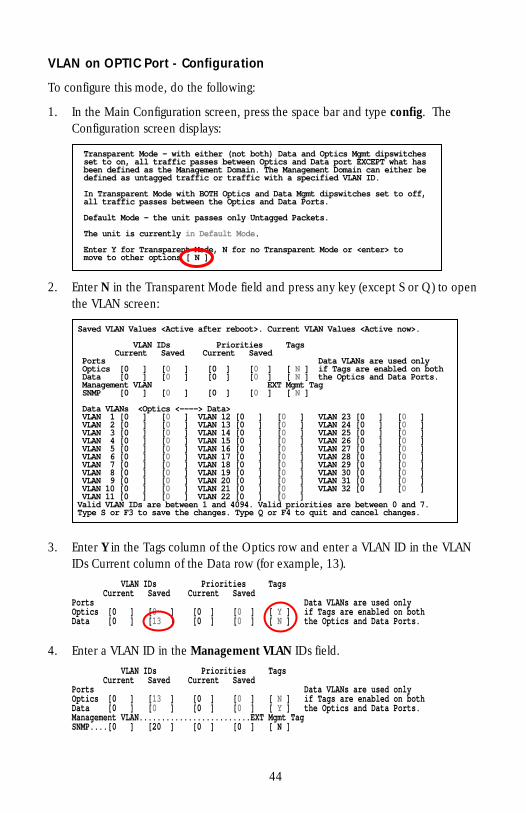
VLAN on OPTIC Port - Configuration
To configure this mode, do the following:
1. In the Main Configuration screen, press the space bar and type config. The Configuration screen displays:
2. Enter N in the Transparent Mode field and press any key (except S or Q) to open the VLAN screen:
3. Enter Y in the Tags column of the Optics row and enter a VLAN ID in the VLAN IDs Current column of the Data row (for example, 13). VLAN IDs Priorities Tags Current Saved Current Saved Ports Data VLANs are used only
Optics [0 ] [0 ] [0 ] [0 ] [ Y ] if Tags are enabled on bothData [0 ] [13 ] [0 ] [0 ] [ N ] the Optics and Data Ports.
Saved VLAN Values <Active after reboot>. Current VLAN Values <Active now>.
Tags VLAN IDs Priorities Current Saved Current Saved Ports Data VLANs are used only
Optics [0 ] [0 ] [0 ] [0 ] [ N ] if Tags are enabled on both Optics and Data Ports. Data [0 ] [0 ] [0 ] [0 ] [ N ] the Management VLAN EXT Mgmt Tag
NMP [0 ] [0 ] [0 ] [0 ] [ N ] S Data VLANs <Optics <----> Data> VLAN 1 [0 ] [0 ] VLAN 12 [0 ] [0 ] VLAN 23 [0 ] [0 ] VLAN 2 [0 ] [0 ] VLAN 13 [0 ] [0 ] VLAN 24 [0 ] [0 ] VLAN 3 [0 ] [0 ] VLAN 14 [0 ] [0 ] VLAN 25 [0 ] [0 ] VLAN 4 [0 ] [0 ] VLAN 15 [0 ] [0 ] VLAN 26 [0 ] [0 ] VLAN 5 [0 ] [0 ] VLAN 16 [0 ] [0 ] VLAN 27 [0 ] [0 ] VLAN 6 [0 ] [0 ] VLAN 17 [0 ] [0 ] VLAN 28 [0 ] [0 ] VLAN 7 [0 ] [0 ] VLAN 18 [0 ] [0 ] VLAN 29 [0 ] [0 ] VLAN 8 [0 ] [0 ] VLAN 19 [0 ] [0 ] VLAN 30 [0 ] [0 ] VLAN 9 [0 ] [0 ] VLAN 20 [0 ] [0 ] VLAN 31 [0 ] [0 ]
VLAN 32 [0 ] [0 ] VLAN 10 [0 ] [0 ] VLAN 21 [0 ] [0 ] VLAN 11 [0 ] [0 ] VLAN 22 [0 ] [0 ]
7. Valid VLAN IDs are between 1 and 4094. Valid priorities are between 0 and Type S or F3 to save the changes. Type Q or F4 to quit and cancel changes.
Transparent Mode – with either (not both) Data and Optics Mgmt dipswitchesset to on, all traffic passes between Optics and Data port EXCEPT what has been defined as the Management Domain. The Management Domain can either be efined as untagged traffic or traffic with a specified VLAN ID. d In Transparent Mode with BOTH Optics and Data Mgmt dipswitches set to off, ll traffic passes between the Optics and Data Ports. a efault Mode – the unit passes only Untagged Packets. D he unit is currently in Default Mode. T Enter Y for Transparent Mode, N for no Transparent Mode or <enter> to move to other options [ N ]
4. Enter a VLAN ID in the Management VLAN IDs field. VLAN IDs Priorities Tags Current Saved Current Saved Ports Data VLANs are used only
Optics [0 ] [13 ] [0 ] [0 ] [ N ] if Tags are enabled on bothhe Optics and Data Ports. Data [0 ] [0 ] [0 ] [0 ] [ Y ] t
Management VLAN.........................EXT Mgmt Tag NMP....[0 ] [20 ] [0 ] [0 ] [ N ] S
44
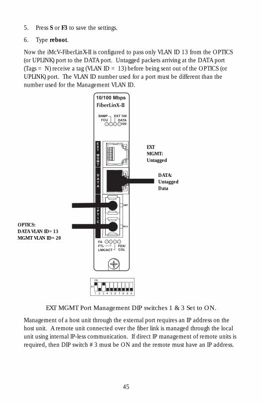
5. Press S or F3 to save the settings.
6. Type reboot.
Now the iMcV-FiberLinX-II is configured to pass only VLAN ID 13 from the OPTICS (or UPLINK) port to the DATA port. Untagged packets arriving at the DATA port (Tags = N) receive a tag (VLAN ID = 13) before being sent out of the OPTICS (or UPLINK) port. The VLAN ID number used for a port must be different than the number used for the Management VLAN ID.
EXT MGMT: Untagged
DATA:Untagged Data
OPTICS: DATA VLAN ID=13 MGMT VLAN ID=20
EXT MGMT Port Management DIP switches 1 & 3 Set to ON.
Management of a host unit through the external port requires an IP address on the host unit. A remote unit connected over the fiber link is managed through the local unit using internal IP-less communication. If direct IP management of remote units is required, then DIP switch #3 must be ON and the remote must have an IP address.
45
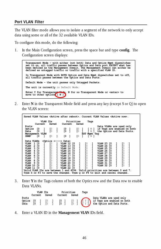
Port VLAN Filter
The VLAN filter mode allows you to isolate a segment of the network to only accept data using some or all of the 32 available VLAN IDs.
To configure this mode, do the following:
1. In the Main Configuration screen, press the space bar and type config. The Configuration screen displays:
Transparent Mode – with either (not both) Data and Optics Mgmt dipswitchesset to on, all traffic passes between Optics and Data port EXCEPT what has been defined as the Management Domain. The Management Domain can either be efined as untagged traffic or traffic with a specified VLAN ID. d In Transparent Mode with BOTH Optics and Data Mgmt dipswitches set to off, ll traffic passes between the Optics and Data Ports. a efault Mode – the unit passes only Untagged Packets. D he unit is currently in Default Mode. T Enter Y for Transparent Mode, N for no Transparent Mode or <enter> to move to other options [ N ]
2. Enter N in the Transparent Mode field and press any key (except S or Q) to open the VLAN screen:
3. Enter Y in the Tags column of both the Optics row and the Data row to enable Data VLANs. VLAN IDs Priorities Tags Current Saved Current Saved Ports Data VLANs are used only
Optics [0 ] [0 ] [0 ] [0 ] [ Y ] if Tags are enabled on bothData [0 ] [0 ] [0 ] [0 ] [ Y ] the Optics and Data Ports.
4. Enter a VLAN ID in the Management VLAN IDs field.
Saved VLAN Values <Active after reboot>. Current VLAN Values <Active now>.
Tags VLAN IDs Priorities Current Saved Current Saved Ports Data VLANs are used only
Optics [0 ] [0 ] [0 ] [0 ] [ N ] if Tags are enabled on bothe Optics and Data Ports. Data [0 ] [0 ] [0 ] [0 ] [ N ] th
Management VLAN EXT Mgmt Tag NMP [0 ] [0 ] [0 ] [0 ] [ N ] S
Data VLANs <Optics <----> Data> VLAN 1 [0 ] [0 ] VLAN 12 [0 ] [0 ] VLAN 23 [0 ] [0 ] VLAN 2 [0 ] [0 ] VLAN 13 [0 ] [0 ] VLAN 24 [0 ] [0 ] VLAN 3 [0 ] [0 ] VLAN 14 [0 ] [0 ] VLAN 25 [0 ] [0 ] VLAN 4 [0 ] [0 ] VLAN 15 [0 ] [0 ] VLAN 26 [0 ] [0 ] VLAN 5 [0 ] [0 ] VLAN 16 [0 ] [0 ] VLAN 27 [0 ] [0 ] VLAN 6 [0 ] [0 ] VLAN 17 [0 ] [0 ] VLAN 28 [0 ] [0 ] VLAN 7 [0 ] [0 ] VLAN 18 [0 ] [0 ] VLAN 29 [0 ] [0 ] VLAN 8 [0 ] [0 ] VLAN 19 [0 ] [0 ] VLAN 30 [0 ] [0 ] VLAN 9 [0 ] [0 ] VLAN 20 [0 ] [0 ] VLAN 31 [0 ] [0 ]
VLAN 32 [0 ] [0 ] VLAN 10 [0 ] [0 ] VLAN 21 [0 ] [0 ] VLAN 11 [0 ] [0 ] VLAN 22 [0 ] [0 ]
7. Valid VLAN IDs are between 1 and 4094. Valid priorities are between 0 and Type S or F3 to save the changes. Type Q or F4 to quit and cancel changes.
46

Enter up to 32 VLAN IDs in the Data VLANs rows. VLAN IDs can range from 1 to 4094. Data VLANs <Optics <----> Data> VLAN 1 [0 ] [101 ] VLAN 12 [0 ] [112 ] VLAN 23 [0 ] [123 ] VLAN 2 [0 ] [102 ] VLAN 13 [0 ] [113 ] VLAN 24 [0 ] [124 ] VLAN 3 [0 ] [103 ] VLAN 14 [0 ] [114 ] VLAN 25 [0 ] [125 ] VLAN 4 [0 ] [104 ] VLAN 15 [0 ] [115 ] VLAN 26 [0 ] [126 ] VLAN 5 [0 ] [105 ] VLAN 16 [0 ] [116 ] VLAN 27 [0 ] [127 ] VLAN 6 [0 ] [106 ] VLAN 17 [0 ] [117 ] VLAN 28 [0 ] [128 ] VLAN 7 [0 ] [107 ] VLAN 18 [0 ] [118 ] VLAN 29 [0 ] [129 ] VLAN 8 [0 ] [108 ] VLAN 19 [0 ] [119 ] VLAN 30 [0 ] [130 ] VLAN 9 [0 ] [109 ] VLAN 20 [0 ] [120 ] VLAN 31 [0 ] [131 ] VLAN 10 [0 ] [110 ] VLAN 21 [0 ] [121 ] VLAN 32 [0 ] [132 ] VLAN 11 [0 ] [111 ] VLAN 22 [0 ] [122 ]
5. Press S or F3 to save the settings.
6. Type reboot.
47
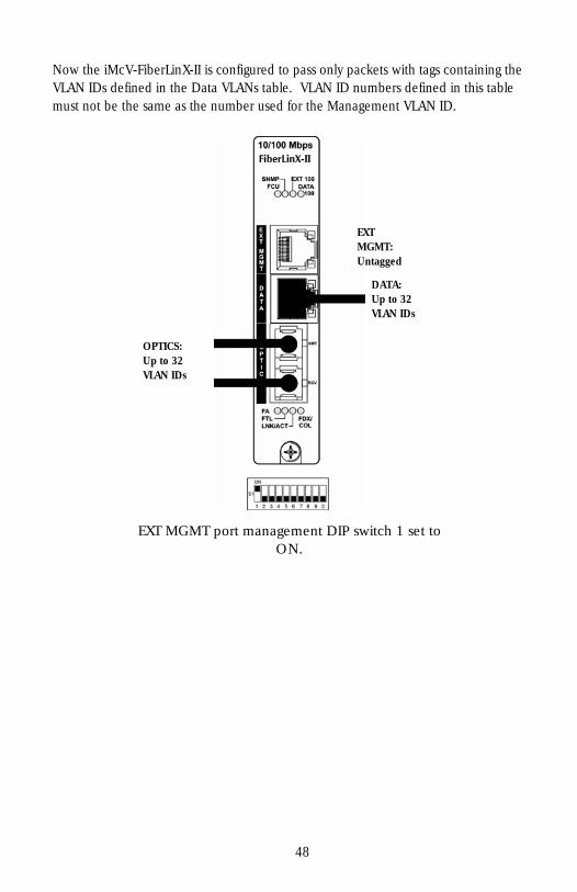
Now the iMcV-FiberLinX-II is configured to pass only packets with tags containing the VLAN IDs defined in the Data VLANs table. VLAN ID numbers defined in this table must not be the same as the number used for the Management VLAN ID.
EXT MGMT: Untagged
DATA:Up to 32 VLAN IDs
OPTICS:Up to 32 VLAN IDs
EXT MGMT port management DIP switch 1 set to ON.
48
IX - Troubleshooting
• If two iMcV-FiberLinX-II Host/Remote units are not communicating properly, make sure one is a Host and the other is a Remote. If the second unit is not configured as a Remote, it will be recognized as a Standalone unit and the Host and Remote units will not communicate with each other properly. Setting the OPTICS (or UPLINK) port management DIP switch #3 to the ON position on both modules will allow you to perform a simple ping test. This is possible only if pinging from the computer through the optics uplink port, which is highly unusual. You must enable the EXT or data switch and connect to the computer to ping either device.
• If you cannot establish a link on a twisted pair port, make sure the cable is in working order; if not, replace the cable (iMcV-FiberLinX-II includes AutoCross; you should detect a link regardless of the Cat5 cable type).
• If you cannot establish a fiber link, make sure that the fiber transceivers on iMcV-FiberLinX-II are not over/under driving the fiber receivers. For fiber specifications, please visit www.imcnetworks.com/support/fpblookup.cfm. Make sure the fiber mode and wavelength on both iMcV-FiberLinX-II units match (i.e., both are 1310 nm single-mode fiber).
• Make sure the port speeds on iMcV-FiberLinX-II match those on the end devices connected to iMcV-FiberLinX-II. IMC Networks recommends configuring all connected devices to Autonegotiation, or if using Force mode, ensure speed and duplex settings match.
• If using single-strand fiber, make sure the pair of devices is compatible single-strand fiber devices. For example, an iMcV-FiberLinX-II TX/SSFX-SM1310-SC which transmits 1310 nm and receives 1550 nm must be connected to a device which transmits 1550 nm and receives 1310 nm.
• If using an iMcV-FiberLinX-II unit with an SFP port and it is not functioning properly or at all, make sure that the installed SFP module is the correct speed (100 Mbps).
• When using the FiberAlert feature, make sure that FiberAlert is enabled on only one unit when connecting two iMcV-FiberLinX-II units, or when connecting an iMcV-FiberLinX-II to another IMC Networks media converter which includes the FiberAlert feature.
• If management is not functioning properly, make sure that the DIP switch settings are accurate for the port you want to manage.
49
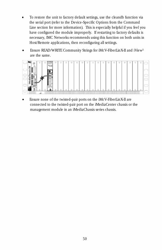
• To restore the unit to factory default settings, use the cleandb function via the serial port (refer to the Device-Specific Options from the Command Line section for more information). This is especially helpful if you feel you have configured the module improperly. If restarting to factory defaults is necessary, IMC Networks recommends using this function on both units in Host/Remote applications, then reconfiguring all settings.
• Ensure READ/WRITE Community Strings for iMcV-FiberLinX-II and iView² are the same.
• Ensure none of the twisted-pair ports on the iMcV-FiberLinX-II are connected to the twisted-pair port on the iMediaCenter chassis or the management module in an iMediaChassis series chassis.
50
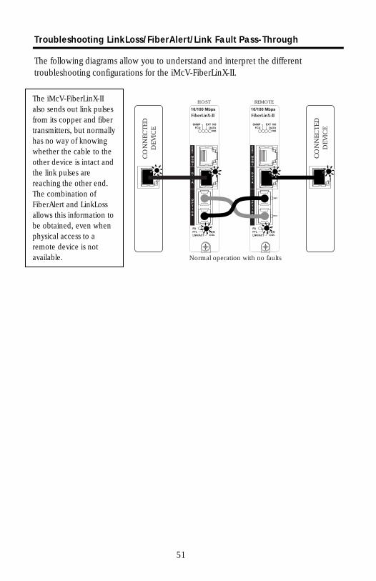
Troubleshooting LinkLoss/FiberAlert/Link Fault Pass-Through
The following diagrams allow you to understand and interpret the different troubleshooting configurations for the iMcV-FiberLinX-II.
HOST REMOTE
Normal operation with no faults
CO
NN
ECTE
DD
EVIC
E
CO
NN
ECTE
DD
EVIC
E
The iMcV-FiberLinX-II a so sends out link pulses f om its copper and fiber t ansmitters, but normally has no way of knowing whether the cable to the other device is intact and t e link pulses are r aching the other end. The combination of FiberAlert and LinkLoss allows this information to be obtained, even when physical access to a r mote device is not available.
lrr
he
e
51
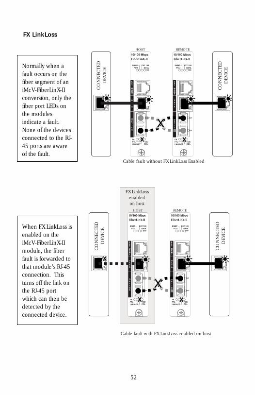
FX LinkLoss
HOST REMOTE
Cable fault without FX LinkLoss Enabled
XXXX
XX
CO
NN
ECTE
DD
EVIC
E
CO
NN
ECTE
DD
EVIC
E
Normally when a fault occurs on the f ber segment of an iMcV-FiberLinX-II conversion, only the fiber port LEDs on the modules i dicate a fault. None of the devices connected to the RJ-45 ports are aware of the fault.
i
n
HOST REMOTE
Cable fault with FX LinkLoss enabled on host
FX LinkLossenabledon host
XXXX
XX
XX
CO
NN
ECTE
DD
EVIC
E
CO
NN
ECTE
DD
EVIC
EWhen FX LinkLoss is enabled on the iMcV-FiberLinX-II module, the fiber fault is forwarded to that module’s RJ-45 connection. This turns off the link on the RJ-45 port which can then be detected by the connected device.
52
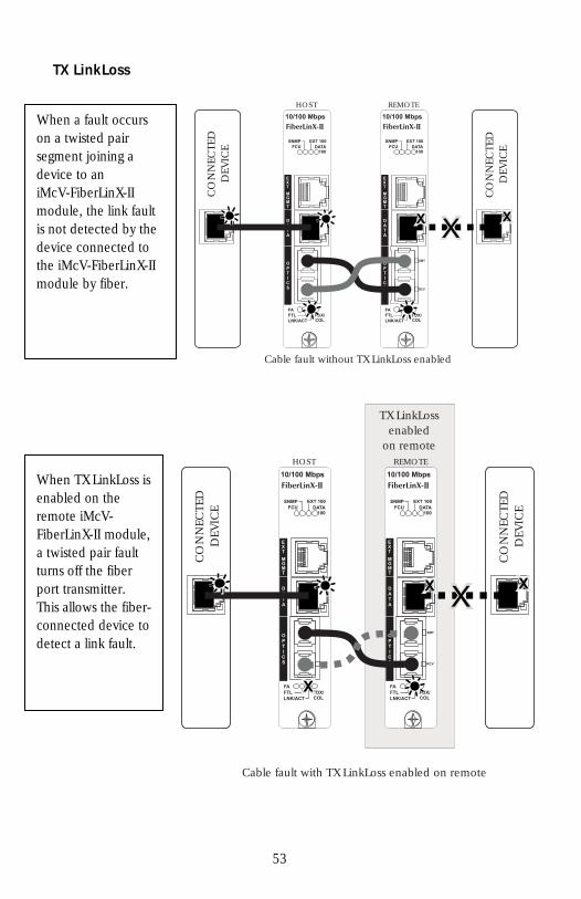
TX LinkLoss
HOST REMOTE
Cable fault without TX LinkLoss enabled
XX XXXX
CO
NN
ECTE
DD
EVIC
E
CO
NN
ECTE
DD
EVIC
E
When a fault occurs on a twisted pair segment joining a device to an iMcV-FiberLinX-II module, the link fault is not detected by the device connected to the iMcV-FiberLinX-II module by fiber.
TX LinkLossenabled
on remoteHOST REMOTE
Cable fault with TX LinkLoss enabled on remote
XX
XX XX
XX
CO
NN
ECTE
DD
EVIC
E
CO
NN
ECTE
DD
EVIC
E
When TX LinkLoss is enabled on the remote iMcV-FiberLinX-II module, a twisted pair fault turns off the fiber port transmitter. This allows the fiber-connected device to detect a link fault.
53
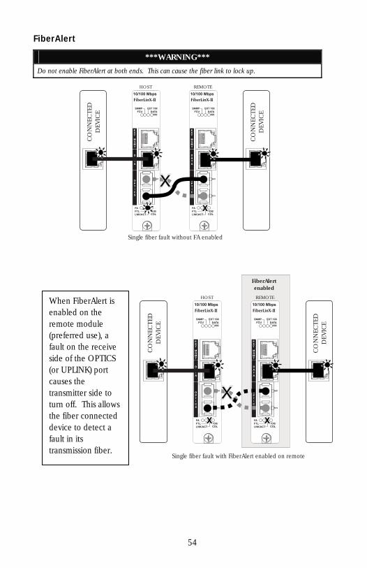
FiberAlert
***WARNING***
Do not enable FiberAlert at both ends. This can cause the fiber link to lock up.
HOST REMOTE
Single fiber fault without FA enabled
XX
XX
CO
NN
ECTE
DD
EVIC
E
CO
NN
ECTE
DD
EVIC
E
FiberAlertenabled
HOST REMOTE
Single fiber fault with FiberAlert enabled on remote
XXXX
XX
CO
NN
ECTE
DD
EVIC
E
CO
NN
ECTE
DD
EVIC
E
When FiberAlert is enabled on the remote module (preferred use), a fault on the receive side of the OPTICS (or UPLINK) port causes the transmitter side to turn off. This allows the fiber connected device to detect a fault in its transmission fiber.
54
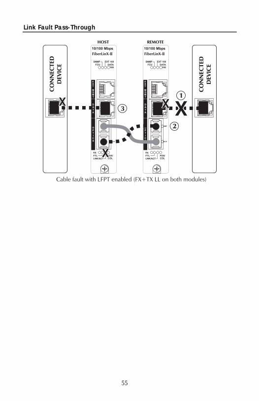
Link Fault Pass-Through
55

IMC Networks Technical Support
Tel: (949) 465-3000 or (800) 624-1070 (in the U.S. and Canada);
+32-16-550880 (Europe)
Fax: (949) 465-3020
E-Mail: [email protected]
Web: www.imcnetworks.com
Specifications
Power Consumption (Typical): 0.530 Amps @ 5 V
Operating Temperature: 32° to 122° F (0° to 50° C)
Storage Temperature: 0° to 160°F (-20° to 70° C)
Humidity: 5 to 95% (non-condensing); 0 to 10,000 ft. altitude
Dimensions: Single Slot iMcV module
Standards/Compliance
• Read/write IEEE 802.1Q VLAN tags • QoS IEEE 802.1p-based packet prioritization (2 queues [high/low] with 8 levels
of priority • IEEE 802.3x Flow Control • IEEE 802.3i 10Base-T twisted pair • IEEE 802.3u 100Base-TX twisted pair • IEEE 802.3u 100Base-FX or SX fiber
56
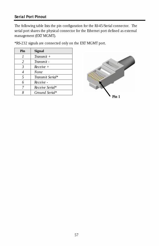
Serial Port Pinout
The following table lists the pin configuration for the RJ-45/Serial connector. The serial port shares the physical connector for the Ethernet port defined as external management (EXT MGMT).
*RS-232 signals are connected only on the EXT MGMT port.
Pin Signal
1 Transmit + 2 Transmit - 3 Receive + 4 None 5 Transmit Serial* 6 Receive - 7 Receive Serial* 8 Ground Serial*
Pin 1
57

Notes
58

Safety Certifications
UL/CUL: Listed to Safety of Information Technology Equipment, including Electrical Business Equipment.
CE: The products described herein comply with the Council Directive on Electromagnetic Compatibility (89/336/EEC) and the Council Directive on Electrical Equipment Designed for use within Certain Voltage Limits (73/23/EEC). Certified to Safety of Information Technology Equipment, Including Electrical Business Equipment. For further details, contact IMC Networks.
Class 1 Laser product, Luokan 1 Laserlaite, Laser Klasse 1, Appareil A’Laser de Classe 1
European Directive 2002/96/EC (WEEE) requires that any equipment that bears this symbol on product or packaging must not be disposed of with unsorted municipal waste. This symbol indicates that the equipment should be disposed of separately from regular household waste. It is the consumer’s responsibility to dispose of this and all equipment so marked through designated collection facilities appointed by government or local authorities. Following these steps through proper disposal and recycling will help prevent potential negative consequences to the environment and human health. For more detailed information about proper disposal, please contact local authorities, waste disposal services, or the point of purchase for this equipment.
59

19772 Pauling • Foothill Ranch, CA 92610-2611 USA TEL: (949) 465-3000 • FAX: (949) 465-3020
www.imcnetworks.com
© 2007 IMC Networks. All rights reserved. The information in this document is subject to change without notice. IMC Networks assumes no responsibility for any errors that may appear in this document. iMcV-FiberLinX-II is a trademark of IMC Networks. Other brands or product names may be trademarks and are the property of their respective companies.
Document Number 56-80011-01 A0 August 2007 If the product’s part number begins with an “8”, it is compliant with the Restriction of Hazardous Substances (RoHS) directive.