img47.chem17.comimg47.chem17.com/1/20181027/636762353907532049983.pdf · table of contents g3...
TRANSCRIPT

G3 | Communication Node and I/O580 | Communication Node
Fieldbus Electronics

Table of ContentsG3 Electronics
Features and Benefits 2G3 Platform Distribution Options 4CANopen® 6CC-Link IE Field™ 7DeviceNet™ 8EtherCAT® 9EtherNet/IP™ 10EtherNet/IP™ DLR 11Ethernet POWERLINK® 12Modbus® TCP/IP 13PROFIBUS™ DP 14PROFINET™ 15I/O Modules 16Input Modules - RTD & NAMUR IS 18Sub-bus Modules 19Miscellaneous Modules & Accessories 21G3 Dimensions 23G3 How To Order 25501 Series 29502 Series 32503 Series 352002 R2 & 02 Series 382005 Series 402012 Series 422035 Series 44ISO 15407-2 18mm Series 46ISO 15407-2 26mm Series 48ISO 5599/2 Series 50Power Cables & Connectors 52CANopen® and DeviceNet™ Cables & Connectors 55CC-Link IE Field™ Cables & Connectors 56EtherCAT® Cables & Connectors 57EtherNet/IP™, EtherNet/IP™ DLR and Modbus® TCP/IP Cables & Connectors 58Ethernet POWERLINK® Cables & Connectors 59PROFIBUS™ DP Cables & Connectors 60PROFINET™ Cables & Connectors 61I/O Cables & Connectors 62M23 19 Pin Cables & Connectors 65Sub-bus Cables & Connectors 66
580 SeriesFeatures and Benefits 68CANopen® 69DeviceNet™ 70EtherCAT® 71EtherNet/IP™ 72EtherNet/IP™ DLR 73Ethernet POWERLINK® 74IO-Link® 75PROFIBUS™ DP 76PROFINET™ 77580 CHARM Node 78580 Dimensions 79580 How to Order 80Power and Communication Cables & Connectors 82

2
ASCO NUMATICS™
Visit our website at ASCO.com or contact us at (800) 972-2726
G3 ELECTRONICS
Modbus is a registered trademark of Modbus Organization, Inc. EtherNet/IP, DeviceNet and QuickConnect are trademarks of ODVA.
EtherCAT is a registered trademark of the EtherCAT Technology Group. CANopen is a registered Community trademark of CAN in Automation e.V.
PROFIBUS and PROFINET are trademarks of Profibus Nutzerorganisation e.V. Ethernet POWERLINK is a registered trademark of Bernecker + Rainer Industrie – Elektronik Ges.m.b.H.
CC-Link is a registered trademark and CC-Link IE Field is a trademark of the CC-Link Partner Association.
*
Easy, Robust ConnectionsHighly Distributable
Auto Recovery ModuleGraphic Display forConfiguration & Diagnostics
• 1/2 turn for faster I/O connections• Backwards compatible with standard
M12 cables/connectors• Meets the same IP/NEMA standards
as M12/Micro cables/connectors• Same cost as standard M12/Micro
cables/connectors• See page 107 for cables with
SPEEDCON® connector technology
*Numatics I/O with SPEEDCON® Technology
Supported Protocols• CANopen®
• CC-Link IE Field™• DeviceNet™• DeviceNet™ w/
QuickConnect™ • EtherCAT®
• EtherNet/IP™
• EtherNet/IP™ DLR w/ QuickConnect™
• Ethernet POWERLINK®
• Modbus® TCP/IP • PROFIBUS™ DP• PROFINET™
G3 Fieldbus Communications ElectronicsWhy use Numatics Fieldbus communication electronics? Modular Reality...No internal wiring simplifies assembly• SPEEDCON® M12 connector technology allows for fast and
efficient ½ turn I/O connector attachment• Power connector allows output power to be removed while
inputs and communication are left active• IP65 protection• Up to 1,200 Input/1,200 Output capability with one
communication node!• Up to 128 valve solenoids per manifold, up to 17 manifolds
per communication node!• One node supports 16 I/O modules – Analog I/O, Digital I/O
(NPN & PNP) and Specialty• Integrated web server with EtherCAT® , EtherNet/IP™ ,
EtherNet/IP™ DLR, Ethernet POWERLINK®, Modbus® TCP/IP, and PROFINET™
• Innovative clip design allows easy module removal/replacement without dismantling manifold
• Auto Recovery Module (ARM) protects configuration information during a critical failure. Allows configuration information to be saved and reloaded to replacement module automatically
Commissioning Capabilities• Set network address (including
IP & Subnet mask for Ethernet)• Set baud rate• Set auto or manual I/O sizes• Set fault/idle output states• Set brightness• Set factory defaults• Visual diagnostics
• Shorted and open load detection
• Shorted sensor/cable detection• Low & missing power detection• Missing module detection• Self-test activation• Log of network errors• Distribution errors
G3 Fieldbus - Electronics Made Easy!Innovative Graphic Display is used for easy commissioning, visual status & diagnostics.
3
ASCO NUMATICS™
Visit our website at ASCO.com or contact us at (800) 972-2726
G3ELECTRONICS
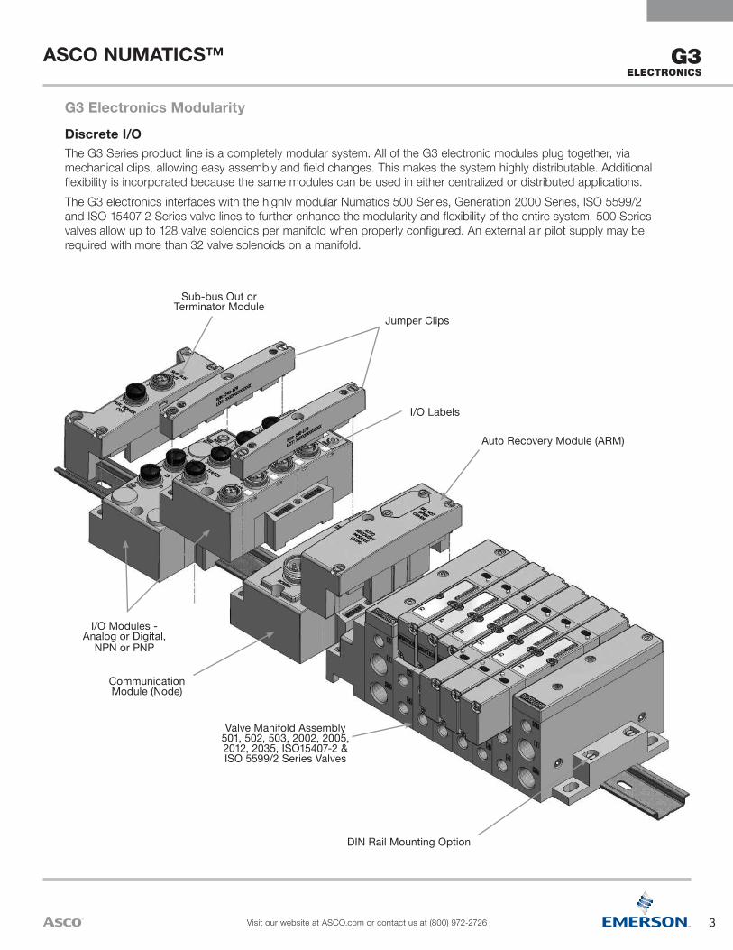
DIN Rail Mounting Option
Valve Manifold Assembly501, 502, 503, 2002, 2005, 2012, 2035, ISO15407-2 & ISO 5599/2 Series Valves
Communication Module (Node)
I/O Modules - Analog or Digital,
NPN or PNP
Auto Recovery Module (ARM)
I/O Labels
Jumper Clips
Sub-bus Out or Terminator Module
Discrete I/OThe G3 Series product line is a completely modular system. All of the G3 electronic modules plug together, via mechanical clips, allowing easy assembly and field changes. This makes the system highly distributable. Additional flexibility is incorporated because the same modules can be used in either centralized or distributed applications.The G3 electronics interfaces with the highly modular Numatics 500 Series, Generation 2000 Series, ISO 5599/2 and ISO 15407-2 Series valve lines to further enhance the modularity and flexibility of the entire system. 500 Series valves allow up to 128 valve solenoids per manifold when properly configured. An external air pilot supply may be required with more than 32 valve solenoids on a manifold.
G3 Electronics Modularity

4
ASCO NUMATICS™
Visit our website at ASCO.com or contact us at (800) 972-2726
G3 ELECTRONICS
24 VDC Power Supply
Sub-bus Manifold with I/O & Valves
Sub-bus
24 VDC Power Supply
Sub-bus Out
Sub-bus Manifold with Valves
Optional 24 VDC AUX Power
Sub-bus Out Sub-bus In
I/O Only
Sub-bus
Main Fieldbus Manifold
• Unique distribution system allows system efficiency by allowing the same modules to be used in either centralized or distributed applications
• Distribution options include: Inputs OR Outputs Inputs AND Outputs Valves with Inputs AND Outputs Valves with Inputs OR Outputs Valves Only
• Maximum Sub-bus length not to exceed 30 meters. Maximum Sub-bus cable current not to exceed 4 amps or excessive cable voltage drops per segment. Auxiliary power connections available for currents above 4 amps. Consult factory for possible deviations
G3 Platform Distribution OptionsEasy, Cost Effective Solutions for Digital I/O and Valve Automation using G3 Electronics.
5
ASCO NUMATICS™
Visit our website at ASCO.com or contact us at (800) 972-2726
G3ELECTRONICS
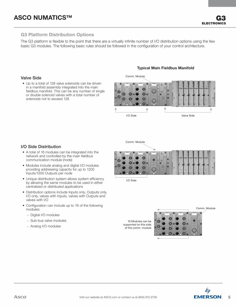
16 Modules can be supported on this side
of the comm. module
Comm. Module
I/O Side
Comm. Module
I/O Side Distribution• A total of 16 modules can be integrated into the
network and controlled by the main fieldbus communication module (node)
• Modules include analog and digital I/O modules providing addressing capacity for up to 1200 Inputs/1200 Outputs per node
• Unique distribution system allows system efficiency by allowing the same modules to be used in either centralized or distributed applications
• Distribution options include Inputs only, Outputs only, I/O only, valves with Inputs, valves with Outputs and valves with I/O
• Configuration can include up to 16 of the following modules:
– Digital I/O modules – Sub-bus valve modules – Analog I/O modules
Valve SideI/O Side
Comm. Module
Typical Main Fieldbus Manifold
Valve Side• Up to a total of 128 valve solenoids can be driven
in a manifold assembly integrated into the main fieldbus manifold. This can be any number of single or double solenoid valves with a total number of solenoids not to exceed 128
G3 Platform Distribution OptionsThe G3 platform is flexible to the point that there are a virtually infinite number of I/O distribution options using the few basic G3 modules. The following basic rules should be followed in the configuration of your control architecture.
6
ASCO NUMATICS™
Visit our website at ASCO.com or contact us at (800) 972-2726
G3 ELECTRONICS
WeightCANopen® Communications Module 252g/8.9 oz
Network DataSupported Baud Rates 125K Baud, 250K Baud, 500K Baud, 1M BaudBus Connector Single key 5 Pin 7/8” MINI type (male)Diagnostics Power, short, open load conditions and module health are monitored and fail-safe device settings
Configuration DataGraphic Display Display used for setting Node Address, Baud Rate, Fault/Idle Actions, and all other system settings
ARM (Auto Recovery Module) Optional module that contains automatic recovery of system setting in the event of total or partial system failure
Maximum Valve-Solenoid Outputs 32Maximum Addressable I/O Points Various combinations of 1200 outputs and 1200 inputs
Operating DataTemperature Range (ambient) -23 °C to 46 °C (-10 °F to 115 °F)Humidity 95% relative humidity, non-condensingVibration/Shock IEC 60068-2-27, IEC60068-2-6Moisture Protection IP65 (with appropriate assembly and termination)
Electrical Data Voltage CurrentNode Power at Max. Brightness 24 VDC +/- 10% 0.0404 AmpsBus Power 11 – 25 VDC 0.025 AmpsValves & Discrete I/O 24 VDC +/- 10% 8 Amps MaximumPower Connector Single key 4 Pin 7/8” MINI type (male)Communication Connector Single key 5 Pin 7/8” MINI type (male)LEDs Module Status and Network Status
Technical Data
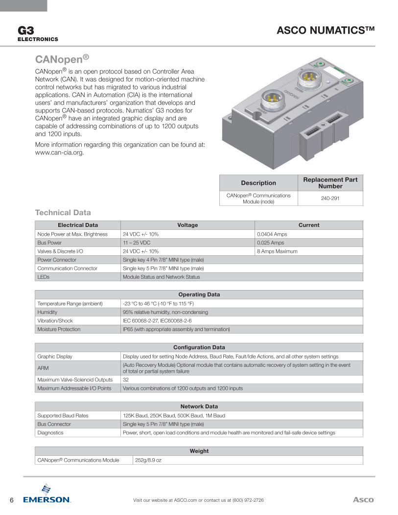
CANopen®
CANopen® is an open protocol based on Controller Area Network (CAN). It was designed for motion-oriented machine control networks but has migrated to various industrial applications. CAN in Automation (CIA) is the international users’ and manufacturers’ organization that develops and supports CAN-based protocols. Numatics’ G3 nodes for CANopen® have an integrated graphic display and are capable of addressing combinations of up to 1200 outputs and 1200 inputs.More information regarding this organization can be found at: www.can-cia.org.
Description Replacement Part Number
CANopen® Communications Module (node) 240-291
7
ASCO NUMATICS™
Visit our website at ASCO.com or contact us at (800) 972-2726
G3ELECTRONICS
WeightCC-Link IE Field™ Communications Module 269g/9.5 oz
Network DataSupported Baud Rates 1 GbpsBus Connector Two D-coded 8 Pin M12 type (2-Female)Diagnostics Power, short, open load conditions and module health and configuration are monitoredSpecial Features Integrated 2 port switch, fail-safe device settings
Configuration DataGraphic Display Display used for setting Node Number, Network Number, Fault/Idle Actions, and all other system settings
ARM (Auto Recovery Module) Optional module that contains automatic recovery of system setting in the event of total or partial system failure
Maximum Valve-Solenoid Outputs 128 for 501, 80 for 502/503 and 32 for all other seriesMaximum Addressable I/O Points Various combinations of 1200 outputs and 1200 inputs
Operating DataTemperature Range (ambient) -23 °C to 46 °C (-10 °F to 115 °F)Humidity 95% relative humidity, non-condensingVibration/Shock IEC 60068-2-27, IEC60068-2-6Moisture Protection IP65 (with appropriate assembly and termination)
Electrical Data Voltage CurrentNode Power at Max. Brightness 24 VDC +/- 10% 0.0495 AmpsValves & Discrete I/O 24 VDC +/- 10% 8 Amps MaximumPower Connector Single key 5 Pin 7/8” MINI type (male)Communication Connector Two X-coded 8 Pin M12 type (female)LEDs Run, ERR, Link, D Link, L.ERR, L.ER
Technical Data
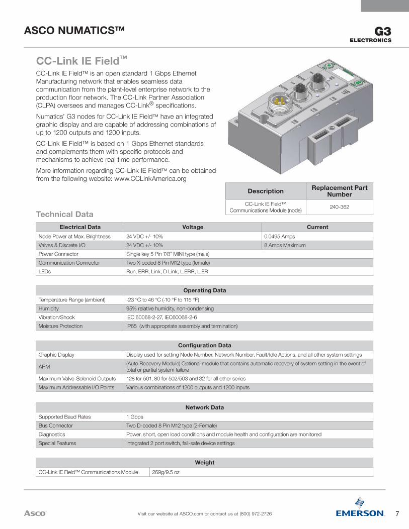
CC-Link IE Field™
CC-Link IE Field™ is an open standard 1 Gbps Ethernet Manufacturing network that enables seamless data communication from the plant-level enterprise network to the production floor network. The CC-Link Partner Association (CLPA) oversees and manages CC-Link® specifications.Numatics’ G3 nodes for CC-Link IE Field™ have an integrated graphic display and are capable of addressing combinations of up to 1200 outputs and 1200 inputs.CC-Link IE Field™ is based on 1 Gbps Ethernet standards and complements them with specific protocols and mechanisms to achieve real time performance.More information regarding CC-Link IE Field™ can be obtained from the following website: www.CCLinkAmerica.org
Description Replacement Part Number
CC-Link IE Field™ Communications Module (node) 240-362

8
ASCO NUMATICS™
Visit our website at ASCO.com or contact us at (800) 972-2726
G3 ELECTRONICS
WeightDeviceNet™ Communications Module 252g/8.9 oz
Network DataSupported Baud Rates 125K Baud, 250K Baud, 500K Baud, with Auto-Baud detectionSupported Connection Type Polled, Cyclic, Change of State (COS) and combination Message CapabilityBus Connector Single key 5 Pin 7/8" MINI type (male)Diagnostics Power, short, open load conditions and module health are monitoredSpecial Features Supports Auto-Device Replacement (ADR) and fail-safe device settings, and QuickConnect™ capability
Configuration Data
Graphic Display Display used for setting Node Address, Baud Rate, Fault/Idle Actions, DeviceNet™ w/ QuickConnect™ and all other system settings
ARM (Auto Recovery Module) Optional module that contains automatic recovery of system setting in the event of total or partial system failure
Maximum Valve-Solenoid Outputs 32Maximum Addressable I/O Points Various combinations of 1200 outputs and 1200 inputs
Operating DataTemperature Range (ambient) -23 °C to 46 °C (-10 °F to 115 °F)Humidity 95% relative humidity, non-condensingVibration/Shock IEC 60068-2-27, IEC60068-2-6Moisture Protection IP65 (with appropriate assembly and termination)
Electrical Data Voltage CurrentNode Power at Max. Brightness 24 VDC +/- 10% 0.0404 AmpsBus Power 11 – 25 VDC 0.025 AmpsValves & Discrete I/O 24 VDC +/- 10% 8 Amps MaximumPower Connector Single key 4 Pin 7/8" MINI type (male)Communication Connector Single key 5 Pin 7/8" MINI type (male)LEDs Module Status and Network Status
Technical Data
DeviceNet™
DeviceNet™ is an open bus fieldbus communication system developed by Allen-Bradley based on Controller Area Network (CAN) technology. The governing body for DeviceNet™ is the Open DeviceNet™ Vendors Association (ODVA). The ODVA controls the DeviceNet™ specification and oversees product conformance testing.Numatics’ G3 nodes for DeviceNet™ have an integrated graphic display and are capable of addressing combinations of up to 1200 outputs and 1200 inputs. They have been tested and approved for conformance by the ODVA.More information about DeviceNet™ and the ODVA can be obtained from the following website: www.odva.org.
Description Replacement Part Number
DeviceNet™ Communications Module (node) 240-180
9
ASCO NUMATICS™
Visit our website at ASCO.com or contact us at (800) 972-2726
G3ELECTRONICS
WeightEtherCAT® Communications Module 227g /8 oz
Network DataSupported Baud Rates 10 Mbit/100 Mbit
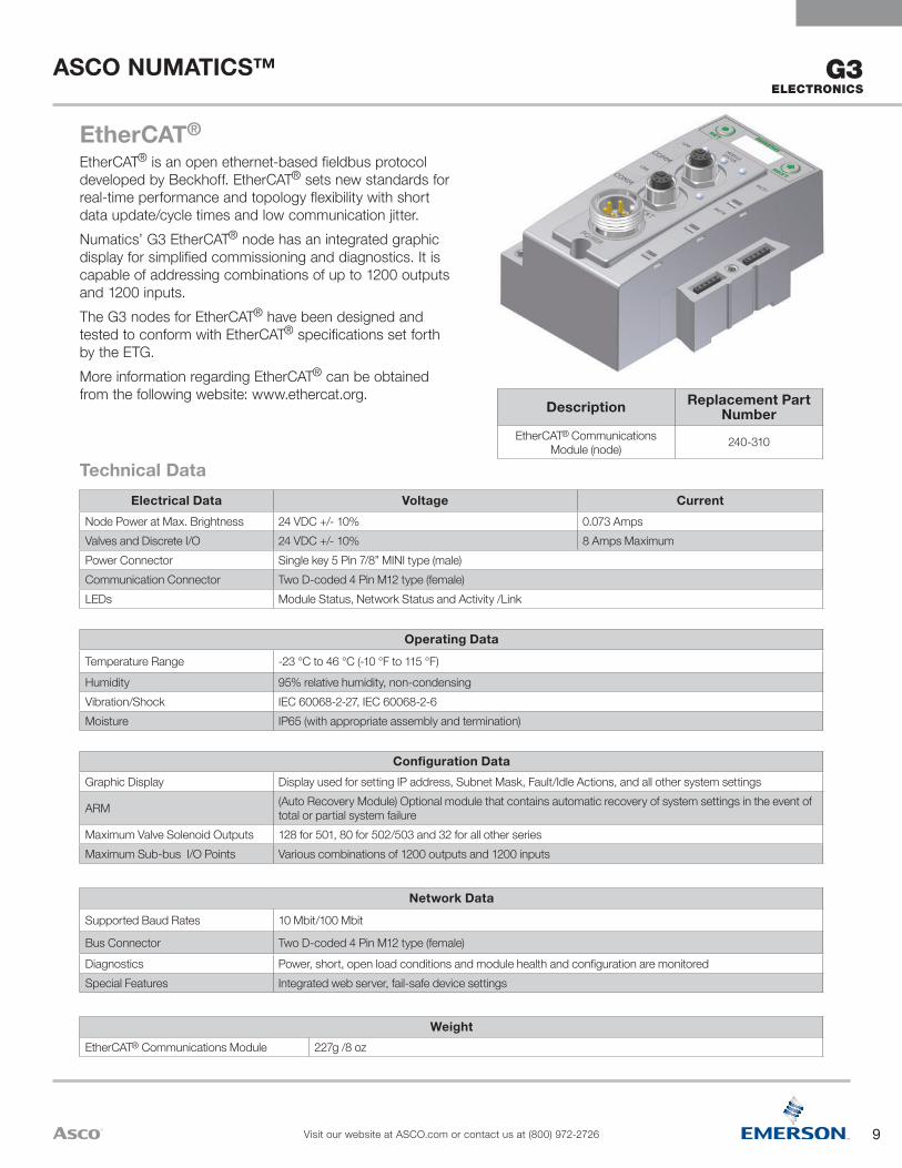
Bus Connector Two D-coded 4 Pin M12 type (female)Diagnostics Power, short, open load conditions and module health and configuration are monitoredSpecial Features Integrated web server, fail-safe device settings
Configuration DataGraphic Display Display used for setting IP address, Subnet Mask, Fault/Idle Actions, and all other system settings
ARM (Auto Recovery Module) Optional module that contains automatic recovery of system settings in the event of total or partial system failure
Maximum Valve Solenoid Outputs 128 for 501, 80 for 502/503 and 32 for all other seriesMaximum Sub-bus I/O Points Various combinations of 1200 outputs and 1200 inputs
Operating DataTemperature Range -23 °C to 46 °C (-10 °F to 115 °F)Humidity 95% relative humidity, non-condensingVibration/Shock IEC 60068-2-27, IEC 60068-2-6Moisture IP65 (with appropriate assembly and termination)
Electrical Data Voltage CurrentNode Power at Max. Brightness 24 VDC +/- 10% 0.073 AmpsValves and Discrete I/O 24 VDC +/- 10% 8 Amps MaximumPower Connector Single key 5 Pin 7/8” MINI type (male)Communication Connector Two D-coded 4 Pin M12 type (female)LEDs Module Status, Network Status and Activity /Link
Technical Data
EtherCAT®
EtherCAT® is an open ethernet-based fieldbus protocol developed by Beckhoff. EtherCAT® sets new standards for real-time performance and topology flexibility with short data update/cycle times and low communication jitter. Numatics’ G3 EtherCAT® node has an integrated graphic display for simplified commissioning and diagnostics. It is capable of addressing combinations of up to 1200 outputs and 1200 inputs.The G3 nodes for EtherCAT® have been designed and tested to conform with EtherCAT® specifications set forth by the ETG.More information regarding EtherCAT® can be obtained from the following website: www.ethercat.org.
Description Replacement Part Number
EtherCAT® Communications Module (node) 240-310
10
ASCO NUMATICS™
Visit our website at ASCO.com or contact us at (800) 972-2726
G3 ELECTRONICS
WeightEtherNet/IP™ Communications Module 255g/9 oz
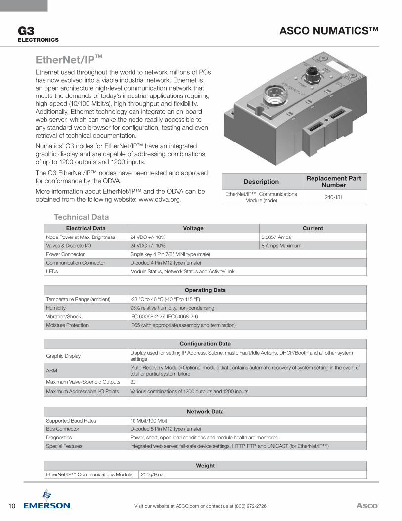
Network DataSupported Baud Rates 10 Mbit/100 MbitBus Connector D-coded 5 Pin M12 type (female)Diagnostics Power, short, open load conditions and module health are monitoredSpecial Features Integrated web server, fail-safe device settings, HTTP, FTP, and UNICAST (for EtherNet/IP™)
Configuration Data
Graphic Display Display used for setting IP Address, Subnet mask, Fault/Idle Actions, DHCP/BootP and all other system settings
ARM (Auto Recovery Module) Optional module that contains automatic recovery of system setting in the event of total or partial system failure
Maximum Valve-Solenoid Outputs 32
Maximum Addressable I/O Points Various combinations of 1200 outputs and 1200 inputs
Operating DataTemperature Range (ambient) -23 °C to 46 °C (-10 °F to 115 °F)Humidity 95% relative humidity, non-condensingVibration/Shock IEC 60068-2-27, IEC60068-2-6Moisture Protection IP65 (with appropriate assembly and termination)
Electrical Data Voltage CurrentNode Power at Max. Brightness 24 VDC +/- 10% 0.0657 AmpsValves & Discrete I/O 24 VDC +/- 10% 8 Amps MaximumPower Connector Single key 4 Pin 7/8" MINI type (male)Communication Connector D-coded 4 Pin M12 type (female) LEDs Module Status, Network Status and Activity/Link
Technical Data
EtherNet/IP™
Ethernet used throughout the world to network millions of PCs has now evolved into a viable industrial network. Ethernet is an open architecture high-level communication network that meets the demands of today’s industrial applications requiring high-speed (10/100 Mbit/s), high-throughput and flexibility. Additionally, Ethernet technology can integrate an on-board web server, which can make the node readily accessible to any standard web browser for configuration, testing and even retrieval of technical documentation.Numatics’ G3 nodes for EtherNet/IP™ have an integrated graphic display and are capable of addressing combinations of up to 1200 outputs and 1200 inputs. The G3 EtherNet/IP™ nodes have been tested and approved for conformance by the ODVA.More information about EtherNet/IP™ and the ODVA can be obtained from the following website: www.odva.org.
Description Replacement Part Number
EtherNet/IP™ Communications Module (node) 240-181

11
ASCO NUMATICS™
Visit our website at ASCO.com or contact us at (800) 972-2726
G3ELECTRONICS
WeightEtherNet/IP™ DLR Communications Module 227g/8 oz
Network DataSupported Baud Rates 10 Mbit/100 MbitBus Connector Two D-coded 4 Pin M12 type (female)Diagnostics Power, short, open load conditions and module health and configuration are monitored
Special Features Embedded two port switch, Device Level Ring (DLR) compatibility, Linear network topology, QuickConnect™ capability, fail-safe device settings, integrated web server, HTTP, TFTP, UNICAST
Configuration DataGraphic Display Display used for setting IP address, Subnet Mask, Fault/Idle Actions, and all other system settings
ARM (Auto Recovery Module) Optional module that contains automatic recovery of system settings in the event of total or partial system failure
Maximum Valve Solenoid Outputs 128 for 501, 80 for 502/503 and 32 for all other seriesMaximum Sub-bus I/O Points Various combinations of 1200 outputs and 1200 inputs
Operating DataTemperature Range -23 °C to 46 °C (-10 °F to 115 °F)Humidity 95% relative humidity, non-condensingVibration/Shock IEC 60068-2-27, IEC 60068-2-6Moisture IP65 (with appropriate assembly and termination)
Electrical Data Voltage CurrentNode Power at Max. Brightness 24 VDC +/- 10% 0.0953 AmpsValves and Discrete I/O 24 VDC +/- 10% 8 Amps MaximumPower Connector Single key 4 Pin 7/8” MINI type (male)Communication Connector Two D-coded 4 Pin M12 type (female)LEDs Module Status, Network Status and Activity/Link
Technical Data
EtherNet/IP™ DLREtherNet/IP™ used throughout the world to network millions of PCs has now evolved into a viable industrial network. EtherNet/IP™ is an open architecture high-level communication network that meets the demands of today’s industrial applications requiring high-speed (10/100 Mbit/s), high-throughput and flexibility. Additionally, EtherNet/IP™ technology can integrate an on-board web server, which can make the node readily accessible to any standard web browser for configuration, testing and even retrieval of technical documentation.Numatics’ G3 EtherNet/IP™ DLR (Device Level Ring) node with integrated display has an embedded switch which allows the unit to be used in simplified networks with linear topology configurations (daisy chain). This technology alleviates the need for an external Ethernet switch device in a single subnet configuration. Additionally, the DLR compatibility allows the node to be used in a fault tolerant “ring” network, when using appropriate EtherNet/IP™ DLR scanners. DLR configuration allows communication recovery from a single point failure on the network ring (e.g. failed network connection or cable).Numatics G3 EtherNet/IP™ nodes are capable of addressing combinations of up to 1200 outputs and 1200 inputs.The G3 EtherNet/IP™ nodes have been tested and approved for conformance by the ODVA.More information about EtherNet/IP™ and the ODVA can be obtained from the following website: www.odva.org.
Description Replacement Part Number
EtherNet/IP™ DLR Communications Module (node) 240-325

12
ASCO NUMATICS™
Visit our website at ASCO.com or contact us at (800) 972-2726
G3 ELECTRONICS
WeightPOWERLINK® Communications Module 227g/8 oz
Network DataSupported Baud Rates 10 Mbit/100 MbitBus Connector Two D-coded 4 Pin M12 type (2-Female)Diagnostics Power, short, open load conditions and module health and configuration are monitoredSpecial Features Integrated web server, Integrated 2 port switch and fail-safe device settings
Configuration DataGraphic Display Display used for setting IP Address, Subnet Mask, Fault/Idle Actions, and all other system settings
ARM (Auto Recovery Module) Optional module that contains automatic recovery of system setting in the event of total or partial system failure
Maximum Valve-Solenoid Outputs 128 for 501, 80 for 502/503 and 32 for all other seriesMaximum Addressable I/O Points Various combinations of 1200 outputs and 1200 inputs
Operating DataTemperature Range (ambient) -23 °C to 46 °C (-10 °F to 115 °F)Humidity 95% relative humidity, non-condensingVibration/Shock IEC 60068-2-27, IEC60068-2-6Moisture Protection IP65 (with appropriate assembly and termination)
Electrical Data Voltage CurrentNode Power at Max. Brightness 24 VDC +/- 10% 0.0955 AmpsValves & Discrete I/O 24 VDC +/- 10% 8 Amps MaximumPower Connector Single key 5 Pin 7/8” MINI type (male)Communication Connector Two D-coded 4 Pin M12 type (female)LEDs Module Status, Network Status and Activity/Link
Technical Data
Ethernet POWERLINK®
Ethernet POWERLINK® is an open fieldbus protocol designed by B&R for communication between automation control systems and distributed I/O at the device level.Numatics' G3 Ethernet POWERLINK® nodes have an integrated graphic display and are capable of addressing combinations of up to 1200 outputs and 1200 inputs.The G3 Ethernet POWERLINK® nodes have been designed and tested to conform to the Ethernet POWERLINK® specifications available at EPSG group (Ethernet Powerlink® Standardization Group). The certification process ensures interoperability for all Ethernet POWERLINK® devices and compatibility with B&R systems.More information regarding Ethernet POWERLINK® can be obtained from the following website: www.ethernet-powerlink.org.
®
Description Replacement Part Number
POWERLINK® communications Module (node) 240-309
Description Replacement Part Number
POWERLINK® Communications Module (node) 240-309

13
ASCO NUMATICS™
Visit our website at ASCO.com or contact us at (800) 972-2726
G3ELECTRONICS
WeightModbus® TCP/IP Communications Module 255g/9 oz
Network DataSupported Baud Rates 10 Mbit/100 MbitBus Connector D-coded 5 Pin M12 type (female)Diagnostics Power, short, open load conditions and module health are monitoredSpecial Features Integrated web server, fail-safe device settings, HTTP, FTP, and UNICAST (for EtherNet/IP™)
Configuration Data
Graphic Display Display used for setting IP Address, Subnet mask, Fault/Idle Actions, DHCP/BootP and all other system settings
ARM (Auto Recovery Module) Optional module that contains automatic recovery of system setting in the event of total or partial system failure
Maximum Valve-Solenoid Outputs 128 for 501, 80 for 502/503 and 32 for all other series
Maximum Addressable I/O Points Various combinations of 1200 outputs and 1200 inputs
Operating DataTemperature Range (ambient) -23 °C to 46 °C (-10 °F to 115 °F)Humidity 95% relative humidity, non-condensingVibration/Shock IEC 60068-2-27, IEC60068-2-6Moisture Protection IP65 (with appropriate assembly and termination)
Electrical Data Voltage CurrentNode Power at Max. Brightness 24 VDC +/- 10% 0.0657 AmpsValves & Discrete I/O 24 VDC +/- 10% 8 Amps MaximumPower Connector Single key 4 Pin 7/8" MINI type (male)Communication Connector D-coded 4 Pin M12 type (female) LEDs Module Status, Network Status and Activity/Link
Technical Data
Modbus® TCP/IPEthernet used throughout the world to network millions of PCs has now evolved into a viable industrial network. Ethernet is an open architecture high-level communication network that meets the demands of today’s industrial applications requiring high-speed (10/100 Mbit/s), high-throughput and flexibility. Additionally, Ethernet technology can integrate an on-board web server, which can make the node readily accessible to any standard web browser for configuration, testing and even retrieval of technical documentation.Numatics’ G3 nodes for Modbus® TCP/IP have an integrated graphic display and are capable of addressing combinations of up to 1200 outputs and 1200 inputs.
Description Replacement Part Number
Modbus® TCP/IP Communications
Module (node)240-292
14
ASCO NUMATICS™
Visit our website at ASCO.com or contact us at (800) 972-2726
G3 ELECTRONICS
WeightPROFIBUS™ DP Communications Module 227g/8 oz
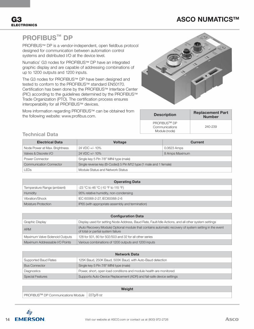
Network DataSupported Baud Rates 125K Baud, 250K Baud, 500K Baud, with Auto-Baud detectionBus Connector Single key 5 Pin 7/8" MINI type (male)Diagnostics Power, short, open load conditions and module health are monitoredSpecial Features Supports Auto-Device Replacement (ADR) and fail-safe device settings
Configuration DataGraphic Display Display used for setting Node Address, Baud Rate, Fault/Idle Actions, and all other system settings
ARM (Auto Recovery Module) Optional module that contains automatic recovery of system setting in the event of total or partial system failure
Maximum Valve-Solenoid Outputs 128 for 501, 80 for 502/503 and 32 for all other seriesMaximum Addressable I/O Points Various combinations of 1200 outputs and 1200 inputs
Operating DataTemperature Range (ambient) -23 °C to 46 °C (-10 °F to 115 °F)Humidity 95% relative humidity, non-condensingVibration/Shock IEC 60068-2-27, IEC60068-2-6Moisture Protection IP65 (with appropriate assembly and termination)
Electrical Data Voltage CurrentNode Power at Max. Brightness 24 VDC +/- 10% 0.0623 AmpsValves & Discrete I/O 24 VDC +/- 10% 8 Amps MaximumPower Connector Single key 5 Pin 7/8” MINI type (male)Communication Connector Single reverse key (B-Coded) 5 Pin M12 type (1 male and 1 female)LEDs Module Status and Network Status
Technical Data
PROFIBUS™ DPPROFIBUS™ DP is a vendor-independent, open fieldbus protocol designed for communication between automation control systems and distributed I/O at the device level.Numatics’ G3 nodes for PROFIBUS™ DP have an integrated graphic display and are capable of addressing combinations of up to 1200 outputs and 1200 inputs. The G3 nodes for PROFIBUS™ DP have been designed and tested to conform to the PROFIBUS™ standard EN50170. Certification has been done by the PROFIBUS™ Interface Center (PIC) according to the guidelines determined by the PROFIBUS™ Trade Organization (PTO). The certification process ensures interoperability for all PROFIBUS™ devices.More information regarding PROFIBUS™ can be obtained from the following website: www.profibus.com. Description Replacement Part
NumberPROFIBUS™ DP Communications
Module (node)240-239
15
ASCO NUMATICS™
Visit our website at ASCO.com or contact us at (800) 972-2726
G3ELECTRONICS
WeightPROFINET™ Communications Module 227g/8 oz
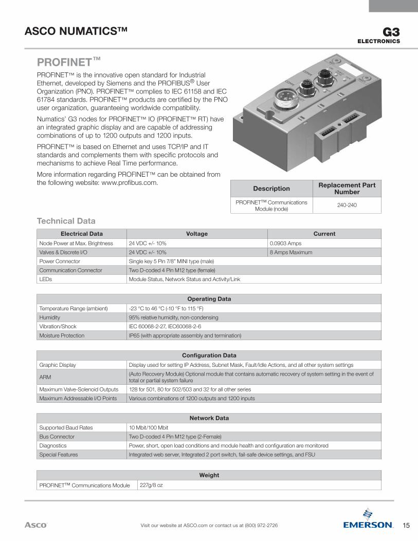
Network DataSupported Baud Rates 10 Mbit/100 MbitBus Connector Two D-coded 4 Pin M12 type (2-Female)Diagnostics Power, short, open load conditions and module health and configuration are monitoredSpecial Features Integrated web server, Integrated 2 port switch, fail-safe device settings, and FSU
Configuration DataGraphic Display Display used for setting IP Address, Subnet Mask, Fault/Idle Actions, and all other system settings
ARM (Auto Recovery Module) Optional module that contains automatic recovery of system setting in the event of total or partial system failure
Maximum Valve-Solenoid Outputs 128 for 501, 80 for 502/503 and 32 for all other seriesMaximum Addressable I/O Points Various combinations of 1200 outputs and 1200 inputs
Operating DataTemperature Range (ambient) -23 °C to 46 °C (-10 °F to 115 °F)Humidity 95% relative humidity, non-condensingVibration/Shock IEC 60068-2-27, IEC60068-2-6Moisture Protection IP65 (with appropriate assembly and termination)
Electrical Data Voltage CurrentNode Power at Max. Brightness 24 VDC +/- 10% 0.0903 AmpsValves & Discrete I/O 24 VDC +/- 10% 8 Amps MaximumPower Connector Single key 5 Pin 7/8” MINI type (male)Communication Connector Two D-coded 4 Pin M12 type (female)LEDs Module Status, Network Status and Activity/Link
Technical Data
PROFINET™
PROFINET™ is the innovative open standard for Industrial Ethernet, developed by Siemens and the PROFIBUS® User Organization (PNO). PROFINET™ complies to IEC 61158 and IEC 61784 standards. PROFINET™ products are certified by the PNO user organization, guaranteeing worldwide compatibility.Numatics’ G3 nodes for PROFINET™ IO (PROFINET™ RT) have an integrated graphic display and are capable of addressing combinations of up to 1200 outputs and 1200 inputs. PROFINET™ is based on Ethernet and uses TCP/IP and IT standards and complements them with specific protocols and mechanisms to achieve Real Time performance. More information regarding PROFINET™ can be obtained from the following website: www.profibus.com.
Description Replacement Part Number
PROFINET™ Communications Module (node) 240-240
16
ASCO NUMATICS™
Visit our website at ASCO.com or contact us at (800) 972-2726
G3 ELECTRONICS
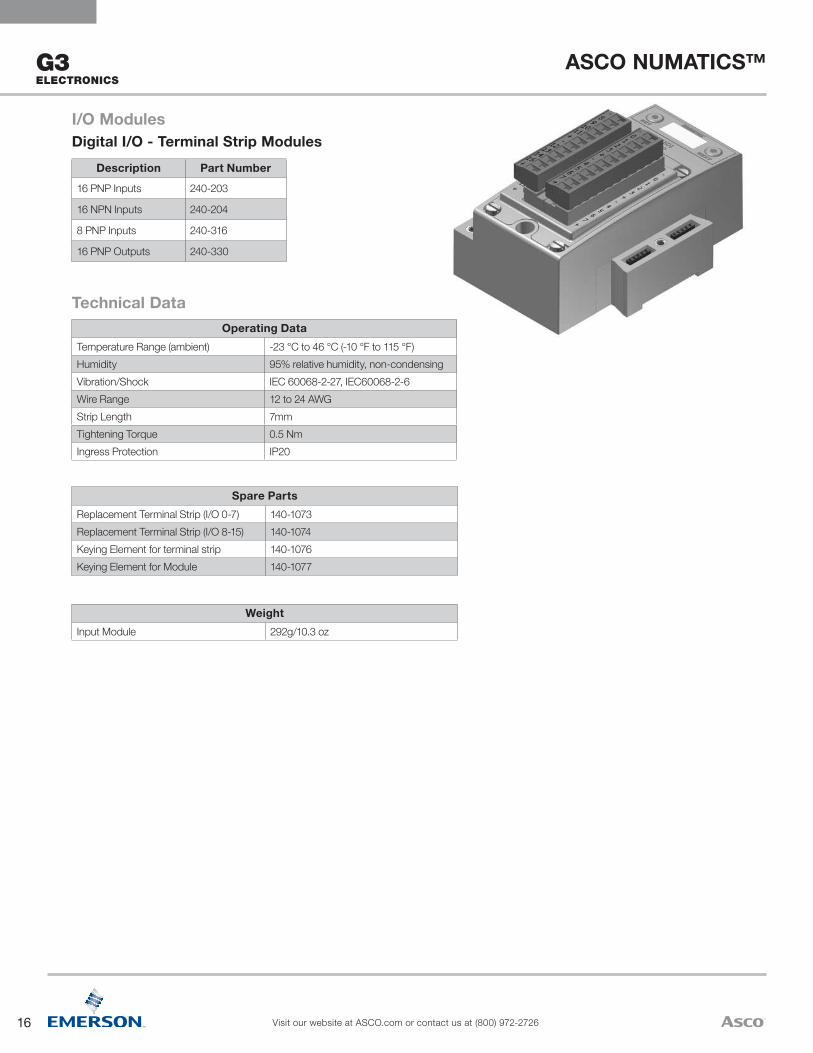
WeightInput Module 292g/10.3 oz
Spare PartsReplacement Terminal Strip (I/O 0-7) 140-1073Replacement Terminal Strip (I/O 8-15) 140-1074Keying Element for terminal strip 140-1076Keying Element for Module 140-1077
Operating DataTemperature Range (ambient) -23 °C to 46 °C (-10 °F to 115 °F)Humidity 95% relative humidity, non-condensingVibration/Shock IEC 60068-2-27, IEC60068-2-6Wire Range 12 to 24 AWGStrip Length 7mmTightening Torque 0.5 NmIngress Protection IP20
Technical Data
Description Part Number
16 PNP Inputs 240-203
16 NPN Inputs 240-204
8 PNP Inputs 240-316
16 PNP Outputs 240-330
I/O ModulesDigital I/O - Terminal Strip Modules
17
ASCO NUMATICS™
Visit our website at ASCO.com or contact us at (800) 972-2726
G3ELECTRONICS
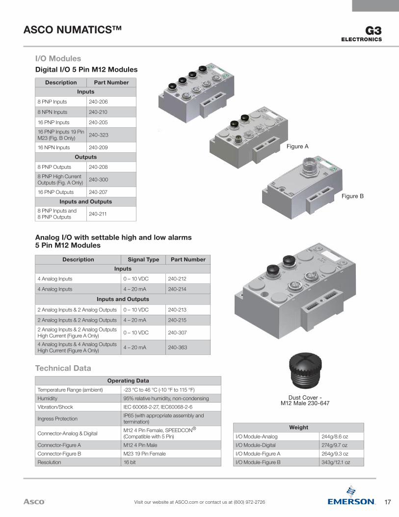
Dust Cover - M12 Male 230-647
Figure B
Figure A
WeightI/O Module-Analog 244g/8.6 ozI/O Module-Digital 274g/9.7 ozI/O Module-Figure A 264g/9.3 ozI/O Module-Figure B 343g/12.1 oz
Operating DataTemperature Range (ambient) -23 °C to 46 °C (-10 °F to 115 °F)Humidity 95% relative humidity, non-condensingVibration/Shock IEC 60068-2-27, IEC60068-2-6
Ingress Protection IP65 (with appropriate assembly and termination)
Connector-Analog & Digital M12 4 Pin Female, SPEEDCON® (Compatible with 5 Pin)
Connector-Figure A M12 4 Pin MaleConnector-Figure B M23 19 Pin FemaleResolution 16 bit
Technical Data
Description Signal Type Part NumberInputs
4 Analog Inputs 0 – 10 VDC 240-212
4 Analog Inputs 4 – 20 mA 240-214
Inputs and Outputs
2 Analog Inputs & 2 Analog Outputs 0 – 10 VDC 240-213
2 Analog Inputs & 2 Analog Outputs 4 – 20 mA 240-215
2 Analog Inputs & 2 Analog Outputs High Current (Figure A Only) 0 – 10 VDC 240-307
4 Analog Inputs & 4 Analog Outputs High Current (Figure A Only) 4 – 20 mA 240-363
Analog I/O with settable high and low alarms 5 Pin M12 Modules
Description Part NumberInputs
8 PNP Inputs 240-206
8 NPN Inputs 240-210
16 PNP Inputs 240-205
16 PNP Inputs 19 Pin M23 (Fig. B Only) 240-323
16 NPN Inputs 240-209
Outputs
8 PNP Outputs 240-208
8 PNP High CurrentOutputs (Fig. A Only) 240-300
16 PNP Outputs 240-207
Inputs and Outputs8 PNP Inputs and 8 PNP Outputs 240-211
I/O ModulesDigital I/O 5 Pin M12 Modules

18
ASCO NUMATICS™
Visit our website at ASCO.com or contact us at (800) 972-2726
G3 ELECTRONICS
Operating DataTemperature Range Ambient -23 ºC to 46 ºC (-10 ºF to 115 ºF )
Humidity 95% relative humidity: non-condensing
Ingress Protection IP65 (with appropriate assembly and terminations)
Mechanical DataI/O Connector M12 4 Pin Female SPEEDCON® (Compatible with 5 Pin)
Mass 284g/10.0 oz
Certification
Module Marking (ATEX) II(1)GD[Ex ia Ga] IIC [Ex ia Da] IIIC
Electrical Data
Voltage 24 VDC Module SupplySensor Supply = 8.2 VDC Nominal
Input Type
NC (Normally Closed)
NAMUR Signal Current (0) ≥ 2.1 mA Signal Current (1) ≤ 1.2 mA Short Circuit Monitoring < 100 Ω Open/Broken Wire Detection < 0.05 mA
Safety Parameter Output MaximumsUo ≤ 9.6 VIo ≤ 13 mAPo ≤ 31 mW
Diagnostics Open (broken wire) and Short Circuit
Technical Data
G3 [Ex ia] NAMUR Input Module 240-320The [Ex ia] module is for use with NAMUR certified intrinsically safe (IS) sensors.
Technical Data
G3 RTD Temperature Module 240-311The RTD module is for use with RTD (Resistive Temperature Detectors), supporting up to four RTD devices simultaneously. The module supports various RTD types including: Pt100, Pt200, Pt500, Pt1000, Ni100 and Ni1000.
Operating DataTemperature Range Ambient -23 ºC to 46 ºC (-10 ºF to 115 ºF )
Humidity 95% relative humidity: non-condensing
Ingress Protection IP65 (with appropriate assembly and terminations)
Mechanical DataI/O Connector M12 4 Pin Female. SPEEDCON® (Compatible with 5 Pin)
Mass 247g/8.7 oz
Electrical DataVoltage 24 VDC Module Supply (Via G3 System Aux. Power Connection)Input Type RTD (Resistive Temperature Detector), 4 per ModuleSupported Sensor Type Pt100, Pt200, Pt500, Pt1000, Ni100, Ni1000Supported Temperature Coefficients .00385; .00392; ….Ω/Ω/°CResolution 15 bits plus signData Format Signed Integer
Calibration Factory Calibrated Field Calibration w/ high tolerance (± .005%) 100 ohm and 350 ohm resistors.
Input Update (filter) Rate Adjustable (5 – 20ms), factory default: 5msAccuracy 0.1% of full scale @ 25 °C
19
ASCO NUMATICS™
Visit our website at ASCO.com or contact us at (800) 972-2726
G3ELECTRONICS
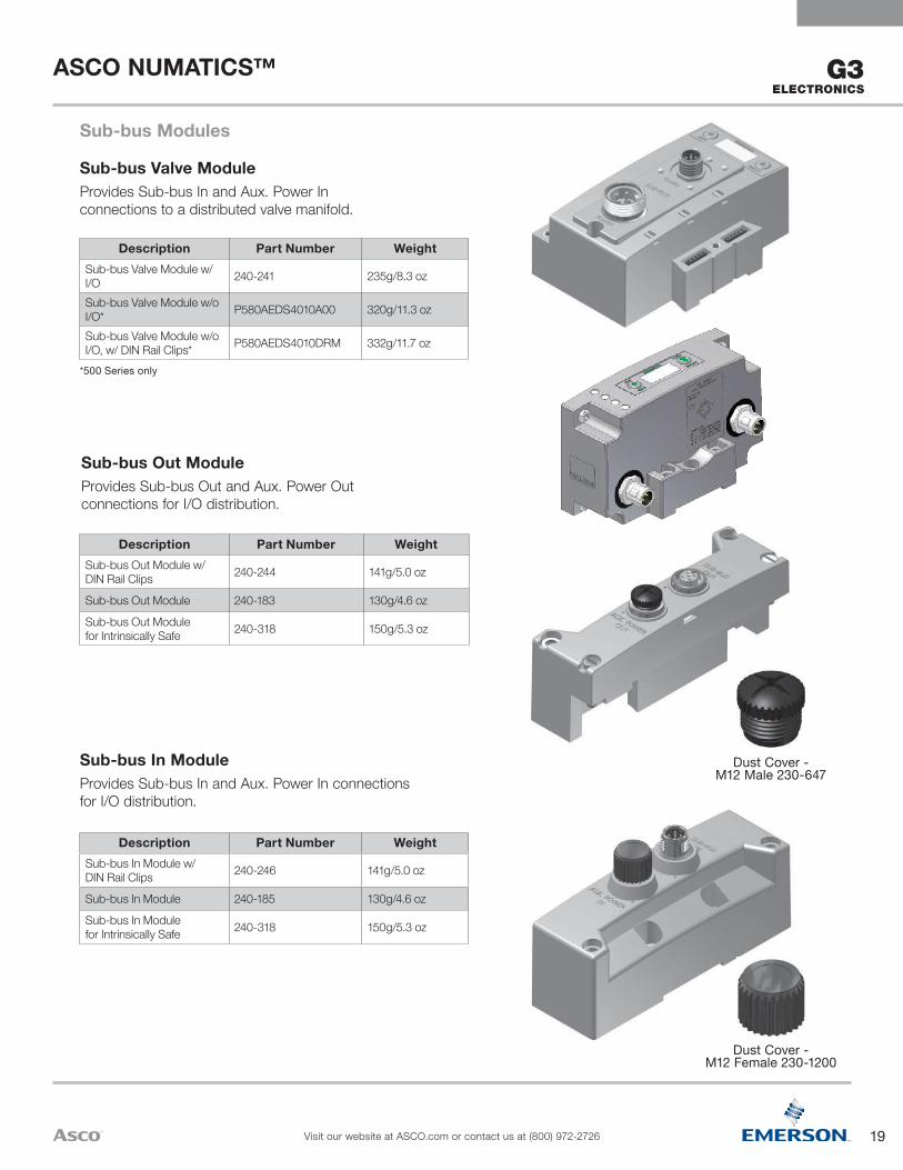
Dust Cover - M12 Male 230-647
Dust Cover - M12 Female 230-1200
Description Part Number WeightSub-bus In Module w/ DIN Rail Clips 240-246 141g/5.0 oz
Sub-bus In Module 240-185 130g/4.6 oz
Sub-bus In Module for Intrinsically Safe 240-318 150g/5.3 oz
Sub-bus In ModuleProvides Sub-bus In and Aux. Power In connections for I/O distribution.
Description Part Number WeightSub-bus Out Module w/ DIN Rail Clips 240-244 141g/5.0 oz
Sub-bus Out Module 240-183 130g/4.6 oz
Sub-bus Out Module for Intrinsically Safe 240-318 150g/5.3 oz
Sub-bus Out ModuleProvides Sub-bus Out and Aux. Power Out connections for I/O distribution.
Description Part Number WeightSub-bus Valve Module w/ I/O 240-241 235g/8.3 oz
Sub-bus Valve Module w/o I/O* P580AEDS4010A00 320g/11.3 oz
Sub-bus Valve Module w/o I/O, w/ DIN Rail Clips* P580AEDS4010DRM 332g/11.7 oz
*500 Series only
Sub-bus Valve ModuleProvides Sub-bus In and Aux. Power In connections to a distributed valve manifold.
Sub-bus Modules
20
ASCO NUMATICS™
Visit our website at ASCO.com or contact us at (800) 972-2726
G3 ELECTRONICS
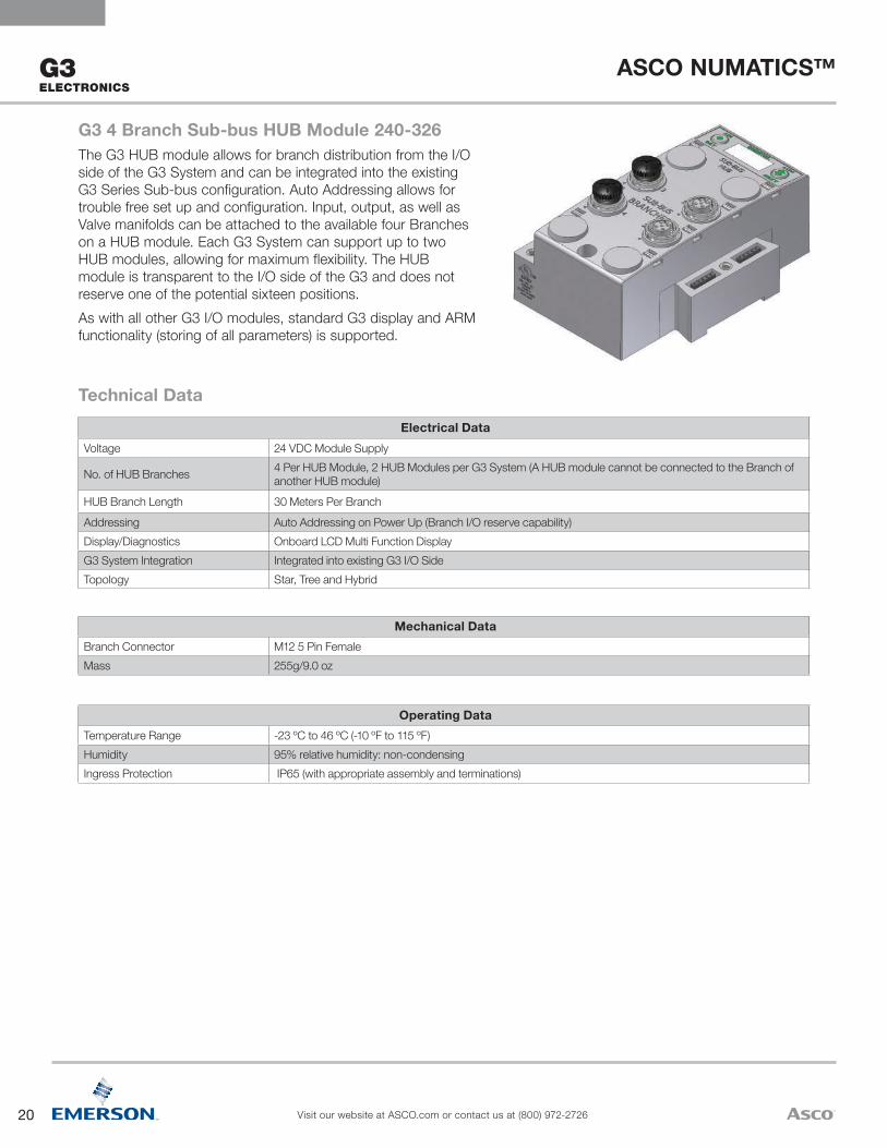
Operating DataTemperature Range -23 ºC to 46 ºC (-10 ºF to 115 ºF)Humidity 95% relative humidity: non-condensingIngress Protection IP65 (with appropriate assembly and terminations)
Mechanical DataBranch Connector M12 5 Pin Female Mass 255g/9.0 oz
Electrical DataVoltage 24 VDC Module Supply
No. of HUB Branches 4 Per HUB Module, 2 HUB Modules per G3 System (A HUB module cannot be connected to the Branch of another HUB module)
HUB Branch Length 30 Meters Per BranchAddressing Auto Addressing on Power Up (Branch I/O reserve capability)Display/Diagnostics Onboard LCD Multi Function DisplayG3 System Integration Integrated into existing G3 I/O SideTopology Star, Tree and Hybrid
Technical Data
G3 4 Branch Sub-bus HUB Module 240-326The G3 HUB module allows for branch distribution from the I/O side of the G3 System and can be integrated into the existing G3 Series Sub-bus configuration. Auto Addressing allows for trouble free set up and configuration. Input, output, as well as Valve manifolds can be attached to the available four Branches on a HUB module. Each G3 System can support up to two HUB modules, allowing for maximum flexibility. The HUB module is transparent to the I/O side of the G3 and does not reserve one of the potential sixteen positions.As with all other G3 I/O modules, standard G3 display and ARM functionality (storing of all parameters) is supported.
21
ASCO NUMATICS™
Visit our website at ASCO.com or contact us at (800) 972-2726
G3ELECTRONICS
Description Part Number Weight
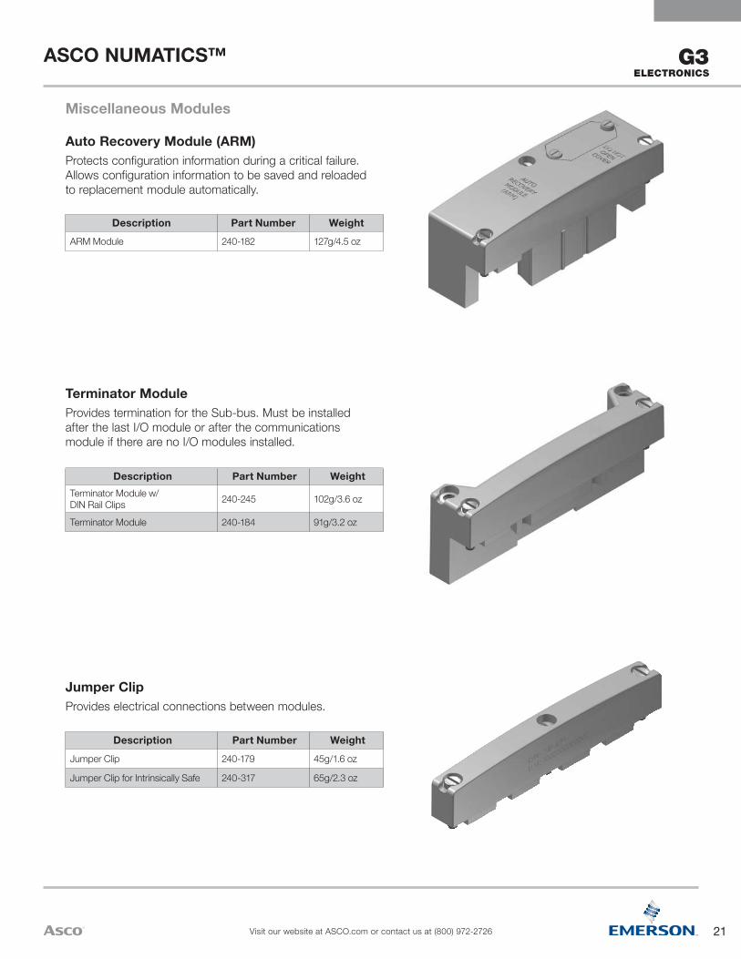
Jumper Clip 240-179 45g/1.6 oz
Jumper Clip for Intrinsically Safe 240-317 65g/2.3 oz
Jumper ClipProvides electrical connections between modules.
Description Part Number WeightTerminator Module w/ DIN Rail Clips 240-245 102g/3.6 oz
Terminator Module 240-184 91g/3.2 oz
Terminator ModuleProvides termination for the Sub-bus. Must be installed after the last I/O module or after the communications module if there are no I/O modules installed.
Description Part Number WeightARM Module 240-182 127g/4.5 oz
Auto Recovery Module (ARM)Protects configuration information during a critical failure. Allows configuration information to be saved and reloaded to replacement module automatically.
Miscellaneous Modules
22
ASCO NUMATICS™
Visit our website at ASCO.com or contact us at (800) 972-2726
G3 ELECTRONICS
{Technical Data
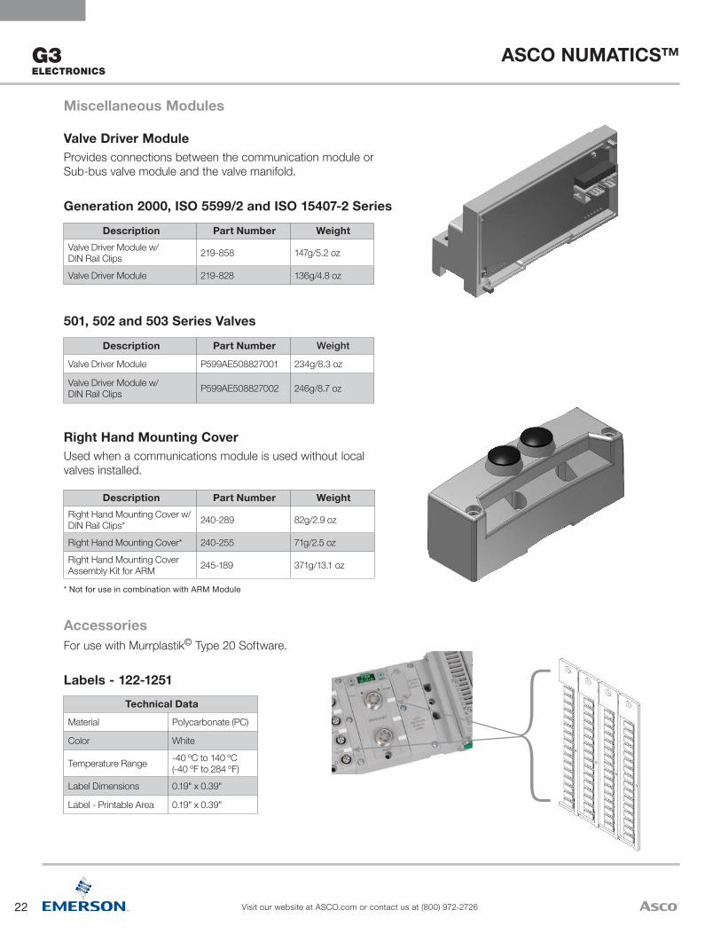
Material Polycarbonate (PC)
Color White
Temperature Range -40 ºC to 140 ºC (-40 ºF to 284 ºF)
Label Dimensions 0.19" x 0.39"
Label - Printable Area 0.19" x 0.39"
Labels - 122-1251
AccessoriesFor use with Murrplastik© Type 20 Software.
Description Part Number WeightRight Hand Mounting Cover w/ DIN Rail Clips* 240-289 82g/2.9 oz
Right Hand Mounting Cover* 240-255 71g/2.5 oz
Right Hand Mounting Cover Assembly Kit for ARM 245-189 371g/13.1 oz
* Not for use in combination with ARM Module
Right Hand Mounting CoverUsed when a communications module is used without local valves installed.
Description Part Number Weight
Valve Driver Module P599AE508827001 234g/8.3 oz
Valve Driver Module w/ DIN Rail Clips P599AE508827002 246g/8.7 oz
501, 502 and 503 Series Valves
Description Part Number WeightValve Driver Module w/ DIN Rail Clips 219-858 147g/5.2 oz
Valve Driver Module 219-828 136g/4.8 oz
Generation 2000, ISO 5599/2 and ISO 15407-2 Series
Valve Driver ModuleProvides connections between the communication module or Sub-bus valve module and the valve manifold.
Miscellaneous Modules
23
ASCO NUMATICS™
Visit our website at ASCO.com or contact us at (800) 972-2726
G3ELECTRONICS
G
W
S TR
U
V
X
Y Z AA
H
AD
BA M
L
NP Q
AB
AC
CD
E
F J K
6.3 Wide Slot(2) Places
Ø5.4
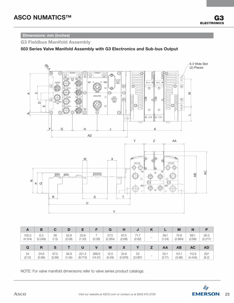
503 Series Valve Manifold Assembly with G3 Electronics and Sub-bus OutputG3 Fieldbus Manifold AssemblyDimensions: mm (inches)
A B C D E F G H J K L M N P105.5(4.154)
6.3(0.248)
38(1.5)
52.8(2.08)
33.8(1.33)
7(0.28)
57.5(2.264)
67.5(2.66)
71.7(2.82) – 39.1
(1.54)75.8
(2.984)68.1(2.68)
56.3(2.217)
Q R S T U V W X Y Z AA AB AC AD54
(2.13)24.8(0.98)
67.5(2.66)
36.9(1.45)
221.3(8.713)
368.6(14.51)
12.5(0.49)
24.8(0.976)
53(2.087) – 55.1
(2.17)101.1(3.98)
112.9(4.445)
207(8.2)
NOTE: For valve manifold dimensions refer to valve series product catalogs.

24
ASCO NUMATICS™
Visit our website at ASCO.com or contact us at (800) 972-2726
G3 ELECTRONICS
A B C
E
P
N R
K L M
J
T U
VIEW SHOWN WITH OPTIONAL DINRAIL HARDWARE AND 35mm DIN
RAIL
S
ADDITIONAL MOUNTING HOLES (4) FOR USE WITH M5 OR #10 SCREWS
F
FOR USE WITH OPTIONALDIN RAIL HARDWARE
G
H D
A B C D E F G H J K L M N P R S T U46.35 (1.82)
67.50 (2.66)
57.50 (2.26)
6.90 (0.27)
105.50 (4.15)
38.00 (1.50)
33.75 (1.33)
6.25 (0.25)
185.25 (7.29)
13.50 (0.53)
67.25 (2.65)
36.75 (1.45)
54.00 (2.13)
12.50 (0.49)
62.50 (2.46)
5.05 (0.20)
59.00 (2.32)
118.00 (4.65)
I/O Assembly with G3 Electronics and Sub-bus InputG3 Fieldbus I/O AssemblyDimensions: mm (inches)

25
ASCO NUMATICS™
Visit our website at ASCO.com or contact us at (800) 972-2726
G3ELECTRONICS
1 Port Type 8 & G only available in Port Size 3/8 for 502 & 503 and 1/8 for 5012 501 not available with 2 stations, 502 and 503 only available with an even number of stations and with up to 80 valve solenoids3 With 502 11mm (501) valve available, with 503 18mm (502) valve available4 501 Port Sizes 1/8, 1/4, 5/16, 8mm, 502 and 530 Port Sizes 3/8, 1/2, 10 and 12mm
Port Size1 = 1/82 = 1/4G = 5/163 = 3/84 = 1/2H = 8mmK = 10mmM = 12mm
Valve Station Adder0 = No Adder1 = 32+2 = 64+3 = 96+
Second Valve Series0 = No Second Valve Series1 = 5012 = 502
End Plate StyleV = Vertical
OptionsA00 = Standard (No Options)MUF = Muffler in End PlatesDRM = DIN Rail MountDWM = DIN Rail with MUF14X = External Pilot Supply from Port # 14D12 = (14X) External Pilot Supply from Port #14
and (MUF) Muffler in End PlatesD14 = (14X) External Pilot Supply from Port #14
and (DRM) DIN Rail MountF06 = (14X) External Pilot Supply from Port
#14, (MUF) Muffler in End Plates, and (DRM) DIN Rail Mount
Number of Valve StationsA = NA/33/65/97B = 2/34/66/98C = 3/35/67/99D = 4/36/68/100E = NA/37/69/101F = 6/38/70/102G = 7/39/71/103H = 8/40/72/104I = 9/41/73/105J = 10/42/74/106K = 11/43/75/107L = 12/44/76/108M = 13/45/77/109N = 14/46/78/110O = 15/47/79/111P = 16/48/80/112
Q = 17/49/81/113R = 18/50/82/114S = 19/51/83/115T = 20/52/84/116U = 21/53/85/117V = 22/54/86/118W = 23/55/87/119X = 24/56/88/120Y = 25/57/89/121Z = 26/58/90/1222 = 27/59/91/1233 = 28/60/92/1244 = 29/61/93/1255 = 30/62/94/1266 = 31/63/95/1277 = 32/64/96/128
Electronics3 = G3 Fieldbus Electronics 8 = Sub-bus Valve Manifold w/o I/O
Product TypeV = Valve Manifold Assembly
RevisionA = Initial Release
Product Series501 = 11mm Valve502 = 18mm Valve503 = 26mm Valve
Port Type8 = NPTFG = ISO228/1-GK = Push-in Fittings
K 501 A V 3 D 2 0 0 V A00
How To Order: 500 Series Manifold Assembly
1
1
2
4
3
26
ASCO NUMATICS™
Visit our website at ASCO.com or contact us at (800) 972-2726
G3 ELECTRONICS
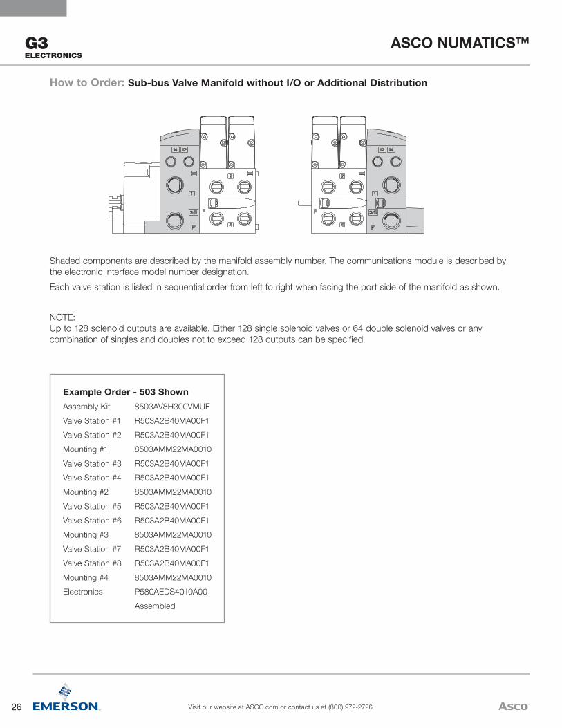
Shaded components are described by the manifold assembly number. The communications module is described by the electronic interface model number designation.Each valve station is listed in sequential order from left to right when facing the port side of the manifold as shown.
NOTE: Up to 128 solenoid outputs are available. Either 128 single solenoid valves or 64 double solenoid valves or any combination of singles and doubles not to exceed 128 outputs can be specified.
How to Order: Sub-bus Valve Manifold without I/O or Additional Distribution
Example Order - 503 ShownAssembly Kit 8503AV8H300VMUFValve Station #1 R503A2B40MA00F1Valve Station #2 R503A2B40MA00F1Mounting #1 8503AMM22MA0010Valve Station #3 R503A2B40MA00F1Valve Station #4 R503A2B40MA00F1Mounting #2 8503AMM22MA0010Valve Station #5 R503A2B40MA00F1Valve Station #6 R503A2B40MA00F1Mounting #3 8503AMM22MA0010Valve Station #7 R503A2B40MA00F1Valve Station #8 R503A2B40MA00F1Mounting #4 8503AMM22MA0010Electronics P580AEDS4010A00 Assembled
27
ASCO NUMATICS™
Visit our website at ASCO.com or contact us at (800) 972-2726
G3ELECTRONICS
How To OrderG3 Electronics
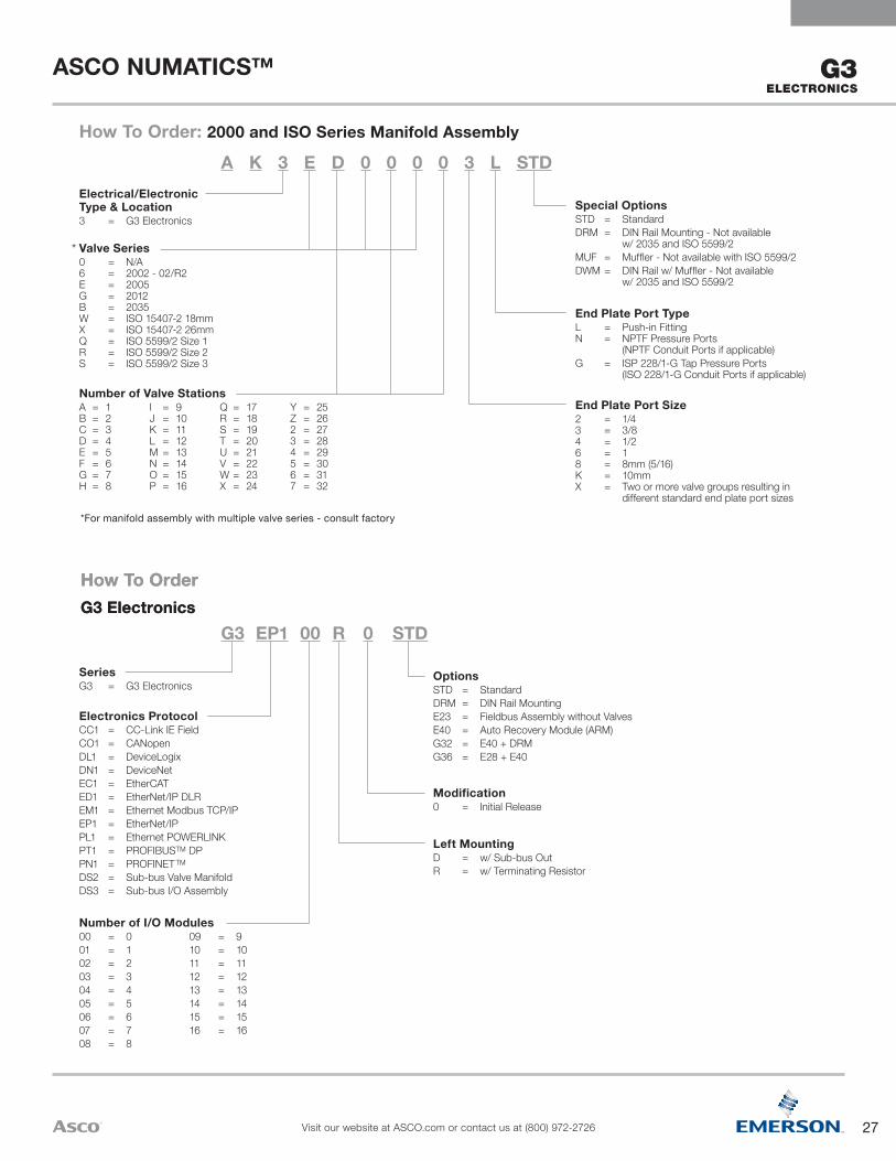
How To Order: 2000 and ISO Series Manifold Assembly
Left MountingD = w/ Sub-bus OutR = w/ Terminating Resistor
Modification0 = Initial Release
OptionsSTD = StandardDRM = DIN Rail MountingE23 = Fieldbus Assembly without ValvesE40 = Auto Recovery Module (ARM)G32 = E40 + DRMG36 = E28 + E40
Number of I/O Modules00 = 001 = 102 = 203 = 304 = 405 = 506 = 607 = 708 = 8
09 = 910 = 1011 = 1112 = 1213 = 1314 = 1415 = 1516 = 16
Electronics ProtocolCC1 = CC-Link IE FieldCO1 = CANopenDL1 = DeviceLogixDN1 = DeviceNetEC1 = EtherCATED1 = EtherNet/IP DLREM1 = Ethernet Modbus TCP/IPEP1 = EtherNet/IPPL1 = Ethernet POWERLINKPT1 = PROFIBUSTM DPPN1 = PROFINETTM
DS2 = Sub-bus Valve ManifoldDS3 = Sub-bus I/O Assembly
SeriesG3 = G3 Electronics
G3 EP1 00 R 0 STD
*For manifold assembly with multiple valve series - consult factory
End Plate Port Size2 = 1/4 3 = 3/8 4 = 1/2 6 = 1 8 = 8mm (5/16) K = 10mm X = Two or more valve groups resulting in different standard end plate port sizes
End Plate Port TypeL = Push-in Fitting N = NPTF Pressure Ports (NPTF Conduit Ports if applicable)G = ISP 228/1-G Tap Pressure Ports (ISO 228/1-G Conduit Ports if applicable)
Special OptionsSTD = StandardDRM = DIN Rail Mounting - Not available w/ 2035 and ISO 5599/2MUF = Muffler - Not available with ISO 5599/2DWM = DIN Rail w/ Muffler - Not available w/ 2035 and ISO 5599/2
Number of Valve StationsA = 1 B = 2 C = 3 D = 4 E = 5 F = 6 G = 7 H = 8
I = 9 J = 10 K = 11 L = 12 M = 13 N = 14 O = 15 P = 16
Q = 17 R = 18 S = 19 T = 20 U = 21 V = 22 W = 23 X = 24
Y = 25 Z = 26 2 = 27 3 = 28 4 = 29 5 = 30 6 = 31 7 = 32
Valve Series0 = N/A 6 = 2002 - 02/R2 E = 2005 G = 2012 B = 2035 W = ISO 15407-2 18mm X = ISO 15407-2 26mm Q = ISO 5599/2 Size 1 R = ISO 5599/2 Size 2 S = ISO 5599/2 Size 3
Electrical/Electronic Type & Location3 = G3 Electronics
A K 3 E D 0 0 0 0 3 L STD
How To OrderG3 Electronics
*

28
ASCO NUMATICS™
Visit our website at ASCO.com or contact us at (800) 972-2726
G3 ELECTRONICS
116
16 1 1 152 3 16
Example Order - I/O Assembly w/ Sub-bus In and Sub-bus Out Modules ShownElectronics G3DS316D0STD Station 1 240-205 Station 2 240-205 Station 15 240-205 Station 16 240-205
1. Refer to the selection table on the previous page to specify the control electronics and I/O configuration.
2. Each discrete I/O module is listed in sequential order from RIGHT to LEFT as shown.
3. A maximum of 16 I/O modules are supported by a single communication node. Analog I/O & digital I/O (NPN & PNP)
How To OrderG3 Electronics
Example Order - 2005 ShownAssembly Kit AK3EP00003LMUF Station 1 052BB4Z2ML00061 Station 2 052BB4Z2ML00061 Station 3 052BB4Z2ML00061 Station 4 052BB4Z2ML00061 Station 5 052BB4Z2ML00061 Station 6 052BB4Z2ML00061 Station 7 052BB4Z2ML00061 Station 8 052BB4Z2ML00061 Station 9 052BB4R2ML00061 Station 10 052BB4Z2ML00061 Station 11 052BB4Z2ML00061 Station 12 052BB4Z2ML00061 Station 13 052BB4Z2ML00061 Station 14 052BB4Z2ML00061 Station 15 052BB4Z2ML00061 Station 16 052BB4Z2ML00061 Electronics G3DN116R0E40 Station 1 240-205 Station 2 240-205
Station 15 240-205 Station 16 240-205
Shaded components are described by the assembly kit (AK) model number (see previous page). The communications module and number of I/O modules are described by the electronic interface (G3) model number designation (see previous page).Each valve station is listed in sequential order from left to right when facing the port side of the manifold as shown.Each discrete I/O module is listed in sequential order from RIGHT to LEFT starting from the communication module as shown.NOTE:1. A total of 32 solenoid outputs are available. Either 32 single solenoid
valves or 16 double solenoid valves or any combination of singles and doubles not to exceed 32 outputs can be specified.
2. For manifold assemblies that exceed 16 solenoids, the assembly MUST be configured so that an even number of solenoids are utilized prior to the station using the ribbon cable feature. The 16th and the 17th solenoids cannot be on the same valve.
How to Order: Valve Manifold Assemblies w/ G3 Electronics & Discrete I/OFor valve series 2002, 2005, 2012, 2035, ISO 15407-2 & ISO 5599/2 (2005 shown)
29
ASCO NUMATICS™
Visit our website at ASCO.com or contact us at (800) 972-2726
SERIES
501
501 PERFORMANCE
& HOW TO ORDER
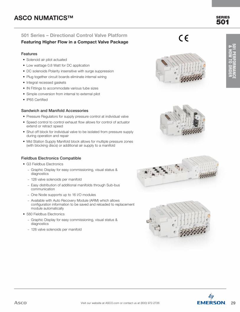
Fieldbus Electronics Compatible• G3 Fieldbus Electronics
– Graphic Display for easy commissioning, visual status & diagnostics
– 128 valve solenoids per manifold – Easy distribution of additional manifolds through Sub-bus communication
– One Node supports up to 16 I/O modules – Available with Auto Recovery Module (ARM) which allows configuration information to be saved and reloaded to replacement module automatically
• 580 Fieldbus Electronics – Graphic Display for easy commissioning, visual status & diagnostics
– 128 valve solenoids per manifold
Sandwich and Manifold Accessories• Pressure Regulators for supply pressure control at individual valve• Speed control to control exhaust flow allows for control of actuator
extend or retract speed• Shut off block for individual valve to be isolated from pressure supply
during operation and repair• Mid Station Supply Manifold block allows for multiple pressure zones
(with blocking discs) or additional air supply to a manifold
Features• Solenoid air pilot actuated• Low wattage 0.8 Watt for DC application• DC solenoids Polarity insensitive with surge suppression• Plug together circuit boards eliminate internal wiring• Integral recessed gaskets• IN Fittings to accommodate various tube sizes • Simple conversion from internal to external pilot• IP65 Certified
501 Series – Directional Control Valve PlatformFeaturing Higher Flow in a Compact Valve Package
30
ASCO NUMATICS™
Visit our website at ASCO.com or contact us at (800) 972-2726
SERIES
501
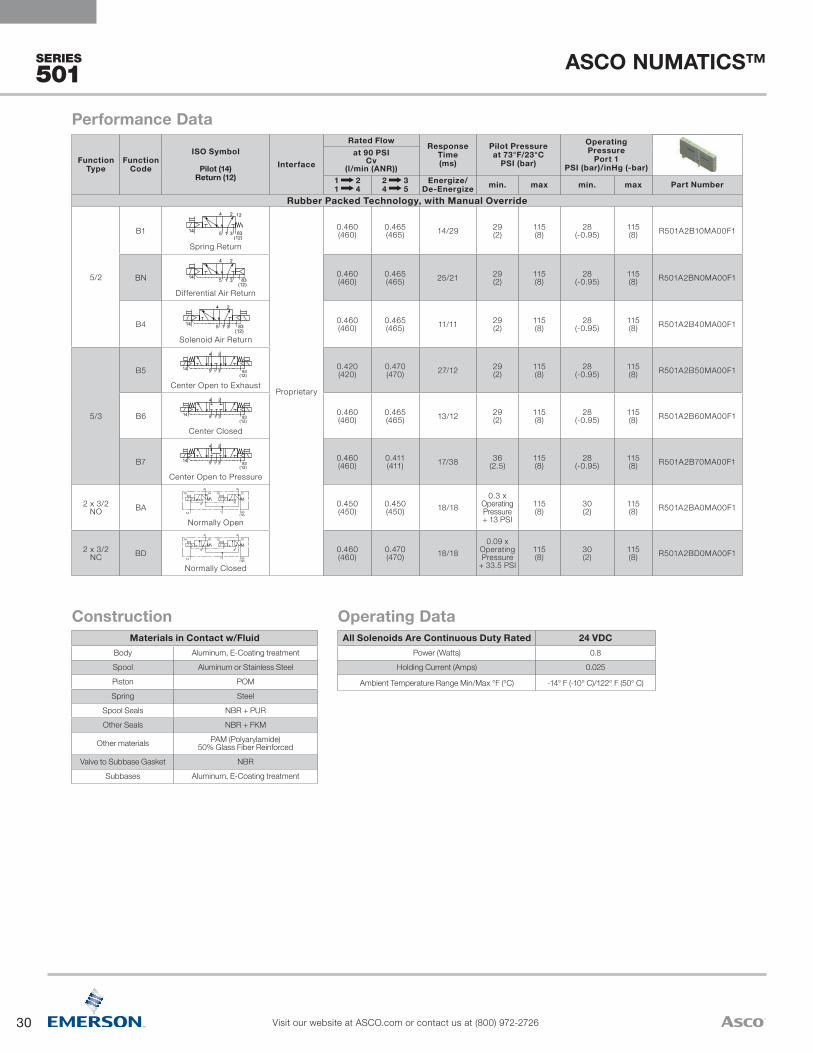
All Solenoids Are Continuous Duty Rated 24 VDCPower (Watts) 0.8
Holding Current (Amps) 0.025
Ambient Temperature Range Min/Max °F (°C) -14° F (-10° C)/122° F (50° C)
Operating DataMaterials in Contact w/Fluid
Body Aluminum, E-Coating treatment
Spool Aluminum or Stainless Steel
Piston POM
Spring Steel
Spool Seals NBR + PUR
Other Seals NBR + FKM
Other materials PAM (Polyarylamide) 50% Glass Fiber Reinforced
Valve to Subbase Gasket NBR
Subbases Aluminum, E-Coating treatment
Construction
Function Type
Function Code
ISO Symbol
Pilot (14) Return (12)
Interface
Rated Flow Response Time (ms)
Pilot Pressure at 73°F/23°C
PSI (bar)
Operating Pressure
Port 1 PSI (bar)/inHg (-bar)
at 90 PSI Cv
(l/min (ANR))1 2 1 4
2 3 4 5
Energize/De-Energize min. max min. max Part Number
Rubber Packed Technology, with Manual Override
5/2
B1
1
4 2
35 1
4 2
3514
14 1
4 2
35
12
1
4 2
35
14 1
4 2
351
4 2
35
14
14
14
1
4 2
35 1
4 2
3514
14 1
4 2
35
12
1
4 2
35
14 1
4 2
351
4 2
35
14
14
14
SYMBOLES PNEUMATIQUES DISTRIBUTEUR 5/2
5/2 PNEUMATIC SYMBOLS
83(12)
004A1
004A3
004A5
004A6
004A8
004A10
004F1
004F3
004F5
004F6
004F8
004F10
14 1
4 2
351
4 2
35 83(12)
14 12
14 1
4 2
351
4 2
35
1214
004A14 004F14
004A15 004F15
SYMBOLES PNEUMATIQUES DISTRIBUTEUR 5/2 - VERSION METAL METAL
5/2 PNEUMATIC SYMBOLS - SPOOL AND SLEEVE VERSION
1
4 2
3514 1
4 2
35
14
1
4 2
3514 1
4 2
35
14
1
4 2
3514 1
4 2
35
14
1
4 2
3514 1
4 2
35
1
4 2
3514 1
4 2
35
1
4 2
3514 1
4 2
35
14
14
14
005A1 005F1
005A2 005F2
005A3 005F3
005A4 005F4
005A5 005F5
005A6 005F6
5
4
5
3
3
2
5
3
3
5
14 12
14 10
10 10
10 12
5
5
3
3
5
3
3
5
14 12
14 10
10 10
10 12
10 10 10 10
10 12 10 12
14 12 14 12
14 10 14 10
5
5
3
3
5
3
3
5
14 12
14 10
10 10
10 12
5
5
3
3
5
3
3
5
14 12
14 10
10 10
10 12
10 10 10 10
10 12 10 12
14 12 14 12
14 10 14 10
1
006A9 006F9
006A10 006F10
006A11 006F11
006A12 006F12
006A13 006F13
006A14 006F14
006A15 006F15
006A16 006F16
1
1
1
1
1
1
1
1
1
1
1
1
1
1
1
83(12)
4 2
4 2
4 2
4 2
4 2
4 2
4 2
4 2
4 2
4 2
4 2
4 2
4 2
4 2
4 2
SYMBOLES PNEUMATIQUES DISTRIBUTEUR 5/3
5/3 PNEUMATIC SYMBOLS
SYMBOLES PNEUMATIQUES DISTRIBUTEUR 2X 3/2
2X 3/2 PNEUMATIC SYMBOLS
83(12)
14
14
14
14
14
14
14
14
83(12)
83(12)
83(12)
83(12)
83(12)
83(12)
83(12)
83(12)
83(12)
83(12)
83(12)
83(12)
83(12)
83(12)
83(12)
83(12)
83(12)
83(12)
83(12)
83(12)
83(12)
83(12)
83(12)
83(12)
83(12)
83(12)
83(12)
83(12)
83(12)
83(12)
83(12)
83(12)
83(12)
83(12)
83(12)
83(12)
83(12)
83(12)
83(12)
83(12)
005A7 005F7
005A8 005F8
SYMBOLES PNEUMATIQUES DISTRIBUTEUR 5/3 W2 - VERSION METAL METAL
5/3 W2 PNEUMATIC SYMBOLS - SPOOL AND SLEEVE VERSION
NOTA / NOTE:SYMBOLES SELON LES NORMES ISO NF ISO 1219-1 Janvier 2007SYMBOLS AS PER ISO NF ISO 1219-1 January 2007
(A)
1483
(12)1
4 2
35
1483
(12)1
4 2
35
14
83(12)
1
4 2
35
14
83(12)
1
4 2
35
√
Spring Return
Proprietary
0.460 (460)
0.465 (465) 14/29 29
(2)115 (8)
28 (-0.95)
115 (8) R501A2B10MA00F1
BN 1
4 2
35 1
4 2
3514
14 1
4 2
35
12
1
4 2
35
14 1
4 2
351
4 2
35
14
14
14
1
4 2
35 1
4 2
3514
14 1
4 2
35
12
1
4 2
35
14 1
4 2
351
4 2
35
14
14
14
SYMBOLES PNEUMATIQUES DISTRIBUTEUR 5/2
5/2 PNEUMATIC SYMBOLS
83(12)
004A1
004A3
004A5
004A6
004A8
004A10
004F1
004F3
004F5
004F6
004F8
004F10
14 1
4 2
351
4 2
35 83(12)
14 12
14 1
4 2
351
4 2
35
1214
004A14 004F14
004A15 004F15
SYMBOLES PNEUMATIQUES DISTRIBUTEUR 5/2 - VERSION METAL METAL
5/2 PNEUMATIC SYMBOLS - SPOOL AND SLEEVE VERSION
1
4 2
3514 1
4 2
35
14
1
4 2
3514 1
4 2
35
14
1
4 2
3514 1
4 2
35
14
1
4 2
3514 1
4 2
35
1
4 2
3514 1
4 2
35
1
4 2
3514 1
4 2
35
14
14
14
005A1 005F1
005A2 005F2
005A3 005F3
005A4 005F4
005A5 005F5
005A6 005F6
5
4
5
3
3
2
5
3
3
5
14 12
14 10
10 10
10 12
5
5
3
3
5
3
3
5
14 12
14 10
10 10
10 12
10 10 10 10
10 12 10 12
14 12 14 12
14 10 14 10
5
5
3
3
5
3
3
5
14 12
14 10
10 10
10 12
5
5
3
3
5
3
3
5
14 12
14 10
10 10
10 12
10 10 10 10
10 12 10 12
14 12 14 12
14 10 14 10
1
006A9 006F9
006A10 006F10
006A11 006F11
006A12 006F12
006A13 006F13
006A14 006F14
006A15 006F15
006A16 006F16
1
1
1
1
1
1
1
1
1
1
1
1
1
1
1
83(12)
4 2
4 2
4 2
4 2
4 2
4 2
4 2
4 2
4 2
4 2
4 2
4 2
4 2
4 2
4 2
SYMBOLES PNEUMATIQUES DISTRIBUTEUR 5/3
5/3 PNEUMATIC SYMBOLS
SYMBOLES PNEUMATIQUES DISTRIBUTEUR 2X 3/2
2X 3/2 PNEUMATIC SYMBOLS
83(12)
14
14
14
14
14
14
14
14
83(12)
83(12)
83(12)
83(12)
83(12)
83(12)
83(12)
83(12)
83(12)
83(12)
83(12)
83(12)
83(12)
83(12)
83(12)
83(12)
83(12)
83(12)
83(12)
83(12)
83(12)
83(12)
83(12)
83(12)
83(12)
83(12)
83(12)
83(12)
83(12)
83(12)
83(12)
83(12)
83(12)
83(12)
83(12)
83(12)
83(12)
83(12)
83(12)
83(12)
005A7 005F7
005A8 005F8
SYMBOLES PNEUMATIQUES DISTRIBUTEUR 5/3 W2 - VERSION METAL METAL
5/3 W2 PNEUMATIC SYMBOLS - SPOOL AND SLEEVE VERSION
NOTA / NOTE:SYMBOLES SELON LES NORMES ISO NF ISO 1219-1 Janvier 2007SYMBOLS AS PER ISO NF ISO 1219-1 January 2007
(A)
1483
(12)1
4 2
35
1483
(12)1
4 2
35
14
83(12)
1
4 2
35
14
83(12)
1
4 2
35
√
Differential Air Return
0.460 (460)
0.465 (465) 25/21 29
(2)115 (8)
28 (-0.95)
115 (8) R501A2BN0MA00F1
B4
1
4 2
35 1
4 2
3514
14 1
4 2
35
12
1
4 2
35
14 1
4 2
351
4 2
35
14
14
14
1
4 2
35 1
4 2
3514
14 1
4 2
35
12
1
4 2
35
14 1
4 2
351
4 2
35
14
14
14
SYMBOLES PNEUMATIQUES DISTRIBUTEUR 5/2
5/2 PNEUMATIC SYMBOLS
83(12)
004A1
004A3
004A5
004A6
004A8
004A10
004F1
004F3
004F5
004F6
004F8
004F10
14 1
4 2
351
4 2
35 83(12)
14 12
14 1
4 2
351
4 2
35
1214
004A14 004F14
004A15 004F15
SYMBOLES PNEUMATIQUES DISTRIBUTEUR 5/2 - VERSION METAL METAL
5/2 PNEUMATIC SYMBOLS - SPOOL AND SLEEVE VERSION
1
4 2
3514 1
4 2
35
14
1
4 2
3514 1
4 2
35
14
1
4 2
3514 1
4 2
35
14
1
4 2
3514 1
4 2
35
1
4 2
3514 1
4 2
35
1
4 2
3514 1
4 2
35
14
14
14
005A1 005F1
005A2 005F2
005A3 005F3
005A4 005F4
005A5 005F5
005A6 005F6
5
4
5
3
3
2
5
3
3
5
14 12
14 10
10 10
10 12
5
5
3
3
5
3
3
5
14 12
14 10
10 10
10 12
10 10 10 10
10 12 10 12
14 12 14 12
14 10 14 10
5
5
3
3
5
3
3
5
14 12
14 10
10 10
10 12
5
5
3
3
5
3
3
5
14 12
14 10
10 10
10 12
10 10 10 10
10 12 10 12
14 12 14 12
14 10 14 10
1
006A9 006F9
006A10 006F10
006A11 006F11
006A12 006F12
006A13 006F13
006A14 006F14
006A15 006F15
006A16 006F16
1
1
1
1
1
1
1
1
1
1
1
1
1
1
1
83(12)
4 2
4 2
4 2
4 2
4 2
4 2
4 2
4 2
4 2
4 2
4 2
4 2
4 2
4 2
4 2
SYMBOLES PNEUMATIQUES DISTRIBUTEUR 5/3
5/3 PNEUMATIC SYMBOLS
SYMBOLES PNEUMATIQUES DISTRIBUTEUR 2X 3/2
2X 3/2 PNEUMATIC SYMBOLS
83(12)
14
14
14
14
14
14
14
14
83(12)
83(12)
83(12)
83(12)
83(12)
83(12)
83(12)
83(12)
83(12)
83(12)
83(12)
83(12)
83(12)
83(12)
83(12)
83(12)
83(12)
83(12)
83(12)
83(12)
83(12)
83(12)
83(12)
83(12)
83(12)
83(12)
83(12)
83(12)
83(12)
83(12)
83(12)
83(12)
83(12)
83(12)
83(12)
83(12)
83(12)
83(12)
83(12)
83(12)
005A7 005F7
005A8 005F8
SYMBOLES PNEUMATIQUES DISTRIBUTEUR 5/3 W2 - VERSION METAL METAL
5/3 W2 PNEUMATIC SYMBOLS - SPOOL AND SLEEVE VERSION
NOTA / NOTE:SYMBOLES SELON LES NORMES ISO NF ISO 1219-1 Janvier 2007SYMBOLS AS PER ISO NF ISO 1219-1 January 2007
(A)
1483
(12)1
4 2
35
1483
(12)1
4 2
35
14
83(12)
1
4 2
35
14
83(12)
1
4 2
35
√
Solenoid Air Return
0.460 (460)
0.465 (465) 11/11 29
(2)115 (8)
28 (-0.95)
115 (8) R501A2B40MA00F1
5/3
B5
1
4 2
35 1
4 2
3514
14 1
4 2
35
12
1
4 2
35
14 1
4 2
351
4 2
35
14
14
14
1
4 2
35 1
4 2
3514
14 1
4 2
35
12
1
4 2
35
14 1
4 2
351
4 2
35
14
14
14
SYMBOLES PNEUMATIQUES DISTRIBUTEUR 5/2
5/2 PNEUMATIC SYMBOLS
83(12)
004A1
004A3
004A5
004A6
004A8
004A10
004F1
004F3
004F5
004F6
004F8
004F10
14 1
4 2
351
4 2
35 83(12)
14 12
14 1
4 2
351
4 2
35
1214
004A14 004F14
004A15 004F15
SYMBOLES PNEUMATIQUES DISTRIBUTEUR 5/2 - VERSION METAL METAL
5/2 PNEUMATIC SYMBOLS - SPOOL AND SLEEVE VERSION
1
4 2
3514 1
4 2
35
14
1
4 2
3514 1
4 2
35
14
1
4 2
3514 1
4 2
35
14
1
4 2
3514 1
4 2
35
1
4 2
3514 1
4 2
35
1
4 2
3514 1
4 2
35
14
14
14
005A1 005F1
005A2 005F2
005A3 005F3
005A4 005F4
005A5 005F5
005A6 005F6
5
4
5
3
3
2
5
3
3
5
14 12
14 10
10 10
10 12
5
5
3
3
5
3
3
5
14 12
14 10
10 10
10 12
10 10 10 10
10 12 10 12
14 12 14 12
14 10 14 10
5
5
3
3
5
3
3
5
14 12
14 10
10 10
10 12
5
5
3
3
5
3
3
5
14 12
14 10
10 10
10 12
10 10 10 10
10 12 10 12
14 12 14 12
14 10 14 10
1
006A9 006F9
006A10 006F10
006A11 006F11
006A12 006F12
006A13 006F13
006A14 006F14
006A15 006F15
006A16 006F16
1
1
1
1
1
1
1
1
1
1
1
1
1
1
1
83(12)
4 2
4 2
4 2
4 2
4 2
4 2
4 2
4 2
4 2
4 2
4 2
4 2
4 2
4 2
4 2
SYMBOLES PNEUMATIQUES DISTRIBUTEUR 5/3
5/3 PNEUMATIC SYMBOLS
SYMBOLES PNEUMATIQUES DISTRIBUTEUR 2X 3/2
2X 3/2 PNEUMATIC SYMBOLS
83(12)
14
14
14
14
14
14
14
14
83(12)
83(12)
83(12)
83(12)
83(12)
83(12)
83(12)
83(12)
83(12)
83(12)
83(12)
83(12)
83(12)
83(12)
83(12)
83(12)
83(12)
83(12)
83(12)
83(12)
83(12)
83(12)
83(12)
83(12)
83(12)
83(12)
83(12)
83(12)
83(12)
83(12)
83(12)
83(12)
83(12)
83(12)
83(12)
83(12)
83(12)
83(12)
83(12)
83(12)
005A7 005F7
005A8 005F8
SYMBOLES PNEUMATIQUES DISTRIBUTEUR 5/3 W2 - VERSION METAL METAL
5/3 W2 PNEUMATIC SYMBOLS - SPOOL AND SLEEVE VERSION
NOTA / NOTE:SYMBOLES SELON LES NORMES ISO NF ISO 1219-1 Janvier 2007SYMBOLS AS PER ISO NF ISO 1219-1 January 2007
(A)
1483
(12)1
4 2
35
1483
(12)1
4 2
35
14
83(12)
1
4 2
35
14
83(12)
1
4 2
35
√
Center Open to Exhaust
0.420 (420)
0.470 (470) 27/12 29
(2)115 (8)
28 (-0.95)
115 (8) R501A2B50MA00F1
B61
4 2
35 1
4 2
3514
14 1
4 2
35
12
1
4 2
35
14 1
4 2
351
4 2
35
14
14
14
1
4 2
35 1
4 2
3514
14 1
4 2
35
12
1
4 2
35
14 1
4 2
351
4 2
35
14
14
14
SYMBOLES PNEUMATIQUES DISTRIBUTEUR 5/2
5/2 PNEUMATIC SYMBOLS
83(12)
004A1
004A3
004A5
004A6
004A8
004A10
004F1
004F3
004F5
004F6
004F8
004F10
14 1
4 2
351
4 2
35 83(12)
14 12
14 1
4 2
351
4 2
35
1214
004A14 004F14
004A15 004F15
SYMBOLES PNEUMATIQUES DISTRIBUTEUR 5/2 - VERSION METAL METAL
5/2 PNEUMATIC SYMBOLS - SPOOL AND SLEEVE VERSION
1
4 2
3514 1
4 2
35
14
1
4 2
3514 1
4 2
35
14
1
4 2
3514 1
4 2
35
14
1
4 2
3514 1
4 2
35
1
4 2
3514 1
4 2
35
1
4 2
3514 1
4 2
35
14
14
14
005A1 005F1
005A2 005F2
005A3 005F3
005A4 005F4
005A5 005F5
005A6 005F6
5
4
5
3
3
2
5
3
3
5
14 12
14 10
10 10
10 12
5
5
3
3
5
3
3
5
14 12
14 10
10 10
10 12
10 10 10 10
10 12 10 12
14 12 14 12
14 10 14 10
5
5
3
3
5
3
3
5
14 12
14 10
10 10
10 12
5
5
3
3
5
3
3
5
14 12
14 10
10 10
10 12
10 10 10 10
10 12 10 12
14 12 14 12
14 10 14 10
1
006A9 006F9
006A10 006F10
006A11 006F11
006A12 006F12
006A13 006F13
006A14 006F14
006A15 006F15
006A16 006F16
1
1
1
1
1
1
1
1
1
1
1
1
1
1
1
83(12)
4 2
4 2
4 2
4 2
4 2
4 2
4 2
4 2
4 2
4 2
4 2
4 2
4 2
4 2
4 2
SYMBOLES PNEUMATIQUES DISTRIBUTEUR 5/3
5/3 PNEUMATIC SYMBOLS
SYMBOLES PNEUMATIQUES DISTRIBUTEUR 2X 3/2
2X 3/2 PNEUMATIC SYMBOLS
83(12)
14
14
14
14
14
14
14
14
83(12)
83(12)
83(12)
83(12)
83(12)
83(12)
83(12)
83(12)
83(12)
83(12)
83(12)
83(12)
83(12)
83(12)
83(12)
83(12)
83(12)
83(12)
83(12)
83(12)
83(12)
83(12)
83(12)
83(12)
83(12)
83(12)
83(12)
83(12)
83(12)
83(12)
83(12)
83(12)
83(12)
83(12)
83(12)
83(12)
83(12)
83(12)
83(12)
83(12)
005A7 005F7
005A8 005F8
SYMBOLES PNEUMATIQUES DISTRIBUTEUR 5/3 W2 - VERSION METAL METAL
5/3 W2 PNEUMATIC SYMBOLS - SPOOL AND SLEEVE VERSION
NOTA / NOTE:SYMBOLES SELON LES NORMES ISO NF ISO 1219-1 Janvier 2007SYMBOLS AS PER ISO NF ISO 1219-1 January 2007
(A)
1483
(12)1
4 2
35
1483
(12)1
4 2
35
14
83(12)
1
4 2
35
14
83(12)
1
4 2
35
√
Center Closed
0.460 (460)
0.465 (465) 13/12 29
(2)115 (8)
28 (-0.95)
115 (8) R501A2B60MA00F1
B7
1
4 2
35 1
4 2
3514
14 1
4 2
35
12
1
4 2
35
14 1
4 2
351
4 2
35
14
14
14
1
4 2
35 1
4 2
3514
14 1
4 2
35
12
1
4 2
35
14 1
4 2
351
4 2
35
14
14
14
SYMBOLES PNEUMATIQUES DISTRIBUTEUR 5/2
5/2 PNEUMATIC SYMBOLS
83(12)
004A1
004A3
004A5
004A6
004A8
004A10
004F1
004F3
004F5
004F6
004F8
004F10
14 1
4 2
351
4 2
35 83(12)
14 12
14 1
4 2
351
4 2
35
1214
004A14 004F14
004A15 004F15
SYMBOLES PNEUMATIQUES DISTRIBUTEUR 5/2 - VERSION METAL METAL
5/2 PNEUMATIC SYMBOLS - SPOOL AND SLEEVE VERSION
1
4 2
3514 1
4 2
35
14
1
4 2
3514 1
4 2
35
14
1
4 2
3514 1
4 2
35
14
1
4 2
3514 1
4 2
35
1
4 2
3514 1
4 2
35
1
4 2
3514 1
4 2
35
14
14
14
005A1 005F1
005A2 005F2
005A3 005F3
005A4 005F4
005A5 005F5
005A6 005F6
5
4
5
3
3
2
5
3
3
5
14 12
14 10
10 10
10 12
5
5
3
3
5
3
3
5
14 12
14 10
10 10
10 12
10 10 10 10
10 12 10 12
14 12 14 12
14 10 14 10
5
5
3
3
5
3
3
5
14 12
14 10
10 10
10 12
5
5
3
3
5
3
3
5
14 12
14 10
10 10
10 12
10 10 10 10
10 12 10 12
14 12 14 12
14 10 14 10
1
006A9 006F9
006A10 006F10
006A11 006F11
006A12 006F12
006A13 006F13
006A14 006F14
006A15 006F15
006A16 006F16
1
1
1
1
1
1
1
1
1
1
1
1
1
1
1
83(12)
4 2
4 2
4 2
4 2
4 2
4 2
4 2
4 2
4 2
4 2
4 2
4 2
4 2
4 2
4 2
SYMBOLES PNEUMATIQUES DISTRIBUTEUR 5/3
5/3 PNEUMATIC SYMBOLS
SYMBOLES PNEUMATIQUES DISTRIBUTEUR 2X 3/2
2X 3/2 PNEUMATIC SYMBOLS
83(12)
14
14
14
14
14
14
14
14
83(12)
83(12)
83(12)
83(12)
83(12)
83(12)
83(12)
83(12)
83(12)
83(12)
83(12)
83(12)
83(12)
83(12)
83(12)
83(12)
83(12)
83(12)
83(12)
83(12)
83(12)
83(12)
83(12)
83(12)
83(12)
83(12)
83(12)
83(12)
83(12)
83(12)
83(12)
83(12)
83(12)
83(12)
83(12)
83(12)
83(12)
83(12)
83(12)
83(12)
005A7 005F7
005A8 005F8
SYMBOLES PNEUMATIQUES DISTRIBUTEUR 5/3 W2 - VERSION METAL METAL
5/3 W2 PNEUMATIC SYMBOLS - SPOOL AND SLEEVE VERSION
NOTA / NOTE:SYMBOLES SELON LES NORMES ISO NF ISO 1219-1 Janvier 2007SYMBOLS AS PER ISO NF ISO 1219-1 January 2007
(A)
1483
(12)1
4 2
35
1483
(12)1
4 2
35
14
83(12)
1
4 2
35
14
83(12)
1
4 2
35
√
Center Open to Pressure
0.460 (460)
0.411 (411) 17/38 36
(2.5)115 (8)
28 (-0.95)
115 (8) R501A2B70MA00F1
2 x 3/2 NO BA
1
4 2
35 1
4 2
3514
14 1
4 2
35
12
1
4 2
35
14 1
4 2
351
4 2
35
14
14
14
1
4 2
35 1
4 2
3514
14 1
4 2
35
12
1
4 2
35
14 1
4 2
351
4 2
35
14
14
14
SYMBOLES PNEUMATIQUES DISTRIBUTEUR 5/2
5/2 PNEUMATIC SYMBOLS
83(12)
004A1
004A3
004A5
004A6
004A8
004A10
004F1
004F3
004F5
004F6
004F8
004F10
14 1
4 2
351
4 2
35 83(12)
14 12
14 1
4 2
351
4 2
35
1214
004A14 004F14
004A15 004F15
SYMBOLES PNEUMATIQUES DISTRIBUTEUR 5/2 - VERSION METAL METAL
5/2 PNEUMATIC SYMBOLS - SPOOL AND SLEEVE VERSION
1
4 2
3514 1
4 2
35
14
1
4 2
3514 1
4 2
35
14
1
4 2
3514 1
4 2
35
14
1
4 2
3514 1
4 2
35
1
4 2
3514 1
4 2
35
1
4 2
3514 1
4 2
35
14
14
14
005A1 005F1
005A2 005F2
005A3 005F3
005A4 005F4
005A5 005F5
005A6 005F6
5
4
5
3
3
2
5
3
3
5
14 12
14 10
10 10
10 12
5
5
3
3
5
3
3
5
14 12
14 10
10 10
10 12
10 10 10 10
10 12 10 12
14 12 14 12
14 10 14 10
5
5
3
3
5
3
3
5
14 12
14 10
10 10
10 12
5
5
3
3
5
3
3
5
14 12
14 10
10 10
10 12
10 10 10 10
10 12 10 12
14 12 14 12
14 10 14 10
1
006A9 006F9
006A10 006F10
006A11 006F11
006A12 006F12
006A13 006F13
006A14 006F14
006A15 006F15
006A16 006F16
1
1
1
1
1
1
1
1
1
1
1
1
1
1
1
83(12)
4 2
4 2
4 2
4 2
4 2
4 2
4 2
4 2
4 2
4 2
4 2
4 2
4 2
4 2
4 2
SYMBOLES PNEUMATIQUES DISTRIBUTEUR 5/3
5/3 PNEUMATIC SYMBOLS
SYMBOLES PNEUMATIQUES DISTRIBUTEUR 2X 3/2
2X 3/2 PNEUMATIC SYMBOLS
83(12)
14
14
14
14
14
14
14
14
83(12)
83(12)
83(12)
83(12)
83(12)
83(12)
83(12)
83(12)
83(12)
83(12)
83(12)
83(12)
83(12)
83(12)
83(12)
83(12)
83(12)
83(12)
83(12)
83(12)
83(12)
83(12)
83(12)
83(12)
83(12)
83(12)
83(12)
83(12)
83(12)
83(12)
83(12)
83(12)
83(12)
83(12)
83(12)
83(12)
83(12)
83(12)
83(12)
83(12)
005A7 005F7
005A8 005F8
SYMBOLES PNEUMATIQUES DISTRIBUTEUR 5/3 W2 - VERSION METAL METAL
5/3 W2 PNEUMATIC SYMBOLS - SPOOL AND SLEEVE VERSION
NOTA / NOTE:SYMBOLES SELON LES NORMES ISO NF ISO 1219-1 Janvier 2007SYMBOLS AS PER ISO NF ISO 1219-1 January 2007
(A)
1483
(12)1
4 2
35
1483
(12)1
4 2
35
14
83(12)
1
4 2
35
14
83(12)
1
4 2
35
√
Normally Open
0.450 (450)
0.450 (450) 18/18
0.3 x Operating Pressure + 13 PSI
115 (8)
30 (2)
115 (8) R501A2BA0MA00F1
2 x 3/2 NC BD
1
4 2
35 1
4 2
3514
14 1
4 2
35
12
1
4 2
35
14 1
4 2
351
4 2
35
14
14
14
1
4 2
35 1
4 2
3514
14 1
4 2
35
12
1
4 2
35
14 1
4 2
351
4 2
35
14
14
14
SYMBOLES PNEUMATIQUES DISTRIBUTEUR 5/2
5/2 PNEUMATIC SYMBOLS
83(12)
004A1
004A3
004A5
004A6
004A8
004A10
004F1
004F3
004F5
004F6
004F8
004F10
14 1
4 2
351
4 2
35 83(12)
14 12
14 1
4 2
351
4 2
35
1214
004A14 004F14
004A15 004F15
SYMBOLES PNEUMATIQUES DISTRIBUTEUR 5/2 - VERSION METAL METAL
5/2 PNEUMATIC SYMBOLS - SPOOL AND SLEEVE VERSION
1
4 2
3514 1
4 2
35
14
1
4 2
3514 1
4 2
35
14
1
4 2
3514 1
4 2
35
14
1
4 2
3514 1
4 2
35
1
4 2
3514 1
4 2
35
1
4 2
3514 1
4 2
35
14
14
14
005A1 005F1
005A2 005F2
005A3 005F3
005A4 005F4
005A5 005F5
005A6 005F6
5
4
5
3
3
2
5
3
3
5
14 12
14 10
10 10
10 12
5
5
3
3
5
3
3
5
14 12
14 10
10 10
10 12
10 10 10 10
10 12 10 12
14 12 14 12
14 10 14 10
5
5
3
3
5
3
3
5
14 12
14 10
10 10
10 12
5
5
3
3
5
3
3
5
14 12
14 10
10 10
10 12
10 10 10 10
10 12 10 12
14 12 14 12
14 10 14 10
1
006A9 006F9
006A10 006F10
006A11 006F11
006A12 006F12
006A13 006F13
006A14 006F14
006A15 006F15
006A16 006F16
1
1
1
1
1
1
1
1
1
1
1
1
1
1
1
83(12)
4 2
4 2
4 2
4 2
4 2
4 2
4 2
4 2
4 2
4 2
4 2
4 2
4 2
4 2
4 2
SYMBOLES PNEUMATIQUES DISTRIBUTEUR 5/3
5/3 PNEUMATIC SYMBOLS
SYMBOLES PNEUMATIQUES DISTRIBUTEUR 2X 3/2
2X 3/2 PNEUMATIC SYMBOLS
83(12)
14
14
14
14
14
14
14
14
83(12)
83(12)
83(12)
83(12)
83(12)
83(12)
83(12)
83(12)
83(12)
83(12)
83(12)
83(12)
83(12)
83(12)
83(12)
83(12)
83(12)
83(12)
83(12)
83(12)
83(12)
83(12)
83(12)
83(12)
83(12)
83(12)
83(12)
83(12)
83(12)
83(12)
83(12)
83(12)
83(12)
83(12)
83(12)
83(12)
83(12)
83(12)
83(12)
83(12)
005A7 005F7
005A8 005F8
SYMBOLES PNEUMATIQUES DISTRIBUTEUR 5/3 W2 - VERSION METAL METAL
5/3 W2 PNEUMATIC SYMBOLS - SPOOL AND SLEEVE VERSION
NOTA / NOTE:SYMBOLES SELON LES NORMES ISO NF ISO 1219-1 Janvier 2007SYMBOLS AS PER ISO NF ISO 1219-1 January 2007
(A)
1483
(12)1
4 2
35
1483
(12)1
4 2
35
14
83(12)
1
4 2
35
14
83(12)
1
4 2
35
√
Normally Closed
0.460 (460)
0.470 (470) 18/18
0.09 x Operating Pressure
+ 33.5 PSI
115 (8)
30 (2)
115 (8) R501A2BD0MA00F1
Performance Data
1
4 2
35 1
4 2
3514
14 1
4 2
35
12
1
4 2
35
14 1
4 2
351
4 2
35
14
14
14
1
4 2
35 1
4 2
3514
14 1
4 2
35
12
1
4 2
35
14 1
4 2
351
4 2
35
14
14
14
SYMBOLES PNEUMATIQUES DISTRIBUTEUR 5/2
5/2 PNEUMATIC SYMBOLS
83(12)
004A1
004A3
004A5
004A6
004A8
004A10
004F1
004F3
004F5
004F6
004F8
004F10
14 1
4 2
351
4 2
35 83(12)
14 12
14 1
4 2
351
4 2
35
1214
004A14 004F14
004A15 004F15
SYMBOLES PNEUMATIQUES DISTRIBUTEUR 5/2 - VERSION METAL METAL
5/2 PNEUMATIC SYMBOLS - SPOOL AND SLEEVE VERSION
1
4 2
3514 1
4 2
35
14
1
4 2
3514 1
4 2
35
14
1
4 2
3514 1
4 2
35
14
1
4 2
3514 1
4 2
35
1
4 2
3514 1
4 2
35
1
4 2
3514 1
4 2
35
14
14
14
005A1 005F1
005A2 005F2
005A3 005F3
005A4 005F4
005A5 005F5
005A6 005F6
5
4
5
3
3
2
5
3
3
5
14 12
14 10
10 10
10 12
5
5
3
3
5
3
3
5
14 12
14 10
10 10
10 12
10 10 10 10
10 12 10 12
14 12 14 12
14 10 14 10
5
5
3
3
5
3
3
5
14 12
14 10
10 10
10 12
5
5
3
3
5
3
3
5
14 12
14 10
10 10
10 12
10 10 10 10
10 12 10 12
14 12 14 12
14 10 14 10
1
006A9 006F9
006A10 006F10
006A11 006F11
006A12 006F12
006A13 006F13
006A14 006F14
006A15 006F15
006A16 006F16
1
1
1
1
1
1
1
1
1
1
1
1
1
1
1
83(12)
4 2
4 2
4 2
4 2
4 2
4 2
4 2
4 2
4 2
4 2
4 2
4 2
4 2
4 2
4 2
SYMBOLES PNEUMATIQUES DISTRIBUTEUR 5/3
5/3 PNEUMATIC SYMBOLS
SYMBOLES PNEUMATIQUES DISTRIBUTEUR 2X 3/2
2X 3/2 PNEUMATIC SYMBOLS
83(12)
14
14
14
14
14
14
14
14
83(12)
83(12)
83(12)
83(12)
83(12)
83(12)
83(12)
83(12)
83(12)
83(12)
83(12)
83(12)
83(12)
83(12)
83(12)
83(12)
83(12)
83(12)
83(12)
83(12)
83(12)
83(12)
83(12)
83(12)
83(12)
83(12)
83(12)
83(12)
83(12)
83(12)
83(12)
83(12)
83(12)
83(12)
83(12)
83(12)
83(12)
83(12)
83(12)
83(12)
005A7 005F7
005A8 005F8
SYMBOLES PNEUMATIQUES DISTRIBUTEUR 5/3 W2 - VERSION METAL METAL
5/3 W2 PNEUMATIC SYMBOLS - SPOOL AND SLEEVE VERSION
NOTA / NOTE:SYMBOLES SELON LES NORMES ISO NF ISO 1219-1 Janvier 2007SYMBOLS AS PER ISO NF ISO 1219-1 January 2007
(A)
1483
(12)1
4 2
35
1483
(12)1
4 2
35
14
83(12)
1
4 2
35
14
83(12)
1
4 2
35
√
1
4 2
35 1
4 2
3514
14 1
4 2
35
12
1
4 2
35
14 1
4 2
351
4 2
35
14
14
14
1
4 2
35 1
4 2
3514
14 1
4 2
35
12
1
4 2
35
14 1
4 2
351
4 2
35
14
14
14
SYMBOLES PNEUMATIQUES DISTRIBUTEUR 5/2
5/2 PNEUMATIC SYMBOLS
83(12)
004A1
004A3
004A5
004A6
004A8
004A10
004F1
004F3
004F5
004F6
004F8
004F10
14 1
4 2
351
4 2
35 83(12)
14 12
14 1
4 2
351
4 2
35
1214
004A14 004F14
004A15 004F15
SYMBOLES PNEUMATIQUES DISTRIBUTEUR 5/2 - VERSION METAL METAL
5/2 PNEUMATIC SYMBOLS - SPOOL AND SLEEVE VERSION
1
4 2
3514 1
4 2
35
14
1
4 2
3514 1
4 2
35
14
1
4 2
3514 1
4 2
35
14
1
4 2
3514 1
4 2
35
1
4 2
3514 1
4 2
35
1
4 2
3514 1
4 2
35
14
14
14
005A1 005F1
005A2 005F2
005A3 005F3
005A4 005F4
005A5 005F5
005A6 005F6
5
4
5
3
3
2
5
3
3
5
14 12
14 10
10 10
10 12
5
5
3
3
5
3
3
5
14 12
14 10
10 10
10 12
10 10 10 10
10 12 10 12
14 12 14 12
14 10 14 10
5
5
3
3
5
3
3
5
14 12
14 10
10 10
10 12
5
5
3
3
5
3
3
5
14 12
14 10
10 10
10 12
10 10 10 10
10 12 10 12
14 12 14 12
14 10 14 10
1
006A9 006F9
006A10 006F10
006A11 006F11
006A12 006F12
006A13 006F13
006A14 006F14
006A15 006F15
006A16 006F16
1
1
1
1
1
1
1
1
1
1
1
1
1
1
1
83(12)
4 2
4 2
4 2
4 2
4 2
4 2
4 2
4 2
4 2
4 2
4 2
4 2
4 2
4 2
4 2
SYMBOLES PNEUMATIQUES DISTRIBUTEUR 5/3
5/3 PNEUMATIC SYMBOLS
SYMBOLES PNEUMATIQUES DISTRIBUTEUR 2X 3/2
2X 3/2 PNEUMATIC SYMBOLS
83(12)
14
14
14
14
14
14
14
14
83(12)
83(12)
83(12)
83(12)
83(12)
83(12)
83(12)
83(12)
83(12)
83(12)
83(12)
83(12)
83(12)
83(12)
83(12)
83(12)
83(12)
83(12)
83(12)
83(12)
83(12)
83(12)
83(12)
83(12)
83(12)
83(12)
83(12)
83(12)
83(12)
83(12)
83(12)
83(12)
83(12)
83(12)
83(12)
83(12)
83(12)
83(12)
83(12)
83(12)
005A7 005F7
005A8 005F8
SYMBOLES PNEUMATIQUES DISTRIBUTEUR 5/3 W2 - VERSION METAL METAL
5/3 W2 PNEUMATIC SYMBOLS - SPOOL AND SLEEVE VERSION
NOTA / NOTE:SYMBOLES SELON LES NORMES ISO NF ISO 1219-1 Janvier 2007SYMBOLS AS PER ISO NF ISO 1219-1 January 2007
(A)
1483
(12)1
4 2
35
1483
(12)1
4 2
35
14
83(12)
1
4 2
35
14
83(12)
1
4 2
35
√
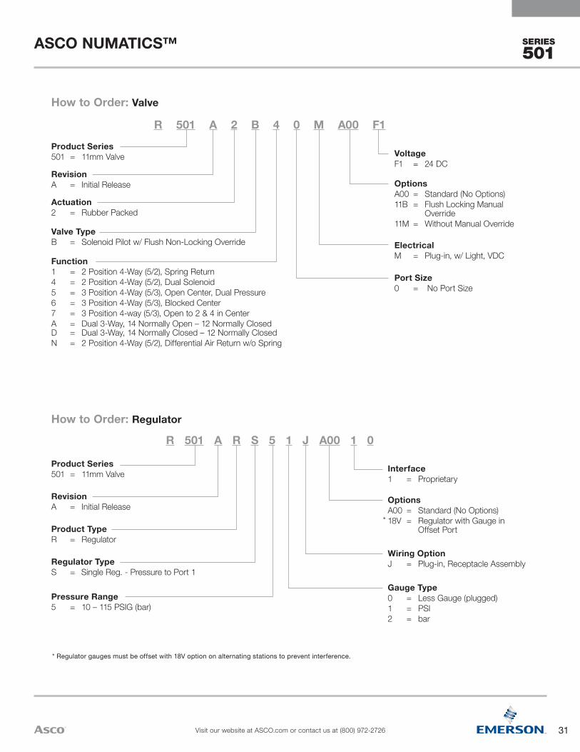
SERIES
501
* Regulator gauges must be offset with 18V option on alternating stations to prevent interference.
Gauge Type0 = Less Gauge (plugged)1 = PSI2 = bar
Wiring OptionJ = Plug-in, Receptacle Assembly
OptionsA00 = Standard (No Options)18V = Regulator with Gauge in
Offset Port*
Interface1 = Proprietary
Pressure Range5 = 10 – 115 PSIG (bar)
Regulator TypeS = Single Reg. - Pressure to Port 1
Product TypeR = Regulator
RevisionA = Initial Release
Product Series501 = 11mm Valve
R 501 A R S 5 1 J A00 1 0
How to Order: Regulator
Port Size0 = No Port Size
ElectricalM = Plug-in, w/ Light, VDC
OptionsA00 = Standard (No Options)11B = Flush Locking Manual
Override11M = Without Manual Override
VoltageF1 = 24 DC
Function1 = 2 Position 4-Way (5/2), Spring Return4 = 2 Position 4-Way (5/2), Dual Solenoid5 = 3 Position 4-Way (5/3), Open Center, Dual Pressure6 = 3 Position 4-Way (5/3), Blocked Center7 = 3 Position 4-way (5/3), Open to 2 & 4 in CenterA = Dual 3-Way, 14 Normally Open – 12 Normally Closed D = Dual 3-Way, 14 Normally Closed – 12 Normally ClosedN = 2 Position 4-Way (5/2), Differential Air Return w/o Spring
Valve TypeB = Solenoid Pilot w/ Flush Non-Locking Override
Actuation2 = Rubber Packed
RevisionA = Initial Release
Product Series501 = 11mm Valve
R 501 A 2 B 4 0 M A00 F1
How to Order: Valve
31
ASCO NUMATICS™
Visit our website at ASCO.com or contact us at (800) 972-2726
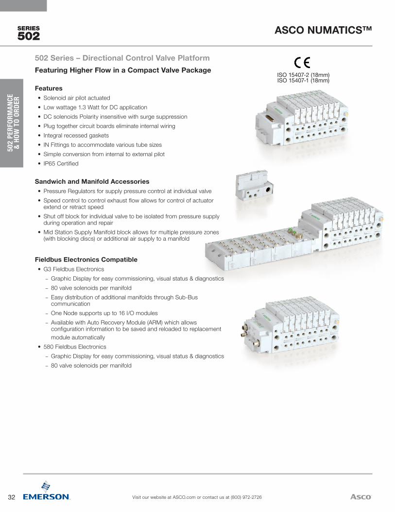
32
ASCO NUMATICS™
Visit our website at ASCO.com or contact us at (800) 972-2726
SERIES
502
502
PERF
ORM
ANCE
&
HOW
TO
ORDE
R
Fieldbus Electronics Compatible• G3 Fieldbus Electronics
– Graphic Display for easy commissioning, visual status & diagnostics – 80 valve solenoids per manifold – Easy distribution of additional manifolds through Sub-Bus communication
– One Node supports up to 16 I/O modules – Available with Auto Recovery Module (ARM) which allows configuration information to be saved and reloaded to replacement module automatically
• 580 Fieldbus Electronics – Graphic Display for easy commissioning, visual status & diagnostics – 80 valve solenoids per manifold
Sandwich and Manifold Accessories• Pressure Regulators for supply pressure control at individual valve• Speed control to control exhaust flow allows for control of actuator
extend or retract speed• Shut off block for individual valve to be isolated from pressure supply
during operation and repair• Mid Station Supply Manifold block allows for multiple pressure zones
(with blocking discs) or additional air supply to a manifold
Features• Solenoid air pilot actuated• Low wattage 1.3 Watt for DC application• DC solenoids Polarity insensitive with surge suppression• Plug together circuit boards eliminate internal wiring• Integral recessed gaskets• IN Fittings to accommodate various tube sizes • Simple conversion from internal to external pilot• IP65 Certified
ISO 15407-2 (18mm)ISO 15407-1 (18mm)
502 Series – Directional Control Valve PlatformFeaturing Higher Flow in a Compact Valve Package

33
ASCO NUMATICS™
Visit our website at ASCO.com or contact us at (800) 972-2726
SERIES
502
All Solenoids Are Continuous Duty Rated 24 VDCPower (Watts) 1.3
Holding Current (Amps) 0.054
Ambient Temperature Range Min/Max °F (°C) -14 °F (-10 °C)/122 °F (50 °C)
Operating DataMaterials in Contact w/Fluid
Body Aluminum, E-Coating treatment
Spool Aluminum or Stainless Steel
Piston POM
Spring Steel
Spool Seals NBR + PUR
Other Seals NBR + FKM
Other materials PAM (Polyarylamide) 50% Glass Fiber Reinforced
Valve to Subbase Gasket NBR
Subbases Aluminum, E-Coating treatment
Construction
Function Type
Function Code
ISO Symbol
Pilot (14) Return (12)
Interface
Rated Flow Response Time (ms)
Pilot Pressure at 73°F/23°C
PSI (bar)
Operating Pressure
Port 1 PSI (bar)/inHg (-bar)
at 90 PSI Cv
(l/min (ANR))1 2 1 4
2 3 4 5
Energize/De-Energize min. max min. max Part Number
Rubber Packed Technology, with Manual Override
2 x 3/2 NC BD
1
4 2
35 1
4 2
3514
14 1
4 2
35
12
1
4 2
35
14 1
4 2
351
4 2
35
14
14
14
1
4 2
35 1
4 2
3514
14 1
4 2
35
12
1
4 2
35
14 1
4 2
351
4 2
35
14
14
14
SYMBOLES PNEUMATIQUES DISTRIBUTEUR 5/2
5/2 PNEUMATIC SYMBOLS
83(12)
004A1
004A3
004A5
004A6
004A8
004A10
004F1
004F3
004F5
004F6
004F8
004F10
14 1
4 2
351
4 2
35 83(12)
14 12
14 1
4 2
351
4 2
35
1214
004A14 004F14
004A15 004F15
SYMBOLES PNEUMATIQUES DISTRIBUTEUR 5/2 - VERSION METAL METAL
5/2 PNEUMATIC SYMBOLS - SPOOL AND SLEEVE VERSION
1
4 2
3514 1
4 2
35
14
1
4 2
3514 1
4 2
35
14
1
4 2
3514 1
4 2
35
14
1
4 2
3514 1
4 2
35
1
4 2
3514 1
4 2
35
1
4 2
3514 1
4 2
35
14
14
14
005A1 005F1
005A2 005F2
005A3 005F3
005A4 005F4
005A5 005F5
005A6 005F6
5
4
5
3
3
2
5
3
3
5
14 12
14 10
10 10
10 12
5
5
3
3
5
3
3
5
14 12
14 10
10 10
10 12
10 10 10 10
10 12 10 12
14 12 14 12
14 10 14 10
5
5
3
3
5
3
3
5
14 12
14 10
10 10
10 12
5
5
3
3
5
3
3
5
14 12
14 10
10 10
10 12
10 10 10 10
10 12 10 12
14 12 14 12
14 10 14 10
1
006A9 006F9
006A10 006F10
006A11 006F11
006A12 006F12
006A13 006F13
006A14 006F14
006A15 006F15
006A16 006F16
1
1
1
1
1
1
1
1
1
1
1
1
1
1
1
83(12)
4 2
4 2
4 2
4 2
4 2
4 2
4 2
4 2
4 2
4 2
4 2
4 2
4 2
4 2
4 2
SYMBOLES PNEUMATIQUES DISTRIBUTEUR 5/3
5/3 PNEUMATIC SYMBOLS
SYMBOLES PNEUMATIQUES DISTRIBUTEUR 2X 3/2
2X 3/2 PNEUMATIC SYMBOLS
83(12)
14
14
14
14
14
14
14
14
83(12)
83(12)
83(12)
83(12)
83(12)
83(12)
83(12)
83(12)
83(12)
83(12)
83(12)
83(12)
83(12)
83(12)
83(12)
83(12)
83(12)
83(12)
83(12)
83(12)
83(12)
83(12)
83(12)
83(12)
83(12)
83(12)
83(12)
83(12)
83(12)
83(12)
83(12)
83(12)
83(12)
83(12)
83(12)
83(12)
83(12)
83(12)
83(12)
83(12)
005A7 005F7
005A8 005F8
SYMBOLES PNEUMATIQUES DISTRIBUTEUR 5/3 W2 - VERSION METAL METAL
5/3 W2 PNEUMATIC SYMBOLS - SPOOL AND SLEEVE VERSION
NOTA / NOTE:SYMBOLES SELON LES NORMES ISO NF ISO 1219-1 Janvier 2007SYMBOLS AS PER ISO NF ISO 1219-1 January 2007
(A)
1483
(12)1
4 2
35
1483
(12)1
4 2
35
14
83(12)
1
4 2
35
14
83(12)
1
4 2
35
√
Normally Closed
Proprietary 0.650(650)
0.600 (600)
36/15 58(4.0)
115(8)
36*(2)
115(8) R502A2BD0MA00F1
ISO 0.500 (500)
0.440 (440)
Spool and Sleeve Technology, with Manual Override
5/2
B1
1
4 2
35 1
4 2
3514
14 1
4 2
35
12
1
4 2
35
14 1
4 2
351
4 2
35
14
14
14
1
4 2
35 1
4 2
3514
14 1
4 2
35
12
1
4 2
35
14 1
4 2
351
4 2
35
14
14
14
SYMBOLES PNEUMATIQUES DISTRIBUTEUR 5/2
5/2 PNEUMATIC SYMBOLS
83(12)
004A1
004A3
004A5
004A6
004A8
004A10
004F1
004F3
004F5
004F6
004F8
004F10
14 1
4 2
351
4 2
35 83(12)
14 12
14 1
4 2
351
4 2
35
1214
004A14 004F14
004A15 004F15
SYMBOLES PNEUMATIQUES DISTRIBUTEUR 5/2 - VERSION METAL METAL
5/2 PNEUMATIC SYMBOLS - SPOOL AND SLEEVE VERSION
1
4 2
3514 1
4 2
35
14
1
4 2
3514 1
4 2
35
14
1
4 2
3514 1
4 2
35
14
1
4 2
3514 1
4 2
35
1
4 2
3514 1
4 2
35
1
4 2
3514 1
4 2
35
14
14
14
005A1 005F1
005A2 005F2
005A3 005F3
005A4 005F4
005A5 005F5
005A6 005F6
5
4
5
3
3
2
5
3
3
5
14 12
14 10
10 10
10 12
5
5
3
3
5
3
3
5
14 12
14 10
10 10
10 12
10 10 10 10
10 12 10 12
14 12 14 12
14 10 14 10
5
5
3
3
5
3
3
5
14 12
14 10
10 10
10 12
5
5
3
3
5
3
3
5
14 12
14 10
10 10
10 12
10 10 10 10
10 12 10 12
14 12 14 12
14 10 14 10
1
006A9 006F9
006A10 006F10
006A11 006F11
006A12 006F12
006A13 006F13
006A14 006F14
006A15 006F15
006A16 006F16
1
1
1
1
1
1
1
1
1
1
1
1
1
1
1
83(12)
4 2
4 2
4 2
4 2
4 2
4 2
4 2
4 2
4 2
4 2
4 2
4 2
4 2
4 2
4 2
SYMBOLES PNEUMATIQUES DISTRIBUTEUR 5/3
5/3 PNEUMATIC SYMBOLS
SYMBOLES PNEUMATIQUES DISTRIBUTEUR 2X 3/2
2X 3/2 PNEUMATIC SYMBOLS
83(12)
14
14
14
14
14
14
14
14
83(12)
83(12)
83(12)
83(12)
83(12)
83(12)
83(12)
83(12)
83(12)
83(12)
83(12)
83(12)
83(12)
83(12)
83(12)
83(12)
83(12)
83(12)
83(12)
83(12)
83(12)
83(12)
83(12)
83(12)
83(12)
83(12)
83(12)
83(12)
83(12)
83(12)
83(12)
83(12)
83(12)
83(12)
83(12)
83(12)
83(12)
83(12)
83(12)
83(12)
005A7 005F7
005A8 005F8
SYMBOLES PNEUMATIQUES DISTRIBUTEUR 5/3 W2 - VERSION METAL METAL
5/3 W2 PNEUMATIC SYMBOLS - SPOOL AND SLEEVE VERSION
NOTA / NOTE:SYMBOLES SELON LES NORMES ISO NF ISO 1219-1 Janvier 2007SYMBOLS AS PER ISO NF ISO 1219-1 January 2007
(A)
1483
(12)1
4 2
35
1483
(12)1
4 2
35
14
83(12)
1
4 2
35
14
83(12)
1
4 2
35
√
Spring Return
Proprietary 0.470 (470)
0.530 (530)
16/49 29 (2)
115 (8)
28 (-0.95)
115 (8) R502A1B10MA00F1
ISO 0.410 (410)
0.390 (390)
BN 1
4 2
35 1
4 2
3514
14 1
4 2
35
12
1
4 2
35
14 1
4 2
351
4 2
35
14
14
14
1
4 2
35 1
4 2
3514
14 1
4 2
35
12
1
4 2
35
14 1
4 2
351
4 2
35
14
14
14
SYMBOLES PNEUMATIQUES DISTRIBUTEUR 5/2
5/2 PNEUMATIC SYMBOLS
83(12)
004A1
004A3
004A5
004A6
004A8
004A10
004F1
004F3
004F5
004F6
004F8
004F10
14 1
4 2
351
4 2
35 83(12)
14 12
14 1
4 2
351
4 2
35
1214
004A14 004F14
004A15 004F15
SYMBOLES PNEUMATIQUES DISTRIBUTEUR 5/2 - VERSION METAL METAL
5/2 PNEUMATIC SYMBOLS - SPOOL AND SLEEVE VERSION
1
4 2
3514 1
4 2
35
14
1
4 2
3514 1
4 2
35
14
1
4 2
3514 1
4 2
35
14
1
4 2
3514 1
4 2
35
1
4 2
3514 1
4 2
35
1
4 2
3514 1
4 2
35
14
14
14
005A1 005F1
005A2 005F2
005A3 005F3
005A4 005F4
005A5 005F5
005A6 005F6
5
4
5
3
3
2
5
3
3
5
14 12
14 10
10 10
10 12
5
5
3
3
5
3
3
5
14 12
14 10
10 10
10 12
10 10 10 10
10 12 10 12
14 12 14 12
14 10 14 10
5
5
3
3
5
3
3
5
14 12
14 10
10 10
10 12
5
5
3
3
5
3
3
5
14 12
14 10
10 10
10 12
10 10 10 10
10 12 10 12
14 12 14 12
14 10 14 10
1
006A9 006F9
006A10 006F10
006A11 006F11
006A12 006F12
006A13 006F13
006A14 006F14
006A15 006F15
006A16 006F16
1
1
1
1
1
1
1
1
1
1
1
1
1
1
1
83(12)
4 2
4 2
4 2
4 2
4 2
4 2
4 2
4 2
4 2
4 2
4 2
4 2
4 2
4 2
4 2
SYMBOLES PNEUMATIQUES DISTRIBUTEUR 5/3
5/3 PNEUMATIC SYMBOLS
SYMBOLES PNEUMATIQUES DISTRIBUTEUR 2X 3/2
2X 3/2 PNEUMATIC SYMBOLS
83(12)
14
14
14
14
14
14
14
14
83(12)
83(12)
83(12)
83(12)
83(12)
83(12)
83(12)
83(12)
83(12)
83(12)
83(12)
83(12)
83(12)
83(12)
83(12)
83(12)
83(12)
83(12)
83(12)
83(12)
83(12)
83(12)
83(12)
83(12)
83(12)
83(12)
83(12)
83(12)
83(12)
83(12)
83(12)
83(12)
83(12)
83(12)
83(12)
83(12)
83(12)
83(12)
83(12)
83(12)
005A7 005F7
005A8 005F8
SYMBOLES PNEUMATIQUES DISTRIBUTEUR 5/3 W2 - VERSION METAL METAL
5/3 W2 PNEUMATIC SYMBOLS - SPOOL AND SLEEVE VERSION
NOTA / NOTE:SYMBOLES SELON LES NORMES ISO NF ISO 1219-1 Janvier 2007SYMBOLS AS PER ISO NF ISO 1219-1 January 2007
(A)
1483
(12)1
4 2
35
1483
(12)1
4 2
35
14
83(12)
1
4 2
35
14
83(12)
1
4 2
35
√
Differential Air Return
Proprietary 0.470 (470)
0.530 (530)
11/26 22 (1.5)
115 (8)
28 (-0.95)
115 (8) R502A1BN0MA00F1
ISO 0.410 (410)
0.390 (390)
B4
1
4 2
35 1
4 2
3514
14 1
4 2
35
12
1
4 2
35
14 1
4 2
351
4 2
35
14
14
14
1
4 2
35 1
4 2
3514
14 1
4 2
35
12
1
4 2
35
14 1
4 2
351
4 2
35
14
14
14
SYMBOLES PNEUMATIQUES DISTRIBUTEUR 5/2
5/2 PNEUMATIC SYMBOLS
83(12)
004A1
004A3
004A5
004A6
004A8
004A10
004F1
004F3
004F5
004F6
004F8
004F10
14 1
4 2
351
4 2
35 83(12)
14 12
14 1
4 2
351
4 2
35
1214
004A14 004F14
004A15 004F15
SYMBOLES PNEUMATIQUES DISTRIBUTEUR 5/2 - VERSION METAL METAL
5/2 PNEUMATIC SYMBOLS - SPOOL AND SLEEVE VERSION
1
4 2
3514 1
4 2
35
14
1
4 2
3514 1
4 2
35
14
1
4 2
3514 1
4 2
35
14
1
4 2
3514 1
4 2
35
1
4 2
3514 1
4 2
35
1
4 2
3514 1
4 2
35
14
14
14
005A1 005F1
005A2 005F2
005A3 005F3
005A4 005F4
005A5 005F5
005A6 005F6
5
4
5
3
3
2
5
3
3
5
14 12
14 10
10 10
10 12
5
5
3
3
5
3
3
5
14 12
14 10
10 10
10 12
10 10 10 10
10 12 10 12
14 12 14 12
14 10 14 10
5
5
3
3
5
3
3
5
14 12
14 10
10 10
10 12
5
5
3
3
5
3
3
5
14 12
14 10
10 10
10 12
10 10 10 10
10 12 10 12
14 12 14 12
14 10 14 10
1
006A9 006F9
006A10 006F10
006A11 006F11
006A12 006F12
006A13 006F13
006A14 006F14
006A15 006F15
006A16 006F16
1
1
1
1
1
1
1
1
1
1
1
1
1
1
1
83(12)
4 2
4 2
4 2
4 2
4 2
4 2
4 2
4 2
4 2
4 2
4 2
4 2
4 2
4 2
4 2
SYMBOLES PNEUMATIQUES DISTRIBUTEUR 5/3
5/3 PNEUMATIC SYMBOLS
SYMBOLES PNEUMATIQUES DISTRIBUTEUR 2X 3/2
2X 3/2 PNEUMATIC SYMBOLS
83(12)
14
14
14
14
14
14
14
14
83(12)
83(12)
83(12)
83(12)
83(12)
83(12)
83(12)
83(12)
83(12)
83(12)
83(12)
83(12)
83(12)
83(12)
83(12)
83(12)
83(12)
83(12)
83(12)
83(12)
83(12)
83(12)
83(12)
83(12)
83(12)
83(12)
83(12)
83(12)
83(12)
83(12)
83(12)
83(12)
83(12)
83(12)
83(12)
83(12)
83(12)
83(12)
83(12)
83(12)
005A7 005F7
005A8 005F8
SYMBOLES PNEUMATIQUES DISTRIBUTEUR 5/3 W2 - VERSION METAL METAL
5/3 W2 PNEUMATIC SYMBOLS - SPOOL AND SLEEVE VERSION
NOTA / NOTE:SYMBOLES SELON LES NORMES ISO NF ISO 1219-1 Janvier 2007SYMBOLS AS PER ISO NF ISO 1219-1 January 2007
(A)
1483
(12)1
4 2
35
1483
(12)1
4 2
35
14
83(12)
1
4 2
35
14
83(12)
1
4 2
35
√
Solenoid Air Return
Proprietary 0.470 (470)
0.530 (530)
12/15 29 (2)
115 (8)
28 (-0.95)
115 (8) R502A1B40MA00F1
ISO 0.410 (410)
0.390 (390)
5/3
B5
1
4 2
35 1
4 2
3514
14 1
4 2
35
12
1
4 2
35
14 1
4 2
351
4 2
35
14
14
14
1
4 2
35 1
4 2
3514
14 1
4 2
35
12
1
4 2
35
14 1
4 2
351
4 2
35
14
14
14
SYMBOLES PNEUMATIQUES DISTRIBUTEUR 5/2
5/2 PNEUMATIC SYMBOLS
83(12)
004A1
004A3
004A5
004A6
004A8
004A10
004F1
004F3
004F5
004F6
004F8
004F10
14 1
4 2
351
4 2
35 83(12)
14 12
14 1
4 2
351
4 2
35
1214
004A14 004F14
004A15 004F15
SYMBOLES PNEUMATIQUES DISTRIBUTEUR 5/2 - VERSION METAL METAL
5/2 PNEUMATIC SYMBOLS - SPOOL AND SLEEVE VERSION
1
4 2
3514 1
4 2
35
14
1
4 2
3514 1
4 2
35
14
1
4 2
3514 1
4 2
35
14
1
4 2
3514 1
4 2
35
1
4 2
3514 1
4 2
35
1
4 2
3514 1
4 2
35
14
14
14
005A1 005F1
005A2 005F2
005A3 005F3
005A4 005F4
005A5 005F5
005A6 005F6
5
4
5
3
3
2
5
3
3
5
14 12
14 10
10 10
10 12
5
5
3
3
5
3
3
5
14 12
14 10
10 10
10 12
10 10 10 10
10 12 10 12
14 12 14 12
14 10 14 10
5
5
3
3
5
3
3
5
14 12
14 10
10 10
10 12
5
5
3
3
5
3
3
5
14 12
14 10
10 10
10 12
10 10 10 10
10 12 10 12
14 12 14 12
14 10 14 10
1
006A9 006F9
006A10 006F10
006A11 006F11
006A12 006F12
006A13 006F13
006A14 006F14
006A15 006F15
006A16 006F16
1
1
1
1
1
1
1
1
1
1
1
1
1
1
1
83(12)
4 2
4 2
4 2
4 2
4 2
4 2
4 2
4 2
4 2
4 2
4 2
4 2
4 2
4 2
4 2
SYMBOLES PNEUMATIQUES DISTRIBUTEUR 5/3
5/3 PNEUMATIC SYMBOLS
SYMBOLES PNEUMATIQUES DISTRIBUTEUR 2X 3/2
2X 3/2 PNEUMATIC SYMBOLS
83(12)
14
14
14
14
14
14
14
14
83(12)
83(12)
83(12)
83(12)
83(12)
83(12)
83(12)
83(12)
83(12)
83(12)
83(12)
83(12)
83(12)
83(12)
83(12)
83(12)
83(12)
83(12)
83(12)
83(12)
83(12)
83(12)
83(12)
83(12)
83(12)
83(12)
83(12)
83(12)
83(12)
83(12)
83(12)
83(12)
83(12)
83(12)
83(12)
83(12)
83(12)
83(12)
83(12)
83(12)
005A7 005F7
005A8 005F8
SYMBOLES PNEUMATIQUES DISTRIBUTEUR 5/3 W2 - VERSION METAL METAL
5/3 W2 PNEUMATIC SYMBOLS - SPOOL AND SLEEVE VERSION
NOTA / NOTE:SYMBOLES SELON LES NORMES ISO NF ISO 1219-1 Janvier 2007SYMBOLS AS PER ISO NF ISO 1219-1 January 2007
(A)
1483
(12)1
4 2
35
1483
(12)1
4 2
35
14
83(12)
1
4 2
35
14
83(12)
1
4 2
35
√
Center Open to Exhaust
Proprietary 0.380 (380)
0.500 (500)
23/13 22 (1.5)
115 (8)
28 (-0.95)
115 (8) R502A1B50MA00F1
ISO 0.340 (340)
0.350 (350)
B61
4 2
35 1
4 2
3514
14 1
4 2
35
12
1
4 2
35
14 1
4 2
351
4 2
35
14
14
14
1
4 2
35 1
4 2
3514
14 1
4 2
35
12
1
4 2
35
14 1
4 2
351
4 2
35
14
14
14
SYMBOLES PNEUMATIQUES DISTRIBUTEUR 5/2
5/2 PNEUMATIC SYMBOLS
83(12)
004A1
004A3
004A5
004A6
004A8
004A10
004F1
004F3
004F5
004F6
004F8
004F10
14 1
4 2
351
4 2
35 83(12)
14 12
14 1
4 2
351
4 2
35
1214
004A14 004F14
004A15 004F15
SYMBOLES PNEUMATIQUES DISTRIBUTEUR 5/2 - VERSION METAL METAL
5/2 PNEUMATIC SYMBOLS - SPOOL AND SLEEVE VERSION
1
4 2
3514 1
4 2
35
14
1
4 2
3514 1
4 2
35
14
1
4 2
3514 1
4 2
35
14
1
4 2
3514 1
4 2
35
1
4 2
3514 1
4 2
35
1
4 2
3514 1
4 2
35
14
14
14
005A1 005F1
005A2 005F2
005A3 005F3
005A4 005F4
005A5 005F5
005A6 005F6
5
4
5
3
3
2
5
3
3
5
14 12
14 10
10 10
10 12
5
5
3
3
5
3
3
5
14 12
14 10
10 10
10 12
10 10 10 10
10 12 10 12
14 12 14 12
14 10 14 10
5
5
3
3
5
3
3
5
14 12
14 10
10 10
10 12
5
5
3
3
5
3
3
5
14 12
14 10
10 10
10 12
10 10 10 10
10 12 10 12
14 12 14 12
14 10 14 10
1
006A9 006F9
006A10 006F10
006A11 006F11
006A12 006F12
006A13 006F13
006A14 006F14
006A15 006F15
006A16 006F16
1
1
1
1
1
1
1
1
1
1
1
1
1
1
1
83(12)
4 2
4 2
4 2
4 2
4 2
4 2
4 2
4 2
4 2
4 2
4 2
4 2
4 2
4 2
4 2
SYMBOLES PNEUMATIQUES DISTRIBUTEUR 5/3
5/3 PNEUMATIC SYMBOLS
SYMBOLES PNEUMATIQUES DISTRIBUTEUR 2X 3/2
2X 3/2 PNEUMATIC SYMBOLS
83(12)
14
14
14
14
14
14
14
14
83(12)
83(12)
83(12)
83(12)
83(12)
83(12)
83(12)
83(12)
83(12)
83(12)
83(12)
83(12)
83(12)
83(12)
83(12)
83(12)
83(12)
83(12)
83(12)
83(12)
83(12)
83(12)
83(12)
83(12)
83(12)
83(12)
83(12)
83(12)
83(12)
83(12)
83(12)
83(12)
83(12)
83(12)
83(12)
83(12)
83(12)
83(12)
83(12)
83(12)
005A7 005F7
005A8 005F8
SYMBOLES PNEUMATIQUES DISTRIBUTEUR 5/3 W2 - VERSION METAL METAL
5/3 W2 PNEUMATIC SYMBOLS - SPOOL AND SLEEVE VERSION
NOTA / NOTE:SYMBOLES SELON LES NORMES ISO NF ISO 1219-1 Janvier 2007SYMBOLS AS PER ISO NF ISO 1219-1 January 2007
(A)
1483
(12)1
4 2
35
1483
(12)1
4 2
35
14
83(12)
1
4 2
35
14
83(12)
1
4 2
35
√
Center Closed
Proprietary 0.420 (420)
0.440 (440)
12/12 22 (1.5)
115 (8)
28 (-0.95)
115 (8) R502A1B60MA00F1
ISO 0.360 (360)
0.350 (350)
B7
1
4 2
35 1
4 2
3514
14 1
4 2
35
12
1
4 2
35
14 1
4 2
351
4 2
35
14
14
14
1
4 2
35 1
4 2
3514
14 1
4 2
35
12
1
4 2
35
14 1
4 2
351
4 2
35
14
14
14
SYMBOLES PNEUMATIQUES DISTRIBUTEUR 5/2
5/2 PNEUMATIC SYMBOLS
83(12)
004A1
004A3
004A5
004A6
004A8
004A10
004F1
004F3
004F5
004F6
004F8
004F10
14 1
4 2
351
4 2
35 83(12)
14 12
14 1
4 2
351
4 2
35
1214
004A14 004F14
004A15 004F15
SYMBOLES PNEUMATIQUES DISTRIBUTEUR 5/2 - VERSION METAL METAL
5/2 PNEUMATIC SYMBOLS - SPOOL AND SLEEVE VERSION
1
4 2
3514 1
4 2
35
14
1
4 2
3514 1
4 2
35
14
1
4 2
3514 1
4 2
35
14
1
4 2
3514 1
4 2
35
1
4 2
3514 1
4 2
35
1
4 2
3514 1
4 2
35
14
14
14
005A1 005F1
005A2 005F2
005A3 005F3
005A4 005F4
005A5 005F5
005A6 005F6
5
4
5
3
3
2
5
3
3
5
14 12
14 10
10 10
10 12
5
5
3
3
5
3
3
5
14 12
14 10
10 10
10 12
10 10 10 10
10 12 10 12
14 12 14 12
14 10 14 10
5
5
3
3
5
3
3
5
14 12
14 10
10 10
10 12
5
5
3
3
5
3
3
5
14 12
14 10
10 10
10 12
10 10 10 10
10 12 10 12
14 12 14 12
14 10 14 10
1
006A9 006F9
006A10 006F10
006A11 006F11
006A12 006F12
006A13 006F13
006A14 006F14
006A15 006F15
006A16 006F16
1
1
1
1
1
1
1
1
1
1
1
1
1
1
1
83(12)
4 2
4 2
4 2
4 2
4 2
4 2
4 2
4 2
4 2
4 2
4 2
4 2
4 2
4 2
4 2
SYMBOLES PNEUMATIQUES DISTRIBUTEUR 5/3
5/3 PNEUMATIC SYMBOLS
SYMBOLES PNEUMATIQUES DISTRIBUTEUR 2X 3/2
2X 3/2 PNEUMATIC SYMBOLS
83(12)
14
14
14
14
14
14
14
14
83(12)
83(12)
83(12)
83(12)
83(12)
83(12)
83(12)
83(12)
83(12)
83(12)
83(12)
83(12)
83(12)
83(12)
83(12)
83(12)
83(12)
83(12)
83(12)
83(12)
83(12)
83(12)
83(12)
83(12)
83(12)
83(12)
83(12)
83(12)
83(12)
83(12)
83(12)
83(12)
83(12)
83(12)
83(12)
83(12)
83(12)
83(12)
83(12)
83(12)
005A7 005F7
005A8 005F8
SYMBOLES PNEUMATIQUES DISTRIBUTEUR 5/3 W2 - VERSION METAL METAL
5/3 W2 PNEUMATIC SYMBOLS - SPOOL AND SLEEVE VERSION
NOTA / NOTE:SYMBOLES SELON LES NORMES ISO NF ISO 1219-1 Janvier 2007SYMBOLS AS PER ISO NF ISO 1219-1 January 2007
(A)
1483
(12)1
4 2
35
1483
(12)1
4 2
35
14
83(12)
1
4 2
35
14
83(12)
1
4 2
35
√
Center Open to Pressure
Proprietary 0.420 (420)
0.430 (430)
13/23 22 (1.5)
115 (8)
28 (-0.95)
115 (8) R502A1B70MA00F1
ISO 0.370 (370)
0.350 (350)
* Minimum pressure with external piloting
Performance Data
1
4 2
35 1
4 2
3514
14 1
4 2
35
12
1
4 2
35
14 1
4 2
351
4 2
35
14
14
14
1
4 2
35 1
4 2
3514
14 1
4 2
35
12
1
4 2
35
14 1
4 2
351
4 2
35
14
14
14
SYMBOLES PNEUMATIQUES DISTRIBUTEUR 5/2
5/2 PNEUMATIC SYMBOLS
83(12)
004A1
004A3
004A5
004A6
004A8
004A10
004F1
004F3
004F5
004F6
004F8
004F10
14 1
4 2
351
4 2
35 83(12)
14 12
14 1
4 2
351
4 2
35
1214
004A14 004F14
004A15 004F15
SYMBOLES PNEUMATIQUES DISTRIBUTEUR 5/2 - VERSION METAL METAL
5/2 PNEUMATIC SYMBOLS - SPOOL AND SLEEVE VERSION
1
4 2
3514 1
4 2
35
14
1
4 2
3514 1
4 2
35
14
1
4 2
3514 1
4 2
35
14
1
4 2
3514 1
4 2
35
1
4 2
3514 1
4 2
35
1
4 2
3514 1
4 2
35
14
14
14
005A1 005F1
005A2 005F2
005A3 005F3
005A4 005F4
005A5 005F5
005A6 005F6
5
4
5
3
3
2
5
3
3
5
14 12
14 10
10 10
10 12
5
5
3
3
5
3
3
5
14 12
14 10
10 10
10 12
10 10 10 10
10 12 10 12
14 12 14 12
14 10 14 10
5
5
3
3
5
3
3
5
14 12
14 10
10 10
10 12
5
5
3
3
5
3
3
5
14 12
14 10
10 10
10 12
10 10 10 10
10 12 10 12
14 12 14 12
14 10 14 10
1
006A9 006F9
006A10 006F10
006A11 006F11
006A12 006F12
006A13 006F13
006A14 006F14
006A15 006F15
006A16 006F16
1
1
1
1
1
1
1
1
1
1
1
1
1
1
1
83(12)
4 2
4 2
4 2
4 2
4 2
4 2
4 2
4 2
4 2
4 2
4 2
4 2
4 2
4 2
4 2
SYMBOLES PNEUMATIQUES DISTRIBUTEUR 5/3
5/3 PNEUMATIC SYMBOLS
SYMBOLES PNEUMATIQUES DISTRIBUTEUR 2X 3/2
2X 3/2 PNEUMATIC SYMBOLS
83(12)
14
14
14
14
14
14
14
14
83(12)
83(12)
83(12)
83(12)
83(12)
83(12)
83(12)
83(12)
83(12)
83(12)
83(12)
83(12)
83(12)
83(12)
83(12)
83(12)
83(12)
83(12)
83(12)
83(12)
83(12)
83(12)
83(12)
83(12)
83(12)
83(12)
83(12)
83(12)
83(12)
83(12)
83(12)
83(12)
83(12)
83(12)
83(12)
83(12)
83(12)
83(12)
83(12)
83(12)
005A7 005F7
005A8 005F8
SYMBOLES PNEUMATIQUES DISTRIBUTEUR 5/3 W2 - VERSION METAL METAL
5/3 W2 PNEUMATIC SYMBOLS - SPOOL AND SLEEVE VERSION
NOTA / NOTE:SYMBOLES SELON LES NORMES ISO NF ISO 1219-1 Janvier 2007SYMBOLS AS PER ISO NF ISO 1219-1 January 2007
(A)
1483
(12)1
4 2
35
1483
(12)1
4 2
35
14
83(12)
1
4 2
35
14
83(12)
1
4 2
35
√
1
4 2
35 1
4 2
3514
14 1
4 2
35
12
1
4 2
35
14 1
4 2
351
4 2
35
14
14
14
1
4 2
35 1
4 2
3514
14 1
4 2
35
12
1
4 2
35
14 1
4 2
351
4 2
35
14
14
14
SYMBOLES PNEUMATIQUES DISTRIBUTEUR 5/2
5/2 PNEUMATIC SYMBOLS
83(12)
004A1
004A3
004A5
004A6
004A8
004A10
004F1
004F3
004F5
004F6
004F8
004F10
14 1
4 2
351
4 2
35 83(12)
14 12
14 1
4 2
351
4 2
35
1214
004A14 004F14
004A15 004F15
SYMBOLES PNEUMATIQUES DISTRIBUTEUR 5/2 - VERSION METAL METAL
5/2 PNEUMATIC SYMBOLS - SPOOL AND SLEEVE VERSION
1
4 2
3514 1
4 2
35
14
1
4 2
3514 1
4 2
35
14
1
4 2
3514 1
4 2
35
14
1
4 2
3514 1
4 2
35
1
4 2
3514 1
4 2
35
1
4 2
3514 1
4 2
35
14
14
14
005A1 005F1
005A2 005F2
005A3 005F3
005A4 005F4
005A5 005F5
005A6 005F6
5
4
5
3
3
2
5
3
3
5
14 12
14 10
10 10
10 12
5
5
3
3
5
3
3
5
14 12
14 10
10 10
10 12
10 10 10 10
10 12 10 12
14 12 14 12
14 10 14 10
5
5
3
3
5
3
3
5
14 12
14 10
10 10
10 12
5
5
3
3
5
3
3
5
14 12
14 10
10 10
10 12
10 10 10 10
10 12 10 12
14 12 14 12
14 10 14 10
1
006A9 006F9
006A10 006F10
006A11 006F11
006A12 006F12
006A13 006F13
006A14 006F14
006A15 006F15
006A16 006F16
1
1
1
1
1
1
1
1
1
1
1
1
1
1
1
83(12)
4 2
4 2
4 2
4 2
4 2
4 2
4 2
4 2
4 2
4 2
4 2
4 2
4 2
4 2
4 2
SYMBOLES PNEUMATIQUES DISTRIBUTEUR 5/3
5/3 PNEUMATIC SYMBOLS
SYMBOLES PNEUMATIQUES DISTRIBUTEUR 2X 3/2
2X 3/2 PNEUMATIC SYMBOLS
83(12)
14
14
14
14
14
14
14
14
83(12)
83(12)
83(12)
83(12)
83(12)
83(12)
83(12)
83(12)
83(12)
83(12)
83(12)
83(12)
83(12)
83(12)
83(12)
83(12)
83(12)
83(12)
83(12)
83(12)
83(12)
83(12)
83(12)
83(12)
83(12)
83(12)
83(12)
83(12)
83(12)
83(12)
83(12)
83(12)
83(12)
83(12)
83(12)
83(12)
83(12)
83(12)
83(12)
83(12)
005A7 005F7
005A8 005F8
SYMBOLES PNEUMATIQUES DISTRIBUTEUR 5/3 W2 - VERSION METAL METAL
5/3 W2 PNEUMATIC SYMBOLS - SPOOL AND SLEEVE VERSION
NOTA / NOTE:SYMBOLES SELON LES NORMES ISO NF ISO 1219-1 Janvier 2007SYMBOLS AS PER ISO NF ISO 1219-1 January 2007
(A)
1483
(12)1
4 2
35
1483
(12)1
4 2
35
14
83(12)
1
4 2
35
14
83(12)
1
4 2
35
√

SERIES
502
* Regulator gauges must be offset with 61Y option on alternating stations to prevent interference.
Gauge Type1 = PSI2 = bar8 = with 1/8" NPTF adaptor for external gaugeG = with 1/8" G tap adaptor for external gauge
Wiring OptionJ = Plug-in, Receptacle Assembly0 = Non Plug-in
OptionsA00 = Standard (No Options)14M = Temperproof Needle Cartridge Assembly or
Regulator16N = Jumper for Supply Pressure to Valve, 14 End16P = Jumper for Supply Pressure to Valve, 12 End61Y = Regulator with Gauge Extension Fitting
*
Interface1 = Proprietary2 = ISO 15407-23 = ISO 15407-1
Pressure Range1 = 10 - 130 PSIG (0.7 - 9 bar)3 = 3 - 30 PSIG (0.2 - 2 bar)4 = 5 - 60 PSIG (0.3 - 4.1 bar)
Regulator TypeS = Single Reg. - Pressure to Port 1 D = Double Reg. - Pressure to Ports 5 & 3E = Double Reg. - Pressure to Ports 4 & 2,
w/o ValveT = Double Reg. - Pressure to Ports 1 & 3,
2 Pressure Selector
Product TypeR = Regulator
RevisionA = Initial Release
Product Series502 = 18mm Valve
R 502 A R S 1 1 J A00 1 0Regulator
4 321
Pin 3 = CommonPin 4 = Coil 14
Pin 1 = Not UsedPin 2 = Coil 12
1 Not available with Function D2 Available with Function D only3 See diagram:
Port Size0 = No Port Size
ElectricalM = Plug-in, w/Light, VDCN = M12 Connector
Pin 1 = Not Used; Pin 2 = Coil 12; Pin 3 = Common; Pin 4 = Coil 14
OptionsA00 = Standard (No Options)11B = Flush Locking Manual Override11M = Without Manual Override
VoltageF1 = 24 DC
Function1 = 2 Position 4-Way (5/2), Spring Return 4 = 2 Position 4-Way (5/2), Dual Solenoid 5 = 3 Position 4-Way (5/3), Open Center, Dual Pressure6 = 3 Position 4-Way (5/3), Blocked Center 7 = 3 Position 4-way (5/3), Open to 2 & 4 in Center D = Dual 3-way, 12 Normally Closed - 14 Normally Closed
Valve TypeB = Solenoid Pilot with Flush Non-Locking Override
3
1 2
Actuation1 = Spool and Sleeve2 = Rubber Packed
RevisionA = Initial Release
Product Series502 = 18mm Valve
R 502 A 1 B 4 0 M A00 F1How to Order: Valve
34
ASCO NUMATICS™
Visit our website at ASCO.com or contact us at (800) 972-2726

35
ASCO NUMATICS™
Visit our website at ASCO.com or contact us at (800) 972-2726
SERIES
503
503 PERFORMANCE
& HOW TO ORDER
ISO 15407-2 (26mm)ISO 15407-1 (26mm)
All Solenoids Are Continuous Duty Rated 24 VDCPower (Watts) 1.7
Holding Current (Amps) 0.071
Ambient Temperature Range Min/Max °F (°C) -14° F (-10° C)/122° F (50° C)
Operating Data
Materials in Contact w/FluidBody Aluminum, E-Coating treatment
Spool Aluminum or Stainless Steel
Piston POM
Spring Steel
Spool Seals NBR + PUR
Other Seals NBR + FKM
Other materials PAM (Polyarylamide) 50% Glass Fiber Reinforced
Valve to Subbase Gasket NBR
Subbases Aluminum, E-Coating treatment
Construction
Sandwich and Manifold Accessories• Pressure Regulators for supply pressure control at individual valve• Speed control to control exhaust flow allows for control of actuator
extend or retract speed• Shut off block for individual valve to be isolated from pressure
supply during operation and repair• Mid Station Supply Manifold block allows for multiple pressure
zones (with blocking discs) or additional air supply to a manifoldFieldbus Electronics Compatible• G3 Fieldbus Electronics
– Graphic Display for easy commissioning, visual status & diagnostics
– 80 valve solenoids per manifold – Easy distribution of additional manifolds through Sub-Bus communication
– One Node supports up to 16 I/O modules – Available with Auto Recovery Module (ARM) which allows configuration information to be saved and reloaded to replacement module automatically
• 580 Fieldbus Electronics – Graphic Display for easy commissioning, visual status & diagnostics
– 80 valve solenoids per manifold
Features• 5 Ported, 2 and 3 position, 4-way, Spool & Sleeve and Rubber Seal, Cv: 1.2 - 1.4 • Solenoid air pilot actuated• Low wattage 1.7 Watt for DC application• DC solenoids Polarity insensitive with surge suppression• Plug together circuit boards eliminate internal wiring• Integral recessed gaskets• IN Fittings to accommodate various tube sizes • Simple conversion from internal to external pilot• G3 Fieldbus Electronics• IP65 Certified
503 Series – Directional Control Valve PlatformFeaturing Higher Flow in a Compact Valve Package
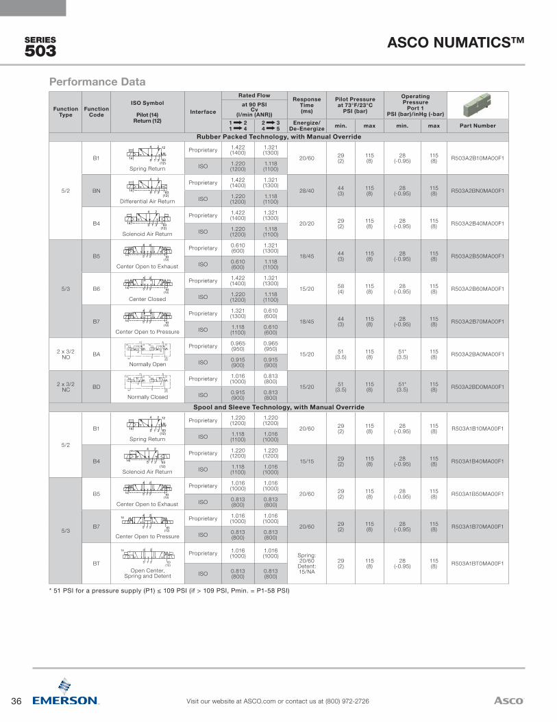
36
ASCO NUMATICS™
Visit our website at ASCO.com or contact us at (800) 972-2726
SERIES
503
Function Type
Function Code
ISO Symbol
Pilot (14) Return (12)
Interface
Rated Flow Response Time (ms)
Pilot Pressure at 73°F/23°C
PSI (bar)
Operating Pressure
Port 1 PSI (bar)/inHg (-bar)
at 90 PSI Cv
(l/min (ANR))1 2 1 4
2 3 4 5
Energize/De-Energize min. max min. max Part Number
Rubber Packed Technology, with Manual Override
5/2
B1
1
4 2
35 1
4 2
3514
14 1
4 2
35
12
1
4 2
35
14 1
4 2
351
4 2
35
14
14
14
1
4 2
35 1
4 2
3514
14 1
4 2
35
12
1
4 2
35
14 1
4 2
351
4 2
35
14
14
14
SYMBOLES PNEUMATIQUES DISTRIBUTEUR 5/2
5/2 PNEUMATIC SYMBOLS
83(12)
004A1
004A3
004A5
004A6
004A8
004A10
004F1
004F3
004F5
004F6
004F8
004F10
14 1
4 2
351
4 2
35 83(12)
14 12
14 1
4 2
351
4 2
35
1214
004A14 004F14
004A15 004F15
SYMBOLES PNEUMATIQUES DISTRIBUTEUR 5/2 - VERSION METAL METAL
5/2 PNEUMATIC SYMBOLS - SPOOL AND SLEEVE VERSION
1
4 2
3514 1
4 2
35
14
1
4 2
3514 1
4 2
35
14
1
4 2
3514 1
4 2
35
14
1
4 2
3514 1
4 2
35
1
4 2
3514 1
4 2
35
1
4 2
3514 1
4 2
35
14
14
14
005A1 005F1
005A2 005F2
005A3 005F3
005A4 005F4
005A5 005F5
005A6 005F6
5
4
5
3
3
2
5
3
3
5
14 12
14 10
10 10
10 12
5
5
3
3
5
3
3
5
14 12
14 10
10 10
10 12
10 10 10 10
10 12 10 12
14 12 14 12
14 10 14 10
5
5
3
3
5
3
3
5
14 12
14 10
10 10
10 12
5
5
3
3
5
3
3
5
14 12
14 10
10 10
10 12
10 10 10 10
10 12 10 12
14 12 14 12
14 10 14 10
1
006A9 006F9
006A10 006F10
006A11 006F11
006A12 006F12
006A13 006F13
006A14 006F14
006A15 006F15
006A16 006F16
1
1
1
1
1
1
1
1
1
1
1
1
1
1
1
83(12)
4 2
4 2
4 2
4 2
4 2
4 2
4 2
4 2
4 2
4 2
4 2
4 2
4 2
4 2
4 2
SYMBOLES PNEUMATIQUES DISTRIBUTEUR 5/3
5/3 PNEUMATIC SYMBOLS
SYMBOLES PNEUMATIQUES DISTRIBUTEUR 2X 3/2
2X 3/2 PNEUMATIC SYMBOLS
83(12)
14
14
14
14
14
14
14
14
83(12)
83(12)
83(12)
83(12)
83(12)
83(12)
83(12)
83(12)
83(12)
83(12)
83(12)
83(12)
83(12)
83(12)
83(12)
83(12)
83(12)
83(12)
83(12)
83(12)
83(12)
83(12)
83(12)
83(12)
83(12)
83(12)
83(12)
83(12)
83(12)
83(12)
83(12)
83(12)
83(12)
83(12)
83(12)
83(12)
83(12)
83(12)
83(12)
83(12)
005A7 005F7
005A8 005F8
SYMBOLES PNEUMATIQUES DISTRIBUTEUR 5/3 W2 - VERSION METAL METAL
5/3 W2 PNEUMATIC SYMBOLS - SPOOL AND SLEEVE VERSION
NOTA / NOTE:SYMBOLES SELON LES NORMES ISO NF ISO 1219-1 Janvier 2007SYMBOLS AS PER ISO NF ISO 1219-1 January 2007
(A)
1483
(12)1
4 2
35
1483
(12)1
4 2
35
14
83(12)
1
4 2
35
14
83(12)
1
4 2
35
√
Spring Return
Proprietary 1.422 (1400)
1.321 (1300)
20/60 29 (2)
115 (8)
28 (-0.95)
115 (8) R503A2B10MA00F1
ISO 1.220 (1200)
1.118 (1100)
BN 1
4 2
35 1
4 2
3514
14 1
4 2
35
12
1
4 2
35
14 1
4 2
351
4 2
35
14
14
14
1
4 2
35 1
4 2
3514
14 1
4 2
35
12
1
4 2
35
14 1
4 2
351
4 2
35
14
14
14
SYMBOLES PNEUMATIQUES DISTRIBUTEUR 5/2
5/2 PNEUMATIC SYMBOLS
83(12)
004A1
004A3
004A5
004A6
004A8
004A10
004F1
004F3
004F5
004F6
004F8
004F10
14 1
4 2
351
4 2
35 83(12)
14 12
14 1
4 2
351
4 2
35
1214
004A14 004F14
004A15 004F15
SYMBOLES PNEUMATIQUES DISTRIBUTEUR 5/2 - VERSION METAL METAL
5/2 PNEUMATIC SYMBOLS - SPOOL AND SLEEVE VERSION
1
4 2
3514 1
4 2
35
14
1
4 2
3514 1
4 2
35
14
1
4 2
3514 1
4 2
35
14
1
4 2
3514 1
4 2
35
1
4 2
3514 1
4 2
35
1
4 2
3514 1
4 2
35
14
14
14
005A1 005F1
005A2 005F2
005A3 005F3
005A4 005F4
005A5 005F5
005A6 005F6
5
4
5
3
3
2
5
3
3
5
14 12
14 10
10 10
10 12
5
5
3
3
5
3
3
5
14 12
14 10
10 10
10 12
10 10 10 10
10 12 10 12
14 12 14 12
14 10 14 10
5
5
3
3
5
3
3
5
14 12
14 10
10 10
10 12
5
5
3
3
5
3
3
5
14 12
14 10
10 10
10 12
10 10 10 10
10 12 10 12
14 12 14 12
14 10 14 10
1
006A9 006F9
006A10 006F10
006A11 006F11
006A12 006F12
006A13 006F13
006A14 006F14
006A15 006F15
006A16 006F16
1
1
1
1
1
1
1
1
1
1
1
1
1
1
1
83(12)
4 2
4 2
4 2
4 2
4 2
4 2
4 2
4 2
4 2
4 2
4 2
4 2
4 2
4 2
4 2
SYMBOLES PNEUMATIQUES DISTRIBUTEUR 5/3
5/3 PNEUMATIC SYMBOLS
SYMBOLES PNEUMATIQUES DISTRIBUTEUR 2X 3/2
2X 3/2 PNEUMATIC SYMBOLS
83(12)
14
14
14
14
14
14
14
14
83(12)
83(12)
83(12)
83(12)
83(12)
83(12)
83(12)
83(12)
83(12)
83(12)
83(12)
83(12)
83(12)
83(12)
83(12)
83(12)
83(12)
83(12)
83(12)
83(12)
83(12)
83(12)
83(12)
83(12)
83(12)
83(12)
83(12)
83(12)
83(12)
83(12)
83(12)
83(12)
83(12)
83(12)
83(12)
83(12)
83(12)
83(12)
83(12)
83(12)
005A7 005F7
005A8 005F8
SYMBOLES PNEUMATIQUES DISTRIBUTEUR 5/3 W2 - VERSION METAL METAL
5/3 W2 PNEUMATIC SYMBOLS - SPOOL AND SLEEVE VERSION
NOTA / NOTE:SYMBOLES SELON LES NORMES ISO NF ISO 1219-1 Janvier 2007SYMBOLS AS PER ISO NF ISO 1219-1 January 2007
(A)
1483
(12)1
4 2
35
1483
(12)1
4 2
35
14
83(12)
1
4 2
35
14
83(12)
1
4 2
35
√
Differential Air Return
Proprietary 1.422 (1400)
1.321 (1300)
28/40 44 (3)
115 (8)
28 (-0.95)
115 (8) R503A2BN0MA00F1
ISO 1.220 (1200)
1.118 (1100)
B4
1
4 2
35 1
4 2
3514
14 1
4 2
35
12
1
4 2
35
14 1
4 2
351
4 2
35
14
14
14
1
4 2
35 1
4 2
3514
14 1
4 2
35
12
1
4 2
35
14 1
4 2
351
4 2
35
14
14
14
SYMBOLES PNEUMATIQUES DISTRIBUTEUR 5/2
5/2 PNEUMATIC SYMBOLS
83(12)
004A1
004A3
004A5
004A6
004A8
004A10
004F1
004F3
004F5
004F6
004F8
004F10
14 1
4 2
351
4 2
35 83(12)
14 12
14 1
4 2
351
4 2
35
1214
004A14 004F14
004A15 004F15
SYMBOLES PNEUMATIQUES DISTRIBUTEUR 5/2 - VERSION METAL METAL
5/2 PNEUMATIC SYMBOLS - SPOOL AND SLEEVE VERSION
1
4 2
3514 1
4 2
35
14
1
4 2
3514 1
4 2
35
14
1
4 2
3514 1
4 2
35
14
1
4 2
3514 1
4 2
35
1
4 2
3514 1
4 2
35
1
4 2
3514 1
4 2
35
14
14
14
005A1 005F1
005A2 005F2
005A3 005F3
005A4 005F4
005A5 005F5
005A6 005F6
5
4
5
3
3
2
5
3
3
5
14 12
14 10
10 10
10 12
5
5
3
3
5
3
3
5
14 12
14 10
10 10
10 12
10 10 10 10
10 12 10 12
14 12 14 12
14 10 14 10
5
5
3
3
5
3
3
5
14 12
14 10
10 10
10 12
5
5
3
3
5
3
3
5
14 12
14 10
10 10
10 12
10 10 10 10
10 12 10 12
14 12 14 12
14 10 14 10
1
006A9 006F9
006A10 006F10
006A11 006F11
006A12 006F12
006A13 006F13
006A14 006F14
006A15 006F15
006A16 006F16
1
1
1
1
1
1
1
1
1
1
1
1
1
1
1
83(12)
4 2
4 2
4 2
4 2
4 2
4 2
4 2
4 2
4 2
4 2
4 2
4 2
4 2
4 2
4 2
SYMBOLES PNEUMATIQUES DISTRIBUTEUR 5/3
5/3 PNEUMATIC SYMBOLS
SYMBOLES PNEUMATIQUES DISTRIBUTEUR 2X 3/2
2X 3/2 PNEUMATIC SYMBOLS
83(12)
14
14
14
14
14
14
14
14
83(12)
83(12)
83(12)
83(12)
83(12)
83(12)
83(12)
83(12)
83(12)
83(12)
83(12)
83(12)
83(12)
83(12)
83(12)
83(12)
83(12)
83(12)
83(12)
83(12)
83(12)
83(12)
83(12)
83(12)
83(12)
83(12)
83(12)
83(12)
83(12)
83(12)
83(12)
83(12)
83(12)
83(12)
83(12)
83(12)
83(12)
83(12)
83(12)
83(12)
005A7 005F7
005A8 005F8
SYMBOLES PNEUMATIQUES DISTRIBUTEUR 5/3 W2 - VERSION METAL METAL
5/3 W2 PNEUMATIC SYMBOLS - SPOOL AND SLEEVE VERSION
NOTA / NOTE:SYMBOLES SELON LES NORMES ISO NF ISO 1219-1 Janvier 2007SYMBOLS AS PER ISO NF ISO 1219-1 January 2007
(A)
1483
(12)1
4 2
35
1483
(12)1
4 2
35
14
83(12)
1
4 2
35
14
83(12)
1
4 2
35
√
Solenoid Air Return
Proprietary 1.422 (1400)
1.321 (1300)
20/20 29 (2)
115 (8)
28 (-0.95)
115 (8) R503A2B40MA00F1
ISO 1.220 (1200)
1.118 (1100)
5/3
B5
1
4 2
35 1
4 2
3514
14 1
4 2
35
12
1
4 2
35
14 1
4 2
351
4 2
35
14
14
14
1
4 2
35 1
4 2
3514
14 1
4 2
35
12
1
4 2
35
14 1
4 2
351
4 2
35
14
14
14
SYMBOLES PNEUMATIQUES DISTRIBUTEUR 5/2
5/2 PNEUMATIC SYMBOLS
83(12)
004A1
004A3
004A5
004A6
004A8
004A10
004F1
004F3
004F5
004F6
004F8
004F10
14 1
4 2
351
4 2
35 83(12)
14 12
14 1
4 2
351
4 2
35
1214
004A14 004F14
004A15 004F15
SYMBOLES PNEUMATIQUES DISTRIBUTEUR 5/2 - VERSION METAL METAL
5/2 PNEUMATIC SYMBOLS - SPOOL AND SLEEVE VERSION
1
4 2
3514 1
4 2
35
14
1
4 2
3514 1
4 2
35
14
1
4 2
3514 1
4 2
35
14
1
4 2
3514 1
4 2
35
1
4 2
3514 1
4 2
35
1
4 2
3514 1
4 2
35
14
14
14
005A1 005F1
005A2 005F2
005A3 005F3
005A4 005F4
005A5 005F5
005A6 005F6
5
4
5
3
3
2
5
3
3
5
14 12
14 10
10 10
10 12
5
5
3
3
5
3
3
5
14 12
14 10
10 10
10 12
10 10 10 10
10 12 10 12
14 12 14 12
14 10 14 10
5
5
3
3
5
3
3
5
14 12
14 10
10 10
10 12
5
5
3
3
5
3
3
5
14 12
14 10
10 10
10 12
10 10 10 10
10 12 10 12
14 12 14 12
14 10 14 10
1
006A9 006F9
006A10 006F10
006A11 006F11
006A12 006F12
006A13 006F13
006A14 006F14
006A15 006F15
006A16 006F16
1
1
1
1
1
1
1
1
1
1
1
1
1
1
1
83(12)
4 2
4 2
4 2
4 2
4 2
4 2
4 2
4 2
4 2
4 2
4 2
4 2
4 2
4 2
4 2
SYMBOLES PNEUMATIQUES DISTRIBUTEUR 5/3
5/3 PNEUMATIC SYMBOLS
SYMBOLES PNEUMATIQUES DISTRIBUTEUR 2X 3/2
2X 3/2 PNEUMATIC SYMBOLS
83(12)
14
14
14
14
14
14
14
14
83(12)
83(12)
83(12)
83(12)
83(12)
83(12)
83(12)
83(12)
83(12)
83(12)
83(12)
83(12)
83(12)
83(12)
83(12)
83(12)
83(12)
83(12)
83(12)
83(12)
83(12)
83(12)
83(12)
83(12)
83(12)
83(12)
83(12)
83(12)
83(12)
83(12)
83(12)
83(12)
83(12)
83(12)
83(12)
83(12)
83(12)
83(12)
83(12)
83(12)
005A7 005F7
005A8 005F8
SYMBOLES PNEUMATIQUES DISTRIBUTEUR 5/3 W2 - VERSION METAL METAL
5/3 W2 PNEUMATIC SYMBOLS - SPOOL AND SLEEVE VERSION
NOTA / NOTE:SYMBOLES SELON LES NORMES ISO NF ISO 1219-1 Janvier 2007SYMBOLS AS PER ISO NF ISO 1219-1 January 2007
(A)
1483
(12)1
4 2
35
1483
(12)1
4 2
35
14
83(12)
1
4 2
35
14
83(12)
1
4 2
35
√
Center Open to Exhaust
Proprietary 0.610 (600)
1.321 (1300)
18/45 44 (3)
115 (8)
28 (-0.95)
115 (8) R503A2B50MA00F1
ISO 0.610 (600)
1.118 (1100)
B61
4 2
35 1
4 2
3514
14 1
4 2
35
12
1
4 2
35
14 1
4 2
351
4 2
35
14
14
14
1
4 2
35 1
4 2
3514
14 1
4 2
35
12
1
4 2
35
14 1
4 2
351
4 2
35
14
14
14
SYMBOLES PNEUMATIQUES DISTRIBUTEUR 5/2
5/2 PNEUMATIC SYMBOLS
83(12)
004A1
004A3
004A5
004A6
004A8
004A10
004F1
004F3
004F5
004F6
004F8
004F10
14 1
4 2
351
4 2
35 83(12)
14 12
14 1
4 2
351
4 2
35
1214
004A14 004F14
004A15 004F15
SYMBOLES PNEUMATIQUES DISTRIBUTEUR 5/2 - VERSION METAL METAL
5/2 PNEUMATIC SYMBOLS - SPOOL AND SLEEVE VERSION
1
4 2
3514 1
4 2
35
14
1
4 2
3514 1
4 2
35
14
1
4 2
3514 1
4 2
35
14
1
4 2
3514 1
4 2
35
1
4 2
3514 1
4 2
35
1
4 2
3514 1
4 2
35
14
14
14
005A1 005F1
005A2 005F2
005A3 005F3
005A4 005F4
005A5 005F5
005A6 005F6
5
4
5
3
3
2
5
3
3
5
14 12
14 10
10 10
10 12
5
5
3
3
5
3
3
5
14 12
14 10
10 10
10 12
10 10 10 10
10 12 10 12
14 12 14 12
14 10 14 10
5
5
3
3
5
3
3
5
14 12
14 10
10 10
10 12
5
5
3
3
5
3
3
5
14 12
14 10
10 10
10 12
10 10 10 10
10 12 10 12
14 12 14 12
14 10 14 10
1
006A9 006F9
006A10 006F10
006A11 006F11
006A12 006F12
006A13 006F13
006A14 006F14
006A15 006F15
006A16 006F16
1
1
1
1
1
1
1
1
1
1
1
1
1
1
1
83(12)
4 2
4 2
4 2
4 2
4 2
4 2
4 2
4 2
4 2
4 2
4 2
4 2
4 2
4 2
4 2
SYMBOLES PNEUMATIQUES DISTRIBUTEUR 5/3
5/3 PNEUMATIC SYMBOLS
SYMBOLES PNEUMATIQUES DISTRIBUTEUR 2X 3/2
2X 3/2 PNEUMATIC SYMBOLS
83(12)
14
14
14
14
14
14
14
14
83(12)
83(12)
83(12)
83(12)
83(12)
83(12)
83(12)
83(12)
83(12)
83(12)
83(12)
83(12)
83(12)
83(12)
83(12)
83(12)
83(12)
83(12)
83(12)
83(12)
83(12)
83(12)
83(12)
83(12)
83(12)
83(12)
83(12)
83(12)
83(12)
83(12)
83(12)
83(12)
83(12)
83(12)
83(12)
83(12)
83(12)
83(12)
83(12)
83(12)
005A7 005F7
005A8 005F8
SYMBOLES PNEUMATIQUES DISTRIBUTEUR 5/3 W2 - VERSION METAL METAL
5/3 W2 PNEUMATIC SYMBOLS - SPOOL AND SLEEVE VERSION
NOTA / NOTE:SYMBOLES SELON LES NORMES ISO NF ISO 1219-1 Janvier 2007SYMBOLS AS PER ISO NF ISO 1219-1 January 2007
(A)
1483
(12)1
4 2
35
1483
(12)1
4 2
35
14
83(12)
1
4 2
35
14
83(12)
1
4 2
35
√
Center Closed
Proprietary 1.422 (1400)
1.321 (1300)
15/20 58 (4)
115 (8)
28 (-0.95)
115 (8) R503A2B60MA00F1
ISO 1.220 (1200)
1.118 (1100)
B7
1
4 2
35 1
4 2
3514
14 1
4 2
35
12
1
4 2
35
14 1
4 2
351
4 2
35
14
14
14
1
4 2
35 1
4 2
3514
14 1
4 2
35
12
1
4 2
35
14 1
4 2
351
4 2
35
14
14
14
SYMBOLES PNEUMATIQUES DISTRIBUTEUR 5/2
5/2 PNEUMATIC SYMBOLS
83(12)
004A1
004A3
004A5
004A6
004A8
004A10
004F1
004F3
004F5
004F6
004F8
004F10
14 1
4 2
351
4 2
35 83(12)
14 12
14 1
4 2
351
4 2
35
1214
004A14 004F14
004A15 004F15
SYMBOLES PNEUMATIQUES DISTRIBUTEUR 5/2 - VERSION METAL METAL
5/2 PNEUMATIC SYMBOLS - SPOOL AND SLEEVE VERSION
1
4 2
3514 1
4 2
35
14
1
4 2
3514 1
4 2
35
14
1
4 2
3514 1
4 2
35
14
1
4 2
3514 1
4 2
35
1
4 2
3514 1
4 2
35
1
4 2
3514 1
4 2
35
14
14
14
005A1 005F1
005A2 005F2
005A3 005F3
005A4 005F4
005A5 005F5
005A6 005F6
5
4
5
3
3
2
5
3
3
5
14 12
14 10
10 10
10 12
5
5
3
3
5
3
3
5
14 12
14 10
10 10
10 12
10 10 10 10
10 12 10 12
14 12 14 12
14 10 14 10
5
5
3
3
5
3
3
5
14 12
14 10
10 10
10 12
5
5
3
3
5
3
3
5
14 12
14 10
10 10
10 12
10 10 10 10
10 12 10 12
14 12 14 12
14 10 14 10
1
006A9 006F9
006A10 006F10
006A11 006F11
006A12 006F12
006A13 006F13
006A14 006F14
006A15 006F15
006A16 006F16
1
1
1
1
1
1
1
1
1
1
1
1
1
1
1
83(12)
4 2
4 2
4 2
4 2
4 2
4 2
4 2
4 2
4 2
4 2
4 2
4 2
4 2
4 2
4 2
SYMBOLES PNEUMATIQUES DISTRIBUTEUR 5/3
5/3 PNEUMATIC SYMBOLS
SYMBOLES PNEUMATIQUES DISTRIBUTEUR 2X 3/2
2X 3/2 PNEUMATIC SYMBOLS
83(12)
14
14
14
14
14
14
14
14
83(12)
83(12)
83(12)
83(12)
83(12)
83(12)
83(12)
83(12)
83(12)
83(12)
83(12)
83(12)
83(12)
83(12)
83(12)
83(12)
83(12)
83(12)
83(12)
83(12)
83(12)
83(12)
83(12)
83(12)
83(12)
83(12)
83(12)
83(12)
83(12)
83(12)
83(12)
83(12)
83(12)
83(12)
83(12)
83(12)
83(12)
83(12)
83(12)
83(12)
005A7 005F7
005A8 005F8
SYMBOLES PNEUMATIQUES DISTRIBUTEUR 5/3 W2 - VERSION METAL METAL
5/3 W2 PNEUMATIC SYMBOLS - SPOOL AND SLEEVE VERSION
NOTA / NOTE:SYMBOLES SELON LES NORMES ISO NF ISO 1219-1 Janvier 2007SYMBOLS AS PER ISO NF ISO 1219-1 January 2007
(A)
1483
(12)1
4 2
35
1483
(12)1
4 2
35
14
83(12)
1
4 2
35
14
83(12)
1
4 2
35
√
Center Open to Pressure
Proprietary 1.321 (1300)
0.610 (600)
18/45 44 (3)
115 (8)
28 (-0.95)
115 (8) R503A2B70MA00F1
ISO 1.118 (1100)
0.610 (600)
2 x 3/2 NC BA
1
4 2
35 1
4 2
3514
14 1
4 2
35
12
1
4 2
35
14 1
4 2
351
4 2
35
14
14
14
1
4 2
35 1
4 2
3514
14 1
4 2
35
12
1
4 2
35
14 1
4 2
351
4 2
35
14
14
14
SYMBOLES PNEUMATIQUES DISTRIBUTEUR 5/2
5/2 PNEUMATIC SYMBOLS
83(12)
004A1
004A3
004A5
004A6
004A8
004A10
004F1
004F3
004F5
004F6
004F8
004F10
14 1
4 2
351
4 2
35 83(12)
14 12
14 1
4 2
351
4 2
35
1214
004A14 004F14
004A15 004F15
SYMBOLES PNEUMATIQUES DISTRIBUTEUR 5/2 - VERSION METAL METAL
5/2 PNEUMATIC SYMBOLS - SPOOL AND SLEEVE VERSION
1
4 2
3514 1
4 2
35
14
1
4 2
3514 1
4 2
35
14
1
4 2
3514 1
4 2
35
14
1
4 2
3514 1
4 2
35
1
4 2
3514 1
4 2
35
1
4 2
3514 1
4 2
35
14
14
14
005A1 005F1
005A2 005F2
005A3 005F3
005A4 005F4
005A5 005F5
005A6 005F6
5
4
5
3
3
2
5
3
3
5
14 12
14 10
10 10
10 12
5
5
3
3
5
3
3
5
14 12
14 10
10 10
10 12
10 10 10 10
10 12 10 12
14 12 14 12
14 10 14 10
5
5
3
3
5
3
3
5
14 12
14 10
10 10
10 12
5
5
3
3
5
3
3
5
14 12
14 10
10 10
10 12
10 10 10 10
10 12 10 12
14 12 14 12
14 10 14 10
1
006A9 006F9
006A10 006F10
006A11 006F11
006A12 006F12
006A13 006F13
006A14 006F14
006A15 006F15
006A16 006F16
1
1
1
1
1
1
1
1
1
1
1
1
1
1
1
83(12)
4 2
4 2
4 2
4 2
4 2
4 2
4 2
4 2
4 2
4 2
4 2
4 2
4 2
4 2
4 2
SYMBOLES PNEUMATIQUES DISTRIBUTEUR 5/3
5/3 PNEUMATIC SYMBOLS
SYMBOLES PNEUMATIQUES DISTRIBUTEUR 2X 3/2
2X 3/2 PNEUMATIC SYMBOLS
83(12)
14
14
14
14
14
14
14
14
83(12)
83(12)
83(12)
83(12)
83(12)
83(12)
83(12)
83(12)
83(12)
83(12)
83(12)
83(12)
83(12)
83(12)
83(12)
83(12)
83(12)
83(12)
83(12)
83(12)
83(12)
83(12)
83(12)
83(12)
83(12)
83(12)
83(12)
83(12)
83(12)
83(12)
83(12)
83(12)
83(12)
83(12)
83(12)
83(12)
83(12)
83(12)
83(12)
83(12)
005A7 005F7
005A8 005F8
SYMBOLES PNEUMATIQUES DISTRIBUTEUR 5/3 W2 - VERSION METAL METAL
5/3 W2 PNEUMATIC SYMBOLS - SPOOL AND SLEEVE VERSION
NOTA / NOTE:SYMBOLES SELON LES NORMES ISO NF ISO 1219-1 Janvier 2007SYMBOLS AS PER ISO NF ISO 1219-1 January 2007
(A)
1483
(12)1
4 2
35
1483
(12)1
4 2
35
14
83(12)
1
4 2
35
14
83(12)
1
4 2
35
√
Normally Closed
Proprietary 0.965 (950)
0.965 (950)
15/20 51 (3.5)
115 (8)
51* (3.5)
115 (8) R503A2BA0MA00F1
ISO 0.915 (900)
0.915 (900)
2 x 3/2 NO BD
1
4 2
35 1
4 2
3514
14 1
4 2
35
12
1
4 2
35
14 1
4 2
351
4 2
35
14
14
14
1
4 2
35 1
4 2
3514
14 1
4 2
35
12
1
4 2
35
14 1
4 2
351
4 2
35
14
14
14
SYMBOLES PNEUMATIQUES DISTRIBUTEUR 5/2
5/2 PNEUMATIC SYMBOLS
83(12)
004A1
004A3
004A5
004A6
004A8
004A10
004F1
004F3
004F5
004F6
004F8
004F10
14 1
4 2
351
4 2
35 83(12)
14 12
14 1
4 2
351
4 2
35
1214
004A14 004F14
004A15 004F15
SYMBOLES PNEUMATIQUES DISTRIBUTEUR 5/2 - VERSION METAL METAL
5/2 PNEUMATIC SYMBOLS - SPOOL AND SLEEVE VERSION
1
4 2
3514 1
4 2
35
14
1
4 2
3514 1
4 2
35
14
1
4 2
3514 1
4 2
35
14
1
4 2
3514 1
4 2
35
1
4 2
3514 1
4 2
35
1
4 2
3514 1
4 2
35
14
14
14
005A1 005F1
005A2 005F2
005A3 005F3
005A4 005F4
005A5 005F5
005A6 005F6
5
4
5
3
3
2
5
3
3
5
14 12
14 10
10 10
10 12
5
5
3
3
5
3
3
5
14 12
14 10
10 10
10 12
10 10 10 10
10 12 10 12
14 12 14 12
14 10 14 10
5
5
3
3
5
3
3
5
14 12
14 10
10 10
10 12
5
5
3
3
5
3
3
5
14 12
14 10
10 10
10 12
10 10 10 10
10 12 10 12
14 12 14 12
14 10 14 10
1
006A9 006F9
006A10 006F10
006A11 006F11
006A12 006F12
006A13 006F13
006A14 006F14
006A15 006F15
006A16 006F16
1
1
1
1
1
1
1
1
1
1
1
1
1
1
1
83(12)
4 2
4 2
4 2
4 2
4 2
4 2
4 2
4 2
4 2
4 2
4 2
4 2
4 2
4 2
4 2
SYMBOLES PNEUMATIQUES DISTRIBUTEUR 5/3
5/3 PNEUMATIC SYMBOLS
SYMBOLES PNEUMATIQUES DISTRIBUTEUR 2X 3/2
2X 3/2 PNEUMATIC SYMBOLS
83(12)
14
14
14
14
14
14
14
14
83(12)
83(12)
83(12)
83(12)
83(12)
83(12)
83(12)
83(12)
83(12)
83(12)
83(12)
83(12)
83(12)
83(12)
83(12)
83(12)
83(12)
83(12)
83(12)
83(12)
83(12)
83(12)
83(12)
83(12)
83(12)
83(12)
83(12)
83(12)
83(12)
83(12)
83(12)
83(12)
83(12)
83(12)
83(12)
83(12)
83(12)
83(12)
83(12)
83(12)
005A7 005F7
005A8 005F8
SYMBOLES PNEUMATIQUES DISTRIBUTEUR 5/3 W2 - VERSION METAL METAL
5/3 W2 PNEUMATIC SYMBOLS - SPOOL AND SLEEVE VERSION
NOTA / NOTE:SYMBOLES SELON LES NORMES ISO NF ISO 1219-1 Janvier 2007SYMBOLS AS PER ISO NF ISO 1219-1 January 2007
(A)
1483
(12)1
4 2
35
1483
(12)1
4 2
35
14
83(12)
1
4 2
35
14
83(12)
1
4 2
35
√
Normally Open
Proprietary 1.016 (1000)
0.813 (800)
15/20 51 (3.5)
115 (8)
51* (3.5)
115 (8) R503A2BD0MA00F1
ISO 0.915 (900)
0.813 (800)
Spool and Sleeve Technology, with Manual Override
5/2
B1
1
4 2
35 1
4 2
3514
14 1
4 2
35
12
1
4 2
35
14 1
4 2
351
4 2
35
14
14
14
1
4 2
35 1
4 2
3514
14 1
4 2
35
12
1
4 2
35
14 1
4 2
351
4 2
35
14
14
14
SYMBOLES PNEUMATIQUES DISTRIBUTEUR 5/2
5/2 PNEUMATIC SYMBOLS
83(12)
004A1
004A3
004A5
004A6
004A8
004A10
004F1
004F3
004F5
004F6
004F8
004F10
14 1
4 2
351
4 2
35 83(12)
14 12
14 1
4 2
351
4 2
35
1214
004A14 004F14
004A15 004F15
SYMBOLES PNEUMATIQUES DISTRIBUTEUR 5/2 - VERSION METAL METAL
5/2 PNEUMATIC SYMBOLS - SPOOL AND SLEEVE VERSION
1
4 2
3514 1
4 2
35
14
1
4 2
3514 1
4 2
35
14
1
4 2
3514 1
4 2
35
14
1
4 2
3514 1
4 2
35
1
4 2
3514 1
4 2
35
1
4 2
3514 1
4 2
35
14
14
14
005A1 005F1
005A2 005F2
005A3 005F3
005A4 005F4
005A5 005F5
005A6 005F6
5
4
5
3
3
2
5
3
3
5
14 12
14 10
10 10
10 12
5
5
3
3
5
3
3
5
14 12
14 10
10 10
10 12
10 10 10 10
10 12 10 12
14 12 14 12
14 10 14 10
5
5
3
3
5
3
3
5
14 12
14 10
10 10
10 12
5
5
3
3
5
3
3
5
14 12
14 10
10 10
10 12
10 10 10 10
10 12 10 12
14 12 14 12
14 10 14 10
1
006A9 006F9
006A10 006F10
006A11 006F11
006A12 006F12
006A13 006F13
006A14 006F14
006A15 006F15
006A16 006F16
1
1
1
1
1
1
1
1
1
1
1
1
1
1
1
83(12)
4 2
4 2
4 2
4 2
4 2
4 2
4 2
4 2
4 2
4 2
4 2
4 2
4 2
4 2
4 2
SYMBOLES PNEUMATIQUES DISTRIBUTEUR 5/3
5/3 PNEUMATIC SYMBOLS
SYMBOLES PNEUMATIQUES DISTRIBUTEUR 2X 3/2
2X 3/2 PNEUMATIC SYMBOLS
83(12)
14
14
14
14
14
14
14
14
83(12)
83(12)
83(12)
83(12)
83(12)
83(12)
83(12)
83(12)
83(12)
83(12)
83(12)
83(12)
83(12)
83(12)
83(12)
83(12)
83(12)
83(12)
83(12)
83(12)
83(12)
83(12)
83(12)
83(12)
83(12)
83(12)
83(12)
83(12)
83(12)
83(12)
83(12)
83(12)
83(12)
83(12)
83(12)
83(12)
83(12)
83(12)
83(12)
83(12)
005A7 005F7
005A8 005F8
SYMBOLES PNEUMATIQUES DISTRIBUTEUR 5/3 W2 - VERSION METAL METAL
5/3 W2 PNEUMATIC SYMBOLS - SPOOL AND SLEEVE VERSION
NOTA / NOTE:SYMBOLES SELON LES NORMES ISO NF ISO 1219-1 Janvier 2007SYMBOLS AS PER ISO NF ISO 1219-1 January 2007
(A)
1483
(12)1
4 2
35
1483
(12)1
4 2
35
14
83(12)
1
4 2
35
14
83(12)
1
4 2
35
√
Spring Return
Proprietary 1.220 (1200)
1.220 (1200)
20/60 29 (2)
115 (8)
28 (-0.95)
115 (8) R503A1B10MA00F1
ISO 1.118 (1100)
1.016 (1000)
B4
1
4 2
35 1
4 2
3514
14 1
4 2
35
12
1
4 2
35
14 1
4 2
351
4 2
35
14
14
14
1
4 2
35 1
4 2
3514
14 1
4 2
35
12
1
4 2
35
14 1
4 2
351
4 2
35
14
14
14
SYMBOLES PNEUMATIQUES DISTRIBUTEUR 5/2
5/2 PNEUMATIC SYMBOLS
83(12)
004A1
004A3
004A5
004A6
004A8
004A10
004F1
004F3
004F5
004F6
004F8
004F10
14 1
4 2
351
4 2
35 83(12)
14 12
14 1
4 2
351
4 2
35
1214
004A14 004F14
004A15 004F15
SYMBOLES PNEUMATIQUES DISTRIBUTEUR 5/2 - VERSION METAL METAL
5/2 PNEUMATIC SYMBOLS - SPOOL AND SLEEVE VERSION
1
4 2
3514 1
4 2
35
14
1
4 2
3514 1
4 2
35
14
1
4 2
3514 1
4 2
35
14
1
4 2
3514 1
4 2
35
1
4 2
3514 1
4 2
35
1
4 2
3514 1
4 2
35
14
14
14
005A1 005F1
005A2 005F2
005A3 005F3
005A4 005F4
005A5 005F5
005A6 005F6
5
4
5
3
3
2
5
3
3
5
14 12
14 10
10 10
10 12
5
5
3
3
5
3
3
5
14 12
14 10
10 10
10 12
10 10 10 10
10 12 10 12
14 12 14 12
14 10 14 10
5
5
3
3
5
3
3
5
14 12
14 10
10 10
10 12
5
5
3
3
5
3
3
5
14 12
14 10
10 10
10 12
10 10 10 10
10 12 10 12
14 12 14 12
14 10 14 10
1
006A9 006F9
006A10 006F10
006A11 006F11
006A12 006F12
006A13 006F13
006A14 006F14
006A15 006F15
006A16 006F16
1
1
1
1
1
1
1
1
1
1
1
1
1
1
1
83(12)
4 2
4 2
4 2
4 2
4 2
4 2
4 2
4 2
4 2
4 2
4 2
4 2
4 2
4 2
4 2
SYMBOLES PNEUMATIQUES DISTRIBUTEUR 5/3
5/3 PNEUMATIC SYMBOLS
SYMBOLES PNEUMATIQUES DISTRIBUTEUR 2X 3/2
2X 3/2 PNEUMATIC SYMBOLS
83(12)
14
14
14
14
14
14
14
14
83(12)
83(12)
83(12)
83(12)
83(12)
83(12)
83(12)
83(12)
83(12)
83(12)
83(12)
83(12)
83(12)
83(12)
83(12)
83(12)
83(12)
83(12)
83(12)
83(12)
83(12)
83(12)
83(12)
83(12)
83(12)
83(12)
83(12)
83(12)
83(12)
83(12)
83(12)
83(12)
83(12)
83(12)
83(12)
83(12)
83(12)
83(12)
83(12)
83(12)
005A7 005F7
005A8 005F8
SYMBOLES PNEUMATIQUES DISTRIBUTEUR 5/3 W2 - VERSION METAL METAL
5/3 W2 PNEUMATIC SYMBOLS - SPOOL AND SLEEVE VERSION
NOTA / NOTE:SYMBOLES SELON LES NORMES ISO NF ISO 1219-1 Janvier 2007SYMBOLS AS PER ISO NF ISO 1219-1 January 2007
(A)
1483
(12)1
4 2
35
1483
(12)1
4 2
35
14
83(12)
1
4 2
35
14
83(12)
1
4 2
35
√
Solenoid Air Return
Proprietary 1.220 (1200)
1.220 (1200)
15/15 29 (2)
115 (8)
28 (-0.95)
115 (8) R503A1B40MA00F1
ISO 1.118 (1100)
1.016 (1000)
5/3
B5
1
4 2
35 1
4 2
3514
14 1
4 2
35
12
1
4 2
35
14 1
4 2
351
4 2
35
14
14
14
1
4 2
35 1
4 2
3514
14 1
4 2
35
12
1
4 2
35
14 1
4 2
351
4 2
35
14
14
14
SYMBOLES PNEUMATIQUES DISTRIBUTEUR 5/2
5/2 PNEUMATIC SYMBOLS
83(12)
004A1
004A3
004A5
004A6
004A8
004A10
004F1
004F3
004F5
004F6
004F8
004F10
14 1
4 2
351
4 2
35 83(12)
14 12
14 1
4 2
351
4 2
35
1214
004A14 004F14
004A15 004F15
SYMBOLES PNEUMATIQUES DISTRIBUTEUR 5/2 - VERSION METAL METAL
5/2 PNEUMATIC SYMBOLS - SPOOL AND SLEEVE VERSION
1
4 2
3514 1
4 2
35
14
1
4 2
3514 1
4 2
35
14
1
4 2
3514 1
4 2
35
14
1
4 2
3514 1
4 2
35
1
4 2
3514 1
4 2
35
1
4 2
3514 1
4 2
35
14
14
14
005A1 005F1
005A2 005F2
005A3 005F3
005A4 005F4
005A5 005F5
005A6 005F6
5
4
5
3
3
2
5
3
3
5
14 12
14 10
10 10
10 12
5
5
3
3
5
3
3
5
14 12
14 10
10 10
10 12
10 10 10 10
10 12 10 12
14 12 14 12
14 10 14 10
5
5
3
3
5
3
3
5
14 12
14 10
10 10
10 12
5
5
3
3
5
3
3
5
14 12
14 10
10 10
10 12
10 10 10 10
10 12 10 12
14 12 14 12
14 10 14 10
1
006A9 006F9
006A10 006F10
006A11 006F11
006A12 006F12
006A13 006F13
006A14 006F14
006A15 006F15
006A16 006F16
1
1
1
1
1
1
1
1
1
1
1
1
1
1
1
83(12)
4 2
4 2
4 2
4 2
4 2
4 2
4 2
4 2
4 2
4 2
4 2
4 2
4 2
4 2
4 2
SYMBOLES PNEUMATIQUES DISTRIBUTEUR 5/3
5/3 PNEUMATIC SYMBOLS
SYMBOLES PNEUMATIQUES DISTRIBUTEUR 2X 3/2
2X 3/2 PNEUMATIC SYMBOLS
83(12)
14
14
14
14
14
14
14
14
83(12)
83(12)
83(12)
83(12)
83(12)
83(12)
83(12)
83(12)
83(12)
83(12)
83(12)
83(12)
83(12)
83(12)
83(12)
83(12)
83(12)
83(12)
83(12)
83(12)
83(12)
83(12)
83(12)
83(12)
83(12)
83(12)
83(12)
83(12)
83(12)
83(12)
83(12)
83(12)
83(12)
83(12)
83(12)
83(12)
83(12)
83(12)
83(12)
83(12)
005A7 005F7
005A8 005F8
SYMBOLES PNEUMATIQUES DISTRIBUTEUR 5/3 W2 - VERSION METAL METAL
5/3 W2 PNEUMATIC SYMBOLS - SPOOL AND SLEEVE VERSION
NOTA / NOTE:SYMBOLES SELON LES NORMES ISO NF ISO 1219-1 Janvier 2007SYMBOLS AS PER ISO NF ISO 1219-1 January 2007
(A)
1483
(12)1
4 2
35
1483
(12)1
4 2
35
14
83(12)
1
4 2
35
14
83(12)
1
4 2
35
√
Center Open to Exhaust
Proprietary 1.016 (1000)
1.016 (1000)
20/60 29 (2)
115 (8)
28 (-0.95)
115 (8) R503A1B50MA00F1
ISO 0.813 (800)
0.813 (800)
B7
1
4 2
35 1
4 2
3514
14 1
4 2
35
12
1
4 2
35
14 1
4 2
351
4 2
35
14
14
14
1
4 2
35 1
4 2
3514
14 1
4 2
35
12
1
4 2
35
14 1
4 2
351
4 2
35
14
14
14
SYMBOLES PNEUMATIQUES DISTRIBUTEUR 5/2
5/2 PNEUMATIC SYMBOLS
83(12)
004A1
004A3
004A5
004A6
004A8
004A10
004F1
004F3
004F5
004F6
004F8
004F10
14 1
4 2
351
4 2
35 83(12)
14 12
14 1
4 2
351
4 2
35
1214
004A14 004F14
004A15 004F15
SYMBOLES PNEUMATIQUES DISTRIBUTEUR 5/2 - VERSION METAL METAL
5/2 PNEUMATIC SYMBOLS - SPOOL AND SLEEVE VERSION
1
4 2
3514 1
4 2
35
14
1
4 2
3514 1
4 2
35
14
1
4 2
3514 1
4 2
35
14
1
4 2
3514 1
4 2
35
1
4 2
3514 1
4 2
35
1
4 2
3514 1
4 2
35
14
14
14
005A1 005F1
005A2 005F2
005A3 005F3
005A4 005F4
005A5 005F5
005A6 005F6
5
4
5
3
3
2
5
3
3
5
14 12
14 10
10 10
10 12
5
5
3
3
5
3
3
5
14 12
14 10
10 10
10 12
10 10 10 10
10 12 10 12
14 12 14 12
14 10 14 10
5
5
3
3
5
3
3
5
14 12
14 10
10 10
10 12
5
5
3
3
5
3
3
5
14 12
14 10
10 10
10 12
10 10 10 10
10 12 10 12
14 12 14 12
14 10 14 10
1
006A9 006F9
006A10 006F10
006A11 006F11
006A12 006F12
006A13 006F13
006A14 006F14
006A15 006F15
006A16 006F16
1
1
1
1
1
1
1
1
1
1
1
1
1
1
1
83(12)
4 2
4 2
4 2
4 2
4 2
4 2
4 2
4 2
4 2
4 2
4 2
4 2
4 2
4 2
4 2
SYMBOLES PNEUMATIQUES DISTRIBUTEUR 5/3
5/3 PNEUMATIC SYMBOLS
SYMBOLES PNEUMATIQUES DISTRIBUTEUR 2X 3/2
2X 3/2 PNEUMATIC SYMBOLS
83(12)
14
14
14
14
14
14
14
14
83(12)
83(12)
83(12)
83(12)
83(12)
83(12)
83(12)
83(12)
83(12)
83(12)
83(12)
83(12)
83(12)
83(12)
83(12)
83(12)
83(12)
83(12)
83(12)
83(12)
83(12)
83(12)
83(12)
83(12)
83(12)
83(12)
83(12)
83(12)
83(12)
83(12)
83(12)
83(12)
83(12)
83(12)
83(12)
83(12)
83(12)
83(12)
83(12)
83(12)
005A7 005F7
005A8 005F8
SYMBOLES PNEUMATIQUES DISTRIBUTEUR 5/3 W2 - VERSION METAL METAL
5/3 W2 PNEUMATIC SYMBOLS - SPOOL AND SLEEVE VERSION
NOTA / NOTE:SYMBOLES SELON LES NORMES ISO NF ISO 1219-1 Janvier 2007SYMBOLS AS PER ISO NF ISO 1219-1 January 2007
(A)
1483
(12)1
4 2
35
1483
(12)1
4 2
35
14
83(12)
1
4 2
35
14
83(12)
1
4 2
35
√
Center Open to Pressure
Proprietary 1.016 (1000)
1.016 (1000)
20/60 29 (2)
115 (8)
28 (-0.95)
115 (8) R503A1B70MA00F1
ISO 0.813 (800)
0.813 (800)
BT 1
4 2
35
14
83(12)
Open Center, Spring and Detent
Proprietary 1.016 (1000)
1.016 (1000) Spring:
20/60 Detent: 15/NA
29 (2)
115 (8)
28 (-0.95)
115 (8) R503A1BT0MA00F1
ISO 0.813 (800)
0.813 (800)
* 51 PSI for a pressure supply (P1) ≤ 109 PSI (if > 109 PSI, Pmin. = P1-58 PSI)
Performance Data
NC
NONormally Open
Normally Closed1
4 2
35 1
4 2
3514
14 1
4 2
35
12
1
4 2
35
14 1
4 2
351
4 2
35
14
14
14
1
4 2
35 1
4 2
3514
14 1
4 2
35
12
1
4 2
35
14 1
4 2
351
4 2
35
14
14
14
SYMBOLES PNEUMATIQUES DISTRIBUTEUR 5/2
5/2 PNEUMATIC SYMBOLS
83(12)
004A1
004A3
004A5
004A6
004A8
004A10
004F1
004F3
004F5
004F6
004F8
004F10
14 1
4 2
351
4 2
35 83(12)
14 12
14 1
4 2
351
4 2
35
1214
004A14 004F14
004A15 004F15
SYMBOLES PNEUMATIQUES DISTRIBUTEUR 5/2 - VERSION METAL METAL
5/2 PNEUMATIC SYMBOLS - SPOOL AND SLEEVE VERSION
1
4 2
3514 1
4 2
35
14
1
4 2
3514 1
4 2
35
14
1
4 2
3514 1
4 2
35
14
1
4 2
3514 1
4 2
35
1
4 2
3514 1
4 2
35
1
4 2
3514 1
4 2
35
14
14
14
005A1 005F1
005A2 005F2
005A3 005F3
005A4 005F4
005A5 005F5
005A6 005F6
5
4
5
3
3
2
5
3
3
5
14 12
14 10
10 10
10 12
5
5
3
3
5
3
3
5
14 12
14 10
10 10
10 12
10 10 10 10
10 12 10 12
14 12 14 12
14 10 14 10
5
5
3
3
5
3
3
5
14 12
14 10
10 10
10 12
5
5
3
3
5
3
3
5
14 12
14 10
10 10
10 12
10 10 10 10
10 12 10 12
14 12 14 12
14 10 14 10
1
006A9 006F9
006A10 006F10
006A11 006F11
006A12 006F12
006A13 006F13
006A14 006F14
006A15 006F15
006A16 006F16
1
1
1
1
1
1
1
1
1
1
1
1
1
1
1
83(12)
4 2
4 2
4 2
4 2
4 2
4 2
4 2
4 2
4 2
4 2
4 2
4 2
4 2
4 2
4 2
SYMBOLES PNEUMATIQUES DISTRIBUTEUR 5/3
5/3 PNEUMATIC SYMBOLS
SYMBOLES PNEUMATIQUES DISTRIBUTEUR 2X 3/2
2X 3/2 PNEUMATIC SYMBOLS
83(12)
14
14
14
14
14
14
14
14
83(12)
83(12)
83(12)
83(12)
83(12)
83(12)
83(12)
83(12)
83(12)
83(12)
83(12)
83(12)
83(12)
83(12)
83(12)
83(12)
83(12)
83(12)
83(12)
83(12)
83(12)
83(12)
83(12)
83(12)
83(12)
83(12)
83(12)
83(12)
83(12)
83(12)
83(12)
83(12)
83(12)
83(12)
83(12)
83(12)
83(12)
83(12)
83(12)
83(12)
005A7 005F7
005A8 005F8
SYMBOLES PNEUMATIQUES DISTRIBUTEUR 5/3 W2 - VERSION METAL METAL
5/3 W2 PNEUMATIC SYMBOLS - SPOOL AND SLEEVE VERSION
NOTA / NOTE:SYMBOLES SELON LES NORMES ISO NF ISO 1219-1 Janvier 2007SYMBOLS AS PER ISO NF ISO 1219-1 January 2007
(A)
1483
(12)1
4 2
35
1483
(12)1
4 2
35
14
83(12)
1
4 2
35
14
83(12)
1
4 2
35
√
1
4 2
35 1
4 2
3514
14 1
4 2
35
12
1
4 2
35
14 1
4 2
351
4 2
35
14
14
14
1
4 2
35 1
4 2
3514
14 1
4 2
35
12
1
4 2
35
14 1
4 2
351
4 2
35
14
14
14
SYMBOLES PNEUMATIQUES DISTRIBUTEUR 5/2
5/2 PNEUMATIC SYMBOLS
83(12)
004A1
004A3
004A5
004A6
004A8
004A10
004F1
004F3
004F5
004F6
004F8
004F10
14 1
4 2
351
4 2
35 83(12)
14 12
14 1
4 2
351
4 2
35
1214
004A14 004F14
004A15 004F15
SYMBOLES PNEUMATIQUES DISTRIBUTEUR 5/2 - VERSION METAL METAL
5/2 PNEUMATIC SYMBOLS - SPOOL AND SLEEVE VERSION
1
4 2
3514 1
4 2
35
14
1
4 2
3514 1
4 2
35
14
1
4 2
3514 1
4 2
35
14
1
4 2
3514 1
4 2
35
1
4 2
3514 1
4 2
35
1
4 2
3514 1
4 2
35
14
14
14
005A1 005F1
005A2 005F2
005A3 005F3
005A4 005F4
005A5 005F5
005A6 005F6
5
4
5
3
3
2
5
3
3
5
14 12
14 10
10 10
10 12
5
5
3
3
5
3
3
5
14 12
14 10
10 10
10 12
10 10 10 10
10 12 10 12
14 12 14 12
14 10 14 10
5
5
3
3
5
3
3
5
14 12
14 10
10 10
10 12
5
5
3
3
5
3
3
5
14 12
14 10
10 10
10 12
10 10 10 10
10 12 10 12
14 12 14 12
14 10 14 10
1
006A9 006F9
006A10 006F10
006A11 006F11
006A12 006F12
006A13 006F13
006A14 006F14
006A15 006F15
006A16 006F16
1
1
1
1
1
1
1
1
1
1
1
1
1
1
1
83(12)
4 2
4 2
4 2
4 2
4 2
4 2
4 2
4 2
4 2
4 2
4 2
4 2
4 2
4 2
4 2
SYMBOLES PNEUMATIQUES DISTRIBUTEUR 5/3
5/3 PNEUMATIC SYMBOLS
SYMBOLES PNEUMATIQUES DISTRIBUTEUR 2X 3/2
2X 3/2 PNEUMATIC SYMBOLS
83(12)
14
14
14
14
14
14
14
14
83(12)
83(12)
83(12)
83(12)
83(12)
83(12)
83(12)
83(12)
83(12)
83(12)
83(12)
83(12)
83(12)
83(12)
83(12)
83(12)
83(12)
83(12)
83(12)
83(12)
83(12)
83(12)
83(12)
83(12)
83(12)
83(12)
83(12)
83(12)
83(12)
83(12)
83(12)
83(12)
83(12)
83(12)
83(12)
83(12)
83(12)
83(12)
83(12)
83(12)
005A7 005F7
005A8 005F8
SYMBOLES PNEUMATIQUES DISTRIBUTEUR 5/3 W2 - VERSION METAL METAL
5/3 W2 PNEUMATIC SYMBOLS - SPOOL AND SLEEVE VERSION
NOTA / NOTE:SYMBOLES SELON LES NORMES ISO NF ISO 1219-1 Janvier 2007SYMBOLS AS PER ISO NF ISO 1219-1 January 2007
(A)
1483
(12)1
4 2
35
1483
(12)1
4 2
35
14
83(12)
1
4 2
35
14
83(12)
1
4 2
35
√
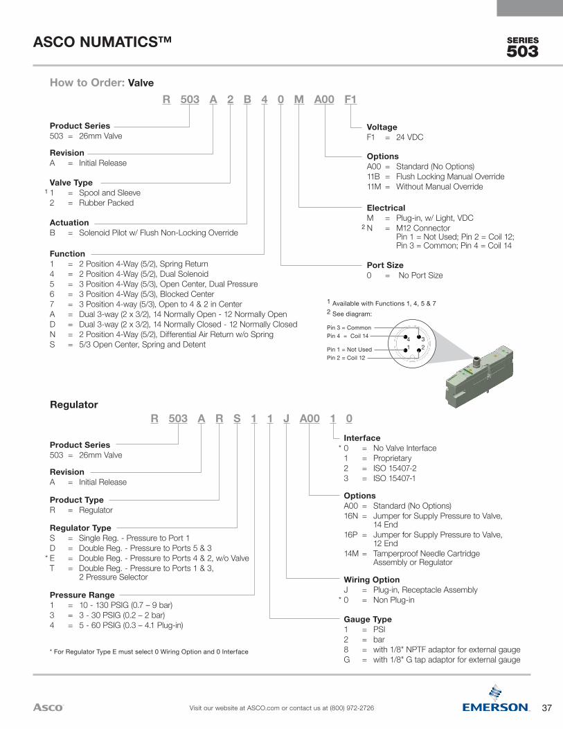
SERIES
503
Regulator
Gauge Type1 = PSI2 = bar8 = with 1/8" NPTF adaptor for external gaugeG = with 1/8" G tap adaptor for external gauge
*
Wiring OptionJ = Plug-in, Receptacle Assembly0 = Non Plug-in
OptionsA00 = Standard (No Options)16N = Jumper for Supply Pressure to Valve,
14 End16P = Jumper for Supply Pressure to Valve,
12 End14M = Tamperproof Needle Cartridge
Assembly or Regulator
*Interface0 = No Valve Interface 1 = Proprietary2 = ISO 15407-23 = ISO 15407-1
Pressure Range1 = 10 - 130 PSIG (0.7 – 9 bar)3 = 3 - 30 PSIG (0.2 – 2 bar)4 = 5 - 60 PSIG (0.3 – 4.1 Plug-in)
*
Regulator TypeS = Single Reg. - Pressure to Port 1D = Double Reg. - Pressure to Ports 5 & 3E = Double Reg. - Pressure to Ports 4 & 2, w/o ValveT = Double Reg. - Pressure to Ports 1 & 3,
2 Pressure Selector
Product TypeR = Regulator
RevisionA = Initial Release
Product Series503 = 26mm Valve
R 503 A R S 1 1 J A00 1 0
* For Regulator Type E must select 0 Wiring Option and 0 Interface
1 Available with Functions 1, 4, 5 & 72 See diagram:
4 321
Pin 3 = CommonPin 4 = Coil 14
Pin 1 = Not UsedPin 2 = Coil 12
Port Size0 = No Port Size
ElectricalM = Plug-in, w/ Light, VDCN = M12 Connector
Pin 1 = Not Used; Pin 2 = Coil 12; Pin 3 = Common; Pin 4 = Coil 14
OptionsA00 = Standard (No Options)11B = Flush Locking Manual Override11M = Without Manual Override
VoltageF1 = 24 VDC
Function1 = 2 Position 4-Way (5/2), Spring Return4 = 2 Position 4-Way (5/2), Dual Solenoid5 = 3 Position 4-Way (5/3), Open Center, Dual Pressure6 = 3 Position 4-Way (5/3), Blocked Center7 = 3 Position 4-way (5/3), Open to 4 & 2 in CenterA = Dual 3-way (2 x 3/2), 14 Normally Open - 12 Normally OpenD = Dual 3-way (2 x 3/2), 14 Normally Closed - 12 Normally ClosedN = 2 Position 4-Way (5/2), Differential Air Return w/o SpringS = 5/3 Open Center, Spring and Detent
ActuationB = Solenoid Pilot w/ Flush Non-Locking Override
1 Valve Type1 = Spool and Sleeve2 = Rubber Packed
RevisionA = Initial Release
Product Series503 = 26mm Valve
R 503 A 2 B 4 0 M A00 F1How to Order: Valve
2
37
ASCO NUMATICS™
Visit our website at ASCO.com or contact us at (800) 972-2726
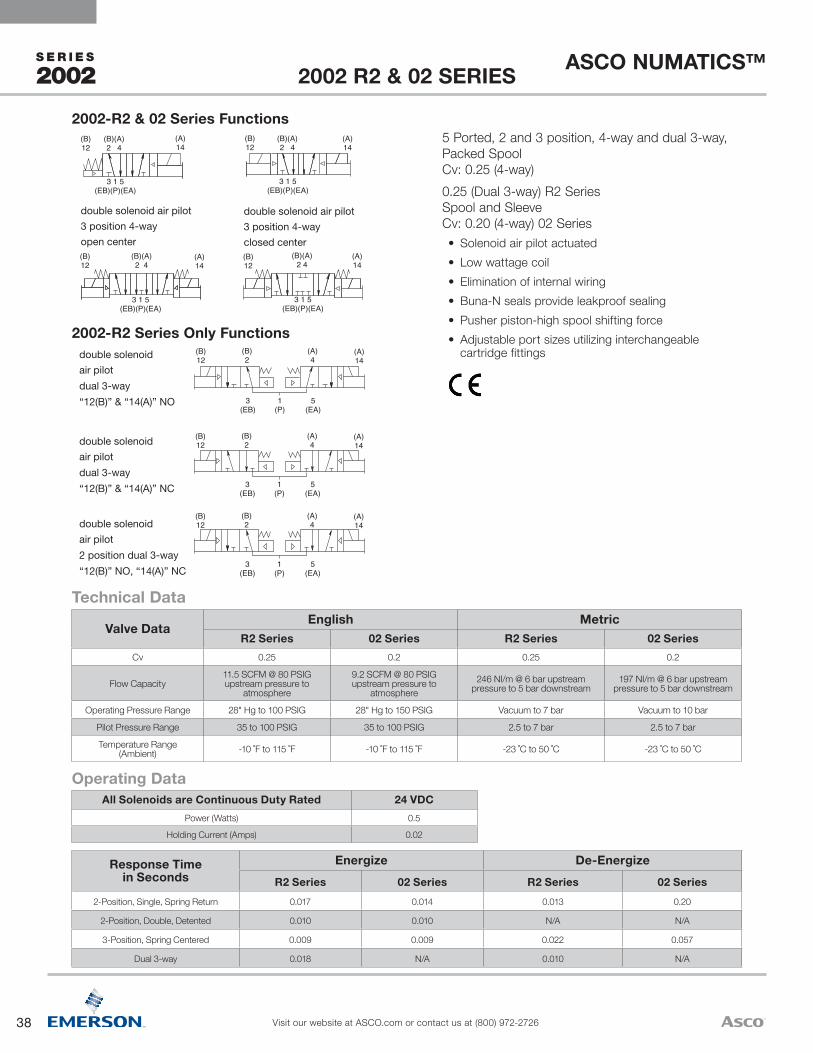
38
ASCO NUMATICS™
Visit our website at ASCO.com or contact us at (800) 972-2726
S E R I E S
2002
(B)12
(A)14
(B)2
(A)4
3(EB)
1(P)
5(EA)
(B)12
(A)14
(B)2
(A)4
3(EB)
1(P)
5(EA)
(B)12
(A)14
(B)2
(A)4
3(EB)
1(P)
5(EA)
double solenoidair pilot
dual 3-way
“12(B)” & “14(A)” NO
double solenoidair pilot
dual 3-way
“12(B)” & “14(A)” NC
double solenoidair pilot
2 position dual 3-way
“12(B)” NO, “14(A)” NC
double solenoid air pilot3 position 4-wayopen center
double solenoid air pilot3 position 4-wayclosed center
(B)12
(A)14
(B)(A)2 4
3 1 5(EB)(P)(EA)
(B)12
(A)14
(B)(A)2 4
3 1 5(EB)(P)(EA)
(B)12
(A)14
(B)(A)2 4
3 1 5(EB)(P)(EA)
(B)12
(A)14
(B)(A)2 4
3 1 5(EB)(P)(EA)
Response Timein Seconds
Energize De-EnergizeR2 Series 02 Series R2 Series 02 Series
2-Position, Single, Spring Return 0.017 0.014 0.013 0.20
2-Position, Double, Detented 0.010 0.010 N/A N/A
3-Position, Spring Centered 0.009 0.009 0.022 0.057
Dual 3-way 0.018 N/A 0.010 N/A
All Solenoids are Continuous Duty Rated 24 VDCPower (Watts) 0.5
Holding Current (Amps) 0.02
Operating Data
Valve DataEnglish Metric
R2 Series 02 Series R2 Series 02 SeriesCv 0.25 0.2 0.25 0.2
Flow Capacity11.5 SCFM @ 80 PSIG upstream pressure to
atmosphere
9.2 SCFM @ 80 PSIG upstream pressure to
atmosphere246 NI/m @ 6 bar upstream
pressure to 5 bar downstream197 NI/m @ 6 bar upstream
pressure to 5 bar downstream
Operating Pressure Range 28" Hg to 100 PSIG 28" Hg to 150 PSIG Vacuum to 7 bar Vacuum to 10 bar
Pilot Pressure Range 35 to 100 PSIG 35 to 100 PSIG 2.5 to 7 bar 2.5 to 7 bar
Temperature Range (Ambient) -10 ˚F to 115 ˚F -10 ˚F to 115 ˚F -23 ˚C to 50 ˚C -23 ˚C to 50 ˚C
Technical Data
5 Ported, 2 and 3 position, 4-way and dual 3-way, Packed Spool Cv: 0.25 (4-way)0.25 (Dual 3-way) R2 Series Spool and Sleeve Cv: 0.20 (4-way) 02 Series• Solenoid air pilot actuated• Low wattage coil• Elimination of internal wiring• Buna-N seals provide leakproof sealing• Pusher piston-high spool shifting force• Adjustable port sizes utilizing interchangeable
cartridge fittings2002-R2 Series Only Functions
2002-R2 & 02 Series Functions
2002 R2 & 02 SERIES

39
ASCO NUMATICS™
Visit our website at ASCO.com or contact us at (800) 972-2726
S E R I E S
2002
MountingZ3 = Manifold Block, Side Ports
Only, Single Solenoid OutputZ4 = Manifold Block, Side Ports
Only, Double Solenoid Output
Wiring OptionM = Plug-In DC, w/ Light0 = Blank Station
Port TypeK = Push-In FittingH = Barbed Fitting
Options11B = Flush Locking Manual Override14A = External Pilot Supply000 = No Option
Voltage61 = 24 VDC00 = Use w/ Blank Station Plate
Function4 = 2 Position 4-Way5 = 3 Position 4-Way, Open Center, Dual Pressure6 = 3 Position 4-Way, Closed CenterA = Dual 3-way, A Normally Open - B Normally OpenC = Dual 3-Way, A Normally Closed - B Normally OpenD = Dual 3-way, A Normally Closed - B Normally ClosedP = Blank Station Plate
Valve TypeBW = Solenoid Pilot w/ Flush Non-Locking Manual
Override & Differential Air ReturnBB = Double Solenoid Pilot w/ Flush Non-Locking
Manual Override00 = Blank Station
Port Size1 = 1/82 = 1/4D = 5/32 (4mm) (Port Type "K" Only)F = 6mm (Port Type "K" Only)
Series Identifier02 = Spool/Sleeve with Body
to Base PlugR2 = Rubber Packed Spool
with Body to Base Plug
R2 1 BB A Z4 M K 000 61How To Order: Valves

40
ASCO NUMATICS™
Visit our website at ASCO.com or contact us at (800) 972-2726
S E R I E S
2005
single solenoid air pilot2 position 4-way
double solenoid air pilot2 position 4-way
double solenoid air pilot3 position 4-wayopen center
double solenoid air pilot3 position 4-wayclosed center
1214 24
315
1214 24
315
1214 24
315
1214 24
315
1214 24
3 1 5
double solenoid air pilot3 position 4-way pressure center
(B)12
(A)14
(B)2
(A)4
3(EB)
1(P)
5(EA)
(B)12
(A)14
(B)2
(A)4
3(EB)
1(P)
5(EA)
(B)12
(A)14
(B)2
(A)4
3(EB)
1(P)
5(EA)
double solenoid2 position dual 3-way“14(A)” & “12(B)” NO
double solenoid2 position dual 3-way“14(A)” & “12(B)” NC
double solenoid2 position dual 3-way
NO“12(B)”, NC“14(A)”
Response Timein Seconds Energize De-Energize
2-Position, Single, Spring Return 0.014 0.016
2-Position, Double, Detented 0.013 N/A
3-Position, Spring Centered 0.014 0.016
Dual 3-way 0.014 0.016
All Solenoids are Continuous Duty Rated 24 VDCPower (Watts) 1.35
Holding Current (Amps) 0.056
Operating Data
Valve Data English MetricCv 0.56 0.56
Flow Capacity 26 SCFM @ 80 PSIG upstream pressure to atmosphere 552 NI/m @ 6 bar upstream to 5 bar downstream
Operating Pressure Range 28" Hg Vacuum to 150 PSIG Vacuum to 10 bar
Operating Pressure Range – 3 Way 22" Hg Vacuum to 100 PSIG Vacuum to 7 bar
Pilot Pressure Range 26 to 120 PSIG 1.8 to 8.2 bar
Pilot Pressure Range – 3 Way 26 to 100 PSIG 1.8 to 7 bar
Pilot Pressure Vacuum 50 to 100 PSIG 3.5 to 7 bar
Temperature Range (Ambient) -10 ˚F to 115 ˚F -23 ˚C to 50 ˚C
Technical Data
5 Ported, 2 and 3 position, 4-way, Spool & Sleeve Cv: 0.56Dual 3-Way Pack Spool Cv: 0.56• Solenoid air pilot actuated• Low wattage coil• DC solenoids polarity insensitive with spike
suppression• Plug together circuit boards eliminate internal wiring• Integral recessed gaskets• Interchangeable Push-In fittings to accommodate
various tube sizes• Simple conversion from internal to external pilot
supply• NEMA 4/IP65
2005 SERIES

41
ASCO NUMATICS™
Visit our website at ASCO.com or contact us at (800) 972-2726
S E R I E S
2005
NOTE: Regulator Gauges must be offset on alternating stations to prevent interference (see photo) Odd numbered stations will use either standard (no option) or top facing (“16W” option) gauges
Even numbered stations will use either extended standard (“61Y” option) or extended top facing (“63D” option) gauges
Wiring OptionJ = Plug-In Receptacle Assembly
Port TypeK = Push-InP = NPTF (1/8 Only)Q = G Tap (1/8 Only)
See NOTE Below
Options12H = Less Gauge16N = Jumper on 14 (A) End16P = Jumper on 12 (B) End16W = Top Facing Gauge61Y = Extended Gauge63D = 16W + 61Y Extended
Top Facing Gauge000 = No Option
MountingZ0 = Manifold Block w/ Side and Bottom Ports, Transfer board, used w/ RE RegulatorsZ1 = Manifold Block w/ Side and Bottom Ports, Single Solenoid Internal Circuit BoardZ2 = Manifold Block w/ Side and Bottom Ports, Double Solenoid Internal Circuit BoardZ5 = Z1 w/ Speed ControlZ6 = Z2 w/ Speed ControlR1 = Z1 w/ Ribbon Cable ConnectorR2 = Z2 w/ Ribbon Cable ConnectorR5 = Z5 w/ Ribbon Cable ConnectorR6 = Z6 w/ Ribbon Cable Connector
Pressure Range1 = 10 – 130 PSIG (0.7 – 9 bar) 3 = 3 – 30 PSIG (0.2 – 2 bar) 4 = 5 – 60 PSIG (0.5 – 4 bar)
Regulator TypeRS = Single Pressure to Port 1 (P)RD = Dual Pressure to Ports 3 (EB) & 5 (EA)RE = Dual Pressure to Ports 4 (4) & 2 (B)RT = 2 Pressure Selector* For Metric Gauge replace R with E in 4th digit
Valve Series & Port Size051 = 1/8052 = 1/4 (Push-In Only)05F = 6mm05H = 8mm* Use for Regulator Unit Only (Mounting = 00)
051 RS 1 Z1 J K 000 00Regulators
MountingZ1 = Manifold Block w/ Side and Bottom Ports,
Single Solenoid Internal Circuit BoardZ2 = Manifold Block w/ Side and Bottom Ports,
Double Solenoid Internal Circuit BoardZ5 = Z1 w/ Speed ControlZ6 = Z2 w/ Speed ControlR1 = Z1 w/ Ribbon Cable ConnectorR2 = Z2 w/ Ribbon Cable ConnectorR5 = Z5 w/ Ribbon Cable ConnectorR6 = Z6 w/ Ribbon Cable Connector
Wiring OptionM = Plug-In DC, w/ Light0 = Blank Station
Port TypeL = Push-In FittingN = NPTF (1/8 Only)G = G Tap (1/8 Only)
Options11B = Flush Locking Manual Override11M = No Override000 = No Option
Voltage61 = 24 VDC00 = Use w/ Blank Station Plate
Function4 = 2 Position 4-Way5 = 3 Position 4-Way, Open Center6 = 3 Position 4-Way, Closed Center7 = 3 Position, 4-Way Pressure CenterA = Dual 3-Way, A Normally Open - B Normally OpenB = Dual 3-Way, Vacuum Service, A Normally Open -
B Normally OpenD = Dual 3-way, A Normally Closed - B Normally ClosedE = Dual 3-Way, Vacuum Service, A Normally Closed -
B Normally ClosedP = Blank Station Plate
Valve TypeBA = Single Solenoid Pilot (Spring Return) w/
Flush Non-Locking OverrideBB = Double Solenoid Pilot w/ Flush Non-Locking
Override00 = Blank Station
Valve Series & Port Size051 = 1/8 (Threaded Only)052 = 1/4 (Push-In Only)05F = 6mm05H = 8mm
051 BB 4 Z6 M N 000 61How to Order: Valves
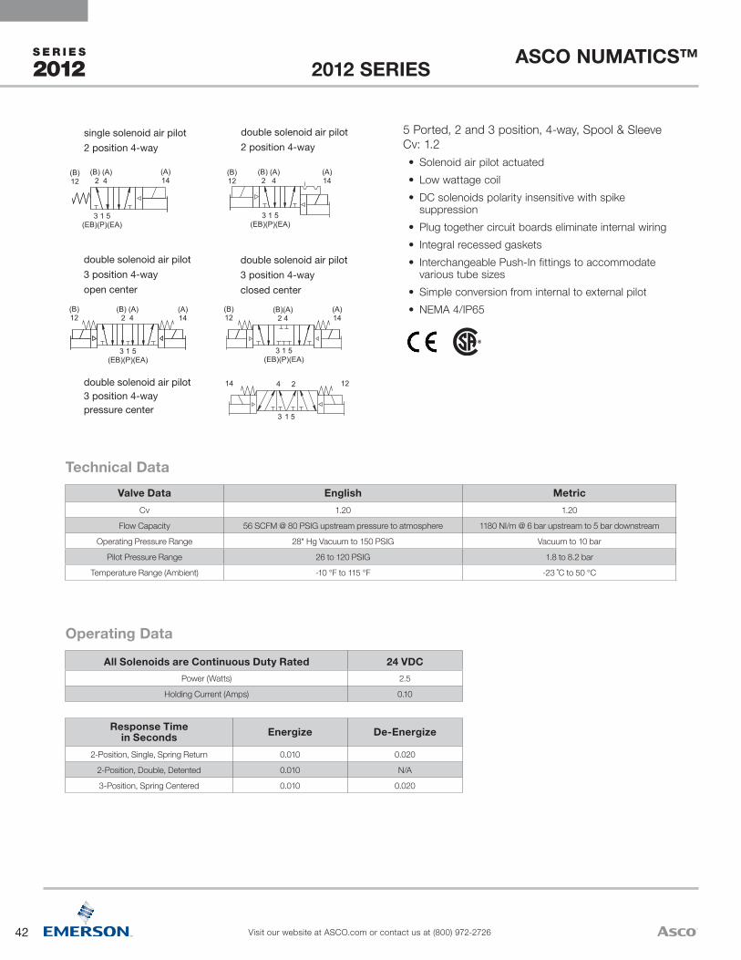
42
ASCO NUMATICS™
Visit our website at ASCO.com or contact us at (800) 972-2726
S E R I E S
2012
(A ) 14
(B ) 12
3 1 5 (EB)(P)(EA)
(B) (A ) 2 4
(A ) 14
(B ) 12
3 1 5 (EB)(P)(EA)
(B) (A ) 2 4
(A ) 14
(B ) 12
3 1 5 (EB)(P)(EA)
(B) (A ) 2 4
(A ) 14
(B ) 12
3 1 5 (EB)(P)(EA)
(B)(A ) 2 4
single solenoid air pilot2 position 4-way
double solenoid air pilot2 position 4-way
double solenoid air pilot
double solenoid air pilot3 position 4-way pressure center
3 position 4-wayopen center
double solenoid air pilot3 position 4-wayclosed center
1214 24
3 1 5
Response Timein Seconds Energize De-Energize
2-Position, Single, Spring Return 0.010 0.020
2-Position, Double, Detented 0.010 N/A
3-Position, Spring Centered 0.010 0.020
All Solenoids are Continuous Duty Rated 24 VDCPower (Watts) 2.5
Holding Current (Amps) 0.10
Operating Data
Valve Data English MetricCv 1.20 1.20
Flow Capacity 56 SCFM @ 80 PSIG upstream pressure to atmosphere 1180 NI/m @ 6 bar upstream to 5 bar downstream
Operating Pressure Range 28" Hg Vacuum to 150 PSIG Vacuum to 10 bar
Pilot Pressure Range 26 to 120 PSIG 1.8 to 8.2 bar
Temperature Range (Ambient) -10 °F to 115 °F -23 ˚C to 50 °C
Technical Data
5 Ported, 2 and 3 position, 4-way, Spool & Sleeve Cv: 1.2• Solenoid air pilot actuated• Low wattage coil• DC solenoids polarity insensitive with spike
suppression• Plug together circuit boards eliminate internal wiring• Integral recessed gaskets• Interchangeable Push-In fittings to accommodate
various tube sizes• Simple conversion from internal to external pilot• NEMA 4/IP65
2012 SERIES
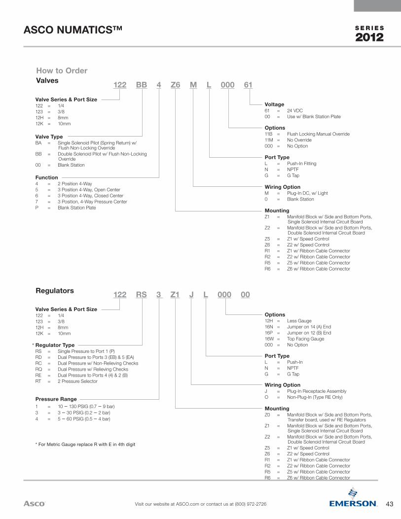
43
ASCO NUMATICS™
Visit our website at ASCO.com or contact us at (800) 972-2726
S E R I E S
2012
MountingZ0 = Manifold Block w/ Side and Bottom Ports,
Transfer board, used w/ RE RegulatorsZ1 = Manifold Block w/ Side and Bottom Ports,
Single Solenoid Internal Circuit BoardZ2 = Manifold Block w/ Side and Bottom Ports,
Double Solenoid Internal Circuit BoardZ5 = Z1 w/ Speed ControlZ6 = Z2 w/ Speed ControlR1 = Z1 w/ Ribbon Cable ConnectorR2 = Z2 w/ Ribbon Cable ConnectorR5 = Z5 w/ Ribbon Cable ConnectorR6 = Z6 w/ Ribbon Cable Connector
Wiring OptionJ = Plug-In Receptacle AssemblyO = Non-Plug-In (Type RE Only)
Port TypeL = Push-InN = NPTFG = G Tap
Options12H = Less Gauge16N = Jumper on 14 (A) End16P = Jumper on 12 (B) End16W = Top Facing Gauge000 = No Option
Pressure Range1 = 10 – 130 PSIG (0.7 – 9 bar) 3 = 3 – 30 PSIG (0.2 – 2 bar) 4 = 5 – 60 PSIG (0.5 – 4 bar)
Regulator TypeRS = Single Pressure to Port 1 (P)RD = Dual Pressure to Ports 3 (EB) & 5 (EA)RC = Dual Pressure w/ Non-Relieving ChecksRQ = Dual Pressure w/ Relieving ChecksRE = Dual Pressure to Ports 4 (4) & 2 (B)RT = 2 Pressure Selector
Valve Series & Port Size122 = 1/4123 = 3/812H = 8mm12K = 10mm
122 RS 3 Z1 J L 000 00Regulators
MountingZ1 = Manifold Block w/ Side and Bottom Ports,
Single Solenoid Internal Circuit BoardZ2 = Manifold Block w/ Side and Bottom Ports,
Double Solenoid Internal Circuit BoardZ5 = Z1 w/ Speed ControlZ6 = Z2 w/ Speed ControlR1 = Z1 w/ Ribbon Cable ConnectorR2 = Z2 w/ Ribbon Cable ConnectorR5 = Z5 w/ Ribbon Cable ConnectorR6 = Z6 w/ Ribbon Cable Connector
Wiring OptionM = Plug-In DC, w/ Light0 = Blank Station
Port TypeL = Push-In FittingN = NPTFG = G Tap
Options11B = Flush Locking Manual Override11M = No Override000 = No Option
Voltage61 = 24 VDC00 = Use w/ Blank Station Plate
Function4 = 2 Position 4-Way5 = 3 Position 4-Way, Open Center6 = 3 Position 4-Way, Closed Center7 = 3 Position, 4-Way Pressure CenterP = Blank Station Plate
Valve TypeBA = Single Solenoid Pilot (Spring Return) w/
Flush Non-Locking OverrideBB = Double Solenoid Pilot w/ Flush Non-Locking
Override00 = Blank Station
Valve Series & Port Size122 = 1/4123 = 3/812H = 8mm12K = 10mm
122 BB 4 Z6 M L 000 61
How to OrderValves
*
* For Metric Gauge replace R with E in 4th digit
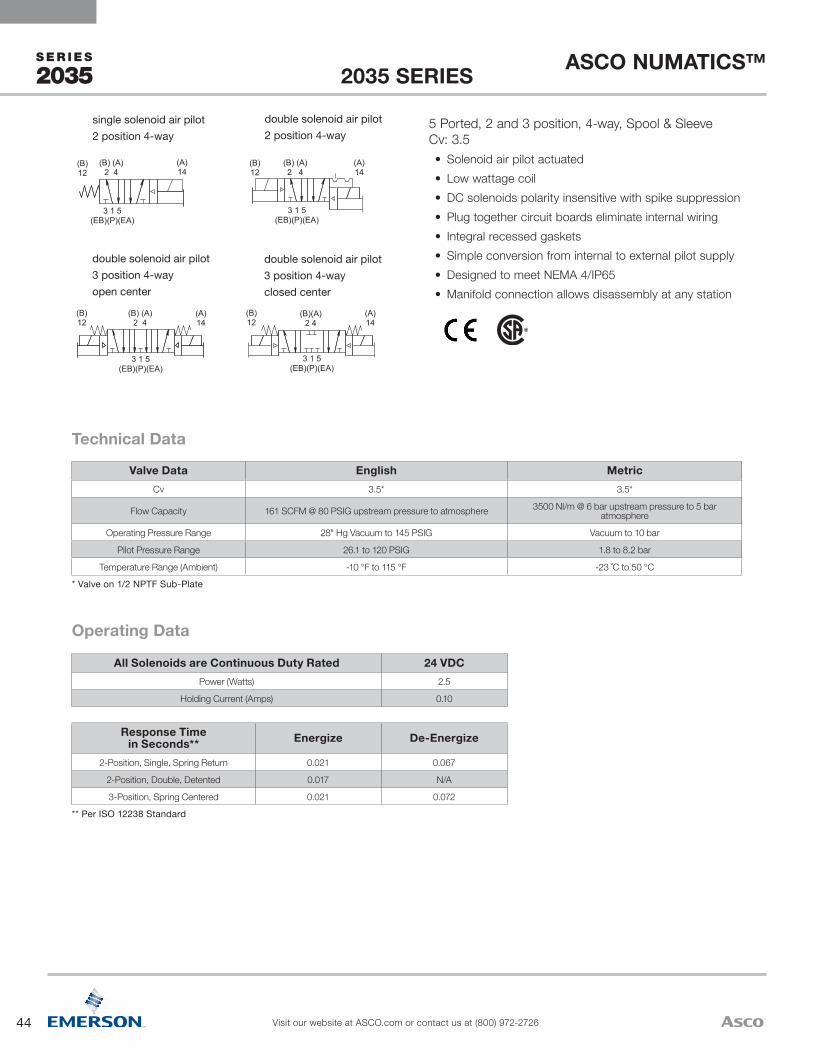
44
ASCO NUMATICS™
Visit our website at ASCO.com or contact us at (800) 972-2726
S E R I E S
2035
(A ) 14
(B ) 12
3 1 5 (EB)(P)(EA)
(B) (A ) 2 4
(A ) 14
(B ) 12
3 1 5 (EB)(P)(EA)
(B) (A ) 2 4
(A ) 14
(B ) 12
3 1 5 (EB)(P)(EA)
(B) (A ) 2 4
(A ) 14
(B ) 12
3 1 5 (EB)(P)(EA)
(B)(A ) 2 4
single solenoid air pilot2 position 4-way
double solenoid air pilot2 position 4-way
double solenoid air pilot3 position 4-wayopen center
double solenoid air pilot3 position 4-wayclosed center
Response Timein Seconds** Energize De-Energize
2-Position, Single, Spring Return 0.021 0.067
2-Position, Double, Detented 0.017 N/A
3-Position, Spring Centered 0.021 0.072
** Per ISO 12238 Standard
All Solenoids are Continuous Duty Rated 24 VDCPower (Watts) 2.5
Holding Current (Amps) 0.10
Operating Data
Valve Data English MetricCv 3.5* 3.5*
Flow Capacity 161 SCFM @ 80 PSIG upstream pressure to atmosphere 3500 Nl/m @ 6 bar upstream pressure to 5 bar atmosphere
Operating Pressure Range 28" Hg Vacuum to 145 PSIG Vacuum to 10 bar
Pilot Pressure Range 26.1 to 120 PSIG 1.8 to 8.2 bar
Temperature Range (Ambient) -10 °F to 115 °F -23 ˚C to 50 °C* Valve on 1/2 NPTF Sub-Plate
Technical Data
5 Ported, 2 and 3 position, 4-way, Spool & Sleeve Cv: 3.5• Solenoid air pilot actuated• Low wattage coil• DC solenoids polarity insensitive with spike suppression• Plug together circuit boards eliminate internal wiring• Integral recessed gaskets• Simple conversion from internal to external pilot supply• Designed to meet NEMA 4/IP65• Manifold connection allows disassembly at any station
2035 SERIES

45
ASCO NUMATICS™
Visit our website at ASCO.com or contact us at (800) 972-2726
S E R I E S
2035
MountingZ0 = Manifold Block w/ Side and Bottom Ports,
Transfer board, used w/ RE RegulatorsZ1 = Manifold Block w/ Side and Bottom Ports,
Single Solenoid Internal Circuit BoardZ2 = Manifold Block w/ Side and Bottom Ports,
Double Solenoid Internal Circuit BoardZ5 = Z1 w/ Speed ControlZ6 = Z2 w/ Speed ControlR1 = Z1 w/ Ribbon Cable ConnectorR2 = Z2 w/ Ribbon Cable ConnectorR5 = Z5 w/ Rib on Cable ConnectorR6 = Z6 w /Ribbon Cable Connector
Wiring OptionJ = Plug-In Receptacle AssemblyO = Non-Plug-In (Type RE Only)
Port TypeN = NPTFG = G Tap
Options12H = Less Gauge16N = Jumper on 14 (A) End16P = Jumper on 12 (B) End16W = Top Facing Gauge000 = No Option
Pressure Range1 = 10 – 130 PSIG (0.7 – 9 bar) 3 = 3 – 30 PSIG (0.2 – 2 bar) 4 = 5 – 60 PSIG (0.5 – 4 bar)
Regulator TypeRS = Single Pressure to Port 1 (P)RD = Dual Pressure to Ports 3 (EB) & 5 (EA)RC = Dual Pressure w/ Non-Relieving ChecksRQ = Dual Pressure w/ Relieving ChecksRE = Dual Pressure to Ports 4 (4) & 2 (B)RT = 2 Pressure Selector* For Metric Gauge replace R with E in 4th digit
Valve Series & Port Size353 = 3/8354 = 1/2
353 RS 3 Z1 J N 000 00Regulators
MountingZ1 = Manifold Block w/ Side and Bottom Ports,
Single Solenoid Internal Circuit BoardZ2 = Manifold Block w/ Side and Bottom Ports,
Double Solenoid Internal Circuit BoardZ5 = Z1 w/ Speed ControlZ6 = Z2 w/ Speed ControlR1 = Z1 w/ Ribbon Cable ConnectorR2 = Z2 w/ Ribbon Cable ConnectorR5 = Z5 w/ Ribbon Cable ConnectorR6 = Z6 w/ Ribbon Cable Connector
Wiring OptionM = Plug-In DC, w/ Light0 = Blank Station
Port TypeN = NPTFG = G Tap
Options11B = Flush Locking Manual Override11M = No Override000 = No Option
Voltage61 = 24 VDC00 = Use w/ Blank Station Plate
Function4 = 2 Position 4-Way5 = 3 Position 4-Way, Open Center6 = 3 Position 4-Way, Closed CenterP = Blank Station Plate
Valve TypeBA = Single Solenoid Pilot (Spring Return) w/
Flush Non-Locking OverrideBB = Double Solenoid Pilot w/ Flush Non-Locking
Override00 = Blank Station
Valve Series & Port Size353 = 3/8354 = 1/2
353 BB 4 Z6 M N 000 61How to Order: Valves
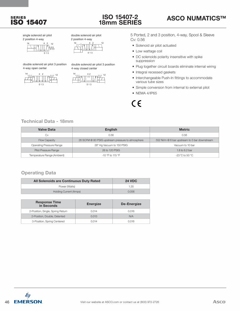
46
ASCO NUMATICS™
Visit our website at ASCO.com or contact us at (800) 972-2726
SERIES
ISO 15407
1214
5 1 3
5 1 3 5 1 3
5 1 3
4 2
1214 4 2 1214 4 2
1214 4 2
single solenoid air pilot2 position 4-way
double solenoid air pilot2 position 4-way
double solenoid air pilot 3 position 4-way open center
double solenoid air pilot 3 position 4-way closed center
Response Timein Seconds Energize De-Energize
2-Position, Single, Spring Return 0.014 0.016
2-Position, Double, Detented 0.013 N/A
3-Position, Spring Centered 0.014 0.016
All Solenoids are Continuous Duty Rated 24 VDCPower (Watts) 1.35
Holding Current (Amps) 0.056
Operating Data
Valve Data English MetricCv 0.56 0.56
Flow Capacity 26 SCFM @ 80 PSIG upstream pressure to atmosphere 552 NI/m @ 6 bar upstream to 5 bar downstream
Operating Pressure Range 28" Hg Vacuum to 150 PSIG Vacuum to 10 bar
Pilot Pressure Range 26 to 120 PSIG 1.8 to 8.2 bar
Temperature Range (Ambient) -10 °F to 115 °F -23 ˚C to 50 °C
Technical Data - 18mm
5 Ported, 2 and 3 position, 4-way, Spool & Sleeve Cv: 0.56• Solenoid air pilot actuated• Low wattage coil • DC solenoids polarity insensitive with spike
suppression• Plug together circuit boards eliminate internal wiring• Integral recessed gaskets• Interchangeable Push-In fittings to accommodate
various tube sizes• Simple conversion from internal to external pilot• NEMA 4/IP65
ISO 15407-2 18mm SERIES
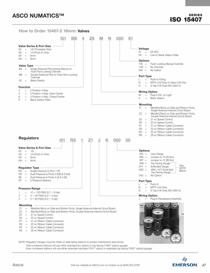
47
ASCO NUMATICS™
Visit our website at ASCO.com or contact us at (800) 972-2726
SERIES
ISO 15407 .
NOTE: Regulator Gauges must be offset on alternating stations to prevent interference (see photo) Odd numbered stations will use either standard (no option) or top facing (“16W” option) gauges
Even numbered stations will use either extended standard (“61Y” opton) or extended top facing (“63D” option) gauges
Wiring OptionJ = Plug-In Receptacle Assembly
Port TypeL = Push-InN = NPTF (1/8 Only)G = G Tap (1/8 Only) ISO 228/I-G
See NOTE Below
Options12H = Less Gauge16N = Jumper on 14 (A) End16P = Jumper on 12 (B) End16W = Top Facing Gauge61Y = Extended Gauge63D = 16W + 61Y Extended
Top Facing Gauge000 = No Option
MountingZ1 = Manifold Block w/ Side and Bottom Ports, Single Solenoid Internal Circuit BoardZ2 = Manifold Block w/ Side and Bottom Ports, Double Solenoid Internal Circuit BoardZ5 = Z1 w/ Speed ControlZ6 = Z2 w/ Speed ControlR1 = Z1 w/ Ribbon Cable ConnectorR2 = Z2 w/ Ribbon Cable ConnectorR5 = Z5 w/ Ribbon Cable ConnectorR6 = Z6 w/ Ribbon Cable Connector
Pressure Range1 = 10 – 130 PSIG (0.7 – 9 bar) 3 = 3 – 30 PSIG (0.2 – 2 bar) 4 = 5 – 60 PSIG (0.5 – 4 bar)
Regulator TypeRS = Single Pressure to Port 1 (P)RD = Dual Pressure to Ports 3 (EB) & 5 (EA)RE = Dual Pressure to Ports 4 (4) & 2 (B)RT = 2 Pressure Selector
Valve Series & Port SizeI51 = 1/8I52 = 1/4 (Push-In Only)I5F = 6mmI5H = 8mm
I51 RS 1 Z1 J K 000 00Regulators
MountingZ1 = Manifold Block w/ Side and Bottom Ports,
Single Solenoid Internal Circuit BoardZ2 = Manifold Block w/ Side and Bottom Ports,
Double Solenoid Internal Circuit BoardZ5 = Z1 w/ Speed ControlZ6 = Z2 w/ Speed ControlR1 = Z1 w/ Ribbon Cable ConnectorR2 = Z2 w/ Ribbon Cable ConnectorR5 = Z5 w/ Ribbon Cable ConnectorR6 = Z6 w/ Ribbon Cable Connector
Wiring OptionM = Plug-In DC, w/ Light0 = Blank Station
Port TypeL = Push-In FittingN = NPTF (1/8 Only) or Valve Unit OnlyG = G Tap (1/8 Only) ISO 228/I-G
Options11B = Flush Locking Manual Override11M = No Override000 = No Option
Voltage61 = 24 VDC00 = Use w/ Blank Station Plate
Function4 = 2 Position 4-Way5 = 3 Position 4-Way, Open Center6 = 3 Position 4-Way, Closed CenterP = Blank Station Plate
Valve TypeBA = Single Solenoid Pilot (Spring Return) w/
Flush Non-Locking OverrideBB = Double Solenoid Pilot w/ Flush Non-Locking
Override00 = Blank Station
Valve Series & Port SizeI51 = 1/8 (Threaded Only)I52 = 1/4 (Push-In Only)I5F = 6mmI5H = 8mm
I51 BB 4 Z6 M N 000 61
How to Order 15407-2 18mm: Valves

48
ASCO NUMATICS™
Visit our website at ASCO.com or contact us at (800) 972-2726
SERIES
ISO 15407
1214
5 1 3
5 1 3 5 1 3
5 1 3
4 2
1214 4 2 1214 4 2
1214 4 2
single solenoid air pilot2 position 4-way
double solenoid air pilot2 position 4-way
double solenoid air pilot 3 position 4-way open center
double solenoid air pilot 3 position 4-way closed center
Response Timein Seconds Energize De-Energize
2-Position, Single, Spring Return 0.010 0.020
2-Position, Double, Detented 0.010 N/A
3-Position, Spring Centered 0.010 0.020
All Solenoids are Continuous Duty Rated 24 VDCPower (Watts) 2.5
Holding Current (Amps) 0.10
Operating Data
Valve Data English MetricCv 1.20 1.20
Flow Capacity 56 SCFM @ 80 PSIG upstream pressure to atmosphere 1180 NI/m @ 6 bar upstream to 5 bar downstream
Operating Pressure Range 28" Hg Vacuum to 150 PSIG Vacuum to 10 bar
Pilot Pressure Range 26 to 120 PSIG 1.8 to 8.2 bar
Temperature Range (Ambient) -10 °F to 115 °F -23 ˚C to 50 °C
Technical Data - 26mm
5 Ported, 2 and 3 position, 4-way, Spool & Sleeve Cv: 1.2• Solenoid air pilot actuated• Low wattage coil• DC solenoids polarity insensitive with spike suppression• Plug together circuit boards eliminate internal wiring• Integral recessed gaskets• Interchangeable Push-In fittings to accommodate various
tube sizes• Simple conversion from internal to external pilot• Modular plug-together Fieldbus electronics• NEMA 4/IP65
ISO 15407-2 26mm SERIES
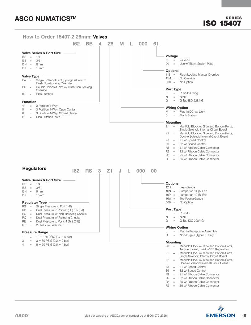
49
ASCO NUMATICS™
Visit our website at ASCO.com or contact us at (800) 972-2726
SERIES
ISO 15407 .
MountingZ0 = Manifold Block w/ Side and Bottom Ports,
Transfer board, used w/ RE RegulatorsZ1 = Manifold Block w/ Side and Bottom Ports,
Single Solenoid Internal Circuit BoardZ2 = Manifold Block w/ Side and Bottom Ports,
Double Solenoid Internal Circuit BoardZ5 = Z1 w/ Speed ControlZ6 = Z2 w/ Speed ControlR1 = Z1 w/ Ribbon Cable ConnectorR2 = Z2 w/ Ribbon Cable ConnectorR5 = Z5 w/ Ribbon Cable ConnectorR6 = Z6 w/ Ribbon Cable Connector
Wiring OptionJ = Plug-In Receptacle AssemblyO = Non-Plug-In (Type RE Only)
Port TypeL = Push-InN = NPTFG = G Tap IOO 228/I-G
Options12H = Less Gauge16N = Jumper on 14 (A) End16P = Jumper on 12 (B) End16W = Top Facing Gauge000 = No Option
Pressure Range1 = 10 – 130 PSIG (0.7 – 9 bar) 3 = 3 – 30 PSIG (0.2 – 2 bar) 4 = 5 – 60 PSIG (0.5 – 4 bar)
Regulator TypeRS = Single Pressure to Port 1 (P)RD = Dual Pressure to Ports 3 (EB) & 5 (EA)RC = Dual Pressure w/ Non-Relieving ChecksRQ = Dual Pressure w/ Relieving ChecksRE = Dual Pressure to Ports 4 (4) & 2 (B)RT = 2 Pressure Selector
Valve Series & Port SizeI62 = 1/4I63 = 3/8I6H = 8mmI6K = 10mm
I62 RS 3 Z1 J L 000 00Regulators
MountingZ1 = Manifold Block w/ Side and Bottom Ports,
Single Solenoid Internal Circuit BoardZ2 = Manifold Block w/ Side and Bottom Ports,
Double Solenoid Internal Circuit BoardZ5 = Z1 w/ Speed ControlZ6 = Z2 w/ Speed ControlR1 = Z1 w/ Ribbon Cable ConnectorR2 = Z2 w/ Ribbon Cable ConnectorR5 = Z5 w/ Ribbon Cable ConnectorR6 = Z6 w/ Ribbon Cable Connector
Wiring OptionM = Plug-In DC, w/ Light0 = Blank Station
Port TypeL = Push-In FittingN = NPTFG = G Tap ISO 228/I-G
Options11B = Flush Locking Manual Override11M = No Override000 = No Option
Voltage61 = 24 VDC00 = Use w/ Blank Station Plate
Function4 = 2 Position 4-Way5 = 3 Position 4-Way, Open Center6 = 3 Position 4-Way, Closed CenterP = Blank Station Plate
Valve TypeBA = Single Solenoid Pilot (Spring Return) w/
Flush Non-Locking OverrideBB = Double Solenoid Pilot w/ Flush Non-Locking
Override00 = Blank Station
Valve Series & Port SizeI62 = 1/4I63 = 3/8I6H = 8mmI6K = 10mm
I62 BB 4 Z6 M L 000 61How to Order 15407-2 26mm: Valves

50
ASCO NUMATICS™
Visit our website at ASCO.com or contact us at (800) 972-2726
SERIES
ISO 5599
Response Time in Seconds
Direct Acting Solenoid Pilot ActuatedEnergize (Sec) De-Energize (Sec) Energize (Sec) De-Energize (Sec)
Sizes 1 & 2 Size 3 Sizes 1 & 2 Size 3 Size 1 Size 2 Size 3 Size 1 Size 2 Size 32-Position, Single, Spring Return 0.038 NA 0.012 NA 0.013 0.013 0.020 0.036 0.060 0.066
2-Position, Double, Detented 0.012 NA NA NA 0.013 0.013 0.020 NA NA NA
3-Position, Spring Centered 0.038 NA NA NA 0.013 0.013 0.020 0.036 0.060 0.066
All Solenoids are Continuous Duty Rated
24 VDC Direct Acting 24 VDC Solenoid PilotSizes 1 & 2 Size 3 Size 1 & 2 Size 3
Power (Watts) - All Sizes 6.0 NA 4.0 4.0
Holding Current (Amps) .25 NA 0.016 0.016
In-Rush Current (Amps) - All Sizes NA NA NA NA
Operating Data - All solenoids continuous duty rated
Valve DataDirect Acting Solenoid Pilot Actuated
English Metric English Metric
CvSize 1Size 2Size 3
1.22
NA
1.22
NA
1.32.95.3
1.32.95.3
Flow CapacitySize 1Size 2Size 3
55.5 SCFM101.7 SCFM
NA
1181 NI/m2168 NI/m
NA
60.1 SCFM134.0 SCFM245.0 SCFM
1280 NI/m2857 NI/m5222 NI/m
Main valve operating pressure range - All sizes
80 PSIG upstreampressure to atmosphere
6 bar upstreamto 5 bar downstream
80 PSIG upstreampressure to atmosphere
6 bar upstreamto 5 bar downstream
Pilot pressure range - All sizes 28" Hg to 232 PSIG Vacuum to 16 bar 15 to 125 PSIG 1 to 8.6 bar
Temperature Range (Ambient) - All sizes -10 ˚F to 115 ˚F -23 ˚C to 50 ˚C -10 ˚F to 115 ˚F -23 ˚C to 50 ˚C
Technical Data
5 Ported, 4-way, 2 and 3 position, Spool & Sleeve, Cv: 1.2 to 5.3• Direct and Solenoid Pilot Actuated• Complies with ISO Standard 5599/2- Sizes 1, 2 & 3• NEMA 4/IP65
B A
PEB EA
B A
double solenoid 3 Position 4-Way (5/3), open to 4 (A) and 2 (B) in center
single solenoid2 position 4-way
double solenoid2 position 4-way
double solenoid3 position 4-way open center
double solenoid3 position 4-way closed center
double solenoid pilot 3 Position 4-Way (5/3), open to 4 (A) and 2 (B) in center
4 2
5 1 3
14 12
double solenoid pilot 3 Position 4-Way (5/3), open to 4 (A) and 2 (B) in center
4 2
5 1 3
14 12
Solenoid Pilot Actuated
B A
PEB EA
B A
double solenoid 3 Position 4-Way (5/3), open to 4 (A) and 2 (B) in center
double solenoid 3 position 4-way closed center
double solenoid 3 position 4-way open center
double solenoid 2 position 4-way
single solenoid 2 position 4-way
Direct Solenoid Actuated
ISO 5599/2 SERIES
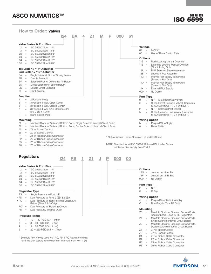
51
ASCO NUMATICS™
Visit our website at ASCO.com or contact us at (800) 972-2726
SERIES
ISO 5599
* Solenoid Pilot Valves used with RC, RD & RQ Regulators must have the pilot supply from other than internally from Port 1 (P)
MountingZ0 = Manifold Block w/ Side and Bottom Ports,
Transfer board, used w/ RE RegulatorsZ1 = Manifold Block w/ Side and Bottom Ports,
Single Solenoid Internal Circuit BoardZ2 = Manifold Block w/ Side and Bottom Ports,
Double Solenoid Internal Circuit BoardZ5 = Z1 w/ Speed ControlZ6 = Z2 w/ Speed ControlR1 = Z1 w/ Ribbon Cable ConnectorR2 = Z2 w/ Ribbon Cable ConnectorR5 = Z5 w/ Ribbon Cable ConnectorR6 = Z6 w/ Ribbon Cable Connector
Wiring OptionJ = Plug-In Receptacle AssemblyO = Non-Plug-In (Type RE Only)
Port TypeP = NPTFQ = G Tap
Options16N = Jumper on 14 (A) End16P = Jumper on 12 (B) End000 = No Option
Pressure Range1 = 10 – 130 PSIG (0.7 – 9 bar) 3 = 3 – 30 PSIG (0.2 – 2 bar) 4 = 5 – 60 PSIG (0.5 – 4 bar) 6 = 20 – 250 PSIG (1.4 – 17 bar)
Regulator TypeRS = Single Pressure to Port 1 (P)RD = Dual Pressure to Ports 3 (EB) & 5 (EA)RC = Dual Pressure w/ Non-Relieving Checks Air
Return (Sizes 2 & 3 Only)RQ* = Dual Pressure w/ Relieving ChecksRE = Dual Pressure, External Outlet
Valve Series & Port SizeI12 = ISO 5599/2 Size 1 1/4"I13 = ISO 5599/2 Size 1 3/8"I23 = ISO 5599/2 Size 2 3/8"I24 = ISO 5599/2 Size 2 1/2"I34 = ISO 5599/2 Size 3 1/2"I35 = ISO 5599/2 Size 3 3/4"
I24 RS 1 Z1 J P 000 00Regulators
* Not available in Direct Operated SA and SS Series
NOTE: Standard for all ISO 5599/2 Solenoid Pilot Valve Series is internal pilot supply from Port 1
MountingZ1 = Manifold Block w/ Side and Bottom Ports, Single Solenoid Internal Circuit BoardZ2 = Manifold Block w/ Side and Bottom Ports, Double Solenoid Internal Circuit BoardZ5 = Z1 w/ Speed ControlZ6 = Z2 w/ Speed ControlR1 = Z1 w/ Ribbon Cable ConnectorR2 = Z2 w/ Ribbon Cable ConnectorR5 = Z5 w/ Ribbon Cable ConnectorR6 = Z6 w/ Ribbon Cable Connector
Wiring OptionM = Plug-In DC, w/ Light0 = Blank Station
Port Type0 = NPTF (Direct Solenoid Valves)G = G Tap (Direct Solenoid Valves) (Conforms
to ISO Standards 1179-1 and 228-1)P = NPTF (Solenoid Pilot Valves)Q = G Tap (Solenoid Pilot Valves) (Conforms
to ISO Standards 1179-1 and 228-1)
Options11B = Flush Locking Manual Override11Z = Extended Locking Manual Override
(Direct Acting Only)12A = FKM Seals on Sleeve Assembly12B = Lubricant Free Assembly14C = Internal Pilot Supply from Port 3
(Solenoid Pilot Only)14D = Internal Pilot Supply from Port 5
(Solenoid Pilot Only)14X = External Pilot Supply000 = No Option
Voltage61 = 24 VDC00 = Use w/ Blank Station Plate
Function4 = 2 Position 4-Way5 = 3 Position 4-Way, Open Center6 = 3 Position 4-Way, Closed Center7 = 3 Position 4-Way (5/3), Open to 4 (A)
and 2 (B) in CenterP = Blank Station Plate
1st Letter = "14" Actuator2nd Letter = "12" ActuatorBA = Single Solenoid Pilot w/ Spring ReturnBB = Double SolenoidBW = Solenoid Pilot w/ Differential Air ReturnSA = Direct Solenoid w/ Spring ReturnSS = Double Direct Solenoid00 = Blank Station
Valve Series & Port SizeI12 = ISO 5599/2 Size 1 1/4"I13 = ISO 5599/2 Size 1 3/8"I23 = ISO 5599/2 Size 2 3/8"I24 = ISO 5599/2 Size 2 1/2"I34 = ISO 5599/2 Size 3 1/2"I35 = ISO 5599/2 Size 3 3/4"
I24 BA 4 Z1 M P 000 61How to Order: Valves
*
*
**

52
ASCO NUMATICS™
Visit our website at ASCO.com or contact us at (800) 972-2726
G3 ELECTRONICS
5 Pin Cables for PROFIBUS™ DP, PROFINET™, POWERLINK®, EtherCAT®, and CC-Link IE Field™
7/8" MINI 90° 5 Pin Female Field Wireable ConnectorMD05F20000000000 – PG 9 Cable Gland
7/8" MINI Straight 5 Pin Female Field Wireable ConnectorMC05F90000000000 – Cable Gland – One size fits all
5 Pin Connectors for PROFIBUS™ DP, PROFINET™, POWERLINK®, EtherCAT®, and CC-Link IE Field™
7/8" MINI 90° 4 Pin Female Field Wireable ConnectorMD04F20000000000 – PG 9 Cable Gland
7/8" MINI Straight 4 Pin Female Field Wireable ConnectorMC04F90000000000 –Cable Gland – One size fits all
4 Pin Connectors for DeviceNet™, DeviceLogix™, EtherNet/IP™, EtherNet/IP™ DLR, Modbus® TCP/IP, CANopen®, and Sub-bus
7/8" MINI Field Wireable Connectors
7/8" MINI 90° 5 Pin Female Single Ended Cable, Euro Color CodeMD0505MAG0000000 – 5 Meter
MD0510MAG0000000 – 10 Meter
7/8" MINI Straight 5 Pin Female Single Ended Cable, Euro Color Code
MC0505MAG0000000 – 5 Meter
MC0510MAG0000000 – 10 Meter
7/8" MINI 90° 4 Pin Female Single Ended Cable, Euro Color CodeMD0405MAC0000000 – 5 Meter
MD0410MAC0000000 – 10 Meter
7/8" MINI Straight 4 Pin Female Single Ended Cable, Euro Color CodeMC0405MAC0000000 – 5 Meter
MC0410MAC0000000 – 10 Meter
4 Pin Cables for DeviceNet™, DeviceLogix™, EtherNet/IP™, EtherNet/IP™ DLR, Modbus® TCP/IP, CANopen®, and Sub-bus
7/8" MINI Cables
G3 POWER CABLES & CONNECTORS

53
ASCO NUMATICS™
Visit our website at ASCO.com or contact us at (800) 972-2726
G3ELECTRONICS
M12 90° 4 Pin Female Field Wireable ConnectorTD04F10000000000 – PG 7 Cable GlandTD04F20000000000 – PG 9 Cable Gland
M12 Straight 4 Pin Female Field Wireable ConnectorTC04F10000000000 – PG 7 Cable GlandTC04F20000000000 – PG 9 Cable Gland
4 Pin Connectors for Sub-bus PowerM12 Field Wireable Connectors
M12 Straight 4 Pin Male to Female Cable ExtensionTC0401MAETA04000 – 1 MeterTC0405MAETA04000 – 5 MeterTC0410MAETA04000 – 10 Meter
M12 90° 4 Pin Female Single Ended Cable, Euro Color CodeTD0405MAE0000000 – 5 MeterTD0410MAE0000000 – 10 Meter
M12 Straight 4 Pin Female Single Ended Cable, Euro Color CodeTC0405MAE0000000 – 5 MeterTC0410MAE0000000 – 10 Meter
4 Pin Cables for Sub-bus Power M12 Cables
M12 Straight 4 Pin Male to 7/8" MINI 4 Pin Female Extension TA0401MA0MC0471T – 1 MeterTA0405MA0MC0471T – 5 MeterTA0410MA0MC0471T – 10 Meter
4 Pin Cable for Sub-bus PowerM12 to 7/8" MINI Cable

54
ASCO NUMATICS™
Visit our website at ASCO.com or contact us at (800) 972-2726
G3 ELECTRONICS
1
2
3
4
5
1
2
3
4
1
2
3
4
Technical Data M12 7/8" MINIMolded Body/Insert Cable = PVC Field Wireable = Polyamide Cable = PVC Field Wireable = Polyamide or PBTCoupling Nut Nickel Copper Alloy Black Anodized Aluminum/Die Cast ZincCable Jacket Material PVC PVCCable O.D. 7.4mm 7.4mm (4 Pin & 5 Pin)Voltage Rating (Nominal) 250 V Max. @ 105 °C (221 °F) 250 V Max. @ 105 °C (221 °F)Current Rating Cables = 4.0 Amps Field Wireable = 4.0 Amps Cables = 5.5 Amps Field Wireable = 8.0 AmpsDegree of Protection IP67 (mated) IP67 (mated)Operating Temperature -25 °C to 85 °C (-13 °F to 185 °F) -40 °C to 85 °C (-40 °F to 185 °F)Conductor Gauge Cable = 18 AWG Cable = 18 AWGBend Radius Cable = 74mm Cable = 74mm (4 Pin & 5 Pin)Maximum Wire AWG Field Wireable = 18 AWG Field Wireable = 16 AWGWire Connection Field Wireable = Screw Terminal Field Wireable = Screw Terminal
PG 7 Range 4 – 6mm N/A
PG 9 Range 6 – 8mm 5 – 13mm -One size fits allPG 13.5 Range N/A 5 – 13mm - One size fits all
(Male View)
7/8" MINI Cable - Pin Out/Euro Color Code
(Male View)
M12 Cable - Pin Out/Euro Color CodePin Out and Technical Data
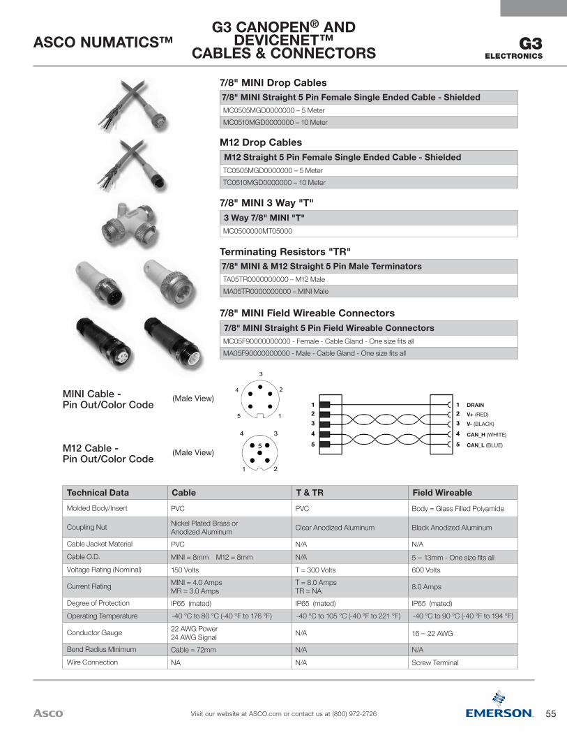
55
ASCO NUMATICS™
Visit our website at ASCO.com or contact us at (800) 972-2726
G3ELECTRONICS
V+ (RED)DRAIN
V- (BLACK)
CAN_H (WHITE)
CAN_L (BLUE)
Technical Data Cable T & TR Field WireableMolded Body/Insert PVC PVC Body = Glass Filled Polyamide
Coupling Nut Nickel Plated Brass or Anodized Aluminum Clear Anodized Aluminum Black Anodized Aluminum
Cable Jacket Material PVC N/A N/ACable O.D. MINI = 8mm M12 = 8mm N/A 5 – 13mm - One size fits allVoltage Rating (Nominal) 150 Volts T = 300 Volts 600 Volts
Current Rating MINI = 4.0 Amps MR = 3.0 Amps
T = 8.0 Amps TR = NA 8.0 Amps
Degree of Protection IP65 (mated) IP65 (mated) IP65 (mated)Operating Temperature -40 °C to 80 °C (-40 °F to 176 °F) -40 °C to 105 °C (-40 °F to 221 °F) -40 °C to 90 °C (-40 °F to 194 °F)
Conductor Gauge 22 AWG Power 24 AWG Signal N/A 16 – 22 AWG
Bend Radius Minimum Cable = 72mm N/A N/AWire Connection NA N/A Screw Terminal
(Male View)MINI Cable - Pin Out/Color Code
7/8" MINI Straight 5 Pin Female Single Ended Cable - ShieldedMC0505MGD0000000 – 5 MeterMC0510MGD0000000 – 10 Meter
7/8" MINI Drop Cables
G3 CANOPEN® AND DEVICENET™
CABLES & CONNECTORS
M12 Straight 5 Pin Female Single Ended Cable - ShieldedTC0505MGD0000000 – 5 MeterTC0510MGD0000000 – 10 Meter
M12 Drop Cables
3 Way 7/8" MINI "T"MC0500000MT05000
7/8" MINI 3 Way "T"
7/8" MINI & M12 Straight 5 Pin Male TerminatorsTA05TR0000000000 – M12 MaleMA05TR0000000000 – MINI Male
Terminating Resistors "TR"
7/8" MINI Straight 5 Pin Field Wireable ConnectorsMC05F90000000000 - Female - Cable Gland - One size fits allMA05F90000000000 - Male - Cable Gland - One size fits all
7/8" MINI Field Wireable Connectors
(Male View)M12 Cable - Pin Out/Color Code
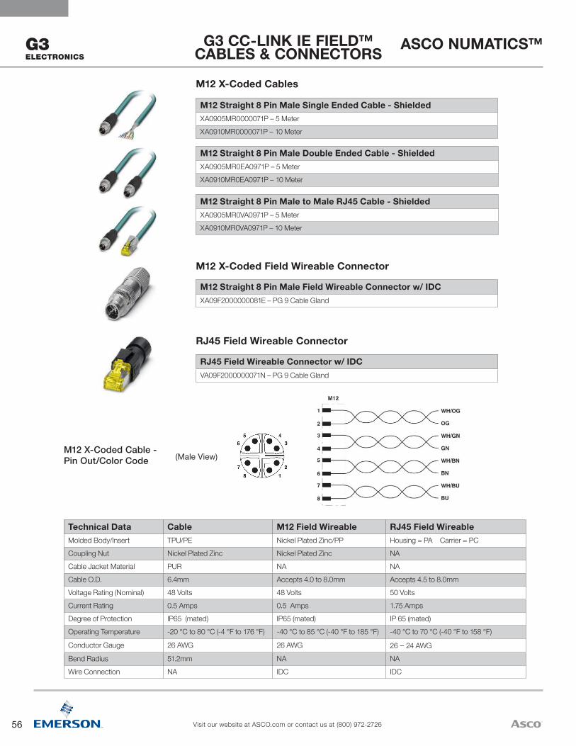
56
ASCO NUMATICS™
Visit our website at ASCO.com or contact us at (800) 972-2726
G3 ELECTRONICS
Technical Data Cable M12 Field Wireable RJ45 Field WireableMolded Body/Insert TPU/PE Nickel Plated Zinc/PP Housing = PA Carrier = PC Coupling Nut Nickel Plated Zinc Nickel Plated Zinc NACable Jacket Material PUR NA NACable O.D. 6.4mm Accepts 4.0 to 8.0mm Accepts 4.5 to 8.0mm Voltage Rating (Nominal) 48 Volts 48 Volts 50 Volts Current Rating 0.5 Amps 0.5 Amps 1.75 AmpsDegree of Protection IP65 (mated) IP65 (mated) IP 65 (mated)Operating Temperature -20 °C to 80 °C (-4 °F to 176 °F) -40 °C to 85 °C (-40 °F to 185 °F) -40 °C to 70 °C (-40 °F to 158 °F)
Conductor Gauge 26 AWG 26 AWG 26 – 24 AWGBend Radius 51.2mm NA NAWire Connection NA IDC IDC
(Male View)M12 X-Coded Cable - Pin Out/Color Code
RJ45 Field Wireable Connector w/ IDCVA09F2000000071N – PG 9 Cable Gland
RJ45 Field Wireable Connector
M12 Straight 8 Pin Male Field Wireable Connector w/ IDCXA09F2000000081E – PG 9 Cable Gland
M12 X-Coded Field Wireable Connector
M12 Straight 8 Pin Male to Male RJ45 Cable - ShieldedXA0905MR0VA0971P – 5 Meter XA0910MR0VA0971P – 10 Meter
M12 Straight 8 Pin Male Double Ended Cable - ShieldedXA0905MR0EA0971P – 5 Meter XA0910MR0EA0971P – 10 Meter
M12 Straight 8 Pin Male Single Ended Cable - ShieldedXA0905MR0000071P – 5 Meter XA0910MR0000071P – 10 Meter
M12 X-Coded Cables
G3 CC-LINK IE FIELD™ CABLES & CONNECTORS
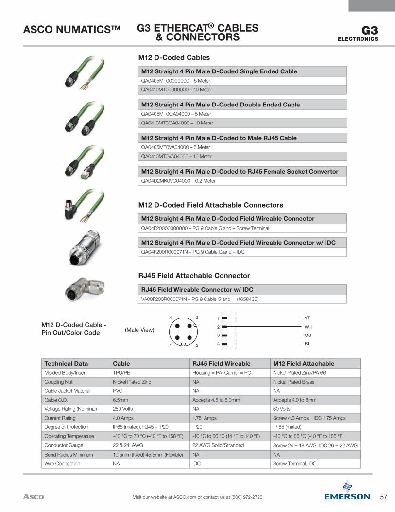
57
ASCO NUMATICS™
Visit our website at ASCO.com or contact us at (800) 972-2726
G3ELECTRONICS
YE
WH
OG
BU
2
1
4
3
4 3
1 2
Technical Data Cable RJ45 Field Wireable M12 Field AttachableMolded Body/Insert TPU/PE Housing = PA Carrier = PC Nickel Plated Zinc/PA 66 Coupling Nut Nickel Plated Zinc NA Nickel Plated BrassCable Jacket Material PVC NA NACable O.D. 6.5mm Accepts 4.5 to 8.0mm Accepts 4.0 to 8mm Voltage Rating (Nominal) 250 Volts NA 60 Volts Current Rating 4.0 Amps 1.75 Amps Screw 4.0 Amps IDC 1.75 AmpsDegree of Protection IP65 (mated), RJ45 – IP20 IP20 IP 65 (mated)Operating Temperature -40 °C to 70 °C (-40 °F to 158 °F) -10 °C to 60 °C (14 °F to 140 °F) -40 °C to 85 °C (-40 °F to 185 °F)
Conductor Gauge 22 & 24 AWG 22 AWG Solid/Stranded Screw 24 – 18 AWG IDC 26 – 22 AWGBend Radius Minimum 19.5mm (fixed) 45.5mm (Flexible) NA NAWire Connection NA IDC Screw Terminal, IDC
(Male View)M12 D-Coded Cable - Pin Out/Color Code
RJ45 Field Wireable Connector w/ IDCVA08F200R000071N – PG 9 Cable Gland (1658435)
RJ45 Field Attachable Connector
M12 Straight 4 Pin Male D-Coded Field Wireable Connector w/ IDCQA04F200R000071N – PG 9 Cable Gland – IDC
M12 Straight 4 Pin Male D-Coded Field Wireable ConnectorQA04F20000000000 – PG 9 Cable Gland – Screw Terminal
M12 D-Coded Field Attachable Connectors
M12 Straight 4 Pin Male D-Coded to RJ45 Female Socket ConvertorQA04D2MK0VC04000 – 0.2 Meter
M12 Straight 4 Pin Male D-Coded to Male RJ45 CableQA0405MT0VA04000 – 5 MeterQA0410MT0VA04000 – 10 Meter
M12 Straight 4 Pin Male D-Coded Double Ended CableQA0405MT0QA04000 – 5 MeterQA0410MT0QA04000 – 10 Meter
M12 Straight 4 Pin Male D-Coded Single Ended CableQA0405MT00000000 – 5 MeterQA0410MT00000000 – 10 Meter
M12 D-Coded Cables
G3 ETHERCAT® CABLES & CONNECTORS
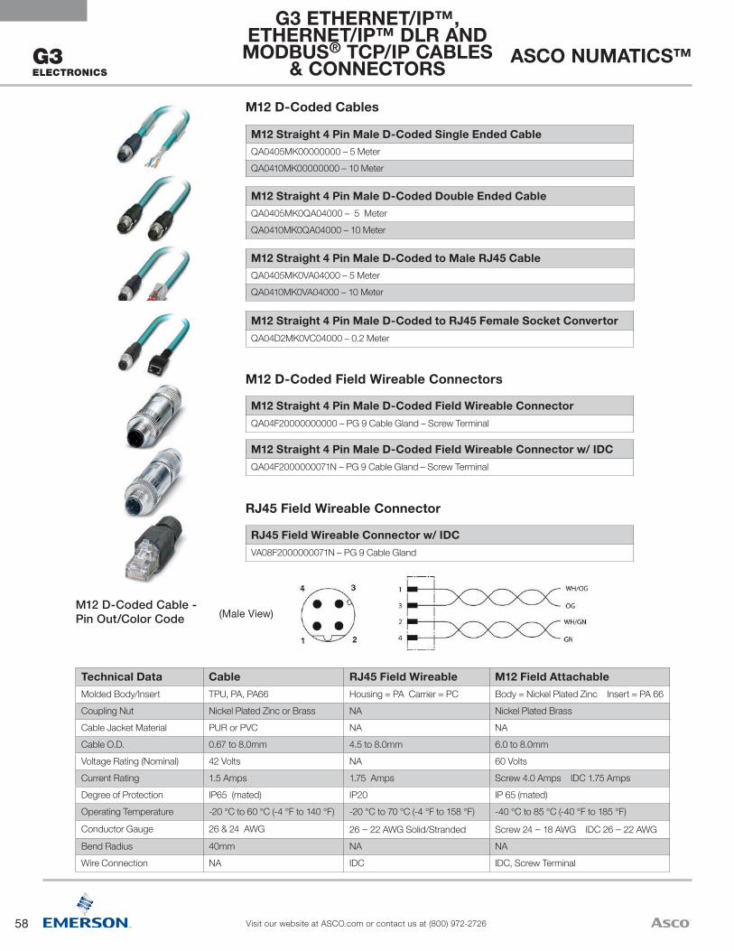
58
ASCO NUMATICS™
Visit our website at ASCO.com or contact us at (800) 972-2726
G3 ELECTRONICS
Technical Data Cable RJ45 Field Wireable M12 Field AttachableMolded Body/Insert TPU, PA, PA66 Housing = PA Carrier = PC Body = Nickel Plated Zinc Insert = PA 66 Coupling Nut Nickel Plated Zinc or Brass NA Nickel Plated BrassCable Jacket Material PUR or PVC NA NACable O.D. 0.67 to 8.0mm 4.5 to 8.0mm 6.0 to 8.0mm Voltage Rating (Nominal) 42 Volts NA 60 Volts Current Rating 1.5 Amps 1.75 Amps Screw 4.0 Amps IDC 1.75 AmpsDegree of Protection IP65 (mated) IP20 IP 65 (mated)Operating Temperature -20 °C to 60 °C (-4 °F to 140 °F) -20 °C to 70 °C (-4 °F to 158 °F) -40 °C to 85 °C (-40 °F to 185 °F)
Conductor Gauge 26 & 24 AWG 26 – 22 AWG Solid/Stranded Screw 24 – 18 AWG IDC 26 – 22 AWGBend Radius 40mm NA NAWire Connection NA IDC IDC, Screw Terminal
(Male View)M12 D-Coded Cable - Pin Out/Color Code
RJ45 Field Wireable Connector w/ IDCVA08F2000000071N – PG 9 Cable Gland
RJ45 Field Wireable Connector
M12 Straight 4 Pin Male D-Coded Field Wireable ConnectorQA04F20000000000 – PG 9 Cable Gland – Screw Terminal
M12 Straight 4 Pin Male D-Coded Field Wireable Connector w/ IDCQA04F2000000071N – PG 9 Cable Gland – Screw Terminal
M12 D-Coded Field Wireable Connectors
M12 Straight 4 Pin Male D-Coded to RJ45 Female Socket ConvertorQA04D2MK0VC04000 – 0.2 Meter
M12 Straight 4 Pin Male D-Coded to Male RJ45 CableQA0405MK0VA04000 – 5 MeterQA0410MK0VA04000 – 10 Meter
M12 Straight 4 Pin Male D-Coded Double Ended CableQA0405MK0QA04000 – 5 MeterQA0410MK0QA04000 – 10 Meter
M12 Straight 4 Pin Male D-Coded Single Ended CableQA0405MK00000000 – 5 MeterQA0410MK00000000 – 10 Meter
M12 D-Coded Cables
G3 ETHERNET/IP™, ETHERNET/IP™ DLR AND
MODBUS® TCP/IP CABLES & CONNECTORS

59
ASCO NUMATICS™
Visit our website at ASCO.com or contact us at (800) 972-2726
G3ELECTRONICS
M12 to M12
1
2
3
4
1yellow
shield
orange
white
blue2
3
4
RJ45 to M12
1
2
3
4
1yellow
shield
orange
white
blue
2
3
4
12344 3
1 2
Technical Data Cable RJ45 Field Attachable M12 Field Attachable
Molded Body/Insert N/A Housing = PA Carrier = PC Body = Nickel Plated Zinc Insert = PA 66
Coupling Nut Nickel Plated Zinc or Brass N/A Nickel Plated BrassCable Jacket Material PUR N/A N/ACable O.D. 6.5mm Accepts 4.5 to 8.0mm Accepts 6.0 to 8mm Voltage Rating (Nominal) N/A N/A 60 VoltsCurrent Rating N/A 1.75 Amps Screw 4.0 Amps IDC 1.75 AmpsDegree of Protection IP65 (mated), RJ45 – IP20 IP20 IP 65 (mated)Operating Temperature -25 °C to 60 °C (-13 °F to 140 °F) -10 °C to 60 °C (14 °F to 140 °F) -40 °C to 85 °C (-40 °F to 185 °F)
Conductor Gauge 22 AWG 22 AWG Solid/Stranded Screw 24 – 18 AWG IDC 26-22 AWGBend Radius Minimum 45.5mm N/A N/AWire Connection N/A IDC Screw Terminal, IDC
(Male View)M12 D-Coded Cable & RJ45 Pin Out/Color Code
RJ45 Field Wireable Connector w/ IDCVA08F200R000071N – PG 9 Cable Gland
RJ45 Field Attachable Connectors
M12 Straight 4 Pin Male D-Coded Field Wireable Connector w/ IDCQA04F200R000071N – PG 9 Cable Gland – IDC
M12 Straight 4 Pin Male D-Coded Field Wireable ConnectorQA04F20000000000 – PG 9 Cable Gland – Screw Terminal
M12 D-Coded Field Attachable Connectors
M12 Straight 4 Pin Male D-Coded to RJ45 Female Socket ConverterQA04D2MK0VC04000 – 0.2 Meter
M12 Straight 4 Pin Male D-Coded to Male RJ45 CableQA0405MS0VA04000 – 5 MeterQA0410MS0VA04000 – 10 Meter
M12 Straight 4 Pin Male D-Coded Double Ended CableQA0405MS0QA04000 – 5 MeterQA0410MS0QA04000 – 10 Meter
M12 D-Coded Cables
G3 ETHERNET POWERLINK®
CABLES & CONNECTORS
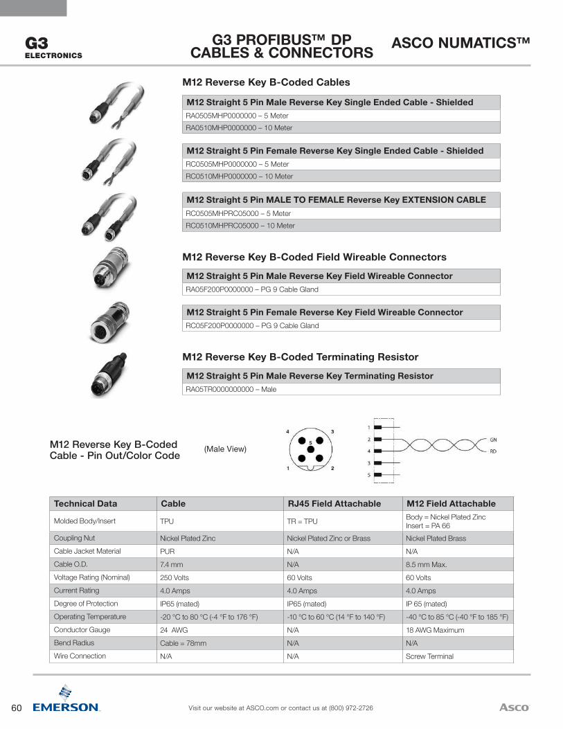
60
ASCO NUMATICS™
Visit our website at ASCO.com or contact us at (800) 972-2726
G3 ELECTRONICS
Technical Data Cable RJ45 Field Attachable M12 Field Attachable
Molded Body/Insert TPU TR = TPU Body = Nickel Plated Zinc Insert = PA 66
Coupling Nut Nickel Plated Zinc Nickel Plated Zinc or Brass Nickel Plated BrassCable Jacket Material PUR N/A N/ACable O.D. 7.4 mm N/A 8.5 mm Max.Voltage Rating (Nominal) 250 Volts 60 Volts 60 VoltsCurrent Rating 4.0 Amps 4.0 Amps 4.0 AmpsDegree of Protection IP65 (mated) IP65 (mated) IP 65 (mated)Operating Temperature -20 °C to 80 °C (-4 °F to 176 °F) -10 °C to 60 °C (14 °F to 140 °F) -40 °C to 85 °C (-40 °F to 185 °F)Conductor Gauge 24 AWG N/A 18 AWG MaximumBend Radius Cable = 78mm N/A N/AWire Connection N/A N/A Screw Terminal
(Male View)M12 Reverse Key B-Coded Cable - Pin Out/Color Code
M12 Straight 5 Pin Male Reverse Key Terminating ResistorRA05TR0000000000 – Male
M12 Reverse Key B-Coded Terminating Resistor
M12 Straight 5 Pin Female Reverse Key Field Wireable ConnectorRC05F200P0000000 – PG 9 Cable Gland
M12 Straight 5 Pin Male Reverse Key Field Wireable ConnectorRA05F200P0000000 – PG 9 Cable Gland
M12 Reverse Key B-Coded Field Wireable Connectors
M12 Straight 5 Pin MALE TO FEMALE Reverse Key EXTENSION CABLERC0505MHPRC05000 – 5 MeterRC0510MHPRC05000 – 10 Meter
M12 Straight 5 Pin Female Reverse Key Single Ended Cable - ShieldedRC0505MHP0000000 – 5 MeterRC0510MHP0000000 – 10 Meter
M12 Straight 5 Pin Male Reverse Key Single Ended Cable - ShieldedRA0505MHP0000000 – 5 MeterRA0510MHP0000000 – 10 Meter
M12 Reverse Key B-Coded Cables
G3 PROFIBUS™ DP CABLES & CONNECTORS
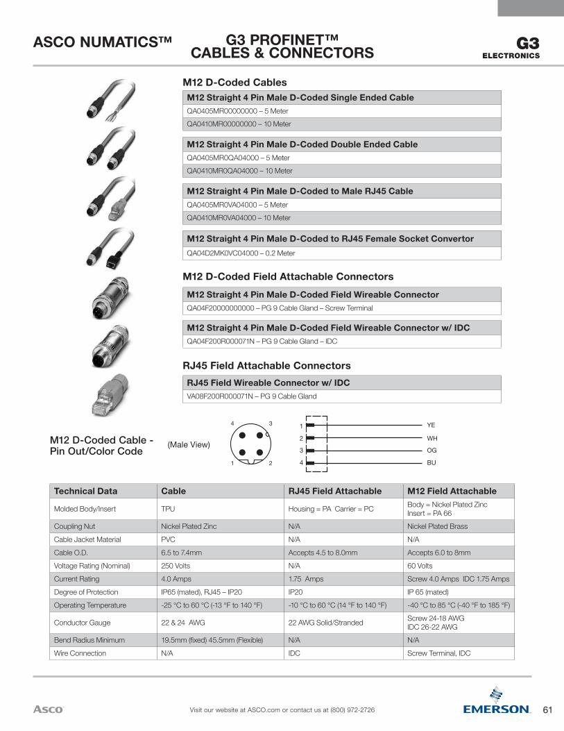
61
ASCO NUMATICS™
Visit our website at ASCO.com or contact us at (800) 972-2726
G3ELECTRONICS
YE
WH
OG
BU
2
1
4
3
4 3
1 2
Technical Data Cable RJ45 Field Attachable M12 Field Attachable
Molded Body/Insert TPU Housing = PA Carrier = PC Body = Nickel Plated Zinc Insert = PA 66
Coupling Nut Nickel Plated Zinc N/A Nickel Plated BrassCable Jacket Material PVC N/A N/ACable O.D. 6.5 to 7.4mm Accepts 4.5 to 8.0mm Accepts 6.0 to 8mm Voltage Rating (Nominal) 250 Volts N/A 60 VoltsCurrent Rating 4.0 Amps 1.75 Amps Screw 4.0 Amps IDC 1.75 AmpsDegree of Protection IP65 (mated), RJ45 – IP20 IP20 IP 65 (mated)Operating Temperature -25 °C to 60 °C (-13 °F to 140 °F) -10 °C to 60 °C (14 °F to 140 °F) -40 °C to 85 °C (-40 °F to 185 °F)
Conductor Gauge 22 & 24 AWG 22 AWG Solid/Stranded Screw 24-18 AWG IDC 26-22 AWG
Bend Radius Minimum 19.5mm (fixed) 45.5mm (Flexible) N/A N/AWire Connection N/A IDC Screw Terminal, IDC
(Male View)M12 D-Coded Cable - Pin Out/Color Code
RJ45 Field Wireable Connector w/ IDCVA08F200R000071N – PG 9 Cable Gland
RJ45 Field Attachable Connectors
M12 Straight 4 Pin Male D-Coded Field Wireable Connector w/ IDCQA04F200R000071N – PG 9 Cable Gland – IDC
M12 Straight 4 Pin Male D-Coded Field Wireable ConnectorQA04F20000000000 – PG 9 Cable Gland – Screw Terminal
M12 D-Coded Field Attachable Connectors
M12 Straight 4 Pin Male D-Coded to RJ45 Female Socket ConvertorQA04D2MK0VC04000 – 0.2 Meter
M12 Straight 4 Pin Male D-Coded to Male RJ45 CableQA0405MR0VA04000 – 5 MeterQA0410MR0VA04000 – 10 Meter
M12 Straight 4 Pin Male D-Coded Double Ended CableQA0405MR0QA04000 – 5 MeterQA0410MR0QA04000 – 10 Meter
M12 Straight 4 Pin Male D-Coded Single Ended CableQA0405MR00000000 – 5 MeterQA0410MR00000000 – 10 Meter
M12 D-Coded Cables
G3 PROFINET™ CABLES & CONNECTORS

62
ASCO NUMATICS™
Visit our website at ASCO.com or contact us at (800) 972-2726
G3 ELECTRONICS
M12 to M8 “Y” SplitterTA0400000KC03000
M12 to M12 “Y” Splitter, 21mm SpacingTA0500000JC05000
I/O Splitters
M12 90° 4 Pin Male Field Wireable Connector, Screw TerminalTB04F10000000000 – PG 7 Cable GlandTB04F20000000000 – PG 9 Cable Gland
M12 Straight 4 Pin Male Field Wireable Connector, Screw TerminalTA04F10000000000 – PG 7 Cable GlandTA04F20000000000 – PG 9 Cable Gland
M12 Straight 4 Pin Male Field Wireable Connector, IDC ConnectionTA04F2000000081E – PG 9 Cable Gland w/ SPEEDCON® connector technology
I/O Connectors
M12 Straight 3 Pin Male to M8 3 Pin Straight Female ExtensionTC03E5MIEPA0371P – 1.5 MeterTC0303MIEPA0371P – 3 Meter
M12 Straight 4 Pin Male to Female Cable ExtensionTC04E5MIETA0471P – 1.5 MeterTC0403MIETA0471P – 3 Meter
M12 90° 4 Pin Male Single Ended Cable, Euro Color CodeTB04E5MIE000071P – 1.5 MeterTB0403MIE000071P – 3 MeterTB0405MIE000071P – 5 Meter
M12 Straight 4 Pin Male Single Ended Cable, Euro Color CodeTA04E5MIE000071P – 1.5 MeterTA0403MIE000071P – 3 MeterTA0405MIE000071P – 5 Meter
I/O Cables with SPEEDCON® Connector Technology
G3 I/O CABLES & CONNECTORS

63
ASCO NUMATICS™
Visit our website at ASCO.com or contact us at (800) 972-2726
G3ELECTRONICS
NOTE: XX denotes allowable length. See pages 101 & 102.
M12 to M8 Cable Splitter - Pin Out TA04XXMIEKC03000(Male to Female View)
M12 to M12 Cable Splitter - Pin Out TA04XXMIEJC04000(Male to Female View)
M12 Field Wireable (IDC) - Pin Out TA04F2000000081E (SPEEDCON®)(Male View)
M12 to M8 "Y" Splitter - Pin Out TA0400000KC03000(Male to Female View)
M12 to M12 "Y" Splitter - Pin Out TA0500000JC05000(Male to Female View)
M12 Cable - Pin Out/Color CodeTC03XXMIEPA0371P(Male to Female View)
M12 Cable - Pin Out/Color CodeTC03XXMIEPA0371P(Male to Female View)
M12 Cable - Pin Out/Color CodeTA04XXMIE0000000, TB04XXMIE0000000(Male View)
I/O Cable Connector Pin Out Diagrams
Wire Stripper Tool140-1097
M12 Cable Splitter, 2 Straight M8 Female ConnectorsTA04D3MIEKC03000 – 0.3 MeterTA04E5MIEKC03000 – 1.5 MeterTA0403MIEKC03000 – 3.0 Meter
M12 Cable Splitter, 2 Straight M12 Female Connectors TA04D3MIEJC04000 – 0.3 MeterTA04E5MIEJC04000 – 1.5 MeterTA0403MIEJC04000 – 3.0 Meter

64
ASCO NUMATICS™
Visit our website at ASCO.com or contact us at (800) 972-2726
G3 ELECTRONICS
Technical Data Wire StripperUse with PVC Insulation
Stripping Range 28 AWG to 10 AWG
Cutting Range (Flexible) 10 AWG
Cutting Range (Rigid) 12 AWG
Technical Data I/O "Y" Splitter I/O Cable SplitterMolded Body/Insert TPU TPU
Coupling Nut Nickel Plated Zinc Nickel Plated Zinc
Cable Jacket Material NA PUR
Cable O.D. NA 4.40mm
Voltage Rating 60 Volts 60 Volts
Current Rating (Cond.) 3.0 Amps 3.0 Amps
Degree of Protection IP67 (mated) IP67 (mated)
Operating Temperature -25 ºC to 90 ºC (-13 °F to 194 °F) -25 ºC to 80 ºC (-13 °F to 176 °F)
Conductor Gauge NA 22 AWG or 24 AWG
Bend Radius NA 44mm
Technical Data M12 Cables M12/M8 Cables M12 ConnectorsMolded Body/Insert TPU TPU Polyamide (or) PA 66
Coupling Nut Nickel Plated Zinc Nickel Plated Zinc Nickel Plated Zinc
Cable Jacket Material PUR PUR NA
Cable O.D. 4.70mm 4.70mm PG7 4.0 to 6.0mmPG9 4.0 to 8.0mm
Voltage Rating 250 Volts 60 Volts 50 Volts
Current Rating (Cond.) 4.0 Amps 3.0 Amps 4.0 Amps
Degree of Protection IP65 (mated) IP65 (mated) IP67 (mated)
Operating Temperature -25 ºC to 80 ºC (-13 °F to 176 °F) (fixed instl.)
-25 ºC to 80 ºC (-13 °F to 176 °F) (fixed instl.) -25 ºC to 80 ºC (-13 °F to 176 °F)
Conductor Gauge 22 AWG 22 AWG 22 AWG Min. 18 AWG Max.
Bend Radius 47mm 47mm NA
Cable and Connector Technical Data

65
ASCO NUMATICS™
Visit our website at ASCO.com or contact us at (800) 972-2726
G3ELECTRONICS
Conductor CablePin 11 Gray/PinkPin 12 Green/YellowPin 13 White/GreenPin 14 Brown/GreenPin 15 White/Yellow
Pin 16 Yellow/Brown
Pin 17 White/GrayPin 18 Gray/BrownPin 19 Red/Blue
Conductor CablePin 1 WhitePin 2 BrownPin 3 GreenPin 4 YellowPin 5 Gray
Pin 6 Pink
Pin 7 BluePin 8 RedPin 9 BlackPin 10 Purple
(Female View)
(Male View)M23 19 Pin Cable - Pin Out/Color Code
Technical Data Cable ConnectorMolded Body/Insert PA66 PBT
Coupling Nut Gadolinium-Zinc Plated Brass Gadolinium-Zinc Plated Brass/ Nickel Plated Brass
Cable Jacket Material PUR/PVC N/ACable O.D. 10.5mm Accepts 10.0 to 12.0mmVoltage Rating (Nominal) 150 Volts 150 Volts
Current Rating 8.0 Amps 8.0 Amps
Degree of Protection IP65 (mated) IP65 (mated)Operating Temperature -40 °C to 80 °C (-40 °F to 176 °F) -20 °C to 80 °C (-4 °F to 176 °F)Conductor Gauge 18 & 20 AWG 18 AWGBend Radius Minimum 78.75mm N/AWire Connection N/A Solder Cup
M23 19 Pin Female to Male Double Ended CableCC1902MI0CE19000 – 2 MeterCC1905MI0CE19000 – 5 MeterCC1910MI0CE19000 – 10 Meter
M23 19 Pin Male Single Ended CableCE1905MI00000000 – 5 MeterCE1910MI00000000 – 10 Meter
M23 19 Pin Female Single Ended CableCC1905MI00000000 – 5 MeterCC1910MI00000000 – 10 Meter
M23 19 Pin Cables
M23 19 PIN CABLES & CONNECTORS
M23 19 Pin Female Field Wireable Connector, Solder CupCC19000000000000 – PG 13.5 Cable Gland
M23 19 Pin Connectors

66
ASCO NUMATICS™
Visit our website at ASCO.com or contact us at (800) 972-2726
G3 ELECTRONICS
Technical Data Cable Connectors Bulk Cable Molded Body / Insert TPU Zinc - Nickel Plated N/ACoupling Nut Zinc - Nickel Plated Brass - Nickel Plated N/ACable Jacket Material PUR N/A Gray RAL 7001Cable O.D. 6.70mm N/A 6.70mmVoltage Rating (Nominal) 60 Volts 60 Volts 60 VoltsCurrent Rating 4.0 Amps 4.0 Amps 4.0 AmpsDegree of Protection IP65 (mated) IP65 (mated) IP65 (terminated)Operating Temperature -40 °C to 80 °C (-40 °F to 176 °F) -40 °C to 80 °C (-40 °F to 176 °F) -20 °C to 75 °C (-4 °F to 167 °F)
Conductor Gauge 24 AWG Signal22 AWG Power 26 – 20 AWG 24 AWG Signal
22 AWG PowerBend Radius 67mm N/A 67mmNo. of Bending Cycles 5 Million N/A 5 Million
Technical Data
* NOTE: Length of field wired cables should not exceed the maximum length of 30 meters for total Sub-bus communications link. See appropriate technical manual for Sub-bus length requirements. The cable assemblies and Bulk cable are the only approved cables for the G3 Sub-bus link. See technical document TDG3SBWD1-0EN for proper installation and wiring of field wireable connectors.
Bulk Sub-bus Cable*
000550MGD0005000 – 50 Meter Length0005A0MGD0005000 – 100 Meter Length
M12 90º 5 Pin Male Field Wireable Connector, Spring Cage TB05F2000000071V – PG9 Cable Gland
M12 90º 5 Pin Female Field Wireable Connector, Spring CageTD05F2000000071V – PG9 Cable Gland
M12 Straight 5 Pin Male Field Wireable Connector, Spring CageTA05F2000000071V – PG9 Cable Gland
M12 Straight 5 Pin Female Field Wireable Connector, Spring CageTC05F2000000071V – PG9 Cable Gland
M12 Straight 5 Pin Male to Female Sub-bus Cable - ShieldedTA0501MGDTC0571P – 1 MeterTA0505MGDTC0571P – 5 MeterTA0510MGDTC0571P – 10 Meter
Sub-bus Cables
SUB-BUS CABLES & CONNECTORS

67
ASCO NUMATICS™
Visit our website at ASCO.com or contact us at (800) 972-2726
G3ELECTRONICS
Power Supply
Cable Description Example Cable Part # PageMC0405MAC0000000TA0401MA0MC0471TMC0505MGD0000000TA04F2000000081ETA0405MIE000071PTA0501MGDTC0571P
Power Cable 97Alternate Sub-bus Power Option 98DeviceNet™/CANopen® Communication Cable 100I/O Field Wireable Connector 107I/O Connector with Molded Cable 107Sub-bus Cable 111
Example Sub-bus Layout and Cabling (DeviceNet™/CANopen® Network)
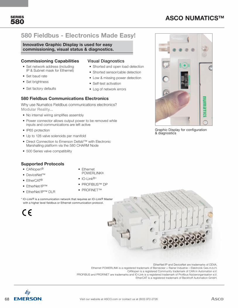
68
ASCO NUMATICS™
Visit our website at ASCO.com or contact us at (800) 972-2726
SERIES
580
EtherNet/IP and DeviceNet are trademarks of ODVA. Ethernet POWERLINK is a registered trademark of Bernecker + Rainer Industrie – Elektronik Ges.m.b.H.
CANopen is a registered Community trademark of CAN in Automation e.V. PROFIBUS and PROFINET are trademarks and IO-Link is a registered trademark of Profibus Nutzerorganisation e.V.
EtherCAT is a registered trademark of Beckhoff Automation GmbH.
Graphic Display for configuration & diagnostics
* IO-Link® is a communication network that requires an IO-Link® Master with a higher level fieldbus or Ethernet communication protocol.
• CANopen®
• DeviceNet™ • EtherCAT®
• EtherNet/IP™• EtherNet/IP™ DLR
• Ethernet POWERLINK®
• IO-Link®*• PROFIBUS™ DP• PROFINET™
Supported Protocols
580 Fieldbus Communications ElectronicsWhy use Numatics Fieldbus communications electronics? Modular Reality...• No internal wiring simplifies assembly• Power connector allows output power to be removed while
inputs and communications are left active• IP65 protection• Up to 128 valve solenoids per manifold• Direct Connection to Emerson DeltaV™ with Electronic
Marshalling platform via the 580 CHARM Node• 500 Series valve compatibility
Commissioning Capabilities• Set network address (including
IP & Subnet mask for Ethernet)• Set baud rate• Set brightness
• Set factory defaults
Visual Diagnostics• Shorted and open load detection• Shorted sensor/cable detection• Low & missing power detection• Self-test activation• Log of network errors
580 Fieldbus - Electronics Made Easy!Innovative Graphic Display is used for easy commissioning, visual status & diagnostics.
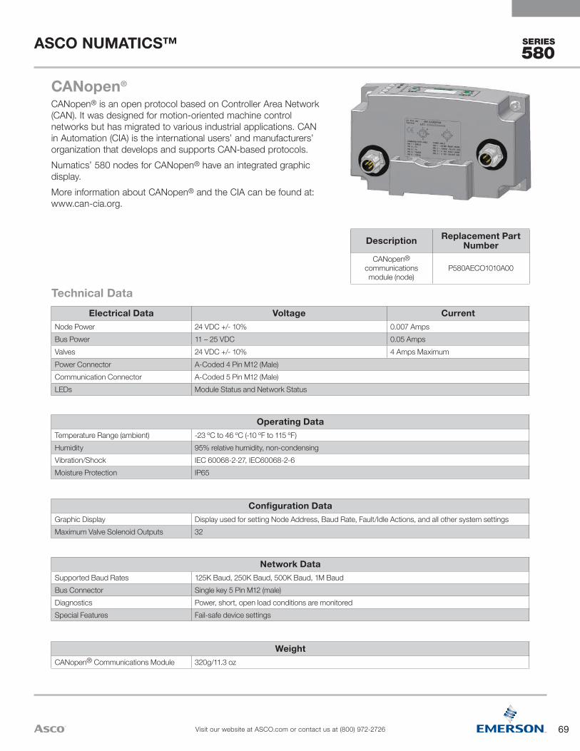
69
ASCO NUMATICS™
Visit our website at ASCO.com or contact us at (800) 972-2726
SERIES
580
CANopen®
CANopen® is an open protocol based on Controller Area Network (CAN). It was designed for motion-oriented machine control networks but has migrated to various industrial applications. CAN in Automation (CIA) is the international users’ and manufacturers’ organization that develops and supports CAN-based protocols.Numatics’ 580 nodes for CANopen® have an integrated graphic display.More information about CANopen® and the CIA can be found at: www.can-cia.org.
Technical DataElectrical Data Voltage Current
Node Power 24 VDC +/- 10% 0.007 AmpsBus Power 11 – 25 VDC 0.05 AmpsValves 24 VDC +/- 10% 4 Amps MaximumPower Connector A-Coded 4 Pin M12 (Male)Communication Connector A-Coded 5 Pin M12 (Male)LEDs Module Status and Network Status
Operating DataTemperature Range (ambient) -23 ºC to 46 ºC (-10 ºF to 115 ºF) Humidity 95% relative humidity, non-condensingVibration/Shock IEC 60068-2-27, IEC60068-2-6Moisture Protection IP65
Configuration DataGraphic Display Display used for setting Node Address, Baud Rate, Fault/Idle Actions, and all other system settingsMaximum Valve Solenoid Outputs 32
Network DataSupported Baud Rates 125K Baud, 250K Baud, 500K Baud, 1M BaudBus Connector Single key 5 Pin M12 (male)Diagnostics Power, short, open load conditions are monitoredSpecial Features Fail-safe device settings
WeightCANopen® Communications Module 320g/11.3 oz
Description Replacement Part Number
CANopen® communications module (node)
P580AECO1010A00
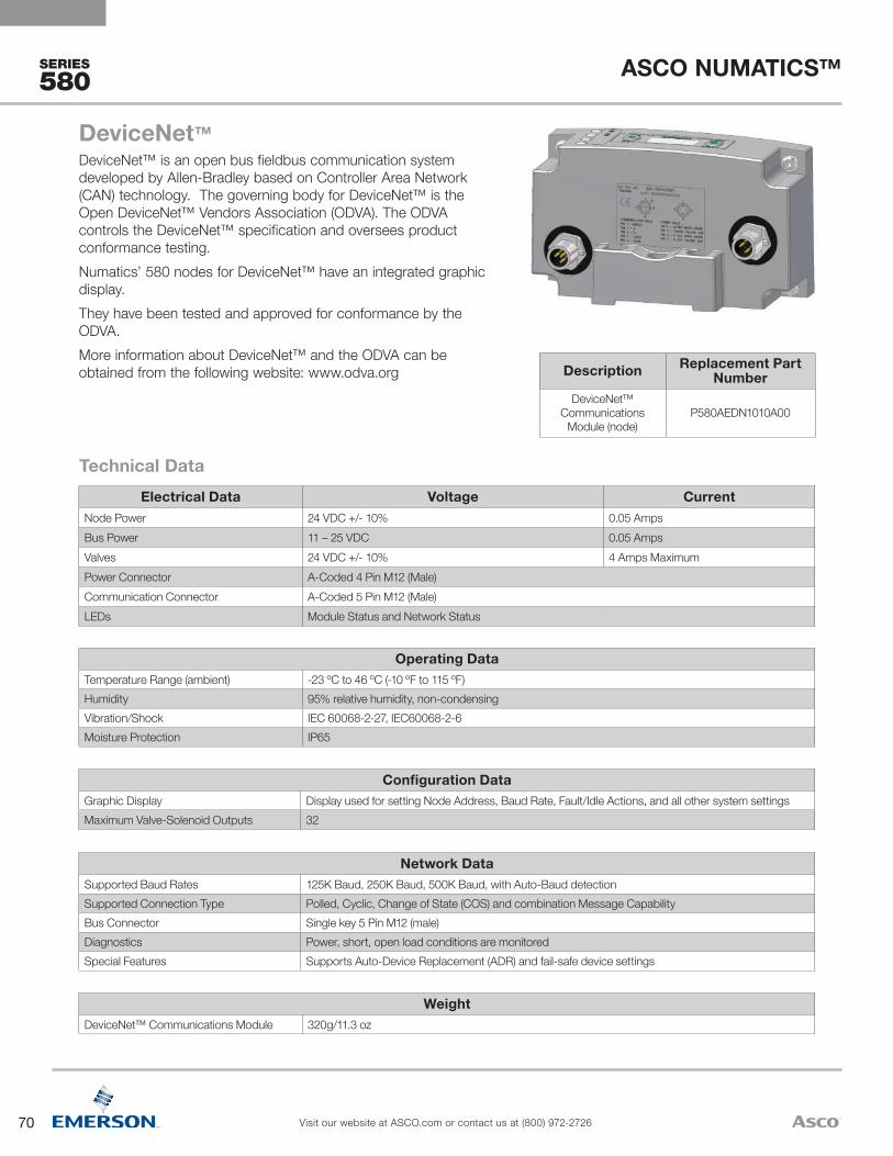
70
ASCO NUMATICS™
Visit our website at ASCO.com or contact us at (800) 972-2726
SERIES
580
WeightDeviceNet™ Communications Module 320g/11.3 oz
Network DataSupported Baud Rates 125K Baud, 250K Baud, 500K Baud, with Auto-Baud detectionSupported Connection Type Polled, Cyclic, Change of State (COS) and combination Message CapabilityBus Connector Single key 5 Pin M12 (male)Diagnostics Power, short, open load conditions are monitoredSpecial Features Supports Auto-Device Replacement (ADR) and fail-safe device settings
Configuration DataGraphic Display Display used for setting Node Address, Baud Rate, Fault/Idle Actions, and all other system settingsMaximum Valve-Solenoid Outputs 32
Operating DataTemperature Range (ambient) -23 ºC to 46 ºC (-10 ºF to 115 ºF)Humidity 95% relative humidity, non-condensingVibration/Shock IEC 60068-2-27, IEC60068-2-6Moisture Protection IP65
Electrical Data Voltage CurrentNode Power 24 VDC +/- 10% 0.05 AmpsBus Power 11 – 25 VDC 0.05 AmpsValves 24 VDC +/- 10% 4 Amps MaximumPower Connector A-Coded 4 Pin M12 (Male)Communication Connector A-Coded 5 Pin M12 (Male)LEDs Module Status and Network Status
Technical Data
Description Replacement Part Number
DeviceNet™ Communications
Module (node)P580AEDN1010A00
DeviceNet™DeviceNet™ is an open bus fieldbus communication system developed by Allen-Bradley based on Controller Area Network (CAN) technology. The governing body for DeviceNet™ is the Open DeviceNet™ Vendors Association (ODVA). The ODVA controls the DeviceNet™ specification and oversees product conformance testing.Numatics’ 580 nodes for DeviceNet™ have an integrated graphic display. They have been tested and approved for conformance by the ODVA.More information about DeviceNet™ and the ODVA can be obtained from the following website: www.odva.org
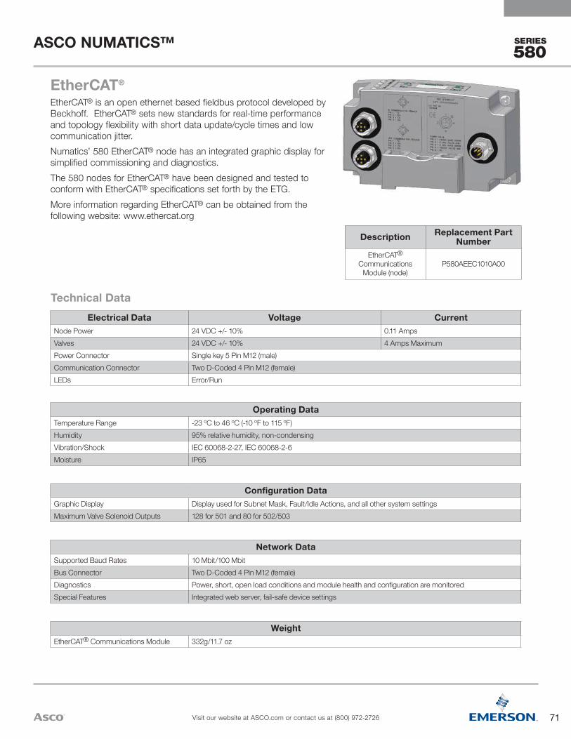
71
ASCO NUMATICS™
Visit our website at ASCO.com or contact us at (800) 972-2726
SERIES
580
EtherCAT®
EtherCAT® is an open ethernet based fieldbus protocol developed by Beckhoff. EtherCAT® sets new standards for real-time performance and topology flexibility with short data update/cycle times and low communication jitter. Numatics’ 580 EtherCAT® node has an integrated graphic display for simplified commissioning and diagnostics.The 580 nodes for EtherCAT® have been designed and tested to conform with EtherCAT® specifications set forth by the ETG.More information regarding EtherCAT® can be obtained from the following website: www.ethercat.org
Technical DataElectrical Data Voltage Current
Node Power 24 VDC +/- 10% 0.11 AmpsValves 24 VDC +/- 10% 4 Amps MaximumPower Connector Single key 5 Pin M12 (male)Communication Connector Two D-Coded 4 Pin M12 (female)LEDs Error/Run
Operating DataTemperature Range -23 ºC to 46 ºC (-10 ºF to 115 ºF)Humidity 95% relative humidity, non-condensingVibration/Shock IEC 60068-2-27, IEC 60068-2-6Moisture IP65
Configuration DataGraphic Display Display used for Subnet Mask, Fault/Idle Actions, and all other system settingsMaximum Valve Solenoid Outputs 128 for 501 and 80 for 502/503
Network DataSupported Baud Rates 10 Mbit/100 MbitBus Connector Two D-Coded 4 Pin M12 (female)Diagnostics Power, short, open load conditions and module health and configuration are monitoredSpecial Features Integrated web server, fail-safe device settings
WeightEtherCAT® Communications Module 332g/11.7 oz
Description Replacement Part Number
EtherCAT® Communications
Module (node)P580AEEC1010A00
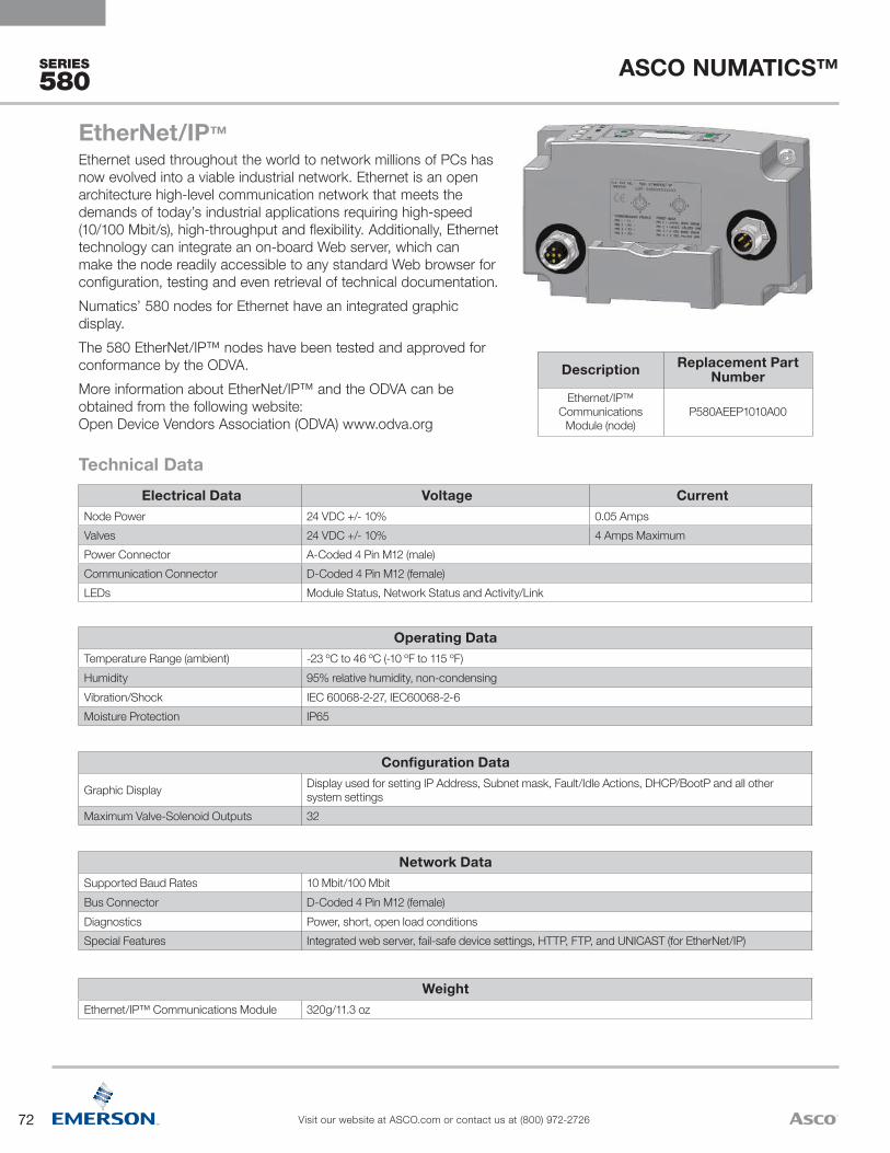
72
ASCO NUMATICS™
Visit our website at ASCO.com or contact us at (800) 972-2726
SERIES
580
EtherNet/IP™Ethernet used throughout the world to network millions of PCs has now evolved into a viable industrial network. Ethernet is an open architecture high-level communication network that meets the demands of today’s industrial applications requiring high-speed (10/100 Mbit/s), high-throughput and flexibility. Additionally, Ethernet technology can integrate an on-board Web server, which can make the node readily accessible to any standard Web browser for configuration, testing and even retrieval of technical documentation.Numatics’ 580 nodes for Ethernet have an integrated graphic display. The 580 EtherNet/IP™ nodes have been tested and approved for conformance by the ODVA.More information about EtherNet/IP™ and the ODVA can be obtained from the following website: Open Device Vendors Association (ODVA) www.odva.org
Technical DataElectrical Data Voltage Current
Node Power 24 VDC +/- 10% 0.05 AmpsValves 24 VDC +/- 10% 4 Amps MaximumPower Connector A-Coded 4 Pin M12 (male)Communication Connector D-Coded 4 Pin M12 (female) LEDs Module Status, Network Status and Activity/Link
Operating DataTemperature Range (ambient) -23 ºC to 46 ºC (-10 ºF to 115 ºF)Humidity 95% relative humidity, non-condensingVibration/Shock IEC 60068-2-27, IEC60068-2-6Moisture Protection IP65
Description Replacement Part Number
Ethernet/IP™Communications
Module (node)P580AEEP1010A00
Configuration Data
Graphic Display Display used for setting IP Address, Subnet mask, Fault/Idle Actions, DHCP/BootP and all other system settings
Maximum Valve-Solenoid Outputs 32
Network DataSupported Baud Rates 10 Mbit/100 MbitBus Connector D-Coded 4 Pin M12 (female)Diagnostics Power, short, open load conditionsSpecial Features Integrated web server, fail-safe device settings, HTTP, FTP, and UNICAST (for EtherNet/IP)
WeightEthernet/IP™ Communications Module 320g/11.3 oz

73
ASCO NUMATICS™
Visit our website at ASCO.com or contact us at (800) 972-2726
SERIES
580
WeightEtherNet/IP™ DLR Communications Module 337g/11.9 oz
Network DataSupported Baud Rates 10 Mbit/100 MbitBus Connector Two D-Coded 4 Pin M12 (female)Diagnostics Power, short, open load conditions and module health and configuration are monitored
Special Features Embedded two port switch, Device Level Ring (DLR) compatibility, Linear network topology, fail-safe device settings, integrated web server, HTTP, TFTP, UNICAST
Configuration DataGraphic Display Display used for setting IP address, Subnet Mask, Fault/Idle Actions, and all other system settingsMaximum Valve Solenoid Outputs 128 for 501 and 80 for 502/503
Operating DataTemperature Range -23 ºC to 46 ºC (-10 ºF to 115 ºF) Humidity 95% relative humidity, non-condensingVibration/Shock IEC 60068-2-27, IEC 60068-2-6Moisture IP65
Electrical Data Voltage CurrentNode Power 24 VDC +/- 10% 0.09 AmpsValves 24 VDC +/- 10% 4 Amps MaximumPower Connector A-Coded 4 Pin M12 (male)Communication Connector Two D-Coded 4 Pin M12 (female)LEDs Module Status, Network Status and Activity/Link
Technical Data
EtherNet/IP™ DLREtherNet/IP™ used throughout the world to network millions of PCs has now evolved into a viable industry network. EtherNet/IP™ is an open architecture high-level communication network that meets the demands of today’s industrial applications requiring high-speed (10/100 Mbit/s), high-throughput and flexibility. Additionally, EtherNet/IP™ technology can integrate an on-board Web server, which can make the node readily accessible to any standard Web browser for configuration, testing and even retrieval of technical documentation.Numatics’ 580 EtherNet/IP™ DLR (Device Level Ring) node with integrated display, has an embedded switch which allows the unit to be used in simplified networks with linear topology configurations (daisy chain). This technology alleviates the need for an external Ethernet switch device in a single subnet configuration. Additionally, the DLR compatibility allows the node to be used in a fault tolerant “ring” network, when using appropriate EtherNet/IP™ DLR scanners. DLR configuration allows communication recovery from a single point failure on the network ring (e.g. failed network connection or cable).The 580 EtherNet/IP™ nodes have been tested and approved for conformance by the ODVA.More information about EtherNet/IP and the ODVA can be obtained from the following website: www.odva.org
Description Replacement Part Number
EtherNet/IP™ DLR Communications
Module (node)P580AEED1010A00

74
ASCO NUMATICS™
Visit our website at ASCO.com or contact us at (800) 972-2726
SERIES
580
WeightPOWERLINK® Communications Module 328g/11.6 oz
Network DataSupported Baud Rates 10 Mbit/100 MbitBus Connector Two D-Coded 4 Pin M12 (female)Diagnostics Power, short, open load conditions and module health and configuration are monitoredSpecial Features Integrated web server and fail-safe device settings
Configuration DataGraphic Display Display used for setting IP address, Subnet Mask, Fault/Idle Actions, and all other system settingsMaximum Valve Solenoid Outputs 128 for 501 and 80 for 502/503
Operating DataTemperature Range (ambient) -23 ºC to 46 ºC (-10 ºF to 115 ºF) Humidity 95% relative humidity, non-condensingVibration/Shock IEC 60068-2-27, IEC60068-2-6Moisture IP65
Electrical Data Voltage CurrentNode Power 24 VDC +/- 10% 0.09 AmpsValves 24 VDC +/- 10% 4 Amps MaximumPower Connector Single Key 5 Pin M12 (male)Communication Connector Two D-Coded 4 Pin M12 (female)LEDs Error, Status and Activity/Link
Technical Data
Ethernet POWERLINK®
Ethernet POWERLINK® is an open fieldbus protocol designed by B&R for communication between automation control systems and the device level.Numatics' 580 nodes for Ethernet POWERLINK® have an integrated graphic display.The 580 Ethernet POWERLINK® nodes have been designed and tested to conform to the Ethernet POWERLINK® specifications available at EPSG group (Ethernet Powerlink Standardization Group). The certification process ensures interoperability for all Ethernet POWERLINK® devices and compatibility with B&R systems. More information regarding Ethernet POWERLINK® can be obtained from the following website: www.ethernet-powerlink.org
Description Replacement Part Number
POWERLINK® Communications
Module (node)P580AEPL1010A00

75
ASCO NUMATICS™
Visit our website at ASCO.com or contact us at (800) 972-2726
SERIES
580
WeightIO-Link® Communications Module Class A: 298g/10.5oz, Class B: 303g/10.7oz
Network DataSupported Baud Rates 38.4K
Diagnostics Power, short, open load conditions with both standard I/O mapped diagnostics and event based diagnostics
Special Features Fail-safe device settings
Configuration DataMaximum Valve Solenoid Outputs 32
Operating DataTemperature Range (ambient) -23 ºC to 46 ºC (-10 ºF to 115 ºF) Humidity 95% Relative Humidity, Non-condensingVibration/Shock IEC 60068-2-27, IEC 60068-2-6Moisture IP65
Electrical Data Voltage CurrentNode Power 24 VDC +/- 10% 0.020 AmpsValves 24 VDC +/- 10% 4 Amps MaximumPower and Communication Connector Class A: A-Coded 4 Pin M12 (male)/Class B: A-Coded 5 Pin M12 with isolated ground (male)LEDs Valve Power, Node Power and Communication
Technical Data
Description Replacement Part Number
IO-Link® Class A (4 Pin) Communications
Module (node)P580AELM1010A00
IO-Link® Class B (5 Pin) Communications
Module (node)P580AELM2010A00
IO-Link® (Class A & Class B)IO-Link® is a globally standardized IO technology (IEC 61131-9) developed primarily for communication with smart sensors and actuators that can also be used with valves and other field devices. IO-Link® is used to individually link field devices and resides below the I/O level. An IO-Link® Master with a higher level fieldbus or Ethernet communication protocol is required. The IO-Link Consortium, which is a technical committee within PROFIBUS™ & PROFINET™ International (PI), oversees and manages IO-Link® specifications.Numatics’ IO-Link® communications node offers both event based as well as standard I/O mapped diagnostics, requires minimal commissioning, and is compatible with distributed modular I/O. Supports both Class A (4 Pin) and Class B (5 Pin with isolated ground) communication port types.More information regarding IO-Link® can be obtained from the following website: www.io-link.com
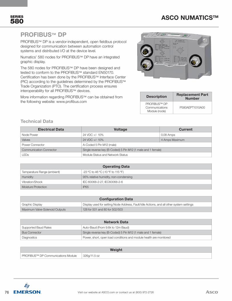
76
ASCO NUMATICS™
Visit our website at ASCO.com or contact us at (800) 972-2726
SERIES
580
PROFIBUS™ DPPROFIBUS™ DP is a vendor-independent, open fieldbus protocol designed for communication between automation control systems and distributed I/O at the device level.Numatics’ 580 nodes for PROFIBUS™ DP have an integrated graphic display. The 580 nodes for PROFIBUS™ DP have been designed and tested to conform to the PROFIBUS™ standard EN50170. Certification has been done by the PROFIBUS™ Interface Center (PIC) according to the guidelines determined by the PROFIBUS™ Trade Organization (PTO). The certification process ensures interoperability for all PROFIBUS™ devices.More information regarding PROFIBUS™ can be obtained from the following website: www.profibus.com
Technical DataElectrical Data Voltage Current
Node Power 24 VDC +/- 10% 0.08 AmpsValves 24 VDC +/- 10% 4 Amps MaximumPower Connector A-Coded 5 Pin M12 (male)Communication Connector Single reverse key (B-Coded) 5 Pin M12 (1 male and 1 female)LEDs Module Status and Network Status
Operating DataTemperature Range (ambient) -23 ºC to 46 ºC (-10 ºF to 115 ºF)Humidity 95% relative humidity, non-condensingVibration/Shock IEC 60068-2-27, IEC60068-2-6Moisture Protection IP65
Description Replacement Part Number
PROFIBUS™ DPCommunications
Module (node)P580AEPT1010A00
Configuration DataGraphic Display Display used for setting Node Address, Fault/Idle Actions, and all other system settingsMaximum Valve-Solenoid Outputs 128 for 501 and 80 for 502/503
Network DataSupported Baud Rates Auto-Baud (From 9.6k to 12m Baud)Bus Connector Single reverse key (B-Coded) 5 Pin M12 (1 male and 1 female)Diagnostics Power, short, open load conditions and module health are monitored
WeightPROFIBUS™ DP Communications Module 326g/11.5 oz

77
ASCO NUMATICS™
Visit our website at ASCO.com or contact us at (800) 972-2726
SERIES
580
PROFINET™PROFINET™ is the innovative open standard for Industrial Ethernet, development by Siemens and the Profibus™ User Organization (PNO). PROFINET™ complies to IEC 61158 and IEC 61784 standards. PROFINET™ products are certified by the PNO user organization, guaranteeing worldwide compatibility.Numatics’ 580 nodes for PROFINET™ IO (PROFINET™ RT) have an integrated graphic display. PROFINET™ is based on Ethernet and uses TCP/IP and IT standards and complements them with specific protocols and mechanisms to achieve Real Time performance. More information regarding PROFINET™ can be obtained from the following website: www.profibus.com
Technical DataElectrical Data Voltage Current
Node Power 24 VDC +/- 10% 0.11 AmpsValves 24 VDC +/- 10% 4 Amps MaximumPower Connector A-Coded 5 Pin M12 (male)Communication Connector Two D-Coded 4 Pin M12 (female)LEDs System Fault, Bus Fault and Activity Link
Operating DataTemperature Range (ambient) -23 ºC to 46 ºC (-10 ºF to 115 ºF)Humidity 95% relative humidity, non-condensingVibration/Shock IEC 60068-2-27, IEC60068-2-6Moisture Protection IP65
Description Replacement Part Number
PROFINET™Communications
Module (node)P580AEPN1010A00
Configuration DataGraphic Display Display used for setting IP Address, Subnet Mask, Fault/Idle Actions, and all other system settingsMaximum Valve-Solenoid Outputs 128 for 501 and 80 for 502/503
Network DataSupported Baud Rates 10 Mbit/100 MbitBus Connector Two D-Coded 4 Pin M12 (Female)Diagnostics Power, short, open load conditions and module health and configuration are monitoredSpecial Features Integrated web server, Integrated 2 port switch, fail-safe device settings
WeightPROFINET™ Communications Module 335g/11.8 oz

SERIES
580
78
ASCO NUMATICS™
Visit our website at ASCO.com or contact us at (800) 972-2726
580 CHARM Power and Communication Cables and Accessories Replacement Part Number
1.5 Meter Cables with M12 and Sub-D Connectors P599AF5193870010.5 Meter Cables with M12 and Sub-D Connectors P599AF519387002Valve Power Isolator P599AF516881001
NOTE: Cables are not included with node and must be ordered separately.
WeightCHARM Communications Module 320g/11.3 oz
Network DataPower and Bus Connector A-Coded 5 Pin M12 MaleDiagnostics Power, short, open load conditions are monitored
Configuration DataGraphic Display Display used for setting CHARM address and other system settingsMaximum Valve Solenoid Outputs 48 for 501/502/503
Operating DataTemperature Range -23 ºC to 46 ºC (-10 ºF to 115 ºF) Humidity 95% Relative Humidity, Non-condensingVibration/Shock IEC 60068-2-27, IEC 60068-2-6Moisture IP65
Electrical Data Voltage CurrentBus Power 6.3 V 100 mAValve Power 24 V 1.07 AmpsPower and Bus Connector A-Coded 5 Pin M12 MaleLEDs Module Status and Network Status
Technical Data
Description Replacement Part Number
580 CHARM Module (node) P580AECH1010A00
580 CHARM NodeThe 580 CHARM node provides direct connectivity of pneumatic manifolds to DeltaV with Electronic Marshalling. The node connects directly to the CHARM I/O baseplate via 2 cables which attach to CHARM column extender. The cables provide redundant communication and power to the pneumatic manifold and allow the 580 CHARM node to be directly controlled by DeltaV Explorer. The 580 CHARM node configures the same as a DO CHARM.
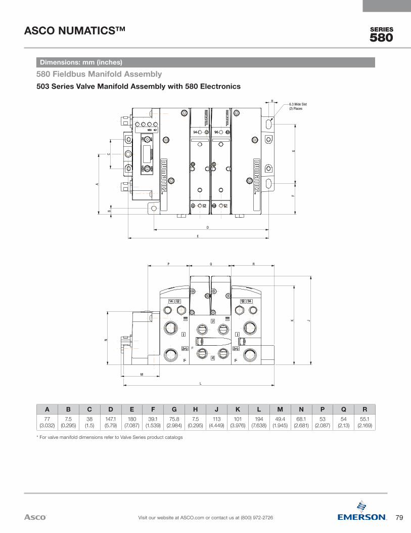
79
ASCO NUMATICS™
Visit our website at ASCO.com or contact us at (800) 972-2726
SERIES
580
E
JK
L
M
N
P RQ
H6.3 Wide Slot(2) Places
A
BC
D
FG
503 Series Valve Manifold Assembly with 580 Electronics580 Fieldbus Manifold AssemblyDimensions: mm (inches)
A B C D E F G H J K L M N P Q R77
(3.032)7.5
(0.295)38
(1.5)147.1(5.79)
180(7.087)
39.1(1.539)
75.8(2.984)
7.5(0.295)
113(4.449)
101(3.976)
194(7.638)
49.4(1.945)
68.1(2.681)
53(2.087)
54(2.13)
55.1(2.169)
* For valve manifold dimensions refer to Valve Series product catalogs

80
ASCO NUMATICS™
Visit our website at ASCO.com or contact us at (800) 972-2726
SERIES
580
ProtocolCO1 = CANopenDN1 = DeviceNetEC1 = EtherCATEP1 = EtherNet/IPPN1 = PROFINET TM
PT1 = PROFIBUSTM DPPL1 = Ethernet POWERLINKLM1 = IO-Link Class A (4 Pin)LM2 = IO-Link Class B (5 Pin)CH1 = CHARM
Connector Type1 = M12 Connector
OptionsA00 = Standard (No Options)DRM = DIN Rail Mount
Product TypeE = Electronics
RevisionA = Initial Release
Product Series580 = 580 Series Electronics
P 580 A E DN1 0 1 0 A00
How to OrderElectronics
1 Port Type 8 & G only available in Port Size 3/8 for 502 & 503 and 1/8 for 5012 501 not available with 2 stations, 502 and 503 only available with an even number of
stations and with up to 80 valve solenoids3 With 502 11mm (501) valve available, with 503 18mm (502) valve available4 501 Port Sizes 1/8, 1/4, 5/16, 8mm, 502 and 530 Port Sizes 3/8, 1/2, 10 and 12mm
Port Size1 = 1/82 = 1/4G = 5/163 = 3/84 = 1/2H = 8mmK = 10mmM = 12mm
Second Valve Series0 = No Second Valve Series1 = 5012 = 502
End Plate StyleV = Vertical
OptionsA00 = Standard (No Options)MUF = Muffler in End PlatesDRM = DIN Rail MountDWM = DIN Rail with (MUF) Muffler in End Plates14X = External Pilot Supply from Port #14D12 = (14X) External Pilot Supply from Port #14 and (MUF) Muffler in End PlatesD14 = (14X) External Pilot Supply from Port #14 and (DRM) DIN Rail MoungF06 = (14X) External Pilot Supply from Port #14, (MUF) Muffler in End Plates, and (DRM) DIN Rail Mount
Valve Station Adder0 = No Adder1 = 32+2 = 64+3 = 96+
Number of Valve StationsA = NA/33/65/97B = 2/34/66/98C = 3/35/67/99D = 4/36/68/100E = NA/37/69/101F = 6/38/70/102G = 7/39/71/103H = 8/40/72/104I = 9/41/73/105J = 10/42/74/106K = 11/43/75/107L = 12/44/76/108M = 13/45/77/109N = 14/46/78/110O = 15/47/79/111P = 16/48/80/112
Q = 17/49/81/113R = 18/50/82/114S = 19/51/83/115T = 20/52/84/116U = 21/53/85/117V = 22/54/86/118W = 23/55/87/119X = 24/56/88/120Y = 25/57/89/121Z = 26/58/90/1222 = 27/59/91/1233 = 28/60/92/1244 = 29/61/93/1255 = 30/62/94/1266 = 31/63/95/1277 = 32/64/96/128
Electronics8 = 580 Fieldbus ElectronicsD = CHARMs Electronics
Product TypeV = Valve Manifold Assembly
RevisionA = Initial Release
Product Series501 = 11mm Valve502 = 18mm Valve503 = 22mm Valve
Port Type8 = NPTFG = ISO 228/1-GK = Push-In Fittings
K 501 A V 8 D 2 0 0 V A00How to Order: Manifold Assembly
4
3
2
1
1
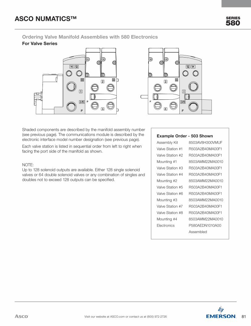
81
ASCO NUMATICS™
Visit our website at ASCO.com or contact us at (800) 972-2726
SERIES
580
Shaded components are described by the manifold assembly number (see previous page). The communications module is described by the electronic interface model number designation (see previous page).Each valve station is listed in sequential order from left to right when facing the port side of the manifold as shown.
NOTE: Up to 128 solenoid outputs are available. Either 128 single solenoid valves or 64 double solenoid valves or any combination of singles and doubles not to exceed 128 outputs can be specified.
Example Order - 503 ShownAssembly Kit 8503AV8H300VMUFValve Station #1 R503A2B40MA00F1Valve Station #2 R503A2B40MA00F1Mounting #1 8503AMM22MA0010Valve Station #3 R503A2B40MA00F1Valve Station #4 R503A2B40MA00F1Mounting #2 8503AMM22MA0010Valve Station #5 R503A2B40MA00F1Valve Station #6 R503A2B40MA00F1Mounting #3 8503AMM22MA0010Valve Station #7 R503A2B40MA00F1Valve Station #8 R503A2B40MA00F1Mounting #4 8503AMM22MA0010Electronics P580AEDN1010A00 Assembled
For Valve SeriesOrdering Valve Manifold Assemblies with 580 Electronics
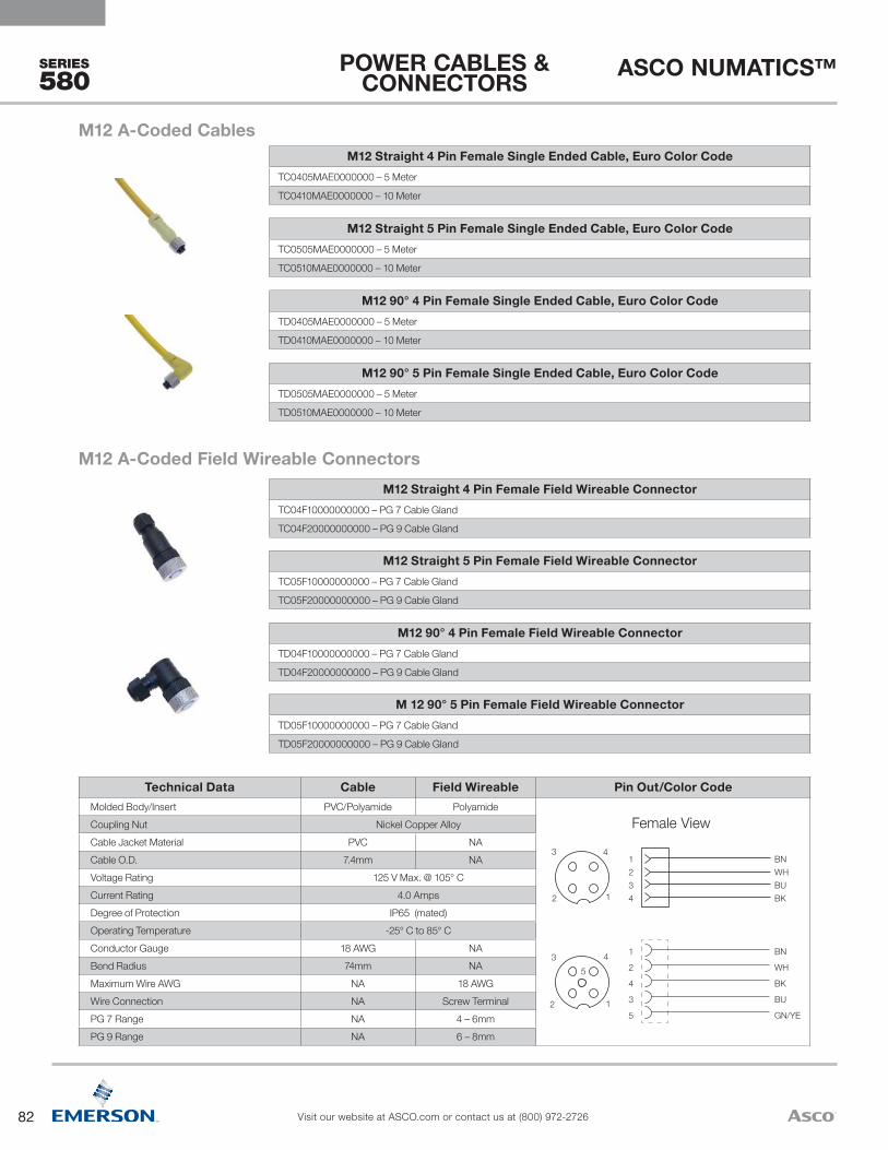
82
ASCO NUMATICS™
Visit our website at ASCO.com or contact us at (800) 972-2726
SERIES
580
BN
WH
BK
BU
GN/YE
1
2
4
3
512
3 45
1234
BNWHBUBK12
3 4
Female View
Technical Data Cable Field Wireable Pin Out/Color CodeMolded Body/Insert PVC/Polyamide PolyamideCoupling Nut Nickel Copper AlloyCable Jacket Material PVC NACable O.D. 7.4mm NAVoltage Rating 125 V Max. @ 105° CCurrent Rating 4.0 AmpsDegree of Protection IP65 (mated)Operating Temperature -25° C to 85° CConductor Gauge 18 AWG NABend Radius 74mm NAMaximum Wire AWG NA 18 AWGWire Connection NA Screw TerminalPG 7 Range NA 4 – 6mmPG 9 Range NA 6 – 8mm
M 12 90° 5 Pin Female Field Wireable ConnectorTD05F10000000000 – PG 7 Cable Gland
TD05F20000000000 – PG 9 Cable Gland
M12 90° 4 Pin Female Field Wireable ConnectorTD04F10000000000 – PG 7 Cable Gland
TD04F20000000000 – PG 9 Cable Gland
M12 Straight 5 Pin Female Field Wireable ConnectorTC05F10000000000 – PG 7 Cable Gland
TC05F20000000000 – PG 9 Cable Gland
M12 Straight 4 Pin Female Field Wireable ConnectorTC04F10000000000 – PG 7 Cable Gland
TC04F20000000000 – PG 9 Cable Gland
M12 A-Coded Field Wireable Connectors
M12 90° 5 Pin Female Single Ended Cable, Euro Color CodeTD0505MAE0000000 – 5 Meter
TD0510MAE0000000 – 10 Meter
M12 90° 4 Pin Female Single Ended Cable, Euro Color CodeTD0405MAE0000000 – 5 Meter
TD0410MAE0000000 – 10 Meter
M12 Straight 5 Pin Female Single Ended Cable, Euro Color CodeTC0505MAE0000000 – 5 Meter
TC0510MAE0000000 – 10 Meter
M12 Straight 4 Pin Female Single Ended Cable, Euro Color CodeTC0405MAE0000000 – 5 Meter
TC0410MAE0000000 – 10 Meter
M12 A-Coded Cables
POWER CABLES & CONNECTORS
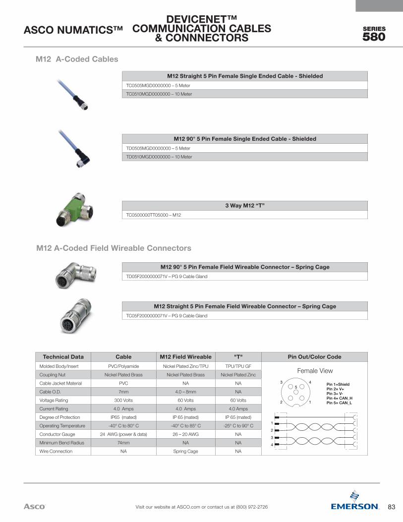
83
ASCO NUMATICS™
Visit our website at ASCO.com or contact us at (800) 972-2726
SERIES
580
Technical Data Cable M12 Field Wireable "T" Pin Out/Color CodeMolded Body/Insert PVC/Polyamide Nickel Plated Zinc/TPU TPU/TPU GF
Coupling Nut Nickel Plated Brass Nickel Plated Brass Nickel Plated Zinc
Cable Jacket Material PVC NA NA
Cable O.D. 7mm 4.0 – 8mm NA
Voltage Rating 300 Volts 60 Volts 60 Volts
Current Rating 4.0 Amps 4.0 Amps 4.0 Amps
Degree of Protection IP65 (mated) IP 65 (mated) IP 65 (mated)
Operating Temperature -40° C to 80° C -40° C to 85° C -25° C to 90° C
Conductor Gauge 24 AWG (power & data) 26 – 20 AWG NA
Minimum Bend Radius 74mm NA NA
Wire Connection NA Spring Cage NA
1
2
3
4
Pin 1=ShieldPin 2= V+Pin 3= V-Pin 4= CAN_HPin 5= CAN_L
35
4
2 1
Female View
M12 Straight 5 Pin Female Field Wireable Connector – Spring CageTC05F2000000071V – PG 9 Cable Gland
M12 90° 5 Pin Female Field Wireable Connector – Spring CageTD05F2000000071V – PG 9 Cable Gland
M12 A-Coded Field Wireable Connectors
3 Way M12 “T”TC0500000TT05000 – M12
M12 90° 5 Pin Female Single Ended Cable - ShieldedTD0505MGD0000000 – 5 Meter
TD0510MGD0000000 – 10 Meter
M12 Straight 5 Pin Female Single Ended Cable - ShieldedTC0505MGD0000000 – 5 Meter
TC0510MGD0000000 – 10 Meter
M12 A-Coded Cables
DEVICENET™COMMUNICATION CABLES
& CONNNECTORS
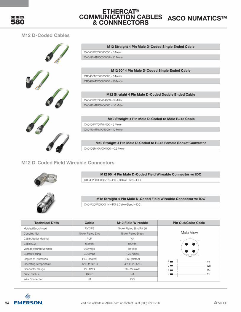
84
ASCO NUMATICS™
Visit our website at ASCO.com or contact us at (800) 972-2726
SERIES
580
1
2
3
4
YE
WH
OG
BU
34
21
Male View
Technical Data Cable M12 Field Wireable Pin Out/Color CodeMolded Body/Insert PVC/PE Nickel Plated Zinc/PA 66
Coupling Nut Nickel Plated Zinc Nickel Plated Brass
Cable Jacket Material PUR NA
Cable O.D. 6.5mm 8.0mm
Voltage Rating (Nominal) 300 Volts 60 Volts
Current Rating 2.0 Amps 1.75 Amps
Degree of Protection IP65 (mated) IP65 (mated)
Operating Temperature -5° C to 50° C -40° C to 85° C
Conductor Gauge 22 AWG 26 – 22 AWG
Bend Radius 46mm NA
Wire Connection NA IDC
M12 Straight 4 Pin Male D-Coded Field Wireable Connector w/ IDCQA04F200R000071N – PG 9 Cable Gland – IDC
M12 90° 4 Pin Male D-Coded Field Wireable Connector w/ IDCQB04F200R000071N – PG 9 Cable Gland – IDC
M12 D-Coded Field Wireable Connectors
M12 Straight 4 Pin Male D-Coded to RJ45 Female Socket ConvertorQA04D2MK0VC04000 – 0.2 Meter
M12 Straight 4 Pin Male D-Coded to Male RJ45 CableQA0405MT0VA04000 – 5 Meter
QA0410MT0VA04000 – 10 Meter
M12 Straight 4 Pin Male D-Coded Double Ended CableQA0405MT0QA04000 – 5 Meter
QA0410MT0QA04000 – 10 Meter
M12 90° 4 Pin Male D-Coded Single Ended CableQB0405MT00000000 – 5 Meter
QB0410MT00000000 – 10 Meter
M12 Straight 4 Pin Male D-Coded Single Ended CableQA0405MT00000000 – 5 Meter
QA0410MT00000000 – 10 Meter
M12 D-Coded Cables
ETHERCAT® COMMUNICATION CABLES
& CONNNECTORS

85
ASCO NUMATICS™
Visit our website at ASCO.com or contact us at (800) 972-2726
SERIES
580
Technical Data Cable M12 Field Wireable Pin Out/Color CodeMolded Body/Insert PUR/Polyamide Nickel Plated Zinc/PA 66
Coupling Nut Nickel Plated Brass Nickel Plated Brass
Cable Jacket Material PUR NA
Cable O.D. 5.6mm 4.0 – 8mm
Voltage Rating (Nominal) 300 Volts 60 Volts
Current Rating 2.0 Amps 1.75 Amps
Degree of Protection IP65 (mated) IP 65 (mated)
Operating Temperature -40° C to 75° C -40° C to 85° C
Conductor Gauge 24 AWG IDC 26 – 22 AWG
Bend Radius 61mm NA
Wire Connection NA IDC
1
2
3
4
WH/OG
OG
WH/GN
GN
34
21
Male View
M12 Straight 4 Pin Male D-Coded Field Wireable Connector w/ IDCQA04F2000000071N – PG 9 Cable Gland – IDC
M12 90° 4 Pin Male D-Coded Field Wireable Connector w/ IDCQB04F2000000071N – PG 9 Cable Gland – IDC
M12 D-Coded Field Wireable Connectors
M12 Straight 4 Pin Male D-Coded to RJ45 Female Socket ConvertorQA04D2MK0VC04000 – 0.2 Meter
M12 90° 4 Pin Male D-Coded Single Ended CableQB0405MK00000000 – 5 Meter
QB0410MK00000000 – 10 Meter
M12 Straight 4 Pin Male D-Coded Single Ended CableQA0405MK00000000 – 5 Meter
QA0410MK00000000 – 10 Meter
M12 Straight 4 Pin Male D-Coded to Male RJ45 CableQA0405MK0VA04000 – 5 Meter
QA0410MK0VA04000 – 10 Meter
M12 D-Coded Cables
ETHERNET/IP™COMMUNICATION CABLES
& CONNECTORS

86
ASCO NUMATICS™
Visit our website at ASCO.com or contact us at (800) 972-2726
SERIES
580
Female View
Technical Data Cable M12 Field Wireable Pin Out/Color CodeMolded Body/Insert TPU Polyamide
Coupling Nut Nickel Plated Zinc Nickel Plated Zinc
Cable Jacket Material PUR NA
Cable O.D. 5mm Accepts 3.0 – 6.5mm
Voltage Rating 60 Volts 125 Volts
Current Rating 4.0 Amps 4.0 Amps
Degree of Protection IP65 (mated) IP65 (mated)
Operating Temperature -25° C to 90° C (-13° F to 194° F)
-20° C to 100° C (-4° F to 212° F)
Conductor Gauge 22 AWG 18 – 24 AWG
Minimum Bend Radius 50mm NA
Wire Connection NA Screw Terminal
* See page 107 for M12 4 Pin field wireable connectors if the selected IO-Link® Master does not accept 5 Pin field wireable connectors. Maximum IO-Link® cable length is 20m.
M12 90° 5 Pin Male Field Wireable Connector – Screw TerminalTB05F10000000000 – PG 7 Cable Gland
M12 Straight 5 Pin Male Field Wireable Connector – Screw TerminalTA05F10000000000 – PG 7 Cable Gland
M12 Class A & B Compatible Field Wireable Connectors* * See page 107 for M12 4 Pin cables if the selected IO-Link® Master does not accept 5 Pin cables. Maximum IO-Link® cable length is 20m.
M12 90° 5 Pin Female to Male Double Ended Cable - UnshieldedTD0505MIETA0571P – 5 Meter
TD0510MIETA0571P – 10 Meter
M12 90° 5 Pin Female Single Ended Cable - UnshieldedTD0505MIE000071P – 5 Meter
TD0510MIE000071P – 10 Meter
M12 Straight 5 Pin Female to Male Double Ended Cable - UnshieldedTC0505MIETA0571P – 5 Meter
TC0510MIETA0571P – 10 Meter
M12 Straight 5 Pin Female Single Ended Cable - UnshieldedTC0505MIE000071P – 5 Meter
TC0510MIE000071P – 10 Meter
M12 Class A & B Compatible Cables*
IO-LINK® COMMUNICATION CLASS A & B CABLES
& CONNNECTORS

87
ASCO NUMATICS™
Visit our website at ASCO.com or contact us at (800) 972-2726
SERIES
580
1
2
3
4
5
GN
RD
34
5
21
Male View
Technical Data Cable Field Wireable "T" Pin Out/Color CodeMolded Body PUR Nickel Plated Zinc/Brass Aluminum
Insert Polyamide TPU/PVC Nylon
Coupling Nut Nickel Plated Brass Nickel Plated Brass/Stainless Steel Nickel Plated Brass
Cable Jacket Material PVC NA NA
Cable O.D. 8.5mm 4.0 – 8.0mm/3.0 – 6.5mm NA
Voltage Rating 300 Volts 60 Volts 250 Volts
Current Rating 4.0 Amps 4.0 Amps 4.0 Amps
Degree of Protection IP65 (mated) IP65 (mated) IP65 (mated)
Operating Temperature -40° C to 80° C -40° C to 85° C -40° C to 80° C
Conductor Gauge 22 AWG 26 – 20 AWG/24 – 18 AWG NA
Minimum Bend Radius 74mm NA NA
Wire Connection NA IDC/Screw Terminal NA
M12 Bus “T”RA050000PRT05000
M12 Straight 5 Pin Terminating ResistorRA05TR0000000000 – MALE
M12 Straight 5 Pin Male & Female Field Wireable ConnectorRA05F200P0000000 – PG7 Cable Gland – MALE
RC05F200P0000000 – PG7 Cable Gland – FEMALE
M12 90° 5 Pin Male & Female Field Wireable Connector w/ IDCRB05F200P000071V – PG9 Cable Gland – IDC MALE
RD05F200P000071V – PG9 Cable Gland – IDC FEMALE
M12 B-Coded (Reverse Key) Field Wireable Connectors
M12 90° 5 Pin Male & Female Single Ended CableRB0505MHP0000000 – 5 Meter – MALE
RB0510MHP0000000 – 10 Meter – MALE
RD0505MHP0000000 – 5 Meter – FEMALE
RD0510MHP0000000 – 10 Meter – FEMALE
M12 Straight 5 Pin Male – to – Female Double Ended CablesRC0505MHPRA05000 – 5 Meter
RC0510MHPRA05000 – 10 Meter
M12 Straight 5 Pin Male & Female Single Ended CablesRA0505MHP0000000 – 5 Meter – MALE
RA0510MHP0000000 – 10 Meter – MALE
RC0505MHP0000000 – 5 Meter – FEMALE
RC0510MHP0000000 – 10 Meter – FEMALE
M12 B-Coded (Reverse Key) Cables
PROFIBUS™ DPCOMMUNICATION CABLES
& CONNECTORS

88
ASCO NUMATICS™
Visit our website at ASCO.com or contact us at (800) 972-2726
SERIES
580
1
2
3
4
YE
WH
OG
BU
34
21
Male View
Technical Data Cable M12 Field Wireable Pin Out/Color CodeMolded Body/Insert PUR/PUR or PE Nickel Plated Zinc/PA 66
Coupling Nut Nickel Plated Zinc and Brass Nickel Plated Brass
Cable Jacket Material PVC NA
Cable O.D. 6.5mm/74mm 4.0 – 8.0mm
Voltage Rating (Nominal) 42 Volts 60 Volts
Current Rating 1.5 Amps 1.75 Amps
Degree of Protection IP65 (mated) IP65 (mated)
Operating Temperature -25° C to 60° -40° C to 85° C
Conductor Gauge 24 & 22 AWG 26 – 22 AWG
Bend Radius 19.5mm NA
Wire Connection NA IDC
M12 Straight 4 Pin Male D-Coded Field Wireable Connector w/ IDCQA04F200R000071N – PG 9 Cable Gland – IDC
M12 90° 4 Pin Male D-Coded Field Wireable Connector w/ IDCQB04F200R000071N – PG 9 Cable Gland – IDC
M12 D-Coded Field Wireable Connectors
M12 Straight 4 Pin Male D-Coded to RJ45 Female Socket ConvertorQA04D2MK0VC04000 – 0.2 Meter
M12 Straight 4 Pin Male D-Coded to Male RJ45 CableQA0405MR0VA04000 – 5 Meter
QA0410MR0VA04000 – 10 Meter
M12 Straight 4 Pin Male D-Coded Double Ended CableQA0405MR0QA04000 – 5 Meter
QA0410MR0QA04000 – 10 Meter
M12 90° 4 Pin Male D-Coded Single Ended CableQB0405MR00000000 – 5 Meter
QB0410MR00000000 – 10 Meter
M12 Straight 4 Pin Male D-Coded Single Ended CableQA0405MR00000000 – 5 Meter
QA0410MR00000000 – 10 Meter
M12 D-Coded Cables
PROFINET™COMMUNICATION CABLES
& CONNNECTORS

ASCO Headquarters (USA) | Tel (1) 800.972.2726 | www.asco.com | e-mail: [email protected]
Netherlands (31) 33-277-7911Singapore (65) 6556-1100South Korea (82) 2-3483-1570Spain (34) 942-87-6100United Kingdom (44) 1695-713600
France (33) 2-37-24-42-24Germany (49) 7237-9960India (91) 44-39197300Italy (39) 02-356931Japan (81) 798-65-6361Mexico (52) 55-5809-5640
Australia (61) 2-9-451-7077Brazil (55) 11-4208-1700Canada (1) 519-758-2700China (86) 21-3395-0000Czech Republic (420) 235-090-061Dubai - UAE (971) 4 811 8200
Global Contacts
07/18 — V7728