imp notes to print
DESCRIPTION
basicsTRANSCRIPT
Guidelines to be followed for making a column layout
Today, we will discuss something very general. Inspite of knowing these general thumb rules, Civil Engineers still end up making disastrous mistakes which would not only cost them but also cost the people living in the building designed by these engineers.
Earlier, I wrote an article describing one of my projects where structural designing was executed on site (which was extremely pathetic) even before Architectural design was done. (Check out: Consequences of Wrong Structural Design | Live Project example)In this article, we will go through the essential thumb rules to be followed for giving a column layout. Ofcourse RCC columns have to be designed in accordance to the total load on the columns but apart from that it is essential for every Civil engineer and Architect to remember a few thumb rules so that they are prevented from making mistakes.
Three thumb rules to be followed are as follows:
1. Size of the Columns2. Distance between Columns3. Alignment of columns
Thumb rule no.1
Size of the columns
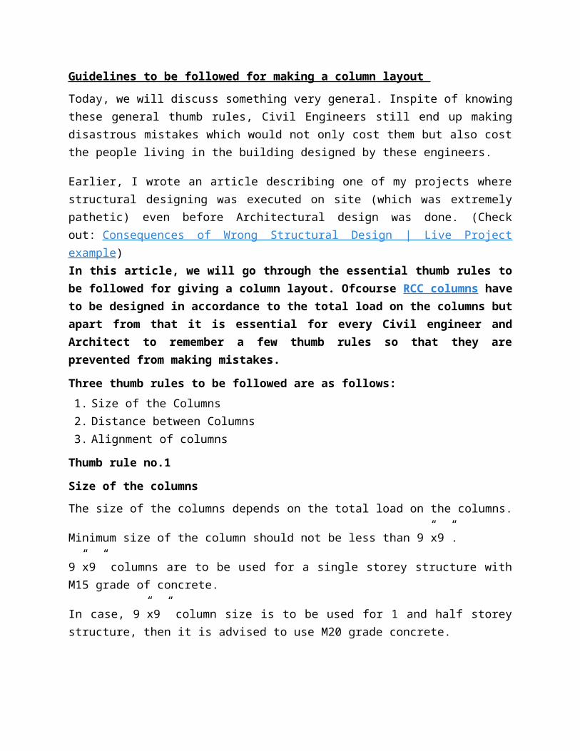
The size of the columns depends on the total load on the columns.
Minimum size of the column should not be less than 9”x9”.
9”x9” columns are to be used for a single storey structure with M15 grade of concrete.
In case, 9”x9” column size is to be used for 1 and half storey structure, then it is advised to use M20 grade concrete.
A safe and structurally sound column size for a 1 and half storey structure should not be less than 12”x9” using M15 grade concrete. This should be in your most preferred and practical options list.
Thumb rule no.2
Distance between the columns
Try to maintain equal distance between the centres of two columns. Always plan a column layout on a grid.
The distance between two columns of size 9”x9” should not be more than 4m centre to centre of column.
If larger barrier free distances are required then going for larger column size is to be used.

The size of the columns increase because of two factors:
1. Increase in the distance between two columns (This increases the dimensions of the columns as well the depth of the beam.)
2. Height of the building (Increase in the number of floors is directly proportional to the dimensions of the columns.
Thumb rule no.3
Alignment of Columns
A rectangular grid is to be made for placing the columns. This helps in avoiding mistakes and placing in columns can be done in the right way.
The columns can preferably be arranged in two different fashions:
1. In a straight line with the help of a grid2. In a circular fashion for circular buildings.
Zigzag arrangement of columns is an absolutely wrong way of working out Structural design. It should be remembered that when columns are erected, beams are laid connecting the columns.
The Zigzag column placement causes three major issues:
1. Unbalanced load transfer2. Problems in wall construction3. Problems in laying beams
If these three thumb rules are followed by Civil Engineering and Architecture students, implementation of wrong Structural design can be prevented.In the next article, I will explain these three thumb rules with the help of an example “Column Layout for a Residence“.
Also read:
Introduction to design of RCC StructuresBuilding Design Guide which includes design of:1. RCC columns2. RCC beams3. Foundations4. Staircase
Column Layout for a residence using the Thumb rules| Building ConstructionIn my earlier article, we discussed three important thumb rules that are to be followed while making a column layout for any building. They are as follows:1. Size of the Columns 2. Distance between the columns 3. Alignment of Columns
In this article, we will see an example of a residence of which column layout is done keeping the above three thumb rules in mind.

Column Layout for a residence
The residential villa comprises of 1 and half floors. Initially, the column size 9″x12″ had been used with the use of M15 grade of concrete. The builder wanted to save on his budget by making the columns smaller in size. That is why, the columns in the Floor plans below are 9″x9″ in size but the Engineer made sure that M20 grade of concrete would be used for Columns.
Column Layout for a Ground Floor

Column Layout for First Floor
Thumb rule no1:
Size of the Columns
The size of the columns are 9″x9″ with the use of M20 grade of concrete.
Thumb rule no.2:
Distance between the columns:
The distance between the columns does not exceed 4.5m.
Thumb rule no.3:

Alignment of Columns
The Columns have been arranged on a iron grid pattern. So there is absolutely no question of zigzag walls and zigzag beams which reducing complications in the structure.
Fly ash Bricks | An alternative Building Material
Fly ash bricks are masonry units that are used in the construction of buildings. They are considered to be a part of good and affordable building materials. They contain Class C fly ash and water.
Fly ash bricks are made by compressing Class C fly ash and water at 4000psi and then curing is carried on for 24 hours at a temperature of 66 degrees Celsius steam bath. Air entrainment agent is used to toughen the bricks.
Fly ash Bricks
Since the concentration of calcium oxide is very high in class C fly ash, the brick is described as self cementing.
It is considered to be a good alternative to traditional mud bricks since the method of manufacture of fly ash is energy efficient that is it helps save energy, brings about reduction of mercury pollution and plus it is cost effective.
Raw materials used for the manufacture of Fly ash Bricks:

Fly ash – which is the primary ingredient Sand or Stone dust – as fine aggregate Lime – source of calcium carbonate which results in the bricks being called “Self-
cementing bricks”. Gypsum – to enhance the fineness of the shape of the bricks Cement – to increase bonding and strength
General Characteristics of Fly ash Bricks
The standard size of the brick is 230x110x70 The bricks are manufactured and tested as per IS 12894-2002 Fly ash bricks are sound, compact and uniform in shape, size and colour. Smooth
rectangular faces of the bricks are accompanied with sharp and square corners.
Fly ash Bricks | Available in various colours and shapes. The above picture shows the bricks in dark peach colour with three holes on it. These holes are used for grouting. The mortar is poured
into these holes for proper bonding in between the bricks.
They are free from visible cracks, warpage, flaws and organic matter. Compressive strength: 7.5N/mm2 on an average Water absorption: <8%
Advantages of Fly ash Bricks
They have high strength which is their primary benefit to be used for construction. Due to uniform size and thickness of joints, plaster consumption is minimized compared to
clay bricks, thereby saving cement to the extent of 25% to 30%. Due to lesser water absorption, there is no dampness in walls.

Gypsum plaster, Plaster of Paris can be applied directly without the basecoat of plaster. Wastage is very less as compared to clay brick. The bonding between the bricks is excellent since there is high concentration of calcium
oxide in it.
Uses of Fly ash Bricks
Fly ash bricks are used for the construction of various types of buildings such as: Factories Warehouses Power plants Homes High rise structures
Basically, they are used in every kind of construction that can be possibly executed with the help of traditional bricks.
Design of Overhead Water Tank | Design of RCC Structures
As per NBC (National Building Code, 2005) standards,
Water required per person per day = 150 litresDrinking water = 4litres per person per day
Calculation for an overhead water tank for a 3 BHK Villa:
Let us assume the average family size = 5 persons in the house
Water required for daily chores per person per day as per NBC norms;
150 x 5 = 750 litres
Drinking water required:
4 x 5 = 20 litres
Total quantity of water required = 750+20 = 770 litres
Volume of water = 770/1000 = 0.77 cubic metres
Dimensions for the overhead water tank:
Length = 1.2m
Breadth = 0.6m
Depth = 1.1m

Total Volume = 1.2×0.6×1.1 = 0.792 cubic metres
Load Calculations | Types of Loads
Students find it difficult to understand the concept of loads although it is a very simple concept. We are
going to write a series of articles on “Load Calculations” and help you all in understanding different types of
loads that are to be considered for structural designing and also how to calculate them.
In this article, we will discuss different types of loads with examples.
In our next article, we will cover the following points: Design principle assumption and notation assumed
Design Constant
Assumptions regarding Design
Loads on Beams
Loads on slabs
An object is subject to mainly two types of forces:1. Live loads
2. Dead loads
Basically, an object subject to any type of force which could be gravitational force (weight), pressure or
anything affects the object is called a load.
This concept is used in Mechanical and structural engineering. Let’s take in terms of Structural Engineering.
Whenever a structure is designed, these concepts are taken into consideration because real world objects
are analyzed in order to design the structure. This is very important in terms of structural stability.
What are “Dead loads”?
As the name itself suggests, dead loads could be termed as self weight of the non-living objects. It could be
the weight of the materials, equipments or any other components in the structure that will remain
permanent throughout the life of the structure.
Dead load has to be considered in order to make the structural design accordingly. Dead loads vary from
structure to structure. Every building is unique and has different considerations.
An additional load is considered in case additional forces build up in a structure in case of settlement or due
to secondary effects of pre-stress construction or due to shrinkage of concrete.
For the calculations of dead loads, we could also consider,
Columns
Beams
Footings
Lintels
Furniture
Machinery and other equipment
Walls
Floors

Roofs
Ceilings
Stairways
Built-in partitions
Finishes (POP – Plaster of Paris)
Cladding (Use of various materials which increase the self weight of the structure) etc.
Basically, all the permanent loads are to be considered.
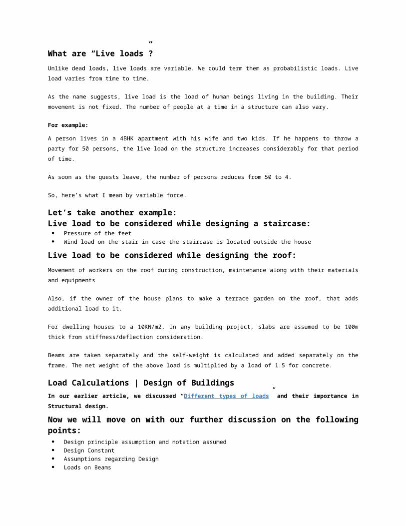
What are “Live loads”?
Unlike dead loads, live loads are variable. We could term them as probabilistic loads. Live load varies from
time to time.
As the name suggests, live load is the load of human beings living in the building. Their movement is not
fixed. The number of people at a time in a structure can also vary.
For example:
A person lives in a 4BHK apartment with his wife and two kids. If he happens to throw a party for 50 persons,
the live load on the structure increases considerably for that period of time.
As soon as the guests leave, the number of persons reduces from 50 to 4.
So, here’s what I mean by variable force.
Let’s take another example:Live load to be considered while designing a staircase: Pressure of the feet
Wind load on the stair in case the staircase is located outside the house
Live load to be considered while designing the roof:
Movement of workers on the roof during construction, maintenance along with their materials and
equipments
Also, if the owner of the house plans to make a terrace garden on the roof, that adds additional load to it.
For dwelling houses to a 10KN/m2. In any building project, slabs are assumed to be 100m thick from
stiffness/deflection consideration.
Beams are taken separately and the self-weight is calculated and added separately on the frame. The net
weight of the above load is multiplied by a load of 1.5 for concrete.
Load Calculations | Design of Buildings
In our earlier article, we discussed “Different types of loads” and their importance in Structural
design.
Now we will move on with our further discussion on the following points: Design principle assumption and notation assumed

Design Constant
Assumptions regarding Design
Loads on Beams
Loads on slabs
Design principle assumption and notation assumed:
The notations adopted throughout are same as given in IS:456:2000
Density of material used in accordance with reference to IS:857-1987s
Sr.no Material Density
1 Plain concrete 24 KN/m3
2 Reinforced cement concrete 25 KN/m3
3 Flooring material (cement mortar)
1.00 KN/m3
4 Brick masonry 19 KN/m3
Design constant
Using M20 and Fe415 grade of concrete and steel respectively for columns and footings
Therefore:
Fck – i. e. Characteristic strength for M15 – 15 N/mm2
Fck – i. e. Characteristic strength for M15 – 15 N/mm2
Fck – i. e. Characteristic strength for M20 – 20 N/mm2
Fy – i. e. Characteristic strength for steel – 415 N/mm2
Assumption regarding Design1. Slab is assumed to be continuous over interior support and partial fixed on the edge, due to monolithic
construction of walls over it.
2. Beams are assumed to be continuous over interior support and they frame in to the column at the
ends.
Load on Beams
Description of load of slab on beam
The load of slab is dispersed on to the supporting beams in accordance with clause 23.5 of IS:456-1978,
which states that the load on beams supporting solid spans, spacing in two directions at right angles and
supporting uniformly distributed loads.
Self weight of beams
This load acts on the beams as a UDL, this is calculated after assuming the suitable cross section (by
stiffness/deflection consideration) of the beam.
Load due to brick masonry wall
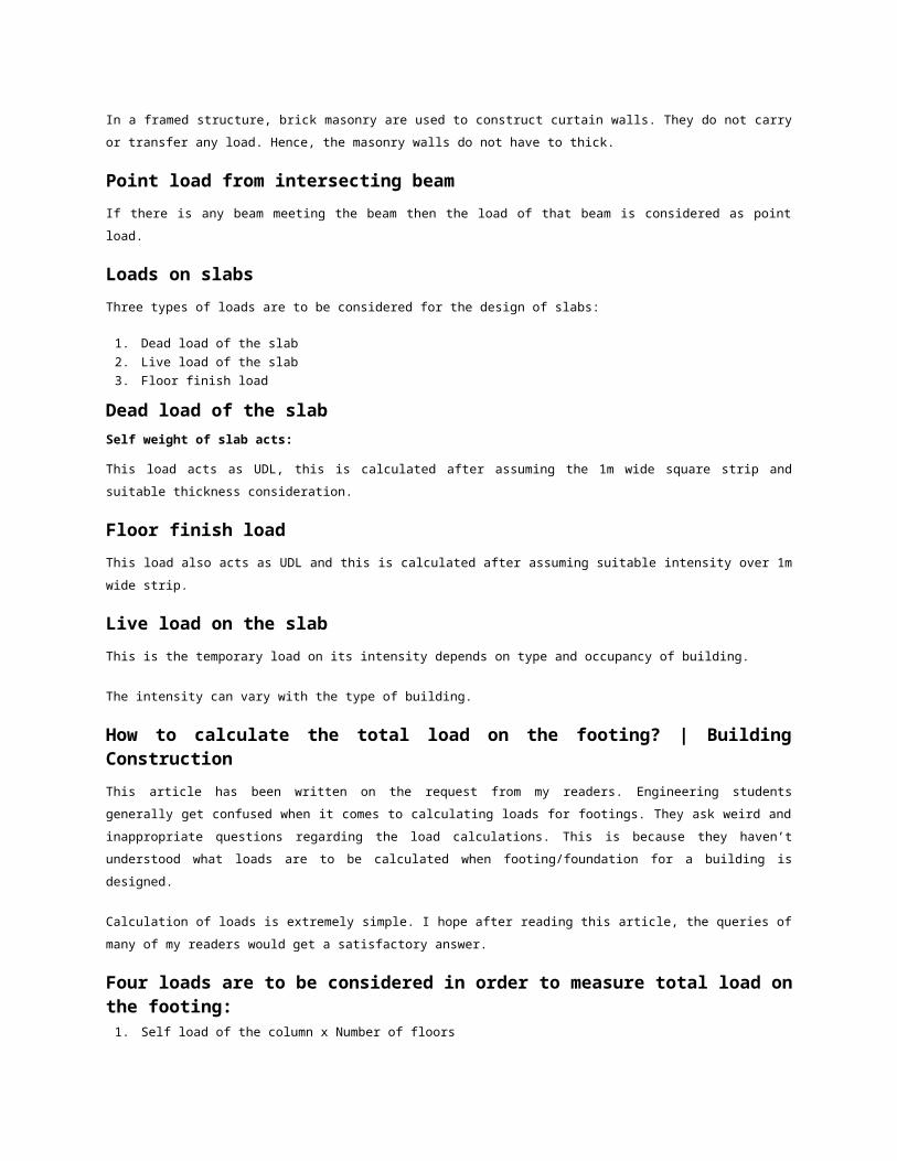
In a framed structure, brick masonry are used to construct curtain walls. They do not carry or transfer any
load. Hence, the masonry walls do not have to thick.
Point load from intersecting beam
If there is any beam meeting the beam then the load of that beam is considered as point load.
Loads on slabs
Three types of loads are to be considered for the design of slabs:
1. Dead load of the slab
2. Live load of the slab
3. Floor finish load
Dead load of the slab
Self weight of slab acts:
This load acts as UDL, this is calculated after assuming the 1m wide square strip and suitable thickness
consideration.
Floor finish load
This load also acts as UDL and this is calculated after assuming suitable intensity over 1m wide strip.
Live load on the slab
This is the temporary load on its intensity depends on type and occupancy of building.
The intensity can vary with the type of building.
How to calculate the total load on the footing? | Building Construction
This article has been written on the request from my readers. Engineering students generally get confused
when it comes to calculating loads for footings. They ask weird and inappropriate questions regarding the
load calculations. This is because they haven’t understood what loads are to be calculated when
footing/foundation for a building is designed.
Calculation of loads is extremely simple. I hope after reading this article, the queries of many of my readers
would get a satisfactory answer.
Four loads are to be considered in order to measure total load on the footing:1. Self load of the column x Number of floors
2. Self load of beams x Number of floors
3. Load of walls coming onto the column
4. Total Load on slab (Dead load + Live load)If you get well versed with load calculations, then calculating the size of the footing and following the procedure for foundation design wouldn’t be a problem.
How to design a retaining wall? | RCC Design

Main parts of Retaining WallThe stem and base are the main parts of a cantilever type of retaining wall. The toe is the front portion and heel is the back portion. The stem is supported at the base and the wall tapers towards the top.Wall DimensionsGenerally the height of the wall known and approximate dimensions are required to be assumed.The length of the base is between 0.4 to 0.7 times the height of the wall. Toe to base ratio is 1:4. The thickness of the base slab shall be assumed to be little more than the thickness of the stem at the bottom. The minimum thickness of the stem shall be 200mm for construction purposes.
Earth pressure on wallA length of one metre of the wall is considered for design.Earth levelled up to the top of wall:
From Rankine’s theory of earth pressure
where,P = total pressure on wall acting at H/3 from the baseH = total height in metresW = weight or density of earth in kN/m3
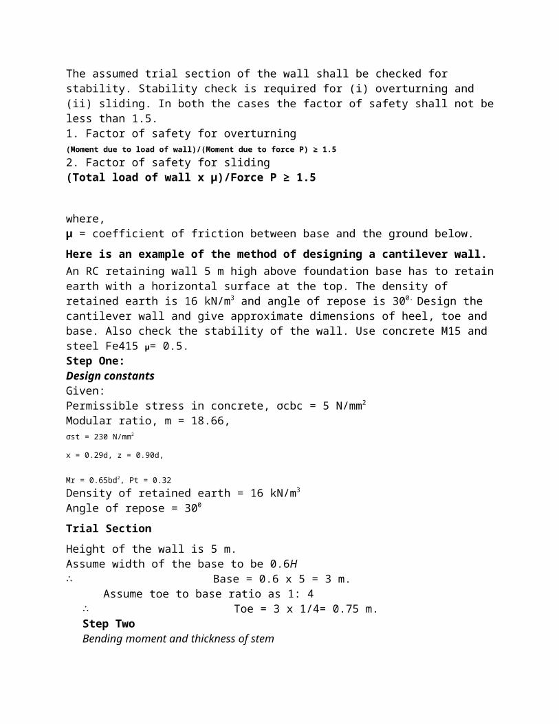
Φ = angle of repose of earthStability of retaining wallThe assumed trial section of the wall shall be checked for stability. Stability check is required for (i) overturning and (ii) sliding. In both the cases the factor of safety shall not be less than 1.5.1. Factor of safety for overturning(Moment due to load of wall)/(Moment due to force P) ≥ 1.5
2. Factor of safety for sliding(Total load of wall x μ)/Force P ≥ 1.5
where, μ = coefficient of friction between base and the ground below.
Here is an example of the method of designing a cantilever wall.
An RC retaining wall 5 m high above foundation base has to retain earth with a horizontal surface at the top. The density of retained earth is 16 kN/m3 and angle of repose is 300. Design the cantilever wall and give approximate dimensions of heel, toe and base. Also check the stability of the wall. Use concrete M15 and steel Fe415 μ= 0.5.Step One:Design constantsGiven:Permissible stress in concrete, σcbc = 5 N/mm2
Modular ratio, m = 18.66,σst = 230 N/mm2
x = 0.29d, z = 0.90d,
Mr = 0.65bd2, Pt = 0.32
Density of retained earth = 16 kN/m3
Angle of repose = 300
Trial Section
Height of the wall is 5 m.Assume width of the base to be 0.6H∴ Base = 0.6 x 5 = 3 m. Assume toe to base ratio as 1: 4∴ Toe = 3 x 1/4= 0.75 m.

Step TwoBending moment and thickness of stemConsider 1 m length of stem.Horizontal pressure of earth on stem, (P)
Bending moment at the base of stem, i.e., 5 m below the topM = P x H/3 = 67 x 5/3
= 111.66kN-m or 112 kN-m
The value of the bending moment goes on reducing towards the top and becomes zero at the top.Bending moment at 2.5 m below the top,
Step threeThickness of stem (at the base)Equating Mr to M,
Equating to
0.65bd2 = 112 x 106
0.65 x 1000 x d2 = 112 x 106
d = 415.09mm = 415mm
Assuming 20 mm Φ bars and 25 mm cover,
D = 415 + 20/2 + 25 = 450mm
Provide 20 mm thickness at the topThickness available at 2.5 m below the top0.65 x 1000 x d2
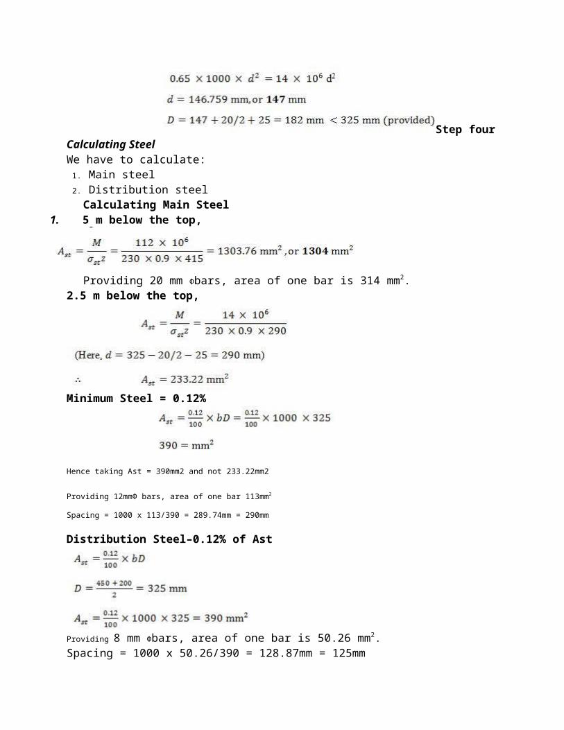
d = 146.759mm = 147mm
Required thickness at 2.5 m below the top

Step fourCalculating SteelWe have to calculate:
1. Main steel2. Distribution steel
Calculating Main Steel1. 5 m below the top,
Providing 20 mm Φbars, area of one bar is 314 mm2.2.5 m below the top,
Minimum Steel = 0.12%
Hence taking Ast = 390mm2 and not 233.22mm2
Providing 12mmΦ bars, area of one bar 113mm2
Spacing = 1000 x 113/390 = 289.74mm = 290mm
Distribution Steel–0.12% of Ast
Providing 8 mm Φbars, area of one bar is 50.26 mm2.Spacing = 1000 x 50.26/390 = 128.87mm = 125mm Step Five
Check for shearThe formula for maximum shear at the base is given by,
V = 67kN
For concrete M15 and Pt = 0.31, Tc= 0.22 N/mm2
Since Tc > Tv, no shear reinforcement is required.Step SixThe formula for Development length is given by,
(a) At the base of stem.For 20 mm Φbars,
(b) At 2.5 m below the top,For 12 mm Φbars;Ld = 12 x 230/4 x 0.84 = 1369mm = 1370mm
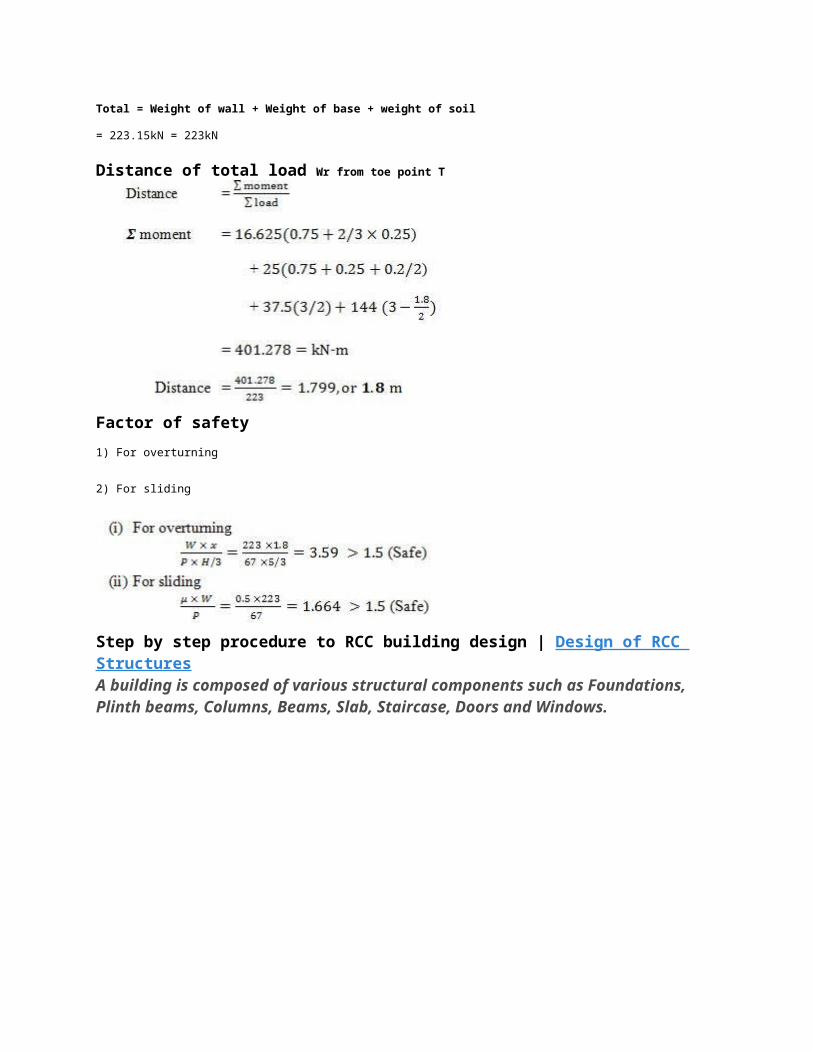
Step SevenCheck for StabilityAssume thickness of base as 500mmTotal vertical loadsThe calculation of vertical loads include weight of wall, weight of base and weight of soil.Weight of wall
Weight of base
3 – 0.5 x 3 x 25 = 37.50kN
Weight of soil
4 – 1.8 x 5 x 16 = 144 kN
Total = Weight of wall + Weight of base + weight of soil
= 223.15kN = 223kN

Distance of total load Wr from toe point T
Factor of safety
1) For overturning
2) For sliding
Step by step procedure to RCC building design | Design of RCC StructuresA building is composed of various structural components such as Foundations, Plinth beams, Columns, Beams, Slab, Staircase, Doors and Windows.
RCC Building Design
Design of Foundation | RCC Building Design
Foundation design is the structural component from where the RCC design is initiated. The foundation design
guide discussed earlier includes in detail the design procedure for isolated column footing. Column footing is
the most commonly used type of foundation. It serves a variety of different buildings.
Design of Foundation – the most commonly used foundation is Column footing.
Calculation of loads in Foundation Design Calculation of loads is very important for the purpose of
structural design. This article outlines the thumb rules for the calculation of various loads in foundation
design.
Types of Foundations This is a generic article on different types of foundations. It covers some
commonly used shallow foundations and also explains pressure distribution under a foundation.Design of Beams | RCC Building DesignBeams are mainly classified into two types:
1. Doubly reinforced beam (most commonly used in RCC Construction)
2. Singly reinforced beam
A series of articles have been written for the design of Singly reinforced sections. The articles include
basic definitions and formulas, understanding stresses and modular ratios, assumptions for singly
reinforced sections, Design method 1, Design method 2, Moment of resistance and a number of solved
numerical examples.
Design Method One

Design Method Two
Design of Columns | RCC Building DesignDesign of RCC columns
The article discusses the classification criteria for a column, and design of different types of reinforcements
for columns which include longitudinal, transverse and helical reinforcements.
Thumb rules for designing a Column Layout
The articles important thumb rules to be followed for column layout design. Three important thumb rules have been discussed.
1. Size of the Columns
2. Distance between Columns
3. Alignment of columnsDesign of Slabs | RCC Building Design Various types of RCC Slabs Different types of RCC Slabs have been discussed including corrugated,
ribbed, waffle, prefabricated concrete slab and in-situ concrete slabs.
Design of Simply supported Slab
Design of Sunken Slab
Design of Staircase | RCC Building DesignDesign of Dog legged StaircaseThe article outlines the types of staircases and discusses in detail the design procedure for the design of dog-legged RCC staircase. It includes classification of stairs based on the spanning direction.
1. Stairs spanning horizontally
2. Stairs spanning vertically
Thumb rules for Structural Design | RCC Structures
Design of RCC Structural Components
In this article, we are going to discuss the minimum standards that are to be followed for the design of
Structural components of a building such as Columns, beams, slab and foundation. We will also discuss the
minimum safe standards for the reinforcing bars that are to be used for the design of the above mentioned
Structural Components.
Minimum cross-sectional dimension for a Column: is 9”x9”. But to avoid slenderness ratio problems in
multistorey buildings, we prefer a rectangular column design of 9″x12″ which is safer.
Also check out:
Thumb rules for making a Column Layout
Construction on Site | Design of RCC Structures
Minimum RCC beam size: is 9″x9″. But generally, to maintain uniformity and speed of construction, we
design all beams of the same size 9″x12″. But 9″x9″ can also be used safely, according to design.
Minimum thickness of RCC slab is 4.5″ because a slab may contain electrical pipes embedded into them
which could be 0.5″ or even fatter for internal wiring, which effectively reduces slab depths at certain places,
causing cracking, weakening and water leakage during rains. So, a minimum thickness of 4.5″ should be
maintained.
Minimum size of foundation for a single storey of G+1 building, where soil safe bearing capacity is 30
tonnes per square meter, and the oncoming load on the column does not exceed 30 tonnes, a size of 1m x
1m or 3′ x 3′ should be used. Even if the load is less (for example only 20 tonnes) then also the minimum is
3’x3′ and depth of footing should be atleast 4′ below ground level if not more…
Reinforcing bar details (minimum)1. Columns: 4 bars of 12mm steel rods FE 4152. Beams : 2 bars of 12 mm in the bottom and 2 bars of 10 mm on the top.3. Slab
a) One Way Slab: Main Steel 8 mm bars @ 6″ C/C and Distribution Steel of 6 mm bars @ 6″ C/C
b) Two Way Slab: Main Steel 8 mm bars @ 6″ C/C and Distribution Steel of 8 mm bars @ 9″ C/C

4. Foundation: 6″ of PCC layer comes first. Over than, a tapered or rectangular footing of 12″ thickness is
minimum. Steel mesh of 8 mm bars @ 6″ C/C should be laid. In a 3′ x 3′ footing, this would consist of 6 bars
of 8 mm on both portions of the steel mesh.
A lesson for all the Civil Engineers and Designers to learn
I got a project of designing (Architectural Design) a Hostel in Lucknow, India. The Structural design that is,
column positions and wall construction was already done. The client wanted me to design a Hostel keeping
the column positions and exterior wall construction intact. I have written this article to address all the Civil
engineering students as well as Civil Engineers to avoid making such blunders while they design. Please do
read this article because understanding the intensity of the job of a Civil Engineer is must for every student
and professional. I guess this realization has been washed away and forgotten in the wave of commercialism.
Hostel Design, Lucknow, India
The client mailed me the layout of the existing construction. After I studied the layout, I figured out that the
Column layout was pathetic. I wonder what kind of Civil Engineer must have made the layout or if at all any
Civil Engineer has done it.
Errors in Construction
Wrong size of the Columns
The size of the columns was 9”x9” and the building is supposed to be constructed upto G+2 floors which is
really disastrous for the structure.
It could lead to structural failure and ultimately structural collapse.
(The duty of the Civil Engineer is to understand and not make such dramatic blunders.
The consequences of this kind of structural design could be disastrous.)
Column layout and Exterior wall Construction
9”x9” size columns are only preferred if you were to construct only a ground floor structure using M15 grade
concrete. If you are to construct another floor that is (G+1), the minimum size of the column should not be
less than 9”x12” using M15 grade concrete.
If the client insists on using smaller columns (9”x9”); in that case, use of M20 grade concrete should be done
mandatorily and the construction should not be initiated before the client agrees to do so.
Wrong alignment of the columns
None of the columns are aligned in a straight line. If we are to construct a wall connecting the columns, it is
not possible to get a straight wall. It is so incorrect. I wonder how the beams are going to rest on the
columns.

(It is my request to all the Engineering students and Civil Engineers to avoid making
such terrible mistakes or rather I should firmly say that do not make such blunders. It
is an insult to the field of Civil Engineering. Your mistakes will cost you as well as
others. The collapse of one structure designed by you can ruin your entire career.
Your own life and others lives are also in your hands. So please be careful.)
Wrong wall construction
The exterior wall construction has also been done incorrectly. The walls just don’t merge at a particular
corner. Do remember that when you don’t have a column construction in a corner, two beams come together
and rest on each other which supports your structure.
7 step design procedure for RCC Circular Water Tank
In our previous article, we discussed some important theory and formulas required in the design procedure of Circular Water Tank.
Refer: Important theory and formula derivation for Circular Water Tank
We will now move on with the stepwise design procedure for Water tank design.
Step One
Determine the design constants such as σcbc, σct, m, σst
Where,
σcbc = permissible compressive stress in concrete
σct = permissible tensile stress in concrete
m = modular ratio
σst = permissible compressive stress in steel

Step two
Determine:
1. Dimensions of the tank
2. Volume of the tank
3. Area of the tank (by assuming its depth)
Refer: How to calculate Water Tank Capacity?
Step three:
Find:
1. Hoop tension, Ht = d x h x D/2
2. Area of steel, Ast = d x h x D/2 σst
Step four:
Thickness of the wall of water tank
Ht = [1000t + (m – 1)Ast] x σct
Step five
Reduction in hoop steel. The steel calculated in step 3 is for 1m height from the bottom of the water tank.
The pressure of water decreases at the top. Hence, steel can be reduced by keeping the same thickness of
wall.
Step six
Distribution steel (vertically placed)
Ast = 0.3% of Ag
Step seven
Floor of the tank

Provide 0.3% of Ag both ways
Septic Tank Design Calculations | Building ConstructionIn the previous article, we discussed in detail the calculations that are to be carried out for the
design of a Septic Tank for 3bhk, 2bhk and 1bhk homes.
Septic Tank Design Calculations for Residences
In this article, we will move forward with our discussion on the Septic Tank calculations for an Office
Complex.
First question that is likely to occur to your mind would be, “How are Septic Tank Design
calculations for an Office Complex different from that of a Residence?”
Let us first answer this question before we move forward with the calculations.
Residences are structures which are occupied with families living, eating and sleeping there. Let’s take an
example of a person who regularly goes to an office for his job.
Let’s have a look at his Daily schedule: He wakes up in the morning.
Takes a bath, uses a toilet.
Has his breakfast after which he washes his hands. Apart from him using the services in the house, his
family members also use the same.
He leaves for his office. After he reaches the office, he wouldn’t take bath which consumes the
maximum amount of water which turns into sewage water after use.
His usage of toilet and bathroom would be minimum. Hence, it is important to understand the logic
behind the Septic tank calculations.
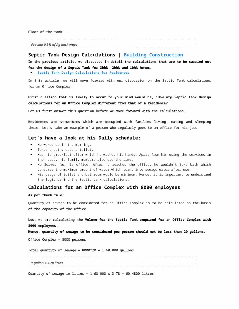
Calculations for an Office Complex with 8000 employees
As per thumb rule;
Quantity of sewage to be considered for an Office Complex is to be calculated on the basis of the capacity of
the Office.
Now, we are calculating the Volume for the Septic Tank required for an Office Complex with 8000
employees.
Hence, quantity of sewage to be considered per person should not be less than 20 gallons.
Office Complex = 8000 persons
Total quantity of sewage = 8000*20 = 1,60,000 gallons
1 gallon = 3.78 litres
Quantity of sewage in litres = 1,60,000 x 3.78 = 60,4800 litres
Volume of Sewage in cubic metres:
60,4800/1000 = 604.8 cubic metres

Volume of Sewage in cubic feet:
604800/28.52 = 21206.17 cubic feet
Dimensions of a Septic Tank for an Office Complex in Metres:
Length of the Septic Tank = 15m
Width of the Septic Tank = 13.44m
Depth of the Septic Tank = 3m
Dimensions for a Septic Tank in Feet:
Length of the Septic Tank = 49.5’
Width of the Septic Tank = 44.352’
Depth of the Septic Tank = 9.9’
How to design a Septic Tank?
A Septic Tank is a small scale sewage treatment system used in areas which have no
connection to the main sewage pipes that are provided by the Local governments or
private Corporations.
In this article, we will detail out all the calculations that are to be performed to get the required
volume of a Septic Tank with the help of examples.

Schematic Diagram of a Septic Tank
We would begin with a small scale example so that your concept of Septic tank design is clear.
Here are the thumb rules to be kept in mind which will help you in calculating the volume of a Septic Tank.
For a three bedroom house:
The quantity of sewage considered for a three bedroom house should not be less than 900 gallons.
For a two bedroom House:
The quantity of sewage to be considered for the design of Septic Tank should not be less than 700 gallons.
For one bedroom unit:
The quantity of sewage to be considered for the design of a Septic Tank should not be less than 550 gallons.
Let’s begin with an example of a three bedroom residence.
Septic Tank calculations for a three bedroom Residence
As per the thumb rule;
Quantity of sewage to be considered for the design of a Septic Tank = 900 gallons
1 gallon of liquid = 3.78 litres
Quantity of sewage in litres = 900×3.78 = 3402litres
Volume of Sewage in Cubic metres
3402/1000 = 3.402 cubic metres
Volume of Sewage in Cubic feet
3402/28.52 = 119.28 cubic feet
Dimensions of a Septic Tank in metres:
Width of the Septic Tank = 1.70m
Depth of the Septic Tank = 1.00m
Length of the Septic Tank = 2.00m
Dimensions of a Septic Tank in feet:
Width of the Septic Tank = 5.61’
Depth of the Septic Tank = 3.3’
Length of the Septic Tank = 6.6’
Various types of Roof trusses for various spansWhat is a Truss? In Architecture and Structural Engineering, a truss is a structure comprising one or more triangular
units constructed with straight slender members whose ends are connected at joints referred to as
nodes.
External forces and reactions to those forces are considered to act only at the nodes and result in
forces in the members which are either tensile or compressive forces.
Moments (torsional forces) are explicitly excluded because, and only because, all the joints in a truss
are treated as revolutes.
In this article, we are going to discuss the various types of roof trusses in wood and steel and their uses in
various kinds of construction.
Different types of Wooden and Steel Roof Trusses:1. King Post Truss
2. Queen Post Truss
3. Howe Truss
4. Pratt Truss
5. Fan Truss
6. North Light Roof Truss
7. Quadrangular Roof Truss
Trusses for large span constructions Tubular Steel Roof Truss
Tubular Monitor Steel Roof Truss
King Post Truss
King Post roof truss (spans upto8M)
King Post Truss is a wooden truss.
It can also be built of combination of wood and steel.
It can be used for spans upto 8m.
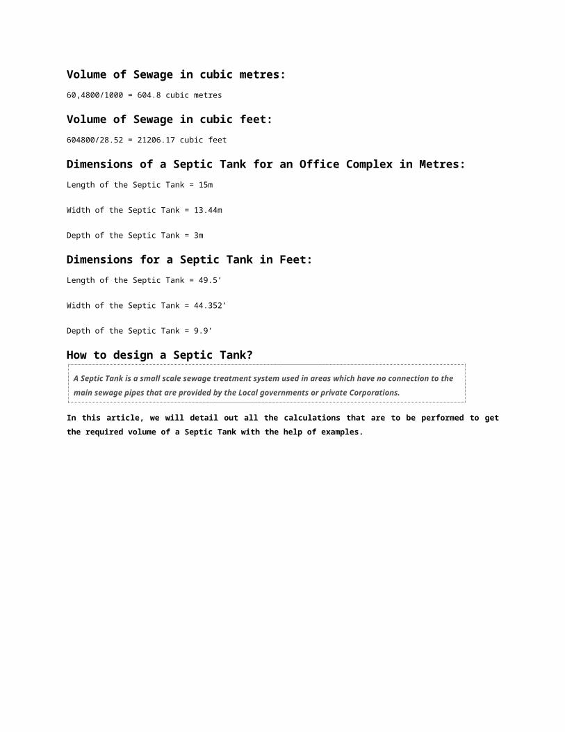
Queen Post Truss
Queen Post Truss (spans upto 10M)
Queen Post Truss is also a wooden truss.
It can be used for spans upto 10m.

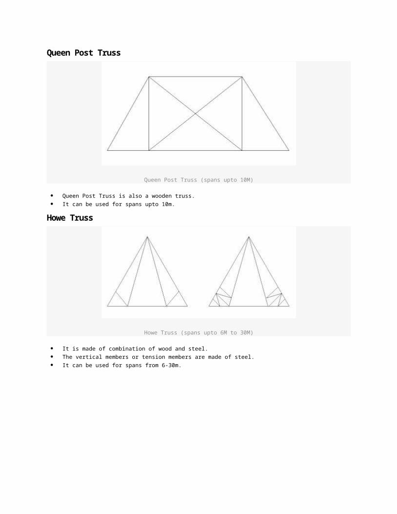
Howe Truss
Howe Truss (spans upto 6M to 30M)
It is made of combination of wood and steel.
The vertical members or tension members are made of steel.
It can be used for spans from 6-30m.
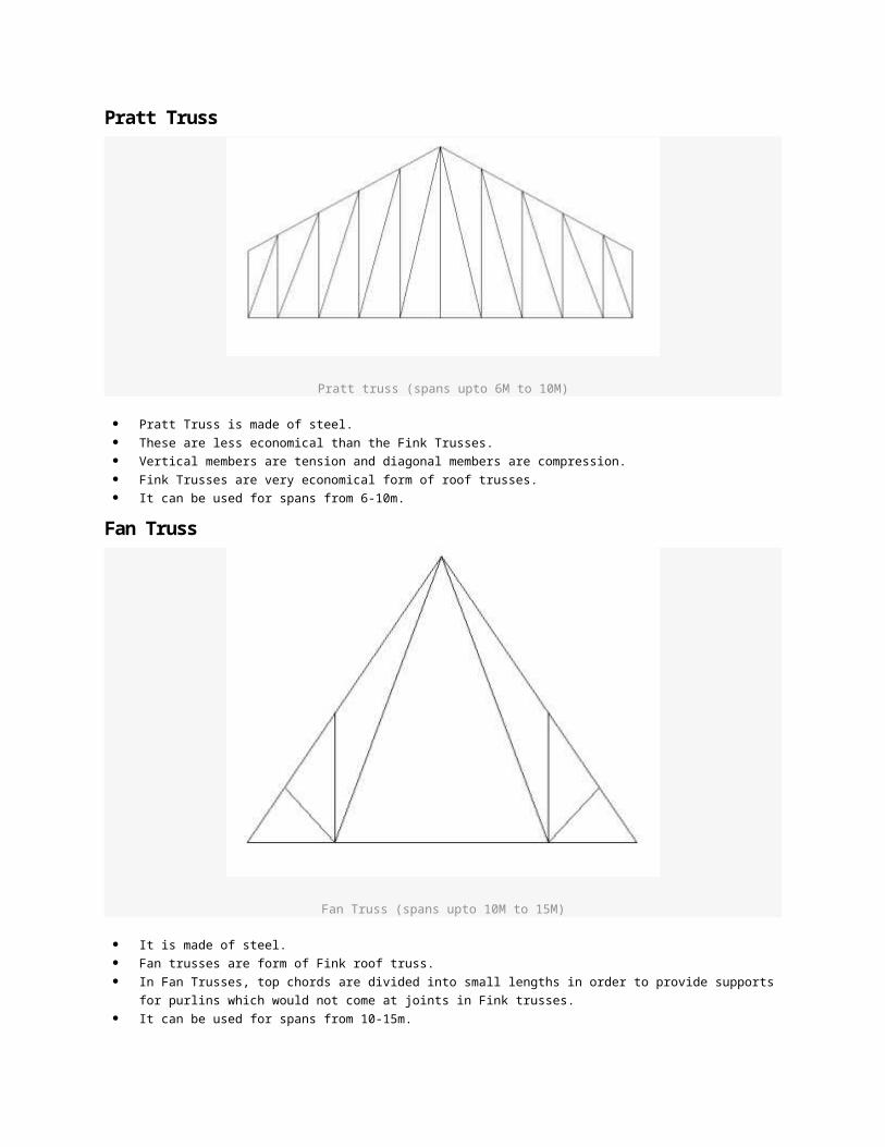
Pratt Truss
Pratt truss (spans upto 6M to 10M)
Pratt Truss is made of steel.
These are less economical than the Fink Trusses.
Vertical members are tension and diagonal members are compression.
Fink Trusses are very economical form of roof trusses.
It can be used for spans from 6-10m.

Fan Truss
Fan Truss (spans upto 10M to 15M)
It is made of steel.
Fan trusses are form of Fink roof truss.
In Fan Trusses, top chords are divided into small lengths in order to provide supports for purlins which
would not come at joints in Fink trusses.
It can be used for spans from 10-15m.
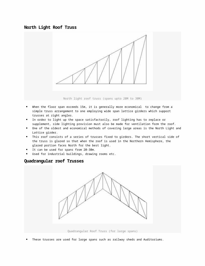
North Light Roof Truss
North light roof truss (spans upto 20M to 30M)
When the floor span exceeds 15m, it is generally more economical to change from a simple truss
arrangement to one employing wide span lattice girders which support trusses at right angles.
In order to light up the space satisfactorily, roof lighting has to replace or supplement, side lighting
provision must also be made for ventilation form the roof.

One of the oldest and economical methods of covering large areas is the North Light and Lattice girder.
This roof consists of a series of trusses fixed to girders. The short vertical side of the truss is glazed so
that when the roof is used in the Northern Hemisphere, the glazed portion faces North for the best
light.
It can be used for spans from 20-30m.
Used for industrial buildings, drawing rooms etc.
Quadrangular roof Trusses
Quadrangular Roof Truss (for large spans)
These trusses are used for large spans such as railway sheds and Auditoriums.
Large Span Trusses
Large span trusses
Tubular Steel Roof Truss | Trussed large span Constructions
Tubular Steel roof trusses are used for large span constructions such as factories, industry worksheds, shopping
malls, huge exhibition centres, multiplexes etc. They are generally used for spans as large as 25-30m.
There is a similar kind of a truss called “Tubular Steel Monitor Roof Truss“. There are projections on the roofs called
“Monitors” to admit daylight into the space.
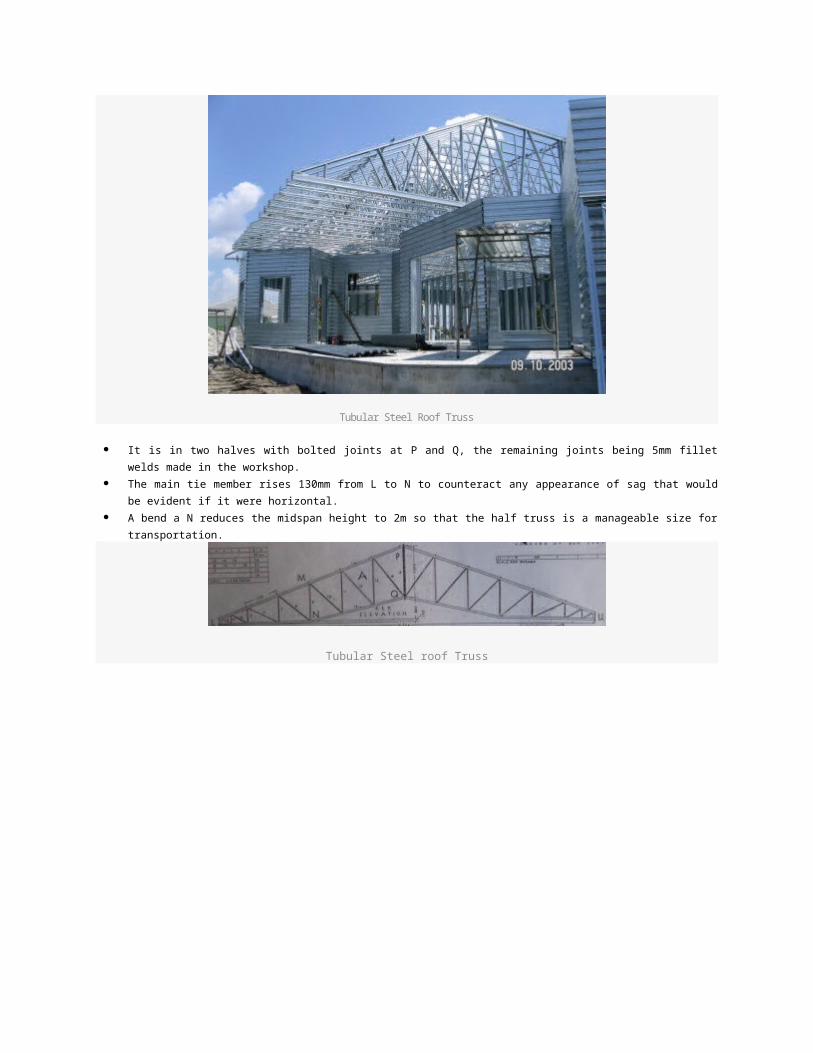
Tubular Steel Roof Truss
It is in two halves with bolted joints at P and Q, the remaining joints being 5mm fillet welds made in the
workshop.
The main tie member rises 130mm from L to N to counteract any appearance of sag that would be evident if
it were horizontal.
A bend a N reduces the midspan height to 2m so that the half truss is a manageable size for transportation.
Tubular Steel roof Truss
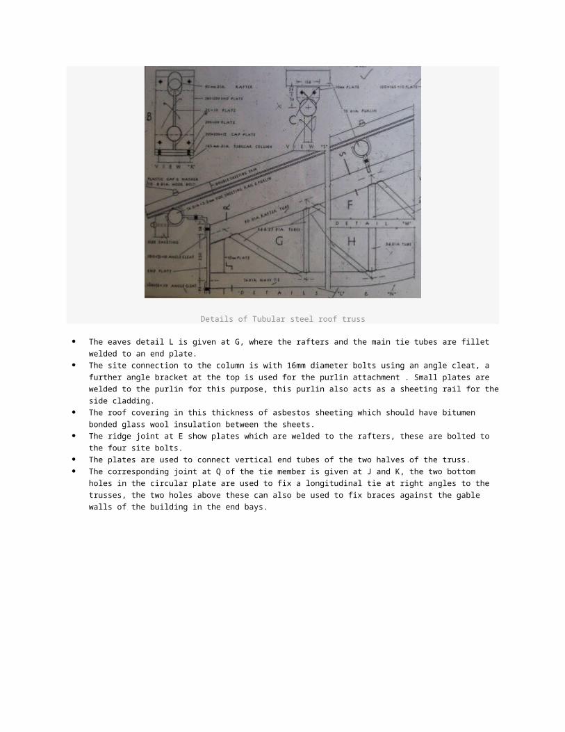
Details of Tubular steel roof truss
The eaves detail L is given at G, where the rafters and the main tie tubes are fillet welded to an end
plate.
The site connection to the column is with 16mm diameter bolts using an angle cleat, a further angle
bracket at the top is used for the purlin attachment . Small plates are welded to the purlin for this
purpose, this purlin also acts as a sheeting rail for the side cladding.
The roof covering in this thickness of asbestos sheeting which should have bitumen bonded glass wool
insulation between the sheets.
The ridge joint at E show plates which are welded to the rafters, these are bolted to the four site bolts.
The plates are used to connect vertical end tubes of the two halves of the truss.
The corresponding joint at Q of the tie member is given at J and K, the two bottom holes in the circular
plate are used to fix a longitudinal tie at right angles to the trusses, the two holes above these can also
be used to fix braces against the gable walls of the building in the end bays.
Steel truss on Terrace
Advantages of Tubular Steel Roof Trusses Structures designed for material handling equipments (e.g., a bridge and a tower crane) where weight
savings may be very substantial economic consideration.
30% to 40% less surface area than that of an equivalent rolled steel shape. Therefore, the cost of
maintenance, cost of painting or protective coatings reduce considerably.
The moisture and dirt do not collect on the smooth external surface of the tubes. Therefore, the
possibility of corrosion also reduces.
The ends of tubes are sealed. As a result of this, the interior surface is not subjected to corrosion. The
interior surface do not need any protective treatment.
They have more torsional resistance than other section of the equal weight.
They have a higher frequency vibrations under dynamic loading than the other sections including the
solid round one.
Sinking Foundation Damage and repair guideWe will discuss repair of Sinking foundation in three steps: Step 1 – Examination of the Structure by an expert
Step 2 – As soon as the problem is identified, hire a contractor or a foundation specialist
Step 3 – Methodologies or techniques used for sinking foundation repair
Step One: Identification and Examination of the Structure by an expert
As soon as you find any signs of foundation damage that we discussed in our previous article “Identifying
Sinking foundation”, you should immediately contact a professional (structural engineer). The first thing
that you should be doing is getting your house examined and checked properly for structural damage.
The structural engineer is an expert in this field. He will be able to tell you as to what has to be done in order
to prevent further damage and all that is required to be repaired. Sometimes people tend to think that
engineers might exaggerate about the damages occurred to the structure because of monetary concerns.
However, it should be kept in mind that the engineer has no vested interest in these kind of repairs. He is the

person who would give you an accurate and unbiased opinion. And with his help and advice, the work is then
carried out by the foundation specialists or a general contractor. This was all about STEP-1.
Step two: Hire a contractor or a foundation specialist
Now once you are aware of the problems in the structure, you should immediately hire a contractor or a
foundation specialist to do the repair work.
Generally, foundation repairs are pretty expensive. You need to be aware of the prices in the market. In
order to select a good contractor, you need to shop around and get several bids from different contactors.
Foundation repair is a crucial job and requires expertise. So experience would be one important factor which
you should consider while selecting a Contractor. Do check his previous work records to figure out if he is fit
for the job you want done.
Step three: Techniques for repairing a Sinking foundation
The question is, how could the sinking foundation be corrected or repaired?
Well, there are various techniques to fix a sinking foundation. The technique utilized for the repair of a
sinking foundation depends on the soil condition and damage occurred to the structure.
The most popular technique to fix sinking foundation is HIGH PRESSURE GROUTING.
As the name itself suggests, high pressure grouting is the method of injecting grout into the unstable soil at
high pressure. This helps in improving the integrity and stability of the soil. This method is also used if the
structure is to be lifted up.
Use of Load bearing Piers
Load bearing piers are used to repair the sinking foundation. It helps in lifting and stabilizing the foundation.
This method is economical in construction. It provides a permanent solution to foundation problems.
In some cases, even helical piers are used for the same purpose. The selection of piers depends on the
conditions of the soil and structural damage caused. These kind of peirs are especially useful where fill
material has been used and the water table is high.
Ceramic Tiles
Ceramic materials are an inorganic, non-metallic solid. They are prepared by the action of heat and
subsequent cooling. Ceramic materials have a crystalline or partly crystalline structure, or may be
amorphous. Because of its crystalline nature, ceramic tiles have a tendency to crack when put under
pressure.
Ceramic tiles
A ceramic material is an inorganic crystalline oxide which is solid and inert and hence does not react with
any chemicals. Since Ceramic is chemically inert, it can withstand chemical erosion that occurs due to other
materials in the surroundings that react with acidic substances. Ceramic materials are brittle, hard, strong in
compression, weak in shearing and tension.
In this article, we are going to discuss the method of fixing Ceramic Tiles over Large Floor Spans
and the method of replacement of tiles.Fixing of ceramic tiles in a Large Hall
Fixing of ceramic tiles in a Large Hall
A grid is made in the large hall. The grid should not exceed 8’x10’.
6mm groove is made in between each box of the grid so that when the tiles expand, they don’t result
in breaking.
Reasons for the breaking or cracking of ceramic tiles
The adhesive used for ceramic tiles is cement mortar. When the mortar mix in not made in the correct
proportion, the ceramic tiles result in popping up.
Ceramic tiles are delicate. If excessive load is kept over them, they result in cracking.
If ceramic tiles are laid continuously over large spans without any grooves between them, then they
result in popping up and breaking, since ceramic tiles have the ability to expand.
Replacing the broken ceramic tiles
There are three important steps to be followed for the replacement of the broken ceramic tile:
Step one:
While removing the broken ceramic tile, we should take care so that the tiles around the tile to be removed
are not damaged. Cut the tile from the inside of its edges so that other tiles don’t get chipped off. Then take
a chisel and hammer and slowly chisel out the the edges of the broken tile from the floor.
Chipped Ceramic tile that is to be removed is circled
Method of removal of the broken Ceramic Tile

Step two:
Scrape out the old adhesive that is cement mortar from the floor.
Method of Luppm Finish and Cleaning of pinhead glass | Building Construction
This is a simple article which deals with two different topics explained in a very brief manner. I hope it will be
helpful to the students of architecture and Engineering….
How would you clean a 3mm pinhead glass?
Usually, a chemical called as “aerosols” are used for cleaning 3mm pinhead glass.
The welded design on the pinhead glass can be made plain with the help of some chemical powder and then
rubbing the glass with a sandpaper.
How would you luppm finish on an already painted wall?
Oil paint + whiting powder= luppm paste is made.
The paint and plaster of the already painted wall is scraped out.
Then the wall is made rough by chiselling or the wall is brushed by a “wire brush” that makes the wall rough.
Rough surface holds the plaster properly.
Now, luppm is then applied with the help of a “luppm applicator”.
Then it is left to dry for 12 hours.
The luppm walls are then rubbed with sandpaper for achieving smooth finish.
Then a coat of primer is applied. After the drying of primer coat, plastic paint or any desired type of paint is
applied.
Defects in Buildings | Building Materials used in Construction
In my previous article, we began with a discussion on Building Materials used for Construction. We have
already discussed the two major building materials such as Sand and Mud. Now we will go on and discuss the
role of water, Cement and Cement Mortar in Construction.
Water in Construction
Salt free water should be used on the construction site for the mixing of cement. If salty water is used in the
construction, it will result in formation of cracks in the building.
For example: Vishakhapatnam in Andhra Pradesh, India has brine water below 100’. That is why, the
bore cannot be dug to more than 80’ feet for water to be used on the construction site.
Cement in Construction
There are various grades of cement available for the purpose of construction.
For example: M15, M20, M25 etc
The grade of cement to be used for construction is decided on the basis of the kind of construction and the
structural design.
Cement is always used along with steel, that is RCC (Reinforced Cement Concrete) construction. Only
cement cannot be used because it develops cracks.
Grooves are made over the layer of cement mortar.
For example: When cement flooring is done, a thin layer of cement is laid and grooves are made on the
cement layer to prevent cracks.
Ratios of cement and sand in Mortar, RCC, Plastering and flooring
Cement +sand = Mortar
1 cement + 2 sand +4 steel = RCC
1 cement +6 sand = Plastering
1 cement + 8 sand = flooring
Role of Cement Mortar in Construction
Reasons for the development of cracks in cement mortar used in construction:
Too much cement
Too much water
Too much sand
Too less water
No curing or less curing
Vast expanses of plaster
Expansion co-efficient is different for different materials
For example, the co-efficient of expansion of wood is different from that of cement concrete.
That is why when cement concrete is used to along with wood, the bonding is not very strong.
Taking note of expansion co-efficient of various materials for the strength of the construction and proper
bonding of materials to be used on site.
Causes of Foundation damage and Retrofitting
In one of my previous articles, we discussed various steps in which the survey of the foundation
has to be done in order to be considered for retrofitting.
In this article, we will discuss various reasons or causes for the damage of the foundations.
Types of foundation damage can be classified as follows:
Erosion
1. Natural rock
2. Brick
Rot

Insects
Moisture damage
1. Frost wedging
2. Salt bloom
Settlement in the ground
1. Groundwater lowering
2. Limited bearing capacity of the ground (land)
3. Uneven bedrock depth
4. Excavations performed below the foundations and poor quality of backfill
5. Increased load on the ground leading to failure
6. Damage to the neighbouring houses
7. Horizontal movement occurring in the ground
Frost heave/adfreezing
Alum shale
Now we will move on with the discussion in detail on the types of foundation damage occurring
due to Settlement in the ground.Lowering in the Groundwater level
When the buildings are built on compressible soils, the resulting stress on the soil causes the soil to
compress. Raft foundations are used in these kind of soils.
Since the soil undergoes compression the upper portion of wooden piles rot when groundwater level sinks.
There are various conditions which can cause the changes in the groundwater level or pore water pressure. They are as follows: Ice Static Rebound
Dewatering (seen in cities)
Ditches and pipes below the groundwater level
Deep Foundations and Basements (causing further drainage of the ground
Tunnelling
By the removal of foundation sills
Construction of non-permeable surfaces such as roads, pathways causing the least amount of natural
precipitation
Use of deciduous trees should be avoided in areas with low groundwater. They require a lot of water for
their growth. They pull all the water that is available around them causing the lowering of groundwater.
Limited Bearing Capacity of the Ground
Earlier, when the science of engineering and surveying wasn’t much developed, people failed to understand
that it was important to analyze the nature and bearing capacity of soil. In case the soil was weak in nature
and underwent compression, it would lead to settling problem.
This has been observed in some of the old buildings. In some cases, the foundation wall developed cracks
which ultimately resulted in the failure of the structure.
Uneven Bedrock Depth (varying bearing capacities in the same patch of land where the construction is to be initiated.)

Analyzing the nature of the soil is important which most importantly deals with its bearing capacity. It is to
be remembered that if the building is constructed on two different types of soils having different bearing
capacities, it could lead to dislocation of the structural components.
For example:
If a building is constructed partially on bedrock and partially on fill mass. Since they have poor bearing
capacity, there will be a difference in the settling of the structure.
The first consequence that will be seen will be the occurrence of cracks on the walls of various floors. It
might also result into instability of the structure.
Foundations under which excavation is done and poor backfill
If in case excavation is to be performed under a foundation, it is important to note that the ground conditions
are favourable and will not result into settling.
If the loads are loads and ground stability is not checked before performing excavation below the foundation,
it could result into settling.
Increase in the Load
Buildings are designed with giving full considering to the maximum load that will be imposed on the
structure. If these buildings last for years without undergoing damage, that is because the load on the
structure is maintained and is not in excess which would result in the instability of the structure.
If in case changes are made in the loading conditions of the same building. It result into settlement of the
structure causing excessive damage to the foundation.
Damage caused to the neighbouring houses
In cities, the buildings are constructed close to each other. If one of the building is demolished for
reconstruction of a structure serving a different purpose, it might lead to the occurrence of a slide having
severe consequences on the stability of the surrounding buildings in its vicinity.
Building Materials used in Construction | Defects in Buildings
The building materials used for construction of the building are the major factors of a successful structure or
a failed structure. The major core materials that are responsible for the standing structure are:
1. Sand
2. Mud
3. Cement
4. Water
5. Cement Mortar
Usually, the failure of a building is due to the development of cracks. The intensity of damage describes the
kind of crack and the repair measures to be taken….
There are two major types of cracks:

1. Minor causes of Cracks resulting in minor cracks or surface cracks in Buildings
2. Major causes of cracks resulting in major cracks or structural cracks in Buildings
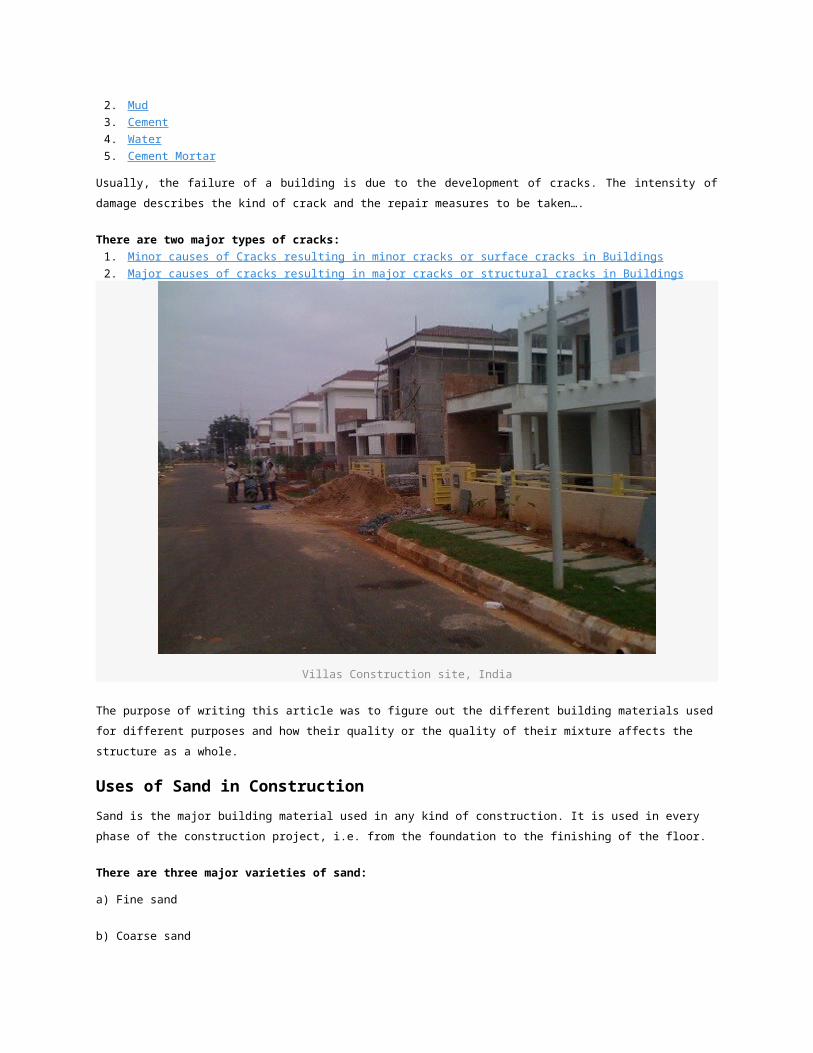
Villas Construction site, India
The purpose of writing this article was to figure out the different building materials used for different
purposes and how their quality or the quality of their mixture affects the structure as a whole.
Uses of Sand in Construction
Sand is the major building material used in any kind of construction. It is used in every phase of the
construction project, i.e. from the foundation to the finishing of the floor.
There are three major varieties of sand:
a) Fine sand
b) Coarse sand
c) Medium sand
Fine sand is usually used for the topmost plastering of the surfaces.
Plastering is done in two coats: Rough coat and Final coat.
Coarse sand
It is generally used in RCC work and in the foundations of the Super – Structure.

Medium sand
It is used in the mixture of mortar and while laying the flooring tiles.
Stone dust
Baby chips are coarse. They could be used in the concrete mixture as a substitute to Coarse sand.
• 1bag of cement + 6 ghumpas of sand + 7 ghumpas of stone metal
• 1bag of cement + 5 ghumpas of sand +1 ghumpa of dust + 7 ghumpas of stone metal
These are the suitable proportions for a “Cement Concrete Mixture”.
Uses of Mud in Construction
Mud should never be used alongwith sand. It destroys the strength of the structure.
Before sand is to be used for the purpose of construction, the sand test should be performed.
(sand + water = sand test)
Filter beds are also used to clean the dirty sand. They are rejuvenated every few months.
Cement is nothing but crushed limestone. After the limestone is crushed, some chemicals are added to
increase the durability of cement.
MARKET SURVEY
A bag of crushed limestone costs =50/-
Cost of crushed limestone treated with chemicals = 250/-
Some contractors use just crushed limestone instead of chemically treated crushed limestone on
the construction site to make profit. In Practice, the quality of the mixture and the materials
used are not really paid much attention to which is very bad and results in substandard
construction.
We as Architects and Engineers should take a vow and prevent this from happening atleast in
our own projects…
What would you do in case of a RCC staircase having cracks?
The development of cracks occurring in RCC staircase is one of the major problems to deal with in RCC
construction.
Before we go to the ultimate solution of the repair of cracks in a staircase, I would want all the students to
know that, “Design in a way that you would never have to look for solutions”.
This is an important matter. The graver the problem, the harsher and shorter the solution is….

Basic elements of Staircase
Earlier, in one of my article, I have explained the “Design of RCC Staircase”. Please do go
through before designing….
RCC staircase cracks
There are two types of cracks, they are;
1. Minor cracks or surface cracks
2. Major cracks or structural Cracks
Like I said before, the graver the problem, the shorter and harsher the solution….
In case of minor cracks (surface cracks) occurring in the RCC staircase , the cracks can be filled up with
the help of plastering. Surface cracks are not very harmful to the structure. They only result in marring the
aesthetics of the built space.
In case of major cracks (structural cracks) that is causing vibrations when someone walks on the
staircase, the staircase has to be broken and then recast again. (Remedy is as short as it could be)
How to calculate the steel quantity for columns and beamssteel quantity is found by multiplying ( number of bars*length of one bar*unit weight of steel) where unit weight of steel is D^2/162,D-is dia of bar. Same procedure for stirrups and links.

steel quantity = 1% of concrete quantity(in general for calculation of quantity)
NO OF BARS * LENGTH OF BAR * D^2/162
actor of safety used in working stress method partial safety factor used in limit state method
MBOOK means measurement book which is used in construction filed to record thge executed quantity of worksM.Book means Measurement Book. All the measurements of awork are to be recorded in it. The M.Book normally contains100 pages and issued by Executive Engineers certifying theperson to whom issued. It consists of the following columns.
Date of Description Nos L B D/H Qty. Rate Amountrecording
mainly m book is used to note the instruction given byexecutive enginneer at the site, but any engineer whether JEaur AE , there instruction can also be noted down inmeasurement book
A]EARTHROADSOrdinary earth roadStabilized earth roadB]GRAVEL ROADSC]WATER BOUND MACADAM ROADSD]BITUMINOUS ROADS1.Surface painting road or surface dressing road2.Bituminous macadam road3.Bituminous concrete road4.Sheet asphalt road or asphaltic matE]CEMENT CONCRETE ROADS
Why chairs are provided at slab?chair is used to maintain minimum space of double layerreinforcement.
floor area ratio is also known as floor space index {FSI} it is use to control number of floors with respect to plot area, it is calculated by dividing total floor or built up area by plot area. for mumbai is limited to 1.33.
in pretensioning the tendons(steel rod) are streched so that stress in induced in tendons before concreting eg.railway sleepers or beams
in post tension stresses are induced after the concreting is done
why we are placing the beam under the plinth wall?so that movement of soil due to rain or else may not produce cracks in the wall.
Why we select pile foundationsBecause of Low bearing capacity of soil we go for pile foundation whenever load of the structure is very large and bearing capacity of soil is low pile is provided to get benefit of skin friction along with end bearing.It is common in costal area of india.
WHY DO WE PROVIDE DEVELOPEMENT LENGTH AND EXTRA BARS AT TOPnegative moment normally require providing extra additional bar at the top of horizontal concrete casted members that often positioned within the area supported by column/wall.the top extra length should exceed the inflection point between negative and posetive moment. Development length is provided for ancorage stress or to provide anchorage length (bonding stress)of steel in concrete.steel bars are provided as per failure pattern of the structure if steel is not present to take tension.At ends /supports due to fixity negative moment is developed which is resisted my steel at top.the top extra length should exceed the inflection point between negative and posetive moment.
50D to 60D is the thumb rule for lap length, the lap length depends upon grade of concrete and thickness of steel bars yes it is coorect that it is the thumbrule for lap length eg.50D OR 60D.the lap length varies as per grade of concrete ,grde of rienforcement bar and most importnat is the position of bar also whethere it may be in flexural tension,direct tension or direct compression say in m20 gradenormally 41d for lap length
density of flyashFly ash Density - 1.90 - 2.55
weight of 32mm rod/mVolume of 32mm rod/m = (3.14/4)*32*32*1 = 804.57 mmsqMass/Volume = Density, Density of steel 7850 Kg/cumThere fore Mass = (804.57/1000*1000)*7850 =6.315 Kg.
FormulaWeight of rod/m = D*D/162 Where D = Dia of Bar in mmWeight of 32mm Rod /m = 32*32/162 =6.3209 Kg.
wht is off shore structureA structure away from the shore, like an oil platform at Bombay high.
An ideal fluid is one which has no friction(viscosity)during its movement.
Q:What is the formula of bar to bent the slab in bent slab?Second question Q: what is formula to calculate the hook?one Hook length is equal to 9D. . The bent up for end slab is L/7.for continuous slab it is L/5.For hooks it is 7x dia for each hook
what is a steel formulaSq Dia / 164
Eg for 12mm rod
(12*12)/162
= 144/162
= .888 Kg/Mt Weight of Steel For 1m Length=(Square of Bar Diameter)/162
For Example:
Take 8mm Diameter Bar Weight For 1m Length;i.e.
8*8/162=0.395Kg For 1m Length
Weight of bar per meter = Area of steel bar X Density of steel x Length of bar= (3.14 x D2/4) x 7850 kg/m3 x 1000 mm= (3.14 x D2/4) x 1000 x 7850 / (1000 x 1000 x 1000)= D2 X 785.714285714286 x 0.00000785= D2 X 0.006162 = D2 X 1/(0.006162) = (D2/162.28)
In two way slab where should we stop the work at end of the day?
t should be a little ahead towerds center form point of contraflexure to allow for bonding roughfly @ L/3 from either ends for two way slab. at L/3 from either end
what is the percentage of binding wire required for 1 mt of steel binding in gerallyIn bridges wastage is very less, so 8 to 9Kgs (.8% to .9%) may be preferred. what is minimum steel area required for rcc slab0.12 to 0.15% of total area
WHAT IS THE LAP LENGTH FOR COLUMN WITH DESIGN MIX M-35 RCC45d (d is The diameter of bar) as per iS-456 this is depending on grade of concrete andalso grade steel
i.e.,
ex:-grade of concrete -M35Grade of steel-Fe415bars are deformedThen development length 26.55d
where d=dia of bar