impact final report (texas as6 univ.) ~2-3-p bc $4.25 cscl
TRANSCRIPT

HYDRODYNAMIC
WATER
IMPACT
(NASA-CR-137370) HYDRODYNAIC WATER N74-19915IMPACT Final Report (Texas AS6 Univ.)~2-3-p BC $4.25 CSCL 20D
UnclasG3/12 35039
C.F. Kettleborough
Texas A&M University
College Station
Texas 77843
March 1972
https://ntrs.nasa.gov/search.jsp?R=19740011802 2020-03-23T11:19:06+00:00Z

SUMMARY
The hydrodynamic impact of a falling body upon a viscous incompressible
fluid is investigated by numerically solving the equations of motion. Initially
the mathematical model simulated the axisymmetric impact of a rigid right
circular cylinder upon the initially quiescent free surface of a fluid. A
compressible air layer exists between the falling cylinder and the liquid
free surface.
The mathematical model was developed by applying the Navier-Stokes equations
to the incompressible air layer and the incompressible fluid. Assuming the
flow to be one dimensional within the air layer, the average velocity, pressure
and density distributions were calculated. The liquid free surface was allowed
to deform as the air pressure acting on it increases. For the liquid the
normalized equations were expressed in two-dimensional cylindrical coordinates.
The governing equations for the air layer and the liquid were expressed
in finite difference form and solved numerically. For the liquid a modified
version of the Marker-and-Cell method was used. This method, developed by the
Los Alamos Scientific Laboratory, is especially suitable for solving time-
dependent fluid flow problems involving a free surface.
The mathematical model has been reexamined and a new approach has
recently been initiated. Essentially this consists of examining the impact
of an inclined plate onto a quiesent water surface with the equations now
formulated in cartesian coordinates.
2
INTRODUCTION
One of man's earliest serious investigations of hydrodynamic impact was
with the problem of ship slamming. He learned throughout the centuries by
experimentation that he could minimize the damage due to slamming by varying
the size, shape, supporting structure and mass of the hull. The ship slamming
phase of hydrodynamic impact is still being studied in great detail today.
Advances in technology ultimately led to a study of the impact of seaplane
floats during landing, the water impact connected with the laying of mines,
the dropping of depth charges, the launching of torpedos, the dropping of
oceanographic instrument packages and more recently the water landing of
returned manned spacecraft. A knowledge of the pressure distribution during
impact is necessary to be able to design a spacecraft for landing.
The hydrodynamic impact problem is a very difficult one because the
.physics 'of-what actually -happens during the instant of impacts-i-s;-not understood.
Many theoretical studies have been reported and in general did not closely
agree with experimental results.
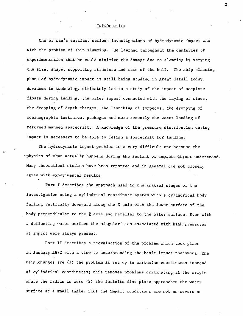
Part I describes the approach used in the initial stages of the
investigation using a cylindrical coordinate system with a cylindrical body
falling vertically downward along the Z axis with the lower surface of the
body perpendicular to the 2 axis and parallel to the water surface. Even with
a deflecting water surface the singularities associated with high pressures
at impact were always present.
Part II describes a reevaluation of the problem which took place
in January-1972 with a view to understanding the basic impact phenomena. The
main .changes are (1) the problem is set up in cartesian coordinates instead
of cylindrical coordinates; this removes problems originating at the origin
where the radius is zero (2) the infinite flat plate approaches the water
surface at a small angle. Thus the impact conditions are not as severe as

3
in the original case. It is hoped that the results can be extrapolated
to the case where the angle is zero.

4
LITERATURE SURVEY
Von Karmen (1) was one of the first to investigate impact in his 1929
study of the impact on seaplane floats during landing. When conservation of
momentum is applied at impact, the body velocity is found to decrease and the
total mass to increase due to water set in motion by the body. This increase
in mass was called the "added apparent mass." Chu and Abramson (2) provided
an excellent review and bibliography on the theories of hydrodynamic impact
through 1961. They suggested consideration of compressibility effects during
the initial stage of impact and the use of numerical techniques. Jensen
and Rosenbaum (3) developed a mathematical model to study water impact of the
Mercury Space Capsule by modifying Von Karmen's theory. The spherical bottom
of the capsule was represented by a series of wedges with a 100 deadrise angle.
It was found that accelerations obtained from this mathematical model were
initially less than those obtained experimentally for vertical impact.
Moran (4) published a detailed survey of hydrodynamic impact theories
through 1964. He stated that the inclusion of compressibility effects removed
some of the glaring defects of the earlier theories but compressibility of
the water is not very important for the water-entry of a blunt - or round-nosed
body at low speeds. Re recommended the consideration of a finite air layer
between the body and the water. Because the free surface at the impact point
has already accelerated to the body speed the inclusion of air density effects
eliminates the abrupt velocity change at impact. This velocity discontinuity
is responsible for the infinite pressures found in earlier impact theories.
Li and Sugimura (5) presented an analysis of the water impact of the
Apollo Command Module in 1967. The impact of a rigid sphere upon a quiescent
incompressible inviscid sea was assumed. A compression wave was considered
at the first point of impact to prevent an infinite initial impact pressure.

The answer was given in the form of an infinite power series. Verhagen (6)
presented an excellent publication on the investigation of the impact of an
infinite flat plate when dropped vertically on an undisturbed water surface.
A compressible inviscid air layer is assumed to exist between the plate and
water surface. The water is considered incompressible. A deformable free
surface is considered and impact is said to take place when the deformed free
surface touches the edge of the plate. Verhagen found that impact appears
to take place when the air velocity at the edge of the plate almost reaches
acoustic velocity. The pressure distribution was smoothed to prevent
singularities in the mathematical evaluation of the problem.
Kurland (7) in 1968, presented a review and comparison of all model and
theoretical studies involving water landing loads on the Apollo Command Module.
Lewison and Maclean (8) investigated the impact between a rigid flat plate and
a free water surface with a compressible air layer. They postulated that the
compression of the air under the plate sets the water surface in motion
downwards and eventual impact occurs with vanishing relative velocity and
hence infinite pressures do not occur.
Experimental tests on hydrodynamic impact are reported in references 9
through 14. The impact phase of the Apollo Command Module were studied in
1964 by Herting, Pollack and Pohlen (9). Full scale boiler plates were used
to investigate the pressure loads on the craft during impact and the flotation
characteristics after impact. Benson (10) in 1965 compared full-scale and
model data obtained on the Apollo Module during water impact using a modified
von Kdrman analysis. Theoretical and model studies compared favorably.
In 1966 Chuang (11) investigated rigid flat-bottom body slamming by dropping
steel plates from various heights above a calm water surface. He found
that because of the effect of the trapped air between the falling body and
the water, maximum impact pressure was much lower than expected if the generally

accepted acoustic pressure formula were applied. Baker and Westine (12) in
1966 studied water impact of the Apollo Module using 1/4.5 scale models.
Data obtained from heavily instrumented models was compared with results of
full scale experiments yielding good predictions of pressures, acceleration,
displacements and impact velocity. In 1967 Chuang (13) dropped flat-bottomed
and wedge-shaped bodies from various heights and found that maximum pressures
occurred before the water came in contact with the impact surface of the flat
bottom. For models with a deadrise angle of 30 or greater, most of the air
escaped at the moment of impact. With a smaller deadrise angle, relatively
large amounts of air were trapped to give a cushioning effect.
Thompson (14) investigated the rough water landing characteristics of a
Gemini-type spacecraft in 1967 using a 1/6 scale model. Gerlach (15) in
late 1967,.experimentally investigated the importance of air density and other
real fluid properties with respect to the water impact of small blunt rigid
bodies. He found that the restriction of airflow reduced the peak impact
pressure and that a small amount of air is actually trapped under the model.

Part ITHEORY
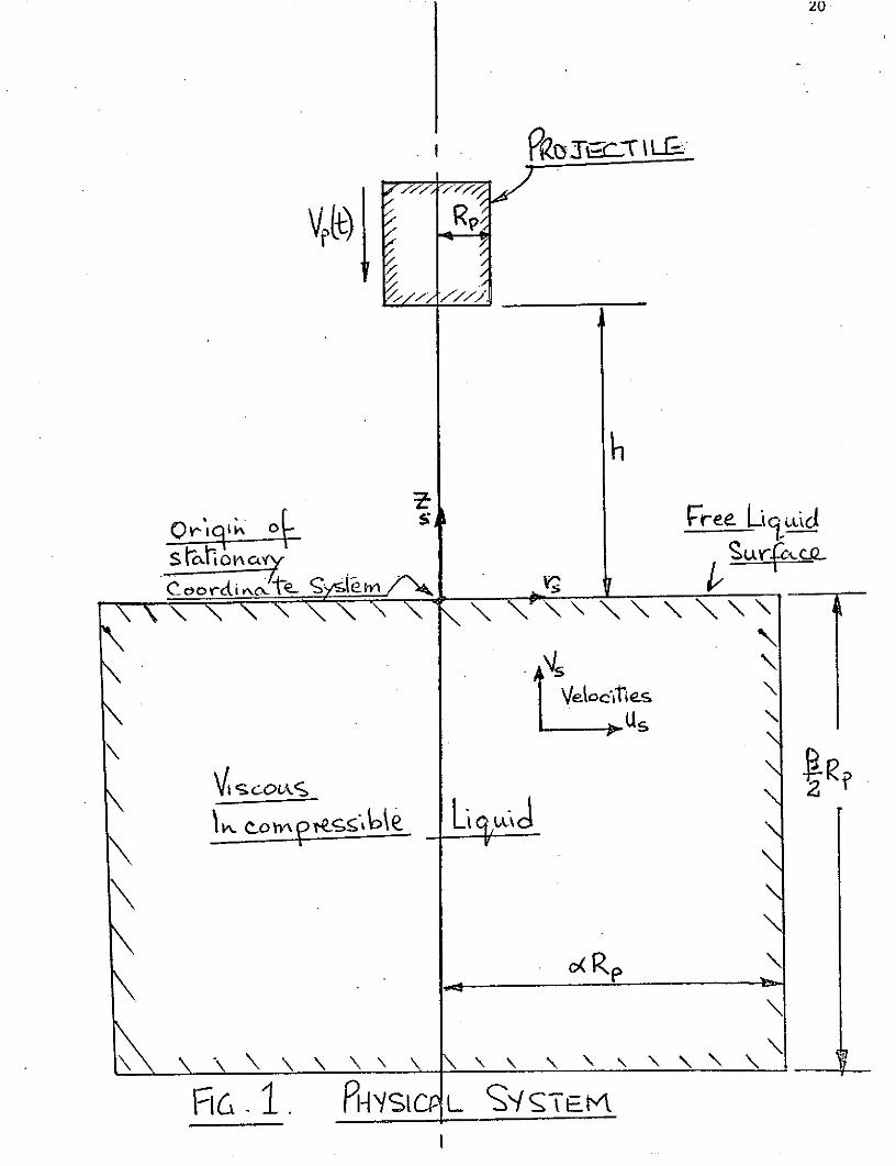
The case under consideration is that of a rigid right circular cylinder
falling axisymmetrically toward the quiescent free surface of a viscous in-
compressible liquid. The cylinder of radius R is initially a distance h
above the free surface and is falling with a current downward velocity of v (t)
as shown in figure 1. A compressible air layer exists between the falling
cylinder and the free surface. The behavior of the compressible air layer is
studied as the cylinder approaches the free surface. The effect of the air
layer on the liquid free surface and pressure and velocity fields is determined.
The problem is simulated by holding the cylinder stationary and moving the
entire mass of liquid toward the cylinder.
Since the system is axisymmetric a two-dimensional system is utilized.
The governing equations are
The origin of the moving coordinate (1)
the base of the falling projectile (see figure 2) and hence
="=-- + . . . = s (6)

Variables without subscripts are variables in the moving coordinate system,
The equations (1), (2) and (3) become
r ar
rt rbr r/LLz br i (8)
"r -2+ 2 _L
Defining dimensionless parameters as
r Z -Lot to
equations.(7), (8) and (9) become

u,_ u' . LR UV L _ LL V L Z. (12 )V
r-r
The equation for the pressure distribution is determined from equations
(12) and (13) and becomes
R 2 9aZI 2 111 (14)
- L r P + ' R sr 32 R R r)
Initial and boundary conditions
The following conditions exist at time zero. A thin layer of compressible
air of constant thickness h is between the clindrical body and the liquid.
The entire mass of liquid is moving upwards with a velocity v . Hydrostatic
pressures exist throughout the liquid.
The boundary conditions prior to impact are shown in figure 3. During and
after impact the boundary conditions are shown in figure 4.
Properties of the air layer
As the cylinder falls, the air rushes from beneath it. The outward air
velocities become quite large as the cylinder approaches the free surface and
the thickness of the layer becomes small. It is assumed that the compressible
air behaves such that pvn = k where li n , 2.
The continuity equation for a compressible air layer is
---')>. _ . (15)aR~K~ /

10
Substituting
= (16)
and expressing the time derivative in explicit form
P a Q{r r - a:The average radial component of air velocity Ua is obtained by applying the
R-direction momentum equation to the air layer which after simplification
becomes
-', -v-m + (18)
LT- c3 RR RC -%
Solving for the term aU /aT
4_ U-- - (19)
'The air velocity distribution is obtained by integrating equation (19)
explicitly.
The deceleration of the projectile is found by applying Newton's law of
motion. Before impact the deceleration force is that due to the air pressure
in the air layer. After impact the retarding force is that due to water
pressure in contact with the bottom of the projectile and the viscous drag of
the liquid surrounding the projectile as it penetrates below the water sur-
face. The velocity of the projectile is then found from
L C1 (20)
and the change in air layer thickness is
Lnk -v At (21)

COMPUTATIONAL DETAILS
The equations for the air layer and the water are set up in finite dif-
ference form as described in the MAC report (reference (16)). The two
components of velocity, u and v, are determined explicitly. It was found
that, for any cell, the components of velocity did not satisfy the continuity
equation. In order to ensure that this equation was satisfied the v component
was found from equation (II) and the u component from equation (12).
The order of calculations, stated briefly, are
Define air and liquid properties
P from equation (17)a
U from equation (|9)
Pa from equation (16)
Determine deceleration of projectile
Determine velocity of projectile
Determine air layer thicknessJ - - - - -u.-----
Determine pressure distribution in water I equation (14.)
Determine v component of velocity-equation (ll)
Determine u from equation (12)
Determine if impact has taken place
Move liquid markers and find new free surface of fluid
Many details involving free surface treatment, marker movement,
cell flagging, velocity reflections are found in the basic MAC Report.
The compressible air layer is used to generate pressure and velocity
boundary conditions in the free surface before impact and used in the
calculation of the free surface velocity and deformation.
It is to be noted that all variables are calculated explicitly which

12
automatically means that the time step of integration is very small. In the
initial stages of the problem solution several hundred time cycles may be
executed in the air layer before the air pressures increase enough above
atmospheric pressure to influence the behavior of the liquid free surface.
During this part of the problem solution it is not necessary to enter the
liquid calculations until many cycles in the air layer are completed. Once
the pressures, densities and velocities in the air layer begin to build up,
they increase very rapidly with time. This rapid buildup limits the magnitude
of the time step.
As the projectile became close to the water surface the velocity of the
outflow of the air became large resulting in a relatively large velocity
gradient at the water surface. This was allowed to act on the water sur-
face in order to produce radial motion of the water at the surface.
Because the area of most interest is that adjacent to the impact zone,
experiments were.per.formed with a variable mesh, using a fine mesh .near the
origin of coordinates and an increasingly coarse mesh as the spatial variables
moved away from the origin. However as the stable time limit is decided by
the smallest mesh size this procedure was abandoned and a constant mesh size
in each direction was used.

13
IMPACT CONDITIONS
The conditions that prevail immediately before or at impact is not known.
The problems of velocity discontinuities and infinite pressures at the impact
surface have always been present in hydrodynamic investigations. The pressures
in the air layer increases as the projectile approaches the water surface
and the water surface is depressed. However, none of the existing theories
prevented the velocity singularity occuring, i.e., at the position where con-
tact between the projectile and the water took place the vertical component
of velocity had two different values at the same time.Lewison and Maclean (8 )
were the first to state that the condition of impact was when the relative
velocity between the cylinder and free surface becomes zero. However in-
spite of numerous numerical experiments involving grid size and time interval,
the velocity discontinuity always existed. Because of the entrapped air
contact initially took place around the periphery of the projectile, the water
surface below the projectile being concave up. The air layer pressures in-
creased rapidly as the body became nearer. the surface being always a maximum
on the centerline and decreasing radially outwards. In spite of many numerical
experiments there was always a relative velocity between the body and the
adjacent water surface. If when initial contact took place velocity of the
water surface was instantaneously made equal to the projectile velocity and
continuity satisfied by recalculating the radial velocity in the surface cell
the pressures near the projectile became negative!
It is felt that future work should be concentrated on ascertaining the
conditions prevailing immediately before and at impact.

14
EXPERIMENTAL WORK
Experiments were initiated to investigate the motion of the water during
impact and hence derive a distribution of pressure by numerically integrating
the equations of motion.
A large rectangular tank was constructed from lucite and filled with water
to a depth of three feet. A right circular cylinder was used as the falling
object with its axis parallel to the water surface. It was sufficiently long
so that at the vertical center line plane two dimensional motion would be
accurately obtained. A number of colored beads was suspended in the water at
this centerline plane. The impact of the falling cylinder impacted on the
water surface causing the water to be displaced together with the suspended
colored particles. The motion of these particles was recorded by high speed
motion film photography. Frame by frame examination of this film would
..enable,the velocity components to be determined.
Experimental tests did not prove satisfactory for the following reasons.
(a) There was always a small movement of the suspended particles. It proved
impossible to find particles with exactly the same density as water.
(b) The particles could not be constrained to move in one vertical plane.
(c) The particles had to be sufficiently large for photographic purposes and
consequently did not behave as a water particle. This was evident when
the projectile hit a particle at or near impact. The particle was
projected through the water.
(d) The projectile could not be dropped so that the axis was perpendicular
to the plane containing the particles. Thus three dimensional particle
motion was obtained-

15
Part II
The configuration now being investigated is that of an infinite
flat plate as shown in Figure 5. There is symmetry about the center line
and hence only one half of the field need be investigated. The shape of
the lower surface of the projectile can be any defined mathematical function
including a flat plate for which experimental results are readily available.
A moving coordinate system is no longer being used and the origin of the
coordinate surface is on the original water surface.
It is absolutely essential to consider a deflecting water surface.
A configuration as shown in figure 6 with two perfectly parallel surfaces
and a compressible air layer will not impact. As the surfaces approach each
other, the air pressure, (which is proportional to /h ), increases sufficien-
tly so that the projectile is slowly decelerated and brought to rest.
-By making the following assumptions (a) -the pressure does not vary
across the air gap (b) there is no flow in the Z direction i.e. an infinitely
wide plate and (c) inertia terms can be neglected as compared with the
viscous terms, the equations for the compressible air layer are very similar
to those used in squeeze film air lubricated bearings. These have been ex-
tensively studied-see, for example, the book by W.A. Gross, "Gas Film Lub-
rication", John Wiley and Sons. The equations for the pressure in the air
film becomes
The equations for the water are the Navier-Stokes equations in
carterian coordinates. The Marker -and- Cell method was found to be time
consuming. The velocities at the free surface will be calculated from Navier-

16
Stokes equation so that the air gap can be continously calculated.
To date numerical experiments have confirmed the fact that two
perfectly parallel surfaces will not impact. Numerical results are currently
being obtained using equation (22) for the case of a deformable lower surface
i.e. for a water surface.

CONCLUDING REARKS
No consistent results were obtained due to the velocity singularity which
occurs at impact conditions. Before further progress can be made it is
absolutely necessary to determine the basic physical phenomena of what happens
at conditions of hydrodynamic impact. Is there a velocity singularity? If
so, how can this be handled mathematically? Does the relative velocity go to
zero? Should the compressibility of the water be considered? Does contact
take place at a certain point and surface tension become important? What
happens to any air trapped in the center because contact takes place first near
the edge of the projectile?
It is also considered that only a carefully controlled experimental in-
vestigation will yield a physical picture which can then be used in a numerical
solution. Certain experimental difficultieshave already been discussed.
It is to be noted that the mathematical model was an extreme case in which the
bottom of the projectile was parallel to the initially calm water surface.
Any real body would fall at an angle with contact occurring on a finite single
area.
By considering an inclined plate it is expected that these questions will
be answered.
18
REFERENCES
1. Von Karman, T., "The Impact on Seaplane Floats During Landing",NACA TN 321, October, 1929.
2. Chu, W.H. and Abramson, H.N., "Hydrodynamic Theories of ShipSlamming-Review and Extension", Journal of Ship Research, March,1961, pp. 9-21.
3. Jensen, W.R. and Rosenbaum, J.D., "Water Impact of the MercuryCapsule, Correlation of Analysis with NASA Tests", NASA-CR-55251,Grumman Aircraft Engineering Corp., Bethpage, New York, December,1962.
4. Moran, J.P., "On the Hydrodynamic Theory of Water-Exit and Entry",Contract NONR-4438 (00), Therm Advanced Research, Inc., Ithaca, NewYork, March, 1965, 131 pages.
5. Li, T. and Sugimura T., "Apollo Water Impact, Hydrodynamic Analysisof Apollo Water Impact", Vol. 1, Contract NAS9-4552, North AmericanAviation, Inc., Space Division, May, 1967, 42 pages.
6. Verhagen, J.H.G., "The Impact of a Flat Plate on a Water Surface",Journal of Ship Research, December. 1967, pp. 211-223.
7. Kurland, R., "Review of Apollo Command Module Water Landing Loads",Contract No. NAS9-4810, TRW Systems, Redondo Beach, California,March 25, 1968, 96 pages.
8. Lewison, G. and Maclean, W.M., "On the Cushioning of Water Impactby Entrapped Air", Journal of Ship Research, June, 1968, pp. 116-130.
9. Herting, D.N., Pollack, R.A., and Pahlen, J.C., "Analysis andDesign of the Apollo Landing Impact System", American Institute ofAeronautics and Astronautics Journal, 1964, pp. 166-178.
10. Benson, H.E., "Water Impact of the Apollo Spacecraft", AmericanInstitute of Aeronautics and Astronautics Journal, 1965, pp. 555-559.
11. Chuang, S.L., "Experiments on Flat-Bottom Slamming", Journal of ShipResearch, March, 1966, pp. 10-17.
12. Baker, W.E. and Westine. P.S., "Model Tests for Determination ofthe Structural Response of the Apollo Command Module to Water Impact",American Institute of Aeronautics and Astronautics, and American Societyof Mechanical Engineers, Structures and Materials Conference, 7th,Cocoa Beach, Florida, April 18-20, 1966.
13. Chuang, S.L., "Experiments on Slamming of Wedge-Shaped Bodies'', Journal

19
(References continued)
of Ship Research, December, 1967, pp. 211-223.
14. Thompson, W.C., "Dynamic Model Investigation of the Rough-WaterLanding Characteristics of a Spacecraft"', NASA-TN D-3774, April,1967, 25 pages.
15. Gerlach, C.R., "Investigation of Water Impact of Blunt Rigid
Bodies-Real Fluid Effects", Southwest Research Institute, SanAntonio, Texas, December 29, 1967, 46 pages.
16. Harlow, F.H. and Welch, J.E., "Numerical Study of Large-Amplitude
Free-Surface Motions", The Physics of Fluids, Vol. 9, No.5, May,1966, pp. 842-851.
VVt
F16 IA'\SIC L S"/C--,11

Ori* in L) Roi eA4
Coort n y e SI CYe-1
NOTE Vp is ne h
CoordrndcJ Sem
%= e + vpdhS
c2. 1RELrnIc~SN BETWEE( CooR.NRmESYSTEMS.

*22
Sa I I i~xq
Piy- Pde
L.0-/
7 77,P171
Paw
FicP OUhRP,'Yw CDrWhITIONS &FUiZE M PRCr
-~r7/"-~~777
(kz 0 k vC/
V- o vp/rc
1v~ (t
1 kVVLk;/
R c,. 4. 9UN 4R\/CDHN71[ SnF-IP-P- IPAC

23
cLre L
a~o / tr ~ -c.~
WaIcter Olc& e ui c9
ElG__ PIA L71 D F I\ FLPFT FL -F-7E
K( iRoFAcTILLL
Hor) lcCL~ecTNt &SLW.FA~CF
____ Ho~i IM12PFcTH1\Ic Ut~