impact of dme-diesel fuel blend properties on diesel
TRANSCRIPT

Annual Technical Progress Report for Project Entitled “Impact of DME-Diesel Fuel Blend Properties on Diesel Fuel
Injection Systems”
May 16, 2002 – May 15, 2003
Elana M. Chapman, Andre Boehman, Kimberly Wain, Wallis Lloyd, Joseph M. Perez, Donald Stiver, Joseph Conway
Report Issue Date: June 2003
DOE Award Number: DE-FC26-01NT41115
The Pennsylvania State University The Energy Institute
University Park, PA 16802

ii
DISCLAIMER This report was prepared as an account of work sponsored by an agency of the United States Government. Neither the United States Government nor any agency thereof, nor any of their employees, makes any warranty, express or implied, or assumes any legal liability or responsibility for the accuracy, completeness, or usefulness of any information, apparatus, product, or process disclosed, or represents that its use would not infringe privately owned rights. Reference herein to any specific commercial product, process, or service by trade name, trademark, manufacturer, or otherwise does not necessarily constitute or imply its endorsement, recommendation, or favoring by the United States Government or any agency thereof. The views and opinions of authors expressed herein do not necessarily state or reflect those of the United States Government or any agency thereof.

iii
ABSTRACT The objectives of this research program are to develop information on lubricity and viscosity improvers and their impact on the wear mechanisms in fuel injectors operating on blends of dimethyl ether (DME) and diesel fuel. Since DME is a fuel with no lubricity (i.e., it does not possess the lubricating quality of diesel fuel), conventional fuel delivery and fuel injection systems are not compatible with dimethyl ether. Therefore, to operate a diesel engine on DME one must develop a fuel-tolerant injection system, or find a way to provide the necessary lubricity to the DME. In the shuttle bus project, we have chosen the latter strategy in order to achieve the objective with minimal need to modify the engine. Our strategy is to blend DME with diesel fuel, to obtain the necessary lubricity to protect the fuel injection system and to achieve low emissions. In this project, we have sought to develop methods for extending the permissible DME content in the DME-diesel blends without experiencing rapid injector failure due to wear.
To date, our activities have covered three areas: examination of the impact of lubricity additives on the viscosity of DME, development of a high-pressure lubricity test apparatus for studies of lubricity and viscosity improvers and development of an injector durability stand for evaluation of wear rates in fuel injectors.
This report provides summaries of the progress toward evaluation of the viscosity impacts of lubricity additives, completion of both experimental systems and a summary of the plan for completion of the project objectives.

iv
TABLE OF CONTENTS Disclaimer .................................................................................................................. ii
Abstract ........................................................................................................................ iii
Table of Contents ..................................................................................................... iv
Executive Summary .................................................................................................. v
Experimental ............................................................................................................... 1
Results and Discussion .............................................................................................. 3
Conclusion ................................................................................................................ 25
References ................................................................................................................. 26
Acknowledgement ................................................................................................... 27

v
EXECUTIVE SUMMARY The objectives of this research program are to develop information on lubricity and viscosity improvers and their impact on the wear mechanisms in fuel injectors operating on blends of dimethyl ether (DME) and diesel fuel. This project complements another recently completed project titled “Development of a Dimethyl Ether (DME)-Fueled Shuttle Bus Demonstration Project,” under agreement #DE-FG29-99FT40161. The objectives of that research and demonstration program are to convert a campus shuttle bus to operation on dimethyl ether, a potential ultra-clean alternative diesel fuel. To accomplish this objective, this project includes laboratory evaluation of a fuel conversion strategy, as well as, field demonstration of the DME-fueled shuttle bus. Since DME is a fuel with no lubricity (i.e., it does not possess the lubricating quality of diesel fuel), conventional fuel delivery and fuel injection systems are not compatible with dimethyl ether. Therefore, to operate a diesel engine on DME one must develop a fuel-tolerant injection system, or find a way to provide the necessary lubricity to the DME. In the shuttle bus project, we have chosen the latter strategy in order to achieve the objective with minimal need to modify the engine. Our strategy is to blend DME with diesel fuel, to obtain the necessary lubricity to protect the fuel injection system and to achieve low emissions. In this project, we have sought to develop methods for extending the permissible DME content in the DME-diesel blends without experiencing rapid injector failure due to wear.
To date, our activities have covered three areas: examination of the impact of lubricity additives on the viscosity of DME, development of a high-pressure lubricity test apparatus for studies of lubricity and viscosity improvers and development of an injector durability stand for evaluation of wear rates in fuel injectors.
The lubricity apparatus has been constructed by adding a high pressure cell to an existing Cameron-Plint reciprocating wear machine. The high pressure cell permits the flooding of the chamber with blends of DME with other fuels and additives and the reciprocating wear of a test specimen (pin) against another surface (cylinder). The pin and cylinder are constructed of the same materials used by Caterpillar in the fabrication of the Hydraulic Electronic Unit Injectors (HEUI) that are used in the Navistar V-8 turbodiesel engine that is used in the DME Shuttle Bus project.
The injector durability stand was originally going to be fabricated at Penn State with input from Navistar and Caterpillar, both of which have provided support for the DME research at Penn State. Then, Caterpillar expressed confidence that a HEUI Endurance Stand could be donated for the project to eliminate the need to build a complicated stand at Penn State. However, 12 months ago Caterpillar informed us that their management turned down the request for donation. So, with little resources available to tackle the job and after having spent 6 months preparing for the Caterpillar donation, we began the process of building an injector stand at Penn State using students who were pursuing their senior design projects and hardware from the DME Shuttle Bus.
This report provides summaries of the progress toward evaluation of the viscosity impacts of lubricity additives, completion of both experimental systems and a summary of the plan for completion of the project objectives.
1
EXPERIMENTAL Introduction This project is driven by the desire to utilize dimethyl ether as an ultra-clean transportation fuels. Dimethyl ether (DME) can be a replacement diesel fuel that lowers emissions significantly, if it’s low lubricity and low viscosity can be overcome. There are two methods for utilizing DME: design injection systems that can tolerate the low lubricity and low viscosity of DME; or develop fuel formulations (through blending or additives) that give physical properties to DME mixtures that fall within conventional diesel fuel ranges. Following the latter approach, we have been examining the co-firing of the engine on diesel fuel and dimethyl ether, using the diesel fuel as a lubricating agent to protect the fuel pump and fuel injection system from excessive wear. Dimethyl ether has no natural lubricity, making it antagonistic to fuel system components.
The interest in operating diesel engines on DME arose initially from a collaboration between Penn State and Air Products and Chemicals to develop a campus shuttle bus that could operate on DME. That project, which is also supported by the Pennsylvania Department of Environmental Protection and the National Energy Technology Laboratory (agreement # DE-FG29-99FT40161), has focused on blending DME with sufficient diesel fuel to provide an acceptable mixture viscosity and lubricity to be compatible with existing diesel engine technology.
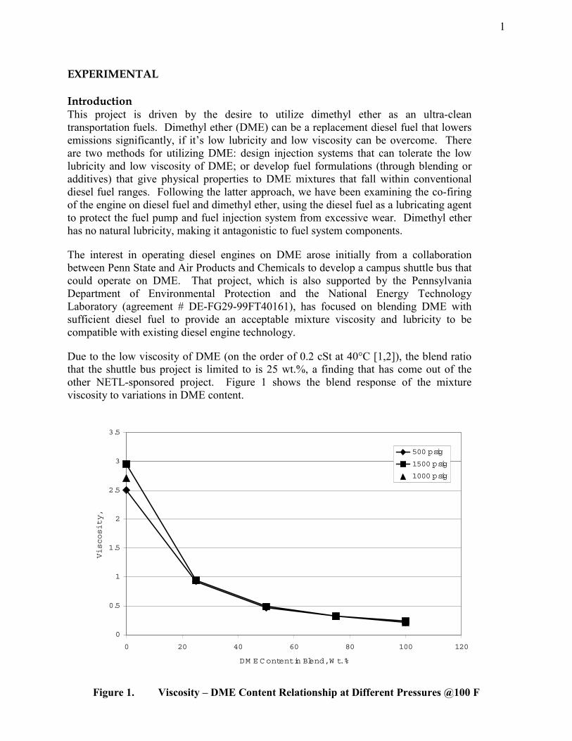
Due to the low viscosity of DME (on the order of 0.2 cSt at 40°C [1,2]), the blend ratio that the shuttle bus project is limited to is 25 wt.%, a finding that has come out of the other NETL-sponsored project. Figure 1 shows the blend response of the mixture viscosity to variations in DME content.
0
0.5
1
1.5
2
2.5
3
3.5
0 20 40 60 80 100 120
DM E C ontent in Blend, W t. %
Viscosity,
500 psig
1500 psig
1000 psig
Figure 1. Viscosity – DME Content Relationship at Different Pressures @100 F

2
As Figure 1 shows, at 25 wt.% DME the viscosity drops to roughly 1.39 cSt, which is the lower limit of the ASTM specification for diesel fuel viscosity. To increase the allowable DME without exposing the injectors to excessive wear and early failure, both the lubricity and the viscosity of the fuel blend must be kept within the ASTM specifications. To that end and to raise the allowable DME content in the mixture, the present work focuses in parallel on selection and development of additives to improve lubricity and viscosity of DME fuel blends.
In our laboratory engine, we have demonstrated effective operation on the 25 wt.% DME blended fuel. In the field, we successfully demonstrated the operation of a campus shuttle bus on blends of DME in diesel up to 25 wt.% DME [3]. Through collaboration with the Tribology Laboratory in Penn State’s Chemical Engineering Department, we are characterizing the viscosity, compressibility and miscibility of blends of DME, diesel fuel and the additives under pressures and temperatures relevant to the fuel injection system. These tests are using a high pressure viscometer adapted to these specific experiments. This instrument, combined with a high pressure cell for lubricity studies and an injector durability stand to demonstrate injector time-to-failure, provides us with the ability to determine if additives can be used to increase DME content in the blended fuel while not sacrificing injector lifetime.
At present, we have completed an initial screening of the impact on the viscosity of DME of various lubricity additives and high lubricity fuels. This work has results in a manuscript that was recently accepted for publication in Energy & Fuels, to appear in July 2003 []. In addition, we have modified an existing Cameron-Plint reciprocating wear test apparatus to investigate the lubricity of DME blends with diesel fuel and lubricity and viscosity improvers and are presently shaking down the modified apparatus. After failing to acquire a donation of an injector durability test stand, we are also working to develop our own inexpensive injector durability stand using students from senior design classes and hardware from the now completed DME Shuttle Bus project.
Caterpillar (manufacturer of the HEUI fuel injectors on the Navistar T444E turbodiesel engine) had agreed to participate in this project on injector durability and they have already provided 6 sets of HEUI injectors (8 injectors per set, total retail value of over $24,000) for this project. One set was installed in the DME Shuttle Bus to provide some field data on wear rates using DME diesel blends. The rest of the injectors will be used in the injector durability stand. Unfortunately, due to difficult financial time, Caterpillar was not able to follow through on the donation of a HEUI Endurance Stand for the injector durability studies. However, Caterpillar did complete a post mortem analysis of the fuel injectors that were operated for three months with DME blended fuel on the DME Shuttle Bus. Caterpillar found that the injectors had suffered some damage to their internal components, but could not explain how. This provides evidence that DME operation can lead to unexpected injector behavior, and confirms the need for the present project.

3
RESULTS AND DISCUSSION
This section of this report consists of sub-sections on each of the major activities (tasks) under the project.
Task 1. Wear Rate and Lubricity Measurements of DME-Diesel Fuel Blends
Task 2. Injector Durability Studies
Task 1. Wear Rate and Lubricity Measurements of DME-Diesel Fuel Blends Viscosity Measurements of Lubricity Improvers
(inserted below is the text of a paper that was recently accepted by Energy & Fuels on this subject)
Characterization of the Viscosity of Blends of Dimethyl Ether
with Various Fuels and Additives
Shirish Bhide, David Morris, Jonathan Leroux, Kimberly S. Wain, Joseph M. Perez and André L. Boehman*
The Energy Institute 405 Academic Activities Building The Pennsylvania State University
University Park, PA 16802 ABSTRACT Dimethyl ether (DME) is a potential ultra clean diesel fuel. Dimethyl ether burns without producing the smoke associated with diesel combustion and can be manufactured from synthesis gas or methanol. However, DME has a low viscosity compared to diesel fuel and has insufficient lubricity to prevent excessive wear in fuel injection systems. One strategy to utilize DME is to blend it with diesel fuel to obtain cleaner burning fuels that retain satisfactory fuel properties. In the present work, the viscosity of blends of DME and various fuels and additives was characterized, including a federal low sulfur diesel fuel, soybean oil, biodiesel and various lubricity additives, over a range of blend ratios. A methodology was developed to utilize a high pressure capillary viscometer to measure the viscosity of pure DME and blends of DME and other compounds in varying proportions and at pressures up to 3500 psig. While DME is miscible in diesel fuel at any mixture fraction when the blend is held under pressures of 75 psi or above, the viscosity of the blends is below the ASTM diesel fuel specification for even a 25 wt.% blend of DME in diesel fuel. None of the additives or fuels provides adequate viscosity when blended with DME unless the blend contains less than 50% DME. Viscosity, rather than lubricity, may be the limiting factor in utilizing DME.
* Corresponding Author: Ph: 814-865-7839, Fax: 814-863-8892, E-mail: [email protected]

4
INTRODUCTION
The need to reach ever tightening NOx and particulate emissions standards has placed a tremendous amount of pressure on fuel, lubricant, engine and vehicle manufacturers. However, in the 1990’s studies of direct injection diesel engines fueled by dimethyl ether (DME) demonstrated particulate emissions below the ULEV standard and NOx emissions that approach or achieve ULEV levels, without exhaust aftertreatment [1,2]. As a consequence, DME is gaining increasing interest for use in compression ignition (CI) engines as a replacement diesel fuel. Until those tests, DME had not been considered as a primary replacement fuel. Previously, DME had been considered as a methanol ignition improver for methanol powered vehicles [3,4,5,6]. At present, the predominant use for DME is as an environmentally benign aerosol propellant, since DME is non-toxic and is easily degraded in the troposphere [7]. Recent work on DME has focused on its use in advanced technology, direct-injection (DI) engines as a neat fuel [8,9,10,11,12]. Due to the presence of an oxygen atom in DME’s molecular structure, the absence of a carbon-carbon bond and its high cetane number, the DME-fueled engine appears to circumvent the traditional tradeoff between oxides of nitrogen (NOx) and particulates that plagues the CI engine running on diesel fuel. The high cetane number of DME also helps in reducing combustion noise, which is another drawback of the diesel fuel fired CI engine [1,2,13,14,15,16,17] DME is the simplest ether compound (chemical formula C2H6O). Some physical and chemical characteristics of DME are given in Table 1. At standard temperature and pressure it is a gas, but can be liquefied under a moderate pressure. This makes DME quite similar to propane and liquefied petroleum gas for handling purposes. DME was first used as an aerosol propellant because of its environmentally benign characteristics. It is not harmful to the ozone layer , unlike the CFCs that it replaced. DuPont Fluorochemicals provides a technical information bulletin [18] that gives a good overview of the physical and chemical properties of DME. Table 1: Physical and Chemical Properties of DME [18] Chemical formula H3C-O-CH3 Molecular weight 46.07 Oxygen content by mass 34.8 % CAS Registry number 115-10-6 Boiling point @ 1 atmosphere -24.825 °C Critical temperature 126.85 °C Critical pressure 5370 kPa Liquid density @ 25 °C 656.62 kg/m3 Vapor pressure @ 20 °C 516.76 kPa Flammability limits in air by volume % 3.4 – 18 A high cetane number makes DME an attractive fuel for compression ignition (CI) engines. However, DME has significantly different physical properties than diesel fuel

5
including a low critical point, low viscosity, negligible lubricity and a high vapor pressure. As DME has a high vapor pressure, the fuel system needs to be pressurized to maintain DME in a liquid state. Moreover, the fuel system has to be modified considering the chemical properties of DME, such as its incompatibility with many elastomers. In the present work, DME has been blended into diesel fuel to obtain a fuel mixture that retains the desirable physical properties of diesel fuel but includes the cleaner burning capability of DME. The miscibility and viscosity of blends of DME and diesel fuel were characterized using pressurized, optically accessible instrumentation. These physical property measurements are part of a comprehensive study of the operation of a turbodiesel engine on DME-diesel blends which led to a field demonstration of this fueling strategy [19,20,21]. In the culmination of the demonstration, a campus shuttle bus was operated on blends of DME and diesel fuel on a shuttle route at the University Park campus of the Pennsylvania State University in the first operation of an in-service transit vehicle on DME anywhere in the world [21]. Diesel fuel injection systems are designed for diesel fuel, which has a kinematic viscosity an order of magnitude higher than that of pure DME, as evidenced by the ASTM standards for diesel fuel properties [22]. In this paper, the viscosity of DME in blends with various fuels and additives is examined to determine whether the mixture viscosity can be improved via blending or additization. These viscosity measurements are among the first reported for DME under elevated pressures and are the first reported for blends in diesel fuel. Recent work by Sivebaek et al. [23] also considered the viscosity of DME, in particular with addition of lubricity and viscosity enhancing additives. They developed a volatile fuel viscometer (VFVM) that was designed to handle DME, neat or additized. They measured kinematic and dynamic viscosities of pure DME of 0.185 cSt and 0.122 cP at 25 °C, which as will be shown, compares well with the present study. Their measurements were performed at 5 bar pressure, roughly 75 psi. They concluded that additized DME cannot reach the same viscosity and lubricity as diesel fuel. They suggest that rather than using additives to allow fuel systems to tolerate DME, the solution is to design fuel injection hardware to handle pure DME. McCandless and co-workers have developed models for the properties of DME and have developed fuel injection systems to accommodate neat DME (or more specifically, DME with 1% of a castor oil additive) [11,24]. Their approach has been to develop systems with less of the sliding wear that leads to pump and injector failures that were observed in earlier work on DME. In contrast, the work presented here involves accommodating DME within existing, commercial fuel injection systems. Thus, there is a need to determine how to improve the viscosity of DME fuel blends, while keeping the DME content as high as possible to capture the emissions benefits of DME. To that end, this paper presents viscosity measurements of DME blended with various fuels and with various lubricity enhancing additives, to assess whether the viscosity of DME can be increased with only modest treat rates of other substances. The work presented here is the product of a joint effort by
6
the Penn State Energy Institute and Multi-discipline Tribology Group, which have collaborated on studies of several alternative fuels including biodiesel fuels [25] and oxygenated fuels [26]. Significant improvements in friction and wear were demonstrated by vapor-phase oxidation of biodiesel fuels [27]. EXPERIMENTAL
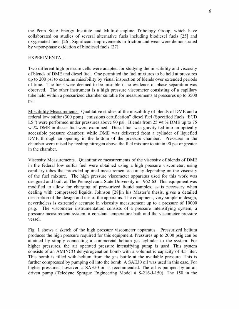
Two different high pressure cells were adapted for studying the miscibility and viscosity of blends of DME and diesel fuel. One permitted the fuel mixtures to be held at pressures up to 200 psi to examine miscibility by visual inspection of blends over extended periods of time. The fuels were deemed to be miscible if no evidence of phase separation was observed. The other instrument is a high pressure viscometer consisting of a capillary tube held within a pressurized chamber suitable for measurements at pressures up to 3500 psi. Miscibility Measurements. Qualitative studies of the miscibility of blends of DME and a federal low sulfur (300 ppm) “emissions certification” diesel fuel (Specified Fuels “ECD LS”) were performed under pressures above 90 psi. Blends from 25 wt.% DME up to 75 wt.% DME in diesel fuel were examined. Diesel fuel was gravity fed into an optically accessible pressure chamber, while DME was delivered from a cylinder of liquefied DME through an opening in the bottom of the pressure chamber. Pressures in the chamber were raised by feeding nitrogen above the fuel mixture to attain 90 psi or greater in the chamber. Viscosity Measurements. Quantitative measurements of the viscosity of blends of DME in the federal low sulfur fuel were obtained using a high pressure viscometer, using capillary tubes that provided optimal measurement accuracy depending on the viscosity of the fuel mixture. The high pressure viscometer apparatus used for this work was designed and built at The Pennsylvania State University in 1962-63. This equipment was modified to allow for charging of pressurized liquid samples, as is necessary when dealing with compressed liquids. Johnson [28]in his Master’s thesis, gives a detailed description of the design and use of the apparatus. The equipment, very simple in design, nevertheless is extremely accurate in viscosity measurement up to a pressure of 10000 psig. The viscometer instrumentation consists of a pressure intensifying system, a pressure measurement system, a constant temperature bath and the viscometer pressure vessel. Fig. 1 shows a sketch of the high pressure viscometer apparatus. Pressurized helium produces the high pressure required for this equipment. Pressures up to 2000 psig can be attained by simply connecting a commercial helium gas cylinder to the system. For higher pressures, the air operated pressure intensifying pump is used. This system consists of an AMINCO dehydrogenation bomb with a volumetric capacity of 4.5 liter. This bomb is filled with helium from the gas bottle at the available pressure. This is further compressed by pumping oil into the bomb. A SAE30 oil was used in this case. For higher pressures, however, a SAE50 oil is recommended. The oil is pumped by an air driven pump (Teledyne Sprague Engineering Model # S-216-J-150). The 150 in the

7
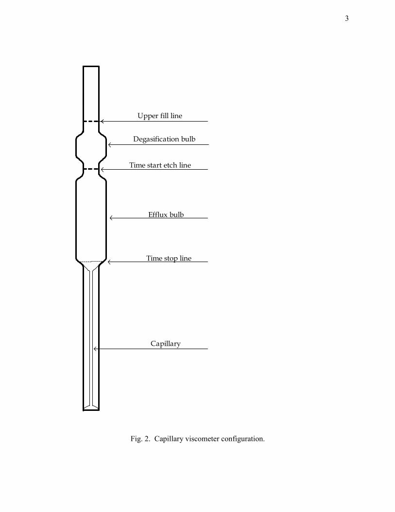
model number indicates the factor by which the pressure of oil can be raised as compared to the pressure of the supplied driver air. High pressure gauges are used to measure the pressure in the system. These gauges have a maximum readability of 5000 and 10000 psig and have a rated accuracy of 0.5% of full scale. For the present study, the gauge with a capacity of 5000 psig was used for its higher resolution. For the present study, the viscometer housing was kept at a constant temperature of 100°F (38°C) in a water bath. Prior to beginning the viscosity measurement, the sample is prepared in the sample cylinder and maintained at a pressure of about 500 psig. The sample cylinder is then kept in the water bath overnight to ensure thermal equilibrium between the sample and the water bath. The AMINCO hydrogenation bomb is charged to the required pressure by operating the pressurizing equipment. The viscometer capillary is assembled in the pressure vessel and is brought up to the operating pressures. The following steps are then taken to charge the viscometer capillary with the fluid and measure its viscosity. Samples of fuels or blends are prepared in a sample cylinder. The sample cylinder is connected to the viscometer housing, pressure is allowed to equilibrate between the sample cylinder and the viscometer housing, and sample is introduced into the capillary tube. The level of the sample is observed through the glass windows on the viscometer housing. Then, the viscometer is allowed to reach thermal equilibrium between the capillary, housing and sample. The measurement of viscosity is performed by measuring the time required to drain fluid from the capillary, as the meniscus in the capillary falls past two etched lines on the capillary. Fig. 2 shows the locations of the etchings and the configuration of the capillary tube. The time is measured with a resolution of 0.01 seconds. The measured efflux time along with the characteristic distance are the only two observations required of the viscosity test. The characteristic distance is the distance between the liquid level at the bottom of the viscometer housing and the bottommost etched line on the capillary. This distance is measured by a cathetometer with a resolution of 0.005 cm. The procedure followed for calibration of the viscometer is the same as that followed for viscosity measurement. The calibration is performed by allowing a liquid with a known viscosity to drain from the capillary. A series of runs are performed by varying the characteristic height. For every run, the characteristic height and drainage time are recorded. A viscometer constant is calculated via Equation 1: viscometer constant (s/cSt) = drainage time (s)/ viscosity of calibration liquid (cSt) (1) Fuel and Additive Samples. The DME was obtained from DuPont Fluorochemicals and is highly purified, having less than 20 ppm water content. The diesel fuel is a federal low sulfur fuel, emissions certification diesel fuel from Specified Fuels (ECD-LS). The biodiesel fuel was obtained from World Energy as 100% biodiesel (B100 “Envirodiesel’). Lubricity additives were obtained from Lubrizol Corporation (539N) and Ethyl Petroleum Additives, Inc. (“HiTEC Performance Additives” 4140 and 580, referred to here as H4140 and H580). The soybean oil was provided by Agricultural Commodities, Inc. and was produced from soybeans through a heated extrusion and press process. The

8
viscosity of these fuels and additives are presented in Table 2, along with some other physical and chemical property information.
Table 2. Viscosity of fuels and additives
ASTM Method
ASTM Spec.
Base Diesel
DME
(75 psi)
Biodiesel (B100)
Soybean Oil
Ethyl H4140
Ethyl H580
Lubrizol 539N
Viscosity, 40°C, cSt
D 445 [29]
1.39-4.20
2.5 0.185 4.1 31.3 17 110 31.4 (@25°C)
Viscosity, 100°C, cSt
1.1 1.7 7.6
RESULTS AND DISCUSSION
Miscibility Measurements. The DME was observed to rapidly mix uniformly with the diesel fuel at all blend ratios. Over time, a blend that was initially not well mixed would become uniform, but injection of the DME from below the pool of diesel fuel was a particularly effective means of rapidly obtaining a uniform mixture. The biodiesel and soybean oil samples and the lubricity additives mixed uniformly with DME and remained mixed over time, at the concentrations examined here. Viscosity Measurements. Observations of the viscosity of the blends of DME and diesel fuel are summarized in Fig. 3. Measurements were obtained over a range of pressures with the viscometer housing immersed in a constant temperature bath at 100°F (38°C). Results obtained at three different levels of chamber pressure are plotted in Fig. 4 to show the impact of DME content on viscosity. These two figures show that the viscosity of diesel fuel decreases rapidly at low levels of DME addition. For instance at 25 wt.% DME addition, viscosity falls by more than a factor of 2, from the more than 2.5 cSt value of the neat diesel fuel to roughly 1 cSt. This non-linear blending response demonstrates that even modest addition of DME to diesel fuel brings the fuel blend below the ASTM diesel viscosity specification of 1.39-4.20 cSt at 40°C [22]. This result is predicted using the ASTM oil blending calculations method D 341 [30]. According to this method, oils blend in a logarithmic fashion, allowing a small amount of a low viscosity component to have a large effect on blend viscosity. Predicted blend viscosities, shown in Fig. 4, match the experimentally observed trends. These viscosity measurements are among the first reported for DME under elevated pressures and are the first reported for blends in diesel fuel. Sivebaek et al. [23] considered the viscosity of DME, in particular with addition of lubricity and viscosity enhancing additives, using a volatile fuel viscometer (VFVM). They measured kinematic and dynamic viscosities of pure DME of 0.185 cSt and 0.122 cP at 25 °C, respectively. Their measurements were performed at 5 bar pressure, roughly 75 psi. In the present study, no DME blends were examined at a pressure below 500 psi, but at 500 psi pressure
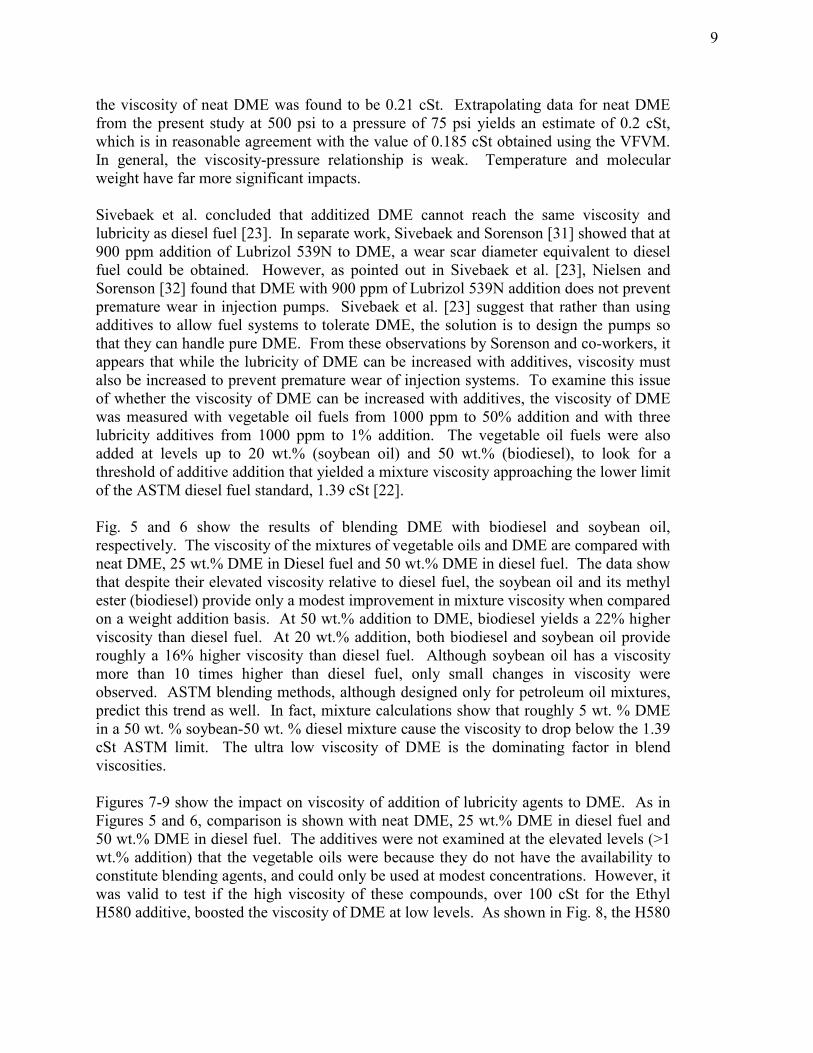
9
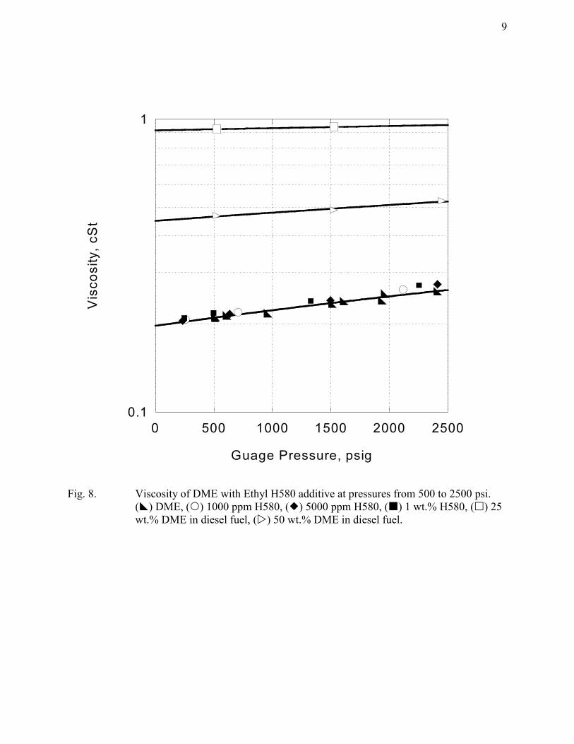
the viscosity of neat DME was found to be 0.21 cSt. Extrapolating data for neat DME from the present study at 500 psi to a pressure of 75 psi yields an estimate of 0.2 cSt, which is in reasonable agreement with the value of 0.185 cSt obtained using the VFVM. In general, the viscosity-pressure relationship is weak. Temperature and molecular weight have far more significant impacts. Sivebaek et al. concluded that additized DME cannot reach the same viscosity and lubricity as diesel fuel [23]. In separate work, Sivebaek and Sorenson [31] showed that at 900 ppm addition of Lubrizol 539N to DME, a wear scar diameter equivalent to diesel fuel could be obtained. However, as pointed out in Sivebaek et al. [23], Nielsen and Sorenson [32] found that DME with 900 ppm of Lubrizol 539N addition does not prevent premature wear in injection pumps. Sivebaek et al. [23] suggest that rather than using additives to allow fuel systems to tolerate DME, the solution is to design the pumps so that they can handle pure DME. From these observations by Sorenson and co-workers, it appears that while the lubricity of DME can be increased with additives, viscosity must also be increased to prevent premature wear of injection systems. To examine this issue of whether the viscosity of DME can be increased with additives, the viscosity of DME was measured with vegetable oil fuels from 1000 ppm to 50% addition and with three lubricity additives from 1000 ppm to 1% addition. The vegetable oil fuels were also added at levels up to 20 wt.% (soybean oil) and 50 wt.% (biodiesel), to look for a threshold of additive addition that yielded a mixture viscosity approaching the lower limit of the ASTM diesel fuel standard, 1.39 cSt [22]. Fig. 5 and 6 show the results of blending DME with biodiesel and soybean oil, respectively. The viscosity of the mixtures of vegetable oils and DME are compared with neat DME, 25 wt.% DME in Diesel fuel and 50 wt.% DME in diesel fuel. The data show that despite their elevated viscosity relative to diesel fuel, the soybean oil and its methyl ester (biodiesel) provide only a modest improvement in mixture viscosity when compared on a weight addition basis. At 50 wt.% addition to DME, biodiesel yields a 22% higher viscosity than diesel fuel. At 20 wt.% addition, both biodiesel and soybean oil provide roughly a 16% higher viscosity than diesel fuel. Although soybean oil has a viscosity more than 10 times higher than diesel fuel, only small changes in viscosity were observed. ASTM blending methods, although designed only for petroleum oil mixtures, predict this trend as well. In fact, mixture calculations show that roughly 5 wt. % DME in a 50 wt. % soybean-50 wt. % diesel mixture cause the viscosity to drop below the 1.39 cSt ASTM limit. The ultra low viscosity of DME is the dominating factor in blend viscosities. Figures 7-9 show the impact on viscosity of addition of lubricity agents to DME. As in Figures 5 and 6, comparison is shown with neat DME, 25 wt.% DME in diesel fuel and 50 wt.% DME in diesel fuel. The additives were not examined at the elevated levels (>1 wt.% addition) that the vegetable oils were because they do not have the availability to constitute blending agents, and could only be used at modest concentrations. However, it was valid to test if the high viscosity of these compounds, over 100 cSt for the Ethyl H580 additive, boosted the viscosity of DME at low levels. As shown in Fig. 8, the H580

10
additive provided only a 5% increase in viscosity at 1 wt.% addition. Similarly weak results were obtained with the Ethyl H4140 and Lubrizol 539N additives. Unlike diesel fuel molecules, DME does not contain any long chain components, limiting additive-fuel interaction. Typically the C12-C24 chains of diesel will entangle with viscosity improving molecules, increasing the mixture viscosity. DME also allows little or no hydrogen bonding to occur. The solution to proper lubrication of injection system components may lie not in the ability to increase the viscosity of DME up to ATSM standards, but in the ability of additives to form a protective surface film on the wearing metal components. Typically these types of additives are polar in nature and potentially contain aromatic rings and/or double bonds to enhance molecular interactions. This increases the potential for physical or chemical adsorption to metal surfaces. In viscosity improvers, polymer molecules “swell” in the presence of fuel. The volume of the swollen mixture dictates the degree of viscosity improvement. A protective surface film would not be subject to this swelling mechanism and may therefore improve lubricity via another method. Thus, it is clear from the present work and the previous studies by Sivebaek et al. that lubricity agents do not provide effective means of boosting the viscosity of DME at treat rates that are relevant for additives. However, plant oil-derived fuels such as soybean oil, biodiesel (soybean oil methyl ester), rapeseed oil and rapeseed oil methyl ester (RME) can provide both improvement in viscosity at high treat rates and, as shown by Sivebaek et al., at low levels can provide adequate lubricity. What must also be considered in any attempt to formulate a fuel grade DME that possesses diesel-like fluid properties is the practicality and availability of additives and blending agents. Plant oil-derived fuels may need to be blended at rather high levels to provide an adequate boost to the viscosity of DME, but they are commercially available on sufficiently large scale to be practical. Other additives may not be available in quantities that are sufficient to permit production of fuel grade DME. What remains is a need to engineer solutions that provide a large improvement to the viscosity of DME at levels typical of fuel additives, not fuel blending stocks, but that can be produced in sufficiently large volume.
CONCLUSIONS
Blending DME in diesel fuel is one option to utilize DME in diesel engines without drastic redesign of fuel pumps and fuel injectors. However, even modest addition of DME into diesel fuel significantly reduces the viscosity of the fuel mixture. Addition of as little as 25 wt.% DME into diesel fuel reduces fuel viscosity below the ASTM specification. This suggests that viscosity rather than miscibility is the limiting factor in blending DME with diesel fuel. Examination of other, more viscous substances, blended with DME showed that additization alone is unlikely to accomplish the goal of raising the viscosity of DME to the level of conventional fuels. Neither vegetable oil fuels or lubricity additives increased the level of fuel viscosity to that of diesel fuel without blending at levels above 50 wt.% in DME. Therefore, either new compounds specifically designed to provide a viscosity improvement must be formulated, or fuel blending will be

11
required to achieve diesel-like fluid properties. Lubricity may be enhanced through the use of surface film forming additives.
ACKNOWLEGDMENT
The authors wish to acknowledge the support of Air Products and Chemicals, Inc., Caterpillar, Inc., Ethyl Additives, Inc., the Pennsylvania Department of Environmental Protection and the National Energy Technology Laboratory of the U.S. Department of Energy. In particular, the authors wish to acknowledge the support and encouragement of John Winslow, Mike Nowak and Jenny Tennant of NETL and Barry Halper, Jo Ann Franks and Jim Sorensen of Air Products, and especially Peter J.A. Tijm (formerly of Air Products). The authors wish to thank and acknowledge donation of additives for use in this project by Ethyl Additives, Inc. and Lubrizol, Inc. Also, the authors wish to thank Elana Chapman for directing the selection of additives considered in this work and for her collaboration on the project. This paper was written with support of the US Department of Energy under Contract no. DE-FG29-99FT40161 and Cooperative Agreement DE-FC26-01NT41115. The Government reserves for itself and others acting on its behalf a royalty-free, nonexclusive, irrevocable, worldwide license for Governmental purposes to publish, distribute, translate, duplicate, exhibit and perform this copyrighted paper. This material was prepared with the support of the Pennsylvania Department of Environmental Protection. Any opinions, findings, conclusions, or recommendations expressed herein are those of the author(s) and do not necessarily reflect the views of the DEP.

12
REFERENCES [1] Fleisch, T., McCarthy, C., Basu, A., Udovich, C., Charbonneau, P., Slodowske, W.,
Mikkelson, S.-E., and McCandless, J., “A New Clean Diesel Technology: Demonstration of ULEV Emissions on a Navistar Diesel Engine Fueled with Dimethyl Ether,” 1995, Society of Automotive Engineers Technical Paper No. 950061.
[2] Kapus, P. E., and Cartellieri, W. P., “ULEV Potential of a DI/TCI Diesel Passenger Car Engine Operated on Dimethyl Ether,” 1995, Society of Automotive Engineers Technical Paper No. 952754.
[3] Karpuk, M. E. and Cowley, S. W., “On Board Dimethyl Ether Generation to Assist Methanol Engine Cold Starting,” 1988, Society of Automotive Engineers Technical Paper No. 881678.
[4] Green, C. J., Cockshutt, N. A. and King, L., “Dimethyl Ether as a Methanol Ignition Improver: Substitution Requirements and Exhaust Emissions Impact,” 1990, Society of Automotive Engineers Technical Paper No. 902155.
[5] Murayama, T., Chikahisa, T., Guo, J., and Miyano, M., “A Study of a Compression Ignition Methanol Engine with Converted Dimethyl Ether as an Ignition Improver,” 1992, Society of Automotive Engineers Technical Paper No. 922212.
[6] Guo, J., Chikahisa, T., Murayama, T., and Miyano, M., “Improvement of Performance and Emissions of a Compression Ignition Methanol Engine with Dimethyl Ether,” 1994, Society of Automotive Engineers Technical Paper No. 941908.
[7] Hansen, J. B., Voss, B., Joensen, F., and Siguroardottir, I. D., “Large Scale Manufacture of Dimethyl Ether – a New Alternative Diesel Fuel from Natural Gas,” 1995, Society of Automotive Engineers Technical Paper No. 950063.
[8] Wilson, R., “DME Shows Promise as Drop-In ‘Replacement’ for Diesel Fuel; Tests Meet CARB 1998 ULEV Standards,” 1995, Diesel Progress Engines and Drives, June 1995, pp. 108-109.
[9] Fleisch, T. H., “More on Dimethyl Ether: Case is Building for DME as Clean Diesel Fuel,” Diesel Progress Engines and Drives, 1995, October 1995, pp. 42-45.
[10] Glensvig, M., Sorenson, S. C. and Abata, D. L., “An Investigation of the Injection Characteristics of Dimethyl Ether,” 1997, ASME Paper No. 97-ICE-67, ICE-Vol. 29-3, pp. 77-84.
[11] McCandless, J. C. and Li, S., “Development of a Novel Fuel Injection System (NFIS) for Dimethyl Ether – and Other Clean Alternative Fuels,” 1997, Society of Automotive Engineers Technical Paper No. 970220.
[12] Alam, M., Fujita, O., Ito, K., Kajitani, S., Oguma, M. and Machida, H., “Performance of NOx Catalyst in a DI Diesel Engine Operated with Neat Dimethyl Ether,” 1999, Society of Automotive Engineers Technical Paper No. 1999-01-3599.
[13] Sorenson, S. C., and Mikkelsen, S.-V., “Performance and Emissions of a 0.273 Liter Direct Injection Diesel Engine Fuelled with Neat Dimethyl Ether,” 1995, Society of Automotive Engineers Technical Paper No. 950064.
[14] Kapus, P. and Ofner, H., “Development of Fuel Injection Equipment and Combustion System for DI Diesels Operated on Dimethyl Ether,” 1995, Society of Automotive Engineers Technical Paper No. 950062.

13
[15] Longbao, Z., Hewu, W., Deming, J., Zuohua, H., “Study of Performance and
Combustion Characteristics of a Dme- Fueled, Light-Duty, Direct-Injection Diesel Engine,” 1999, Society of Automotive Engineers Technical Paper No. 1999-01-3669.
[16] Kajitani, S., Chen, Z.L., Konno, M., Rhee, K.T., “Engine Performance and Exhaust Characteristics of Direct Injection Diesel Engine Operated with DME” 1997, Society of Automotive Engineers Technical Paper No. 972973.
[17] Christensen, R., Sorenson, S.C., Jensen, M.G., Hansen, K.F., “Engine Operation on Dimethyl Ether in a Naturally Aspirated IDI Diesel Engine,” 1997, Society of Automotive Engineers Technical Paper No. 971665.
[18] DuPont Fluorochemicals, “DuPont Dymel®A Aerosol Propellants, Fluorochemicals Laboratory,” E. I. duPont de Nemours and Company, ATB-25, www.dupont.com/dymel.
[19] Chapman, E. M, Bhide, S. V., Boehman, A. L., Tijm, P. J. A. and Waller, F. J., “Emission Characteristics of a Navistar 7.3L Turbodiesel Fueled with Blends of Oxygenates and Diesel,” 2000, Society of Automotive Engineers Technical Paper No. 2000-01-2887.
[20] Chapman, E.M., Boehman, A.L., Tijm, P.J.A. and Waller, F.J., “Emission Characteristics of a Navistar 7.3L Turbodiesel Fueled with Blends of Dimethyl Ether and Diesel Fuel,” 2001, Society of Automotive Engineers Technical Paper No. 2001-01-3626.
[21] Eirich, J., Chapman, E., Glunt, H., Klinikowski, D., Boehman, A. L., Hansel, J. G. and Heydorn, E. C., “Development of a Dimethyl Ether (DME)-Fueled Shuttle Bus,” 2003, Society of Automotive Engineers Technical Paper No. 2003-01-0756.
[22] American Society for Testing of Materials, “D975-98b Standard Specification for Diesel Fuel Oils”, 2000 Annual Book of ASTM Standards: Petroleum Products, Lubricants, and Fossil Fuels, Volume 05.01, West Conshohocken, PA (2000).
[23] Sivebaek, I. M., Sorenson, S. C., and Jakobsen, J., “Dimethyl Ether (DME) – Assessment of Viscosity Using the New Volatile Fuel Viscometer (VFVM),” 2001, Society of Automotive Engineers Technical Paper No. 2001-01-2013.
[24] Teng, H., McCandless, J. C., and Schneyer, J. B., “Thermochemical Characteristics of Dimethyl Ether – An Alternative Fuel for Compression-Ignition Engines,” 2001, Society of Automotive Engineers Technical Paper No. 2001-01-0154.
[25] Kershner, D., Morris, D., Boehman, A., Perez, J. M., and Sharer, D., “Investigation of Raw Soy Oil as a Diesel Fuel Extender” Proceedings, AOCS International Meeting, Istanbul, Turkey, May 2002.
[26] Song, J., K. Cheenkakorn, J. Wang, J. Perez, A.L. Boehman, P.J. Young and F.J. Waller. “Effect of Oxygenated Fuel on Combustion and Emissions in a Light-Duty Turbo Diesel Engine,” 2002, Energy & Fuels, 16, 294-301.
[27] Wain, K.S., and Perez, J.M., “Oxidation of Biodiesel Fuels for Improved Lubricity”, 2002, ASME 2002-ICE-447, ICE-Vol. 38, pp. 27-34.
[28] Johnson, R.H., “Design and Use of a Precision Pressure Viscometer,” 1962, M.S. Thesis, The Pennsylvania State University, University Park, PA.
[29] American Society for Testing of Materials, “D445-97 Standard Test Method for Kinematic Viscosity of Transparent and Opaque Liquids (the Calculation of

14
Dynamic Viscosity)”, 2000 Annual Book of ASTM Standards: Petroleum Products, Lubricants, and Fossil Fuels, Volume 05.01, West Conshohocken, PA (2000).
[30] American Society for Testing of Materials, “D341-93(1998) Standard Viscosity-Temperature Charts for Liquid Petroleum Products”, 2000 Annual Book of ASTM Standards: Petroleum Products, Lubricants, and Fossil Fuels, Volume 05.01, West Conshohocken, PA (2000).
[31] Sivebaek, I.M. and Sorenson, S.C., “Dimethyl Ether (DME) – Assessment of Lubricity Using the Medium Frequency Pressurised Reciprocating Rig Version 2 (MFPRR2),” 2000, Society of Automotive Engineers Paper No. 2000-01-2970.
[32] Nielsen, K. and Sorenson, S.C., “Lubricity Additives and Wear with DME in Diesel Injection Pumps,” 1999, ASME Paper 99-ICE-217, ICE-Vol. 33-1, pp. 145-153.
1
LIST OF FIGURES Fig. 1. High pressure viscometer configuration Fig. 2. Capillary viscometer configuration. Fig. 3. Viscosity of DME-diesel blends at pressures from 500 to 2500 psi. ( ) diesel fuel, ( )
DME, ( ) 25 wt.% DME, ( ) 50 wt.% DME, ( ) 75 wt.% DME.
Fig. 4. Blend response of viscosity to DME addition at various pressures. ( ) 500 psi, ( ) 1000 psi, ( ) 1500 psi, (─) ASTM D 341 blend prediction.
Fig. 5. Viscosity of DME-Biodiesel blends at pressures from 500 to 2500 psi. ( ) DME, ( ) 1000 ppm Biodiesel, ( ) 5000 ppm biodiesel, ( ) 1 wt.% Biodiesel, ( ) 5 wt.% Biodiesel, ( ) 20 wt.% Biodiesel, ( ) 50 wt.% Biodiesel, ( ) 25 wt.% DME in diesel fuel, ( ) 50 wt.% DME in diesel fuel.
Fig. 6. Viscosity of DME-Soybean Oil blends at pressures from 500 to 2500 psi. ( ) DME, ( )
1000 ppm soybean oil, ( ) 5000 ppm soybean oil, ( ) 1 wt.% soybean oil, ( ) 5 wt.% soybean oil, ( ) 20 wt.% soybean oil, ( ) 25 wt.% DME in diesel fuel, ( ) 50 wt.% DME in diesel fuel.
Fig. 7. Viscosity of DME with Ethyl H4140 additive at pressures from 500 to 2500 psi. ( )
DME, ( ) 1000 ppm H4140, ( ) 5000 ppm H4140, ( ) 1 wt.% H4140, ( ) 25 wt.% DME in diesel fuel, ( ) 50 wt.% DME in diesel fuel.
Fig. 8. Viscosity of DME with Ethyl H580 additive at pressures from 500 to 2500 psi. ( )
DME, ( ) 1000 ppm H580, ( ) 5000 ppm H580, ( ) 1 wt.% H580, ( ) 25 wt.% DME in diesel fuel, ( ) 50 wt.% DME in diesel fuel.
Fig. 9. Viscosity of DME with Lubrizol 539N additive at pressures from 500 to 2500 psi. ( )
DME, ( ) 1000 ppm 539N, ( ) 5000 ppm 539N, ( ) 1 wt.% 539N, ( ) 25 wt.% DME in diesel fuel, ( ) 50 wt.% DME in diesel fuel.

2
Con
stan
t Tem
pera
ture
Bat
hA
MIN
CO
Hyd
roge
natio
nBo
mb
Com
pres
sed
Hel
ium
Oil
Res
ervo
ir
Reg
ulat
edA
ir S
uppl
y
Vis
com
eter
pres
sure
ves
sel
Sam
ple
cylin
der
Air
Dri
ven
Pres
sure
Inte
nsifi
er
1000
0 ps
ig50
00 p
sig
Pres
sure
Mea
sure
men
tSy
stem
Pres
sure
gaug
e
1
23 4
5
6
7
89
1011
12
13
14
B
A
Fig. 1. High pressure viscometer configuration
3
Upper fill line
Degasification bulb
Time start etch line
Efflux bulb
Time stop line
Capillary
Fig. 2. Capillary viscometer configuration.

4
0.1
1
10
0 500 1000 1500 2000 2500
Vis
cosi
ty, c
St
Gauge Pressure, psig
Fig. 3. Viscosity of DME-diesel blends at pressures from 500 to 2500 psi. ( ) diesel fuel, ( )
DME, ( ) 25 wt.% DME, ( ) 50 wt.% DME, ( ) 75 wt.% DME.

5
0
1
2
3
4
5
0 20 40 60 80 100
Vis
cosi
ty, c
St
DME Content in Blend, wt.%
ASTM Limits
Fig. 4. Blend response of viscosity to DME addition at various pressures. ( ) 500 psi,
( ) 1000 psi, ( ) 1500 psi, (─) ASTM D 341 blend prediction.

6
0.1
1
0 500 1000 1500 2000 2500 3000
Vis
cosi
ty, c
St
Guage Pressure, psig
Fig. 5. Viscosity of DME-Biodiesel blends at pressures from 500 to 2500 psi. ( ) DME,
( ) 1000 ppm Biodiesel, ( ) 5000 ppm biodiesel, ( ) 1 wt.% Biodiesel, ( ) 5 wt.% Biodiesel, ( ) 20 wt.% Biodiesel, ( ) 50 wt.% Biodiesel, ( ) 25 wt.% DME in diesel fuel, ( ) 50 wt.% DME in diesel fuel.

7
0.1
1
0 500 1000 1500 2000 2500
Vis
cosi
ty, c
St
Guage Pressure, psig
Fig. 6. Viscosity of DME-Soybean Oil blends at pressures from 500 to 2500 psi. ( )
DME, ( ) 1000 ppm soybean oil, ( ) 5000 ppm soybean oil, ( ) 1 wt.% soybean oil, ( ) 5 wt.% soybean oil, ( ) 20 wt.% soybean oil, ( ) 25 wt.% DME in diesel fuel, ( ) 50 wt.% DME in diesel fuel.

8
0.1
1
0 500 1000 1500 2000 2500
Vis
cosi
ty, c
St
Guage Pressure, psig
Fig. 7. Viscosity of DME with Ethyl H4140 additive at pressures from 500 to 2500 psi.
( ) DME, ( ) 1000 ppm H4140, ( ) 5000 ppm H4140, ( ) 1 wt.% H4140, ( ) 25 wt.% DME in diesel fuel, ( ) 50 wt.% DME in diesel fuel.
9
0.1
1
0 500 1000 1500 2000 2500
Vis
cosi
ty, c
St
Guage Pressure, psig
Fig. 8. Viscosity of DME with Ethyl H580 additive at pressures from 500 to 2500 psi.
( ) DME, ( ) 1000 ppm H580, ( ) 5000 ppm H580, ( ) 1 wt.% H580, ( ) 25 wt.% DME in diesel fuel, ( ) 50 wt.% DME in diesel fuel.

10
0.1
1
0 500 1000 1500 2000 2500
Vis
cosi
ty, c
St
Guage Pressure, psig
Fig. 9. Viscosity of DME with Lubrizol 539N additive at pressures from 500 to 2500 psi.
( ) DME, ( ) 1000 ppm 539N, ( ) 5000 ppm 539N, ( ) 1 wt.% 539N, ( ) 25 wt.% DME in diesel fuel, ( ) 50 wt.% DME in diesel fuel.
11
Development of a Wear and Lubricity Test Apparatus In this task, we are converting an existing instrument to studies of lubricity of fuels and additives so as to screen lubricity and viscosity improvers for DME fuel blends. The additives that show promise with then be tested in the fuel injector durability tests (Task 2) and subsequently could be tested in the laboratory engine or field vehicle. The major activity of the work in the first year of the project focused on design of a high pressure cell to permit reciprocating wear tests that are relevant to the operation of the HEUI fuel injectors and that permit examination of additives in DME fuel blends. Thus, the modified apparatus needs to be able to operate at a nominal pressure of 150 psig and the cause wear of components similar in composition and design to those within the HEUI injector. In the second year of the project, this portion of the activities faced several delays related to a move of the equipment to new laboratory space and renovation of the new lab space to accommodate the equipment.
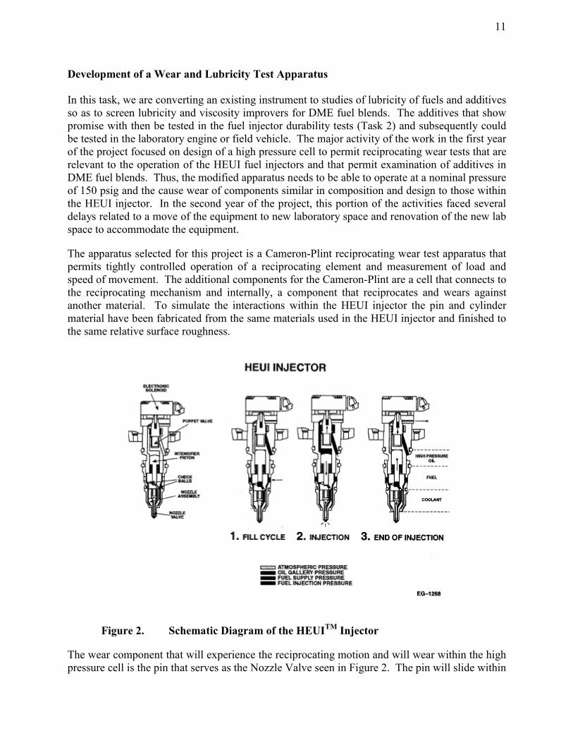
The apparatus selected for this project is a Cameron-Plint reciprocating wear test apparatus that permits tightly controlled operation of a reciprocating element and measurement of load and speed of movement. The additional components for the Cameron-Plint are a cell that connects to the reciprocating mechanism and internally, a component that reciprocates and wears against another material. To simulate the interactions within the HEUI injector the pin and cylinder material have been fabricated from the same materials used in the HEUI injector and finished to the same relative surface roughness.
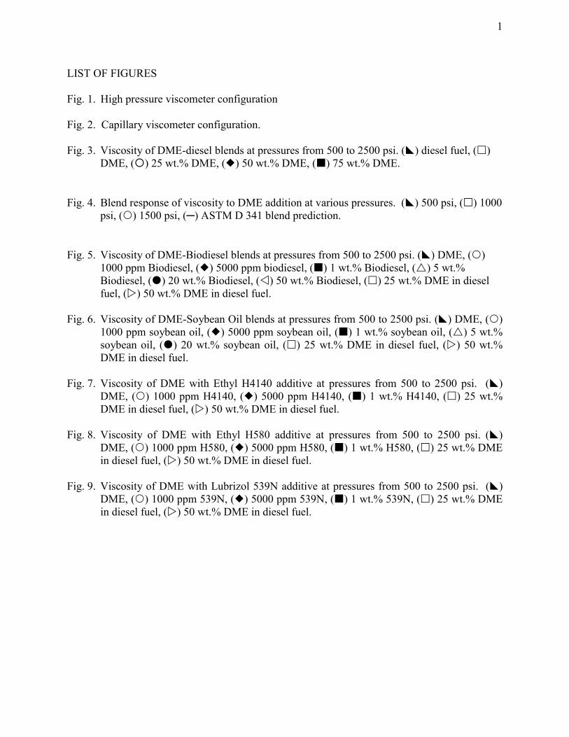
Figure 2. Schematic Diagram of the HEUITM Injector
The wear component that will experience the reciprocating motion and will wear within the high pressure cell is the pin that serves as the Nozzle Valve seen in Figure 2. The pin will slide within

12
a cylinder (or barrel) with a very tight tolerance. The wear mechanisms is likely a direct sliding wear between the pin and the cylinder (i.e., a scuffing wear) that is affected by the lubricating quality of the surrounding fluid (hydrodynamic lubrication) and the viscosity of the surrounding fluid (boundary layer lubrication).
The project goal is to determine how to effectively implement alternative diesel fuels into diesel engine systems. Among the fuels of interest, biodiesel and dimethyl ether (DME) are promising choices. Several obstacles remain before successful execution of these alternatives. These include meeting acceptable fuel injection durability parameters and optimizing the emissions and performance of a diesel engine.
Biodiesel is a vegetable oil derived diesel fuel with the distinct advantage of a renewable feedstock. Domestic crops can be converted into this eco-friendly fuel. Studies show that biodiesel/diesel blends are effective in reducing engine emissions. It is thought that the oxygen present in biodiesel molecules, which is not contained in ordinary diesel fuel, allows more complete combustion. The oxygen may also serve as a lubricity enhancer in the fuel system. This hypothesis needs to be tested and quantified.
Dimethyl Ether is also a viable renewable fuel alternative. This versatile chemical can be made from biomass via an industrial processing technique developed by Air Products. Early studies reported in 1995 demonstrated substantial emissions reductions with DME as a replacement diesel fuel. DME however is a gas at room temperature and pressure, resulting in a complicated set of adjustments to an engine. In initial tests reported in the literature, there was early failure of the fuel injection system. This is attributed to the fuel injection pressure exceeding the critical pressure of DME, resulting in the formation of a supercritical mixture of fuel and anti-wear additives. In the supercritical phase, additives may not be miscible with DME and no longer provide lubricity to the fuel. Another possibility is that the lubricity agent used in these earlier studies was ineffective or was not used at sufficient treat rates.
The most significant technical challenge while working with DME is accounting for the lubricating quality of the fuel and additive mixtures. This involves two considerations: (1) the lubricating quality of the components; and (2) the phase behavior of the mixtures, given that advanced diesel fuel injection systems use injection pressures that exceed the critical pressure of DME. In addition, there may be supercritical fluid behavior within the fuel injection systems, resulting in an increase in fuel compressibility, which may alter lubricity additive behavior.
The first step to determining operating parameters and engine adjustments is to build a bench top test stand for injector component wear studies. Such a device is outlined in the next section. In a simplified sense, the test is a pin and cylinder machined to fuel injector specifications moving in a concentric motion being lubricated by the fuel mixture of interest. The second step is to use the results of this test in a full fuel injector test stand. The test stand will include four injectors with proper temperature and pressure monitoring. Third, once acceptable levels of wear have been reached, the fuels can be tested in a stand-alone engine. Wear of fuel injection components will be used to judge the tolerance of the engine under actual operating conditions.

13
The end goal is to produce sufficient data to propose additives, fuel blends, engine adjustments and components that will take advantage of the potential of alternative fuels like DME. This will decrease emissions output and reduce the United State’s dependence on foreign energy supplies.
Bench Top Injection System Wear Test Stand The goal of this portion of the study is to define and solve lubricity problems associated with the use of alternative diesel fuels. There is a critical need to explore non-petroleum based fuels in order to reduce engine emissions and meet EPA and state restrictions. This work will allow evaluation of such fuels in an actual fuel injector environment, but at a significantly reduced cost than a full injector study, thereby reducing the potential for unforeseen wear during engine operation.
Biodiesel offers potential benefits compared to diesel. Initial tests show that biodiesel actually enhances the lubricity of diesel fuel. This may allow longer engine operation and reduce component wear. Blends of biodiesel and diesel would combine the benefits of enhanced lubricity and a renewable resource with the combustion efficiency and power output of diesel fuel. Dimethyl ether, as previously mentioned, exhibits poor publicity and therefore an additive study is necessary to enhance this aspect. To explore the possibilities, a fuel injector wear test is currently being fabricated.
The wear test design employs a traditional testing device known as a Cameron-Plint. This tool operates by reciprocating a pin on a flat surface, typically creating a sliding wear situation. The apparatus is capable of running under dry or lubricated conditions and at elevated temperatures. Modifications to this unit are necessary to mimic proper contact geometry and engine environment.
In order to alter the wear tester, the pin and flat plate assembly was removed. In its place a stainless steal housing with removable front and back plates was designed. Included at the end of this document are CAD drawings of the housing assembly. Inside, an injector pin is mounted in a holder which is driven by the mechanical motor of the Cameron-Plint. The pin is surrounded by an outer cylinder of the same dimensions as the inner diameter of the fuel injector. All materials of construction are 52100 stainless steal hardened and polished to actual injector specifications. The Cameron-Plint is capable of running at speeds equivalent to or higher than typical engine operation. The operating chamber is flooded with the fuel of interest and reciprocating motion is applied until a measurable wear scar is generated. Using a series of fuels, blends and additives, lubricity of alternative fuels can be investigated and quantified.
Initial tests focus on creating a baseline value with diesel fuel. Currently available 300ppm sulfur diesel fuel generates little or no wear on fuel injector components. This scenario should be recreated in the wear test. The second step is to test pure DME and see the resultant failure mode. It is expected that the low viscosity of DME will not support a fully formed hydrodynamic fluid layer and metal to metal contact will ensue. This problem can be mitigated through the use of boundary protecting additives, which will also be tested. Biodiesel on the other hand is not expected to cause significant wear in this test since it has a higher lubricity than diesel fuel.

14
Once an individual wear test is complete, a series of inspections on the components must be performed. In order to characterize the wear, the cylinders must be sliced open using a machining process known as wire EDM. The final step in characterizing the worn components is to use a variety of analytical techniques. Scanning electron microscopy, a 3D surface mapping technique called profilometry, and a technique using a magnetic field to separate wear particles based on size known as ferrography will all be employed. Some of these tests require the use of outside labs and equipment.
The present status of the development of this lubricity test apparatus is that we are having difficulties sealing the Plint with DME. The Kalrez o-rings required for compatibility with DME hold up fine as far as chemical attack, but the reciprocating shaft shears the o-rings quickly. Using o-ring lube on the shafts extends the lifetime of the o-rings to about 33 hours. However there are pieces of elastomer floating in the fuel that have the potential to enter the wearing area and affect results.
The wear test cell has been operated with diesel fuel. No wear was observed on the pin or cylinder and the o-rings held up fine, in fact they may be reuseable. We are also investigating a backup o-ring setup with teflon rings and kalrez to see if this solves the sealing problem. WE have requested a harder version of Kalrez o-rings from DuPont-Dow to see if that improves o-ring durability.
The next test will focus on seeing if we can observe wear with DME. If we do not observe wear with DME (the lowest lubricity fuel of interest to the project), the test will need a major redesign to include a weight assembly, or a switch to a different apparatus (perhaps a pressurizable 4 ball machine).

15
Wear Test Apparatus
Fig. 3 Schematic diagram of Cameron-Plint Wear Test Cell and digital photographs of the apparatus for lubricity studies

16
The Cameron-Plint Device: Modifying an Existing Wear Tester
The Cameron-Plint Device

17
TASK 2. INJECTOR DURABILITY STUDIES Once lubricity and viscosity improvers have been selected or developed, they need to be tested in actual injectors to assess their ability to delay failure of the injectors through wear. To accomplish the operation of HEUI fuel injectors on test fuel blends and additives, a system is needed to support, operate and deliver fuel mixtures to the injector. At Caterpillar such systems are referred to as Endurance Stands. This injector durability stand was originally going to be fabricated at Penn State with input from Navistar and Caterpillar, both of which have provided support for the DME research at Penn State. However, the cost and complexity of building such a system led to a change in this part of the project plan. Instead of developing an in-house system at Penn State, we began discussions with Michigan Custom Machines (MCM) Inc. who previously built HEUI injector stands for Caterpillar. MCM estimated that a complete stand would cost a minimum of $125,000, but that a simpler stand that had been built for a customer and not delivered could be provided for $30,000. Neither of these prices was compatible with the budget for this project, so a third option was investigated, that of obtaining a donation of a system for use at Penn State.
Figure 4. HEUI Endurance Stand for injector durability studies

18
So, we approached Caterpillar with a request for a donation of additional equipment, specifically a HEUI Endurance Stand which is shown in Figure 4 (this would have been in addition to their existing commitment to supply fuel injectors and technical services to this project). In response, Caterpillar informed us early in 2002 that a HEUI Endurance Stand could be donated to Penn State, pending approval by upper management. However, by June 2002 Caterpillar informed us that their management had turned down the request for donation due to changes in the financial picture for their fuel systems unit.
Therefore, we embarked on a process of constructing our own durability stand using student labor and equipment from the DME Shuttle Bus project. Through the Penn State Learning Factory, which brokers senior design projects from Industry and the University for student teams to pursue, we enlisted two senior design teams to develop an injector durability stand. In Fall 2002 semester, a group associated with Mechanical Engineering 414 developed the fluid handling and mechanical design. In Spring 2003, a group associated with Electrical Engineering 403 developed the power and control system design. The final reports submitted by the student teams are inserted below.
ME 414 Summary of Student Design Project Final Report
Through limited research, the Energy Institute believes the engine can operate on DME-diesel fuel blend with up to 28% volume DME. Unfortunately, at this level of mixture, the engine is derated above certain loads as it reached the upper limit of the injector pressure capability. Due to the limited amount of data, it has not been determined if the fuel injectors will allow for higher percentages of DME fuel.
The best way to acquire accurate data regarding the effects of DME on the fuel injector is to simulate the actual fuel injection process. This can be accomplished by creating an apparatus for the fuel injector that can run continuously while simulating actual engine conditions. The goal is to determine the wear characteristics of the fuel injector with low viscosity and low lubricity fuel blends. The Energy Institute has requested three deliverables from Diezel Corp. These include a fuel injector test stand, computer interface to the injector, and documentation.
The design specifications are broken up into the following three categories:
• Fuel Injector Test Stand:
o Must be able to run continuously to simulate long-term durability effects.
o Support the fuel injector and the cylinder head.
o Include fuel and oil systems with specific pressure and temperature regulations.
• Computer Interface:
o Use LabView to monitor the entire system.
o Be able to acquire simulation data and store for later analysis.
19
• Documentation:
o Create a manual for use of test stand and computer monitoring system.
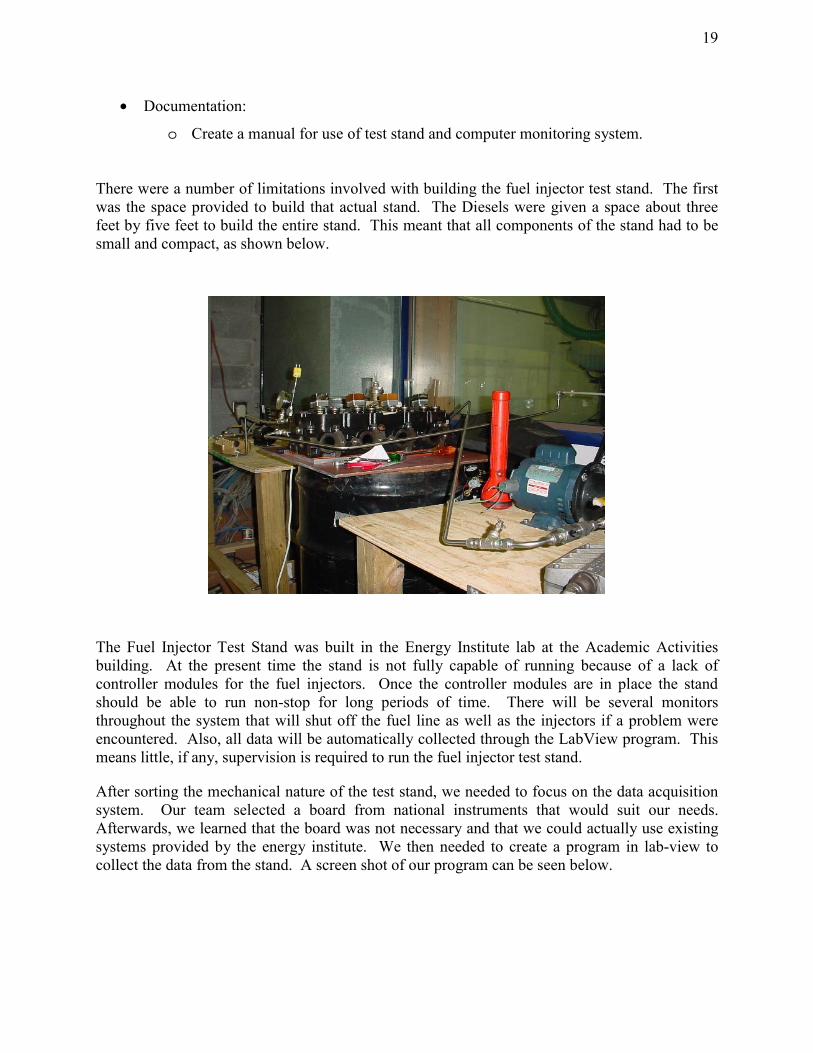
There were a number of limitations involved with building the fuel injector test stand. The first was the space provided to build that actual stand. The Diesels were given a space about three feet by five feet to build the entire stand. This meant that all components of the stand had to be small and compact, as shown below.
The Fuel Injector Test Stand was built in the Energy Institute lab at the Academic Activities building. At the present time the stand is not fully capable of running because of a lack of controller modules for the fuel injectors. Once the controller modules are in place the stand should be able to run non-stop for long periods of time. There will be several monitors throughout the system that will shut off the fuel line as well as the injectors if a problem were encountered. Also, all data will be automatically collected through the LabView program. This means little, if any, supervision is required to run the fuel injector test stand.
After sorting the mechanical nature of the test stand, we needed to focus on the data acquisition system. Our team selected a board from national instruments that would suit our needs. Afterwards, we learned that the board was not necessary and that we could actually use existing systems provided by the energy institute. We then needed to create a program in lab-view to collect the data from the stand. A screen shot of our program can be seen below.

20
Summary
Due to the fact that the system is currently incomplete and therefore inoperable, no data has been collected. All of the data acquisition components are in place and ready to run. Once the fuel injector firing control module arrives and the exhaust is assembled properly, testing can be conducted.
EE 403 Summary of Student Design Project Final Report
This project stems from a need to test diesel engine fuel injector durability in a laboratory setting. The design team’s task was to create a control system for the fuel injector test stand and to distribute power to the mechanical components.
We used a software program called Lab View to control the operation of the fuel injector test stand and collect the desired data. Power distribution circuitry was used to safely control the mechanical components of the test stand. Control circuitry combined with Lab View was used to provide local/remote control of the test stand during operation.
We ran out of time to complete the debugging phase of the test stand project. All electrical components have been acquired and hardware assembly has been completed. Successful signal generation of the FDCS and CI waveforms from the field point modules remains to be completed.
This project is a continuation of the “Fuel Injector Test Stand” project from Fall 2002. The goal of this phase of the project is to reverse engineer the fuel injector driver module, which governs

21
the operation of the injectors, and then to implement the test stand in the laboratory with the use of electronic controls. The previous group installed the main mechanical hardware components. These systems will need to be tested together with the current project so that steady state operation system data can be collected to establish how the system works. Eventually data will also be collected from the injectors. The following outlines the overall project deliverables:
• Fuel Injector Driver Control System • Integration of all components of the fuel injector test stand • Steady state operational data from the test stand • Description of how to instruct a person to operate the stand and systems • Weekly report of team and individual decisions and activities, including a running list
of open questions and issues to be addressed
The power distribution system is designed to fulfill the following goals:
• Distribute 240V single phase AC to the oil pump, gas pump and oil heater and 120V AC to the fuel cooling fans and the 12VDC 50A power supply
• Provide an automatic shutdown of the system and solenoid controlled pneumatic valves to shut off the fuel supply if one of the following conditions are met:
- A low-pressure signal is received on one of the pumps in Lab View - The panic button is pressed at either the test stand itself or from the Lab
View control panel • Maintain design simplicity
The distribution system also provides over current protection and ensures that each load has to be manually restarted after an automatic trip. In addition to a hardware control panel, the Lab View program will be used to control the system through a virtual control panel.
The distribution system was broken down into three parts: an AC section, a control section, and a control panel. The AC section is the load distribution section consisting of a breaker and a 120V AC controlled contactor to act as an on/off switch for each of the loads. Front panel switches, the Lab View control panel, and the safety shutdown system operate the contactors.
The purpose of the control panel is to allow local and remote operation of the test bench. The control panel is broken down into two types of circuits. Each circuit contains a momentary switch, a 12V DC single pole relay, and an N type MOSFET.
The control panel has inputs from the 12V DC power supply and switching signals from the Lab View program via the field point modules. The output of the control panel is a 120VAC signal, which controls the respective control relay in the control box.
The test bench has 5 loads: the oil pump, the oil heater, the fuel pump, the fuel cooler fans, and the safety circuit. Each load has a start/reset button and a stop/emergency stop button. The start/reset and stop switches are located on the covers of the control boxes. The emergency stop switch is a momentary break switch and is located around the corner from the test bench.

22
Figure 1 shows a block diagram of the fuel injector driver control system.
8
INJECTOR RETURNS
115VDC
CI
INJ 4
4 FDCS
FDCS
6INJ 2
-12VDC
CI
+12VDC
SAFETYRELAY
+12VDC
12VDC POWERSUPPLY
INJECTORDRIVEMODULE
FUEL INJECTOR SCHEMATIC
-12VDC
FIELDPOINTMODULE
INJ 8
2
INJ 6
Figure 1: Fuel Injector Driver Control System The control system contains all of the controls and a safety circuit. This system consists of a 12VDC 50 Amp power supply and a 120VAC control voltage bus. Lab View is used to control the firing of the fuel injectors as well as operate safety features built into the control system.
Figure 2 shows a diagram of the control system.

23
IDM
120Vac 30A30 Vdc POWER SUPPLY
C2 - AC SCHEMATIC ORC3 - AC SCHEMATIC
STO
P
STOPSTOP
1 - 30V DC 50A power supply5 - 120Vac 4spst relay5 - 120vac momentary make switch5 - 120Vac momentary break switch1 - 120Vac 10A breaker2 - 10 second time delay2 - vapor detector switch2 - solenoid operated air valve2 - 15 space 120Vac bus bar
LAB VIEW
35
4
67
8
911
10
1213
1412
SW6
LAB VIEW
PUMP CONTROL X2
35
4
67
8
911
10
1213
1412
SAFETY CONTROL
LAB VIEW
Lab View
SW5
KILL SW
12Vdc 50A
START
CONTROL SCHEMATIC
STOP
120Vac 30A
120Vac 10A bkr
C4 - AC SCHEMATIC ORC5 - AC SCHEMATIC
LAB VIEW
START
HEATER/COOLER X2
35
4
67
8
911
10
1213
1412
Lab View
AIRVALVES
RESET
PARTS LIST
Figure 2: Test Stand Control System The 120VAC control voltage has to go through the safety circuit first. The coil of the safety circuit is connected to the 120VAC control voltage bus. In line with the safety relay coil are the vapor detector contacts, the oil and gas low-pressure switches, and the local and Lab View panic safety switches. The coil also goes through one of the contacts of the relay to ensure that the system does not re-energize once the trip condition clears. The circuit can be re-energized by using either reset switch.
Summary
The EE 403W design team was issued the challenge of designing and creating a power distribution and control system for our sponsor, Energy Institute. The driving force behind this project was the need to test the durability of diesel engine fuel injectors using Dimethyl Ether fuel blends.
The design team was responsible for the successful completion of the fuel injector driver module control system, and the integration of the fuel injector test stand from an electrical standpoint. We used a combination of hardware design and software implementation to integrate all components of the fuel injector test stand.
Our design solution has both hardware and software features. The hardware aspects of the design solution include a safety relay circuit to ensure proper operation of the test stand as well

24
as a local control panel. The software side employs Lab View to remotely control the test stand operation and to collect the desired pressure/temperature data through the field point modules.
We were unable to finish the test stand project in the time allotted, but future work should be minimal and easy to complete. All hardware components have been assembled. Successful signal generation of the FDCS and CI waveforms from the field point modules remains to be completed.
25
CONCLUSION
The work summarized here for Tasks 1 and 2 of the project lead to the following conclusions.
1. While lubricity additives has been shown to yield adequate lubricity to DME when blended at sufficient concentration (see the work of Sivebaek et al.), these lubricity additives do not provide sufficient improvement to the viscosity of DME to alleviate the wear-related problems of DME. An effective viscosity improver is still needed.
2. The Cameron-Plint wear test apparatus is in the process of benchmarking, with as yet unresolved issues with regard to the o-ring durability and with regard to whether appreciable wear will be observed with DME in a reasonable test period. Nonetheless, the apparatus has been successfully demonstrated to operate on diesel fuel.
3. The Injector Durability Stand is nearing completion, and with some support from summer hire students, will be operational by Fall 2003.
4. Due to the delays in the implementation of the Cameron-Plint device and the change of direction 12 months ago on the Injector Durability Stand, a nine month no-cost extension of this project was requested and granted by the NETL. We expect to have significant test data and substantive conclusions by the end of the extended contract period.

26
REFERENCES [1] Bhide, S.V., Boehman, A.L. and Perez, J.M., “Viscosity of DME-Diesel Fuel Blends,” in
ACS Fuel Chemistry Division Preprints, 46(2), 400-401 (2001). [2] Sivebaek, I. M., Sorenson, S. C., and Jakobsen, J., 2001, SAE paper no. 2001-01-2013. [3] Eirich, J., E. Chapman, H. Glunt, D. Klinikowski, A.L. Boehman, J.G. Hansel and E.C.
Heydorn, “Development of a Dimethyl Ether (DME)-Fueled Shuttle Bus,” Society of Automotive Engineers Technical Paper No. 2003-01-0756. Presented at the SAE 2003 World Congress & Exhibition, Detroit, MI, March 2003.

27
ACKNOWLEDGMENT We are grateful to the National Energy Technology Laboratory for supporting this work. We would also like to thank Ron Wennmacher and Karl Sickman of Caterpillar for their support and assistance.