impact of light on augmented reality1272321/...impact of light on augmented reality – evaluating...
TRANSCRIPT

Linköpings universitetSE–581 83 Linköping
+46 13 28 10 00 , www.liu.se
Linköping University | Department of Computer ScienceBachelor thesis, 16 ECTS | Datateknik
2018 | LIU-IDA/LITH-EX-G--18/072--SE
Impact of light on augmentedreality– Evaluating how different light conditions affect the per-formance of Microsoft HoloLens 3D applications
Effekten av ljus på augmented reality– Utvärdering av hur olika ljusförhållanden påverkarfunktionaliteten hos Microsoft HoloLens 3D-applikationer
Lillemor Blom
Examiner : Zebo Peng
External supervisor : Magnus Hammerin

Upphovsrätt
Detta dokument hålls tillgängligt på Internet – eller dess framtida ersättare – under 25 årfrån publiceringsdatum under förutsättning att inga extraordinära omständigheter uppstår.Tillgång till dokumentet innebär tillstånd för var och en att läsa, ladda ner, skriva ut enstakakopior för enskilt bruk och att använda det oförändrat för ickekommersiell forskning och förundervisning. Överföring av upphovsrätten vid en senare tidpunkt kan inte upphäva dettatillstånd. All annan användning av dokumentet kräver upphovsmannens medgivande. Föratt garantera äktheten, säkerheten och tillgängligheten finns lösningar av teknisk och admin-istrativ art. Upphovsmannens ideella rätt innefattar rätt att bli nämnd som upphovsman iden omfattning som god sed kräver vid användning av dokumentet på ovan beskrivna sättsamt skydd mot att dokumentet ändras eller presenteras i sådan form eller i sådant sam-manhang som är kränkande för upphovsmannenslitterära eller konstnärliga anseende elleregenart. För ytterligare information om Linköping University Electronic Press se förlagetshemsida http://www.ep.liu.se/.
Copyright
The publishers will keep this document online on the Internet – or its possible replacement– for a period of 25 years starting from the date of publication barring exceptional circum-stances. The online availability of the document implies permanent permission for anyone toread, to download, or to print out single copies for his/hers own use and to use it unchangedfor non-commercial research and educational purpose. Subsequent transfers of copyrightcannot revoke this permission. All other uses of the document are conditional upon the con-sent of the copyright owner. The publisher has taken technical and administrative measuresto assure authenticity, security and accessibility. According to intellectual property law theauthor has the right to be mentioned when his/her work is accessed as described above andto be protected against infringement. For additional information about the Linköping Uni-versity Electronic Press and its procedures for publication and for assurance of documentintegrity, please refer to its www home page: http://www.ep.liu.se/.
c© Lillemor Blom

Abstract
Microsoft HoloLens is a headmounted augmented reality system providing users theability to experience three-dimensional virtual content. This could be used in applicationsaimed at industry where users could use augmented reality to easily access informationand receive instructions. For this to be suitable for industry, the system must be robust.One property of robustness was chosen for this thesis: system performance in conditionsof different levels of light. A prototype implementing a use case for future industry wasdeveloped, as well as two additional smaller applications to facilitate experiments. Exper-iments were performed to investigate how different light levels affects the functionality ina 3D holographic application running on HoloLens and how the visibility of virtual con-tent was affected in conditions with bright and heterogeneous backgrounds. The resultsshowed that the functionality of the holographic application was not significantly affectedexcept in very dark conditions, and that bright and messy backgrounds pose a problem tohologram visibility.

Acknowledgments
I would like to thank my examiner Zebo Peng for his patience, my external supervisor Mag-nus Hammerin for help and support, Torbjörn and Per for sharing their wisdom on AR andotherwise, my test subjects Mårten, Gustav, and Alexander P, my (now) colleagues for beingawesome in general, and last but not least my boyfriend Tomas for all his support.
iv

Contents
Abstract iii
Acknowledgments iv
Contents v
List of Figures vii
List of Tables viii
Terminology and definitions ix
1 Introduction 11.1 Background . . . . . . . . . . . . . . . . . . . . . . . . . . . . . . . . . . . . . . . 11.2 Motivation . . . . . . . . . . . . . . . . . . . . . . . . . . . . . . . . . . . . . . . . 21.3 Aim and research questions . . . . . . . . . . . . . . . . . . . . . . . . . . . . . . 21.4 Delimitations . . . . . . . . . . . . . . . . . . . . . . . . . . . . . . . . . . . . . . 2
2 Theory 32.1 Augmented reality . . . . . . . . . . . . . . . . . . . . . . . . . . . . . . . . . . . 32.2 Microsoft HoloLens . . . . . . . . . . . . . . . . . . . . . . . . . . . . . . . . . . . 62.3 Issues of augmented reality and different light conditions . . . . . . . . . . . . . 102.4 Measuring light conditions . . . . . . . . . . . . . . . . . . . . . . . . . . . . . . 11
3 Implementation of software 133.1 Prototype specification . . . . . . . . . . . . . . . . . . . . . . . . . . . . . . . . . 133.2 Development platform and frameworks . . . . . . . . . . . . . . . . . . . . . . . 133.3 Design choices . . . . . . . . . . . . . . . . . . . . . . . . . . . . . . . . . . . . . . 143.4 Implementation . . . . . . . . . . . . . . . . . . . . . . . . . . . . . . . . . . . . . 153.5 Additional applications . . . . . . . . . . . . . . . . . . . . . . . . . . . . . . . . 17
4 Experimental work 194.1 Properties to investigate . . . . . . . . . . . . . . . . . . . . . . . . . . . . . . . . 194.2 Experiments . . . . . . . . . . . . . . . . . . . . . . . . . . . . . . . . . . . . . . . 19
5 Results 235.1 Illuminance measurements . . . . . . . . . . . . . . . . . . . . . . . . . . . . . . 235.2 Spatial mapping . . . . . . . . . . . . . . . . . . . . . . . . . . . . . . . . . . . . . 235.3 Behavior of holograms and hand gestures . . . . . . . . . . . . . . . . . . . . . . 325.4 Visibility of virtual content . . . . . . . . . . . . . . . . . . . . . . . . . . . . . . . 32
6 Analysis and discussion 356.1 Experimental method . . . . . . . . . . . . . . . . . . . . . . . . . . . . . . . . . . 356.2 Results . . . . . . . . . . . . . . . . . . . . . . . . . . . . . . . . . . . . . . . . . . 36
v

6.3 Suitability for the given scenario . . . . . . . . . . . . . . . . . . . . . . . . . . . 38
7 Conclusion 39
Bibliography 40
List of Figures
2.1 Microsoft HoloLens . . . . . . . . . . . . . . . . . . . . . . . . . . . . . . . . . . . . . 62.2 HoloLens hardware details . . . . . . . . . . . . . . . . . . . . . . . . . . . . . . . . 72.3 Spatial map created by HoloLens . . . . . . . . . . . . . . . . . . . . . . . . . . . . . 8
3.1 Screenshots from the implemented prototype . . . . . . . . . . . . . . . . . . . . . . 143.2 Components of the prototype software . . . . . . . . . . . . . . . . . . . . . . . . . . 153.3 Screenshot of the application written for the visibility experiments. . . . . . . . . . 17
4.1 Views of the different setups for the visibility experiment . . . . . . . . . . . . . . . 21
5.1 Results of the spatial map experiments . . . . . . . . . . . . . . . . . . . . . . . . . . 25
vii

List of Tables
2.1 HoloLens hardware specifications . . . . . . . . . . . . . . . . . . . . . . . . . . . . 7
3.1 Colors used in the visibility application . . . . . . . . . . . . . . . . . . . . . . . . . 17
5.1 The results from the spatial map experiments . . . . . . . . . . . . . . . . . . . . . . 245.2 Results of the experiments investigating prototype functionality in different light
levels . . . . . . . . . . . . . . . . . . . . . . . . . . . . . . . . . . . . . . . . . . . . . 325.3 Results of visibility experiments . . . . . . . . . . . . . . . . . . . . . . . . . . . . . . 33
viii

Terminology and definitions
Augmented reality (AR) - a view of reality that is augmented with virtual objects, viewedusing a device such as a tablet or a head mounted display.
Field of view (FOV) - in the context of augmented reality it is the area of the world that canbe seen through the AR system, i.e. the part that can be augmented with virtual content.
Head mounted display - a device worn on the head, with displays positioned in front of theuser’s eyes. In combination with a computer it can be used to view reality, virtual reality oraugmented reality.
Hologram - holographic or virtual content, something that is seen through the augmentedreality system that is not a physical entity.
ix


1 Introduction
Augmented reality is the concept of creating an experience where virtual elements are inte-grated in the real world. The virtual content augments the reality around the user. While theconcept of augmented reality - AR for short - is not new, its popularity in both the generalpublic and the scientific community may never have been higher [1]. A recent example ofan augmented reality system which managed to gain the attention of the general public isthe mobile phone application Pokemon Go [2]. There is extensive research made on how theuse of augmented reality may be applied to many varying areas besides games, such as ed-ucation [3] and health care [4]. There are different ways of implementing augmented reality,from apps running on smartphones to advanced systems developed specifically for the useof AR.
In this thesis a prototype application has been developed for wearable augmented realitydevice Microsoft HoloLens that implements a possible scenario of interaction between humanand machine in an industrial context. That application and two smaller applications havethen been used to examine how the performance of the HoloLens system is affected whenused in different light conditions.
1.1 Background
Industry 4.0 is a term for a vision of how manufacturing industry can implement new tech-nologies to reach new levels of efficiency and flexibility [5]. Systems and devices will beconnected to each other and to the Internet in order to communicate and share data betweenthemselves and with humans. Systems will be smart and automated and require as little hu-man interaction as possible, and by being able to present large quantities of data to humansin an easily accessible manner, human decisions will be well-grounded and easy. One pos-sibility of how this interaction between human and machine could be facilitated in such ascenario is to use augmented reality. A hypothetical scenario is a factory where a technicianuses an AR system to be able to get information about a machine presented in his or her fieldof view just by looking at the machine, instead of having to interact with the machine via aconventional computer and screen.
1

1.2. Motivation
1.2 Motivation
In 2016, Microsoft launched the first edition of the HoloLens wearable computer system [6].It is a system that permits the creation of applications featuring advanced augmented reality,using well-known software development platforms and providing extensive documentationfor developers. Due to the promising features of this system, it could be a suitable candidatefor implementing software that meets the criteria of the scenario described above.
One question that can determine how useful augmented reality systems are in real-worlduse cases is how they function outside optimal conditions. Because of this, it is of inter-est how robust applications running on the HoloLens system are with regards to differentenvironmental properties. A property which is likely to vary is lighting conditions in the sur-rounding environment. Lighting condition is a factor that is known to affect various aspectsof performance and experience of augmented reality systems. Microsoft states in its docu-mentation of HoloLens that some aspects of the performance of HoloLens can be affectedby dark light conditions, but does not state exactly at what levels of light the problems mayoccur [7]. The displays used in HoloLens are based on a technology that may make it hard tosee visual content in an environment with bright light [8].
1.3 Aim and research questions
The aim of the thesis is to answer the following questions:
1. How is the performance of a holographic application running on HoloLens affected byvarious light conditions?
2. Can different light conditions have a detrimental effect on user experience of HoloLensholographic applications?
A small prototype implementing some basic criteria of the scenario for future use was tobe implemented. A set of properties that may be affected by various levels of ambient lightwas to be determined by the experiences gained when developing the prototype. Evaluationof these properties and the effects of various light conditions on user experience was to beevaluated using the implemented prototype.
1.4 Delimitations
The thesis does not compare the implemented solution to other augmented reality systemsor to any non augmented reality solutions. The experiments are made under different levelsof static light with as little dynamic change in light as possible. Dynamic changes in light arenot part of the evaluation of the experiments.
2

2 Theory
This chapter presents general theory on the technical field of augmented reality, a descriptionof the Microsoft HoloLens system and a short overview of some of the known effects of lighton the performance of augmented reality systems.
2.1 Augmented reality
Augmented reality is the concept of creating an experience where virtual elements are addedto the real world around the user. A commonly accepted definition of the term augmentedreality is that an augmented reality system must implement the following three conditions[8], [9]:
1. It combines real and virtual elements
2. It is interactive in real time
3. It is registered in three dimensions
To fulfill the first condition the system typically has a display that can show both realand virtual elements. The second condition is fulfilled by the system having a computer thathandles input and output in real time. The last condition is fulfilled by the system havingtracking ability. The tracking ability is used to track the view and position of the AR systemin the real world. This must be known for the system to be able to determine where and howto present virtual elements over the user’s view of the real world [8]. Different technologiesfor displays and tracking are presented in later sections of this chapter.
A concept that is related to augmented reality is virtual reality. The difference betweenthe two concepts is that in virtual reality the virtual environment completely replaces the realenvironment, whereas augmented reality presents a combination of real and virtual elements[8].
There are several fields where research is made exploring if and how augmented realitycan be applied. Examples are for AR to be used in education [3], in experiencing art andculture [10], in the medical field [11], and in training and maintenance in industry [12].
As implied by the broad definition of an augmented reality system stated above, the im-plementation of AR systems can vary greatly. There are frameworks that permit the devel-opment of augmented reality applications that can be run on smartphones. There are several
3

2.1. Augmented reality
examples of head mounted devices specifically developed for AR and virtual reality. Aug-mented reality that can be experienced by a crowd simultaneously can be implemented byusing external projectors that display virtual content by projecting it on real life objects.
2.1.1 Display types
A display used in an AR system must be able to show a combination of virtual and realelements. The technologies for achieving this can be divided into four categories: video-based, optical see-through, eye-multiplexed and projection on a physical surface [8].
For video-based displays and optical see-through the virtual content is superimposed onthe view of the real environment, presenting a complete view where the virtual content isseemingly positioned in the real world. Video-based displays work as the display on a cellphone or on a TV. The real environment is filmed with one or several cameras, virtual contentis added to the image of the real world and the combined image is presented as pixels on thedisplay. Optical see-through differs from video-based displays in that only the virtual contenthas to be shown on the display. The real environment is seen through the transparent displayjust like looking at the world through a window or a pair of ordinary glasses.
Eye-multiplexed displays do not superimpose the virtual content on the view of the realworld. The virtual content is presented such that the user must mentally add it the realenvironment. That virtual content can be presented in a smaller display that only covers partof a user’s field of view.
Projection on a physical surface is where film projectors are used to project virtual contenton real objects. An example of this can be to use several projectors to project different designsonto a physical model of a car.
2.1.2 Display configurations
There are several variations on where the display is positioned between the user’s eyes andthe world [8]. For a head-attached or head-mounted display (HMD) the display is positionednear the user’s eyes similar to goggles or a pair of glasses. Hand-held or body-attacheddisplays are held by the user, for example in the form of a smart phone or tablet.
A spatial display is more or less fixed in position, for example in the form of a semi-transparent mirror in front of the background in which the virtual content will be positioned.This configuration can be used to give many users access to the augmented reality view si-multaneously.
As mentioned above, another form of spatial display configuration is where the virtualcontent is projected onto a real object, which means that the display is the real object itself.
2.1.3 Tracking technologies
To provide an experience where the user perceives that virtual objects exist in and interactwith the real environment when seen through the AR system, the AR system must continu-ously determine where on the display the virtual content should be positioned.
The task of the tracking system is to determine the position and orientation, also knownas the pose, of the AR system’s view in relation to specific markers or natural properties [8],[13]. By tracking changes in the pose, the system can recalculate how to correctly display thevirtual element as the user view moves. The tracking system must register how the user’sview moves in three dimensions, left/right, closer to/farther away, and up/down. It mustalso register rotation in these three dimensions, i.e. the pitch, yaw and roll.
An example is a hologram of an apple that is intended to be shown in the AR view asif it is placed on a real table. As the user is moving towards the table with the apple, usinga device with an AR display, the image of the virtual apple must be rendered increasingly
4

2.1. Augmented reality
larger in the AR view. If the users walks around the table watching the apple hologram, theimage of the apple must rotate with the user’s changing view.
Vision-based tracking
Systems using vision based tracking use optical sensors for capturing data needed to de-termine the user’s pose. Optical sensors can be divided into three categories, sensors thatregister infrared light, sensors that registers visible light, and 3D structure sensors [8].
Infrared sensors detect light in the infrared spectrum. The targets for the infrared sensorscan be either passive or active. An active target emits its own infrared radiation. The passivetarget reflects back infrared radiation that is emitted by a source of infrared light, typicallypositioned near the camera.
Visible light sensors detect, as the name suggests, visible light. Two techniques usingvisible light sensors are fiducial tracking and natural feature tracking. Fiducial tracking isbased on detecting fiducials, also known as markers, defined by Billinghurst et al. [8] asartificial landmarks that are added to the landscape to aid in registration and tracking. Thefiducials can consist of a specific pattern printed on paper or formed by LEDs of differentcolors. Fiducial tracking is relatively simple and dependable since fiducials can be createdto have a limited set of possible designs and to be easily discerned from naturally occurringfeatures, which makes the image processing relatively simple. The downside is that it is notpractical in all situations to add these markers to the environment. Natural feature trackingavoids the issue of having to add markers to the environment by using image processingto detect features of the existing environments to determine the position and orientation ofthe user’s view. The downside is that the image processing is more complicated than fordetection of fiducial markers.
3D-structure sensors can register information about three-dimensional objects by detect-ing depth information about the surrounding environment. Two techniques for detectingdepth are structured light [14] and time-of-flight [15]. Structured light is used for examplein the KinectFusion system [16]. The technique uses two cameras and at least one projectorthat projects a structured light pattern onto a physical scene. The two cameras then uses thestructured light to find the pixel pairs between the two images, and that is used to calculatethe depth map of that scene. Systems that uses time-of-flight sensors send out a light signaland detects how the returning signal has changed for a given set of points, which is then usedto calculate the depth information of the scene.
Inertial tracking
Inertial tracking is done through a combination of sensors such as accelerometers and gyro-scopes, commonly known as an Inertial Measurement Unit (IMU) [8], [13]. These sensors cantogether determine the objects specific force and angular rate. Advantages of inertial track-ing include not having range limitations, not being affected by competing optical, magnetic orother sources, as well as being able to operate where there is no line-of-sight. Disadvantagesinclude accumulation of errors in position and orientation over time .
GPS-tracking
This tracking technology uses the GPS satellite network to determine the position of the ARsystem. Since the technology uses satellites, the positioning is most reliable outdoors [8].
Magnetic tracking
Magnetic tracking uses some source that emits a magnetic field and a sensor that can detectvarious properties of the detected magnetic field to determine the sensors position in relationto the transmitter. The tracking accuracy is affected by nearby objects emitting magnetic
5

2.2. Microsoft HoloLens
fields, such as electronic devices, and there is a strong limitation on the distance possiblebetween the sensor and emitter [8].
Hybrid tracking
As the name suggests, systems that uses hybrid tracking combine sensors from differenttracking techniques. This is typically a combination of vision-based tracking and for exampleinertial tracking or GPS tracking. It is a way of gaining the advantages of different trackingtechniques while reducing the disadvantages, such as being able to correct the errors for theinertial tracker accumulated over time by using information from the vision based tracker [8].
2.2 Microsoft HoloLens
Figure 2.1: Microsoft HoloLens[17]
Microsoft HoloLens is in Microsoft’s own words an untethered holographic computer[18]. HoloLens is a head-mounted augmented reality system, as shown in fig 2.1, that doesnot need an external computer, instead the computational power used is built into the device.It runs a version of Windows 10 as operating system. Applications developed for the Univer-sal Windows Platform (UWP) can be run on the system, but cannot use holographic content.Microsoft provides an API for developing holographic applications in the game engine Unity[19].
2.2.1 Hardware
HoloLens has optical see-through lenses (see fig 2.2a). It has a number of sensors to obtaintracking information and information about the surrounding environment (see table 2.1 andfig 2.2b). What Microsoft calls environment understanding cameras are visible light cameraslocated to the right and left of the center camera, which are used to determine the fixed posi-tion of the user in space [20]. The depth camera emits infra-red light and uses time-of-flightsensors to gather depth information for the environment [21].
The device has built-in speakers and an audio jack for headphones. The only buttonson the device are the power button, and three buttons used to, among other things, adjustbrightness and volume and take screenshots. It can communicate through Wifi, Bluetooth orMicroUSB cable.
It is possible to use Bluetooth keyboards, gamepads and some other devices that usesBluetooth. There is also a specially developed hand-held device called a clicker that can beused for scrolling and clicking in HoloLens applications [22].
6

2.2. Microsoft HoloLens
Property DefinitionOptics See-through holographic lenses
Sensors
1 IMU4 environment understanding cameras1 depth camera1 2MP photo/HD video camera4 microphones1 ambient light sensor
Processors Intel 32 bit processorCustom-built Microsoft Holographic processor
Memory 64GB Flash2GB RAM
Weight 579 g
Battery life 2-3 hours of active useUp to 2 weeks standby
ConnectivityWifi 802.11acBluetooth 4.1 LEMicroUSB 2.0
Table 2.1: Hardware specifications of Microsoft HoloLens[18].
(a) Displays (b) Sensors
Figure 2.2: HoloLens hardware details. a) The see-through displays [23]. b) The positions ofthe sensors [24]. The depth camera is located at the center, above the main camera. The twoenvironment understanding cameras are placed one each at the left and right of the centercamera.
2.2.2 Optics
HoloLens uses a variant of optical see-through display technology called waveguides withsurface relief gratings (see fig 2.2a) [21]. This is different from some see-through optics tech-nologies where an image of the virtual content is projected onto a semi-transparent mirrorand reflected into the user’s eyes while the background is also visible. Instead, the imageis transferred into the waveguides and transmitted through them by total internal reflection,where the grates bend the transmitted light so that it exits the waveguides towards the userseyes at the intended position [25]–[27].
The maximum supported resolution for HoloLens applications is 720p (1268x720 pixels)[28]. The technical documentation suggests that applications show graphics at 60 frames persecond for an optimal user experience [29]. Microsoft provides values for two optical prop-erties they have named the holographic resolution and holographic density, which are 2.3million total light points and 2.5 thousand light points per radian, respectively. An expla-nation of the relations between common resolution, holographic resolution, and holographicdensity could not be found in the official documentation. Other sources explained that com-mon resolution and holographic resolution and density are different measurements that bothrelate to the quality of the holograms [30]. Higher holographic density is said to lead to
7

2.2. Microsoft HoloLens
brighter and sharper holograms [31]. The exact reason why conventional resolution is not agood measurement could not be found by the thesis author.
2.2.3 Spatial mapping
Microsoft HoloLens has the capability to create a 3D-model of the surrounding space, a pro-cess Microsoft calls spatial mapping [32]. A visualization of the spatial map with the polygonshighlighted can be seen in fig 2.3. The spatial map is used to guide where to place virtual el-ements so that they seem to interact with the real environment, e.g. a virtual apple placed ona table or a virtual ball bouncing against a wall. This also permits the virtual content to be oc-cluded by real objects, e.g. virtual content can be hidden behind real objects. The spatial mapcan be saved for later use on the same HoloLens device or shared with others. When usingthe spatial mapping functionality in a 3D HoloLens app, the map is updated continuously asmore sensor data is received to create a more detailed and updated model of the surroundingenvironment.
Figure 2.3: Screenshots of visualization of the spatial map created by HoloLens. The applica-tion used for the spatial map experiments described in section 3.5.2 were used when takingthese pictures. Different distances are indicated by different colors in the mesh.
2.2.4 Spatial persistence
Virtual objects in a HoloLens app are able to retain their position in space between applicationsessions [32]. A hologram that is positioned on a chair will have that position the next time theapplication is launched. The Holographic API provides the ability to create a spatial anchor,a point in space that virtual content can be positioned in relation to. Spatial anchors can besaved to the HoloLens secondary memory and retrieved the next time the app is started. Thecaveat is that the system must be able to recognize the surroundings, which mean that thereare limits to how much the environment can change for this to work. No documentation onthe exact method used by the HoloLens to determine the position of a spatial anchor from theavailable sensor data could be found.
8

2.2. Microsoft HoloLens
2.2.5 Methods for input and output
The modes used for input and output on Microsoft HoloLens differ in some aspects whencompared to a laptop, a mobile phone or a tablet.
Gaze tracking
A form of input that is used to target objects in HoloLens is gaze tracking [33] (not to beconfused with the augmented reality term tracking explained earlier in this chapter). Thiscorresponds to using a computer mouse to be able to target different objects in a computersystem with a graphical user interface. The gaze determines where the user is looking at theworld by registering the position and orientation of the user’s head. It is the position of thehead and not the direction of the eyes that determines where the gaze is aimed, which meansthat to move the gaze the user has to move his or her head.
Gesture input
HoloLens has built in support to recognize a number of hand gestures that can be used foruser input [34]. HoloLens can determine the position and some characteristics of the right andthe left hand of the user while it is positioned in an area in front of the HoloLens. These basicgestures that HoloLens can recognize permit the user to, among other things, click, hold andscroll in a 2D application, and move or activate some part of a hologram. Combined with thegaze tracking, gestures can be used to interact with holograms and 2D-applications in waysthat in some aspects are consistent with how a user would interact with conventional device,such as a tablet or mobile with touchscreen. Developers can also use the ability to detect theposition and characteristics of the hand and the basic gestures to combine into custom modesof interaction with an app.
Voice input
Another form of user input is by using voice commands [35]. Detection of some standardphrases are implemented in the system, such as "select", which can be used instead of air-tapping or using the clicker. It is also possible to make selections by speaking the text dis-played on buttons and menus. Many of the features of the Windows 10 digital assistantCortana are also available for HoloLens [36].
There is extensive support for using custom voice commands when developing applica-tions for HoloLens. Creating custom voice commands can be implemented as simply as byproviding a string of the new command to an element of the HoloLens API that recognizeskeywords [37]. Only English pronunciation of voice commands is supported so far.
Spatial sound
In addition to visual output, Hololens features the ability to play spatial sound from holo-graphic content. Spatial sound is the mechanism of playing sound in a way that simulatesthe sound coming from different locations in space [38].
2.2.6 Operating system and holographic shell
Microsoft HoloLens runs Windows 10 as operating system, with almost all functionalityavailable as on laptops and desktops running Windows 10. The holographic shell is the namefor what can be seen as the HoloLens alternative to the desktop when running Windows 10on a conventional computer, i.e. the starting point from which applications can be started andwhere application windows can be placed. Apps based on the Universal Windows Platform(UWP) [39] that are executed on HoloLens are placed as 2D windows along physical walls orobjects in the holographic shell. When starting a third party 3D application, the surrounding
9
2.3. Issues of augmented reality and different light conditions
virtual space is taken over by the content of that application and the content placed in theholographic shell is not visible.
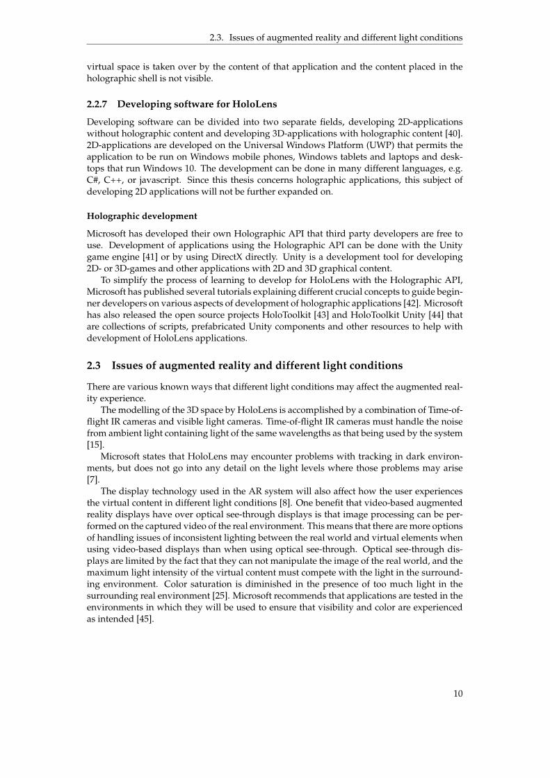
2.2.7 Developing software for HoloLens
Developing software can be divided into two separate fields, developing 2D-applicationswithout holographic content and developing 3D-applications with holographic content [40].2D-applications are developed on the Universal Windows Platform (UWP) that permits theapplication to be run on Windows mobile phones, Windows tablets and laptops and desk-tops that run Windows 10. The development can be done in many different languages, e.g.C#, C++, or javascript. Since this thesis concerns holographic applications, this subject ofdeveloping 2D applications will not be further expanded on.
Holographic development
Microsoft has developed their own Holographic API that third party developers are free touse. Development of applications using the Holographic API can be done with the Unitygame engine [41] or by using DirectX directly. Unity is a development tool for developing2D- or 3D-games and other applications with 2D and 3D graphical content.
To simplify the process of learning to develop for HoloLens with the Holographic API,Microsoft has published several tutorials explaining different crucial concepts to guide begin-ner developers on various aspects of development of holographic applications [42]. Microsofthas also released the open source projects HoloToolkit [43] and HoloToolkit Unity [44] thatare collections of scripts, prefabricated Unity components and other resources to help withdevelopment of HoloLens applications.
2.3 Issues of augmented reality and different light conditions
There are various known ways that different light conditions may affect the augmented real-ity experience.
The modelling of the 3D space by HoloLens is accomplished by a combination of Time-of-flight IR cameras and visible light cameras. Time-of-flight IR cameras must handle the noisefrom ambient light containing light of the same wavelengths as that being used by the system[15].
Microsoft states that HoloLens may encounter problems with tracking in dark environ-ments, but does not go into any detail on the light levels where those problems may arise[7].
The display technology used in the AR system will also affect how the user experiencesthe virtual content in different light conditions [8]. One benefit that video-based augmentedreality displays have over optical see-through displays is that image processing can be per-formed on the captured video of the real environment. This means that there are more optionsof handling issues of inconsistent lighting between the real world and virtual elements whenusing video-based displays than when using optical see-through. Optical see-through dis-plays are limited by the fact that they can not manipulate the image of the real world, and themaximum light intensity of the virtual content must compete with the light in the surround-ing environment. Color saturation is diminished in the presence of too much light in thesurrounding real environment [25]. Microsoft recommends that applications are tested in theenvironments in which they will be used to ensure that visibility and color are experiencedas intended [45].
10

2.4. Measuring light conditions
2.4 Measuring light conditions
When looking at use of an AR system outside of an office environment in various industrialenvironments, light conditions can be expected to vary considerably. Ideally, an AR-systemfor industrial use should work as intended in light conditions ranging from dim lighting ordarkness, to bright sunshine.
The metric that was used to quantify light conditions is illuminance. Illuminance is ameasurement of how much light is falling onto a surface. The light can come from eitherartificial or natural sources, such as overhead light fixtures and daylight through a window.The SI derived units - e.g. derived from units of measurement defined by the InternationalSystem of Units [46] - to measure illuminance is lux or lumens per square metre [47].
11


3 Implementation of software
This chapter will present the software created for this thesis. A larger prototype applicationwas developed as a simple implementation of the proposed scenario, to help determine howthe experiments would be designed and to then be used in some of those experiments. Twosmall additional applications were also developed, since separating functionality into severalapplications instead of integrating it all into the larger prototype would simplify the designof the experiments.
3.1 Prototype specification
The aim of the prototype was to implement a simple demo that showcases some fundamentalconcepts of developing holographic applications for HoloLens and as far as possible imple-ment the proposed scenario. The nature of what the prototype should implement was de-cided through discussion of the scenario described in the introduction with the external su-pervisor. Through those discussions, a small set of characteristics that the prototype shouldfulfill was determined:
• The application is a 3D augmented reality application
• It must be possible to display information particular to an object or location in the realenvironment
• The information must be reachable through augmented reality interaction, such as look-ing at an object
• The point in space that relates to a specific set of information must be persistent, i.e. theapplication must remember between executions the location in space that is connectedto reaching information about a specific object
3.2 Development platform and frameworks
The prototype was developed using the game engine Unity version 5.5.2p1 Personal and Vi-sual Studio Community 2015 Version 14.0.25431.01, with scripts written in C#. The choice wasmainly made due to this setup being recommended by Microsoft. Unity has a user friendly
13

3.3. Design choices
graphical user interface and extensive support through official and unofficial channels, whichmakes it easier as a beginner to get started with developing holographic applications than anyother alternatives.
Microsoft provided HoloToolKit and HoloToolKit-Unity [44] (later renamed MixedReal-ityToolkit [43] and MixedRealityToolkit-Unity), two open source projects that contain re-sources that can be used by HoloLens developers. HoloToolKit-Unity was of main interestsince the prototype was developed using Unity. The resources it contains are scripts, shaders,materials and prefabricated Unity components as well as complete examples of various func-tionalities. The resources were used for the development of the prototype in various ways, insome cases the resources could be used as they were, in other cases used in modified form orused to learn how the system works. Several tutorials provided by Microsoft were also usedas learning tools, and some components from the code examples were used in modified orunmodified form [42].
(a) Overview (b) Dragging icon
(c) Information flags (d) Icons occluded
Figure 3.1: Screenshots from the implemented prototype.
3.3 Design choices
There were several choices to be made: how would the user interact with the application toretrieve the desired information, and how should the information be presented to the user?
How the user would choose what information they are interested in can roughly be di-vided into two modes: either there is a virtual object that exists to provide a target for in-teraction, or the information is retrieved by looking at the real object of interest without anobvious virtual object for interaction.
The former alternative was chosen, since it was simpler and would provide the virtualcontent suitable for use in the light condition experiments. It was decided that a simplethree-dimensional sphere would function as that interaction object (see fig 3.1). From hereon, such spheres are named icons.
The other choice was how to present the information. Either the information could be pre-sented next to the real object or the icon, or it could be presented as headlocked informationthat follows the users view. The first alternative was chosen since Microsoft design guidelinesrecommends not using headlocked content for HoloLens applications, as well as being moresuitable for use in the upcoming experiments.
14

3.4. Implementation
The application was designed to have two modes of operation, an editing mode whereicons can be created and placed at the desired position in space, and a mode where the userretrieves information from the icons by looking at them.
An interaction is made up of two parts, how to focus on the object to interact with, andthen choosing how to interact with it. Gaze, i.e. a marker directed by the user’s head move-ment, was chosen to direct focus. It is the choice recommended by Microsoft. To move anicon to its desired position in space, the choice was made to use the gaze to focus on the icon,and then move it by making a holding gesture (see fig 3.1b). An alternative method for mov-ing an icon was also available, where after having selected the icon to be moved by using anair tap hand gesture the icon’s position would be directed by where the user’s gaze hits thespatial map. After a brief test that alternative was discarded, since icons would not neces-sarily be positioned near a real object and since it made it hard to make small and accurateadjustments in position.
3.4 Implementation
A Unity project generally consists of a set of basic components, a light source, a camera,managers that handle events, and 2D or 3D graphical elements that will be rendered in theapplication view. All components can have scripts and various other elements connectedto them that decide their behavior, such as scripts handling what happens when an objectcomes into focus or is selected. Fig 3.2 shows the hierarchy of project components for theprototype and an example of the various scripts and other elements that can be connectedto a component, in this case to the component SphereIcon. As the figure shows, this projectconsists of many components with connected elements, too many to cover in this report. Onlythe main components that are specific to development of HoloLens applications and to thisprototype will be covered. Documentation on development of general Unity applications isavailable on the official Unity website [41].
(a) Project hierarchy.
(b) Elements connected to component SphereIcon.
Figure 3.2: Hierarchy of project components (a) and example of scripts and other elementsconnected to a component (b).
15

3.4. Implementation
3.4.1 Interaction
The GazeManager script avaliable in the HoloToolKit [44] manages all that is related to thegaze, such as determining where it hits and which virtual object the gaze is aimed at. It isa standard component in many HoloLens applications and could be used without modifica-tion.
The ability to drag an object by performing a holding gesture is handled by a script basedon the HandDraggable script available in the HoloToolkit. Some alterations and additionswere made to handle how the object behaves when dragged. Handling of spatial anchorsand interaction of the dragged objects with the mesh created by spatial mapping of the sur-rounding environment were also implemented.
The ability to use voice commands can be implemented by using standard componentsfrom the HoloToolkit, and was added to the prototype to facilitate application interactionduring experiments.
3.4.2 Spatial persistence
When the icons are positioned in space they must retain that position even between applica-tion sessions and when the HoloLens has been powered off and turned on again, regardlessof the time that has passed between these events. For HoloLens, this is achieved by attachingworld anchors to some or all virtual objects, defining the objects’ spatial coordinates in rela-tion to those world anchors and storing them in the world anchor store. This was done byimplementing a world anchor store that stores the world anchors locally on the device withsimple strings as identifiers. World anchors can then be retrieved and used to give virtualobjects the position in space which they had when the application was closed.
The WorldAnchorManager script available in the HoloToolkit was used largely withoutmodification. Examples of usage of the world anchors was found in various examples in theHolographic Academy code tutorials and on developer forums online.
3.4.3 Spatial mapping
Mapping of the physical objects in the surround environment was needed since the iconsshould not be possible to place inside of physical objects. This functionality was avaliable inthe HoloToolkit as scripts. Rudimentary collision handling was implemented using raycast-ing against the retrieved spatial map. Raycasting is the act of shooting, or casting, an invisibleray from a point of origin in a determined direction to detect if that ray intersects with an-other virtual object. In this case this was used to determine if collision with the spatial maphad occurred in the direction of movement when dragging an object. The use of raycastingin collision detection is a tried technique in Unity development, and examples of use werefound in both Unity documentation and in the Holographic Academy tutorials [48].
Occlusion is the concept of rendering virtual objects so that they are seemingly hiddenbehind physical objects, as can be seen in fig 3.1d. This is optional, but was chosen to furtherencourage the illusion that the virtual icons were real objects. This was implemented usingcomponents from the HoloToolkit, with guidance from various examples in the Academytutorials.
3.4.4 Information presentation
The information was decided to be presented as text in panes that pop up adjacent to the icons(see figs 3.1c, 3.1d). This was decided mainly because of its relative simplicity to implementand its suitability for the upcoming light condition experiments. This functionality could becreated after having consulted the Unity documentation.
16

3.5. Additional applications
3.5 Additional applications
Two small applications were created to facilitate performing experiments, instead of extend-ing the prototype further.
3.5.1 Spatial map viewer
This small holographic application was created in Unity with the only purpose of showingthe spatial map created by HoloLens.
The application was based on the example from a tutorial on holographic programmingissued by Microsoft [49]. The only components used in the Unity project were a main camera,a directional light and a spatial mapping asset. The spatial mapping asset creates a spatialmap, and visualizes it by highlighting the spatial map mesh with colors that depend on thedistance from the camera to the created mesh (see fig 2.3).
3.5.2 Visibility check
The application written for the visibility experiment was written in C# as a Universal Win-dows Platform app. It consists of an application window with a word written in differentcolor combinations, as can be seen in fig 3.3. The word is randomly selected from a list of 27words of approximately the same length. By pressing a button a new word is displayed, untilfive words have been displayed and the test is over.
The colors were chosen to give many possible combinations of colors that were eithercommon in software color schemes, such as white and dark backgrounds with white or darktext, and high visibility colors such as red and blue. The light gray was used since it is recom-mended by Microsoft to be used instead of white, as white can be seen as too bright or intense[45]. The white was chosen to test the maximum brightness. The dark slate gray was chosenas a dark background, since solid black will be transparent in HoloLens applications [45].The more unusual color combinations, such as red background and blue text, was chosen toalso test if color that conventionally wouldn’t be used in software used on non see-throughdisplays would be useful for HoloLens see-through display.
Color name ARGB valueWhite #FFFFFFFFLight gray #FFEBEBEBDark slate gray #FF2F4F4FRed #FFFF0000Blue #FF0000FF
Table 3.1: Colors used in visibility application, with their corresponding ARGB hexadecimalvalues.
Figure 3.3: Screenshot of application written for the visibility experiments.
17


4 Experimental work
This chapter presents the different experiments made, using the prototype application andthe two additional applications that were developed for this thesis.
4.1 Properties to investigate
The following aspects of the functionality of the Microsoft HoloLens system that could beaffected by different light conditions were determined during the development of the proto-type:
• the ability to create a spatial map that is as accurate as that created in favorable condi-tions
• the system recognizing gestures
• holograms maintaining spatial persistence
• holograms staying stationary
• the visibility of virtual content
4.2 Experiments
It was decided that the experiments would be designed to investigate the differences in ap-plication behavior in environments with different static levels of light, after the system hadstabilized to the current light level. Such experiments would be relatively easy to design andevaluate, and that would be a natural starting point to investigation in this topic. A follow-upon that could have been to investigate how the system behave during dynamic variations ofthe light level, for example how the system would behave when going from indoor lightingto daylight outside, if time would have permitted.
4.2.1 Spatial mapping
No suitable methods for evaluating the quality of the spatial map using quantitative mea-surements could be found. Therefore, an experiment was designed where the spatial map
19

4.2. Experiments
of a set of physical objects created under different static levels of ambient light would beobserved and qualitatively compared to the spatial map created of the same set of objectsduring reference lighting conditions. The spatial mapping application which only reveals thecreated spatial mesh was used for this experiment.
How well the spatial map correlated to the physical objects was observed first in light con-ditions that corresponds to normal office lighting conditions, with light coming both from ar-tificial light sources as well as daylight through windows. This reference was chosen to be thenormal light conditions during daytime in the offices where the author was working, whichwas within the recommended limits for lighting of an office as stated by Arbetsmiljöverket[50]. "Normal" in this context would perhaps better be seen as "not extreme", as what is nor-mal office lighting is somewhat subjective and could vary with season and time of day. Thelight levels were then regulated in steps to lower and higher levels. The experiment was alsoperformed outdoors in natural daylight.
Two cardboard boxes with the dimensions 30 x 30 x 10 cm and 32 x 10 x 10 cm were placedon the floor against a wall in a room with no windows or on the ground on a patio outside.The height of the HoloLens was 110 cm above the floor and 150 cm from the wall where theboxes where placed. The application was started, the user (the author) took one step to theright, one step to the left while still looking at the boxes, and then waited 10 s before thequality of the spatial map was noted. One of the boxes was then moved approximately 10 cmtowards the other box before repeating the above procedure before again noting the shape ofthe resulting spatial map. The position of the boxes for both configurations was marked ona large piece of paper to be able to replicate the pattern for all the measured light levels. Thereason for moving the box was to force the spatial map to change according to the change inthe real environment, to make sure that the system did not depend on old data in the case thatthe light conditions were too poor to register new data. It was noted if the spatial map wasnoticeably less accurate compared to the spatial map created under normal office lightingconditions, or if it could not be at all created by the system.
The light level of the room was controlled using artificial light sources from the ceilinglamps or a dimmable floor lamp for the experiments performed indoors, and for the exper-iments outdoors during daytime the natural light from the sun was registered. The illumi-nance was measured at the cardboard box using the Physics Toolbox Light Meter luxmeterapp [51] running on a Sony Z5 Compact smartphone [52]. Two measurements of the illumi-nance was made for each light level, one at the corner of one of the boxes with the sensoraimed in the direction of the incoming light and one 0.85 cm above the floor at 1 m from theback edge of the boxes. The latter measurement was an attempt at following the method formeasuring the ambient light level in an office as defined by Arbetsmiljöverket, which definesit as the mean value of the light measured at 0.85 m above the floor in a room [50].
4.2.2 Behaviour of holograms and hand gestures
To evaluate the behaviour of holograms and recognition of hand gestures a similar setup asabove was used when running the prototype application.
The application was started and two icons were created and placed at positions close to awall, at approximately 130 cm height from the floor. The positions of the icons were outlinedwith a marker on a large piece of paper fixed to the wall behind the holograms to be able torecreate the positions. One of the icons was moved to a new position using a dragging handgesture. The new position was also outlined on the paper on the wall.
What was noted at each light level was if the holograms remained positioned correctlyand if they were stationary without trembling or moving. At each light level, the applicationwas closed and reopened. Any deviation from expected behaviour was noted when drag-ging the icon to the second position using the holding hand gesture. Any deviation fromexpected behaviour in the recognition and use of hand gestures was also noted. The iconswere observed from a height of 160 cm above the floor and 150 cm from the wall.
20

4.2. Experiments
4.2.3 Visibility of virtual content
(a) Setup A (b) Setup B (c) Setup C
Figure 4.1: Views of the different setups of the visibility experiments.
The visibility of virtual content was evaluated by performing a small user survey withthree participants. The virtual application window, showing five randomly selected wordsshown in different color combinations, was positioned 1.5 m from the participant with the up-per edge of the application window at 1.6 m height. The size of the virtual text correspondedto 2 cm in height for an uppercase letter "C" where the virtual text was positioned.
The participant was asked to read the word. It was noted if it was correct or not by livestreaming the HoloLens camera to a browser where the visibility of holographic content isbetter than when wearing the HoloLens. The participants were asked which color combina-tion/combinations they thought were most legible, which combination/combinations theythought had poor or bad legibility, and if they had other comments on the experience interms of visibility and legibility.
This procedure was performed with three different light condition setups for all threeparticipants (see fig 4.1). Setup A: in an office during daytime, with the application windowplaced against a white wall. Setup B: in an office with the application window placed againsta window overlooking forest, buildings and sky. Setup C: outside on the balcony of thebuilding, with the application placed in front of the participant, with buildings and sky asbackground.
21


5 Results
This chapter presents the results of the performed experiments.
5.1 Illuminance measurements
The results from the illuminance measurements performed using the Physics Toolbox LightMeter luxmeter app are presented as intervals, due to fluctuations of the resulting valueswhen performing the measurements. The biggest cause seemed to be small changes in tilt ofthe smartphone in relation to the direction of the light. Outdoors the values fluctuated con-siderably more due to changing light levels caused by clouds passing the sun on a windy day.The values for the outdoors measurements also fluctuated more due to the fact that the lightlevels were higher and thus small changes in tilt resulted in large differences in measuredlight. Indoors the values where more consistent but lower. Because of these differences, theintervals are of different size for the different light levels.
5.2 Spatial mapping
The results from the experiments that determine the quality of the created spatial map arepresented in table 5.1 and fig 5.1. Since no spatial map was created by the system at thelowest measured light level, no images are presented for that measurement.
The spatial map was redrawn about once a second. The spatial map in the images pre-sented in fig 5.1 did not differ to any large extent from how the spatial map fluctuated at thetime the picture was taken.
The highest value for illuminance that was detected in the experiments was 30’000 lux.This seems to be the limit for the sensor in the camera.
23

5.2. Spatial mapping
Setup Max light Ambient Spatial mapname near boxes(lx) light(lx) qualityRef 570-590* 580-600* Point of reference*A 30000 14500-16200 No significant changeB 22200-24100 19300-21200 No significant changeC 34-40 72-85 No significant changeD 5-10 16-27 No significant changeE 2-3 1-3 No significant changeF 0 1-2 No significant changeG 0 0-1 Could not be created
Table 5.1: Results of experiments observing the created spatial map during different lightconditions. Max light near boxes: the value of the illuminance measured at one of the boxes,with the sensor facing the direction of the incoming light. Ambient light: the light at 0.85m from the floor, 1 m in front of the boxes, with the sensor facing straight up. *) indicatesnormal office light conditions, used as a point of reference.
24

5.2. Spatial mapping
(a) Reference setup, first arrangement
(b) Reference setup, second arrangement
Figure 5.1: Images from experiments observing the created spatial map during different lightconditions. See table 5.1 for the measured light levels for each setup.
25

5.2. Spatial mapping
(c) Setup A, first arrangement
(d) Setup A, second arrangement
Figure 5.1: Images from experiments observing the created spatial map during different lightconditions, continued.
26

5.2. Spatial mapping
(e) Setup B, first arrangement
(f) Setup B, second arrangement
Figure 5.1: Images from experiments observing the created spatial map during different lightconditions, continued.
27

5.2. Spatial mapping
(g) Setup C, first arrangement
(h) Setup C, second arrangement
Figure 5.1: Images from experiments observing the created spatial map during different lightconditions, continued.
28

5.2. Spatial mapping
(i) Setup D, first arrangement
(j) Setup D, second arrangement
Figure 5.1: Images from experiments observing the created spatial map during different lightconditions, continued.
29

5.2. Spatial mapping
(k) Setup E, first arrangement
(l) Setup E, second arrangement
Figure 5.1: Images from experiments observing the created spatial map during different lightconditions, continued.
30

5.2. Spatial mapping
(m) Setup F, first arrangement
(n) Setup F, second arrangement
Figure 5.1: Images from experiments observing the created spatial map during different lightconditions, continued.
31

5.3. Behavior of holograms and hand gestures
5.3 Behavior of holograms and hand gestures
The results from the experiments that investigated how hologram behavior and recognitionof hand gestures by the system were affected by different light levels are presented in tab 5.2.
No apparent change in behavior was observed except for the darkest experiment setupwhen the HoloLens system paused the application showing an error message about not beingable to create the spatial map.
Max light Ambient Holds Does not Dragging Gesturesnear icons(lx) light(lx) position jitter works recognized580-610* 590-610* Yes* Yes* Yes* Yes*30’000 14500-16200 Yes Yes Yes Yes22200-24100 19300-21200 Yes Yes Yes Yes34-40 72-85 Yes Yes Yes Yes5-10 16-27 Yes Yes Yes Yes2-3 1-3 Yes Yes Yes Yes0 1-2 Yes Yes Yes Yes0 0-1 - - - -
Table 5.2: Results of functionality experiments of the prototype during different light condi-tions. *) indicates normal office light conditions, used as a point of reference.
5.4 Visibility of virtual content
Results from the experiments investigating the effect of different light conditions on visibilityof virtual content can be seen in tab 5.3. When several combinations are listed as clearest ormost unclear combination, the participant could not decide which of them were significantlymore or less clear than the other.
Other than the answers to the specific questions posed, a number of remarks from theparticipants were noted. When the virtual text was placed on the test setups B and C (seesection 4.2.3), i.e. with buildings and sky as the physical background as opposed to a whitewall, all participants remarked that the dark gray virtual background made it hard or al-most impossible to see the text, especially in setup C with the highest level of surroundinglight. One participant noted that text on a dark gray virtual background drowns in the realbackground, especially if that real background is messy. Messy in this context is interpretedas containing many high contrast and detailed objects, which in this case were light coloredbuildings, dark asphalt, green trees and sky. One participant remarked that the sky and thelight colored building made it hard or very hard to see the virtual content, especially with thedark gray application background. Two of the participants noted that the red backgroundalso made it hard or uncomfortable to view the text in setups B and C.
32

5.4. Visibility of virtual content
Part
icip
ant
Test
setu
p
Back
light
(lx)
Inci
dent
light
tow
ards
virt
ual
cont
ent(
lx)
Cor
rect
wor
ds(%
)
Cle
arco
lor
com
bina
tion
(s)
Unc
lear
colo
rco
mbi
nati
on(s
)
1A 570-600 580-610 100 B: dark gray +
T: white, rednone
B 2900-3300 590-620 100 B: white +T: all
B: dark gray +T: all
C 22500-24500 2300-2700 100 B: white +T: all,B: light gray +T: all
B: dark gray +T: all,B: red +T: all
2A 580-600 590-610 100 B: white +
T: allB: red +T:all
B 3400-3900 580-610 100 B: white +T: all
B: dark gray +T: all,B: red +T: all
C 22400-25000 1800-2000 100 B: white +T: all,B: light gray +T: all
B: dark gray +T: all,B: red +T: all
3A 580-600 580-610 100 B: red +
T: blue,B: white +T: all
B: dark gray +T: red, white
B 3500-3900 680-710 100 B: white + T: all B: dark gray +T: blue,green,B: red +T: blue,green
C 19700-22000 2300-2700 100 B: white +T: all,B: light gray +T: all
B: red +T: all,B: dark gray +T: all
Table 5.3: Results of experiments on virtual content visibility during different light condi-tions. B is short for application background, T is short for text. "B: dark gray + T: white, red"would mean both the color combinations dark gray background and white text, and darkgray background and red text.
33


6 Analysis and discussion
This chapter covers the validity of the methods and how to interpret the results, as well asother observations and propositions on how to continue the work.
6.1 Experimental method
There are several aspects of the experimental methods used that can affect how the resultsare to be interpreted.
The measurements of illuminance were made by using an app on a smartphone. Testson how well apps on smartphones compare to professional light meters in terms of accuracyhave shown that they are not very reliable [53]. Due to the lack of access to a professional lightmeter, an app for a smartphone was the best option available. The app used was chosen sinceit had instructions on what it was intended to measure and how to perform measurements,something many apps lacked. The exact deviation or margin or error for the used app is notknown. Nevertheless, the measurements followed the change in light conditions, i.e. turningdown the light always resulted in a lower illuminance value, and vice versa. Due to theuncertain accuracy of the light meter app, the exact values for illuminance should be seen asrough approximations. They were also used as a tool to be able to make different experimentsunder roughly the same light conditions, to be able to make internal comparisons if needed.
A study of the available literature did not result in finding an existing suitable method ofhow to study the quality of a spatial map. The method used was therefore designed by thethesis author. Since the quality of the spatial map was evaluated by only one person by sub-jectively evaluating if the quality had changed, the results were filtered through the author’sbiases and preconceived notions. These factors can affect the reliability and replicability ofthe results. The experiments were also limited in scope. Spatial maps of larger scenes wherereal objects were moved around more would maybe have revealed differences in spatial mapquality that were not revealed in the performed experiments. Experiments measuring thetime taken for the spatial map to be corrected after changes in the real environment couldhave given interesting information.
As mentioned in the experimental work chapter, the next step could have been experi-ments on application behavior during a change in light. Differences in application behaviormight be so small that they could not be detected in the experiments performed for this thesis,
35

6.2. Results
but may have been more noticeable when making continuous observation during dynamicchanges in light.
One aspect that was considered was if specifics of how the prototype is implementedmay have affected the performance of the prototype, and by extension also the experiments.An example could have been if poorly optimized code took a larger part of available CPUor memory than necessary, resulting in poor behaviour due to limited resources instead ofdue to the light conditions. Since the results of the experiments were not unexpected afterhaving used applications developed by Microsoft or third party developers and were mostlypositive, implementation details are not thought to have adversely affected the experimentsto any substantial degree.
The environments for the visibility tests were chosen as suitable from the experiences ofthe author from using the HoloLens system, but a number of other situations could havebeen chosen. The colors of the visibility test app were chosen for several reasons. Whitebackground and dark gray, blue or green text or dark gray background and white text werechosen as being representative for common software color schemes. The light gray back-ground was chosen due to Microsoft recommending it as substitute for white, as white canbe seen as too intense [45]. The red background was chosen as a representative of a colorthat stands out from the colors in the surrounding environments, and that draws the eye.The other combinations, such as dark gray background and red text, or red background andblue text, were used to test the effect on unconventional color combinations. The experimentscould also have been performed in more extreme conditions, such as brighter daylight or inenvironments with more reflective or detailed background.
The aim of the visibility tests was to test the overall difference in perceived visibility indifferent light conditions, and if the color combinations that worked best or worst wouldchange between different experiment setups. No tests of visibility in poor light conditionswere made, as it was deemed obvious that virtual content shown by using its own lightsource will be more visible than objects or text that does not have their own light source. Thenumber of participants in the visibility test was very limited. This was in part due to the factthat the tests ideally had to be made in similar light conditions which were changing with theweather, and limitation in how much time was available for the author and the participants.Due to the small sample size, the results are preferably seen as suggestions of possible issueswith visibility of virtual content in different light conditions.
6.2 Results
This topic discusses how the results should be interpreted and what they indicate.
6.2.1 Spatial map and hologram behaviour
The quality of the created spatial maps by the HoloLens system did not seem to be affected toany large degree by strong sunshine and limited light levels, until the light levels were verypoor. Even in the poorest light conditions where the HoloLens system could create a spatialmap, the difference in quality of the spatial map was so small or non-existent as to not beingnoticed in this experiment.
What the results do indicate is that no large differences in the registered spatial map couldbe seen for small scenes. They also show that the spatial map can be created even in lightconditions that are much too dark for most activities without using an additional light source,such as trying to read text in a book or on a printed sign. It is shown that there is a limit onhow dark the environments can be for the system to work, i.e. it does in some aspect rely onvisible light. It is also shown that the system works in very bright light without seeming tobe affected by light noise.
36

6.2. Results
6.2.2 Visibility
The visibility experiments were conducted specifically to investigate if higher levels of ambi-ent light or backlight would affect how visible virtual content was perceived.
The experiments were very limited, with a small set of participants, but some conclusionscan still be made from those results. Not all participants agreed on what color combinationswere most clear in normal office conditions without backlight. All participants agreed thatwhite was the best background in conditions with bright ambient light. All participants re-marked that the background had a large impact on the visibility of the virtual content whenin conditions of strong light and backlight, especially when the virtual background was rela-tively dark.
The experiences from the participants in that experiment suggests that light, bright andmessy backgrounds could become a problem when viewing virtual content with HoloLens,and that care would have to be taken when designing holographic applications for a userexperience that would be acceptable outside of optimal conditions.
Something that was not investigated is how the holograms would be perceived in poorlighting conditions. It is obvious that virtual content will be more visible since it provides itsown light source. Microsoft recommends not to use completely white as it can come off astoo intense, but in this case it was perceived as the best against a strongly lit or heterogeneousbackground. This can indicate that different color schemes will be necessary for apps that areintended to be used in conditions with large disparities in light levels. Preferably the lightsensor on the HoloLens could be used to automatically adjust the color scheme. To changecolor schemes depending on light levels to provide a pleasant user experience would be a taskfor the app developer, but due to the hardware limitations of the see-through displays someenvironments would probably pose problems that would be hard to solve merely throughapplication design.
6.2.3 Other observations
When using HoloLens during development of the app, and when testing other functionalitywith existing apps and holograms, some additional observations were made.
Holograms and other virtual objects that are supposed to remain stationary can some-times change position by a significant amount, either by moving small distances, changingorientation, or sometimes seeming to have disappeared altogether but then being discov-ered in another room or halfway through a wall. The cause for this was not always evident.Sometimes, it seems that this happens if there is a large change in the environment where thehologram is placed, such as moving some larger object. This can also happen if a hologramis placed before the HoloLens has had time to map the environment properly, and as the spa-tial map undergoes a significant change the hologram is displaced. When using applicationswith holograms that were supposed to be spatially persistent for several hours per day, thesedisruptions were observed on a daily basis on several occasions.
It is very hard to see holograms that are not very bright, are relatively small, are verydetailed or contain many colours when outside in bright sunshine, especially against a whiteor light background. This was partly covered by the visibility experiments. Experiences theauthor had when viewing more complex virtual content made it evident that light condi-tions would affect such content even more than the high-contrast virtual content with largemonochromatic surfaces that was used in the visibility experiments.
No large effects on application behaviour were noticed when running the applicationsin the presence of reflective surfaces, such as mirrors, polished tile, or glass windows. Dueto limited variance in the environments where the application was used, it can not be ruledout that application behaviour can be affected by environments with other types or largerquantities of reflective surfaces.
37

6.3. Suitability for the given scenario
6.3 Suitability for the given scenario
All of the determined criteria that the application had to fulfill were possible to implementthanks to the hardware and software functionality of HoloLens, using the recommended de-velopment framework Unity 3D. By using Unity even a beginner in 3D application develop-ment could relatively easily produce a simple application for demonstration purposes, thanksto the large and active community of Unity developers and the resources Microsoft providesto get developers started in developing for Microsoft. If development of commercial appli-cations was to be done, the age of the Unity framework and its relative popularity in mainlygame development means that there are experienced developers that could take on the task.The prototypes developed and the experiments that were performed, show that the HoloLenssystem is capable of creating an user experience that is both intuitive and impressive, if notalways reliable.
There are a number of disadvantages, where the disadvantage that seems the most detri-mental to use in industrial setting is the relative instability of the spatial persistence of thevirtual content. The virtual content could not be relied upon to keep its position when usingthe application for relatively short amounts of time, in environments that were not extremeeither in light conditions, size, or movement of objects and people. This would not be accept-able in applications aimed at industrial use.
Another disadvantage is that the visibility of the virtual content would be dependentof not having bright light sources in the environment, and especially when being outdoorswhere the weather conditions would have a large effect on the application experience. On theother hand, HoloLens applications could mitigate poor visibility in relatively dark environ-ments when compared to for example printed instructions, since its virtual content providesits own light.
Another question is how to develop the applications for use in different environments bydifferent users. In the prototype, a very limited use was demonstrated where the icons couldbe created by the user and placed in the surrounding environment. Those icons were thenused as points for interaction to show panels of simple text. It would have to be possibleto share spatial anchors and other information such as the text from the information panelswith other HoloLens devices, something that in some respects is already possible [54], [55].But what if the application should have more advanced functionality, such as a sequence ofinstructions where arrows or other symbols should point at different objects at certain timesin the sequence? That would demand that a lot of labor intensive configuration work wouldhave to be done on site to position all the virtual content correctly. If objects in the surround-ing environment moved, the positions of the virtual content would have to be corrected. Oneway of mitigating the problem of virtual content having to be repositioned when objects inthe environment moved, would be to use fiducial markers to calibrate the position of the vir-tual content, which in some ways seems to defeat the purpose of the marker-less system thatis marketed as an important feature of HoloLens.
38

7 Conclusion
The purpose of this thesis was to investigate robustness of applications running on theHoloLens system. To narrow the scope of the thesis, the effect on application behavior bydifferent levels of light in the surrounding environment was chosen as the subject for inves-tigation.
In this thesis, a set of simple applications for HoloLens were developed and used in ex-periments to investigate two research questions: how is the performance of a holographicapplication running on HoloLens affected by various light conditions, and can different lightconditions have a detrimental effect on the user experience of HoloLens holographic appli-cations? Addressing the first question, the thesis demonstrated that light levels do affect theability of a HoloLens application to determine its surroundings only in very dark environ-ments, to the point that the application became unusable, but that overall application behav-ior is not affected for light levels ranging from bright sunshine to very dim. Addressing thesecond research question, it is shown that bright light equivalent to backlight from an openwindow during daytime may interfere with visibility of virtual content.
During use of the prototype in development and use of other HoloLens applications, itwas observed that the applications would sometime lose track of the environment whichwould lead to holograms floating, jittering, being displaced or seemingly disappear. Thiscould happen if major rearrangements of objects in the surrounding happened, but some-times no apparent cause could be determined.
The conclusions from these results are that due to the effect of bright light on the visibilityof virtual content and the tendency for virtual content to lose their position during and be-tween application execution, the system may not be reliable enough for use in industry in itscurrent form.
Future work on this topic should primarily be aimed at why the system loses track ofthe surroundings which leads to displacement of virtual content, and what could be done tomitigate that problem. Another direction of inquiry would be to investigate how to designvirtual content in terms of shape, contrast and color to best handle varying light conditions,especially bright light.
39

Bibliography
[1] D. Weinswig, “Virtual And Augmented Reality Become Realistic Revenue Genera-tors”, Forbes, Oct. 26, 2016. [Online]. Available: https://www.forbes.com/sites/deborahweinswig / 2016 / 10 / 26 / virtual - and - augmented - reality - become -
realistic-revenue-generators/#560064916fc5 (visited on 01/04/2018).
[2] N. Wingfield and M. Isaac, “Pokémon Go Brings Augmented Reality to a Mass Au-dience - The New York Times”, The New York Times, Jul. 11, 2016. [Online]. Available:https://www.nytimes.com/2016/07/12/technology/pokemon- go- brings-
augmented-reality-to-a-mass-audience.html (visited on 01/04/2018).
[3] Á. Di Serio, M. B. Ibáñez, and C. D. Kloos, “Impact of an augmented reality system onstudents’ motivation for a visual art course”, Computers & Education, vol. 68, pp. 586–596, 2013.
[4] D. Gasques Rodrigues, A. Jain, S. R. Rick, L. Shangley, P. Suresh, and N. Weibel, “Ex-ploring mixed reality in specialized surgical environments”, in Proceedings of the 2017CHI Conference Extended Abstracts on Human Factors in Computing Systems, ACM, 2017,pp. 2591–2598.
[5] B. Marr. (Sep. 2, 2018). "What is Industry 4.0? Here’s A Super Easy Explanation ForAnyone", Forbes Media LLC, [Online]. Available: https://www.forbes.com/sites/bernardmarr/2018/09/02/what- is- industry- 4- 0- heres- a- super- easy-
explanation-for-anyone/ (visited on 10/06/2018).
[6] F. Lardinois. (Feb. 29, 2016). "Microsoft Launches Pre-Orders For $3,000 Hololens De-velopment Kit, Will Start Shipping March 30", TechCrunch, Oath Tech Network, [On-line]. Available: https://techcrunch.com/2016/02/29/microsoft-open-pre-orders-for-hololens-development-kit-will-start-shipping-march-30/ (vis-ited on 12/10/2018).
[7] A. Turner, M. Zeller, E. Cowley, and B. Bray. (n.d.). "Coordinate systems", Microsoft,[Online]. Available: https : / / developer . microsoft . com / en - us / windows /
mixed - reality / coordinate _ systems # Handling _ tracking _ errors (visited on08/07/2017).
[8] M. Billinghurst, A. Clark, and G. Lee, A survey of augmented reality. Ser. Foundations andtrends in human-computer interaction: 8:2-3. Hanover, Massachusetts : Now Publish-ers, 2015, ISBN: 9781601989208.
40

Bibliography
[9] R. T. Azuma, “A survey of augmented reality”, Presence: Teleoperators and virtual envi-ronments, vol. 6, no. 4, pp. 355–385, 1997.
[10] J. Amores and J. Lanier, “Holoart: Painting with holograms in mixed reality”, in Pro-ceedings of the 2017 CHI Conference Extended Abstracts on Human Factors in ComputingSystems, ACM, 2017, pp. 421–424.
[11] N. Navab, T. Blum, L. Wang, A. Okur, and T. Wendler, “First deployments of aug-mented reality in operating rooms”, Computer, vol. 45, no. 7, pp. 48–55, 2012.
[12] E. R. Eiriksson, D. B. Pedersen, J. R. Frisvad, L. Skovmand, V. Heun, P. Maes, and H.Aanæs, “Augmented reality interfaces for additive manufacturing”, in ScandinavianConference on Image Analysis, Springer, 2017, pp. 515–525.
[13] J. Peddie, Augmented reality: Where we will all live. Springer, 2017.
[14] D. Scharstein and R. Szeliski, “High-accuracy stereo depth maps using structuredlight”, in Computer Vision and Pattern Recognition, 2003. Proceedings. 2003 IEEE ComputerSociety Conference on, IEEE, vol. 1, 2003, pp. I–I.
[15] S. B. Gokturk, H. Yalcin, and C. Bamji, “A time-of-flight depth sensor-system descrip-tion, issues and solutions”, in Computer Vision and Pattern Recognition Workshop, 2004.CVPRW’04. Conference on, IEEE, 2004, pp. 35–35.
[16] R. A. Newcombe, S. Izadi, O. Hilliges, D. Molyneaux, D. Kim, A. J. Davison, P. Kohi,J. Shotton, S. Hodges, and A. Fitzgibbon, “Kinectfusion: Real-time dense surface map-ping and tracking”, in Mixed and augmented reality (ISMAR), 2011 10th IEEE internationalsymposium on, IEEE, 2011, pp. 127–136.
[17] (n.d.). "See-through". Used with permission from Microsoft, Microsoft, [Online]. Avail-able: https://az835927.vo.msecnd.net/sites/mixed- reality/Resources/images/See-through.jpg (visited on 08/03/2017).
[18] M. Zeller and B. Bray. (n.d.). "Hololens hardware details", Microsoft, [Online]. Avail-able: https : / / developer . microsoft . com / en - us / windows / mixed - reality /hololens_hardware_details (visited on 03/29/2017).
[19] (n.d.). "Microsoft Hololens", Microsoft, [Online]. Available: https://www.microsoft.com/microsoft-hololens/en-us (visited on 03/29/2017).
[20] S. Colaner, “What’s Inside Microsoft’s Hololens And How It Works”, Tom’s Hard-ware, Aug. 23, 2016. [Online]. Available: http://www.tomshardware.com/news/microsoft-hololens-components-hpu-28nm,32546.html (visited on 04/25/2017).
[21] B. C. Kress and W. J. Cummings, “11-1: Invited paper: Towards the ultimate mixedreality experience: Hololens display architecture choices”, in SID Symposium Digest ofTechnical Papers, Wiley Online Library, vol. 48, 2017, pp. 127–131.
[22] M. Zeller and B. Bray. (n.d.). "Hardware accessories", Microsoft, [Online]. Available:https://developer.microsoft.com/en-us/windows/mixed-reality/hardware_
accessories (visited on 04/25/2017).
[23] (n.d.). "Displays". Used with permission from Microsoft, Microsoft, [Online]. Available:https://az835927.vo.msecnd.net/sites/mixed-reality/Resources/images/
Displays.jpg (visited on 08/03/2017).
[24] (n.d.). "Sensor_bar". Used with permission from Microsoft, Microsoft, [Online]. Avail-able: https://az835927.vo.msecnd.net/sites/mixed- reality/Resources/images/Sensor%5C_bar.jpg (visited on 08/03/2017).
[25] A. A. Cameron, “Optical waveguide technology and its application in head mounteddisplays”, in Proc. SPIE, vol. 8383, 2012, 83830E.
41

Bibliography
[26] A. Yip. (Jan. 9, 2017). "How Do Augmented Reality Displays Work?", Forbes MediaLLC, [Online]. Available: https://www.forbes.com/sites/quora/2017/01/09/how-do-augmented-reality-displays-work/ (visited on 08/07/2017).
[27] C. Chinnok, “Waveguide-based Displays Maturing for Augmented Reality Applica-tions”, Display Daily, vol. 22, 6 2015. [Online]. Available: https://www.displaydaily.com/free-content/sponsored-articles/waveguide-based-displays-maturing-
for-augmented-reality-applications (visited on 10/06/2018).
[28] A. Turner, M. Zeller, E. Cowley, and B. Bray. (n.d.). "Rendering", Microsoft, [Online].Available: https://developer.microsoft.com/en-us/windows/mixed-reality/rendering (visited on 04/25/2017).
[29] A. Turner, M. Zeller, B. Bray, and E. Cowley. (n.d.). "Hologram stability", Microsoft,[Online]. Available: https://developer.microsoft.com/en-us/windows/mixed-reality/hologram_stability (visited on 04/25/2017).
[30] (2016). "What’s a light point?", [Online]. Available: https://forums.hololens.com/discussion/92/whats-a-light-point (visited on 04/25/2017).
[31] M. Hachman, “We found 7 critical Hololens details that Microsoft hid inside its devel-oper docs”, PCWorld, Mar. 2, 2016. [Online]. Available: http://www.pcworld.com/article/3039822/consumer- electronics/we- found- 7- critical- hololens-
details- that- microsoft- hid- inside- its- developer- docs.html (visited on04/25/2017).
[32] M. Zeller, K. Baker, and B. Bray. (n.d.). "Spatial mapping", Microsoft, [Online]. Avail-able: https : / / developer . microsoft . com / en - us / windows / mixed - reality /spatial_mapping (visited on 08/03/2017).
[33] A. Turner, M. Zeller, rwinj, and B. Bray. (n.d.). "Gaze", Microsoft, [Online]. Available:https://developer.microsoft.com/en-us/windows/mixed-reality/gaze (vis-ited on 03/29/2017).
[34] rwinj, M. Zeller, and B. Bray. (n.d.). "Gestures", Microsoft, [Online]. Available: https://developer.microsoft.com/en-us/windows/mixed-reality/gestures (visitedon 03/29/2017).
[35] hak0n, M. Zeller, and B. Bray. (n.d.). "Voice input", Microsoft, [Online]. Available:https://developer.microsoft.com/en- us/windows/mixed- reality/voice_
input (visited on 03/29/2017).
[36] (n.d.). "Cortana on Hololens", Microsoft, [Online]. Available: https : / / support .microsoft.com/en- us/help/12630/hololens- cortana- on- hololens (visitedon 04/25/2017).
[37] A. Turner, Y. Park, lk711, M. Zeller, K. Baker, and B. Bray. (n.d.). "Voice input inUnity", Microsoft, [Online]. Available: https://developer.microsoft.com/en-us/windows/mixed-reality/voice_input_in_unity (visited on 04/25/2017).
[38] hak0n, M. Zeller, K. Baker, and B. Bray. (n.d.). "Spatial sound", Microsoft, [Online].Available: https://developer.microsoft.com/en-us/windows/mixed-reality/spatial_sound (visited on 03/29/2017).
[39] T. Whitney, M. Satran, M. Jacobs, devfables, D. Das, and S. Weston. (n.d.). "What’s aUniversal Windows Platform (UWP) app?", Microsoft, [Online]. Available: https://docs.microsoft.com/en-us/windows/uwp/get-started/whats-a-uwp (visited on04/13/2017).
[40] M. Zeller, N. Schonning, and B. Bray. (n.d.). "Development overview", Microsoft, [On-line]. Available: https://docs.microsoft.com/en-us/windows/mixed-reality/development-overview (visited on 12/10/2018).
42

Bibliography
[41] (n.d.). "Unity3D", Unity Technologies, [Online]. Available: https://unity3d.com/(visited on 04/13/2017).
[42] (n.d.). "Academy: Code, tutorials, and lessons", Microsoft, [Online]. Available: https://developer.microsoft.com/en-us/windows/mixed-reality/academy (visited on09/02/2017).
[43] (n.d.). "Github - Microsoft/MixedRealityToolkit-Unity: MixedRealityToolkit-Unityuses code from the base MixedRealityToolkit repository and makes it easier toconsume in Unity", [Online]. Available: https : / / github . com / Microsoft /
MixedRealityToolkit-Unity (visited on 08/15/2017).
[44] (n.d.). "GitHub - Microsoft/HoloToolkit-Unity", [Online]. Available: https://github.com/Microsoft/HoloToolkit-Unity (visited on 05/05/2017).
[45] M. Vitazko, M. Zeller, rwinj, and B. Bray. (n.d.). "Color design", Microsoft, [Online].Available: https://developer.microsoft.com/en-us/windows/mixed-reality/color_design (visited on 08/08/2017).
[46] (n.d.). "The International System of Units (SI)", BIPM, [Online]. Available: https://www.bipm.org/en/measurement-units/ (visited on 10/23/2018).
[47] (n.d.). "Illuminance", [Online]. Available: https : / / en . wikipedia . org / wiki /
Illuminance (visited on 08/02/2017).
[48] Kurtis, M. Zeller, E. Cowley, N. Wadhwa, and B. Bray. (n.d.). "Holograms 230", Mi-crosoft, [Online]. Available: https://developer.microsoft.com/en-us/windows/mixed-reality/holograms_230 (visited on 03/29/2018).
[49] Kurtis, M. Zeller, E. Cowley, N. Wadhwa, and B. Bray. (n.d.). "Holograms 101", Mi-crosoft, [Online]. Available: https://developer.microsoft.com/en-us/windows/mixed-reality/holograms_101 (visited on 08/14/2017).
[50] (n.d.). "Belysning på kontor", Arbetsmiljöverket, [Online]. Available: https://www.av.se/inomhusmiljo/ljus-och-belysning/belysning-pa-kontor/ (visited on08/03/2017).
[51] (n.d.). "Vieyra Software | Physics Toolbox Light Meter", Vieyra Software, [Online].Available: https://www.vieyrasoftware.net/physics- toolbox- light- meter(visited on 08/08/2017).
[52] (n.d.). "XperiaTM Z5 Compact – Sony’s compact smartphone - Sony Mobile", SonyMobile Communications Inc, [Online]. Available: https://www.sonymobile.com/global-en/products/phones/xperia-z5-compact/ (visited on 08/08/2017).
[53] (Feb. 23, 2016). "Luxmeter App versus measuring device: Are smartphones suitablefor measuring illuminance?", DIAL, [Online]. Available: https : / / www . dial . de /en/blog/article/luxmeter-app-versus-measuring-deviceare-smartphones-
suitable-for-measuring-illuminance/ (visited on 05/05/2017).
[54] A. Turner, M. Zeller, E. Cowley, and B. Bray. (n.d.). "Coordinate systems - Spatial anchorsharing", Microsoft, [Online]. Available: https://developer.microsoft.com/en-us/windows/mixed-reality/coordinate_systems#spatial_anchor_sharing (vis-ited on 01/02/2018).
[55] Kurtis, M. Zeller, K. Burns, E. Cowley, N. Wadhwa, and B. Bray. (n.d.). "Holograms240", Microsoft, [Online]. Available: https://developer.microsoft.com/en-us/windows/mixed-reality/holograms_240 (visited on 01/02/2018).
43