impact response of circular aluminum tube filled with ... · pdf fileimpact response of...
TRANSCRIPT
Impact Response of Circular Aluminum Tube Filled with Polyurethane Foam
Nirut Onsalung, Chawalit Thinvongpituk+ and Kulachate Pianthong
Department of Mechanical Engineering, Faculty of Engineering, Ubon Ratchathani University,Warinchamrab, Ubonratchathani 34190, Thailand
The behavior of foam-filled thin-walled aluminum tube under impact was investigated focusing on different crashworthiness parameter.The diameter to thickness of tube ranging between 26.5 and 200 were filled with polyurethane foam density from 100250 kg·m¹3. Thespecimens were crushed by a drop hammer. The result from finite element simulation and experiment was compared and good agreement wasachieved. The simulation was also used to conduct further investigation on tube with higher diameter to thickness ratio. It was found that byfilling foam, the tubes change their collapse modes from asymmetric mode to axisymmetric mode. Also, the energy absorption can be enhancedby filling tube with higher foam density. The impact energy was found to be managed more efficient in foam filled tube as the load efficiency ishigher in higher density foam-filled tube. However, the specific energy absorption of foam-filled tube is getting lower in higher density foam.This paper provides experimental and numerical data as well as discussion in various aspects of crashworthiness.[doi:10.2320/matertrans.M2013293]
(Received July 31, 2013; Accepted October 29, 2013; Published December 25, 2013)
Keywords: polyurethane foam, energy absorption, finite element, aluminum tube, collapse mode
1. Introduction
The occupant safety is one of the most important criteria indesign of vehicle structures with the aim to minimize injuryand protect occupants. While accident occurs, the frame of anautomobile is the most important part that dissipates reactionforce to be energy which shall be absorbed by its structure. Ingeneral, an automotive structure is assembled from variousmembers that fabricated from many kinds of metallic shells,such as circular tube, rectangular tube or curved sheet. Thesestructures are known as efficient impact energy absorbers.The investigation of structure under impact condition wasreferred to as “crashworthiness study”. In the view ofcrashworthiness, thin-walled structures are often used understatic and dynamic axial loading.13) Alexander4) specified atheoretical formulation to compute the mean collapse load forthe circular tubes deforming in concertina mode. His modelrevealed deformation on the plastic line of collapse and gavethe average crushing load through collapse mechanismanalysis. Since then, it has been continuously investigationfrom his model to develop more effective model.57) Mamaliset al.8,9) used finite element analysis (FEA) to predict thecrushing behaviour of tube under axial load. Langsethet al.10,11) studied the crashworthiness of square tubes understatic and dynamic load using LS-DYNA and compared withexperimental results. They also focused on the influence ofmass and velocity of impact hammer. Some researchers havedone experimental and theoretical studies in metal tubes withvarious cross-sections and thickness which reported by Niaet al.12) and Yamasita et al.13) Also, axial impact experimentsand simulation studies on cylindrical tube of various diameterto thickness (D/t) ratio were conducted by free fallenhammer by Gupta.14)
As being a main body of vehicle structure, tubes as well asother shells should be lightweight in order to decrease fuelconsumption. In this current, the thin-walled structure is veryinterested because it is strong and light weight.15) Especially,the frontal components of car such as the side rails and front
beam must be highest energy absorption.16,17) For instance,Li et al.18) study the impact of car structure made fromlightweight high strength steel sheet using simulation. Huhet al.19) investigated the crushing behaviour of automotivemembers such as front side member by considering thefabrication histories. In addition, there are many researchesusing lightweight material fill core or cover thin-walled tubefor enhance the stiffness and energy absorption capacity ofthe structural members.20) The applications of cellular solidssuch as porous materials have received interest in recent years.The filling of structural member with foam material forincreasing energy absorption capacity has also been takenconsiderable interest. Common to all foam materials are theattributes of high porosity, light weight, high crushability andgood deformation energy absorption capacity.21,22) The articleon crushing behavior of foam-filled thin-walled tubes wasconducted by Hanssen et al.23) He used aluminum foam-filledsquare aluminium tubes for studying the influence of foamdensity by using the quasi-static load. A year later, hedeveloped an empirical model for the mean crushing load offoam filled circular and square columns by using experimentunder quasi-static and dynamic loading conditions.24,25) Thenumerical and experimental studies on the crush responseof foam-filled sections under axial load were continuouslystudied by other researchers.2628) There are many types offoam material that used to fill into the structural members.29,30)
Among those, polyurethane (PU) foam is one of the lightweight material that often used to reduce the weight ofmembers as can be found in some reports.31) Ghamarianet al.32) study PU foam-filled end-capped thin-walled circularaluminum tubes under quasi-statics axial crush. They used thefinite element (FE) simulation by using crushable foam modelin ABAQUS/Explicit to compare with the experimentalresults. Similar study was done by Mirfendereski,33) hedetermined the energy absorption capacity using crushablefoam model in ABAQUS compared with experimental results.
The main objective of this paper is to investigate the crushbehaviour of PU foam-filled aluminium tube and describesexperimental and numerical simulation under axial impact.The circular aluminium tubes with various ratios of D/t are+Corresponding author, E-mail: [email protected]
Materials Transactions, Vol. 55, No. 1 (2014) pp. 207 to 215©2013 The Japan Institute of Metals and Materials EXPRESS REGULAR ARTICLE
included in the study. There are four different densities ofrigid PU foam filled into the tube. The specimens were testedby free fall drop hammer. The influences of foam density tostroke displacement, mode of collapse, and energy absorptionare focused. In addition, the FE simulation was performed tocompare with experimental result.
2. Methodology
2.1 Parameters definitionGenerally, there are various kinds of characterization
parameters that used to evaluate the performance of energyabsorption element. The load-displacement response ofenergy absorbing devices can primarily measure their energyabsorption performance. In this paper the load efficiency (Pe),the energy absorption (Ea) and the specific energy absorption(Es) are used as key indicators. Normally, the impact forcewill be deformed in a pattern of energy and stored into hingeline of structural fold.34) The energy absorption is defined asan integration of the area under load-displacement curves.For all specimens under crushing, the collapse process isterminated when the structure is bottomed-out or fullycollapsed. By over loading a specimen after full collapse,the load will be, of course, raised sharply. However, theenergy absorption in the region after full collapse is unrelatedto the usefulness of the structure. Therefore, only the energyabsorption based on the load before complete collapse isconsidered.
The energy absorption of a structure can be approximatedby eq. (1). The structure under impact load should be highenergy absorption when compared to the mass of the device.This is concerned throughout the specific energy absorptionwhich is an important criterion for lightweight design.Generally, only the crushed mass of an absorber is takeninto account. However, in some complex structures which thecrushed mass is difficult to measure, the total mass of thestructure may be used. This parameter is obtained by dividingthe energy absorption by mass as shown in eq. (2). The loadefficiency is defined as the ratio of mean load to maximumload. This parameter is a useful measurement to indicate theuniformity of the crush loads. For an ideal energy absorber,the load efficiency may be very close to 100%. Lower loadefficiency implies to high acceleration which may be harmfulto passenger in vehicles. The load efficiency can becalculated from eq. (3).
Ea ¼Z S
0
PdS � Pmean � S ð1Þ
Es ¼ Ea=mass ð2ÞPe ¼ Pmean=Pmax ð3Þ
Where S is the crushing stroke of a deformed specimen, Pand Pmean is the instantaneous crushing load and averagecrushing load respectively, Pmax is a maximum point on load-displacement curve, and mass is the total mass of tube andfoam.
2.2 Material and propertiesThe circular aluminum extrusions used in this test were
made up of alloy A6063-T5. The sample was cut from tubewall along its axial direction for mechanical property testing.
The standard test method for tension testing of metallicmaterial (ASTM E8M) was applied using the ESH 2,000 kNuniversal testing machine. Axial force and deflection wererecorded digitally using PC based data recording equipment.The mechanical properties of specimens are Young’smodulus 68.7GPa, ultimate tensile strength 245MPa, yieldstress 187MPa and Poisson’s ratio 0.3.
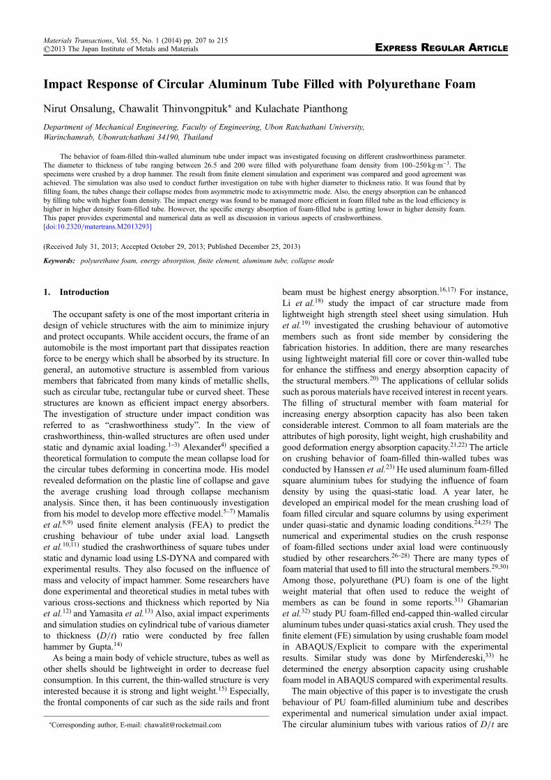
The PU foam used in this study is a mixture of twochemical substances; i.e., Polyol and Isocyanate. They weremixed in a ratio of 1 : 1 in liquid form. The mixture was, then,injected into the specimens with different densities. Themixture was allowed to expand inside the tube for about10min for completely expansion. The properties of PUfoam with different density were tested by cut each foamcolumn into 50 © 50 © 50mm3 cube. They were, then, testedunder uniaxial compression with a speed of 5mm·min¹1.Figure 1(a) shows the engineering stressstrain curve ofaluminium tubes obtained from standard test. The propertyof each density of PU foam is shown in Fig. 1(b).
2.3 Specimen preparation and finite element modelingThe specimens were performed on commercially available
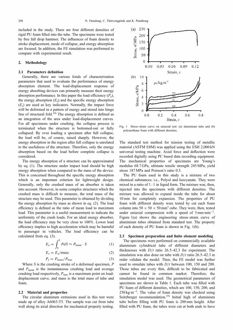
aluminium cylindrical tube of different diameters andthicknesses with D/t ratio 26.542.3 for experiment. Thesimulation was also done on tube with D/t ratio 26.542.3 inorder validate the model. Then, the FE model was furtherused to simulate tubes with D/t between 100, 150 and 200.Those tubes are every thin, difficult to be fabricated andcannot be found in common market. Therefore, thesimulation model was used. The geometrical parameters ofspecimens are shown in Table 1. Each tube was filled withPU foam of different densities, which are 100, 150, 200, and250 kg·m¹3. The value of foam density was checked usingSeitzberger recommendation.35) Initial high of aluminiumtube before filling with PU foam is 200mm height. Afterfilled with PU foam, the tubes were cut at both ends to have
Fig. 1 Stressstrain curve on uniaxial test: (a) aluminium tube and (b)polyurethane foam with different densities.
N. Onsalung, C. Thinvongpituk and K. Pianthong208
150mm height. Typical specimens before and after foam-filled are shown in Fig. 2(a). The specimens were made intriplicate in order to repeat the test. Therefore, there weretotally 60 pieces of specimen, including empty tubes.
The geometrical modeling was created in a commercial FEpackage code ABAQUS. The detail and configuration ofcontact boundary condition in FE are shown in Fig. 2(b). TheFE model is consisted of four parts i.e., top rigid plate,bottom rigid plate, aluminium tube, and PU foam column. Attop and bottom of tube the rigid plates were created with areference node at center. The element type of both rigidbodies are 4-node, bilinear quadrilateral R3D4. The tube andfoam are modeled with 8-node linear brick element C3D8R.Mesh independent of the FE model was made and optimummesh size was archived for tube and foam column. The foamcolumn was modeled to be crushable isotropic hardeningwith k = 1 and ¯p = 0,36) where k is the compression yield
stress ratio and defined as the ratio of initial yield stress inuniaxial compression to initial yield stress in hydrostaticcompression and ¯p is plastic Poisson’s ratio. The value offriction is 0.2 in every contact surfaces i.e., rigid plat andfoam, rigid plate and tube, tube and foam, according toSantosa’s recommendation.37)
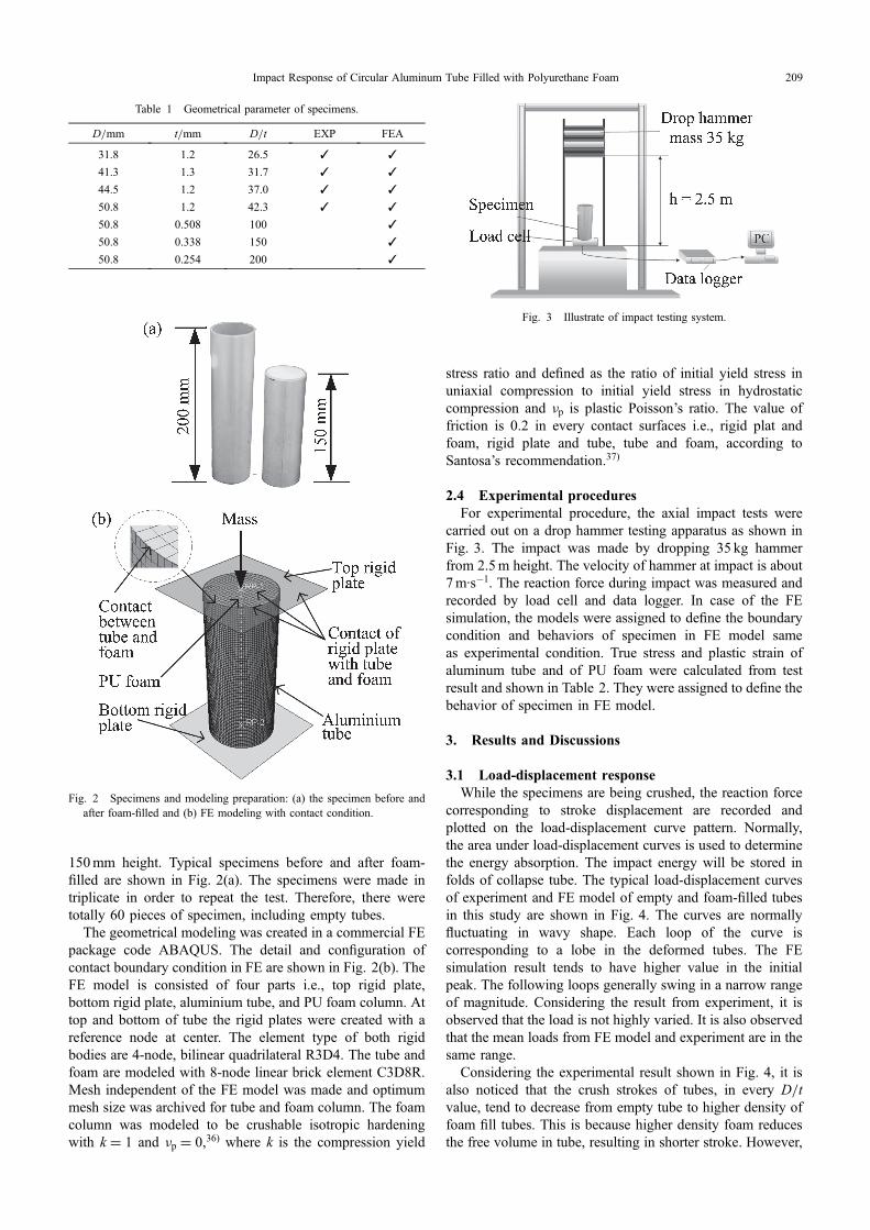
2.4 Experimental proceduresFor experimental procedure, the axial impact tests were
carried out on a drop hammer testing apparatus as shown inFig. 3. The impact was made by dropping 35 kg hammerfrom 2.5m height. The velocity of hammer at impact is about7m·s¹1. The reaction force during impact was measured andrecorded by load cell and data logger. In case of the FEsimulation, the models were assigned to define the boundarycondition and behaviors of specimen in FE model sameas experimental condition. True stress and plastic strain ofaluminum tube and of PU foam were calculated from testresult and shown in Table 2. They were assigned to define thebehavior of specimen in FE model.
3. Results and Discussions
3.1 Load-displacement responseWhile the specimens are being crushed, the reaction force
corresponding to stroke displacement are recorded andplotted on the load-displacement curve pattern. Normally,the area under load-displacement curves is used to determinethe energy absorption. The impact energy will be stored infolds of collapse tube. The typical load-displacement curvesof experiment and FE model of empty and foam-filled tubesin this study are shown in Fig. 4. The curves are normallyfluctuating in wavy shape. Each loop of the curve iscorresponding to a lobe in the deformed tubes. The FEsimulation result tends to have higher value in the initialpeak. The following loops generally swing in a narrow rangeof magnitude. Considering the result from experiment, it isobserved that the load is not highly varied. It is also observedthat the mean loads from FE model and experiment are in thesame range.
Considering the experimental result shown in Fig. 4, it isalso noticed that the crush strokes of tubes, in every D/tvalue, tend to decrease from empty tube to higher density offoam fill tubes. This is because higher density foam reducesthe free volume in tube, resulting in shorter stroke. However,
Table 1 Geometrical parameter of specimens.
D/mm t/mm D/t EXP FEA
31.8 1.2 26.5 ✓ ✓
41.3 1.3 31.7 ✓ ✓
44.5 1.2 37.0 ✓ ✓
50.8 1.2 42.3 ✓ ✓
50.8 0.508 100 ✓
50.8 0.338 150 ✓
50.8 0.254 200 ✓
Fig. 2 Specimens and modeling preparation: (a) the specimen before andafter foam-filled and (b) FE modeling with contact condition.
Fig. 3 Illustrate of impact testing system.
Impact Response of Circular Aluminum Tube Filled with Polyurethane Foam 209
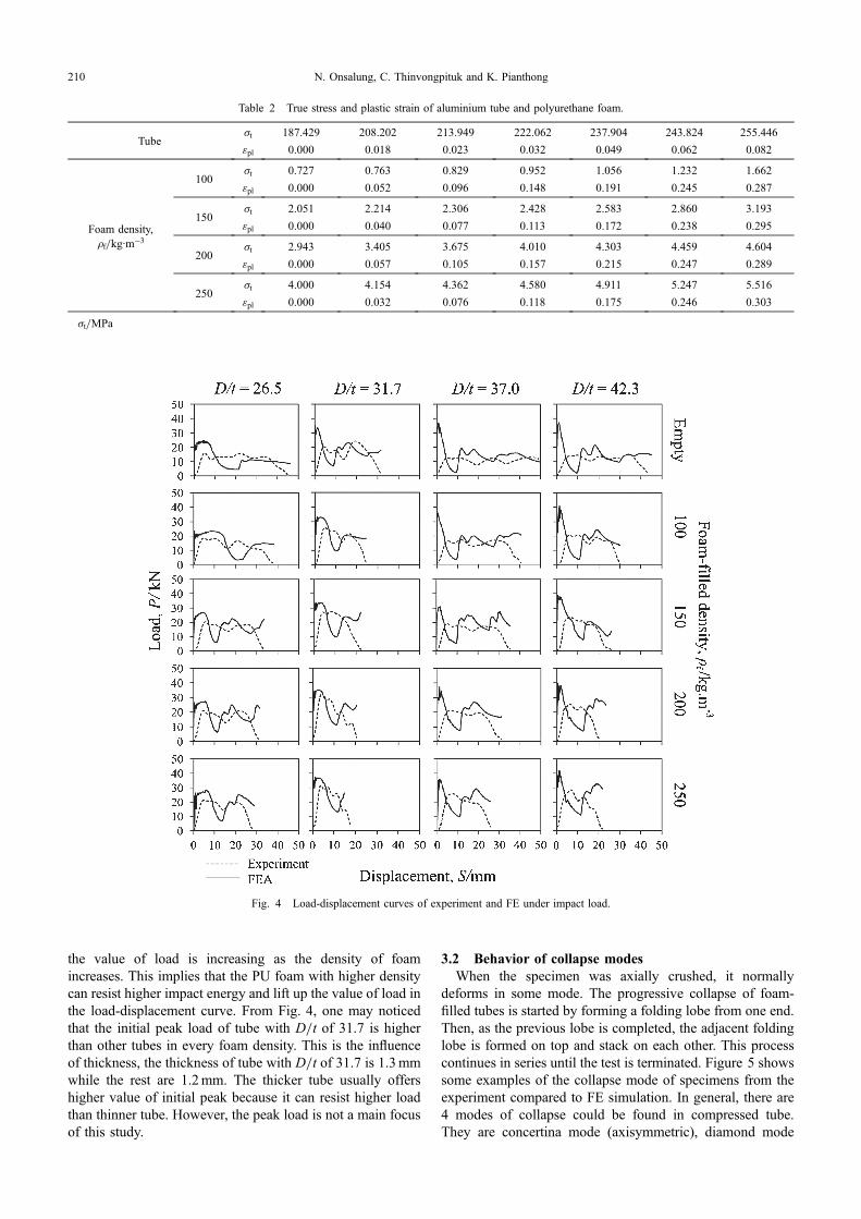
the value of load is increasing as the density of foamincreases. This implies that the PU foam with higher densitycan resist higher impact energy and lift up the value of load inthe load-displacement curve. From Fig. 4, one may noticedthat the initial peak load of tube with D/t of 31.7 is higherthan other tubes in every foam density. This is the influenceof thickness, the thickness of tube with D/t of 31.7 is 1.3mmwhile the rest are 1.2mm. The thicker tube usually offershigher value of initial peak because it can resist higher loadthan thinner tube. However, the peak load is not a main focusof this study.
3.2 Behavior of collapse modesWhen the specimen was axially crushed, it normally
deforms in some mode. The progressive collapse of foam-filled tubes is started by forming a folding lobe from one end.Then, as the previous lobe is completed, the adjacent foldinglobe is formed on top and stack on each other. This processcontinues in series until the test is terminated. Figure 5 showssome examples of the collapse mode of specimens from theexperiment compared to FE simulation. In general, there are4 modes of collapse could be found in compressed tube.They are concertina mode (axisymmetric), diamond mode
Table 2 True stress and plastic strain of aluminium tube and polyurethane foam.
Tube·t 187.429 208.202 213.949 222.062 237.904 243.824 255.446
¾pl 0.000 0.018 0.023 0.032 0.049 0.062 0.082
Foam density,µf/kg·m¹3
100·t 0.727 0.763 0.829 0.952 1.056 1.232 1.662
¾pl 0.000 0.052 0.096 0.148 0.191 0.245 0.287
150·t 2.051 2.214 2.306 2.428 2.583 2.860 3.193
¾pl 0.000 0.040 0.077 0.113 0.172 0.238 0.295
200·t 2.943 3.405 3.675 4.010 4.303 4.459 4.604
¾pl 0.000 0.057 0.105 0.157 0.215 0.247 0.289
250·t 4.000 4.154 4.362 4.580 4.911 5.247 5.516
¾pl 0.000 0.032 0.076 0.118 0.175 0.246 0.303
·t/MPa
Fig. 4 Load-displacement curves of experiment and FE under impact load.
N. Onsalung, C. Thinvongpituk and K. Pianthong210
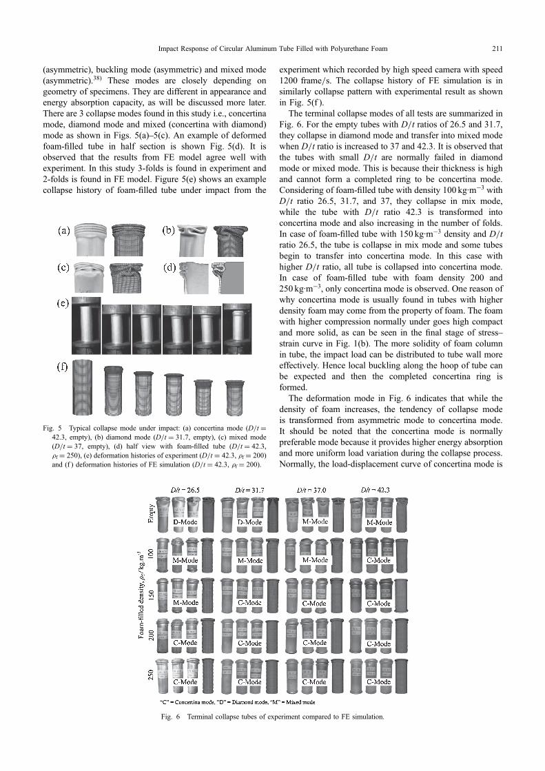
(asymmetric), buckling mode (asymmetric) and mixed mode(asymmetric).38) These modes are closely depending ongeometry of specimens. They are different in appearance andenergy absorption capacity, as will be discussed more later.There are 3 collapse modes found in this study i.e., concertinamode, diamond mode and mixed (concertina with diamond)mode as shown in Figs. 5(a)5(c). An example of deformedfoam-filled tube in half section is shown Fig. 5(d). It isobserved that the results from FE model agree well withexperiment. In this study 3-folds is found in experiment and2-folds is found in FE model. Figure 5(e) shows an examplecollapse history of foam-filled tube under impact from the
experiment which recorded by high speed camera with speed1200 frame/s. The collapse history of FE simulation is insimilarly collapse pattern with experimental result as shownin Fig. 5(f ).
The terminal collapse modes of all tests are summarized inFig. 6. For the empty tubes with D/t ratios of 26.5 and 31.7,they collapse in diamond mode and transfer into mixed modewhen D/t ratio is increased to 37 and 42.3. It is observed thatthe tubes with small D/t are normally failed in diamondmode or mixed mode. This is because their thickness is highand cannot form a completed ring to be concertina mode.Considering of foam-filled tube with density 100 kg·m¹3 withD/t ratio 26.5, 31.7, and 37, they collapse in mix mode,while the tube with D/t ratio 42.3 is transformed intoconcertina mode and also increasing in the number of folds.In case of foam-filled tube with 150 kg·m¹3 density and D/tratio 26.5, the tube is collapse in mix mode and some tubesbegin to transfer into concertina mode. In this case withhigher D/t ratio, all tube is collapsed into concertina mode.In case of foam-filled tube with foam density 200 and250 kg·m¹3, only concertina mode is observed. One reason ofwhy concertina mode is usually found in tubes with higherdensity foam may come from the property of foam. The foamwith higher compression normally under goes high compactand more solid, as can be seen in the final stage of stressstrain curve in Fig. 1(b). The more solidity of foam columnin tube, the impact load can be distributed to tube wall moreeffectively. Hence local buckling along the hoop of tube canbe expected and then the completed concertina ring isformed.
The deformation mode in Fig. 6 indicates that while thedensity of foam increases, the tendency of collapse modeis transformed from asymmetric mode to concertina mode.It should be noted that the concertina mode is normallypreferable mode because it provides higher energy absorptionand more uniform load variation during the collapse process.Normally, the load-displacement curve of concertina mode is
Fig. 5 Typical collapse mode under impact: (a) concertina mode (D/t =42.3, empty), (b) diamond mode (D/t = 31.7, empty), (c) mixed mode(D/t = 37, empty), (d) half view with foam-filled tube (D/t = 42.3,µf = 250), (e) deformation histories of experiment (D/t = 42.3, µf = 200)and (f ) deformation histories of FE simulation (D/t = 42.3, µf = 200).
Fig. 6 Terminal collapse tubes of experiment compared to FE simulation.
Impact Response of Circular Aluminum Tube Filled with Polyurethane Foam 211
more uniform than other modes. As the result, the meancrushing load is high compared to peak load and helps toreduce deceleration while impacting. This has been con-firmed by many investigators such as Andrews et al.38) andPled et al.39) who indicated that the concertina mode is betterthan other modes and higher specific energy absorption thanthe diamond mode. In addition, the study of Gupta et al.40)
also revealed that the crushing load of concertina mode ishigher than diamond mode in the specimen with samegeometry and boundary condition. On the crash behavior,concertina mode is the better for body tolerance in respectto reducing of acceleration and deceleration of human body.It is postulated that PU foam which filled in tube helpsdistributing impact load to the tube wall more effective,resulting more uniform mode and higher number of folds.This implies that one may achieve preferable mode(concertina mode) and increase number of folds by fillingtube with PU foam. Considering the FE model shown inFig. 6, it is observed that the FE results of collapse modes areagreed well with experimental results.
3.3 Effect of foam filled on crashworthiness parameterThe crashworthiness parameters were calculated with
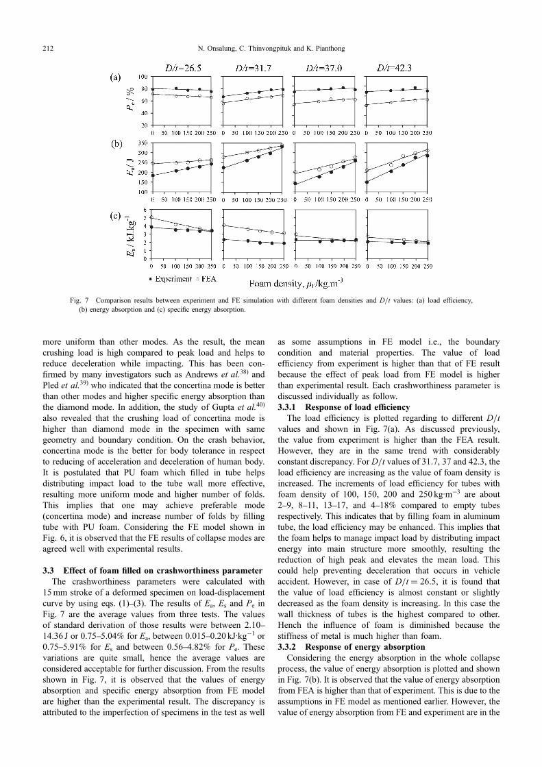
15mm stroke of a deformed specimen on load-displacementcurve by using eqs. (1)(3). The results of Ea, Es and Pe inFig. 7 are the average values from three tests. The valuesof standard derivation of those results were between 2.1014.36 J or 0.755.04% for Ea, between 0.0150.20 kJ·kg¹1 or0.755.91% for Es and between 0.564.82% for Pe. Thesevariations are quite small, hence the average values areconsidered acceptable for further discussion. From the resultsshown in Fig. 7, it is observed that the values of energyabsorption and specific energy absorption from FE modelare higher than the experimental result. The discrepancy isattributed to the imperfection of specimens in the test as well
as some assumptions in FE model i.e., the boundarycondition and material properties. The value of loadefficiency from experiment is higher than that of FE resultbecause the effect of peak load from FE model is higherthan experimental result. Each crashworthiness parameter isdiscussed individually as follow.3.3.1 Response of load efficiency
The load efficiency is plotted regarding to different D/tvalues and shown in Fig. 7(a). As discussed previously,the value from experiment is higher than the FEA result.However, they are in the same trend with considerablyconstant discrepancy. For D/t values of 31.7, 37 and 42.3, theload efficiency are increasing as the value of foam density isincreased. The increments of load efficiency for tubes withfoam density of 100, 150, 200 and 250 kg·m¹3 are about29, 811, 1317, and 418% compared to empty tubesrespectively. This indicates that by filling foam in aluminumtube, the load efficiency may be enhanced. This implies thatthe foam helps to manage impact load by distributing impactenergy into main structure more smoothly, resulting thereduction of high peak and elevates the mean load. Thiscould help preventing deceleration that occurs in vehicleaccident. However, in case of D/t = 26.5, it is found thatthe value of load efficiency is almost constant or slightlydecreased as the foam density is increasing. In this case thewall thickness of tubes is the highest compared to other.Hench the influence of foam is diminished because thestiffness of metal is much higher than foam.3.3.2 Response of energy absorption
Considering the energy absorption in the whole collapseprocess, the value of energy absorption is plotted and shownin Fig. 7(b). It is observed that the value of energy absorptionfrom FEA is higher than that of experiment. This is due to theassumptions in FE model as mentioned earlier. However, thevalue of energy absorption from FE and experiment are in the
Fig. 7 Comparison results between experiment and FE simulation with different foam densities and D/t values: (a) load efficiency,(b) energy absorption and (c) specific energy absorption.
N. Onsalung, C. Thinvongpituk and K. Pianthong212
same trend. It is observed that the value of energy absorptionis increased as the value of foam density is increasing.
For tubes with D/t = 26.5, the value of energy absorptionis increased by 12.8, 19, 23.9, and 31.6% for 100, 150, 200and 250 kg·m¹3 foam density respectively compared toempty tube. In case of tube with D/t = 31.7, the energyabsorption is increased by 15.8, 24, 31.6 and 47% when filledwith foam of 100, 150, 200 and 250 kg·m¹3 density. In caseof tube with D/t = 37, the energy absorption is increasedby 23.3%, 40%, 58.4%, 80.8% and for the D/t = 42.3, isincreased by 36.8, 58.6, 83.7, and 89.5% when filled withfoam of 100, 150, 200 and 250 kg·m¹3 foam densityrespectively. From the previous discussion, it is noticed thatthe increment of the energy absorption is higher in thinnertubes (higher D/t). This is because the influence of foam isdominant in thin tube. From Fig. 7(b) it is also noticed thatthe increment of Ea is also related to the change of failuremode. Considering the specimens with D/t = 26.5, theempty tube failed in diamond mode and changed to mixedmode after filled with foam density of 100150 kg·m¹3 andchanged further to concertina mode with density of foam200250 kg·m¹3. As the collapse modes changed fromdiamond mode to mixed mode and to concertina mode, thevalue of Ea is increasing. For tube with D/t = 26.5, it isobserved that the value of Ea is increasing about 1819% and2432% when modes change from diamond mode to mixedand from mixed mode to concertina mode respectively. It isalso observed for tube with D/t = 31.7 that the empty tubefailed in diamond mode and changed to mixed mode fordensity of 100 kg·m¹3 and then further changed to concertinamode after filled with density of 150, 200 and 250 kg·m¹3.Similarly, as the D/t = 31.7 tube changes its mode fromdiamond mode to mixed mode to concertina mode, it isobviously seen that the value of Ea is also increasing. For thistube, the value of Ea is increasing about 24 and 47% whenmodes change from diamond mode to mixed and from mixedmode to concertina mode respectively. Similar phenomenoncan be observed for tubes with D/t = 37.0 and 42.3. Theincrements of their Ea are about 4080% and 3790%respectively when their modes change from mixed modeto concertina mode. Therefore, it could be concluded thatthe tubes with foam filled could be changed their collapsemodes to concertina modes and higher energy absorptioncan be expected because concertina mode normally provideshigher Ea.3.3.3 Response of specific energy absorption
The relationship of specific energy absorption and value offoam density is shown in Fig. 7(c). It is observed that thevalue of specific energy absorption from FE simulation isslightly higher than experiment, but still in a similar pattern.In general, it is observed that the value of the specific energyabsorption of foam filled tube is slightly decreased as thevalue of foam density increases. Considering the experimen-tal results, it is found that the value of specific energyabsorption of foam filled tube, compared to empty tube, isdecreased by 310%, 716%, 218%, and 018% for foamdensity of 100, 150, 200 and 250 kg·m¹3 respectively. Thisimplies that, although the additional foam can enhance theenergy absorption capacity of tube, it also adds more weightto the structure.
3.4 Crashworthiness prediction using FE modelAs it is observed in the previous topics that the FE models
provided good agreement to the experimental results. Hence,the model was used for further investigation on tubes withD/t of 100, 150 and 200. The geometrical detail of tubes inFE model is shown in Table 1. They were filled with foamof the same densities, which are 0, 100, 150, 200 and250 kg·m¹3. The test procedure is similar to that explained intopic 2.3 and 2.4.
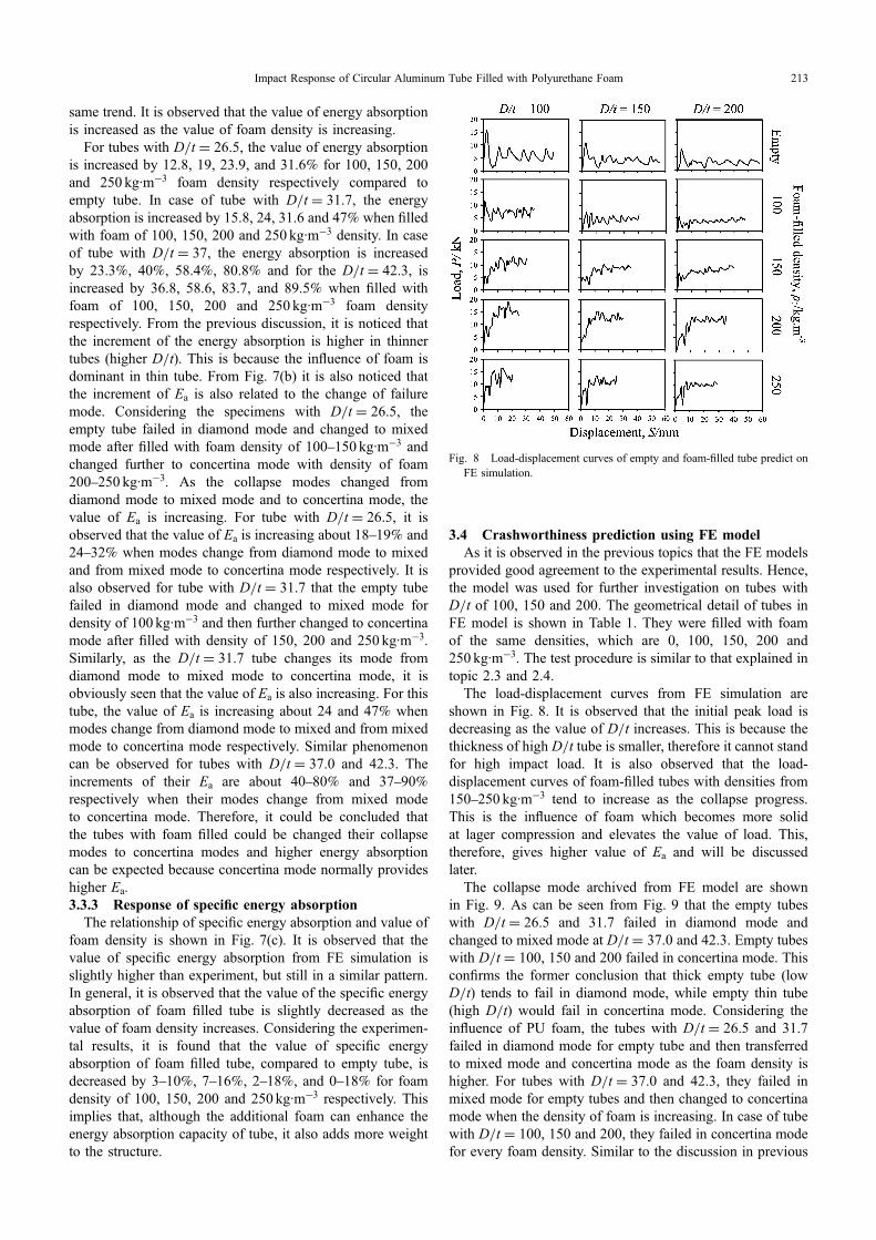
The load-displacement curves from FE simulation areshown in Fig. 8. It is observed that the initial peak load isdecreasing as the value of D/t increases. This is because thethickness of high D/t tube is smaller, therefore it cannot standfor high impact load. It is also observed that the load-displacement curves of foam-filled tubes with densities from150250 kg·m¹3 tend to increase as the collapse progress.This is the influence of foam which becomes more solidat lager compression and elevates the value of load. This,therefore, gives higher value of Ea and will be discussedlater.
The collapse mode archived from FE model are shownin Fig. 9. As can be seen from Fig. 9 that the empty tubeswith D/t = 26.5 and 31.7 failed in diamond mode andchanged to mixed mode at D/t = 37.0 and 42.3. Empty tubeswith D/t = 100, 150 and 200 failed in concertina mode. Thisconfirms the former conclusion that thick empty tube (lowD/t) tends to fail in diamond mode, while empty thin tube(high D/t) would fail in concertina mode. Considering theinfluence of PU foam, the tubes with D/t = 26.5 and 31.7failed in diamond mode for empty tube and then transferredto mixed mode and concertina mode as the foam density ishigher. For tubes with D/t = 37.0 and 42.3, they failed inmixed mode for empty tubes and then changed to concertinamode when the density of foam is increasing. In case of tubewith D/t = 100, 150 and 200, they failed in concertina modefor every foam density. Similar to the discussion in previous
Fig. 8 Load-displacement curves of empty and foam-filled tube predict onFE simulation.
Impact Response of Circular Aluminum Tube Filled with Polyurethane Foam 213
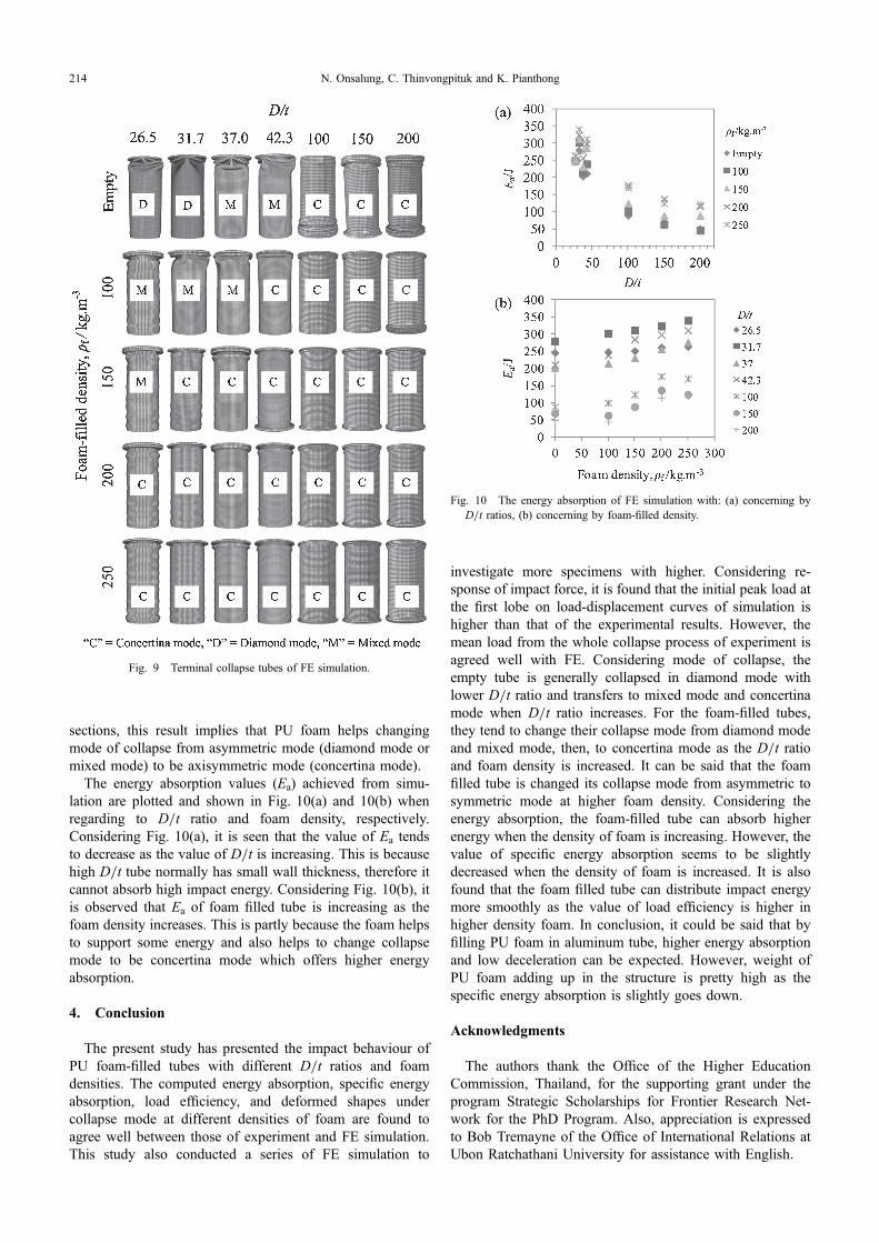
sections, this result implies that PU foam helps changingmode of collapse from asymmetric mode (diamond mode ormixed mode) to be axisymmetric mode (concertina mode).
The energy absorption values (Ea) achieved from simu-lation are plotted and shown in Fig. 10(a) and 10(b) whenregarding to D/t ratio and foam density, respectively.Considering Fig. 10(a), it is seen that the value of Ea tendsto decrease as the value of D/t is increasing. This is becausehigh D/t tube normally has small wall thickness, therefore itcannot absorb high impact energy. Considering Fig. 10(b), itis observed that Ea of foam filled tube is increasing as thefoam density increases. This is partly because the foam helpsto support some energy and also helps to change collapsemode to be concertina mode which offers higher energyabsorption.
4. Conclusion
The present study has presented the impact behaviour ofPU foam-filled tubes with different D/t ratios and foamdensities. The computed energy absorption, specific energyabsorption, load efficiency, and deformed shapes undercollapse mode at different densities of foam are found toagree well between those of experiment and FE simulation.This study also conducted a series of FE simulation to
investigate more specimens with higher. Considering re-sponse of impact force, it is found that the initial peak load atthe first lobe on load-displacement curves of simulation ishigher than that of the experimental results. However, themean load from the whole collapse process of experiment isagreed well with FE. Considering mode of collapse, theempty tube is generally collapsed in diamond mode withlower D/t ratio and transfers to mixed mode and concertinamode when D/t ratio increases. For the foam-filled tubes,they tend to change their collapse mode from diamond modeand mixed mode, then, to concertina mode as the D/t ratioand foam density is increased. It can be said that the foamfilled tube is changed its collapse mode from asymmetric tosymmetric mode at higher foam density. Considering theenergy absorption, the foam-filled tube can absorb higherenergy when the density of foam is increasing. However, thevalue of specific energy absorption seems to be slightlydecreased when the density of foam is increased. It is alsofound that the foam filled tube can distribute impact energymore smoothly as the value of load efficiency is higher inhigher density foam. In conclusion, it could be said that byfilling PU foam in aluminum tube, higher energy absorptionand low deceleration can be expected. However, weight ofPU foam adding up in the structure is pretty high as thespecific energy absorption is slightly goes down.
Acknowledgments
The authors thank the Office of the Higher EducationCommission, Thailand, for the supporting grant under theprogram Strategic Scholarships for Frontier Research Net-work for the PhD Program. Also, appreciation is expressedto Bob Tremayne of the Office of International Relations atUbon Ratchathani University for assistance with English.
Fig. 9 Terminal collapse tubes of FE simulation.
Fig. 10 The energy absorption of FE simulation with: (a) concerning byD/t ratios, (b) concerning by foam-filled density.
N. Onsalung, C. Thinvongpituk and K. Pianthong214
REFERENCES
1) S. R. Guillow, G. Lu and R. H. Grzebieta: Int. J. Mech. Sci. 43 (2001)21032123.
2) G. M. Nagel and D. P. Thambiratnam: Int. J. Impact. Eng. 32 (2006)15951620.
3) I. W. Hall, O. Ebil, M. Guden and C. J. Yu: J. Mater. Sci. 36 (2001)58535860.
4) J. M. Alexander: J. Mech. Appl. Math. 13 (1960) 1015.5) W. Abramowicz and N. Jones: Int. J. Impact. Eng. 2 (1984) 263281.6) A. A. Singace, H. Elsobky and T. Y. Reddy: Int. J. Solids Struct. 32
(1995) 35893602.7) A. A. Singace and H. Elsobky: Int. J. Solids Struct. 33 (1996) 3517
3538.8) A. G. Mamalis, D. E. Manolakos, M. B. Ioannidis, P. K. Kostazos and
C. Dimitriou: Thin Wall. Struct. 41 (2003) 891900.9) A. G. Mamalis, D. E. Manolakos, N. B. Ioannidis and P. K. Kostazos:
Int. J. Crashworth. 10 (2005) 505513.10) M. Langseth, O. S. Hopperstad and A. G. Hanssen: Thin Wall. Struct.
32 (1998) 127150.11) M. Langseth, O. S. Hopperstad and T. Berstad: Int. J. Impact. Eng. 22
(1999) 829854.12) A. A. Nia and J. H. Hamedani: Thin Wall. Struct. 48 (2010) 946954.13) M. Yamashita, M. Gotoh and Y. Sawairi: J. Mater. Process. Tech. 140
(2003) 5964.14) N. K. Gupta and Venkatesh: Thin Wall. Struct. 44 (2006) 290300.15) M. R. Bambach: Thin Wall. Struct. 48 (2010) 440452.16) C. Hackmair, E. Werner and M. Pönisch: Comput. Mater. Sci. 28
(2003) 540547.17) H. Ning, G. M. Janowski, U. K. Vaidya and G. Husman: Compos.
Struct. 80 (2007) 8291.18) Y. X. Li, Z. Q. Lin, A. Q. Jiang and G. L. Chen: Mater. Des. 24 (2003)
177182.19) H. Huh, K. P. Kim, S. H. Kim, J. H. Song, H. S. Kim and S. K. Hong:
Int. J. Mech. Sci. 45 (2003) 16451660.
20) K. S. Lee, Y. J. Yang, W. C. Hwang and I. Y. Yang: Trans. Nonferr.Metal. Soc. China 19 (2009) s276s279.
21) W. Abramowicz: Thin Wall. Struct. 41 (2003) 91107.22) L. Aktay, A. K. Toksoy and M. Güden: Mater. Des. 27 (2006) 556565.23) A. G. Hanssen, M. Langseth and O. S. Hopperstad: Int. J. Mech. Sci. 41
(1999) 967993.24) A. G. Hanssen, M. Langseth and O. S. Hopperstad: Int. J. Impact. Eng.
24 (2000) 475507.25) A. G. Hanssen, M. Langseth and O. S. Hopperstad: Int. J. Impact. Eng.
24 (2000) 347383.26) M. Miyazaki and H. Negishi: Mater. Trans. 44 (2003) 15661570.27) Y. Yamada, T. Banno, Z. K. Xie and C. Wen: Mater. Trans. 46 (2005)
26332636.28) W. Y. Yan, E. Durif, Y. Yamada and C. Wen: Mater. Trans. 48 (2007)
19011906.29) Z. Ahmad and D. P. Thambiratnam: Compos. Struct. 87 (2009) 186
197.30) D. Karagiozova, M. Alves and N. Jones: Int. J. Impact. Eng. 24 (2000)
10831115.31) S. A. Meguid, M. S. Attia and A. Monfort: Mater. Des. 25 (2004) 183
189.32) A. Ghamarian and M. T. Abadi: Thin Wall. Struct. 49 (2011) 743752.33) L. Mirfendereski, M. Salimi and S. Ziaei-Rad: Int. J. Mech. Sci. 50
(2008) 10421057.34) S. Poonaya, U. Teeboonma and C. Thinvongpituk: Thin Wall. Struct.
47 (2009) 637645.35) M. Seitzberger, F. G. Rammerstorfer, R. Gradinger, H. P. Degischer, M.
Blaimschein and C. Walch: Int. J. Solids Struct. 37 (2000) 41254147.36) A. Ghamarian and M. T. Abadi: Thin Wall. Struct. 49 (2011) 743752.37) S. P. Santosa, T. Wierzbicki, A. G. Hanssen and M. Langseth: Int. J.
Impact. Eng. 24 (2000) 509534.38) K. R. F. Andrews, G. L. England and E. Ghani: Int. J. Mech. Sci. 25
(1983) 687696.39) F. Pled, W. Yan and C. Wen: 5th Australasian Congress on Applied
Mechanics, (2007) pp. 178183.40) N. K. Gupta and Nagesh: Int. J. Mech. Sci. 48 (2006) 210223.
Impact Response of Circular Aluminum Tube Filled with Polyurethane Foam 215