impedance heating systems - indeeco most of the existing thermal insulation. ... exxon research...
TRANSCRIPT

Impedance Heating Systems
C88

Table of Contents
An Impedance Heating System is a unique, safe and proven method for electric pipeline tracing and heating. The pipe actually becomes the heating element when low AC voltage is applied to it by a special, custom designed transformer.
INDEECO can provide single source responsibility for design, hardware and start-up assistance for an impedance heating system to heat gasses or fluids flowing through yourpipeline. It can also be used over a wide range of temperatures to prevent freezing in coldweather, maintain fluidity of viscous materials, raise the temperature of heat sensitive materialsor maintain gas temperatures up to 1600o F.
The Hynes Electric Heating Company designed and fabricated electric heating equipment fordemanding industrial applications since 1926. Based upon field experience with thousands of successful world-wide installations, Hynes was a recognized leader in electric process andpipeline heating applications for temperature sensitive liquids and gases.
In 1987, INDEECO purchased the Hynes Electric Heating Company. Together, INDEECO and Hynes represent many years of experience in electric process heating. We look forwardto putting that experience to work for you in your next impedance heating application.
Introduction
Benefits and Advantages . . . . . . . . . . . . . . . . . . . . . . . . . . . . . . . . . . . . . . . . . . . . . . . . . . . . .1
How Impedance Heating Works . . . . . . . . . . . . . . . . . . . . . . . . . . . . . . . . . . . . . . . . . . . . . . .2
Customers and Applications . . . . . . . . . . . . . . . . . . . . . . . . . . . . . . . . . . . . . . . . . . . . . . . . . .3
Impedance Heating Applications . . . . . . . . . . . . . . . . . . . . . . . . . . . . . . . . . . . . . . . . . . . . .4-6
Engineering Application Guide . . . . . . . . . . . . . . . . . . . . . . . . . . . . . . . . . . . . . . . . . . . . . .7-9
The Impedance Heating System . . . . . . . . . . . . . . . . . . . . . . . . . . . . . . . . . . . . . . . . . . .10-11
Application Data Sheet . . . . . . . . . . . . . . . . . . . . . . . . . . . . . . . . . . . . . . . . . . . . . . . . . . . . .12
Limited Warranty
Benefits of Impedance Heating
Benefits and Advantages
1
Low Voltage Operation — All systems operate at less than 30 Volts, many at 10 Volts or below.INDEECO systems meet or exceed the requirementsof the National Electrical Code (Article 427), assuringsafe operation.
Uniform Heating — Because the entire pipeeffectively acts as the heating element, heat is generated uniformly throughout its entire length and circumference without hot spots.
Simplicity — The impedance method takes thecomplexity out of pipeline heating. A few basiccomponents comprise the entire heating system.Installation is simple; it can be installed without disturbing most of the existing thermal insulation.
Wide Temperature Range — INDEECO has pioneered the use of impedance heating for applications ranging from below freezing to 1600
oF. It is often the only viable option for high
temperature pipeline heating.
Close Control — Thermocouple sensors placedalong the pipeline provide precise, uniform temperature control. Optional SCR controls givethe ability to achieve control within ± 1
oF.
Low Cost — Installation costs are kept to a minimum by the inherent simplicity of the system.Likewise, maintenance is virtually eliminated; manysystems operate unattended. Energy costs are lowbecause the required energy is concentrated in thepipe and efficiently heats the fluid or gas travelingthrough it.
No Burnouts — When the pipe becomes theheating element, burnouts and failures associatedwith electrical resistance tapes and cables are eliminated.
No External Fluids — Pipeline heating with steam or high temperature fluids introduces a high degree of complexity and a potential hazard.Impedance heating accomplishes the same resultin a simple, straightforward manner.
No Leaky Jackets — With impedance heating,you won’t have leaky steam lines, cracked steamtraps, pump failures or frozen return pipes.
No Hot Spots — Impedance heating eliminatesthe danger of overheating temperature-sensitivematerials (asphalt, chocolate, heavy syrups) becausehot spots associated with conventional pipe tracingare eliminated.
No Routine Maintenance — Routinemaintenance is eliminated, along with the replacement parts and production shutdowns associated with such maintenance.
Advantages Over Conventional Methods

2
How Impedance Heating Works
The basic concept of impedance heating is quitesimple: Terminals are attached to each end ofthe pipe, and a low voltage current is passedthrough it. In other words, the pipe acts as its own heating element.
The explanation of how impedance heating worksis a bit more complex. Traditionally, electric heat isgenerated by passing current through a wire that ispurely resistive. This is how electrical resistance tapeor cable tracing produces heat. With the impedancemethod, heat is generated by combining three different effects:
1. The pipe acts as a resistor, much the same as a wire in the traditional method. The electricalresistance of the pipe depends upon its length,composition and wall thickness.
2. When heating a straight length of pipe, it is necessary to attach a power cable to oneend (see Figure 1). The cable is normally laidon the pipe’s insulation jacket. The current flow in a typical impedance system is enoughto set up a significant magnetic field aroundthe cable. Since most pipes are made frommagnetic materials, steel being the most common, the magnetic field interacts with the pipe, producing the second component of heat, skin effect/proximity effect.
3. A 60 hertz power source produces a magneticfield that changes direction 60 times per second. The electrical inertia of the pipe relative to these changes produces a hysteresis effect, which is the third source of heat in the impedance method.
Taking all of these effects into account, INDEECOdesigns and furnishes a hardware package to gener-ate the proper amount of heat for a given pipelinesystem. That package consists of the following:
• Power Transformer — A transformer, fed froma commercial power source, produces the correctvoltage to give adequate heat and safe operatingconditions. Furnished in its own enclosure, thetransformer has multiple taps to fine-tune thevoltage output in the field. Output voltages rangefrom 1 to 30 Volts.
• Control Panel — Pipe temperature is controlledby a thermocouple sensor attached to the pipe.The standard control panel includes a processtemperature controller, magnetic contactor and all necessary pilot lights, relays, fuses, etc.Optional solid-state proportional control, with fully modulated SCR, is also available for more precise temperature control.
• Terminal Plates with Cable Lugs — Terminalplates are supplied for field attachment to thepipe and low voltage power cabling.
• Flange Isolation Kits — In order to confine the electrical current to the section of pipe being heated, INDEECO can furnish isolation kits consisting of an isolator gasket for each endof the pipe and isolator bolts with proper washersto secure the gasket and mating flanges. Notethat standard field-furnished flanges are used with the isolation kits. No special flange treatmentis necessary.
PowerCable
ThermocoupleLeads (attach
to control panel) Control Panel
NEMA 3RTransformer
Cable Lug
INLET
ThermocoupleConnection
TerminalPlate
Flanges
Isolator BoltSteel Washer
Isolator Washer
Isolator Gasket
StandardPipeline
InsulationJacket
Strap
Figure 1

Impedance systems heat a wide variety of gases,liquids and viscous materials which are stored,pumped and processed in many different industries and applications. Impedance heating can be used in three basic ways:
Cold Start: Heat is applied to increase fluidity ofstatic, viscous materials so they can be pumped.Typical materials include asphalt, molasses andheavy fuel oils.
Maintain Temperature or Pipe Tracing: Heat is applied to a liquid or gas flowing through a pipeto offset heat losses. Typical applications includefreeze protection or maintaining the fluidity of viscous materials.
Temperature Rise: Heat is applied to a liquid orgas flowing through a pipe in order to raise itstemperature between the inlet and outlet of theheated pipe. Typical applications include heatingcorrosive liquids or high temperature process air.
Customers and Applications
A partial list of customers and applications are shown below.
CUSTOMER MATERIAL HEATED TEMP (oF) PIPE LENGTH (FT)
Allied Chemical Corp. Coal Tar Pitch 450 131Allied Fibers Corp. Superheated Steam 1040 70Aluminum Co. of America Pitch 170 1155American Hoechst Corp. Polypropylene 400 22Amoco Oil Co. Fuel Oil 280 891Amoco Oil Co. Zinc Chloride 700 53Arco Oil & Gas Co. Crude Oil 150 15700Atlantic Richfield Salt Water 40 802Barnard & Burk Sulphur 265 70Bethlehem Steel #6 Fuel Oil 280 891Bouligny Co. Superheated Steam 845 34British Petroleum Alaska Water 40 611Brown & Root Inc. Crude Oil 50 1270Catalytic Corp. Liquid Pentasulfide 752 2Celotex Corp. Asphalt 400 1760Certain Teed Corp. Asphalt 480 52Chemtex Inc. Polymer 536 52Chevrolet Motor Div. Catalyst 70 770Colgate Palmolive Inc. Sulphur 300 165E.I. Dupont Process Gas 575 170Emery Industries Stearic Acid 160 370Ethyl Corp. Powdered Catalyst 450 53Exxon Research & Engineering Heavy Fuel Oil 950 552Exxon Synthetics Inc. Coal Slurry 370 558Fisher Scientific Co. Resin & Hardener Mix 194 40Fortifiber Corp. Asphalt 500 250Foster Wheeler Corp. Paraffin 60 1020H.K. Ferguson Pitch 735 100Hershey Foods Corp. Chocolate 110 377Honeywell Air 1200 114Inland Steel Co. Fuel Oil 160 8500Intalco Aluminum Air/Tar Mixture 500 52International Paper Wax 185 520Kaiser Aluminum Co. Coal Pitch 380 500Kitchens of Sara Lee Nulomoline 100 325Koppers Co. Enamel Filling 375 85Layton Engineering #6 Fuel Oil 125 550M & M Mars Co. Chocolate 120 1400Medusa Cement Co. #6 Fuel Oil 150 700Mobil Pipe Line Inc. Wax 145 93Monsanto Montar 752 230N.L. Industries Magnesium Chloride 1300 95National Starch & Chemical Wax 210 300National Starch & Chemical Wax/Resins 100 1400Nestlé Chocolate 110 263Pillsbury Haagen Dazs Sweeteners 120 180PolyOne Elastomers & Performance Additives Oil 180 350Procon, LTD. Sulphur 285 890Rohm & Haas Process Vapor 1100 26Shell Chemical Co. Process Fluid 500 41Sherwin Williams, Inc. Pitch 500 140South Carolina Electric Sulphur 110 1350SPEC Process Engineering & Construction Inc. Isocyanate 120 400Stauffer Chemical Co. Phosphorous Pentasulfide 707 30Sun Oil Company Sulphur 290 485Tennessee Eastman Polymers 320 1165Trimount Bituminus Asphalt 325 425Union Electric Co. Wax 212 612Upjohn Isocyanate 120 476Vulcan Material Caustic 750 360Western Electric Co. Thermoplastic Rubber 300 900Yabucoa Sun Oil Co. Pitch 400 2300
3

Power Generating UtilityApplication: To maintain heavy fuel oil at 140
oF
and facilitate pumping from barges to storagetanks and return lines. The application requiredcold start recovery capabilities to heat up the fueloil in case of station shut down. Pipe size diametersranged from 10” to 24” with a combined pipelength of almost two miles. Impedance heatingwas selected because critical importance wasplaced upon system reliability, maintenance andoperating costs.
Design: Seven impedance heating systems wererequired. To conserve heat, pipe lines, gaskets andflanges were covered with 2” of insulation andsheathed with 16 gauge aluminum.
Food ProcessingApplication: To maintain the temperature ofchocolate and sweetener at 120
oF as it flows
through 16 gauge, sanitary 304 stainless steel tubing lines. Impedance heating was selectedbecause of the temperature sensitive characteristicsof the material and the importance of uniform temperature control to the quality of the product.Pipe lengths for different lines varied from 128 feetto 420 feet. The sanitary environment required frequent washdown of the control panel.
Design: Three individual impedance heating systems were required, rated 1.5, 2 and 3 KVA.Standard on-off control with operational RTD inputwas selected. Stainless steel, NEMA 4X controlpanel enclosures with a viewing window to monitoractual process variables were supplied to meet thefrequent washdown requirements.
Metal ProcessingApplication: To heat a mixture of air, water vaporand tar particles up to 400
oF at a flow rate of
5,750 lbs/hr. Ten inch diameter stainless steel ductswere used in the first phase of the process wherethe mixture was heated up to 400
o F. Carbon steel
ducts were used in the second phase of the processto maintain the final temperature. Impedance heating was the most cost effective method for this application which included one additionalrequirement of heating the duct work up to 500
oF
during a cleaning phase where residual tar on theduct walls melt, allowing it to simply flow out ofthe duct work.
Design: Three individual impedance heating systems rated 36, 171 and 176 KVA were used in this application. Full SCR controls were used for each system to provide precise temperaturecontrol. Special weld terminals were also supplieddue to the high secondary transformer currents.
Plastic ProcessingApplication: To control, monitor and heat to temperature within 16 hours, a 4,800 foot, 2”schedule 40, 304L stainless steel pipe containing a sludge mixture. The impedance heating controlpanel needed computer interface with auxiliaryoutputs for alarm indication.
Design: Six identical 11 KVA impedance heatingsystems were supplied for this job. The solid-stateproportional control panel was capable of remotesignal input and temperature indication and includedammeters, voltmeter and auxiliary control circuitsource. Under actual operating conditions, theimpedance heating system exceeded the applicationrequirements by providing a recovery time of only14 hours, which was of critical importance to theprocess, allowing greater production rates.
Impedance Heating Applications
Impedance heating used to facilitate pumping of fuel oil frombarges to storage tanks at power generating utility.
4

Chemical ProcessingApplication: A highly corrosive material must be heated through a 630
o F temperature rise with
a flow rate of 160 lbs/hr. Conventional processheating methods were too costly and could not withstand the high temperature corrosion for anyreasonable period of time. Impedance heating provided the answer.
Design: Customer supplied, heavy wall, Inconelpipe became the heating element and transportingdevice in this impedance heating system. A mid-point connection system was selected to eliminatethe need for electrical isolation at the pipe ends.
Test EquipmentApplication: To preheat high temperature air from800
o F to 1200
oF at a flow rate of 20 lbs/min.
Impedance heating was selected over the moreconventional direct heating methods because of thelow flow rate and high outlet temperature. A lowpressure drop was also a requirement of the appli-cation. The impedance heating system easily metthis requirement since the pipe became the heat-ing element, offering no obstruction to the hightemperature air flowing through the pipe.
Design: One 75 KVA impedance heating systemwas used. The design was a completely packagedunit including an Incoloy pipe in a multipass con-figuration, transformer, control panel with fullinstrumentation and high temperature insulation.
AerospaceApplication: Constant 600
oF air at pressures up
to 3,000 psi was needed at three different locations,including two wind tunnels and one model prepa-ration area. Distances from the air storage area tothe point of use ranged from 100 ft. to 200 ft.Impedance heating was chosen as the most costeffective way of preheating the piping from thestorage tank to the three use points.
Design: Initial heating of the air in the storagetank was performed by two 400 KW resistanceheaters. Three individual 20 KVA impedance heating systems were then used to maintain thetemperature of the air as it passed through theschedule 160 carbon steel piping which was selectedbecause of its suitability for such high pressureapplications. To minimize heating costs, all aboveground piping was thermally insulated and somepiping was buried underground with a fiberglasspolyester weatherproof coating.
Impedance Heating Applications
Packaged impedance heating system for test equipment application. (System cabinet enclosure was removed for photography.)
5
Impedance heating used to heat high temperature, highpressure air for aerospace application.
Impedance Heating Applications
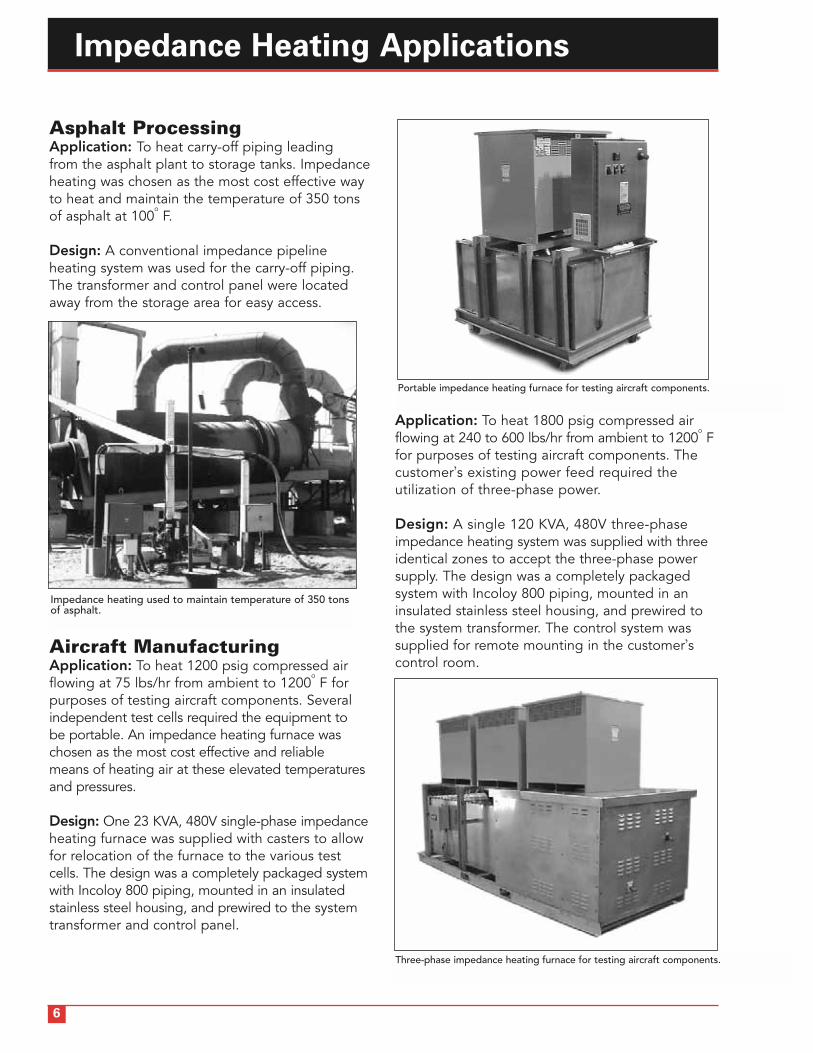
Asphalt ProcessingApplication: To heat carry-off piping leading from the asphalt plant to storage tanks. Impedanceheating was chosen as the most cost effective wayto heat and maintain the temperature of 350 tonsof asphalt at 100
oF.
Design: A conventional impedance pipeline heating system was used for the carry-off piping.The transformer and control panel were locatedaway from the storage area for easy access.
Aircraft ManufacturingApplication: To heat 1200 psig compressed airflowing at 75 lbs/hr from ambient to 1200
oF for
purposes of testing aircraft components. Severalindependent test cells required the equipment to be portable. An impedance heating furnace waschosen as the most cost effective and reliable means of heating air at these elevated temperaturesand pressures.
Design: One 23 KVA, 480V single-phase impedanceheating furnace was supplied with casters to allowfor relocation of the furnace to the various testcells. The design was a completely packaged systemwith Incoloy 800 piping, mounted in an insulatedstainless steel housing, and prewired to the systemtransformer and control panel.
Application: To heat 1800 psig compressed airflowing at 240 to 600 lbs/hr from ambient to 1200
oF
for purposes of testing aircraft components. Thecustomer’s existing power feed required the utilization of three-phase power.
Design: A single 120 KVA, 480V three-phase impedance heating system was supplied with threeidentical zones to accept the three-phase powersupply. The design was a completely packagedsystem with Incoloy 800 piping, mounted in aninsulated stainless steel housing, and prewired tothe system transformer. The control system wassupplied for remote mounting in the customer’scontrol room.
Impedance heating used to maintain temperature of 350 tonsof asphalt.
6
Portable impedance heating furnace for testing aircraft components.
Three-phase impedance heating furnace for testing aircraft components.

End-Point ConnectionThe end-point electrical connection is best suited forcomplex piping systems where multiple branches or“tees” are installed. There is no need to electricallybalance the system, as with a mid-point connection,which makes installation much easier.
Mid-Point ConnectionElectrical isolation is not required at the pipe endsfor this connection. Twice the length of pipe canbe heated over an end-point system at the samesecondary voltage, because the pipe is divided atthe mid-point. This connection is best suited forstraight or simple pipe runs where the electricalmid-point can be easily determined.
Engineering Application Guide
Electrical Pipe Connections and DesignsThere are two basic types of impedance heating electrical connections. These are the end-point and mid-point connections. Simplified drawings illustrating these two connections for a pipe and cable design are shown in Figures 2 and 3.
9999
TRANSFORMER
SECONDARY CABLE
CONTROL PANEL
ISOLATIONFLANGE
9999
TRANSFORMER
SECONDARY CABLE
CONTROL PANEL
MIDPOINT CABLE
7
Figure 2 - Pipe and Cable Design with End-Point Electrical Connection
Figure 3 - Pipe and Cable Design with Mid-Point Electrical Connection

Engineering Application Guide
Piping Circuitry DrawingsA customer supplied isometric piping layout drawingwill enable INDEECO to show recommended isolationpoints, electrical connections and cable runs.
The isometric drawing shown in Figure 4 represents atypical design for a piping arrangement with end-pointconnections. The overall length of the pipe in this system is 160 feet. The dotted lines represent returncables.
8
TE
TIC
TSH
TAH
TRANSFORMER
TE
Figure 4 - Isometric Layout Drawing
PIPE
CABLE
ISOLATION KIT(ELECTRICAL BREAK)
FLANGE
TERMINAL PLATE
THERMAL ELEMENTS
LEGEND

Engineering Application Guide
9
Impedance heating will maintain or raise the temperature of virtually any gas or liquid in either a flowing or static condition. Since the pipe is actually the heating element, maximumoperating temperatures are only limited by thepipe’s thermal characteristics.
Although the hardware for an impedance heatingsystem is simple to understand and operate, over25 interrelated application variables have to beconsidered during the initial design stage in orderto select the appropriate system hardware. Toeffectively deal with the complex mathematics,INDEECO has developed an exclusive computerdesign program.
To design each system efficiently, our engineeringdepartment needs certain information. Using thisinformation, the design output is generated by the computer program which is then used in theselection of the appropriate hardware.
Customer Input InformationThe following information is required for ALLPIPELINE HEATING applications:
Pipe Size: Pipe sizes range from 3/4” to 24” IPSand up to 36” for alloy materials. For carbon steel,we request the IPS pipe size and schedule number.For alloy pipe, we request outside diameter andwall thickness.
Pipe Material: Materials include carbon steel,stainless steel, nickel, Incoloy, Inconel, Monel,Hastelloy and Duranickel. Note: Copper, aluminumand other high electrically conductive materialscannot be used. Non-conductive materials, such as plastic pipe, are also unsuitable.
Pipe Length: This is virtually unlimited; however,short runs of a few feet are usually impractical, andlong runs of over several hundred feet may requiremultiple systems. An accurate system pipe lengthis very important to the impedance design.Inaccurate measurements or estimated pipelengths can result in a system that does not perform as designed.
Insulation Type and Thickness: The thermal insulation required on all heated pipes for energyefficiency varies in thickness and insulating properties. This information is needed to accuratelydetermine heat loss and required KVA for theimpedance heating system. Heat loss informationcan be provided by the customer or developed by INDEECO.
Ambient Temperature: The minimum andmaximum ambient temperatures to which thepipeline will be exposed.
Maintenance Temperature: This is the temperature at which the pipe is to be maintainedand is often the same temperature as the processmaterial in the pipe.
The following information is required for COLDSTART or TEMPERATURE RISE applications:
Specific Heat, Specific Gravity, Latent Heat ofFusion, and Melting Point: This data is requiredfor the static process material in the pipe at thetime of cold start-up.
Heatup Time: This is the desired and/or available amount of time in hours to bring theprocess material in the pipe up to the maintenancetemperature from ambient temperature.
Inlet Temperature: The fluid or gas temperatureentering the pipe.
Outlet Temperature: The required fluid or gastemperature at the outlet discharge.
Flow Rate: The fluid or gas mass flow rate inlbs/hr.

The Impedance Heating System
System HardwareThe standard INDEECO impedance heating systemincludes a control panel with on/off temperaturecontrol, system transformer, thermocouple sensor,electrical termination hardware and isolation kits, if required.
Standard Hardware
Control Panel — The standard control panel is a contactor controlled system with on/off processtemperature control.
This control panel includes the following components built into a NEMA 12 enclosure:
• Electronic process temperature controller withthermocouple input and digital temperature indicator
• Electronic high-limit/overtemperature controllerwith manual or automatic reset and thermocoupleinput
• 2-pole definite purpose controlling contactor• Control circuit transformer with fused secondary• Door interlocking disconnect switch• Heater circuit fusing• Illuminated ON/OFF pilot switch• “OVERTEMPERTURE” indication pilot light
Each INDEECO control panel is designed and custom-built in conformance with NEMA and UL standards.
System Transformer — A step down systemtransformer designed for the appropriate KVA rating of the impedance heating system is mounted in a ventilated NEMA 3R enclosure.
Custom-built INDEECO transformers are in conformance with NEMA and UL standards specifically for impedance heating service.
The skin temperature of INDEECO transformers is well within OSHA limits, so they can be locatedwithin reach of personnel.
The INDEECO multi-tap design allows for fieldadaptation to different pipe lengths.
Cable — INDEECO can supply selected coppercable with the appropriate terminations for systems.
Thermocouple Sensor — Standard Type J thermocouples are designed to be customermounted directly to the outside diameter of the pipe, under the thermal insulation.
Isolation Kits — Each impedance heating circuit is designed to be electrically uniform from end to end. For layouts with “tees” where currentdivides, and where grounded equipment is connected to the pipes, isolation kits are providedfor installation at the customer flanges. Each isolation kit provides a flange gasket, a set of non-conductive bolt sleeves and washers and the required steel washers and nuts. Standard isolation kits are used for process temperatures up to 450
oF.
10

The Impedance Heating System
11
Electrical TerminationHardware — Standard termination hardware includesstainless steel or copper-platedcarbon steel terminal plates,sized and shaped for weldingto the pipe. Crimped or boltedconnectors are provided forfield cable attachment. Speciallydesigned perforated plates areoffered for high temperatureapplications.
Special OptionsHardware for the standard INDEECO impedanceheating system can be upgraded or modified toinclude any of the following special options:
Solid State Proportional Control PanelThe SCR controlled system offers precise temperature control up to ± 1
oF.
Built-in control components consist of:• Temperature controller with thermocouple
input and digital temperature indication• Electronic high-limit/overtemperature
controller with manual or automatic reset and thermocouple input
• Phase angle fire, single-phase SCR with softstart (current limit)
• Control circuit transformer with fused secondary
• Illuminated ON/OFF pilot switch• Fan/filter assembly as required for heat
dissipation• 2-pole definite purpose safety contactor• Door interlocking disconnect switch• Heater circuit fusing
Optional control components consist of:• Remote signals and/or interlocks• Volt meter• Ammeter
Temperature SensorsINDEECO systems can be designed to operatewith optional temperature sensors, including Type K thermocouples or RTD’s.
Epoxy Encapsulated TransformersEpoxy encapsulation is available to protect thecopper transformer windings for applications in corrosive environments.
Control Panel EnclosuresNEMA 4 and NEMA 4X control panel enclosuresare available for applications with high humidity,washdown requirements, or corrosive environments.
System Transformer EnclosuresTransformers are available with stainless steel, copper free aluminum or fiberglass reinforcedenclosures for special or corrosive environments.NEMA 4 transformer enclosures are also available.
System Start-UpINDEECO provides a start-up manual with everyimpedance heating system. This includes infor-mation on: The hardware, how to install isolationkits and terminal plates, how to run and makecable connections, the start-up procedure, a checklist and a troubleshooting guide.
On-Site Assistance — Extended WarrantyA recommended option is to have a trainedINDEECO field service person supervise the initial start-up. Our technician will make sure theimpedance heating system is installed and operatingproperly by making on-site recommendations during the initial start-up of the system. Use ofINDEECO field start-up assistance will extend theStandard INDEECO Limited Warranty to 24 monthsfrom the date the system is placed in service.

Application Data Sheet
12
Date Job Reference
Company Name
Address
City State Zip
Customer Contact
Phone No. Fax No.
E-Mail Address
Submitted By (if different than above)
Date Quote Required
IMPEDANCE PIPELINE HEATING
APPLICATIONPipe Diameter & Schedule Pipe Material Pipe Length (ft.)
Insulation Thickness (in.) Insulation Type “K” factor
Wind Velocity (MPH) Indoor ❒ or Outdoor ❒ Min./Max. Ambient Temperatures (oF) / .
Material to be heated Heat sensitive? YES ❒ or NO ❒
***PLEASE INCLUDE P&ID WITH SUBMITTAL OF QUOTE REQUEST.***
TEMPERATURE MAINTENANCE
Maintenance Temperature (oF)
TEMPERATURE RISE
Inlet Temperature (oF) Outlet Temperature (oF)
Initial heat up time required (hours) Product Flow Rate
Fluid Properties: Density or Specific Gravity at oF Specific Heat (BTU/Lb/oF) at oF
Melting Point (oF) Latent heat of fusion (BTU/Lb)
Describe how the impedance system is to be used:
Describe the process loop:
HEATER DESIGNRequired KW rating or heat duty (if known)
Available power volts, phase, cycle
Maximum allowable watt density (W/in2) or skin temperature (oF) on heater pipe
Heater environment: Non-hazardous Area ❒ or Hazardous Area ❒
If Hazardous Area: Class , Division , Groups , Ignition Temperature Code .
Special Items:
CONTROLSType: ON/OFF ❒ / SCR (modulated) ❒
Controls mounted: Local ❒ / Remote ❒
NEMA Type enclosure: 12 ❒ , 4 ❒ , 4X ❒ , With Purge? YES ❒ or NO ❒ , 7 ❒ (cast aluminum)
Control Panel Heating/Cooling Required? YES ❒ / NO ❒
Special Control Items:
425 Hanley Industrial CourtSt. Louis, MO 63144Ph: 314-644-4300Fax: 314-644-5332www.indeeco.com
Industrial Engineering and EquipmentCompany (INDEECO) products are warrantedagainst defects in workmanship, material, design,labeling and packaging. No other warranty,expressed or implied, written or oral, applies. No person other than an officer or the generalmanager of INDEECO is authorized to give anyother warranty or assume any liability.
Warranty Period: This warranty is effective for eighteen months from the date of shipment of the product fromINDEECO’s factory, or for twelve months from the date the product is first placed in service,whichever period lapses first.
Conditions of Warranty: INDEECO products must be installed, operatedand maintained in accordance with INDEECO’sinstructions. INDEECO is not liable for damage orunsatisfactory performance of the product resultingfrom accident, negligence, alteration, unauthorizedrepair, improper application or installation of theproduct, improper specifications or corrosion.INDEECO IS NOT LIABLE FOR ANY INCIDENTALOR CONSEQUENTIAL DAMAGES. Claims againstcarriers for damage in transit must be filed by thepurchaser with the carrier.
Remedy: The part or product in question should be returnedfreight prepaid, to:
INDEECO425 Hanley Industrial CourtSt. Louis, Missouri 63144
Attention: Return Goods Manager
If after receipt of the product and the claim,INDEECO finds to its reasonable satisfaction thatthe product is defective in workmanship, material,design, labeling or packaging, the product will berepaired or replaced or the purchase price refundedat INDEECO’s option. There will be no charge tothe purchaser for parts or labor. Removal and reinstallation of the product, and shipment of theproduct to INDEECO for repair or inspection shallbe at the purchaser’s risk and expense.
THE REPAIR, REPLACEMENT OR REFUND PROVIDED FOR IN THIS LIMITED WARRANTY ISTHE EXCLUSIVE REMEDY OF THE PURCHASER.THIS WARRANTY IS EXPRESSLY IN LIEU OF ANYOTHER WARRANTIES, EXPRESSED OR IMPLIED,INCLUDING ANY WARRANTY OF MERCHANT-ABILITY OR FITNESS FOR A PARTICULAR PURPOSE. THERE ARE NO WARRANTIES WHICHEXTEND BEYOND THE TERMS OF THIS LIMITEDWARRANTY.
Limited Warranty

2.5M090488-1750-80-3
INDUSTRIAL ENGINEERING & EQUIPMENT CO.
425 HANLEY INDUSTRIAL COURTST. LOUIS, MO 63144
314-644-4300Fax: 314-644-5332www.indeeco.com