implementation and performance evaluation of route...
TRANSCRIPT

Implementation and Per formance Evaluation of Route Optimization in Mobile IP
By
Maoyu Wang
A thesis submitted to the Faculty of Graduate Studies and Research
in partial fulfillment of the requirements for the degree of
Master of Science
Ottawa-Carleton Institute for Computer Science
School of Computer Science
Carleton University Ottawa, Ontario
Nov 1, 2001
Copyright 2001, Maoyu Wang

II
The undersigned hereby recommend to
the Faculty of Graduate Studies and Research acceptance of the thesis,
Implementation and Per formance Evaluation of Route Optimization in Mobile IP
Submitted by
Maoyu Wang
In partial fulfillment of the requirements for the degree of Master of Science of Information & System Science
Dr. Thomas Kunz (Thesis Supervisor)
Dr. Frank Dehne (Director, School of Computer Science)
Car leton University Nov 1, 2001

III
Abstract
With the convergence of two technological developments, wireless communication and
compact computer devices, mobility support in networks is more desirable than ever.
IETF provides two approaches to support the mobility in the current Internet
infrastructure. They are mobile IP and Mobile IP with Route Optimization, both of which
introduce new functional entities, the home agent, and the foreign agent, into the Internet.
The triangle routing existing in Mobile IP is a big defect in terms of resource
consumption and performance. Route Optimization overcomes the triangle routing in
basic Mobile IP but introduces more security requirements. In order to investigate
performance of Route Optimization, we explored different ways to implement Mobile IP
with Route Optimization and chose user space approach by C++ under Linux platform,
evaluated the performance and provided our enhancement to the Route Optimization
draft. We obtained quantitative efficiency evaluation results. Our conclusion is that user
space implementation is acceptable and a desirable way to implement Route
Optimization. The efficiency gain of Route Optimization will depend on the relative
location of the three entities: the mobile node, the home agent and the correspondent
node as well as the quality of communication links between the three entities. In most
case, the Route Optimization efficiency gain is great and can achieve 17 times in terms of
throughput as compared to basic Mobile IP, at the mean time, only 3% losses in terms of
throughput as compared to plain IP. To solve deployment difficulty in the plentiful
correspondent nodes, we proposed a Binary Exponential Backoff Algorithm (BEBA) to
relieve the home agent burden while a correspondent node does not equipped with Route
Optimization functionality. Our work provides a valuable sample of the implementation
of Route Optimization and gives out quantitative performance enhancement in Route
Optimization. It is a useful work for verifying Route Optimization draft and future
mobility deployment in the Internet.

IV
Acknowledgments
I would like to express my sincere gratitude to my thesis supervisor, Dr. Thomas Kunz
for his invaluable guidance, enthusiastic encourage and support in every stage of my
thesis research. This thesis represents a great deal of time and effort not only on my part,
but on the part of my supervisor. He introduces me the field of mobile networking and
provides me many opportunities for growth: from reading papers, writing a survey,
turning a ideas to implementation, to getting through the inevitable research setbacks, and
finishing the thesis. He opens the door for me to enjoy a research work. What I learn
from him will provide me with lifetime benefits. I consider myself luck to access his
supervision.
I am grateful to John Knox for his technical support, encourage and consideration.
Without his help, I would never have gotten the experimental setup and finished my
coding and my experiments. I also thank Michael Ostrowski for his explanation of the
previous work and suggestion to the new work.
Finally, I want to express my deepest feeling to my family. I am so grateful to my
husband, Tao Chen, for his love and encourage. His creative mind, technology
knowledge and skills in computer science provide me endless support during my study. I
especially thank my sister, Maoning Wang, for the deep discussion along the way. Her
creative idea, quick thinking, and smart personality inspire me through all these years. I
owe my thanks to my little son. His brightness always fresh my mind. Finally, I would
like to thank my mom and dad for their love, self-sacrifice, encouragement and support as
well as being a great role model in my life. Without their encourage, I would not
challenge myself and pursue new goals again and again. Without their support, my
graduate study is impossible. During the five years, without their dedicated care, my son
would not be so healthy and bright. I dedicate the thesis to my parents.
V
Contents List of Figures List of Tables 1 Introduction ....................................................................................................................1
1.1 Network Mobility.......................................................................................................1
1.2 Third Generation Mobile Networking .......................................................................2
1.3 Routing Techniques in Mobile Network....................................................................4
1.4 Motivation..................................................................................................................5
1.5 Objective....................................................................................................................6
1.6 Road Map...................................................................................................................6
2 Internet Host Mobility Review......................................................................................8
2.1 Overview....................................................................................................................8
2.2 Abstract Function of Internet Mobility ......................................................................9
2.3 Cellular IP................................................................................................................11
2.4 DNS Approach.........................................................................................................13
2.5 SIP Approach...........................................................................................................14
2.6 Mobile IPv4 .............................................................................................................15
2.6.1 Terminology used in Mobile IPv4.....................................................................15
2.6.2 Operation ...........................................................................................................16
2.6.3 Control Messages ..............................................................................................17
2.6.4 Security..............................................................................................................18
2.6.5 Problems with IETF Mobile IP Protocol ...........................................................18
2.7 Route Optimization in Mobile IPv4.........................................................................19
2.7.1 Why Route Optimization...................................................................................19
2.7.2 Binding Cache Maintenance Message...............................................................21
2.7.3 Smooth Handoffs...............................................................................................22
2.7.4 Security..............................................................................................................22
2.8 Mobile IPv6 .............................................................................................................23
2.9 IP Layer Mobility vs. TCP Layer or Application Layer Mobility ...........................24
2.10 Related Work .........................................................................................................25
VI
2.10.1 Route Optimization in NUS............................................................................26
2.10.2 Route Optimization in CMU ...........................................................................27
3 Mobile IP over L inux ...................................................................................................28
3.1 Mobile IP Converge into Existing TCP/IP Stack.....................................................28
3.1.1 TCP/IP Architecture..........................................................................................28
3.1.2 IP Layer Traffic Flow........................................................................................28
3.1.3 Related Control Message Types: UDP, ICMP..................................................29
3.1.4 Related Data Structures: Route Table, ARP Cache...........................................29
3.1.5 Related Traffic Control: Tunneling, Traffic Monitor........................................30
3.2 Linux ........................................................................................................................30
3.3 Three Implementation Models.................................................................................31
3.3.1 Kernel Space Model ..........................................................................................31
3.3.2 User Space Model ..............................................................................................33
3.3.3 User and Kernel Space Model ...........................................................................35
3.4 Linux Platform and Basic Mobile IP.......................................................................35
3.5 Linux Platform and Route Optimization..................................................................36
3.5.1 Route Optimization Requirements....................................................................37
3.5.2 Capturing Packets from the Linux Kernel .........................................................37
3.5.3 Our Approach: IP Firewall Packet Filter ...........................................................39
3.5.4 Data Exchange between Application and Kernel ..............................................40
3.6 Improvements to Mobile IP Protocol .......................................................................40
3.6.1 Binary Exponential Backoff Algorithm ............................................................40
3.6.2 Binding Cache Management Strategy ...............................................................42
4 Route Optimization Implementation..........................................................................44
4.1 Implementation and Environment............................................................................44
4.2 Binding Control Message Structure.........................................................................45
4.3 Mobile IP Packet Filter ............................................................................................47
4.3.1 ipchains..............................................................................................................48
4.3.2 IP Packet Filter ..................................................................................................48
4.4 Communication Between User Space and Kernel Space.........................................50
4.5 Set Tunnel ................................................................................................................51

VII
4.6 Timer Management ..................................................................................................53
4.7 Some Graphic Expression........................................................................................54
4.7.1 Class Relationship .............................................................................................54
4.7.2 Activity Diagrams..............................................................................................55
4.8 Basic Mobile IP Architecture...................................................................................55
4.9 Correspondent Node................................................................................................57
4.9.1 Architecture.......................................................................................................57
4.9.2 Data Structure....................................................................................................59
4.9.3 Control Flow......................................................................................................60
4.10 Home Agent ...........................................................................................................64
4.10.1 Architecture.....................................................................................................64
4.10.2 Data Structure..................................................................................................65
4.10.3 BEBA (Binary Exponenial Backoff Algorithm) Implementation...................66
4.10.4 Control Flow....................................................................................................67
5 Exper iment and Evaluation.........................................................................................71
5.1 Testbed.....................................................................................................................71
5.2 Functionality ............................................................................................................73
5.2.1 Traceroute..........................................................................................................73
5.2.2 Binding Update Experiment ..............................................................................73
5.3 Performance.............................................................................................................75
5.3.1 Evaluation Criteria.............................................................................................75
5.3.2 Benchmark.........................................................................................................75
5.3.3 Scenarios Design ...............................................................................................76
5.3.4 Experimental Data Process................................................................................77
5.3.5 Typical Case......................................................................................................77
5.3.6 Bandwidth and Performance .............................................................................80
5.3.6.1 CN ����������� � �������������������������� �"!$#&%'�����(�)#+*,��-�.�/(�0����!�1�.�23/54
.........80
5.3.6.2 CN 6�7�8�9�:�;�<"=�>�?3@�A�9(:)> ..............................................................................83
5.3.6.3 HA BDCFE�G5H�I JLK�H�M�N"G�M�O�P Q�R$S&TUK�M�G�H�S ...........................................................84
5.3.6.4 CN VDWFX�Y(Z�[]\L^�Z�_�` idth Degrading ...........................................................86
5.3.7 Location and Performance.................................................................................87
VIII
5.3.7.1 HA in the Middle............................................................................................88
5.3.7.2 CN in the Middle............................................................................................89
5.3.7.3 MN in the Middle...........................................................................................91
5.4 Result Analysis ........................................................................................................94
6 Conclusion and Future Work......................................................................................96
6.1 Contributions............................................................................................................96
6.1.1 Implementation of Route Optimization.............................................................97
6.1.1.1 Home Agent Traffic Monitoring ....................................................................97
6.1.1.2 Home Agent Binding Update Management ...................................................97
6.1.1.3 Correspondent Node Binding Updating .........................................................97
6.1.1.4 Correspondent Node Binding Cache Management ........................................97
6.1.1.5 Correspondent Node Traffic Control ..............................................................97
6.1.2 Evaluating Route Optimization Performance....................................................98
6.1.3 Supporting Mobility in IPv6..............................................................................98
6.1.4 Enhancing Route Optimization Protocol ...........................................................98
6.1.4.1 Binary Exponential Backoff Algorithm (BEBA) ...........................................98
6.1.4.2 Binding Cache Management Strategies..........................................................99
6.2 Conclusion ...............................................................................................................99
6.3 Future Work ...........................................................................................................100
Reference........................................................................................................................101
Appendix A IP Based Mobility Proposals..................................................................104
A.1 Sony Mobile IP Proposal ......................................................................................104
A.2 Columbia Mobile IP Proposal ...............................................................................105
A.3 LSR Mobile IP Proposal .......................................................................................107
A.4 IBM Mobile IP Proposal ......................................................................................108
Appendix B Multicast Support for Mobile Hosts......................................................109
B.1 Abstract Function and Architecture in Multicast Support.....................................109
B.2 Four Proposals for Multicast Support ...................................................................110
B.2.1 IETF Mobile IP Foreign Agent Based Multicast (Remote-Subscription
Multicast)..................................................................................................................110

IX
B.2.2 IETF Mobile IP Home Agent Based Multicast (Bi-Directional Tunnelling
Multicast)..................................................................................................................111
B.2.3 MOM Proposal (Mobile Multicast Protocol)..................................................113
B.2.4 MMA (Multicast by Multicast Agent) Proposal .............................................115
B.2.5 Multicast Summary.........................................................................................116
B.3 Route Optimization in Multicast Support for Mobile IP......................................117
B.4 Security in Multicast Support for Mobile IP.........................................................117
Appendix C Basic Mobile IP Code Guide..................................................................119
Appendix D Mobile IP with Route Optimization HOWTO.....................................122

X
List of Figures
Figure 1.1 Example of 3G-IP Network Architecture...................................................................................... 2
Figure 2.1: Triangle Routing........................................................................................................................ 19
Figure 3.1 Kernel Space Model .................................................................................................................... 33
Figure 3.2 User Space Model ....................................................................................................................... 34
Figure 3.3 Kernel Space Model .................................................................................................................... 35
Figure 4.1 Timer Structure......................................................................................................................... 533
Figure 4.2 Class Relationship .................................................................................................................... 544
Figure 4.3 Activity Diagram Graphic Expression...................................................................................... 555
Figure 4.4 Class Relationship in a Correspondent Node........................................................................... 588
Figure 4.5 Class cpd_update_t: Process Binding Update Message........................................................... 600
Figure 4.7 Class timer_t: Timer Management............................................................................................ 611
Figure 4.6 Class select_t: Receiving Binding Update Message................................................................... 62
Figure 4.8 Class cpd_mobile_t: a mobile node expires.............................................................................. 622
Figure 4.9 Class cpd_mobile_t: a mobile node is created.......................................................................... 633
Figure 4.10 Class Relationship in a Home Agent....................................................................................... 655
Figure 4.11 Class ag_update_t: Receive CN→MN Message..................................................................... 677
Figure 4.12 Class ag_update_t: Send Binding Update Message................................................................ 688
Figure 4.13 Class ag_reg_t: Set Traffic Monitor for a MN.......................................................................... 69
Figure 4.14 Class ag_reg_t: Registration Lifetime Expires......................................................................... 69
Figure 4.15 ip_fw.c: Enhancement to Support HA’s Traffic Monitor .......................................................... 70
Figure 4.16 ag_update_t: Obtain Traffic Monitor Message from Kernel .................................................. 700
Figure 5.1 Mobile IP with Route Optimization Experiment System Setup ................................................... 72
Figure 5.3 CN acbedgfih,acb jlk]m)dnfohnprq5h&s tvuxwzy&{|d}h&q f&y ....................................................................... 82
Figure 5.4 CN ~c���)�n�o�g�r�5�}� ���x���}�'�}�}� �U� ............................................................................................... 83
Figure 5.5 HA ����)�g�i�g�r�(�&� �v�x�z�&�|�&�}� �U� ................................................................................................ 85
Figure 6.6 CN ����)�g i¡g¢r£¤¡ th Degrading............................................................................................... 86
Figure 5.7 HA locates between CN and MN................................................................................................. 88
Figure 5.8 CN locates between HA and MN................................................................................................. 90
Figure 5.9 Route Optimization Efficiency (CN in the Middle) ................................................................... 911
Figure 5.10 MN locates between HA and CN............................................................................................... 92
Figure 5.10 Route Optimization Efficiency (MN moves from HA to MN) .................................................. 933
XI
List of Tables Table 5.1 MN and CN in the Same Sunnet, Varying HA ¥�¦�§)¨g©iªg«r¬¤ª} ® .................................................... 78
Table 5.2 MN and CN in the Same Subnet, Varying HA ¯�°�±³²|´�µ·¶)¸&¹5º .................................................... 78
Table 5.3 CN »c¼e½n¾o¿�»c¼ ÀlÁ]Âcà ¾&Ä)Å)½n¾o¿nÆrÃ5¿&Ç ÈvÉxÊzË&Ì|½}¿&à ¾}Ë�Íià ÎxÏnÐÑǤ½g¾iÊnÒ}ÏnÓÔÐ Õ .......................................... 82
Table 5.4 Only CN Öc×"ØÚÙ Û}ÜÞÝ)ßgÛiàgárÙ¤à}â ã�äxå�æ}ç|ß&à}Ù Û}æ .................................................................................. 83
Table 5.5 Only HA èé�êÚë ì&í)îÞïgìoðnñrë5ð&ò óvôxõzö&÷|ïUð&ë ì&ö .................................................................................. 85
Table 5.6 CN ølù]úcû ü}ýÞþ)ÿgü����rû���� ��� ���|ÿ��}û ü�� .......................................................................................... 86
Table 5.7 HA’s Position and the Associated Drop Rate............................................................................... 88
Table 5.8 HA Between the CN and MN........................................................................................................ 89
Table 5.9 CN’s Position and the Associated Drop Rate............................................................................... 90
Table 5.10 CN Between HA and MN............................................................................................................ 91
Table 5.11 MN’s Position and the Associated Drop Rate.......................................................................... 922
Table 5.12 MN Between HA and CN............................................................................................................ 93

Chapter 1 Introduction 1
Chapter 1
Introduction
With technological development and people’s dependence on the Internet, a new branch
in the network area, mobile networking, is becoming noticeable and develops quickly.
In the chapter, some basic concepts and issues pertaining to mobile networking are
introduced. From the discussion of the open issues, our motivation is drawn and our goal
is set.
1.1 Network Mobility
Mobile computing enjoys more popularity with the convergence of two technological
developments, portable computer or information access devices, and wireless
communication as well as the people’s dependency on the Internet day by day. Mobile
computing is also called mobile networking, which means that a user does not notice the
change of the host’s point of attachment, that is, the movement is transparent to
applications. The fact that mobile computing is more desirable than ever can be attributed
to two technology enhancements. Hardware research results in affordable, portable,
lower-power wireless computers such as laptops or personal digital assistants (PDAs).
Wireless technology improvements address some constrains such as lower bandwidth,
higher noise level and expensive access equipment in the wireless communication
environment. Besides the technology development, the demand from people is also an
important impetus to mobility support in the Internet. Users who get used to the services
received from a stationary host expect to receive the same or even more fascinating
services while they travel with their wireless information access device anywhere and
anytime. For example, an automatic piloting system can utilize the wireless access and
mobility support to plan a route and indicate traffic congestion dynamically during a trip.
However, mobility support is a non-trivial task because location tracking and routing
system reaction to the movement are two challenges in networking, especially in the
Internet’s TCP/IP suite. In order to provide an IP mobility solution, many research groups
and industrial partners are involved, such as the Internet Engineering Task Force (IETF),
the Third Generation Partnership Project (3GPP), and the Mobile Wireless Internet
Chapter 1 Introduction 2
Forum (MWIF). A general architecture for Third Generation Wireless Networking was
introduced by these efforts.
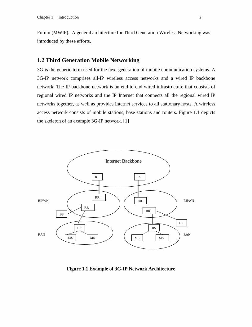
1.2 Third Generation Mobile Networking
3G is the generic term used for the next generation of mobile communication systems. A
3G-IP network comprises all-IP wireless access networks and a wired IP backbone
network. The IP backbone network is an end-to-end wired infrastructure that consists of
regional wired IP networks and the IP Internet that connects all the regional wired IP
networks together, as well as provides Internet services to all stationary hosts. A wireless
access network consists of mobile stations, base stations and routers. Figure 1.1 depicts
the skeleton of an example 3G-IP network. [1]
Figure 1.1 Example of 3G-IP Network Architecture
RIPWN
R R
RR
BS
BS
RR RR
BS
BS
MS
RR
MS MS MS RAN RAN
RIPWN
Internet Backbone

Chapter 1 Introduction 3
• Mobile Station (MS): the user mobile terminal that allows users to communicate.
• Base Station (BS): the radio access point to receive and send radio signals to MS.
• Radio Access Network (RAN): the wireless and back-haul infrastructure that
provides MSs with wireless access to the wired infrastructure.
• Regional Router (RR): a router working in a regional wired IP network, which
may use a wireless routing mechanism as the main routing scheme.
• Regional All-IP Wireless Network (RIPWN): the group of RR routers and wired
infrastructure, which mainly supports wireless networking.
• Router (R): a router working in the global wired IP backbone, which employs the
dominant IP routing protocols existing in the current Internet.
• Internet Backbone: global IP based wired backbone, which supports both the
fixed and the mobile networking.
3G aims to provide mobile users ubiquitous access to the integrated data, voice and
multimedia services of the Internet via their wireless terminals and appliances. The main
benefit of the 3G technologies such as W-CDMA will substantially enhance capacity,
quality and data rates. This enables the provision of advanced services transparently to
the end user. The gap between the wireless world and the Internet world will be bridged.
The development makes inter-operation apparently seamless regardless of the under lying
access technologies. [4]
Mobility in the 3G can be divided into macro mobility and micro mobility according to
the architecture. Mobility handled in a regional IP based wireless network is defined as
micro mobility. Mobility handled in the global Internet backbone or between two IP
based wireless networks is defined as macro mobility or global mobility [5]. Macro
mobility support and micro mobility support have different characteristics. Fast and
frequent hand off is the feature of Micro Mobility. In contrast, macro mobility needs to
cooperate with current existing IP routing mechanisms and to integrate the fixed and
mobile networking. For micro mobility support, the number of routers and the mobile
nodes are restricted to a limit range. For fast handoff and optimal routing, several mobile
routing protocols are proposed such as Cellular IP, HAWAII, IDMP, WIP [1]. In those
protocols, various routing techniques for the mobile communication network are
proposed. They provide different location tracking mechanisms and traffic delivery

Chapter 1 Introduction 4
mechanisms. All those micro mobility supporting protocols concentrate on the fact that
all nodes are mobile. They consider the impact of mobility on the routing system design
and the routing mechanism. However, as for the backbone wired Internet, it must support
the routing system for the large number of stationary nodes as well as mobile nodes.
Global Mobility has its own distinct characteristics. This thesis will focus on the global
mobility and discuss several proposed protocols that aim to be compatible with the
existing Internet infrastructure.
1.3 Routing Techniques in Mobile Network
To achieve mobility in a network, tracking location and adapting to changes in the
location of a mobile node are two crucial aspects. The routing system is able to deal with
the mobility in a network so that any movement is transparent to the application running
on two communicating hosts. One approach is to let all routers be aware of the movement
of any mobile hosts, cache the location information and propagate the movement in the
whole network. The routing system uses host-specific routes to forward data packets. In
this approach, the routing system will react to host movement and cache all hosts’
location information. The routing system consumes network resources in direct
proportion to the quantity and activity of mobile hosts. It is not a scalable and flexible
solution for global mobile networking. The advantages of the approach are route
optimality and smooth handoff. The routing protocol must respond to the movement
faster than the topological changes. Generally, the routing system approach is suitable for
the nonhierarchical architecture. In the architecture of third generation wireless
networking, the solution is suitable for the wireless access network.
The other approach is to limit the location tracking and movement adaptation to
particular entities and keep the routing system unaware of the movement. These
particular entities record movements and redirect data packets. The routing system will
forward data packets according to the hierarchical IP address architecture. Stationary
networking and mobile networking can coexist in a unified network. Scalability and
flexibility are the biggest advantages of the solution. It is suitable for the IP backbone
network. However, sub-optimal routes, resource consumption, and difficulty in managing
smooth handoff are the challenges in this solution.

Chapter 1 Introduction 5
1.4 Motivation
The routing protocols supporting micro mobility are optimized to provide fast and
smooth handoff within restricted geographical area. They concentrate on pure wireless
network and do not consider the great number of static hosts. In a global view, static
hosts are a large population group, which depend on Internet infrastructure. However,
TCP/IP architecture is designed under the assumption that the end hosts are connected to
the Internet statically and that changes in the topology are caused by faults or the addition
of new equipment. It is also assumed that these changes are infrequent. The IP address
serves as dual purposes. One is the identifier of the host. The other reflects the host’s
point of attachment. A fundamental concept of the Internet architecture is that each end
host has a unique network address, and network addresses form a hierarchy [2]. The
routing mechanism is based on this hierarchical structure and uses the IP address as the
directive to deliver an IP data packet. In the current TCP/IP suite, if a host moves from
one network to another network, its IP address must change. However, many applications
above TCP/IP use the IP address as the identifier. The IP address cannot be changed in
this sense. The Mobile IP IETF working group proposes Mobile IP as a promising
solution to solve the dilemma by applying two IP addresses to each mobile host. One IP
address serves as the identifier, called home address. The other IP address serves as the
directive of the point of attachment, which is used by the routing system to deliver data.
However, the problems existing in Mobile IP such as routing anomalies, faulty
congestion control, and lack of real transparency to the application are not desirable [3].
To solve the problem existing in basic Mobile IP, Route Optimization has been
developed by the IETF. Either Mobile IP or Mobile IP with Route Optimization is a
component of IP to provide mobility support at the IP layer. Any IP based network can
support mobility by applying Mobile IP or Mobile IP with Route Optimization. The
original IP routing scheme can work well without any disturbance. Any application above
the TCP/IP suite can be applied in a seamless manner.
Mobile IP and its Route Optimization are two promising solutions to global mobility and
occupy important positions in 3G networking. In basic Mobile IP or Mobile IP with
Route Optimization, packets addressed to a mobile node are delivered to a temporary
Chapter 1 Introduction 6
address assigned to the mobile node at its actual point of attachment by using regular IP
routing mechanism. The approach results in simple and scalable schemes that offer
global mobility. Mobile IP and its Route Optimization keep the original Internet IP
routing mechanism for static hosts by adding the home agent and foreign agent to provide
mobility support. Especially Mobile IP with Route Optimization, which eliminates the
triangle routing problem and reduces the network burden, can provide an efficient way to
combine fixed networking and mobile networking in a unified network. However, how
much efficiency gain is obtained in Route Optimization? Is it worth to overcome the
deployment difficulty that exists in Route Optimization? Is there any improvement can be
added into the Route Optimization protocol? The thesis addresses those and related
questions.
1.5 Objective
The main goals of our project are as follows:
• Providing an implementation of Mobile IP with Route Optimization under Linux
operating system by object oriented approach and investigating the problems
existing in the implementation such as intercepting data packets in a home agent,
updating binding cache, managing the binding cache and handling lack of
mobility support in a correspondent node.
• Comparing Mobile IP with Route Optimization to basic Mobile IP, obtaining
quantitative efficiency evaluation.
• Enhancing the Mobile IP with Route Optimization draft.
• Implementing the correspondent node’s function in the user space in order to
alleviate deployment difficulties.
• Providing a reference to the performance of other similar protocols with Route
Optimization such as Mobile IPv6, in which the Route Optimization is intrinsic.
1.6 Road Map
The thesis is organized into six parts. Chapter 2 surveys various approaches to support
mobility, especially in the Internet. Emphasis is placed on IP layer solutions such as
Chapter 1 Introduction 7
Mobile IP, Mobile IP with Route Optimization. Related implementation efforts are also
mentioned. Chapter 3 introduces three choices to implement the Mobile IP or Mobile IP
with Route Optimization as well as the relationship of Mobile IP with Route
Optimization and the TCP/IP protocol stack from the implementation point of view.
Chapter 4 describes the design and implementation details, which include packet
interception, Binding Update message management and Binary Exponential Backoff
Algorithm in a home agent, binding cache maintenance, binding cache management, and
data flow control in a correspondent node. Chapter 5 gives a quantitative evaluation of
the performance of Route Optimization as compared to basic Mobile IP and plain IP. It
also demonstrates that the efficiency gain of Route Optimization differs with network
situations and the location of associated entities. Chapter 6 draws our conclusions and
discusses future work.

Chapter 2 Internet Host Mobility Review 8
Chapter 2
Internet Host Mobility Review In order to support mobility in the Internet, many efforts have been made and various
proposals are provided. In this chapter, several representative approaches such as Mobile
IPv4, Route Optimization in Mobile IPv4, Mobile IPv6, Cellular IP, DNS approach, and
SIP approach are reviewed. At the end of this chapter, we also introduce related
implementations of Mobile IPv4 with Route Optimization.
2.1 Overview
In today’s Internet, an IP address has dual significance. One serves as an end host’s
identifier. The other acts as the routing directive. Mobile networking introduces a conflict
between the two functions. When an end host moves, its IP address should change to
reflect the new point of attachment to the network. However, the end host needs to keep
the original IP address to identify itself in the network. In order to solve the contradiction,
the two functions should be decoupled. One way is to find another identifier for the host,
and an IP address just serves as the routing directive. Another way is that we use two IP
addresses for each host. One IP address serves as end point identifier; another IP address
serves as routing directive. Many researchers have done a lot of work to provide mobility
in the Internet. Several approaches are proposed. IETF Mobile IPv4 [16,17] and Mobile
IPv6 [11,12] consider two IP addresses for each mobile end host. SIP approach [1,8] and
DNS approach [10] consider an email-like address or the domain name as the identifier.
Cellular IP [5,6,7] replaces IP routing with hop-by-hop routing. Mobile IPv4 and Mobile
IPv6 solve the mobility problem at the IP layer. Mobility is transparent to the TCP layer
and application layer. Users of mobile end hosts are unaware of the mobility. DNS
approach solves the mobility at the TCP layer. SIP solves the mobility at the application
layer. Mobility is not transparent to the application any more. Users are aware of the
mobility and anticipate the roaming process. Different proposals support mobility at
different network layers. Actually, mobility has widely affected all Internet layers, from
the physical layer to the application layer [13]. In this thesis, we will focus on the
influence on the packet routing. Although the mobility management can be handled at
Chapter 2 Internet Host Mobility Review 9
different layers, a mobility problem is a routing problem caused by a host’s movement.
Routing problems are solved at the IP layer. Therefore, the IETF Mobile IP solution has
been widely accepted as the most promising candidate for global mobility support. In this
chapter, we will introduce several approaches. However, emphasis is placed on the IETF
Mobile IPv4 and Route Optimization in Mobile IPv4.
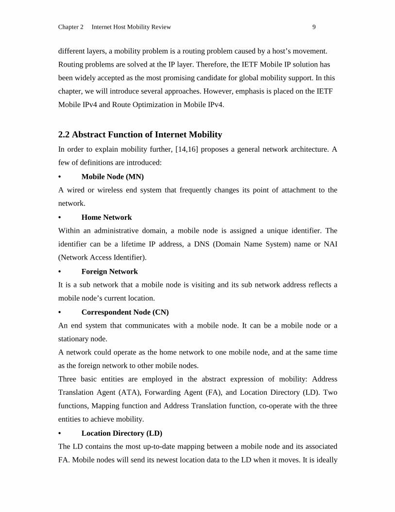
2.2 Abstract Function of Internet Mobility
In order to explain mobility further, [14,16] proposes a general network architecture. A
few of definitions are introduced:
• Mobile Node (MN)
A wired or wireless end system that frequently changes its point of attachment to the
network.
• Home Network
Within an administrative domain, a mobile node is assigned a unique identifier. The
identifier can be a lifetime IP address, a DNS (Domain Name System) name or NAI
(Network Access Identifier).
• Foreign Network
It is a sub network that a mobile node is visiting and its sub network address reflects a
mobile node’s current location.
• Correspondent Node (CN)
An end system that communicates with a mobile node. It can be a mobile node or a
stationary node.
A network could operate as the home network to one mobile node, and at the same time
as the foreign network to other mobile nodes.
Three basic entities are employed in the abstract expression of mobility: Address
Translation Agent (ATA), Forwarding Agent (FA), and Location Directory (LD). Two
functions, Mapping function and Address Translation function, co-operate with the three
entities to achieve mobility.
• Location Directory (LD)
The LD contains the most up-to-date mapping between a mobile node and its associated
FA. Mobile nodes will send its newest location data to the LD when it moves. It is ideally

Chapter 2 Internet Host Mobility Review 10
located at the home network of the mobile node. It can also be cached by correspondent
nodes.
• Translation Agent (ATA)
The ATA converts the mobile node’s identifier to the address of the FA associated with
the mobile node. The function that maps the identifier into a location address is an
Address Translation function (f). The process of Address Translation involves querying
the LD, obtaining the FA address, and using the FA address to send out the packets
destined to the mobile node.
• Forwarding Agent (FA)
The FA provides an access point through which mobile nodes can attach to the network.
It receives packets on behave of mobile node, and forwards the packets to mobile nodes.
FA’s address reflects the current location of a mobile node.
The function that reverses the location address into an identifier is a Forwarding function
(g). Ideally, the Forwarding function is implemented in the FA and the FA is co-located
with a mobile node.
A correspondent node that knows the identifier of a mobile node sends out a packet
destined to the identifier. Somewhere, during the route, there is an ATA. It translates the
identifier into the location address by querying the LD. After the packet leaves the ATA,
its destination address should be the location address. When the packet gets to the foreign
network, the FA resumes identifier as the destination address, and forwards the packet to
the mobile node.
How to arrange the LD, where to implement the ATA, how to propagate the location
information, and what kind of Address Translation mechanism used will depend on the
specific mobility proposals. There is always a trade-off between different choices.
No matter what kind of solution it is, a mobility management scheme should take care of
the following issues such as location detection, registration, configuration, dynamic
binding, and location management and handoff on need basis [1].
• Location Detection is a process by which a MN is aware of its movement and its
current point of attachment.
• Registration is a process by which a MN notifies its home network of its current
location.

Chapter 2 Internet Host Mobility Review 11
• Configuration is a process by which a MN updates its IP address to reflect its
current location.
• Dynamic Address Binding allows a MN to maintain a constant identifier
regardless of its point of attachment to the network.
• Location Management is responsible for updating the mapping between the
identifier and location and supporting location/redirect services to authorized users and
authorities.
• Handoff is a process that allows an established connection to continue when a
MN moves from one cell to another without interruptions in the connection.
2.3 Cellular IP
Cellular IP [5,6,7] is an IP solution based on cellular mobile system. It inherits the
advantages of the mobility management in cellular system such as passive connectivity
and handoff control, but it is designed on the IP paradigm. It is optimized for frequent
mobility and fast handoff in a restricted geographical area. It provides routing cache,
page cache to route an IP packet in a cellular network and cooperate with mobile IP to
route an IP packet in the global network.
A cellular IP network consists of a gateway, which connects the cellular network to the
Internet, and some base stations (BS), which serve as a wireless access point and route IP
packet from the gateway to mobile nodes or vice versa. An IP address in Cellular IP
serves as the identifier of a mobile node. Instead of using IP address as the routing
directive, the Routing Cache and the Page Cache are used in Cellular IP. The gateway is
the information convergent point in a Cellular IP network. Any packet transmitted by a
mobile node will be forward to the gateway. There are two directional data flows in
Cellular IP. Downlink packets are routed from the gateway to mobile nodes. Uplink
packets are routed from mobile nodes to the gateway. The intermediate base stations
forward the downlink or the uplink packets. The mobility management is integrated with
routing. In order to route the uplink packet, the gateway periodically broadcast a beacon
packet. The beacon packet will be flooded in the cellular network. A base station records
the interface that it receives the beacon packet and uses the interface to route a uplink
packet toward the gateway. At the same time, in order to route downlink packets, when a

Chapter 2 Internet Host Mobility Review 12
uplink packet which is transmitted by a mobile node is going through a base station, the
base station will record the IP address of the source mobile node and the interface over
which the packet entered the node. The mapping <IP address, Interface Num> about the
location information of mobile nodes forms the Routing Cache in a base station. In this
situation, regular data packets transmitted by mobile nodes are used to establish the
location information. Packets traveling toward the gateway are monitored and the
mapping between the sender’s IP address and incoming port are created. In the future,
packets addressed to the mobile node are routed along the reverse path, hop-by-hop by
these Routing caches [5]. If there is no data packet transmitted by a mobile node, an
empty IP packet can be transmitted to the gateway in order to maintain the location
mapping. However, only a small percentage of mobile nodes are transmitting or receiving
data packets while a large number of mobile nodes attach to a wireless network at a time.
Inheriting passive connectivity in the telephone cellular system, Page Caches are
established by sending paging-update packets periodically by idle mobile nodes. By
monitoring passing paging-update packets and by mapping the sender’s IP address to
incoming port, nodes in the access network create a reverse path for paging packet
destined to the mobile node. When IP packets arrive at the gateway, addressed to a
mobile node for which no up-to-date routing information, exists a paging packet is routed
along a reverse path taken by the paging-update packet from the idle mobile node to the
gateway. Upon receiving the paging packet, the mobile node will send a route-update
packet to gateway. Then, the mapping <IP address, Interface Num> will be inserted into
routing cache. IP packets are transferred to the mobile node by using the routing cache.
Smooth handoff is automatically ensured by the routing mechanism in Cellular IP. A
mobile node always initiates a handoff by redirecting its data packets from the old to new
base station when it approaches a new base station. When the first outgoing packet from
the mobile node to the gateway travels along the uplink, the Routing Cache in a node
records the mapping between the IP address of the mobile node and the node’s incoming
port. The next data packet destined to the mobile node will be transferred according to the
reverse path to arrive the mobile node’s new location.
Chapter 2 Internet Host Mobility Review 13
The routing, paging and handoff mechanisms in Cellular IP can efficiently handle the
mobility by a hop-by-hop basis in a local network. It is optimal for the frequent and fast
handoff.
2.4 DNS Approach
In the DNS approach[10], the DNS name of a MN is used as the identifier of this MN
instead of the home IP address. IP addresses fundamentally denote a point of attachment
in the Internet topology and say nothing about the identifier of a MN. Each time a MN
moves from a previous subnet to a new subnet, it obtains a new address to indicate its
current location. This updated location information will be sent to Domain Name System
(DNS). DNS will update its entry for this mobile node to form a mapping between the
name of the MN and the new IP address. When a CN wants to initialize a
communication, it sends an address resolution request to DNS. The DNS searches its
database to get the MN’s new IP address and sends it back to the CN. CN can send
packets to the MN according to the new IP address. The indirection occurs only when the
initial lookup is done via a control message (a DNS lookup). So, the DNS can be seen as
LD in the abstract mobility architecture. In this proposal, the DNS is the third party.
Three cases are considered in this approach:
• A MN initializes a conversation. No address lookup is needed. The CN will get
the location address by receiving the first packet.
• A CN initializes a conversation. CN will get the MN’s IP address by sending a
control message (a DNS lookup) to DNS.
• A MN moves during an active TCP. This is the main consideration in this
proposal. The architecture provides a new Migrate TCP option, included in SYN
segments, that identifies a SYN packet as part of a previous established connection,
rather than a request for a new connection. This Migrate option contains a token that
identifies a previously established connection on the same <destination address, port>
pair. The token is negotiated during initial connection establishment through the use of a
Migrate-Permitted option. After a successful token negotiation, TCP connections may be
uniquely identified by either their traditional <source address, source port, dest address,
dest port> 4-tuple or a new <source address, source port, token> triple on each host. A
Chapter 2 Internet Host Mobility Review 14
mobile node may restart a previously-established TCP connection from a new address by
sending a special Migrate SYN packet that contains the token identifying the previous
connection. The fixed host will than re-synchronize the connection with the mobile node
at the new end point. A migrated connection maintains the same control block and state
(with a different end point, of course), including the sequence number space, so any
necessary retransmissions can be requested in the standard fasion. This also ensures that
SACK and any similiar options continue to operate properly. Furthermore, any options
negotiated on the initial SYN exchange remain in effect after connection migration, and
need not be resent in Migrate SYN. Security is a problem in this architecture. An attacker
who can guess both the sequence space and the connection token can hijack the
connection completely. The key with an Elliptic Curve Diffie-Hellman key exchange is
used to establish a secret connection key. Any SYN packet will be checked through the
secret connection key.
2.5 SIP Approach
Session Initiation Protocol (SIP) [9] is an application-layer signaling protocol for
establishing and tearing down Internet multimedia session. The user agents, proxy servers
and redirect servers are three functional entities in SIP. A user is identified by an email-
like address user@host, where “user” is a user name or phone number and “host” is a
domain name or numerical address. SIP supports the ability of end users to originate and
receive calls and access subscribed telecommunication services on any terminal in any
location, which is called personal mobility [1,8]. In SIP, a mobile node is not required to
have a fixed home IP address because an email-like address works as the identifier. By
cooperating with the IETF protocol DHCP, an IP address is assigned to the mobile node
when it moves to a new location. The user of a mobile node will send a registration with
its new location to the redirect server each time it changes location. The redirect server
stores the mapping between the user identifier and new IP address. When a caller initiates
a call, the INVITE message containing a session description (the callee’s identifier) is
sent to the redirect server. The redirect server consults the location mapping between the
user identifier and the IP address to find out the callee’s current IP address and sends an
answer with the IP address to the caller. The caller will send the INVITE message to the
Chapter 2 Internet Host Mobility Review 15
new location after the redirection. The above is the procedure of setting up a call in SIP.
IP automatically supports personal mobility. In order to support terminal mobility, which
means that a user can change the IP address during an active connection, SIP is extended.
If the mobile node moves during a session, it sends a new INVITE message to the
communication peer to inform it of its new IP address and transport layer port in the SIP
signal. The communication partner tunnels the following data flow to the new address
and the mobile node detunnels the data flow to keep the session connectivity. Finally, the
mobile node will register its new IP address in the redirect server of its home network.
Then new calls will be redirected to the new location of the mobile node. By the SIP
mobility support, the user of a mobile node is aware of the movement of the mobile node.
The registration process is not transparent to the user of mobile devices. Security is
ensured by the authentication mechanism existing in SIP protocol.
2.6 Mobile IPv4
Mobile IP is proposed by IETF to solve the mobility in the Internet. It is evolved from
many efforts to solve the mobility in IP layer by modify routing mechanisms. Please refer
to appendixes A for a survey of Mobile IP ancestors.
2.6.1 Terminology used in Mobile IPv4
• Home Agent (HA):
A host that maintains a list of registered mobile nodes in a binding cache in the mobile
node’s home network. It forwards packets destined to a mobile node to the MN’s new
location . [16,17]
• Home Address:
A permanent IP address that is assigned to a mobile node. It remains unchanged
regardless of where the mobile node is attached to the Internet. It serves as the MN’s
identifier. [16,17]
• Foreign Agent (FA):
A host that provides an access point for a locally reachable mobile node that is away from
its home network. It delivers information between the mobile node and the home agent.
[16,17]
• Care-of-address (COA):
Chapter 2 Internet Host Mobility Review 16
An address that reflects a MN’s current point of attachment to a network. It can be the IP
address associated with a FA or a temporary IP address configured by DHCP. [16,17]
2.6.2 Operation
• Location Detection:
A mobile node traces its location by listening to Agent Advertisement messages or by
sending an Agent Solicitation message. An agent or a router anycasts the Agent
Advertisement message periodically on a local sub network. A mobile node keeps
listening to the message and compares the network prefix contained in the Advertisement
message to its previous network prefix. If the network prefix is the same as its home
network’s prefix, the mobile node can determine that it is in the home network. If the
network prefix is different from a previous one, the mobile node determines that it
attaches to a new foreign network. If a mobile node does not receive the Agent
Advertisement message for a certain time, it can send an Agent Solicitation to require an
agent or a router to unicast an Agent Advertisement. [16,17]
• Care-of-address Acquisition:
After the location is decided, a mobile node will configure its care-of-address. The care-
of-address can be assigned by DHCP or it is the foreign agent’s IP address. [16,17]
• Registration:
As soon as a mobile node gets a new care-of-address, it will register its new IP address in
its home agent by sending out the Registration Request message. The Registration
Request can be sent to the HA directly or be forwarded by the FA. If the FA forwards the
message, it will check whether it satisfies the registration request. If the FA rejects the
request, it sends a reply to the MN to stop the forwarding. Otherwise, it will forward the
request to the HA. When a HA receives the request, it sends a Registration Reply
message back to notify the MN whether it accepts or refuses the request. The lifetime of
this registration is included in the reply. It is the responsibility of a MN to re-send a
Registration Request to its home agent when the lifetime expires. [16,17]
• Home Agent Discovery:
A MN can obtain the HA’s address by one of the two ways: pre-assigned or dynamically
discover. Dynamic discovery means that a MN can send a Registration Request to the

Chapter 2 Internet Host Mobility Review 17
home network with a directed broadcast address. The Registration Request message can
be received by any home agent in the home network. A home agent that is willing to
serve the mobile node sends a Registration Reply to the MN. From the reply, the MN can
find the HA’s address and re-sends a Registration Request to the HA. [16,17]
• Service:
When the Registration Request is accepted by a HA, the HA will provide service to the
MN. It caches the <Home address, Care-of-address> mapping until the lifetime expires.
Any packets addressed to the MN are intercepted by the HA. HA encapsulates those
packets by IP-in-IP, GRE, or minimal encapsulation. In the outer IP header, the care-of-
address of the MN appears as the destination address. If the care-of-address is the FA’s
address, the FA decapsulates the packet and forwards it to the MN. If the care-of-address
is a co-located address, the MN decapsulates the packet itself. [16,17]
• Deregistration:
When a MN returns to the home network, it drops the registered care-of-address by
sending a Registration Request directly to its HA with the lifetime set to zero. The entry
existing in the previous FA will be deleted automatically when the registration lifetime
expires. [16,17]
2.6.3 Control Messages
Four types of control messages are used in IETF Mobile IP. [16,17]
• Registration Request message
A Registration Request message contains the up-to-date care-of-address of a MN and the
required lifetime by a mobile node. It is sent out from a MN to a HA by a UDP packet. It
may or may not be forwarded by a FA.
• Registration Reply message
A Registration Reply message contains the notification whether a Registration Request is
accepted or refused. The lifetime approved by the HA is included in the message. It is
sent out from a HA to a MN by a UDP packet. It may or may not be forward by a FA.
• Agent Adver tisement message

Chapter 2 Internet Host Mobility Review 18
Agent advertisement is anycasted by an agent to announce its service in a sub network. It
is an extended ICMP route advertisement packet. The network prefix is included in the
message. Therefore, it is used for a MN to decide if it attaches to a new foreign network.
• Agent Solicitation message
Agent solicitation is anycasted by a MN to request a service from a FA and to obtain a
care-of-address. It cooperates with Agent Advertisement message to achieve location
detection. It is an extended ICMP route solicitation packet.
2.6.4 Secur ity
The mobile computing environment is potentially very different from the ordinary
computing environment because of wireless links. Such links are particularly vulnerable
to passive eavesdropping, active replay attacks, and other active attacks. Especially
during the registration, the system is vulnerable to an attack. If there is no authentication,
any attacker can send a registration request to the HA to pretend to be a MN, then redirect
all the packets that are sent to the MN. Both a Registration Request and a Registration
Reply must be authenticated. A algorithm known as keyed MD5. The quality of the
random numbers used in authentication will determine the strength of the authentication.
Some algorithms other than keyed MD5 may be supported and could be used. Besides
this, a malicious agent can snoop a MN during registration, copy and replay the message.
This kind of attack is called replay attack. To protect a mobile system from the replay
attack, an identification field is added in the Registration Request and the Registration
Reply. [16,17]
2.6.5 Problems with IETF Mobile IP Protocol
• Tr iangle Routing
All packets sent to a MN have to travel through the HA first and are then forwarded to
the MN. In an extreme case, a MN happens to move to the same sub network as a
correspondent node. A packet destined to the MN will travel all the way to the MN’s
home network, which may be half a globe away, and then is tunneled and forwarded by
the HA. Again, it travels halfway around the globe. If the packet is sent directly to the

Chapter 2 Internet Host Mobility Review 19
MN, it might take only a fraction of a second. This "triangle routing" is inefficient and
undesirable. This is the main reason that Route Optimization is proposed (Figure 2.1).
• On-the-fly Packet Loss
During the time interval that a MN leaves its previous foreign network and does not
successfully register with its new care-of-address, any packet forwarded by its HA to its
old care-of-address will be lost. The packet loss will degrade the upper layer’s
performance seriously.
Figure 2.1: Tr iangle Routing
2.7 Route Optimization in Mobile IPv4
2.7.1 Why Route Optimization
Triangle routing is one of the main problems in IETF Mobile IP [3,18]. It increases the
burden on the Internet especially in heavy traffic situation or when the number of mobile
nodes roaming in the Internet increases. The second problem is that packets in flight are
lost when a MN moves from one foreign network to another foreign network. Therefore,
the IETF Mobile IP working group proposes the Mobile IP with Route Optimization
protocol. This protocol has two main objectives:
Internet HA FA
M
M
CN
Foreign Home Network

Chapter 2 Internet Host Mobility Review 20
• Routing packets through optimized paths by adding a Binding Cache in
correspondent nodes, and
• Support for smooth handoff.
Route optimization is an attempt to solve problems by reducing or eliminating the routing
anomalies and handoff loss introduced by the base Mobile IP specification.
In the Mobile IP with Route Optimization proposal, the same kind of entities are added to
a network, HA and FA. FA is necessary in Route Optimization because of smooth
handoff. Besides the main functions implemented in base Mobile IP, some new features
and functions are added in this proposal. To eliminate the triangle routing, correspondent
nodes must know the current location information of MN, in other words, the
correspondent node will have to discover the MN’s care-of-address, and maintain a
Binding Cache for use in tunneling their own packets to the MN’s care-of-address.
Whenever the care-of-address changes later, the correspondent nodes must update their
Binding Cache. Route optimization accomplishes this by sending a Binding Update to the
correspondent node. The production and consumption of these Binding Updates form the
heart of the operation of the route optimization protocol [3]. But the Binding Cache
introduces a new problem. In order to ensure security, Binding Update messages should
be authenticated. Two communication parties need a security association. In basic Mobile
IP, binding information is stored in HA, and Binding Updates occur between HA and
MN. Because HA and MN belong to the same network, they can easily share a security
association. Now in this proposal, HA and correspondent nodes need to share a security
association. HA and different correspondent nodes belong to different networks, this is
one problem that needs to be solved in this proposal. When a Binding Cache is
introduced into this proposal, how to keep these caches consistent is another point that
needs to be considered. When a MN moves to a new care-of-address, any existing
Binding Cache entries for the mobile node in different correspondent nodes’ Binding
Caches become out-of-date. An out-of-date binding cause a correspondent node to tunnel
packets to an old care-of-address. In basic Mobile IP, these packets will be dropped. If
there is an open TCP session, the packet loss degrades performance. If the previous FA
can maintain a Binding Cache entry for a MN which had previously been visiting, that
FA can deliver such misdirected packets to the MN’s current care-of-address. The
Chapter 2 Internet Host Mobility Review 21
previous FA act as a temporary forwarder for traffic destined to the mobile node, until all
of the relevant correspondent nodes have updated their Binding Cache entries for the
mobile node. The process is called smooth handoff. Smooth handoff introduces a new
requirement for establishing trust between a MN and each of its foreign agents. All that
the previous foreign agent has to know is that the Binding comes from the same mobile
node that had been registered with it. This is accomplished by exchanging key
information as part of the previous Registration Request and Registration Reply [18].
2.7.2 Binding Cache Maintenance Message
Four kinds of Binding Cache maintenance message are used in route optimization:
• Binding Update message.
• Binding Warning message.
• Binding Request message.
• Binding Acknowledgement message.
They cooperate together to achieve Route Optimization.
• Sending Binding Update during traffic monitoring
There are two ways that a correspondent node creates or update its Binding Cache entry.
A correspondent node can request a binding entry actively or receive a binding entry
passively. If a correspondent node does not have a cache entry for the MN, which it
wants to communicate with, it can send a packet to the MN’s home network. When HA
intercepts the packet and forwards it to the MN, it also deduces that the correspondent
node does not have a cache entry for this MN. HA will send a Binding Update message to
the correspondent node. This Binding Update message does not need to be
acknowledged. A correspondent node can adapt an active way to update its Binding
Cache. When a correspondent node wants to keep a MN’s location, it can send a Binding
Request message to the MN’s home agent to reconfirm the MN’s binding information
before expiration of the registration lifetime.
• Sending Binding Update during handoff process
If a MN moves during an active TCP session, packets sent from the correspondent node
will arrive at the old FA. According to smooth handoff, the FA can deduce that the
correspondent node has out-of-date Binding Cache entries. The FA will send a Binding
Chapter 2 Internet Host Mobility Review 22
Warning message to the MN’s HA to remind the HA that the correspondent node’s
Binding Cache need to be updated. HA will send a Binding Update message to the
correspondent node. The Binding Update message is also used in smooth handoff,
discussed below. Binding Acknowledgement message is only used in smooth handoff to
answer Binding Update message.
2.7.3 Smooth Handoffs
In basic Mobile IP, when a MN moves to a new foreign network, the old FA does not
know the absence. Packets sent to the MN will be dropped until the MN registers at its
HA and the HA updates the Binding Cache. Resources occupied by the MN at the old
foreign network will not be released until expiration of the MN registration lifetime. To
solve these problems, smooth handoff is proposed in Route Optimization. When a MN
registers with its HA through a FA, the FA will send a Binding Update message to the
MN’s previous FA .The previous FA will delete its Visitor List entry for the MN and add
a Binding Cache entry for the MN. At the same time, the previous FA needs to reply with
a Binding Acknowledgement message to the new FA. When on-the-fly packets arrive at
the previous FA, the FA will forward the packets to the new FA by checking its Binding
Cache and send a Binding Warning message to the MN’s HA to notify the HA that the
correspondent node has an out-of-date Binding Cache. Smooth handoff introduces a new
requirement that a MN and its previous FA need to share a key in order to use in
authentication. This is accomplished by exchanging key information as part of the
previous Registration Request and Registration Reply.
2.7.4 Secur ity
In route optimization, (1) a MN and a HA need to share a security association because of
registration; (2) a CN and a HA need to share a security association because of Binding
Update messages; (3) a HA and a FA need to share a security association because of
Binding Warning messages; (4) a MN and a FA need to share a security association
because of smooth handoff.

Chapter 2 Internet Host Mobility Review 23
• For HA ��� CN, the HA chooses a key for a given node according to MD5,
computing MD5(node-address || master-key ||node-address). The node-specific key is
built by computing an MD5 hash over a string consisting of the master key with the
node-address concatenated as a prefix and as a suffix.
• For HA ��� FA, the same scheme as HA ��� CN is used, MD5(FA’s address ||
master-key || FA’s address).
• For MN ��� FA, when a mobile node registers with a foreign agent, it typically does
not share a security association with the foreign agent. However such a security
association is necessary because the previous FA must make sure that it is getting
authentic handoff information from the same previous MN. In order to establish some
trustworthy secret between a MN and its FA when none exists beforehand, the
following methods are employed during the registration process.
1. If a FA and a HA have shared a security association, or a FA has a public key, the
HA can act as a Key Distribution Center (KDC) for MN and its FA.
2. If MN has a public key, the MN can include its public key in its Registration
Request to the FA. The foreign agent chooses the new registration key and
includes a copy of it in the Registration Request, encrpyted with the mobile
node’s public key. A foreign agent acts as KDC
3. If MN and FA do not have any security association, including any public key, the
Diffie-Hellman key exchange algorithm can be used. Diffie-Hellman is a public
key encrypting system that allows two parties to establish a shared secret key.The
mobile node and the foreign agent each independently form the (same) shared
secret key [3,16].
2.8 Mobile IPv6
Mobile IPv6 is designed for the mobility support in IPv6 [11,12]. It is derived from
mobility support for IPv4. However, some of the new mechanisms designed in IPv6 are
adapted. It defines three functional entities: the mobile node, the home agent, and the
correspondent node. Foreign agent does not exist any more. A mobile node detects its
movement by listening /soliciting for ICMPv6 Router Advertisement/Router Solicitation.
If the network prefix is different from the mobile node’s previous one, the mobile node
Chapter 2 Internet Host Mobility Review 24
will configure a new IP address in one of three ways: stateful, stateless (e.g. DHCPv6),
and static way. The new IP address is defined as the care-of-address of the mobile node.
In the meantime, the mobile node will keep its home IP address as identifier. After a
mobile node obtains the care-of-address, it will register at a home agent in its home
network by sending a Binding Update option in some packet’s Destination Header. The
mobile node also notifies correspondent nodes about its new location by sending a
Binding Update option in some packet’s Destination Header. If a correspondent node
sends a packet to a mobile node without the binding cache entry, the packet will travel to
the home network of the mobile node. The mobile node’s home agent thereafter uses
proxy Neighbor Discovery to intercept the data packet addressed to the mobile node’s
home address and tunnel the packet to mobile node’s care-of-address. If a correspondent
node has the binding cache entry for the mobile node, it uses the Routing Header to route
the packet to the mobile node instead of tunneling the data packet. When the home agent
or a correspondent requests the Binding Update message, it can send a Binding Request
to a mobile node. The mobile node will reply to the request by sending a Binding Update
message. In Mobile IPv6, a home agent address can be pre-assigned to a mobile node or
dynamically discovered by a mobile node. A mobile node can send an ICMPv6 Home
Agent Discovery Request to its home network. A home agent that can service this mobile
node will send back an ICMPv6 Home Agent Discovery Reply to the mobile node.
Route Optimization is built in as a fundamental part of Mobile IPv6. However, the
deployment of Mobile IPv6 will depend on that of IPv6. Mobile IPv6 is an enhanced
version of Mobile IPv4 with Route Optimization.
2.9 IP Layer Mobility vs. TCP Layer or Application Layer Mobility
The DNS proposal and SIP proposal can be summarized as the Naming approach. They
do not require changes to the network layer. One of the arguments for the Naming
approach is route optimality. The other argument is that significant performance
enhancements can be achieved at the application level if end hosts are explicitly notified
of mobility. However, according to our observation, there are several problems existing
in the Naming approaches:
Chapter 2 Internet Host Mobility Review 25
1. Two end hosts can not move simultaneously. At any specific time, only one end can
move. The other end has to be static to receive the new IP address of the mobile end
by getting the SYN packet sent by the mobile end. If two end hosts move at the same
time, no end hosts can track the location of the other.
2. For security in the DNS approach, a secret connection key has to be calculated for
every TCP connection between two conversation parties. However, key exchange
computing will increase workload on the hosts. We know that the biggest problem
existing in Mobile IP with Route Optimization is the security problem because
conversation parties have to share a secret key. In the DNS proposal, the situation is
even worse because every TCP connection needs a shared secret key. The security
problem is more difficult to be solved in the end-to-end architecture.
3. Because the Naming approach uses the DNS name or an email-like name as an
identifier, some applications using IP as an identifier can not work in the approaches.
4. Deployment is not easy. To implement the DNS proposal, all MN and CN have to be
modified to add the TCP migrate function. And all DNS servers have to be modified
to take care of the mapping between the DNS name and the location information—
the current IP address. At least the deployment for the DNS architecture is not easier
than Mobile IP with Route Optimization. For the SIP approach, the same difficulty
exists.
5. The DNS approach only supports mobility for applications which are established
above the TCP layer. If an application uses UDP or RTP as the transport layer
protocol, mobility is not supported. If mobility for every kind of applications needs to
be supported, UPD and RTP need to be modified too. The SIP approach only supports
application using UDP as the transport layer protocol. For applications using TCP, the
SIP approach does not support the mobility during a connection.
Considering the above reasons, we think Mobile IP with Route Optimization is the best
solution for network mobility.
2.10 Related Work
Because of its simplicity and compatibility, Mobile IP has been approved by IETF as
RFC2002. Several research groups in universities or industry companies are

Chapter 2 Internet Host Mobility Review 26
implementing it based on different architecture designs and different operating system
choices. IETF encourages different implementations in order to find out potential
problems and enhance the protocol. However, the triangle problem and long access time
because of the single central binding cache, are the obvious problems in the basic Mobile
IP. To overcome the existing problem in the basic Mobile IP, IETF proposes Route
Optimization in Mobile IP [18]. In the Route Optimization draft, a correspondent node
will cache parts of the binding mapping and tunnel the data directly from a correspondent
node to a mobile node. It eliminates the triangle problem and saves network resources.
Because a correspondent node caches the binding message, the single database access
burden will be mitigated. As far as we know, two research groups are implementing the
IETF Mobile IP with Route Optimization draft. Because Route Optimization is still a
draft, some definitions are not complete and needs to be verified. The implementation
will help to justify existing definitions, to find out potential problems, and to provide
possible improvements. It will provide a way to compare the performance of the Route
Optimization and other approaches, including Mobile IP without Route Optimization.
For a protocol, whether it is easy to be implemented is also one of the important factors,
which needs to be considered.
As far as we know, many research groups in different organizations such as National
University of Singapore, Carnegie Mellon University, Stanford University, Sun
Microsystems, etc are implementing either Mobile IPv4 or Mobile IPv6. Only two of
them are working on Route Optimization. They are National University of Singapore and
Carnegie Mellon University.
2.10.1 Route Optimization in NUS
Mobile IP 3.0beta is an implementation done by the National University of Singapore. It
is based on the Linux operating system and all the functions reside in Linux kernel space.
More information can be found at
http://mip.ee.nus.edu.sg/mip.html

Chapter 2 Internet Host Mobility Review 27
2.10.2 Route Optimization in CMU
Mip-2.0.0-alpha is an implementation conducted by Carnegie Mellon University. It is
based on Unix operating system and all the functions exist in Unix kernel space.
More information can be found at
http://www.monarch.cs.cmu.edu/software.html
Chapter 3 Mobile IP over Linux 28
Chapter 3
Mobile IP over L inux 3.1 Mobile IP Converge into Existing TCP/IP Stack
3.1.1 TCP/IP Architecture
The Internet consists of 5 layers: physical layer, data link layer, internet layer, transport
layer and application layer. The transport layer provides a flow of data between two
Internet nodes. There are two different transport protocols: UDP (User Datagram
Protocol) and TCP (Transport Control Protocol), are end-to-end protocols. The Internet
layer handles the movement of packets around the network. Routing system and routing
mechanism resides in this layer. It includes IP (Internet Protocol), ICMP (Internet Control
Message Protocol), and IGMP (Internet Group Management Protocol). The Internet
consist of many interconnected routers. IP is responsible for constructing a route table,
consulting the route table and deciding a proper next hop for any packet going through a
router. A route table consists of a set of entries, each of which regulates a next hop for a
specific destination address or a collection of destination addresses. Different routing
algorithms will generate different route table entries. A route table entry will decide the
relative packet’s next hop. The route table is the key structure in the IP layer. Another
important data structure is the ARP cache, which contains a mapping between the IP
address and the data link layer address. When a packet gets to the router of the
destination subnetwork, the router will consult its ARP cache to get the correspondent
data link address for the packet and forward the packet to the destination node.
3.1.2 IP Layer Traffic Flow
Three types of data flow in TCP/IP: outgoing data, incoming data and forwarding data.
When a network frame arrives at a host, a network device driver collects the frames,
assembles the network packet and sends it to IP layer. The IP layer will determine if the
IP packets is destined to itself or other hosts. If a packet is for the host, the IP header is
removed and the packet is sent to TCP or UDP. If a packet is for another host, the route
table is consulted and the packet is send out via the data link layer. When a TCP or UDP

Chapter 3 Mobile IP over Linux 29
layer passes an outgoing packet to the IP layer, the IP layer will construct the IP header
and consult the route table, then send the packet to the data link layer. The data link layer
consults the ARP cache to form the network frame and the frame is sent out by a device
driver.
3.1.3 Related Control Message Types: UDP, ICMP
Eight types of control messages are defined and used in the Mobile IP with Route
Optimization. All of them are carried by currently existing TCP/IP protocols. The two
protocols used are UDP and ICMP. Agent Advertisement and Agent Solicitation control
messages are sent by ICMP. Registration Request, Registration Reply, Binding Update,
Binding Warning, Binding Acknowledge, and Binding Request are exchanged by UDP .
3.1.4 Related Data Structures: Route Table, ARP Cache
• Route Table and ARP Cache in a Home Agent
The home agent needs to intercept any packet destined to a registered mobile node. It
should represent the mobile node to reply to any ARP request to modify all the ARP
caches in the local nodes, which reside in the same local network as the mobile node.
• Route Table and ARP Cache in a Mobile Node
The route table of a mobile node will be modified when the mobile node attaches to a
new foreign network because the mobile node will send all its outgoing packets to the
foreign network’s router instead of its home network router. A new default network entry
is added into the route table of a mobile node. The old default network entry is deleted.
The ARP cache in a mobile node will save the association between the foreign router’s IP
address and the foreign router’s MAC address.
• Route Table and ARP Cache in a Foreign Agent
A foreign agent also needs to modify its route table and ARP cache in order to detunnel
and forward a packet to the mobile node. Otherwise, according to the normal routing
mechanism, any packets destined to a foreign IP address will be sent to an outgoing
router instead of the mobile node. A new host route entry is added to the route table of a
foreign agent for a mobile node which currently registers in the foreign agent. ARP will
cache the association between the mobile node’s IP address and the mobile node’s MAC

Chapter 3 Mobile IP over Linux 30
address. How many mobile nodes are registering in the foreign agent, home many new
host entries will be added into ARP.
3.1.5 Related Traffic Control: Tunneling, Traffic Monitor
A home agent or a correspondent node will tunnel the packets destined to a registered
mobile node. A home agent needs to monitor all the traffic forwarded. Either tunneling a
packet or monitoring all forwarding traffic is a behavior below the TCP or UDP layer.
The implementation has to cooperate internally with the IP protocols. How to implement
them will be discussed in Chapter 4.
3.2 L inux
Linux is a multi-user, multitasking operating system. It supports various processors and is
used as operating system for routers, gateways, mail servers, news servers, ftp servers,
etc. Linux has such advantages as flexibility, reliability, robust, security, scalability [21].
It is a clone of Unix and is completely 32 bit POSIX-compatible. Other contemporary
operating systems such as Apple MAC OS/X and Windows NT are moving to the POSIX
standard. Any code implemented over Linux is easy to port to Unix.
Linux kernel source code is open to public. Users can freely download it, modify its
kernel and patch it. If any needed feature is not supported in the Linux kernel, the open
kernel source code provides the facility for users to enhance it.
Similar to Unix, Linux provides plentiful socket interfaces for generic communication
programming. The socket types it supplies include TCP socket, UDP socket, ICMP raw
socket, IP raw socket and Ethernet raw socket. With those socket interfaces, an
application can flexibly control the kernel’s behaviors from the user space. By creating a
TCP socket, an application can enjoy the reliable connection-oriented service. By
opening an UDP socket, an application can receive the connectionless and non-reliable
service. ICMP raw socket and IP raw socket can facilitate the direct access to the raw
packet forms such as setting IP-in-IP encapsulation, modifying the standard ICMP
formats, or controlling the data link layer header in a frame. A packet bound to a raw
socket can bypass the kernel process and is send to the application directly. The
application can control the processing of the packet. Raw sockets can also be used to

Chapter 3 Mobile IP over Linux 31
achieve some non-standard I/O controls. For example, we can use a raw socket to
monitor the link status of a network interface device.
Because of the advantages of Linux, this work decided to use Linux as platform to
research Mobile IP. Linux supports all IPv4 features except mobility. There are many
different approaches to implement Mobile IP over Linux according to different design
decisions. However, they can be cataloged into three models according to which space
the Mobile IP code exists in. We define them as kernel space model, user space model,
and user and kernel space model. Because of protection and security consideration in the
design of an operating system, all contemporary operating system use processors which
support supervisor mode and user mode. Memory is partitioned into two parts: kernel
space and user space. An application process which runs in the user space can not access
the kernel space. A user space process communicates with a kernel space process by
specific mechanism instead of normal IPC [20]. If a new feature is added into the system,
it can be added into the kernel, or in the user space or parts in the kernel and parts in the
user space. In the next section, the advantages and disadvantages of the three models will
be discussed. Then we will justify our decision to implement Mobile IP following the
user space model.
3.3 Three Implementation Models
3.3.1 Kernel Space Model
The whole TCP/IP stack is implemented in the Linux kernel. From a logical point of
view, the Mobile IP layer resides between the TCP and IP stack. It should be
implemented in the kernel. As we discussed in Chapter 2, in the control parts, Mobile IP
agents use ICMP packets to send out advertisements. Mobile nodes use ICMP packets to
send out solicitations. ICMP is in the kernel. If Mobile IP resides in the kernel, it is easier
to invoke related ICMP functions instead of system calls from the user space. Especially
for data control parts, Mobile IP home agents have to tunnel traffic for mobile nodes and
also have to monitor the packets destined to mobile nodes. The traffic control part is
embedded in the Linux kernel. Mobile IP code implemented in the kernel can make use
of the traffic control by invoking the related functions. The new functions can share
memory with embedded functions. All system calls are avoided. The benefit of this

Chapter 3 Mobile IP over Linux 32
model is performance. Any system call from the user space involves three steps. First, a
software interrupt is implemented to transfer control to kernel code. After the switch to
kernel mode, the processor must save all of its registers and dispatch execution to the
associated kernel function. When the associated function finishes, the interrupt return is
executed and all of registers are restored. The overhead of a system call is obvious and
makes it undesirable for some functions to be performed in user space. However, nothing
comes for free. Implementing complex services in the kernel can lead to system crashes if
those services are not extremely robust. For the sake of maintaining, debugging, and
porting code, what has always been performed in user space should not be converted to
run in kernel space, unless that is absolutely necessary to meet performance or size
requirements. Besides this, Linux is a moving target. From 1999 to 2001, its kernel
version has changed 109 times from version 2.2.0-pre3 to version 2.4.4. Even the stable
version has changed 28 times from Version 2.2.0 to Version 2.2.19. If the Mobile IP code
is implemented in Kernel space, it has to keep the same pace as the movement of Linux
kernel itself. Another weakness is that any implementation in the kernel will highly
depend on the kernel structure and source code. It is not easily portable. Microkernel is
a relatively new trend in the operating system design area. A Microkernel provides a high
degree of flexibility, portability and modularity as key benefits. The philosophy
underlying the microkernel is that only absolutely essential core operating system
functions should be in the kernel. Less essential services and application are built on the
microkernel and execute in the user mode [19]. From this analysis, we can observe the
advantages and disadvantages of kernel space model for Mobile IP implementation. The
structure of this approach is illustrated in Figure 3.1
In this approach, all Mobile IP code exists in the kernel space. Mobile IP code is inserted
into the TCP/IP stack. Mobile IP code will directly anticipate the process of monitoring
and controlling the IPv4 packets. It also needs to interact with the data link layers to
control traffic tunneling. If there are large amounts of control and traffic message, this
implementation can work efficiently because no control and traffic messages are being
transferred between the user space and the kernel space. However, this approach requires
Linux kernel to be changed. More work has to be done in order to adapt to different
Linux releases. Besides this, the code is not portable between different operating system.

Chapter 3 Mobile IP over Linux 33
Figure 3.1 Kernel Space Model
3.3.2 User Space Model
The new trend in operating system--Microkernel, and the disadvantages of the kernel
space model, motivate us to consider a user space model. Even if the Mobile IP logically
exists between the TCP and IP layers, implementation in the user space would not violate
the relationship. Portability is an attractive feature of a user space implementation.
Changes needed to port the implementation to a new operating system are fewer and tend
to be limited to the API (Application Program Interface). As for Linux itself, nothing
needs to change when the Linux kernel migrates from one version to another version
because it will keep the API backward compatible. Extensibility and maintainability is
another attractive feature of the user space implementation. Mobile IP and its Route
Optimization are still RFCs or in draft stage. Many factors are open to discussion and
change. Adding a new feature or modifying some old definitions is to be expected. IETF
encourages different implementations to verify the definitions in the RFC or draft. In
order to keep the system open to modification, object-oriented implementations are
considered. An object-oriented architecture helps limiting potential interactions of
different parts of the software, ensuring that changes to the implementation of a class can
be made with little impact on the rest of the system. If the architecture of the
implementation is object-oriented, implementing it in user space by C++ is the best
choice. Beside these, rebuilding a kernel is a tedious and error-prone process.
Application
TCP
IP
UDP
DataLink
ICMP
Mobile IP
ARP
User space
Kernel space

Chapter 3 Mobile IP over Linux 34
Downloading a patch file declared working, patching it, and recompiling the kernel and
finding it does not work is a frustrating experience. Mobile IP with Route Optimization
requires that all correspondent nodes are equipped with supporting code. Recompiling the
kernel of all the existing nodes in the Internet that may potentially communicate with
mobile nodes is a nontrivial task. An implementation based on the user space model can
be installed easily and spread widely. One potential disadvantage of a user space
implementation is performance. Because of the data exchange between kernel space and
user space, there are penalties in speed and memory usage. However, if the performance
requirements still can be met, why should we bother to suffer the kernel trouble. The
structure of this approach is illustrated in Figure 3.2.
Figure 3.2 User Space Model
In this approach, the Mobile IP module listens to or sends registration request or reply
messages by UDP socket, listens to or sends advertisements or solicitations by ICMP raw
socket. The Mobile IP module also monitors or tunnels traffic via the ioctl() system call.
The approach can be ported to different Linux releases or Unix platforms because most of
the Linux/Unix socket interface is standard. Only requiring minor modification to the
Linux kernel, Linux can support all the system calls and socket features required by the
Mobile IP code. Because of the above advantages, we decide to choose it as our
implementation model.
Application
TCP
IP
UDP
DataLink
ICMP
Mobile IP
ARP
User space
Kernel space

Chapter 3 Mobile IP over Linux 35
3.3.3 User and Kernel Space Model
Can we eliminate or reduce the performance penalty and at the same time improve
flexibility, and portability? Can we put the part which affects performance mostly in the
kernel space and put the others which would not affect performance so seriously in the
user space? The structure of this approach is illustrated in Figure 3.3.
Figure 3.3 Kernel Space Model
In this approach, part of the Mobile IP code exists in kernel space and part of the Mobile
IP code exists in the user space. How to divide the functions and put which parts in the
kernel or in user space is still an open question. Certainly, the other reason to implement
the Mobile IP code by this model is that some system calls needed by Mobile IP code are
not provided by the operating system. In this case, improvements to the Linux kernel
have to be done. If the improvement is not too much, we prefer to catalog this kind of
implementation as the user space model instead of the mixed model because it is not
exactly a mixed model in the sense of implementation consideration.
3.4 L inux Platform and Basic Mobile IP
As defined by RFC2002, there are three entities in the Mobile IP system, the home agent,
the foreign agent, and the mobile node. The home agent acts as the location dictionary. It
creates and maintains the binding cache. The whole function of the protocol can be
divided into a control part and a traffic part. The control part concentrates on how to
Application
TCP
IP
UDP
DataLink
ICMP
Part of Mobile IP
ARP
User space
Kernel space
Part of Mobile IP

Chapter 3 Mobile IP over Linux 36
acquire, update and maintain an entry in the binding cache. The traffic part is in charge of
intercepting packets and forwarding them to mobile nodes.
Basic Mobile IP uses UDP to send and receive registration requests and replies. It can be
implemented by using UDP socket in the user space. Basic Mobile IP uses ICMP to send
and receive advertisements and solicitations. Linux also provides raw socket to send and
receive ICMP packets from user space. For the control part in the basic Mobile IP,
everything can be accomplished in the user space. For the traffic part in the basic Mobile
IP, the packets destined to mobile nodes needs to be tunneled and forward. The package
iproute2+tc also provides a way to set the tunnel, modify the route table, and control ARP
from the user space. Therefore, the Linux platform completely supports the idea to
implement the basic Mobile IP in user space.
3.5 L inux Platform and Route Optimization
The main difference between the Mobile IP with Route Optimization and the Mobile IP
without Route Optimization is that only one binding cache exists in the home agent for
the Mobile IP without Route Optimization, however, for the Mobile IP with Route
Optimization, besides the major binding cache, many subsets of the major binding cache
exist distributed in the network. How to keep consistency between the major binding
cache and all its subsets is a key problem in Route Optimization.
Mobile IP with Route Optimization requests more services from Linux. For the control
part, the Binding Update, Binding Request, Binding Acknowledge, and Binding Warning
messages make use of UDP packets. Linux provides UDP sockets to send and receive
UDP packets from user space. The difficult part is the traffic monitor. There is no easy
way to provide an efficient packet filter who satisfies our requirements. Section 3.5.1 will
introduce the Route Optimization requirements to the traffic monitor. Then, Section 3.5.2
investigates the existing ways to intercept packets from the Linux kernel and compares
them with our requirements. Section 3.5.3 describes our approach.

Chapter 3 Mobile IP over Linux 37
3.5.1 Route Optimization Requirements
In the Mobile IP without Route Optimization, there is no need to monitor traffic
forwarded by a home agent to mobile nodes. However, the idea behind the Mobile IP
with Route Optimization is that a correspondent node caches the mobile node’s location
information. With Route Optimization, a home agent has to monitor the traffic to check
whether a correspondent node has a mobile node’s current location information. If not,
the home agent needs to get the <source address, destination address> pair of this packet.
Then it organizes the Binding Update message, and sends this message to the
correspondent node. The home agent does not have to modify the original packet. After
the correspondent node receives the update message, it will modify its binding cache.
Next time, any packet destined to the mobile node will be tunneled by the correspondent
node and sent directly to the mobile node. Triangle routing is avoided.
3.5.2 Captur ing Packets from the L inux Kernel
After searching through the related Linux documentation, web pages and sending
message to some news groups, we conclude that there are three existing approaches for a
user space application to monitor the kernel space IP or ICMP packets. They are divert
sockets, netlink sockets, and raw sockets.
• Divert socket: only works with 2.4 kernel version
The divert socket intercepts packets traveling up or down the IP stack of a host and
filters out certain packets based on firewall specifications and bring them to user space.
Applications then have the freedom of simply reinjecting them back as if nothing
happened, modifying them first and then reinjecting them, or not reinjecting them at all.
They are a special type of RAW sockets called divert (IPPROTO_DIVERT) that allow
users to receive and send on them just like regular sockets. Anything that a firewall can
filter out can be sent into a divert socket. The sample usage is:
/* open a divert socket * /
fd=socket(AF_INET, SOCK_RAW, IPPROTO_DIVERT);
To use the divert sockets, Linux kernel has to be patched.
The divert socket will bring the whole packet to the user space and then sends it back
to the intercepting point. What the Route Optimization requires is only to get the
Chapter 3 Mobile IP over Linux 38
<source address, destination address > pair. If every packet is diverted to the user
space and send back to the kernel space, the operation will significantly increase the
workload on the host system because the frequent switch between the kernel mode
and user mode will consume system resources. Beside this, diverting the whole
packet may increase the error probability of this packet. Another disadvantage is that
divert sockets only work for 2.4 kernel version.
• Netlink sockets
Netlink sockets can intercept packets just like divert sockets by using a firewall filter.
They have a special type (AF_NETLINK) and on the surface seem to do the same thing
as divert sockets. However, netlink sockets have no easy way of injecting the packets that
are outbound (going on the wire) because no special precautions are taken not to
reintercept the same packet over and over again as it is injected. In general, the netlink
mechanism is intended to allow communication between kernel and user space. The
scope of netlink sockets is wider than divert socket. For instance, there are netlink routing
sockets that allow you to communicate with the routing subsystem. However, as a packet
interception mechanism, they are not as robust as divert sockets.
The netlink socket has the same problem as divert socket when it is intended to be used
for the Route Optimization purpose. Besides this, there is no easy way to inject the packet
back. This increases the difficulties to use it in Mobile IP with Route Optimization.
• Raw sockets
RAW sockets can be a good way to listen in on traffic. Especially under Linux, RAW
sockets can listen in on TCP and UDP traffic. A RAW socket does not stop a packet from
propagating through the IP stack. It simply gives the application a copy of the packet and
there is no way to inject it inbound. Also, it can only filter packets out by the protocol
number, which is specified when you open a RAW socket. A raw socket can return the
destination IP address of a packet. However, there is no way that a raw socket returns the
source IP address of a packet. Obviously, RAW sockets do not satisfy the requirements of
Mobile IP with Route Optimization because what the home agent needs is exactly the
<source address, destination address> pair. If the source address is missing in the RAW
socket, the home agent cannot obtain the correspondent node’s address and there is no
destination to send a Binding Update message to.

Chapter 3 Mobile IP over Linux 39
In conclusion, there is no efficient way among the existing approaches to achieve the
Route Optimization goal.
3.5.3 Our Approach: IP Firewall Packet Filter
The IP firewall is a very good packet filter in the Linux kernel. It checks every packet
against the rules set by setsockopt() or ipchains command. All sockets related to traffic
control finally invoke the ip_fw.c. We also make use of ip_fw.c to capture packets in this
implementation. How does IP firewall work? There are three Chains existing in the IP
firewall. They are input chains, forward chains and output chains. The input chain is
traversed by all packets that come into the host - packets that are addressed to it and
packets that will be forwarded by it. The output chain is traversed by all packets
originating in the host and by all forwarded packets. The forward chain is traversed only
by the forwarded packets. A chain is a checklist of rules. A rule specifies a criteron and a
target. The criteron indicates what kind of packet should be filtered out. The target
indicates what to do with the filtered packet, ACCEPT, DENY,REJECT, REDIRECT or
RETURN etc. ACCEPT means to let the packet through. DENY and REJECT means to
drop the packet. REDIRECT means packets will be redirected to a local socket, even if
they were sent to a remote host.
A set of rules is maintained for each chain. These rules will be examined one by one
when a packet arrives. If any rule is matched, this packet will be filtered and dealt with
according to the target, for example ACCEPT, REDIRECT or RETURN. RETURN is a
special feature here. It means when a packet matches this rule, the following rules in this
chain will be ignored. Otherwise, all the following rules will be checked one by one.
Other targets indicate the fate of a matched packet. RETURN has a completely different
meaning from the other targets. It decides if the following rules are needed to be checked.
That is a useful feature for our implementation. It will help us to implement the Binary
Exponential Backoff Algorithm, which is introduced in Section 3.6. A rule can be set in
two ways: using setsockopt API in a program or using the ipchains command. After
setting a rule, any packets matching the rule will be noticed.
The next step in Route Optimization is to extract the source IP address and destination IP
address in the packet and put them in a buffer. None of the four targets in the existing

Chapter 3 Mobile IP over Linux 40
code can provide this kind of service for us. Therefore, we modify ip_fw.c to implement
a Route Optimization target. The implementation detail will be discussed in Chapter 4.
After we modify ip_fw.c, the <source address, destination address> pair is put in a kernel
buffer. The next step is how to send this data to a user space application? Then the home
agent can send the Binding Update message to a correspondent node.
3.5.4 Data Exchange between Application and Kernel
All operating systems separate the status of a computer into two modes: the supervisor
mode and user mode. The operating system uses a different address space from the user
application. A process in the application space can not directly access the data in the
kernel space and vice versa. There is no standard inter-process communication
mechanism between the kernel and application process. A system call is a way to
communicate between the user process and kernel process. A system call can pass some
parameters to the kernel as well as get some data from the kernel space. However, the
existing system calls do not support our specific usage. To achieve the goal, we need to
either create a new system call or extend an existing system call. Creating a new system
call needs more knowledge about the system. Extending an existing system call is an
easier way if our requirement is not too complex. What this implementation needs is only
to get the specific buffer defined by ip_fw.c from the kernel. It is a simple request and
can be achieved by adding two new entries in the system call table. The extension to the
existing system call ioctl() is discussed in detail in Chapter 4.
3.6 Improvements to Mobile IP Protocol
There are several features which are not defined by the Route Optimization in Mobile IP
draft clearly. However, they are important to our implementation. We discuss the detail in
this section.
3.6.1 Binary Exponential Backoff Algor ithm
By setting the packet filter’s rule and modifying ip_fw.c to capture the Route
Optimization target, any packets forwarded by the home agent and destined to mobile
nodes will be intercepted. An update message will be sent to the correspondent node.

Chapter 3 Mobile IP over Linux 41
However, in the existing Internet system, many correspondent nodes do not support
Route Optimization yet. In this case, any Binding Update message will be ignored by the
correspondent node and packets originating from the correspondent node will continually
arrive at the home agent. This traffic will flood the home agent. This thesis proposes a
backoff algorithm to support such nodes. It is a contribution to reduce the sending rate of
Binding Update messages in the IETF Route Optimization draft. There is only an obscure
definition about the sending rate of the Binding Update message in the home agent. In the
Route Optimization in Mobile IP draft, it reads that “ A home agent is required to provide
some mechanism to limit the rate at which it sends Binding Update messages to the same
node about any given mobility binding. This rate limiting is especially important because
it is expected that, within the short term, most Internet nodes will not support
maintenance of a binding cache. In this case, continual transmissions of Binding Update
messages will only waste processing resources at the home agent and correspondent
node, and along the Internet path between these nodes.”
We propose the Binary Exponential Backoff Algorithm.
When a home agent intercepts a correspondent node’s packet destined to a mobile node
away from home for the first time, it will send out a Binding Update message
immediately. In the next period, if the home agent continually receives packets destined
to the same mobile node from the same correspondent node, the home agent will delay
sending the Binding Update message until the end of this first waiting period and double
the next waiting period. Suppose that the first waiting period is T, the second waiting
period will be 2T. In the third period, which is twice the previous waiting time, if the
home agent still receives packets that have the same source addresses and destination
addresses as previous packets, the Binding Update message will be delayed by twice the
previous waiting time again. After n periods, the home agent will stop sending Binding
Update messages and stop monitoring any forwarding packets coming from the
correspondent node. The mechanism to limit the sending rate of Binding Update message
is proposed by the thesis. We call it Binary Exponential Backoff Algorithm.
The time calculation expression is:
Tn = 2n * T
Tn The waiting time in the nth period, T the first waiting time
Chapter 3 Mobile IP over Linux 42
According to the Route Optimization assumption, only the first packet destined to a
mobile node will be forward by the home agent. After that, the correspondent node will
receive the Binding Update message from the home agent and modify its binding cache.
The second packet destined to the mobile node will be directly tunneled and sent out by
the correspondent node. If the home agent receives the second packet, the Binding
Update message may be lost on the way to correspondent node or still in transit. The
home agent delays a fixed amount of time and resends the Binding Update message.
However, in the following periods, if the home agent keeps receiving packets from the
same correspondent node again and again, it can guess two possibilities. One is that the
correspondent node does not support binding cache updates. The other possibility is
traffic congestion on the way between the home agent and the correspondent node. If it
is traffic congestion, the home agent should delay sending the update message. If it is
because of the lack of Route Optimization support, the home agent should stop sending
the update message. Our proposal is to reduce the sending rate by a binary exponent until
a fixed number of time periods is reached. If the Binding Update message is ignored
because of traffic congestion, the Binary Exponential Backoff algorithm will relieve the
burden of network resource along the way. If the message is ignored because of a lack of
Route Optimization support, the algorithm will finally give up the effort to modify the
correspondent node’s binding cache. The BEBA algorithm will be of benefit during this
migration period.
3.6.2 Binding Cache Management Strategy
For a binding cache in the correspondent node, it is not only impossible but also
unnecessary to keep the binding entries for all mobile nodes. Any cache has a limited
memory space. When a cache is full, how to replace the old entry by a new entry, or
delete some old entries and create space for the new entry has not been defined clearly.
We considered three strategies to manage the Binding cache.
• FIFO
• LRU
• LFU

Chapter 3 Mobile IP over Linux 43
FIFO means First In First Out. Replace or delete the entry that has stayed in the cache for
the longest time.
NRU represents Not Recently Used. Replace or delete the entry that has not been used for
the longest time.
LFU indicates Least Frequently Used. Replace or delete the entry whose used frequency
is the fewest.
The advantages and disadvantages of the three strategies are similar to the page
replacement algorithms. FIFO is easy to implement and saves the system’s resource.
However, the performance is not the best. NRU deduces the future behavior of a host by
previous actions. If a mobile node’s entry is not used for a long time, it means the
communication between the correspondent node and the mobile has terminated. There is
no need to keep this binding entry for recent usage. LFU is based on the deduction that
the communication always happens repeatedly. If a mobile node’s entry is used
frequently in the past, it will be visited in the future. Is the performance of the NRU and
LFU better than FIFO? This will depend on the correspondent node’s application model.
The statistic result is not known yet. Therefore, the easy way is the best way. The binding
entry in a correspondent node is replaced by FIFO.

Chapter 4 Route Optimization Implementation 44
Chapter 4
Route Optimization Implementation In Chapter 3, we investigated several implementation strategies. In this chapter, more
implementation details such as timer management, packets intercepting, Binding Update
message management, the correspondent implementation and the home agent
implementation will be discussed.
4.1 Implementation and Environment
Our Route Optimization is built above a basic Mobile IP implementation, which was
written by Michal Ostrowski at the University of Waterloo. To keep consistence with the
basic Mobile IP, our Route Optimization implementation also bases on Linux 2.2.16. Our
Route Optimization implementation follows the IETF Route Optimization in Mobile IP
draft (draft-ietf-mobileip-optim-10.txt) [18]. In the implementation, Route Optimization
makes use of the movementdetection and the registration in basic Mobile IP. In order to
add the Route Optimization functionality into basic Mobile IP, we add the packet
intercept function into the home agent to monitor the packets destined to a mobile node
that belongs to the network. In order to inform the correspondent node that does not have
a binding cache for the mobile node, the home agent needs to send the Binding Update
message to the correspondent node. We call this function “update management” . In order
to handle the lack of Route Optimization in a correspondent node, we propose the BEBA
algorithm and implemented BEBA in the home agent.
Because no correspondent node’s function is needed in basic Mobile IP, the
correspondent node’s functions are implemented from scratch. The functions in a
correspondent node include receiving the Binding Update message, managing the binding
cache, and controlling data traffic. All the features described above are fulfilled in the
implementation. In this chapter, we discuss several specific difficult aspects in the
implementation first and then introduce our detailed design and implementation of the
home agent and correspondent node from three aspects: software architecture, data
structure, and control flow.
Chapter 4 Route Optimization Implementation 45
4.2 Binding Control Message Structure
Compared to basic Mobile IP, in Route Optimization, there are four new types of control
messages: Binding Update, Binding Request, Binding Warning and Binding
Acknowledgement. A Binding Update message is used by a home agent to notify a
correspondent node of the current location of a mobile node. A Binding Update message
is also used by a new foreign agent to notify a previous foreign agent of the movement of
a mobile node. It must be authenticated. Therefore, between a home agent and a
correspondent node, or between a new foreign agent and an old foreign agent, there must
be a shared secret. The shared secret is obtained from the configuration file in the current
implementation. A Binding Acknowledgement message is used by a previous foreign
agent to confirm its reception of a Binding Update message. A Binding Request message
is used by a correspondent node to require a Binding Update message from a home agent
whenever necessary. A Binding Warning message is sent by a previous foreign agent to
the home agent when the previous foreign agent receives a packet to a previously
registered mobile node, the home agent will send a Binding Update message to the
correspondent node.
In this implementation, the Binding Update message has the following structure:
#define UPD_WRN 16 #define UPD_REQ 17 #define UPD_MSG 18 #define UPD_ACK 19 //Binding Update Message struct mip_bind_update{ u8 type; u8 flags; u16 lifetime; u32 h_addr; u32 co_addr; ident_t ident; mip_ext_t ext[0]; void set_ident(ident_t req_id){ ident[0]=time(NULL); ident[1]=req_id[1]; }

Chapter 4 Route Optimization Implementation 46
} A Binding Request message has the following structure:
struct mip_bind_request{ u8 type; u8 resv1; u16 resv2; u32 h_addr; ident_t ident; void set_ident(){ ident[0]=time(NULL); ident[1]=random(); } } A Binding Acknowledge message has the following structure:
struct mip_bind_ack{ u8 type; u8 resv1; u8 resv2; u8 status; u32 h_addr; ident_t ident; mip_ext_t ext[0]; void set_ident(ident_t req_id){ ident[0]=time(NULL); ident[1]=req_id[1]; } } A Binding Warning message has the following structure:
struct mip_bind_warning{ u8 type; u8 resv1; u16 resv2; u32 h_addr; u32 cpd_addr; }
The Mobile IP identification data structure used by Binding Update message, Binding
Request message and Binding Acknowledgement message has the following structure:

Chapter 4 Route Optimization Implementation 47
union ident_t{ u32 id32[2]; u64 id64; u64& operator=(u64 id){ return id64=id; } u32* operator=(u32 id[2]){ id32[0]=id[0]; id32[1]=id[1]; return id32; } u32& operator[](int index){ assert(index==0 || index==1); return id32[index]; } operator u64(){ return id64; } ; } The Mobile IP extension data structure used by Binding Update message and Binding
Acknowledgement message has the following structure:
#define UPDATE_AUTH_EXT 35 struct mip_ext_t{ u8 type; u8 length; mip_ext_t* next() const{ return (mip_ext_t* )((char*)(this)+2+length);} ; int len()const { return length+ sizeof(mip_ext_t);} ; } struct mip_auth_ext_t:public mip_ext_t{ u32 spi; u8 authenticator[0]; } 4.3 Mobile IP Packet Filter
The Mobile IP packet filter in a home agent is used to monitor the packets destined to
mobile nodes who belong to this home agent. It is an important part existing only in
Route Optimization. The packet filter consists of three parts: ipchains, which sets packet
filter rules, improvement to ip_fw.c, which obtains the <source, destination> IP address
pair in kernel space, and extension to ioctl(), which transfers the IP address pair to user
space.
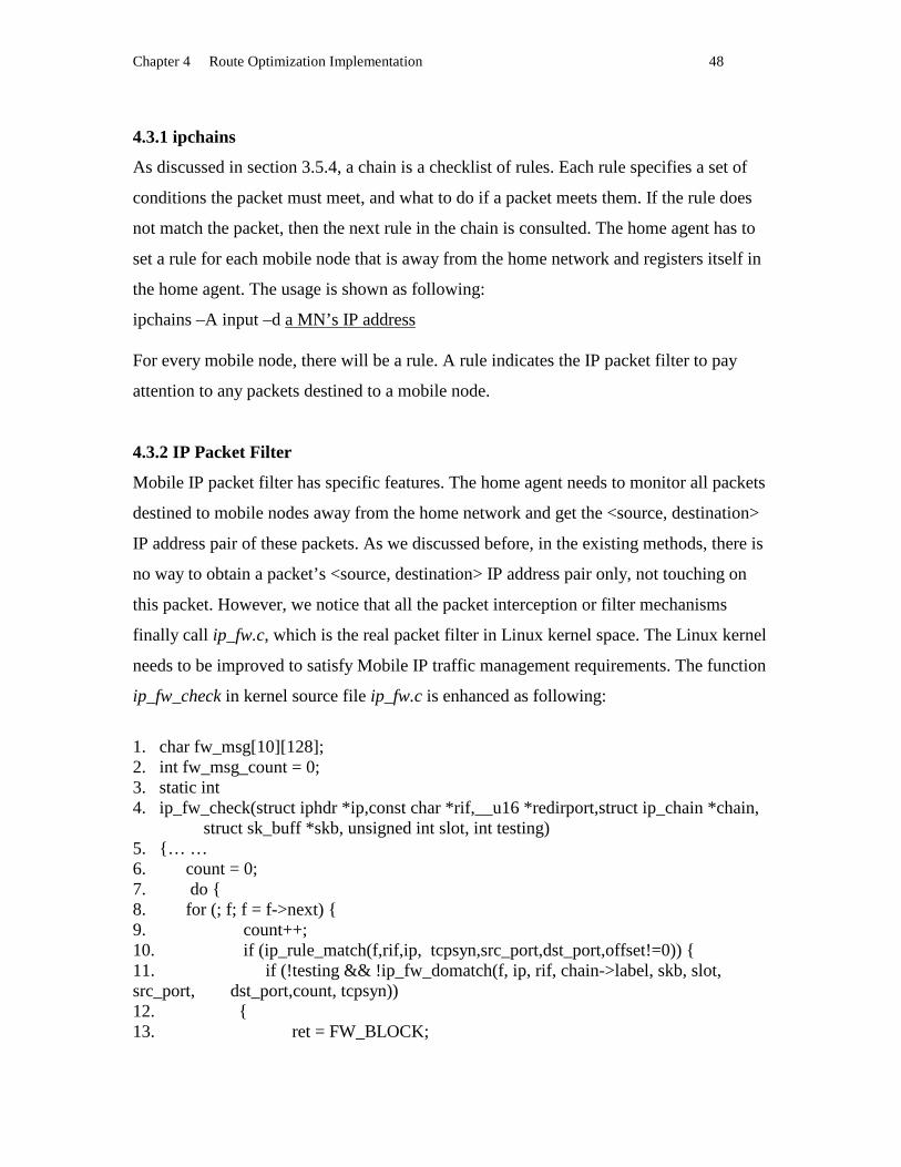
Chapter 4 Route Optimization Implementation 48
4.3.1 ipchains
As discussed in section 3.5.4, a chain is a checklist of rules. Each rule specifies a set of
conditions the packet must meet, and what to do if a packet meets them. If the rule does
not match the packet, then the next rule in the chain is consulted. The home agent has to
set a rule for each mobile node that is away from the home network and registers itself in
the home agent. The usage is shown as following:
ipchains –A input –d a MN’s IP address For every mobile node, there will be a rule. A rule indicates the IP packet filter to pay
attention to any packets destined to a mobile node.
4.3.2 IP Packet Filter
Mobile IP packet filter has specific features. The home agent needs to monitor all packets
destined to mobile nodes away from the home network and get the <source, destination>
IP address pair of these packets. As we discussed before, in the existing methods, there is
no way to obtain a packet’s <source, destination> IP address pair only, not touching on
this packet. However, we notice that all the packet interception or filter mechanisms
finally call ip_fw.c, which is the real packet filter in Linux kernel space. The Linux kernel
needs to be improved to satisfy Mobile IP traffic management requirements. The function
ip_fw_check in kernel source file ip_fw.c is enhanced as following:
1. char fw_msg[10][128]; 2. int fw_msg_count = 0; 3. static int 4. ip_fw_check(struct iphdr * ip,const char * rif,__u16 * redirport,struct ip_chain *chain, struct sk_buff *skb, unsigned int slot, int testing) 5. { … … 6. count = 0; 7. do { 8. for (; f; f = f->next) { 9. count++; 10. if (ip_rule_match(f,rif,ip, tcpsyn,src_port,dst_port,offset!=0)) { 11. if (!testing && !ip_fw_domatch(f, ip, rif, chain->label, skb, slot, src_port, dst_port,count, tcpsyn)) 12. { 13. ret = FW_BLOCK;

Chapter 4 Route Optimization Implementation 49
14. goto out; 15. } 16. /*write to fw_msg if it is not going to RETURN target* / 17. if(f->simplebranch != FW_SKIP+1) 18. { 19. ++fw_msg_count; 20. if(fw_msg_count>9) 21. fw_msg_count = 0; 22. switch(ip->protocol) 23. { 24. case IPPROTO_TCP: 25. printk("TCP package \n"); 26. sprintf(fw_msg[fw_msg_count],"TCP src: %u %u dst: %u
%u", ip->saddr, src_port, ip->daddr, dst_port); 27. break; 28. case IPPROTO_UDP: 29. printk("UDP package \n"); 30. sprintf(fw_msg[fw_msg_count],"UDP src: %u %u dst: %u
%u", ip->saddr, src_port, ip->daddr, des_port) 31. break; 32. case IPPROTO_ICMP: 33. printk("ICMP package \n"); 34. sprintf(fw_msg[fw_msg_count],"ICMP src: %u %u dst:
%u %u", ip->saddr, src_port, ip->daddr, dst_port);
35. break; 36. } 37. } 38. break; 39. } 40. } The main function of ip_fw.c is to consult a set of rules to determine whether to pass each
IP packet that is destined to the host or forwarded by the host.. Undesirable or potentially
unsafe packets can be blocked based on such things as the source and destination IP
addresses, protocol type, source or destination port, TCP flags, etc. In the ip_fw.c, the
function ip_fw_check( ) is responsible for checking if a packet matches a rule. If a packet
matches a rule, the ip_fw.c will check whether there is a target in this rule and call
different functions to take different actions according to the different targets. The
original ip_fw_check() does not have the code in line 17 --- line 35. We add the code into

Chapter 4 Route Optimization Implementation 50
ip_fw.c to meet the Route Optimization requirement. When ip_fw_check finds that a rule
is matched, line 17 checks if this rule’s target is return. If so, do not check the following
rules. This works for the BEBA algorithm. If a correspondent node does not support
Route Optimization, set an ipchains whose target is RETURN for this correspondent
node. Then, line 18---line 35 will be ignored. If not, get the protocol type of this packet.
According to different protocols, put the protocol type, source address, destination
address into fw_msg buffer. This buffer is declared by this implementation and is
managed by a FIFO strategy. After the improvement, ip_fw.c will filter the packets
according to the rules set by ipchains and put the packets’ source address, destination
address and protocol type in a kernel buffer. The next step is how to read a kernel buffer
(fw_msg buffer) from user space.
4.4 Communication Between User Space and Kernel Space
As discussed in Section 3.5.2 , to communicate between kernel process and user space,
there are two ways: creating a new system call or extending an existing system call. Since
our implementation only needs to get data from kernel space, an existing system call ioctl
() is extended to transfer the <source, destination> data in the kernel buffer to a user
space process.
The function inet_ioctl in the kernel source file af_inet.c is extended as following:
1. static int inet_ioctl(struct socket *sock, unsigned int cmd, unsigned long arg) 2. { 3. …… 4. switch(cmd) 5. { 6. …… 7. case SIOCFWMSG: /*send fw msg to the user space*/ 8. sprintf((char*) arg, ""); 9. for(c_msg_c = 0; c_msg_c<10; c_msg_c++) 10. { 11. if(strlen(fw_msg[c_msg_c])>0) 12. { 13. sprintf((char*) arg, fw_msg[c_msg_c]); 14. return (0); 15. } 16. } 17. case SIOCFWCLR: /*clear fw msg*/
Chapter 4 Route Optimization Implementation 51
18. sprintf(fw_msg[c_msg_c], ""); 19. return (0); 20. …… 21. } 22. ……. 23. }
The SIOCFWMSG, SIOCFWCLR are user extended commands in this implementation.
SIOCFWMSG is used to get the content of kernel buffer fw_msg[ ] . SIOCFWCLR is
used to clear the kernel buffer after every time the kernel buffer is read by
SIOCGWMSG. When a user space process needs to obtain the kernel buffer fw_msg[ ] , it
will open a raw socket and invoke system call ioctl() as following:
sd=socket(AF_INET, SOCK_RAW, IPPROTO_ICMP); ioctl(sd, SIOCFWMSG, (void*) msg); msg is a pointer to data transmitted from kernel. After the extension to the ioctl( ) system
call, the implementation can obtain data related to IP packet filter from the Linux kernel.
4.5 Set Tunnel
For every outgoing packet, the correspondent node has to check whether it is sent to a
mobile node of which the correspondent node has a binding cache entry. If there is an
entry for the destination mobile node, the packet needs to be tunneled by adding an outer
IP header and sent directly to the mobile node’s current location. This is the traffic
management part in this implementation.
In order to set a tunnel in the Linux kernel from a user space application, iproute2+tc
packets should be included in the implementation. Iproute2+tc is the Linux traffic
control engine, which allows access to a variety of new networking features in the Linux
2.2.* kernel, including setting up a tunnel and adding an entry into the route table from a
user space process. The following is a sample code to use the iproute2+tc to set a tunnel
in Linux:
1. #include <sys/socket.h> //for AF_INET 2. #include < linux/if_tunnel.h> //define struct ip_tunnel_parm 3. #include < net/if.h> //define struct ifreq

Chapter 4 Route Optimization Implementation 52
4. tunnel_t::tunnel_t() 5. { 6. …… …… 7. sock= socket(AF_INET, SOCK_DGRAM, 0); 8. } 9. void tunnel_t::do_add_ioctl(int cmd, const char *basedev, struct ip_tunnel_parm *p) 10 .{ 11. struct ifreq ifr; 12. strcpy(ifr.ifr_name, basedev); 13. ifr.ifr_ifru.ifru_data = (char*)p; 14. ioctl(sock, cmd, &ifr); 15. } 16. void tunnel_t::do_add_tunnel(ip32 local,ip32 remote,char* tunl_name) 17. { 18. struct ip_tunnel_parm p; 19. bzero(&p,sizeof(ip_tunnel_parm)); 20. p.iph.version = 4; 21. p.iph.ihl = 5; 22. #define IP_DF 0x4000 /* Flag: "Do not Fragment" * / 23. p.iph.frag_off = htons(IP_DF); 24. p.iph.protocol = IPPROTO_IPIP; 25. p.iph.daddr=remote; 26. p.iph.saddr=local; 27. strncpy(p.name,tunl_name,IFNAMSIZ); 28. do_add_ioctl(SIOCADDTUNNEL,"tunl0",&p); 29. cout<<"Add tunnel: "<<p.name<<" "<<endl; 30. } The implementation wraps the tunnel work in the tunnel_t class. In the constructor of
tunnel_t, tunnel_t creates an AF_INET socket for later use. Function do_add_ioctl( ) uses
the ioctl ( ) system call to send tunnel commands and related parameters to the Linux
kernel. Function do_add_tunnel ( ) accepts two IP addresses along with the tunnel device
name and assembles the struct ip_tunnel_parm, then calls do_add_ioctl() to accomplish
setting up the tunnel. Ip32 local is the local end IP address (the correspondent node’s IP
address). Ip32 remote is the remote end IP address (the mobile node’s care_of_address).
This tunnel will exist as a network device. Then, a new entry needs to be added into the
correspondent’s route table. This new entry specifies a route to a host via a specified
network device. In the correspondent node, the new entry specifies a route to a mobile
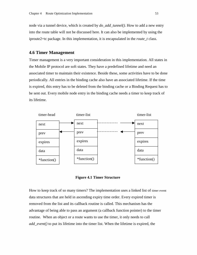
Chapter 4 Route Optimization Implementation 53
node via a tunnel device, which is created by do_add_tunnel(). How to add a new entry
into the route table will not be discussed here. It can also be implemented by using the
iproute2+tc package. In this implementation, it is encapsulated in the route_t class.
4.6 Timer Management
Timer management is a very important consideration in this implementation. All states in
the Mobile IP protocol are soft states. They have a predefined lifetime and need an
associated timer to maintain their existence. Beside these, some activities have to be done
periodically. All entries in the binding cache also have an associated lifetime. If the time
is expired, this entry has to be deleted from the binding cache or a Binding Request has to
be sent out. Every mobile node entry in the binding cache needs a timer to keep track of
its lifetime.
Figure 4.1 Timer Structure
How to keep track of so many timers? The implementation uses a linked list of timer event
data structures that are held in ascending expiry time order. Every expired timer is
removed from the list and its callback routine is called. This mechanism has the
advantage of being able to pass an argument (a callback function pointer) to the timer
routine. When an object or a route wants to use the timer, it only needs to call
add_event() to put its lifetime into the timer list. When the lifetime is expired, the
next prev expires data * function()
next prev expires data * function()
next prev expires data * function()
timer-head timer-list timer-list

Chapter 4 Route Optimization Implementation 54
associated callback function predefined in the object or function will be called. An object
or function also can cancel its predefined expire timer by calling rm_event(). Our timer
management mechanism is very similar to the Linux kernel timer structure. It is an
effective way to manage such a heavily timer dependent system. The timer management
list is illustrated in Figure 4.1.
4.7 Some Graphic Expression
In order to describe the design and implementation details of the home agent and the
correspondent node, we introduce some graphic representations used in the following
sections.
4.7.1 Class Relationship
“There are two relationships between two classes: client-server associations and peer-to-
peer associations. In the client-server association, the client is the object with the
reference; the server is the object with data or operation invoked by the client. Clients
must know about the servers to be able to invoke services from them. Servers should not
know about their clients. In the peer-to-peer association, there is recursion of operations
between the two classes. In client-server association, a server object has an association to
a client object in order to register itself with client. Once registered, the client object can
invoke methods on the server object.” [22]
In our thesis, we use a rectangle to indicate a class, a bidirectional arrow to express the
peer-to-peer association and a unidirectional arrow to express the client-server
Figure 4.2 Class Relationship
peer-to-peer association
Class Peer2 Class Peer1
client-server association
Class Class

Chapter 4 Route Optimization Implementation 55
association. In the unidirectional direction arrow situation, the class which is pointed to
by the arrow is the client, the class which is at the state of the arrow is the server. Figure
4.2 shows the graphic expressions.
4.7.2 Activity Diagrams
Activity diagrams represent the behavior of an operation as a set of action. In this thesis,
activity diagrams describe the activities inside a class. Figure 4.3 displays the graphic
representations of activities.
A filled circle indicates the start activity.
A filled circle with another outside circle indicates the end activity
A rectangle with circular corner indicates the general activity
A rectangle with one convex pentagon side indicates a sending activity
A rectangle with one concave pentagon side indicates a receiving activity
A diamond indicates a logical decision activity, it is labeled by multiple output transition
with different guard conditions.
Activities are linked by automatic transitions that are indicated by an arrow.
Figure 4.3 Activity Diagram Graphic Expression
4.8 Basic Mobile IP Architecture
The basic Mobile IP implementation is our starting point. Our Route Optimization makes
use of agent advertisement, agent solicitation, and registration components in basic
Mobile IP. The basic Mobile IP architecture and design style influences the Route
Optimization implementation. As part of the Route Optimization components, we will
summarize the design and implementation of basic Mobile IP. From the high level
Connect
receive activity start activity
end activity send activity
general activity
decision activity
transition

Chapter 4 Route Optimization Implementation 56
consideration, there are two major approaches to implement the three entities. One is
based on functions and procedures. The other is based on Object-Oriented principles.
Because of the well known advantage of OO, the basic mobile IP implementation choose
the second approach. To consider about the software efficiency, the home agent and the
foreign agent are implemented as one entity: agent. Any agent can act as a home agent
and a foreign agent at the same time. For the mobile nodes who belong to this home
network, the agent acts as the home agent. For the mobile nodes who belong to foreign
networks, the agent will act as the foreign agent. Dynamic binding in C++ facilitates this
design idea. Here, we introduce some useful classes created in the basic Mobile IP
implementation.
In the home agent:
• Class ag_reg_t , responsible for registration.
• Class ag_advert_t , responsible for agent’s advertisement or mobile node’s
solicitation .
• Class mobile_t, a super class to be inherited by local_mobile_t and remote_mobile_t
in order to combine the home agent and the foreign agent as the agent.
• Class local_mobile_t, responsible for home agent related functions.
• Class remote_mobile_t, responsible for foreign agent related functions.
• Class netmng_t, responsible for getting host’s system configuration information.
In the mobile node:
• Class cl_agent_t, a super class to be inherited by cl_home_t and cl_foreign_t
• Class cl_home_t, responsible for registration
• Class cl_foreign_t, responsible for solicitation or advertisement .
• Class cl_mng_t, responsible for getting host’s system configuration information
There is a binding cache in each home agent, which stores the location information for all
registered mobile nodes.
Chapter 4 Route Optimization Implementation 57
4.9 Correspondent Node
Mobile IP without Route Optimization does not need any support from a correspondent
node. That is one of the reasons why Mobile IP without Route Optimization is popular. In
a short term, deploying the Route Optimization support in every Internet host is almost
impossible. Especially for implementation existing in kernel, patching additional source
code and recompiling the kernel is a very tedious and error-prone process. Keeping this
reason in mind, for easy installation and usability, we choose to implement Route
Optimization functionality in the user space rather than embedded it in the kernel. It will
help the deployment of Route Optimization in the whole Internet. A user space
implementation especially facilitates the deployment of Route Optimization in
correspondent nodes. Certainly, in the future, with Mobile IP gaining popularity, we can
expect a large number of computers to be equipped with Route Optimization software.
No matter whether it is implemented in user space or kernel space, our software will
contribute to this migration period. Performance is a problem that may exist in the user
space implementation. However, the balance between simplicity and performance is one
of the considerations in this research. Good design and implementation will improve the
performance. In Chapter 5, we will get an insight of the performance of our user space
implementation. The implementation fulfills features of a correspondent node according
to the IETF Route Optimization draft. The functionality includes binding cache
management and traffic control. Binding cache management includes exchanging control
messages with home agents, authenticating control messages and maintaining binding
cache. Traffic control includes selecting traffic that the correspondent node has a binding
entry for, encapsulating those packets and sending them out directly. The software is
implemented in C++, following an object-oriented architecture. This section describes
implementation details of the correspondent node from several aspects: software
architecture, data structure, control flow.
4.9.1 Architecture
In Mobile IP with Route Optimization, a correspondent node fulfills the following
functions:
• Receiving Binding Update message from a home agent.

Chapter 4 Route Optimization Implementation 58
• Updating its binding cache and deleting the expired binding entry.
• Detecting traffic and tunneling packets that it has a binding entry for their
destinations.
The functions can be separated as five components: Binding Update message listener,
binding cache management, timer management, traffic controller, and security
management. Because our implementation is based on object-oriented principles, we
encapsulate the five components into seven classes: cpd_update_t, select_cb_t,
cpd_mobile_t, tunnel_t, route_t, timer_t, and sec_mng_t. The binding cache is a central
data structure in the correspondent node, which is implemented by a STL (C++ Standard
Template Library) associative container: Map.
select_cb_t class: responsible for listening to socket messages.
cpd_update_t class: responsible for managing the binding cache.
cpd_mobile_t class: responsible for managing the related mobile node and recording the
associated information.
tunnel_t class and route_t class: responsible for tunneling packets destined to mobile
nodes.
timer_t class: responsible for tracing all the timers in the system.
sec_mng_t class: responsible for authenticating a Binding Update message or a Binding
Acknowledgement message.
Figure 4.4 Class Relationship in a Correspondent Node
timer_t
cpd_update_t cpd_mobile_t tunnel_t
route_tsec_mng_t select_cb_t
IP Layer
Data Link Layer
User SpaceKernel Spacesocket
ioctl
ioctl
Chapter 4 Route Optimization Implementation 59
The relationships between these classes are illustrated in Figure 4.4:
Class cpd_mobile_t and class timer_t are a peer-to-peer association instead of a client-
server association because of the consideration of software reusability and extensibility.
Once a cpd_mobile_t object registers itself with the timer_t object, the timer_t object can
invoke methods on the cpd_mobile_t object. There is callback relationship between
cpd_mobile_t and timer_t. A timer_t object can accept different classes’ registration
requirements, then can trace different timers for different classes and objects as we
mentioned in Section 4.6. All time stamped objects can register themselves with the
timer_t object. When a timer is expired, the timer_t object will invoke the callback
function associated with the time stamped object. Every mobile node will associate with
a cpd_mobile_t object and has a lifetime. In the same way, cpd_update_t and select_cb_t
are a peer-to-peer association. Once a cpd_update_t object registers itself with the
select_cb_t object, the select_cb_t object can invoke methods on the cpd_update_t object.
Select_cb_t can listen on different sockets. If select_cb_t listens to a socket message for
cpd_update_t, it will call the read_sock() function in cpd_update_t. This feature enables
software extensibility and reusability.
Associated with these classes, there are the following objects in the correspondent node:
A cpd_update_t object: updater
A select_cb_t object: select_obj
A timer_t object: timer_obj
A sec_mng_t object: sec_obj
0 --- N cpd_mobile_t objects, 0 ---N tunnel_t objects, 0 --- N route_t objects.
N means the objects’ number, which is associated with the number of mobile nodes.
tunnel_t objects, and route_t objects have the same lifetime, decided by the
correspondent cpd_mobile_t objects’ lifetime.
4.9.2 Data Structure
The binding cache is implemented as a STL Map. Objects stored in a map consist of a
pair < key, value >. A value is associated with a key. Iterating through all the keys is
very efficient in STL maps. Our < key, value > pair in the binding cache map is <MN’s
ip address, cpd_mobile_t object representing this MN>, that is, every entry in the binding
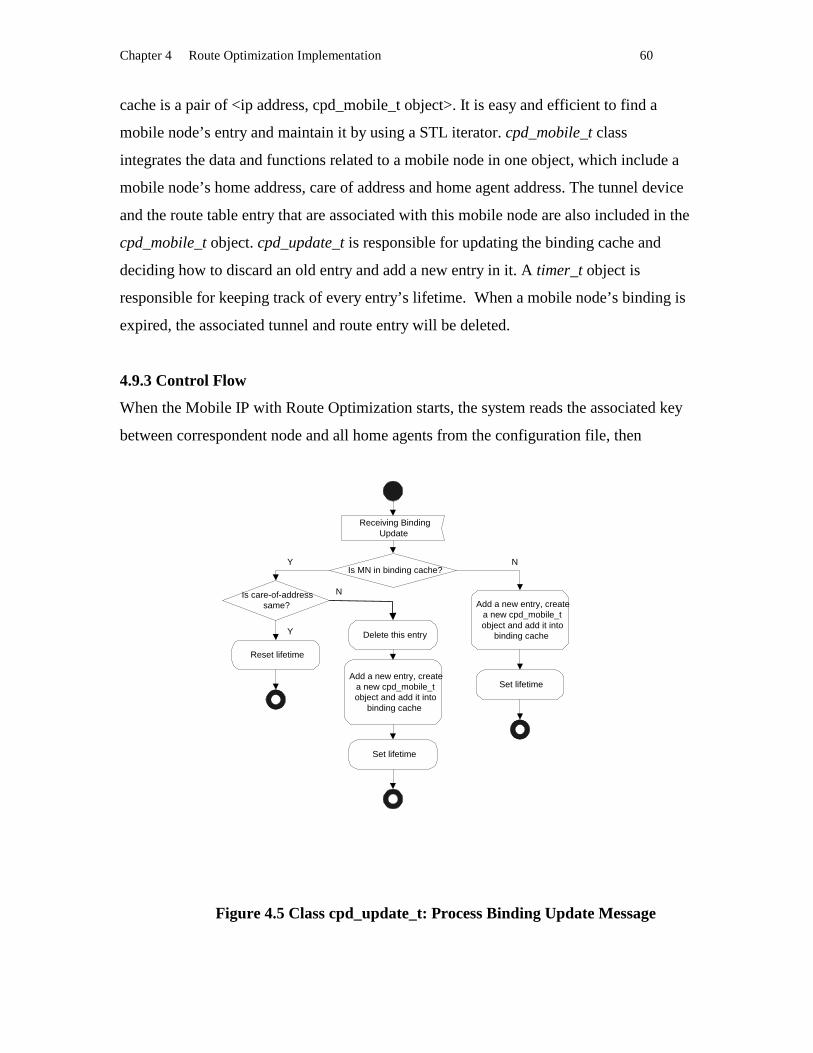
Chapter 4 Route Optimization Implementation 60
cache is a pair of <ip address, cpd_mobile_t object>. It is easy and efficient to find a
mobile node’s entry and maintain it by using a STL iterator. cpd_mobile_t class
integrates the data and functions related to a mobile node in one object, which include a
mobile node’s home address, care of address and home agent address. The tunnel device
and the route table entry that are associated with this mobile node are also included in the
cpd_mobile_t object. cpd_update_t is responsible for updating the binding cache and
deciding how to discard an old entry and add a new entry in it. A timer_t object is
responsible for keeping track of every entry’s lifetime. When a mobile node’s binding is
expired, the associated tunnel and route entry will be deleted.
4.9.3 Control Flow
When the Mobile IP with Route Optimization starts, the system reads the associated key
between correspondent node and all home agents from the configuration file, then
Figure 4.5 Class cpd_update_t: Process Binding Update Message
Receiving BindingUpdate
Is MN in binding cache?
Is care-of-addresssame?
Reset lifetime
Delete this entry
Add a new entry, createa new cpd_mobile_tobject and add it into
binding cache
Set lifetime
Add a new entry, createa new cpd_mobile_tobject and add it into
binding cache
Set lifetime
Y
Y
N
N

Chapter 4 Route Optimization Implementation 61
generates all the objects described in Section 4.9.1. The select_obj listens to all Binding
Update messages from different home agents. If there is a Binding Update message
received through the UDP socket, the select_object will invoke the cpd_update_t::
read_sock( ). The Updater object parses the received message and updates the binding
cache. If this is a new mobile node for the correspondent node, the updater object will
add a new entry into the binding cache. If the binding cache is full, the updater will
discard an old entry based on a FIFO strategy and insert the new entry. If the mobile node
already exists in the binding cache, the updater object will determine whether the care of
address remains the same as previous. If it is, just reset the mobile node’s lifetime. If not,
then delete the old entry and create a new entry for this mobile node. The procedure is
shown on Figure 4.5. (Process Binding Update Message). The other procedures are also
illustrated by Figure 4.6 – Figure 4.9.
Figure 4.7 Class timer_t: Timer Management
Receive tick fromoperating system
Goto next entryCallback to invokeexpire() in classcpd_mobile_t
Check the timer list, Isthere any timer
expired?
Y N

Chapter 4 Route Optimization Implementation 62
Figure 4.6 Class select_t: Receiving Binding Update Message
Figure 4.8 Class cpd_mobile_t: a mobile node expires
receiving messagefrom a socket
Listening Socket
Listening Socket
callback to invokethe associatedread_socket()
Receive timerexpired from time_t
Delete a route_t object
Delete a tunnel_tobject
Requiredcpd_update_tdelete itself

Chapter 4 Route Optimization Implementation 63
Figure 4.9 Class cpd_mobile_t: a mobile node is created
The cpd_update_t objectcreates a cpd_mobile-t
object
In the cpd_mobile_t, create atunnel_t object for the MN
In the cpd_mobile_t, create aroute_t object for the MN

Chapter 4 Route Optimization Implementation 64
4.10 Home Agent
This section describes the implementation details of the home agent for Route
Optimization.
4.10.1 Architecture
The Route Optimization adds two functional components into basic Mobile IP:
• traffic monitoring.
• Binding Update message management.
In order to monitor traffic by the packet filter in Linux kernel, ip_fw.c and af_inet.c
source code is extended. We also modify class ag_reg_t in basic Mobile IP to enable
traffic monitoring and create a new class ag_update_t to manage update message
sending. As soon as a mobile node registers with its home agent, the ag_reg_t class
notifies the Linux kernel to monitor all traffic destined to the mobile node by setting
ipchains for this mobile node. By improving the Linux kernel and extending the ioctl()
system call, ag_update_t object can obtain the address of a correspondent node, which
sends packets to a mobile node through the mobile node’s home agent. ag_update_t class
is responsible for implementing the BEBA algorithm, managing the correspondent node
cache, and receiving data from the traffic monitor. cpd_node_t class is responsible for
data and functions related to a correspondent node. The three classes ag_update_t,
cpd_node_t, and ag_reg_t collaborate with classes timer_t , sec_mng_t, and mobile_t to
achieve the Route Optimization in a home agent. The relationships between these classes
are illustrated by the class diagram in Figure 4.10:
Class cpd_node_t and class timer_t are in a peer-to-peer association instead of a client-
server association because of the consideration of software reusability and extensibility.
Once a cpd_node_t object registers itself with the timer_t object, the timer_t object can
invoke expire() methods on the cpd_node_t object. There is a callback relationship
between class cpd_node_t and class timer_t. This feature enables software extensible and
reusable.

Chapter 4 Route Optimization Implementation 65
Figure 4.10 Class Relationship in a Home Agent
Associated with these classes, there are the following objects in the home agent:
A cpd_update_t object: updater
A timer_t object: timer_obj
A sec_mng_t object: sec_obj
0 --- N cpd_node_t objects. The number N indicates the number of correspondent nodes
that are currently communicating with mobile nodes who belong to this home agent.
4.10.2 Data Structure
There are two caches in the home agent now. One is the binding cache and the other is
the correspondent node cache. The binding cache stores the mobile nodes’ binding
information, which is the same cache as in the basic Mobile IP. The correspondent node
cache is a new cache appearing in the Route Optimization implementation, which is
implemented as a link list. The correspondent node cache is created for the
implementation of the BEBA algorithm. ag_update_t collaborates with the correspondent
node cache and the binding cache to send Binding Update messages to a correspondent
node.
timer_t
Binding Cache ag_update_t cpd_node_t
ag_reg_t sec_mng_t
IP Layer
Data Link Layer
User SpaceKernel Space
ioctl,socket
basic Mobile IP
ipchains
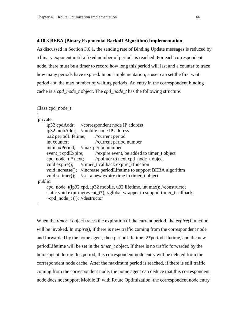
Chapter 4 Route Optimization Implementation 66
4.10.3 BEBA (Binary Exponenial Backoff Algor ithm) Implementation
As discussed in Section 3.6.1, the sending rate of Binding Update messages is reduced by
a binary exponent until a fixed number of periods is reached. For each correspondent
node, there must be a timer to record how long this period will last and a counter to trace
how many periods have expired. In our implementation, a user can set the first wait
period and the max number of waiting periods. An entry in the correspondent binding
cache is a cpd_node_t object. The cpd_node_t has the following structure:
Class cpd_node_t { private: ip32 cpdAddr; //correspondent node IP address ip32 mobAddr; //mobile node IP address u32 periodLifetime; //current period int counter; //current period number int maxPeriod; //max period number event_t cpdExpire; //expire event, be added to timer_t object cpd_node_t * next; //pointer to next cpd_node_t object void expire(); //timer_t callback expire() function void increase(); //increase periodLifetime to support BEBA algorithm void setimer(); //set a new expire time in timer_t object public: cpd_node_t(ip32 cpd, ip32 mobile, u32 lifetime, int max); //constructor static void expiring(event_t* ); //global wrapper to support timer_t callback. ~cpd_node_t ( ); //destructor } When the timer_t object traces the expiration of the current period, the expire() function
will be invoked. In expire(), if there is new traffic coming from the correspondent node
and forwarded by the home agent, then periodLifetime=2*periodLifetime, and the new
periodLifetime will be set in the timer_t object. If there is no traffic forwarded by the
home agent during this period, this correspondent node entry will be deleted from the
correspondent node cache. After the maximum period is reached, if there is still traffic
coming from the correspondent node, the home agent can deduce that this correspondent
node does not support Mobile IP with Route Optimization, the correspondent node entry
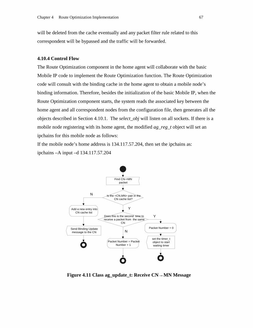
Chapter 4 Route Optimization Implementation 67
will be deleted from the cache eventually and any packet filter rule related to this
correspondent will be bypassed and the traffic will be forwarded.
4.10.4 Control Flow
The Route Optimization component in the home agent will collaborate with the basic
Mobile IP code to implement the Route Optimization function. The Route Optimization
code will consult with the binding cache in the home agent to obtain a mobile node’s
binding information. Therefore, besides the initialization of the basic Mobile IP, when the
Route Optimization component starts, the system reads the associated key between the
home agent and all correspondent nodes from the configuration file, then generates all the
objects described in Section 4.10.1. The select_obj will listen on all sockets. If there is a
mobile node registering with its home agent, the modified ag_reg_t object will set an
ipchains for this mobile node as follows:
If the mobile node’s home address is 134.117.57.204, then set the ipchains as:
ipchains –A input –d 134.117.57.204
Figure 4.11 Class ag_update_t: Receive CN→MN Message
Find CN->MNpacket
Is the <CN,MN> pair in theCN cache list?
Add a new entry intoCN cache list
Does this is the second time toreceive a packet from the same
CN
Packet Number = PacketNumber + 1
set the timer_tobject to startwaiting timer
Y
N
N
Y
Send BInding Updatemessage to the CN
Packet Number = 0

Chapter 4 Route Optimization Implementation 68
This sets a rule in the Linux kernel to indicate that any packet destined to the mobile node
134.117.57.204 will be noticed and the source address and destination address of this
packet will be extracted and sent to a buffer. Another object, the ag_update_t object will
invoke the extended system call ioctl() to get the <src,dest> pair. Then ag_update_t
Figure 4.12 Class ag_update_t: Send Binding Update Message
object implements the BEBA algorithm to decide if it is necessary to send a Binding
Update message to the correspondent node. If a Binding Update message is to be sent
out, the ag_update_t object will inquire the binding cache to get the care of address and
lifetime of the mobile node, then assemble the Binding Update message and send it to the
correspondent node. A home agent also listens on all Binding Requests from
correspondent nodes and replies to them with a Binding Update message. These
procedures are illustrated by Figure 4.11 to Figure 4.16.
Last waiting time forBEBA expires
Intercept one or more CN’s packets during the waiting
period?
Delete the entry incorrespondent node’s
cache
Delete this entry
Does the total BEBA waiitingtime expires?
Set the new wating timeto the timer_t object.
new waiting time =2*(previous waiting time)
Disable thetraffic monitor for
this CN in kernel
Y
N
N
Y
Send BInding Updatemessage to the CN
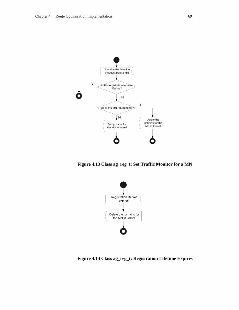
Chapter 4 Route Optimization Implementation 69
Figure 4.13 Class ag_reg_t: Set Traffic Monitor for a MN
Figure 4.14 Class ag_reg_t: Registration L ifetime Expires
Receive RegistrationRequest from a MN
Is this registration for resetlifetime?
Delete theipchains for the
MN in kernel
N
Y
Y
Set ipchains forthe MN in kernel
Does the MN return home?
N
Registration lifetimeexpires
Delete the ipchains forthe MN in kernel

Chapter 4 Route Optimization Implementation 70
Figure 4.15 ip_fw.c: Enhancement to Support HA’s Traffic Monitor
Figure 4.16 ag_update_t: Obtain Traffic Monitor Message from Kernel
Receive incomingpackets
Is one of the rules set byipchains for MNs is fit to
the packet
N
Y
N
Obtain <src, des> ,protocol type from thepacket and put it in a
kernel buffer
Get the <src, des>message from Kernel by
enhanced ioctl()
Is there a data in thekernel buffer?N
Y

Chapter 5 Experiment and Evaluation 71
Chapter 5
Exper iment and Evaluation The previous chapters introduce the Mobile IP with Route Optimization approach and its
implementation to support the mobility in an IP-based backbone network. Although the
architecture possesses the features to support the mobility and eliminates the triangle
routing existing in basic Mobile IP, the performance improvement will depend on the
relative positions of communication peers and the bandwidth of links. In this chapter, two
aspects are tested. One is to demonstrate that this implementation accomplished the
functions defined in the draft of Mobile IP with Route Optimization. The other is to
evaluate the performance. The performance will be evaluated in different cases. Through
this chapter’s investigation, the benefits obtained from Route Optimization will be
demonstrated.
5.1 Testbed
The experimental system configuration (Figure 5.1) consists of three subnets:
134.117.57.0, 134.117.66.0, and 134.117.67.0. Subnet 134.117.57.0 is the mobile node’s
home network with a 10 Mbps LAN (compliant with IEEE 802.3 specification). Subnet
134.117.66.0 acts as the mobile node’s foreign network with a 10 Mbps LAN and a 2
Mbps WaveLAN (2.4 GHz WaveLAN compliant with IEEE 802.11 specification for
wireless LANs). There are two correspondent nodes. One exists in the 134.117.66.0
subnet. The other resides in the 134.117.67.0 subnet. A mobile node will move from the
134.117.57.0 subnet to the 134.117.66.0 subnet. The mobile node is a Dell Inspiron 3500
laptop. The domain name of the mobile node is WMC-057204. Its home IP address is
134.117.57.204. The domain name of the home agent is Kunz3-57. Its IP address is
134.117.57.101. The domain name of the foreign agent is WMC-066021. Its IP address is
134.117.66.21. The domain name of the correspondent node is WMC-067140. Its IP
address is 134.117.67.104. The link between the mobile node and foreign network is the
wireless WaveLAN. The other three entities (the home agent, the foreign agent and the
correspondent node ) are stationary hosts connected to10 Mbps LANs. The
communication bottleneck in this experimental system is the wireless WaveLAN.
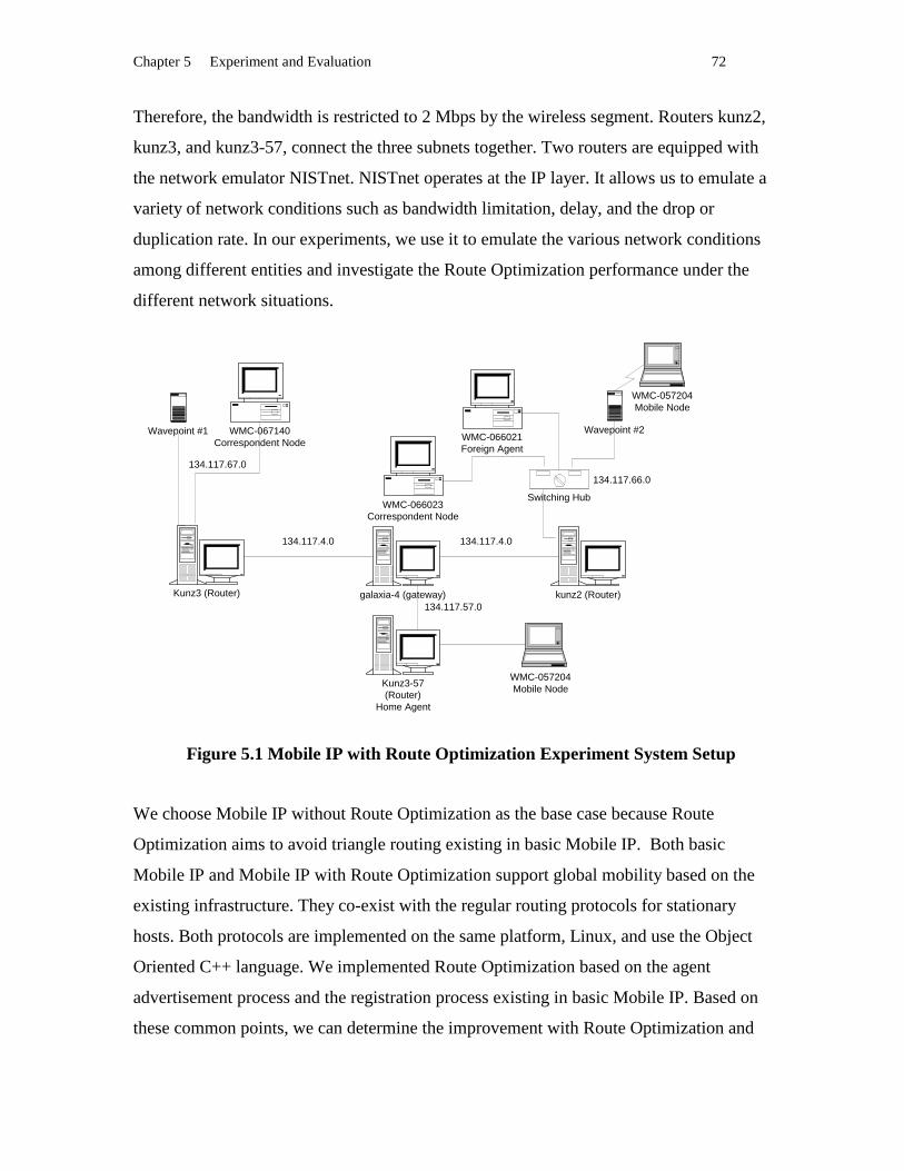
Chapter 5 Experiment and Evaluation 72
Therefore, the bandwidth is restricted to 2 Mbps by the wireless segment. Routers kunz2,
kunz3, and kunz3-57, connect the three subnets together. Two routers are equipped with
the network emulator NISTnet. NISTnet operates at the IP layer. It allows us to emulate a
variety of network conditions such as bandwidth limitation, delay, and the drop or
duplication rate. In our experiments, we use it to emulate the various network conditions
among different entities and investigate the Route Optimization performance under the
different network situations.
Figure 5.1 Mobile IP with Route Optimization Exper iment System Setup
We choose Mobile IP without Route Optimization as the base case because Route
Optimization aims to avoid triangle routing existing in basic Mobile IP. Both basic
Mobile IP and Mobile IP with Route Optimization support global mobility based on the
existing infrastructure. They co-exist with the regular routing protocols for stationary
hosts. Both protocols are implemented on the same platform, Linux, and use the Object
Oriented C++ language. We implemented Route Optimization based on the agent
advertisement process and the registration process existing in basic Mobile IP. Based on
these common points, we can determine the improvement with Route Optimization and
WMC-057204Mobile Node
WMC-057204Mobile Node
Kunz3 (Router) kunz2 (Router)
WMC-067140Correspondent Node WMC-066021
Foreign Agent
Kunz3-57(Router)
Home Agent
Switching Hub
Wavepoint #1 Wavepoint #2
WMC-066023Correspondent Node
134.117.4.0
134.117.67.0
134.117.66.0
galaxia-4 (gateway)
134.117.4.0
134.117.57.0

Chapter 5 Experiment and Evaluation 73
demonstrate that Mobile IP with Route Optimization is a better choice than basic Mobile
IP in terms of performance. We also use plain IP as a comparison purpose to quantify the
performance degradation because of the overhead incurred by data tunneling and Binding
Update message processing.
5.2 Functionality
As we discussed in the previous chapters, one of the main differences between Mobile IP
with Route Optimization and basic Mobile IP is that correspondent nodes will cache the
location information for mobile nodes. One of the main components added by Route
Optimization is to monitor the IP packets destined to mobile nodes and to send a Binding
Update message to the correspondent node by the home agent. After receiving the
Binding Update message, the correspondent node will cache the mobile node’s current
location information and set the associated tunnel. The routes taken by packets after the
correspondent nodes have the binding cache are shorter than that taken by packets before
route optimality. In order to demonstrate that our implementation achieves the goals, we
use the traceroute utility to trace the route before Route Optimization and that after Route
Optimization.
5.2.1 Traceroute
The traceroute utility traces the route of an IP packet by launching a UDP probe packet
with small ttl (time to live). The simplest usage is:
traceroute destination IP address
From the output of traceroute, we can observe the intermediate routers that the UDP
packet travels through.
5.2.2 Binding Update Exper iment
According to the draft of Route Optimization in Mobile IP, when a correspondent node
sends a packet to a mobile node for the first time, it does not know the current location of
the mobile node. The first packet will travel to the home agent of the mobile node, and
then it is delivered by the home agent to the foreign agent. After that, it is forwarded to
the mobile node by the foreign agent. This first packet will follow a route that every

Chapter 5 Experiment and Evaluation 74
packet in basic Mobile IP takes. However, when the first packet travels through the home
agent, the Route Optimization component in the home agent should capture it and send a
Binding Update message to the correspondent node. Following packets sent by the
correspondent node will travel directly to the mobile node instead of going through the
home agent triangle. In order to demonstrate these effects, we design three experiments:
1. Experiment one: traceroute on basic Mobile IP
a) Running basic Mobile IP on the testbed.
b) Issuing command “ traceroute 134.117.57.204” on WMC-067140 ( the
correspondent node).
The traceroute utility shows the route of the packet as follows:
kunz3 (router) �������! #"$� -4 (gateway) %'&'(')+* -57 (router and the home agent)
,�-/.�-!0#1�- -4 (gateway) 2'3'4'57698;:=</3'>@?A:CB DFEHG -066021 (the foreign agent) I/J/KMLNI'I/O'LQP'O'L RMS/K9T;U�VMWXZY/[M\�]�W_^MY'`'W!a=L
2. Experiment two: traceroute the very first packet on Mobile IP with Route Optimization
a) Running Mobile IP with Route Optimization on the testbed
b) Issuing command “ traceroute 134.117.57.204” on WMC-067140 ( the
correspondent node).
The traceroute utility shows the route of the packet as follows :
kunz3 (router) b�c�d�c!e#f$c -4 (gateway) g'h'i'j+k -57 (router and the home agent)
l�m/n�m!o#p�m -4 (gateway) q'r's't7u9v;w=x/r'y@zAwC{ |F}H~ -066021 (the foreign agent) �/�/�M�N�'�/�'�Q�'�'� �M�/�9�����M�_�H�/�M���$��M�'�'�!���
3. Experiment three: traceroute the second packet on Mobile IP with Route Optimization
a) Running Mobile IP with Route Optimization on the testbed
b) Issuing command “ping –c 1 134.117.57.204” on WMC-067140 (the correspondent
node).
c) Issuing command “ traceroute 134.117.57.204” on WMC-067140 (the
correspondent node).
The traceroute utility shows the route of the packet as follows :
kunz3 (router) �������!�#�$� -4 (gateway) �'�'�'�7�9�; =¡/�'¢�£! C¤ ¥§¦Z¨ -066021 (the foreign
agent) ©/ª/«M¬N©'©/'¬Q®''¬ ¯M°/«9±�²�³M´_µH¶/·M¸�¹$´ºM¶'»'´!¼�¬

Chapter 5 Experiment and Evaluation 75
From the above three experiments, the observation shows that the first packet in Mobile
IP with Route Optimization follows the same route taken by all the packets in basic
Mobile IP. However, the second packet sent by traceroute travels a shorter route to the
mobile node after the first packet is sent to the mobile node in the third experiment.
Between the first packet and the second packet, our Route Optimization component
works correctly.
5.3 Per formance
5.3.1 Evaluation Cr iter ia
Usually, there are two criteria to measure the performance of a network and its protocols:
throughput and latency. The throughput is the amount of data transferred by a network in
a time unit. Generally, it is expressed as Mbps, a million bits per seconds. Latency is the
time taken by a packet from a host to another host. It consists of propagation delay and
processing delay. Ideally, we hope to place our implementation in the actual network and
vary the location and distance of the three entities to evaluate the performance. However,
there are some difficulties to deploy our entities in different locations of the Internet. We
exploited the emulation environment in our Lab. Because the actually physical distance is
short and NISTnet is unable to emulate the latency effectively, we do not evaluate
latency. We use the throughput as the performance criteria in our evaluation.
5.3.2 Benchmark
TCP is a representative transport layer protocol used in many applications. Mobile IP
with Route Optimization supports the mobility at the IP layer and is transparent to the
transport layer. Either TCP or UDP can be used as the transport layer protocol in our
experiments. We use TCP as the upper layer protocol because it is more sensitive to
packet loss and delay than UDP. The throughput of an application exploiting TCP is
more representative than that of UDP. Besides, TCP is used widely because it provides
reliability and guarantees delivery. TCP performance is widely used for the evaluation of
the underlying IP layer [23]. Based on the choice of TCP, we select FTP as the
benchmark because it provides the throughput measurement. Another reason we select
FTP as the benchmark is that FTP is used in several similar experiments to evaluate
mobility performance [23]. As for the transferred file size, we also took hints from these

Chapter 5 Experiment and Evaluation 76
experiments. A medium file size is chosen in order to reduce the TCP’s start overhead.
We use FTP to download a 20 Mb file from the correspondent node to the mobile node.
The performance is measured as TCP throughput inside FTP.
5.3.3 Scenar ios Design
To demonstrate and quantify the enhancement in Route Optimization, we consider a base
scenario of triangle routing. Longer routes mean increased variance on the way, such as
more constraints on available bandwidth, increased drop rates, longer physical distances,
more processing time and the need to pass through more intermediate routers. In a
nutshell, longer routes typically mean lower bandwidth, higher drop rate, longer latency
and more unpredictable factors. At the same time, for the network itself, longer routes
result in bandwidth waste and other resource waste such as router’s processing time and
intermediate buffer consumption. The triangle routing overhead may be significant in
some cases, for example when a mobile node moves to a position which is very near to a
correspondent node, and is far away from the home network. An extreme situation is that
the mobile node moves to the same network as the correspondent node and the home
agent is far away. We explore this case in our experiment. To simulate the influence of
longer routes, we design two clusters of experiments. The two clusters separate the
effects of a longer distance into two factors. One cluster focuses on the bandwidth
degradation resulting from the increased distance. The other cluster concentrates on the
increase of the drop rate while the distance is longer. We will investigate how the
changes of available bandwidths between the three paths (from the correspondent node to
the home agent, from the correspondent node to the foreign agent, and from the home
agent to the foreign agent) will impact the performance of Mobile IP with Route
Optimization. We also simulate the relationship of the locations of the three entities by
their drop rates and evaluate the performance under the associated network situation. The
performance of running a TCP application above the IP layer with Route Optimization as
the mobility supporter is compared with that of Mobile IP without Route Optimization.
To quantify the overhead incurred by Route Optimization, we also use FTP to download
the same file without any mobility support. In the same network situation, the two
different underlying mobility protocols will generate different results. The benefits of
Route Optimization will be demonstrated in these different scenarios.

Chapter 5 Experiment and Evaluation 77
5.3.4 Exper imental Data Process
Our testbed is not a dedicated network. It is part of the sub network belonging to the
Department of System and Computer Engineering. The throughput will fluctuate with
various factors such as a unpredictable data flow sent by other network users or different
test time periods. In order to obtain more reliable data, we take several measures. First,
we did all the experiments at the same time periods –from 10 pm to 6am. In this time
period, relatively few interference appears. Second, every single test was repeated 20
times to calculate the average and the confidence interval by the follow formulas:
Suppose we have N=20 values v(i) measured,
average A = (sum of v(i))/N
standard deviation S2= (sum of (v(i) - average)2)/N
95% confidence interval for 20 samples = A +/- 2.09*sqrt(S2/N)
Here, we introduce the confidence interval to evaluate our test results because of the fact
that (average value of A) > (average value of B) does not means series A(i)>series B(i). It
could well be that some of the B(i) are bigger than some of the A(i), and the fact that A
and B are different is just a random occurrance. However, if the 95% confidence interval
for A is [a_low, a_high] and the 95% confidence interval for B is [b_low, b_high], then:
if A > B and b_high < a_low (i.e., the confidence intervals do not overlap), there is strong
statistical evidence that A indeed is bigger than B (or in more technical terms: A > B is
statistically significant at a 95% confidence level). There are actually more refined test in
case the confidence intervals overlap, such as a t-test. Should the confidence intervals
overlap AND the means are in the overlap region, then there is no statistical support for
A really being bigger than B.
5.3.5 Typical Case
The scenario that the mobile node moves into the same subnet as the correspondent node
is the typical case we will investigate. To explore the performance under the impact of
the network link between the foreign network and the home network, two groups of
experiments are done in terms of the decrement of bandwidth and the increment of the
drop rate between the foreign agent and the home agent. Table 5.1 and Table 5.2 show
the throughput for the various bandwidths and drop rates. Conf. Int. is the abbreviation of
confidence interval.

Chapter 5 Experiment and Evaluation 78
Table 5.1 MN and CN in the Same Sunnet, Varying HA ½¿¾ÁÀ�Â'ÃÅÄ�ÆÈÇ�ÄÅÉËÊ
HA ÌÎÍ Max Bandwidth
Plain IP Throughput (Mbps)
Basic M-IP Throughput (Mbps)
Route Optimization Throughput (Mbps)
Average 1.561 1.341 1.543
2 Mbps Conf. Int. [1.548, 1.574] [1.165, 1.517] [1.518, 1.568]
Average 1.552 1.264 1.538
1.5 Mbps Conf. Int. [1.551, 1.553] [1.119, 1.409] [1.517,1.559]
Average 1.556 0.944 1.527
1 Mbps Conf. Int. [1.555, 1.557] [0.907, 0.981] [1.506, 1.547]
Average 1.553 0.469 1.529
0.5 Mbps Conf. Int. [1.552, 1.554] [0.438, 0.5] [1.517, 1.541]
Average 1.557 0.087 1.532
0.1 Mbps Conf. Int. [1.556, 1.558] [0.075, 0.099] [1.507, 1.55]
Table 5.2 MN and CN in the Same Subnet, Varying HA Ï¿ÐÁÑFÒ�Ó'ÔÖÕF×'ØCÙ HA ÚÎÛ Drop Rate
Plain IP Throughput (Mbps)
Basic M-IP Throughput (Mbps)
Route Optimization Throughput (Mbps)
Average 1.558 1.39 1.531
0% Conf. Int. [1.557, 1.559] [1.398, 1.391] [1.53, 1.532]
Average 1.561 1.214 1.517
0.5% Conf. Int. [1.56, 1.562] [1.213, 1.215] [1.516, 1.518]
Average 1.556 1.184 1.53
1.5% Conf. Int. [1.555, 1.557] [1.183, 1.185] [1.529, 1.531]
Average 1.558 1.139 1.537
2.5% Conf. Int. [1.557, 1.559] [1.138, 1.14] [1.536, 1.538]
Average 1.56 1.035 1.534
5.0% Conf. Int. [1.559, 1.561] [1.034, 1.036] [1.533, 1.535]
We choose 2 Mbps as the maximum bandwidth because of the constraints of WaveLAN.
The minimum bandwidth of 0.1 Mbps is a restriction that comes from the emulator.
NISTnet utilizes buffers to achieve the simulation of low bandwidth. If the simulating

Chapter 5 Experiment and Evaluation 79
bandwidth is too low, the buffer will overflow and cannot generate normal simulation
result. The general maximum drop rate is 5% in the Internet [25]. Therefore, we keep it
as the maximum drop rate in our experiments.
We can make several observations from the tables. First, as bandwidth becomes
narrower from 2 Mbps to 0.1 Mbps, the throughput of Route Optimization or plain IP
keeps unchanged. In contrast, the throughput of basic Mobile IP degrades dramatically
along with the available bandwidth between the foreign agent and the home agent.
Especially, when the bandwidth decreases to 0.1 Mbps, Route Optimization has nearly 17
times the throughput as compared to basic Mobile IP. However, this is only a 1.6% loss
compared to plain IP. Considering the impact of the drop rate, the throughput of basic
Mobile IP drops from 1.39 Mbps to 1.035 Mbps when it increases from 0% to 5%. When
the drop rate reaches 5%, there is about 48% efficiency gains in Route Optimization as
compared to basic Mobile IP, and only 1.7% loss in Route Optimization compared to
plain IP. It is clear that in the extreme case the advantage of Route Optimization is
obvious.
Second, the test results confirm to our expectations. For plain IP, the FTP throughput
varies from 1.558 Mbps to 1.561 Mbps while the maximum bandwidth of the wireless
segment is 2 Mbps. Every 1480 byte payload has 20 bytes TCP header, 20 bytes IP
header and 42 bytes Ethernet header [26]. TCP payload data rates are thus:
1480 / (20+20+42+1480) = 94.75%
Ideally, over 2M WaveLAN, TCP throughput can reach 2 Mbps * 94.75% = 1.89Mbps.
However, FTP may add extra processing overhead and the varying error rate of the
wireless links may decrease the throughput further. More detail analysis done in M.I.T
laboratory shows an even lower maximum throughput of 1.7 Mbps on a 2M wireless
links [27]. Therefore, in our experimental environment, the 1.56 Mbps TCP throughput is
a reasonable value.
Third, with any bandwidth and at any drop rate, Route Optimization has only 1.4% to
1.7% efficiency loss compared to plain IP. The loss is caused by the tunneling overhead.
Every 1480 bytes data involves 20 bytes IP-in-IP header. The logical efficiency loss is
about 20 / 1480 ÜÞÝ/ß à'áâß/ãNäæå�ç#èMéAêCëíì�î�ï'ç�é_ä@ïðï/ñ'êòä�é�çËäóê=é�çËñMîôä@ç�ß

Chapter 5 Experiment and Evaluation 80
Fourth, there are some overlaps between the confidence interval of throughput of plain IP
and that of Mobile IP with Route Optimization when the HA õÎöø÷Mù!úMû/üþý$û/ÿ��9ù�������â÷� �and 1.5 Mbps. Statistically, we can not say the throughput of plain IP is greater than that
of Mobile IP with Route Optimization. Theoretically, there is tunnel overhead in Mobile
IP with Route Optimization. We can observe from the overlap that sometimes the tunnel
overhead is insignificant when the fluctuation in the network is big. However, on most
case, there is no overlap between those confidence intervals.
5.3.6 Bandwidth and Performance
Three links CN ��������� ��������� ����� �������! #"$��% &�'(% )�"$�*�+ # �,.- ���"(/0 ���*213&�4performance versus bandwidth. The individual experiments differ in terms of the specific
degrading link bandwidth among the three links. Other factors such as drop rate and
delay are minimized. The performance of Route Optimization under the variation of
bandwidth are investigated in each scenario. Basic Mobile IP and plain IP are also
employed for comparison purpose.
5.3.6.1 CN 576�8�9;:<5�6 =?>A@CBD9;EGFH8�9;:JIKB�:;LNMGO�P)Q�R)8�:;BD9 QS;BDTVU;W�LN8�9;P)X�U;Y�W(Z
As Figure 5.3 shows, the maximum bandwidth between the correspondent node and the
mobile node is constant 2 Mbps. The available bandwidth between the correspondent
node and the home agent, and between the home agent and the mobile node degrade from
2 M to 0.1 M at the same time. Table 5.3 shows the throughput of Route Optimization,
basic Mobile IP and plain IP under varying bandwidths between CN []\_^�` aHA bdc�e�fHgih jkeilmh�n2e�oDpqn�r s�t�u�u�v!s�w oDt�n2oDgihGg�jyx)gih jNo�z�s�h xis#o(h�n{s�vkw t)|De There are some similarity between this scenario and the scenario in Section 5.3.5. In the
experiment in Section 5.3.5, the bandwidth between the home agent and the foreign
agent degrade at the same time. It has the same logical impact as the bandwidth between
the correspondent node and the home agent, and between the home agent and the mobile
node degrading simultaneously. However, in Section 5.3.5, the correspondent node is
WMC-066023 ( Figure 5.1) and the mobile node resides physically at the same sub
network 134.117.66.0 with the correspondent node. In this scenario, the correspondent
node is WMC-067140 ( Figure 5.1), which resides at sub network 134.117.67.0. The

Chapter 5 Experiment and Evaluation 81
mobile node moves to sub network 134.117.66.0. Physically the mobile node and the
correspondent node are not in the same network. We separate the two experiments
because of the following reason. When the mobile node and the correspondent node are
physically in the same network, the mobile node will use the same links between foreign
network and home network to communicate. In our testbed, the segments of LAN
between Kunz3 and galaxia-4, between galaxia-4 and kunz3-57, are doubly used. Link
usage is double, while actual throughput remains the same. If link usage was more than
half the link capacity, this effect may even reduce the actual data throughput [23].
The data in Table 5.3 demonstrates three observations:
First, when the links between CN }]~ and HA �d�����)���!�)���#������� �����������2�(�0����� �����the bandwidth between CN ���_�����)�i� �N�2�����2�i��� ���)�k�N���)�D��� �������¡ ¢�i£��2�#¤¦¥��2�$§��(¨¡���2���i�G��� ©plain IP keeps unaffected. Second, the efficiency of Mobile IP with Route Optimization
as compared to basic Mobile IP is shown to be more and more significant (from 5.6% to
17 times) when the bandwidths between CN ª�«�¬� ®�ª]« ¯�°A± ²)³)´iµ�²� ¬�¶k¶�´i·�²�¶3¬� ®narrower (from 2 Mbps to 0.1 Mbps). Third, even when the maximum bandwidths
between CN ¸�¹�ºi¸�¹ »d¼�º�½�¾ ¿ÀÁ¼ »�¼�½�Â!Ã�ÄDÅ Ã#Æ�½�Ç0Ã�È»�É�Ê Æ�ºiÄDÅ Ã�Ä�Å�Â�ËiÌ ghput of
Route Optimization has 5.6% gain compared to basic Mobile IP because of the longer
physical distance involved by the route of basic Mobile IP and one more forwarding in
the mobile node’s home network. In our experiment environment, the actual distances
involved are pretty short, only about 200 m between CN Í]Î_Ï�Ð Ñ�Í�Î ÒdÓ�ÔiÕ×Ö#ØiÏ�Ðdeduce that if the distance increases, the efficiency gains will increase more. The
quantitative relationship between the efficiency gain and the physical distance have to be
explored by future internetworking experiments.

Chapter 5 Experiment and Evaluation 82
Figure 5.3 CN Ù�Ú_Û�Ü;Ý<Ù�Ú Þ?ßáàHÛ�Ü;ÝJâKã�Ý;äNåGæ�ç)è�é)Û�Ý;ãDÜ è
Table 5.3 CN ê7ë�ì�í;î<ê�ë ï?ðAñCòDí;óGôHì�í;îJõKò�î;öN÷Gø�ù)ú�û)ì�î;òDí úü;òDýVþ;ÿ�öNì�í;ù���þ���ÿ��
CN HA, HA ��� Max Bandwidth
Plain IP Throughput (Mbps)
Basic M-IP Throughput (Mbps)
Route Optimization Throughput (Mbps)
Average 1.547 1.442 1.524
2 Mbps Conf. Int. [1.546, 1.548] [1.418, 1.466] [1.515, 1.533]
Average 1.543 1.341 1.518
1.5 Mbps Conf. Int. [1.542, 1.544] [1.32, 1.362] [1.507, 1.529]
Average 1.537 0.907 1.516
1 Mbps Conf. Int. [1.536, 1.538] [0.863, 0.937] [1.507, 1.525]
Average 1.54 0.47 1.506
0.5 Mbps Conf. Int. [1.539, 1.541] [0.462, 0.478] [1.492, 1.52]
Average 1.542 0.084 1.512
0.1 Mbps Conf. Int. [1.541, 1.543] [0.077, 0.091] [1.498, 1.526]
CN MN
HA
CN MN
HA
CN MN
HA
CN MN
HA
CN MN
HA
2M 2M
2M
1.5M
2M
0.5M
1.5M
0.5M
2M
2M 2M
1M 1M
0.1M 0.1M

Chapter 5 Experiment and Evaluation 83
5.3.6.2 CN � �������������������������
Figure 5.4 CN ������ �!#"%$'&�"�(*)�+�,�-�.� �"�&�!�-
Table 5.4 Only CN /�0�1�2�3�4�576�3�8%9:2;8#<>=�?A@�B�CD6�8#2;3�B CN E�F Max Bandwidth
Plain IP Throughput (Mbps)
Basic M-IP Throughput (Mbps)
Route Optimization Throughput (Mbps)
Average 1.547 1.442 1.524
2 Mbps Conf. Int. [1.546, 1.548] [1.418, 1.466] [1.515, 1.533]
Average 1.543 1.342 1.512
1.5 Mbps Conf. Int. 1.542, 1.544] [1.321, 1.363] [1.501, 1.523]
Average 1.533 0.907 1.514
1 Mbps Conf. Int. [1.532, 1.534] [0.877,0.937] [1.503, 1.525]
Average 1.53 0.47 1.511
0.5 Mbps Conf. Int. [1.529,1.531] [0.461,0.479] [1.503, 1.519]
Average 1.536 0.091 1.518
0.1 Mbps Conf. Int. [1.535, 1.537] [0.088,0.094] [1.514, 1.522]
CN MN
HA
CN MN
HA
CN MN
HA
CN MN
HA
CN MN
HA
2M 2M
2M
2M
2M
0.5M
1.5M
2M
2M
2M 2M
2M 1M
2M 0.1M

Chapter 5 Experiment and Evaluation 84
Section 5.3.6.1 shows the efficiency gains of Route Optimization while the links between
CN G�H�IKJ#LMGAH N�O�L�P�QSRTI�L�PVUTWYX[Z#\�]^IKJ#P�_DZ#UT\Y`baDG[_Dc[PKd#PKRfe�WYJgI�hK];Z#I�\iUTWY]�Z#IK]^W�_DJ#UTe�WY]jW;UkXl_DRTPlikely that only one of the links degrades instead of two links. Here, we explore the
performance of Route Optimization if only the maximum bandwidth between CN mAndrops while the bandwidths between HA o�p qsr#tvuwp o�pyx#z�zK{g|�}Dr#~>�^qKr��jqs�i�vo���{#~T�Figure 5.4 expresses the scenario graphically. Table 5.4 records the experimental data.
From the data, we make the same conclusions about the Route Optimization performance
as Section 5.3.6.1 no matter whether the links between CN �A���K�#�M��� ��� �������f�����simultaneously or only the link between CN ��� ���D�S�f�����D�T�
5.3.6.3 HA ���y���������7 ���¡%¢:�;¡#£>¤�¥A¦�§�¨D �¡#�;��§ Next, the link degradation between HA ©�ª «;¬®�¯D°#¬T«;±�²K³f²�±M´#²D�µK¶#¬T²¸·;¹#²¸³f²Dº%«�¬>·;³fµK·^«�¯D°g«Y°Route Optimization will be influenced by the degradation. Figure 5.5 shows the scenario
and Table 5.5 records the throughputs under various bandwidths between HA »�¼while the links between CN ½�¾ ¿sÀ#ÁvÂwà Ä�ÃyÅ#Æ�ÆKÇgÈ�ÉDÀ#Ê>Ë^¿KÀ�Ëj¿sËiÌvÄ�Í�Ç#ÊTÎDÏÐÆMÈ�¿KÀvÑl¿sÅ#Æthe same observation about Route Optimization efficiency as Section 5.3.6.1. Route
Optimization keeps the same efficiency gains compared to basic Mobile IP. However,
including our earlier experiments, we can make an extra observation. The degradation of
the link used by the registration process in Route Optimization does not seem to affect
the performance of Route Optimization because the registration message is sent every 30
seconds and is a very small UDP packet. The small UDP packet is not as sensitive to the
degradation of the communication link.
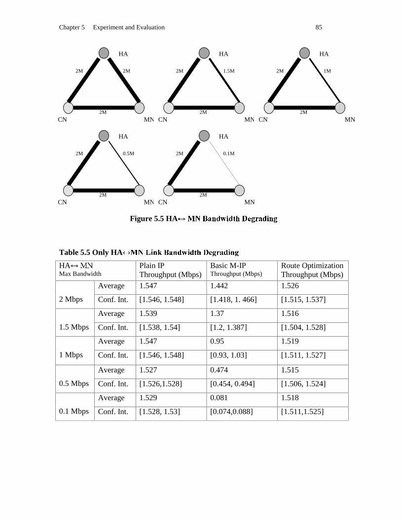
Chapter 5 Experiment and Evaluation 85
Figure 5.5 HA Ò�ÓyÔ7Õ�Ö�×%Ø:Ù;×#Ú>Û�ÜAÝ�Þ�ßDÕ�×#Ù;Ö�Þ
Table 5.5 Only HA à�áyâ7ã;ä#å�æ�ç�ä�è�é'ã�è�ê*ë�ì�í�î�ï�ç�è�ã�ä�î HA ð�ñ Max Bandwidth
Plain IP Throughput (Mbps)
Basic M-IP Throughput (Mbps)
Route Optimization Throughput (Mbps)
Average 1.547 1.442 1.526
2 Mbps Conf. Int. [1.546, 1.548] [1.418, 1. 466] [1.515, 1.537]
Average 1.539 1.37 1.516
1.5 Mbps Conf. Int. [1.538, 1.54] [1.2, 1.387] [1.504, 1.528]
Average 1.547 0.95 1.519
1 Mbps Conf. Int. [1.546, 1.548] [0.93, 1.03] [1.511, 1.527]
Average 1.527 0.474 1.515
0.5 Mbps Conf. Int. [1.526,1.528] [0.454, 0.494] [1.506, 1.524]
Average 1.529 0.081 1.518
0.1 Mbps Conf. Int. [1.528, 1.53] [0.074,0.088] [1.511,1.525]
CN
CN
MN
HA
CN MN
HA
CN MN
HA
MN
HA
CN MN
HA
2M 2M
2M
1.5M
2M
2M
2M
0.5M
2M
2M 2M
1M 2M
0.1M 2M

Chapter 5 Experiment and Evaluation 86
5.3.6.4 CN òôóöõ�÷�ø�ù�ú7û�ø�ü%ý:÷;ü�þ*ÿ���������û�ü�÷�ø��
Figure 6.6 CN � �����������������������������������
Table 5.6 CN "!$#&%�'�(�)�*�'�+�,�%�+�-�.�/�0�1�2�*�+�%�'�1 CN 354 Max Bandwidth
Plain IP Throughput (Mbps)
Basic M-IP Throughput (Mbps)
Route Optimization Throughput (Mbps)
Average 1.547 1.442 1.524
2 Mbps Conf. Int. [1.546, 1.548] [1.418, 1.466] [1.515, 1.533]
Average 1.42 1.447 1.394
1.5 Mbps Conf. Int. [1.419, 1.421] [1.431, 1.463] [1.388, 1.4]
Average 0.967 1.448 0.949
1 Mbps Conf. Int. [0.966, 0.968] [1.431, 1.465] [0.947, 0.951]
Average 0.481 1.443 0.472
0.5 Mbps Conf. Int. [0.48, 0.482] [1.425, 1.461] [0.465, 0.479]
Average 0.096 1.444 0.094
0.1 Mbps Conf. Int. [0.095, 0.097] [1.422, 1.466] [0.093, 0.095]
CN
CN
MN
HA
CN MN
HA
CN MN
HA
MN
HA
CN MN
HA
2M 2M
2M
2M
0.1M
2M
2M
2M
0.5M
1.5M 1M
2M 2M
2M 2M
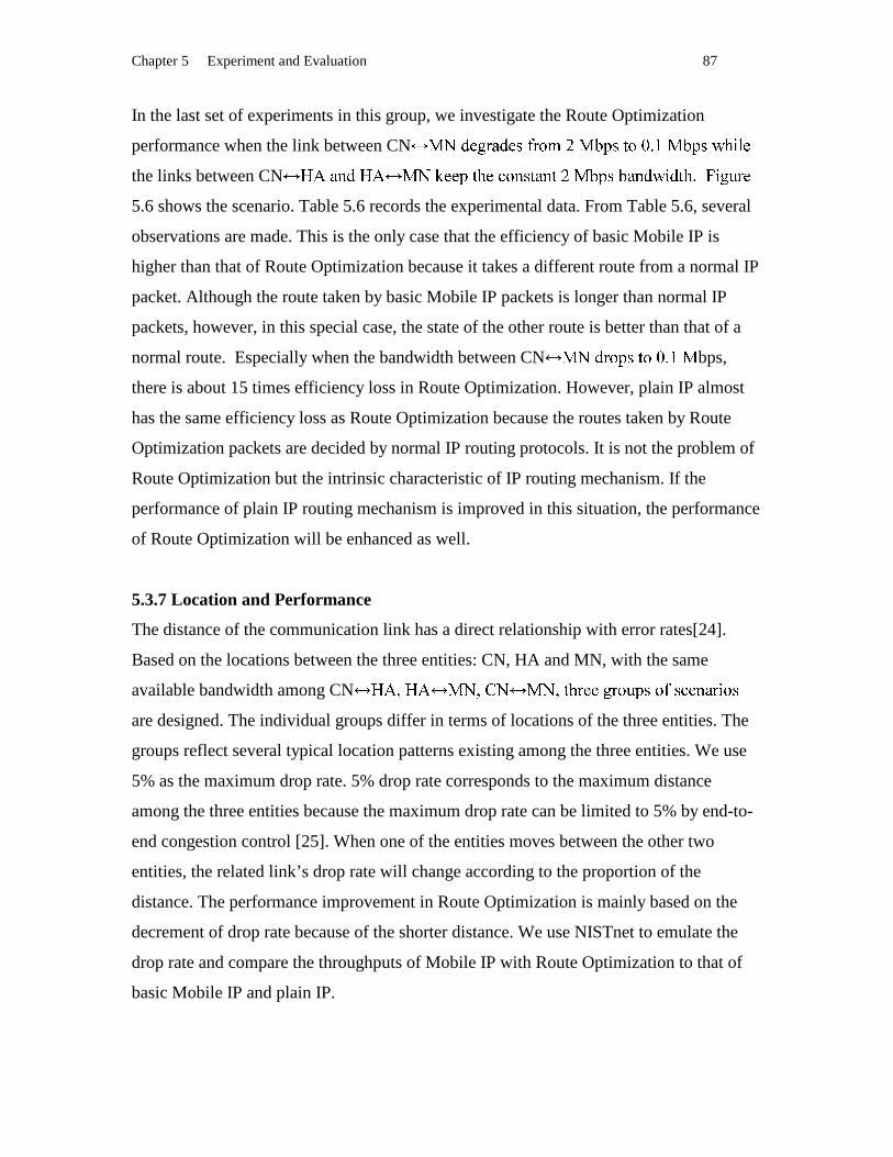
Chapter 5 Experiment and Evaluation 87
In the last set of experiments in this group, we investigate the Route Optimization
performance when the link between CN 687:9�;�<>=@?�9�;�ACBD=FE�GIHJ68K�LMAONPEJQ�RTSU68K�LMAOVXWMY�Z�;the links between CN [�\I]_^M`a[X\ b8c dMe�e_fJg�hMeji�k�^MlmgP]_^�gonJb5p�fMlOpM]_^M`�qsr�`�g�hMtauUr�v>w�[email protected] shows the scenario. Table 5.6 records the experimental data. From Table 5.6, several
observations are made. This is the only case that the efficiency of basic Mobile IP is
higher than that of Route Optimization because it takes a different route from a normal IP
packet. Although the route taken by basic Mobile IP packets is longer than normal IP
packets, however, in this special case, the state of the other route is better than that of a
normal route. Especially when the bandwidth between CN y8zI{�|@}�~M�O�P}J���T�Uy bps,
there is about 15 times efficiency loss in Route Optimization. However, plain IP almost
has the same efficiency loss as Route Optimization because the routes taken by Route
Optimization packets are decided by normal IP routing protocols. It is not the problem of
Route Optimization but the intrinsic characteristic of IP routing mechanism. If the
performance of plain IP routing mechanism is improved in this situation, the performance
of Route Optimization will be enhanced as well.
5.3.7 Location and Performance
The distance of the communication link has a direct relationship with error rates[24].
Based on the locations between the three entities: CN, HA and MN, with the same
available bandwidth among CN ���s���X� �8�s����� �8�s�������F���j�>�F�����M�C���������_�M�_�F�����are designed. The individual groups differ in terms of locations of the three entities. The
groups reflect several typical location patterns existing among the three entities. We use
5% as the maximum drop rate. 5% drop rate corresponds to the maximum distance
among the three entities because the maximum drop rate can be limited to 5% by end-to-
end congestion control [25]. When one of the entities moves between the other two
entities, the related link’s drop rate will change according to the proportion of the
distance. The performance improvement in Route Optimization is mainly based on the
decrement of drop rate because of the shorter distance. We use NISTnet to emulate the
drop rate and compare the throughputs of Mobile IP with Route Optimization to that of
basic Mobile IP and plain IP.
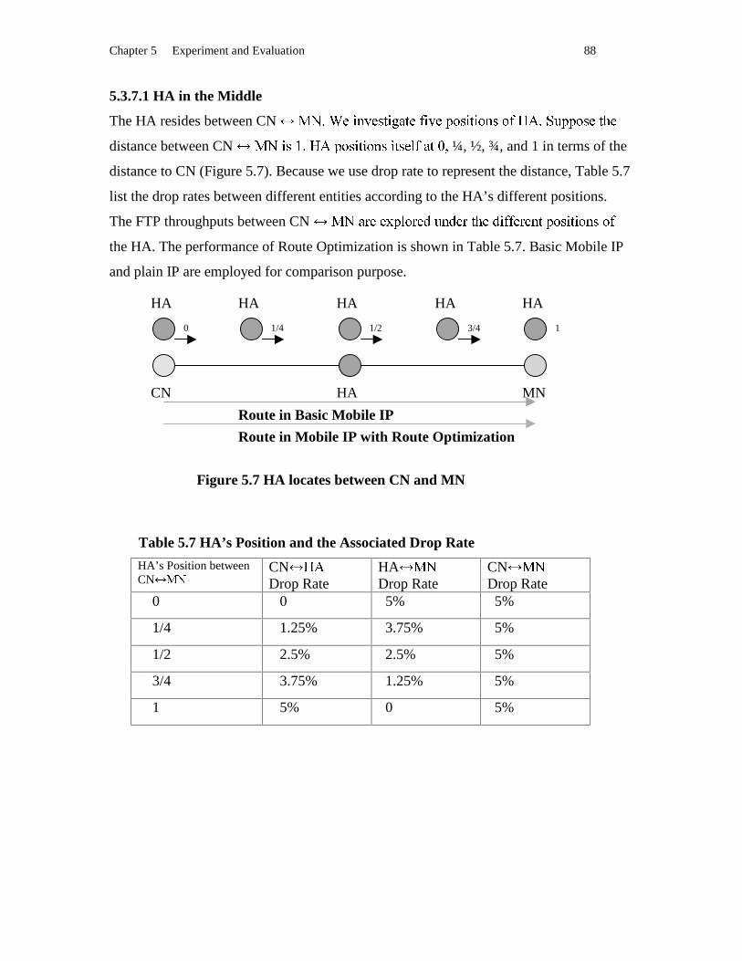
Chapter 5 Experiment and Evaluation 88
5.3.7.1 HA in the Middle
The HA resides between CN �8�s��� �j¡£¢�¤M��¥T¦§¡�¨ª©_¦§�j«m¡£¤M�¬M®�¥�¡£¦§¡�®�¢M¥C®�«°¯X±s��²�³�¬�¬M®�¥��¦�´M�distance between CN µ8¶:·�¸º¹�»�¼X½$¾M¿�¸F·ÁÀ§·�¿�ÂM¸C·£ÀP¸FÃ�Ä�ÅOÆ_À�Ç�È ¼, ½, ¾, and 1 in terms of the
distance to CN (Figure 5.7). Because we use drop rate to represent the distance, Table 5.7
list the drop rates between different entities according to the HA’s different positions.
The FTP throughputs between CN É8ÊIË_ÌFÍjÍ_ÎÐÏMÑ�Ò�ÌFÍ�ÓaÔ�ÕMÓ�Í_Ì�Ö�×MÍjÓ�Ø�ÙmÙ�Í_ÌFÍ_Õ�ÖoÏMÒ�Ú�Ø£Ö§Ø�Ò�ÕMÚCÒ�Ùthe HA. The performance of Route Optimization is shown in Table 5.7. Basic Mobile IP
and plain IP are employed for comparison purpose.
Figure 5.7 HA locates between CN and MN
Table 5.7 HA’s Position and the Associated Drop Rate
HA’s Position between CN Û�Ü
CN ÝXÞ Drop Rate
HA ß5à Drop Rate
CN á5â Drop Rate
0 0 5% 5%
1/4 1.25% 3.75% 5%
1/2 2.5% 2.5% 5%
3/4 3.75% 1.25% 5%
1 5% 0 5%
CN HA MN
Route in Basic Mobile IP
Route in Mobile IP with Route Optimization
0 1/4 1/2 3/4 1
HA HA HA HA HA

Chapter 5 Experiment and Evaluation 89
Table 5.8 HA Between the CN and MN
HA’s Position between CN ã8ä
Plain IP Throughput (Mbps)
Basic M-IP Throughput (Mbps)
Route Optimization Throughput (Mbps)
Average 1.412 1.313 1.332
0 Conf. Int. [1.411, 1.413] [1.312, 1.314] [1.331, 1.333]
Average 1.406 1.312 1.331
1/4 Conf. Int. [1.405, 1.407] [1.311, 1.313] [1.33, 1.332]
Average 1.408 1.31 1.33
1/2 Conf. Int. [1.407, 1.409] [1.281, 1.339] [1.303,1.357]
Average 1.411 1.299 1.332
3/4 Conf. Int. [1.41, 1.412] [1.298, 1.3] [1.331, 1.333]
Average 1.41 1.311 1.329
1 Conf. Int. [1.409, 1.411] [1.281, 1.341] [1.3, 1.358]
We can make the following observation from Table 5.8. When CN å8æ$çMè�éCèjê�ë�ìMémíPè_ì�ídistance and the three entities have the same bandwidth, no matter where HA is between
CN î5ïñð�ò�óMôò�ó�õFö�÷Mø>ó�ù�÷�ò�ö�úÐûüö�÷�òPôjýþù�òPÿ�� ÿ����_òPÿ�ö�� ÿ���Mö�ò��úmú�ô��_òPô ���� óMôjô�úmú�ÿ���ÿ�ô��������ö����Cö�úRoute Optimization vs plain IP is about 4%. The efficiency gains of Route Optimization
via basic Mobile IP is about 1.6%. Obviously, the performance of Route Optimization
does not show a big improvement in this case. However, at least, it does not decline.
5.3.7.2 CN in the Middle
MN has a constant distance to HA. Suppose the distance as logical value 1. CN exists in
five positions between MN ���������� ��!#"%$���!'&�(*)�+ ¼, ½, ¾, 1 in terms of the distance to
HA. In the five cases, the performance of Route Optimization is explored as compared to
basic Mobile IP and plain IP. Figure 5.8 shows the cases graphically. Table 5.10
demonstrates the experimental results.
We can make an observation about the efficiency gain of Route Optimization. As CN
becomes closer and closer to MN while the distance between HA ,.-�/0�0�1243�5�6287:9;6�7:<the efficiency gain of Route Optimization increases from 4.8% =�>�?A@;BDC�E'F�G�H�IC;J K d to
basic Mobile IP. Figure 5.8 displays the tendency. The experiment only considers the

Chapter 5 Experiment and Evaluation 90
increment of the drop rate as the distance increases. If a longer delay and other link
degradation’s factors are calculated based on longer distances, the efficiency gain of
Route Optimization will be greater than shown here.
Figure 5.8 CN locates between HA and MN
Table 5.9 CN’s Position and the Associated Drop Rate
CN’s Position between HA L.M
CN N�O Drop Rate
HA PRQ Drop Rate
CN SRT Drop Rate
0 0 2.5% 2.5%
1/4 0.625% 2.5% 1.875%
1/2 1.25% 2.5% 1.25%
3/4 1.875% 2.5% 0.625%
1 2.5% 2.5% 0%
HA CN MN
Route in Basic Mobile IP
Route in Mobile IP with Route Optimization
0 1/4 1/2 3/4 1
CN CN CN CN CN

Chapter 5 Experiment and Evaluation 91
Table 5.10 CN Between HA and MN
CN’s position between HA U.V
Plain IP Throughput (Mbps)
Basic M-IP Throughput (Mbps)
Route Optimization Throughput (Mbps)
Average 1.376 1.269 1.33
0 Conf. Int. [1.375, 1.377] [1.251, 1.287] [1.306, 1.354]
Average 1.383 1.213 1.365
1/4 Conf. Int. [1.382, 1.384] [1.18, 1.242] [1.345, 1.385]
Average 1.419 1.192 1.41
1/2 Conf. Int. [1.418, 1.42] [1.167, 1.217] [1.394, 1.426]
Average 1.456 1.128 1.419
3/4 Conf. Int. [1.455, 1.457] [1.092, 1.164] [1.381, 1.457]
Average 1.509 1.087 1.468
1 Conf. Int. [1.508, 1.51] [1.021, 1.153] [1.456, 1.48]
0.00%
5.00%
10.00%
15.00%
20.00%
25.00%
30.00%
35.00%
40.00%
0 0.25 0.5 0.75 1
Distance
Eff
icie
ncy
Gai
n o
r L
oss
RO Efficiency Gainsvs basic Mobile IP
RO EfficiencyLosses vs Plain IP
Figure 5.9 Route Optimization Efficiency (CN in the Middle)
5.3.7.3 MN in the Middle
HA WX�YZ�['Z]\�^�_[A`:Z�_�`*a�b�[8`cZ�_\�d�e�f.X�gh^�id�[kjd�`�l�d�d�_nm�o WpX�e�qrd][#d�s%d�\�`*tub�idrepresentative positions to investigate the performance tendency while the MN moves

Chapter 5 Experiment and Evaluation 92
from HA to CN. The distance between HA and CN is expressed as logical value 1. The
distances from MN to HA are displayed on Figure 5.10 as logical values: 0, ¼,½, ¾, 1.
Figure 5.10 MN locates between HA and CN
Table 5.11 MN’s Position and the Associated Drop Rate
MN’s Position between HA vw
HA xy Drop Rate
HA zR{ Drop Rate
MN |} Drop Rate
0 2.5% 0% 2.5%
1/4 2.5% 0.625% 1.875%
1/2 2.5% 1.25% 1.25%
3/4 2.5% 1.875% 0.625%
1 2.5% 2.5% 0%
HA MN CN
Route in Basic Mobile IP
Route in Mobile IP with Route Optimization
0 1/4 1/2 3/4 1
MN MN MN MN MN

Chapter 5 Experiment and Evaluation 93
Table 5.12 MN Between HA and CN
MN’s position between HA ~�
Plain IP Throughput (Mbps)
Basic M-IP Throughput (Mbps)
Route Optimization Throughput (Mbps)
Average 1.353 1.271 1.315
0 Conf. Int. [1.352, 1.354] [1.241, 1.301] [1.286, 1.344]
Average 1.414 1.219 1.383
¼ Conf. Int. [1.413, 1.415] [1.182, 1.256] [1.369, 1.397]
Average 1.426 1.197 1.41
½ Conf. Int. [1.425, 1.427] [1.176, 1.218] [1.398, 1.422]
Average 1.469 1.135 1.469
¾ Conf. Int. [1.468,1.47] [1.11, 1.16] 1.468, 1.47]
Average 1.509 1.087 1.499
1 Conf. Int. [1.508, 1.51] [1.077, 1.098] [1.487, 1.511]
0.00%
5.00%
10.00%
15.00%
20.00%
25.00%
30.00%
35.00%
40.00%
0 0.25 0.5 0.75 1
Distance
Eff
icie
ncy
Gai
n o
r L
oss
RO Efficiency Gains vsbasic Mobile IP
RO Efficiency Losses vsPlain IP
Figure 5.10 Route Optimization Efficiency (MN moves from HA to MN)
Table 5.12 records the TCP throughputs of CN �.��������n�.���h������'�;�h������%��]�u����positions while Route Optimization is being used as the mobility protocol, or basic

Chapter 5 Experiment and Evaluation 94
Mobile IP being used as the mobility protocol. We also use another static host in the
same location as MN to transfer a file from CN by using plain IP for comparison
purposes. Two observations can be made from the table. When MN moves toward CN,
the throughput of Route Optimization increases from 1.315 to 1.499 while the throughput
of basic Mobile IP decreases from 1.271 to 1.087. The efficiency gain of Route
Optimization rises from 3.5% to 37.9% as compared to basic Mobile IP. The efficiency
losses compared to plain IP is not bigger than 2.8%. Figure 5.10 shows the tendency as
the MN moves.
5.4 Result Analysis
The above experiments demonstrate that the performance improvement of Mobile IP with
Route Optimization depends on the link’s states and the entities’ distances as well as the
MN’s moving patterns. The minimum efficiency gain is 3.3% and the maximum
efficiency gains can reach 17 times. When the link between CN ��������������%�������n���MN degrades, Route Optimization enjoys the maximum benefits. While MN moves away
from HA, the closer the MN is to CN, the greater benefits Route Optimization obtains.
When it comes to the efficiency losses of Route Optimization as compared to plain IP, no
matter what scenarios it is, it is always below 3%. In most cases, it conforms to the
theoretical calculation value 1.4% by adding the tunneling overhead to plain IP packets.
Comparing our test results to related work done at the National University of Singapore
[23], their experiments demonstrates that the triangle routing causes 80% more time to
transfer a file, or the throughput degrades from 1 to 1/(1+0.8) ���� ¢¡�£� �¤p¥¦]¦�§u§u¨%©�¨�¦;ª©�«�¬%�®#®of basic Mobile IP because of triangle routing is (1-0.56)/1̄±°�°�²´³�µ·¶�¸u¹»º�¼½%¾k¿�ÀÂÁ�Ã�Ädeduce that Route Optimization efficiency gain should be about 44%. Their test is based
on 10 Mbps Ethernet and one scenario. The performance of Route Optimization can only
be deduced. Our experiment chooses more realistic access methods for the MN,
WaveLan, and tests on 10 different scenarios to investigate Route Optimization
performance more intensively. Our experiment shows that the 44% gain is only one of
the specific cases among different scenarios and various gains. Researchers at the
National University of Singapore implement the basic Mobile IP code in the Linux kernel
space. Their TCP throughput has a 44% loss compared to plain IP. In our wireless access

Chapter 5 Experiment and Evaluation 95
environment, when the wireless bandwidth becomes the bottleneck of the whole
transferring process, the TCP throughput based on Route Optimization has only a 3% loss
as compared to plain IP even though our implementation exists in the Linux user space.

Chapter 6 Conclusion and Future Work 96
Chapter 6
Conclusion and Future Work In order to allow portable device users to access network services anywhere and anytime
regardless of their movement, mobility support in a network is more desirable than ever.
Many approaches are investigated, some of which provide micro mobility by focusing on
adaptive routing technologies while others provide macro mobility. As for macro
mobility, solutions mainly concentrate on how to provide mobility based on the existing
routing mechanism in the Internet TCP/IP infrastructure. Among them, Mobile IP is a
promising approach. To overcome the routing anomaly existing in Mobile IP, Route
Optimization in Mobile IP is presented. The implementation of Mobile IP or Mobile IP
with Route Optimization varies in terms of different operating system support as well as
different design considerations and architectures.
In the thesis, we presented our experience with the implementation of Route
Optimization based on the basic Mobile IP implementation. Based on our
implementation, the performance of Route Optimization is evaluated via various network
conditions. For comparison purposes, basic Mobile IP and plain IP are also employed. In
this chapter, we will summarize our work, draw some conclusions and provide
suggestions for future work.
6.1 Contr ibutions
We classified the contribution performed in this thesis into four categories. The first part
is our exploration to implement Route Optimization on a Linux platform in C++. The
functionality and our approach performed in the home agent and the correspondent node
are presented. The second part is a performance evaluation to Route Optimization. The
third part presents the role for Mobility in IPv6. The fourth part is two enhancements
suggested by us to the draft of Mobile IP with Route Optimization.

Chapter 6 Conclusion and Future Work 97
6.1.1 Implementation of Route Optimization
6.1.1.1 Home Agent Traffic Monitor ing
In order to inform a correspondent node of the current location of its mobile peer, the
home agent must monitor any traffic destined to the mobile nodes that belong to the
home network. Because Linux lacks on API (Application Program Interface) to achieve
this goal, a unique approach is employed in this thesis. We utilized the IP firewall model
as our traffic monitor. The ipchains is used to set the requirements into the Linux kernel.
The file ip_fw.c in the Linux kernel is enhanced to capture the address of the
correspondent node that is communicating with a mobile node. The Linux system call
ioctl() is extended to provide an approach to transfer data from the kernel space to the
user space.
6.1.1.2 Home Agent Binding Update Management
The Binding Update Management module organizes and sends Binding Update messages
to a correspondent node if the home agent notices that the correspondent node is routing
its traffic through the home network. The function is implemented in the user space using
UDP socket calls.
6.1.1.3 Correspondent Node Binding Updating
The Binding Updating module in a correspondent node is responsible for listening to the
Binding Update message from the mobile node’s home agent, processing the message
and calling related modules.
6.1.1.4 Correspondent Node Binding Cache Management
The Binding Cache Management module in a correspondent node is responsible for
maintaining the binding cache, including adding a new entry, deleting an expired entry,
and acquiring, modifying, or replacing an existing entry in the binding cache.
6.1.1.5 Correspondent Node Traffic Control
The Traffic Control module filters out the traffic destined to mobile nodes whose location
information is cached in the correspondent node and tunnels the traffic.

Chapter 6 Conclusion and Future Work 98
6.1.2 Evaluating Route Optimization Performance
Our work provides quantitative evaluation of the performance of Route Optimization,
compared to basic Mobile IP and plain IP. The evaluation allows us have an insight look
at the efficiency gains via basic Mobile IP under various network conditions and provides
convincing support for Route Optimization in Mobile IP.
6.1.3 Supporting Mobility in IPv6
The development of Route Optimization techniques for IPv4 has played an important role
in the development of mobility support for IP Version 6 [27, 12]. Route Optimization is
intrinsic in IPv6. There are several similar aspects between Route Optimization in IPv4
and Mobility in IPv6, such as route optimality, or Binding Updates in the correspondent
node. Because the popular deployment of IPv6 still needs some time, the deployment of
Route Optimization in IPv4 will provide a reference to performance evaluation of IPv6 in
advance and determine common problems in both protocols.
6.1.4 Enhancing Route Optimization Protocol
6.1.4.1 Binary Exponential Backoff Algor ithm (BEBA)
In the absence of Route Optimization support in a correspondent node, sending out the
Binding Update message repetitively by a home agent will degrade the home agent’s
performance and waste network bandwidth and the home agent’s resources. Especially
during the transient period, a great number of correspondent nodes still lack the Route
Optimization support. The waste of resources and the degradation of performance will be
prominent. In the existing Route Optimization draft, there is no specific consideration of
these problems. The thesis suggests the Binary Exponential Backoff Algorithm to
increase the interval between two successive Binding Update messages to the same
correspondent node exponentially. If a correspondent node does not support the binding
cache, the home agent will stop sending the Binding Update message to the
correspondent node when the interval time achieves a predefined value. The Binary
Exponential Backoff Algorithm will keep sending the Binding Update message to a
Chapter 6 Conclusion and Future Work 99
correspondent node if previous messages are lost because of congestion or intermediate
router overflow. It is an effective solution to the absence of the Route Optimization
support in correspondent nodes during the transient period.
6.1.4.2 Binding Cache Management Strategies
Binding Cache Management Strategy is an implementation technique. When a binding
cache is full, there are several strategies to replace an existing entry by a new adding
entry. Similar to the operating system memory management, the thesis considered three
mechanisms: FIFO, LRU, and LFU. In the implementation, we chose FIFO because of its
simplicity.
6.2 Conclusion
The implementation of Route Optimization varies with different underlying operating
systems. We chose Linux as platform because of consideration to keep consistency with
the implementation platform of basic Mobile IP as well as its various advantages such as
open source code, Unix API, and popularity. We implemented the correspondent node’s
functionality in the user space to relieve the deployment difficulty. Because of the lack of
support to monitor the traffic in the user space, the kernel module ip_fw.c is enhanced.
Our practice provides an implementation sample of Route Optimization in Mobile IP.
The wide spread of Route Optimization support in correspondent nodes is a non-trivial
task. Considering about the deployment difficulties, evaluation of the efficient gains in
Route Optimization can present effective evidence to the choice between Mobile IP with
Route Optimization and basic Mobile IP. Based on our implementation, the performance
of Route Optimization is analyzed quantitatively under diverse network conditions. Our
conclusion is that the efficiency gain in Route Optimization is influenced by network
conditions but it is considerable in most situations. The performance tradeoff existing in
the user space implementation is insignificant under a wireless access environment
because the bottleneck of the system is wireless bandwidth instead of processor speed in
the home agent, the foreign agent, the mobile node and correspondent node. Comparing
the Mobile IP’s kernel space implementation which were done in National University of
Singapore[19], our experimental result shows that there is no penalty of our user space
Chapter 6 Conclusion and Future Work 100
implementation. In our wireless access environment, when the wireless bandwidth
becomes the bottleneck of the whole transferring process, the TCP throughput based on
Route Optimization has only a 3% loss as compared to plain IP even though our
implementation exists in the Linux user space. It is the direct consequence of a well-
conceived architecture design and artful implementation in this thesis.
6.3 Future Work
Another important aspect of Route Optimization is smooth handoff. Packets on the fly
will be received by the previous foreign agent and forwarded to the new foreign agent
when a mobile node is moving from one network to another network. Smooth handoff
will reduce the packet loss during the movement. However, more work such as creating
the visiting list in a foreign agent and handling the Binding Update message from the new
foreign agent to the previous foreign agent, is necessary. The performance of smooth
handoff needs to be evaluated to decide whether smooth handoff is worthy being added to
Route Optimization.
Security Association in Route Optimization is more complex than that in basic Mobile IP
because of increasing messages that affect the packet routing to a mobile node [3].
Especially many correspondent nodes need to share secret keys with home agents. A
general solution to the problem may depend on the appearance of an Internet public key
infrastructure. In this implementation, the authentication algorithm is MD5 and all shared
secret keys are assigned in advance.
In the thesis, three binding cache management strategies are discussed. The performance
of the strategies needs be evaluated in the future.
In order to receive data from the kernel space, the ioctl() system call is extended and the
Binding Update module in a home agent keeps polling the kernel cache via a raw socket.
If the kernel module can send out a signal to the Binding Update module when the data is
prepared instead of the periodic polling, the efficiency of the Binding Update module will
increase.

Reference 101
Reference [1] Ashutosh Dutta, Fraamak Vakil, Jyh-cheng Chen, Miriam Tauil, Shinichi Baba,
Nobuyasu Nakajima, Henning Schulzrinne “Application Layer Mobility Management
Scheme for wireless Internet” , Conference Proceedings of 3Gwireless’ 2001, May30-
June 2, 2001, San Francisco, U.S.A, pp.379-385.
[2] Douglas E. Comer, “ Internetworking with TCP/IP volume I. Principles, Protocols and
Architecture” Prentice Hall, 2000, ISBN # 0130183806
[3] Charles E. Perkins, David B. Johnson “Route Optimization for Mobile IP” , Cluster
Computing, Volume1, 1998, pp.161-175
[4] Hong Li, Gerard Pieris “Mobile Routing for Large Scale All-IP Wireless Network” ,
Mobile Computing and Communications Review, Volume 4, Number 4, 2001, p.36-44
[5] Andras G. Valko “Cellular IP: A New Approach to Internet Host Mobility” , ACM
Computer Communication Review, January 1999, ISSN # 0146-4833
[6] Zach D. Shelby, Dionisios Gatzounas, Andrew Campbell, Chieh-Yih Wan, “Cellular
IPv6” , Internet Draft, <draft-schelby-cellularipv6-01.txt>, July 2001, Work in Progress.
[7] A. T. Campbell, Javier Gomez, “An Overview of Cellular IP” , IEEE Wireless
Communications and Networking Conference (WCNC’99), New Orleans, September
1999, pp.606-611.
[8] Elin Wedlund, Henning Schulzrinne, “Mobility Support using SIP” , Proceedings of
the second ACM international workshop on Wireless Mobile Multimedia, August 20,
1999, Seattle, WA, USA, pp.76-82.
[9] Mark Handley, Eve Schooler, H. Schulzrinne, Jonathan Rosenberg, “Session Initiaion
Protocol” , RFC 2543
[10] Alex C. Snoeren, Hari Balakrishnan, “An End-to-End Approach to Host Mobility” ,
MOBICOM 2000, Boston MA USA, pp.155-166.
[11] Charles E. Perkins, David B. Johnson, “Mobility Support in IPv6” , Proceedings of
the Second Annual International Conference on Mobile Computing and Networking
(MobiCom’96), November 10-12, 1996, Rye New York USA, pp.1-14.
Reference 102
Å�ÆÈÇÊÉ]ËÂÌÎÍÏÑÐÓÒÕÔ×ÖÈØÚÙÜÛÝÎØÞÛßpàÙÜÌ�á;âäãÞÝæåÊãÞáèç�ÏäÛÝÎßÚéëêìØÚíÊÏÑâäÏ î8ïRðÜñÜòÊòÊØÚáóîôÏäÛöõ;åÈÍ÷Êø ß�ùúÐÊáèÌüûAî ýèÏäãëîuû�ýþ ØÞíÊÏÑâÑãÿÏÑòÊýèÏÑòÈÍ÷Êý Æ � Ô î���î��úßpÇ�ÖÈñâ ïöÇ������Êß��±ØÚáèç ÏäÛöòÊáèØÊáèãÿÝÎÝ�Ô[13] Charles E. Perkins, “Mobile networking in the Internet” , Mobile Networks and
Applications 3, 1998, pp.319-334.
[14] Pravin Bhagwat, Charles Perkins, Satish Tripathi, “Network Layer Mobility: An
Architecture and Survey” , IEEE Personal Communications, June 1996, pp54-64
[15] John Ioannidis, Dan Duchamp, Gerald Q. Maguire Jr., “ IP-based Protocols for
Mobile Internetworking” , Proceedings of ACM SIGCOMM, 1991, pp235-245
[16] Charles E. Perkins, “Mobile IP Design Principles and Practices” , Addison Wesley,
1997, ISBN 0201634694
[17] Charles E. Perkins, “ IP Mobility Support for IPv4” RFC2002, October 1996
[18] Charles Perkins, David B. Johnson, “Route Optimization in Mobile IP” , < draft-ietf-
mobileip-optim-11.txt >, work in progress, 6 September 2001
[19] William Stallings, “Operating Systems Internals and Design Principles” , Prentice-
Hall International, Inc, 1998
[20] Gary Nutt,”Operating systems : A Moderm Perspective” , Addison-Wesley, 2000
[21] John A. Selmys, “Linux – The New kid on the Block” ,
http://titanic.senecac.on.ca/comdex2000
[22] Bruce Powel Douglass, “Doing Hard Time: Developing Real-Time System with
UML, Objects, Frameworks, and Patterns” , Addison-Wesley, May 1999, ISBN
0201498375.
[23] Foo Chun Choong, “TCP performance in Mobile-IP” ,
http://mip.ee.nus.edu.sg/mip.html
[24] Reiger, S., "Error Probabilities of Binary Data Transmission Systems in the Presence
of Random Noise," IRE National Convention Record, Part 8, Information Theory, 1953,
pp. 72-79
[25] Floyd, S., and Fall, K., Router Mechanisms to Support End-to-End Congestion
Control. Technical report, February 1997.
[26] P. Dykstra, “Protocol Overhead”, � ����������������� �����! �"#$ %�&�'���(�*)�"%+,��-.���0/21 ��#0 3����"540 %�!�$ %�&�6�

Reference 103
[27] Jinyang Li, Charles Blake, Douglas S. J. De Couto, Hu Imm Lee, Robert Morris,
“Capacity of Ad Hoc Wireless Networks” , ACM SIGMOBILE 7/01 Rome, Italy, 2001,
pp.61-69, ACM ISBN 1-58113-422-3/01/07

Appendix A IP Based Mobility Proposals 104
Appendix A
IP Based Mobility Proposals Mobile IP evolves from several previous proposals. All these proposals focus on how to
modify the IP layer and add new features or new entities to support mobility in the
Internet. In this appendix, we will introduce four ancestors of Mobile IP. All these
proposals are IP based mobility proposals.
A.1 Sony Mobile IP Proposal
When a mobile node connects to a foreign network, it will obtain a temporary address,
serving as location address, from a local address server. Then, it will notify the home
network gateway of the new location and identifier association. And every packet send
out from the mobile node will carry this mapping information by using IP options to put
two source addresses, one is the identifier address, another is the location address, in the
source address field. Routers (also called Sony gateways) that forward the packet will
cache this mapping information. This is the propagating cache method, which distributes
the LD information throughout the network besides sending the LD information to the
home network. A correspondent node sends out a packet with identifier address as
destination address. The packet should be routed to the home network of the mobile node.
On its way to the home network, if any transit router (a Sony gateway) has a LD cache
about the mobile node, the packet will be intercepted and is forwarded to the mobile
node’s current location. Otherwise, the packet will arrive at the home gateway, and then
it is forwarded to the mobile node [A.4,A.5,A.6].
From the point of the abstract Mobile IP architecture view, the LD cache is distributed
among routers. ATA collocates in routers with LD caches. In fact, ATA is distributed
among networks. ATA at the home network is used if there is no ATA along the way to
the home network. FA is collocated with the mobile node in this proposal.
The main advantages of the Sony Mobile IP proposal are:
(1) If the communication is activated by a mobile node first, packets will always go
through an optimal route because correspondent hosts get the location information

Appendix A IP Based Mobility Proposals 105
and the gateway of a correspondent network also updates its LD cache by using the
location information contained in the packet. The gateway of the correspondent
network will act as ATA. Then the return packet will travel an optimal route.
(2) The system is robust. This is the advantage of any distributed system. In the Sony
proposal, LD caches and ATA are distributed throughout the Internet.
(3) Large amounts of correspondent nodes do not need to be modified.
The main disadvantages of the Sony Mobile IP proposal are:
(1) Maintaining the consistency of LD caches make the system complex. When a mobile
node migrates, purging all obsolete cache entries network-wide will be extremely
difficult. If using time-outs, the time-out length is difficult to determine.
(2) All routers who function as Sony gateways need to be modified. If the MN number is
big, the LD cache in every router will be extremely large. It is not practical.
Therefore, the scalability of the Sony IP is poor.
(3) Every MN needs a temporary address to reflect its current location. It makes the
originally scarce address space more scarce.
A.2 Columbia Mobile IP Proposal
The Columbia proposal has two versions; one is intended for local networks. The other,
so called popup Columbia Mobile IP, is a modified version for wide-area networks [A.2,
A.7]. A new mobile facility is introduced in the Columbia proposal. It is called an MSR
(Mobile Subnet Router). These MSRs construct a virtual mobile subnet. When a MN
registers in a MSR, the MSR is responsible for spreading the MN’s location information
and forms a LD directory for this MN. In this schema, all MNs that register in the same
MSR will share a common location address, the MSR IP address. When a packet, sent to
an MN, arrives at the nearest MSR, the MSR will check its LD to find out if it has the
location and identifier mapping of the destination identifier address. If the MSR does not
have the mapping, it will broadcast its query to all MSRs. The MSR who has this
mapping information will answer the query. The packet will be sent to the MSR who
claims to have the MN registered. MSRs can cache the LD information for future use.
These caches are purged periodically. In the Columbia schema, MSRs act as both ATA
Appendix A IP Based Mobility Proposals 106
and FA. For packets addressed to mobile nodes in its coverage area, an MSR acts as a
FA. For packets addressed to other mobile nodes, it acts as an ATA [A.1]. The LD cache
is distributed. There is no fixed home network. A current network is a home network. The
main difference between Columbia Mobile IP and Popup Columbia Mobile IP is that
there is a fixed home network for each mobile node in the popup Columbia proposal. The
Columbia proposal works only for small networks because all MSRs have to
communicate with each other frequently. In a wide-area network, the number of MSRs
will be large, the frequent communication between all these MSRs will be extremely
expensive, and managing all these LD cache is not easy [A.2, A.7].
The Popup Columbia Proposal is a wide-area version. The home network concept is
introduced. A MN has a home network. The MSR in the home network takes charge of
the LD of all mobile nodes belonging to the home network. When a MN arrives at a new
location, it acquires a temporary address and registers with the MSR in its home network.
The MSR acts as an ATA. The MN acts as a FA for itself. Every packet sent to the MN
will arrive at the MSR in the home network. The MSR acts as ATA to look up the LD
and encapsulates and tunnels the packet to the MN.
The main advantages of the Columbia Proposal are:
(1) Existing hosts and routers do not need to be modified.
(2) All mobile nodes registering in a MSR share a common location address. Scarce
address space is saved.
(3) Packets arrive at a destination by optimal route.
(4) It is suitable to small wireless networks.
The main disadvantage of the Columbia proposal is:
A new mobile facility (MSR) has to be added to the network. MSRs need to
communicate with each other frequently, if the number of MSRs is large and the MSRs
are separated in a large geographically area, the communication is expensive. So,
scalability is not good. It is not a good schema for wide-area networks.
The main disadvantage of the Popup Columbia proposal is:
When a mobile node is away from its home network, packets sent to it always travel by a
sub-optimal route. It increases the network traffic.

Appendix A IP Based Mobility Proposals 107
A.3 LSR Mobile IP Proposal
The LSR Mobile IP proposal is based on the use of an existing IP option: LSR. It uses a
Mobile Router (MR) relative to Mobile nodes in their home network. There are also one
or more mobile access stations (MAS) in each foreign network. When a MN walks into a
wireless cell, it attaches to a wireless access station. Then, the address of the MAS
represents the location address of this mobile node. The MN will inform its home
network MR of the current MAS address. The home network MR updates its route table.
When a correspondent host sends a packet to the home network, the MR will insert an
LSR option in the packet, specifying the current location address (MAS address) as a
transit address. The packet will arrive at the MN via the MAS. In the reply packet, the
MN will define MAS as first transit router via LSR option. When the reply packet
arrives, the correspondent host reverses the LSR and sends all outgoing packets with LSR
option, using the MAS address (MN Location address) as transit address. Subsequent
packets originating from the stationary host will be automatically routed along an optimal
path [A.8, A.9, A.3] .
In this proposal, there is a main LD, stored in MR, after that, every packet carries a LD
entry that will be used immediately. Therefore, a correspondent host has an on-demand
LD entry for currently communicating MNs. LD is distributed on-demand. At first, MR
acts as ATA. After the first reply packet from MN arrives at the correspondent node, the
correspondent host will act as ATA for itself. MASs serve as FA.
The main advantages of the LSR proposal are:
(1) Packets are almost routed along optimal path, except that the first packet in a session
will go through MR.
(2) LD is distributed on-demand. There is no LD cache consistency problem. Scalability
is good.
The main disadvantages of the LSR proposal are:
(1) Packets with LSR have low priority in routers. When traffic is heavy, this kind of
packet will be dropped.
(2) Most hosts do not support LSR reversal because of security problems.
(3) New mobile facilities (MR, MAS) have to be added to the system.

Appendix A IP Based Mobility Proposals 108
A.4 IBM Mobile IP Proposal
In the IBM Mobile IP proposal, new network facilities MR and MSR also need to be
added just as in the LSR proposal. The main difference is that encapsulation is used
instead of LSR. Therefore, a correspondent node can not use LSR reversal. Every packet
has to go through MR in the home network to get to MN [A.1, A.10]. This is the original
version of the IETF Mobile IP proposal. We have discussed it in the Chapter 2.
Appendix A Reference
[A.1]. Pravin Bhagwat, Charles Perkins, Satish Tripathi, “Network Layer Mobility: An
Architecture and Survey” , IEEE Personal Communications, June 1996, pp54-64
[A.2]. John Ioannidis, Dan Duchamp, Gerald Q. Maguire Jr., “ IP-based Protocols for
Mobile Internetworking” , Proceedings of ACM SIGCOMM, 1991, pp235-245
[A.3]. S. Deering and R. Hinden, Internet Protocol, Version 6 (IPv6) specification, RFC
1883 (December 1995)
[A.4]. F. Teraoka, Y. Yokote, and M. Tokoro, “A Network Archtecture providing Host
Migration Transparency” , Proc ACM SIGCOMM, Sept.1991, pp.209-220
[A.5]. F. Teraoka, M. Tokoro, “Host Migration Transparency in IP Networks” Comp.
Comm. Review, Jan 1993 pp.45-65
[A.6]. F. Teraoka et al. “VIP: A Protocol Providing Host Mobility” , comm. ACM vol37
no.8 Aug 1994
[A.7]. J. Ioannidis and G.Q. Maguire Jr., “The Design and Implementation of a mobile
Internetworking Archetecture” Proc. Winter USENIX, San Diego, CA Jan 1993, pp.491-
502
[A.8]. C. Perkins and P. Bhagwat, “A Mobile Networking System Based on Internet
Protocol” , IEEE Personal Communication Magzine vol1 no.1 Feb. 1994, pp.32-41
[A.9]. D.B. Johnson “Mobile Host Internetworking Using IP Loose Source Routing”
Tech. Rep. CMU-CS-93-128, Carnegie Mellon University, Pittsburgh, PA, Feb, 1993
[A.10]. Andrew Myles, David Skellern, “Comparing four IP based mobile host
protocols” , Computer Networks and ISDN system 26(1993) pp.349-355
Appendix B Multicast Support for Mobile Hosts 109
Appendix B
Multicast Suppor t for Mobile Hosts In this appendix, we will discuss some approaches to support multicast service for mobile
hosts.
B.1 Abstract Function and Architecture in Multicast Suppor t
Multicast is a mechanism for efficient one-to-many communication in which the source
transmits a single packet, and the network performs the task of delivering the packet to
multiple destinations. For fixed host networks, multicast is achieved by constructing a
delivering tree. Multicast applications such as weather reports, travel information and
stock market reports may become widely used by mobile users. Multicast addresses are
defined independent of location and use an address class separate from the normal unicast
addresses. According to this characteristic, mobility should not be a problem for
multicast. However, all existing multicast routing proposals (DVMRP, MOSPF, CBT,
and PIM)[B.3] implicitly assume stationary hosts when configuring the multicast delivery
trees. How to achieve multicast service for mobile nodes becomes a challenging problem.
For a MN that wishes to receive a group multicast datagram, it should join the group. We
think the delivery trees with MNs as receivers are actually dynamic delivery trees. The
branches and leaves will change along with the node’s mobility. MNs have to choose a
place to describe their membership. Where a MN describes its membership decides the
structure and charactistics of the dynamic tree. Because the network must deal with
dynamic group membership, can we make use of it to deal with the dynamic location of
mobile host? We can declare the MN’s group membership at the home network, declare
the membership at the current attached network or declare the membership at several
combined networks. Different methods will make the dynamic tree grow in different
ways. We call the declaration network the dynamic tree’s growth point. Different
declaring methods will choose different growth points. This is an abstract architecture of
the multicast support for mobile hosts. All multicast proposals for mobile hosts can be
describe by this abstract architecture. We will introduce them in detail in this appendix.
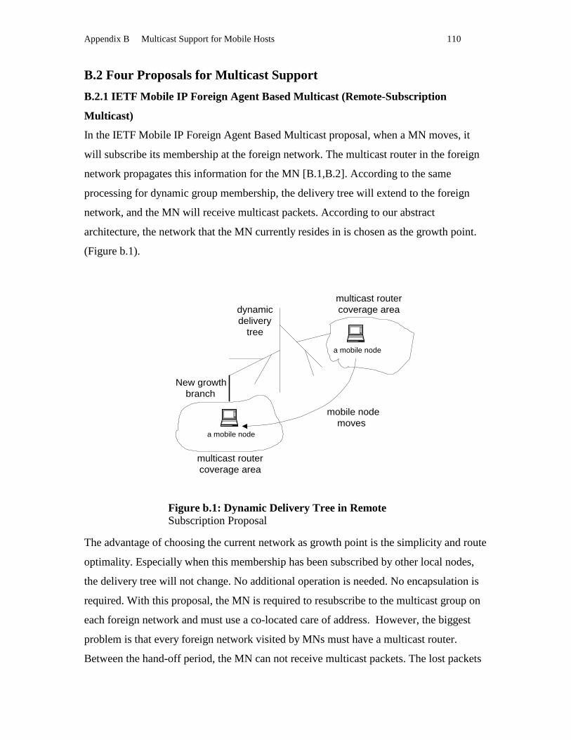
Appendix B Multicast Support for Mobile Hosts 110
B.2 Four Proposals for Multicast Suppor t
B.2.1 IETF Mobile IP Foreign Agent Based Multicast (Remote-Subscr iption
Multicast)
In the IETF Mobile IP Foreign Agent Based Multicast proposal, when a MN moves, it
will subscribe its membership at the foreign network. The multicast router in the foreign
network propagates this information for the MN [B.1,B.2]. According to the same
processing for dynamic group membership, the delivery tree will extend to the foreign
network, and the MN will receive multicast packets. According to our abstract
architecture, the network that the MN currently resides in is chosen as the growth point.
(Figure b.1).
The advantage of choosing the current network as growth point is the simplicity and route
optimality. Especially when this membership has been subscribed by other local nodes,
the delivery tree will not change. No additional operation is needed. No encapsulation is
required. With this proposal, the MN is required to resubscribe to the multicast group on
each foreign network and must use a co-located care of address. However, the biggest
problem is that every foreign network visited by MNs must have a multicast router.
Between the hand-off period, the MN can not receive multicast packets. The lost packets
Figure b.1: Dynamic Delivery Tree in Remote Subscription Proposal
a mobile node
a mobile node
multicast routercoverage area
multicast routercoverage area
dynamicdelivery
tree
New growthbranch
mobile nodemoves

Appendix B Multicast Support for Mobile Hosts 111
will affect the quality of service. If there are many MNs, then the dynamic tree will be
reconfigured frequently. This will seriously increase the multicast router’s burden. If the
MN is highly mobile, packets will be lost owing to the set-up time associated with
multicast subscription. Therefore, if the host is likely to be stationary for an extend period
of time, the option is preferred. As [B.3] said: “Remote subscription does provide the
most efficient delivery of multicast packets, but this service may come at a high price for
the networks involved and the multicast routers that must manage the multicast tree. For
hosts that want guaranteed two-way communication with the multicast group and are
unable to acquire a co-located address, or hosts that are highly mobile, a different method
is needed that will not overload the multicast routers.”
B.2.2 IETF Mobile IP Home Agent Based Multicast (Bi-Directional Tunnelling
Multicast)
In the IETF Mobile IP Home Agent Based Multicast proposal, when a MN is roaming in
a foreign network, multicast packets will be encapsulated by the home agent and
delivered to the MN by the same tunneling mechanism as other unicast packets. The MN
only subscribes its multicast group membership to the multicast router in its home
network. Its multicast group membership is transparent to any foreign network. The FA
will forward the multicast packets in a similar way to unicast packets[B.1,B.2]. In this
Figure b.2 The Dynamic Delivery Tree in Bi-Directional Tunnelling Proposal
mobile node 1
mobile node 1
dynamicdelivery
tree
New growthbranch
mobile nodesmove
mobile node 2
mobile node 2
New growthbranches
mobile node 3
mobile node 3
mobile nodemoves

Appendix B Multicast Support for Mobile Hosts 112
proposal, the home network works as growth point of the dynamic delivery tree. The
dynamic delivery tree will extend a branch for a MN from the home network to the
foreign network.
If the MN is far away from its home network and in the same network with the source of
the multicast tree, the extended branch will be extremely long because the multicast
packet will travel to the home network and then travel back to the source network. If the
number of MNs is large, many branches are extended from the home network (Figure b.2
). This will increase the network traffic significantly. Encapsulating and forwarding is
designed to solve the problem of topologically incorrect destination addresses in packets
by requiring traffic for the mobile host to be routed to the home network through a home
agent to foreign agent tunnel. A multicast address is location free. This method ignores
the multicast address location free advantages. Duplicate packets will increase network
traffic. Consider the follow scenario: the MN roams into a foreign network, which is a
member of the multicast group. But the MN’s membership is transparent to the foreign
network, the MN still receives the multicast packets from its home network via a unicast
tunnel. If two or more MNs belong to the same home agent and subscribe to the same
multicast group, the home agent will duplicate two or more unicast packets from the
same multicast packet, and send them separately to the same foreign agent (Figure b.3)
[B.6]. Packet duplication and triangle routing are the main disadvantages of this proposal.
In this proposal the dynamic tree extends to a non-optimal tree.
Figure b.3 Bi-Directional Tunnelling Proposal Multicast Mechanism
Home Agent 1
Home Agent 2
Home Agent 3
mobile node 1
mobile node 2
mobile node 3
mobile node 4
mobile node 5
Foreign Agent
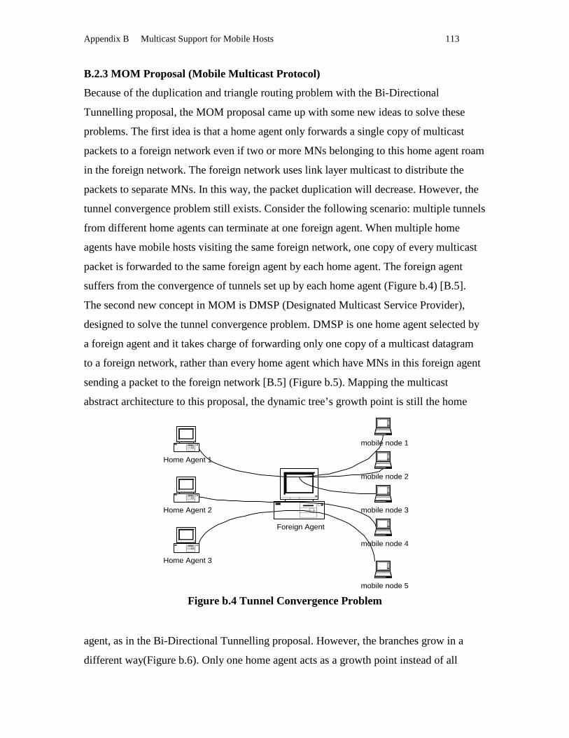
Appendix B Multicast Support for Mobile Hosts 113
B.2.3 MOM Proposal (Mobile Multicast Protocol)
Because of the duplication and triangle routing problem with the Bi-Directional
Tunnelling proposal, the MOM proposal came up with some new ideas to solve these
problems. The first idea is that a home agent only forwards a single copy of multicast
packets to a foreign network even if two or more MNs belonging to this home agent roam
in the foreign network. The foreign network uses link layer multicast to distribute the
packets to separate MNs. In this way, the packet duplication will decrease. However, the
tunnel convergence problem still exists. Consider the following scenario: multiple tunnels
from different home agents can terminate at one foreign agent. When multiple home
agents have mobile hosts visiting the same foreign network, one copy of every multicast
packet is forwarded to the same foreign agent by each home agent. The foreign agent
suffers from the convergence of tunnels set up by each home agent (Figure b.4) [B.5].
The second new concept in MOM is DMSP (Designated Multicast Service Provider),
designed to solve the tunnel convergence problem. DMSP is one home agent selected by
a foreign agent and it takes charge of forwarding only one copy of a multicast datagram
to a foreign network, rather than every home agent which have MNs in this foreign agent
sending a packet to the foreign network [B.5] (Figure b.5). Mapping the multicast
abstract architecture to this proposal, the dynamic tree’s growth point is still the home
agent, as in the Bi-Directional Tunnelling proposal. However, the branches grow in a
different way(Figure b.6). Only one home agent acts as a growth point instead of all
Figure b.4 Tunnel Convergence Problem
Home Agent 1
Home Agent 2
Home Agent 3
mobile node 1
mobile node 2
mobile node 3
mobile node 4
mobile node 5
Foreign Agent
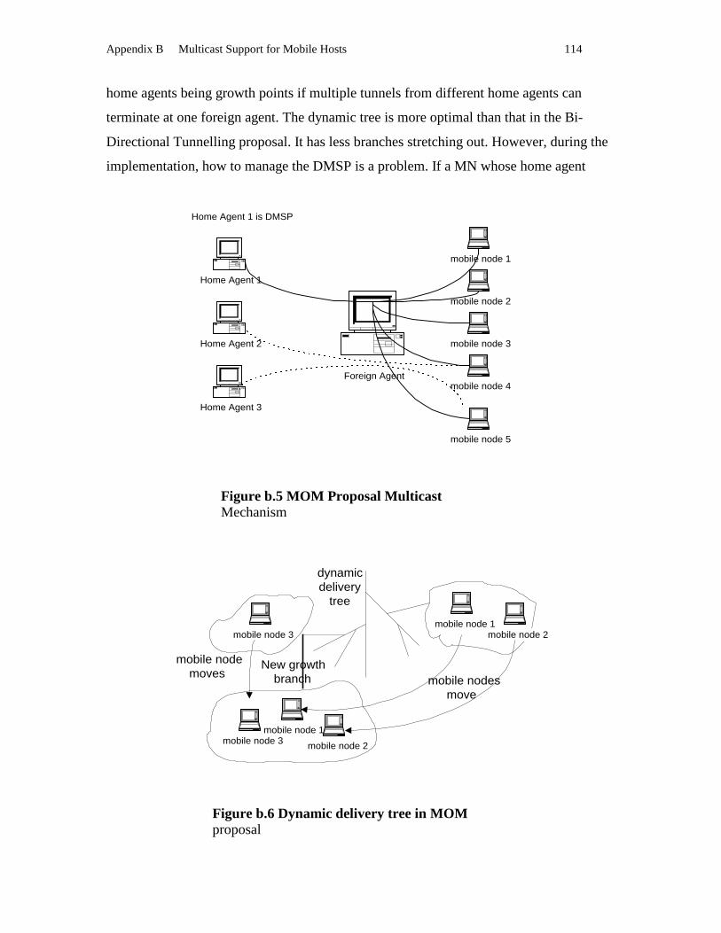
Appendix B Multicast Support for Mobile Hosts 114
home agents being growth points if multiple tunnels from different home agents can
terminate at one foreign agent. The dynamic tree is more optimal than that in the Bi-
Directional Tunnelling proposal. It has less branches stretching out. However, during the
implementation, how to manage the DMSP is a problem. If a MN whose home agent
Figure b.5 MOM Proposal Multicast Mechanism
mobile node 1
mobile node 1
dynamicdelivery
tree
New growthbranch mobile nodes
move
mobile node 2
mobile node 2
mobile node 3
mobile node 3
mobile nodemoves
Figure b.6 Dynamic delivery tree in MOM proposal
Home Agent 1
Home Agent 2
Home Agent 3
mobile node 1
mobile node 2
mobile node 3
mobile node 4
mobile node 5
Home Agent 1 is DMSP
Foreign Agent

Appendix B Multicast Support for Mobile Hosts 115
works as DMSP moves out of the foreign network, the foreign agent must select another
DMSP. The dynamic delivery tree will be modified according to the selection. How to
smooth hand-off the DMSP is the difficulty of MOM. The dynamic delivery tree is not
optimal yet because of the encapsulation and triangle unicast routing from home agent to
foreign agent. Especially, if the foreign network is near to the source or a branch of the
delivery tree, a home agent still needs to forward a multicast packet from far away.
B.2.4 MMA (Multicast by Multicast Agent) Proposal
Because the dynamic delivery tree is not optimal in the MOM proposal and the Bi-
Directional Tunneling proposal, researchers in Korea suggested MMA[B.4]. The MMA
approach uses a Multicast Agent (MA) that provides multicast services to mobile hosts. A
mobile host receives multicast traffic from the tunneling of a certain MA or directly from
the multicast router at the current network. Each MA has to support a certain group
service that has one Multicast Forwarder (MF) per group. A MF is one of the MAs that is
in charge of forwarding multicast data to other MAs. For each network, both the MF of
the MA and the MF of the mobile host, which resides in the same network, have an equal
MF value. Initially, if a MN wants to join a group in any foreign network, subscriptions
are done through the MA on the foreign network, which must be a multicast router. This
MA becomes a MF itself, and in this network mobile hosts receive multicast service
directly from the multicast router. Then, when the mobile host moves to another network,
the mobile host notifies the MA in the new network of its Group ID and its MF during
registration. The MF information of the MN is used by the MA in the new network as the
previous MF of the visiting MN. If the MA in the new network does not have a group
member, then it configures its own MF value with the previous MF of the MN.
Otherwise, if the new network has group members and an MF, at this time the MA
executes the MF selection algorithm and selects one of these two MFs: the current MF of
the MA or the MF of the visiting MN. Then both the MA and the MN replace their MF
value with the newly selected MF. There are two MF selection algorithms: the closest-
MF selection algorithm and the oldest-MF selection algorithm. According to the closest-
MF selection algorithm, the MF that is closer to the current MA is selected as a new MF.
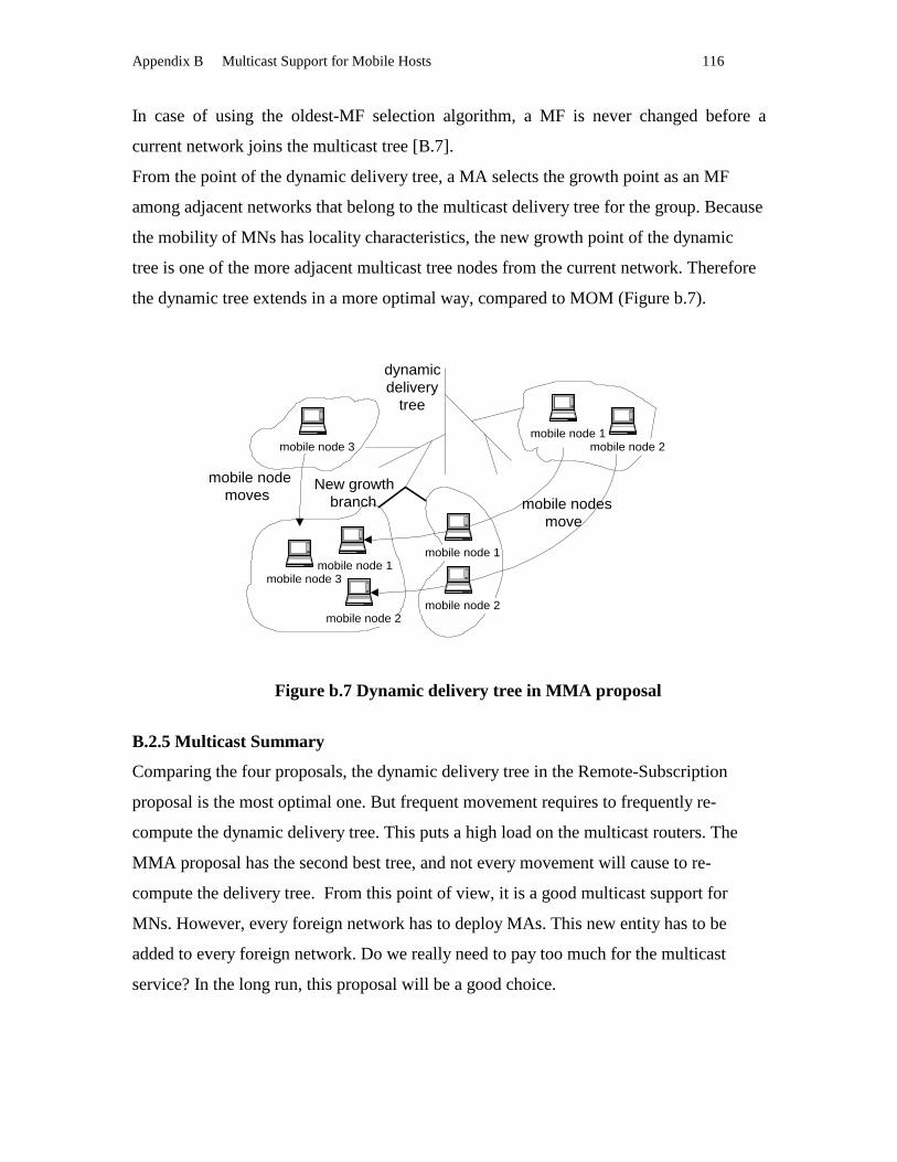
Appendix B Multicast Support for Mobile Hosts 116
In case of using the oldest-MF selection algorithm, a MF is never changed before a
current network joins the multicast tree [B.7].
From the point of the dynamic delivery tree, a MA selects the growth point as an MF
among adjacent networks that belong to the multicast delivery tree for the group. Because
the mobility of MNs has locality characteristics, the new growth point of the dynamic
tree is one of the more adjacent multicast tree nodes from the current network. Therefore
the dynamic tree extends in a more optimal way, compared to MOM (Figure b.7).
B.2.5 Multicast Summary
Comparing the four proposals, the dynamic delivery tree in the Remote-Subscription
proposal is the most optimal one. But frequent movement requires to frequently re-
compute the dynamic delivery tree. This puts a high load on the multicast routers. The
MMA proposal has the second best tree, and not every movement will cause to re-
compute the delivery tree. From this point of view, it is a good multicast support for
MNs. However, every foreign network has to deploy MAs. This new entity has to be
added to every foreign network. Do we really need to pay too much for the multicast
service? In the long run, this proposal will be a good choice.
mobile node 1
mobile node 1
dynamicdelivery
tree
New growthbranch mobile nodes
move
mobile node 2
mobile node 2
mobile node 3
mobile node 3
mobile nodemoves
mobile node 1
mobile node 2
Figure b.7 Dynamic delivery tree in MMA proposal
Appendix B Multicast Support for Mobile Hosts 117
B.3 Route Optimization in Multicast Suppor t for Mobile IP
The Bi-Directional Tunnelling and MOM rely on home agents as the dynamic delivery
tree’s growth points. They can only co-operate with base Mobile IP. In the Mobile IP
with Route Optimization, multicast packets still need to travel to HA first and are then
forwarded to MNs. For multicast packets, the triangle routing still exists in Mobile IP
with Route Optimization. The Remote-Subscription and MMA do not rely on home
agents as the dynamic delivery tree’s growth points. Mobile IP with Route Optimization
considers unicast packets only. In Remote-Subscription, the routing of multicast packets
is also optimal. In MMA, the routing of multicast packets is nearly optimal. Therefore, to
achieve Route Optimization for both unicast packets and multicast packets, we can
combine Remote-Subscription and Mobile IP with Route Optimization together by using
Mobile IP with Route Optimization to support unicast and using Remote-Subscription to
support multicast. We can combine MMA and Mobile IP with Route Optimization
together by using Mobile IP with Route Optimization to support unicast and using MMA
to support multicast. However, as we know, re-computing the dynamic delivery tree puts
a heavy workload on multicast router, we prefer to use MMA as multicast Route
Optimization and to use Mobile IP with Route Optimization as unicast Route
Optimization.
B.4 Secur ity in Multicast Suppor t for Mobile IP
For Bi-Directional Tunnelling Multicast, MNs and HAs share security keys. For Remote-
Subscription and MOM, MNs need to share a group membership security key with these
FAs. For MMA, MNs have to share a group membership security key with the new entity
MAs and MFs. For the multicast support, the security problem is that all group members
in a specific group share a common membership key. Wherever the MN roams, it can use
the membership key to identify itself as belonging to a specific multicast group. If there is
an access point to this specific multicast group, the MN can get multicast service by
identifying itself. However, the security level in multicast is lower than that in unicast
because most current multicast applications, such as weather broadcast etc, do not require
high security. Actually, mobility does not increase the security risk for multicast support
compared with current networks without MNs. No matter whether a node moves or not, it

Appendix B Multicast Support for Mobile Hosts 118
needs a membership key to join a specific multicast group. For multicast support, the
security problem in a static network and the security problem in a mobile network are the
same. Therefore, all these multicast proposals for Mobile IP do not discuss security and
the group membership key issues.
Appendix B Reference
[B.1] Charles E. Perkins, “Mobile IP Design Principles and Practices” , Addison Wesley,
1997, ISBN 0201634694
[B.2] Charles E. Perkins, “ IP Mobility Support for IPv4” RFC2002, October 1996
[B.3] William Stallings, “Operating Systems Internals and Design Principles” , Prentice-
Hall International, Inc, 1998
[B.4] John A. Selmys, “Linux – The New kid on the Block” ,
http://titanic.senecac.on.ca/comdex2000
[B.5] Tim G. Harrison, Carey L. Williamson, Wayne L. Mackrell, Richard B. Bunt,
“Mobile Multicast (MOM) Protocol: Multicast Support for Mobile Hosts” , MOBICOM
97 Budapest Hungary pp.151-160
[B.6] Alex C. Snoeren and Hari Balakrishnan, “An End-to-End Approach to Host
Mobility” , MOBICOM, 2000, Boston MA USA, pp.155-166
[B.7] HEE-SOOK, YOUNG-JOO SUH, “An Efficient Multicasting Protocol for Mobile
Hosts” , Proc. of the IASTED International Conference APPLIED INFORMATICS
February 14-17, 2000, Innsbruck, Austria, pp.60-66

Appendix C Basic Mobile IP Code Guide 119
Appendix C
Basic Mobile IP Code Guide
Figure C.1 Mobile IP Agent Control Flow in Basic Mobile IP Implementation
creating object: netmng* manager
the manager objectcommunicates with
Linux kernel bysocket() (Function:
read_sock)
agentdev_t object iscreated on receiving
signalRTM_NEWLINK from
kernel
ag_reg_t * reg andadver_t* ad is created
on receiving signalRTM_NEWADDRfrom Linux Kernel
setup Reg_sock andbind it to agent IPaddr,
put re_sock intoselect_object
socke_read:populating the mdb with
remote_mobile_t* object.if msg came from unknow mobile node
and call toremote_mobile_t::rcv_from_agent
or:remote_mobile_t::rcv_from_mobileor: local_mobile_t::rcv_from_agentor:local_mobile_t::rcv_from_mobile
(according to received ip address andmdb, acting as a foreign agent or a
home agent.)
setupsock (Ethernet raw
sock) and icmp_sock( icmp raw sock)
puting icmp_sock intoselect_obj to listen
solicitation frommobile nodes
putting sock intotimer_obj to advertise
the agentadvertisement msg to
mobile nodesperiodically

Appendix C Basic Mobile IP Code Guide 120
Figure C.2 Class Relationship of Mobile Agent in Basic Mobile IP Implementation
netmng_t
Data Member: device_cb_t watch_list; agentdev_t dev_list; ??? arp_list;
Member Function: read_sock(); find_agent(); parse_msg(); ... ...
Device_cb_t
Data Member:device_cb_fn fn;char * name;... ...
Member Function:key();compare_key();... ...
agentdev_t
Data Member: int index; ip32 ipaddr; char name[16]; char ethaddr; ag_reg_t *reg; advert_t *ad; ... ...
Member Function: ... ...
netdev_t
Data Member: netdev_t* next int index; ip32 ipaddr; char name[16]; char ethaddr[ETH_LEN]; ag_reg_t* reg; advert_t* ad; ... ...
advert_t
Data Member: ip32 local_addr; int sock; int icmp_sock;
... ...
Member Function: send_ad(); solicit_read(); ... ...
ag_reg_t
Data Member: ip32 ipaddr; int reg_sock; mobile_db_t mdb; netdev_t *dev; ... ...
Member Function: sock_read(); send_reply(); fwd_req(); fwd_reply(); ... ...
mdb (map)
IPaddr mobile_t*
134.117.57.160 local_mobile_t*
134.117.57.180 local_mobile_t*
134.117.57.204 local_mobile_t*
... ... ... ...
129.118.68.211 remote_mobile_t*
145.133.11.140 remote_mobile_t*
134.117.66.23 remote_mobile_t*
... ... ... ...
Initilizedfromread_configfile
Created bysock_readwhenreceivingfrom unknowmobile
has
has
has
inherent
has
include
Memeber Function: update_addr(); ... ...
mobile_t
Data Memeber: ip32 addr; ip32 coa; ip32 ha_addr; ip32 fa_addr; ag_reg_t * registra; event_t re_expire;
Member Function:bindto();unbind();
rcv_from_mobile()=0;rcv_from_agent()=0;
is populated from
remote_mobile_t local_mobile_t
Data Member:Member Function:
Data Member:Member Function:
inherent inherent

Appendix C Basic Mobile IP Code Guide 121
Figure C.3 Object Relationship of Mobile Agent in Basic Mobile IP Implementation
<<netmng>>manager
<<int>>rth_ifla.fd (rtnetlink socket)
<<netdev>>dev_list
<<netdev>>agentdev
<<advert_t>> ad
<<ag_reg_t>> reg
<<int>>icmp_sock
<<int>>reg_sock
<<int>>sock
<<mobile_db_t>>mdb
<<select_cb_t>>select_obj
<<timer_t>>timer_obj
socket_fd
reg_socket
sock
icmp_sock
... ...
read function
reg_sock_read()
read()
icmp_sock_read()
... ...
socket table
include(1..1)
include(1...1)
is composed of (1...*)
is a (1...1) is a (1..1)
include(1..1)
include(1..1)
include(1..1)
include(1..1)
are added into
include
is added into
is added into
is added into
Notice:1. <<name>> represents a class type 2. name under the class type represents anobject of the class type.

Appendix D Mobile IP with Route Optimization HOWTO 122
Appendix D
Mobile IP with Route Optimization HOWTO This appendix describes how to install and run the Mobile IP with Route Optimization. Step 1: Unzip the mipro2.tar.gz
$unzip mipro2.tar.gz $tar –xvf mipro2.tar
Step 2: Configure the system
By default the configuration file used is “ .mip” , which exists in /mipro2/agent, /mipro2/mobile and /mipro2/correspondent directory. The configuration file accepts the following statements: mobile { mobile ip addr} { agent ip addr} agent { agent ip addr} ignore { network interface} key { addr1} { addr2} { spi} { key} Here is a sample configuration file agent 134.117.66.21 eth0 mobile 134.117.57.204 134.117.57.101 ignore eth1 key 134.117.57.204 134.117.57.101 5 abcdef05abcdef05abcdef05abcdef05 key 134.117.67.140 134.117.57.101 4 abcdef04abcdef04abcdef04abcdef04 key 134.117.66.21 134.117.57.101 3 abcdef03abcdef03abcdef03abcdef03 key 134.117.57.204 134.117.66.21 2 abcdef02abcdef02abcdef02abcdef02 key 134.117.57.204 134.117.67.140 1 abcdef01abcdef01abcdef01abcdef01 key 134.117.66.21 134.117.67.140 6 abcdef06abcdef06abcdef06abcdef06
Step 3: Compile the code under mipro2 directory
1. Compile and link the source files except that under the subdirectory ./agent and ./correspondent $make
2. Compile and link the source files under the subdirectory ./agent and ./correspondent $cd ./agent $make $cd ../correspondent $make
Step 4: Modify Linux kernel source files 1. Copy modified sockios.h file to Linux kernel source file directory
$cp /mipro2/kernel/sockios.h /usr/src/linux/include/linux/ 2. Copy modified af_inet.c and ip_fw.c to Linux kernel source file directory
$cp /mipro2/kernel/af_inet.c /usr/src/linux/net/ipv4/
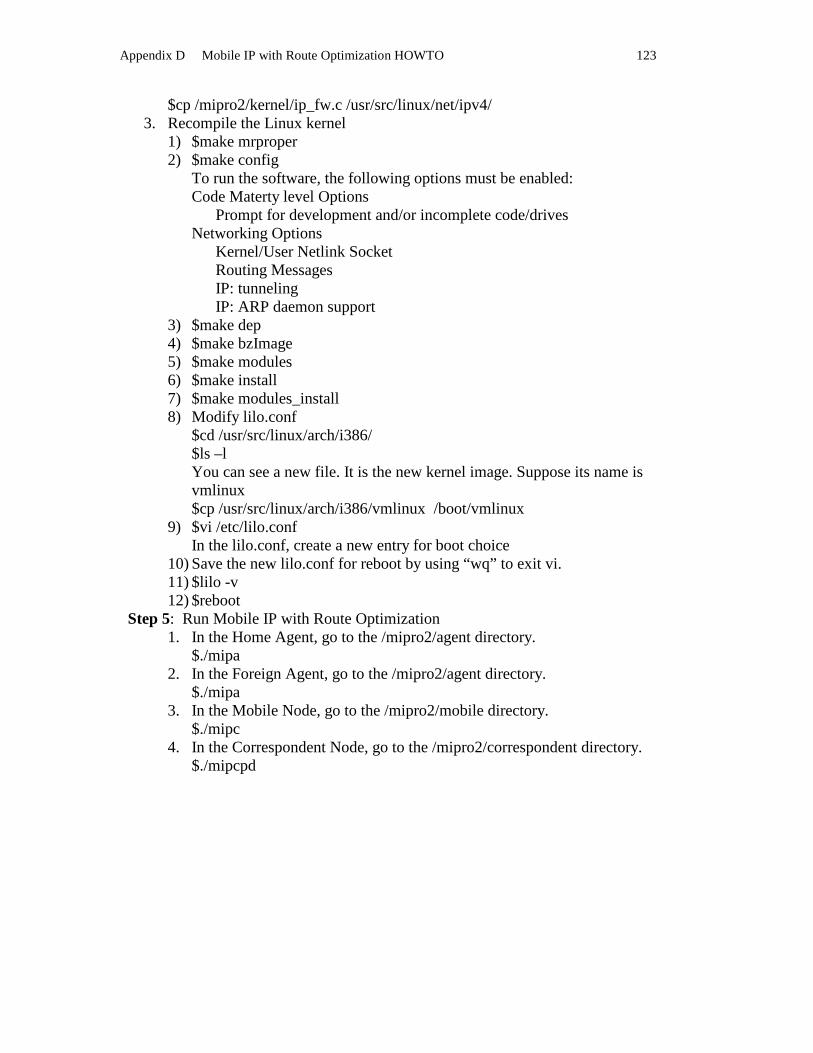
Appendix D Mobile IP with Route Optimization HOWTO 123
$cp /mipro2/kernel/ip_fw.c /usr/src/linux/net/ipv4/ 3. Recompile the Linux kernel
1) $make mrproper 2) $make config
To run the software, the following options must be enabled: Code Materty level Options Prompt for development and/or incomplete code/drives Networking Options Kernel/User Netlink Socket Routing Messages IP: tunneling IP: ARP daemon support
3) $make dep 4) $make bzImage 5) $make modules 6) $make install 7) $make modules_install 8) Modify lilo.conf $cd /usr/src/linux/arch/i386/ $ls –l
You can see a new file. It is the new kernel image. Suppose its name is vmlinux $cp /usr/src/linux/arch/i386/vmlinux /boot/vmlinux
9) $vi /etc/lilo.conf In the lilo.conf, create a new entry for boot choice
10) Save the new lilo.conf for reboot by using “wq” to exit vi. 11) $lilo -v 12) $reboot
Step 5: Run Mobile IP with Route Optimization 1. In the Home Agent, go to the /mipro2/agent directory.
$./mipa 2. In the Foreign Agent, go to the /mipro2/agent directory.
$./mipa 3. In the Mobile Node, go to the /mipro2/mobile directory.
$./mipc 4. In the Correspondent Node, go to the /mipro2/correspondent directory.
$./mipcpd