implementation guidelines for ansi/aiaa s-081; space...
TRANSCRIPT

SMC-TR-xx-xx AEROSPACE REPORT NO. TR-2001(8504)-1
Implementation Guidelines for ANSI/AIAA S-081; Space Systems-Composite Overwrapped Pressure Vessels
October 2001
Prepared by
J. B. CHANG Structural Mechanics Subdivision Vehicle Systems Division Engineering and Technology Group
Prepared for
SPACE AND MISSILE SYSTEMS CENTER AIR FORCE SPACE COMMAND 2430 E. El Segundo Boulevard Los Angeles Air Force Base, CA 90245
Contract No. F04701-00-C-009
Engineering and Technology Group
APPROVED FOR PUBLIC RELEASE; DISTRIBUTION UNLIMITED
.
Downloaded from http://www.everyspec.com
This report was submitted by The Aerospace Corporation, El Segundo, CA 90245-4691, under Contract No. F04701-01-C-0094 with the Space and Missile Systems Center, P. O. Box 92960, Los Angeles, CA 90009-2960. It was reviewed and approved for The Aerospace Corporation by Dr. Ernest R. Scheyhing, Principal Director. Dr. Louis C-P Huang was the project officer for the program. This report has been reviewed by the Public Affairs Office (PAS) and is releasable to the National Technical Information Service (NTIS). At NTIS, it will be available to the general public, including foreign nationals.
This technical report has been reviewed and is approved for publication. Publication of this report does not constitute Air Force approval of the report's findings or conclusions. It is published only for the exchange and stimulation of ideas. Dr. Louis C-P Huang SMA/AXZ
UC-0335/Chang
Downloaded from http://www.everyspec.com
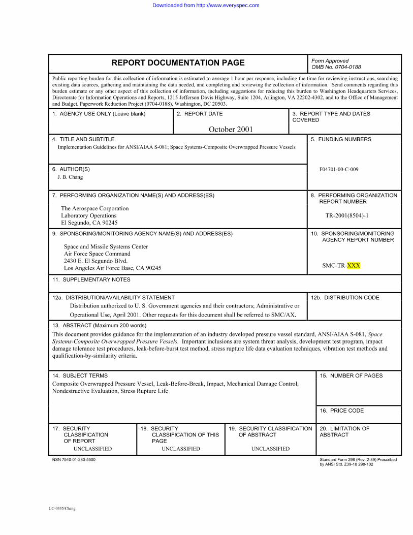
REPORT DOCUMENTATION PAGE Form Approved OMB No. 0704-0188
Public reporting burden for this collection of information is estimated to average 1 hour per response, including the time for reviewing instructions, searching existing data sources, gathering and maintaining the data needed, and completing and reviewing the collection of information. Send comments regarding this burden estimate or any other aspect of this collection of information, including suggestions for reducing this burden to Washington Headquarters Services, Directorate for Information Operations and Reports, 1215 Jefferson Davis Highway, Suite 1204, Arlington, VA 22202-4302, and to the Office of Management and Budget, Paperwork Reduction Project (0704-0188), Washington, DC 20503.
1. AGENCY USE ONLY (Leave blank) 2. REPORT DATE 3. REPORT TYPE AND DATES COVERED
October 2001 4. TITLE AND SUBTITLE 5. FUNDING NUMBERS
Implementation Guidelines for ANSI/AIAA S-081; Space Systems-Composite Overwrapped Pressure Vessels
6. AUTHOR(S) F04701-00-C-009 J. B. Chang
7. PERFORMING ORGANIZATION NAME(S) AND ADDRESS(ES) 8. PERFORMING ORGANIZATION REPORT NUMBER
The Aerospace Corporation Laboratory Operations El Segundo, CA 90245
TR-2001(8504)-1
9. SPONSORING/MONITORING AGENCY NAME(S) AND ADDRESS(ES) 10. SPONSORING/MONITORING AGENCY REPORT NUMBER
Space and Missile Systems Center Air Force Space Command 2430 E. El Segundo Blvd. Los Angeles Air Force Base, CA 90245
SMC-TR-XXX
11. SUPPLEMENTARY NOTES 12a. DISTRIBUTION/AVAILABILITY STATEMENT 12b. DISTRIBUTION CODE
Distribution authorized to U. S. Government agencies and their contractors; Administrative or Operational Use, April 2001. Other requests for this document shall be referred to SMC/AX.
13. ABSTRACT (Maximum 200 words) This document provides guidance for the implementation of an industry developed pressure vessel standard, ANSI/AIAA S-081, Space Systems-Composite Overwrapped Pressure Vessels. Important inclusions are system threat analysis, development test program, impact damage tolerance test procedures, leak-before-burst test method, stress rupture life data evaluation techniques, vibration test methods and qualification-by-similarity criteria.
14. SUBJECT TERMS 15. NUMBER OF PAGES Composite Overwrapped Pressure Vessel, Leak-Before-Break, Impact, Mechanical Damage Control, Nondestructive Evaluation, Stress Rupture Life
16. PRICE CODE
17. SECURITY
CLASSIFICATION OF REPORT
18. SECURITY CLASSIFICATION OF THIS PAGE
19. SECURITY CLASSIFICATION OF ABSTRACT
20. LIMITATION OF ABSTRACT
UNCLASSIFIED UNCLASSIFIED UNCLASSIFIED NSN 7540-01-280-5500 Standard Form 298 (Rev. 2-89) Prescribed
by ANSI Std. Z39-18 298-102
UC-0335/Chang
Downloaded from http://www.everyspec.com

Downloaded from http://www.everyspec.com

Foreword
This document was prepared as a part of the standard development activities funded by the Air Force/Space and Missile Systems Center (AF/SMC). John Ingram-Cotton of the System Engineering Directorate, Corporate Chief Architect/Engineer Office, is the Aerospace Program Manager. James B. Chang of Vehicle Systems Division, Engineering and Technology Group, is the Principal Investigator of this development effort.
Some of the guidelines presented in this document were provided by the members of the Aerospace Pressure Vessel Standard Working Group operated with the Structures Committee of the American Institute of Aeronautics and Astronautics (AIAA). Materials contained in the Appendices of this document are a part of the results generated from a research, development, test and evaluation (RDT&E) program led by Aerospace: Enhanced Technology for Composite Overwrapped Pressure Vessels. This RDT&E program was funded largely by AF/SMC. National Space and Aeronautics Administration (NASA) also funded a portion of the test activities performed at NASA/White Sands Test Facility (WSTF), New Mexico.
Downloaded from http://www.everyspec.com

Acknowledgements
The author would like to thank the AIAA Aerospace Pressure Vessel Standard Working Group members for providing valuable suggestions in the preparation of this guideline document. Special thanks go to Dr. Hank Babel and Ms. Lorie Grimes of Boeing Company, to Dr. Norman Newhouse of Lincoln Composites and to Ms. Lorie Grimes-Ledesma and Mr. Joseph Lewis of Jet Propulsion Laboratory, for their valuable inputs.
Downloaded from http://www.everyspec.com

Contents
1. Introduction ............................................................................................................................ 9
2. Scope ...................................................................................................................................... 11 2.1 General.......................................................................................................................... 11 2.2 Purpose ......................................................................................................................... 11 2.3 Organization of Handbook ........................................................................................... 11
4. Definitions, Abbreviations and Acronyms ............................................................................. 12
4.1 Definitions .................................................................................................................... 12 4.2 Abbreviations and Acronyms ....................................................................................... 15
5. Guidelines............................................................................................................................... 18 5.1 System Analysis ........................................................................................................... 18
5.1.1 Standard System Analysis Requirements ....................................................... 18 5.1.2 Guidance for System Analysis ....................................................................... 18
5.1.2.1 General Guidelines ........................................................................ 18 5.1.2.2 System Analysis Data.................................................................... 18 5.1.2.3 System Threat Analysis for COPVs .............................................. 19
5.2 Stress-Rupture Life....................................................................................................... 19 5.2.1 Standard Requirements................................................................................... 19 5.2.2 Guidance to Stress-Rupture Life Verification ................................................ 19
5.2.2.1 Design Curves ............................................................................... 19 5.2.2.2 Determination of Stress Rupture Life for Other Probability Values 19 5.4.2.3 New Materials................................................................................ 22
5.3 Damage Control............................................................................................................ 22 5.3.1 Standard Damage Control Requirements ....................................................... 22
4.2.10.1 Damage Control Plan..................................................................... 23 4.2.10.2 Approach A - Mechanical Damage Protection/Indication............. 23
4.2.10.2.1 Protective Covers...................................................... 23 4.2.10.2.2 Indicators .................................................................. 23
4.2.10.3 Approach B Damage Tolerance Demonstration............................ 23 5.3.2 Guidance for Damage Control........................................................................ 24
5.3.2.1 Overview of Impact-Damage Control Plan ................................... 24 5.4 Impact Damage Tolerance Demonstration ................................................................... 25
5.4.1 Standard Requirements........................................................................................................... 25 5.4.2 Guidance for Impact Damage Control.................................................................................... 25 5.5 Composite Material Strength Design Allowables .................................................................. 27
5.5.1 Standard Requirements................................................................................... 27 5.5.2 Guidance for Composite Material Allowable Generation .............................. 27
5.5.2.1 Composite Material Allowable Generated by Full-scale Specimens 27 5.5.2.2 Composite Materials Allowables Generated by Subscale Specimens 28
5.6 Non-destructive Inspections (NDI) Techniques ........................................................... 29 5.6.1 Standard Requirements................................................................................... 29 5.6.2 Guidance for NDI ........................................................................................... 29
Downloaded from http://www.everyspec.com

5.6.2.1 NDI Techniques for Metal Liners.................................................. 29 5.6.2.2 NDI Techniques for Composite Materials..................................... 30
5.7 Leak-Before-Burst Demonstration ............................................................................... 30 5.7.1 Standard Requirements................................................................................... 30 5.7.2 Guidance for LBB Demonstration.................................................................. 31
5.8 Acceptance Proof Testing............................................................................................. 32 5.8.1 Standard Requirements................................................................................... 32 5.8.2 Guidance for Acceptance Proof Testing......................................................... 32
5.8.2.1 Workmanship Screening................................................................ 32 5.8.2.2 Initial Flaw Size Determination..................................................... Error! Bookmark not de
5.9 Vibration/External Load Testing .................................................................................. 33 5.9.1 Standard Requirements................................................................................... 33 5.9.2 Guidance for Vibration/External Load Testing .............................................. 33
5.10 Leak Test ...................................................................................................................... 34 5.10.1 Standard Requirements................................................................................... 34 5.10.2 Guidance for Leak Test .................................................................................. 34
6. Specific Topics ....................................................................................................................... 35 6.1 Development Testing.................................................................................................... 36 6.2 Qualification by Similarity ........................................................................................... 36
Appendix A S-081 Requirements Appendix A A COPV Impact Damage Effects Assessment Study.................................................. 38 Appendix B COPV Impact Damage NDI Techniques Assessment ................................................. 9 Appendix C Proposed Impact Damage Control Plan....................................................................... 15
Downloaded from http://www.everyspec.com
Figures
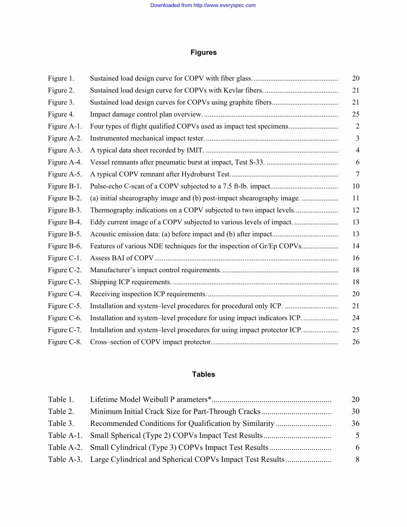
Figure 1. Sustained load design curve for COPV with fiber glass. .............................................. 20 Figure 2. Sustained load design curve for COPVs with Kevlar fibers. ........................................ 21 Figure 3. Sustained load design curves for COPVs using graphite fibers.................................... 21 Figure 4. Impact damage control plan overview. ......................................................................... 25 Figure A-1. Four types of flight qualified COPVs used as impact test specimens........................... 2 Figure A-2. Instrumented mechanical impact tester. ........................................................................ 3 Figure A-3. A typical data sheet recorded by IMIT. ........................................................................ 4 Figure A-4. Vessel remnants after pneumatic burst at impact, Test S-33. ....................................... 6 Figure A-5. A typical COPV remnant after Hydroburst Test........................................................... 7 Figure B-1. Pulse-echo C-scan of a COPV subjected to a 7.5 ft-lb. impact..................................... 10 Figure B-2. (a) initial shearography image and (b) post-impact shearography image. .................... 11 Figure B-3. Thermography indications on a COPV subjected to two impact levels........................ 12 Figure B-4. Eddy current image of a COPV subjected to various levels of impact. ........................ 13 Figure B-5. Acoustic emission data: (a) before impact and (b) after impact.................................... 13 Figure B-6. Features of various NDE techniques for the inspection of Gr/Ep COPVs.................... 14 Figure C-1. Assess BAI of COPV.................................................................................................... 16 Figure C-2. Manufacturer’s impact control requirements. ............................................................... 18 Figure C-3. Shipping ICP requirements. .......................................................................................... 18 Figure C-4. Receiving inspection ICP requirements. ....................................................................... 20 Figure C-5. Installation and system–level procedures for procedural only ICP. ............................. 21 Figure C-6. Installation and system–level procedure for using impact indicators ICP. ................... 24 Figure C-7. Installation and system–level procedures for using impact protector ICP.................... 25 Figure C-8. Cross–section of COPV impact protector. .................................................................... 26
Tables
Table 1. Lifetime Model Weibull P arameters*............................................................ 20 Table 2. Minimum Initial Crack Size for Part-Through Cracks ................................... 30 Table 3. Recommended Conditions for Qualification by Similarity ............................ 36 Table A-1. Small Spherical (Type 2) COPVs Impact Test Results .................................. 5 Table A-2. Small Cylindrical (Type 3) COPVs Impact Test Results ............................... 6 Table A-3. Large Cylindrical and Spherical COPVs Impact Test Results ....................... 8
Downloaded from http://www.everyspec.com

Downloaded from http://www.everyspec.com

1. Introduction
Pressure vessels, such as helium gas bottles and hydrazine propellant tanks, are some of the most safety-critical components used in space systems. Any pressure vessel that contains compressed gas constitutes a potential hazard because of the risk of inadvertent release of the stored energy. If a highly pressurized vessel bursts, the stored energy can be converted to a destructive blast wave that can destroy surrounding structures or cause severe injuries or fatalities to the personnel working around it. A leaking liquid propellant storage tank is equally dangerous, because many propellants present toxicity hazards to ground personnel during handling and installation. Furthermore, a leaking helium pressure bottle may jeopardize the planned mission of any space system.
Most pressure vessels used in earlier space systems were made of high strength metals such as steel, titanium, and Inconel alloys. In the 1970s, all space flight metallic pressure vessels (MPVs) used in military space systems were designed, analyzed, and qualified per MIL-STD-1522 (Ref. 1). In 1984, MIL-STD-1522 was revised to include safe-life demonstration requirements for MPVs that contain hazardous fluids or exhibit leak-before-burst (LBB) failure mode. The revised version was identified as MIL-STD-1522A (Ref. 2) and was the most popular pressure vessel standard used in the space industry on military, civil, domestic, and foreign space programs in the last two decades. However, there are a few important areas that were not covered in MIL-STD-1522A. The major ones include: no detailed requirements for composite materials used in composite overwrapped pressure vessels (COPVs); no specific requirements for metallic pressurized structures such as the main propellant tanks of a launch vehicle; and no distinction for special pressure equipment including batteries, heat pipes, sealed containers, and cryostats. (Ref. 3).
In 1993, Aerospace was tasked by Air Force (AF)/Space and Missile Systems Center (SMC) to update MIL-STD-1522A to include specific requirements in those areas. However, due to the military acquisition reform, SMC decided to cancel most of the military standards and specifications and discontinue the update activity. Recognizing the need to have industry uniformed standards, in 1996, American Institute of Aeronautics and Astronautics (AIAA) formed the Aerospace Pressure Vessel Standard Working Group to take over the standard development activities for pressure vessels and related hardware items. All standards developed by this group are to be approved by American National Standard Institute (ANSI) as American national standards. The first standard developed by this working group was ANSI/AIAA S-080 (Ref. 4) which contains the requirements for MPVs and other metallic pressurized hardware items. Specific requirements for metallic pressurized structures, battery cases, heat pipes etc. are contained in this standard. The second standard developed by this working group was the COPV standard, ANSI/AIAA S-081 (Ref. 5).
COPVs are fabricated by overwrapping thin metal liners with composite materials such as graphite/epoxy (Gr/Ep). High pressure helium tanks used in the Integrated Apogee Boost System (IABS) of Defensse Satellite Communications Systems (DSCS) and Ultra High Frequency/Follow-On (UHF/FO) Satellite are all Gr/Ep COPVs. Gr/Ep composite materials are being widely used for fabricating aircraft structures including wings and tails; and launch vehicle structures such as solid rocket motor cases and fairings. This is because Gr/Ep has high specific strength and modulus. However, Gr/Ep composites are known to be susceptible to impact damage. Damage tolerance control requirements have been imposed on critical-to-flight composite aircraft structures (Ref. 6). However, requirements established for aircraft structures can not directly applied to COPVs due to their sizes and loading conditions.
In order to assess the need for impact damage control and other requirements on space flight COPVs, SMC sponsored a research, development, test and evaluation (RDT&E) program, “Enhanced Technology for Composite Overwrapped Pressure Vessels” in 1995 (Ref. 7). Impact damage effects study on COPVs
Downloaded from http://www.everyspec.com
was the major task of this RDT&E effort. Test results conducted in this program showed that thin-wall COPVs (wall thickness less than 0.25 in.) are indeed vulnerable to impact. At impact damage energy levels even less than the COPV’s visible damage threshold (VDT), the residual strength, or burst strength after impact (BAI), for one batch of flight qualified light-weight cylindrical COPV (with 0.15 in. wall thickness) has showed up to 30 percent reduction. One such COPV that was fully charged with helium gas exploded on test stand, 0.7 sec. after impact (Ref. 8).
The findings from the impact damage effects study have motivated to introduce a new set of impact damage control requirements for thin-walled light-weight COPVs in S-081. In addition to impact damage control requirements, it contains many new requirements including the leak-before-burst (LBB) and safe-life test requirements for elastic-plastic liner, strength allowables and stress-rupture data generation requirements for composite materials used for composite materials. The complete set of requirements are shown in Appendix A. S-081 is a top-level requirement document. It only specifies “what-to-do” but not “how-to-do.” Since impact damage control requirements and other requirements are new to many COPV users, it is prudent to have a “how-to-do” document that provides guidelines to the users for their implementation of S-081. This report was prepared for that purpose. In addition to the proposed impact damage tolerance control procedures, other important inclusions such as guidelines for system threat analysis, development test procedures, leak-before-burst demonstrations, vibration test methods, and qualification by similarity criteria are also provided in this guideline documents.
Downloaded from http://www.everyspec.com

2. Scope
2.1 General This document provides additional information pertaining to the requirements of ANSI/AIAA S-081-2000 “Space Systems-Composite Overwrapped Pressure Vessels.”
2.2 Purpose This document was prepared to provide explanations and guidance to the users of S-081. The information presented herein is intended to aid in the formulation and review of detailed analysis and test requirements for composite overwrapped pressure vessels (COPVs) used in the space systems.
2.3 Organization of Guidelines Document The organization of this document differs from that in S-081 where requirements for each technical area such as strength, fatigue-life, safe-life, material selection, and evaluation are individually specified. In this document, only those technical areas that are judged to be relatively new to the users are included in the guidelines sections. The exact requirements specified in S-081 are repeated in this document shown in italic.
Downloaded from http://www.everyspec.com

3. Definitions, Abbreviations and Acronyms
3.1 Definitions The following definitions of significant terms are provided to ensure precision of meaning and consistency of usage in this handbook.
“A” Basis Allowable: The mechanical strength values such that at least 99% of the population will meet or exceed the specified values with a 95% confidence level.
Acceptance Test: The required formal test conducted on the flight hardware to ascertain that the materials, manufacturing processes, and workmanship meet specifications and that the hardware is acceptable for its intended usage.
Allowable Load (Stress): The maximum load (stress) that can be accommodated by a structure (material) without rupture, collapse, or detrimental deformation in a given environment. Allowable stresses are commonly the statistically based ultimate strength, buckling strength, and yield strength, respectively.
Applied Load (Stress): The actual load (stress) imposed on the structure in the service environment.
Autofrettage: An operation for a composite overwrapped pressure vessel (COPV) containing metal liner where pressure driving deformation is used to plastically yield the metal liner into the composite overwrap in order to induce compressive stress states in the metal liner. This operation is often referred as sizing.
"B" Basis Allowable: The mechanical strength values such that at least 90% of the population will meet or exceed the specified values with a 95% confidence level.
Brittle Fracture: A type of catastrophic failure mode in structural materials that usually occurs without prior plastic deformation and at extremely high speed. The fracture is usually characterized by a flat fracture surface with little or no shear lips (slant fracture surface) and at average stress levels below those of general yielding.
Burst Pressure: The pressure level at which rupture or unstable fracture of the pressurized hardware actually occurs.
Composite Overwrapped Pressure Vessel (COPV): A pressure vessel built by using fiber-based composite materials overwrapping a thin metallic or plastic liner. The liner serves as a barrier which may or may not carry substantive pressure loads. The composite overwrap always carries pressure loads. In this handbook, the term applies only to the overwrapped vessels with metallic liners.
Critical Condition: The most severe environmental condition in terms of loads, pressures, and temperatures, or combinations thereof, imposed on systems, subsystems, and components during service life.
Critical Flaw: A specific shape of a flaw or a crack-like defect existing in the metallic hardware or in the metallic liner of a COPV with sufficient size that unstable growth will occur under the specific operating load and environment.
Critical Stress Intensity Factor: The value of the stress intensity factor at which unstable fracture occurs.
Damage Tolerance: The ability of the structure to sustain a level of damage or presence of a defect and yet be able to perform its operational functions.
Downloaded from http://www.everyspec.com

Design Burst Factor (DBF): A multiplying factor to be applied to maximum expected operating pressure (MEOP) to obtain design burst pressure for the purposes of analytical assessment and/or test verification of the strength adequacy of pressurized hardware design. DBF is often referred as the burst factor (BF).
Design Burst Pressure: A pressure level that pressurized hardware must withstand without rupture in the applicable operating environment. It is equal to DBF x MEOP
Design Safety Factor: A factor used to account for uncertainties in material properties and analysis procedures. Design safety factor is often called design factor of safety, or, simply, factor of safety.
Destabilizing Pressure: A pressure that produces compressive stresses in the pressurized hardware.
Detrimental Deformation: The structural deformation deflection or displacement that prevents any portion of the structure from performing its intended function, or that reduces the probability of successful completion of the mission.
Development Test: A test conducted to provide design information that may be used to check the validity of analytic techniques and assumed design parameters; uncover unexpected system response characteristics; evaluate design changes; determine interface compatibility; prove qualification and acceptance procedures and techniques; as well as establish accept/reject criteria for nondestructive inspection (NDI).
Ductile Fracture: A type of failure mode in metallic materials generally preceded by a large amount of plastic deformation and in which the fracture surface is inclined to the direction of the applied stress.
Embrittlement Mechanism: A failure process that results from the interaction of environments with metals, usually in combination with applied or residual tensile stresses. The most common type of such failure process is hydrogen embrittlement, caused by an initial presence or absorption of excessive amounts of hydrogen in metals.
Fatigue: The process of progressive localized permanent structural change occurring in a material subjected to conditions which produce fluctuating stresses and strains at some point or points and which may culminate in cracks or complete fracture after a sufficient number of fluctuations.
Fatigue-Life: The number of cycles of applied external load and/or pressurization that the unflawed pressurized hardware can sustain before failure of a specified nature could occur.
Flaw: A local discontinuity in a structural material, such as a scratch, notch, crack, or void.
Flaw Shape (a/2c or a/c): The shape of a surface flaw or a corner flaw where “a” is the depth, “2c” is the length of the surface flaw and “c” is the length of the corner flaw.
Fracture Control: The application of design philosophy, analysis method, manufacturing technology, quality assurance, and operating procedures to prevent premature structural failure due to the propagation of cracks or crack-like defects during fabrication, testing, transportation and handling, and service.
Fracture Mechanics: An engineering discipline that describes the behavior of cracks or crack-like defects in materials under stresses.
Fracture Toughness: A generic term used for the measurements of the resistance to extension of a crack in metallic materials.
Impact Damage: Mechanical damage which is caused when an object strikes on a hardware item or the hardware item strikes an object.
Impact-Damage Control: A procedure and process that address the prevention and protection of a COPV from damage due to the potential impact event in the manufacturing, testing, transportation, ground handling, storage, assembly, and service stages.
Downloaded from http://www.everyspec.com
Initial Flaw: A flaw or a crack-like defect in a structural material before the application of load and/or deleterious environment.
Leak-Before-Burst (LBB): A phenomenon as well as a design approach in which any pre-existing flaw will grow through the wall of a COPV at or below MEOP and result in pressure-relieving leakage, rather than rupture (catastrophic failure).
Limit Load: The maximum expected external load or combination of loads which a pressure vessel or a pressurized structure may experience during the performance of specified missions in specified environments. When a statistical estimate is applicable, the limit load is that load not expected to be exceeded at 99% probability with 95% confidence. The correspondence stress is called limit stress.
Loading Spectrum: A representation of the cumulative loading anticipated for the structure under all expected operating environments. Significant transportation and handling loads are included.
Margin of Safety (MS):
MS=[Allowable Load/Limit Load x DSF] -1 Note: Load may mean stress or strain
Maximum Design Pressure (MDP): The highest pressure defined by maximum relief pressure, maximum regulator pressure, or maximum temperature. Transient pressures shall be considered. Where pressure regulators, relief devices, and/or thermal control (e.g., heaters) are used to control pressure, collectively they must be two-fault tolerant from causing the pressure to exceed the MDP or the system.
Maximum Expected Operating Pressure (MEOP): The maximum pressure the pressurized hardware is expected to experience during its service life, in association with its applicable operating environments.
Plastically Responding Metallic Liner: A metallic liner of a COPV that experiences plastic response when pressurized to pressures up to and including proof pressure.
Proof Factor: A multiplying factor applied to the limit load and/or MEOP to obtain proof load and/ or proof pressure for use in the acceptance testing.
Proof Pressure: The proof pressure is used to give evidence of satisfactory workmanship and material quality and/or establish maximum initial flaw sizes for safe-life demonstration. It is equal to the product of MEOP and a proof factor.
Qualification Tests: The required formal contractual tests used to demonstrate that the design, manufacturing, and assembly have resulted in hardware designs conforming to specification requirements.
Residual Strength: The maximum value of load (stress) that cracked or damaged hardware is capable of sustaining without unstable crack growth.
Residual Stress: The stress that remains in a structure after processing, fabrication, assembly, testing, or operation. A typical example is the welding induced residual stress.
Safe-Life: The required cycles and period during which a structure, containing the largest undetected crack, is shown by analysis or testing not to fail catastrophically in the expected service load and environment.
Service-Life: The period of time (or cycles) that starts with the manufacturing of the pressure vessel and continues through all acceptance testing, handling, storage, transportation, launch operations, orbital operations, reentry or recovery from orbit, refurbishment, retesting and reuse that may be required or specified for the item.
Downloaded from http://www.everyspec.com

Stress-Corrosion Cracking: A mechanical-environmental induced failure process in which, sustained tensile stress and chemical attack combine to initiate and propagate a crack or a crack-like flaw in a metal part.
Stress Intensity Factor (K): A parameter that characterizes the stress-strain behavior at the tip of a crack contained in a linear elastic, homogeneous, and isotropic body.
Stress-Rupture Life: The minimum time during which the composite maintains structural integrity during the required service life considering the combined effects of stress level(s), time at stress level(s), and associated temperature and moisture.
Ultimate Load: The product of the limit load and the ultimate design safety factor.
Visual-Damage Threshold: (VDT): An impact energy level shown by test(s) that creates an indication which is barely detectable using an unaided visual technique.
3.2 Abbreviations and Acronyms AE = Acoustic Emission AIAA = American Institute of Aeronautics and Astronautics ANSI = American National Standard Institute ASME = American Society for Mechanical Engineering BAI = Burst Strength After Impact COPV = Composite Overwrapped Pressure Vessel DBF = Design Burst Factor DSF = Design Safety Factor Ftu = Ultimate Tensile Strength Gr/Ep = Graphite/Epoxy Hz = Hertz ICP = Impact Control Plan IDP = Impact Damage Threshold IMIT = Instrumented Mechanical Impact Tester K = Stress Intensity Factor Kc = Fracture Toughness LBB = Leak-Before-Burst LEFM = Linear Elastic Fracture Mechanics MCPT = Multiple-Cycle Proof Test MDP = Maximum Design Pressure MEOP = Maximum Expected Operating Pressure MIL-HDBK = Military Handbook MIL-STD = Military Standard MS = Margin of Safety NASA = National Aeronautics and Space Administration NDE = Nondestructive Examination NDI = Nondestructive Inspection POD = Probability of Detection PV = Pressure Vessel PS = Pressurized Structures QA = Quality Assurance RTD&E = Research, Development, Test & Evaluation SCC = Standard Cubic Centimeter Sec = Second
Downloaded from http://www.everyspec.com

USAF/SMC = United States Air Force/ Space and Missile Systems Center VDT = Visual Damage Threshold
Downloaded from http://www.everyspec.com

Downloaded from http://www.everyspec.com

4. S-081 Requirements and Corresponding Guidelines
This section provides the guidelines for the implementation of S-081 requirements in the technical areas that are relatively new to the users. Contents of those requirements are presented in the specific section for information purpose. The requirements are printed in italic. For completeness, all the requirements specified in S-081 are shown in Appendix A.
4.1 System Analysis
4.1.1 Standard System Analysis Requirements A system analysis shall be performed per the applicable requirements of Section 4.1 of ANSI/AIAA S-080 to establish design and performance requirements for the COPV.
4.1.2 Guidance for System Analysis
4.1.2.1 General Guidelines It is usually the responsibility of the primary contractor (or procuring agency) of the space system in which the pressure vessel will be used to perform detailed system analysis. In addition to establishing the correct maximum expected operating pressure (MEOP), the system analysis is to determine that the operation, interaction, or sequencing of components will not lead to damage to the space system, or associated ground support equipment. The analysis should identify any single malfunction or personnel error in operation of any component that will create conditions leading to an unacceptable risk to operating personnel or equipment. The analysis should also evaluate any secondary or subsequent occurrence, failure, or component malfunction which, initiated by a primary failure, could result in personnel injury. Such items identified by the analysis should be designated safety critical and will require the following considerations.
a) Specific design action b) Special safety operating requirements c) Specific hazard identification and proposed corrective action or control d) Special safety supervision
4.1.2.2 System Analysis Data Systems analysis data should show that:
a) The system provides the capability of maintaining all pressure levels in a safe condition in the event of interruption of any process or control sequence at any time during test or countdown.
b) Redundant pressure relief devices, if required, should have mutually independent pressure escape routes.
c) In systems where pressure regulator failure may involve critical hazard to the crew or mission success, regulation should be redundant. Where passive redundant systems are specified, it should include an automatic switch-over.
d) When the hazardous effects of safety critical failures or malfunctions are prevented through the use of redundant components or systems, it should be mandatory that all such redundant
Downloaded from http://www.everyspec.com
components or systems are operational prior to the initiation of irreversible portions of safety critical operations or events.
4.1.2.3 System Threat Analysis for COPVs For COPVs, a system level threat analysis should be performed. The potential sources of impact, and the impact energy levels during system integration should be identified. The pressure level of the COPV at each potential source of impact should also be established. Potential damage events include but are not limited to: COPV drops onto surfaces, COPV rotation on surfaces, torque wrench slips, tool impacts or scuffs/gouges on the outer surface of the COPV, forklift impacts, crane-hook impacts.
4.2 Stress-Rupture Life
4.2.1 Standard Requirements The COPV shall be designed to meet the design life considering the time it is under sustained load. There shall be no credible stress rupture failure modes based on stress rupture data for a probability of survival of 0.999.
To meet the stress rupture requirements, the lowest fiber reinforcement stress ratio at MEOP shall be:
Carbon = 1.5
Aramid = 1.65
Glass = 2.25
Other materials shall have stress rupture data and reliability analysis comparable to the materials listed above to support a given stress ratio at MEOP.
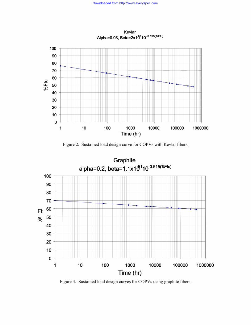
4.2.2 Guidance to Stress-Rupture Life Verification Verification that a COPV will survive the time it is at pressure should be determined from the analysis methods and material database provided in this section for three major classes of yarns that have been characterized:
Pan-based, intermediate modulus graphite yarns; Kevlar 49; E or S glass.
4.2.2.1 Design Curves Curves are given in Figures 1 through 3 (Ref. 9) for determining the allowable sustained load operating stress for a specified time at load using a probability of survival of 0.999. The time at pressure represents the sum of the time that the COPV is pressurized at or above 60% of MEOP.
4.2.2.2 Determination of Stress Rupture Life for Other Probability Values For a probability of survival value higher than 0.999, new curves can be created through use of the two-parameter Weibull distribution equation below.
Downloaded from http://www.everyspec.com

α
β
−
=t
etP )(
where P(t) = probability of failure for a specified value of time (design life)
t = time in hours α = Weibull shape factor β = Weibull beta (characteristic life)
The values of α and β can be determined from the equations in Table 1. The equations can then be manipulated for various probabilities of survival values and plotted like Figures 1-3.
0
10
20
30
40
50
60
70
80
90
100
1 10 100 1000 10000 100000 1000000
%Ft
u
GlassAlpha=1, Beta=1.4x101310 -0.159(%Ftu)
GlassAlpha=1, Beta=1.4x101310 -0.159(%Ftu)1310 -0.159(%Ftu)
0
10
20
30
40
50
60
70
80
90
100
1 10 100 1000 10000 100000 1000000Time (hr)
%Ft
u
0
10
20
30
40
50
60
70
80
90
100
1 10 100 1000 10000 100000 1000000
%Ft
u
GlassAlpha=1, Beta=1.4x101310 -0.159(%Ftu)
GlassAlpha=1, Beta=1.4x101310 -0.159(%Ftu)1310 -0.159(%Ftu)
GlassAlpha=1, Beta=1.4x101310 -0.159(%Ftu)
GlassAlpha=1, Beta=1.4x10
GlassAlpha=1, Beta=1.4x101310 -0.159(%Ftu)1310 -0.159(%Ftu)
GlassAlpha=1, Beta=1.4x101310 -0.159(%Ftu)1310 -0.159(%Ftu)
0
10
20
30
40
50
60
70
80
90
100
1 10 100 1000 10000 100000 1000000Time (hr)
%Ft
u
Figure 1. Sustained load design curve for COPV with fiber glass.
Table 1. Lifetime Model Weibull P arameters*
Composite System Shape Parameter Scale Parameters
Glass/epoxy Alpha = 1.00 Beta = (1.4 x 10¹³)10[-0.158(%ULT]a Kevlar/epoxy Alpha = 0.93 Beta = (2.0 x 10¹⁸)10[-0.198(%ULT] Graphite/epoxy Alpha = 0.20 Beta = (1.4 x 1051)10[-0.515%ULT]
a %ULT is the applied stress level as a percentage of the ultimate burst strength (e.g., for applied stress level of 50% ultimate burst strength, %ULT = 50)
Downloaded from http://www.everyspec.com
KevlarAlpha=0.93, Beta=2x101810 -0.198(%Ftu)
0
10
20
30
40
50
60
70
80
90
100
1 10 100 1000 10000 100000 1000000Time (hr)
%Ft
u
KevlarAlpha=0.93, Beta=2x101810 -0.198(%Ftu) Alpha=0.93, Beta=2x101810 -0.198(%Ftu) 1810 -0.198(%Ftu)
0
10
20
30
40
50
60
70
80
90
100
1 10 100 1000 10000 100000 1000000Time (hr)
%Ft
u
Figure 2. Sustained load design curve for COPVs with Kevlar fibers.
Graphitealpha=0.2, beta=1.1x105110-0.515(%Ftu)
0
10
20
30
40
50
60
70
80
90
100
1 10 100 1000 10000 100000 1000000
Time (hr)
%Ftu
Graphitealpha=0.2, beta=1.1x105110-0.515(%Ftu)alpha=0.2, beta=1.1x105110-0.515(%Ftu)5110-0.515(%Ftu)
0
10
20
30
40
50
60
70
80
90
100
1 10 100 1000 10000 100000 1000000
Time (hr)
%Ftu
Figure 3. Sustained load design curves for COPVs using graphite fibers.
Downloaded from http://www.everyspec.com
4.4.2.3 New Materials New materials will require determination of stress rupture behavior. Although long term pressure testing of COPVs would be preferable, strand tests provide a conservative guideline for determination of stress rupture behavior. A general approach for creating design curves from COPV data is outlined below.
In order to create a stress rupture curve, data from COPV tests of a minimum of two load levels should be available. No fewer than three samples should be available at each load level (note: if more data exists, results will be less conservative if more samples are used).
1. For each load level, the Weibull parameters from the equation in section 4.5.2 should be determined. In order to determine the parameters, the procedure below can be followed:
a) A set of data must be gathered that contains times to failure of different COPVs for several stress levels. Data at each stress level must then be tabulated in increasing order and ranked (using a median rank table).
b) After ranking the data, the data at each stress level is plotted individually on Weibull paper as a function of rank. A best-fit line is drawn through the data (visually, or using a fitting technique like linear regression). Alpha and beta values for each stress level are determined directly from the chart.
c) Once charts are created for each stress level, the beta values are plotted as a function of stress level. A semi-log plot of scale parameter vs. %FTU should be used to provide a linear function. An equation for the function is determined and used to determine the beta value for the system (see those in Table 1). To determine the system shape parameter, the lowest alpha value should be chosen for use.
2. Use the Weibull equation provided above to generate a lifetime curve. Curves should be plotted on a lognormal scale.
4.3 Damage Control
4.3.1 Standard Damage Control Requirements COPVs with a burst factor of 4.0 or greater and a total wall thickness of 0.25 inch or greater are exempted from the requirements of Section 4.2.10 (in S-081).
Mechanical damage that may degrade the performance of the COPV below the minimum strength requirements of Section 4.2.2(in S-081) shall be prevented. A damage control plan in accordance with Section 4.2.10.1 (in S-081) is mandatory.
For mechanical damage mitigation, a minimum of one of the following approaches shall be adapted:
(a) Mechanical Damage Protection/Indication
(b) Damage Tolerance Demonstration
These two approaches are described below.
A mechanically damaged COPV requires procurement agency Material Review Board (MRB) approval prior to use.
Downloaded from http://www.everyspec.com

Damage Control Plan The damage control plan shall document the threat analysis and procedures which mitigate these threats. The threat analysis shall document the conditions (source and magnitude of threat and state of pressurization of the COPV) under which mechanical damage can occur. The Damage Control Plan shall delineate all potentially damaging events and investigate mitigating procedures from the point of time when the COPV reinforcing matrix is cured to the end of service life.
Approach A - Mechanical Damage Protection/Indication Protective covers shall provide isolation from a mechanical damage event. Protective covers shall be used when the COPV has not demonstrated sufficient strength per Section 4.2.2 after a mechanical damage incident that is consistent with the worst case credible threat identified in Section 4.2.10.1. The following requirements shall apply for protective covers and /or indicators:
Protective Covers The effectiveness of protector covers shall be demonstrated by test
Protective covers or standoffs which isolate the vessel are required when personnel will be exposed to pressurized COPVs having stored energy levels in excess of 14,240 ft-lbf (19, 310 joules) or containing hazardous fluids. They shall be designed to completely protect the COPV under the worst credible threat defined in Section 4.2.10.1. They shall allow transmission of less than 5 ft-lbf (6.8 joules) of energy or reduce the transmitted energy to a level not to exceed one half that demonstrated as acceptable by pressurized damage tolerance or residual strength testing.
Protective covers shall not be removed until the latest practical time prior to launch or during other critical operations requiring cover removal.
Indicators When protective covers are not used, or the indicators are placed between the protective cover and the COPV, the effectiveness of the indicators to provide positive evidence of a mechanical damage event less than or equal to the demonstrated residual strength capability of the unprotected COPV shall be demonstrated by test. If residual strength testing of the COPV is not performed, the indicators shall be capable of detecting a 5 ft-lbf (6.8 joule) impact with a 0.5 in. (13-mm) diameter steel hemispherical tup impactor.
When indicators are placed outside of the protective cover, the effectiveness of the indicator to provide a positive evidence of impact in excess of the cover isolation capability shall be demonstrated by test.
The use of indicators as the sole means of mitigating threats for pressurized COPVs, as defined in Section 4.2.10.1, (in S-081) during personnel workaround is prohibited.
Approach B Damage Tolerance Demonstration Mechanical damage tolerance demonstration is an alternative to, or complementary with, mechanical damage covers to satisfy the requirements for damage control
Downloaded from http://www.everyspec.com

4.3.2 Guidance for Damage Control
COPVs are known to be susceptible to damage resulting from handling, tool drop impacts, or impacts from other objects. The visual damage threshold (VDT) energy level for many COPVs is equal to or lower than the impact damage threshold (IDT) energy level required to degrade the burst-strength after impact (BAI) below the specified design burst pressure of the vessel. Thus, impact-damage control is required throughout all stages of the COPV handling and service life. The purpose of the impact-damage control for a COPV is to establish procedures that:
1) Prevent impact damage to COPVs during manufacturing, shipping, handling, installation, and system-level operations;
2) Define methods for detecting, evaluating, and dispositioning potential impact damage incidents; and
3) Identify the approach for assessing the burst strength of a COPV following an impact damage incident.
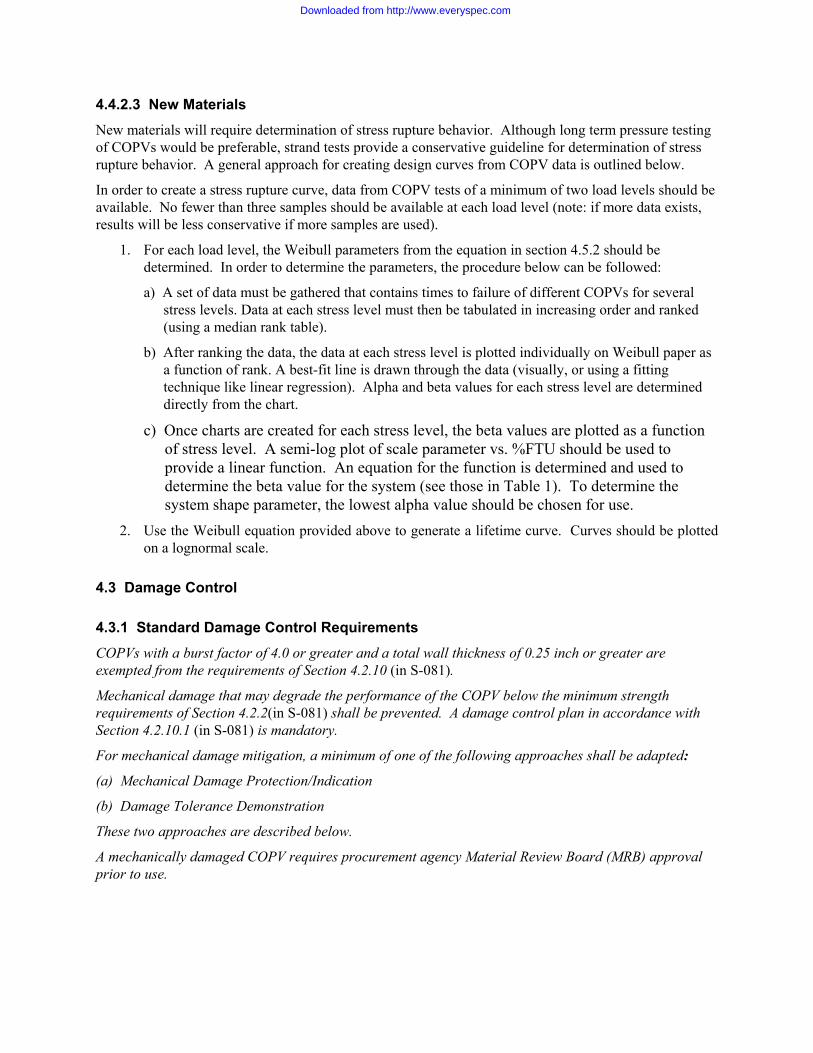
4.3.2.1 Overview of Impact-Damage Control Plan A general overview of an impact damage control plan is illustrated in Figure 1. The impact-damage control plan should be implemented at every stage throughout the life of the COPV beginning at the manufacturing plant, through the various test and integration stages leading up to launch.
In general, the impact-damage control plan should be implemented using at least one of three basic methodologies:
1) By procedure only
2) Using impact indicators
3) Using an impact protection system
The first method, by procedure only, requires 100% Quality Assurance (QA) surveillance to ensure that no damage has occurred to the COPV. QA personnel must be trained and certified in the impact damage susceptibility of COPVs and in the methods of performing nondestructive evaluation (NDE), including visual inspections.
The second method is to use impact indicators to identify any impact conditions, and reduces the level of required QA surveillance to inspections during the installation of the impact indicators and to periodic inspections thereafter.
The third method is to use impact protection system that is capable of absorbing the indentation and deflection damage from all potential impact scenarios in the threat environment. This method requires only QA surveillance during the installation and removal of the COPV protective covers.
A diagram for assessing the BAI of an impact-damaged COPV or suspect impact-damage condition is illustrated in Figure 1. In general, the assessment involves a review of the impact damage history, characterization of the extent of damage using visual and NDI methods, comparison of the data with impact damage databases, and making a theoretical or empirical prediction of the BAI. The BAI prediction methodology should be substantiated by test data. The BAI should be predicted to within ±5% in order to provide sufficiently accurate data to accept or reject a damaged COPV.
Downloaded from http://www.everyspec.com

Installation & Test Procedure Requirements
Procedural Only Impact Indicators Impact Protectors
Reject COPV
Flight Readiness Review
Accept COPV
Assess COPV BAI
Impact Damage Event
Flight Readiness Review
No Impact Damage Event
Impact Damage Evalutation
Receiving Inspection Requirements
Shipping Requirements
Manufacturer Impact Control Requirements
Impact Damage Control Plan
Figure 4. Impact damage control plan overview (Ref.10).
4.4 Impact Damage Tolerance Demonstration
4.4.1 Standard Requirements
Impact damage shall be induced using a drop type impactor and a 0.5-in. (13-mm) diameter, steel hemispherical tup. A pendulum-type arrangement may be used if an analysis substantiates energy and momentum levels equivalent to a drop test. The minimum energy level shall be the greater of the worst case threat, or visual damage threshold (VDT). After inducing damage to the COPV, verification of the capability to satisfy the strength requirements of Section 4.2.2 shall be demonstrated by test. The damage shall be induced in the most damage critical condition (e.g. pressurized vs. unpressurized) and location.
4.4.2 Guidance for Impact Damage Control Impact damage is generally caused by improper handling or impacts associated with work about or above the COPV. Most plausible damage events affecting the encapsulating composite overwrap of the COPV should be assessed by evaluating its burst strength after impact (BAI). The following approaches for the impact damage tolerance demonstration are based on this assessment program.
1. An assessment should be made that includes credible impact conditions, impact locations, pressurization conditions, and environmental conditions. The assessment should identify drop heights, velocities of potential impacts, masses of objects, and the shape for each object. The threat analysis of the post fabrication handling damage of the COPV design performed in the system analysis should be used for damage tolerance assessment. This assessment may make use of similarity data from prior programs using similar metal liner materials, metal liner diameter-to-thickness ratio, composite materials, composite thickness, and laminate design, or by
Downloaded from http://www.everyspec.com
development test data for the COPV. Impact damage effects assessment results conducted by a government/industry team are shown in Appendix B.
2. After the completion of the assessment, the results should be used to establish the visual damage threshold (VDT) of a specific COPV design. This can be done by the application of impact event on the COPV at the pre-selected locations and impact conditions. After the impact event, the visual inspection is then performed. The inspection should be performed by the inspector(s) with formal training in inspecting impact damages on COPVs. Multiple impacts can be applied on the same test article. Full scale COPV(s) should be used to avoid any scaling effect concerns. Multiple impacts at different conditions can be applied on the same test article provided a minimum distance is kept. As the rule of thumb, the minimum distance should be ten times the impactor size.
3. After the establishment of VDT for a specific COPV design, an undamaged COPV should be used as the test article for impact damage tolerance demonstration. The VDT level impact should then be applied on the test article at the most critical location at the worst case pressure level. The stress analysis results should be used to select the locations. Visual inspections should be performed to verify that the impact is indeed not visible or barely visible. After the visual inspection, the test article should be placed in the burst test chamber and pressurized to failure. The pressure at burst is the burst-strength after-impact (BAI).
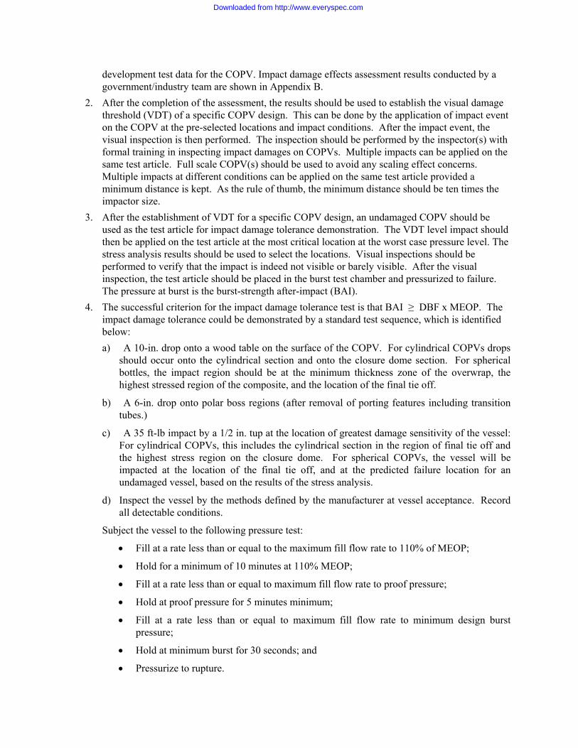
4. The successful criterion for the impact damage tolerance test is that BAI ≥ DBF x MEOP. The impact damage tolerance could be demonstrated by a standard test sequence, which is identified below: a) A 10-in. drop onto a wood table on the surface of the COPV. For cylindrical COPVs drops
should occur onto the cylindrical section and onto the closure dome section. For spherical bottles, the impact region should be at the minimum thickness zone of the overwrap, the highest stressed region of the composite, and the location of the final tie off.
b) A 6-in. drop onto polar boss regions (after removal of porting features including transition tubes.)
c) A 35 ft-lb impact by a 1/2 in. tup at the location of greatest damage sensitivity of the vessel: For cylindrical COPVs, this includes the cylindrical section in the region of final tie off and the highest stress region on the closure dome. For spherical COPVs, the vessel will be impacted at the location of the final tie off, and at the predicted failure location for an undamaged vessel, based on the results of the stress analysis.
d) Inspect the vessel by the methods defined by the manufacturer at vessel acceptance. Record all detectable conditions.
Subject the vessel to the following pressure test:
• Fill at a rate less than or equal to the maximum fill flow rate to 110% of MEOP;
• Hold for a minimum of 10 minutes at 110% MEOP;
• Fill at a rate less than or equal to maximum fill flow rate to proof pressure;
• Hold at proof pressure for 5 minutes minimum;
• Fill at a rate less than or equal to maximum fill flow rate to minimum design burst pressure;
• Hold at minimum burst for 30 seconds; and
• Pressurize to rupture.
Downloaded from http://www.everyspec.com

The pressure transducer should be mounted as close as practically possible to the vessel inlet port during pressure testing. Document the results including description of initiation location and deviation of behavior from undamaged burst test specimen.
4.5 Composite Material Strength Design Allowables
4.5.1 Standard Requirements
A-basis strength allowables shall be determined from burst testing of sub-scale and/or full-scale composite vessels. If the A-basis fiber strength was developed from sub-scale vessels, or if the full-scale COPV differs in configuration from the A-basis fiber vessels (e.g. cylinder vs. sphere) then it must be shown analytically that the A-basis fiber strength is valid for the full scale COPV or the A-basis allowable must be adjusted to account for differences between the full scale COPV and the A-basis vessels. This data shall be used to establish ultimate strength for the fiber/resin system.
The A-basis allowables shall be calculated per the procedures in MIL-HDBK-17 and shall include the test results from at least two lots of materials unless all of the vessels are produced from the same lot of material. The results from production vessels of different configurations and sub-scale pressure vessels may be pooled together.
A change in the resin system shall require testing of a minimum of three sub-scale and/or full scale vessels. The population of the mean delivered strength using the new resin system shall be compared to the original delivered strength. The populations are considered equivalent if the variances and means pass the tests of equality (i.e., Levene’s test and the F-test) as described in MIL-HDBK-17.
4.5.2 Guidance for Composite Material Allowable Generation
4.5.2.1 Composite Material Allowable Generated by Full-scale Specimens There are many different approaches that can be used to provide ultimate strength design allowables that are equally valid. The approach selected should have a rationale to support its use. Examples of several approaches are given below. Other approaches not specifically identified may also be used.
1. A preferred approach is to test a sufficient number of full-scale pressure vessels of the production configuration. The test of 30 vessels is recommended when a new yarn or resin is used, but less may be used if historical information exists. The results from production vessels of different configurations may be pooled together where appropriate. Thickness, wrap-patterns, size, and other relevant factors should be considered in pooling the data.
2. Strands impregnated with the production resin have been conducted to establish the variability in yarn strength within and between batches. Several production pressure vessels are burst and used to establish average burst strength and delivered fiber stress. The results from the analysis of the variability of the strand tests are applied to the average burst strength to establish the design allowables. This approach is not universally endorsed but has been used.
3. Use historically established design allowables and use them for the new COPV design. Validate by burst tests of two or more production vessels. There are a variety of valid approaches that can be used when a change is made to a yarn or resin for a production-qualified system. Items 1-3 above can be used for this purpose. Often a reduced test program is conducted justified by knowledge of the chemistry and/or properties of the resin or yarn and their similarity to those
Downloaded from http://www.everyspec.com

used on a previously qualified COPV. Examples of approaches that are used are described below. Technically supportable options other than those described may be used.
4. When the resin or any of the components used to make a resin or the yarn are changed, a test program should be conducted on full scale COPVs. A preferred approach is to test a sufficient number of COPVs so that the techniques in MIL-STD-17 (Ref.11) can be applied to show that the mean strength and variance for the new and previously used resin are equal to or greater than that previously used. For the normal scatter of results one can expect that between 10 and 20 COPVs would need to be tested.
5. When the resin or any of the components used to make a resin or the yarn is changed, a test program should be conducted on a minimum of three full-scale COPVs. The mean strength should be compared to that obtained with the previously used resin and be equal to or greater than for the materials previously used. A judgment is made based on the results if the new COPV is acceptable or not. This approach is not as analytically rigorous as the approach in 5, above.
4.5.2.2 Composite Materials Allowables Generated by Subscale Specimens Ideally, allowables for composite materials would be generated by testing of full-scale specimens, as the material allowables appear to be configuration dependent. However, this may not be economically feasible when the full-scale part is large. Sub-scale test specimens may be used, but care must be taken to obtain valid results.
Sub-scale test specimens must use the same fiber and resin materials as intended for the full-scale part, and the same relation of helical and hoop fiber thickness should be maintained. Since the same fiber must be used, and the tow cross-sectional area is not scalable, a sub-scale with a smaller diameter must have either thinner layers or fewer layers than the full scale part, or else the burst pressure must be higher. These problems with scaling may cause the fiber strength allowable to be affected. Past testing has shown that as part diameter increases, the apparent fiber strength may decrease. If strength decreases on the full-scale part, and no correction is made, mission reliability and success may be affected. Past testing has also shown that as burst pressure increases, the apparent fiber strength may decrease. This is due in part to thick-wall effects, which are more pronounced in composite materials since their orthotropy ratio is higher than for metals.
Differences in the wall thickness and thickness-to-diameter ratios interact with other aspects of part design and manufacture. Winding times, cure rates, residual stresses, and local discontinuities such as fiber crossovers or band terminations cannot be fully scaled.
The closer the diameters of the full-scale part and the sub-scale specimen, the better the chances of having a valid fiber strength allowable. If economics favor use of a small sub-scale specimen for primary testing, the use of an intermediate sub-scale might improve strength predictions for the full scale. For example, if 60 specimens were desired to establish an A-basis strength allowable, a one-tenth scale specimen might be appropriate. If a limited number (e.g., 3–6) of one-half scale specimens were also tested, the effects of diameter could be evaluated and projections made for the allowable on the full-scale part.
Cylindrical sub-scales which are shorter than the full scale are also useful. The cylinder section of the sub-scale should be long enough to properly address the dome-cylinder junction discontinuities and dissipation of them. Closeness of the helical wind pattern (e.g., single loop vs. multi-loop closure) should also be considered.
Use of a spherical pressure vessel to develop allowable fiber strengths for a cylindrical pressure vessel, or vice versa, offers more challenges to establishing acceptable allowables for a full-scale part. Additional testing may be required to show that using specimens of a different configuration will yield valid results.
Downloaded from http://www.everyspec.com
Tubular specimens under tension or combined tension and internal pressure, flat specimens loaded in tension, or strand tensile specimens should not be used to establish fiber strength allowables for a pressure vessel. Edge effects, size effects, discontinuities at loading points, and differences in three-dimensional stress states limit their value in determining fiber strength allowables in a pressure vessel.
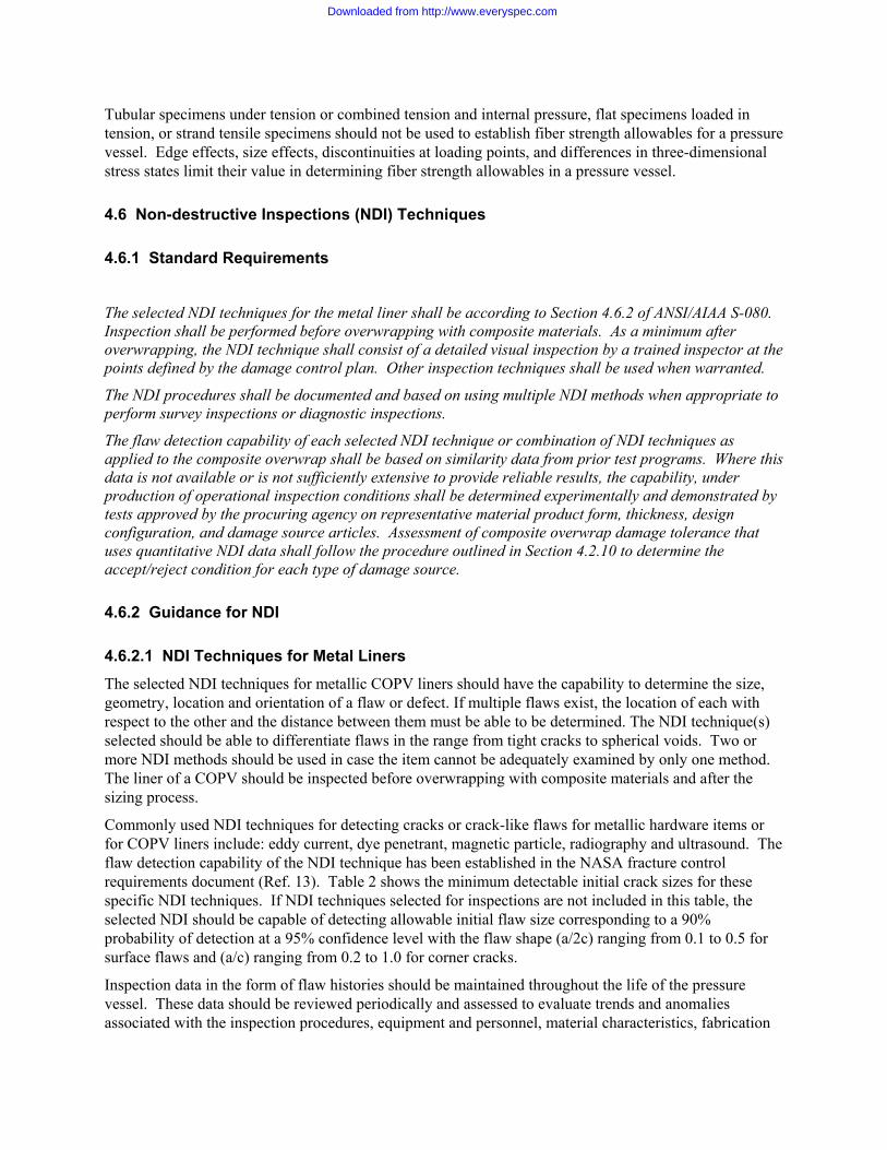
4.6 Non-destructive Inspections (NDI) Techniques
4.6.1 Standard Requirements
The selected NDI techniques for the metal liner shall be according to Section 4.6.2 of ANSI/AIAA S-080. Inspection shall be performed before overwrapping with composite materials. As a minimum after overwrapping, the NDI technique shall consist of a detailed visual inspection by a trained inspector at the points defined by the damage control plan. Other inspection techniques shall be used when warranted.
The NDI procedures shall be documented and based on using multiple NDI methods when appropriate to perform survey inspections or diagnostic inspections.
The flaw detection capability of each selected NDI technique or combination of NDI techniques as applied to the composite overwrap shall be based on similarity data from prior test programs. Where this data is not available or is not sufficiently extensive to provide reliable results, the capability, under production of operational inspection conditions shall be determined experimentally and demonstrated by tests approved by the procuring agency on representative material product form, thickness, design configuration, and damage source articles. Assessment of composite overwrap damage tolerance that uses quantitative NDI data shall follow the procedure outlined in Section 4.2.10 to determine the accept/reject condition for each type of damage source.
4.6.2 Guidance for NDI
4.6.2.1 NDI Techniques for Metal Liners The selected NDI techniques for metallic COPV liners should have the capability to determine the size, geometry, location and orientation of a flaw or defect. If multiple flaws exist, the location of each with respect to the other and the distance between them must be able to be determined. The NDI technique(s) selected should be able to differentiate flaws in the range from tight cracks to spherical voids. Two or more NDI methods should be used in case the item cannot be adequately examined by only one method. The liner of a COPV should be inspected before overwrapping with composite materials and after the sizing process.
Commonly used NDI techniques for detecting cracks or crack-like flaws for metallic hardware items or for COPV liners include: eddy current, dye penetrant, magnetic particle, radiography and ultrasound. The flaw detection capability of the NDI technique has been established in the NASA fracture control requirements document (Ref. 13). Table 2 shows the minimum detectable initial crack sizes for these specific NDI techniques. If NDI techniques selected for inspections are not included in this table, the selected NDI should be capable of detecting allowable initial flaw size corresponding to a 90% probability of detection at a 95% confidence level with the flaw shape (a/2c) ranging from 0.1 to 0.5 for surface flaws and (a/c) ranging from 0.2 to 1.0 for corner cracks.
Inspection data in the form of flaw histories should be maintained throughout the life of the pressure vessel. These data should be reviewed periodically and assessed to evaluate trends and anomalies associated with the inspection procedures, equipment and personnel, material characteristics, fabrication
Downloaded from http://www.everyspec.com

processes, design concept, and structural configuration. The results of this assessment should form the basis of any required corrective action.
Table 2. Minimum Initial Crack Size for Part-Through Cracks
NDE Method Part Thickness t (in.)
Crack Depth a (in.)
Crack Length 2c (in.)
Eddy Current t > 0.050
0.020 0.050
0.200 0.100
Dye Penetrant t > 0.075 0.025 0.075
0.250 0.150
Magnetic Particle t > 0.075 0.038 0.075
0.038 0.250
Radiography 0.025 < t > 0.107 t > 0.107
0.7t 0.7t
0.150 1.4t
Ultrasound t > 0.100 0.030 0.065
0.300 0.130
Reference: NASA-STD-5003, October 7, 1996 (Ref. 12 ).
4.6.2.2 NDI Techniques for Composite Materials The NDI techniques selected for inspecting the composite overwrap of COPVs should follow an approved procedure. An NDI evaluation program has identified the state-of-the-art methods that can be used to detect damage of COPVs. The results are in Appendix B. These methods include visual inspection, thermalgraphy, shearography, ultrasound, and eddy current. Advantages and disadvantages are identified for each method. However, there is no statistical evaluation to determine their probability of detection, as has been established for NDI techniques used for metallic hardware items.
Other techniques may be developed or refined for the application to COPV inspections. For impact damage, visual inspection is an acceptable technique. However, the inspector should have adequate training to inspect impact damage.
4.7 Leak-Before-Burst Demonstration
4.7.1 Standard Requirements When Leak-Before-Burst (LBB) is chosen as the COPV design approach, only the regions of the COPV liner, that are covered by the composite are required to exhibit a LBB failure mode at MEOP. Specifically, the areas of a boss, which are not covered by the composite and remain elastic at all pressures in the service life shall be designed per Section 4.2.7 for safe-life or this section for LBB. The shear region of the boss that is under the composite where the internal pressure is trying to shear the boss through the opening of the composite shall be excluded from both safe-life and LBB design requirements.
When the liner remains elastic at all pressures and/or loads in the service life, linear elastic fracture mechanics shall be used to show that both of the following conditions are satisfied:
(a) An initial part through crack (surface flaw) with a shape (a/2c) ranging from 0.1 to 0.5 shall not fail (cause catastrophic burst) at any stress intensity factor applied during the service life (K<KIe at all times), and
Downloaded from http://www.everyspec.com

(b) This part-through crack shall grow through the wall of the pressure vessel liner to become a through crack with a length equal to ten times the wall thickness thereby leaking out the contents before catastrophic failure (burst) can occur.
LBB Demonstration Testing
When the strain in the liner is elastic at MEOP, LBB shall be demonstrated by analysis, test, or similarity according to Section 4.2.9. When the strain in the liner exceeds the strain at which linear elastic fracture mechanics is applicable at MEOP then the LBB failure mode shall be demonstrated by test or similarity. LBB verification shall establish that all critical areas exhibit LBB.
LBB Demonstration Using Coupons
Testing shall be conducted on uniaxial coupons, which duplicate the materials (wrought materials, weld joints or heat affected zones), processes and the thickness of the COPV liner. The coupons shall start with a surface-crack per Section 4.2.9 and shall meet the requirements for validity of an appropriate method from a published standard of a recognized standards institute for a crack whose length equals ten times the coupon thickness. Cycle loads shall be applied to the test specimen to generate a peak strain corresponding to the strain at MEOP, as determined by analysis. LBB failure mode is demonstrated if the surface crack and breaks through the thickness and grows to a length that is ten times the coupon thickness without causing the coupon to fracture.
LBB Demonstration Using a COPV
A COPV, which is representative of the flight COPV (liner material, processing and thickness, configuration, and reinforcing composite stiffness and thickness) shall be used. Surface cracks shall be put into the liner only at locations and orientations which are most critical to LBB response. An inert fluid shall be used to pressurize the COPV. Pressure cycles shall be applied to the COPV, with the upper pressure equal to MEOP. LBB failure mode is demonstrated if the crack leaks the pressure from the COPV at MEOP before catastrophic failure occurs.
4.7.2 Guidance for LBB Demonstration For metallic pressure vessels, and elastic response metal liners of COPVs, the LBB demonstration can be done by either a fracture mechanics based analysis or by LBB test. For plastic response COPV metal liners, test is the only acceptable method to demonstrate LBB failure mode
For metallic pressure vessels, the “10 x thickness” requirement was introduced by NASA/Johnson Space Center (Ref. 12). It implies that the crack opening should be large enough to cause fast pressure release. For a typical spacecraft pressure vessel, the thickness is around 0.05 in. Thus a 0.5 in. long crack is considered large enough to cause fast pressure release especially for helium gas storage. This size limitation was adapted in S-080. For the metal liner of a COPV, the same crack length requirement is adapted in S-081. When metallic material is in the elastic range, linear elastic fracture mechanics should be used in the failure mode predictions, i.e., K(10t) < Kc, where Kc is the plane stress fracture toughness of the material.
For plastically responsive metal liners of COPVs, the LBB demonstration should be conducted at the strain levels determined by elastic-plastic analysis at the undamaged state. If the full scale COPV is to be used, the initial flaws are better fabricated on the outer surface of the liner using the electric discharge machining (EDM) process before it is overwrapped with composite materials. However, if there is a large enough opening in the port area for the EDM process, the initial flaws could be fabricated on the inner surface of the liner after the liner is overwrapped.
Downloaded from http://www.everyspec.com
The initial EDM size and shape of the prefabricated flaws should be carefully selected such that fatigue pre-cracking cycles can be applied in order to initiate the sharp fatigue crack at the tip of the EDM notch. If a full scale COPV is used as the test specimen, crack growth should be closely monitored. After the part-through crack penetrates through the thickness of the COPV, leakage may have developed and the internal pressure of the vessel may drop very fast. Before the crack length reaches to ten-times the wall thickness, internal pressure should be maintained by pumping the vessel with more test fluid. When the pump rate increases to its maximum allowable rate and still cannot overcome the leakage, the test should be discontinued. Under this condition, LBB is considered to have been demonstrated.
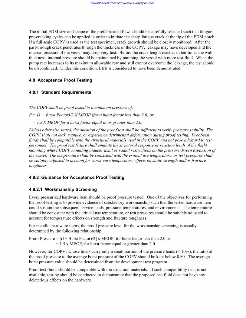
4.8 Acceptance Proof Testing
4.8.1 Standard Requirements
The COPV shall be proof tested to a minimum pressure of:
P = (1 + Burst Factor)/2 X MEOP (for a burst factor less than 2.0) or
= 1.5 X MEOP for a burst factor equal to or greater than 2.0.
Unless otherwise stated, the duration of the proof test shall be sufficient to verify pressure stability. The COPV shall not leak, rupture, or experience detrimental deformation during proof testing. Proof-test fluids shall be compatible with the structural materials used in the COPV and not pose a hazard to test personnel. The proof test fixture shall emulate the structural response or reaction loads of the flight mounting where COPV mounting induces axial or radial restrictions on the pressure driven expansion of the vessel. The temperature shall be consistent with the critical use temperature, or test pressures shall be suitably adjusted to account for worst-case temperature effects on static strength and/or fracture toughness.
4.8.2 Guidance for Acceptance Proof Testing
4.8.2.1 Workmanship Screening Every pressurized hardware item should be proof pressure tested. One of the objectives for performing the proof testing is to provide evidence of satisfactory workmanship such that the tested hardware item could sustain the subsequent service loads, pressure, temperatures, and environments. The temperature should be consistent with the critical use temperature, or test pressures should be suitably adjusted to account for temperature effects on strength and fracture toughness.
For metallic hardware items, the proof pressure level for the workmanship screening is usually determined by the following relationship:
Proof Pressure = [(1+ Burst Factor)/2] x MEOP, for burst factor less than 2.0 or = 1.5 x MEOP, for burst factor equal or greater than 2.0
However, for COPVs whose liners carry only a small portion of the pressure loads (< 10%), the ratio of the proof pressure to the average burst pressure of the COPV should be kept below 0.80. The average burst pressure value should be determined from the development test program.
Proof test fluids should be compatible with the structural materials. If such compatibility data is not available, testing should be conducted to demonstrate that the proposed test fluid does not have any deleterious effects on the hardware.
Downloaded from http://www.everyspec.com

Accept/reject criteria should be formulated prior to acceptance proof test. As a minimum, the hardware item should not experience measurable pressure decay as a result of leakage, rupture, or experience detrimental deformation during the acceptance proof test and should successfully complete subsequent post-proof test NDI. As a minimum, the post-proof NDI should be conducted in the weld region. This is because that defects contained in the weld region could extend during the proof test. This is particularly essential for a metallic pressure vessel (MPV) or a metallic pressurized structure (MPS) that the stress in the weld is in the plasticity range during the proof test.
4.9 Vibration/External Load Testing
4.9.1 Standard Requirements
A maximum expected flight-level vibration environment shall be established from the predominant vibration source encountered during the mission. Qualification testing shall be performed using an environment that produces twice the power for three times the duration for each orthogonal axis. Vibration testing shall be conducted at the launch pressure condition with the vessel mass being equivalent to the operational configuration.
4.9.2 Guidance for Vibration/External Load Testing There are a few techniques that can be used to meet the specified test requirements.
However, whatever the technique selected, the following requirements apply:
a. Environmental load fixture designs should be provided to the procurement agency for review and approval.
b. Control logic and response limitation techniques will be pre-declared and approved by the procurement agency.
If not defined by the procuring agency, the COPV should be mounted to a fixture through the normal mounting points. The vessel should be tested in a minimum of two axes, the mutually independent longitudinal and lateral axes. The mounting fixture(s) should be designed to provide proper stiffness or reaction loads at the mount points. For vibration tests, significant resonant frequencies of the bare mounting fixture and mounted vessel in the fixture should be noted and recorded.
1) Random Vibration Test
The test shall be run 6 dB over flight levels for the flight duration or at 3 dB over flight levels for a duration 4 times that experienced in flight. The tolerances shall be:
(a) ±1.5 dB from zero to 500 Hz and
(b) ±3 dB from 500 to 2000 Hz.
Additional local excursions from these tolerances over a maximum bandwidth of 100 Hz are allowable as specified below:
+ 3 dB over 100 Hz bandwidth from 500 to 2000 Hz
The overall RMS level shall be ±10% about the nominal specified value.
Programmed notches to limit COPV response about the first mode responses in the mutually independent axes shall be permitted if approved by the procurement agency.
Downloaded from http://www.everyspec.com

2) Sine Vibration Test
Sinusoidal vibration may be applied as a dwell at discrete frequencies or as a frequency sweep with the frequency varying at a logarithmic rate. The maximum permissible sweep rate is two octaves per minute.
The test shall be conducted at an amplitude 25% above flight levels for flight duration.
The tolerance about the nominal input level is ±10%.
Programmed notches to limit COPV response about the first mode responses in the mutually independent axes shall be permitted if approved by the procurement agency.
3) Acoustic Test
The COPV shall be fully loaded and tested at the greatest acoustic value anticipated. The mounting fixture shall emulate the stiffness of the flight system seen by the COPV.
4) Equivalent Static Load Test
Static load testing, in combination with qualification pressure cycle test data, may be used in lieu of vibration testing if it can be demonstrated that the static load test, applied with the appropriate resident pressure, envelopes the qualification level external loads. The demonstration of static structural margins and life margins associated with the number of load application cycles, which would occur under the qualification dynamic excitation environment at the mounting point(s), is required. The analytical assumptions relating to the modal responses and transmissibility of the structure used in defining the equivalent static load shall be fully documented and supported by prior testing on similar hardware.
5) Shock Test
Shock test is required only if the equivalent external load for critical areas of the COPV is not enveloped by the vibration or static load tests.
4.10 Leak Test
4.10.1 Standard Requirements The COPV shall be leak tested after pressure cycling to verify the compliance with the requirements.
4.10.2 Guidance for Leak Test Leak test should be performed after proof-pressure test. During the leak check, the pressure level should be maintained at MEOP for 30 minutes minimum after the background has stabilized if the test leak rate is 1x10⁻⁶ SCC /sec or higher. If the test leak rate is less than 1x10⁻⁶ scc/sec (e.g. 1x10⁻⁷ SCC/Sec), the pressure level should be maintained at MEOP for an approximately longer than 30 minutes.
If hydrocarbon contaminants, such as oils or other liquids are introduced into the tank prior to leak test, the tank should be cleaned and dried prior to leak test to prevent corruption of the leak test due to leak signature scavenging by the contaminant. In any case, as a minimum, the vessel should be dried before leak testing. Required end item cleanliness is not necessary to conduct a valid leak test.
Response time characterization of the test apparatus should have been performed and documented prior to conducting a leak test and should be repeated if the test chamber or fixture is subjected to substantive rework or refurbishment. The response time of the system should be used to establish the required hold time of the vessel at the test pressure.
The temperature of the vessel should be monitored during fill and venting to ensure that safe operational limits are not exceeded. Both the metallic end-fittings (if present) and the composite overwrap should be
Downloaded from http://www.everyspec.com
monitored. The maximum and minimum temperatures experienced by these elements during leak test should be recorded.
The leak test should be conducted using a certified and a calibrated system. System calibration is in addition to sensor instrumentation calibration. Calibration should be done at a minimum of one decade below the maximum specified leak rate for the vessel using a standard rate.
Mechanical fitting isolation from the vessel leak signature is permissible if it is shown that the isolation of fittings does not scavenge the leak signature from the vessel.
5. Specific Topics
Downloaded from http://www.everyspec.com

5.1 Development Testing The purposes of the development testing are:
a) Reduce qualification program risk; b) Supplement the rationale for hardware certification, as applicable; c) Validate adequate safe-life margin; d) Demonstrate adequate fatigue life; and e) Demonstrate damage tolerance capability.
Development tests should be conducted on every new hardware design before commitment to the production. Success criteria should be formulated prior to tests. It should be also conducted on an existing design that has significant modifications.
The number of tests and the types of tests required to demonstrate proof of concept/design will depend on the design principles employed with an acceptable degree of confidence. The following are pertinent guidelines:
a) Selection of the instrumentation for the purpose of characterizing or quantifying a critical parameter should be based on high confidence and probability of detection (POD) and the ability to define/characterize the essential properties. The instrumentation types and their locations should be determined based on the results of the stress analysis in addition to considerations in regard to the selection of the instrument. The instrumentation selected and test plans developed should provide sufficient data to determine the accept/reject basis;
b) The test sequence should be designed to measure vessel parameters due to, at a minimum, worst case singular/combined effects resulting from proof cycles, life cycle, and expected operating environments;
c) The test sequence should be designed to account for combinations of loads, levels and duration of loads, pressures, and environmental effects. For example, the test sequence for a COPV design should include employment of techniques to evaluate the effects and changes in characteristics of the metal liner and composite overwrap properties resulting from the tests;
d) Evaluate the effects of external loads caused by supports. The supporting structure for the pressure vessel should be a replica or structure that accurately replicates the loading scenario on the flight vehicle;
e) Evaluate parameters and provide conservative limits to address the effects of thermal and mechanical shock (due to pressure cycling, variations in flow, system configuration changes and external factors) on the PV or the PS using full-scale test articles affixed to a replica of the support structure to be used; and.
f) The test sequences should be suitable to demonstrate that the design requirements can be met.
5.2 Qualification by Similarity There are situations in which a pressurized hardware item can be qualified by similarity. Usually, this provision should apply to one-of-a-kind hardware items, to out-of-the-shelf items, or to a small production program where the test article is expensive and there is a compressed schedule. This provision could be applied to the whole qualification test program or a portion of it. Recommended conditions for conducting a reduced qualification burst test was proposed by J.P Lewis (Ref. 15). They are shown in Table 3. To meet the conditions set in this table, the temperature effects should be assessed.
Table 3. Recommended Conditions for Qualification by Similarity
Downloaded from http://www.everyspec.com

(X Denotes Required Test)
Deviation from
Previously Qualified Vessel
LBB
Demonstration1
Safe-Life
Demonstration
Dynamic/Static
Load Test
Pressure
Cycle Test
Burst Test
New Design2 X X X X X Increased Length X X X Decreased Burst Factor/Increase MEOP
X X X X
Decreased Diameter X3 Increased Diameter X X X X X Increased Composite Thickness
X3
Decreased Composite Thickness
X X X X X
Increased Liner Thickness
X X X3
Decreased Liner Thickness
X X X X X
Change Proof Pressure X X X X Chance Autofrettage Pressure
X X X X
Change Mounting X4 X X4 X Notes: 1. LBB failure mode may be qualified by similarity when both the liner and vessel thickness and strain at
MEOP are less than or equal to those of previously qualified vessels. 2. Changes in head shape, liner material, liner heat treatment, composite materials, wrap pattern, and boss
dimensions(including boss taper) are considered to be a new design. 3. A delta-qualification test may be required if analysis of the dynamic environments, stiffness, natural
frequency, and mass indicate higher stresses for new (modified) designs. 4. Test is required only if new mounting constrains the tank shell expansion more than mounting in
qualification test.
Downloaded from http://www.everyspec.com

6.0 References
1. Anon, Standard General Requirements for Safe Design and Operation of Pressure Missile And Space Systems, MIL-STD-1522, USAF,1972.
2. Anon, Standard General Requirements for Safe Design and Operation of Pressurized Missile And Space Systems, MIL-STD-1522A, USAF,1984. 3. Chang, J.B. Lou, M.C. and Huang, L. C-P, Updated Requirements for Pressurized Space Systems, PVP-Vol. 318, The American Society for Mechanical Engineers,1995. 4. Anon, Space Systems-Metallic Pressure Vessels, Pressurized Structures, and Pressure Components,
ANSI/AIAA S-080-1998, American National Standard Institute and American Institute of Aeronautics and Astronautics, 1998.
5. Anon, Space Systems-Composite Overwrapped Pressure Vessels, ANSI/AIAA S-081-2000, American National Standard Institute and American Institute of Aeronautics and Astronautics, 2000. 6. Horton, R.E., et al, “Damage Tolerance of Composites-Final Report”, AFWAL-TR-87-3030, 1988. 7. Chang, J.B., Enhanced Technology for Composite Overwrapped Pressure Vessels, Technical
Summary Final Report, Aerospace Report No. TR-99(8504)-1, 2000. February 2000. 8. Chang, J.B. Chiu, S.T. and Huang, L. C-P, “Damage Control of Space-Flight Composite
Overwrapped Pressure Vessels,” IAF-00-I.3.10, 51st International Astronautical Congress, 2000.
9. Babel, H. and Grimes, L., AIAA Space Pressure Vessel Working Group Meeting Presentation
Materials, 1998. 10 Ralph M. Tapphorn, Test Report, Impact Damage Effects and Control Applied to Composite
Overwraapped Pressure Vessels, TR-806-001, NASA Johnson Space Center, White Sands Test Facility, July 29, 1998.
11 Anon, Polymer Matrix Composites, MIL-HDBK-17E, January 1997. 12 Anon, Fracture Control Requirements for Payloads Using the Space Shuttle, NASA-STD-5003,
NASA/ Headquarters, 199 13 Johnson, E. and Nokes, J.P., Nondestructive Evaluation (NDE) Techniques Assessment for
Graphite/Epoxy (GR/Ep) Composite Overwrapped Pressure Vessels, Aerospace report, TR-908(8504)-3, October 1998.
14 Anon, Fracture Control Implementation Handbook for Payloads, Experiments, and Similar Hardware,
NASA-HDBK-P020, Draft, June 2002. 15 Lewis, J. AIAA Space Pressure Vessel Working Group Meeting Presentation Materials, 1999.
Downloaded from http://www.everyspec.com

Downloaded from http://www.everyspec.com

Downloaded from http://www.everyspec.com
Appendix A ANSI/AIAA S-081 Requirements
This appendix contains the general requirements and the specific requirements specified in ANSI/AIAA S-081-2000, Space Systems-Composite Overwrapped Pressure Vessels (COPVs). The section numbers are consistent with those in the original document.
4. General Requirements This standard presents the general requirements for the design, analysis, and verification of COPVs. The results of all analyses and tests shall be documented in reports containing all significant and relevant data, methods, models, assumptions, and results.
4.1 System Analysis Requirements A system analysis shall be performed per the applicable requirements of Section 4.1 of ANSI/AIAA S-080 to establish design and performance requirements for the COPV.
4.2 General Design and Analysis Requirements One of the two following alternative approaches for the design, analysis and verification of COPVs shall be selected: (a) LBB or safe-life for non-hazardous fluid applications, (b) Safe-life for hazardous fluid applications.
4.2.1 Loads, Pressures, and Design Environments
The anticipated load-pressure-temperature history and associated environments throughout the service life shall be used to define the design load/environment spectra which shall be used for both design analysis and testing. Updates to the design spectra shall be evaluated to ensure positive margins prior to flight. Environmental testing (i.e. vibration, acoustic, shock, equivalent static load, etc.) shall be conducted per the direction of the procurement agency. The procurement agency shall select the tests and provide the environmental loads and levels. The procurement agency is also responsible for the definition of performance requirements and applicable operational and non-operational environments.
4.2.2 Strength Requirements
All COPVs shall possess sufficient strength to withstand limit loads and simultaneously occurring internal pressures in the expected operating environments throughout their respective service lives without experiencing detrimental deformation. They shall also withstand ultimate loads and simultaneously occurring internal pressures in the expected operating environments without experiencing rupture or collapse.
They shall be capable of withstanding ultimate external loads and ultimate external pressure (destabilizing) without collapse or rupture when internally pressurized to the minimum launch pressure.
They shall sustain proof pressure without detrimental deformation and shall sustain design burst pressure without burst. When proof tests are conducted at temperatures other than the design temperatures, the change in material properties at the proof test temperature shall be accounted for in determining proof pressure. The margin of safety shall be positive and shall be determined by analysis or test at design ultimate and design limit loads levels, when appropriate, at the temperature expected for all critical conditions.
The margins of safety shall be based on A-basis allowables for the liner and composite.
Downloaded from http://www.everyspec.com

The minimum burst factor shall be 1.5. The stress ratio rupture requirements of Section 4.2.8 shall also apply.
4.2.3 Stiffness Requirements
COPVs shall possess adequate stiffness to preclude detrimental deformation at limit loads and at pressures in the expected operating environments throughout their respective service lives. The stiffness properties of the mounted COPV shall be such as to prevent all detrimental instabilities of coupled vibration modes. This is to minimize detrimental effects of the loads and dynamics response, which are associated with structural flexibility of the vessel and its interface mounting, and to allow the vessel to remain within the specified static and dynamic envelope.
4.2.4 Thermal Requirements
Thermal effects, including heating and cooling rates, temperatures, thermal gradients, thermal stresses and deformations, and changes in the physical and mechanical properties of the material of construction, shall be considered in the design of all COPVs. These effects shall be based on temperature extremes predicted for the operating environment plus a design margin as appropriate.
4.2.5 Stress Analysis Requirements
A detailed and comprehensive stress analysis of each COPV design shall be conducted with the assumptions that no crack-like flaws exist in the metallic liner, and there are no defects in the overwrap. The analysis shall determine stresses resulting from the combined effects of internal pressure, ground or flight loads, temperatures, and thermal gradients. Both membrane stresses and bending stresses resulting from internal pressure and external loads shall be calculated to account for the effects of geometrical discontinuities, design configuration, and structural support attachments. The analysis shall include the effects of adding stresses from restraints, manufacturing tolerances, test conditions, residual stresses, and assembly stresses. Thermal effects, including heating rates, temperatures, thermal gradient, thermal stresses and deformations, and changes in the physical and mechanical properties of the material of construction shall be considered in the stress analysis.
Loads shall be combined by using the appropriate design limit or ultimate safety factors on the individual loads and comparing the results to A basis allowables. Design safety factors on external (support) loads shall be as assigned to primary structure supporting the pressurized system.
Finite element or other proven equivalent structural analysis techniques shall be used to calculate the stresses, strains, and displacements for complex geometries and loading conditions. Local structural models shall be constructed, as necessary, to augment the overall structural model in areas of rapidly varying stresses. The analysis tools used for the structural assessment shall be correlated against past test results for the class of vessel shape and lamination analyzed to demonstrate the accuracy of the methodology. The analytical tool verification shall be submitted as part of the analysis report.
Elastically responding regions of the metallic liner shall be analyzed according to the requirements of ANSI/AIAA S-080, Section 4.2.5. Residual stresses shall be considered in the stress analysis.
Plastically responding regions of the metallic liner shall meet all requirements defined in this document. Residual stresses shall be considered in the stress analysis.
A methodology using composite laminate theory shall be employed to analyze the composite. Effects of ply orientation, stacking sequence, and geometrical discontinuities shall be assessed. The effect of variation in thickness gradients and in material thickness, as specified in the design documentation shall be used in calculating the stresses and strains in the liner and composite. The margins of safety shall be positive for all load conditions on the COPV
Downloaded from http://www.everyspec.com

4.2.6 Fatigue-Life Requirements
A fatigue analysis is required to demonstrate the fatigue life of an unflawed COPV. Nominal values of fatigue-life characteristics for metal liners and composite overwraps including stress-life (S-N) data and/or strain-life (ε - N) data of the structural materials shall be used. These data shall be taken from reliable sources such as MIL-HDBK-5, the Aerospace Structural Metals Handbook, and MIL-HDBK-17. The analysis shall account for the spectra of expected operating loads, pressures, and environments. The conventional fatigue damage accumulation technique, Miner's rule (Σn/N), is an acceptable method for handling variable amplitude fatigue cyclic loading. Unless otherwise specified, a life factor of four (4) shall be used in the fatigue analysis. The limit for accumulated fatigue damage shall be 80% of the normal limit. For elastically responding metal liners, the requirements of ANSI/AIAA S-080, Section 4.2.6 shall be used for the analysis. For plastically responding metallic liners, the analysis shall address all strain excursions for all spectra of expected operating loads, pressures, and environments. For the composite elements of the COPV, the analysis shall address the alternating stress response for all spectra of expected operating loads, pressures, and environments. Testing of unflawed specimens to demonstrate fatigue-life of specific hardware together with stress analysis is an acceptable alternative to analytical prediction. Fatigue-life requirements are considered demonstrated when the unflawed specimens successfully sustain the limit loads and MEOP in the expected operating environments for the specified test cycles and duration without rupture. Unflawed specimens shall represent critical areas such as membrane section, weld joints, heat-affected zone, and boss transition section, including representative overwrap layers as appropriate. The required test duration is four (4) times the specified service life or number of cycles.
4.2.7 Safe-Life Requirements
Safe-life requirements shall apply to the metallic liner and to integral bosses. The overwrap shall be assumed to be unflawed. For elastically responding metallic liners and integral bosses, and for elastically responding regions of a generally plastic responding liner, the safe life analysis requirements of ANSI/AIAA S-080, Section 4.2.7 shall apply. For plastically responding regions of metallic liners, testing is the only acceptable method to demonstrate safe-life since no generally accepted elastic/plastic analytical method is available. The test requirements of Section 5.1 shall apply. A life factor of four (4) shall be used in the safe-life testing. For those COPVs, which are readily accessible for periodic inspection and repair, the safe-life shall be at least four (4) times the interval between scheduled inspection and/or refurbishment. A safe-life report shall be prepared to delineate the following: (a) Loading spectrum and environments; (b) Non-destructive evaluation (NDE) method(s) and corresponding initial flaw sizes; (c) Strain analysis assumptions and rationale; (d) Summary of significant results; (e) References; (f) Material property reference list; and (g) Summary of test data generated in support of safe life assessment.
Downloaded from http://www.everyspec.com

This report shall be closely coordinated with the stress analysis report.
4.2.8 Stress-Rupture Requirements
The COPV shall be designed to meet the design life considering the time it is under sustained load. There shall be no credible stress rupture failure modes based on stress rupture data for a probability of survival of 0.999. To meet the stress rupture requirements, the lowest fiber reinforcement stress ratio at MEOP shall be: Carbon = 1.5 Aramid = 1.65 Glass = 2.25
4.2.9 Leak-Before-Burst Requirements
When Leak-Before-Burst (LBB) is chosen as the COPV design approach, only the regions of the COPV liner, that are covered by the composite are required to exhibit a LBB failure mode at MEOP. Specifically, the areas of a boss, which are not covered by the composite and remain elastic at all pressures in the service life shall be designed per Section 4.2.7 for safe-life or this section for LBB. The shear region of the boss that is under the composite where the internal pressure is trying to shear the boss through the opening of the composite shall be excluded from both safe-life and LBB design requirements. When the liner remains elastic at all pressures and/or loads in the service life, linear elastic fracture mechanics shall be used to show that both of the following conditions are satisfied: (a) An initial part through crack (surface flaw) with a shape (a/2c) ranging from 0.1 to 0.5 shall not fail (cause catastrophic burst) at any stress intensity factor applied during the service life (K<KIe at all times), and (b) This part-through crack shall grow through the wall of the pressure vessel liner to become a through crack with a length equal to ten times the wall thickness thereby leaking out the contents before catastrophic failure (burst) can occur.
4.2.10 Damage Control Requirements
COPVs with a burst factor of 4.0 or greater and a total wall thickness of 0.25 inch (6 mm) or greater are exempted from the requirements of Section 4.2.10. Mechanical damage that may degrade the performance of the COPV below the minimum strength requirements of Section 4.2.2 shall be prevented. A damage control plan in accordance with Section 4.2.10.1 is mandatory. For mechanical damage mitigation, a minimum of one of the following approaches shall be adapted: (a) Mechanical Damage Protection/Indication (b) Damage Tolerance Demonstration These two approaches are described below. A mechanically damaged COPV requires procurement agency Material Review Board (MRB) approval prior to use.
Downloaded from http://www.everyspec.com

4.2.10.1 Damage Control Plan
The damage control plan shall document the threat analysis and procedures which mitigate these threats. The threat analysis shall document the conditions (source and magnitude of threat and state of pressurization of the COPV) under which mechanical damage can occur. The Damage Control Plan shall delineate all potentially damaging events and investigate mitigating procedures from the point of time when the COPV reinforcing matrix is cured to the end of service life.
4.2.10.2 Approach A - Mechanical Damage Protection/Indication
Protective covers shall provide isolation from a mechanical damage event. Protective covers shall be used when the COPV has not demonstrated sufficient strength per Section 4.2.2 after a mechanical damage incident that is consistent with the worst case credible threat identified in Section 4.2.10.1. The following requirements shall apply for protective covers and /or indicators:
4.2.10.2.1 Protective Covers
The effectiveness of protector covers shall be demonstrated by test Protective covers or standoffs which isolate the vessel are required when personnel will be exposed to pressurized COPVs having stored energy levels in excess of 14,240 ft-lbf (19, 310 joules) or containing hazardous fluids. They shall be designed to completely protect the COPV under the worst credible threat defined in Section 4.2.10.1. They shall allow transmission of less than 5 ft-lbf (6.8 joules) of energy or reduce the transmitted energy to a level not to exceed one half that demonstrated as acceptable by pressurized damage tolerance or residual strength testing. Protective covers shall not be removed until the latest practical time prior to launch or during other critical operations requiring cover removal.
4.2.10.2.2 Indicators
When protective covers are not used, or the indicators are placed between the protective cover and the COPV, the effectiveness of the indicators to provide positive evidence of a mechanical damage event less than or equal to the demonstrated residual strength capability of the unprotected COPV shall be demonstrated by test. If residual strength testing of the COPV is not performed, the indicators shall be capable of detecting a 5 ft-lbf (6.8 joule) impact with a 0.5 in. (13-mm) diameter steel hemispherical tup impactor. When indicators are placed outside of the protective cover, the effectiveness of the indicator to provide a positive evidence of impact in excess of the cover isolation capability shall be demonstrated by test. The use of indicators as the sole means of mitigating threats for pressurized COPVs, as defined in Section 4.2.10.1, during personnel workaround is prohibited.
4.2.10.3 Approach B Damage Tolerance Demonstration
Mechanical damage tolerance demonstration is an alternative to, or complementary with, mechanical damage covers to satisfy the requirements for damage control.
4.2.10.3.1 Impact Damage Tolerance Demonstration
Impact damage shall be induced using a drop type impactor and a 0.5-in. (13-mm) diameter, steel hemispherical tup. A pendulum-type arrangement may be used if an analysis substantiates energy and momentum levels equivalent to a drop test. The minimum energy level shall be the greater of the worst
Downloaded from http://www.everyspec.com

case threat, or visual damage threshold (VDT). After inducing damage to the COPV, verification of the capability to satisfy the strength requirements of Section 4.2.2 shall be demonstrated by test. The damage shall be induced in the most damage critical condition (e.g. pressurized vs. unpressurized) and location.
4.2.10.3.2 Other Mechanical Damage Tolerance Demonstration
Damage tolerance of other mechanical damage such as abrasions and surface cuts shall be demonstrated by analysis or test to verify the strength requirements of Section 4.2.2. The abrasion or cut shall be based on the threat analysis of Section 4.2.10.1.
4.2.11 Corrosion and Stress Corrosion Control and Prevention
Operational, test and manufacturing support fluids that come in contact with the COPV shall be identified, along with the frequency of contact, duration of contact, and fluid temperatures. These fluids shall be compatible with the liner and composite material and not result in stress corrosion cracking or sustained-load failure. Compatibility of the metal liner shall be evaluated as specified in Section 5.2.1.3 Degradation of the COPV from corrosive or incompatible environments shall be prevented and shall meet the requirements specified in Section 5.2.1.3. The design of the COPV shall provide for isolation of the liner from electrically conductive elements in the reinforcing composite matrix.
4.2.12 Embrittlement Control
All known embrittlement mechanisms, such as hydrogen embrittlement, liquid-metal embrittlement, etc. applicable to the liner, fiber, and resin shall be identified and controlled in the design, fabrication, and operation of the COPV.
4.3 Materials Requirements
4.3.1 Metallic Materials
The metallic liner material shall be selected, evaluated, characterized, and controlled per the criteria of Section 4.3.1 of ANSI/AIAA S-080.
4.3.2 Composite Materials
4.3.2.1 Composite Materials Selection
Composite material systems used for COPVs, consisting of a reinforcing filament material impregnated by a resin matrix, shall be selected on the basis of proven environmental compatibility, material strength/modulus, stress rupture properties, and compatibility with metal liner materials. If an electrically conductive fiber reinforcement is used, the design shall incorporate a means to prevent galvanic corrosion with metallic components. The effects of fabrication processes, coatings, fluids and the effects of temperature, load spectra, impact spectra, and other environmental conditions which affect the strength and stiffness of the material in the fabricated configuration shall also be included in the rationale for selecting the composite material system.
4.3.2.2 Composite Material System Characterization
The composite materials selected for the design shall be evaluated with respect to the material processing, fabrication methods, manufacturing operations, refurbishment procedures and processes,
Downloaded from http://www.everyspec.com

operating environments and other pertinent factors which affect the resulting strength and stiffness properties of the material in the fabricated as well as refurbished configurations. The properties of the composite materials selected shall be characterized in sufficient detail to permit reliable and high confidence predictions of the structural performance in their expected operating environments. The supporting data shall provide justification for the declared properties consistent with the operating and non-operating environments.
4.3.2.2.1 Characterization Tests
Uniform test procedures shall be employed for determining material properties as required. These procedures shall conform to a recognized standard. Deviations from standard procedures shall be documented. The test specimens and procedures utilized shall provide valid test data for the intended application.
4.3.2.2.2 Strength Design Allowables
A-basis strength allowables shall be determined from burst testing of sub-scale and/or full-scale composite vessels. If the A-basis fiber strength was developed from sub-scale vessels, or if the full-scale COPV differs in configuration from the A-basis fiber vessels (e.g. cylinder vs. sphere) then it must be shown analytically that the A-basis fiber strength is valid for the full scale COPV or the A-basis allowable must be adjusted to account for differences between the full scale COPV and the A-basis vessels. This data shall be used to establish ultimate strength for the fiber/resin system. The A-basis allowables shall be calculated per the procedures in MIL-HDBK-17 and shall include the test results from at least two lots of materials unless all of the vessels are produced from the same lot of material. The results from production vessels of different configurations and sub-scale pressure vessels may be pooled together. A change in the resin system shall require testing of a minimum of three sub-scale and/or full scale vessels. The population of the mean delivered strength using the new resin system shall be compared to the original delivered strength. The populations are considered equivalent if the variances and means pass the tests of equality (i.e., Levene’s test and the F-test) as described in MIL-HDBK-17.
4.4 Fabrication and Process Control The design of all COPVs shall employ proven processes and procedures for manufacture. MIL-HDBK-17 shall be used as appropriate to address fabrication and process control measures. It is the responsibility of the COPV manufacturer to demonstrate that the processes are qualified for the fabrication of the COPV. The fabrication process shall provide for initial and in-process inspections, and periodic in-service inspection to support safe operation and high probability for mission success.
4.4.1 Liner Fabrication and Process Control
The requirements, as levied by ANSI/AIAA S-080, Section 4.5, shall apply to metallic liner fabrication and process control.
4.4.2 Overwrap Fabrication and Process Control
The composite overwrap fabrication process shall be a controlled documented process. Incorporated materials shall have certifications which demonstrate acceptable variable ranges to ensure repeatable
Downloaded from http://www.everyspec.com

and reliable performance. An inspection plan shall be developed per Section 4.5.1 to identify all critical parameters essential for verification. In-process inspection or process monitoring shall be used to verify the setup, and the acceptability of critical parameters during the filament winding process. The amount of each composite material used on the article from the composite fabrication shall be verified. The fabrication process shall control or eliminate detrimental conditions in the fabricated article.
4.5 Quality Assurance A quality assurance or inspection program as defined by ANSI/AIAA S-080, Section 4.6 shall be implemented. The following shall be included in the quality assurance program.
4.5.1 Inspection Plan
An inspection master plan shall be established prior to start of fabrication. The plan shall specify appropriate inspection points and inspection techniques for use throughout the program, beginning with material procurement and continuing through fabrication, assembly, acceptance-proof test, and operation, as appropriate. In establishing inspection points and inspection techniques, consideration shall be given to the material characteristics, fabrication processes, design concepts, structural configuration, corrosion control and accessibility for inspection of flaws. Acceptance and rejection standards shall be established for each phase of inspection, and for each type of inspection technique.
4.5.2 Inspection Techniques
The selected NDI techniques for the metal liner shall be according to Section 4.6.2 of ANSI/AIAA S-080. Inspection shall be performed before overwrapping with composite materials As a minimum after overwrapping, the NDI technique shall consist of a detailed visual inspection by a trained inspector at the points defined by the damage control plan. Other inspection techniques shall be used when warranted. The NDI procedures shall be documented and based on using multiple NDI methods when appropriate to perform survey inspections or diagnostic inspections. The flaw detection capability of each selected NDI technique or combination of NDI techniques as applied to the composite overwrap shall be based on similarity data from prior test programs. Where this data is not available or is not sufficiently extensive to provide reliable results, the capability, under production of operational inspection conditions shall be determined experimentally and demonstrated by tests approved by the procuring agency on representative material product form, thickness, design configuration, and damage source articles. Assessment of composite overwrap damage tolerance that uses quantitative NDI data shall follow the procedure outlined in Section 4.2.10 to determine the accept/reject condition for each type of damage source
4.5.3 Inspection Data
Inspection data shall be maintained throughout the life of the pressure vessel. These data shall be reviewed periodically and assessed to evaluate trends and anomalies associated with the inspection procedures, equipment and personnel, material characteristics, fabrication processes, design concept and structural configuration. The result of this assessment should form the basis of any required corrective action.
Downloaded from http://www.everyspec.com
4.6 Operations and Maintenance
4.6.1 Operating Procedures
The requirements of ANSI/AIAA S-080, Section 4.7.1 shall be met.
4.6.2 Safe Operating Limits
The requirements of ANSI/AIAA S-080, Section 4.7.2 shall be met.
4.6.3 Inspection and Maintenance During Operation
The results of the appropriate stress, and safe-life analyses shall be used in conjunction with the appropriate results from the structural development and qualification tests to develop a quantitative approach to inspection. Allowable damage limits shall be established for each COPV so that the required inspection interval and repair schedule can be established to maintain hardware to the requirements of this document. NDI technique(s), and inspection procedures to reliably detect defects and determine flaw size under the condition of use shall be developed for use in the field and depot levels. Procedures shall be established for recording, tracking, and analyzing operational data as it is accumulated to identify critical areas requiring corrective actions. Analyses shall include prediction of remaining life and reassessment of required inspection intervals.
4.6.4 Repair and Refurbishment
When inspections reveal structural damage or defects exceeding the permissible levels, the damaged hardware shall be repaired, refurbished, or replaced, as appropriate. All repaired or refurbished hardware shall be re-certified after each repair and refurbishment by the applicable acceptance test procedure for new hardware to verify their structural integrity and to establish their suitability for continued service. All repair activity shall be a Material Review Board (MRB) activity, which requires approval of the procurement agency.
4.6.5 Storage Requirements
When COPVs are put into storage, shelf-life shall be established and based on empirical data. The exposure of COPVs shall be controlled against adverse environments (e.g., temperature, humidity, etc.) which could cause corrosion or other forms of material degradation. In addition, they shall be protected against damage resulting from impacts, scratches, dents, or accidental dropping of the hardware. Induced stresses due to storage fixture constraints shall be minimized by suitable storage fixture design. Significant stresses, defined as those which result in life utilization greater than 0.01% shall be included in the stress report. In the event storage requirements are violated, re-certification shall be required prior to acceptance for use. Storage requirements violations shall be treated as an MRB activity, .
4.6.6 Documentation
The requirements of ANSI/AIAA S-080, Section 4.7.6 shall apply.
5 Verification Requirements
Downloaded from http://www.everyspec.com
This Section presents the verification analysis and test requirements for COPVs. Quality conformance (inspection and acceptance testing) and qualification requirements, which include design safety factor requirements, failure mode demonstration requirements, pressure cycling, vibration, burst test requirements, and safe-life demonstration requirements are covered.
5.1 Acceptance Test Requirements Acceptance tests shall be conducted on every COPV to verify workmanship and identify manufacturing defects. Accept/reject criteria shall be formulated prior to tests. The test fixtures and support structures shall be designed to permit application of all test loads without jeopardizing the flightworthiness of the test article. As a minimum, the following tests are required: (a) General inspection (b) Proof pressure testing, followed by (c) Leak testing
5.1.1 Non-Destructive Inspection
Every COPV shall be subjected to visual and other non-destructive inspection (NDI), per the inspection plan of Section 4.5.1, to establish the initial condition of the fabricated vessel. The inspection shall include a volumetric and surface inspection by the selected NDI techniques. The selected NDI techniques and inspection sensitivity for the metallic liner shall be according to Section 4.5.2 when safe-life demonstration is required. The NDI techniques selected for inspecting the composite overwrap of pressure vessels shall be according to Section 4.5.2.
5.1.2 Proof Testing
The COPV shall be proof tested to a minimum pressure of: P = (1 + Burst Factor)/2 X MEOP (for a burst factor less than 2.0) or
=1.5 X MEOP for a burst factor equal to or greater than 2.0
Unless otherwise stated, the duration of the proof test shall be sufficient to verify pressure stability. The COPV shall not leak, rupture, or experience detrimental deformation during proof testing. Proof-test fluids shall be compatible with the structural materials used in the COPV and not pose a hazard to test personnel. The proof test fixture shall emulate the structural response or reaction loads of the flight mounting where COPV mounting induces axial or radial restrictions on the pressure driven expansion of the vessel. The temperature shall be consistent with the critical use temperature, or test pressures shall be suitably adjusted to account for worst-case temperature effects on static strength and/or fracture toughness.
5.1.3 Leak Testing
The COPV shall be leak tested at MEOP or greaterThe maximum leak rate shall be as specified in the vessel performance or procurement specification.
Downloaded from http://www.everyspec.com

5.2 Qualification Testing Qualification tests shall be conducted to demonstrate that all design requirements are met. The qualification test procedure shall be approved by the procurement agency prior to the start of qualification testing. As a minimum, the following tests shall be conducted on all new or substantially modified COPV designs: Safe-life demonstration per Section 5.2.1, or LBB demonstration according to Section 5.2.2 (a) Acceptance test per Section 5.1 (b) Pressure cycle testing per Section 5.2.3 (c) Vibration/External load testing according to Section 5.2.4 (d) Leak testing according to Section 5.1.3 (e) Burst testing according to Section 5.2.5 Qualification testing of COPVs which are similar to previously qualified vessels may be reduced subject to the approval of the procurement agency and appropriate range safety authority. If required, damage tolerance testing shall be conducted according to Section 4.2.10.3. The test article(s) may be the same as the ones used previously or may be separate as defined in the test plan. When conducting qualification testing, the test fixtures, support structures, and methods of environmental application shall not induce erroneous or unrealistic test conditions for the intended application. The types of instrumentation for measuring stresses and displacements and their locations in qualification tests shall be based on the results of the stress analysis (Section 4.2.5). Additional instrumentation shall be installed to provide complete monitoring and control of the test fixtures and hardware including temperature, pressure, and other critical parameters. The instrumentation and test plan shall be formulated to provide sufficient data to ensure proper application of input loads, pressures, environments, and vessel responses to allow assessment against an accept/reject criteria, which shall be established prior to test. The sequences, combinations, levels, and duration of loads, pressure, and environments shall demonstrate that design requirements have been met.
5.2.1 Safe-Life Demonstration
5.2.1.1 Safe-Life Demonstration Testing Using Coupons
Testing shall be conducted on uni-axial coupons which duplicate the materials (wrought material, weld joints on heat-affected zones), processes, and thickness of the liner. The coupons shall contain a surface crack and shall meet the requirements for validity of an appropriate method from a published standard of a recognized standards institute. The surface cracks shall not be smaller in size than the flaw sizes established by the appropriate acceptance NDI methods. The flaw shape parameter, a/2c, shall range from 0.1 to 0.5 A spectrum of liner strains in sequence shall be established for all pressure cycles that are to be applied to the vessel after the initial flaws sizes are established by the NDI methods including autofrettage and proof pressures. The coupon shall be cycled though this spectrum in sequence equal to four cycle times or until the total number of cycles equals 50, whichever is greater. All strains of each pressure cycle hysteresis loop shall be tested including the compressive liner strains at zero vessel pressure. Strain gages shall be used to verify test strains. After completion of cyclic strain testing, the crack shall be leak tested to verify that no leakage nor fracture has occurred during the application of the 50 strain cycles. As a minimum, two data points shall be tested for each material and form. After completion of cyclic testing, the crack faces shall be separated in such a way that will permit measurement of the initial crack sizes to verify conformance to acceptance NDI limit sizes.
Downloaded from http://www.everyspec.com

5.2.1.2 Safe-Life Demonstration Using COPVs
A COPV which is representative of the flight COPV (liner materials and processing, liner thickness, COPV configuration and reinforcing composite stiffness) shall be used. Surface cracks shall be put in to the liner at pre-determined locations. An inert fluid shall be used to pressurize the COPV according to the spectrum and procedure described in Section 5.2.1.1. If a representative sub-scale COPV is used, the test pressure shall be modified to produce the same liner strains in the sub-scale COPV as are predicted for the flight COPV. At least two different cracks shall be tested.
5.2.1.3 Sustained Load Crack Growth Demonstration of Safe-Life
If data do not exist, the sustained load crack growth behavior of the liner material shall be determined for all fluids that are introduced into the COPV under pressure. Testing using coupons per Section 5.2.1.1 shall be performed. The strain in the coupon during sustained load testing shall be the liner strain at the appropriate pressure for that fluid. The crack under strain shall be exposed to the fluid for a minimum of 1000 hours. The crack faces shall be separated after testing to verify initial crack sizes. Any evidence of sustained load crack growth in any fluid shall require determination of the threshold strain below which growth in that fluid does not occur. The COPV shall be designed so that the applied strain for a given fluid at its maximum pressure is below the threshold strain for sustained load crack growth in that fluid.
5.2.2 LBB Demonstration Testing
When the strain in the liner is elastic at MEOP, LBB shall be demonstrated by analysis, test, or similarity according to Section 4.2.9. When the strain in the liner exceeds the strain at which linear elastic fracture mechanics is applicable at MEOP then the LBB failure mode shall be demonstrated by test or similarity. LBB verification shall establish that all critical areas exhibit LBB.
5.2.2.1 LBB Demonstration Using Coupons
Testing shall be conducted on uniaxial coupons, which duplicate the materials (wrought materials, weld joints or heat affected zones), processes and the thickness of the COPV liner. The coupons shall start with a surface-crack per Section 4.2.9 and shall meet the requirements for validity of an appropriate method from a published standard of a recognized standards institute for a crack whose length equals ten times the coupon thickness. Cycle loads shall be applied to the test specimen to generate a peak strain corresponding to the strain at MEOP, as determined by analysis. LBB failure mode is demonstrated if the surface crack and breaks through the thickness and grows to a length that is ten times the coupon thickness without causing the coupon to fracture.
5.2.2.2 LBB Demonstration Using a COPV
A COPV, which is representative of the flight COPV (liner material, processing and thickness, configuration, and reinforcing composite stiffness and thickness) shall be used. Surface cracks shall be put into the liner only at locations and orientations which are most critical to LBB response. An inert fluid shall be used to pressurize the COPV. Pressure cycles shall be applied to the COPV, with the upper pressure equal to MEOP. LBB failure mode is demonstrated if the crack leaks the pressure from the COPV at MEOP before catastrophic failure occurs.
5.2.3 Pressure Cycle Testing
Pressure cycling on COPV(s) shall be performed according to Table 1. The fluids used for pressure cycling shall be compatible with the structural materials used in the COPV and not pose a hazard to test personnel. The COPV shall be leak tested after pressure cycling to verify compliance with the requirements.
Downloaded from http://www.everyspec.com
The pressure cycling test fixture shall emulate the structural response or reaction loads of the flight mounting where COPV mounting induces axial or radial restrictions on the pressure driven expansion of the vessel. The requirement for application of external loads in combination with internal pressures during testing shall be evaluated based on the relative magnitude and/or destabilizing effect of stresses due to the external load. If limit combined tensile stresses are enveloped by test pressure stresses, the application of external loads shall not be required. If the application of external loads is required, the load shall be cycled to limit for four times the predicted number of operating cycles of the most severe design condition (e.g., destabilizing load with constant minimum internal pressure or maximum additive load with a constant maximum expected operating pressure). The temperature shall be consistent with the critical use temperature, or test pressures shall be suitably adjusted to account for worst-case temperature effects on static strength and/or fracture toughness
5.2.4 Vibration/External Load Testing
The following requirements shall apply: (a) Environmental load fixture designs shall be provided to the procurement agency for review and approval. (b) Control logic and response limitation techniques will be pre-declared and approved by the procurement agency. If not defined by the procuring agency, the COPV shall be mounted to a fixture through the normal mounting points and subjected to either a sine or random vibration test to simulate the external loading on the COPV. The unit shall be tested in a minimum of two axes, the mutually independent longitudinal and lateral axes. The mounting fixture(s) shall be designed to provide proper stiffness or reaction loads at the mount points. For vibration tests significant resonant frequencies of the bare mounting fixture and mounted vessel in the fixture shall be noted and recorded.
5.2.4.1 Random Vibration
The test shall be run 6 dB over flight levels for the flight duration or at 3 dB over flight levels for a duration 4 times that experienced in flight. The tolerances shall be: (a) ±1.5 dB from zero to 500 Hz and (b) ±3 dB from 500 Hz to 2000 Hz. Additional local excursions from these tolerances over a maximum bandwidth of 100 Hz are allowable as specified below: + 3 dB over 100 Hz bandwidth from 500 to 2000 Hz The overall RMS level shall be ±10% about the nominal specified value. Programmed notches to limit COPV response about the first mode responses in the mutually independent axes shall be permitted if approved by the procurement agency.
5.2.4.2 Sine Vibration
Sinusoidal vibration may be applied as a dwell at discrete frequencies or as a frequency sweep with the frequency varying at a logarithmic rate. The maximum permissible sweep rate is 2 octaves per minute. The test shall be conducted at an amplitude 25% above flight levels for flight duration. The tolerance about the nominal input level is ±10%. Programmed notches to limit COPV response about the first mode responses in the mutually independent axes shall be permitted if approved by the procurement agency.
Downloaded from http://www.everyspec.com

5.2.4.3 Acoustic
The COPV shall be fully loaded and tested at the greatest acoustic value anticipated. The mounting fixture shall emulate the stiffness of the flight system seen by the COPV.
5.2.4.4 Equivalent Static Load
Static load testing, in combination with qualification pressure cycle test data, may be used in lieu of vibration testing if it can be demonstrated that the static load test, applied with the appropriate resident pressure, envelopes the qualification level external loads. The demonstration of static structural margins and life margins associated with the number of load application cycles, which would occur under the qualification dynamic excitation environment at the mounting point(s), is required. The analytical assumptions relating to the modal responses and transmissibility of the structure, used in defining the equivalent static load shall be fully documented and supported by prior testing on similar hardware.
5.2.4.5 Shock
Shock testing is required only if the equivalent external load for critical areas of the COPV is not enveloped by the vibration or static load tests.
5.2.5 Burst Test
Burst testing shall be conducted to verify compliance to the burst factor requirement defined in Section 4.2.2 in compliance with the verification requirements of Table 1.
The vessel shall be pressurized to the design burst pressure level (i.e., pressure equal to MEOP x Burst Factor x Pressure Correction Factor for Temperature to account for mechanical property degradation of the constituents of the vessel). The test pressure shall be held for a minimum of 30 seconds. The vessel shall not burst prior to the end of the 30-second hold. Upon successful completion of the hold period, the pressure shall be increased at a controlled rate until vessel burst occurs.
The burst test fixture shall simulate the structural response or reaction loads of the flight mounting where COPV mounting induces axial or radial restrictions on the pressure driven expansion of the vessel.
Downloaded from http://www.everyspec.com
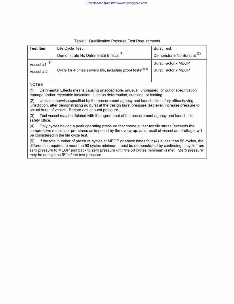
Table 1 Qualification Pressure Test Requirements
Test Item Life Cycle Test,
Demonstrate No Detrimental Effects (1)
Burst Test,
Demonstrate No Burst at (2)
Vessel #1 (3)
Vessel # 2
Cycle for 4 times service life, including proof tests.(4)(5)
Burst Factor x MEOP
Burst Factor x MEOP
NOTES (1) Detrimental Effects means causing unacceptable, unusual, unplanned, or out of specification damage and/or rejectable indication, such as deformation, cracking, or leaking. (2) Unless otherwise specified by the procurement agency and launch site safety office having jurisdiction, after demonstrating no burst at the design burst pressure test level, increase pressure to actual burst of vessel. Record actual burst pressure. (3) Test vessel may be deleted with the agreement of the procurement agency and launch site safety office. (4) Only cycles having a peak operating pressure that create a liner tensile stress (exceeds the compressive metal liner pre-stress as imposed by the overwrap, as a result of vessel autofrettage, will be considered in the life cycle test. (5) If the total number of pressure cycles at MEOP or above times four (4) is less than 50 cycles, the differences required to meet the 50 cycles minimum, must be demonstrated by continuing to cycle from zero pressure to MEOP and back to zero pressure until the 50 cycles minimum is met. “Zero pressure” may be as high as 5% of the test pressure.
Downloaded from http://www.everyspec.com
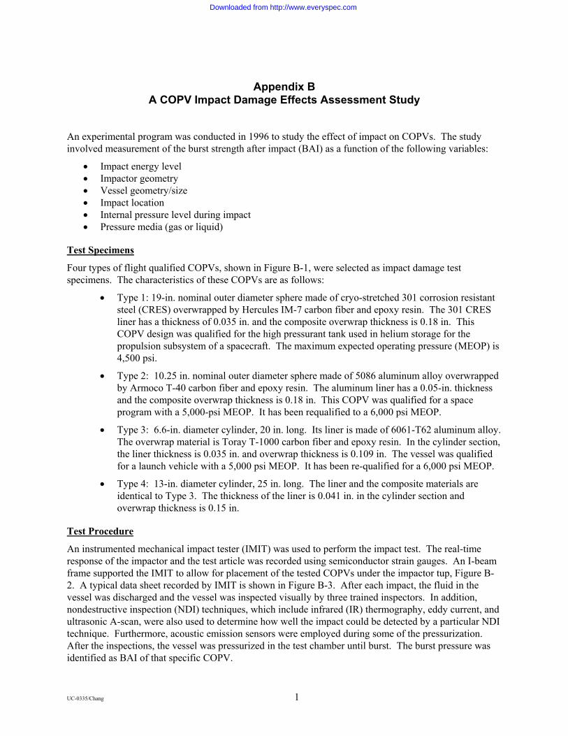
Appendix B
A COPV Impact Damage Effects Assessment Study
An experimental program was conducted in 1996 to study the effect of impact on COPVs. The study involved measurement of the burst strength after impact (BAI) as a function of the following variables:
• Impact energy level • Impactor geometry • Vessel geometry/size • Impact location • Internal pressure level during impact • Pressure media (gas or liquid)
Test Specimens
Four types of flight qualified COPVs, shown in Figure B-1, were selected as impact damage test specimens. The characteristics of these COPVs are as follows:
• Type 1: 19-in. nominal outer diameter sphere made of cryo-stretched 301 corrosion resistant steel (CRES) overwrapped by Hercules IM-7 carbon fiber and epoxy resin. The 301 CRES liner has a thickness of 0.035 in. and the composite overwrap thickness is 0.18 in. This COPV design was qualified for the high pressurant tank used in helium storage for the propulsion subsystem of a spacecraft. The maximum expected operating pressure (MEOP) is 4,500 psi.
• Type 2: 10.25 in. nominal outer diameter sphere made of 5086 aluminum alloy overwrapped by Armoco T-40 carbon fiber and epoxy resin. The aluminum liner has a 0.05-in. thickness and the composite overwrap thickness is 0.18 in. This COPV was qualified for a space program with a 5,000-psi MEOP. It has been requalified to a 6,000 psi MEOP.
• Type 3: 6.6-in. diameter cylinder, 20 in. long. Its liner is made of 6061-T62 aluminum alloy. The overwrap material is Toray T-1000 carbon fiber and epoxy resin. In the cylinder section, the liner thickness is 0.035 in. and overwrap thickness is 0.109 in. The vessel was qualified for a launch vehicle with a 5,000 psi MEOP. It has been re-qualified for a 6,000 psi MEOP.
• Type 4: 13-in. diameter cylinder, 25 in. long. The liner and the composite materials are identical to Type 3. The thickness of the liner is 0.041 in. in the cylinder section and overwrap thickness is 0.15 in.
Test Procedure
An instrumented mechanical impact tester (IMIT) was used to perform the impact test. The real-time response of the impactor and the test article was recorded using semiconductor strain gauges. An I-beam frame supported the IMIT to allow for placement of the tested COPVs under the impactor tup, Figure B-2. A typical data sheet recorded by IMIT is shown in Figure B-3. After each impact, the fluid in the vessel was discharged and the vessel was inspected visually by three trained inspectors. In addition, nondestructive inspection (NDI) techniques, which include infrared (IR) thermography, eddy current, and ultrasonic A-scan, were also used to determine how well the impact could be detected by a particular NDI technique. Furthermore, acoustic emission sensors were employed during some of the pressurization. After the inspections, the vessel was pressurized in the test chamber until burst. The burst pressure was identified as BAI of that specific COPV.
UC-0335/Chang 1
Downloaded from http://www.everyspec.com

Figure B-1. Four types of flight qualified COPVs used as impact test specimens.
UC-0335/Chang 2
Downloaded from http://www.everyspec.com
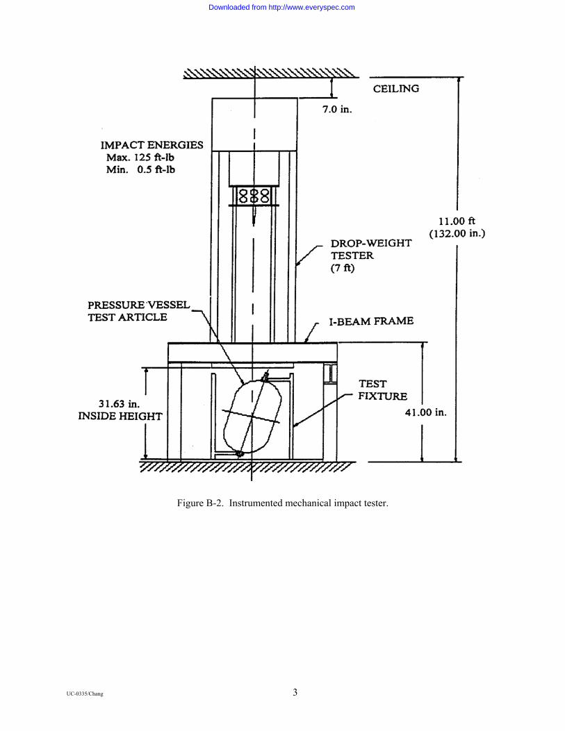
Figure B-2. Instrumented mechanical impact tester.
UC-0335/Chang 3
Downloaded from http://www.everyspec.com
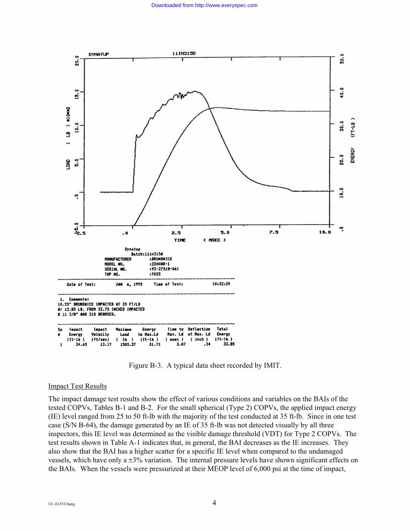
Figure B-3. A typical data sheet recorded by IMIT.
Impact Test Results
The impact damage test results show the effect of various conditions and variables on the BAIs of the tested COPVs, Tables B-1 and B-2. For the small spherical (Type 2) COPVs, the applied impact energy (IE) level ranged from 25 to 50 ft-lb with the majority of the test conducted at 35 ft-lb. Since in one test case (S/N B-64), the damage generated by an IE of 35 ft-lb was not detected visually by all three inspectors, this IE level was determined as the visible damage threshold (VDT) for Type 2 COPVs. The test results shown in Table A-1 indicates that, in general, the BAI decreases as the IE increases. They also show that the BAI has a higher scatter for a specific IE level when compared to the undamaged vessels, which have only a ±3% variation. The internal pressure levels have shown significant effects on the BAIs. When the vessels were pressurized at their MEOP level of 6,000 psi at the time of impact,
UC-0335/Chang 4
Downloaded from http://www.everyspec.com

BAIs were higher than those impacted while empty. The choice of pressurizing fluid, either gas or water, has no significant effect on the BAI.
Table B-1. Small Spherical (Type 2) COPVs Impact Test Results
S/N IE (ft-lb) Pressure Level at Impact (psi) and Test Fluid
BAI (psi) Degrad. % Remarks
B-77 B-58 B-57 B-61 B-62 B-69 B-64 B-73 B-72 B-70 B-84 B-85 B-68 B-96 B-71 B-81 B-82 B-83 B-86 B-78
25
25 35 35 35 35 35 35 35 35 35 35 35 35 35 35 35 35 40 50
Empty
Empty Empty Empty Empty Empty Empty Empty Empty Empty Empty Empty 6,500(W) 6,500(W) 6,500(W) 6,500(G) 6,500(G) 6,500(G) Empty Empty
11,106 10,243
8,4 7,1 7,8 8,9 8,7 9,2 9,8 8,1 9,1 8,8 9,9 9,9 9,4
10,496 9,2 9,3 8,1 7,3
>Baseline1
3 21 37 26 16 18 12 7 21 14 16 12 6 11 1 12 11 23 30
Impact @ boss/0.5 in. tup Norm Condition2 Norm Condition Norm Condition Impact @ Equater/0.5 in tup 1-in. tup 1-in. tup, not detected3 1-in. tup Norm Condition/50 cyc Norm Condition/50 cyc Norm Condition/50cyc Norm Condition Norm Condition Norm Condition Norm Condition Norm Condition Norm Condition Norm Condition Norm Condition Norm Condition
Nomenclature: BAI = burst strength after impact, IE = impact energy level, W = water, G = N2 gas. Notes: 1. Baseline burst strength of undamaged Type 2 vessels is 10,600 psi 2. Impacted at membrane section with 0.5-in. tup 3. One out of three inspectors missed visually
Table B-2 shows the impact test results for the small cylindrical (Type 3) COPVs; the IE level applied ranged from 5 to 20 ft-lb. The VDT was determined to be 15 ft-lb. At this IE level, the inspectors could not visually detect the damage sites of two test specimens (S/N S-08 and S-04). The most significant result is the effect of the pressure level during impact. When the cylindrical vessels were pressurized with water to 0.5xMEOP (3,000 psi) and then subjected to an impact at the VDT level (15 ft-lb), the BAIs (except S-08) were higher than those vessels that were empty during impact. The trend was the same (except B-72) as that observed in the small spherical COPV tests. However, when the water pressure was increased to MEOP (6,000 psi), the BAIs decreased significantly. The BAI decreased even more when gas, instead of water, was used as the pressurization fluid. At the VDT level (15 ft-lb), one test specimen (S/N S-33) exploded 0.7 sec after impact. The end result of the failure for this COPV was dramatic. Many loose pieces were found in the test chamber. Figure B-4 shows the vessel remnants from the impact test. Compared to the results of a typical hydraulic burst test, Figure B-5, the potential threat of an unexpected impact is obvious even for an unprotected COPV charged with gas during transportation or ground handling.
UC-0335/Chang 5
Downloaded from http://www.everyspec.com

Table B-2. Small Cylindrical (Type 3) COPVs Impact Test Results
S/N IE (ft-lb)
Pressure Level at Impact (psi) and
Test Fluid
BAI (psi) Degrad. % Remarks
S-18
S-06 S-32 S-05 S-30 S-08 S-20 S-13 S-09 S-04 S-29 S-22 S-38 S-31 S-33 S-37
5
10 15 15 15 15 20 15 15 15 15 15 15 15 15 15
Empty
Empty Empty Empty Empty Empty Empty 3,0004(W) 3,000(W) 3,000(W) 6,0005(W) 6,000(W) 6,000(W) 6,000(G) 6,000(G) 6,000(G)
9,800
8,884 8,246 8,377 9,257
10,123 7,764 9,892 9,425 9,776 7,510 7,950 8,877 7,569 N/A
7,724
81
17 23 22 14 5
28 8
12 9
30 26 17 29
N/A 28
Norm condition2
Norm condition Norm condition Norm condition Norm condition Impact @ transition3 Norm condition Norm condition Norm condition Norm condition6 Norm condition Norm condition Norm condition Norm condition Exploded7 Norm condition
Nomenclature: BAI = burst strength after impact, IE = impact energy level, W = water, G = N2 gas Notes: 1. Baseline burst strength of undamaged Type 3 vessels is 10,700 psi 2. Impact at membrane section with a 0.5-in. tup 3. One out of three inspectors missed damage visually 4. 0.5 x MEOP 5. MEOP 6. All three inspectors missed damage visually
Figure B-4. Vessel remnants after pneumatic burst at impact, Test S-33.
UC-0335/Chang 6
Downloaded from http://www.everyspec.com

Figure B-5. A typical COPV remnant after Hydroburst Test.
Impact test results for the large spherical (Type 1) and cylindrical (Type 4) COPVs are shown in Table B-3. It can be seen that, compared to the BAI of the small COPVs, the large cylindrical COPVs in general degrade more as the IE increases.
UC-0335/Chang 7
Downloaded from http://www.everyspec.com
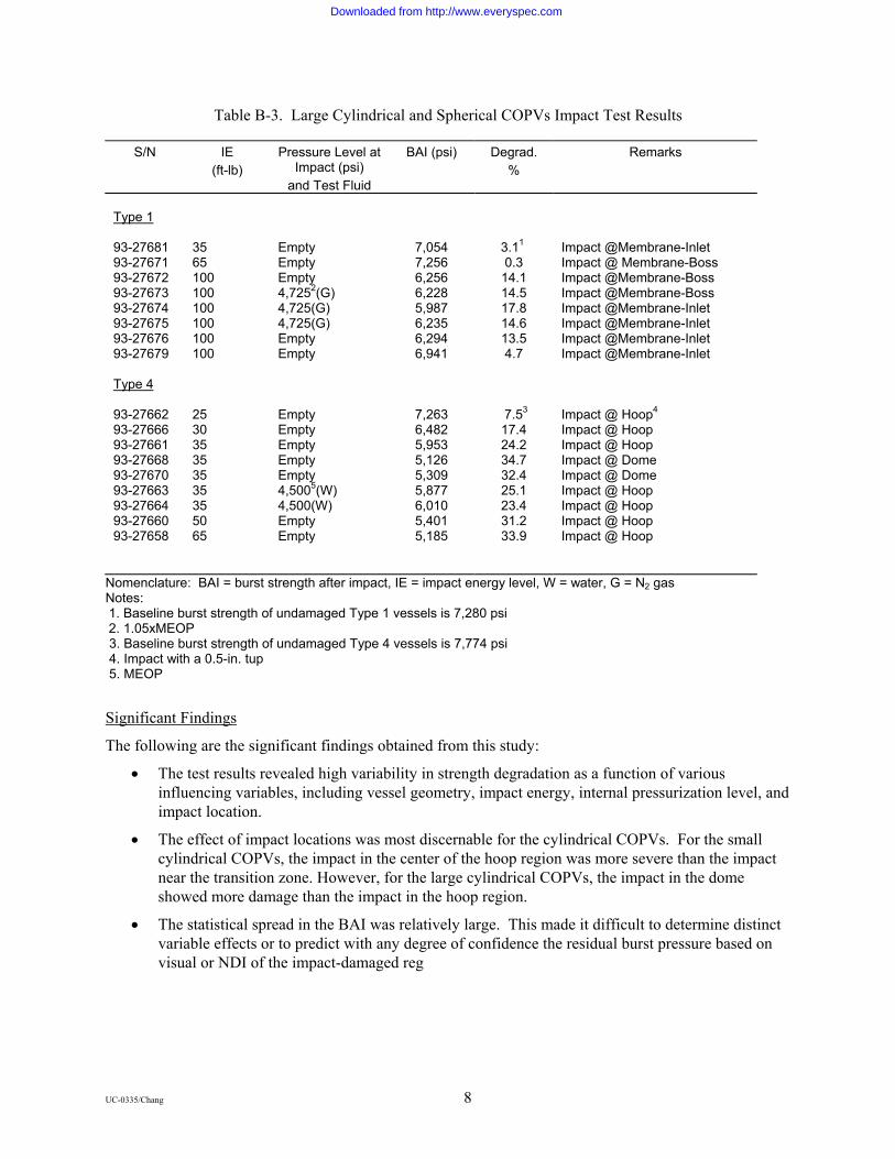
Table B-3. Large Cylindrical and Spherical COPVs Impact Test Results
S/N IE (ft-lb)
Pressure Level at Impact (psi)
and Test Fluid
BAI (psi) Degrad. %
Remarks
Type 1 93-27681 93-27671 93-27672 93-27673 93-27674 93-27675 93-27676 93-27679 Type 4 93-27662 93-27666 93-27661 93-27668 93-27670 93-27663 93-27664 93-27660 93-27658
35 65 100 100 100 100 100 100 25 30 35 35 35 35 35 50 65
Empty Empty Empty 4,7252(G) 4,725(G) 4,725(G) Empty Empty Empty Empty Empty Empty Empty 4,5005(W) 4,500(W) Empty Empty
7,054 7,256 6,256 6,228 5,987 6,235 6,294 6,941
7,263 6,482 5,953 5,126 5,309 5,877 6,010 5,401 5,185
3.11 0.3
14.1 14.5 17.8 14.6 13.5 4.7
7.53 17.4 24.2 34.7 32.4 25.1 23.4 31.2 33.9
Impact @Membrane-Inlet Impact @ Membrane-Boss Impact @Membrane-Boss Impact @Membrane-Boss Impact @Membrane-Inlet Impact @Membrane-Inlet Impact @Membrane-Inlet Impact @Membrane-Inlet Impact @ Hoop4 Impact @ Hoop Impact @ Hoop Impact @ Dome Impact @ Dome Impact @ Hoop Impact @ Hoop Impact @ Hoop Impact @ Hoop
Nomenclature: BAI = burst strength after impact, IE = impact energy level, W = water, G = N2 gas Notes: 1. Baseline burst strength of undamaged Type 1 vessels is 7,280 psi 2. 1.05xMEOP 3. Baseline burst strength of undamaged Type 4 vessels is 7,774 psi 4. Impact with a 0.5-in. tup 5. MEOP
Significant Findings
The following are the significant findings obtained from this study:
• The test results revealed high variability in strength degradation as a function of various influencing variables, including vessel geometry, impact energy, internal pressurization level, and impact location.
• The effect of impact locations was most discernable for the cylindrical COPVs. For the small cylindrical COPVs, the impact in the center of the hoop region was more severe than the impact near the transition zone. However, for the large cylindrical COPVs, the impact in the dome showed more damage than the impact in the hoop region.
• The statistical spread in the BAI was relatively large. This made it difficult to determine distinct variable effects or to predict with any degree of confidence the residual burst pressure based on visual or NDI of the impact-damaged reg
UC-0335/Chang 8
Downloaded from http://www.everyspec.com

Appendix C COPV Impact Damage NDI Techniques Assessment
Visual Inspection
The easiest for inspecting COPVs for mechanical damage is to perform a visual inspection. The outside of the COPV can be examined for signs of fiber damage using the unaided eyes. However, there is no quantitative reliability and confidence level associated with visual inspection capability. The impact energy level producing the damage state that cannot be detected by visual inspection is often called visual damage threshold (VDT).
The capability of visual inspection can be enhanced by the use of magnification loupes. The use of dye penetrant (or alcohol wipe) can sometimes accentuate indications. With a borescope, the inside liner of the COPV can be visually inspected for dents caused by impact. All these visual inspection techniques are hampered by any circumstances that limit visual access to the surface in question and by the poor surface contrast which typifies graphite/epoxy COPVs.
Ultrasonic Inspection
Ultrasonic inspection has been used in the aerospace industry for many years for detecting delamination or debonding for composite structures. Two ultrasonic techniques can be used for detecting mechanical damage including impact: through-transmission and pulse-echo. For the through-transmission technique, a sound pulse generated by one transducer is received by a second after passing completely through the pressure vessel. For the pulse-echo technique, a reflection rod is inserted into the center of the vessel. Figure C-1 shows a C-scan representation of a COPV after a 7.4 ft-lb impact. The impact left no visible indication on the surface of the COPV; the impact site can be clearly identified by the dark region in the scan.
Shearography
Electronic shearography is a noncontact interferometric method for measuring changes in the out of plane slope of a surface. The application of shearography to COPVs requires an initial image of the vessel to be acquired and stored in the digital memory of a computer. After storing the initial image, a small load is applied to the vessel. Best results can be achieved by pressurizing the vessel to some small amount of pressure. A second image of the loaded or slightly deformed vessel is acquired and subtracted from the initial image. The result is a family of high contrast fringes indicative of the deformation due to the pressure differential. Mechanical damage, such as impact to vessels, can cause subtle changes in load carrying characteristics and, hence, the contours of the vessel that are effectively detected using shearography.
The shearography inspection technique is particularly effective for detecting impact in the spherical COPVs because of the relatively uniform stress field, as shown in Figures C-2a and C-2b. The fringes presented in Figure C-2a represent the nominal deformation of a spherical COPV under 40-psi pressure These fringes can be contrasted with the fringes in Figure C-2b that clearly indicate the location of a 15 ft-lb impact where a 1-in. tup was employed.
A drawback to the use of the shearography in this application is the need for a matted surface to scatter the laser creating the necessary speckle pattern. During testing, the vessels might have to be prepared using either a strippable paint or a spray powder. However, this approach should be evaluated for a specific space application.
UC-0335/Chang 9
Downloaded from http://www.everyspec.com

Figure C-1. Pulse-echo C-scan of a COPV subjected to a 7.5 ft-lb. impact.
Thermography
Thermography is an NDE technique for measuring the surface temperature of an object based on the emission of infrared (IR) radiation. Using an IR camera, the complete temperature profile of a target can be recorded at video frame rates (30 Hz). Variation in the surface temperature profile can occur as the result of internal discontinuity of flaws within the hardware. Flaws that produce localized variation in the thermal properties of a composite, such as delamination or porosity, can often be easily detected via thermography.
For a COPV, one possible consequence of an impact event is the creation of a disbond between the liner and overwrap of the impact site. In the damage area, significantly high thermal impedance could be formed. An increase of thermal impendance translates into higher surface temperature when the COPV is exposed to a transient heat source. The location of surface hot spots can then be mapped using an IR camera. Evaluation of IR data showed a bruised area to be as much as 4oF hotter than surrounding areas shortly after transient heating with a quartz lamp. Images obtained during the thermography inspection of a cylindrical COPV with both 11 ft-lb and 25 ft-lb impact sites are shown in Figure C-3.
UC-0335/Chang 10
Downloaded from http://www.everyspec.com
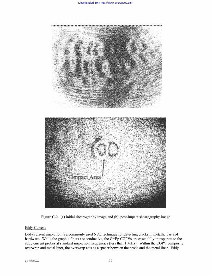
Figure C-2. (a) initial shearography image and (b) post-impact shearography image.
Eddy Current
Eddy current inspection is a commonly used NDE technique for detecting cracks in metallic parts of hardware. While the graphic fibers are conductive, the Gr/Ep COPVs are essentially transparent to the eddy current probes at standard inspection frequencies (less than 1 MHz). Within the COPV composite overwrap and metal liner, the overwrap acts as a spacer between the probe and the metal liner. Eddy
UC-0335/Chang 11
Downloaded from http://www.everyspec.com

currents that are very sensitive to the gap between the probe and the liner can be used to detect impact-induced dents in the liner. A simple eddy current image is shown in Figure C-4.
Figure C-3. Thermography indications on a COPV subjected to two impact levels.
Acoustic Emission
Loaded structures typically produce sound as the materials and components within the structure respond to the load. For composite hardware, matrix cracking or fiber breaking produces this sound. Acoustic emission (AE) monitoring is a method for evaluating the structural integrity of a structure based on the generation of sound during loading of the structure.
To detect impact damage that occurred in a COPV, the COPVs can be subjected to an initial AE screening and then pressurized again after being subjected to an impact. Changes in the acoustic activity can be noted with the COPV exhibiting significantly more AE after impact that exceeds a particular threshold. The energy threshold requires for AE monitoring to detect impact varied significantly between COPV types. Figure C-5 demonstrates the change activity that occurs after a 25 ft-lb impact on a cylindrical COPV.
UC-0335/Chang 12
Downloaded from http://www.everyspec.com
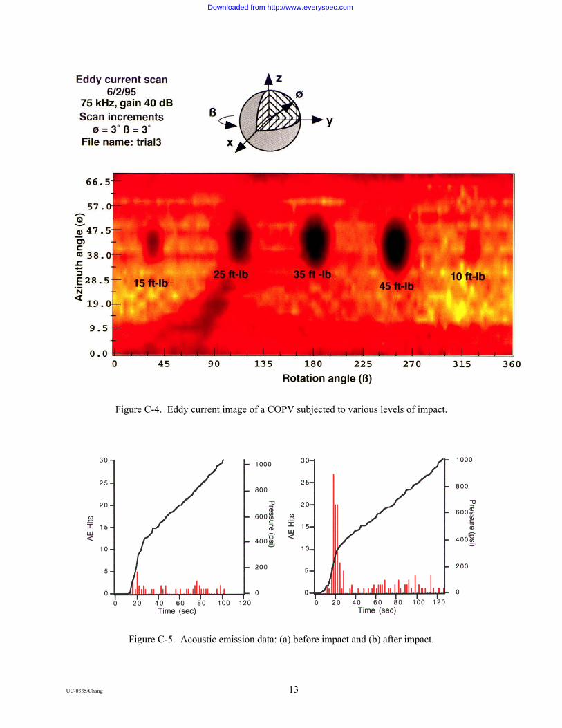
Figure C-4. Eddy current image of a COPV subjected to various levels of impact.
Figure C-5. Acoustic emission data: (a) before impact and (b) after impact.
UC-0335/Chang 13
Downloaded from http://www.everyspec.com

Summary
A number of NDE techniques have been shown to be effective for detecting impact damage sites of Gr/Ep COPVs even if the impact energy is below VDT. Selection of the most appropriate technique(s) depends on a number of factors including:
• Specific type (size, shape, material thickness, coatings, etc.) of COPV to be inspected
• Accessibility constraints during inspection
• Required sensitivity
A guide for selecting an appropriate technique is presented in Figure C-6. In the figure, “whole field” relates to how the data is taken, point-by-point as in a scan versus a whole field as in a grabbed image. “Flaw Characterization” is an assessment of how well the flaw is sized. “COPV preparation” includes what must be done to the COPV in order to be able to inspect it (coating the surface, etc.). “ Field Use” relates to how field deployable the technique is.
Figure C-6. Features of various NDE techniques for the inspection of Gr/Ep COPVs.
UC-0335/Chang 14
Downloaded from http://www.everyspec.com
Appendix D Proposed Impact Damage Control Plan
QA and NDI
A QA program, based on a comprehensive study and engineering requirements (e.g., drawings, material specifications, process specifications, workmanship standards, design review records, and fail mode analysis) of the COPV, should be established to assure that the necessary NDI and acceptance tests are effectively performed to verify that the flight article meets the requirements of this IDC Plan. The program should ensure that the COPVs conform to applicable drawings and process specifications; that no damage or degradation has occurred during material processing, fabrication, inspection, shipping, storage, operational use, and refurbishment; and that defects which could cause failure are detected or evaluated and corrected. As a minimum, the following considerations should be included in structuring the QA program.
Inspection Plan
An inspection plan should be established prior to the start of fabrication. The plan should specify appropriate inspection points and inspection techniques for use throughout the program, beginning with material procurement and continuing through fabrication, assembly, acceptance proof test, operation, and refurbishment, as appropriate. In establishing inspection points and inspection techniques, consideration should be given to the material characteristics, fabrication processes, design concepts, structural configuration, and accessibility for inspection of flaws.
Personnel Qualifications, Training, and Certifications
QA and NDE inspectors should be trained and certified in the visual recognition of impact damage to a COPV. For visual inspections, the inspectors should be trained to identify impact damage indentations, cuts, matrix cracking, delaminations, and fiber breakage on representative COPV surfaces prior to performing the required COPV inspection. In addition, the inspectors should also be trained to differentiate benign discontinuities (e.g., scuff marks, adhesive films, and superficial abrasions) from the detrimental defects listed above.
Personnel involved in specialized NDI should be trained in the application of the technique and data interpretation. Specialized training should be conducted using representative impact damage on COPVs. All personnel handling the COPV should familiar with handling procedures associated with space flight hardware. As a minimum, this should include training in the damage susceptibility of the COPV and methods of preventing potential impacts during handling.
Discrepancy reporting should be defined as part of the QA program and inspection plan procedures. Discrepancies in terms of impact damage, indications, overwrap or liner discontinuities, anomalies, or other flaws should be reported and dispositioned on approved forms. The jurisdictional authority should give approval prior to pressurizing the COPV to MEOP levels or above.
UC-0335/Chang 15
Downloaded from http://www.everyspec.com

QA SurveillancePersonnel Certification
TrainingQualification
Reject COPV
Flight Readiness Review
MRB
Accept COPV
Apply Accept/Reject Criteria
BAI PredictionAnalytical PredictionsTest Data Correlation
Perform NDIVisual Inspection
IR Thermography, UT A-Scan, EC ScanAE During Pressurization & Other Methods
Review Impact History
Assess BAI
Figure D-1. Assess BAI of COPV
Manufacturing Impact Damage Controls
Figure D-2 illustrates how the IDC Plan should be implemented during the manufacturing stage of the COPV. Handling procedures for manufacturing plant operations depend on the size of the COPV. For small cylindrical or spherical COPVs, manual handling should be accomplished with 100 percent QA surveillance using procedures that specify the use of gloves and foam pads to prevent scuffing of the composite overwrapped surface. For large COPVs, lifts and slings should be required to move the COPV. Prevention of COPV impact damage should be controlled procedurally with 100 percent QA surveillance when using lifts and slings.
Impact Control for Manufacturing Operations
Impact control for manufacturing operations should include the identification of tool impacts, floor drop conditions, and threat environments that could potentially contribute or cause COPV impact damage. Since impact protective covers may not be practical for all stages of COPV manufacturing operations, the plan basically requires that the IDC be implemented via procedural controls with 100 percent QA surveillance.
Tools in the IDC area of the manufacturing plants should be inventoried and controlled by the QA program. Tethered tools on lanyards should be required for any situation that potentially may result in the accidental dropping of tools that may strike the COPV throughout the manufacturing process. These
UC-0335/Chang 16
Downloaded from http://www.everyspec.com
processes include but should not be limited to filament winding, curing, autofrettage, leak testing, NDI, proof testing, and shipping preparation or storage.
Impact Control for Manufacturer’s Handling Operations
The IC should include handling procedures for protective covers or fixtures used during all stages of manufacturing. The handling procedures should identify the certification requirements for lifting items like slings, restraints, foam-padded chocks, fixtures, forklifts, or hoist assemblies.
Manual handling of the COPV should be performed in the manufacturing plants with the surveillance QA inspectors monitoring for any floor drops or transportation collisions that may occur during handling operations. Likewise, COPV transportation requiring forklift or hoist mechanical aids should be performed with a trained team of personnel to guide the COPV to avoid collision impacts with objects, walls, or floors.
Protective measures including impact protection covers, foam pads, foam-padded chocks, and foam-lined transportation containers should be used to reduce the likelihood of anomalies or discontinuities (e.g., scuff marks or light abrasions) associated with various handling operations.
Shipping Impact Damage Control
Figure D-3 illustrates the IDC Plan that should be implemented with respect to COPV shipping. Handling procedures for shipping and receiving depend on the size of the COPV. For small cylindrical or spherical COPVs, handling should be performed under 100 percent surveillance using procedures that specify the use of gloves and foam pads to prevent scuffing of the composite overwrapped surface. For large COPVs, lifts and slings should be required to move the COPV. Prevention of COPV impact damage should be controlled procedurally when using lifts and slings.
Shipping Container Design
Transportation containers should be designed to protect the COPV from the threat environments encountered during shipping without inflicting damage to the COPV. For small spherical COPVs, the shipping container should be foam lined per MIL–PRF–26514. Sufficient foam thickness is required to prevent COPV damage resulting from shipping container drops or collision impacts to the shipping container structure. The shock case defined by FED–STD 101, Method 5007.1, Level B should be used to design the shipping container. Frequently, larger or cylindrical COPV containers are suspended on foam chocks or foam-lined saddle fixtures. American Society for Testing and Materials (ASTM) D 1974–91 provides standard practice for closing, sealing, and reinforcing fiberboard shipping containers.
Shipping containers with multiple compartments should be permitted for the shipment of a plurality of small COPVs, but each compartment should be individually lined with sufficient foam to preclude impact damage during shipment. The entire crate should be designed to survive a drop from a height consistent with the threat environment (minimum 4 ft.) without inflicting damage to the COPV.
UC-0335/Chang 17
Downloaded from http://www.everyspec.com
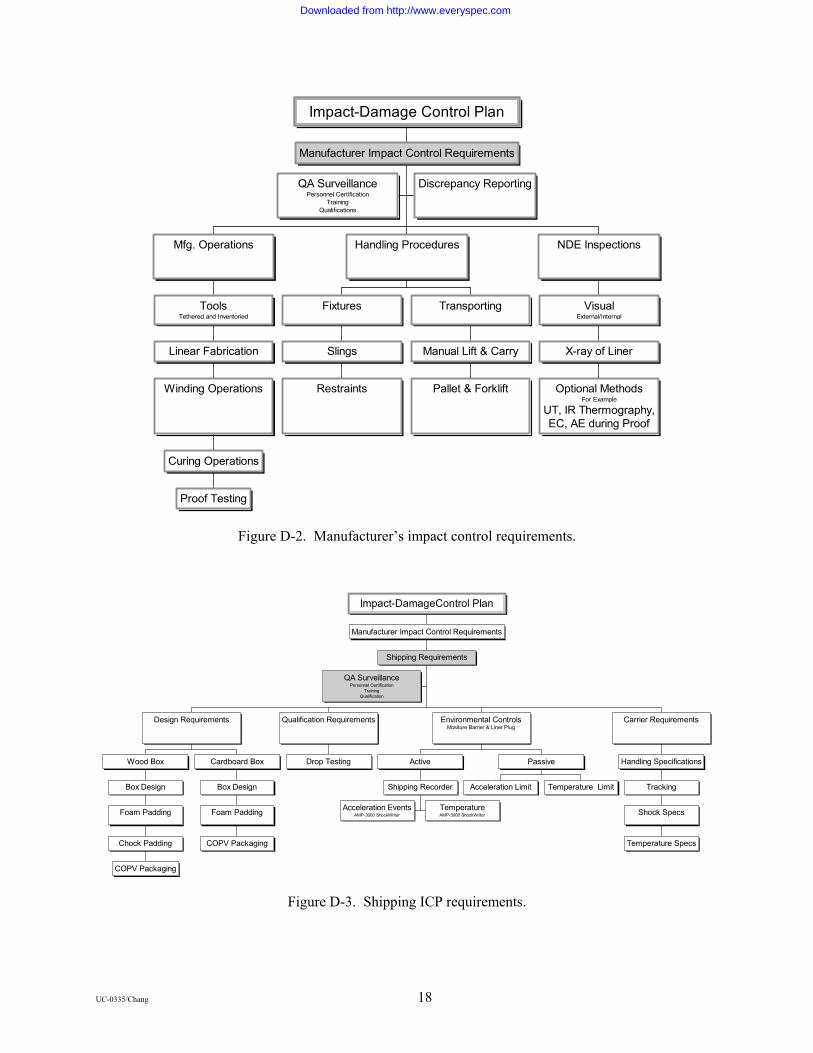
QA SurveillancePersonnel Certification
TrainingQualifications
Discrepancy Reporting
Proof Testing
Curing Operations
Winding Operations
Linear Fabrication
ToolsTethered and Inventoried
Mfg. Operations
Restraints
Slings
Fixtures
Pallet & Forklift
Manual Lift & Carry
Transporting
Handling Procedures
Optional MethodsFor Example
UT, IR Thermography,EC, AE during Proof
X-ray of Liner
VisualExternal/Internal
NDE Inspections
Manufacturer Impact Control Requirements
Impact-Damage Control Plan
Figure D-2. Manufacturer’s impact control requirements.
QA SurveillancePersonnel Certification
TrainingQualification
COPV Packaging
Chock Padding
Foam Padding
Box Design
Wood Box
COPV Packaging
Foam Padding
Box Design
Cardboard Box
Design Requirements
Drop Testing
Qualification Requirements
Acceleration EventsAMP-3000 ShockWriter
TemperatureAMP-3000 ShockWriter
Shipping Recorder
Active
Acceleration Limit Temperature Limit
Passive
Environmental ControlsMositure Barrier & Liner Plug
Temperature Specs
Shock Specs
Tracking
Handling Specifications
Carrier Requirements
Shipping Requirements
Manufacturer Impact Control Requirements
Impact-DamageControl Plan
Figure D-3. Shipping ICP requirements.
UC-0335/Chang 18
Downloaded from http://www.everyspec.com
For large COPVs, shipping containers should be constructed to survive a minimum (4-ft.) drop while protecting the COPV. This includes suspending the COPV in foam pads, chocks, or saddles. The lid of the shipping container should be secured with metal clamps held in place with banding straps. The thickness of foam required to preclude COPV damage depends on the size and weight of the COPV. Small vessels may require only I-in. thick foam, while the large vessels require foam pads up to 6-in. thick or greater. The foam lining specification should be in accordance with MIL–PRF–26514. ASTM D 1083–88 provides standard test methods for handling shipping cases and crates.
Shipping Container Qualification Testing
If the shipping container cannot be qualified by similarity to a previously qualified design, the new container design should be subjected to drop testing from a height consistent with the threat environment (minimum 4 ft.), with the COPV installed. The results of these drop tests should demonstrate that the BAI of the COPV does not degrade to below its design burst strength. ASTM D 775-80 provides standard guidelines for drop testing loaded boxes, while ASTM D 4169-90 provides standard guidelines for performance testing of shipping containers and systems.
Shipping Container and Environmental Controls
The shipping container should be designed to protect the COPV from environmental factors that may degrade the performance of the COPV. The COPV should be sealed in a moisture barrier with an independent port boss seal that protects both the COPV overwrap and the liner from environmental exposure to high humidity environments or from corrosive airborne contaminants during shipping and handling. Desiccants should be permitted, provided the chemical materials are compatible with the COPV overwrap and liner. ASTM D 895–79 provides a standard test method for measuring the water vapor permeability of packages.
The shipping container may also be equipped with active or passive acceleration and temperature recording devices to monitor the environmental shock conditions and temperature conditions during shipment. In situ health monitoring of shipping containers can be implemented with both passive and active devices. Passive monitors include shock–sensitive indicators that unload a configuration of spring-loaded balls or shock-sensitive strips that change color when the indicator has been subjected to a shock event. Active monitors include units like the AMP-3000 Shockwriter with the capability of storing up to several hundred events logged over a shipping duration up to 90 days.
COPV Shipping Carrier Requirements
The shipping carrier should be qualified to ship and handle flight hardware. The shipping and handling documents should specify the acceptable ranges and limits with respect to shock, impact sensitivity, and temperature. The COPV cargo should be tracked throughout all stages of the shipping process.
COPV Receiving Inspection Requirements
Figure D-4 illustrates the ICP that should be implemented with respect to COPV receiving inspection requirements. Handling procedures for receiving inspection depend on the size of the COPV. For small cylindrical or spherical COPVs, manual handling should be accomplished with 100 percent QA surveillance using procedures that specify the use of gloves and foam pads to prevent scuffing of the composite overwrapped surface. For large COPVs, lifts and slings should be required to move the COPV. Prevention of COPV impact damage should be controlled procedurally with 100 percent QA surveillance when using lifts and slings.
UC-0335/Chang 19
Downloaded from http://www.everyspec.com

QA SurveillancePersonnel Certification
TrainingQualification
Mfg. Logbook
Mfg. NDE Data
Pedigree Review
Environmental DataShock and Temperature Levels
Visual Damage
Shipping Container
Other as RequiredFor Example
IR ThermographyX-ray of Liner
VisualExternal/Internal Inspections
NDE Inspection
Access Controls
Environmental Controls
Bonded Stores
Receiving Inspection Requirements
Shipping Requirements
Manufacturer Impact Control Requirements
Impact Control Plan
Figure D-4. Receiving inspection ICP requirements.
COPV receiving inspections should be performed to assess the integrity of the COPV as received. These inspections should include a visual inspection of the composite overwrap, a visual inspection of the COPV liner using a borescope, and an X–ray radiographic inspection of the metal liner.
Review of Pedigree Information
Pedigree information, shipped with the COPV, should be reviewed as part of the receiving inspection process to ensure that the COPV meets the program requirements. Manufacturer’s NDE data should be reviewed and compared to procurement agency requirements for the COPV and the receiving inspection NDE records. The manufacturer’s COPV logbook should be reviewed to determine if any suspect impact damage conditions have been reported.
Shipping Container Inspections
Visual inspection of the shipping container should be performed to determine if there are indications of a drop during shipment. Shipping container damage indications include crushed corners or impact indentations on the external surface. Internally, unusual foam deformation or compaction will provide clues of potential damage from shipping container drops.
If the shipping container is equipped with active or passive shock and/or temperature monitors, data from these units should be used to assess the environmental conditions during shipment of the COPV.
Bonded Stores
All COPVs not installed on spacecraft or launch vehicle hardware should be stored in a Bonded Stores facility with access controls defined by the program QA requirements. The Bonded Stores facilities
UC-0335/Chang 20
Downloaded from http://www.everyspec.com

should have environmental controls to maintain the COPV within the required temperature and humidity specifications.
Installation and System–Level Impact Control
Figure D-1 illustrates the ICP overview that should be implemented during the installation and system–level operations of the COPV mounted on the spacecraft hardware or the launch vehicle. COPV handling procedures for the spacecraft or launch vehicle installation and test phase depend on the size of the COPV. For small cylindrical or spherical COPVs, manual handling should scuffing of the composite overwrapped surface. For large COPVs, lifts and slings should be required to move the COPV. Prevention of COPV impact damage should be controlled procedurally with 100 percent QA surveillance when using lifts and slings.
Installation & Test Procedure Requirements
QA SurveillancePersonnel Certification
TrainingQualification
Inventoried Tools 100% QA Surveillance
Tethered Tools Scuff Protectors
Proximity Torquing Procedures Periodic Visual Inspections
Authorized & Controlled AccessImpact Caution Signs
Procedures -- Unpressurized COPV
Inventoried Tools 100% QA Surveillance
Tethered Tools Scuff Protectors
Proximity Torquing Procedures Periodic Visual Inspections
Authorized & Controlled AccessHazard Warning Signs
< MEOP/10
Tool Activity Within ProximityRequires Mandatory
Impact Protector Devices
PressurizationApproval Required byJurisdictional Authority
Authorized & Restricted AccessHazard Danger Signs
MEOP/10 < P </= MEOP
Procedures -- Pressurized COPV
Procedural Only
Receiving Inspection Requirements
Shipping Requirements
Manufacturer Impact Control Requirements
Impact Control Plan
Figure D-5. Installation and system–level procedures for procedural only ICP.
ICP by Procedure Only
Figure D-5 illustrates the procedural only ICP option that, if selected, should be used during the installation and test of the COPV mounted on the spacecraft hardware or the launch vehicle. Handling procedures for installation depend on the size of the COPV. For small COPV cylindrical or spherical vessels, manual handling should be accomplished using procedures that specify the use of gloves and foam pads to prevent scuffing of the composite overwrapped surface. For large COPVs, lifts and slings should be required to move the COPV. Prevention of COPV impact damage should be controlled procedurally when using lifts and slings.
Procedures for Unpressurized COPV
UC-0335/Chang 21
Downloaded from http://www.everyspec.com
ICP procedures for unpressurized COPVs should require access control and authorization by the jurisdictional authority for personnel to work within close proximity to the COPV and should be performed with 100 percent QA surveillance. Caution signs should be displayed near the COPV to make personnel aware of the impact sensitivity. Inventoried and tethered tools should be required when this work is performed.
Torque or leverage tool operations within close proximity to the COPV should be performed under procedural control with 100 percent QA surveillance.
Scuff–protective materials in the form of high–density Ensolite®1 foam or equivalent should be used to reduce the potential for false impact indications resulting from small tool scuffs and abrasions. Period inspections by trained and certified NDE inspectors should be performed prior to the installation of scuff–protective materials and after the removal thereof.
Procedures for Pressurized COPV
Access control for working in close proximity to a pressurized COPV (< MEOP/10) should be controlled and authorized by the jurisdictional authority. Hazard Warning signs shall be displayed near the COPV to warn personnel of the impact sensitivity and the potential burst hazard of the COPV. ICP procedures for COPV pressurized to < MEOP/10 should require inventoried and tethered tools.
Torque or leverage tool operations within close proximity to the COPV should be performed under procedural control with 100 percent QA surveillance.
Scuff–protective materials in the form of high–density Ensolite foam or equivalent should be used to reduce the potential for false positive impact indications resulting from small tool scuffs and abrasions. Period inspections by trained and certified NDE inspectors should be performed prior to the installation of scuff-protective materials and after the removal thereof.
Pressurization of a COPV from 0.1x MEOP to MEOP or above should require authorization by the jurisdictional authority and personnel access should be restricted. Hazard Danger signs should be displayed near the COPV to warn personnel of impact sensitivity and the potential for catastrophic burst. In addition, any tool activity performed within proximity to the pressurized COPV should require mandatory impact protector devices to be used.
ICP Implemented with Impact Indicators
Figure C-6 illustrates the impact indicator ICP option that, if selected, should be implemented during the installation and test of the COPV mounted on the spacecraft hardware or the launch vehicle. Handling procedures for installation depend on the size of the COPV. For small cylindrical or spherical COPVs, manual handling should be accomplished using procedures that specify the use of gloves and foam pads to prevent scuffing of the composite overwrapped surface. For large COPVs, lifts and slings should be required to move the COPV. Prevention of COPV impact damage should be controlled procedurally when using lifts and slings.
Design Requirements for Impact Indicators
Impact indicators should be capable of detecting any impact condition that could result in a 5 percent or greater degradation of COPV nominal burst strength. Piezoresistive film, commonly used as strain and force sensors, sandwiched between two 0.25-in. thick high–density Ensolite foam layers provides an excellent active impact indicator with impact force discrimination. By using an electrical comparator
1 Ensolite® is a registered trademark of Ensolite.
UC-0335/Chang 22
Downloaded from http://www.everyspec.com
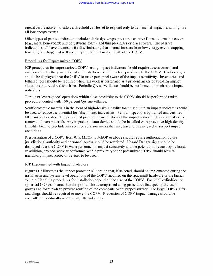
circuit on the active indicator, a threshold can be set to respond only to detrimental impacts and to ignore all low energy events.
Other types of passive indicators include bubble dye wraps, pressure-sensitive films, deformable covers (e.g., metal honeycomb and polystyrene foam), and thin plexiglass or glass covers. The passive indicators shall have the means for discriminating detrimental impacts from low energy events (tapping, touching, scuffing) that will not compromise the burst strength of the COPV.
Procedures for Unpressurized COPV
ICP procedures for unpressurized COPVs using impact indicators should require access control and authorization by the jurisdictional authority to work within close proximity to the COPV. Caution signs should be displayed near the COPV to make personnel aware of the impact sensitivity. Inventoried and tethered tools should be required when this work is performed as a prudent means of avoiding impact situations that require disposition. Periodic QA surveillance should be performed to monitor the impact indicators.
Torque or leverage tool operations within close proximity to the COPV should be performed under procedural control with 100 percent QA surveillance.
Scuff-protective materials in the form of high-density Ensolite foam used with an impact indicator should be used to reduce the potential for false impact indications. Period inspections by trained and certified NDE inspectors should be performed prior to the installation of the impact indicator device and after the removal of such materials. Any impact indicator device should be installed with protective high-density Ensolite foam to preclude any scuff or abrasion marks that may have to be analyzed as suspect impact conditions.
Pressurization of a COPV from 0.1x MEOP to MEOP or above should require authorization by the jurisdictional authority and personnel access should be restricted. Hazard Danger signs should be displayed near the COPV to warn personnel of impact sensitivity and the potential for catastrophic burst. In addition, any tool activity performed within proximity to the pressurized COPV should require mandatory impact protector devices to be used.
ICP Implemented with Impact Protectors
Figure D-7 illustrates the impact protector ICP option that, if selected, should be implemented during the installation and system-level operations of the COPV mounted on the spacecraft hardware or the launch vehicle. Handling procedures for installation depend on the size of the COPV. For small cylindrical or spherical COPVs, manual handling should be accomplished using procedures that specify the use of gloves and foam pads to prevent scuffing of the composite overwrapped surface. For large COPVs, lifts and slings should be required to move the COPV. Prevention of COPV impact damage should be controlled procedurally when using lifts and slings.
UC-0335/Chang 23
Downloaded from http://www.everyspec.com

Installation & Test Procedure Requirements
QA SurveillancePersonnel Certification
TrainingQualification
Inventoried Tools Periodic QA Surveillance
Tethered Tools Deploy Indicator
Proximity Torquing Procedures Periodic Visual Inspections
Authorized & Controlled AccessImpact Caution Signs
Procedures -- Unpressurized COPV
Inventoried Tools Periodic QA Surveillance
Tethered Tools Deploy Indicator
Proximity Torquing Procedures Periodic Visual Inspections
Authorized & Controlled AccessHazard Warning Signs
< MEOP/10
Tool Activity Within ProximityRequires Mandatory
Impactor Protector Devices
PressurizationApproval Required byJurisdictional Authority
Authorized & Restricted AccessHazard Danger Signs
MEOP/10 < P </= MEOP
Procedures -- Pressurized COPV
Impact IndicatorsActive or Passive
Receiving Inspection Requirements
Shipping Requirements
Manufacturer Impact Control Requirements
Impact Control Plan
Figure D-6. Installation and system–level procedure for using impact indicators ICP.
Design Requirements for Impact Protectors
Impact protectors should be capable of shielding a COPV from impact damage consistent with the threat environment or at least up to the load limits for the integral boss and mounting fixtures. An impact inflicting any damage that potentially degrades the burst strength of the COPV more than 5 percent from its nominal burst pressure is unacceptable.
The minimum design cross-section of an impact protector cover shall include the shielding layers depicted in Figure D-8. The indentation damage from a credible impact should be completely absorbed by a hard shell fabricated from fiberglass epoxy, Kevlar2 epoxy, or equivalent material that is sufficiently thick to absorb the indentation energy without penetration. The potential deflection damage should be mitigated by spreading the peak loading transmitted through the hard shell over an area consistent with the dimensions of the COPV. Deflection damage should be further mitigated by introducing an energy-absorbing material between the hard shell and the COPV. Aluminum mesh foam (20 pores per inch, 0.5-in. thick), manufactured by ERG Materials, Inc., is an example of energy-absorbing material that has been qualified for this application. Other materials with equivalent energy-absorbing properties can be
2 Kevlar® is a registered trademark of E. I. DuPont deNemours and Company.
UC-0335/Chang 24
Downloaded from http://www.everyspec.com
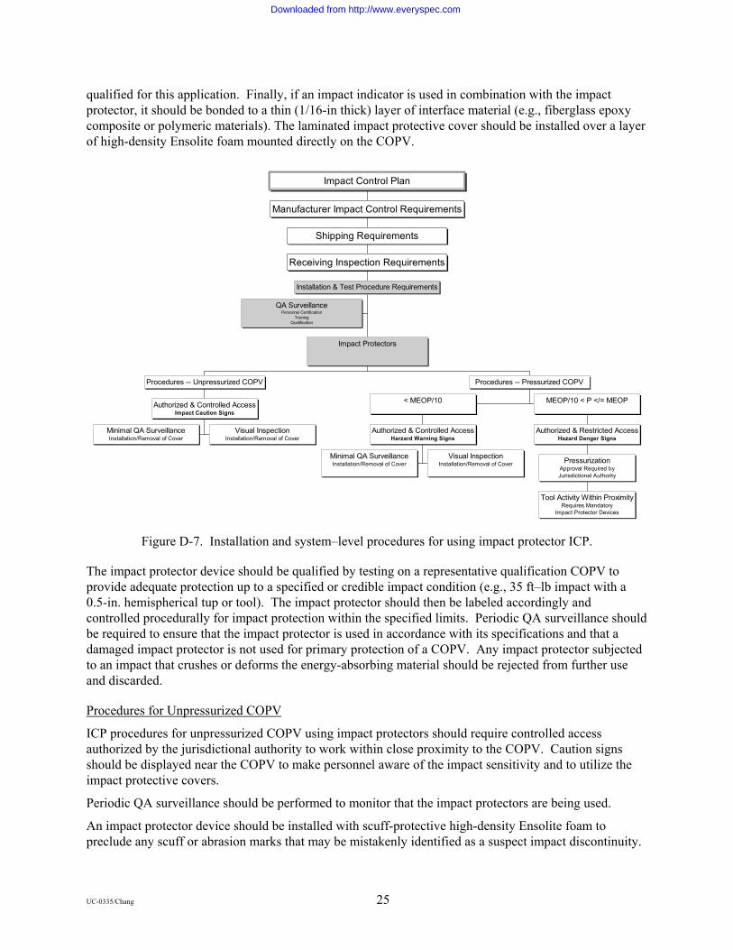
qualified for this application. Finally, if an impact indicator is used in combination with the impact protector, it should be bonded to a thin (1/16-in thick) layer of interface material (e.g., fiberglass epoxy composite or polymeric materials). The laminated impact protective cover should be installed over a layer of high-density Ensolite foam mounted directly on the COPV.
Installation & Test Procedure Requirements
QA SurveillancePersonnel Certification
TrainingQualification
Minimal QA SurveillanceInstallation/Removal of Cover
Visual InspectionInstallation/Removal of Cover
Authorized & Controlled AccessImpact Caution Signs
Procedures -- Unpressurized COPV
Minimal QA SurveillanceInstallation/Removal of Cover
Visual InspectionInstallation/Removal of Cover
Authorized & Controlled AccessHarzard Warning Signs
< MEOP/10
Tool Activity Within ProximityRequires Mandatory
Impact Protector Devices
PressurizationApproval Required byJurisdictional Authority
Authorized & Restricted AccessHazard Danger Signs
MEOP/10 < P </= MEOP
Procedures -- Pressurized COPV
Impact Protectors
Receiving Inspection Requirements
Shipping Requirements
Manufacturer Impact Control Requirements
Impact Control Plan
Figure D-7. Installation and system–level procedures for using impact protector ICP.
The impact protector device should be qualified by testing on a representative qualification COPV to provide adequate protection up to a specified or credible impact condition (e.g., 35 ft–lb impact with a 0.5-in. hemispherical tup or tool). The impact protector should then be labeled accordingly and controlled procedurally for impact protection within the specified limits. Periodic QA surveillance should be required to ensure that the impact protector is used in accordance with its specifications and that a damaged impact protector is not used for primary protection of a COPV. Any impact protector subjected to an impact that crushes or deforms the energy-absorbing material should be rejected from further use and discarded.
Procedures for Unpressurized COPV
ICP procedures for unpressurized COPV using impact protectors should require controlled access authorized by the jurisdictional authority to work within close proximity to the COPV. Caution signs should be displayed near the COPV to make personnel aware of the impact sensitivity and to utilize the impact protective covers.
Periodic QA surveillance should be performed to monitor that the impact protectors are being used.
An impact protector device should be installed with scuff-protective high-density Ensolite foam to preclude any scuff or abrasion marks that may be mistakenly identified as a suspect impact discontinuity.
UC-0335/Chang 25
Downloaded from http://www.everyspec.com

Period inspections by trained and certified NDE inspectors should be performed prior to the installation of the impact protector device and after the removal of such materials.
Figure D-8. Cross–section of COPV impact protector.
Procedures for Pressurized COPV
Access control for working in close proximity to a COPV pressurized below MEOP should be controlled and authorized by the jurisdictional authority. Hazard Warning signs should be displayed near the COPV to warn personnel of the impact sensitivity and the potential burst hazard of the COPV.
Scuff-protective materials in the form of high-density Ensolite foam (either used directly as part of the impact protector or as additional scuff protection measures) should be used to reduce the potential for false impact indications. Period inspections by trained and certified NDE inspectors should be performed prior to the installation of scuff-protective materials and after the removal thereof.
Pressurization of a COPV from 0.1x MEOP to MEOP or above should require authorization by the jurisdictional authority and personnel access should be restricted. Hazard Danger signs should be displayed near the COPV to warn personnel of impact sensitivity and the potential for catastrophic burst.
UC-0335/Chang 26
Downloaded from http://www.everyspec.com

In addition, any tool activity performed within proximity to the pressurized COPV should require mandatory impact protector devices to be used.
UC-0335/Chang 27
Downloaded from http://www.everyspec.com

INTERNAL DISTRIBUTION LIST REPORT TITLE
Implementation Guidelines for ANSI/AIAA S-081; Space Systems-Composite Overwrapped Pressure Vessels
REPORT NO. PUBLICATION DATE SECURITY CLASSIFICATION TOR-2001(8504)-1 April 2001 Unclassified
1. FOR OFF-SITE PERSONNEL, SHOW LOCATION SYMBOL, e.g., JOHN Q. PUBLIC/VAFB
2. IF LISTS IS ALTERED, INITIAL CHANGE(S) AND SHOW AFFILIATION *FOR SECRET REPORTS SHOW BLDG AND ROOM, NOT MAIL STATION
NAME (Include Initials) MAIL CODE* NAME (Include Initials) MAIL CODE*
FINAL APPROVER DRAW LINE(S) ACROSS UNFILLED SPACE AND INITIAL TO PRECLUDE ADDITIONS
M. Aswani M4-920 J. B. Chang M4-912 H. C. Chen M4-912 M. C. Chen M4-912 J. K. Chi M4-920 S. T. Chiu M4-912 S. K. Chu M1-122 R. Crespo VAFB R. J. De Lorenzo M8-717 T. T. Do M4-910 L. R. Drake M1-131 G. Epstein M4-919 S. Goldstein M4-910 W. H. Goodman M5-564 C. S. Gran M4-967 E. K. Hall, II M4-920 J. Ingram-Cotton M5-565 R. A. Jamieson C/CANAVERAL R. F. Johnson M5-579 E. C. Johnson M2-248 W. H. Kao M2-242 H. A. Katzman M2-248 J. C. Klug M4-920 D. R. Langley C/CANAVERAL A. C. Liang M4-945 S. R. Lin M4-912 D. A. Love M4-923 N. E. Martino M4-912
J. Meltzer M5-565 K. R. Morrison CH2-307 G. F. Mueller M1-132 J. P. Nokes M2-248 N. R. Patel M4-899 E. R. Scheyhing M4-899 G. L. Steckel M2-242 D. G. Sutton M2-248 B. H. Wendler M4-907 W. M. Zelinsky C/CANAVERAL
APPROVED ________________________________________________________________________________________________ DATE _____________________
IF LIST COMPRISES TWO OR MORE SHEETS, COMPLETE ABOVE BLOCK ON LAST SHEET ONLY SHEET 1 OF 1 A E R O S P A C E F O R M 2 3 9 4 R E V 3 - 8 5
Downloaded from http://www.everyspec.com

EXTERNAL DISTRIBUTION LIST REPORT TITLE
Implementation Guidelines for ANSI/AIAA S-081; Space Systems-Composite Overwrapped Pressure Vessels
REPORT NO. PUBLICATION DATE SECURITY CLASSIFICATION
SH
TOR-2001(8504)-1 April 2001 Unclassified
MILITARY AND GOVERNMENT OFFICES ASSOCIATE CONTRACTORS AND OTHERS 1. SHOW FULL MAILING ADDRESS: INCLUDE ZIP CODE, MILITARY OFFICE SYMBOL, AND “ATTENTION” LINE. 2. IF LIST IS ALTERED, INITIAL CHANGE(S) AND OW AFFILIATION.
FINAL APPROVER DRAW LINE(S) ACROSS UNFILLED SPACE AND INITIAL TO PRECLUDE ADDITIONS DISTRIBUTION LIMITATIONS MARKED ON THE COVER/TITLE PAGE ARE AUTHORIZED BY SIGNATURE BELOW
SMC
Col. Fitzgerald AX Dr. Huang AXZ Patrick AFB Cocoa Beach, FL 32925 Attn: Mr. Taddy
APPROVED ________________________________________________________________________________________________ DATE _____________________ (AEROSPACE) APPROVED BY _____________________________________________________________________________________________ DATE _____________________ (AF OFFICE) (NOT REQUIRED FOR ATR CATEGORY)
IF LIST COMPRISES TWO OR MORE SHEETS, COMPLETE ABOVE BLOCK ON LAST SHEET ONLY SHEET 1 OF 1 A E R O S P A C E F O R M 2 3 8 0 R E V 1 1 - 8 5
Downloaded from http://www.everyspec.com