implementation of a beamline for fast xafs/xrd … of a beamline for fast xafs/xrd experiments josé...
TRANSCRIPT

Chemistry Department
Implementation of a beamline for fast XAFS/XRD experiments
José A. Rodriguez
* Collaborators: Synchrotron Catalysis ConsortiumBNL: J. HansonYeshiva University: A. FrenkelUniv of Delaware: J. ChenUOP: S. BareORNL: D. MullinsPNNL: C. PedenNSLS: S. Hulbert
Outline
• In-situ time-resolved X-ray diffraction at NSLS
• Quick XAFS at NSLS
• Need for simultaneous XRD and XAFS
• Projected XRD/XAFS beamline at NSLS-II
2002 BESAC workshop Opportunities in Catalysis in the21st Century: “The Grand Challenge for catalysis scienceIn the 21st century is to understand how to design catalyststructures to control catalytic activity and selectivity.”
To meet this challenge, techniques for the characterizationof catalysts in-situ, as they evolve in time, are necessary.

In situ Time-resolved X-ray Diffraction:
Experiments at BNL have shown that it is feasible to conduct subminute, time-resolved XRD experiments (-190 C < T < 900 C; P < 45 atm)
Norby and Hanson, Catal. Today 39 (1998) 301Rodriguez and Hanson, Ciencia, 14 (2006) 177
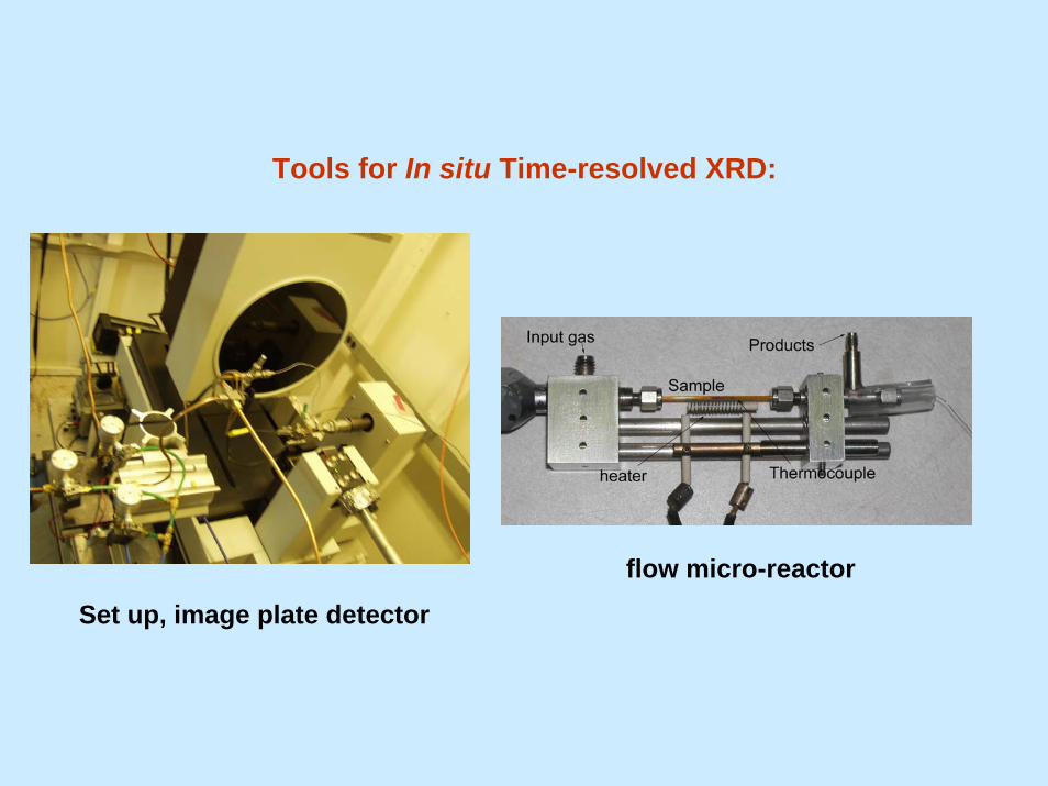
Tools for In situ Time-resolved XRD:
Set up, image plate detector
flow micro-reactor
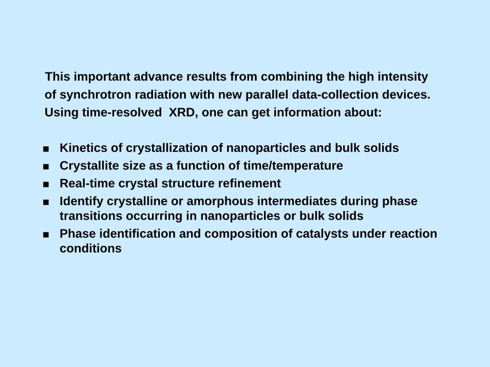
This important advance results from combining the high intensityof synchrotron radiation with new parallel data-collection devices. Using time-resolved XRD, one can get information about:
Kinetics of crystallization of nanoparticles and bulk solids Crystallite size as a function of time/temperatureReal-time crystal structure refinementIdentify crystalline or amorphous intermediates during phase transitions occurring in nanoparticles or bulk solidsPhase identification and composition of catalysts under reactionconditions

Synthesis of a Ni2P/SiO2 catalyst: Time-resolved XRD studies
A nickel phosphate precursor is reduced in a flow of hydrogen/thiophene
Ni2P
Ni12P5
Ni2P
Rodriguez et al, J. Phys Chem. B 107 (2003) 6276
Temperature (oC)
0 200 400 600 800
HD
S ac
tivity
NiPOx
Ni12P5
Ni2P
2θ
Tim
e / h
CuCeO2
CuO
200oC300oC
400oC500oC
2θ
Tim
e / h
CuCeO2
CuO
2θ
Tim
e / h
CuCeO2
CuO
200oC300oC
400oC500oC
0 2 4 6 8 10 12 14
200oC 500oC
300oC400oC
300oC
400oC300oC
500oC400oC
CuO
Cu0.2Ce0.8O2
H2 r
elat
ive
conc
entra
ion
Time / hour
5%Cu/CeO2
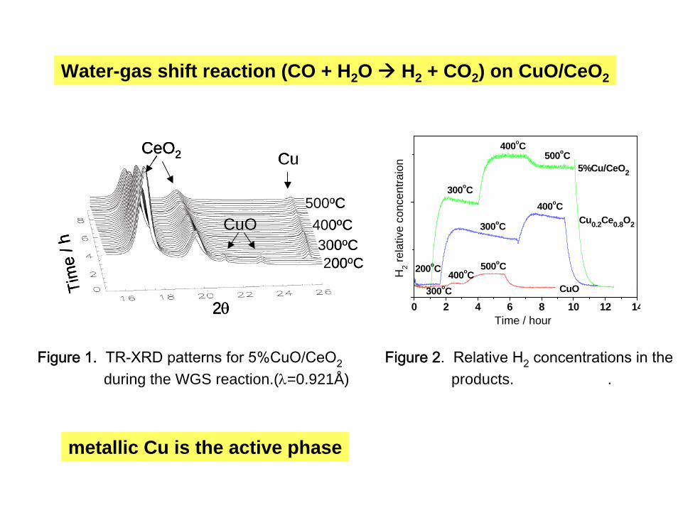
Water-gas shift reaction (CO + H2O H2 + CO2) on CuO/CeO2
Figure 1. TR-XRD patterns for 5%CuO/CeO2 Figure 2. Relative H2 concentrations in theduring the WGS reaction.(λ=0.921Å) products. .
metallic Cu is the active phase

Many materials constructed at the nanoscale lack the translational symmetry and long-range order of perfect crystals. This poses a realchallenge to the usual techniques for structure characterization. Acombination of techniques may be necessary to establish the structureand morphology of nano materials:
- X-ray diffraction- X-ray absorption fine structure- Electron microscopy, scanning tunneling microscopy- Raman and infrared spectroscopy- Pair distribution function measurements- etc
The diffraction patterns of nano materials may show only a few Bragg peaks, if any, and a pronounced diffuse component.
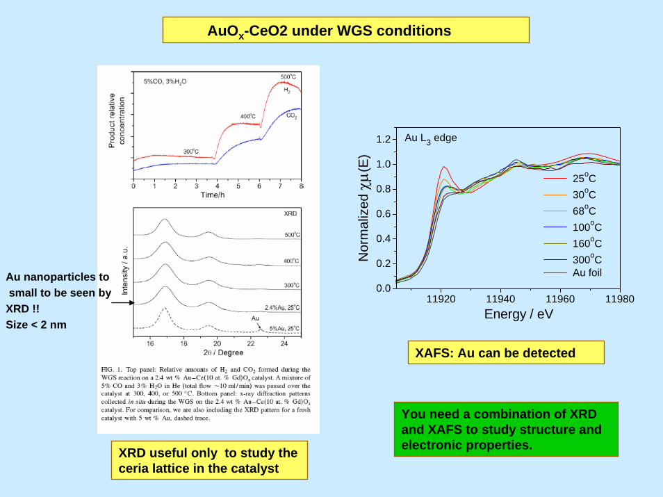
Au nanoparticles tosmall to be seen by
XRD !!Size < 2 nm
XRD useful only to study the ceria lattice in the catalyst
AuOx-CeO2 under WGS conditions
11920 11940 11960 119800.0
0.2
0.4
0.6
0.8
1.0
1.2
25oC 30oC 68oC 100oC 160oC 300oC Au foil
Nor
mal
ized
χμ(
E)
Energy / eV
Au L3 edge
XAFS: Au can be detected
You need a combination of XRD and XAFS to study structure and electronic properties.
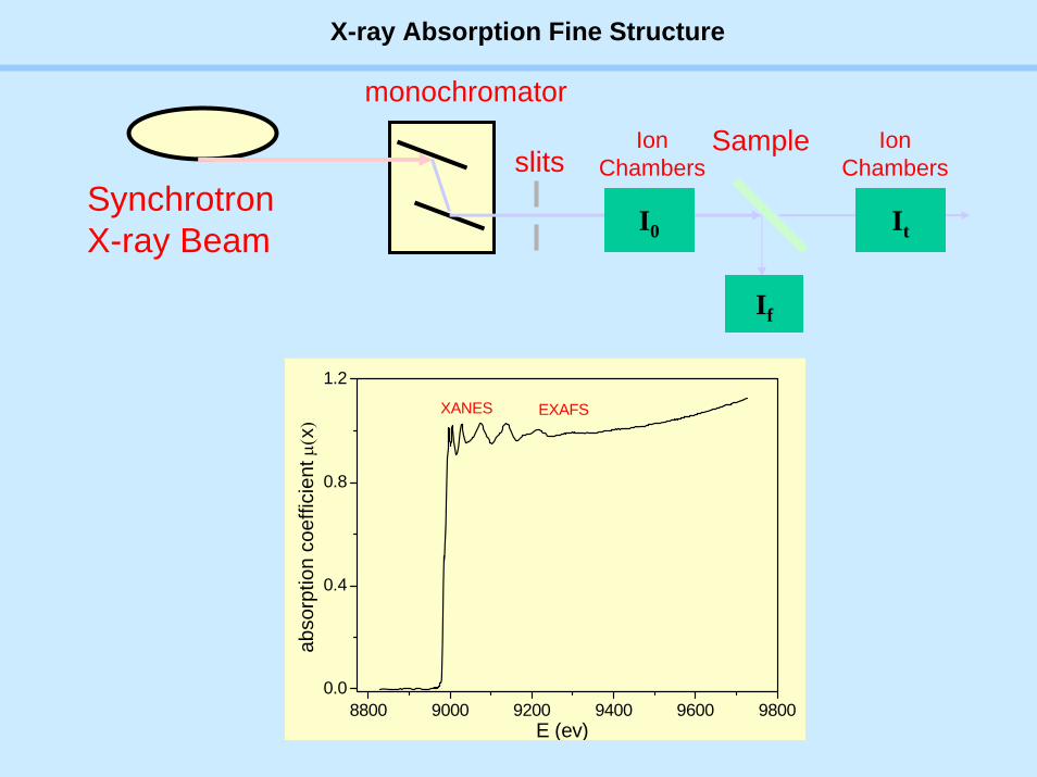
SynchrotronX-ray Beam
slits
monochromator
Sample IonChambers
I0 It
If
IonChambers
8800 9000 9200 9400 9600 98000.0
0.4
0.8
1.2
EXAFS
abso
rptio
n co
effic
ient
μ(x)
E (ev)
XANES
X-ray Absorption Fine Structure
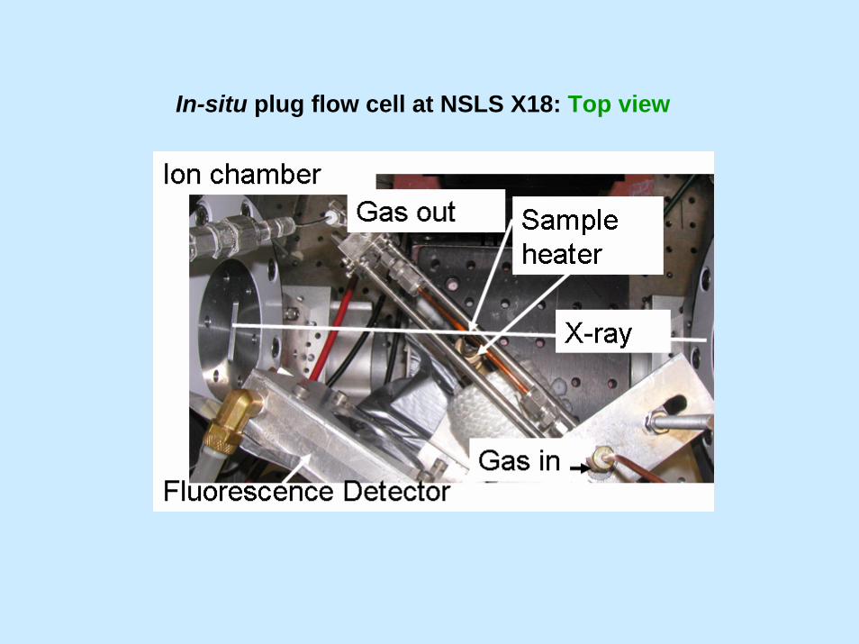
In-situ plug flow cell at NSLS X18: Top view

Quick EXAFS at NSLS X18B
•Typical times for
•Foils
•XANES 1 sec
•EXAFS 3 sec
•Dilute samples
•XANES 5 sec
•EXAFS 15 sec
•Adjustable Cam drives oscillation of monochromator
•Rapid readout of motor encoder and detectors (2000pts/sec)
Limitation beam intensity and sample concentration
Synchrotron Catalysis Consortium:
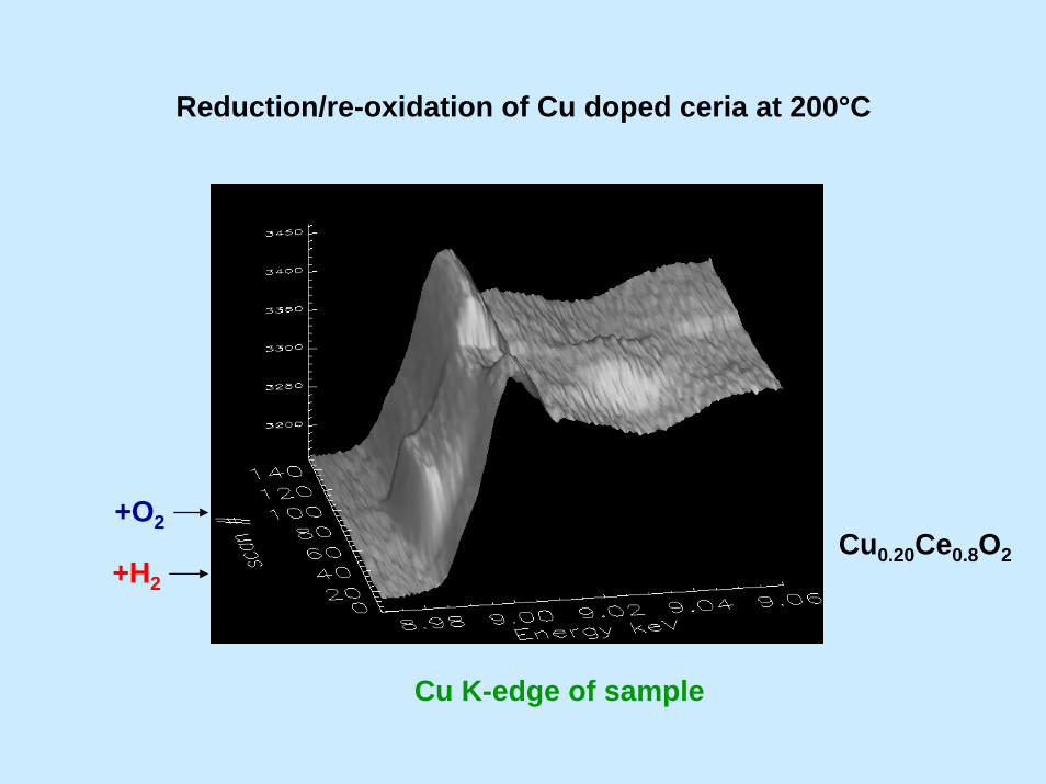
Reduction/re-oxidation of Cu doped ceria at 200°C
+H2
+O2Cu0.20Ce0.8O2
Cu K-edge of sample

PCA 3-component fit to reduction of doped ceria at 200°C
0 500 1000 1500 2000
-0.2
0.0
0.2
0.4
0.6
0.8
1.0
1.2
20% doped - reduction at 200oC
Mix
ing
Frac
tion
Time (sec)
starting phase intermediate phase ending phase

Projected XRD/XAFS beamline at NSLS-II

The instrumentation will take full advantage of the high intensityand brightness of the NSLS-II
It will have fast XRD (3ms time resolution) and fast XAFS ( < 1stime resolution). Ability to study metal loadings as diluted as< 0.1 % with quick XAFS.
Our proposed set-up will be the best combination of XRD/XAFSin the world. Superior in sensitivity and fast readout time to thoseexisting in HASYLAB/DESY (Hamburg) and SRS (Daresbury).