implementation of network on chip (noc) with mesh topology
TRANSCRIPT
Uma B.V. et.al. Implementation of Network on Chip (NoC) with Mesh Topology
Implementation of Network on Chip (NoC) with Mesh
Topology Uma B V
1*, Sagar Bamashetti
1, Krishna Daivajna
1
1Department of Electronics & Communication Engineering, RV College of Engineering®,
Bengaluru
Abstract
Network on Chip (NoC) is a new standard to make the interconnections
in a System on Chip (SoC) system. It overcomes the main drawback of
traditional bus based SoC, which have large delay, poor scalability and
small link bandwidth etc. NoC can replace traditional bus-based
architecture in SoC design methodology. Wiring complexity is reduced
in NoC, and it also increases speed and reliability. In this project NoC
with mesh topology (8 x 8) with 64 process nodes was implemented.
Implementation was done using Verilog HDL. Synthesis and Simulation
were carried out using Xilinx ISE 14.7. Flit is used as the basic flow unit
between process nodes. XY routing algorithm was employed. Virtual
channel flow control mechanism was used for flow control. Test bench
was implemented to verify the functional correctness of the NoC
implementation. Verilog HDL was used for the same. ISim simulator was
used for the simulation. NoC implementation functionality was verified.
Keywords: Network on Chip, Mesh topology, System on Chip, Verilog
HDL
1.0 Introduction
It NoC will replace bus-based architecture soon to become the
mainstream of SoC design methodology. NoC reduces complexity in
designing the wires and has better speed and reliability. NoC separates
communication supports modularity and Computation and IP reuse via
standard interfaces it also serves as a platform for system test, handles
data synchronization issue, and, hence improve engineering productivity
efficiency. In NoC technology the bus structure is replaced with a
network which is almost like the Internet. NoC consists of IP Cores,
network interfaces (NI), routers and physical links. IP cores of NoC are
computing units of the system, such as DSP unit, I/O units, memory and
CPU. Routers transmits the data from source node to its destinations.
Router that supports five parallel connections at once. It uses store and
forward for flow control. The packet switching mechanism is used. The
*Mail Address: Uma B V, Professor, Department of Electronics & Communication Engineering,
RV College of Engineering®, Bengaluru-59, Email:[email protected]
RVJSTEAM 2,1 (2021) 102
Uma B.V. et.al. Implementation of Network on Chip (NoC) with Mesh Topology
designed router supports a Mesh topology for communication and round
robin scheduling is used for data transmission [1]. Guideline to improve
virtual-channel router architecture for NoC. They evaluate network
performance of virtual-channel router by varying the number of virtual
channels and buffer depths, to find an efficient buffer scheme for the
virtual-channel router. As per their simulation results, there is
improvement in their network performance as the number of virtual
channels increases. Also, a greater number of virtual channels are not
effective for mesh based NoC, when we consider network performance
and buffer requirement. Larger buffer space has additional cost and
energy consumption [2]. Dally and Towles demonstrate the basic virtual-
channel router architecture in interconnection networks [3]. Virtual
Channel (VC) router that works in a pipelined fashion was proposed.
Each packet has four pipeline stages in the VC. In order to reduce router
delay, Look-Ahead Routing (LAR) and Speculative Arbitration (SPA)
mechanisms are proposed for basic VC router. Through this mechanism,
a single flit can travel through VC router within a single cycle. This low
latency VC router is introduced to NoC in [4]. They remove arbitration
logic and routing from the critical path using SPA and LAR mechanisms
and make a single cycle router architecture. Low latency router which
use adaptive routing. Two stage pipelined VC router is achieved by
means of LAR and SPA. For its simplified router architecture and
adaptive ability, this router has better performance both in energy
consumption and network delay [5]. Single cycle VC router for a 36-core
NoC with shared memory CMP system using 65nm technology. These
routers have low latency switch allocation mechanism and high
throughput, a low complexity virtual channel allocator and a dynamically
managed shared buffer to reduce the packet delay [6-7].
2.0 NOC Mesh topology
NoC Mesh Topology having five input port and five output port is
designed. Fig. 1a shows a typical Mesh topology architecture [2].
Network-on-Chip consists of Process nodes, routers, Network Interfaces
(NI), and physical links.
RVJSTEAM 2,1 (2021) 103

Uma B.V. et.al. Implementation of Network on Chip (NoC) with Mesh Topology
Fig. 1. a) Mesh based NoC architecture and b) Typical NoC router architecture [2]
Here each router has five input and five output ports corresponding to the
east, west, north and south directions also one for local processing
element (PE) [8-10]. Each of these ports will be connected to another
port on the neighbouring router through a set of channels (physical
interconnect wires). The function of the router is to route flits entering
from each input port to a corresponding output port and then toward its
final destinations. To realize this architecture, a router has input buffer
for each input port, a 5×5 crossbar switch to transmit traffic to the
appropriate output port and necessary control logic to ensure perfection
of routing results as shown in Fig. 1b.
2.1 Routing Algorithm
In 2D mesh, XY-routing is widely used for packet routing [11,12]. The
algorithm is deadlock-free for n-dimensional hypercubes and meshes, as
their Channel Dependency Graph (CDG) is acyclic. In order to remove
cycles, physical channels may be split into virtual channels. The path
taken by a packet using the XY routing algorithm for a Source (S) to a
destination (D) is shown in Fig. 2a on a (4×4) mesh. The allowed path is
shown in green while the disallowed paths are shown in red.
RVJSTEAM 2,1 (2021) 104
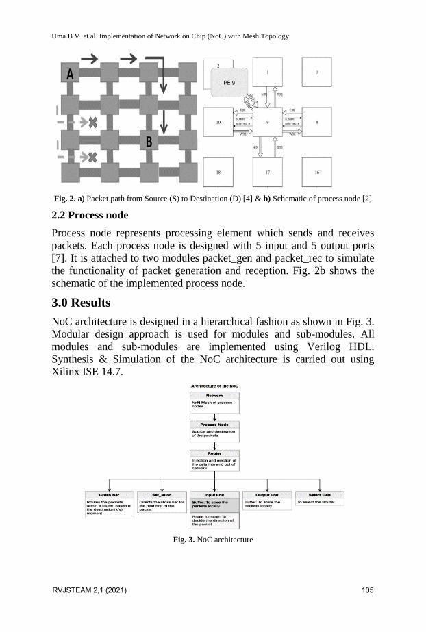
Uma B.V. et.al. Implementation of Network on Chip (NoC) with Mesh Topology
Fig. 2. a) Packet path from Source (S) to Destination (D) [4] & b) Schematic of process node [2]
2.2 Process node
Process node represents processing element which sends and receives
packets. Each process node is designed with 5 input and 5 output ports
[7]. It is attached to two modules packet_gen and packet_rec to simulate
the functionality of packet generation and reception. Fig. 2b shows the
schematic of the implemented process node.
3.0 Results
NoC architecture is designed in a hierarchical fashion as shown in Fig. 3.
Modular design approach is used for modules and sub-modules. All
modules and sub-modules are implemented using Verilog HDL.
Synthesis & Simulation of the NoC architecture is carried out using
Xilinx ISE 14.7.
Fig. 3. NoC architecture
RVJSTEAM 2,1 (2021) 105
Uma B.V. et.al. Implementation of Network on Chip (NoC) with Mesh Topology
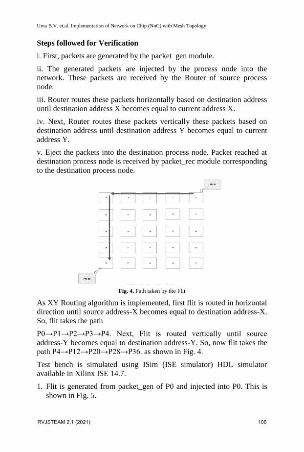
Steps followed for Verification
i. First, packets are generated by the packet_gen module.
ii. The generated packets are injected by the process node into the
network. These packets are received by the Router of source process
node.
iii. Router routes these packets horizontally based on destination address
until destination address X becomes equal to current address X.
iv. Next, Router routes these packets vertically these packets based on
destination address until destination address Y becomes equal to current
address Y.
v. Eject the packets into the destination process node. Packet reached at
destination process node is received by packet_rec module corresponding
to the destination process node.
Fig. 4. Path taken by the Flit
As XY Routing algorithm is implemented, first flit is routed in horizontal
direction until source address-X becomes equal to destination address-X.
So, flit takes the path
P0→P1→P2→P3→P4. Next, Flit is routed vertically until source
address-Y becomes equal to destination address-Y. So, now flit takes the
path P4→P12→P20→P28→P36. as shown in Fig. 4.
Test bench is simulated using ISim (ISE simulator) HDL simulator
available in Xilinx ISE 14.7.
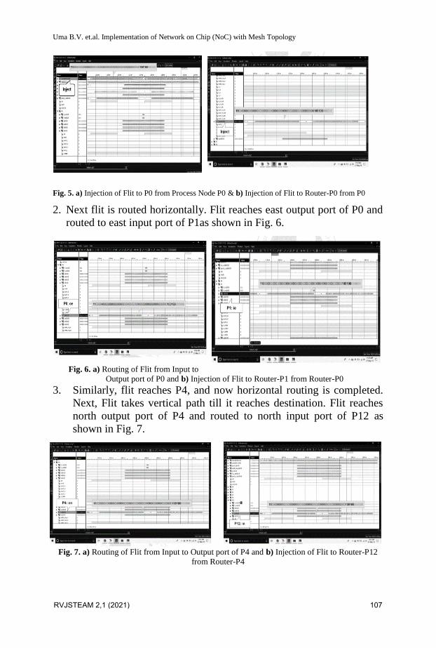
1. Flit is generated from packet_gen of P0 and injected into P0. This is
shown in Fig. 5.
RVJSTEAM 2,1 (2021) 106
Uma B.V. et.al. Implementation of Network on Chip (NoC) with Mesh Topology
Fig. 5. a) Injection of Flit to P0 from Process Node P0 & b) Injection of Flit to Router-P0 from P0
2. Next flit is routed horizontally. Flit reaches east output port of P0 and
routed to east input port of P1as shown in Fig. 6.
Fig. 6. a) Routing of Flit from Input to
Output port of P0 and b) Injection of Flit to Router-P1 from Router-P0
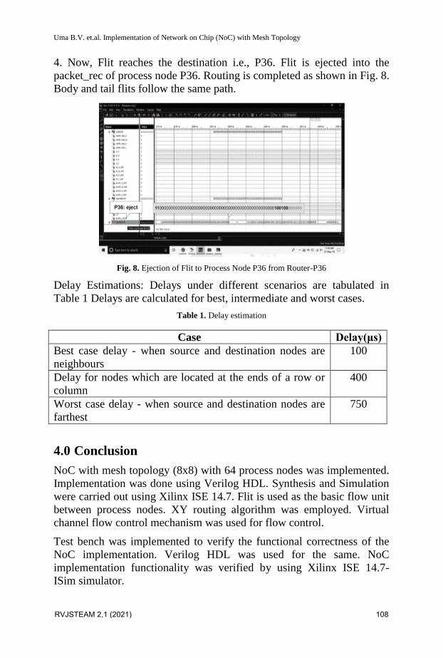
3. Similarly, flit reaches P4, and now horizontal routing is completed.
Next, Flit takes vertical path till it reaches destination. Flit reaches
north output port of P4 and routed to north input port of P12 as
shown in Fig. 7.
Fig. 7. a) Routing of Flit from Input to Output port of P4 and b) Injection of Flit to Router-P12
from Router-P4
RVJSTEAM 2,1 (2021) 107
Uma B.V. et.al. Implementation of Network on Chip (NoC) with Mesh Topology
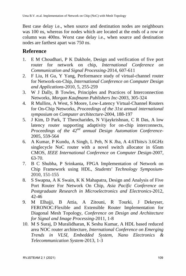
4. Now, Flit reaches the destination i.e., P36. Flit is ejected into the
packet_rec of process node P36. Routing is completed as shown in Fig. 8.
Body and tail flits follow the same path.
Fig. 8. Ejection of Flit to Process Node P36 from Router-P36
Delay Estimations: Delays under different scenarios are tabulated in
Table 1 Delays are calculated for best, intermediate and worst cases.
Table 1. Delay estimation
Case Delay(μs)
Best case delay - when source and destination nodes are
neighbours
100
Delay for nodes which are located at the ends of a row or
column
400
Worst case delay - when source and destination nodes are
farthest
750
4.0 Conclusion
NoC with mesh topology (8x8) with 64 process nodes was implemented.
Implementation was done using Verilog HDL. Synthesis and Simulation
were carried out using Xilinx ISE 14.7. Flit is used as the basic flow unit
between process nodes. XY routing algorithm was employed. Virtual
channel flow control mechanism was used for flow control.
Test bench was implemented to verify the functional correctness of the
NoC implementation. Verilog HDL was used for the same. NoC
implementation functionality was verified by using Xilinx ISE 14.7-
ISim simulator.
RVJSTEAM 2,1 (2021) 108
Uma B.V. et.al. Implementation of Network on Chip (NoC) with Mesh Topology
Best case delay i.e., when source and destination nodes are neighbours
was 100 ns, whereas for nodes which are located at the ends of a row or
column was 400ns. Worst case delay i.e., when source and destination
nodes are farthest apart was 750 ns.
Reference
1. E M Choudhari, P K Dakhole, Design and verification of five port
router for network on chip, International Conference on
Communication and Signal Processing-2014, 607-611
2. F Liu, H Gu, Y Yang, Performance study of virtual-channel router
for Network-on-Chip, International Conference on Computer Design
and Applications-2010, 5, 255-259
3. W J Dally, B Towles, Principles and Practices of Interconnection
Networks, Morgan Kaufmann Publishers Inc-2003, 305-324
4. R Mullins, A West, S Moore, Low-Latency Virtual-Channel Routers
for On-Chip Networks, Proceedings of the 31st annual international
symposium on Computer architecture-2004, 188-197
5. J Kim, D Park, T Theocharides, N Vijaykrishnan, C R Das, A low
latency router supporting adaptivity for on-chip interconnects,
Proceedings of the 42nd
annual Design Automation Conference-
2005, 559-564
6. A Kumar, P Kundu, A Singh, L Peh, N K Jha, A 4.6Tbits/s 3.6GHz
singlecycle NoC router with a novel switch allocator in 65nm
CMOS, IEEE International Conference on Computer Design-2007,
63-70.
7. B C Shubha, P Srinkanta, FPGA Implementation of Network on
Chip Framework using HDL, Students' Technology Symposium-
2010, 151-155
8. S Swapna, A K Swain, K K Mahapatra, Design and Analysis of Five
Port Router For Network On Chip, Asia Pacific Conference on
Postgraduate Research in Microelectronics and Electronics-2012,
42-46
9. M Elhajji, B Attia, A Zitouni, R Tourki, J Dekeyser,
FERONOC:Flexible and Extensible Router Implementation for
Diagonal Mesh Topology, Conference on Design and Architecture
for Signal and Image Processing-2011, 1-8
10. M S Suraj, D Muralidharan, K Seshu Kumar, A HDL based reduced
area NOC router architecture, International Conference on Emerging
Trends in VLSI, Embedded System, Nano Electronics &
Telecommunication System-2013, 1-3
RVJSTEAM 2,1 (2021) 109
Uma B.V. et.al. Implementation of Network on Chip (NoC) with Mesh Topology
11. H Elmiligi, A A Morgan, M W El-Kharashi, F Gebali, Performance
Analysis of Networks-on-Chip Routers, 2nd
International Design and
Test Workshop, Cairo, Egypt-2007, 232-236
12. P Gehlot, S S Chouhan, Performance Evaluation of Network on Chip
Architectures, International Conference on Emerging Trends in
Electronics and Photonic Devices & Systems-2009, 124-127
RVJSTEAM 2,1 (2021) 110