implementation of scr denox technology - china power 2006 · in implementation of scr denox...
TRANSCRIPT
Implementation of SCR DeNOx Technology
on Coal-Fired Boilers in P.R. China Hans Jensen-Holm
Haldor Topsøe A/S, Denmark
Nan-Yu Topsøe Haldor Topsøe A/S, Denmark
Jim Jianhua Cui
Haldor Topsøe International, P.R. China
Summary To construct high-dust SCR DeNOx plants for Chinese coal-fired power stations, some special concerns have to be taken to achieve a sound system design. The generally high ash content of Chinese coals makes proper design of the SCR reactor and selection of the catalyst type very important. High ash concentrations imply a severe risk of catalyst plugging and erosion. This can be avoided through careful catalyst selection and design of critical parts as the reactor, gas flow rectifier and duct internals to ensure uniform distribution of the flue gas flow and ash particulates. The design must be reliably founded in thorough and correct model work, applying CFD (Computational Fluid Dynamics) as well as physical scale model tests.
In selection of the proper catalyst model, the impact of the various design performance parameters must be assessed. Especially for Chinese coals, the selection of catalyst must account for potential fouling of the catalyst active sites and ensuing deactivation caused by a high calcium oxide content of the fly ash.
The paper details key system design requirements for operating success in challenging applications, illustrated by presentation of some design issues addressed in implementation of SCR DeNOx technology on a 600 MW boiler at Taishan Thermal Power Plant (Guangdong Province) and on a 600 MW boiler at Yangcheng Thermal Power Plant (Shanxi Province).
HALDOR TOPSOE 1
Introduction Over the years the requirements for the NOx removal efficiency on coal-fired boilers have increased from around 80% to now in many cases 90% or even higher. To achieve the objective of a reliable DeNOx unit that at all times provides the desired NOx removal efficiency with a minimum of ammonia slip, it is essential that vital parts of the system are designed with due consideration to the specific conditions under which the unit will be operated. This requires a close integration of know-how within catalyst technology, process technology and engineering.
The catalyst must be designed to take into account the flue gas characteristics and the available window of operating parameters, but a prerequisite for the catalyst to perform at its best is proper design of critical equipment as SCR reactor and duct internals and the ammonia injection system. This is crucial to provide uniform flow conditions at the catalyst layers and homogeneous mixing of the ammonia agent into the flue gas. Flow modelling of the SCR DeNOx unit by Computational Fluid Dynamics (CFD) and physical scale models is an indispensable tool for achieving this goal.
The SCR Catalyst The heart of the SCR DeNOx process is the catalyst on which injected ammonia reacts with NOx in the flue gas to form nitrogen and water vapour. The commonly applied catalysts are all based on a porous titanium-dioxide carrier material on which the catalytically active components, vanadium pentoxide and tungsten trioxide, are dispersed. To provide a large gas contact area with a minimum pressure loss, the catalysts are provided as elements containing a large number of parallel channels (corrugated or extruded honeycomb catalysts) or a number of parallel, spaced plates (plate-type catalysts). Each type of catalyst is offered in a number of different models with varying channel size (often referred to as pitch), wall thickness and varying chemical composition adjusted to specific operating conditions. The choice of pitch and wall thickness is influenced by the ash loading of the flue gas. Larger-channel catalysts with minimum 0.8 mm wall thickness are selected for operation in units on coal-fired boilers.
Several factors enter into the design of the catalyst loading for an SCR DeNOx system:
- Required NOx removal efficiency
- Maximum tolerable amount of unreacted ammonia in the exhaust gas (ammonia slip)
- Maximum allowable oxidation rate of SO2 to SO3 to avoid fouling of downstream equipment with ammonium sulphates
- Desired lifetime of the catalyst loading and prospected catalyst deactivation rate based on the amount of ash in the flue gas and its constituents
HALDOR TOPSOE 2
In high-dust SCR units on coal-fired boilers a gradual degradation of the catalyst with loss of activity occurs, primarily due to the exposure to fly ash. A number of factors contribute to deterioration of the catalyst performance, determining its useful life, and the design of the catalyst loading must take into account the impact of the operating environment in terms of poisoning characteristics, ash concentration, and erosion potential:
- Chemical or physical impact of fly ash components on catalyst’s active sites, usually referred to as poisoning.
- Fouling of the catalyst surface by very fine ash particles, physically blocking the access to the active sites or reducing the active surface area
- Inhibition by condensation of ammonia bisulphate in the catalyst pore system, reducing the active surface area
- Thermal degradation of the pore system (sintering) reducing the active surface area
- Plugging of catalyst channels reducing the effective volume of the installed catalyst
- Erosion by abrasive components in the fly ash in case of inappropriate gas flow conditions in the SCR reactor
Obviously, thorough knowledge of how these factors affect catalyst performance is essential in selection of the optimum catalyst type.
Poisoning Chemical poisoning is chemisorption of components on the active sites of the catalyst resulting in loss of activity. Aerosols of alkali metals as sodium and potassium are of prime concern. The aerosols adhere to the surface of the catalyst and are readily transported to the active sites by surface diffusion. The poisoning mechanism is believed to occur via a chemical binding to the so-called Brønsted-acid sites which also adsorb and “activate” the ammonia (see Figure 1), thereby blocking the catalytic cycle.
HALDOR TOPSOE 3
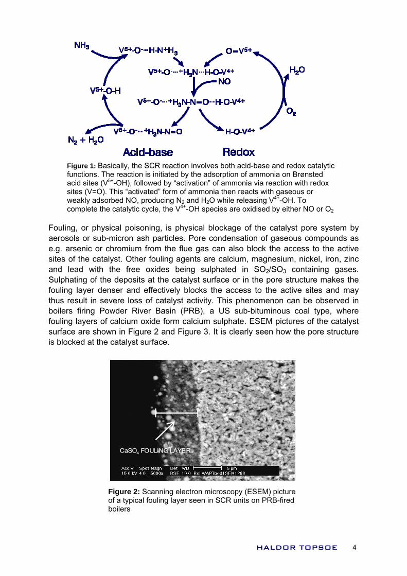
Figure 1: Basically, the SCR reaction involves both acid-base and redox catalytic functions. The reaction is initiated by the adsorption of ammonia on Brønsted acid sites (V5+-OH), followed by “activation” of ammonia via reaction with redox sites (V=O). This “activated” form of ammonia then reacts with gaseous or weakly adsorbed NO, producing N2 and H2O while releasing V4+-OH. To complete the catalytic cycle, the V4+-OH species are oxidised by either NO or O2
Fouling, or physical poisoning, is physical blockage of the catalyst pore system by aerosols or sub-micron ash particles. Pore condensation of gaseous compounds as e.g. arsenic or chromium from the flue gas can also block the access to the active sites of the catalyst. Other fouling agents are calcium, magnesium, nickel, iron, zinc and lead with the free oxides being sulphated in SO2/SO3 containing gases. Sulphating of the deposits at the catalyst surface or in the pore structure makes the fouling layer denser and effectively blocks the access to the active sites and may thus result in severe loss of catalyst activity. This phenomenon can be observed in boilers firing Powder River Basin (PRB), a US sub-bituminous coal type, where fouling layers of calcium oxide form calcium sulphate. ESEM pictures of the catalyst surface are shown in Figure 2 and Figure 3. It is clearly seen how the pore structure is blocked at the catalyst surface.
CaSO4 FOULING LAYER
Figure 2: Scanning electron microscopy (ESEM) picture of a typical fouling layer seen in SCR units on PRB-fired boilers
HALDOR TOPSOE 4
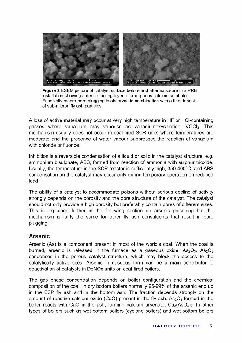
Figure 3 ESEM picture of catalyst surface before and after exposure in a PRB installation showing a dense fouling layer of amorphous calcium sulphate. Especially macro-pore plugging is observed in combination with a fine deposit of sub-micron fly ash particles
A loss of active material may occur at very high temperature in HF or HCl-containing gasses where vanadium may vaporise as vanadiumoxychloride, VOCl3. This mechanism usually does not occur in coal-fired SCR units where temperatures are moderate and the presence of water vapour suppresses the reaction of vanadium with chloride or fluoride.
Inhibition is a reversible condensation of a liquid or solid in the catalyst structure, e.g. ammonium bisulphate, ABS, formed from reaction of ammonia with sulphur trioxide. Usually, the temperature in the SCR reactor is sufficiently high, 350-400°C, and ABS condensation on the catalyst may occur only during temporary operation on reduced load.
The ability of a catalyst to accommodate poisons without serious decline of activity strongly depends on the porosity and the pore structure of the catalyst. The catalyst should not only provide a high porosity but preferably contain pores of different sizes. This is explained further in the following section on arsenic poisoning but the mechanism is fairly the same for other fly ash constituents that result in pore plugging. Arsenic Arsenic (As) is a component present in most of the world’s coal. When the coal is burned, arsenic is released in the furnace as a gaseous oxide, As2O3. As2O3 condenses in the porous catalyst structure, which may block the access to the catalytically active sites. Arsenic in gaseous form can be a main contributor to deactivation of catalysts in DeNOx units on coal-fired boilers.
The gas phase concentration depends on boiler configuration and the chemical composition of the coal. In dry bottom boilers normally 95-99% of the arsenic end up in the ESP fly ash and in the bottom ash. The fraction depends strongly on the amount of reactive calcium oxide (CaO) present in the fly ash. As2O3 formed in the boiler reacts with CaO in the ash, forming calcium arsenate, Ca3(AsO4)2. In other types of boilers such as wet bottom boilers (cyclone boilers) and wet bottom boilers
HALDOR TOPSOE 5
with ash recirculation, the fraction of arsenic present in gas phase can be significantly higher.
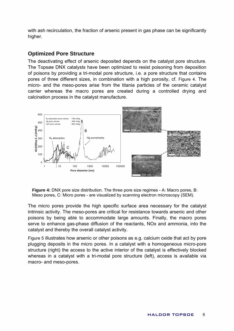
Optimized Pore Structure The deactivating effect of arsenic deposited depends on the catalyst pore structure. The Topsøe DNX catalysts have been optimized to resist poisoning from deposition of poisons by providing a tri-modal pore structure, i.e. a pore structure that contains pores of three different sizes, in combination with a high porosity, cf. Figure 4. The micro- and the meso-pores arise from the titania particles of the ceramic catalyst carrier whereas the macro pores are created during a controlled drying and calcination process in the catalyst manufacture.
0
100
200
300
400
500
600
1 10 100 1000 10000 100000Pore diameter [nm]
d(v)
/d(lo
g d
p) [m
l/kg]
N2 adsorption Hg porosimetry
C
B
A
N2 adsorption pore volume : 196 ml/kg Hg pore volume : 366 ml/kgH2O pore volume : 600 ml/kg
200 nm
A: Macro pores
200 µm
5 µm
B: Meso pores
C: Micro pores
200 nm
A: Macro pores
200 µm
A: Macro pores
200 µm
5 µm
B: Meso pores
C: Micro pores
Figure 4: DNX pore size distribution. The three pore size regimes - A: Macro pores, B: Meso pores, C: Micro pores - are visualized by scanning electron microscopy (SEM).
The micro pores provide the high specific surface area necessary for the catalyst intrinsic activity. The meso-pores are critical for resistance towards arsenic and other poisons by being able to accommodate large amounts. Finally, the macro pores serve to enhance gas-phase diffusion of the reactants, NOx and ammonia, into the catalyst and thereby the overall catalyst activity.
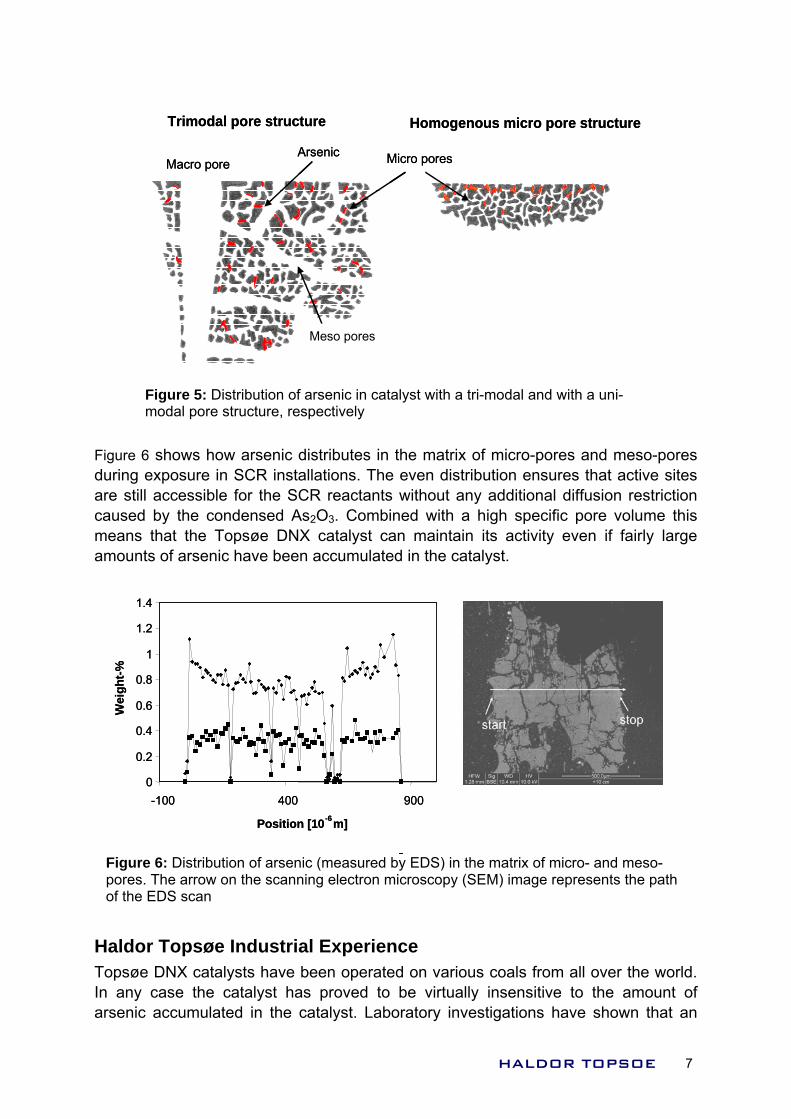
Figure 5 illustrates how arsenic or other poisons as e.g. calcium oxide that act by pore plugging deposits in the micro pores. In a catalyst with a homogeneous micro-pore structure (right) the access to the active interior of the catalyst is effectively blocked whereas in a catalyst with a tri-modal pore structure (left), access is available via macro- and meso-pores.
HALDOR TOPSOE 6
Macro pore
Meso pores
Arsenic Micro pores
Trimodal pore structure Homogenous micro pore structure
Macro pore
Meso pores
Arsenic Micro pores
Trimodal pore structure Homogenous micro pore structure
Figure 5: Distribution of arsenic in catalyst with a tri-modal and with a uni-modal pore structure, respectively
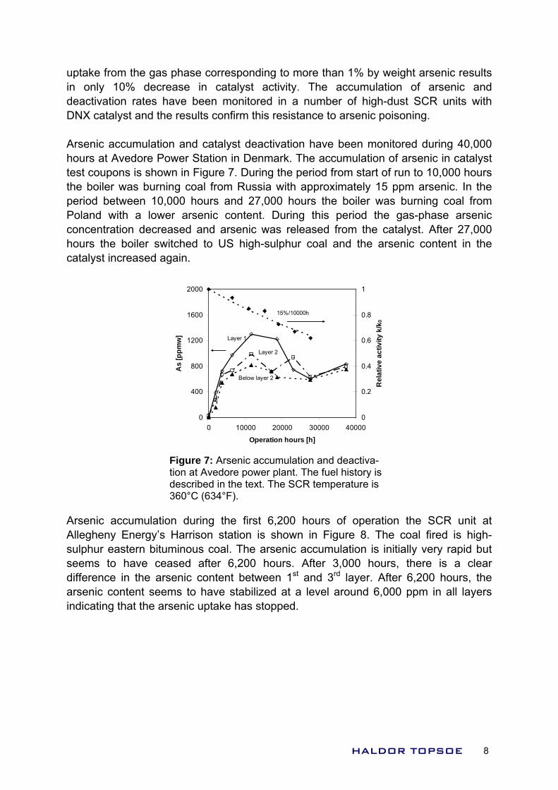
Figure 6 shows how arsenic distributes in the matrix of micro-pores and meso-pores during exposure in SCR installations. The even distribution ensures that active sites are still accessible for the SCR reactants without any additional diffusion restriction caused by the condensed As2O3. Combined with a high specific pore volume this means that the Topsøe DNX catalyst can maintain its activity even if fairly large amounts of arsenic have been accumulated in the catalyst.
0
0.2
0.4
0.6
0.8
1
1.2
1.4
-100 400 900
Position [10-6m]
Wei
ght-%
0
0.2
0.4
0.6
0.8
1
1.2
1.4
-100 400 900
Position [10-6m]
Wei
ght-%
Figure 6: Distribution of arsenic (measured by EDS) in the matrix of micro- and meso-pores. The arrow on the scanning electron microscopy (SEM) image represents the path of the EDS scan
Haldor Topsøe Industrial Experience Topsøe DNX catalysts have been operated on various coals from all over the world. In any case the catalyst has proved to be virtually insensitive to the amount of arsenic accumulated in the catalyst. Laboratory investigations have shown that an
HALDOR TOPSOE 7
uptake from the gas phase corresponding to more than 1% by weight arsenic results in only 10% decrease in catalyst activity. The accumulation of arsenic and deactivation rates have been monitored in a number of high-dust SCR units with DNX catalyst and the results confirm this resistance to arsenic poisoning. Arsenic accumulation and catalyst deactivation have been monitored during 40,000 hours at Avedore Power Station in Denmark. The accumulation of arsenic in catalyst test coupons is shown in Figure 7. During the period from start of run to 10,000 hours the boiler was burning coal from Russia with approximately 15 ppm arsenic. In the period between 10,000 hours and 27,000 hours the boiler was burning coal from Poland with a lower arsenic content. During this period the gas-phase arsenic concentration decreased and arsenic was released from the catalyst. After 27,000 hours the boiler switched to US high-sulphur coal and the arsenic content in the catalyst increased again.
0
400
800
1200
1600
2000
0 10000 20000 30000 40000
Operation hours [h]
As
[ppm
w]
0
0.2
0.4
0.6
0.8
1
Rel
ativ
e ac
tivity
k/k
0
Layer 1
Layer 2
Below layer 2
15%/10000h
Figure 7: Arsenic accumulation and deactiva-tion at Avedore power plant. The fuel history is described in the text. The SCR temperature is 360°C (634°F).
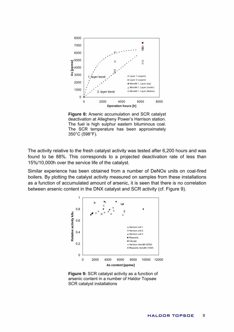
Arsenic accumulation during the first 6,200 hours of operation the SCR unit at Allegheny Energy’s Harrison station is shown in Figure 8. The coal fired is high-sulphur eastern bituminous coal. The arsenic accumulation is initially very rapid but seems to have ceased after 6,200 hours. After 3,000 hours, there is a clear difference in the arsenic content between 1st and 3rd layer. After 6,200 hours, the arsenic content seems to have stabilized at a level around 6,000 ppm in all layers indicating that the arsenic uptake has stopped.
HALDOR TOPSOE 8
0
1000
2000
3000
4000
5000
6000
7000
8000
0 2000 4000 6000 8000Operation hours [h]
As
[ppm
w]
Layer 1 coupons
Layer 3 coupons
Monolith 1. Layer (top)
Monolith 1. Layer (center)
Monolith 1. Layer (Bottom)
1. layer trend
3. layer trend
Figure 8: Arsenic accumulation and SCR catalystdeactivation at Allegheny Power’s Harrison station.The fuel is high sulphur eastern bituminous coal.The SCR temperature has been approximately350°C (598°F).
The activity relative to the fresh catalyst activity was tested after 6,200 hours and was found to be 88%. This corresponds to a projected deactivation rate of less than 15%/10,000h over the service life of the catalyst.
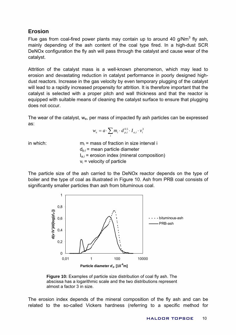
Similar experience has been obtained from a number of DeNOx units on coal-fired boilers. By plotting the catalyst activity measured on samples from these installations as a function of accumulated amount of arsenic, it is seen that there is no correlation between arsenic content in the DNX catalyst and SCR activity (cf. Figure 9).
0
0.2
0.4
0.6
0.8
1
0 2000 4000 6000 8000 10000 12000
As content [ppmw]
Rel
ativ
e ac
tivity
k/k
0
Harrison unit 1Harrison unit 2Harrison unit 3PleasantsCayugaHarrison monolith 6200hPleasants monolith 3100h
Figure 9: SCR catalyst activity as a function of arsenic content in a number of Haldor Topsøe SCR catalyst installations
HALDOR TOPSOE 9
Erosion Flue gas from coal-fired power plants may contain up to around 40 g/Nm3 fly ash, mainly depending of the ash content of the coal type fired. In a high-dust SCR DeNOx configuration the fly ash will pass through the catalyst and cause wear of the catalyst. Attrition of the catalyst mass is a well-known phenomenon, which may lead to erosion and devastating reduction in catalyst performance in poorly designed high-dust reactors. Increase in the gas velocity by even temporary plugging of the catalyst will lead to a rapidly increased propensity for attrition. It is therefore important that the catalyst is selected with a proper pitch and wall thickness and that the reactor is equipped with suitable means of cleaning the catalyst surface to ensure that plugging does not occur. The wear of the catalyst, we, per mass of impacted fly ash particles can be expressed as:
3,
5.0, iia
iipie vIdmaw ⋅⋅⋅⋅= ∑
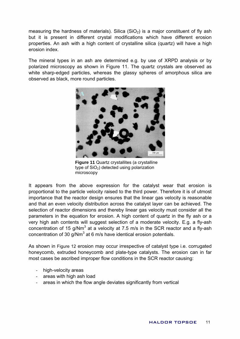
in which: mi = mass of fraction in size interval i dp,i = mean particle diameter Ia,i = erosion index (mineral composition) vi = velocity of particle The particle size of the ash carried to the DeNOx reactor depends on the type of boiler and the type of coal as illustrated in Figure 10. Ash from PRB coal consists of significantly smaller particles than ash from bituminous coal.
0
0,2
0,4
0,6
0,8
1
0,01 1 100 10000
Particle diameter d p [10-6m]
d(v
/V)/d
(log(
dp
))
bituminous-ashPRB-ash
Figure 10: Examples of particle size distribution of coal fly ash. The abscissa has a logarithmic scale and the two distributions represent almost a factor 3 in size.
The erosion index depends of the mineral composition of the fly ash and can be related to the so-called Vickers hardness (referring to a specific method for
HALDOR TOPSOE 10
measuring the hardness of materials). Silica (SiO2) is a major constituent of fly ash but it is present in different crystal modifications which have different erosion properties. An ash with a high content of crystalline silica (quartz) will have a high erosion index.
The mineral types in an ash are determined e.g. by use of XRPD analysis or by polarized microscopy as shown in Figure 11. The quartz crystals are observed as white sharp-edged particles, whereas the glassy spheres of amorphous silica are observed as black, more round particles.
A
Figure 11 Quartz crystallites (a crystalline type of SiO2) detected using polarization microscopy
It appears from the above expression for the catalyst wear that erosion is proportional to the particle velocity raised to the third power. Therefore it is of utmost importance that the reactor design ensures that the linear gas velocity is reasonable and that an even velocity distribution across the catalyst layer can be achieved. The selection of reactor dimensions and thereby linear gas velocity must consider all the parameters in the equation for erosion. A high content of quartz in the fly ash or a very high ash contents will suggest selection of a moderate velocity. E.g. a fly-ash concentration of 15 g/Nm3 at a velocity at 7.5 m/s in the SCR reactor and a fly-ash concentration of 30 g/Nm3 at 6 m/s have identical erosion potentials.
As shown in Figure 12 erosion may occur irrespective of catalyst type i.e. corrugated honeycomb, extruded honeycomb and plate-type catalysts. The erosion can in far most cases be ascribed improper flow conditions in the SCR reactor causing:
- high-velocity areas - areas with high ash load - areas in which the flow angle deviates significantly from vertical
HALDOR TOPSOE 11
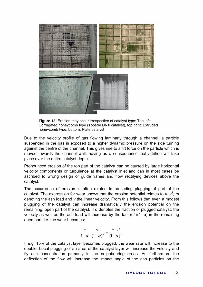
Figure 12: Erosion may occur irrespective of catalyst type: Top left: Corrugated honeycomb type (Topsøe DNX catalyst), top right: Extruded honeycomb type, bottom: Plate catalyst
Due to the velocity profile of gas flowing laminarly through a channel, a particle suspended in the gas is exposed to a higher dynamic pressure on the side turning against the centre of the channel. This gives rise to a lift force on the particle which is moved towards the channel wall, having as a consequence that attrition will take place over the entire catalyst depth.
Pronounced erosion of the top part of the catalyst can be caused by large horizontal velocity components or turbulence at the catalyst inlet and can in most cases be ascribed to wrong design of guide vanes and flow rectifying devices above the catalyst.
The occurrence of erosion is often related to preceding plugging of part of the catalyst. The expression for wear shows that the erosion potential relates to m·v3, m denoting the ash load and v the linear velocity. From this follows that even a modest plugging of the catalyst can increase dramatically the erosion potential on the remaining, open part of the catalyst. If α denotes the fraction of plugged catalyst, the velocity as well as the ash load will increase by the factor 1/(1- α) in the remaining open part, i.e. the wear becomes:
4
3
3
3
)1()1(1 ααα −⋅
=−
⋅−
vmvm
If e.g. 15% of the catalyst layer becomes plugged, the wear rate will increase to the double. Local plugging of an area of the catalyst layer will increase the velocity and fly ash concentration primarily in the neighbouring areas. As furthermore the deflection of the flow will increase the impact angle of the ash particles on the
HALDOR TOPSOE 12
catalyst surface, the result is that even a modest plugging of the catalyst can locally cause a large increase in erosion propensity.
Obviously, it is therefore very important to prevent that plugging of the catalyst occurs. In the design phase care should be taken ensuring a uniform flow distribution over the entire reactor area, ensuring a vertical flow angle, applying proper means of catalyst cleaning, as well as selecting a proper pitch of the catalyst.
The possibility of carry-over of LPA (large particle ash) or popcorns from the boiler should be considered in the design phase of the SCR project. This includes design of ash hoppers and gas channels or even insertion of a popcorn screen to allow separation of these particles upstream the SCR reactor. As a safeguard, the catalyst modules should include a top grating with a wire mesh with a pitch smaller than the catalyst pitch. Possible deposits of LPA on the top gratings must be removed at intervals in order not to cause unbalanced flow and impediment in the efficiency of soot blowers.
Flow modelling Proper design of the SCR reactor, gas channels and the ammonia injection and mixing system is a mandatory precondition for achieving optimum performance of the catalyst. In a high-dust DeNOx unit special care must be taken to ensure correct gas flow conditions to the catalyst layers in order to avert damage to the catalyst in the form of plugging or erosion as described above. Use of gas flow modelling by Computational Fluid Dynamics (CFD) or in physical scale models has proven an efficient and often indispensable tool to accomplish these goals. The general objectives of the model work are to:
- Ensure a high degree of velocity uniformity upstream the ammonia injection - To verify proper mixing of ammonia into the flue gas - Optimise the layout of ducts and reactor within given constraints - Develop and optimise necessary flow control devices - Ensure a high degree of velocity uniformity at the entrance to the first catalyst
layer - Ensure a gas flow angel deviating the minimum from vertical - Make sure that formation of dust deposits is not being promoted - Minimise system pressure drop
Although the availability of still more powerful computers makes CFD modelling less time consuming, the theoretical basis for modelling of ash behaviour as e.g. precipitation and re-entrainment is still weak. Furthermore, optimisation of guide vanes often requires several iterations. Thus, modelling of high-dust DeNOx units, where prevention of dust fall-out and erosion are main objectives, is often most efficiently done with physical scale models.
The use of physical model tests in various aspects of the design work is illustrated in the following by discussion of selected issues from two Chinese projects. Finally, an example is given on the use of CFD modelling in combination with physical model tests for trouble shooting of a DeNOx unit experiencing problems with dust build-up on the catalyst.
HALDOR TOPSOE 13
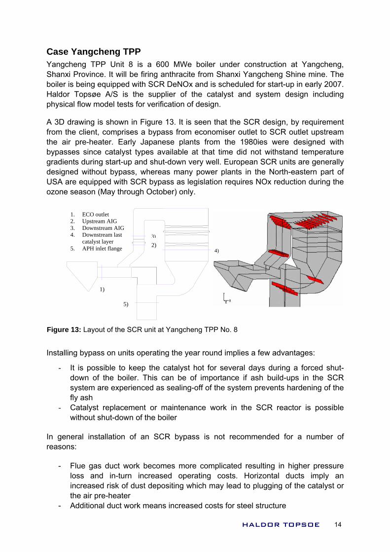
Case Yangcheng TPP Yangcheng TPP Unit 8 is a 600 MWe boiler under construction at Yangcheng, Shanxi Province. It will be firing anthracite from Shanxi Yangcheng Shine mine. The boiler is being equipped with SCR DeNOx and is scheduled for start-up in early 2007. Haldor Topsøe A/S is the supplier of the catalyst and system design including physical flow model tests for verification of design.
A 3D drawing is shown in Figure 13. It is seen that the SCR design, by requirement from the client, comprises a bypass from economiser outlet to SCR outlet upstream the air pre-heater. Early Japanese plants from the 1980ies were designed with bypasses since catalyst types available at that time did not withstand temperature gradients during start-up and shut-down very well. European SCR units are generally designed without bypass, whereas many power plants in the North-eastern part of USA are equipped with SCR bypass as legislation requires NOx reduction during the ozone season (May through October) only.
Installing bypass on units operating the year round implies a few advantages:
- It is possible to keep the catalyst hot for several days during a forced shut-down of the boiler. This can be of importance if ash build-ups in the SCR system are experienced as sealing-off of the system prevents hardening of the fly ash
- Catalyst replacement or maintenance work in the SCR reactor is possible without shut-down of the boiler
In general installation of an SCR bypass is not recommended for a number of reasons:
- Flue gas duct work becomes more complicated resulting in higher pressure loss and in-turn increased operating costs. Horizontal ducts imply an increased risk of dust depositing which may lead to plugging of the catalyst or the air pre-heater
- Additional duct work means increased costs for steel structure
1. ECO outlet 2. Upstream AIG 3. Downstream AIG 4. Downstream last
catalyst layer 5. APH inlet flange
3)
4)
5)
2)
1)
Figure 13: Layout of the SCR unit at Yangcheng TPP No. 8
HALDOR TOPSOE 14
- Reliable and tight dampers are required to avoid unintended bypass of the
- pers is difficult to avoid. This may affect the
- rs have become
creased Pressure Drop
pressure total pressure drop from economiser outlet
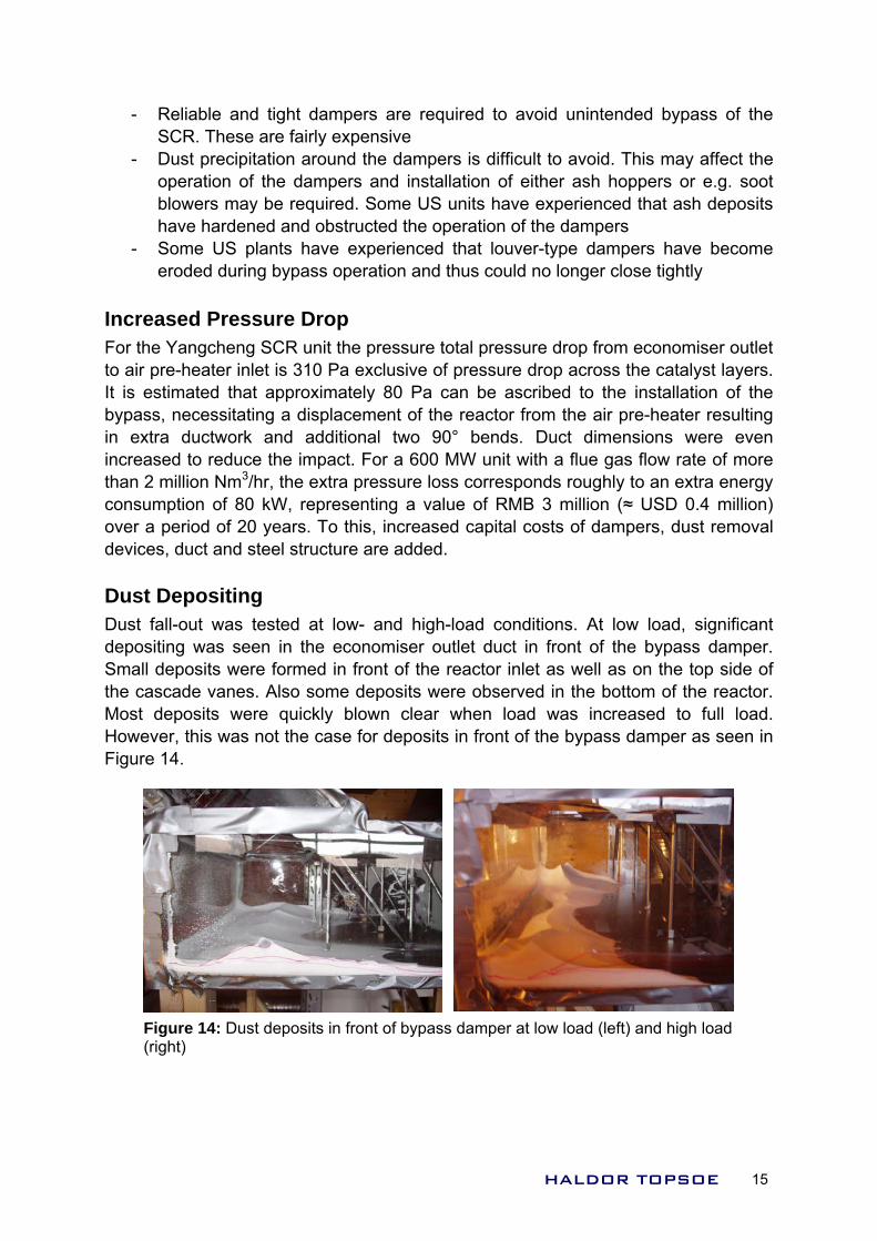
ust Depositing ted at low- and high-load conditions. At low load, significant
SCR. These are fairly expensive Dust precipitation around the damoperation of the dampers and installation of either ash hoppers or e.g. soot blowers may be required. Some US units have experienced that ash deposits have hardened and obstructed the operation of the dampers Some US plants have experienced that louver-type dampeeroded during bypass operation and thus could no longer close tightly
InFor the Yangcheng SCR unit theto air pre-heater inlet is 310 Pa exclusive of pressure drop across the catalyst layers. It is estimated that approximately 80 Pa can be ascribed to the installation of the bypass, necessitating a displacement of the reactor from the air pre-heater resulting in extra ductwork and additional two 90° bends. Duct dimensions were even increased to reduce the impact. For a 600 MW unit with a flue gas flow rate of more than 2 million Nm3/hr, the extra pressure loss corresponds roughly to an extra energy consumption of 80 kW, representing a value of RMB 3 million (≈ USD 0.4 million) over a period of 20 years. To this, increased capital costs of dampers, dust removal devices, duct and steel structure are added. DDust fall-out was tesdepositing was seen in the economiser outlet duct in front of the bypass damper. Small deposits were formed in front of the reactor inlet as well as on the top side of the cascade vanes. Also some deposits were observed in the bottom of the reactor. Most deposits were quickly blown clear when load was increased to full load. However, this was not the case for deposits in front of the bypass damper as seen in Figure 14.
Figure 14: Dust deposits in front of bypass damper at low load (left) and high load (right)
HALDOR TOPSOE 15
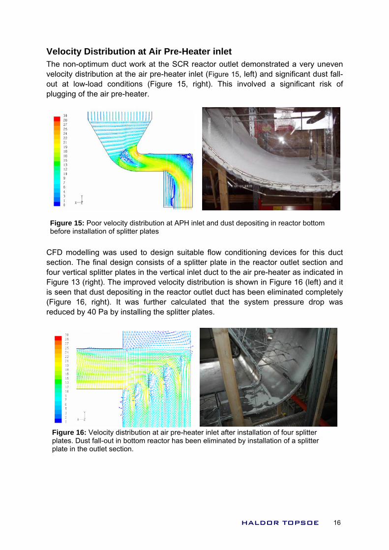
Velocity Distribution at Air Pre-Heater inlet The non-optimum duct work at the SCR reactor outlet demonstrated a very uneven velocity distribution at the air pre-heater inlet (Figure 15, left) and significant dust fall-out at low-load conditions (Figure 15, right). This involved a significant risk of plugging of the air pre-heater.
Figure 15: Poor velocity distribution at APH inlet and dust depositing in reactor bottom before installation of splitter plates
CFD modelling was used to design suitable flow conditioning devices for this duct section. The final design consists of a splitter plate in the reactor outlet section and four vertical splitter plates in the vertical inlet duct to the air pre-heater as indicated in Figure 13 (right). The improved velocity distribution is shown in Figure 16 (left) and it is seen that dust depositing in the reactor outlet duct has been eliminated completely (Figure 16, right). It was further calculated that the system pressure drop was reduced by 40 Pa by installing the splitter plates.
Figure 16: Velocity distribution at air pre-heater inlet after installation of four splitter plates. Dust fall-out in bottom reactor has been eliminated by installation of a splitter plate in the outlet section.
HALDOR TOPSOE 16
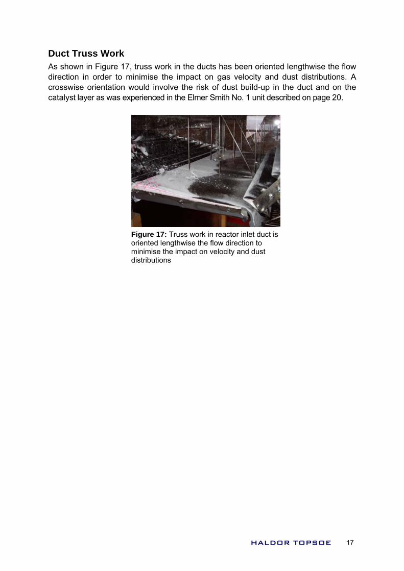
Duct Truss Work As shown in Figure 17, truss work in the ducts has been oriented lengthwise the flow direction in order to minimise the impact on gas velocity and dust distributions. A crosswise orientation would involve the risk of dust build-up in the duct and on the catalyst layer as was experienced in the Elmer Smith No. 1 unit described on page 20.
Fomd
igure 17: Truss work in reactor inlet duct is riented lengthwise the flow direction to inimise the impact on velocity and dust istributions
HALDOR TOPSOE 17
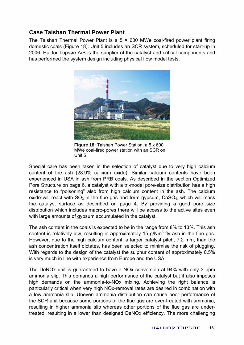
Case Taishan Thermal Power Plant The Taishan Thermal Power Plant is a 5 × 600 MWe coal-fired power plant firing domestic coals (Figure 18). Unit 5 includes an SCR system, scheduled for start-up in 2006. Haldor Topsøe A/S is the supplier of the catalyst and critical components and has performed the system design including physical flow model tests.
Figure 18: Taishan Power Station, a 5 x 600 MWe coal-fired power station with an SCR on Unit 5
Special care has been taken in the selection of catalyst due to very high calcium content of the ash (28.9% calcium oxide). Similar calcium contents have been experienced in USA in ash from PRB coals. As described in the section Optimized Pore Structure on page 6, a catalyst with a tri-modal pore-size distribution has a high resistance to “poisoning” also from high calcium content in the ash. The calcium oxide will react with SO3 in the flue gas and form gypsum, CaSO4, which will mask the catalyst surface as described on page 4. By providing a good pore size distribution which includes macro-pores there will be access to the active sites even with large amounts of gypsum accumulated in the catalyst.
The ash content in the coals is expected to be in the range from 8% to 13%. This ash content is relatively low, resulting in approximately 15 g/Nm3 fly ash in the flue gas. However, due to the high calcium content, a larger catalyst pitch, 7.2 mm, than the ash concentration itself dictates, has been selected to minimise the risk of plugging. With regards to the design of the catalyst the sulphur content of approximately 0.5% is very much in line with experience from Europe and the USA.
The DeNOx unit is guaranteed to have a NOx conversion at 94% with only 3 ppm ammonia slip. This demands a high performance of the catalyst but it also imposes high demands on the ammonia-to-NOx mixing. Achieving the right balance is particularly critical when very high NOx-removal rates are desired in combination with a low ammonia slip. Uneven ammonia distribution can cause poor performance of the SCR unit because some portions of the flue gas are over-treated with ammonia, resulting in higher ammonia slip whereas other portions of the flue gas are under-treated, resulting in a lower than designed DeNOx efficiency. The more challenging
HALDOR TOPSOE 18
the NOx reduction and ammonia slip requirements, the less deviation from perfect mixing is permitted.
To ensure optimal mixing the distance from the ammonia injection grid to the catalyst should be as long as possible. However, this is costly and therefore static mixers are often introduced in the flue gas. A drawback of static mixers is that they introduce an additional pressure loss which is not desirable.
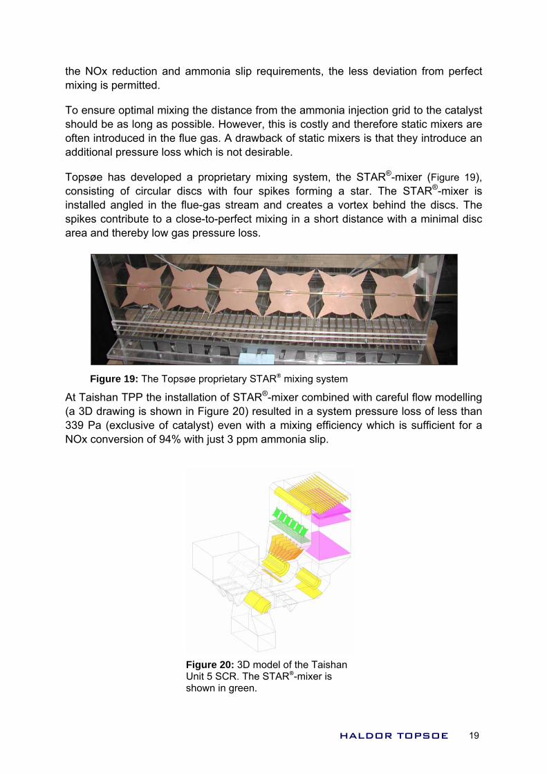
Topsøe has developed a proprietary mixing system, the STAR®-mixer (Figure 19), consisting of circular discs with four spikes forming a star. The STAR®-mixer is installed angled in the flue-gas stream and creates a vortex behind the discs. The spikes contribute to a close-to-perfect mixing in a short distance with a minimal disc area and thereby low gas pressure loss.
Figure 19: The Topsøe proprietary STAR® mixing system
At Taishan TPP the installation of STAR®-mixer combined with careful flow modelling (a 3D drawing is shown in Figure 20) resulted in a system pressure loss of less than 339 Pa (exclusive of catalyst) even with a mixing efficiency which is sufficient for a NOx conversion of 94% with just 3 ppm ammonia slip.
Figure 20: 3D model of the Taishan Unit 5 SCR. The STAR®-mixer is shown in green.
HALDOR TOPSOE 19
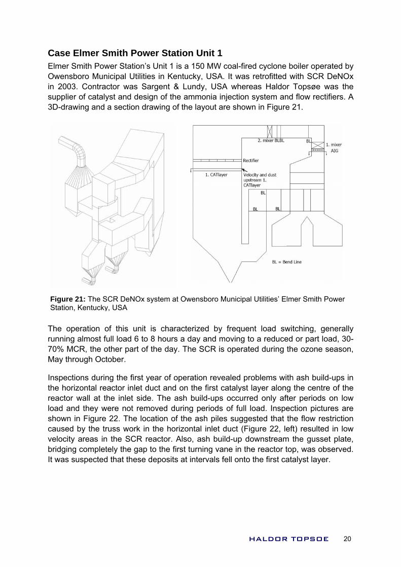
Case Elmer Smith Power Station Unit 1 Elmer Smith Power Station’s Unit 1 is a 150 MW coal-fired cyclone boiler operated by Owensboro Municipal Utilities in Kentucky, USA. It was retrofitted with SCR DeNOx in 2003. Contractor was Sargent & Lundy, USA whereas Haldor Topsøe was the supplier of catalyst and design of the ammonia injection system and flow rectifiers. A 3D-drawing and a section drawing of the layout are shown in Figure 21.
Figure 21: The SCR DeNOx system at Owensboro Municipal Utilities’ Elmer Smith Power Station, Kentucky, USA
The operation of this unit is characterized by frequent load switching, generally running almost full load 6 to 8 hours a day and moving to a reduced or part load, 30-70% MCR, the other part of the day. The SCR is operated during the ozone season, May through October.
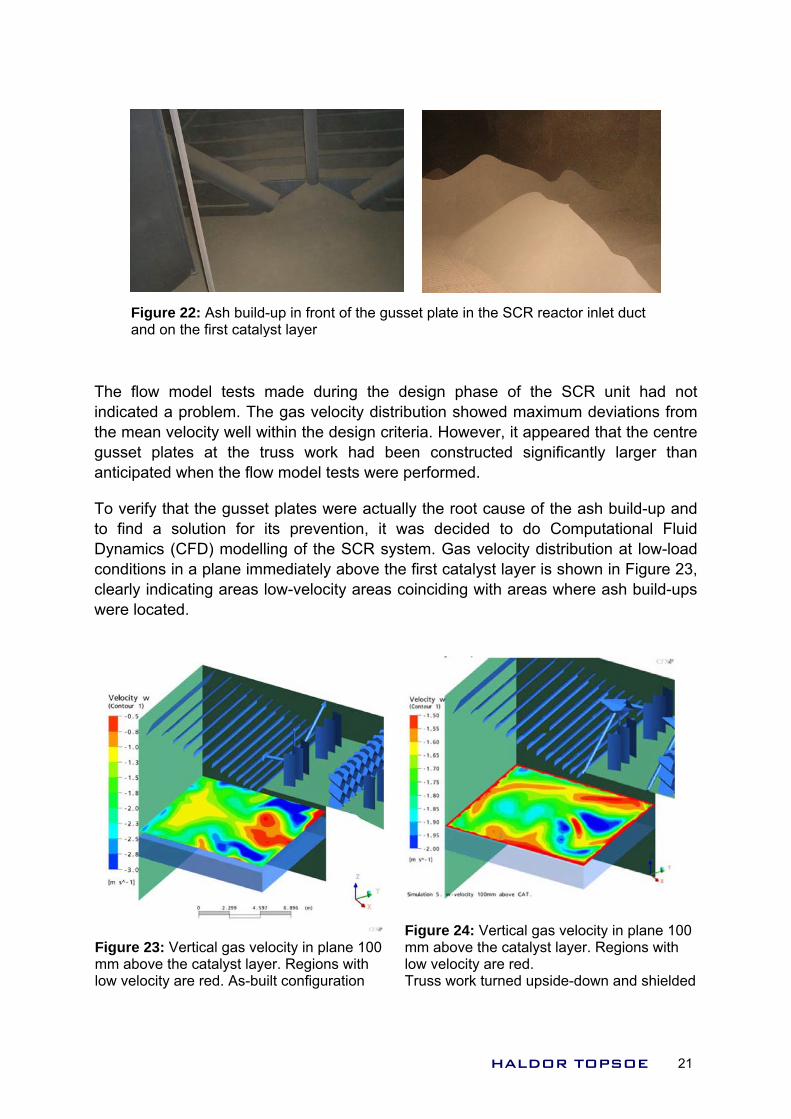
Inspections during the first year of operation revealed problems with ash build-ups in the horizontal reactor inlet duct and on the first catalyst layer along the centre of the reactor wall at the inlet side. The ash build-ups occurred only after periods on low load and they were not removed during periods of full load. Inspection pictures are shown in Figure 22. The location of the ash piles suggested that the flow restriction caused by the truss work in the horizontal inlet duct (Figure 22, left) resulted in low velocity areas in the SCR reactor. Also, ash build-up downstream the gusset plate, bridging completely the gap to the first turning vane in the reactor top, was observed. It was suspected that these deposits at intervals fell onto the first catalyst layer.
HALDOR TOPSOE 20
The flow model tests made during the design phase of the SCR unit had not indicated a problem. The gas velocity distribution showed maximum deviations from the mean velocity well within the design criteria. However, it appeared that the centre gusset plates at the truss work had been constructed significantly larger than anticipated when the flow model tests were performed.
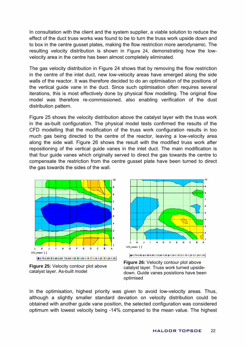
To verify that the gusset plates were actually the root cause of the ash build-up and to find a solution for its prevention, it was decided to do Computational Fluid Dynamics (CFD) modelling of the SCR system. Gas velocity distribution at low-load conditions in a plane immediately above the first catalyst layer is shown in Figure 23, clearly indicating areas low-velocity areas coinciding with areas where ash build-ups were located.
Figure 23: Vertical gas velocity in plane 100 mm above the catalyst layer. Regions with low velocity are red. As-built configuration
Figure 24: Vertical gas velocity in plane 100 mm above the catalyst layer. Regions with low velocity are red. Truss work turned upside-down and shielded
Figure 22: Ash build-up in front of the gusset plate in the SCR reactor inlet duct and on the first catalyst layer
HALDOR TOPSOE 21
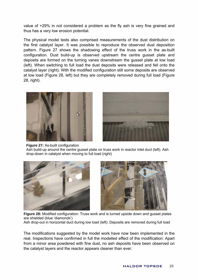
In consultation with the client and the system supplier, a viable solution to reduce the effect of the duct truss works was found to be to turn the truss work upside down and to box in the centre gusset plates, making the flow restriction more aerodynamic. The resulting velocity distribution is shown in Figure 24, demonstrating how the low-velocity area in the centre has been almost completely eliminated.
The gas velocity distribution in Figure 24 shows that by removing the flow restriction in the centre of the inlet duct, new low-velocity areas have emerged along the side walls of the reactor. It was therefore decided to do an optimisation of the positions of the vertical guide vane in the duct. Since such optimisation often requires several iterations, this is most effectively done by physical flow modelling. The original flow model was therefore re-commissioned, also enabling verification of the dust distribution pattern.
Figure 25 shows the r with the truss work in the as-built configu med the results of the CFD modelling that t fig tion results in too much gas being directed to the centre of the reactor, leaving a low-velocity area along the side wall. Figure 26 shows the result with the modified truss work after repositioning of the vertical guide vanes in the inlet duct. The main modification is that four guide vanes which originally served to direct the gas towards the centre to compensate the restriction from the centre gusset plate have been turned to direct the gas towards the sides of the wall.
velocity distribution above the catalyst layeration. The physical model tests confirhe modification of the truss work con ura
Figure 26: Velocity contour plot above catalyst layer. Truss work turned upside-down. Guide vanes posistiooptimised
ns have been Figure 25: Velocity contour plot above catalyst layer. As-built model
In the optimisation, highest priority was given to avoid low-velocity areas. Thus, although a slightly smaller standard deviation on velocity distribution could be obtained with another guide vane position, the selected configuration was considered optimum with lowest velocity being -14% compared to the mean value. The highest
HALDOR TOPSOE 22
value of +29% in not considered a problem as the fly ash is very fine grained and thus has a very low erosion potential.
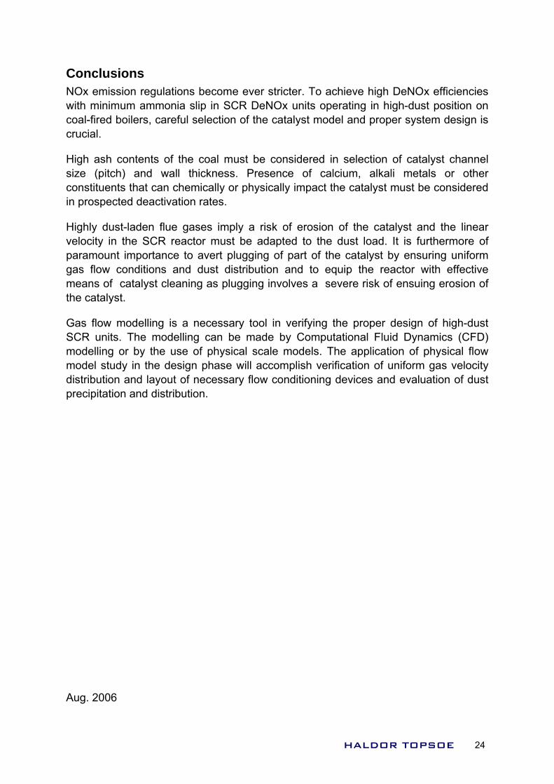
The physical model tests also comprised measurements of the dust distribution on the first catalyst layer. It was possible to reproduce the observed dust deposition pattern. Figure 27 shows the shadowing effect of the truss work in the as-built configuration. Dust build-up is observed upstream the centre gusset plate and deposits are formed on the turning vanes downstream the gusset plate at low load (left). When switching to full load the dust deposits were released and fell onto the catalyst layer (right). With the modified configuration still some deposits are observed at low load (Figure 28, left) but they are completely removed during full load (Figure 28, right).
Figure 27: As-built configuration Ash build-up around the centre gusset plate on truss work in reactor inlet duct (left). Ash drop-down in catalyst when moving to full load (right)
The modifications suggested by the model work have now been implemented in the real. Inspections have confirmed in full the modelled effect of the modification: Apart from a minor area powdered with fine dust, no ash deposits have been observed on the catalyst layers and the reactor appears cleaner than ever.
Figure 28: Modified configuration: Truss work and is turned upside down and gusset plates are shielded (blue ‘diamonds’) Ash drop-out in horizontal duct during low load (left). Deposits are removed during full load
HALDOR TOPSOE 23
Conclusions NOx emission regulations become ever stricter. To achieve high DeNOx efficiencies with minimum ammonia slip in SCR DeNOx units operating in high-dust position on coal-fired boilers, careful selection of the catalyst model and proper system design is crucial.
High ash contents of the coal must be considered in selection of catalyst channel size (pitch) and wall thickness. Presence of calcium, alkali metals or other constituents that can chemically or physically impact the catalyst must be considered in prospected deactivation rates.
H ply a risk of erosion of the catalyst and the linear v of p the catalyst by ensuring uniform gas flow conditions and dust distribution and to equip the reactor with effective means of catalyst cleaning as plugging involves a severe risk of ensuing erosion of the catalyst.
Gas flow modelling is a necessary tool in verifying the proper design of high-dust SCR units. The modelling can be made by Computational Fluid Dynamics (CFD) modelling or by the use of physical scale models. The application of physical flow model study in the design phase will accomplish verification of uniform gas velocity distribution and layout of necessary flow conditioning devices and evaluation of dust precipitation and distribution.
Aug. 2006
ighly dust-laden flue gases imelocity in the SCR reactor must be adapted to the dust load. It is furthermore aramount importance to avert plugging of part of
HALDOR TOPSOE 24