implementation of segment routing and mpls traffic ... · segment routing using mpls data plane,...
TRANSCRIPT

POLITECNICO DI MILANO
Dipartimento di Elettronica, Informazione e Bioingegneria
Master of Science
Telecommunications Engineering
IMPLEMENTATION OF SEGMENT ROUTING AND
MPLS TRAFFIC ENGINEERING IN SOFTWARE-
DEFINED NETWORK BASED ON GNS3 NETWORK
EMULATOR AND OPENDAYLIGHT SDN CONTROLLER
Author:
Seyed Mohammad Javad Yasini
Supervisor:
Prof. Maier Guido Alberto
853629
2015-2018

Seyed Mohammad Javad Yasini Master Thesis
2
Abstract
Segment routing is a technology that is gaining popularity for simplifying Multi-protocol
Label Switching (MPLS) networks. It has the benefits of interfacing with software-
defined network. SDN is already well-established paradigm in the industry, making it
easier to manage the network.
Segment Routing is the source-routing paradigm addressing existing drawbacks of
MPLS networks in terms of simplicity, scalability and manageability. Nowadays network
operators are demanding more flexible, agile, scalable, and simple network
architectures. These architectures will help them to implement application-centric
networking and cloud-based services, which are increasingly demanded functionalities
on the market. Segment Routing was created to address this very issue and evolve
network in the era of Software Defined Networking.
Ability to engineer traffic flows with such granularity can give network service provider
great business benefits. Segment Routing makes it easy to address customer’s
dynamic traffic requirements from high-level application.
This thesis work presents a comprehensive comparison between MPLS and Segment
Routing Traffic Engineering, also Implementation of both technologies in an SDN
network environment, based on GNS3 network Emulator as data network Layer,
OpenDayLight as SDN Controller, and Python scripts for retrieving Segment IDs as a
part of network Orchestrator in Application Layer.

Seyed Mohammad Javad Yasini Master Thesis
3
Contents
Chapter 1. Introduction ................................................................................................................................ 5
Chapter 2. Related Works ............................................................................................................................ 7
Chapter 3. Technology Overview ................................................................................................................. 8
3.1 Segment Routing ................................................................................................................................ 8
3.1.1 Segment Routing Concepts ....................................................................................................... 11
3.1.2 Segment Routing Use Cases ...................................................................................................... 17
3.2 Multi-Protocol Label Switching ........................................................................................................ 20
3.3 Segment Routing vs. MPLS............................................................................................................... 21
Chapter 4. Operating Environment ........................................................................................................... 24
4.1 Software Defined Networks ............................................................................................................ 24
4.1.1 The SDN architecture ................................................................................................................ 26
4.1.2 Benefits of SDN .......................................................................................................................... 27
4.2 Segment routing and SDN ................................................................................................................ 28
4.3 OpenDaylight .................................................................................................................................... 29
4.4 GNS3 ................................................................................................................................................. 32
4.5 Cisco IOS XRv .................................................................................................................................... 32
Chapter 5. Implementation of MPLS-TE and SR-TE Scenarios .................................................................. 33
5.1 Implementation Overview ............................................................................................................... 33
1) Getting the image ........................................................................................................................ 35
2) Extracting the OVA file ................................................................................................................ 35
3) Convert vmdk to qcow2 .............................................................................................................. 35
4) Create a new Qemu VM in GNS3 ............................................................................................. 36
5) Finalizing the VM settings .......................................................................................................... 38
6) Booting up the router ................................................................................................................... 40
5.2 Environment Setup ........................................................................................................................... 41
5.2.1 Network Build-Up ...................................................................................................................... 41
5.2.2 OpenDaylight Setup ........................................................................................................... 42
5.2.3 Web Based REST API client ....................................................................................................... 42
5.3 Network Configuration .............................................................................................................. 43

Seyed Mohammad Javad Yasini Master Thesis
4
5.4 OpenDaylight Configuration ...................................................................................................... 50
5.5 MPLS-TE and SR-TE Tunnel Setup by OpenDayLight ................................................................. 51
5.5.1 MPLS-TE Tunnel Setup ....................................................................................................... 51
5.5.2 Segment routing-TE Tunnel Setup .................................................................................. 54
Chapter 6. Preparation of Input data for segment routing Application in Network orchestrator .......... 58
6.1 Retrieving SIDs by NETCONF form routers ................................................................................ 58
6.2 Retrieving SIDs from BGP RIB in OpenDayLight ........................................................................... 61
7 Conclusion .......................................................................................................................................... 63
8 Acknowledgements ............................................................................................................................... 64
References .................................................................................................................................................. 65

Seyed Mohammad Javad Yasini Master Thesis
5
Chapter 1. Introduction
This work, as an experimental thesis, is showing that how can we achieve a simpler
traffic engineering technic, using segment routing technology, while addressing Multi-
protocol Label Switching (MPLS) traffic engineering weaknesses. As one of the key
advantages of Segment Routing is its simplicity, in this work I am confirming that It only
takes few lines of configuration to enable it on the routers which are already a part of
MPLS network. Starting from an MPLS network, and step by step presentation of how
Segment Routing can be deployed in the network, and then by showing that there is no
need to make massive upgrades inside the network, I emphasized the fact that how
simply the migration can be done, and what benefits can be achieved. Segment routing
can be integrated with existing MPLS network since it is interoperable with existing
MPLS control and data planes.
One of the main goals of this work is the usage of GNS3 network emulator as a free
platform with almost no drawback comparing to two other previous ways which were
commonly tried by other researchers. The first way of network implementation which
was mostly used, is to implement routers on stand-alone virtual machines. By doing so,
first, there are some complication added to the network by not having a whole topology
of the network in front of you. Consequently, there should be a painted topology of the
network containing routers, links, and there is no possibility to define and modify
network links parameters (jitter, packet loss delay etc.) and a lot of other features that
can be seen in GNS3 environment.
The second way of network topology implementation was to use Cisco Virl platform.
The main reason exceling GNS3 to Virl is that you must pay for Virl but GNS3 is free.
So, trying this project on GNS3 can provide a great opportunity for future researchers

Seyed Mohammad Javad Yasini Master Thesis
6
who are seeking to try their scenarios on a free software, and not willing to pay for such
experimental research works.
Segment routing makes the establishment and management of traffic engineering
tunnels easier, by defining the path of the tunnel by the series of Segment Identifiers
(SIDs) which our flows should traverse through the network. This path computation is
done in SDN Controller, but the configuration enforcement should be carried out from
application layer at the top of controller and as a part of network orchestrator. The main
input data for this application (considering that we have already the Management IP
addresses of the whole routers in the network) is corresponding segment ID for each
node. In this work, I will describe two different ways for retrieving SID numbers out of
router’s configuration and BGP-RIB in OpenDayLight SDN Controller. The result would
be stored in mongoDB as a text-based database which presents all the necessary
information and makes it available for a segment routing application.
My thesis presents the research about Segment Routing and discusses its underlying
technologies (MPLS, SDN) and protocols (BGP, BGP-IS, IS-IS, PCEP). The listed
protocols are essential for Segment Routing.
In my thesis I brought together all above mentioned tools and protocols to provide
implementation of Segment Routing inside Cisco routers running in GNS3.
In the second chapter of this work, I introduced some related similar works which have
been done before.
During third chapter, you can find main segment routing concepts and use cases,
description of MPLS technology, and finally comparison between segment routing and
MPLS traffic engineering.
In the forth chapter, SDN definition and architecture is described. I described segment
routing in SDN. Then OpenDayLight as SDN controller, GNS3 as data network layer
platform, and Cisco XRv as routers which are segment routing capable are presented
as platforms used for this experimental project.

Seyed Mohammad Javad Yasini Master Thesis
7
During the fifth chapter, I presented implementation steps in different layers, and I
explained applications used for testing necessary scenarios. ODL configuration, routers
configuration, GNS3 and postman as REST client application are also presented in this
chapter. At the end of this chapter, I mentioned how to setup MPLS and Segment
routing tunnels with some detailed examples.
In chapter sixth, I explained how we can retrieve information, directly from routers by
Netconf protocol, or from data modules inside SDN controller, to use in segment routing
application which we can implement as a part of network orchestrator.
Chapter 2. Related Works
Segment routing Implementation has been already done by some research groups
through companies and universities. Here, first, I am going to explain new achievements
in this thesis, by comparing to some other previous works which are already done in
segment routing field.
This work can be considered as the Future work of Miss. Ana Kos Thesis named as:
“Segment Routing Principles and Applications for SDN” [1], in which ECMP segment
routing and Multi-domain segment routing scenarios were analyzed.
The shift from legacy networks with distributed control plane to Software Defined
Networks can be painful for ISPs. SDN interoperability with legacy devices attracted
huge attention in networking world. However, existing employments of SDN are still
limited and existing prototypes are still premature to offer confidence to real world
deployment. It is certain that SDN adoption will come incrementally in the close future.
Work [2] is the one of the first scientific researches that investigates the network
performance issue by migrating from traditional to SDN network. The work is focused on
cooperation between SDN-capable forwarding elements and legacy equipment. The

Seyed Mohammad Javad Yasini Master Thesis
8
results have shown that improvements come even by employing a few strategically
placed SDN forwarding elements into legacy network.
Chapter 3. Technology Overview
This chapter explains concepts and use cases of Segment Routing in more detailed
manner. Moreover, one can find analysis of all protocols and technologies necessary for
Segment Routing deployment.
3.1 Segment Routing
Many of today’s MPLS networks are built with Traffic Engineering (TE)capabilities. With
MPLS Traffic Engineering, a network operator can optimize and make better use of its
IP/MPLS network infrastructure. TE helps in congestion avoidance, Provides Fast
Reroute (FRR) in case of link failure, and allows a head-end router to re-optimize an
existing TE tunnel path by using newly available resources. All of this helps enhance the
performance of an MPLS label switched path (LSP).
Currently, the go-to technology for network operators to build traffic engineered MPLS
networks is RSVP-TE. But today, we are seeing the adoption of another protocol that
not only helps enable traffic engineering but can also be used by software-defined
networking (SDN) applications to automatically provision new paths.
MPLS-TE already exists as traffic engineering solution. However, it has drawbacks in
terms of scalability, manageability, and uses heavy signaling protocols such as RSVP-
TE and LDP. Segment Routing overcomes these drawbacks and enables network
service providers to change network behavior dynamically.

Seyed Mohammad Javad Yasini Master Thesis
9
Segment Routing (SR) is a new source routing paradigm. It is a network technology that
wants to address several drawbacks of existing IP/MPLS networks in terms of
scalability, simplicity, and ease of operation [1]. Segment Routing is a basis of
application engineered routing. Application engineered routing is a new business model
that can enable applications to direct behavior of network. It is a paradigm designed and
built for SDN era.
Segment Routing is being standardized by Internet Engineering Task Force under
Source Packet Routing in Networking (SPRING) group [28].
Segment Routing enhances packet-forwarding behavior. It allows network to carry
packets via specific forwarding path. This path can be different from natural shortest
path that packet usually takes inside the network. Having control to set up custom
forwarding paths opens up much use case scenarios that certain applications can
benefit from.
Source-based routing is not a brand-new idea in the world of networking, but it has not
seen widespread adoption. A node (usually a router or a switch), which steers packets
using list of ordered instructions is called segment.
Today’s traffic engineering solutions, such as Resource Reservation Protocol– Traffic
Engineering (RSVP-TE) requires signaling for each path, and state of each path needs
to be present on each node that traffic traverses. Segment Routing can implement all
these without the need of signaling protocol, making its architecture simpler and more
scalable.
Segment Routing using MPLS data plane, does not require Label Distribution Protocol
(LDP) or RSVP-TE. Labels are distributed using Interior Gateway Protocol either
Intermediate System-to-Intermediate System (ISIS) or Open Shortest Path First (OSPF)
and BGP. Running fewer protocols inside the network already makes network more
stable and scalable. Segment Routing paths are protected with Fast Reroute (FRR)
capability, that allows rerouting of traffic in under 50 milliseconds, in case of link or node
failure.

Seyed Mohammad Javad Yasini Master Thesis
10
Traditionally routers guide traffic inside the network primarily based on destination IP.
Underlying Interior Gateway Protocol (IGP) was used to distribute network topology and
compute shortest path from ingress to egress node. However, nowadays packet loss,
jitter, delay, and available bandwidth have become major business differentiator when
creating service-level agreements (SLAs). Therefore, this new business requirements
are pushing networks to evolve towards more agility and flexibility.
Multiprotocol Label Switching (MPLS) introduced tunneling mechanism and traffic
steering functions [3]. These were main reasons behind success of the MPLS
technology. MPLS introduced MPLS based Virtual Private Networks (VPN).
However, Resource Reservation Protocol-Traffic Engineering (RSVP-TE) did not have
same popularity as MPLS VPN. One of the main reasons of this was having poor load
balancing characteristics. Another reason was that it was not very scalable. Final
reason was that computation was distributed and this was causing some unpredictable
traffic patterns and not optimal use of resources.
Target audience for Segment routing are mainly Internet Service Providers (ISP),
content providers, over-the-top (OTT) providers, large enterprises, data centers, and
others.
However, to achieve this some tools and protocols needs to be present and enabled
inside the network. In particular: SDN controller and protocols such as BGP, BGP-LS,
IGP (IS-IS), PCEP, MPLS with Segment Routing.
SDN controller is needed to have a global view of the network, communicate messages
and commands back and forth with network devices. It acts as a medium between high-
level application and network devices.
BGP-LS and IGP protocols are needed to extract link state information from the
network. This data includes link bandwidth, metric, delay, and more. This data is readily
accessible by SDN controller, and therefore by high-level application.

Seyed Mohammad Javad Yasini Master Thesis
11
Path Computation Element (PCEP) needs to be present in the network in order to
calculate suitable paths and then push the path onto the network node using SDN
controller.
Segment Routing can enable traffic engineering in three possible ways:
• By manually creating Segment Routing Label Switched Paths and explicitly
defining route inside the network. This equivalent of MPLS-TE but without extra
protocols
• By manually creating Segment Routing tunnels. Path is calculated by Path
Computation Element (PCE) and later pushed by SDN Controller onto the
network
• Dynamically create Segment Routing tunnels. Path is calculated by PCE using
existing network information or SLA, such as delay, bandwidth, metric etc.
Segment Routing (SR) is not a new technology but only recently has it been embraced
by all the major network equipment vendors. It is a packet forwarding technology where
the source node defines the path for traffic, which is then sent through specific nodes
and forwarding paths called segments. An SR path is not dependent on hop-by-hop
signaling, Label Distribution Protocol (LDP) or RSVP. Instead, it uses segments for
forwarding.
3.1.1 Segment Routing Concepts
This subchapter discusses main Segment Routing concepts. Firstly, a concept of
segment will be explained. After, the classification of segments will be represented with
related examples.
Segment

Seyed Mohammad Javad Yasini Master Thesis
12
According to the IETF, a segment is an instruction that node executes on the incoming
packet. This instruction could be for instance, forward the packet to a specific network
node according to shortest path, or forward packet through specific interface or deliver
the packet to a given application or service.
Segment is identified with Segment Identifier (SID) and in MPLS environment it is
encoded in 32 bits MPLS label [5].
Segment Advertising
Segments are advertised using IGP and BGP routing protocols. For both protocol types,
Segment Routing extensions are defined to include Segment Routing information. In
other words, routing protocols enable segments’ signaling through the network. Let us
now consider an autonomous system consisting of multiple IGP areas. Within each IGP
area either IS-IS or OSPF is running. They are responsible to advertise segments within
an IGP domain. However, in order to implement traffic engineering between an AS,
segment exchanging between BGP peers must be enabled. BGP is extended to
advertise the segments related to the BGP-prefix.
Segment routing is constructed with SDN in mind. In software defined network it is
assumed that SDN controller is in charge of determining end-to-end paths throughout a
network. SDN has information on underlying network topology provided by BGP-LS
protocol. In a software defined network that implements Segment Routing, BGP-LS is
responsible to advertise SDN controller about segment identifiers. The topological path
calculated by a SDN controller is pushed down to the source node in a form of the list of
segments. Calculated path is carried by PCEP protocol. In SDN environment both
PCEP and BGPLS extensions are necessary to support Segment Routing.
Global and Local Segments
According to its significance in the network all the segments can be divided on global
and local. For now, the term network will be related to an IGP area. Global segment is
related to the instruction that is supported by all nodes in an IGP domain. A global

Seyed Mohammad Javad Yasini Master Thesis
13
segment must be unique within a domain. Any node in an IGP domain must have all
global segments in its Forwarding Information Base (FIB). The value of global segment
identifiers is taken from the Segment Routing Global Block (SRGB). SRGB is a
subspace of a 32bit SID space, and it takes values from 16000 up to 23999 [6].
Local segment is an instruction that is supported by the node originating it. Local
segments take a value outside of SRGB range. Since it has only local significance, its
value is related only to local router FIB. A router is not aware of local segments of the
other routers in a domain. Moreover, the local SID values could be reused within an IGP
domain, since a local SID value has local meaning for each single router.
IGP Segment Identifiers – IGP-SIDs
Link state protocols have an important role in Segment Routing. Global and local
segments are distributed throughout the domain using IGP [5]. Both Open Shortest Path
First (OSPF) and Intermediate System to Intermediate System (IS-IS) support Segment
Routing thanks to well-defined protocol extensions. Segment Identifiers
distributed by an IGP can be classified as it is shown in the following figure:
Prefix-SID
In general, Prefix-SID is a segment that refers to a specific network prefix. Prefix-SID is
always global within an IGP domain and it refers to the shortest path computed by IGP
to the related prefix. A packet that enters an IGP area with an active Prefix-SID will be
forwarded along the ECMP-aware shortest path to the prefix. Since a prefix could
Seyed Mohammad Javad Yasini Master Thesis
14
represent a node or a group of nodes within an IGP domain, Prefix-SIDs are further
divided into Node-SIDs and Anycast-SIDs:
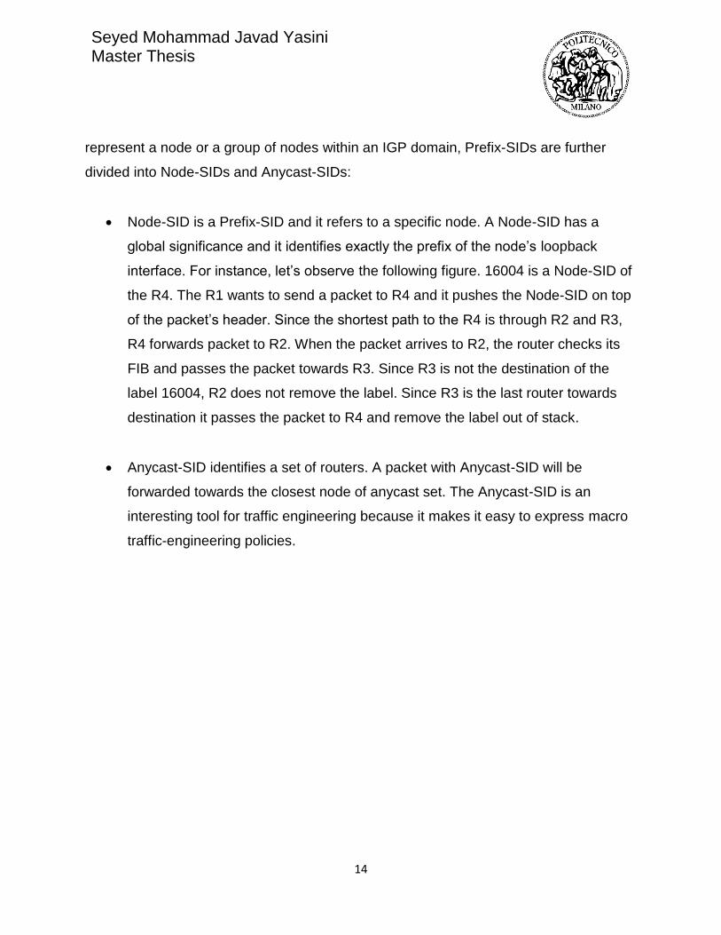
• Node-SID is a Prefix-SID and it refers to a specific node. A Node-SID has a
global significance and it identifies exactly the prefix of the node’s loopback
interface. For instance, let’s observe the following figure. 16004 is a Node-SID of
the R4. The R1 wants to send a packet to R4 and it pushes the Node-SID on top
of the packet’s header. Since the shortest path to the R4 is through R2 and R3,
R4 forwards packet to R2. When the packet arrives to R2, the router checks its
FIB and passes the packet towards R3. Since R3 is not the destination of the
label 16004, R2 does not remove the label. Since R3 is the last router towards
destination it passes the packet to R4 and remove the label out of stack.
• Anycast-SID identifies a set of routers. A packet with Anycast-SID will be
forwarded towards the closest node of anycast set. The Anycast-SID is an
interesting tool for traffic engineering because it makes it easy to express macro
traffic-engineering policies.
Seyed Mohammad Javad Yasini Master Thesis
15
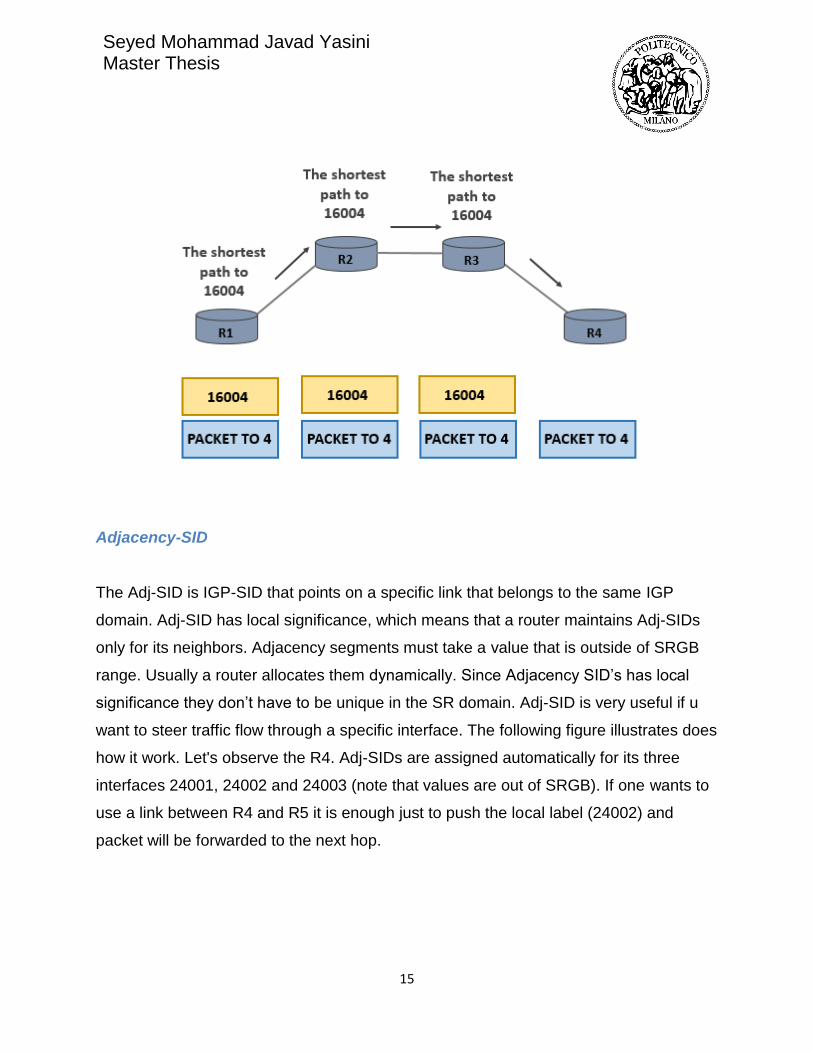
Adjacency-SID
The Adj-SID is IGP-SID that points on a specific link that belongs to the same IGP
domain. Adj-SID has local significance, which means that a router maintains Adj-SIDs
only for its neighbors. Adjacency segments must take a value that is outside of SRGB
range. Usually a router allocates them dynamically. Since Adjacency SID’s has local
significance they don’t have to be unique in the SR domain. Adj-SID is very useful if u
want to steer traffic flow through a specific interface. The following figure illustrates does
how it work. Let's observe the R4. Adj-SIDs are assigned automatically for its three
interfaces 24001, 24002 and 24003 (note that values are out of SRGB). If one wants to
use a link between R4 and R5 it is enough just to push the local label (24002) and
packet will be forwarded to the next hop.
Seyed Mohammad Javad Yasini Master Thesis
16
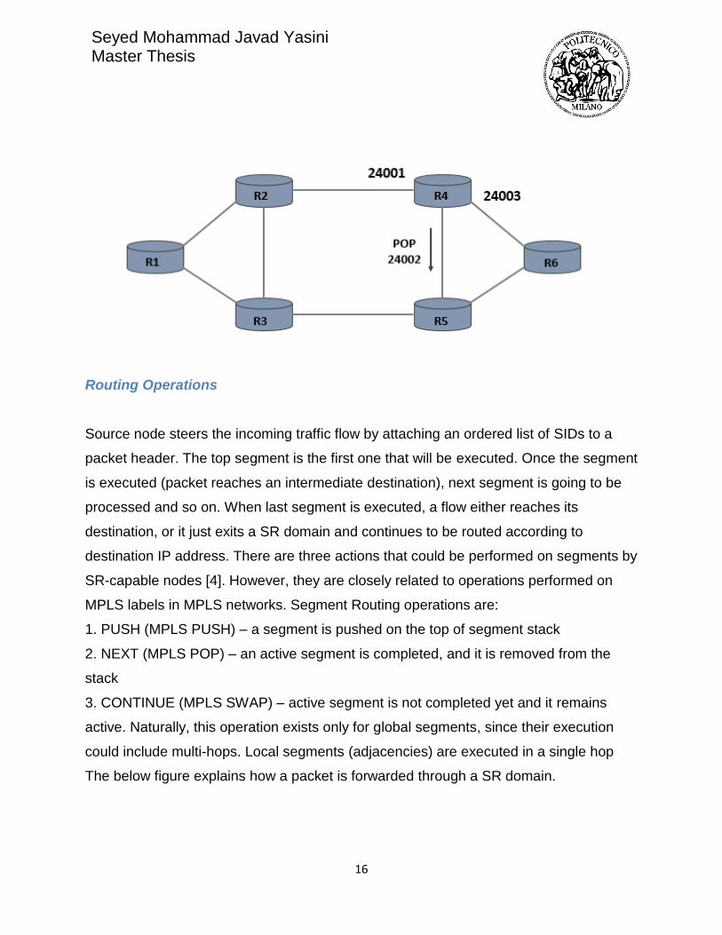
Routing Operations
Source node steers the incoming traffic flow by attaching an ordered list of SIDs to a
packet header. The top segment is the first one that will be executed. Once the segment
is executed (packet reaches an intermediate destination), next segment is going to be
processed and so on. When last segment is executed, a flow either reaches its
destination, or it just exits a SR domain and continues to be routed according to
destination IP address. There are three actions that could be performed on segments by
SR-capable nodes [4]. However, they are closely related to operations performed on
MPLS labels in MPLS networks. Segment Routing operations are:
1. PUSH (MPLS PUSH) – a segment is pushed on the top of segment stack
2. NEXT (MPLS POP) – an active segment is completed, and it is removed from the
stack
3. CONTINUE (MPLS SWAP) – active segment is not completed yet and it remains
active. Naturally, this operation exists only for global segments, since their execution
could include multi-hops. Local segments (adjacencies) are executed in a single hop
The below figure explains how a packet is forwarded through a SR domain.

Seyed Mohammad Javad Yasini Master Thesis
17
3.1.2 Segment Routing Use Cases
Simplified transport of MPLS services
Segment Routing can offer the same tunneling service as MPLS in simplified manner
using just IS-IS or OSPF. Service provider can easily enable services like L3VPN, VPLS
and VPWS by setting up a Node-SID per network edge and ECMP tunnels will be
created automatically from any ingress to any egress edge [1]. LDP and RSVP are no
more required, and that leads to following benefits:
• Simpler operation – less signaling in the network meaning the gain in terms of
bandwidth and operation complexity
• Scaling – only one label for each node, reducing number of LSDB entries

Seyed Mohammad Javad Yasini Master Thesis
18
Segment Routing and LDP coexistence
Inside MPLS Architecture, Segment Routing can coexist with LDP and RSVPTE [1] [7].
Segment Routing Global Block assures that labels used for Segment Routing and LDP
are allocated from different blocks of label. If both Segment Routing and LDP are
enabled on the same router, LDP is given priority by default, but this can be changed
using CLI configuration.
Traffic Engineering
Segment Routing can create tunnels according to customers’ needs. SR enables traffic
steering through any desired network path. By employing different SIDs, tunnels can be
constructed in a smart way, which will result in increased network performance and
throughput. Also, tunnels can be designed by considering customers’ SLAs. The most
significant TE use cases are presented below.
Deterministic path or path avoidance is for sure the most useful tool in traffic
engineering [8]. By exploiting adjacency SIDs, one can specify a path as path which
flow will take through the network. Typical use case is presented on the below picture.

Seyed Mohammad Javad Yasini Master Thesis
19
One wants to send the traffic to R6 (Node-SID 16006). The easiest way to it is to push
node segment on top of the packet and it will be forwarded according to the shortest
path. However, Node-SID represents the instruction for ECMP-aware shortest path to
R6, meaning that flow will take either R1-R2-R4-R6 or R1-R3-R5-R6. In the case the
link R1-R2 becomes overloaded and the QoS drops down, a controller can dynamically
push the traffic to R3 and avoid a busy link. Traffic will arrive at R3 and then it will
continue to R6 according to the shortest path.
By assigning anycast SIDs, one can define a group of routers which flow will take on its
way to the destination. For service providers this is very interesting tool because it can
express macro policies such as “go via plane one of dual plane network” or “go via
European Region” [9]. As an example, let’s observe the following figure. The network
can be described as a dual plane. One can steer the traffic only through yellow or blue
nodes to the final destination by assigning labels {16001, 16005} or {16002, 16005}.
ECMP is supported within a plain, meaning if there are disjoint paths, the load will be
balanced (per flow).The main benefits are tunneling without RSVP and LDP signaling,
ECMP-aware routing and zero per-flow state on transient routers. Only additional

Seyed Mohammad Javad Yasini Master Thesis
20
anycast SID have to be configured (one per network plane).
Fast Reroute
Segment Routing supports services with tight SLA. To do so, Topology Independent
Loop-Free Alternate (TI-LFA) is used within Segment Routing network. TI-LFA
guarantees 100-percent coverage in any IGP network and 50 msec of convergence
time. TI-LFA is very easy to implement because for the protection path it uses one
that is automatically pre-computed by IGP. As a protection path, it uses post-
convergence path, which is the optimum path in case of primary path failure [10]. Post-
convergence path is typically planned by network architects to support traffic rerouting
in the case of failure. If failure happens in SR network, the only node that keeps state is
one that suffered from failure – it reroutes packets by attaching backup segments.
3.2 Multi-Protocol Label Switching
MPLS is a technology for data tunneling service build for high-performance
telecommunication networks. MPLS operates on the so called 2.5 Layer and it is
compatible with any network protocol of which IP is the most popular. MPLS has
brought performance enhancements and new service creation capabilities in

Seyed Mohammad Javad Yasini Master Thesis
21
connectionless IP world. MPLS has introduced Virtual Private Network (VPN) services
and QoS across the network [11].
In MPLS networks, packets are routed from one network node to the next based on 32-
bit MPLS labels. In that way, a packet does not experience a delay caused by complex
IP lookups in routing table, which can be especially crucial for high priority traffic such
as voice, video and similar. MPLS tunnels are setup based on Forwarding Equivalence
Criteria (FEC) [11]. When a tunnel is engineered by path calculation module, it is
established using signaling protocols: Resource Reservation Protocol (RSVP) and/or
Label Distribution Protocol (LDP) protocol. According to signaled information, each
node on the route fills up MPLS routing table and reserve resources for a specific
tunnel. Once the packet comes to ingress of MPLS area, it is processed by Label
Edge Router (LER). According to the predefined policies, edge router attaches a
designated label to the packet and passes it inside the MPLS network. When packet is
received, transit or Label Switch Router (LSR), checks the MPLS label and according to
the MPLS table, swaps the old label with a new one, and passes the packet to the next
router. When it comes to the end of the tunnel, egress LER, last label is removed and
packet continuous with IP routing towards the final destination.
3.3 Segment Routing vs. MPLS
The following table presents the short comparison between Segment Routing
and MPLS [13].

Seyed Mohammad Javad Yasini Master Thesis
22
In MPLS network label signaling and resource reservation are done by implementing
signaling protocols, LDP and RSVP-TE. As it was discussed before, in Segment
Routing network it is enough to have an IGP protocol and once Segment Routing is
configured, IGP will take labels and redistribute them within domain. There is no need to
implement any other signaling protocol that is major benefit in terms of bandwidth and
simplicity. Moreover, LDP has lot of drawbacks regarding synchronization after a link
failure. In fact, after a failure LDP must synchronize with IGP that calculates the new set
of shortest paths within the network. Since there is a time gap while LSPs become
stable again, in some cases it may cause the loss of packets because core routers do
not know how to forward packets that are addressed to external network. In Segment

Seyed Mohammad Javad Yasini Master Thesis
23
Routing only IGP is used and there is no need for synchronization with other protocols
[14].
Having a good path protection is crucial for sensitive applications. In MPLS in
some cases it is possible to have end-to-end path protection by calculating
both primary and secondary path. For both paths resources must be reserved
using RSVP-TE protocol [15]. All routers that are included in primary and secondary
path must maintain the state of tunnels. This guarantees QoS and no traffic loss in case
of failure - the path is fully protected and reroute can be perform in very fast manner
<50ms (FRR). However, double resource reservation is not efficient in terms of network
resource utilization, especially in busy core networks. On the other hand, Segment
Routing uses post-convergent path that is automatically calculated by IGP upon link
failure and guarantees optimal path in new situation. There are no extra states that
should be maintained to protect the path. The FRR mechanism in Segment Routing is
called Topology Independent Loop-Free Alternate (TI-LFA) and it guarantees <50ms
convergence [16].
Equal Cost Multipath enables traffic balancing among equal cost paths between source
and destination [17]. In Segment Routing it is inbuilt - if there are two flows between the
same source and destination (the same Prefix-SID) they will take different paths. This
property supports network stability. In MPLS tunnels are determined strictly hop-by-hop
meaning that ECMP is not supported.
In Segment Routing source routing paradigm is used, while in MPLS packets are
tunneled by pushing the labels according their destination IP address. In Segment
Routing network paths are determined by Constrained Shortest Path First (CSPF)
algorithm. CSPF is extension of SPF algorithm. First, the shortest path algorithm is run,
after which constrains are applied (available bandwidth, latency etc.) [18]. Path
computation is usually done by an external entity such as SDN or PCEP. In MPLS paths
are setup by combining IGP and RSVP-TE protocols.

Seyed Mohammad Javad Yasini Master Thesis
24
Segment Routing was built for centralized data-plane network in mind. Even though, in
theory, tunnels can be built manually, Segment Routing is fully supported by SDN
paradigm. MPLS has a different technology approach -control plane is distributed and
paths can be setup and maintained by utilizing distributed protocols. In such distributed
environment it is very difficult to apply centralized control.
Segment Routing is highly scalable compared to MPLS. First of all, it eliminates need
for signaling protocols which simplifies overall architecture and leads to simplified and
cheaper hardware. Moreover, number of FIB entries is highly reduced by applying
Segment Routing - each node should have approximately N-1+number_of_interfaces. In
MPLS each intermediate router has N^2 entries [19], which can create scalability
problems in huge networks (e.g. Tier 1 core network).
At the end, Segment Routing simplifies overall operation and reduces need for network
maintenance. Data plane is highly simplified since there are no signaling protocols.
Furthermore, it enables easy operation by making labels constant over the network.
Chapter 4. Operating Environment
4.1 Software Defined Networks
IP networks recorded the rapid growth in past decades, which made them
more complex and consequently difficult to manage. The main limitation
comes from the fact that today’s networks are built of switches, routers and
other devices that became complex because they must implement a number
of distributed protocols and they use closed and proprietary interfaces. In this
environment it is difficult and sometimes almost impossible for network
operators, third parties and vendors to innovate [20].
Traditional IP networks consider the control and data plane tightly coupled
and embedded in the same network node. In other words, control function is

Seyed Mohammad Javad Yasini Master Thesis
25
distributed over network devices meaning that each device is responsible to
make a forwarding decision autonomously. In early stage of IP networks
development this was considered a good aspect because it guaranteed
network resilience. However, any change on decentralized control plane
requires changes on all network devices manually. Lack of automation in
network managing makes today’s networks static and unable to adapt for real
time demands [21].
To overcome such limitations, new networking paradigm has been proposed
– Software Defined Networking (SDN). In short, SDN can be defined as “an
emerging networking architecture where network control is decoupled and
separated from forwarding mechanism and is directly programmable”. In SDN
architecture brings logically centralized control named SDN controller, which
has a global view on underlying network. Low-level devices become strictly
forwarding elements without any control function. All the instructions they receive from
controller through specialized interface. The new protocols are
defined for communication between controller and configurable switches. One
of the most well-known protocols used by SDN controllers is OpenFlow.
The main pillars of Software Defined Networks are:
1. Separated data and control plane – control plane is removed from
network devices and they became simplified forwarding elements
2. Control functionality is placed on a dedicated entity called SDN
controller
3. Forwarding decisions are flow based. A flow could be defined as a
packet stream between a source and destination that receive the same
forwarding service.
4. The network is programmable through software applications running on
the top of controller

Seyed Mohammad Javad Yasini Master Thesis
26
4.1.1 The SDN architecture
The SDN architecture generally has three functional groups [22], as it’s depicted below:
Forwarding or data plane layer is placed on the bottom of SDN architecture. Data plane
layer consists of switching devices connected in wired or wireless manner. Network
devices perform set of elementary forwarding operations. They are programmable
devices and they behave according to the instructions sent by controller.
The communication between SDN controller and programmable switches is enabled by
southbound application program interfaces (southbound APIs). Southbound APIs
facilitate efficient network control and enable SDN controller to dynamically make
changes in forwarding plane in real time. For example, SDN controller can add or
remove an entry in forwarding table through southbound interface.
SDN controller is the “brain” of the network. It is centralized control point which
manages flow control to the network devices below and the applications logic above.
SDN controller makes abstraction view of the network, including statistics and the state
of the network and sends it to the application level. Data plane could be controlled from

Seyed Mohammad Javad Yasini Master Thesis
27
the application level. Once instruction from the upper level is sent, controller takes it and
forwards it to the lower level devices. The northbound API presents a network
abstraction interface to the applications that sit on the top of SDN stack. This interface
enables network programmability from application level. The northbound API is certainly
the most critical part of SDN architecture. SDN controller is valued by innovative
applications it can support, and northbound API must follow application requirements.
Northbound APIs are used as well to connect SDN controller to automation stack and to
orchestration platforms.
Application layer accommodate the set of applications that leverage functions offered by
northbound API to implement operational logic and network control. From application
level one can monitor physical network and control routing, firewalls, load balancers etc.
All the commands coming from application layer are translated to southbound
instructions that program behavior of forwarding devices.
4.1.2 Benefits of SDN
• Better network control - SDN promotes a central point of control to distribute
provider’s policies and configuration consistently throughout the network. SDN
controllers provides complete visibility and control over network ensuring proper
access control and traffic engineering
• Orchestration of multi-vendor environments – SDN controller can configure and
manage any SDN capable device. A single protocol is used for communication
between a controller and devices of any vendor
• Induces innovation – SDN gives possibilities to vendors, operators or a third
party to develop applications, services and business models and trigger the
revenue streams and more value from the network
• Reduces operational expenditures - network hardware is simplified by removing
control function. Overall operation costs are reduced by easier network control
and better network utilization
Seyed Mohammad Javad Yasini Master Thesis
28
• Enhances network efficiency – centralized control and management increase
automation and network orchestration. No need to configure individual network
devices in forwarding plane to meet business policy changing. Network is directly
programmable by a proprietary software or an open source automation tools
4.2 Segment routing and SDN
Segment Routing was designed for SDN era. Segment Routing and SDN (SDN-SR) is
very powerful combination and present a winning proposal for service providers. A SDN
controller with a global view of the network it is capable to process business
requirements and policies and translate them in Segment Routing paths. This leaves to
service providers a huge number of possibilities to provide differentiated services and
optimize their network [1].
SDN-SR is the perfect platform for application engineered routing. It gives possibility to
an application to require specific path (in terms of latency, bandwidth, SLA) parameters
and to push the packets through that specific path, without having to inform the network
about it. That has reciprocal benefit for both application and network operation.
Application can directly specify its requirements and push the traffic on optimal path. On
the other hand data layer is light-weighted because it doesn’t have to maintain the traffic
paths – they are directly specified from application [23].
In SDN-SR environment the network intelligence is combined [24]. Segments, as
instructions, are designed in a smart and simple way to enable efficient traffic steering
through the network. Segments give lot of possibilities to SDN controller how to express
a wanted path. SDN controller intelligence is used to map the optimal path onto
segments.
The key benefit of SDN-SR architecture is simplified control plane. Signaling protocols
such as LDP and RSVP-TE are not necessary for SR functioning, which is direct benefit
in terms of simplicity and bandwidth relaxation. State is maintained only at the head-end

Seyed Mohammad Javad Yasini Master Thesis
29
router. Intermediate nodes do not have to maintain tunnel information that leads to
improved scalability. Explicit routing is possible with or without ECMP – a controller can
decide but stating proper SIDs. Automated FFR is guaranteed for any topology.
In reality, SDN controller should support the protocols that are essential for SR, PCEP
and BGP-LS. SDN controller behaves as stateful PCE and can compute path in terms
of segments and push it back to the PCC. As a property of stateful PCE, SDN controller
can initiate PCEP session and perform flow optimization, if necessary. Topology
information is obtained by configuring BGP-LS peering with BGP speakers. Each IGP
domain must have at least one BGP speaker that will redistribute LSDB to SDN
controller.
4.3 OpenDaylight
OpenDaylight project (OpenDaylight controller, ODL) is an open source SDN project
governed by Linux Foundation [25]. Open source SDN controllers enable easy network
testing and support network virtualization. Architecture of open source solutions is
typically modular meaning that controller consists of pluggable modules that perform
different network functions. Open source projects give possibility for development and
customization. Today, there are many open source projects launched for further
development such as ONOS, OpenContrail, Pox, Ryu etc.
OpenDaylight project was announced back in 2013 with an aim to accelerate SDN
development and industry adoption. ODL is based on Java programming language and
supports OpenFlow standard [26]. Some of the companies that contribute ODL
development are Cisco, Juniper Networks, VMware, Microsoft, Ericsson etc. Now seven
releases are available:
Hydrogen (February 4th, 2014), Helium (September 29th, 2014), Lithium (June 29tth,
2015), Beryllium (February 22nd, 2016), Boron (September 21st, 2016), Carbon (May
26th, 2017), Nitrogen (September 7th, 2017).

Seyed Mohammad Javad Yasini Master Thesis
30
ODL Architecture
Detailed OpenDaylight architecture diverse among releases [27]. Simplified ODL
architecture presented below is common for all releases:
As all SDN controllers, ODL consists of three main parts:
1. Southbound APIs
2. Control function layer
3. Northbound APIs
Southbound Interface
At southbound interface different protocol could be enabled as separate plugins. For
instance, ODL supports OpenFlow, BGP-LS, PCEP, LISP etc. Commonly, one plugin
includes connection, session and state managers, error and packet handler mechanism
and set of basic services. Supported protocols communicate to service abstraction layer
(SAL).

Seyed Mohammad Javad Yasini Master Thesis
31
Control Layer
The main components of ODL are service layer abstraction, service functions and
pluggable modules. Service Layer Abstraction (SAL) represents a key bundle between
service producers and consumers. Modules that provide services must register their
APIs to the SAL registry. Whenever a request from service consumer comes, SAL binds
them into ‘contract’. There are two SAL architecture: application driven SAL and module
driven SAL. As was mentioned before, an open source project has pluggable module
that enable particular function. However, there are some basic network functions that
come as preconfigured part of controller. Some base network functions that come
shipped with ODL are:
• Topology functions – a service for discovering network layout by subscribing to
processes of network-link discovery
• Statistics services – for managing state of counters across the nodes, flows and
queues
• Switch manager – stores discovered nodes
• Forwarding services – manage network flow state and forwarding rules
Platform services modules or vendor components enhance SDN controller functionality.
Some of platform-oriented services are BGP-LS/PCEP that support traffic engineering,
VTN (Virtual Tenant Network) component that enables network virtualization using
OpenFlow, service function chaining that enables forming a ordered list of services, and
etc.
Northbound Interface
ODL Controller exposes northbound APIs to the upper layer applications using OSGi
framework or bidirectional REST APIs. REST APIs can be used by application that runs
on the same computer as the controller or it can be totally different or remote machine.

Seyed Mohammad Javad Yasini Master Thesis
32
REST is based on popular technologies such as HTML, JSON and XML that enables
straightforward combining with programming language as Python, Java, C. Interaction
with top level application is done through HTTP basic operations GET, POST, PUT and
DELETE. Data transmitted via REST API can be used on higher level to make higher-
level business decisions, run algorithms, analytics etc. And results of this analytics can
be channeled back to ODL Controller to for instance, create new rules in the network.
4.4 GNS3
Graphical Network Simulator-3 (shortened to GNS3) is a network software emulator first
released in 2008.[19] It allows the combination of virtual and real devices, used to
simulate complex networks. It uses Dynamips emulation software to simulate Cisco
IOS. [19]
GNS3 is used by many large companies including Exxon, Walmart, AT&T and NASA,
and is also popular for preparation of network professional certification exams. As of
2015, the software has been downloaded 11 million times. [20]
In this work, network topology is implemented in GNS3 environment, consisting of XRv
routers used as edge routers, and IOSv routers as core routers. Details of how to set up
routers and how to configure the environment will be presented in subsequent chapter.
4.5 Cisco IOS XRv
Cisco IOS XRv Router is a 32-bit Virtual Machine (VM) running on QNX microkernel
[62]. XRv virtual machine contains a route processor (RP) together with control plane
functionality, as it is shown on the figure below. It also has network interfaces with their
corresponding functionality. XRv represents Cisco IOS XR software and operating

Seyed Mohammad Javad Yasini Master Thesis
33
systems that are running on actual Cisco hardware. It gives user possibility to work on
Cisco routers without having a hardware router. However, IOS XRv is not complete
emulation of any physical cisco router or module.
Chapter 5. Implementation of MPLS-TE and SR-TE Scenarios
5.1 Implementation Overview
The test bed that Is implemented for this project consists of 3 different parts: network
topology, SDN controller and application layer. The schematic of the test bed is shown
as following:

Seyed Mohammad Javad Yasini Master Thesis
34
Create a network in GNS3
In this project, Ubuntu Linux operating system is used as the host and linux version of
GNS3 is installed on it. First, I added XRv routers which in this project are going to be
used as edge routers. Although GNS3 offers an appliance for the IOS-XRv images
provided by VIRL, not all Cisco partners / customers has bought VIRL too.
For this reason, a legal workaround in this project is done, by downloading a demo
ova, converting it, and adding it to GNS3 as a Qemu VM.
Seyed Mohammad Javad Yasini Master Thesis
35
1) Getting the image
By having a CCO account (free to register), one can access this File Exchange page,
where various XRv images can be downloaded, from 4.3.2 to 6.1.3.
I used version 6.0.1 in this example; the steps are the same for all versions.
2) Extracting the OVA file
Since we only need the image file and not the VM settings described in ovf, we must
extract the ova file. Note that some versions are available as vmdk; wecan download
that and skip this step.
The ova is basically just a tar file. To extract it, issue this command on Linux or OSX
(Windows users can user 7zip or another tool):
tar -xf iosxrv-demo-6.0.1.ova
Now you have 3 files:
• iosxrv-demo.mf
• iosxrv-demo.ovf
• iosxrv-demo.vmdk
The first two are not needed, you can remove them.
3) Convert vmdk to qcow2
Though KVM supports vmdk files, they should be used only as a last resort. We'll use
qemu-img to convert from one to the other.
Note about qemu-img: on Linux you should install the qemu-img package.
After installing qemu-img on the system, I issued the following command in the
directory where I've downloaded the ova file:

Seyed Mohammad Javad Yasini Master Thesis
36
qemu-img convert -O qcow2 iosxrv-demo.vmdk iosxrv-demo-6.0.1.qcow2
we can delete the vmdk file once the qcow2 is available.
4) Create a new Qemu VM in GNS3
1. Click on Edit / Preferences, select Qemu VMs, then click on New.
2. Select where you want to run the VM; in my case it was the GNS3 VM.
3. Enter a name for the new VM.

Seyed Mohammad Javad Yasini Master Thesis
37
4. Assign 3 GB RAM to the VM. we can leave the default Qemu binary.
5. The last step is adding the image file. Click on New Image, then Browse, select
the qcow2 file, and press OK. GNS3 will upload the image file to the GNS3 VM.

Seyed Mohammad Javad Yasini Master Thesis
38
6. Press Finish.
5) Finalizing the VM settings
We're not done yet. In the same Qemu VMs, click on Edit, then change the values
below:
• General settings:
• Change Category to Routers
• Set vCPUs to 2 if possible
• Network:
• Change Adapters to 9 (you can specify a higher value if needed; this was
adequate for my labs).
• Set "MgmtEth0/0/CPU0/0" as the First port name.
• Change Name format to "Gi0/0/0/{0}".
• Click OK until you get back to the main window.
This is how they should look like:

Seyed Mohammad Javad Yasini Master Thesis
39

Seyed Mohammad Javad Yasini Master Thesis
40
6) Booting up the router
All we have to do now is drag the router to the topology, boot it up, and start configuring
it.
Till now I describe how to add XRv routers which are used as edge routers and having
needed protocols supported for the scenario of this thesis namely as PCEP, netconf,
segment routing. In the network topology, we have also 4 other core routers which
don’t need to support mentioned protocols for this scenario. Core routers in real
networks are having greater switching capacity with respect to edge routers but in the
sample network which we want to use for test in laboratory, very light images of IoS
can be used. We have two options for that, either using cisco 7200 router/switches
appliance in GNS3, or Cisco IOSv images which should be imported as Qemu image.
In both case 512 kbps RAM is enough while we configure the routers in this scenario.

Seyed Mohammad Javad Yasini Master Thesis
41
Setup controller
First of all, I downloaded and Setup OpenDaylight Boron-SR2 SDN controller on Linux
Ubuntu (before running the ODL, java development kit should be installed on system)
There are other necessary programs which should be installed on Linux for example,
google chrome, Postman (as REST Server), ncclient ( as Netconf client used inside
python codes I wrote for connecting to routers and retrieving SIDs, which will be
described later), mongoDB(which is a text-based database used for storing retrieved
data by the application layer).
5.2 Environment Setup
5.2.1 Network Build-Up
This chapter guides through all necessary steps for setting up the network of routers in
GNS3. In SDN each router should have a management interface that will be used for
communication with SDN controller. I assigned an IP address to the first interface of the
XRv routers which is the management interface in the range of 172.16.1.X/24(which the
forth octet for XRv1 is 81, for XRv 2 is 82, for XRv 3 is 83 and for XRv 4 is 84). The IP
address of the Linux which is the same as IP address of ODL in this scenario is
172.16.1.128/24. For connecting management interfaces of the routers in GNS3 to the
Linux host(also ODL) there is a possibility in GNS3 to choose a cloud node, then
selecting the defined bridge interface card on the host form one side, and from the other
side connecting the cloud to a switch appliance available in GNS3, so that we can make
the gateway of the whole implemented network in GNS3 to the external network which
here is the Linux host (ODL) and also even Internet. Now we should connect the
management interface of routers to the switch inside the GNS3. As a result, we will
have successful ping from Linux to management interface of each router.

Seyed Mohammad Javad Yasini Master Thesis
42
5.2.2 OpenDaylight Setup
• Download OpenDaylight from [63]. In this work we used Boron-SR2 distribution,
which by default does not come with any feature. The reason for choosing this
release was that this version is used in already made SWAN Network
Orchestrator which already contains a lot of applications compatible with that.
Installing ODL one can customize environment and add the features he/she
needs, Install ODL, one can follow this installation guide [65]
• Run karaf container bin/karaf
• Install necessary features by typing feature:install odl-bgpcep-bgp-all, odl-
bgpcep-pcep-all install odl-restconf-noauth [66], and install odl-dlux-all as user
graphical interface
• Upon feature installing a number of xml files will be generated in
etc/opendaylight/karaf that will be reconfigured
• Setup OpenDaylight IP address through sudo nano /etc/network/interfaces. IP
address that we used for ODL is 172.16.1.128
5.2.3 Web Based REST API client
OpenDaylight uses RESTful northbound interface to communicate with upper layers. To
be able to receive an abstracted topology and to give commands to SDN controller one
must use RESTful client. There are lots of web-based RESTful clients available today,
however we used Postman.
Postman has easy-to-use interface. Request action can be any of classic HTTP

Seyed Mohammad Javad Yasini Master Thesis
43
commands GET, POST, PUT and DELETE. The data can be represented in JSON and
XML format. To connect server to the client the one must specify server location
address.
In this work Postman was used to retrieve the network topology from controller, add,
delete, update LSPs for MPLS and Segment routing tunnels. One can easily see
information that controller actually receives from underlying network, such as links and
nodes parameters (LSDB). We used Postman to set up tunnels in the network. This is
done by posting an XML request to the controller through Postman’s interface. The
actual tunnel requests that we created will be presented in following chapters.
5.3 Network Configuration
Upon initial setup, network is configured through CLI by entering the console of every
router. Here is the network topology made in GNS3:

Seyed Mohammad Javad Yasini Master Thesis
44
Routers EP1, PE2, PE3 and PE4 are Edge routers which are XRv routers supporting
netconf YANG data model, Netconf protocol, ISIS IGP routing protocol, BGP, BGP-Link
state, PCEP and Segment routing. While routers P5, P6, P7 and P8 are IOSv routers
which are used as core routers supporting ISIS and MPLS traffic Engineering. Firstly,
address management is done, and interfaces are configured accordingly. Then protocol
configuration is added - IS-IS, PCEP, MPLS and BGP. Also, for each network-case we
added extra configuration to OpenDaylight modules (BGP and PCEP) to enable
communication with underlying BGP speakers. You can find network configuration in
following subchapters.
Seyed Mohammad Javad Yasini Master Thesis
45
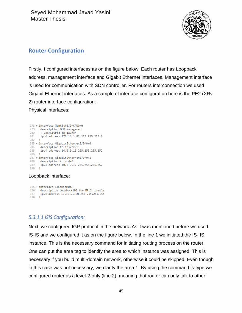
Router Configuration
Firstly, I configured interfaces as on the figure below. Each router has Loopback
address, management interface and Gigabit Ethernet interfaces. Management interface
is used for communication with SDN controller. For routers interconnection we used
Gigabit Ethernet interfaces. As a sample of interface configuration here is the PE2 (XRv
2) router interface configuration:
Physical interfaces:
Loopback interface:
5.3.1.1 ISIS Configuration:
Next, we configured IGP protocol in the network. As it was mentioned before we used
IS-IS and we configured it as on the figure below. In the line 1 we initiated the IS- IS
instance. This is the necessary command for initiating routing process on the router.
One can put the area tag to identify the area to which instance was assigned. This is
necessary if you build multi-domain network, otherwise it could be skipped. Even though
in this case was not necessary, we clarify the area 1. By using the command is-type we
configured router as a level-2-only (line 2), meaning that router can only talk to other

Seyed Mohammad Javad Yasini Master Thesis
46
level-2 routers. All the routers in the domain are configured as level 2 routers. The next
command net specifies the NET for the routing process. This is important to configure if
you are building up multi area domain. Line 4 copies the ISIS link-state information into
BGP-link state. This command is only inserted in the router which works as BGP
speaker talking to BGP Peer of OpenDayLight. In a nutshell, link-state information
gathered by IGP protocol in the domain (which in this project is ISIS protocol) will be
carried by BGP-LS protocol to the ODL BGP Peer. To keep other routers updated if a
neighbor router goes up or down, one should enable log-adjacency-changes (line 5).
Inside of address-family ipv4 unicast, firstly we configured metric-style wide, meaning
that IS can receive only new style TLVs. To enable a router to flood MPLS traffic
engineering link information through configured IS-IS level, one must configure it inside
IS-IS instance (lines 8-11). In our case, we configured distribution of MPLS links in
level-2-only and we specified Loopback address 100 as router ID. At the end, we
configured interfaces that are advertised by IS-IS. Firstly, we enabled Loopback
advertisement. This interface is in passive mode, meaning that we do not want packets
to be sent on that interface, we just want its announcement in the network. Here we also
specified Node-SID that will be bind to router's Loopback address. Other two interfaces
are configured as GigabitEthernet, point-to-point links and address family unicast.

Seyed Mohammad Javad Yasini Master Thesis
47
5.3.1.2 MPLS, PCEP and Segment routing configurations
After IS-IS, we configured MPLS. Firstly, we enabled two interfaces of PE2 which are
connected to PE1 and P5, for MPLS traffic engineering. Then we enter in PCE
configuration mode and there we specified peer IP address. In our network SDN
controller is PCE, so we defined its IP address as peer address (172.16.1.128). In case
of using the Cisco SDN controller, we were supposed to set IP address of the source
which is router’s management interface IP address.

Seyed Mohammad Javad Yasini Master Thesis
48
But in case of using ODL SDN Controller, by configuring source IP Address, we can
have the PCEP link UP, but we can never add LSP. Because The router loopback IP
used for BGP-LS must match the PCEP IP(here by this config PCEP IP would be
172.16.1.82). That's how the two topologies are tied together. So, while using ODL, the
configuration of PCE on router must be like following.
Note that for PCE-P to come up your ODL instance will need to be able to route back to
the loopback addresses in your XRv network. Those are e.g. in 10.10.0.0/16 then I went
to the ODL host and do something like:
sudo route add -net 10.10.0.0/16 gw 172.16.1.82
if we want this to persist after a reboot then edit /etc/network/interfaces (this is assuming
Ubuntu) and add:
up route add -net 10.10.0.0/16 gw 172.16.1.82
PCE must be configured on each router to enable path setup. Also, in OpenDaylight, in
PCE module, we will configure peering address. Here, it must be specified that we want
path computation in SR mode (lines 13-16). Firstly, stateful client. This means that
router will add stateful capabilities TLV when opening the new session. Moreover, we
can configure delegation of all active tunnels to PCE. In reality, this command allows
SDN controller to change existing LSPs while computing new paths. This is useful if
PCE wants to re-optimize traffic-engineered tunnels. Speaker ID is always router's
Loopback ID. To configure the range of tunnel IDs to be used for stateful PCE

Seyed Mohammad Javad Yasini Master Thesis
49
instantiation requests we used command auto-tunnel-pcc and we specified the min and
max tunnel ID. In line 23 re-optimization for the specified number of seconds is
configured, meaning that installation of new LSPs with new labels after tunnel re-
optimization will happen in specified number of seconds.
The presented configuration is valid for all the Edge routers in the network; one just
should change IP addresses and SIDs that are router-specific. Here in the
table one can find IP addresses and SIDs we used.
Router ID Loopback Address Management Interface Node SID
PE1 10.10.1.100 172.16.1.81 17001
PE2 10.10.2.100 172.16.1.82 17002
PE3 10.10.3.100 172.16.1.83 17003
PE4 10.10.4.100 172.16.1.84 17004

Seyed Mohammad Javad Yasini Master Thesis
50
In this network, we elected PE2 to be a BGP speaker and to redistribute all IGP
information to OpenDaylight.
Core routers (P5, P6, P7, P8) have simple configuration of interfaces and also ISIS. The
MPLS-TE should be enabled on core routers.
The BGP configuration is presented in the figure below. As in IS-IS, firstly BGP instance
should be opened. Again, we have area tag 1, which is the same as IS-IS tag. Then, we
specified the router Loopback address as a router ID. BGP neighbor is SDN controller
with is specified in line 10. SDN controller belongs to remote AS and that is configured
in line 11. Management interface is used to update SDN controller about link-state
information. In line 15 and 16 we enabled policy exchanging.
5.4 OpenDaylight Configuration
In ODL in BGP module which is placed ‘/etc/opendaylight/karaf’ in file 41-
bgp-example.xml should be reconfigured. In the line 5 we specified the
management interface of BGP speaker (PE2).

Seyed Mohammad Javad Yasini Master Thesis
51
5.5 MPLS-TE and SR-TE Tunnel Setup by OpenDayLight
5.5.1 MPLS-TE Tunnel Setup
For establishment of a new MPLS tunnel, we should send a REST command to PCEP
module inside ODL and ask for adding LSP. Inside postman application we should
define parameters for making connection to ODL and sending the right data model in
XML or JSON format. The sample PCEP tunnel creation is shown as below figure:

Seyed Mohammad Javad Yasini Master Thesis
52
First the action “POST” should be selected. This action should be send to the following
ODL module:
http://172.16.1.128:8181/ restconf / operations / network -topology-pcep: add-lsp
Connection Parameters should be defined as follow:
• Authorization: username and password of ODL which is admin/admin by default
• Header> content type: application/xml
• Header>accept: application/xml
Then we should fill out the body part of our message. For doing so, we should first
define which router is the ingress, which router is the egress, and the ERO (Explicit
route objects) meaning which nodes should be passed for this LSP. Following example
is for adding an LSP tunnel from node PE4 to node PE2, passing through explicit path
containing routers PE4>P8>P6>PE2.

Seyed Mohammad Javad Yasini Master Thesis
53
Line 2 defines the IP address of PCEP node which ODL will enforce relevant
configuration to. Line 6 delegate the control of this LSP to the PCE which is ODL, so
that this tunnel can not be deleted or modified by CLI on the router.
To check the tunnel to be created properly one should test it by inserting the command
“show mpls traffic-engineering tunnels brief”, as on figure below:

Seyed Mohammad Javad Yasini Master Thesis
54
As it is shown, “tunnel-te20” is created from PE4 to PE2 through Explicit route which we
defined in ERO. The character “>” before the name of the tunnel shows that creation of
this channel is made by somewhere outside the router which is enforced by ODL. The
reason for having “20” as tunnel ID is that we already configured by “auto tunnel PCC”
command to have tunnel numbers in the range of 20 to 99.
5.5.2 Segment routing-TE Tunnel Setup
For adding a new segment routing tunnel, similar to MPLS tunnel creation, we have to
use Postman with the same connection parameters, and we should send the
configuration to the same PCEP module of ODL. The different is that, for adding SR

Seyed Mohammad Javad Yasini Master Thesis
55
tunnels, we need to define the destination and the route of the tunnel by specifying the
SID numbers.
here I added one SR path from PE2 as source, to PE4 as destination, forcing the tunnel
to explicitly pass through PE1. Among core part of network in this scenario, when a core
router receives a packet, because it does not support segment routing, it routes the
packet based on shortest path algorithm to the corresponding IP address of next hop
defined for runnel. by sending this configuration to the opendaylight:

Seyed Mohammad Javad Yasini Master Thesis
56
In line 17, value should be set to “1” to specify this LSP as a SR-TE LSP. By the Line 21
and 29, the SR-ERO subobject represents IPv4 Node ID NAI. By line 23 and 30 we
define so that the SID value represents an MPLS label. Finally lines 24 and 31 is the
place we should put the value of SIDs, which we want out tunnel pass through them.
By inserting the command “show mpls traffic-engineering tunnels segment-routing” on
router, we can see the created tunnel:

Seyed Mohammad Javad Yasini Master Thesis
57
Line 6 shows the type of tunnel as a segment routing tunnel. Lines 33 and 34 show that
this tunnel is created by and delegated to the ODL, and finally lines 43 to 45 show the
segments which the tunnels is made from. In the core part of the network which routers
don’t support segment routing, they threat segment routing ID as MPLS labels and
forward the packet based on the shortest path algorithm to the destination. Here I

Seyed Mohammad Javad Yasini Master Thesis
58
created two other segment routing tunnels starting from PE2, which can be shown by
the command “show mpls traffic-eng tunnels segment-routing brief”:
As you can see, tunnel number 20 is destined to router PE1, and tunnel 21 is destined
to router PE4.
Chapter 6. Preparation of Input data for segment routing
Application in Network orchestrator
BGP-LS protocol gathers all topology-related information of the network from an IGP
routing protocol (ISIS or OSPF) in a network domain, delivering this information to SDN
controller. The SDN controller provide the possibility of configuration enforcement by
using PCEP protocol. As it was presented in previous chapter, for creation,
management and maintenance of segment routing tunnels in application layer, the main
information we need is corresponding Node SIDs of each router. In this work, I a going
to present two different ways for obtaining SID numbers; the first possible way is to get
SIDs numbers directly from the routers. The second way is to extract SID numbers from
BGP RIB in OpenDayLight.
6.1 Retrieving SIDs by NETCONF form routers
Netconf protocol is a subsystem of SSH protocol which is supported by XRv routers that
we used in this project. As the Netconf server we must install ncclient on ubuntu. I wrote

Seyed Mohammad Javad Yasini Master Thesis
59
a python code which code be considered as a part of network orchestrator for making
connection with routers, going through configuration of the router based on the specific
YANG data model (in our code ISIS YANG module), filtering the necessary information
(which here is the SID number), then storing retrieved information in a database
containing management interface of the routers and corresponding SID number (here I
used mongoDB). The python code is as following:

Seyed Mohammad Javad Yasini Master Thesis
60

Seyed Mohammad Javad Yasini Master Thesis
61
6.2 Retrieving SIDs from BGP RIB in OpenDayLight
The second alternative way for retrieving SIDs is a little trickier based on the fact that
we need to look at BGP RIB module of OpenDayLight and parsing and modifying data
to extract SID Values.
For doing so, we should send GET command to following address of ODL by Postman
application to receive all information stored in RIB:
http://172.16.1.128:8181/restconf/operational/bgp-rib:bgp-rib/rib/example-bgp-rib/loc-rib/
what we receive is a bunch of tables which what we should look for is in “linkstate-
address-family>bgp-linkstates”
In this table we can see all the link-states routes which are advertised to the ODL by
BGP-LS.

Seyed Mohammad Javad Yasini Master Thesis
62
Among all linkstate-routes, we have to look for the ones having value of “node-sid”
equal to “true” (line 27). Then as you can see in line 29, the index value of the SID can
be seen (in this case SID value of PE4) which for converting to absolute value and
storing in the database, it is enough to add 16000 to this value (result: 17004)
Seyed Mohammad Javad Yasini Master Thesis
63
7 Conclusion
This work was setup to investigate the source routing paradigm called Segment Routing
and comparing it to MPLS traffic engineering. Initially, we discussed Segment Routing:
general overview and its benefits in context of Software Defined Networking. The
implementation considered network creation in GNS3, setup of SDN controller and its
connection to the network, creation of MPLS-TE and Segment Routing tunnels inside
the network using SDN controller.
One of the main goals of this work was the usage of GNS3 network emulator as a free
platform with almost no drawback comparing to two other previous ways which were
commonly tried by other researchers.
In this work, I presented two different ways for obtaining SID numbers; the first possible
way is to get SIDs numbers directly from the routers. The second way is to extract SID
numbers from BGP RIB in OpenDayLight. These SIDs numbers can be used as the
main input of any application related to segment routing.
As a future works, one can make use of these SIDs for creation of a Graphical
application as a part of network orchestrator, for operation and maintenance of segment
routing tunnels.
Using GNS3 as a free-of-charge platform, and its feature for being executed on different
computers in the lab, while having possibility of networking those computers by a
hardware switch, gives the chance of creating a large network for evaluating different
scenarios as wide as real available networks worldwide.

Seyed Mohammad Javad Yasini Master Thesis
64
8 Acknowledgements
I would first like to thank my thesis advisor Prof. Maier Guido Alberto of the Department
of Electronic, Information and Bioengineering at Politecnico di Milano, for his guidance
and for giving me opportunity to realize this thesis work in Bonsai laboratory.
Furthermore, I would like to extend my thanks to Dr. Rodolfo Alvizu for sharing his
knowledge and providing helpful advices and support during this thesis work.
Finally, I must express my very profound gratitude to my parents for providing me with
unfailing support and continuous encouragement throughout my years of study. This
accomplishment would not have been possible without them.

Seyed Mohammad Javad Yasini Master Thesis
65
References
[1] Master Thesis of Miss. Ana Kos, Thesis named as: “Segment Routing Principles and
Applications for SDN, 2015”. “https://www.politesi.polimi.it/handle/10589/120653”
[2] Agarwal, Sankalp, Murali Kodialam, and T. V. Lakshman. "Traffic
engineering in software defined networks." INFOCOM, 2013 Proceedings
IEEE. IEEE, 2013.
[3] E. Rosen A. Viswanathan et al, Multiprotocol Label Switching Architecture,
IETF RFC 3031, January 2001
[4] C. Filsfils, S. Previdi et al. “Segment Routing Architecture”, IETF draft-ietfspring-
segment-routing-07, December 2015
[5] C. Filsfils, S. Previdi et al. “Segment Routing with MPLS data plane”,
IETF draft-ietf-spring-segment-routing-mpls-03, February 2016
[6] C. Filsfils, S. Previdi A. Bashandy et al. “Segment Routing Architecture”,
IETF draft-filsfils-rtgwg-segment-routing-00, June 2013
[7] C. Filsfils, S. Previdi et al. “Segment Routing interoperability with LDP”,
IETF draft-ietf-spring-segment-routing-ldp-interop-00, October 2015
[8] C. Filsfils, P. Francois, “Segment Routing Use Cases”, IETF draft-filsfilsrtgwg-
segment-routing-use-cases-02, October 2013
[9] P. Sarkar, H. Gredler et al. “Anycast Segments in MPLS based Segment
Routing”, IETF draft-psarkar-spring-mpls-anycast-segments-01, October 2015
[10] Pierre Francois, Clarence Filsfils et al.”Topology Independent Fast
Reroute using Segment Routing”, IETF draft-francois-rtgwg-segment-routingti-
lfa-00, August 2015
[11] Xiao, Xipeng, et al. "Traffic Engineering with MPLS in the Internet."
Network, IEEE 14.2 (2000): 28-33.
[12] Rosen, Eric, Arun Viswanathan, and Ross Callon. "Multiprotocol label
switching architecture." (2001).
[13] http://www.mplsvpn.info/2015/07/segment-routing-based-mpls-vsclassic.

Seyed Mohammad Javad Yasini Master Thesis
66
html
[14] http://blog.ipspace.net/2011/11/ldp-igp-synchronization-in-mpls.html
[15] Cisco,” MPLS Traffic Engineering (TE)--Fast Reroute (FRR) Link and
Node Protection”, retrieved from:
http://www.cisco.com/c/en/us/td/docs/ios/12_0s/feature/guide/gslnh29.html
[16] Filsfils, Clarence, et al. "Loop-free alternate (LFA) applicability in service
provider (SP) networks." Internet Engineering Task Force, RFC 6571 (2012).
[17] Hopps, Christian E. "Analysis of an equal-cost multi-path algorithm."
(2000).
[18] Manayya, K. B. "Constrained shortest path first." (2010).
[19] Hassine, Jameleddine; Hamou-Lhadj, Abdelwahab (September 29–30,
2014). "Toward a UCM-Based Approach for Recovering System Availability
Requirements from Execution Traces". In Amyot, Daniel; Pau Fonseca i Casas;
Mussbacher, Gunter. System Analysis and Modeling: Models and Reusability. 8th
International Conference, SAM 2014. 8769. Valencia, Spain: Springer. pp. 48–
63. ISBN 9783319117430.
[20] Fogarty, Susan. "GNS3 Network Simulator Raises Its Game". Network Computing.
UBM Tech. Retrieved 30 May 2015.
[21] Diego Kreutz, Fernando M. V. Ramos,Paulo Verissimo,Christian Esteve
Rothenberg,Siamak Azodolmolky and Steve Uhlig ,Software-Defined
Networking: A Comprehensive Survey, IEEE
[22] https://www.sdxcentral.com/resources/sdn/what-the-definition-ofsoftware-
defined-networking-sdn/
[23] http://blogs.cisco.com/sp/segment-routing-impact-on-software-definednetworks
[24] Cisco, Segment Routing for Service Providers,
http://www.cisco.com/c/m/en_us/training-events/eventswebinars/
webinars/segment-routing.html
[25] https://www.sdxcentral.com/resources/sdn/sdn-controllers/opendaylightcontroller/
[26] Khattak, Zuhran Khan, Muhammad Awais, and Adnan Iqbal.

Seyed Mohammad Javad Yasini Master Thesis
67
"Performance evaluation of OpenDaylight SDN controller." Parallel and
Distributed Systems (ICPADS), 2014 20th IEEE International Conference on.
IEEE, 2014
[27] http://thenewstack.io/sdn-series-part-vi-opendaylight/
[28] S. Previdi, C. Filsfils et al. SPRING Problem Statement and Requirements,
IETF draft-ietf-spring-problem-statement-07, March 2016
[29] https://github.com/CiscoDevNet/Opendaylight-BGP-Pathman-apps/
[30] https://github.com/CiscoDevNet/pathman-sr