implementing building information modeling within the...
TRANSCRIPT

Implementing Building Information
Modeling within the railway sector
Master of Science Thesis in the Master’s Programme Geo and Water Engineering
ANDRÉ NORBERG
Department of Civil and Environmental Engineering
Division of GeoEngineering
Road and Traffic Research Group
CHALMERS UNIVERSITY OF TECHNOLOGY
Göteborg, Sweden 2012
Master’s Thesis 2012:85


CHALMERS, Civil and Environmental Engineering, Master’s Thesis 2012:85 I
MASTER’S THESIS 2012:85
Implementing Building Information Modeling
Master of Science Thesis in the Master’s programme Geo and Water Engineering
ANDRÉ NORBERG
Department of Civil and Environmental Engineering
Division of GeoEngineering
Road and Traffic Research Group
CHALMERS UNIVERSITY OF TECHNOLOGY
Göteborg, Sweden 2012

CHALMERS, Civil and Environmental Engineering, Master’s Thesis 2012:85 II
Implementing Building Information Modeling within the railway sector
Master of Science Thesis in the Master’s programme Geo and Water Engineering
ANDRÉ NORBERG
© ANDRÉ NORBERG 2012
Examensarbete / Institutionen för bygg- och miljöteknik,
Chalmers tekniska högskola 2012:85
Department of Civil and Environmental Engineering
Division of GeoEngineering
Road and Traffic Research Group
Chalmers University of Technology
SE-412 96 Göteborg
Sweden
Telephone: + 46 (0)31-772 1000
Cover:
3D visualization of a part of Mälarbanan generated from Bentley Navigator.
Chalmers Reproservice
Göteborg, Sweden 2012

CHALMERS, Civil and Environmental Engineering, Master’s Thesis 2012:85 III
Implementing Building Information Modeling within the railway sector
Master of Science Thesis in the Master’s programme Geo and Water Engineering
ANDRÉ NORBERG Department of Civil and Environmental Engineering
Division of GeoEngineering
Road and Traffic Research Group
Chalmers University of Technology
ABSTRACT
The AEC industry has been struggling with low productivity development for a long
time. Building Information Modeling, BIM, is seen by many as the solution to this
problem. It origins from the manufacturing industry and has recently spread to the
civil construction sector where it is now used also in large infrastructure projects.
Project Mälarbanan will be the first project for Vectura to make use of BIM for
railway design at a high level. The purpose with this master thesis is to study how the
different parties in a large railway project look at the implementation and use of BIM.
It will describe the status of BIM within the railway sector at Vectura and identify
benefits and challenges from implementing it, and analyze how different
procurements affect the chances of succeeding with BIM. The information is collected
from both a literature review but also several interviews with key persons from
Vectura, the Swedish Transport Administration and NCC. The result shows that there
is no common picture of BIM in the industry; instead the parties tend to see only to
their part of the project. A deeper understanding of BIM in a lifecycle perspective is
lacking, and the knowledge varies greatly both between the companies as well as
within them. Object-based modeling and model-based collaboration are used in
project Mälarbanan, but the level of BIM integration seems to decrease from high in
the design phase, to lower in the production phase and when it comes to facility
management it is absent. There are many benefits related to visualization, better
understanding, design review, quality, productivity, re-use of information, time and
production planning, and an increased collaboration between the participants.
Challenges for the implementation of BIM include the legal status of the model,
vague owner demands, technology problems related to the new BIM tools and the
interoperability between them. A procurement which allows early collaboration
between the participants such as Integrated Project Delivery is the most suitable for
BIM projects, while more fragmented approaches like DBB cannot be recommended,
since BIM both demands and encourages an early, effective collaboration.
Key words: BIM, CIM, railway, design, infrastructure, procurement, facility
management

CHALMERS, Civil and Environmental Engineering, Master’s Thesis 2012:85 IV
Implementing Building Information Modeling within the railway sector
Examensarbete inom masterprogrammet Geo and Water Engineering
ANDRÉ NORBERG
Institutionen för bygg- och miljöteknik
Avdelningen för geologi och geoteknik
Forskargruppen Väg och Trafik
Chalmers tekniska högskola
SAMMANFATTNING
Byggnadsbranschen har kämpat med dålig produktivitetsutveckling under en längre
tid. Building Information Modeling, BIM, ses av många som lösningen på detta
problem. Det kommer från början från tillverkningsindustrin, men har på senare tid
spridit sig till anläggningsbranschen där det används för stora infrastrukturprojekt.
Projekt Mälarbanan är det första projektet för Vectura där BIM kommer att användas
på en hög nivå. Syftet med detta examensarbete är att studera hur de olika parterna i
ett stort järnvägsprojekt ser på införandet och användandet av BIM. Det kommer att
beskriva statusen av BIM på Vectura och identifiera villka fördelar som införandet
ger, samt de hinder som finns idag. Dessutom kommer chansen att lyckas med BIM i
samband med olika entreprenadformer att analyseras. Informationen är inhämtad dels
från en litteraturstudie, men också ett antal intervjuer med nyckelpersoner från
Vectura, Trafikverket samt NCC. Resultatet visar att det inte finns någon gemensam
bild av BIM i byggnadsbranschen idag; istället ser aktörerna till hur de kan nyttja det i
sin del av projekt. Vidare så är kunskapsskillnaden stor när det kommer till BIM, både
mellan de olika aktörerna men också inom dem, och det saknas en helthetssyn som
täcker hela livscykeln. I Mälarbanan används objektbaserad modellering och
samarbetet är modellbaserat, men nivån av BIM-integrering sjunker från hög i
projekteringsfasen, till låg i produktionsfasen och när det kommer till förvaltning så är
den obefintlig. Det finns många fördelar med BIM; visualisering, bättre förståelse,
samordning, kvalité, produktivitet, återanvändande av information, tid- och
produktionsplanering och ett djupare samarbete. De hinder som finns rör främst den
juridiska statusen på modellen, vaga krav från beställaren, tekniska problem rörande
BIM-verktygen samt interoperabiliteten mellan dem. En entreprenadform som medger
tidigt samarbete mellan projektdeltagarna som Integrated Project Delivery är mest
passande för ett BIM-projekt. Mer fragmenterade entreprenadformer som
generalentreprenad och totalentreprenad är inte fördelaktiga, eftersom BIM både
kräver och uppmuntrar ett tidigt, effektivt samarbete.
Nyckelord: BIM, CIM, järnväg, projektering, infrastruktur, entreprenadform,
förvaltning

CHALMERS, Civil and Environmental Engineering, Master’s Thesis 2012:85 V
Glossary
Bill of quantities - Mängdförteckning
Building Information Model - Byggnadsinformationsmodell
CAD Engineer - CAD-Projektör
Changes and additional work (CAW) - Ändrings- tilläggs- och avgående arbeten
(ÄTA)
Consideration of permissibility – Tillåtningsprövning
Counties Agency - Länsstyrelsen
Data coordinator - Datasamordnare
Design-build - Totalentreprenad
Design documents - Bygghandling
Design phase - Projektering
Design phase manager - Projekteringschef
Design review meeting - Samgranskningsmöte
Design-bid-build - Generalentreprenad
Deviation report - Avvikelserapport
Enquiry documentation - Förfrågningsunderlag
Environmental Code - Miljöbalken
Extended collaboration - Utökad Samverkan
Facility management - Förvaltning
Feasibility study - Väg- eller järnvägsutredning
Idea study - Idéskede
Initial study - Förstudie
Laydown area - Upplagsplats
Machine-guidance - Maskinstyrning
Owner - Beställare
Plan of mass disposition - Massdispositionsplan
Procurement - Upphandling
Quantitiy take-off - Mängdning
Railroad Construction Act - Lagen om byggande av järnväg
Railway investigation - Järnvägsutredning

CHALMERS, Civil and Environmental Engineering, Master’s Thesis 2012:85 VI
Railway plan - Järnvägsplan
Subcontractor - Underentreprenör
Surveyor’s assistant - Utsättare
Swedish Rail Administration - Banverket
Swedish Road Administration - Vägverket
Swedish Transport Administration - Trafikverket
Technical manager - Teknikchef
Tender - Anbud
Tenderer - Anbudsgivare
Dictionary
3D-model - Geometrical model in three dimensions; length, height and width.
4D-model - 3D-model plus time
5D-model - 4D-model plus cost
AEC - Architecture, Engineering and Construction
BIM – Building information modeling, the activity, when referring to a specific
building information model the term “BIM model” is used.
CAD – Computer Aided Design
DTM – Digital Terrain Model
EIA – Environmental Impact Assessment

CHALMERS, Civil and Environmental Engineering, Master’s Thesis 2012:85 VII
Contents
1 INTRODUCTION 1
1.1 Background 1
1.2 Definition of BIM 2
1.3 Purpose 2
1.4 Limitations 3
1.5 Methodology 3
1.6 Layout of the report 3
1.7 Literature 4
2 METHODOLOGY 5
2.1 Qualitative or quantitative research? 5
2.2 The relation between theory and empirics 5
2.2.1 Literature review 7 2.2.2 Survey- and interview techniques 7
2.3 The interview study 7 2.3.1 Choice of respondents 7 2.3.2 Formulation of questions 8
2.3.3 Performing the interview 9 2.3.4 Analysis of the information 9
2.4 The research process 9
2.5 Quality in qualitative studies 10
2.5.1 Reliability and validity 10
2.6 Method discussion 11
3 THEORY 12
3.1 The process of railway planning and construction 12
3.2 The Swedish Transport Administration 13 3.2.1 The different steps in a procurement 14
3.3 Different procurements and BIM 14 3.3.1 Design - Bid - Build 15
3.3.2 Design - Build 16 3.3.3 Integrated project delivery 16 3.3.4 Which building procurement is most suitable for BIM? 17
3.4 The concept of Building Information Modeling 18 3.4.1 Choice of BIM Definition 18 3.4.2 BIM in a wider context 19 3.4.3 BIM maturity 20 3.4.4 OpenBIM 21 3.4.5 Data exchange and interoperability 21 3.4.6 IFC – Industry Foundation Classes 22
CHALMERS, Civil and Environmental Engineering, Master’s Thesis 2012:85 VIII
3.5 BIM tools and parametric modeling 23
3.6 Mälarbanan – A BIM pilot project for Vectura 23 3.6.1 BIM Technology 24 3.6.2 The procurement in project Mälarbanan 26
3.7 Benefits from using BIM 29 3.7.1 Benefits for the owner 30 3.7.2 Benefits for the designer 30 3.7.3 Benefits for the contractor 31 3.7.4 Benefits for facility management 33
3.7.5 BIM for railway design at Vectura 34
3.8 Challenges for BIM implementation 35 3.8.1 The designer does not benefit most as the key adopter 35 3.8.2 Collaboration challenges 35
3.8.3 Legal status of the model 36 3.8.4 Changes in practice and use of information 36 3.8.5 Implementation issues 36
4 RESULTS AND EMPIRICS 38
4.1 The picture of BIM 38
4.1.1 Vectura 38 4.1.2 The Swedish Transport Administration 39
4.1.3 Contractor 40
4.2 From 2D to 3D: The status of BIM implementation 41 4.2.1 BIM maturity differences in the AEC industry 41
4.2.2 Education and BIM courses 42
4.2.3 Changes in the work method for CAD designers 43 4.2.4 BIM development projects 44
4.3 BIM in Mälarbanan 44
4.3.1 The ambition with BIM 44 4.3.2 3D object library 45
4.3.3 Common data sharepoint 45 4.3.4 Expectations of the new BIM tools 46 4.3.5 Facility management data 47
4.4 Owner demands of BIM 48
4.5 Benefits from using BIM 49
4.5.1 Owner 49 4.5.2 Designer 50
4.5.3 Contractor 52
4.6 Challenges 54 4.6.1 Technology related challenges 54 4.6.2 Interoperability challenges 54 4.6.3 Structural challenges 55
4.6.4 Juridical challenges 56
4.7 BIM depending on the procurement 57

CHALMERS, Civil and Environmental Engineering, Master’s Thesis 2012:85 IX
5 ANALYSIS AND DISCUSSION 59
5.1 Different views on BIM 59 5.1.1 From Vectura’s point of view 60
5.2 Implementing BIM within the railway sector 60
5.3 Status of BIM in the railway division 61
5.4 Benefits during design, construction and operation 63 5.4.1 Changes in the design curve 65 5.4.2 How can Vectura benefit from BIM? 65
5.5 Hinders and challenges 67
5.5.1 Legal status of the model 67 5.5.2 Technical challenges - interoperability 67 5.5.3 Different skill levels and vague owner demands 68
5.5.4 What happens after the construction phase? 69
5.6 BIM depending on the procurement 70 5.6.1 Mälarbanan – a step towards IPD 70
5.7 Suggested changes 71
6 CONCLUSIONS 73
6.1 Future research 75
7 REFERENCES 76
CHALMERS, Civil and Environmental Engineering, Master’s Thesis 2012:85 X
Preface
This master thesis is the final step in the Master’s Programme Geo and Water
Engineering at Chalmers University of Technology, comprising of 30 credits.
It is based on qualitative interviews with key persons from designer, owner and
contractor organizations within the AEC industry. The project is carried out at the
Department of Civil and Environmental Engineering, Chalmers University of
Technology, Sweden. It has been performed for Vectura in Stockholm with Jan
Dahlberg as supervisor and university lecturer Gunnar Lannér as examiner, both of
whom I would like to thank for their advice and encouragement throughout the
writing of this thesis.
The author would also like to thank all the informants from Vectura, the Swedish
Transport Administration and NCC. Without your contribution this master thesis
would not have been possible. A thank you is also extended to my opponent Martin
Rudolphi for valuable feedback on the report.
Stockholm, June 2012
André Norberg
CHALMERS, Civil and Environmental Engineering, Master’s Thesis 2012:85 I
1 INTRODUCTION
1.1 Background
For a long time the construction industry has been falling behind other industries in
terms of productivity. Statistics from SCB reveals that the Swedish manufacturing
industry productivity increases at a rate of 7,1 % every year during the period 1995-
2003. The productivity rate for the construction industry was for the same period -0,2
% (SCB, 2012). To address this problem the AEC industry today is undergoing a
change and is evolving away from 2D-CAD and paper towards 3D digital models
which contain more information and will help increase the productivity.
This new approach is known as Building Information Modeling (BIM) and is more
and more used in the industry (Steel et al, 2010). Intelligent, object-based 3D models
are central when using BIM and it can contain information about the construction
throughout its entire life cycle, from idea to design, construction and facility
management until demolition. BIM is used widely in the building sector with success
but has not had the same impact in the civil construction sector, in particular the
railway sector. Some aspects of BIM have been used but the full potential is yet to be
seen, but this is changing now as it is more common that the use of BIM is used in
larger infrastructure procurements. Consequently this means that the designers and
contractors need to implement BIM in the way they work if they want to stay in the
competition.
Vectura is an engineering consultant specializing in the fields of transport
infrastructure and movement planning. They develop and design sustainable transport
systems and offer services in the fields of investigation and analysis, design,
construction and project management, and operation and maintenance. Currently one
of their biggest projects, Mälarbanan, is being designed and this is a pilot project
where BIM is implemented in a large railway project. Mälarbanan between
Tomteboda and Kallhäll is one of the most congested parts of the Swedish railway
system; therefore a higher capacity is needed. Project Mälarbanan consists of
constructing two new rail tracks between Tomteboda and Kallhäll, north-west from
Stockholm C. Today this stretch consists of a double-track railway but it is getting
more and more clogged with the increasing number of inhabitants in the city of
Stockholm. Also, the new tracks would make it possible to increase the frequency of
departures, decrease the travelling time and improve the punctuality. The full distance
between Tomteboda and Kallhäll is 20 km but has been divided into two parts.
Vectura is currently designing the northern part, from Barkarby to Kallhäll, which is
about 8 km and is the first part to be built (Trafikverket, 2012).
For Vectura this is one of the largest and most challenging projects ever to be carried
out. Traffic on the railway will run throughout the whole time of construction except
for some shorter stops. This leads to large risks in the work environment and makes
the construction process more complicated. The process needs to be thoroughly
planned in order to succeed. The idea is that the use of BIM in combination with a
CHALMERS, Civil and Environmental Engineering, Master’s Thesis 2012:85 II
different type of procurement which enables early collaboration between Vectura, the
Swedish Transport Administration and the contractor at an early stage will make the
project more efficient.
Within railway design at Vectura, BIM has not yet been used much and there is not
yet a company policy for the implementation and use of BIM. Today 3D design is not
used within all the technical areas, for example within electric design which is more
schematic and here 2D is still used. Other areas such as track design have used 3D
modeling for a long time, and the goal is to create an information model where all the
technical areas can work collaboratively. The experiences from project Mälarbanan
will lead the future development within BIM at the railway division at Vectura.
1.2 Definition of BIM
There is no official definition of BIM in Sweden, thus the author needs to come up
with a definition to be used in this thesis.
The definition of BIM used for this report is adopted from GSA, the U.S. General
Services Administration:
“Building Information Modeling is the development and use of a multi-faceted
computer software data model to not only document a building design, but to simulate
the construction and operation of a new capital facility or a recapitalized
(modernized) facility. The resulting Building Information Model is a data-rich, object-
based, intelligent and parametric digital representation of the facility, from which
views appropriate to various users’ needs can be extracted and analyzed to generate
feedback and improvement of the facility design.”
The choice of definition will be further discussed in chapter 3, and BIM will be
explained in a wider context.
1.3 Purpose
The purpose of this master thesis is to study how the different parties in a large
railway infrastructure project look at the implementation and use of BIM. The report
will identify the benefits and challenges from implementing BIM in project
Mälarbanan and also look at the current status of the use of BIM in the railway
division of Vectura.
The thesis aims at answering and analyzing the following questions:
What is the view on BIM from the different parties in project Mälarbanan?
What is the status of BIM use in the railway sector at Vectura?

CHALMERS, Civil and Environmental Engineering, Master’s Thesis 2012:85 III
What are the benefits and challenges of implementing BIM in a large railway
project like Mälarbanan?
What type of procurement is most suitable for a BIM project?
1.4 Limitations
Since this study is performed by one student as a Master’s thesis and consists of 30 hp
(one semester’s full time work) both time and resources are limited. Therefore the
work is focused on BIM in project Mälarbanan and the parties involved in that
project.
The master thesis will investigate how Vectura can benefit from using BIM in project
Mälarbanan, and the report will focus on the use of BIM for designing railway.
Comparisons will however be made to the house building sector to point out the
differences.
Due to the limited time the number of interviews will be restricted, hence a selection
of the most important persons for the project will be made. The selection of
respondents will be further discussed in chapter 2.
With the use of BIM and digital information models instead of paper drawings certain
legal issues arise. In this report the focus is not on the legal issues that come with the
use of BIM, but they will be addressed briefly.
1.5 Methodology
In this study a number of different methods will be used to collect information and
data. General information about the background, theory about BIM and different
software applications is collected from relevant literature and digital sources. The
main part of the information will however be collected from interviews with key
persons involved at the different organizations, most of them directly involved in
project Mälarbanan. This includes persons from Vectura and the contractor as well as
construction managers. The methodology will be discussed further in detail in Chapter
2.
1.6 Layout of the report
Chapter 1 contains the introductory parts like the background, the working
definition of BIM, purpose, research questions, limitations and also previous
studies and a literature review.
Chapter 2 covers the methods used in this report for data collection which are
mainly a literature study and a number of interviews. The choice of
methodology is then discussed.

CHALMERS, Civil and Environmental Engineering, Master’s Thesis 2012:85 IV
Chapter 3 has all the necessary theory needed to comprehend the concept of
BIM and how the industry is evolving from paper-based design to intelligent
BIM models.
Chapter 4 contains the empirical results from the interviews. The answers
from the respondents are placed in a matrix, and presented in the text with
quotes from the respondents.
Chapter 5 holds the analysis and discussion of the result from chapter 4. The
theory provides a framework which is used together with the result from the
interviews along.
Chapter 6 contains the conclusions which are based on the research questions
in chapter 1.3.1, along with the theory, empirics and the authors own opinions.
1.7 Literature
There is an abundance of articles, scientific studies, and other literature sources
available about the subject, and it is difficult to cover it all, since the development
within BIM is rapid. Therefore it is important that the literature used is up to date. An
article written five or ten years back might not be completely accurate today.
Considering this, the aim has been to use as recent material as possible.
The BIM handbook (Eastman, et al. 2011) has provided much useful information
about BIM theory. It is a very extensive book about the BIM approach to design,
construction and facility management. The second edition of the BIM handbook is
from 2011 which means that the latest progress in technology is accounted for.

CHALMERS, Civil and Environmental Engineering, Master’s Thesis 2012:85 V
2 METHODOLOGY
In this chapter the methodology will be discussed, which includes different scientific
methods and techniques. Sometimes it can be hard to draw a clear line between the
two. The definition of method is a scientific way to approach the subject of the study
and how the subject is intended to be treated. Since the method affects how the study
is being performed it is important to choose a suitable method for the study. Examples
of different methods could be a simple description, make certain comparisons, form
hypothesizes or make predictions (Ejvegård, 2009).
The meaning of technique is how the information is being collected, for example from
interviews, surveys or experiments. The information is then used to describe,
compare, make hypothesizes or predict. The method can be seen as the wider and
more overall concept, while the technique is more mechanical and concrete (Ejvegård,
2009).
2.1 Qualitative or quantitative research?
Over the last decades many things have been written and a lot of discussions have
taken place about the concept of qualitative or quantitative research. The difference
between the two is how the collected information is generated, processed and
analyzed. A quantitative research method means that statistical methods are used for
the collecting and analysis of the information. A qualitative research method is more
focused on the “soft” data, i.e. qualitative interviews and interpretations. The two
different research methods often seem to exclude the other when practicing them, but
that is not the case. They can be considered to be on opposite ends on a scale, and the
main part of the research carried out today is somewhere between these two end
points. What determines the choice of one or the other is how the research problem is
formulated (Patel & Davidsson, 2003).
2.2 The relation between theory and empirics
The scientist’s work consists of producing theories that should give a realistic
knowledge of the reality. The foundation for the theory construction is data or
information about the part of the reality that is subject for the work. This material is
often referred to as “empirics”. It is then the work of the researcher to relate the theory
and empirics to each other. How to relate the theory to the empirics is a central
dilemma within all kinds of scientific work. There are different concepts that can be
used to relate theory and empirics; deduction, induction and abduction (Patel &
Davidsson, 2003):
Deduction means that a scientist works with known principles and theories
and, based on those, draws conclusions about certain subjects. Hypothesis
from commonly known theory are tested empirically in the research. An

CHALMERS, Civil and Environmental Engineering, Master’s Thesis 2012:85 VI
already existing theory determines what information is needed, how to
interpret the information and finally how to relate the results to the theory. The
objectivity in a deductive approach is assumed to be strengthened because the
base is taken from existing theory. This means that the research process will
be less colored by the individual scientist’s subjective opinions. However,
there is a danger that the theory used will affect the research in a way that for
example new observations are not taken into account (Patel & Davidsson,
2003).
A scientist who works inductive can be said to follow the path of discovery. It
means that the scientist can study the research object without using a
previously established theory. Based on the empirics (the collected
information) a theory is formulated. A risk with this approach is that the
scientist does not know the range of the theory or its generality since it is
based only on empirics that are typical for a certain situation, time or group of
people. The scientist must discover something that could be formed into a
more general theory, which means that the work is performed with open ends.
Also, the scientist has own ideas and conception which inevitably will color
the theories produced (Patel & Davidsson, 2003).
Abduction is the third way to relate theory and empirics and could be
described as a combination of the previously mentioned approaches.
Abduction means that based on a single case the scientist formulates a theory
that explains the case. This first step could be said to be inductive. In the next
step the scientist tries the theory or hypothesis on other cases, which is similar
to an inductive approach. The theory could then be developed and expanded to
become more general. An advantage with abduction is that the scientist is not
as locked as if working strictly deductive or inductive. The risk with abduction
is that all scientists are colored by previous experiences and research, which
means that no research is started impartially. The scientist could, without
knowing it, choose the subject of study based on previous experience, and
furthermore formulate a hypothesis that excludes other alternative takes (Patel
& Davidsson, 2003).
Within natural science the aim is to come up with a theoretic superstructure, a system
of empirically tested laws with full covering. Since this superstructure already exists
to a large extent within natural science and is considered to be verified it is the
deductive approach that is most common. Within other sciences it can be more of a
mix between deduction, induction and abduction (Patel & Davidsson, 2003).
The methodology used in this thesis is towards the inductive approach, the work starts
with a literature review and then interviews are performed to collect information,
which is then analyzed and discussed. According to Patel & Davidsson (2003) it is a

CHALMERS, Civil and Environmental Engineering, Master’s Thesis 2012:85 VII
qualitative form of research, where the respondents’ opinions about the subject have
been interpreted.
2.2.1 Literature review
The literature review usually consists of all the printed material available: books,
articles, reports, studies, essays etc. Information collected from the internet is also a
part of the material. When looking for information it is important to use relevant key
words to find the desired material. Another way of finding information is to follow a
chain of references. Scientists almost always list their references in their studies and
by following these new studies or books can be found (Ejvegård, 2009).
2.2.2 Survey- and interview techniques
To find out the opinion and knowledge from a population in a scientific context,
surveys and interviews are used. The survey is a written questionnaire which is
handed out to a number of people while the interview is consists of oral
communication between the researcher and the interviewee. Surveys and interviews
are used more and more frequently today for collecting information for essays and
studies. These techniques, especially the interview, can be used for almost any field,
since they all have their own experts. Sometimes the information from these experts
cannot be found in the literature available (Ejvegård, 2009).
2.3 The interview study
The interview study accounts for most of the information collected for this report. The
aim with the interview study was to investigate the view on BIM, collect experiences,
and get a picture of the BIM status in the industry today. The interviews provided
much valuable information about the advantages of using BIM, but also some of the
challenges that come with a new work method.
2.3.1 Choice of respondents
The respondents were chosen from the different organizations involved in project
Mälarbanan; Vectura, the Swedish Transport Administration and the contractor. From
the start the contractor was supposed to be procured in April, but this has been
delayed .Therefore another was chosen from a different railway project. By doing so,
it was possible to see if the picture of BIM varied among the parties, and to catch the
different opinions about BIM. The respondents were chosen from a contact list for the
project Mälarbanan, with additional help from people with insight in the project.
The respondents were chosen from different levels in the hierarchy, from design
engineers to specialists to project leaders. By doing so, a wider range of opinions and
ideas could be anticipated from the interviews. The level of knowledge about BIM
varied as well, from on one hand people who have practically never worked with
BIM, to BIM experts on the other hand.

CHALMERS, Civil and Environmental Engineering, Master’s Thesis 2012:85 VIII
Most of the respondents were naturally from Vectura’s organization since the study is
performed for them. It was also practical since they sit in the same office building.
Geographically the respondents range from Norrköping in the south up to Luleå in the
north. These interviews have been performed by using video conference software.
Most respondents however were located in the Stockholm area; see Table 1 below for
a complete listing of the respondents.
Table 1: Categorization of the respondents
Category Position
Designer Project manager
Designer Design coordinator
Designer Design coordinator
Designer Technical manager
Designer Model coordinator
Designer Senior CAD designer
Designer CAD designer signalling
Designer CAD designer track
Owner Design phase manager
Owner Data coordinator
Owner Technical manager
Contractor Project Engineer
2.3.2 Formulation of questions
The questions were formed based on the theoretic base provided by the literature
review, with respect to the respondent’s background and knowledge. The aim with the
questions was to give background information but also to answer the research
questions formulated in chapter 1.3. Many questions were the same for all
respondents, as for example their picture of BIM and the benefits and challenges of
implementing BIM.

CHALMERS, Civil and Environmental Engineering, Master’s Thesis 2012:85 IX
A number of questions were then specially formulated considering the background
and knowledge of the respondent. These questions varied and a BIM expert for
example got more in-depth questions compared to a project leader.
The interviews were semi-structured which meant that the questions were written
down beforehand, but during the interview follow-up questions could be asked when
needed. This makes it easier for the respondents to bring up things not included in the
questions. An effort was also made to keep the questions open so that the respondents
could answer without being directed by the formulation of the question.
2.3.3 Performing the interview
First, an e-mail was sent out to the respondents where a presentation of the Master
Thesis was made, and why their participation was important. Then a time and place
was decided and at least a couple of days before the interview, an e-mail was sent to
the respondents with the questions. By doing so the respondents could read through
the questions before, think about possible answers and be more prepared for the actual
interview.
Every interview was recorded and then typed in a text document. This was to make
sure that no information from the interview would be lost. The location of the
interview was mostly at the respondent’s work place. In some cases the interview has
been performed as a video conference due to long distances, where the respondent is
located in a different part of the country. However, personal interviews are preferred
since they admit a better contact with the respondent.
2.3.4 Analysis of the information
After collecting the information it is then sorted and made anonymous. A matrix
where the relevant information is placed is used to make a more systematic analysis.
The matrix is made with the purpose and research questions as a base. Finally the
result is presented in the text.
2.4 The research process
No matter how a research problem was born and what it contains, the research process
can be described in a number of steps in a logical order. The process starts with an
identification of the problem area, followed by a formulation of purpose and research
questions, a literature review, choice of technique for collecting information,
performing the work, processing, processing and finally reporting. However this is an
idealized picture of the research process. Very seldom can the steps be performed one
after the other in that very order. A reason for this is that the steps sometimes overlap
each other; another is that new knowledge and experience are obtained throughout the
research process which needs to be added. Sometimes it can even be positive to do
things in a different order. For example, when using a qualitative approach it can be
suitable to wait with the literature review until after the investigation (in this case the
interviews). A thorough theoretic work in the beginning of the process could hinder
the discovery of new knowledge (Patel & Davidsson, 2003).

CHALMERS, Civil and Environmental Engineering, Master’s Thesis 2012:85 X
The scientific approach will affect what we do during the research process, from
formulating the problem, going through the different steps to the reporting of the
result. But it does not matter if the research process has been performed step-by-step
or by jumping between the steps – the layout of the final report should look like the
idealized chain of steps mentioned above (Patel & Davidsson, 2003).
The process for performing this study can be seen in Figure 1 below.
Figure 1: The research process can be illustrated in the above steps.
2.5 Quality in qualitative studies
The quality in a qualitative study is depending on the whole research process. When
talking about the quality in a study there are two central concepts which will be
explained below; reliability and validity. These will be further explained below.
2.5.1 Reliability and validity
In a qualitative study the concept validity is the ambition to discover phenomenon and
describe opinions or a culture. In comparison, validity in a quantitative study is
depending that the right phenomenon is studied, with a solid theoretic base and good
instruments when performing the study (Patel & Davidsson, 2003).
Reliability in qualitative research is different from validity in quantitative research.
For example, if the same person is interviewed several times and the same question is
asked, but the answers differ, it is a sign of low reliability. In a qualitative study this is
necessarily not the case, and the reason for this is that the respondent might have
changed opinion, received new information or learned something since the last
interview. Within qualitative research the two concepts of reliability and validity are
so intertwined that scientists seldom use the concept of reliability. Instead the
meaning of validity is broader. Sometimes the term understanding or authenticity is
used instead (Patel & Davidsson, 2003).
As mentioned earlier the validity is not related only to the collection of data or
information; it includes all the parts in the research process. Considering the
Problem formulation
Literature review
Preparation for the
interviews
Interviews
Further literature
review
Additional interviews
Analysis
Discussion
Conclusion

CHALMERS, Civil and Environmental Engineering, Master’s Thesis 2012:85 XI
collection of information the validity is linked to the ability of the scientist to get
material for a credible interpretation. Furthermore the interpretation of the interviews
plays a central role for the validity. Thus, each qualitative research process is unique
and it is not possible to form any rules or procedures to ensure the validity (Patel &
Davidsson, 2003).
2.6 Method discussion
Several measures have been done to get a good and reliable result. If we look at the
collection of data first, the respondents have been given the questions in advance
which should increase the reliability.
Furthermore, the interviews were recorded which means that no information will be
missed from the actual interview and the transcript will be accurate. Otherwise there
could problems during the transcription process which affects the information. For
example, there is a difference between spoken language and written language.
It is also an advantage if the interviewer has good knowledge about the research
subject when performing the interview. The literature review that was done
beforehand provided the necessary knowledge.
However, time and resources are limited and it is very time-consuming to perform and
process interviews. It is possible that this affects the result, since the number of
interviews was restricted. With a larger number of interviews more opinions could
have been collected which might have led to a different result.
Due to circumstances out of my control the contractor in project Mälarbanan was not
contracted in time before the interviews were decided. Therefore a contractor from a
different infrastructure project was chosen as respondent. However, it was one of the
bigger players on the market, and also from a railway project, so that should not affect
the result.

CHALMERS, Civil and Environmental Engineering, Master’s Thesis 2012:85 XII
3 THEORY
In this chapter all the necessary theory will be given to comprehend the contents of
this report. The process of railway planning and production is described, as well as
the different procurements and the transformation in the industry from paper-based
design to BIM models.
3.1 The process of railway planning and construction
The railway process starts with an extensive planning process, which consists of the
first three phases; idea study, pre-study and railway investigation. As the process
moves forward the level of detail in the design increases. The first three phases mostly
consists of considerations between different public interests. Not until reaching the
work- and railway plan phase, is it possible to see for example how private land
owners are affected (Trafikverket, 2012a). The whole process can be seen in Figure 2
below.
Figure 2: The different steps in the railway process (Modified from Trafikverket, 2012)
The whole railway planning process is very heavy and time-consuming which means
that the time frame from idea to a finished railway is several years. The planning
process follows Swedish law under “Railroad Construction Act” and “Environmental
Code” (Trafikverket, 2012a). The different steps in Figure 2 are explained further
below:
Idea study - The railway process starts with several ideas and possible
solutions being analyzed and identified (Trafikverket, 2012a).
Initial study - The pre-study comprises alternate solutions and ideas and their
shortcomings and possibilities are documented. Some ideas are considered not
feasible, and are therefore sorted out. An important prerequisite is that an open
dialogue is kept with the society. The pre-study also includes a general
description of the environmental impact from the different alternatives
(Trafikverket, 2012a). Depending on the size, some projects need to be
approved by the government before moving on to the next phase. This means
that a new railway or a new track longer than 5 km or large reconstructions of
an existing railway generally have an important environmental impact and
need to be approved by the government (Trafikverket, 2012a).
Idea study Initial study Railway
investigation Work- and
railway plan Design
documents Construction
phase Facility
management

CHALMERS, Civil and Environmental Engineering, Master’s Thesis 2012:85 XIII
Railway investigation - During the railway investigation phase the remaining
alternatives are tested and analyzed. The purpose of this is to provide
information about the final selection of alternatives which are to be chosen
from. To this an EIA (Environmental Impact Assessment) is added which
should be approved by the Counties Agency. It is also investigated how the
alternative affects the existing road network, public transport, traffic safety
and availability and the environmental consequences (Trafikverket, 2012a).
Before moving on to the next phase the final alternative need the approval of
the government, which is done after a consideration of permissibility.
Work- and railway plan - In this phase the final design and placement is
decided. It also means that the level of detail is higher compared to previous
phases, so that it is clear which buildings and land are affected by the new
railway. After that it is up to the Counties Agency to approve the EIA
associated with the alternative. The focus lies on having a dialogue with land
owners, municipalities and other agencies. Once the plan is finally approved,
there is a period for appeal before the railway plan is finalized. After that the
construction can begin (Trafikverket, 2012a).
Design documents - This phase consists of creating the necessary design
documents for the construction of the railway. The design documents include
the final design with the technical specifications. Only smaller deviations from
the railway plan are allowed. If larger deviations or changes are made it could
be necessary to change the railway plan or make a new one (Trafikverket,
2012a).
Construction phase - The construction of the railway facility is mainly done
by contractors. The construction phase starts as soon as the work and railway
plan is validated. Usually during construction there will be some adjustments
or changes to the design documents. The reason for this is that the reality
sometimes differs from the model, when it comes to bedrock levels for
example. However, the changes that can be made have to be within the railway
plan (Trafikverket, 2012a).
Facility management - After the completion of the construction phase the
railway is handed over to facility management which takes care of the long-
term operation and maintenance of the railway.
3.2 The Swedish Transport Administration
The owner of project Mälarbanan is the Swedish Transport Administration
(sometimes the abbreviation STA will be used in the text). They are the agency
responsible for all modes of traffic whether it is on roads or railways, in flight or on

CHALMERS, Civil and Environmental Engineering, Master’s Thesis 2012:85 XIV
the sea. STA has the overall responsibility to build, maintain, and operate all national
roads and railways (Trafikverket, 2012a).
3.2.1 The different steps in a procurement
The Swedish Transport Administration is an authority which by law must endeavor to
procure goods, services and contracts in competition. Trafikverket are bound to follow
both the Public Procurement Act and the Act on Procurement in the Water, Energy,
Transport and Postal Services Sectors. These acts are based on directives from the
European Union (EU). A number of fundamental EU principles have to be observed
when carrying out public procurements. All suppliers have to be treated in a similar,
open and non-discriminatory way (Trafikverket, 2012b).
The procurement process starts with a need for a service or contract within
Trafikverket. The chain of process can be seen in Figure 3 below. The next step is the
production of enquiry documentation, which describes what is to be procured,
including what requirements are placed on the tenderer and the subject of the
procurement, and finally how the tenders will be evaluated (Trafikverket, 2012b).
Figure 3: The process of procurement (Trafikverket, 2012b)
The next step is to advertise the procurement in a publicly accessible database and on
Trafikverket’s webpage. The different suppliers send in their tenders in the right time,
and after that an analysis is done by STA in accordance with the evaluation criteria set
out in the enquiry documentation. Then all tenderers are notified of which supplier (or
suppliers) who have been awarded the contract. At earliest ten days after the award
notification the contract is signed. The contract is then continually followed up during
the term of the contract (Trafikverket, 2012b).
3.3 Different procurements and BIM
The chance of succeeding with BIM at a high level in a project is depending on the
type of contract method used. Some of the most common ones used are Design-Bid-
Build (DBB) which accounts for about 90 % of public buildings and 40 % of private
buildings in the United States. Another common contract method is Design-Build
(DB) while more collaborative methods like Integrated Project Delivery (IPD) are on

CHALMERS, Civil and Environmental Engineering, Master’s Thesis 2012:85 XV
the rise (Eastman, et al. 2011). These different contract methods will be discussed
further into detail below. The function of the different methods can be seen in Figure
4 below.
Figure 4: Schematic diagram of Design-Bid-Build and Design-Build processes (modified from
Eastman, et al. 2011)
3.3.1 Design - Bid - Build
As mentioned above this is the most common contract method as of today. DBB has
two major benefits; more competitive bidding to achieve lowest possible price for an
owner, and less political pressure to select a given contractor.
In the DBB method, the owner hires an architect or designer, who then produces a list
of the building requirements (a program) and design objectives. The final documents
must satisfy local building codes and fulfill the program. Employees or external
consultants can be hired by the architect to help with structural components or piping
for example. These designs recorded on drawings which in the end must contain
sufficient detail to facilitate construction bids. It is common that the architect chooses
to include less detail in the drawings or try to restrict his responsibility because of
potential liability. This often leads to disputes with the contractor when errors and
omissions are found which brings an extra cost to the project (Eastman, et al. 2011).
The next stage is for the owner to obtain bids from general contractors. Each general
contractor uses the quantities specified in the design documents to make a cost
estimate of the project. Possible subcontractors must go through the same process. It
is normal that one percent of the estimated cost for a contractor is related to compiling
bids. The winner of the procurement is usually the one with the lowest bid, including
work to be done by both general- and subcontractors. The winning contractor must
then redraw some of the original drawings and also produce their own shop drawings

CHALMERS, Civil and Environmental Engineering, Master’s Thesis 2012:85 XVI
which are more detailed. The shop drawings are used for actual fabrication, and if
these drawings contain errors it is likely that a time-consuming and costly conflict will
arise in the field.
Usually during the construction phase, many changes are made to the design as a
result of previously unknown errors, construction site conditions and changes in
materials available. Each of these changes requires a process in order to determine the
cause, who is responsible, and evaluate time and cost additions. This has to be solved
by the project team and the changes are likely to lead to legal disputes, added costs
and delays. Another problem associated with DBB is when a contractor bids below
the estimated cost in order to win the job. The contractor often abuses the change
process to recoup losses from the bid. Using DBB requires the procurement of all
material to be postponed until the owner approves the bid. This is one reason why the
DBB method is not the most time - and cost-efficient approach to design and
construction. The last phase is the commissioning of the building after the
construction is finished; final drawings are produced and delivered to the owner along
with all manuals for installed equipment (Eastman, et al. 2011).
3.3.2 Design - Build
In the DB process the owner contracts directly with the design-build team which is
normally a contractor with a design capability. This method makes the contractor
responsible for both design and construction as well as simplifies the owner’s
administration part. The DB contractor develops a building program and a schematic
design that meets the demands from the owner. Then the total cost and time needed to
design and construct the building are estimated. Once the potential modifications from
the owner have been implemented, the plan is approved and the final budget is
established. The big advantage compared to the DBB method is that the changes and
alterations in the design can be addressed earlier in the process, meaning both money
and time spent will be reduced (Eastman, et al. 2011).
The DB contractor hires specialty designers and subcontractors as needed, and after
this point the construction begins. Any changes to the design, errors and omissions
after this point are the responsibility of the DB contractor. Not all drawings need to be
in detail at the time of construction start. Due to this simplification, the building is
normally completed faster, cheaper and with fewer legal complications. A drawback
with the DB approach is that there is not much flexibility for the owner to make
changes once the initial design is approved and the contract amount is established
(Eastman, et al. 2011).
3.3.3 Integrated project delivery
The IPD approach is relatively new in the construction industry but it is getting more
and more popular. The reason for this is that it works well with BIM and the AEC
industry learns to use this technology to support integrated teams. There are multiple
approaches to IPD but the common factor is effective collaboration between the
owner, the prime (and possibly sub-) designer(s) and the prime (and possibly key sub-

CHALMERS, Civil and Environmental Engineering, Master’s Thesis 2012:85 XVII
) contractor(s). Already at an early stage the collaboration starts, and then continues
throughout the length of the project (Eastman, et al. 2011).
The key concept is that the different players work together using the best tools for
collaboration so that the project will meet owner requirements at a reduced time and
cost. The trade-offs that are part of the design process are best evaluated using BIM,
such as cost, functionality, aesthetics and constructability. In other words, BIM and
IPD go hand in hand and represent a very different approach to the previous linear
paper-based exchange of information. The owner benefits the most from using IPD,
but they must know what they want from the participants and how it will be achieved
(Eastman, et al. 2011).
3.3.4 Which building procurement is most suitable for BIM?
Of the above mentioned procurements the least suitable approach is the DBB one
since it is the most fragmented process and the contractor is not included in the design
process. This means that the contractor has to make a new building model after the
design is completed. However, since there are many alterations of the design-to-
construction business process and also of the project team, how the team members are
paid and who absorbs the risks. When it comes to the use of BIM one thing is clear
though – the positive effects from using this new technology is depending on both
how well the different parties collaborate and at what stage of the project they start
doing so. The DB approach could provide a good platform for BIM, since one single
entity is responsible for both design and construction. Of the three approaches
mentioned above the most suitable for BIM is the IPD approach, since it involves a
high level of collaboration (Eastman, et al. 2011).

CHALMERS, Civil and Environmental Engineering, Master’s Thesis 2012:85 XVIII
3.4 The concept of Building Information Modeling
3.4.1 Choice of BIM Definition
It is very popular to talk about Building Information Modeling in the AEC industry
today. People in the industry are generally positive and excited about the new
technology, but what do the three letters stand for? Some believe BIM is just a 3D
representation of a building or a facility, but there is much more to the concept. BIM
can sometimes refer to Building Information Management, which is linked to
Building Information Modeling. The discussions about BIM tend to be related to the
practical use of 3D-models for various purposes.
But as BIM is spreading to other areas within the AEC industry, the B in BIM is
somewhat misleading. Today BIM is used for design and planning of heavy civil
constructions such as highways and railways, and this application is being called CIM
sometimes, Civil Information Modeling (Palmer & Presley, 2009).
In Sweden there is not yet an official definition of BIM, therefore the attention was
turned outside the country borders where the development has gone further. During
the initial literature review a few different definition of BIM was discovered. For
example, National Building Institute of Building Sciences (NIBS) defines BIM as
follows:
“A Building Information Model, or BIM, utilizes cutting edge digital technology to
establish a computable representation of all the physical and functional
characteristics of a facility and its related project/life-cycle information, and is
intended to be a repository of information for the facility owner/operator to use and
maintain throughout the life-cycle of a facility”.
Jongeling, R (2008) uses the following definition of BIM in his report “BIM istället
för 2D-CAD i byggprojekt”:
“BIM is all the information generated and administrated during the lifecycle of a
building, structured and represented by using (3D) objects, where objects can be
building parts, but also more abstract parts such as voids. BIM-modeling is the
process to generate and administrate this information. BIM-tools are the IT-tools
used to create and handle the information. BIM is therefore not a technique, but a
common generic term for how the information is created, stored and used in a
systematic and quality-assured way”.
The definition of BIM provided by the large owner organization GSA can be seen
below (GSA, 2007):
“Building Information Modeling is the development and use of a multi-faceted
computer software data model to not only document a building design, but to simulate
the construction and operation of a new capital facility or a recapitalized
(modernized) facility. The resulting Building Information Model is a data-rich, object-
based, intelligent and parametric digital representation of the facility, from which

CHALMERS, Civil and Environmental Engineering, Master’s Thesis 2012:85 XIX
views appropriate to various users’ needs can be extracted and analyzed to generate
feedback and improvement of the facility design”.
The definitions are very similar with only smaller differences among them. BIM is the
process of creating an information-rich model by using advanced tools, throughout the
lifecycle of a building. Since there is very little that distinguishes one definition from
the other, the choice between them is of minor importance. The choice of definition
for this Master Thesis is adopted from the U.S. General Services Administration
(GSA), which provides and maintains workplaces for over a million employees in
8500 owned or leased buildings (GSA, 2007).
3.4.2 BIM in a wider context
So BIM describes the process of creating an intelligent data model which is used
during the whole life-cycle of a structure. That is the central part in the definition, but
BIM extends beyond the information model and demands new processes for how a
construction is being built. Moreover, BIM can also be divided into different fields
which can be seen in Figure 5 below, (Succar, 2009):
Figure 5: Describes the different fields of BIM in a Venn-diagram (Succar, 2009)

CHALMERS, Civil and Environmental Engineering, Master’s Thesis 2012:85 XX
The BIM Technology Field: Here is a group of players specialized in the
development of software, hardware and equipment to increase the productivity
and profitability in the AEC sectors. For example companies that develops
software solutions applicable to the design, construction and operation of
facilities.
The BIM Process Field: This field clusters a group of players who procure,
design, construct, manufacture, maintain and use the structures, for example
owners, architects, engineers, contractors and facility managers; organizations
involved in the ownership, delivery and operations of buildings or structures.
The BIM Policy Field: Holds a group of players with decision-making
capabilities, who focuses on preparing practitioners, delivering research,
allocating risks and minimizing conflicts within the AEC industry. For
example regulatory bodies, educational institutions and research centers.
3.4.3 BIM maturity
The concept of BIM maturity includes the BIM fields mentioned in Chapter 3.3.1;
technology, process and policy. Other important factors to measure BIM maturity
against are the data flows and the project lifecycle phases. Data flows are varied and
can be structured or non-structured, compare a database to an image for example. The
project lifecycle phases consist of design, construction and operations. BIM
implementation will change the components of and relations between these lifecycle
phases. The three BIM stages can be seen in Figure 6 below (Succar, 2009):
Figure 6: The different stages of BIM maturity (modified from Succar, 2009).
During the pre-BIM stage there is very much dependent on 2D documentation, even
though some 3D documentation is generated is lacks intelligence and cost-estimates
and quantities cannot be generated from the visualization model.
BIM stage 1 is initiated by the use of an object-based 3D parametric software tool
such as Revit, where users generate models within design, construction or operation –
the lifecycle phases. Collaborative practices are similar to pre-BIM status and there is
no significant model-based collaboration. However, the object-based models allows
for an earlier increased detail level of design and construction matters which enables
faster project life-cycle phases (Succar, 2009).
Pre-BIM BIM Stage 1
Object-based modeling
BIM Stage 2 Model-based collaboration
BIM Stage 3 Network-
based integration

CHALMERS, Civil and Environmental Engineering, Master’s Thesis 2012:85 XXI
BIM stage 2 is when players actively collaborate with players from other disciplines,
which may occur in many ways depending on the set of BIM tools used. Model-based
collaboration may occur within one or between two project lifecycle phases.
Contractual changes might be needed as model-based interchanges increases.
BIM stage 3 is when integrated models are created, shared and maintained
collaboratively throughout the project lifecycle phases. This can be achieved through
model server technologies using proprietary, open or non-open formats. At this stage
models become an nD model which means that complex analyses can be made at
early stages of virtual design and construction (Succar, 2009).
According to Bilal Succar the ultimate goal of BIM implementation is to reach
integrated project delivery (IPD), which integrates people, systems, business
structures and practices into a collaborative process to optimize project results,
increase owner value, reduce waste and maximize efficiency through all phases of
design, fabrication and construction (Succar, 2009).
3.4.4 OpenBIM
OpenBIM is a development program in the AEC industry, running from 2009 to 2011.
After the program was completed it was decided that OpenBIM should continue their
work without a time limit. The goal with the program is to accomplish a process
which guarantees participation and demands, with good architecture, good technical
solutions and the lifecycle economy in focus, and to achieve a more effective
construction and facility management so that, at latest, year 2013 can see a clear
impact of the costs for this (OpenBIM, 2012).
To achieve the goals of the program it is necessary that the stakeholders in the
program increase their participation and uses more alternative solutions which are
analyzed with the help of BIM models together with consequent use of BIM for
visualization, integration and automation of processes.
OpenBIM looks at real construction projects and facility management situations with
an emphasis on implementation. More than 60 companies are actively participating in
the OpenBIM project (OpenBIM, 2012).
3.4.5 Data exchange and interoperability
The idea of interoperability can be explained as a seamless exchange of information
between different computer programs. This has been a dream since the 1970´s and a
lot of effort has been put into this problem over the years. Even today we cannot be
sure that data transferred 100 % correctly from software A to software B. There are
many reasons for this and it is uncertain if we will ever reach 100 % interoperability.
But the use of object-based CAD systems in various areas of the construction industry
is improving the value of interoperability. It typically meets three different types of
technical needs (Drogemuller, 2009).

CHALMERS, Civil and Environmental Engineering, Master’s Thesis 2012:85 XXII
Interchange of information between different roles at a stage in a project. An
example of this is CAD data and quantity take-off software.
Continued use of information through the different stages of a project, from
initial and detailed design to construction, maintenance and finally
refurbishment or demolition.
To be able to access archived data throughout the life of a facility. For
example, information saved in the IGES format in the 1980’s and 1990’s is
still accessible even if the creating software is no longer available.
IGES (Initial Graphics Exchange Specification) was a data exchange standard in the
US. France used another one called SET (Standard D’Exchange et de Transfert) and
Germany had their standard called VDA-FS (Verband der Automobilindustrie-
Flächen-Schnittstelle). These competing data exchange standards led to problems
which caused ISO (International Standards Organization) to develop a set of standards
which were aimed for the manufacturing sector, known as STEP. But the
development process was slow and in 1994 Autodesk formed the Industry Alliance
for Interoperability which was developing Industry Foundation Classes (IFC). IFC
continued to build on the technology behind STEP but was customized to suit the
construction industry instead of the whole manufacturing sector (Drogemuller, 2009).
There are two major methods of exploiting BIM. The first one is to use a software
suite which supports the same data exchange standard. Often this means using
software from a single vendor, sometimes with add-on software from smaller
developers. Naturally, this model is strongly supported by the major CAD companies.
There negative side of this approach is that the range of software is restricted and the
data exchange is limited by the capabilities of the file format. The second approach is
to use software that supports an open exchange format, such as IFC (Drogemuller,
2009). It has the obvious advantage that any software can be used, as long as it
supports the exchange format. However, the downside is that the open standards do
not fully support the capabilities of the proprietary file formats.
3.4.6 IFC – Industry Foundation Classes
IFC is the main buildingSMART data model standard, and the IFC format is
registered by ISO and in the process of becoming an official international standard.
The IFC is a common data scheme for holding and exchanging data between different
proprietary software applications. The IFCs cover the many disciplines that contribute
to a building throughout its lifecycle from conception, through design, construction
and operation to refurbishment or demolition (BuildingSMART, 2012). Development
of the IFC was supported by Autodesk in the early years and then by the Finnish
government in the VERA program; a wide range of research and development

CHALMERS, Civil and Environmental Engineering, Master’s Thesis 2012:85 XXIII
projects to create a competitive advantage for the Finnish construction sector
(Drogemuller, 2009).
The fundamental idea with the IFC format is that it is open and not linked to a certain
software producer. It can be used to exchange and share BIM data between
applications from different software producers. As an open format it is neutral and
independent of a particular software producer’s development plans. The
implementation of an IFC exchange should follow specific requirements which
prevent uncertainty; it is important to be specific about what information is needed
(BuildingSMART, 2012).
The use of IFCs in the industry was low until 2006 when GSA in the US started to
demand the use of BIM models in their building design process. GSA controls the US
Government office and space requirements, responsible for over 8700 buildings. This
gave the IFCs a boost, and when the governments in Denmark and Singapore also
gave their support the software producers had no choice but to make sure their
software supported the IFC standards. Today the IAI is known as buildingSMART
and they continue to develop and promote the IFC model. Currently they are working
on a new IFC for infrastructure (BuildingSMART, 2012).
3.5 BIM tools and parametric modeling
What distinguishes modern BIM design applications from earlier CAD applications?
The difference is a technology called object-based parametric modeling, which was
developed in the 1980’s for manufacturing purposes. Instead of representing objects
with fixed geometry and properties, it does this by parameters and rules that
determine the geometry as well as non-geometric features. The parameters and rules
can be used to describe the relation to other objects, which means that objects
automatically updates according to changing contexts. This is called the behavior of
the object. Complex geometries can be modeled using this technique, which was not
possible with the old CAD applications. Companies can make customized object
libraries for a specific use, and add other attributes to the objects depending on their
need. BIM design tools allow the user to mix intelligent 3D modeled objects with 2D
sections for production of drawings (Eastman, et al. 2011).
Today’s BIM design applications can carry out specific tasks as a tool, while at the
same time providing a platform for data management within a model for different
uses. Some have the ability to manage data in different models, also known as a BIM
environment (Eastman, et al. 2011).
3.6 Mälarbanan – A BIM pilot project for Vectura
As mentioned in Chapter 1.1 Mälarbanan is a complex project consisting of extension
to four tracks, designing and constructing 8 km of new railway. In the project new
technology is used for BIM modeling purposes. Project Mälarbanan is a very

CHALMERS, Civil and Environmental Engineering, Master’s Thesis 2012:85 XXIV
important project for Vectura, since it is the first large railway project where BIM is
used, and some of the tools have been modified and customized to fit the use.
3.6.1 BIM Technology
Due to its history as Banverket Projektering, Vectura has inherited the same software
platform when it comes to design tools and software for railway projects. Bentley’s
suite of products is used for the design of the railway.
3.6.1.1 Microstation v8i
Microstation is a design software developed by Bentley and used globally as an
information modeling environment in the AEC industry. It can be used as a software
application for designs in 2D and 3D and to produce drawings and 3D PDFs.
Microstation can also be used as a technology platform for specific purposes with
applications from Bentley and other software vendors. There are specialized
applications for use within the civil field such as rail design and construction, track
maintenance and so forth. Moreover, Microstation can import and export DWG and
DGN formats among others. According to Bentley, it is used by 47 of the top 50 ENR
(Engineering News-Record) firms (Bentley, 2012a).
3.6.1.2 ProjectWise
Bentley ProjectWise is a project collaboration and information management software
developed for the AEC industry. The ProjectWise system consists of several
components; a schematic overview of it can be seen in Figure 10 below.
Figure 10: Shows the layout of the ProjectWise system with its components (Bentley, 2012b)

CHALMERS, Civil and Environmental Engineering, Master’s Thesis 2012:85 XXV
The system can be used for single offices or distributed services for a company or a
team project. Bentley ProjectWise Integration server is the central component of the
system, and often it is enough with just one integration server. Other servers are also
needed in the system; a caching server, a web server, a publishing server and a
geospatial server. However, the actual setup varies depending on the size and
complexity of the project. ProjectWise Explorer and Navigator run as desktop
applications for visual collaboration (Bentley 2012b).
3.6.1.3 RailTrack
RailTrack is a specialized application for preliminary and detailed 3D design of rail
infrastructure. It shares the same track geometry as PROL (Power Overhead Line) and
allows users to optimize horizontal and vertical track geometry to reduce project
costs. It can be configured to support a wide range of international standards and is
suitable for light rail, heavy rail, metros, high-speed rail and MAG-LEV projects
(Bentley, 2012c). Figure 11 below shows a railway model in 3D with views of the
cross section and profile.
Figure 11: Shows a view of Bentley RailTrack with Roadway Designer (Bentley, 2012c)
RailTrack offers a high degree of automation to established industry workflows,
which can be transformed into an increased productivity and time saving during the
design and maintenance of rail projects. Railtrack is used by infrastructure owners,
operating companies and contractors (Bentley, 2012c).
3.6.1.4 ProjectWise Navigator
Bentley Navigator is a standalone BIM design review tool with a 4D capability, which
means a project time plan can be attached to the model. It is used by infrastructure
teams to review and analyze project information. Multiple 2D and 3D design files
from many sources (DWG, DGN etc.) as well as i-models can be imported to
Navigator (Bentley, 2012). I-model is an extensible XML format for publishing DGN

CHALMERS, Civil and Environmental Engineering, Master’s Thesis 2012:85 XXVI
and other Bentley data, although a plug-in is also available for generating i-model
data from other applications such as Revit (Eastman, et al. 2011). 2D and 3D PDFs
can be produced which can be used by a wider group of stakeholders without access
to Navigator. Other capabilities are reviewing of clashes, analyze schedule
simulations and measure distances with high precision. Moreover, Navigator can be
used to mark up designs. For instance if there are two objects overlapping each other a
mark-up can be created which is saved for later (Bentley, 2012b).
3.6.1.5 PROL and Promis-e
PROL is Bentley’s application for designing the overhead line and catenaries and uses
the same track geometry as RailTrack. PROL can be used to generate realistic 3D
models for analysis and visualization, but also accurate project drawings and
deliverables for client approval and construction (Bentley, 2012d)
Promis-e is an application for control system design, solving tasks that involve
electrical schematics, connection lists, panel layouts and bills of material. Promis-e
integrates all these functions for a quick and efficient result. It includes a parts
database that allows users to associate components in the design with specific parts
information, and also enables easy generation of parts lists and other documentation
(Bentley, 2012e). An adaption of this application towards railway design will make it
possible to use it for electrical, signaling, and channelization purposes in
Mälarbanan1. A library of symbols needs to be designed before Promis-e can be used
in practice
3.6.2 The procurement in project Mälarbanan
This chapter is mainly based on the information from the project’s contract
documentation, provided by the Swedish Transport Administration.
The Mälarbanan project uses a relatively new contract method called “Extended
Collaboration”, which demands a specific commitment from the parties involved.
Collaboration at an early stage is encouraged, which differentiates it from other, more
traditional procurements like DBB and DB. The contract method is a step towards
IPD which was described in Chapter 3.1.3.It also means that the owner has double
roles in the project; first the normal, formal owner role as a counterpart in the project,
but also as a partner in the project collaboration (Trafikverket, 2011c). In Figure 12
below a schematic picture can be seen of the overall project organization.
1 Designer (Interview, 2012)

CHALMERS, Civil and Environmental Engineering, Master’s Thesis 2012:85 XXVII
Figure 12: The project organization in Mälarbanan can be illustrated by a Venn-diagram.
The circles that represent the different parties in the project have areas of their own,
and areas that are shared with one or both of the other parties. This is how the
collaboration works in practice; some parts of the work are carried out in teams with
one or more of the other parties, and some work is carried out separately. The idea is
that the collaboration will start at an early stage in the project to get the most from it.
The aim with the procurement in Mälarbanan is that all parties involved will benefit
from the increased collaboration (Trafikverket, 2011c).
It is clearly stated in the contract that a paper document is valued above a digital
document, which could cause legal issues later on in the project (see Figure 13
below). This will be discussed more in the analysis in Chapter 5.
Trafikverket
Contractor Vectura
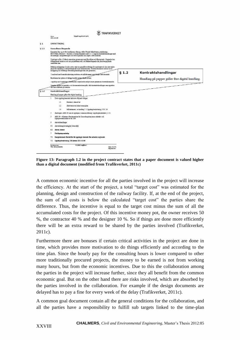
CHALMERS, Civil and Environmental Engineering, Master’s Thesis 2012:85 XXVIII
Figure 13: Paragraph 1.2 in the project contract states that a paper document is valued higher
than a digital document (modified from Trafikverket, 2011c)
A common economic incentive for all the parties involved in the project will increase
the efficiency. At the start of the project, a total “target cost” was estimated for the
planning, design and construction of the railway facility. If, at the end of the project,
the sum of all costs is below the calculated “target cost” the parties share the
difference. Thus, the incentive is equal to the target cost minus the sum of all the
accumulated costs for the project. Of this incentive money pot, the owner receives 50
%, the contractor 40 % and the designer 10 %. So if things are done more efficiently
there will be an extra reward to be shared by the parties involved (Trafikverket,
2011c).
Furthermore there are bonuses if certain critical activities in the project are done in
time, which provides more motivation to do things efficiently and according to the
time plan. Since the hourly pay for the consulting hours is lower compared to other
more traditionally procured projects, the money to be earned is not from working
many hours, but from the economic incentives. Due to this the collaboration among
the parties in the project will increase further, since they all benefit from the common
economic goal. But on the other hand there are risks involved, which are absorbed by
the parties involved in the collaboration. For example if the design documents are
delayed has to pay a fine for every week of the delay (Trafikverket, 2011c).
A common goal document contain all the general conditions for the collaboration, and
all the parties have a responsibility to fulfill sub targets linked to the time-plan

CHALMERS, Civil and Environmental Engineering, Master’s Thesis 2012:85 XXIX
concerning quality, environment and economy. According to the project contract the
final design documentation should be delivered at latest in the end of year 2016
(Trafikverket, 2011c).
3.7 Benefits from using BIM
Even though the AEC sector is in the early days of BIM use, there have been
significant improvements compared to the old 2D CAD or paper-based practices. The
advantages that will be presented in this chapter are not all in use as of today, but
within a near future they can be expected to happen as the BIM technology matures.
BIM is also working well alongside Lean thinking, which is to maximize the value
and minimize the waste, to drive the productivity further. Figure 7 shows BIM in the
center of building design and construction processes, as it meets the demands of an
increased pressure on the building process (Eastman, et al. 2011).
Figure 7: Increased pressure on the building process is resolved by
using BIM technology (East man et al, 2011)
This leads to a reduced time and cost for design and construction, an increased
complexity of design, a more suitable design and construction and an overall
improved building performance It also works well in combination with Lean
Production principles, aiming at eliminating all the factors in a production process that
do not add value to the customer in the end (Eastman et al, 2011).
Below is a list of the benefits from implementing BIM throughout the lifecycle of a
building or facility, from idea to design, from construction to facility management.
Some of the listed capabilities require more development and BIM maturity but most
can be realized today. They are based on chapters 4, 5 and 6 in the BIM Handbook
(Eastman et al, 2011).

CHALMERS, Civil and Environmental Engineering, Master’s Thesis 2012:85 XXX
3.7.1 Benefits for the owner
Concept, feasibility and design benefits
At an early stage, before the owner contracts an architect or designer, it is necessary to
know if a structure of a given size, quality and program requirements can be built
within a given cost and time budget. If these questions can be answered with a
certainty, the owner can know for sure that their goals are achievable. Finding out that
a certain design is over budget after a lot of time and effort has been put in is wasteful.
A BIM model linked to a cost database can be of great value in this situation.
Increased building performance and quality
Using a schematic model before a more detailed building model allows for a more
careful evaluation to determine whether the building meets the demands regarding
functional and sustainable requirements.
Improved collaboration using integrated project delivery (IPD)
BIM can be used at an early stage if the owner uses IPD for project procurement. This
means that design and cost issues are better understood, but also that the traditional
paper exchange and associated delays is avoided.
3.7.2 Benefits for the designer
Earlier and more accurate visualizations of a design
With the 3D model being designed directly, instead of being generated from multiple
2D views, it can be used to visualize the design at any part of the process.
Automatic low-level corrections when changes are made to the design
If using parametric modeling the objects are controlled by rules that ensure proper
alignment, then the 3D model will be free of geometry, alignment and spatial
coordination errors. Thus, the user’s need to correct design changes is significantly
reduced.
Generation of Accurate and consistent 2D drawings at any stage of the design
Since there is still a need for 2D drawings, these can easily be extracted from the BIM
model for a given purpose. This reduces the amount of time and number of errors that
are otherwise associated with the generation of construction drawings. If changes are
made to the design, new accurate drawings can be generated as soon as the design
modifications are entered.
Earlier collaboration of multiple design principles
Using BIM technology means that several teams can work simultaneously in different
design disciplines. This reduces the design time but also the number of errors and

CHALMERS, Civil and Environmental Engineering, Master’s Thesis 2012:85 XXXI
omissions. Furthermore it gives an earlier insight to where problems might be present
in a design, and also better possibilities to improve the design. It is more cost-efficient
to change the design at an early stage compared to waiting until the design is almost
complete, when the major design decisions have been made.
Cost estimates throughout the design phase
It is easy to generate a bill of quantities during any stage of the design phase, which
means that accurate cost estimations can be made. Further into the design process
there will be more detail in the quantities and more accurate cost estimation. In the
end of the design phase an estimate can be based on all the objects contained in the
model, which allows for a more accurate final cost estimate. It is clearly an advantage
to have the contractor in the project team when using BIM for cost estimation, their
knowledge is needed in terms of constructability insights and for more accurate cost
estimation.
3.7.3 Benefits for the contractor
Quick reaction to design changes
When changing an object in the model, the impact can be seen and changes to the
other objects will automatically update. Therefore it is easier to see the consequences
of a change in the model, and clashes are avoided this way. Furthermore design
changes can be resolved faster in a BIM system since modifications can be shared,
visualized, estimated and resolved without the use of paper drawings which is much
more time-consuming.
Discovery of design errors and CAWs before construction
If the 3D building model is the source where all the 2D and 3D drawings are extracted
from, design errors caused by inconsistent 2D drawings is not an issue any longer.
Also models from different disciplines can be brought together and compared
systematically. CAWs (Changes and Additional Work) are identified already in the
design phase rather than in the field during construction. The coordination between
designers and contractors in a project becomes better, and this also speeds up the
construction process and provides a smoother process overall.
Synchronization of design and construction planning
If a construction time plan is linked to the 3D objects, it is possible to simulate the
construction process and see what the structure looks like at any given point in time. It
will give an insight into how the structure will be constructed day-by-day, something
that is not possible from paper documents. The benefit is higher if also temporary
construction equipment is included such as scaffolding, cranes and other important
objects, so that these also can be added to the schedule activities.

CHALMERS, Civil and Environmental Engineering, Master’s Thesis 2012:85 XXXII
Better implementation of lean construction techniques
Using an accurate BIM model will provide an accurate estimation of the material
needed for each segment of the work, and enhances the planning and scheduling of
sub-contractors so that material, people and equipment will arrive just-in-time. This
minimizes wasted efforts and the need to stock material on-site, according to Lean
construction principles. It reduces the cost and helps improve the collaboration at the
jobsite. A mobile device with the model loaded into it can also be used for material
tracking, construction progress and automated positioning in the field.
Synchronization of procurement with design and construction
As mentioned before the BIM model can provide accurate quantities for all material
and objects in the design. This can be useful when it comes to the procuring of
material from suppliers and subcontractors. However, for this to work the object
definitions for many manufactured products have not been developed. When this does
happen, it will be possible to order exact quantities from the supplier, for example
pre-cast concrete elements and mechanical components.
Machine-guidance
By using machine-guidance the excavation of masses is made easier, quicker and with
a higher precision. The excavator is equipped with a computer which uses digital
terrain models (DTMs) which can either be transmitted by wireless or simply by a
USB memory stick. The excavator uses a GPS positioning system with one or two
antennas for orientation. Also the buckets are equipped with sensors that register
location as well as the angle of it so that the operator know both the rotation and
position of both machine and bucket (Infomap, 2012). Figure 8 below shows the
computer inside the machine which is operated by a touch-screen. It can hold multiple
DTMs for different purposes so that the machine can work efficiently without
unnecessary interruptions.

CHALMERS, Civil and Environmental Engineering, Master’s Thesis 2012:85 XXXIII
Figure 8: Shows the computer used by the operator, where the DTMs are controlled.
After calibration of the bucket, the accuracy is about 10 mm horizontally and 15 mm
vertically. The small device to the left in Figure 8 indicates when the bucket is in the
right location, and gives a warning if the operator excavates too deep for example.
Another benefit from machine-guidance is that the need of personnel decreases
(Infomap, 2012). Previously surveyor’s assistants put out pegs which the operator
used as indicators, now it is possible to work straight from the DTM in the computer.
The advantage with BIM is that the necessary DTM is ready to use without
modification when it is delivered from the designer. That saves the time it takes for
the contractor to develop their own model for machine-guidance.
3.7.4 Benefits for facility management
Improved commissioning and handover of facility information
The contractor and possibly sub-contractors collects information about materials used
and maintenance information for the different systems. If this information is linked to
the respective objects in the BIM model then the model itself can be used for facility
management. It can also be used before the handover to check that all the systems are
working as designed.
Better management and operation of facilities
The BIM model is a source of information for all the technical systems used in a
facility. Analyses done earlier for example regarding control systems and mechanical
equipment can be provided to the owner to verify the chosen design once the building

CHALMERS, Civil and Environmental Engineering, Master’s Thesis 2012:85 XXXIV
is in operation. The information can be used to monitor the systems when the building
is in use and make sure they work properly.
Integration with facility operation and management systems
The building management can benefit from an updated building model as a starting
point, since it can provide useful as-built information about spaces and systems. It can
facilitate monitoring of control systems and supports remote operating management of
facilities. There are many possible areas where a BIM model can be useful when it
comes to facility management, but many of these capabilities have not yet been
developed.
3.7.5 BIM for railway design at Vectura
Vectura has had a project for the implementation of BIM in the railway division at
Vectura. This chapter is based on the resulting project report (Vectura, 2012).
Vectura has adapted a “BIM-ladder” with a step by step implementation of BIM, see
Figure 9 below. The first step represents the work method pre-BIM where the design
was done in 2D. The next step is a 3D model but with the data in a separate system,
this is not BIM either. Not until the 3D model contains intelligent object it can be
called BIM, and then the level of BIM is increasing with added time planning (4D)
and cost calculation (5D). The BIM model can also contain noise calculations, fire
analysis and energy simulations, in the future depending on how far the development
reaches.
Figure 9: The different stages in the “BIM-ladder” with an increasing level of BIM to the right.
2D plus data in separate system
3D in a common model plus data in separate system
3D and data in the model, objects and object information, quantitiy take-off
4D with time planning
5D with cost calculation

CHALMERS, Civil and Environmental Engineering, Master’s Thesis 2012:85 XXXV
Benefits for Vectura identified from the project:
A better understanding for the railway facility since all CAD designers can see
the common 3D model at an early stage in the project
Better review of object placement, everything is in a 3D environment. A
condition is that all technical areas work in the same model.
Design material in a digital environment can facilitate visualization,
simulation, quantity take-off, time planning, cost calculations etc.
Re-use of data through different stages in the process.
Better quality and timesaving through a more effective work method.
Fulfillment of new industry standards for upcoming procurements
3.8 Challenges for BIM implementation
It is easier said than done to embrace the use of a new technology which also requires
new processes and changes to be implemented for each part of the design and
construction phase. Inevitably this leads to challenges and problems that must be
identified and solved.
3.8.1 The designer does not benefit most as the key adopter
The benefits for the owner in a BIM project are easily seen, it allows for design
optimization, fewer construction errors and fewer design coordination issues. The
contractor also benefits from production planning and reduced fabrication costs.
However, for designers the economic benefits are less apparent. The designer has to
invest in new hardware and licenses for software and train the staff, and unless the
designer receives shares of the economic benefits this is a significant obstacle to the
implementation of BIM. Furthermore BIM can increase the potential liability of the
designer, but new business models are developing slowly to address this problem
(Ashcraft, 2009).
3.8.2 Collaboration challenges
BIM works as a platform for increased collaboration, which means that issues arise
regarding the development of effective project teams so that access to the model
information is achieved. For example, if the designer is using traditional paper-based
drawings, then it is necessary for the contractor to build a model that can be used for
construction planning, estimating and coordination. And if the model is created using
BIM, then the level of detail might be an issue if it is too low, or if it has inadequate
object definitions. This might also require a new model for the construction. Another
collaboration problem might occur if the members of the project use different

CHALMERS, Civil and Environmental Engineering, Master’s Thesis 2012:85 XXXVI
modeling tools. To move the model from one environment to another, or to combine
models might in this case require more tools for doing so, errors might occur while
doing so. IFC could be a solution to these problems (Eastman, et al. 2011).
3.8.3 Legal status of the model
Another problem is the legal status of the model. The current practice uses several
models to communicate the design and construction intent for a project. This means
that the complete design is not visualized until they are imported to a viewing
program. Usually the models do not contain all the necessary details for construction,
therefore additional 2D information is added to the model. Then there are the
permitting agencies that are not ready to view digital information and require
traditional submissions of printed drawings. Another question is regarding how to
stamp the model. Currently these issues are solved by using a printed submission as
the contract document, even though the work up until then has been digital. But what
is the legal status of the model if it is not a contract document? This question has a
few different answers, the first one is that the model is a “co-contract document” used
between the parties in the project, but not used for permissions by agencies. With this
view, the question of inconsistencies handling needs to be stated in the contract
(Ashcroft, 2009).
3.8.4 Changes in practice and use of information
By using BIM the integration of construction knowledge will start earlier in the design
process. This will benefit integrated design-build firms capable of coordinating all
phases of the design. Contract methods like IPD that require good collaboration will
provide better advantages to owners with the use of BIM. However, the most
significant change for firms that implement the use of BIM is the use of a common,
shared building model during the design, and a set of building models as a basis for
the construction (Eastman, et al. 2011).
3.8.5 Implementation issues
The change when going from a traditional 2D or 3D CAD environment to a building
model system involves much more than only acquiring software, upgrading hardware
and training the staff. An effective use of BIM requires that changes are made to
almost every aspect of a company’s business practice, and not just doing the same
things in a different way. A basic understanding of BIM with its related processes is
needed and a plan for the implementation. What the changes will be is depending on
the specific company and their activity in the AEC sector. However, there are some
general steps that need to be considered, which can be seen below (Eastman, et al.
2011).
Top-level management need to develop a BIM adoption plan which covers all
aspects of the company’s business and how the changes will affect both
internal departments and external partners and clients.

CHALMERS, Civil and Environmental Engineering, Master’s Thesis 2012:85 XXXVII
Create a team with key managers responsible for implementing the plan, with
cost, time and performance budgets to guide their performance.
Start using BIM in one or two smaller projects in parallel with existing
technology and produce traditional documents from the building model. This
will help reveal where there are missing building objects, deficits in output
capabilities and in links between programs. This way the company can also
develop modeling standards and determine the quality and detail level of
models.
The initial results can be used to educate and guide the continued BIM
adoption of software as well as staff training. Keep senior management
updated on the progress, insights etc.
Continue to integrate BIM capabilities into more aspects of the company’s
functions. Reflect the new business processes in contractual documents with
business partners and clients.
Look back and observe the implementation process, reflect on the benefits and
problems observed so far. Set new goals for performance, time and cost and
continue to extend BIM-facilitated changes to new locations and functions
within the company.

CHALMERS, Civil and Environmental Engineering, Master’s Thesis 2012:85 XXXVIII
4 RESULTS AND EMPIRICS
This chapter will present the result from the interviews. The information from the
interviews has been placed systematically in a matrix according to the question and
respondent.
4.1 The picture of BIM
The picture of BIM varied both within the different organizations but also among the
respondents from the same organization. Some have very limited knowledge about
BIM while others have been working with it for several years, and therefore has a
wider understanding of the concept.
4.1.1 Vectura
A CAD designer2 at Vectura pictures BIM as a tool to produce 3D designs, but also
for information. A quote from another CAD designer3 shows a more extended view
on BIM:
“Many people think that BIM is merely a 3D model, but it is more than that. It is a
whole process where you work in a digital information model with intelligent 3D-
objects with attributes, links to type sections, article numbers and more so that
quantity take-offs can be made by a single click on the button”
A senior CAD designer4 comments that BIM is not something widespread within the
infrastructural area of the industry. He thinks that BIM is something more related to
house building where it has been used frequently for a longer time. The use in the
infrastructural area has not yet reached there.
A model manager5 sees BIM as something useful starting from an early phase in a
project and all the way through planning and construction to facility management:
“There are benefits from using BIM, depending on the phase you are currently in, all
the way from the initial study to the management of the facility. My picture of BIM is
the process of getting as much information along from the first stroke of the pencil to
the finished product”
Another comprehension is that even though the word BIM is something rather new,
some of the activities associated with it are known and has been used for a long time,
for example modeling in 3D. This can be underlined by a quote from the project
manager6:
“The word BIM, Building Information Modeling, was something completely new to
me. BIM for me today means 3D, it is just a word. 3D plus the time axle is 4D and
2 Designer (Interview 2012)
3 Designer (Interview 2012)
4 Designer (Interview 2012)
5 Designer (Interview 2012)
6 Designer (Interview, 2012)

CHALMERS, Civil and Environmental Engineering, Master’s Thesis 2012:85 XXXIX
that is also a part of BIM, and then material lists can be added. Right now it is an
object in 3D that we can add attributes to”
If working and communicating with models in the railway sector is a new
phenomenon, consultants working with road resign have more experience in this field.
Vectura designs both roads and railroads and a design coordinator7 who used to work
with road design says that they have been working with models for 10 years.
However, it is not until later years that the model has been coordinated with respect to
all the technical areas. He is quoted8:
“Road design is ahead of railway design when it comes to the use of BIM. We have
had 3D-visualization for a long time”
This shows that there is not just a different BIM maturity and picture among the
different players on the market, but also differences between technical areas within
one organization. DTMs have been used for road design for a long time, and also
clash detection9.
A technical manager10
at Vectura has visited user conferences and exhibitions and
there BIM has been a popular topic the last couple of years. But the people visiting
these exhibitions tend to be on the frontline of the development. It is difficult to say if
there are only specific projects that are ahead in the use of BIM or if that is true for
the whole infrastructure sector11
.
4.1.2 The Swedish Transport Administration
The Swedish Transport Administration (STA) is the biggest owner of railway and
road projects in Sweden. At the moment the STA has several large pilot projects
within infrastructure that use BIM in order to develop new work methods. At the
moment they are unsure which way they should go, and that is what these projects
will determine in the future. Currently the projects have not reached the construction
phase and therefore it is too early to draw any conclusions from them.
It is clear that the level of BIM knowledge varies within the organization. One design
phase manager has not yet worked with a BIM project but he is very excited and
positive about this new approach to design12
. He sees benefits such as less paper
drawings in the future, and that collisions and colliding objects are detected earlier in
the design process.
A data coordinator13
suggests that BIM is used to make the work and planning process
more effective. In other words this means that the STA as the owner not only receives
drawings, but a more intelligent model file that can be used for many purposes, for
example machine-guidance.
7 Designer (Interview, 2012)
8 Designer (Interview, 2012)
9 Designer (Interview, 2012)
10 Designer (Interview, 2012)
11 Designer (Interview, 2012)
12 Owner (Interview, 2012)
13 Owner (Interview 2012)

CHALMERS, Civil and Environmental Engineering, Master’s Thesis 2012:85 XL
A technical manager argues that his opinion that the STA are slow to adapt and
embrace BIM14
. The STA sees a great development potential with BIM, but the driver
behind this is the market, and not themselves. He says15
:
“There are a couple of BIM pilot projects, but in my opinion we don’t have a strategy
for how we should proceed. Instead we are listening to the market. This is because we
want to take both designers and contractors into consideration”
The STA is currently looking to hire a BIM strategist, who can coordinate and guide
the organization in BIM-related decisions. At the moment the pilot projects are
pointing out different directions, each with specific technical solutions16
.
4.1.3 Contractor
NCC Construction Sweden builds everything from housing, schools and sports
facilities to roads, railways and power plants. They are organized in four regions:
Southern, Western, Stockholm - Mälardalen Region and Northern Sweden (NCC,
2012). They are currently building a new logistics center in Rosersberg outside
Stockholm. The project engineer17
for this project claims that they have been using
BIM in infrastructure projects for at least 15 years. He gives an example of when they
built runway 3 at Arlanda airport some years ago18
:
“It wasn’t called BIM at the time, but we had a digital 3D model over the airport, and
that is BIM. On the other hand, maybe we didn’t have all the drainage pipes in 3D but
the surface was in 3D, and you knew exactly the gradient of the runway as well as the
surface run-off areas and slopes. It is not something new”
NCC has had a BIM strategy for 4 years, but the use and level of BIM varies greatly
from project to project, and also depending on the region within the company. They
have state of the art projects where BIM has been used at a high level, with both 4D
and 5D for time planning and calculations, but also projects where BIM has not been
used at all. NCC’s BIM strategy is to use a high level of BIM in their “own” projects,
which means projects where they have control over the design phase. The project
engineer19
is quoted:
“We are not allowed to start such a project without BIM, where we can affect, or be
in charge of the design”
By using BIM in a project it sharpens the requirements for the CAD designer in the
design phase, that he produces a correct model without errors. Previously it was
enough if the designer made a 2D drawing where the depth in the Z-axis was not
included and type sections or normal sections was used. Now it has to be very exact
14
Owner (Interview 2012) 15
Owner (Interview 2012) 16
Owner (Interview, 2012) 17
Contractor (Interview, 2012) 18
Contractor (Interview, 2012) 19
Contractor (Interview, 2012)

CHALMERS, Civil and Environmental Engineering, Master’s Thesis 2012:85 XLI
according to the surroundings where the connections are between the model and the
existing objects.
4.2 From 2D to 3D: The status of BIM implementation
BIM originates from other industries such as manufacturing and industrial design,
where the need to control information from the design of a product all the way to
manufacturing was vital. Then the BIM concept spread to other industries such as the
AEC sector, and primarily within house building. Within heavy civil construction like
railways the use of BIM is not as widespread. According to a technical director the
prioritized focus areas of BIM should be production and facility management20
. One
of the biggest costs is the long-term maintenance of a railway facility. He is quoted21
:
“It is easy to focus on the investment cost and forget the cost for long-term
maintenance. By minimizing the need for maintenance the initial cost could be higher
but you would still benefit in a longer perspective”
If the cost for the design phase only is around 10 % of a project’s total budget it
means that adding more hours of planning in the design phase does not affect the
project budget all that much, and money could be saved in the production and facility
management phases.
4.2.1 BIM maturity differences in the AEC industry
BIM within house building is more developed since they started earlier and this has
several reasons. The B in BIM stands for Building, and the need to use BIM within
house building was identified earlier22
there. They realized the advantages from using
BIM such as clash detection which is more useful within complex buildings where
many subcontractors are involved as well.
A railway is flat, and very long-stretched. It is not built vertically like a tall building
so there is not the same need to express the design in 3D. This is another reason why
the need for 3D modeling was bigger within house building compared to railway
projects where 2D has dominated for long23
, and this has driven the BIM
implementation further within house building.
The railway sector is very traditional, in a way that makes it slow to react to and
embrace new technologies24
. This could be a reason for why BIM is not as widespread
within infrastructure according to several of the respondents. There is an “old way of
thinking” in the railway sector, which makes the process slow when adapting to a new
20
Designer (Interview, 2012) 21
Designer (Interview, 2012) 22
Designer (Interview, 2012) 23
Designer (Interview, 2012) 24
Designer (Interview, 2012)

CHALMERS, Civil and Environmental Engineering, Master’s Thesis 2012:85 XLII
technology. First, the need must be identified, and this has happened now. A CAD
designer is quoted25
:
“There are a lot of public investments within the railway, and they are stuck in their
huge organizations. It is difficult and takes long time to carry through changes, but
now the wheel is in motion and I think it will go faster”
A technical manager at the STA26
argues that the reason for the slow change process
within infrastructure is due to the large and heavy organizations. When a change is
made there are many thousands of people who need to be “aboard the boat” as he
expresses it. Within the private sector it is easier to fund and implement these kinds of
strategic changes.
Furthermore there is another owner and facility management structure within the
house building sector. An owner who builds a house is usually also responsible for the
facility management27
. In that case it is easier for the owner to demand what
documentation is needed for the operation of the building. In the railway sector, these
are separate functions within the STA organization. From a facility management point
of view the demands are currently not clear, this is something that is under
investigation at the STA according to the data coordinator28
.
4.2.2 Education and BIM courses
Most of the respondents answered that they had got information or some form of
education or course about BIM. Some of the CAD designers at Vectura have had a
basic course about BIM design, which was aimed at learning the fundamentals about
track and ballast design and how to use the BIM tools. Others have got information
from Bentley’s user conferences with a strong focus on their range of BIM products.
A design coordinator who has had several courses about BIM design says29
:
“Most people know about BIM as a way to work, but these courses are aimed at
implementing it in the design”
Another design coordinator has not received any specific education or course about
BIM. Instead he points out project Mälarbanan as a driver for further BIM
implementation and knowledge, for example on the project meetings where there are
discussions about the subject.
None of the organizations have a BIM strategist, although STA is currently looking to
hire one as mentioned before. The STA also has a BIM development project which
25
Designer (Interview, 2012) 26
Owner (Interview, 2012) 27
Owner (Interview, 2012) 28
Owner (Interview, 2012) 29
Designer (Interview, 2012)

CHALMERS, Civil and Environmental Engineering, Master’s Thesis 2012:85 XLIII
was started about a year ago30
. But so far there are no real results from this project
according to the respondents.
4.2.3 Changes in the work method for CAD designers
The implementation of BIM means that the CAD designers need to acquire new skills
to be able to use the new tools. Depending on if you work with track design or signal
design it is very different. A signal CAD designer previously worked only in 2D,
since most drawings are schematic and there has not been any need to make the
design in 3D. But with the new tools in project Mälarbanan, PROL and Promis-e this
will change. Now everything will be designed in 3D, which means that they place
objects such as catenary masts with foundation in the model along with object
information. A senior CAD designer31
is quoted:
“For some technical areas there will be some new things, but not so much for us
designing the track. But for those working with signaling who are used to working
more schematic, it will be a totally new way to work”
A track CAD designer means that there is no real difference in the work method32
;
they are using RailTrack as always. However they do use some new functions in the
software which has not been used pre-BIM. He also thinks that there will be a larger
workload for the CAD designers when working with BIM since more information
needs to be added to the BIM model.
Previously 2D models have been used during project meetings, but this will be
changed once all the design is made in 3D33
. For example during a design review
meeting for signaling, a large printed drawing was used and not a computer model.
Changes also mean that everything will be according to scale when it is done in 3D34
.
There will also be an increased number of review meetings to ensure the quality of the
model. The collaboration and coordination between the different technical areas will
be improved and also the quality of the model35
.
According to a design coordinator36
there will be changes once the contractor joins the
project. Then more specific discussions will follow about which documents the
contractor needs for example. So far Vectura is still making traditional design
documents. Designing intelligent models in 3D means that the CAD designer needs to
put more thought into the design, according to the contractor37
. Previously with
designs in 2D the z-axis didn’t matter but now it has to fit with the surrounding
environment and objects. Therefore a higher level of detail is needed during the
design phase.
30
Owner (Interview, 2012) 31
Designer (Interview, 2012) 32
Designer (Interview, 2012) 33
Designer (Interview, 2012) 34
Designer (Interview, 2012) 35
Designer (Interview, 2012) 36
Designer (Interview, 2012) 37
Contractor (Interview, 2012)

CHALMERS, Civil and Environmental Engineering, Master’s Thesis 2012:85 XLIV
4.2.4 BIM development projects
Vectura has had an internal project about the implementation of BIM in the railway
division38
. A couple of the respondents have been participating in this project, which
is completed as of today. However there have been discussions about a continuation.
The project described the situation within the railway division at Vectura today, and
the most important conclusions were:
Vectura can make a 3D model with today’s tools, we have a manual and we
aim to improve the method as the tools are developed. We can use Promis-e to
place objects and cables for all technical areas.
The tools need to be developed so that a common BIM 3D model can be
generated.
There is a need for a project to further monitor BIM-related questions, support
a common BIM-strategy at Vectura and decide the upcoming “BIM-steps”.
Monitor the facility management possibilities at the client.
Vectura is also participating in a BIM group with the STA and other engineering
consultants in the industry39
. The experience gathered from Mälarbanan will form a
base for the development of a new BIM standard at Vectura.
Furthermore, there is the OpenBIM group which is developing BIM use in the AEC
industry. Both Vectura and the STA are participating in this program together with
many other companies in the industry.
4.3 BIM in Mälarbanan
A first step towards BIM is to start working with the tools in 3D, and to have
visualization models in 3D, according to a technical manager40
. This will provide a
better understanding of the railway facility. Then there will be a significant advantage
if the model can be connected to a time axis, which would make the planning easier.
Mälarbanan is a project divided into several stages, and the idea is that the model
corresponds with the different stages of construction41
.
4.3.1 The ambition with BIM
“The goal with BIM in Mälarbanan cannot be set too high, even though we have some
previous experience from another project. We can’t get everything at once”
The quote is from the model manager, and the use of BIM in the project means that
Vectura can plan the design and construction phase well and include the contractor
38
Designer (Interview, 2012) 39
Designer (Interview, 2012) 40
Designer (Interview, 2012) 41
Designer (Interview, 2012)

CHALMERS, Civil and Environmental Engineering, Master’s Thesis 2012:85 XLV
early42
. By doing so it is easier to come up with common solutions which can make
the project cheaper. It is important not to produce unnecessary design documents,
since that will make the project more expensive – and therefore a dialogue with the
contractor is important43
. The technical solutions should work well and be cost-
effective at the same time as they need to meet the quality demands.
Many elements during the construction will not be done based on models. For
example track, signaling and the overhead line will still use lists on paper.
Standardized drawings from the STA are used for the mounting of certain objects.
However, when it comes to the earthworks the model will be very useful and can be
used for machine-guidance44
.
In the information flow from Vectura to the contractor and owner the “Create
Markup”-function will be very important45
. As soon as there is something not right in
the model a comment will be made. This will make the information clearer and in
combination with a priority the mark-up can be assigned to a responsible CAD
designer.
4.3.2 3D object library
The object library is taken from another railway project, Hallandsås, and then adapted
to suit Mälarbanan. There were some initial errors and problems with the library, and
at the beginning it didn’t work properly with PROL or Promis-e. When placing 3D
objects a point of insertion is needed, a so called hook point. This helps the spatial
placement of the objects in and around the railway. Then additional information is
added such as article numbers, material type and coding. This information is placed in
a database and is a condition to retrieve material lists automatically. When the railway
is completed the aim is that all the objects should be included in the object library46
.
4.3.3 Common data sharepoint
An important feature in the use of BIM in Mälarbanan is the common sharepoint
called Projectwise. This means that the CAD designers will work from the same data
source as the contractor receives his design documents from. The interface will be
common between different projects, and the map structure will be the same even
though modifications are possible to better suit the actual project. The key is that the
designer and contractor have different authorizations so it is impossible for the
contractor to start construction from a model file that is not yet completed47
.
42
Designer (Interview, 2012) 43
Designer (Interview, 2012) 44
Designer (Interview, 2012) 45
Designer (Interview, 2012) 46
Designer (Interview, 2012) 47
Designer (Interview, 2012)
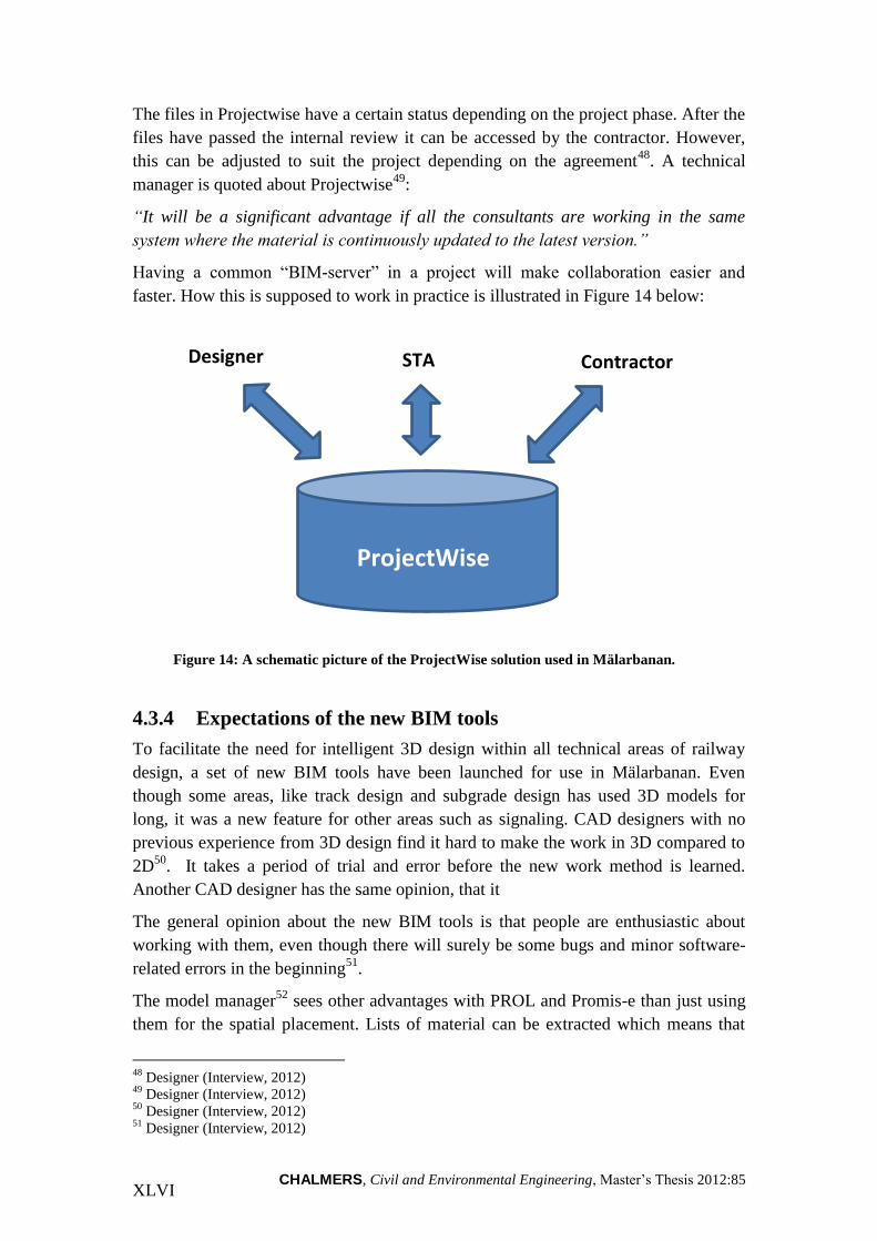
CHALMERS, Civil and Environmental Engineering, Master’s Thesis 2012:85 XLVI
The files in Projectwise have a certain status depending on the project phase. After the
files have passed the internal review it can be accessed by the contractor. However,
this can be adjusted to suit the project depending on the agreement48
. A technical
manager is quoted about Projectwise49
:
“It will be a significant advantage if all the consultants are working in the same
system where the material is continuously updated to the latest version.”
Having a common “BIM-server” in a project will make collaboration easier and
faster. How this is supposed to work in practice is illustrated in Figure 14 below:
Figure 14: A schematic picture of the ProjectWise solution used in Mälarbanan.
4.3.4 Expectations of the new BIM tools
To facilitate the need for intelligent 3D design within all technical areas of railway
design, a set of new BIM tools have been launched for use in Mälarbanan. Even
though some areas, like track design and subgrade design has used 3D models for
long, it was a new feature for other areas such as signaling. CAD designers with no
previous experience from 3D design find it hard to make the work in 3D compared to
2D50
. It takes a period of trial and error before the new work method is learned.
Another CAD designer has the same opinion, that it
The general opinion about the new BIM tools is that people are enthusiastic about
working with them, even though there will surely be some bugs and minor software-
related errors in the beginning51
.
The model manager52
sees other advantages with PROL and Promis-e than just using
them for the spatial placement. Lists of material can be extracted which means that
48
Designer (Interview, 2012) 49
Designer (Interview, 2012) 50
Designer (Interview, 2012) 51
Designer (Interview, 2012)
Designer
Contractor
ProjectWise
STA

CHALMERS, Civil and Environmental Engineering, Master’s Thesis 2012:85 XLVII
orders can be placed well in time before construction, and an earlier estimation of the
quantity take-off is possible.
4.3.5 Facility management data
The facility management is an important economic post when looking at a railway in
a lifecycle perspective53
but today it is unclear if the BIM model is to be used for this
stage in project Mälarbanan. There are possibilities to do this however, but it needs to
be coordinated with the facility management at the STA, and their practice today does
not include handling models54
.
A CAD designer55
means that it is a difficult question; today most of the facility
management data is delivered in the XML- and PDF-format, but in the future it would
probably be enough to deliver the BIM model only. The project leader56
means that
there are visionaries that want to change the structures around the facility
management and use the BIM model for this purpose. However this is something that
demands a deeper level of BIM before it is feasible.
The use of BIM models as deliverables for facility management is an important
question for the STA as an owner. A technical manager is quoted57
:
“We are still at a stage where we deal with plastic originals, and it is not an
advantage when we are about to implement BIM that we aren’t working with digital
data yet. We update the facility management data continuously but there are still
plastic originals left”
Around the country there are numerous signal boxes with plastic drawings over the
signaling system. The problem is that large investments are needed to transform the
data from analogue to digital form58
. Today this only happens during a reconstruction,
which means that there is still a long way to go.
The contractor argues that it is up to the owner to demand what kind of data they need
for the facility management, and that this is very different from project to project
depending on the owner59
. They are currently working with a large hospital project
where the owner has come far in terms of BIM use60
:
“They chose a system from the start where everything is in 3D all the way to facility
management, but at the same time another owner doesn’t have a clue”
52
Designer (Interview, 2012) 53
Designer (Interview, 2012) 54
Owner (Interview, 2012) 55
Designer (Interview, 2012) 56
Designer (Interview, 2012) 57
Owner (Interview, 2012) 58
Owner (Interview, 2012) 59
Contractor (Interview, 2012) 60
Contractor (Interview, 2012)
CHALMERS, Civil and Environmental Engineering, Master’s Thesis 2012:85 XLVIII
He also means that Finland is ahead of Sweden on the owner-side61
, they started
earlier with BIM and have developed more within this field in terms of demands and
regulations.
In the future there will most likely be more focus on the operation and maintenance
part of the BIM, since there is a big advantage to have a well-documented railway
facility to manage maintenance efforts62
. An example from the technical manager
highlights this was when a delivery of defective isolators was discovered. By the time
of the discovery they were already assembled across the county, and they had to be
identified manually which took a lot of time. This would probably have been easier if
BIM practices had been used also for the facility management63
.
4.4 Owner demands of BIM
The interviews showed that that the demands regarding BIM from the owner are very
few, or non-existing. Most of the CAD designers were not familiar with any demands
at all regarding BIM, but they knew what they were expected to deliver64
. A senior
CAD designer65
argues that the owner demands 3D or BIM models in some projects,
but that the requirements are diffuse about what the model should contain. A
technology coordinator66
means that there were no demands at all from the STA
during the procurement for Mälarbanan. Instead it was Vectura’s initiative to use BIM
and set the standards for the project. He continues67
:
“I haven’t seen it yet during procurement, but it won’t be long until it comes. For
example the Norwegian Public Roads Administration in Norway demands the use of
BIM in their procurements, and has done so for years”
Mälarbanan is not a specific BIM development project, as for example Bypass
Stockholm, and therefore the STA were clear about the fact that they do not have any
demands regarding the BIM use68
. The STA understands that this is a new technology
and that it will take some time before everyone is ready to use it. Instead of having a
list of demands they rather have a wish-list, aware that everything might not be
possible to include in the BIM model with the current design tools69
.
Also the respondents from the owner organization show the same picture, that there
are no demands regarding BIM yet. Instead they have a handful of pilot projects
which will help develop measures for the future. A technical manager70
is quoted
about the BIM demands:
61
Contractor (Interview, 2012) 62
Designer (Interview, 2012) 63
Designer (Interview, 2012) 64
Designer (Interview, 2012) 65
Designer (Interview, 2012) 66
Designer (Interview, 2012) 67
Designer (Interview, 2012) 68
Designer (Interview, 2012) 69
Designer (Interview, 2012) 70
Owner (Interview, 2012)

CHALMERS, Civil and Environmental Engineering, Master’s Thesis 2012:85 XLIX
“We are not yet there, we haven’t placed any demands on either designer or
contractor, and instead we have given them freedom to come with suggestions.
Vectura has presented a package that they think is good and which we use for now,
but as soon as the contractor comes that might have to be revised”
The construction manager at NCC means that the demands are very different
depending on the owner organization, where some are very far ahead in the
development compared to others who don’t have a clue71
. He also argues that it is
better now when the Swedish Rail Administration and the Swedish Road
Administration has merged into the Swedish Transport Administration, saying:
“Previously you could have one construction manager at the Swedish Rail
Administration, and one at the Swedish Road Administration, each with different
demands and with different content in the enquiry documentation. And sometimes they
have external consultants in charge of the design, which is also a problem”
4.5 Benefits from using BIM
4.5.1 Owner
It is generally the owner who gets the most benefits from using BIM in a project72
,
given the respondents’ answers. There are some capabilities that are mentioned more
frequently than others, including visualization, quality and cost cutting.
Visualization
BIM allows for earlier visualizations that can be used for different purposes73
; project
communication, review meetings, communication with the public. A design
coordinator is quoted74
:
“With BIM the owner can more easily see what is to be built, and they are usually not
experts but if they can see a 3D model of the structure it is easier for them to gain
understanding”
By using a BIM model less technically skilled persons can better understand the
difficulties in a project. In that way the participation increases from the owner during
the project phase75
. Anyone interested can see and really understand what it is they are
looking at. The model will make it possible to render advanced views, the model
manager says76
:
“You will be able to stand in the back garden and see the train pass, or you can look
out from the train window and see the landscape as it looks in the reality”
71
Contractor (Interview, 2012) 72
Owner (Interview, 2012) 73
Designer (Interview, 2012) 74
Designer (Interview, 2012) 75
Designer (Interview, 2012) 76
Designer (Interview, 2012)

CHALMERS, Civil and Environmental Engineering, Master’s Thesis 2012:85 L
Higher quality
Another important advantage with BIM is that the quality increases, both during
planning and construction. The CAD designers have to put more effort in the design,
they have to solve problems earlier and there will be fewer errors in the model once it
is delivered77
. A higher quality on the design documents means that fewer errors will
be made during construction, and there will be fewer deviations to be solved on-site.
The owner will also be able to see if a design is feasible early in the project, with a
given budget. This is due to a higher detail level and security, which makes it easier to
plan the project78
.
Communication and information
The 3D model can also be used for communication between the owner and the public
at an early stage in the planning process, for example to decide between alternative
designs of the railway79
.
Working and communicating with models also means that there will be less
information on paper. It makes the distribution of information both faster and more
accurate. The model will continuously be updated throughout the project so that
access to the latest version comes automatically. The owner, designer and contractor
will work from the same shared space in ProjectWise which means there will be fast
access to the information80
.
4.5.2 Designer
When BIM is implemented there will be more work to do for the CAD designers since
they are the ones developing the BIM model. Compared to the old work method, the
design phase will take up more time, which also means more income for the company.
But it has several advantages as well, and many of the respondents think that Vectura
will be a more attractive as an employer on the market with the use of BIM, since it
becomes more fun to work with81
. This way younger people with computer skills can
be attracted to the AEC industry how might have gone to the IT industry otherwise.
Better understanding
A better understanding between the different technical areas is another benefit for the
designers. A senior CAD designer is quoted82
:
“When working with models, it is easier to see what the other technical areas are
doing, and what effects it has, but also how you affect the others”
77
Designer (Interview, 2012) 78
Designer (Interview, 2012) 79
Owner (Interview, 2012) 80
Owner (Interview, 2012) 81
Designer (Interview, 2012) 82
Designer (Interview, 2012)

CHALMERS, Civil and Environmental Engineering, Master’s Thesis 2012:85 LI
Improved design review meetings
During the design review meetings it will be easier to see changes in the model when
viewed in 3D using Navigator, and by creating mark-ups to mark clashes. Previously
a 2D model has been used for the meetings which make it difficult to understand what
is shown, since symbols, lines and shapes are overlapping each other. A design
coordinator is quoted about the pre-BIM practice during these meetings83
:
“During a design review meeting all the layers in the 2D design file are active and it
is very difficult to see what you are looking at. All model files from the different
technical areas are mixed together in one plane; therefore a 3D design review model
is needed where everything is clearer”
Using a 3D visualization model for these meetings would make them simpler and
more efficient. It would even be possible to use conference software like
Communicator and the meetings would take less than half an hour for a design review
meeting compared to a few hours today84
.
4D-modeling
A 4D model is a useful tool for project planning, and this is something that will be
used in project Mälarbanan. As soon as the contractor is procured there will be
discussions about a practical solution for how to use the 4D model for time- and
production planning. According to the project manager the logistics is a very
important part in a project of this size85
. If the time dimension is added to the existing
3D model it would facilitate a more effective project planning.
Better multi-discipline collaboration
With the new work processes that come with BIM there will be better collaboration
within the project group. If the different technical areas all work in the same model
there it will be easier to detect clashes for example86
. There is potential to improve the
design review meetings with a common model, and also understanding among the
CAD designers87
.
In order for BIM to succeed at a high level, it demands that the collaboration
improves. This is not always the case though, and a design coordinator has experience
of this and mentions a partnering project where everyone thought that things would go
a lot easier. Instead the contractor wanted more than what was included in the design
documents88
. In project Mälarbanan the BIM server (see Figure 14) will work as a
digital repository which will improve the chances of an effective collaboration.
83
Designer (Interview, 2012) 84
Designer (Interview, 2012) 85
Designer (Interview, 2012) 86
Designer (Interview, 2012) 87
Owner (Interview, 2012) 88
Designer (Interview, 2012)

CHALMERS, Civil and Environmental Engineering, Master’s Thesis 2012:85 LII
Re-use of information
Even though the design and construction process between different projects may vary,
there are always a number of elements of construction that are similar from project to
project89
. Yet new design documents are being developed and reviewed for every
single project. A technical manager90
:
“During railway construction, you excavate down to a certain depth which is the
same no matter which project you look at, and also overhead power lines, tracks and
switches are the same more or less”
BIM can easily facilitate the use of old designs, since all information is stored in a
central project- or BIM server. For repetitive elements in the design and construction
process, this could save time and increase the efficiency.
Increased interaction designer-contractor
It is easy to change a design early in a project when nothing is determined. Later on
when there are more objects and details in the model it becomes harder. If the contract
form allows it the collaboration and interaction between designer and contractor will
become vital in order to come up with optimal solutions. BIM will work as a driver
for increased collaboration between the parties through the models.
4.5.3 Contractor
Production planning
With a time-plan linked to the BIM model it is possible to see the railway being built
virtually and according to the time schedule. This is a powerful tool which can be
used to control the production phase. The 4D simulation will be used in project
Mälarbanan and the project manager is quoted91
:
”4D and production planning is something we will discuss with the contractor once
they are hired; how we should do it in practice. We mustn’t forget that during a
construction like this the logistics plays an important role”
Logistics in a large project where the access to nearby laydown areas might be
restricted since there already is a built environment around the existing railway. If we
can make a better planning before the construction start we can be more efficient. The
material needs to arrive in time so that the production is not interrupted92
.
The contractor has used 4D in some projects, even though it is not so common today.
It is very different from project to project, and is generally applied on larger
infrastructure projects93
.
89
Owner (Interview, 2012) 90
Owner (Interview, 2012) 91
Designer (Interview, 2012) 92
Contractor (Interview, 2012) 93
Contractor (Interview, 2012)

CHALMERS, Civil and Environmental Engineering, Master’s Thesis 2012:85 LIII
Higher production efficiency
There will be a higher efficiency in the production phase, which in the long term
means a better profitability. A design coordinator94
mentions a road project which has
the same contract method as Mälarbanan – if they could design and build it cheaper
than the estimated cost they share the profit – and he claims they save a lot of money
from using BIM in this project.
Fewer errors
There will be fewer errors and deviations (CAWs) in a BIM project compared to a
traditional project. With better and more detailed design documents the number of
“resolve on-site”-problems will be fewer95
. By using a 3D model of the structure it is
easier to see the errors in the model instead of during construction.
Quantity take-off and bills of quantities
When all objects in the model are listed with attributes in a database, it is easier to
extract bills of quantities. With BIM the quantities will be more exact, and they can be
extracted earlier on in the design phase96
. Different designs can be tested and
evaluated, and cost estimations can be made from the bills of quantities. The material
is an important parameter in the budget for the project97
. If the quantities are more
exact it means that the right amount of material is bought.
Machine-guidance and mass optimization
Previously the surveyor’s assistant has been given plan and profile drawings from the
designer and from those documents developed a DTM for machine-guidance98
. Now
the model is provided by the designer. Sometimes the model needs to be modified
before it can be used for machine-guidance, but the idea is that it should work straight
from delivery. Once loaded into the on-board computer the machine can work more or
less non-stop, this makes the use of machines more effective99
.
Mass optimization is about minimizing the transport of masses, and in a large railway
project this is very important for the economy in the project. At some stretches there
is a surplus of masses, which could be used as fill material for other stretches where
there is a shortage. The project engineer is quoted100
:
“We cannot move around masses, as soon as there is an extra transport of misplaced
masses we lose the economy in the project since the margins are so small”
The longer the railway or road (it works pretty much the same way) the longer the
transports become and the more important is the mass optimization. For larger
94
Designer (Interview, 2012) 95
Designer (Interview, 2012) 96
Designer (Interview, 2012) 97
Designer (Interview, 2012) 98
Designer (Interview, 2012) 99
Contractor (Interview, 2012) 100
Contractor (Interview, 2012)

CHALMERS, Civil and Environmental Engineering, Master’s Thesis 2012:85 LIV
projects (above 50 million SEK) the contractor uses specialized software for this
purpose101
.
4.6 Challenges
Always when a new technology is introduced there are issues to overcome, and from
the interviews a number of different challenges have been identified. Some are related
to the technology, while other are related to legal matters, processes and roles.
4.6.1 Technology related challenges
To be able to design a detail-rich model in 3D all objects need to be available in the
database, or object library. At the moment the process of completing the object library
is undertaken. Today there are still some objects missing102
.
Another problem is the level of detail in the BIM model. Since Mälarbanan is the first
BIM railway project for Vectura it is up to them to set the standard103
. According to a
CAD designer it was hard to decide the level of detail, should bolts be included etc.
This led to a high level of detail, where bolts are included in the model.
A design coordinator104
claims that BIM is easier to implement in road projects rather
than railway projects since they don’t have the schematic technical areas electricity,
signaling and telecommunication. Moreover, when constructing a road there are not as
many objects around the road compared to a railway.
4.6.2 Interoperability challenges
There are risks with the data management and interoperability as well. Mälarbanan is
a long project with more than 15 years until completion, and the technical manager at
The STA is concerned about this105
:
“This is a very long project, and the question is whether the systems we use today will
still be in use when it is finished, we have to see to that there is a compatibility
between old and new so that we can make use of the information in the future”
Previously there were a lot of software-related issues with the different file formats
but now it is not as bad. Today the formats are more compatible with each other even
though the model still needs to be perfected manually by us106
.
Another problem that is of concern is that the current BIM pilot projects within
infrastructure have different outcomes; that they point out different directions and
standards107
. Different projects use different BIM technology and solutions, and it is
difficult to decide which technology to use.
101
Contractor (Interview, 2012) 102
Designer (Interview, 2012) 103
Designer (Interview, 2012) 104
Designer (Interview, 2012) 105
Owner (Interview, 2012) 106
Contractor (Interview, 2012) 107
Owner (Interview, 2012)

CHALMERS, Civil and Environmental Engineering, Master’s Thesis 2012:85 LV
In a railway project today the dominating design software used is Bentley’s
Microstation environment. Some technical areas use AutoCAD, for example bridge
design, and there could be some problems when transferring files from one system to
the other. Generally Microstation is better at importing AutoCAD files than the
opposite108
. There have been discussions about developing a neutral XML-based
format for overhead power lines. Some technical areas such as track use the landXML
format109
, which today has become an ISO standard.
The IFC format is interesting but currently it is not developed for railway projects. In
order for IFC to be suitable for a railway facility a complete model of the facility
needs to be developed – how should it be designed and what attributes should be
assigned to the objects110
. If all the systems had the same database model it would be
easier, but that is not realistic, according to a technical manager111
.
4.6.3 Structural challenges
Since BIM still is in the early days within the civil construction field, old practices are
still used which sometimes can oppose the positive effects from using it. One of the
fundamental benefits with BIM is that you create the data once, but you can use it
multiple times for different purposes. An example of when this didn’t work is from
Mälarbanan112
, where a 3D-model was developed by another design company at an
early stage in the project. But the STA used old practices and received a PDF of the
model, without the intelligence of a model file. So when Vectura started working with
the project they had to re-construct the model, spending many hours to re-do
something already done before113
. The design companies in the industry are a long
way ahead of the owner in the se of BIM. The project manager is quoted114
:
“If the owner has the right to material from the designer but doesn’t know what kind
of material is needed, then something is obviously wrong”
Another concern is that the largest owner, the STA, lacks necessary competence about
the implementation and use of BIM. Some experts within the organization have top
skills and knowledge, but the over-all level of knowledge is low115
. There are also
variations of knowledge within the designer and contractor organizations, the project
engineer at NCC says116
:
“Certain designers are far ahead in terms of BIM in some projects, but in others they
are behind. Certain persons have super skills, but in the office next to his, it is
virtually on a Stone Age level”
108
Designer (Interview, 2012) 109
Designer (Interview, 2012) 110
Designer (interview, 2012) 111
Designer (Interview, 2012) 112
Designer (Interview, 2012) 113
Designer (Interview, 2012) 114
Designer (Interview, 2012) 115
Designer (Interview, 2012) 116
Contractor (Interview, 2012)

CHALMERS, Civil and Environmental Engineering, Master’s Thesis 2012:85 LVI
There are also problems related to the differences between the road- and railroad
divisions within the Swedish Transport Administration and inferior communication
between the two. Instead of one vision they have two different117
.
A few of the respondents claim that the implementation of BIM is hindered by the
older generations within the AEC industry, which can be underlined by this quote
from the technical manager at the STA118
:
“Before we can succeed with a high level of BIM we need to wait for a generation
change at the Swedish Transport Administration, but also for the designers and
contractors”
The older generation still wants to look at paper drawings; they don’t want to look at a
computer screen119
. During the owner’s review of design documents for example,
more than half still want to see a paper.
The implementation of BIM has organizational impacts as well. New roles within the
projects need to be defined120
, such as a BIM coordinator. The BIM coordinator will
be a key person in a project, someone with expert skills and knowledge, who can help
the contractor with the model for example.
Another important problem is that the owner is not clearly demanding BIM in
infrastructure projects.
4.6.4 Juridical challenges
When dealing with models instead of paper drawings in a project it will raise
questions about the legal status of the model. In the project contract for Mälarbanan it
is clearly stated that a paper document is valued over a digital document like a model
file for example. In a procurement the STA currently uses paper drawings and not
model files121
. They want to change this practice and lawyers are currently looking at
the matter. The problem with model files is the version of it, which is easier to handle
with a paper drawing with a stamp. There are ways to deal with this, for example in
Microstation you can use a function called “Design History” which can be used to
track the version of a model file. 3D-PDF’s with stamps is another solution122
.
According to a model manager123
this is not a big issue in Mälarbanan due to the
collaborative project organization, where the aim is to work towards a common goal.
Vectura and the contractor together find out what documents the contractor needs to
build from and the Swedish Transport Administration have no demands on the design
documents, contrary to DBB procurement. He is quoted about another project124
:
117
Designer (Interview, 2012) 118
Owner (Interview, 2012) 119
Owner (Interview, 2012) 120
Designer (Interview, 2012) 121
Owner (Interview, 2012) 122
Owner (Interview, 2012) 123
Designer (Interview, 2012) 124
Designer (Interview, 2012)

CHALMERS, Civil and Environmental Engineering, Master’s Thesis 2012:85 LVII
“Yesterday I was at a meeting in a different project which was procured in a
traditional way, and they had big problems with the legal issues around the model”
The meaning of traditional procurement suggests that DBB or DB methods are used.
There are solutions to this problem already today, and OpenBIM has a contract for
digital design deliveries that can be used for this purpose125
. This contract determines
what the digital model should include, and its juridical status compared to the paper
document. NCC has used this for their DB projects where they can control the design,
but the STA has not used this yet according to the project engineer126
. But with the
model file valued over a paper drawing the problem occurs again with different
versions. The project engineer is quoted about versions and machine-guidance127
:
We had problems with this in the beginning, that model files are changed. They have
the same names but contain a different model. This could be dangerous, especially
when the model is transferred to the machine, how is the operator supposed to
know?”
4.7 BIM depending on the procurement
The general opinion among the respondents is that BIM is possible with all types of
procurements, although there are differences in the chances of succeeding with BIM
at a high level. It is important that the parties involved in a project start the
collaboration early and that they are at the same level. This can be emphasized by a
quote from a CAD engineer128
:
”I believe it’s good for the project to get the contractor’s opinion early. In all projects
there is collaboration between the designer, the owner and the contractor and if we
want BIM to work then it has to be on a level that is reasonable for all three”
If the contractor can use the model and build straight from it, then the production of
paper drawings can be skipped, meaning that time and money will be saved. It is
about communication between the parties involved129
.If there are three parties in a
project and one of them hardly knows the meaning of BIM, it is quite clear that there
will be problems. Also the technical manager at the STA agrees on this and means
that there is a big advantage if the contractor joins the project early130
. He sees
advantages with BIM especially in a collaborative project during the spatial placement
of the objects on and around the track131
. Since the design is more variable at early
stages it is easy to see how one change affects the other objects. He is quoted132
:
“During procurements where the contractor has a chance to affect the design early
on in a project, there are definitely more benefits with BIM”
125
Contractor (Interview, 2012) 126
Contractor (Interview, 2012) 127
Contractor (Interview, 2012) 128
Designer (Interview, 2012) 129
Designer (Interview, 2012) 130
Owner (Interview, 2012) 131
Owner (Interview, 2012) 132
Owner (Interview, 2012)

CHALMERS, Civil and Environmental Engineering, Master’s Thesis 2012:85 LVIII
The opinion on BIM depending on the procurement varies though, and a model
manager133
at the STA means that the DBB (Design-Bid-Build) approach is the best.
When a contractor is hired using DB (Design-Build), then the contractor also makes
the design documents, and there will be difficulties to succeed with BIM. On the other
hand, in a DBB procurement the STA contracts a designer to produce the design
documents and that is more suitable for BIM134
. But the chance of succeeding with
BIM in a project is also depending on the knowledge and skill level of the contractor,
the designer as well as the demands we have as an owner.
The procurement in project Mälarbanan
According to the design phase manager135
the procurement is DBB, even if it is done
in a form of increased collaboration. He is also talking about the DB procurement and
there is not a problem in either one of the contract methods to handle the information
flow digitally. He predicts a smooth handling of the documents during the project;
instead of receiving several file folders a USB memory can hold the same
information.
The model manager136
argues that it is important in a project like Mälarbanan to adapt
a common picture of BIM between the designer and the contractor to make things
clearer. By doing so it is easier to produce the correct information and get a more
effective handling of the process.
A common economic incentive to share among the parties in a project, works as
motivation to increase the efficiency. An example of this is the procurement in project
Mälarbanan where there are bonuses of 50 million SEK if certain goals are
accomplished in time. The project manager explains how this works137
:
“The parties in Mälarbanan chose to enter a form of collaboration with a standard
price that we believe in, that the contractor believes in, and the owner believes in.
Then our goal is to try and end up below that price”
133
Owner (Interview, 2012) 134
Owner (Interview, 2012) 135
Owner (Interview, 2012) 136
Owner (Interview, 2012) 137
Designer (Interview, 2012)

CHALMERS, Civil and Environmental Engineering, Master’s Thesis 2012:85 LIX
5 ANALYSIS AND DISCUSSION
This chapter is based on the theory in Chapter 3, the result from the interviews in
Chapter 4, and the author’s own opinions.
5.1 Different views on BIM
An understanding of how BIM is perceived in the railway industry today is necessary
to know where we stand and how we can develop from there. The interviews showed
that there is not a common picture of BIM among the players in the AEC industry.
The level of knowledge varied among the respondents, regardless of if they come
from the owner, designer or contractor organization. The view of BIM is usually
revolving around a 3D model but with more intelligence. If we imagine a project team
where some of the participants only have a vague idea about what BIM really is it can
cause friction in the collaboration. It seems as if the designers and contractors are
ahead of the owner (the STA) in terms of BIM use, and have developed a broader
insight into how it can be used in projects.
When asked about the picture of BIM many of the answers revolved around the
benefits from using BIM such as visualization, machine-guidance and so forth. The
organizations look at how BIM can impact their part of a project; how they can
benefit from it. This is natural, but it also indicates that there is no deeper
understanding of the full extent of BIM. The parties involved in a project need to look
not only to their own part, but also have an understanding and a dialogue with the
other parties involved.
Some of the respondents answered that they have used certain BIM features in earlier
projects. The contractor had been using machine-guidance for up to 10-15 years and
was very familiar with that aspect. However it was not clear if the digital terrain
model used in the beginning was generated automatically from a BIM model. Another
example is from the designer where quantities have been extracted from 3D models
since the late 90’s, but that is also an isolated benefit from using BIM. Not until the
last couple of years there has been serious talk about BIM in the industry, some of the
respondents had never before heard the word until they started working with project
Mälarbanan, or the internal BIM project at Vectura. With these examples it is clear
that although some aspects of BIM have been used before, it is not until now that the
bigger picture is seen.
If we look at BIM in a wider perspective, considering the BIM lenses in Chapter 3.3.2
we can establish that both Vectura and the contractor belongs to the process field, as
users of the technology for their work. Also the STA as an owner belongs to this field,
but they also have another, more important role as a regulatory body within the policy
field. Today’s situation can be compared to a stalemate where not much is happening
in the policy field. Despite this fact the designers and contractors are well on their
way in terms of BIM implementation and use.

CHALMERS, Civil and Environmental Engineering, Master’s Thesis 2012:85 LX
5.1.1 From Vectura’s point of view
BIM is described as a tool and a process. The process is the creation of information to
develop an intelligent 3D model; a process that starts as soon as the design phase is
initiated and lasts until the product is finished, using BIM tools such as RailTrack
running on Microstation. The view on BIM from Vectura can be seen in Figure 15.
Figure 15: The resulting picture of BIM can be seen as both a tool and a process.
Vectura has historically been separated in different organizations, one working with
railway design and one with road design. This means that there are also two different
approaches to BIM and how it should be implemented in practice. For example, the
road and railway divisions at Vectura use different technical solutions, i.e. different
BIM tools for the design. Basically the two divisions think in the same way but there
are details that differ. Long code-strings are used by the road division to label the
different layers in their design files, while the rail division uses more logic names for
the layers. This could cause problems when developing one general company BIM
policy at Vectura, since people with a background in the road division prefers to work
with their tools and work methods, and the other way around.
5.2 Implementing BIM within the railway sector
The internal BIM project
Although there have been an internal project at Vectura about the implementation of
BIM within the railway division, not much has happened since that project was
completed. Now six months have passed which means that the validity of the results is
decreasing in a changeable environment. Although most people are talking about BIM
in enthusiastic words, more needs to be done from top-level management to further
encourage it. Currently there is no plan for a continuation of the project and no BIM
adoption plan has been developed. Mälarbanan as a pilot project functions as a BIM
workshop for Vectura where they can try new BIM technology and work processes.
BIM
Tool Process

CHALMERS, Civil and Environmental Engineering, Master’s Thesis 2012:85 LXI
The result from Mälarbanan will help to guide the continued BIM adoption of both
software and staff training.
No completed BIM projects yet
There are several outspoken BIM pilot projects within the infrastructure sector of the
AEC industry, such as Bypass Stockholm. However, most of these projects have not
yet reached the construction phase, meaning that the experience from those projects
only include the design phase where intelligent 3D design and visualization are the
most notable benefits. Since the BIM use is in the early years within infrastructure it
seems that there are no projects yet that have gone through all the project phases;
design, construction and operation. The lack of experience from real projects makes it
hard to show the effects from using BIM on the economy of a project. Even with
completed projects at hand it might be difficult to quantify the profit from using BIM
in a project. For that all BIM-related costs must be isolated, analyzed and compared
against the amount of money saved from using BIM.
Comparison to the BIM implementation steps
Considering the steps for implementing BIM described in Chapter 3.5.5 and applying
them on Vectura, we can ascertain that more can be done. Some of the steps are
fulfilled while others need to be attended to. For example, there is neither an existing
BIM adoption plan covering all aspects of the company’s business, nor a team of
managers responsible for implementing the plan and monitoring the performance.
Even though there have been some previous, smaller projects which has made use of
certain aspects of BIM such as model-based collaboration, Mälarbanan is the large
BIM project where useful experience will be gained for Vectura. The initial results
can then ideally be used to educate and guide the staff in the continued BIM adoption.
It is difficult to quantify the economic benefit from using BIM, but if that somehow
could be monitored in project Mälarbanan it could be used as further argumentation.
There were also opinions expressed in the interviews that a new work method for
CAD designers working with BIM need to be developed, or adapt the current method.
Contractual documents and relations to business partners need to be overlooked and
adapted to the new business processes. This is something that Vectura needs to do in
agreement with other industry players such as the STA and contractors. Clearer
demands and more standardization in the industry will have positive effects on the use
of BIM.
5.3 Status of BIM in the railway division
BIM within railway design is still in in its early days, but the experiences from project
Mälarbanan will hopefully change this and drive the implementation of BIM forward.
It is an area subject for a rapid development and technology and practices changes
quickly. The ambition with BIM in Mälarbanan is set high, but the project is still at an
early stage and has a lot to prove yet.
The different stages of BIM maturity described in Chapter 1.1.1 will be used when
discussing the status of BIM in the railway division. The first stage is pre-BIM which

CHALMERS, Civil and Environmental Engineering, Master’s Thesis 2012:85 LXII
is much depending on 2D documentation, or 3D modeling lacking intelligence. This
can be compared to the situation at Vectura before the new BIM tools were launched.
That is, some technical areas work with 3D modeling while others continue to work in
a 2D environment. The generated 3D models lack intelligence since there are no
attributes linked to them at this stage.
With the introduction of the new BIM tools, it means that the requirements of BIM
stage 1 is fulfilled – working with object-based 3D design by using the RailTrack,
PROL and Promis-e applications. The difference between BIM stage 1 and BIM stage
2 is that the previous one still depends on collaborative practices comparable to a pre-
BIM stage, whereas the latter includes a more extended collaboration between
different disciplines and even between different project phases. An example of this is
the interaction between designer-contractor which is significant for BIM stage 2;
model-based collaboration. This suggests that Vectura belongs to stage 2 according to
Figure 16 below.
Figure 16: An indication of Vectura's position in terms of BIM maturity, BIM stage 2.
To reach the third stage a more integrated approach is needed with a deeper
collaboration between the parties, and also more focus on the whole life-cycle of the
facility. Some features already exists that will drive the development further towards
network based integration such as the ProjectWise solution from which all the parties
can work from and exchange information. The ultimate goal of BIM is to achieve an
integrated project delivery, and that stage is far from the reality today. But as the
parties get more experience from working under more collaborative forms, the IPD
approach is not an unreachable goal in the future.
In conclusion, it seems as if the civil sector in the AEC industry is catching up with
the more developed building sector in terms of BIM maturity. The development is fast
and driven by the designers and contractors.
If we consider BIM as both a tool and a process, it is the latter that needs most
development. One of the most difficult aspects of a technology-driven change is not
the technology itself but the associated work methods. New collaborative work
methods need to be developed, suitable for the new technology.
Pre-BIM BIM Stage 1
Object-based modeling
BIM Stage 2 Model-based collaboration
BIM Stage 3 Network-
based integration
Vectura

CHALMERS, Civil and Environmental Engineering, Master’s Thesis 2012:85 LXIII
5.4 Benefits during design, construction and operation
Although there are many benefits from using BIM, the whole lifecycle of a structure
needs to be considered to get the most of them. The process of railway planning and
design as was described in Chapter 3.1 is very long and can take many years to go
from idea to design and construction. After the construction of the railway is
completed it is handed over to facility management which will operate and maintain
the railway for a long period of time. Bearing this in mind the process from Chapter
3.1 can be simplified to consist of three major parts: design, construction and
operation. In Figure 17 on the next page the identified benefits are listed where they
can be applied during the project.
Benefits like improved communication, visualization, quality and collaboration are
naturally not associated to a specific project phase.

CHALMERS, Civil and Environmental Engineering, Master’s Thesis 2012:85 LXIV
Figure 17: Some of the identified benefits from using BIM throughout a project.

CHALMERS, Civil and Environmental Engineering, Master’s Thesis 2012:85 LXV
5.4.1 Changes in the design curve
The design process will change when BIM is used in a project. As the result showed,
the CAD designers will have to work more hours in the beginning of the project.
Design changes made early in a project are not as costly as changes made in the latter
design stages. With a BIM design process the changes to the design will not be as
costly, since they will be identified and resolved earlier. This is illustrated in Figure
18 below.
Figure 18: The design curve changes with the implementation of BIM (Post, 2007)
In a pilot project like Mälarbanan there is also the need to train staff to use the new
tools, which demands even more effort. A comparison to a traditional design process
shows that the peak effort occurs later in the project phase. The BIM start-up costs are
a big concern mainly for smaller firms, but that should not be a problem for Vectura.
Software licenses are already purchased for the necessary BIM tools. However, the
design process needs to be changed to better fit the new BIM tools. Vectura has
developed a work process which the CAD designers have used previously. This might
need to be adapted to a BIM design process. For example, it is important that the
design process is synchronized according to the design review steps and the status of
the files in ProjectWise.
5.4.2 How can Vectura benefit from BIM?
Vectura has the responsibility for developing the design documentation used for
construction. This is one part of the whole lifecycle, which means that the benefits for
Vectura are normally limited to the design phase, although in a project like
Mälarbanan Vectura is more actively participating in the construction phase, as a
result of the collaboration with the contractor. There are many benefits for Vectura
from using BIM, although some require a more integrated and higher level of BIM
and more development to be realized.

CHALMERS, Civil and Environmental Engineering, Master’s Thesis 2012:85 LXVI
A natural starting point is to use the BIM tools to produce an object-based 3D design
of the railway facility. That all the technical areas can work in 3D will enhance early
multi-discipline collaboration and understanding among the CAD designers. Using
Bentley Navigator a 3D model for visualization and simulation can be generated and
used for project meetings. This will clarify design review meetings and make more
effective, compared to using the old 2D practice. Clashes can be tagged with the
create mark-up function, and more accurate quantities can be extracted from the
model. Consistent 2D drawings for construction can be extracted at any stage of the
design. Design errors and CAWs will be detected before the construction phase which
means they will be cheaper to resolve. The overall quality of the design will improve
with better understanding from the persons involved in the project team. BIM will
allow for re-use of information within a project, and possibly between projects as
well. Another advantage is that BIM can provide better feedback and follow-ups after
the project is completed, to learn from the experience. This is not prioritized today
since there is no time, but it is desired by the CAD designers.
In combination with the contract method “Extended collaboration” there will be a
natural interaction between designer and contractor. This means that they can come up
with solutions together, and the contractor has a chance to impact the design with
ideas and constructability know-how. It will lead to a more effective and production-
oriented design. Powerful 4D-models can be used for project planning, where objects
in the model can be linked to a time frame and visualized accordingly.
As the BIM use spreads within infrastructure projects it is important to keep up with
the changes. There will be more demands about using BIM in new projects. Therefore
it will be a significant advantage to have knowledge and experience from BIM in
upcoming procurements, providing an important strategic capability for the company.
It is a competitive advantage to be first with BIM, and even though other design
companies are also implementing it, Vectura can learn a lot from using it in project
Mälarbanan. At an early stage in the implementation it is important to have an
iterative approach to the process and continuously improve it. Working with the latest
cutting-edge technology will also attract skilled employees and improve the status of
Vectura as an innovative company in the industry.
More information and functionality can be built into the model in the future. 4D-
models are already here, 5D-models with cost analysis will most likely be developed
soon and then other capabilities can be built into the model if desired.
Building Information Modeling works well with lean construction. Those two factors
combined with an IPD project delivery will further increase the productivity and
minimize the waste generated. This way a more environmentally sustainable design
and construction process is possible.

CHALMERS, Civil and Environmental Engineering, Master’s Thesis 2012:85 LXVII
5.5 Hinders and challenges
Chapter 3.5 gave an insight to some of the challenges with BIM implementation. It is
true that the designer as the key adopter does not benefit most from the use of BIM.
However, new business practices such as the procurement in Mälarbanan gives
economic incentives to all the parties involved: they get to share the profit if they can
build a cheaper railway facility. This suggests that Vectura as a key adopter does get
rewarded for the extra effort needed to implement BIM. Furthermore there is the
subject of collaboration challenges, which is a result of different practices among the
participants in a project, i.e. if the contractor uses traditional paper-based drawings
and the designer uses digital models. This could be a problem but as the contractor not
yet is procured it is too early to know if this will be a problem or not.
5.5.1 Legal status of the model
There is however other more concerning barriers to BIM, both theory and empirics
point out that the current contract models do not encourage the use of BIM. The legal
status of the model needs to be at least equal to that of a printed drawing. For example
in Mälarbanan, it is clearly stated in the contract document that a paper document is
valued above a digital document. This paragraph has different meanings depending on
its context. In a project like Mälarbanan where a collaborative framework is being
used it is not as much of a problem as it would have been in a traditional approach.
The transition from paper-based to model-based collaboration is made more difficult
by one small contract paragraph. Contracts used in BIM projects should encourage the
use of digital deliveries and not the other way around.
OpenBIM has developed a document for digital deliveries which can be used as an
attachment to a regular contract. In the contract the file format is stated, as well as
information of where the digital data should be delivered, for example to a project
server. NCC has been using this contract for digital deliveries in other projects and
they are satisfied with it.
5.5.2 Technical challenges - interoperability
One obvious obstacle to overcome when implementing BIM is linked to
interoperability. The ideal situation would be if all the parties work in just one BIM
model, using the same software. In reality this is not the case however. Not every
party uses the same software and it is not possible to use a single software for every
possible task there is. It would result in an overly complex program. Vectura uses the
Microstation environment for railway design, but in a project certain disciplines use
other, for example AutoCAD is used for bridge design. This results in two different
formats, DGN from Microstation and DWG from AutoCAD. It is possible to import
and export files between the different programs, generally Microstation is better at
importing DWG files than vice versa. But when exporting files from one program to
another does not guarantee that all the information is included and that the model
looks the same in the other program. Known interoperability problems are related to
line widths and colors, which might not appear the same after import from different

CHALMERS, Civil and Environmental Engineering, Master’s Thesis 2012:85 LXVIII
software. However, according to the interview responses the interoperability works
rather well with only a few problems linked to different file formats.
Then there is also the interoperability problem with different file formats and how
they might change in the future and not be usable any longer. In a long project like
Mälarbanan, with many years until completion, it is important that the file formats
used today also will be useful in the future. The software needs to be backwards
compatible so that also old file formats can be used without having to convert them. A
good example of this is that the latest version of Microstation can open files created
during the 1980’s.
The 3D object library will cover as much as possible of the railway facility. A smaller
object library from another project was provided which then was expanded with more
objects. There were some initial problems with the level of detail in the objects, as
well as how they should be connected to other objects. This problem is now solved by
using hook-points for insertion, and detailed object information placed in a database.
Future projects will use this object library so the development work is well invested
for the future. Then it needs to be continuously updated throughout the project.
5.5.3 Different skill levels and vague owner demands
There are differences in how far the different players in the AEC industry have come
in the BIM implementation. The STA, as the largest owner within infrastructure, is
still learning how to implement and use BIM in projects. They can be perceived as
being passive and waiting for the market to drive the development forward. This
relation should be the opposite and the STA as an owner should lead the development,
but the empirics indicate that both contractors and designers are ahead.
To support the implementation of BIM for the contractors and designers the Swedish
Transport Administration needs to develop a set of regulations and requirements for
the use of BIM in projects today. As the situation is today, there are no regulations at
all when it comes to BIM. According to the consultants at Vectura, and also NCC,
there are no demands on the use of BIM in infrastructure projects. This is one of the
major reasons why the implementation takes so long. It can be compared to a catch 22
situation where the STA are biding their time, not wanting to formulate a set of
regulations until the matter is properly investigated. Meanwhile the designers deliver
information traditionally according to the current practice, since there are no demands
saying otherwise in the enquiry documentation.
An example that highlights the need to change the current practice to better facilitate
the use of BIM-related models and processes is from Mälarbanan where the STA did
not demand the digital model that was developed by another designer before Vectura
was procured. Instead of delivering the model, a PDF drawing was handed out to
Vectura which meant that they had to develop the same model again, costing many
hours re-do. This is destruction of information and is an example of how BIM calls
for a change in the current practice. The owner needs to be clear about the demands
from the beginning and know what to ask for.

CHALMERS, Civil and Environmental Engineering, Master’s Thesis 2012:85 LXIX
5.5.4 What happens after the construction phase?
If we consider BIM in project Mälarbanan, only the design and production phase are
included in the current plans. Focus is on using the new BIM tools to work in a
common intelligent 3D environment, improve the project meetings, plan the
construction phase effectively and develop solutions in collaboration with the
contractor. It is beyond doubt that BIM will make the design and construction process
more effective, but still the fact remains that the facility management phase is not
included in the plans today. A concern is that much of the intelligence in the BIM will
be destroyed in the interface when the railway is handed over to facility management
(between construction-operation). The model files that describe the whole railway
facility might not be used for operation once construction is completed. Figure 19
below shows the different project phases and information flow.
Figure 19: Shows the different project phases and the information flow in the interface between
them.
Between the design and construction phase this is not a problem since they work
together to come up with solutions. This is illustrated by the two-way arrow in Figure
19 above, symbolizing the exchange of information.
However, if we look at what happens after the construction phase, it is more unclear.
The function within the STA responsible for the operation of the infrastructure is
currently looking into the matter to see how they can make use BIM for operation and
maintenance. Technical questions remain about which digital formats to use for
facility management and to make sure that the interoperability is ensured so that the
formats used today will be useful also in the future. If the BIM model could be used
for facility management it would mean that the whole lifecycle of the facility will be
taken into account and the benefits from BIM will increase when using it from design
through construction to operation. As we saw in Chapter 3.4.4 the handover of facility
information will be easier and it can be used to improve and integrate facility
operation and management systems.
At the moment the level of integration of BIM seems to be high in the design process,
lower in the construction phase and very low or absent in the operation phase. This is
something that needs to be changed in order to maximize the use of BIM. In project
Mälarbanan the parties involved does not include the one responsible for the operation
and maintenance of the railway. If that function of the STA was actively participating
Design Construction Operation
? Information flow

CHALMERS, Civil and Environmental Engineering, Master’s Thesis 2012:85 LXX
in the project from the start a higher level of BIM could be realized, and a more
effective handover after construction would be possible.
5.6 BIM depending on the procurement
The procurement is an important factor when discussing BIM, and has a great impact
on the result in the end. Most respondents agree that a contract method that allows for
an early collaboration between the different parties involved in a project is more
suitable. The chance of succeeding with a BIM project is also very much dependent
on the knowledge and skill level of the owner, designer and contractor organizations,
as well as the will to work collaboratively.
In a DBB procurement the owner, designer and contractor are separated which means
that the different project phases design, construction and operation are fragmented.
Between the different phases there is a handover of information (design documents
for example) which can cause problems. The contractor might not be able to use the
model created by the designer, and therefore has to develop his own model to use for
machine-guidance for example. With a DBB procurement there is an obvious risk that
information and intelligence will be destroyed in these handover phases since the
parties involved are separate entities. An example of this was the case in Mälarbanan
when the first 3D model was developed, only to be delivered to the STA as a PDF,
leaving out all the intelligence. In a more fragmented design and construction process
these problems are more common, and therefore the DBB approach is not a suitable
procurement for a BIM project.
The DB procurement is better since there is not the same degree of separation
between the contractor and designer. It means that information can be delivered more
seamlessly between the two. But there is still not the same collaborative framework as
the IPD approach which suggests that the BIM use will not be as effective. The owner
and the designer/contractor entity are still separated which means that for example
legal issues can arise concerning model files, versions and information ownership.
5.6.1 Mälarbanan – a step towards IPD
BIM without collaboration between the parties in a project is possible but not
recommended. It can be done, but that is not an efficient way to go about it. Many of
the benefits from using BIM are destroyed then. Instead BIM should work as a
platform for collaboration. According to Bilal Succar the ultimate goal with BIM is to
achieve IPD – Integrated Project Delivery. If we look at the procurement in
Mälarbanan, it is collaboration between the owner, designer and contractor. The
contract method encourages this with a common economic incentive and additional
bonuses for the parties involved to share. Even though it is not clearly an IPD project
it has some of the characteristics of one. This has several benefits, and the most
CHALMERS, Civil and Environmental Engineering, Master’s Thesis 2012:85 LXXI
important is of course gained from a high level of collaboration already at an early
stage.
The extended collaboration procurement also means that legal issues are less of a
problem in Mälarbanan, since they are working together towards a common goal – to
build a cheaper but still qualitative railway facility. The experience concerning legal
issues in other projects that have been procured traditionally is that it is a much bigger
problem in those projects. Normally formal design documents are produced and then
approved by the owner, but in this case the designer only need to produce what is
needed by the contractor to start the construction. Problems that do occur during the
project are solved together in Mälarbanan, and the risk as well as the potential bonus
money is distributed among the parties. However, there are still things that can
improve in the contractual documents concerning the legal status of the model. As the
contract stated a paper document is valued higher than a digital document, and this
can cause problems when the exchange of information is digital and centered around
model rather than paper-based. The contractual language should instead encourage the
use of models as deliverables, since it is a BIM project.
5.7 Suggested changes
In all the interviews the respondents were enthusiastic about using BIM with all its
benefits, but there is still a long way to go before it will be integrated throughout the
whole lifecycle. As we saw in Mälarbanan, BIM is only used for two thirds of the
three phases, since operation and maintenance is still not there yet. In the future this
should be considered already when starting a project, so that facility management can
be integrated in the BIM model.
Since BIM within the railway sector today is still in an early and developing phase an
iterative approach is recommended. We need to learn from previous experiences and
use them to develop the technology, as well as new processes and roles. Large owners
such as the STA need to develop new contract terms to avoid the legal issues that
come with the use of BIM and model collaboration. Today the STA can be perceived
as being too passive and only watch the development instead of leading it. The
demands about using it should also be sharper, what should the model include, what
are the deliverables, which file formats should be used and so on. BIM standardization
efforts could also be done at a governmental level, to further encourage and make
BIM use easier in practice.
The interfaces between the different design stages and between the project parties also
need to be clarified. This can be helped from an iterative approach where feedback is
given on the material delivered, but there needs to be time assigned for that in the
projects. The design process which previously was carried out first, and then handed
over to the contractor will now be more integrated and production-oriented.

CHALMERS, Civil and Environmental Engineering, Master’s Thesis 2012:85 LXXII
BIM is still a work in progress, and as it develops and becomes more widespread the
impact will be more apparent. It will contribute to a closer collaboration; make the
construction process faster, cheaper and with fewer errors.

CHALMERS, Civil and Environmental Engineering, Master’s Thesis 2012:85 LXXIII
6 CONCLUSIONS
The research questions from chapter 1.3 are used as a framework for the conclusion
chapter together with the result from theory, empirics and the analysis.
The view of BIM
There is not a common view on BIM, and the knowledge varies greatly both between
the companies in the AEC industry, as well as within the companies. These different
skill levels can cause collaboration problems in a project. The performed interviews
show that few parties have a uniform picture of BIM; instead they tend to see mainly
to their part. The overall picture of BIM is very positive though, and many of the
parties in the industry are currently implementing it in their business.
Building Information Modeling is a term that has been used the last couple of years
and there is limited experience from it. Some capabilities of BIM have been used for
several years, such as machine-guidance and extracting quantities from a 3D model.
However, a deeper understanding of BIM in a lifecycle perspective is necessary to
receive all the positive effects throughout a project, and also after the handover of the
completed facility.
BIM is described as both a tool and a process. The tool is the BIM software used for
designing the facility, and the process is the creation of input information to the
model.
What is the status of BIM use in the railway sector at Vectura?
The use of Building Information Modeling within the railway sector is in its early
days, the ambition in Mälarbanan is set high. Object-based modeling is used for the
design, and the collaboration is based on models rather than pre-BIM paper based
practices. Considering the BIM maturity stages and the use of BIM in Mälarbanan, it
suggests that Vectura is at BIM stage 2: model-based collaboration.
The level of integration of BIM seems to be high in the design process, lower in the
construction phase and even lower in the operation phase. This needs to be changed in
order to maximize the benefits of BIM.
The civil construction sector is catching up with the building sector where BIM has
been used longer and is more widespread. The development is fast and it is driven by
the design companies and the contractors. There are still large differences when it
comes to BIM maturity though, depending on the project and the participants.

CHALMERS, Civil and Environmental Engineering, Master’s Thesis 2012:85 LXXIV
What are the benefits and challenges of implementing BIM in a large railway
project like Mälarbanan?
There are many benefits from implementing BIM in a railway project, throughout the
different project phases. The whole lifecycle needs to be considered to get the most of
BIM.
Extended collaboration from an early stage in the project is both demanded and
enhanced by the use of BIM, across companies as well as within them. There will be
synergistic effects when using a suitable contract method with BIM.
Building Information Modeling can be used to visualize, improve project meetings,
better understanding and communication, higher quality of the design, extract
accurate quantities earlier, detect clashes, lower the number of design errors and
CAWs, increase interaction and understanding between technical areas, re-use
information throughout the project, improve the feedback and follow-up of the
deliverables, increase integration between designer and contractor leading to a more
production-oriented design, use 4D models for project planning, attract new
employees. BIM experience and skills will be important in upcoming procurements as
a strategic capability.
The legal status of the model is a barrier when implementing BIM. The contractual
situation today states that paper drawings are valued over a digital drawing, which is a
problem when model-based working and communicating is practiced. Another barrier
is that there are vague demands about BIM in civil construction projects from the
largest owner, the STA. A clear definition of BIM needs to be established, as well as
clearer demands on the content of the model. Technical challenges with the new BIM
tools remain, and also the interoperability between different applications.
What type of procurement is most suitable for a BIM project?
Considering the three different contract methods studied (Design-Bid-Build, Design-
Build and Integrated Project Delivery) it is clear that the IPD approach is the most
suitable for BIM projects. IPD and BIM will give synergistic effects since they both
demand and provide an early collaboration within the project team.
The DBB approach is very common today, but it remains a fragmented process where
the owner, designer and contractor are separated. BIM will be much more efficient in
a collaborative environment. There is a large risk that information and intelligence
will be destroyed in the interfaces between the different phases.
The DB approach is better since there is a high level of interaction between designer
and the contractor, often it is one single entity.
The most suitable procurement is integrated project delivery (IPD), and the Extended
Collaboration contract method used in Mälarbanan is a step towards reaching there. It
works well with the collaborative framework provided by BIM, and there will be
positive synergistic effects from using BIM with a collaborative contract method.
CHALMERS, Civil and Environmental Engineering, Master’s Thesis 2012:85 LXXV
6.1 Future research
When writing this master thesis I learned a lot about BIM in civil construction
projects but there were also some questions that were raised or remained unanswered
afterwards. They are listed below and could provide ideas for future studies.
Further case studies: It could be interesting to make a case study on a project
that has reached further than the design stage. How can BIM be used in the
production phase, and how much money or time can be saved throughout a
project?
BIM for facility management: What needs to be done before the BIM model
can be used to operate and maintain a railway facility for example. What
should the model contain to be used for this purpose?
Legal status of the model: Today paper documentation is still used as a
contract document, and is valued above a digital model. How can the
contractual documentation be changed to better suit BIM projects?

CHALMERS, Civil and Environmental Engineering, Master’s Thesis 2012:85 LXXVI
7 REFERENCES
Ashcroft, Howard (2009): Building information modeling: A framework for
collaboration. (Electronic) PDF-format. Available:
http://www.myscl.org/publications_7_1_3.pdf
Bentley (2012a): Microstation. (Electronic) Available: http://www.bentley.com/en-
US/Products/microstation+product+line/ [2012-05-03]
Bentley (2012b): Engineering Information Management and Project Collaboration
Software. (Electronic) Available: http://www.bentley.com/en-
US/Products/projectwise+project+team+collaboration/ [2012-05-03]
Bentley (2012c): 3D Rail Infrastructure Design and Maintenance Software.
(Electronic) Available: http://www.bentley.com/en-US/Products/Bentley+Rail+Track/
[2012-05-03]
Bentley (2012d): Power Rail Overhead Line. (Electronic) Available:
http://www.bentley.com/en-US/Products/Power+Rail+Overhead+Line/Product-
Overview.htm [2012-05-03]
Bentley (2012e): Promis-e. (Electronic) PDF-format. Available:
ftp://ftp2.bentley.com/dist/collateral/docs/promise/promise_datasheet.pdf [2012-05-
03]
BuildingSMART (2012): Model – Industry Foundation Classes (IFC). (Electronic)
Available: http://buildingsmart.com/standards/ifc [2012-04-06]
Drogemuller, Robin (2009): Can BIM be Civil? (Electronic) PDF-format. Available:
http://eprints.qut.edu.au/27991/ [2012-02-03]
GSA (2007): BIM Guide Overview. (Electronic) PDF-format. Available:
http://www.gsa.gov/graphics/pbs/GSA_BIM_Guide_v0_60_Series01_Overview_05_
14_07.pdf [2012-02-25]
Infomap (2012): GPS Machine Guidance FAQ. (Electronic). Available:
http://www.infomapsurveys.co.uk/gps/faq.htm [2012-04-29]
Jongeling, R (2008): BIM istället för 2D-CAD I byggprojekt. (Electronic) PDF-
format. Available: http://epubl.ltu.se/1402-1528/2008/04/LTU-FR-0804-SE.pdf
[2012-03-16]
NCC (2012): About NCC Construction Sweden. (Electronic) Available:
http://www.ncc.se/en/About-NCC/NCC-Sweden/NCC-Construction-Sweden/ [2012-
04-25]
OpenBIM (2012): Om OpenBIM. (Electronic). Available: http://www.openbim.se/
[2012-04-05]

CHALMERS, Civil and Environmental Engineering, Master’s Thesis 2012:85 LXXVII
Palmer, J & Pressley, S (2009): Civil Information Modeling and Building Information
Modeling. (Electronic) PDF-format. Available:
http://onlinepubs.trb.org/onlinepubs/circulars/ec145.pdf [2012-05-03]
Patel, R & Davidsson, B (2003): Forskningsmetodikens grunder: Att planera,
genomöra och rapportera en undersökning. Studentlitteratur: Lund.
Post, M. Nadine (2007): Structural Engineering Transition to 3D Digital Design Is
Toughest for Small Firms. (Electronic) Available:
http://enr.construction.com/news/buildings/archives/070523.asp
SCB (2012): Tillväxt och produktivitet (Electronic). Available:
http://www.scb.se/Pages/List____254962.aspx [2012-02-13]
Steel, J., Drogemuller, R., Toth, B: (2010): Model interoperability in building
information modelling. P. 99-109.
Succar, B (2009): Building information modelling framework: A research and
delivery foundation for industry stakeholders. (Electronic) PDF-format. Available:
http://www.sciencedirect.com/science/article/pii/S0926580508001568 [2012-04-04]
Trafikverket (2012a): Så blir väg och järnväg till. (Electronic) Available:
http://www.trafikverket.se/Privat/Vagar-och-jarnvagar/Sa-blir-vag-och-jarnvag-till/
[2012-03-03]
Trafikverket (2012b): How we procure. (Electronic) Available:
http://www.trafikverket.se/Om-Trafikverket/Andra-sprak/English-
Engelska/Procurement/How-we-procure/ [2012-03-04]
Trafikverket (2011c): Projekt Mälarbanan Uppdragskontrakt. Stockholm:
Trafikverket Stora Projekt
Vectura (2011): Införande av BIM i järnvägsdivisionen. Stockholm: Vectura Division
Järnväg.
Interviews:
Project manager, Vectura [2012-03-21]
Design coordinator, Vectura [2012-03-14]
Design coordinator, Vectura [2012-03-16]
Technical manager, Vectura [2012-03-22]
Model coordinator, Vectura [2012-03-23]
Senior CAD designer, Vectura [2012-03-22]
CAD designer signaling, Vectura [2012-03-22]
CAD designer track, Vectura [2012-03-12]
Design phase manager, the STA [2012-03-15]

CHALMERS, Civil and Environmental Engineering, Master’s Thesis 2012:85 LXXVIII
Data coordinator, the STA [2012-04-03]
Technical manager, the STA [2012-04-11]
Project engineer, NCC [2012-04-26]