implementing mpls traffic engineering - cisco · implementing mpls traffic engineering...
TRANSCRIPT
Implementing MPLS Traffic Engineering
This module describes how to implement MPLS Traffic Engineering on Cisco ASR 9000 Series Router.
Multiprotocol Label Switching (MPLS) is a standards-based solution driven by the Internet EngineeringTask Force (IETF) that was devised to convert the Internet and IP backbones from best-effort networks intobusiness-class transport mediums.
MPLS, with its label switching capabilities, eliminates the need for an IP route look-up and creates a virtualcircuit (VC) switching function, allowing enterprises the same performance on their IP-based network servicesas with those delivered over traditional networks such as Frame Relay or Asynchronous Transfer Mode(ATM).
MPLS traffic engineering (MPLS-TE) software enables an MPLS backbone to replicate and expand uponthe TE capabilities of Layer 2 ATM and Frame Relay networks. MPLS is an integration of Layer 2 and Layer3 technologies. Bymaking traditional Layer 2 features available to Layer 3, MPLS enables traffic engineering.Thus, you can offer in a one-tier network what now can be achieved only by overlaying a Layer 3 networkon a Layer 2 network.
The LMP and GMPLS-NNI features are not supported on PRP hardware.Note
Feature History for Implementing MPLS-TE
ModificationRelease
This feature was introduced.Release 3.7.2
The MPLS Traffic Engineering (TE): Path Protection featurewas added.
Release 3.9.0
The MPLS-TE automatic bandwidth feature is supported.Release 3.9.1
• Prerequisites for Implementing Cisco MPLS Traffic Engineering, page 2
• Restrictions for Implementing GMPLS UNI, page 2
• Information About Implementing MPLS Traffic Engineering, page 2
Cisco ASR 9000 Series Aggregation Services Router MPLS Configuration Guide, Release 4.0 OL-23109-02 1
• How to Implement Traffic Engineering, page 19
• Configuration Examples for Cisco MPLS-TE, page 75
• Additional References, page 82
Prerequisites for Implementing Cisco MPLS Traffic EngineeringThese prerequisites are required to implement MPLS TE:
• Youmust be in a user group associated with a task group that includes the proper task IDs. The commandreference guides include the task IDs required for each command. If you suspect user group assignmentis preventing you from using a command, contact your AAA administrator for assistance.
• Router that runs Cisco IOS XR software .
• Installed composite mini-image and the MPLS package, or a full composite image.
• IGP activated.
• Enable LDP globally by using the mpls ldp command to allocate local labels even in RSVP (MPLS TE)only core. You do not have to specify any interface if the core is LDP free.
Restrictions for Implementing GMPLS UNI• The total number of configured GMPLS UNI controllers should not exceed the platform scale limit of500 GMPLS interfaces.
• Each UNI-N (ingress or egress) should be routable from its adjacent UNI-C. The UNI-C nodes need tobe routable from the UNI-N nodes too.
• GMPLSUNI is supported only over DWDMcontrollers and so, over POS andGigabitEthernet interfaces.
• GMPLS UNI is supported only with these Cisco ASR 9000 Enhanced Ethernet Line Cards:
◦A9K-MOD80-SE : 80G Modular Line Card, Service Edge Optimized
◦A9K-MOD80-TR : 80G Modular Line Card, Packet Transport Optimized
Information About Implementing MPLS Traffic EngineeringTo implement MPLS-TE, you should understand these concepts:
Overview of MPLS Traffic EngineeringMPLS-TE software enables anMPLS backbone to replicate and expand upon the traffic engineering capabilitiesof Layer 2 ATM and Frame Relay networks. MPLS is an integration of Layer 2 and Layer 3 technologies.By making traditional Layer 2 features available to Layer 3, MPLS enables traffic engineering. Thus, you canoffer in a one-tier network what now can be achieved only by overlaying a Layer 3 network on a Layer 2network.
Cisco ASR 9000 Series Aggregation Services Router MPLS Configuration Guide, Release 4.02 OL-23109-02
Implementing MPLS Traffic EngineeringPrerequisites for Implementing Cisco MPLS Traffic Engineering
MPLS-TE is essential for service provider and Internet service provider (ISP) backbones. Such backbonesmust support a high use of transmission capacity, and the networks must be very resilient so that they canwithstand link or node failures.MPLS-TE provides an integrated approach to traffic engineering.WithMPLS,traffic engineering capabilities are integrated into Layer 3, which optimizes the routing of IP traffic, giventhe constraints imposed by backbone capacity and topology.
Related Topics
Configuring Forwarding over the MPLS-TE Tunnel, on page 25
Benefits of MPLS Traffic EngineeringMPLS-TE enables ISPs to route network traffic to offer the best service to their users in terms of throughputand delay. By making the service provider more efficient, traffic engineering reduces the cost of the network.
Currently, some ISPs base their services on an overlay model. In the overlay model, transmission facilitiesare managed by Layer 2 switching. The routers see only a fully meshed virtual topology, making mostdestinations appear one hop away. If you use the explicit Layer 2 transit layer, you can precisely control howtraffic uses available bandwidth. However, the overlaymodel has numerous disadvantages.MPLS-TE achievesthe TE benefits of the overlay model without running a separate network and without a non-scalable, fullmesh of router interconnects.
How MPLS-TE WorksMPLS-TE automatically establishes and maintains label switched paths (LSPs) across the backbone by usingRSVP. The path that an LSP uses is determined by the LSP resource requirements and network resources,such as bandwidth. Available resources are flooded by means of extensions to a link-state-based InteriorGateway Protocol (IGP).
MPLS-TE tunnels are calculated at the LSP headend router, based on a fit between the required and availableresources (constraint-based routing). The IGP automatically routes the traffic to these LSPs.
Typically, a packet crossing the MPLS-TE backbone travels on a single LSP that connects the ingress pointto the egress point. MPLS-TE is built on these mechanisms:
Tunnel interfaces
From a Layer 2 standpoint, anMPLS tunnel interface represents the headend of an LSP. It is configuredwith a set of resource requirements, such as bandwidth and media requirements, and priority. From aLayer 3 standpoint, an LSP tunnel interface is the headend of a unidirectional virtual link to the tunneldestination.
MPLS-TE path calculation module
This calculation module operates at the LSP headend. The module determines a path to use for an LSP.The path calculation uses a link-state database containing flooded topology and resource information.
RSVP with TE extensions
RSVP operates at each LSP hop and is used to signal and maintain LSPs based on the calculated path.
MPLS-TE link management module
This module operates at each LSP hop, performs link call admission on the RSVP signaling messages,and performs bookkeeping on topology and resource information to be flooded.
Cisco ASR 9000 Series Aggregation Services Router MPLS Configuration Guide, Release 4.0 OL-23109-02 3
Implementing MPLS Traffic EngineeringOverview of MPLS Traffic Engineering
Link-state IGP (Intermediate System-to-Intermediate System [IS-IS] or Open Shortest Path First[OSPF]—each with traffic engineering extensions)
These IGPs are used to globally flood topology and resource information from the link managementmodule.
Enhancements to the shortest path first (SPF) calculation used by the link-state IGP (IS-IS or OSPF)
The IGP automatically routes traffic to the appropriate LSP tunnel, based on tunnel destination. Staticroutes can also be used to direct traffic to LSP tunnels.
Label switching forwarding
This forwarding mechanism provides routers with a Layer 2-like ability to direct traffic across multiplehops of the LSP established by RSVP signaling.
One approach to engineering a backbone is to define a mesh of tunnels from every ingress device to everyegress device. The MPLS-TE path calculation and signaling modules determine the path taken by the LSPsfor these tunnels, subject to resource availability and the dynamic state of the network.
The IGP (operating at an ingress device) determines which traffic should go to which egress device, and steersthat traffic into the tunnel from ingress to egress. A flow from an ingress device to an egress device might beso large that it cannot fit over a single link, so it cannot be carried by a single tunnel. In this case, multipletunnels between a given ingress and egress can be configured, and the flow is distributed using load sharingamong the tunnels.
Related Topics
Building MPLS-TE Topology, on page 19Creating an MPLS-TE Tunnel, on page 22Build MPLS-TE Topology and Tunnels: Example, on page 75
Protocol-Based CLICisco IOS XR software provides a protocol-based command line interface. The CLI provides commands thatcan be used with the multiple IGP protocols supported by MPLS-TE.
Differentiated Services Traffic EngineeringMPLS Differentiated Services (Diff-Serv) Aware Traffic Engineering (DS-TE) is an extension of the regularMPLS-TE feature. Regular traffic engineering does not provide bandwidth guarantees to different trafficclasses. A single bandwidth constraint is used in regular TE that is shared by all traffic. To support variousclasses of service (CoS), users can configure multiple bandwidth constraints. These bandwidth constraintscan be treated differently based on the requirement for the traffic class using that constraint.
MPLSDS-TE provides the ability to configure multiple bandwidth constraints on anMPLS-enabled interface.Available bandwidths from all configured bandwidth constraints are advertised using IGP. TE tunnel isconfigured with bandwidth value and class-type requirements. Path calculation and admission control takethe bandwidth and class-type into consideration. RSVP is used to signal the TE tunnel with bandwidth andclass-type requirements.
MPLS DS-TE is deployed with either Russian Doll Model (RDM) or Maximum Allocation Model (MAM)for bandwidth calculations.
Cisco ASR 9000 Series Aggregation Services Router MPLS Configuration Guide, Release 4.04 OL-23109-02
Implementing MPLS Traffic EngineeringProtocol-Based CLI
Cisco IOS XR software supports two DS-TE modes: Prestandard and IETF.
Related Topics
Confirming DiffServ-TE BandwidthBandwidth Configuration (MAM): ExampleBandwidth Configuration (RDM): Example
Prestandard DS-TE ModePrestandard DS-TE uses the Cisco proprietary mechanisms for RSVP signaling and IGP advertisements. ThisDS-TEmode does not interoperate with third-party vendor equipment. Note that prestandard DS-TE is enabledonly after configuring the sub-pool bandwidth values on MPLS-enabled interfaces.
Prestandard Diff-Serve TE mode supports a single bandwidth constraint model a Russian Doll Model (RDM)with two bandwidth pools: global-pool and sub-pool.
TE class map is not used with Prestandard DS-TE mode.
Related Topics
Configuring a Prestandard DS-TE Tunnel, on page 33Configure IETF DS-TE Tunnels: Example, on page 77
IETF DS-TE ModeIETFDS-TEmode uses IETF-defined extensions for RSVP and IGP. This mode interoperates with third-partyvendor equipment.
IETF mode supports multiple bandwidth constraint models, including RDM and MAM, both with twobandwidth pools. In an IETF DS-TE network, identical bandwidth constraint models must be configured onall nodes.
TE class map is used with IETF DS-TE mode and must be configured the same way on all nodes in thenetwork.
Bandwidth Constraint ModelsIETF DS-TE mode provides support for the RDM and MAM bandwidth constraints models. Both modelssupport up to two bandwidth pools.
Cisco IOS XR software provides global configuration for the switching between bandwidth constraint models.Both models can be configured on a single interface to preconfigure the bandwidth constraints before swappingto an alternate bandwidth constraint model.
NSF is not guaranteed when you change the bandwidth constraint model or configuration information.Note
By default, RDM is the default bandwidth constraint model used in both pre-standard and IETF mode.
Maximum Allocation Bandwidth Constraint Model
The MAM constraint model has the following characteristics:
Cisco ASR 9000 Series Aggregation Services Router MPLS Configuration Guide, Release 4.0 OL-23109-02 5
Implementing MPLS Traffic EngineeringDifferentiated Services Traffic Engineering
• Easy to use and intuitive.
• Isolation across class types.
• Simultaneously achieves isolation, bandwidth efficiency, and protection against QoS degradation.
Related Topics
Configuring an IETF DS-TE Tunnel Using MAM, on page 38
Russian Doll Bandwidth Constraint Model
The RDM constraint model has these characteristics:
• Allows greater sharing of bandwidth among different class types.
• Ensures bandwidth efficiency simultaneously and protection against QoS degradation of all class types.
• Specifies that it is used in conjunction with preemption to simultaneously achieve isolation acrossclass-types such that each class-type is guaranteed its share of bandwidth, bandwidth efficiency, andprotection against QoS degradation of all class types.
We recommend that RDMnot be used in DS-TE environments in which the use of preemption is precluded.Although RDM ensures bandwidth efficiency and protection against QoS degradation of class types, itdoes guarantee isolation across class types.
Note
Related Topics
Configuring an IETF DS-TE Tunnel Using RDM, on page 35
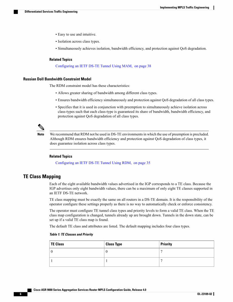
TE Class MappingEach of the eight available bandwidth values advertised in the IGP corresponds to a TE class. Because theIGP advertises only eight bandwidth values, there can be a maximum of only eight TE classes supported inan IETF DS-TE network.
TE class mapping must be exactly the same on all routers in a DS-TE domain. It is the responsibility of theoperator configure these settings properly as there is no way to automatically check or enforce consistency.
The operator must configure TE tunnel class types and priority levels to form a valid TE class. When the TEclass map configuration is changed, tunnels already up are brought down. Tunnels in the down state, can beset up if a valid TE class map is found.
The default TE class and attributes are listed. The default mapping includes four class types.
Table 1: TE Classes and Priority
PriorityClass TypeTE Class
700
711
Cisco ASR 9000 Series Aggregation Services Router MPLS Configuration Guide, Release 4.06 OL-23109-02
Implementing MPLS Traffic EngineeringDifferentiated Services Traffic Engineering
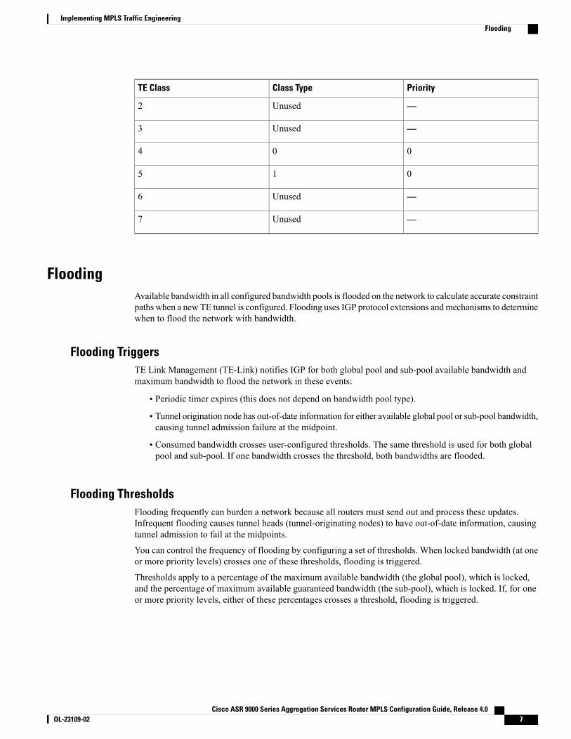
PriorityClass TypeTE Class
—Unused2
—Unused3
004
015
—Unused6
—Unused7
FloodingAvailable bandwidth in all configured bandwidth pools is flooded on the network to calculate accurate constraintpaths when a newTE tunnel is configured. Flooding uses IGP protocol extensions andmechanisms to determinewhen to flood the network with bandwidth.
Flooding TriggersTE Link Management (TE-Link) notifies IGP for both global pool and sub-pool available bandwidth andmaximum bandwidth to flood the network in these events:
• Periodic timer expires (this does not depend on bandwidth pool type).
• Tunnel origination node has out-of-date information for either available global pool or sub-pool bandwidth,causing tunnel admission failure at the midpoint.
• Consumed bandwidth crosses user-configured thresholds. The same threshold is used for both globalpool and sub-pool. If one bandwidth crosses the threshold, both bandwidths are flooded.
Flooding ThresholdsFlooding frequently can burden a network because all routers must send out and process these updates.Infrequent flooding causes tunnel heads (tunnel-originating nodes) to have out-of-date information, causingtunnel admission to fail at the midpoints.
You can control the frequency of flooding by configuring a set of thresholds. When locked bandwidth (at oneor more priority levels) crosses one of these thresholds, flooding is triggered.
Thresholds apply to a percentage of the maximum available bandwidth (the global pool), which is locked,and the percentage of maximum available guaranteed bandwidth (the sub-pool), which is locked. If, for oneor more priority levels, either of these percentages crosses a threshold, flooding is triggered.
Cisco ASR 9000 Series Aggregation Services Router MPLS Configuration Guide, Release 4.0 OL-23109-02 7
Implementing MPLS Traffic EngineeringFlooding
Setting up a global pool TE tunnel can cause the locked bandwidth allocated to sub-pool tunnels to bereduced (and hence to cross a threshold). A sub-pool TE tunnel setup can similarly cause the lockedbandwidth for global pool TE tunnels to cross a threshold. Thus, sub-pool TE and global pool TE tunnelscan affect each other when flooding is triggered by thresholds.
Note
Fast RerouteFast Reroute (FRR) provides link protection to LSPs enabling the traffic carried by LSPs that encounter afailed link to be rerouted around the failure. The reroute decision is controlled locally by the router connectedto the failed link. The headend router on the tunnel is notified of the link failure through IGP or through RSVP.When it is notified of a link failure, the headend router attempts to establish a new LSP that bypasses thefailure. This provides a path to reestablish links that fail, providing protection to data transfer.
FRR (link or node) is supported over sub-pool tunnels the same way as for regular TE tunnels. In particular,when link protection is activated for a given link, TE tunnels eligible for FRR are redirected into the protectionLSP, regardless of whether they are sub-pool or global pool tunnels.
The ability to configure FRR on a per-LSP basis makes it possible to provide different levels of fastrestoration to tunnels from different bandwidth pools.
Note
You should be aware of these requirements for the backup tunnel path:
• Backup tunnel must not pass through the element it protects.
• Primary tunnel and a backup tunnel should intersect at least at two points (nodes) on the path: point oflocal repair (PLR) and merge point (MP). PLR is the headend of the backup tunnel, andMP is the tailendof the backup tunnel.
When you configure TE tunnel with multiple protection on its path and merge point is the same node formore than one protection, you must configure record-route for that tunnel.
Note
Related Topics
Protecting MPLS Tunnels with Fast Reroute, on page 28
MPLS-TE and Fast Reroute over Link BundlesMPLS Traffic Engineering (TE) and Fast Reroute (FRR) are supported over bundle interfaces and virtuallocal area network (VLAN) interfaces. Bidirectional forwarding detection (BFD) over VLAN is used as anFRR trigger to obtain less than 50 milliseconds of switchover time.
These link bundle types are supported for MPLS-TE/FRR:
• Over Ethernet link bundles.
• Over VLANs over Ethernet link bundles.
Cisco ASR 9000 Series Aggregation Services Router MPLS Configuration Guide, Release 4.08 OL-23109-02
Implementing MPLS Traffic EngineeringFast Reroute
• Number of links are limited to 100 for MPLS-TE and FRR.
• VLANs go over any Ethernet interface (for example, GigabitEthernet and TenGigE).
FRR is supported over bundle interfaces in the following ways:
• Uses minimum links as a threshold to trigger FRR over a bundle interface.
• Uses the minimum total available bandwidth as a threshold to trigger FRR.
Ignore Intermediate System-to-Intermediate System Overload Bit Setting inMPLS-TE
The Ignore Intermediate System-to-Intermediate System (IS-IS) Overload Bit Setting in MPLS-TE featureensures that the RSVP-TE LSPs are not broken because of routers that enabled the IS-IS overload bit.
The current implementation does not allow nodes that have indicated an overload situation through theIS-IS overload bit.
Note
Therefore, an overloaded node cannot be used. The IS-IS overload bit limitation is an indication of an overloadsituation in the IP topology. The feature provides a method to prevent an IS-IS overload condition fromaffecting MPLS-TE.
Enhancement Options of IS-IS OLA
Related Topics
Configuring the Ignore Integrated IS-IS Overload Bit Setting in MPLS-TE, on page 44Configure the Ignore IS-IS Overload Bit Setting in MPLS-TE: Example, on page 77
Flexible Name-based Tunnel ConstraintsMPLS-TE Flexible Name-based Tunnel Constraints provides a simplified and more flexible means ofconfiguring link attributes and path affinities to compute paths for MPLS-TE tunnels.
In the traditional TE scheme, links are configured with attribute-flags that are flooded with TE link-stateparameters using Interior Gateway Protocols (IGPs), such as Open Shortest Path First (OSPF).
MPLS-TE Flexible Name-based Tunnel Constraints lets you assign, or map, up to 32 color names for affinityand attribute-flag attributes instead of 32-bit hexadecimal numbers. After mappings are defined, the attributescan be referred to by the corresponding color name in the command-line interface (CLI). Furthermore, youcan define constraints using include, include-strict, exclude, and exclude-all arguments, where each statementcan contain up to 10 colors, and define include constraints in both loose and strict sense.
You can configure affinity constraints using attribute flags or the Flexible Name Based Tunnel Constraintsscheme; however, when configurations for both schemes exist, only the configuration pertaining to thenew scheme is applied.
Note
Cisco ASR 9000 Series Aggregation Services Router MPLS Configuration Guide, Release 4.0 OL-23109-02 9
Implementing MPLS Traffic EngineeringIgnore Intermediate System-to-Intermediate System Overload Bit Setting in MPLS-TE
Related Topics
Assigning Color Names to Numeric Values, on page 45Associating Affinity-Names with TE Links, on page 47Associating Affinity Constraints for TE Tunnels, on page 49Configure Flexible Name-based Tunnel Constraints: Example, on page 78
MPLS Traffic Engineering Interarea TunnelingThese topics describe the following new extensions of MPLS-TE:
• Interarea Support, on page 10
• Multiarea Support, on page 11
• Loose Hop Expansion, on page 11
• Loose Hop Reoptimization, on page 12
• Fast Reroute Node Protection, on page 12
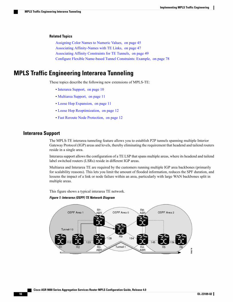
Interarea SupportThe MPLS-TE interarea tunneling feature allows you to establish P2P tunnels spanning multiple InteriorGateway Protocol (IGP) areas and levels, thereby eliminating the requirement that headend and tailend routersreside in a single area.
Interarea support allows the configuration of a TE LSP that spans multiple areas, where its headend and tailendlabel switched routers (LSRs) reside in different IGP areas.
Multiarea and Interarea TE are required by the customers running multiple IGP area backbones (primarilyfor scalability reasons). This lets you limit the amount of flooded information, reduces the SPF duration, andlessens the impact of a link or node failure within an area, particularly with large WAN backbones split inmultiple areas.
This figure shows a typical interarea TE network.Figure 1: Interarea (OSPF) TE Network Diagram
Cisco ASR 9000 Series Aggregation Services Router MPLS Configuration Guide, Release 4.010 OL-23109-02
Implementing MPLS Traffic EngineeringMPLS Traffic Engineering Interarea Tunneling
Multiarea SupportMultiarea support allows an area border router (ABR) LSR to support MPLS-TE in more than one IGP area.A TE LSP is still confined to a single area.
Multiarea and Interarea TE are required when you run multiple IGP area backbones. The Multiarea andInterarea TE allows you to:
• Limit the volume of flooded information.
• Reduce the SPF duration.
• Decrease the impact of a link or node failure within an area.
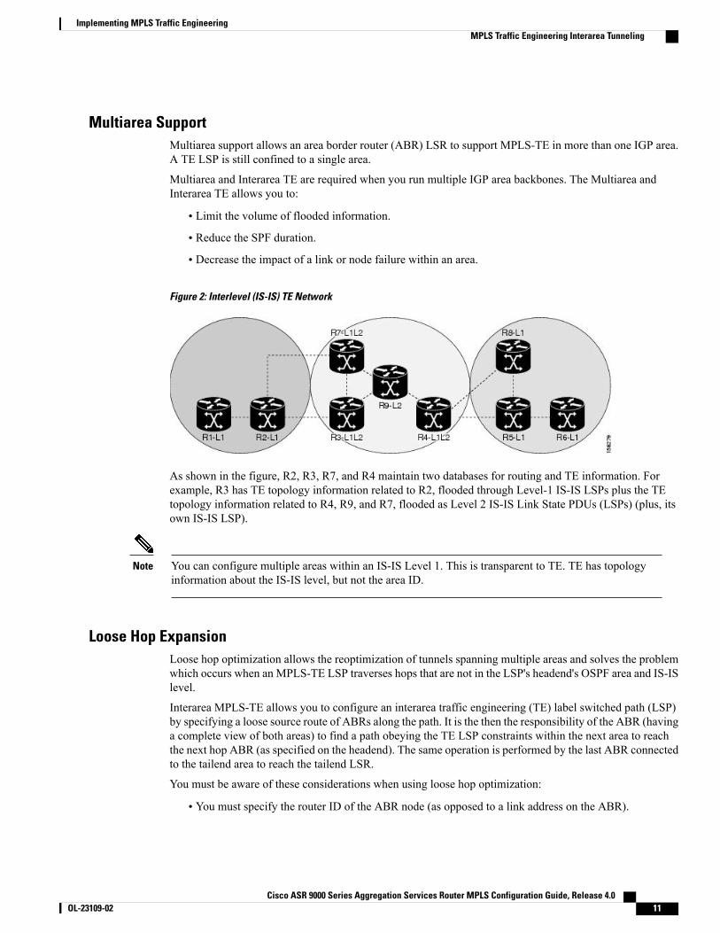
Figure 2: Interlevel (IS-IS) TE Network
As shown in the figure, R2, R3, R7, and R4 maintain two databases for routing and TE information. Forexample, R3 has TE topology information related to R2, flooded through Level-1 IS-IS LSPs plus the TEtopology information related to R4, R9, and R7, flooded as Level 2 IS-IS Link State PDUs (LSPs) (plus, itsown IS-IS LSP).
You can configure multiple areas within an IS-IS Level 1. This is transparent to TE. TE has topologyinformation about the IS-IS level, but not the area ID.
Note
Loose Hop ExpansionLoose hop optimization allows the reoptimization of tunnels spanning multiple areas and solves the problemwhich occurs when an MPLS-TE LSP traverses hops that are not in the LSP's headend's OSPF area and IS-ISlevel.
Interarea MPLS-TE allows you to configure an interarea traffic engineering (TE) label switched path (LSP)by specifying a loose source route of ABRs along the path. It is the then the responsibility of the ABR (havinga complete view of both areas) to find a path obeying the TE LSP constraints within the next area to reachthe next hop ABR (as specified on the headend). The same operation is performed by the last ABR connectedto the tailend area to reach the tailend LSR.
You must be aware of these considerations when using loose hop optimization:
• You must specify the router ID of the ABR node (as opposed to a link address on the ABR).
Cisco ASR 9000 Series Aggregation Services Router MPLS Configuration Guide, Release 4.0 OL-23109-02 11
Implementing MPLS Traffic EngineeringMPLS Traffic Engineering Interarea Tunneling
•When multiarea is deployed in a network that contains subareas, you must enable MPLS-TE in thesubarea for TE to find a path when loose hop is specified.
• You must specify the reachable explicit path for the interarea tunnel.
Loose Hop ReoptimizationLoose hop reoptimization allows the reoptimization of the tunnels spanning multiple areas and solves theproblem which occurs when an MPLS-TE headend does not have visibility into other IGP areas.
Whenever the headend attempts to reoptimize a tunnel, it tries to find a better path to the ABR in the headendarea. If a better path is found then the headend initiates the setup of a new LSP. In case a suitable path is notfound in the headend area, the headend initiates a querying message. The purpose of this message is to querythe ABRs in the areas other than the headend area to check if there exist any better paths in those areas. Thepurpose of this message is to query the ABRs in the areas other than the headend area, to check if a betterpath exists. If a better path does not exist, ABR forwards the query to the next router downstream. Alternatively,if better path is found, ABR responds with a special Path Error to the headend to indicate the existence of abetter path outside the headend area. Upon receiving the Path Error that indicates the existence of a betterpath, the headend router initiates the reoptimization.
ABR Node ProtectionBecause one IGP area does not have visibility into another IGP area, it is not possible to assign backup toprotect ABR node. To overcome this problem, node ID sub-object is added into the record route object of theprimary tunnel so that at a PLR node, backup destination address can be checked against primary tunnelrecord-route object and assign a backup tunnel.
Fast Reroute Node ProtectionIf a link failure occurs within an area, the upstream router directly connected to the failed link generates anRSVP path error message to the headend. As a response to the message, the headend sends an RSVP pathtear message and the corresponding path option is marked as invalid for a specified period and the nextpath-option (if any) is evaluated.
To retry the ABR immediately, a second path option (identical to the first one) should be configured.Alternatively, the retry period (path-option hold-down, 2 minutes by default) can be tuned to achieve a fasterretry.
Related Topics
Protecting MPLS Tunnels with Fast Reroute, on page 28
MPLS-TE Forwarding AdjacencyThe MPLS-TE Forwarding Adjacency feature allows a network administrator to handle a traffic engineering,label-switched path (LSP) tunnel as a link in an Interior Gateway Protocol (IGP) network based on the ShortestPath First (SPF) algorithm. A forwarding adjacency can be created between routers regardless of their locationin the network.
Cisco ASR 9000 Series Aggregation Services Router MPLS Configuration Guide, Release 4.012 OL-23109-02
Implementing MPLS Traffic EngineeringMPLS-TE Forwarding Adjacency
MPLS-TE Forwarding Adjacency BenefitsTE tunnel interfaces are advertised in the IGP network just like any other links. Routers can then use theseadvertisements in their IGPs to compute the SPF even if they are not the head end of any TE tunnels.
Related Topics
Configuring MPLS-TE Forwarding Adjacency, on page 56Configure Forwarding Adjacency: Example, on page 80
MPLS-TE Forwarding Adjacency RestrictionsThe following restrictions are listed for the MPLS-TE Forwarding Adjacency feature:
• Using theMPLS-TE Forwarding Adjacency feature increases the size of the IGP database by advertisinga TE tunnel as a link.
• The MPLS-TE Forwarding Adjacency feature is supported by Intermediate System-to-IntermediateSystem (IS-IS).
•When the MPLS-TE Forwarding Adjacency feature is enabled on a TE tunnel, the link is advertised inthe IGP network as a Type-Length-Value (TLV) 22 without any TE sub-TLV.
• MPLS-TE forwarding adjacency tunnels must be configured bidirectionally.
MPLS-TE Forwarding Adjacency PrerequisitesYour network must support the following features before enabling the MPLS -TE Forwarding Adjacencyfeature:
• MPLS
• IP Cisco Express Forwarding
• Intermediate System-to-Intermediate System (IS-IS)
Path Computation ElementPath Computation Element (PCE) solves the specific issue of inter-domain path computation for MPLS-TElabel switched path (LSPs), when the head-end router does not possess full network topology information(for example, when the head-end and tail-end routers of an LSP reside in different IGP areas).
PCE uses area border routers (ABRs) to compute a TE LSP spanningmultiple IGP areas as well as computationof Inter-AS TE LSP.
PCE is usually used to define an overall architecture, which is made of several components, as follows:
Path Computation Element (PCE)
Represents a software module (which can be a component or application) that enables the router tocompute paths applying a set of constraints between any pair of nodes within the router’s TE topologydatabase. PCEs are discovered through IGP.
Cisco ASR 9000 Series Aggregation Services Router MPLS Configuration Guide, Release 4.0 OL-23109-02 13
Implementing MPLS Traffic EngineeringPath Computation Element
Path Computation Client (PCC)
Represents a software module running on a router that is capable of sending and receiving pathcomputation requests and responses to and from PCEs. The PCC is typically an LSR (Label SwitchingRouter).
PCC-PCE communication protocol (PCEP)
Specifies that PCEP is a TCP-based protocol defined by the IETF PCEWG, and defines a set of messagesand objects used to manage PCEP sessions and to request and send paths for multi-domain TE LSPs.PCEP is used for communication between PCC and PCE (as well as between two PCEs) and employsIGP extensions to dynamically discover PCE.
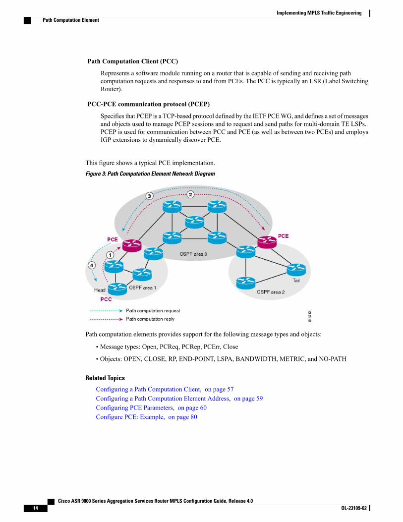
This figure shows a typical PCE implementation.Figure 3: Path Computation Element Network Diagram
Path computation elements provides support for the following message types and objects:
• Message types: Open, PCReq, PCRep, PCErr, Close
• Objects: OPEN, CLOSE, RP, END-POINT, LSPA, BANDWIDTH, METRIC, and NO-PATH
Related Topics
Configuring a Path Computation Client, on page 57Configuring a Path Computation Element Address, on page 59Configuring PCE Parameters, on page 60Configure PCE: Example, on page 80
Cisco ASR 9000 Series Aggregation Services Router MPLS Configuration Guide, Release 4.014 OL-23109-02
Implementing MPLS Traffic EngineeringPath Computation Element
Path ProtectionPath protection provides an end-to-end failure recoverymechanism (that is, a full path protection) forMPLS-TEtunnels. A secondary Label Switched Path (LSP) is established, in advance, to provide failure protection forthe protected LSP that is carrying a tunnel's TE traffic. When there is a failure on the protected LSP, the sourcerouter immediately enables the secondary LSP to temporarily carry the tunnel's traffic. If there is a failure onthe secondary LSP, the tunnel no longer has path protection until the failure along the secondary path iscleared. Path protection can be used within a single area (OSPF or IS-IS), external BGP [eBGP], and staticroutes.
The failure detection mechanisms triggers a switchover to a secondary tunnel by:
• Path error or resv-tear from Resource Reservation Protocol (RSVP) signaling
• Notification from the Bidirectional Forwarding Detection (BFD) protocol that a neighbor is lost
• Notification from the Interior Gateway Protocol (IGP) that the adjacency is down
• Local teardown of the protected tunnel's LSP due to preemption in order to signal higher priority LSPs,a Packet over SONET (POS) alarm, online insertion and removal (OIR), and so on
An alternate recovery mechanism is Fast Reroute (FRR), which protects MPLS-TE LSPs only from link andnode failures, by locally repairing the LSPs at the point of failure.
Although not as fast as link or node protection, presignaling a secondary LSP is faster than configuring asecondary primary path option, or allowing the tunnel's source router to dynamically recalculate a path. Theactual recovery time is topology-dependent, and affected by delay factors such as propagation delay or switchfabric latency.
Related Topics
Enabling Path Protection for an Interface, on page 63Assigning a Dynamic Path Option to a Tunnel, on page 65Forcing a Manual Switchover on a Path-Protected Tunnel, on page 67Configuring the Delay the Tunnel Takes Before Reoptimization, on page 67Configure Tunnels for Path Protection: Example, on page 81
Pre-requisites for Path ProtectionThese are the pre-requisites for enabling path protection:
• Ensure that your network supports MPLS-TE, Cisco Express Forwarding, and IntermediateSystem-to-Intermediate System (IS-IS) or Open Shortest Path First (OSPF).
• Enable MPLS.
• Configure TE on the routers.
• Configure a TE tunnel with a dynamic path option by using the path-option command with thedynamic keyword.
Related Topics
Enabling Path Protection for an Interface, on page 63
Cisco ASR 9000 Series Aggregation Services Router MPLS Configuration Guide, Release 4.0 OL-23109-02 15
Implementing MPLS Traffic EngineeringPath Protection
Assigning a Dynamic Path Option to a Tunnel, on page 65Forcing a Manual Switchover on a Path-Protected Tunnel, on page 67Configuring the Delay the Tunnel Takes Before Reoptimization, on page 67Configure Tunnels for Path Protection: Example, on page 81
Restrictions for Path Protection• Only Point-to-Point (P2P) tunnels are supported.
• Point-to-Multipoint (P2MP) TE tunnels are not supported.
• A maximum of one standby LSP is supported.
• There can be only one secondary path for each dynamic path option.
• Explicit path option can be configured for the path protected TE with the secondary path option asdynamic.
• Do not use link and node protection with path protection on the headend router.
• A maximum number of path protected tunnel TE heads is 2000.
• A maximum number of TE tunnel heads is equal to 4000.
Related Topics
Enabling Path Protection for an Interface, on page 63Assigning a Dynamic Path Option to a Tunnel, on page 65Forcing a Manual Switchover on a Path-Protected Tunnel, on page 67Configuring the Delay the Tunnel Takes Before Reoptimization, on page 67Configure Tunnels for Path Protection: Example, on page 81
MPLS-TE Automatic BandwidthThe MPLS-TE automatic bandwidth feature measures the traffic in a tunnel and periodically adjusts thesignaled bandwidth for the tunnel.
These topics provide information about MPLS-TE automatic bandwidth:
MPLS-TE Automatic Bandwidth OverviewMPLS-TE automatic bandwidth is configured on individual Label Switched Paths (LSPs) at every head-end.MPLS-TE monitors the traffic rate on a tunnel interface. Periodically, MPLS-TE resizes the bandwidth onthe tunnel interface to align it closely with the traffic in the tunnel. MPLS-TE automatic bandwidth can performthese functions:
• Monitors periodic polling of the tunnel output rate
• Resizes the tunnel bandwidth by adjusting the highest rate observed during a given period
For every traffic-engineered tunnel that is configured for an automatic bandwidth, the average output rate issampled, based on various configurable parameters. Then, the tunnel bandwidth is readjusted automatically
Cisco ASR 9000 Series Aggregation Services Router MPLS Configuration Guide, Release 4.016 OL-23109-02
Implementing MPLS Traffic EngineeringMPLS-TE Automatic Bandwidth
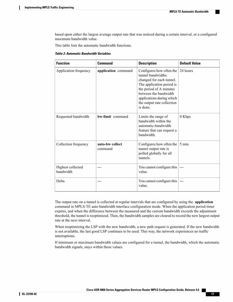
based upon either the largest average output rate that was noticed during a certain interval, or a configuredmaximum bandwidth value.
This table lists the automatic bandwidth functions.
Table 2: Automatic Bandwidth Variables
Default ValueDescriptionCommandFunction
24 hoursConfigures how often thetunnel bandwidthschanged for each tunnel.The application period isthe period of A minutesbetween the bandwidthapplications during whichthe output rate collectionis done.
application commandApplication frequency
0 KbpsLimits the range ofbandwidth within theautomatic-bandwidthfeature that can request abandwidth.
bw-limit commandRequested bandwidth
5 minConfigures how often thetunnel output rate ispolled globally for alltunnels.
auto-bw collectcommand
Collection frequency
—You cannot configure thisvalue.
—Highest collectedbandwidth
—You cannot configure thisvalue.
—Delta
The output rate on a tunnel is collected at regular intervals that are configured by using the applicationcommand in MPLS-TE auto bandwidth interface configuration mode. When the application period timerexpires, and when the difference between the measured and the current bandwidth exceeds the adjustmentthreshold, the tunnel is reoptimized. Then, the bandwidth samples are cleared to record the new largest outputrate at the next interval.
When reoptimizing the LSP with the new bandwidth, a new path request is generated. If the new bandwidthis not available, the last good LSP continues to be used. This way, the network experiences no trafficinterruptions.
If minimum or maximum bandwidth values are configured for a tunnel, the bandwidth, which the automaticbandwidth signals, stays within these values.
Cisco ASR 9000 Series Aggregation Services Router MPLS Configuration Guide, Release 4.0 OL-23109-02 17
Implementing MPLS Traffic EngineeringMPLS-TE Automatic Bandwidth
When more than 100 tunnels are auto-bw enabled, the algorithm will jitter the first application of everytunnel by a maximum of 20% (max 1hour). The algorithm does this to avoid too many tunnels runningauto bandwidth applications at the same time.
Note
If a tunnel is shut down, and is later brought again, the adjusted bandwidth is lost and the tunnel is broughtback with the initial configured bandwidth. In addition, the application period is reset when the tunnel isbrought back.
Related Topics
Configuring the Collection Frequency, on page 69Configuring the Automatic Bandwidth Functions, on page 72Configure Automatic Bandwidth: Example, on page 81
Adjustment ThresholdAdjustment Threshold is defined as a percentage of the current tunnel bandwidth and an absolute (minimum)bandwidth. Both thresholds must be fulfilled for the automatic bandwidth to resignal the tunnel. The tunnelbandwidth is resized only if the difference between the largest sample output rate and the current tunnelbandwidth is larger than the adjustment thresholds.
For example, assume that the automatic bandwidth is enabled on a tunnel in which the highest observedbandwidth B is 30 Mbps. Also, assume that the tunnel was initially configured for 45 Mbps. Therefore, thedifference is 15 mbit/s. Now, assuming the default adjustment thresholds of 10% and 10kbps, the tunnel issignalled with 30 Mbps when the application timer expires. This is because 10% of 45Mbit/s is 4.5 Mbit/s,which is smaller than 15 Mbit/s. The absolute threshold, which by default is 10kbps, is also crossed.
Overflow DetectionOverflow detection is used if a bandwidth must be resized as soon as an overflow condition is detected, withouthaving to wait for the expiry of an automatic bandwidth application frequency interval.
For overflow detection one configures a limit N, a percentage threshold Y% and optionally, a minimumbandwidth threshold Z. The percentage threshold is defined as the percentage of the actual signalled tunnelbandwidth. When the difference between the measured bandwidth and the actual bandwidth are both largerthan Y% and Z threshold, for N consecutive times, then the system triggers an overflow detection.
The bandwidth adjustment by the overflow detection is triggered only by an increase of traffic volume throughthe tunnel, and not by a decrease in the traffic volume. When you trigger an overflow detection, the automaticbandwidth application interval is reset.
By default, the overflow detection is disabled and needs to be manually configured.
Restrictions for MPLS-TE Automatic BandwidthWhen the automatic bandwidth cannot update the tunnel bandwidth, the following restrictions are listed:
• Tunnel is in a fast reroute (FRR) backup, active, or path protect active state. This occurs because of theassumption that protection is a temporary state, and there is no need to reserve the bandwidth on a backuptunnel. You should prevent taking away the bandwidth from other primary or backup tunnels.
Cisco ASR 9000 Series Aggregation Services Router MPLS Configuration Guide, Release 4.018 OL-23109-02
Implementing MPLS Traffic EngineeringMPLS-TE Automatic Bandwidth
• Reoptimization fails to occur during a lockdown. In this case, the automatic bandwidth does not updatethe bandwidth unless the bandwidth application is manually triggered by using the mpls traffic-engauto-bw apply command in EXEC mode.
How to Implement Traffic EngineeringTraffic engineering requires coordination among several global neighbor routers, creating traffic engineeringtunnels, setting up forwarding across traffic engineering tunnels, setting up FRR, and creating differentialservice.
These procedures are used to implement MPLS-TE:
Building MPLS-TE TopologyPerform this task to configure MPLS-TE topology (required for traffic engineering tunnel operations).
Before You Begin
Before you start to build the MPLS-TE topology, you must have enabled:
• IGP such as OSPF or IS-IS for MPLS-TE.
• MPLS Label Distribution Protocol (LDP).
• RSVP on the port interface.
• Stable router ID is required at either end of the link to ensure that the link is successful. If you do notassign a router ID, the system defaults to the global router ID. Default router IDs are subject to change,which can result in an unstable link.
• If you are going to use nondefault holdtime or intervals, you must decide the values to which they areset.
Cisco ASR 9000 Series Aggregation Services Router MPLS Configuration Guide, Release 4.0 OL-23109-02 19
Implementing MPLS Traffic EngineeringHow to Implement Traffic Engineering
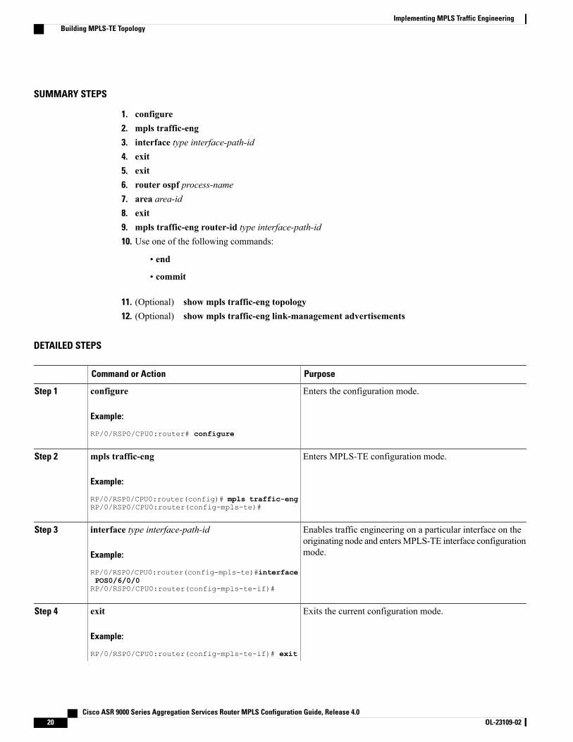
SUMMARY STEPS
1. configure2. mpls traffic-eng3. interface type interface-path-id4. exit5. exit6. router ospf process-name7. area area-id8. exit9. mpls traffic-eng router-id type interface-path-id10. Use one of the following commands:
• end
• commit
11. (Optional) show mpls traffic-eng topology12. (Optional) show mpls traffic-eng link-management advertisements
DETAILED STEPS
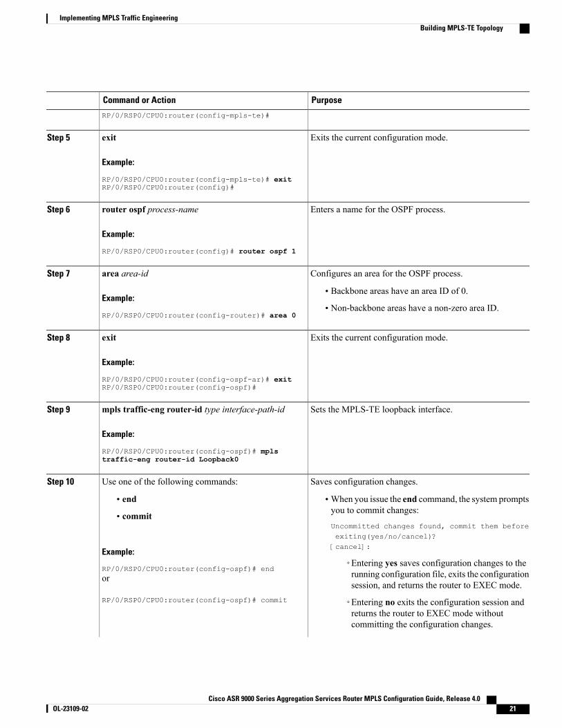
PurposeCommand or Action
Enters the configuration mode.configure
Example:
RP/0/RSP0/CPU0:router# configure
Step 1
Enters MPLS-TE configuration mode.mpls traffic-eng
Example:
RP/0/RSP0/CPU0:router(config)# mpls traffic-eng
Step 2
RP/0/RSP0/CPU0:router(config-mpls-te)#
Enables traffic engineering on a particular interface on theoriginating node and entersMPLS-TE interface configurationmode.
interface type interface-path-id
Example:
RP/0/RSP0/CPU0:router(config-mpls-te)#interface
Step 3
POS0/6/0/0RP/0/RSP0/CPU0:router(config-mpls-te-if)#
Exits the current configuration mode.exit
Example:
RP/0/RSP0/CPU0:router(config-mpls-te-if)# exit
Step 4
Cisco ASR 9000 Series Aggregation Services Router MPLS Configuration Guide, Release 4.020 OL-23109-02
Implementing MPLS Traffic EngineeringBuilding MPLS-TE Topology
PurposeCommand or Action
RP/0/RSP0/CPU0:router(config-mpls-te)#
Exits the current configuration mode.exit
Example:
RP/0/RSP0/CPU0:router(config-mpls-te)# exit
Step 5
RP/0/RSP0/CPU0:router(config)#
Enters a name for the OSPF process.router ospf process-name
Example:
RP/0/RSP0/CPU0:router(config)# router ospf 1
Step 6
Configures an area for the OSPF process.area area-idStep 7
Example:
RP/0/RSP0/CPU0:router(config-router)# area 0
• Backbone areas have an area ID of 0.
• Non-backbone areas have a non-zero area ID.
Exits the current configuration mode.exit
Example:
RP/0/RSP0/CPU0:router(config-ospf-ar)# exit
Step 8
RP/0/RSP0/CPU0:router(config-ospf)#
Sets the MPLS-TE loopback interface.mpls traffic-eng router-id type interface-path-id
Example:
RP/0/RSP0/CPU0:router(config-ospf)# mpls
Step 9
traffic-eng router-id Loopback0
Saves configuration changes.Use one of the following commands:Step 10
• end •When you issue the end command, the system promptsyou to commit changes:
Uncommitted changes found, commit them beforeexiting(yes/no/cancel)?[cancel]:
• commit
Example:
RP/0/RSP0/CPU0:router(config-ospf)# end◦Entering yes saves configuration changes to therunning configuration file, exits the configurationsession, and returns the router to EXEC mode.
or
RP/0/RSP0/CPU0:router(config-ospf)# commit ◦Entering no exits the configuration session andreturns the router to EXEC mode withoutcommitting the configuration changes.
Cisco ASR 9000 Series Aggregation Services Router MPLS Configuration Guide, Release 4.0 OL-23109-02 21
Implementing MPLS Traffic EngineeringBuilding MPLS-TE Topology
PurposeCommand or Action
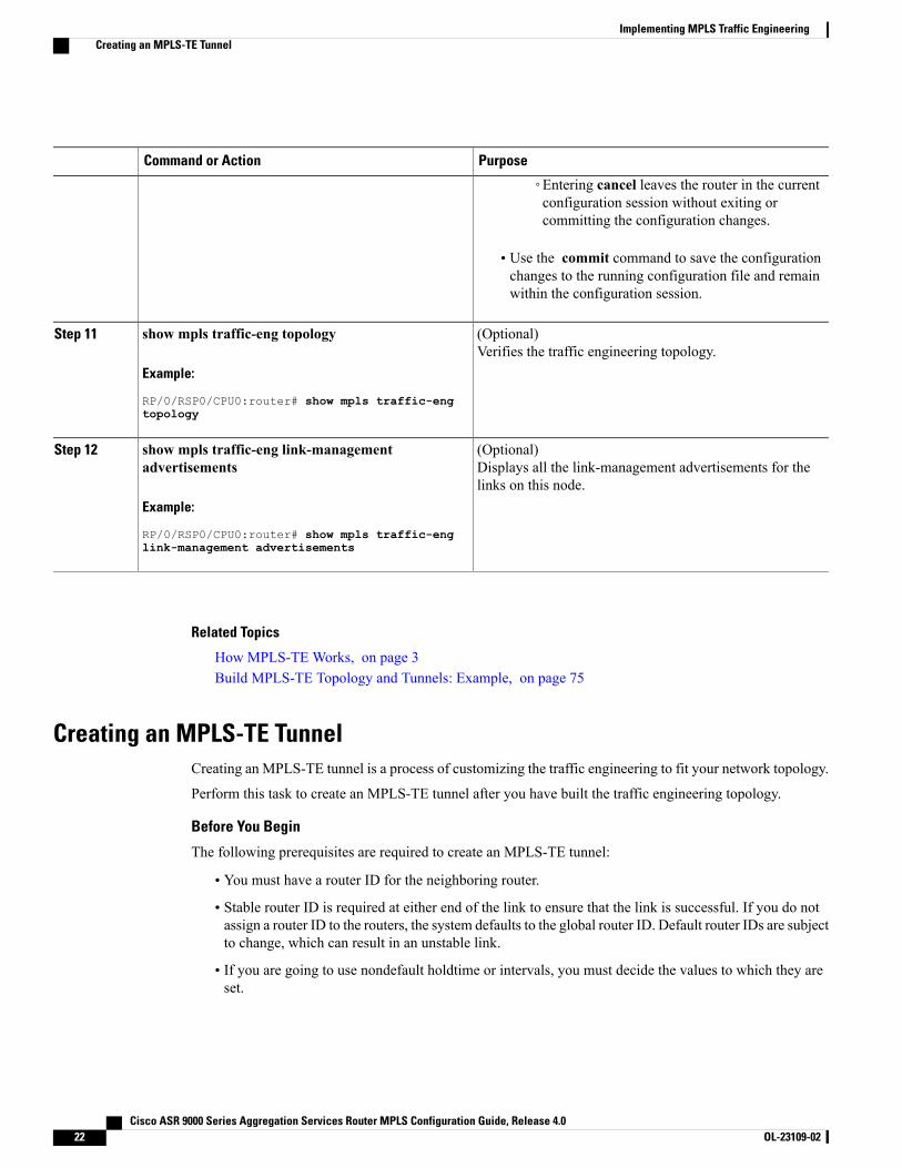
◦Entering cancel leaves the router in the currentconfiguration session without exiting orcommitting the configuration changes.
• Use the commit command to save the configurationchanges to the running configuration file and remainwithin the configuration session.
(Optional)Verifies the traffic engineering topology.
show mpls traffic-eng topology
Example:
RP/0/RSP0/CPU0:router# show mpls traffic-eng
Step 11
topology
(Optional)Displays all the link-management advertisements for thelinks on this node.
show mpls traffic-eng link-managementadvertisements
Example:
RP/0/RSP0/CPU0:router# show mpls traffic-eng
Step 12
link-management advertisements
Related Topics
How MPLS-TE Works, on page 3Build MPLS-TE Topology and Tunnels: Example, on page 75
Creating an MPLS-TE TunnelCreating an MPLS-TE tunnel is a process of customizing the traffic engineering to fit your network topology.
Perform this task to create an MPLS-TE tunnel after you have built the traffic engineering topology.
Before You Begin
The following prerequisites are required to create an MPLS-TE tunnel:
• You must have a router ID for the neighboring router.
• Stable router ID is required at either end of the link to ensure that the link is successful. If you do notassign a router ID to the routers, the system defaults to the global router ID. Default router IDs are subjectto change, which can result in an unstable link.
• If you are going to use nondefault holdtime or intervals, you must decide the values to which they areset.
Cisco ASR 9000 Series Aggregation Services Router MPLS Configuration Guide, Release 4.022 OL-23109-02
Implementing MPLS Traffic EngineeringCreating an MPLS-TE Tunnel
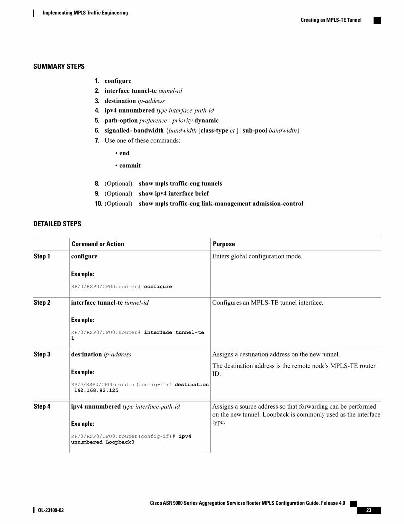
SUMMARY STEPS
1. configure2. interface tunnel-te tunnel-id3. destination ip-address4. ipv4 unnumbered type interface-path-id5. path-option preference - priority dynamic6. signalled- bandwidth {bandwidth [class-type ct ] | sub-pool bandwidth}7. Use one of these commands:
• end
• commit
8. (Optional) show mpls traffic-eng tunnels9. (Optional) show ipv4 interface brief10. (Optional) show mpls traffic-eng link-management admission-control
DETAILED STEPS
PurposeCommand or Action
Enters global configuration mode.configure
Example:
RP/0/RSP0/CPU0:router# configure
Step 1
Configures an MPLS-TE tunnel interface.interface tunnel-te tunnel-id
Example:
RP/0/RSP0/CPU0:router# interface tunnel-te
Step 2
1
Assigns a destination address on the new tunnel.destination ip-addressStep 3
Example:
RP/0/RSP0/CPU0:router(config-if)# destination
The destination address is the remote node’s MPLS-TE routerID.
192.168.92.125
Assigns a source address so that forwarding can be performedon the new tunnel. Loopback is commonly used as the interfacetype.
ipv4 unnumbered type interface-path-id
Example:
RP/0/RSP0/CPU0:router(config-if)# ipv4
Step 4
unnumbered Loopback0
Cisco ASR 9000 Series Aggregation Services Router MPLS Configuration Guide, Release 4.0 OL-23109-02 23
Implementing MPLS Traffic EngineeringCreating an MPLS-TE Tunnel
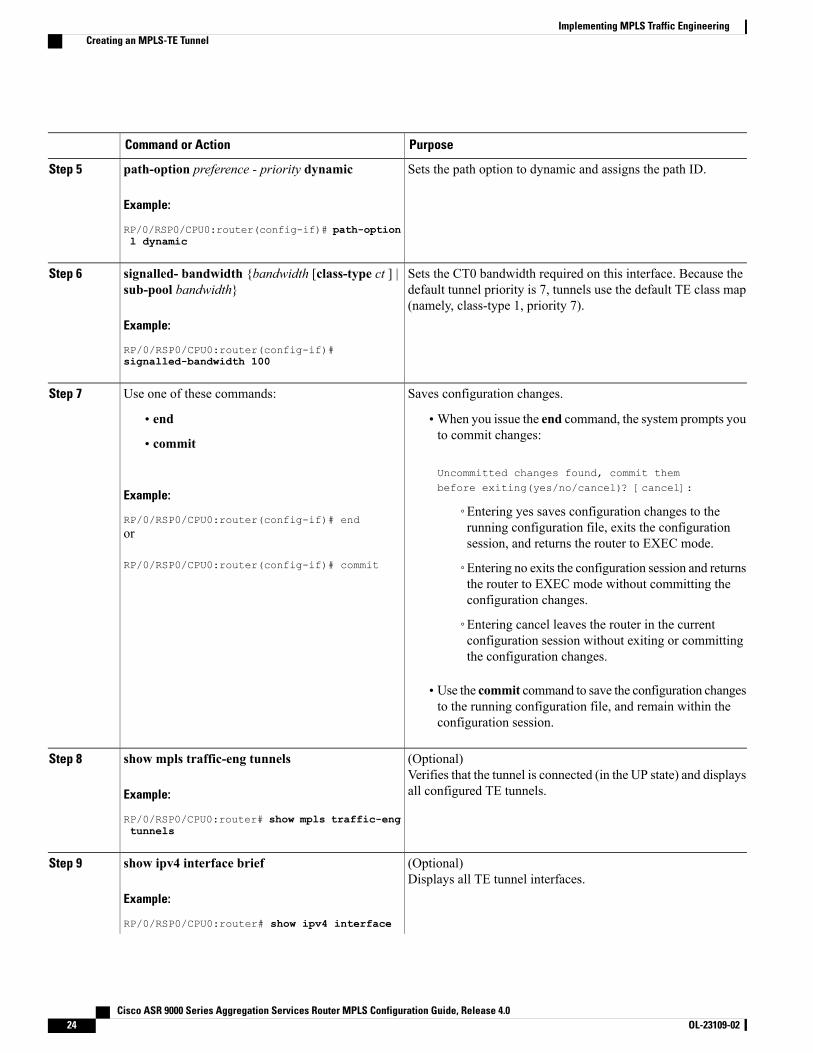
PurposeCommand or Action
Sets the path option to dynamic and assigns the path ID.path-option preference - priority dynamic
Example:
RP/0/RSP0/CPU0:router(config-if)# path-option
Step 5
l dynamic
Sets the CT0 bandwidth required on this interface. Because thedefault tunnel priority is 7, tunnels use the default TE class map(namely, class-type 1, priority 7).
signalled- bandwidth {bandwidth [class-type ct ] |sub-pool bandwidth}
Example:
RP/0/RSP0/CPU0:router(config-if)#
Step 6
signalled-bandwidth 100
Saves configuration changes.Use one of these commands:Step 7
• end •When you issue the end command, the system prompts youto commit changes:
Uncommitted changes found, commit thembefore exiting(yes/no/cancel)? [cancel]:
• commit
Example:
RP/0/RSP0/CPU0:router(config-if)# end◦Entering yes saves configuration changes to therunning configuration file, exits the configurationsession, and returns the router to EXEC mode.
or
RP/0/RSP0/CPU0:router(config-if)# commit ◦Entering no exits the configuration session and returnsthe router to EXEC mode without committing theconfiguration changes.
◦Entering cancel leaves the router in the currentconfiguration session without exiting or committingthe configuration changes.
• Use the commit command to save the configuration changesto the running configuration file, and remain within theconfiguration session.
(Optional)Verifies that the tunnel is connected (in the UP state) and displaysall configured TE tunnels.
show mpls traffic-eng tunnels
Example:
RP/0/RSP0/CPU0:router# show mpls traffic-eng
Step 8
tunnels
(Optional)Displays all TE tunnel interfaces.
show ipv4 interface brief
Example:
RP/0/RSP0/CPU0:router# show ipv4 interface
Step 9
Cisco ASR 9000 Series Aggregation Services Router MPLS Configuration Guide, Release 4.024 OL-23109-02
Implementing MPLS Traffic EngineeringCreating an MPLS-TE Tunnel
PurposeCommand or Action
brief
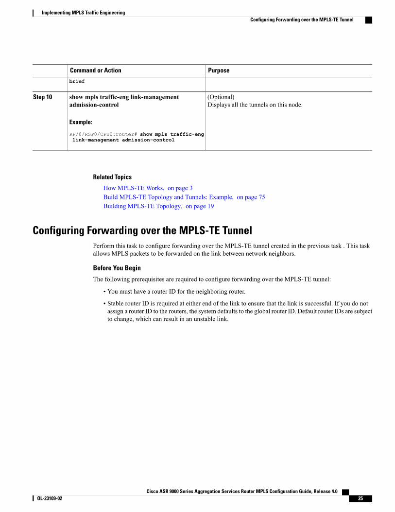
(Optional)Displays all the tunnels on this node.
show mpls traffic-eng link-managementadmission-control
Example:
RP/0/RSP0/CPU0:router# show mpls traffic-eng
Step 10
link-management admission-control
Related Topics
How MPLS-TE Works, on page 3Build MPLS-TE Topology and Tunnels: Example, on page 75Building MPLS-TE Topology, on page 19
Configuring Forwarding over the MPLS-TE TunnelPerform this task to configure forwarding over the MPLS-TE tunnel created in the previous task . This taskallows MPLS packets to be forwarded on the link between network neighbors.
Before You Begin
The following prerequisites are required to configure forwarding over the MPLS-TE tunnel:
• You must have a router ID for the neighboring router.
• Stable router ID is required at either end of the link to ensure that the link is successful. If you do notassign a router ID to the routers, the system defaults to the global router ID. Default router IDs are subjectto change, which can result in an unstable link.
Cisco ASR 9000 Series Aggregation Services Router MPLS Configuration Guide, Release 4.0 OL-23109-02 25
Implementing MPLS Traffic EngineeringConfiguring Forwarding over the MPLS-TE Tunnel
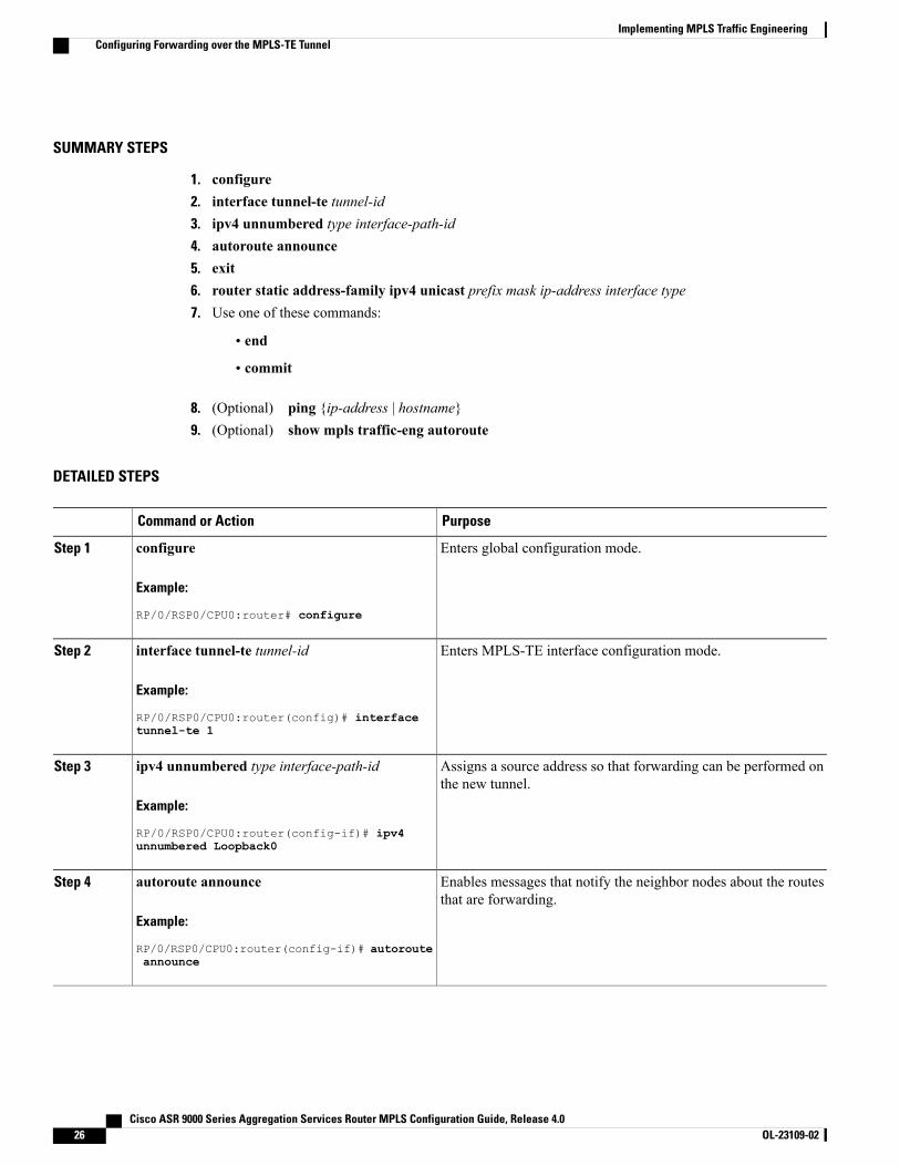
SUMMARY STEPS
1. configure2. interface tunnel-te tunnel-id3. ipv4 unnumbered type interface-path-id4. autoroute announce5. exit6. router static address-family ipv4 unicast prefix mask ip-address interface type7. Use one of these commands:
• end
• commit
8. (Optional) ping {ip-address | hostname}9. (Optional) show mpls traffic-eng autoroute
DETAILED STEPS
PurposeCommand or Action
Enters global configuration mode.configure
Example:
RP/0/RSP0/CPU0:router# configure
Step 1
Enters MPLS-TE interface configuration mode.interface tunnel-te tunnel-id
Example:
RP/0/RSP0/CPU0:router(config)# interface
Step 2
tunnel-te 1
Assigns a source address so that forwarding can be performed onthe new tunnel.
ipv4 unnumbered type interface-path-id
Example:
RP/0/RSP0/CPU0:router(config-if)# ipv4
Step 3
unnumbered Loopback0
Enables messages that notify the neighbor nodes about the routesthat are forwarding.
autoroute announce
Example:
RP/0/RSP0/CPU0:router(config-if)# autoroute
Step 4
announce
Cisco ASR 9000 Series Aggregation Services Router MPLS Configuration Guide, Release 4.026 OL-23109-02
Implementing MPLS Traffic EngineeringConfiguring Forwarding over the MPLS-TE Tunnel
PurposeCommand or Action
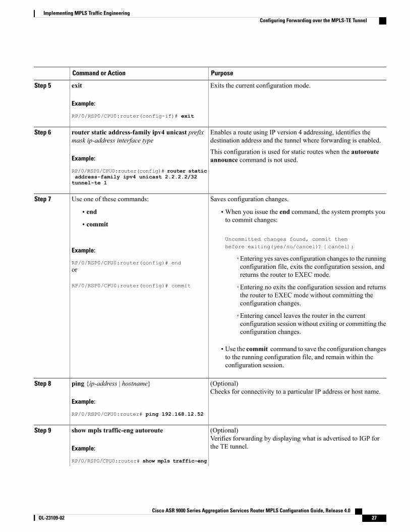
Exits the current configuration mode.exit
Example:
RP/0/RSP0/CPU0:router(config-if)# exit
Step 5
Enables a route using IP version 4 addressing, identifies thedestination address and the tunnel where forwarding is enabled.
router static address-family ipv4 unicast prefixmask ip-address interface type
Step 6
Example:
RP/0/RSP0/CPU0:router(config)# router static
This configuration is used for static routes when the autorouteannounce command is not used.
address-family ipv4 unicast 2.2.2.2/32tunnel-te 1
Saves configuration changes.Use one of these commands:Step 7
• end •When you issue the end command, the system prompts youto commit changes:
Uncommitted changes found, commit thembefore exiting(yes/no/cancel)? [cancel]:
• commit
Example:
RP/0/RSP0/CPU0:router(config)# end◦Entering yes saves configuration changes to the runningconfiguration file, exits the configuration session, andreturns the router to EXEC mode.
or
RP/0/RSP0/CPU0:router(config)# commit ◦Entering no exits the configuration session and returnsthe router to EXEC mode without committing theconfiguration changes.
◦Entering cancel leaves the router in the currentconfiguration session without exiting or committing theconfiguration changes.
• Use the commit command to save the configuration changesto the running configuration file, and remain within theconfiguration session.
(Optional)Checks for connectivity to a particular IP address or host name.
ping {ip-address | hostname}
Example:
RP/0/RSP0/CPU0:router# ping 192.168.12.52
Step 8
(Optional)Verifies forwarding by displaying what is advertised to IGP forthe TE tunnel.
show mpls traffic-eng autoroute
Example:
RP/0/RSP0/CPU0:router# show mpls traffic-eng
Step 9
Cisco ASR 9000 Series Aggregation Services Router MPLS Configuration Guide, Release 4.0 OL-23109-02 27
Implementing MPLS Traffic EngineeringConfiguring Forwarding over the MPLS-TE Tunnel
PurposeCommand or Action
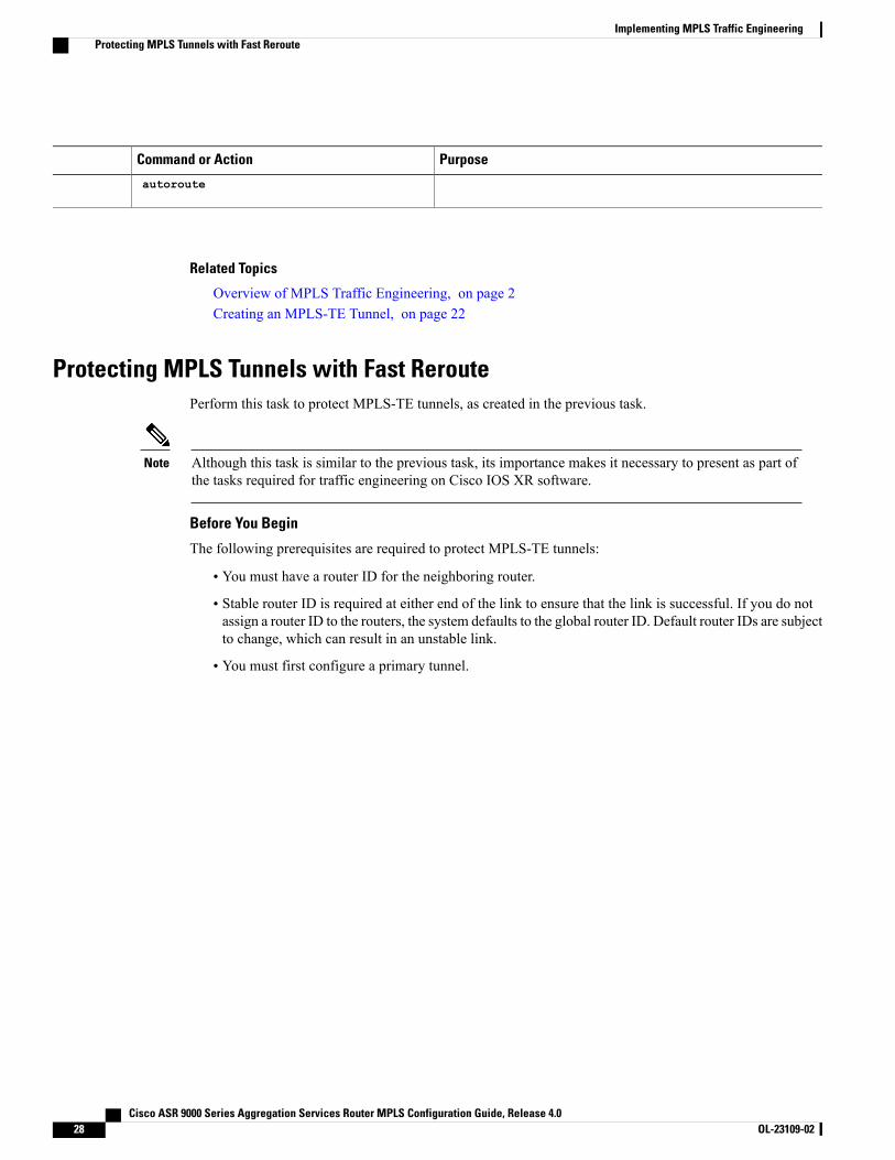
autoroute
Related Topics
Overview of MPLS Traffic Engineering, on page 2Creating an MPLS-TE Tunnel, on page 22
Protecting MPLS Tunnels with Fast ReroutePerform this task to protect MPLS-TE tunnels, as created in the previous task.
Although this task is similar to the previous task, its importance makes it necessary to present as part ofthe tasks required for traffic engineering on Cisco IOS XR software.
Note
Before You Begin
The following prerequisites are required to protect MPLS-TE tunnels:
• You must have a router ID for the neighboring router.
• Stable router ID is required at either end of the link to ensure that the link is successful. If you do notassign a router ID to the routers, the system defaults to the global router ID. Default router IDs are subjectto change, which can result in an unstable link.
• You must first configure a primary tunnel.
Cisco ASR 9000 Series Aggregation Services Router MPLS Configuration Guide, Release 4.028 OL-23109-02
Implementing MPLS Traffic EngineeringProtecting MPLS Tunnels with Fast Reroute
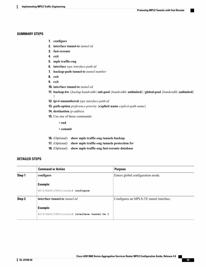
SUMMARY STEPS
1. configure2. interface tunnel-te tunnel-id3. fast-reroute4. exit5. mpls traffic-eng6. interface type interface-path-id7. backup-path tunnel-te tunnel-number8. exit9. exit10. interface tunnel-te tunnel-id11. backup-bw {backup bandwidth | sub-pool {bandwidth | unlimited} | global-pool {bandwidth | unlimited}
}12. ipv4 unnumbered type interface-path-id13. path-option preference-priority {explicit name explicit-path-name}14. destination ip-address15. Use one of these commands:
• end
• commit
16. (Optional) show mpls traffic-eng tunnels backup17. (Optional) show mpls traffic-eng tunnels protection frr18. (Optional) show mpls traffic-eng fast-reroute database
DETAILED STEPS
PurposeCommand or Action
Enters global configuration mode.configure
Example:
RP/0/RSP0/CPU0:router# configure
Step 1
Configures an MPLS-TE tunnel interface.interface tunnel-te tunnel-id
Example:
RP/0/RSP0/CPU0:router# interface tunnel-te 1
Step 2
Cisco ASR 9000 Series Aggregation Services Router MPLS Configuration Guide, Release 4.0 OL-23109-02 29
Implementing MPLS Traffic EngineeringProtecting MPLS Tunnels with Fast Reroute
PurposeCommand or Action
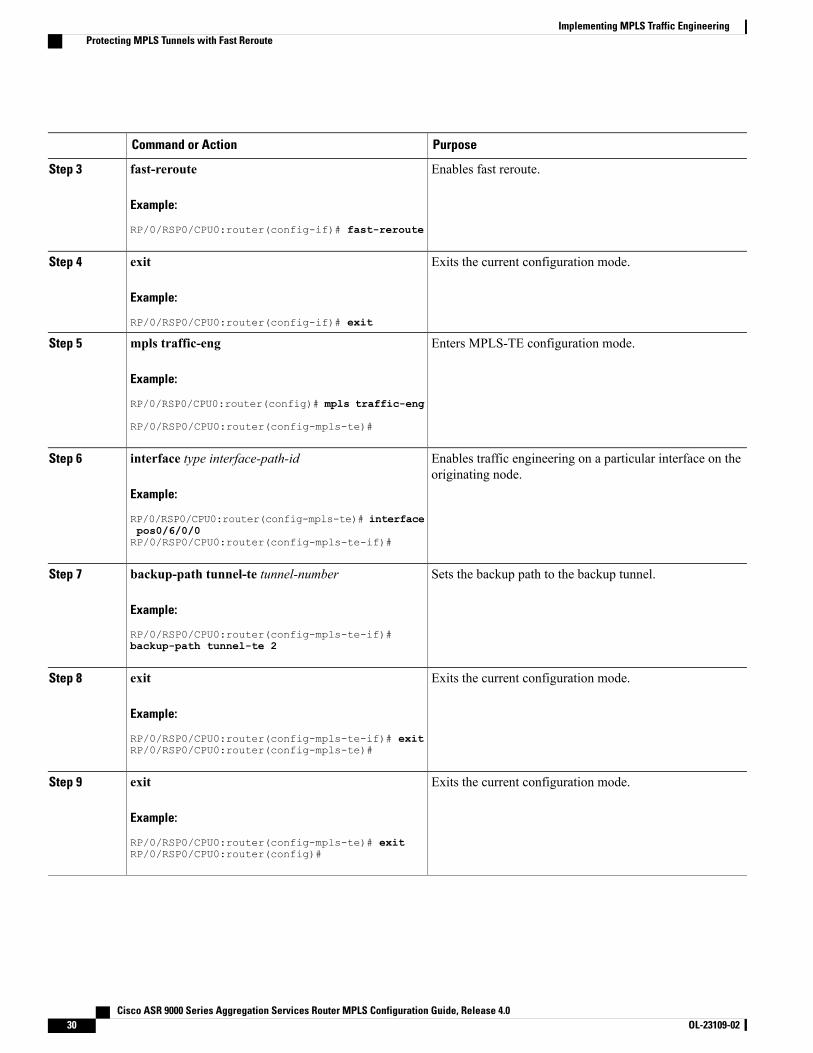
Enables fast reroute.fast-reroute
Example:
RP/0/RSP0/CPU0:router(config-if)# fast-reroute
Step 3
Exits the current configuration mode.exit
Example:
RP/0/RSP0/CPU0:router(config-if)# exit
Step 4
Enters MPLS-TE configuration mode.mpls traffic-eng
Example:
RP/0/RSP0/CPU0:router(config)# mpls traffic-eng
Step 5
RP/0/RSP0/CPU0:router(config-mpls-te)#
Enables traffic engineering on a particular interface on theoriginating node.
interface type interface-path-id
Example:
RP/0/RSP0/CPU0:router(config-mpls-te)# interface
Step 6
pos0/6/0/0RP/0/RSP0/CPU0:router(config-mpls-te-if)#
Sets the backup path to the backup tunnel.backup-path tunnel-te tunnel-number
Example:
RP/0/RSP0/CPU0:router(config-mpls-te-if)#
Step 7
backup-path tunnel-te 2
Exits the current configuration mode.exit
Example:
RP/0/RSP0/CPU0:router(config-mpls-te-if)# exit
Step 8
RP/0/RSP0/CPU0:router(config-mpls-te)#
Exits the current configuration mode.exit
Example:
RP/0/RSP0/CPU0:router(config-mpls-te)# exit
Step 9
RP/0/RSP0/CPU0:router(config)#
Cisco ASR 9000 Series Aggregation Services Router MPLS Configuration Guide, Release 4.030 OL-23109-02
Implementing MPLS Traffic EngineeringProtecting MPLS Tunnels with Fast Reroute
PurposeCommand or Action
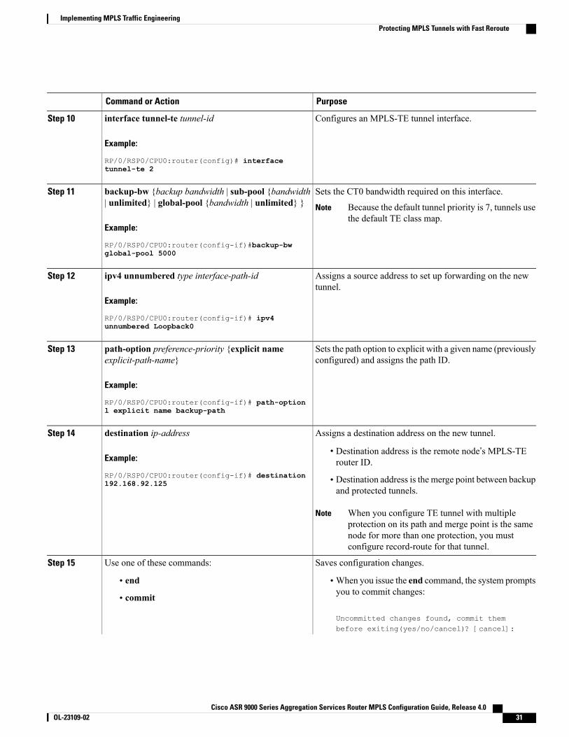
Configures an MPLS-TE tunnel interface.interface tunnel-te tunnel-id
Example:
RP/0/RSP0/CPU0:router(config)# interface
Step 10
tunnel-te 2
Sets the CT0 bandwidth required on this interface.backup-bw {backup bandwidth | sub-pool {bandwidth| unlimited} | global-pool {bandwidth | unlimited} }
Step 11
Because the default tunnel priority is 7, tunnels usethe default TE class map.
Note
Example:
RP/0/RSP0/CPU0:router(config-if)#backup-bwglobal-pool 5000
Assigns a source address to set up forwarding on the newtunnel.
ipv4 unnumbered type interface-path-id
Example:
RP/0/RSP0/CPU0:router(config-if)# ipv4
Step 12
unnumbered Loopback0
Sets the path option to explicit with a given name (previouslyconfigured) and assigns the path ID.
path-option preference-priority {explicit nameexplicit-path-name}
Example:
RP/0/RSP0/CPU0:router(config-if)# path-option
Step 13
l explicit name backup-path
Assigns a destination address on the new tunnel.destination ip-addressStep 14
Example:
RP/0/RSP0/CPU0:router(config-if)# destination
• Destination address is the remote node’s MPLS-TErouter ID.
• Destination address is the merge point between backupand protected tunnels.
192.168.92.125
When you configure TE tunnel with multipleprotection on its path and merge point is the samenode for more than one protection, you mustconfigure record-route for that tunnel.
Note
Saves configuration changes.Use one of these commands:Step 15
• end •When you issue the end command, the system promptsyou to commit changes:
Uncommitted changes found, commit thembefore exiting(yes/no/cancel)? [cancel]:
• commit
Cisco ASR 9000 Series Aggregation Services Router MPLS Configuration Guide, Release 4.0 OL-23109-02 31
Implementing MPLS Traffic EngineeringProtecting MPLS Tunnels with Fast Reroute
PurposeCommand or Action
Example:
RP/0/RSP0/CPU0:router(config-if)# end
◦Entering yes saves configuration changes to therunning configuration file, exits the configurationsession, and returns the router to EXEC mode.
◦Entering no exits the configuration session andreturns the router to EXEC mode withoutcommitting the configuration changes.
or
RP/0/RSP0/CPU0:router(config-if)# commit
◦Entering cancel leaves the router in the currentconfiguration session without exiting orcommitting the configuration changes.
• Use the commit command to save the configurationchanges to the running configuration file, and remainwithin the configuration session.
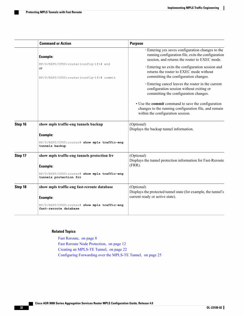
(Optional)Displays the backup tunnel information.
show mpls traffic-eng tunnels backup
Example:
RP/0/RSP0/CPU0:router# show mpls traffic-eng
Step 16
tunnels backup
(Optional)Displays the tunnel protection information for Fast-Reroute(FRR).
show mpls traffic-eng tunnels protection frr
Example:
RP/0/RSP0/CPU0:router# show mpls traffic-eng
Step 17
tunnels protection frr
(Optional)Displays the protected tunnel state (for example, the tunnel’scurrent ready or active state).
show mpls traffic-eng fast-reroute database
Example:
RP/0/RSP0/CPU0:router# show mpls traffic-eng
Step 18
fast-reroute database
Related Topics
Fast Reroute, on page 8Fast Reroute Node Protection, on page 12Creating an MPLS-TE Tunnel, on page 22Configuring Forwarding over the MPLS-TE Tunnel, on page 25
Cisco ASR 9000 Series Aggregation Services Router MPLS Configuration Guide, Release 4.032 OL-23109-02
Implementing MPLS Traffic EngineeringProtecting MPLS Tunnels with Fast Reroute
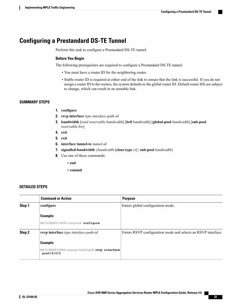
Configuring a Prestandard DS-TE TunnelPerform this task to configure a Prestandard DS-TE tunnel.
Before You Begin
The following prerequisites are required to configure a Prestandard DS-TE tunnel:
• You must have a router ID for the neighboring router.
• Stable router ID is required at either end of the link to ensure that the link is successful. If you do notassign a router ID to the routers, the system defaults to the global router ID. Default router IDs are subjectto change, which can result in an unstable link.
SUMMARY STEPS
1. configure2. rsvp interface type interface-path-id3. bandwidth [total reservable bandwidth] [bc0 bandwidth] [global-pool bandwidth] [sub-pool
reservable-bw]4. exit5. exit6. interface tunnel-te tunnel-id7. signalled-bandwidth {bandwidth [class-type ct] | sub-pool bandwidth}8. Use one of these commands:
• end
• commit
DETAILED STEPS
PurposeCommand or Action
Enters global configuration mode.configure
Example:
RP/0/RSP0/CPU0:router# configure
Step 1
Enters RSVP configuration mode and selects an RSVP interface.rsvp interface type interface-path-id
Example:
RP/0/RSP0/CPU0:router(config)# rsvp interface
Step 2
pos0/6/0/0
Cisco ASR 9000 Series Aggregation Services Router MPLS Configuration Guide, Release 4.0 OL-23109-02 33
Implementing MPLS Traffic EngineeringConfiguring a Prestandard DS-TE Tunnel
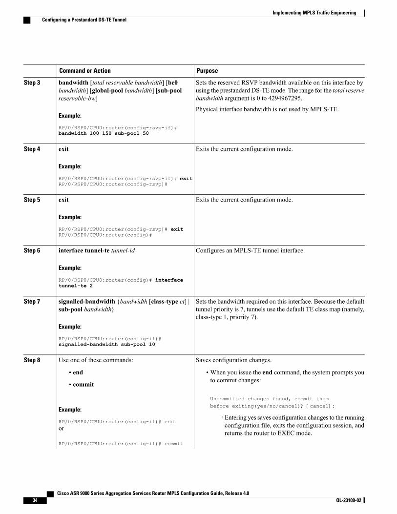
PurposeCommand or Action
Sets the reserved RSVP bandwidth available on this interface byusing the prestandard DS-TEmode. The range for the total reservebandwidth argument is 0 to 4294967295.
bandwidth [total reservable bandwidth] [bc0bandwidth] [global-pool bandwidth] [sub-poolreservable-bw]
Step 3
Example:
RP/0/RSP0/CPU0:router(config-rsvp-if)#
Physical interface bandwidth is not used by MPLS-TE.
bandwidth 100 150 sub-pool 50
Exits the current configuration mode.exit
Example:
RP/0/RSP0/CPU0:router(config-rsvp-if)# exit
Step 4
RP/0/RSP0/CPU0:router(config-rsvp)#
Exits the current configuration mode.exit
Example:
RP/0/RSP0/CPU0:router(config-rsvp)# exit
Step 5
RP/0/RSP0/CPU0:router(config)#
Configures an MPLS-TE tunnel interface.interface tunnel-te tunnel-id
Example:
RP/0/RSP0/CPU0:router(config)# interface
Step 6
tunnel-te 2
Sets the bandwidth required on this interface. Because the defaulttunnel priority is 7, tunnels use the default TE class map (namely,class-type 1, priority 7).
signalled-bandwidth {bandwidth [class-type ct] |sub-pool bandwidth}
Example:
RP/0/RSP0/CPU0:router(config-if)#
Step 7
signalled-bandwidth sub-pool 10
Saves configuration changes.Use one of these commands:Step 8
• end •When you issue the end command, the system prompts youto commit changes:
Uncommitted changes found, commit thembefore exiting(yes/no/cancel)? [cancel]:
• commit
Example:
RP/0/RSP0/CPU0:router(config-if)# end◦Entering yes saves configuration changes to the runningconfiguration file, exits the configuration session, andreturns the router to EXEC mode.
or
RP/0/RSP0/CPU0:router(config-if)# commit
Cisco ASR 9000 Series Aggregation Services Router MPLS Configuration Guide, Release 4.034 OL-23109-02
Implementing MPLS Traffic EngineeringConfiguring a Prestandard DS-TE Tunnel
PurposeCommand or Action
◦Entering no exits the configuration session and returnsthe router to EXEC mode without committing theconfiguration changes.
◦Entering cancel leaves the router in the currentconfiguration session without exiting or committingthe configuration changes.
• Use the commit command to save the configuration changesto the running configuration file, and remain within theconfiguration session.
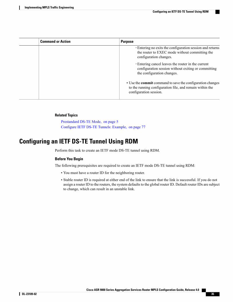
Related Topics
Prestandard DS-TE Mode, on page 5Configure IETF DS-TE Tunnels: Example, on page 77
Configuring an IETF DS-TE Tunnel Using RDMPerform this task to create an IETF mode DS-TE tunnel using RDM.
Before You Begin
The following prerequisites are required to create an IETF mode DS-TE tunnel using RDM:
• You must have a router ID for the neighboring router.
• Stable router ID is required at either end of the link to ensure that the link is successful. If you do notassign a router ID to the routers, the system defaults to the global router ID. Default router IDs are subjectto change, which can result in an unstable link.
Cisco ASR 9000 Series Aggregation Services Router MPLS Configuration Guide, Release 4.0 OL-23109-02 35
Implementing MPLS Traffic EngineeringConfiguring an IETF DS-TE Tunnel Using RDM
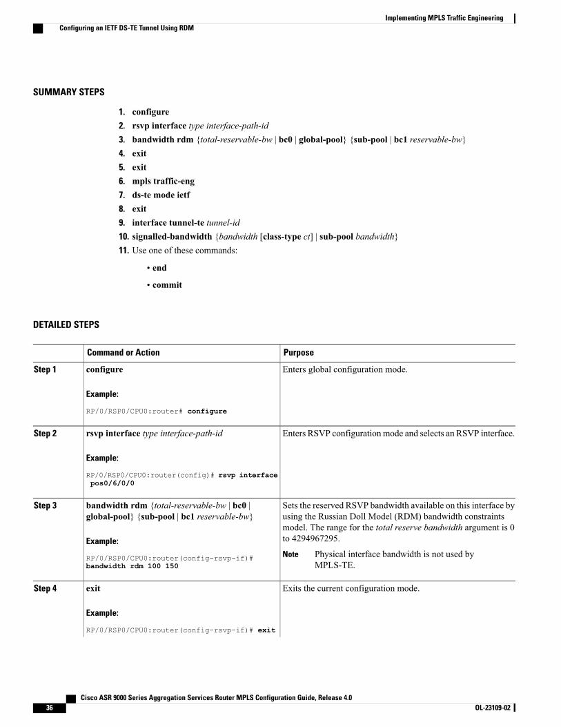
SUMMARY STEPS
1. configure2. rsvp interface type interface-path-id3. bandwidth rdm {total-reservable-bw | bc0 | global-pool} {sub-pool | bc1 reservable-bw}4. exit5. exit6. mpls traffic-eng7. ds-te mode ietf8. exit9. interface tunnel-te tunnel-id10. signalled-bandwidth {bandwidth [class-type ct] | sub-pool bandwidth}11. Use one of these commands:
• end
• commit
DETAILED STEPS
PurposeCommand or Action
Enters global configuration mode.configure
Example:
RP/0/RSP0/CPU0:router# configure
Step 1
Enters RSVP configuration mode and selects an RSVP interface.rsvp interface type interface-path-id
Example:
RP/0/RSP0/CPU0:router(config)# rsvp interface
Step 2
pos0/6/0/0
Sets the reserved RSVP bandwidth available on this interface byusing the Russian Doll Model (RDM) bandwidth constraints
bandwidth rdm {total-reservable-bw | bc0 |global-pool} {sub-pool | bc1 reservable-bw}
Step 3
model. The range for the total reserve bandwidth argument is 0to 4294967295.Example:
RP/0/RSP0/CPU0:router(config-rsvp-if)# Physical interface bandwidth is not used byMPLS-TE.
Notebandwidth rdm 100 150
Exits the current configuration mode.exit
Example:
RP/0/RSP0/CPU0:router(config-rsvp-if)# exit
Step 4
Cisco ASR 9000 Series Aggregation Services Router MPLS Configuration Guide, Release 4.036 OL-23109-02
Implementing MPLS Traffic EngineeringConfiguring an IETF DS-TE Tunnel Using RDM
PurposeCommand or Action
RP/0/RSP0/CPU0:router(config-rsvp)
Exits the current configuration mode.exit
Example:
RP/0/RSP0/CPU0:router(config-rsvp) exit
Step 5
RP/0/RSP0/CPU0:router(config)
Enters MPLS-TE configuration mode.mpls traffic-eng
Example:
RP/0/RSP0/CPU0:router(config)# mpls
Step 6
traffic-engRP/0/RSP0/CPU0:router(config-mpls-te)#
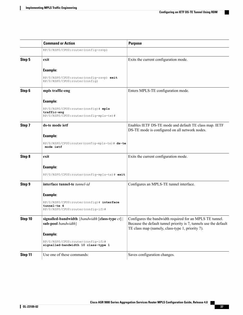
Enables IETF DS-TE mode and default TE class map. IETFDS-TE mode is configured on all network nodes.
ds-te mode ietf
Example:
RP/0/RSP0/CPU0:router(config-mpls-te)# ds-te
Step 7
mode ietf
Exits the current configuration mode.exit
Example:
RP/0/RSP0/CPU0:router(config-mpls-te)# exit
Step 8
Configures an MPLS-TE tunnel interface.interface tunnel-te tunnel-id
Example:
RP/0/RSP0/CPU0:router(config)# interface
Step 9
tunnel-te 4RP/0/RSP0/CPU0:router(config-if)#
Configures the bandwidth required for an MPLS TE tunnel.Because the default tunnel priority is 7, tunnels use the defaultTE class map (namely, class-type 1, priority 7).
signalled-bandwidth {bandwidth [class-type ct] |sub-pool bandwidth}
Example:
RP/0/RSP0/CPU0:router(config-if)#
Step 10
signalled-bandwidth 10 class-type 1
Saves configuration changes.Use one of these commands:Step 11
Cisco ASR 9000 Series Aggregation Services Router MPLS Configuration Guide, Release 4.0 OL-23109-02 37
Implementing MPLS Traffic EngineeringConfiguring an IETF DS-TE Tunnel Using RDM
PurposeCommand or Action
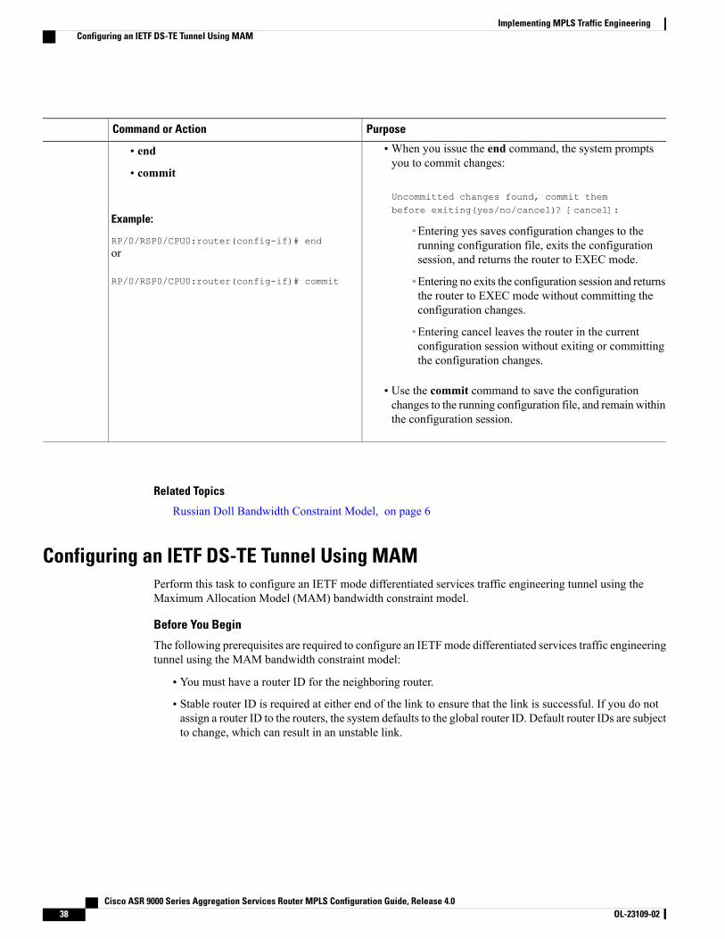
•When you issue the end command, the system promptsyou to commit changes:
Uncommitted changes found, commit thembefore exiting(yes/no/cancel)? [cancel]:
• end
• commit
Example:
RP/0/RSP0/CPU0:router(config-if)# end◦Entering yes saves configuration changes to therunning configuration file, exits the configurationsession, and returns the router to EXEC mode.or
RP/0/RSP0/CPU0:router(config-if)# commit ◦Entering no exits the configuration session and returnsthe router to EXEC mode without committing theconfiguration changes.
◦Entering cancel leaves the router in the currentconfiguration session without exiting or committingthe configuration changes.
• Use the commit command to save the configurationchanges to the running configuration file, and remain withinthe configuration session.
Related Topics
Russian Doll Bandwidth Constraint Model, on page 6
Configuring an IETF DS-TE Tunnel Using MAMPerform this task to configure an IETF mode differentiated services traffic engineering tunnel using theMaximum Allocation Model (MAM) bandwidth constraint model.
Before You Begin
The following prerequisites are required to configure an IETFmode differentiated services traffic engineeringtunnel using the MAM bandwidth constraint model:
• You must have a router ID for the neighboring router.
• Stable router ID is required at either end of the link to ensure that the link is successful. If you do notassign a router ID to the routers, the system defaults to the global router ID. Default router IDs are subjectto change, which can result in an unstable link.
Cisco ASR 9000 Series Aggregation Services Router MPLS Configuration Guide, Release 4.038 OL-23109-02
Implementing MPLS Traffic EngineeringConfiguring an IETF DS-TE Tunnel Using MAM
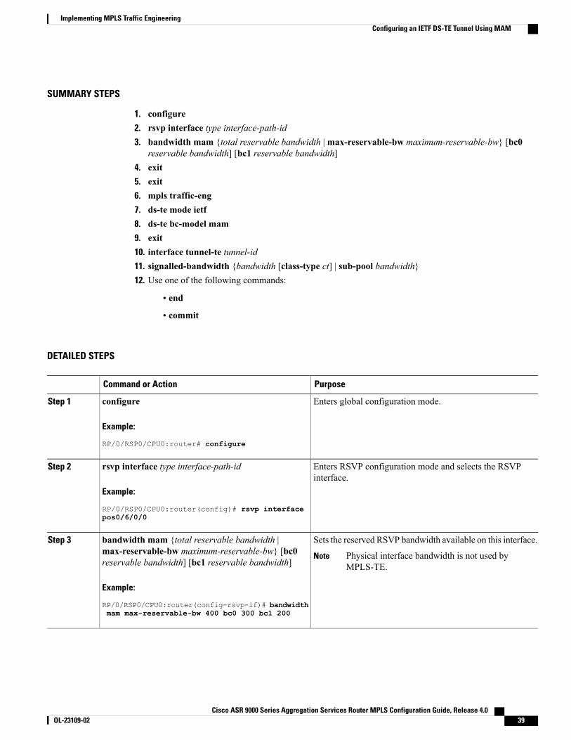
SUMMARY STEPS
1. configure2. rsvp interface type interface-path-id3. bandwidth mam {total reservable bandwidth |max-reservable-bw maximum-reservable-bw} [bc0
reservable bandwidth] [bc1 reservable bandwidth]4. exit5. exit6. mpls traffic-eng7. ds-te mode ietf8. ds-te bc-model mam9. exit10. interface tunnel-te tunnel-id11. signalled-bandwidth {bandwidth [class-type ct] | sub-pool bandwidth}12. Use one of the following commands:
• end
• commit
DETAILED STEPS
PurposeCommand or Action
Enters global configuration mode.configure
Example:
RP/0/RSP0/CPU0:router# configure
Step 1
Enters RSVP configuration mode and selects the RSVPinterface.
rsvp interface type interface-path-id
Example:
RP/0/RSP0/CPU0:router(config)# rsvp interface
Step 2
pos0/6/0/0
Sets the reserved RSVP bandwidth available on this interface.bandwidth mam {total reservable bandwidth |max-reservable-bw maximum-reservable-bw} [bc0reservable bandwidth] [bc1 reservable bandwidth]
Step 3
Physical interface bandwidth is not used byMPLS-TE.
Note
Example:
RP/0/RSP0/CPU0:router(config-rsvp-if)# bandwidthmam max-reservable-bw 400 bc0 300 bc1 200
Cisco ASR 9000 Series Aggregation Services Router MPLS Configuration Guide, Release 4.0 OL-23109-02 39
Implementing MPLS Traffic EngineeringConfiguring an IETF DS-TE Tunnel Using MAM
PurposeCommand or Action
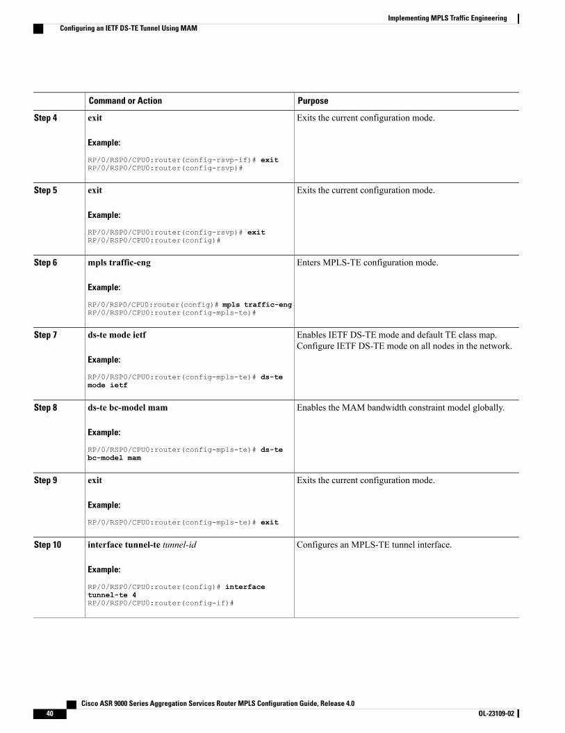
Exits the current configuration mode.exit
Example:
RP/0/RSP0/CPU0:router(config-rsvp-if)# exit
Step 4
RP/0/RSP0/CPU0:router(config-rsvp)#
Exits the current configuration mode.exit
Example:
RP/0/RSP0/CPU0:router(config-rsvp)# exit
Step 5
RP/0/RSP0/CPU0:router(config)#
Enters MPLS-TE configuration mode.mpls traffic-eng
Example:
RP/0/RSP0/CPU0:router(config)# mpls traffic-eng
Step 6
RP/0/RSP0/CPU0:router(config-mpls-te)#
Enables IETF DS-TE mode and default TE class map.Configure IETF DS-TE mode on all nodes in the network.
ds-te mode ietf
Example:
RP/0/RSP0/CPU0:router(config-mpls-te)# ds-te
Step 7
mode ietf
Enables the MAM bandwidth constraint model globally.ds-te bc-model mam
Example:
RP/0/RSP0/CPU0:router(config-mpls-te)# ds-te
Step 8
bc-model mam
Exits the current configuration mode.exit
Example:
RP/0/RSP0/CPU0:router(config-mpls-te)# exit
Step 9
Configures an MPLS-TE tunnel interface.interface tunnel-te tunnel-id
Example:
RP/0/RSP0/CPU0:router(config)# interface
Step 10
tunnel-te 4RP/0/RSP0/CPU0:router(config-if)#
Cisco ASR 9000 Series Aggregation Services Router MPLS Configuration Guide, Release 4.040 OL-23109-02
Implementing MPLS Traffic EngineeringConfiguring an IETF DS-TE Tunnel Using MAM
PurposeCommand or Action
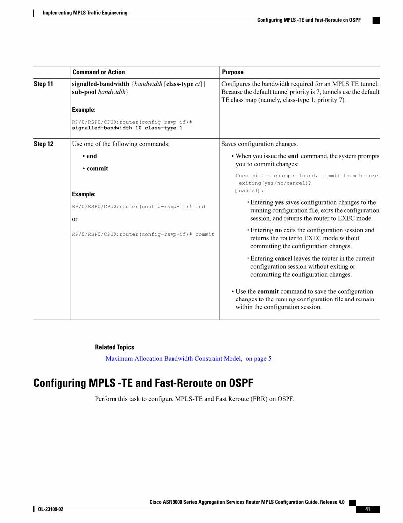
Configures the bandwidth required for an MPLS TE tunnel.Because the default tunnel priority is 7, tunnels use the defaultTE class map (namely, class-type 1, priority 7).
signalled-bandwidth {bandwidth [class-type ct] |sub-pool bandwidth}
Example:
RP/0/RSP0/CPU0:router(config-rsvp-if)#
Step 11
signalled-bandwidth 10 class-type 1
Saves configuration changes.Use one of the following commands:Step 12
• end •When you issue the end command, the system promptsyou to commit changes:
Uncommitted changes found, commit them beforeexiting(yes/no/cancel)?[cancel]:
• commit
Example:
RP/0/RSP0/CPU0:router(config-rsvp-if)# end◦Entering yes saves configuration changes to therunning configuration file, exits the configurationsession, and returns the router to EXEC mode.or
RP/0/RSP0/CPU0:router(config-rsvp-if)# commit◦Entering no exits the configuration session andreturns the router to EXEC mode withoutcommitting the configuration changes.
◦Entering cancel leaves the router in the currentconfiguration session without exiting orcommitting the configuration changes.
• Use the commit command to save the configurationchanges to the running configuration file and remainwithin the configuration session.
Related Topics
Maximum Allocation Bandwidth Constraint Model, on page 5
Configuring MPLS -TE and Fast-Reroute on OSPFPerform this task to configure MPLS-TE and Fast Reroute (FRR) on OSPF.
Cisco ASR 9000 Series Aggregation Services Router MPLS Configuration Guide, Release 4.0 OL-23109-02 41
Implementing MPLS Traffic EngineeringConfiguring MPLS -TE and Fast-Reroute on OSPF
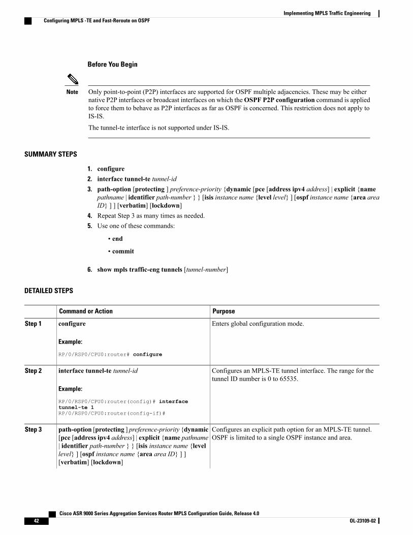
Before You Begin
Only point-to-point (P2P) interfaces are supported for OSPF multiple adjacencies. These may be eithernative P2P interfaces or broadcast interfaces on which theOSPF P2P configuration command is appliedto force them to behave as P2P interfaces as far as OSPF is concerned. This restriction does not apply toIS-IS.
The tunnel-te interface is not supported under IS-IS.
Note
SUMMARY STEPS
1. configure2. interface tunnel-te tunnel-id3. path-option [protecting ] preference-priority {dynamic [pce [address ipv4 address] | explicit {name
pathname | identifier path-number } } [isis instance name {level level} ] [ospf instance name {area areaID} ] ] [verbatim] [lockdown]
4. Repeat Step 3 as many times as needed.5. Use one of these commands:
• end
• commit
6. show mpls traffic-eng tunnels [tunnel-number]
DETAILED STEPS
PurposeCommand or Action
Enters global configuration mode.configure
Example:
RP/0/RSP0/CPU0:router# configure
Step 1
Configures an MPLS-TE tunnel interface. The range for thetunnel ID number is 0 to 65535.
interface tunnel-te tunnel-id
Example:
RP/0/RSP0/CPU0:router(config)# interface
Step 2
tunnel-te 1RP/0/RSP0/CPU0:router(config-if)#
Configures an explicit path option for an MPLS-TE tunnel.OSPF is limited to a single OSPF instance and area.
path-option [protecting ] preference-priority {dynamic[pce [address ipv4 address] | explicit {name pathname| identifier path-number } } [isis instance name {level
Step 3
level} ] [ospf instance name {area area ID} ] ][verbatim] [lockdown]
Cisco ASR 9000 Series Aggregation Services Router MPLS Configuration Guide, Release 4.042 OL-23109-02
Implementing MPLS Traffic EngineeringConfiguring MPLS -TE and Fast-Reroute on OSPF
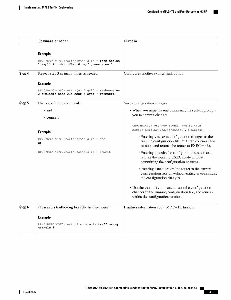
PurposeCommand or Action
Example:
RP/0/RSP0/CPU0:router(config-if)# path-option1 explicit identifier 6 ospf green area 0
Configures another explicit path option.Repeat Step 3 as many times as needed.
Example:
RP/0/RSP0/CPU0:router(config-if)# path-option
Step 4
2 explicit name 234 ospf 3 area 7 verbatim
Saves configuration changes.Use one of these commands:Step 5
• end •When you issue the end command, the system promptsyou to commit changes:
Uncommitted changes found, commit thembefore exiting(yes/no/cancel)? [cancel]:
• commit
Example:
RP/0/RSP0/CPU0:router(config-if)# end◦Entering yes saves configuration changes to therunning configuration file, exits the configurationsession, and returns the router to EXEC mode.
or
RP/0/RSP0/CPU0:router(config-if)# commit ◦Entering no exits the configuration session andreturns the router to EXEC mode withoutcommitting the configuration changes.
◦Entering cancel leaves the router in the currentconfiguration session without exiting or committingthe configuration changes.
• Use the commit command to save the configurationchanges to the running configuration file, and remainwithin the configuration session.
Displays information about MPLS-TE tunnels.show mpls traffic-eng tunnels [tunnel-number]
Example:
RP/0/RSP0/CPU0:router# show mpls traffic-eng
Step 6
tunnels 1
Cisco ASR 9000 Series Aggregation Services Router MPLS Configuration Guide, Release 4.0 OL-23109-02 43
Implementing MPLS Traffic EngineeringConfiguring MPLS -TE and Fast-Reroute on OSPF

Configuring the Ignore Integrated IS-IS Overload Bit Setting in MPLS-TEPerform this task to configure an overload node avoidance in MPLS-TE. When the overload bit is enabled,tunnels are brought down when the overload node is found in the tunnel path.
SUMMARY STEPS
1. configure2. mpls traffic-eng3. path-selection ignore overload4. Use one of these commands:
• end
• commit
DETAILED STEPS
PurposeCommand or Action
Enters global configuration mode.configure
Example:
RP/0/RSP0/CPU0:router# configure
Step 1
Enters MPLS-TE configuration mode.mpls traffic-eng
Example:
RP/0/RSP0/CPU0:router(config)# mpls
Step 2
traffic-engRP/0/RSP0/CPU0:router(config-mpls-te)#
Ignores the Intermediate System-to-Intermediate System (IS-IS) overloadbit setting for MPLS-TE.
path-selection ignore overload
Example:
RP/0/RSP0/CPU0:router(config-mpls-te)#
Step 3
path-selection ignore overload
Saves configuration changes.Use one of these commands:Step 4
• end •When you issue the end command, the system prompts you tocommit changes:
Uncommitted changes found, commit them beforeexiting(yes/no/cancel)?[cancel]:
• commit
Example:
RP/0/RSP0/CPU0:router(config-mpls-te)#
Cisco ASR 9000 Series Aggregation Services Router MPLS Configuration Guide, Release 4.044 OL-23109-02
Implementing MPLS Traffic EngineeringConfiguring the Ignore Integrated IS-IS Overload Bit Setting in MPLS-TE
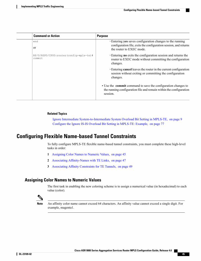
PurposeCommand or Action
◦Entering yes saves configuration changes to the runningconfiguration file, exits the configuration session, and returnsthe router to EXEC mode.
end
or
RP/0/RSP0/CPU0:router(config-mpls-te)# ◦Entering no exits the configuration session and returns therouter to EXECmode without committing the configurationchanges.
commit
◦Entering cancel leaves the router in the current configurationsession without exiting or committing the configurationchanges.
• Use the commit command to save the configuration changes tothe running configuration file and remain within the configurationsession.
Related Topics
Ignore Intermediate System-to-Intermediate System Overload Bit Setting in MPLS-TE, on page 9Configure the Ignore IS-IS Overload Bit Setting in MPLS-TE: Example, on page 77
Configuring Flexible Name-based Tunnel ConstraintsTo fully configure MPLS-TE flexible name-based tunnel constraints, you must complete these high-leveltasks in order:
1 Assigning Color Names to Numeric Values, on page 45
2 Associating Affinity-Names with TE Links, on page 47
3 Associating Affinity Constraints for TE Tunnels, on page 49
Assigning Color Names to Numeric ValuesThe first task in enabling the new coloring scheme is to assign a numerical value (in hexadecimal) to eachvalue (color).
An affinity color name cannot exceed 64 characters. An affinity value cannot exceed a single digit. Forexample, magenta1.
Note
Cisco ASR 9000 Series Aggregation Services Router MPLS Configuration Guide, Release 4.0 OL-23109-02 45
Implementing MPLS Traffic EngineeringConfiguring Flexible Name-based Tunnel Constraints
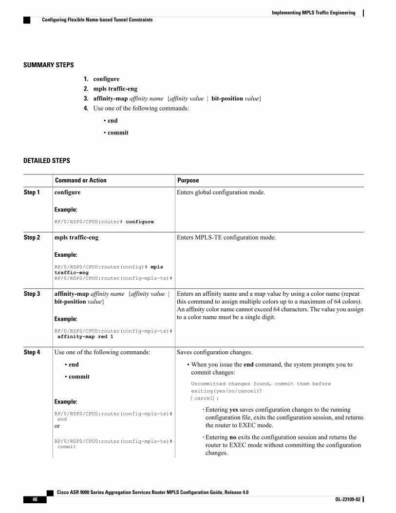
SUMMARY STEPS
1. configure2. mpls traffic-eng3. affinity-map affinity name {affinity value | bit-position value}4. Use one of the following commands:
• end
• commit
DETAILED STEPS
PurposeCommand or Action
Enters global configuration mode.configure
Example:
RP/0/RSP0/CPU0:router# configure
Step 1
Enters MPLS-TE configuration mode.mpls traffic-eng
Example:
RP/0/RSP0/CPU0:router(config)# mpls
Step 2
traffic-engRP/0/RSP0/CPU0:router(config-mpls-te)#
Enters an affinity name and a map value by using a color name (repeatthis command to assign multiple colors up to a maximum of 64 colors).
affinity-map affinity name {affinity value |bit-position value}
Step 3
An affinity color name cannot exceed 64 characters. The value you assignto a color name must be a single digit.Example:
RP/0/RSP0/CPU0:router(config-mpls-te)#affinity-map red 1
Saves configuration changes.Use one of the following commands:Step 4
• end •When you issue the end command, the system prompts you tocommit changes:
Uncommitted changes found, commit them beforeexiting(yes/no/cancel)?[cancel]:
• commit
Example:
RP/0/RSP0/CPU0:router(config-mpls-te)#end
◦Entering yes saves configuration changes to the runningconfiguration file, exits the configuration session, and returnsthe router to EXEC mode.or
RP/0/RSP0/CPU0:router(config-mpls-te)#commit
◦Entering no exits the configuration session and returns therouter to EXEC mode without committing the configurationchanges.
Cisco ASR 9000 Series Aggregation Services Router MPLS Configuration Guide, Release 4.046 OL-23109-02
Implementing MPLS Traffic EngineeringConfiguring Flexible Name-based Tunnel Constraints
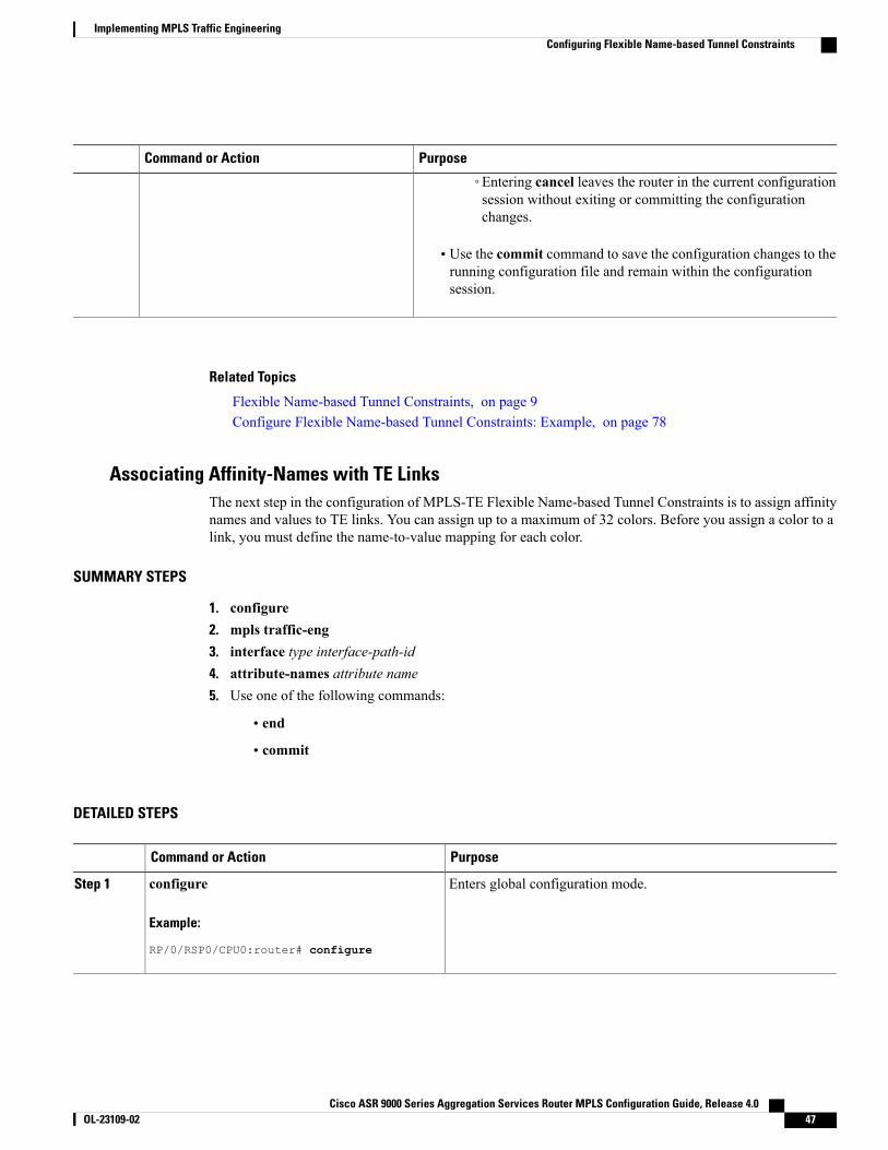
PurposeCommand or Action
◦Entering cancel leaves the router in the current configurationsession without exiting or committing the configurationchanges.
• Use the commit command to save the configuration changes to therunning configuration file and remain within the configurationsession.
Related Topics
Flexible Name-based Tunnel Constraints, on page 9Configure Flexible Name-based Tunnel Constraints: Example, on page 78
Associating Affinity-Names with TE LinksThe next step in the configuration of MPLS-TE Flexible Name-based Tunnel Constraints is to assign affinitynames and values to TE links. You can assign up to a maximum of 32 colors. Before you assign a color to alink, you must define the name-to-value mapping for each color.
SUMMARY STEPS
1. configure2. mpls traffic-eng3. interface type interface-path-id4. attribute-names attribute name5. Use one of the following commands:
• end
• commit
DETAILED STEPS
PurposeCommand or Action
Enters global configuration mode.configure
Example:
RP/0/RSP0/CPU0:router# configure
Step 1
Cisco ASR 9000 Series Aggregation Services Router MPLS Configuration Guide, Release 4.0 OL-23109-02 47
Implementing MPLS Traffic EngineeringConfiguring Flexible Name-based Tunnel Constraints
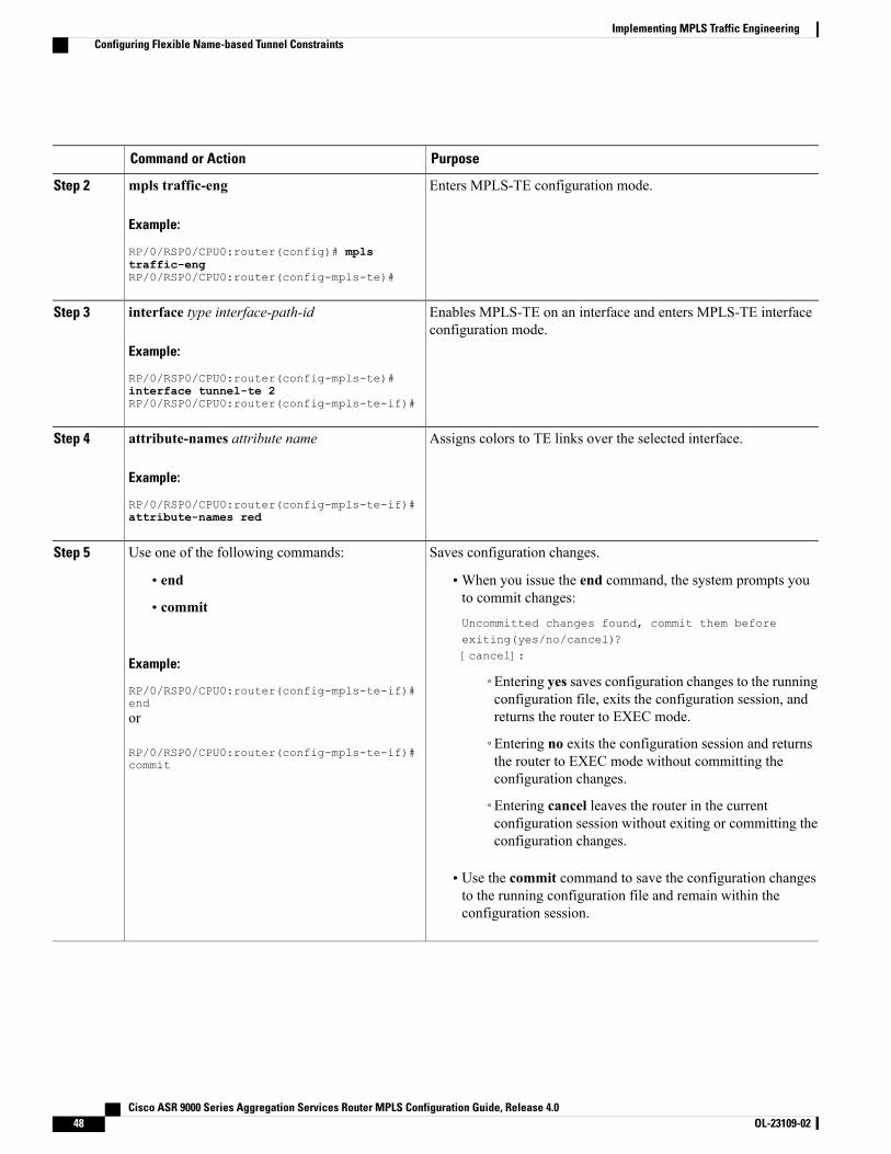
PurposeCommand or Action
Enters MPLS-TE configuration mode.mpls traffic-eng
Example:
RP/0/RSP0/CPU0:router(config)# mpls
Step 2
traffic-engRP/0/RSP0/CPU0:router(config-mpls-te)#
Enables MPLS-TE on an interface and enters MPLS-TE interfaceconfiguration mode.
interface type interface-path-id
Example:
RP/0/RSP0/CPU0:router(config-mpls-te)#
Step 3
interface tunnel-te 2RP/0/RSP0/CPU0:router(config-mpls-te-if)#
Assigns colors to TE links over the selected interface.attribute-names attribute name
Example:
RP/0/RSP0/CPU0:router(config-mpls-te-if)#
Step 4
attribute-names red
Saves configuration changes.Use one of the following commands:Step 5
• end •When you issue the end command, the system prompts youto commit changes:
Uncommitted changes found, commit them beforeexiting(yes/no/cancel)?[cancel]:
• commit
Example:
RP/0/RSP0/CPU0:router(config-mpls-te-if)#end
◦Entering yes saves configuration changes to the runningconfiguration file, exits the configuration session, andreturns the router to EXEC mode.or
RP/0/RSP0/CPU0:router(config-mpls-te-if)#commit
◦Entering no exits the configuration session and returnsthe router to EXEC mode without committing theconfiguration changes.
◦Entering cancel leaves the router in the currentconfiguration session without exiting or committing theconfiguration changes.
• Use the commit command to save the configuration changesto the running configuration file and remain within theconfiguration session.
Cisco ASR 9000 Series Aggregation Services Router MPLS Configuration Guide, Release 4.048 OL-23109-02
Implementing MPLS Traffic EngineeringConfiguring Flexible Name-based Tunnel Constraints
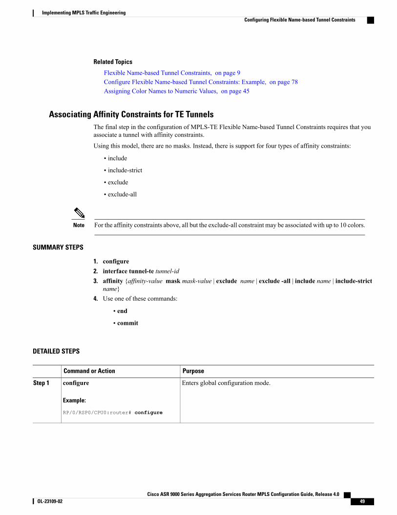
Related Topics
Flexible Name-based Tunnel Constraints, on page 9Configure Flexible Name-based Tunnel Constraints: Example, on page 78Assigning Color Names to Numeric Values, on page 45
Associating Affinity Constraints for TE TunnelsThe final step in the configuration of MPLS-TE Flexible Name-based Tunnel Constraints requires that youassociate a tunnel with affinity constraints.
Using this model, there are no masks. Instead, there is support for four types of affinity constraints:
• include
• include-strict
• exclude
• exclude-all
For the affinity constraints above, all but the exclude-all constraint may be associated with up to 10 colors.Note
SUMMARY STEPS
1. configure2. interface tunnel-te tunnel-id3. affinity {affinity-value mask mask-value | exclude name | exclude -all | include name | include-strict
name}4. Use one of these commands:
• end
• commit
DETAILED STEPS
PurposeCommand or Action
Enters global configuration mode.configure
Example:
RP/0/RSP0/CPU0:router# configure
Step 1
Cisco ASR 9000 Series Aggregation Services Router MPLS Configuration Guide, Release 4.0 OL-23109-02 49
Implementing MPLS Traffic EngineeringConfiguring Flexible Name-based Tunnel Constraints
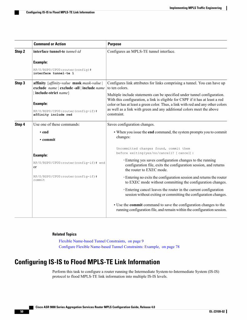
PurposeCommand or Action
Configures an MPLS-TE tunnel interface.interface tunnel-te tunnel-id
Example:
RP/0/RSP0/CPU0:router(config)#
Step 2
interface tunnel-te 1
Configures link attributes for links comprising a tunnel. You can have upto ten colors.
affinity {affinity-value mask mask-value |exclude name | exclude -all | include name| include-strict name}
Step 3
Multiple include statements can be specified under tunnel configuration.With this configuration, a link is eligible for CSPF if it has at least a red
Example:
RP/0/RSP0/CPU0:router(config-if)#
color or has at least a green color. Thus, a link with red and any other colorsas well as a link with green and any additional colors meet the aboveconstraint.affinity include red
Saves configuration changes.Use one of these commands:Step 4
• end •When you issue the end command, the system prompts you to commitchanges:
Uncommitted changes found, commit thembefore exiting(yes/no/cancel)? [cancel]:
• commit
Example:
RP/0/RSP0/CPU0:router(config-if)# end◦Entering yes saves configuration changes to the runningconfiguration file, exits the configuration session, and returnsthe router to EXEC mode.
or
RP/0/RSP0/CPU0:router(config-if)#commit
◦Entering no exits the configuration session and returns the routerto EXEC mode without committing the configuration changes.
◦Entering cancel leaves the router in the current configurationsession without exiting or committing the configuration changes.
• Use the commit command to save the configuration changes to therunning configuration file, and remainwithin the configuration session.
Related Topics
Flexible Name-based Tunnel Constraints, on page 9Configure Flexible Name-based Tunnel Constraints: Example, on page 78
Configuring IS-IS to Flood MPLS-TE Link InformationPerform this task to configure a router running the Intermediate System-to-Intermediate System (IS-IS)protocol to flood MPLS-TE link information into multiple IS-IS levels.
Cisco ASR 9000 Series Aggregation Services Router MPLS Configuration Guide, Release 4.050 OL-23109-02
Implementing MPLS Traffic EngineeringConfiguring IS-IS to Flood MPLS-TE Link Information
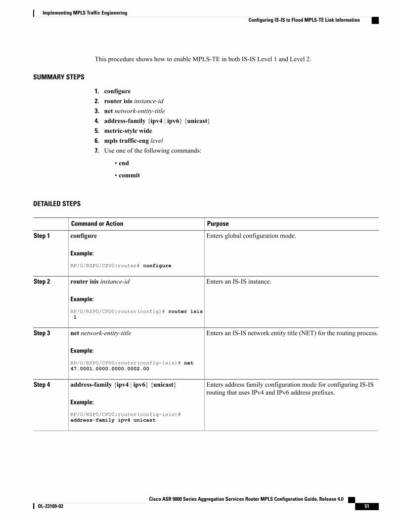
This procedure shows how to enable MPLS-TE in both IS-IS Level 1 and Level 2.
SUMMARY STEPS
1. configure2. router isis instance-id3. net network-entity-title4. address-family {ipv4 | ipv6} {unicast}5. metric-style wide6. mpls traffic-eng level7. Use one of the following commands:
• end
• commit
DETAILED STEPS
PurposeCommand or Action
Enters global configuration mode.configure
Example:
RP/0/RSP0/CPU0:router# configure
Step 1
Enters an IS-IS instance.router isis instance-id
Example:
RP/0/RSP0/CPU0:router(config)# router isis
Step 2
1
Enters an IS-IS network entity title (NET) for the routing process.net network-entity-title
Example:
RP/0/RSP0/CPU0:router(config-isis)# net
Step 3
47.0001.0000.0000.0002.00
Enters address family configuration mode for configuring IS-ISrouting that uses IPv4 and IPv6 address prefixes.
address-family {ipv4 | ipv6} {unicast}
Example:
RP/0/RSP0/CPU0:router(config-isis)#
Step 4
address-family ipv4 unicast
Cisco ASR 9000 Series Aggregation Services Router MPLS Configuration Guide, Release 4.0 OL-23109-02 51
Implementing MPLS Traffic EngineeringConfiguring IS-IS to Flood MPLS-TE Link Information
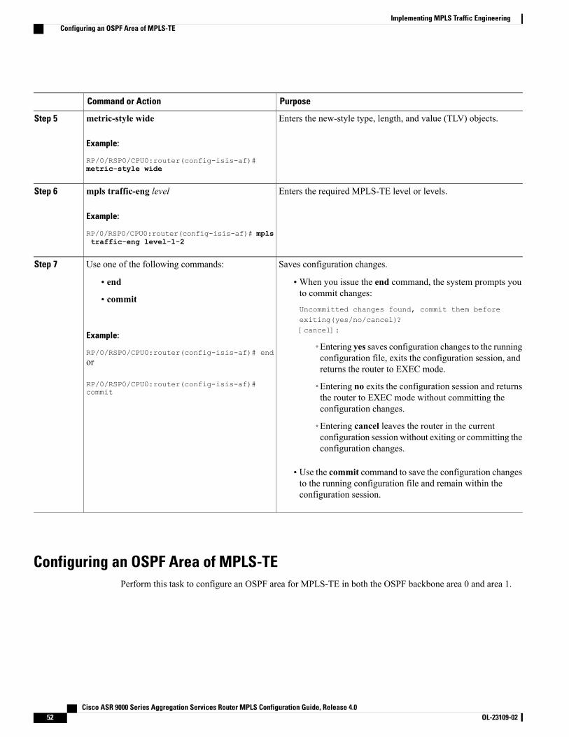
PurposeCommand or Action
Enters the new-style type, length, and value (TLV) objects.metric-style wide
Example:
RP/0/RSP0/CPU0:router(config-isis-af)#
Step 5
metric-style wide
Enters the required MPLS-TE level or levels.mpls traffic-eng level
Example:
RP/0/RSP0/CPU0:router(config-isis-af)# mpls
Step 6
traffic-eng level-1-2
Saves configuration changes.Use one of the following commands:Step 7
• end •When you issue the end command, the system prompts youto commit changes:
Uncommitted changes found, commit them beforeexiting(yes/no/cancel)?[cancel]:
• commit
Example:
RP/0/RSP0/CPU0:router(config-isis-af)# end◦Entering yes saves configuration changes to the runningconfiguration file, exits the configuration session, andreturns the router to EXEC mode.
or
RP/0/RSP0/CPU0:router(config-isis-af)#commit
◦Entering no exits the configuration session and returnsthe router to EXEC mode without committing theconfiguration changes.
◦Entering cancel leaves the router in the currentconfiguration session without exiting or committing theconfiguration changes.
• Use the commit command to save the configuration changesto the running configuration file and remain within theconfiguration session.
Configuring an OSPF Area of MPLS-TEPerform this task to configure an OSPF area for MPLS-TE in both the OSPF backbone area 0 and area 1.
Cisco ASR 9000 Series Aggregation Services Router MPLS Configuration Guide, Release 4.052 OL-23109-02
Implementing MPLS Traffic EngineeringConfiguring an OSPF Area of MPLS-TE
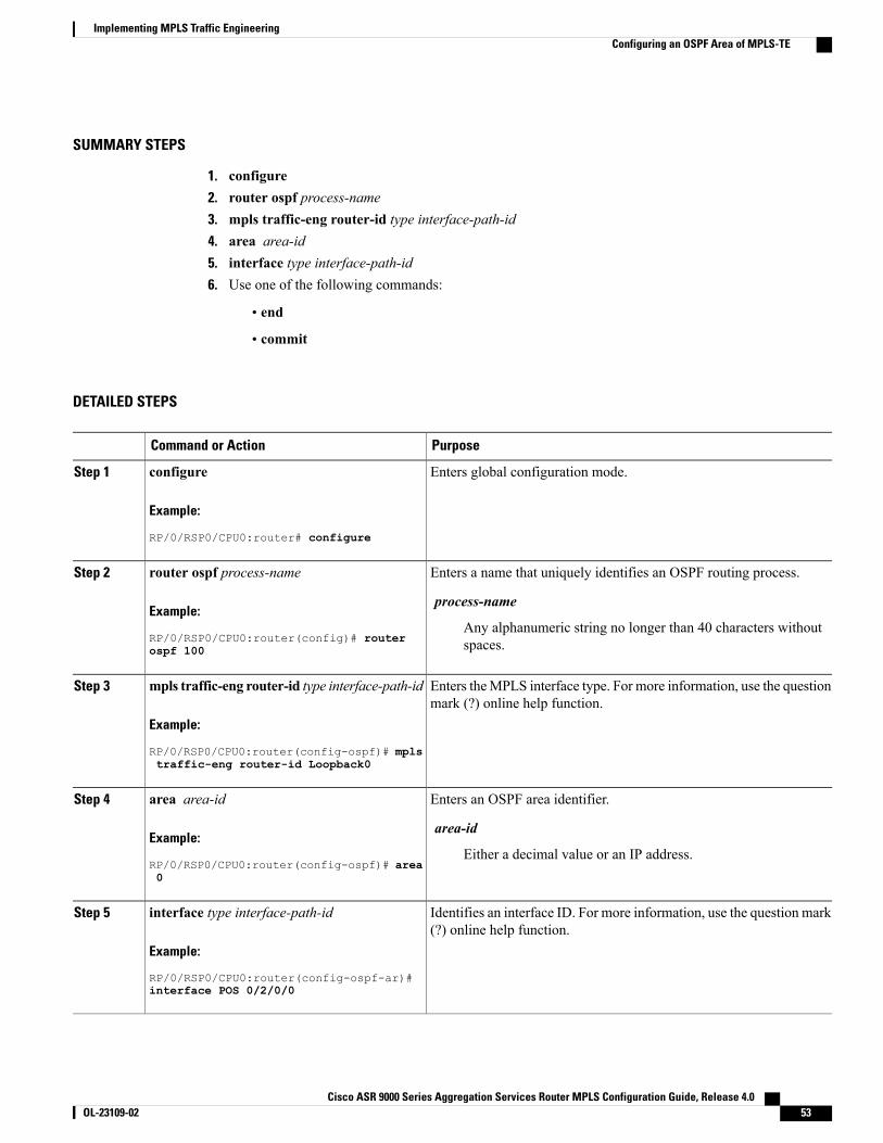
SUMMARY STEPS
1. configure2. router ospf process-name3. mpls traffic-eng router-id type interface-path-id4. area area-id5. interface type interface-path-id6. Use one of the following commands:
• end
• commit
DETAILED STEPS
PurposeCommand or Action
Enters global configuration mode.configure
Example:
RP/0/RSP0/CPU0:router# configure
Step 1
Enters a name that uniquely identifies an OSPF routing process.router ospf process-name
Example:
RP/0/RSP0/CPU0:router(config)# router
Step 2
process-name
Any alphanumeric string no longer than 40 characters withoutspaces.ospf 100
Enters theMPLS interface type. For more information, use the questionmark (?) online help function.
mpls traffic-eng router-id type interface-path-id
Example:
RP/0/RSP0/CPU0:router(config-ospf)# mpls
Step 3
traffic-eng router-id Loopback0
Enters an OSPF area identifier.area area-id
Example:
RP/0/RSP0/CPU0:router(config-ospf)# area
Step 4
area-id
Either a decimal value or an IP address.0
Identifies an interface ID. For more information, use the question mark(?) online help function.
interface type interface-path-id
Example:
RP/0/RSP0/CPU0:router(config-ospf-ar)#
Step 5
interface POS 0/2/0/0
Cisco ASR 9000 Series Aggregation Services Router MPLS Configuration Guide, Release 4.0 OL-23109-02 53
Implementing MPLS Traffic EngineeringConfiguring an OSPF Area of MPLS-TE
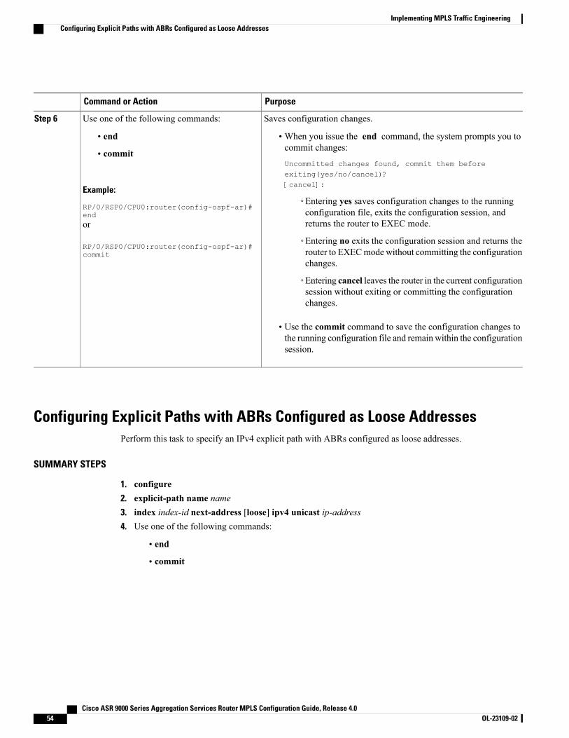
PurposeCommand or Action
Saves configuration changes.Use one of the following commands:Step 6
• end •When you issue the end command, the system prompts you tocommit changes:
Uncommitted changes found, commit them beforeexiting(yes/no/cancel)?[cancel]:
• commit
Example:
RP/0/RSP0/CPU0:router(config-ospf-ar)#end
◦Entering yes saves configuration changes to the runningconfiguration file, exits the configuration session, andreturns the router to EXEC mode.or
RP/0/RSP0/CPU0:router(config-ospf-ar)#commit
◦Entering no exits the configuration session and returns therouter to EXECmode without committing the configurationchanges.
◦Entering cancel leaves the router in the current configurationsession without exiting or committing the configurationchanges.
• Use the commit command to save the configuration changes tothe running configuration file and remain within the configurationsession.
Configuring Explicit Paths with ABRs Configured as Loose AddressesPerform this task to specify an IPv4 explicit path with ABRs configured as loose addresses.
SUMMARY STEPS
1. configure2. explicit-path name name3. index index-id next-address [loose] ipv4 unicast ip-address4. Use one of the following commands:
• end
• commit
Cisco ASR 9000 Series Aggregation Services Router MPLS Configuration Guide, Release 4.054 OL-23109-02
Implementing MPLS Traffic EngineeringConfiguring Explicit Paths with ABRs Configured as Loose Addresses
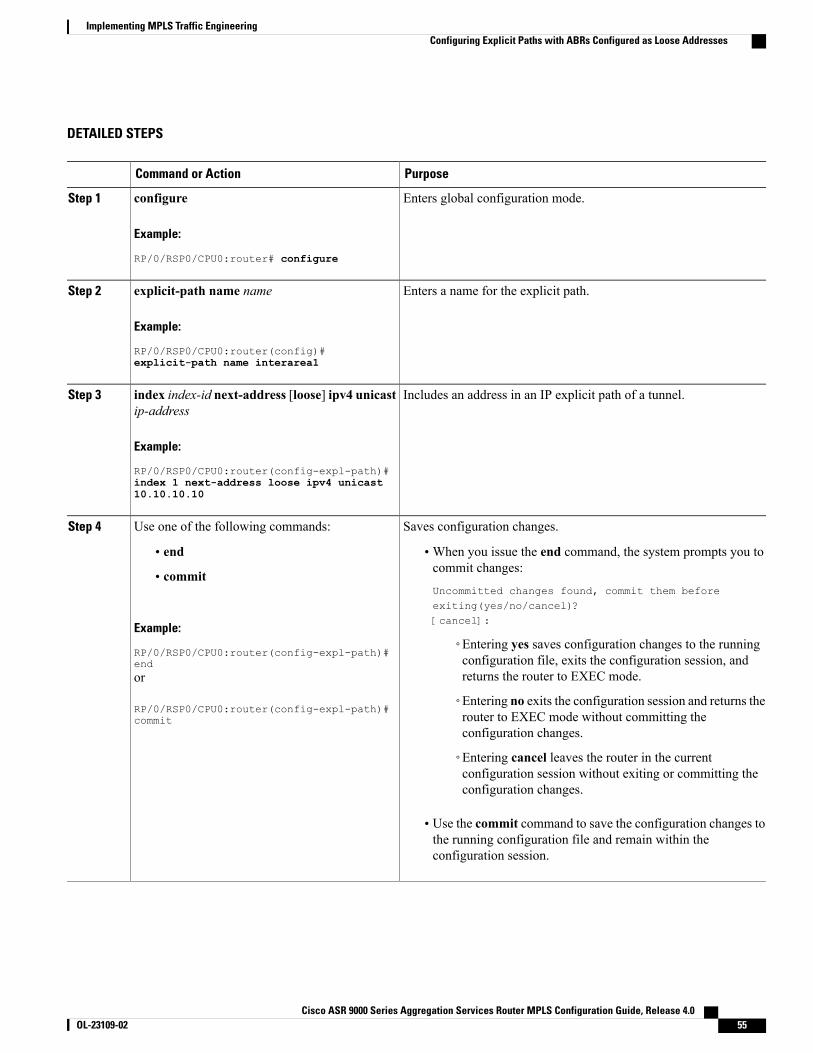
DETAILED STEPS
PurposeCommand or Action
Enters global configuration mode.configure
Example:
RP/0/RSP0/CPU0:router# configure
Step 1
Enters a name for the explicit path.explicit-path name name
Example:
RP/0/RSP0/CPU0:router(config)#
Step 2
explicit-path name interarea1
Includes an address in an IP explicit path of a tunnel.index index-id next-address [loose] ipv4 unicastip-address
Step 3
Example:
RP/0/RSP0/CPU0:router(config-expl-path)#index 1 next-address loose ipv4 unicast10.10.10.10
Saves configuration changes.Use one of the following commands:Step 4
• end •When you issue the end command, the system prompts you tocommit changes:
Uncommitted changes found, commit them beforeexiting(yes/no/cancel)?[cancel]:
• commit
Example:
RP/0/RSP0/CPU0:router(config-expl-path)#end
◦Entering yes saves configuration changes to the runningconfiguration file, exits the configuration session, andreturns the router to EXEC mode.or
RP/0/RSP0/CPU0:router(config-expl-path)#commit
◦Entering no exits the configuration session and returns therouter to EXEC mode without committing theconfiguration changes.
◦Entering cancel leaves the router in the currentconfiguration session without exiting or committing theconfiguration changes.
• Use the commit command to save the configuration changes tothe running configuration file and remain within theconfiguration session.
Cisco ASR 9000 Series Aggregation Services Router MPLS Configuration Guide, Release 4.0 OL-23109-02 55
Implementing MPLS Traffic EngineeringConfiguring Explicit Paths with ABRs Configured as Loose Addresses
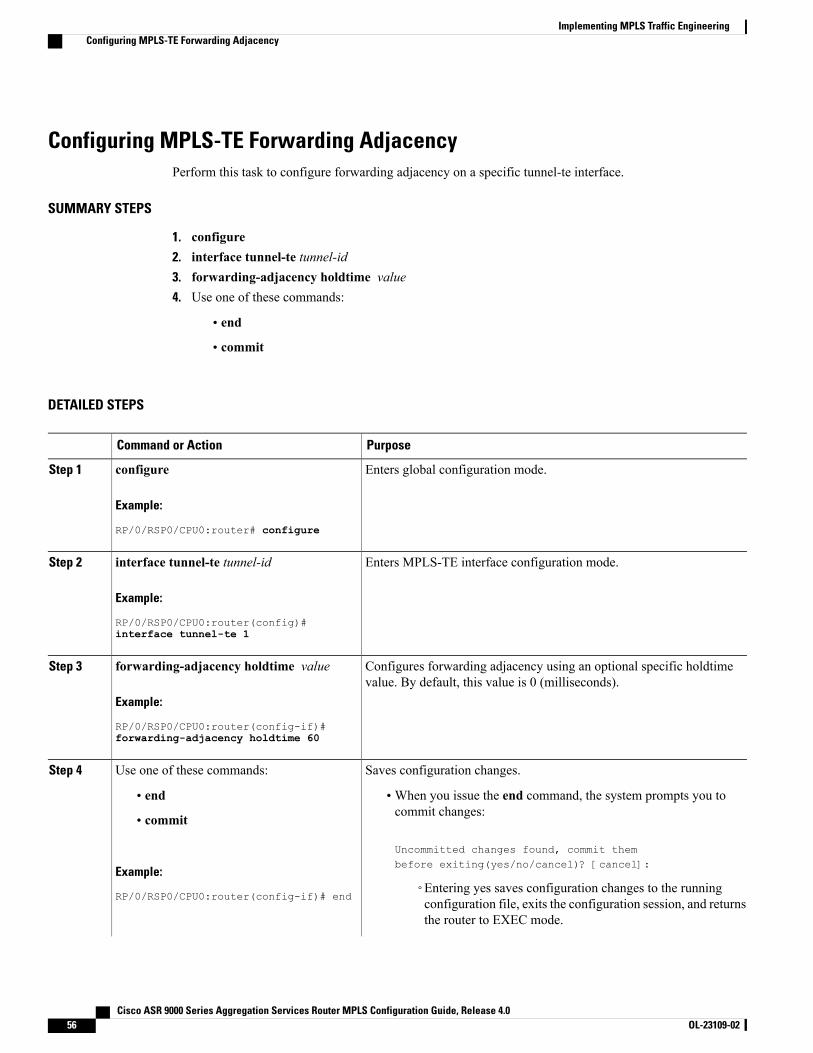
Configuring MPLS-TE Forwarding AdjacencyPerform this task to configure forwarding adjacency on a specific tunnel-te interface.
SUMMARY STEPS
1. configure2. interface tunnel-te tunnel-id3. forwarding-adjacency holdtime value4. Use one of these commands:
• end
• commit
DETAILED STEPS
PurposeCommand or Action
Enters global configuration mode.configure
Example:
RP/0/RSP0/CPU0:router# configure
Step 1
Enters MPLS-TE interface configuration mode.interface tunnel-te tunnel-id
Example:
RP/0/RSP0/CPU0:router(config)#
Step 2
interface tunnel-te 1
Configures forwarding adjacency using an optional specific holdtimevalue. By default, this value is 0 (milliseconds).
forwarding-adjacency holdtime value
Example:
RP/0/RSP0/CPU0:router(config-if)#
Step 3
forwarding-adjacency holdtime 60
Saves configuration changes.Use one of these commands:Step 4
• end •When you issue the end command, the system prompts you tocommit changes:
Uncommitted changes found, commit thembefore exiting(yes/no/cancel)? [cancel]:
• commit
Example:
RP/0/RSP0/CPU0:router(config-if)# end◦Entering yes saves configuration changes to the runningconfiguration file, exits the configuration session, and returnsthe router to EXEC mode.
Cisco ASR 9000 Series Aggregation Services Router MPLS Configuration Guide, Release 4.056 OL-23109-02
Implementing MPLS Traffic EngineeringConfiguring MPLS-TE Forwarding Adjacency
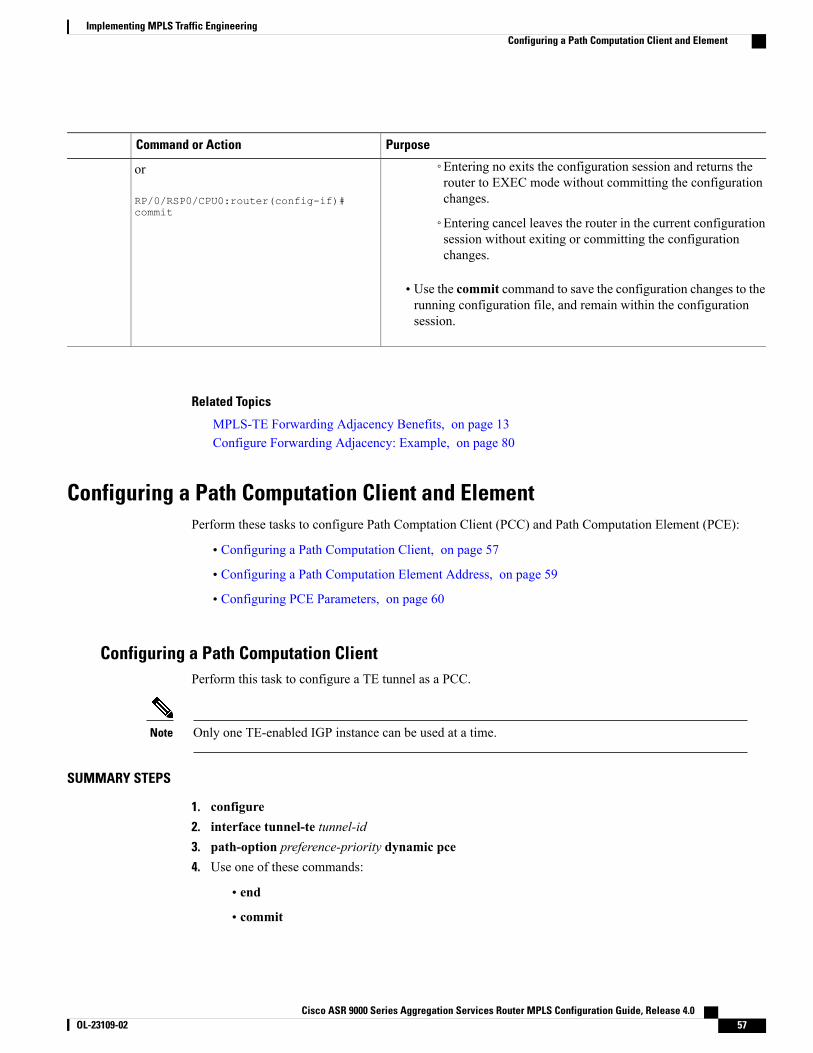
PurposeCommand or Action
or
RP/0/RSP0/CPU0:router(config-if)#commit
◦Entering no exits the configuration session and returns therouter to EXEC mode without committing the configurationchanges.
◦Entering cancel leaves the router in the current configurationsession without exiting or committing the configurationchanges.
• Use the commit command to save the configuration changes to therunning configuration file, and remain within the configurationsession.
Related Topics
MPLS-TE Forwarding Adjacency Benefits, on page 13Configure Forwarding Adjacency: Example, on page 80
Configuring a Path Computation Client and ElementPerform these tasks to configure Path Comptation Client (PCC) and Path Computation Element (PCE):
• Configuring a Path Computation Client, on page 57
• Configuring a Path Computation Element Address, on page 59
• Configuring PCE Parameters, on page 60
Configuring a Path Computation ClientPerform this task to configure a TE tunnel as a PCC.
Only one TE-enabled IGP instance can be used at a time.Note
SUMMARY STEPS
1. configure2. interface tunnel-te tunnel-id3. path-option preference-priority dynamic pce4. Use one of these commands:
• end
• commit
Cisco ASR 9000 Series Aggregation Services Router MPLS Configuration Guide, Release 4.0 OL-23109-02 57
Implementing MPLS Traffic EngineeringConfiguring a Path Computation Client and Element
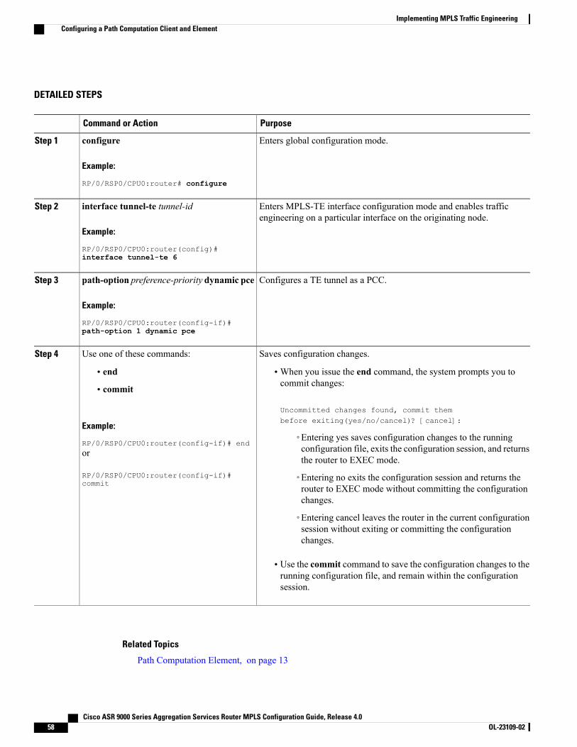
DETAILED STEPS
PurposeCommand or Action
Enters global configuration mode.configure
Example:
RP/0/RSP0/CPU0:router# configure
Step 1
Enters MPLS-TE interface configuration mode and enables trafficengineering on a particular interface on the originating node.
interface tunnel-te tunnel-id
Example:
RP/0/RSP0/CPU0:router(config)#
Step 2
interface tunnel-te 6
Configures a TE tunnel as a PCC.path-option preference-priority dynamic pce
Example:
RP/0/RSP0/CPU0:router(config-if)#
Step 3
path-option 1 dynamic pce
Saves configuration changes.Use one of these commands:Step 4
• end •When you issue the end command, the system prompts you tocommit changes:
Uncommitted changes found, commit thembefore exiting(yes/no/cancel)? [cancel]:
• commit
Example:
RP/0/RSP0/CPU0:router(config-if)# end◦Entering yes saves configuration changes to the runningconfiguration file, exits the configuration session, and returnsthe router to EXEC mode.
or
RP/0/RSP0/CPU0:router(config-if)#commit
◦Entering no exits the configuration session and returns therouter to EXEC mode without committing the configurationchanges.
◦Entering cancel leaves the router in the current configurationsession without exiting or committing the configurationchanges.
• Use the commit command to save the configuration changes to therunning configuration file, and remain within the configurationsession.
Related Topics
Path Computation Element, on page 13
Cisco ASR 9000 Series Aggregation Services Router MPLS Configuration Guide, Release 4.058 OL-23109-02
Implementing MPLS Traffic EngineeringConfiguring a Path Computation Client and Element
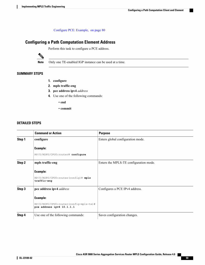
Configure PCE: Example, on page 80
Configuring a Path Computation Element AddressPerform this task to configure a PCE address.
Only one TE-enabled IGP instance can be used at a time.Note
SUMMARY STEPS
1. configure2. mpls traffic-eng3. pce address ipv4 address4. Use one of the following commands:
• end
• commit
DETAILED STEPS
PurposeCommand or Action
Enters global configuration mode.configure
Example:
RP/0/RSP0/CPU0:router# configure
Step 1
Enters the MPLS-TE configuration mode.mpls traffic-eng
Example:
RP/0/RSP0/CPU0:router(config)# mpls
Step 2
traffic-eng
Configures a PCE IPv4 address.pce address ipv4 address
Example:
RP/0/RSP0/CPU0:router(config-mpls-te)#
Step 3
pce address ipv4 10.1.1.1
Saves configuration changes.Use one of the following commands:Step 4
Cisco ASR 9000 Series Aggregation Services Router MPLS Configuration Guide, Release 4.0 OL-23109-02 59
Implementing MPLS Traffic EngineeringConfiguring a Path Computation Client and Element
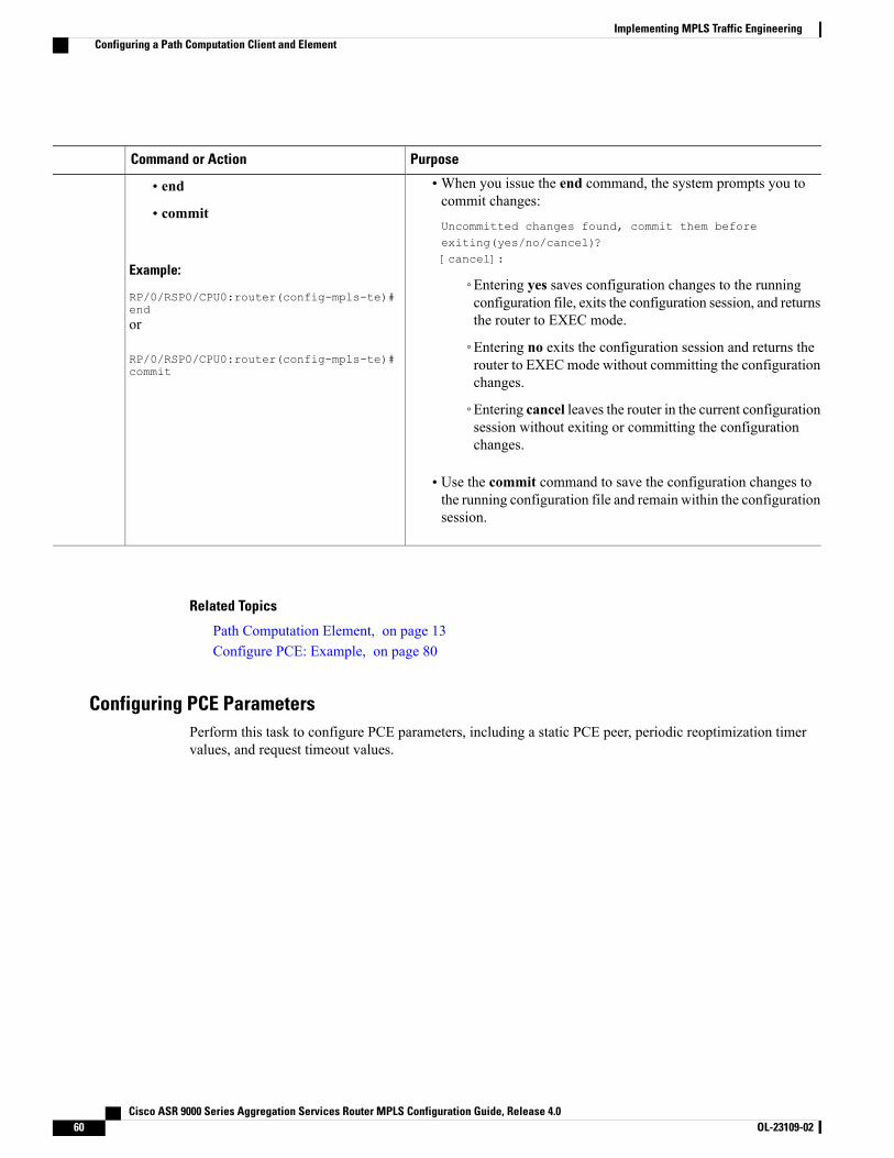
PurposeCommand or Action
•When you issue the end command, the system prompts you tocommit changes:
Uncommitted changes found, commit them beforeexiting(yes/no/cancel)?[cancel]:
• end
• commit
Example:
RP/0/RSP0/CPU0:router(config-mpls-te)#end
◦Entering yes saves configuration changes to the runningconfiguration file, exits the configuration session, and returnsthe router to EXEC mode.or
RP/0/RSP0/CPU0:router(config-mpls-te)#commit
◦Entering no exits the configuration session and returns therouter to EXECmode without committing the configurationchanges.
◦Entering cancel leaves the router in the current configurationsession without exiting or committing the configurationchanges.
• Use the commit command to save the configuration changes tothe running configuration file and remain within the configurationsession.
Related Topics
Path Computation Element, on page 13Configure PCE: Example, on page 80
Configuring PCE ParametersPerform this task to configure PCE parameters, including a static PCE peer, periodic reoptimization timervalues, and request timeout values.
Cisco ASR 9000 Series Aggregation Services Router MPLS Configuration Guide, Release 4.060 OL-23109-02
Implementing MPLS Traffic EngineeringConfiguring a Path Computation Client and Element
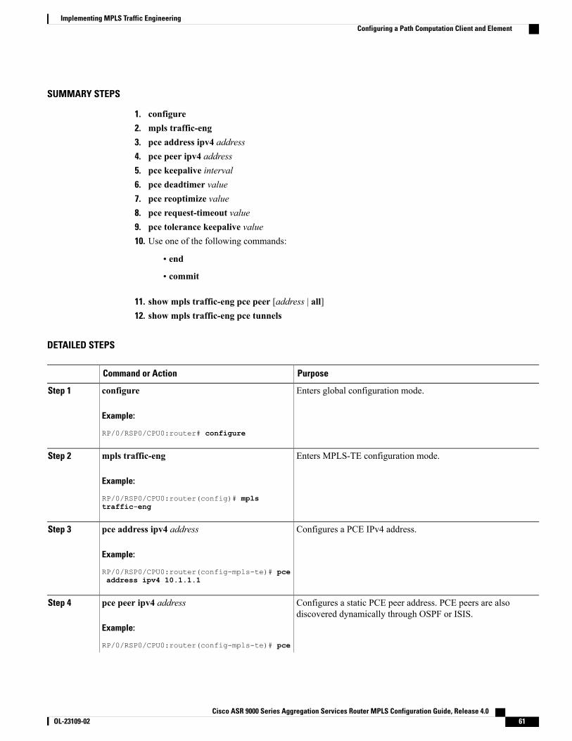
SUMMARY STEPS
1. configure2. mpls traffic-eng3. pce address ipv4 address4. pce peer ipv4 address5. pce keepalive interval6. pce deadtimer value7. pce reoptimize value8. pce request-timeout value9. pce tolerance keepalive value10. Use one of the following commands:
• end
• commit
11. show mpls traffic-eng pce peer [address | all]12. show mpls traffic-eng pce tunnels
DETAILED STEPS
PurposeCommand or Action
Enters global configuration mode.configure
Example:
RP/0/RSP0/CPU0:router# configure
Step 1
Enters MPLS-TE configuration mode.mpls traffic-eng
Example:
RP/0/RSP0/CPU0:router(config)# mpls
Step 2
traffic-eng
Configures a PCE IPv4 address.pce address ipv4 address
Example:
RP/0/RSP0/CPU0:router(config-mpls-te)# pce
Step 3
address ipv4 10.1.1.1
Configures a static PCE peer address. PCE peers are alsodiscovered dynamically through OSPF or ISIS.
pce peer ipv4 address
Example:
RP/0/RSP0/CPU0:router(config-mpls-te)# pce
Step 4
Cisco ASR 9000 Series Aggregation Services Router MPLS Configuration Guide, Release 4.0 OL-23109-02 61
Implementing MPLS Traffic EngineeringConfiguring a Path Computation Client and Element
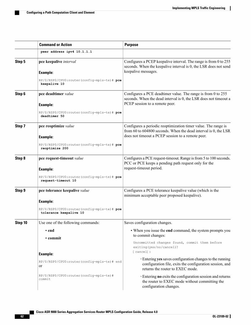
PurposeCommand or Action
peer address ipv4 10.1.1.1
Configures a PCEP keepalive interval. The range is from 0 to 255seconds. When the keepalive interval is 0, the LSR does not sendkeepalive messages.
pce keepalive interval
Example:
RP/0/RSP0/CPU0:router(config-mpls-te)# pce
Step 5
keepalive 10
Configures a PCE deadtimer value. The range is from 0 to 255seconds. When the dead interval is 0, the LSR does not timeout aPCEP session to a remote peer.
pce deadtimer value
Example:
RP/0/RSP0/CPU0:router(config-mpls-te)# pce
Step 6
deadtimer 50
Configures a periodic reoptimization timer value. The range isfrom 60 to 604800 seconds. When the dead interval is 0, the LSRdoes not timeout a PCEP session to a remote peer.
pce reoptimize value
Example:
RP/0/RSP0/CPU0:router(config-mpls-te)# pce
Step 7
reoptimize 200
Configures a PCE request-timeout. Range is from 5 to 100 seconds.PCC or PCE keeps a pending path request only for therequest-timeout period.
pce request-timeout value
Example:
RP/0/RSP0/CPU0:router(config-mpls-te)# pce
Step 8
request-timeout 10
Configures a PCE tolerance keepalive value (which is theminimum acceptable peer proposed keepalive).
pce tolerance keepalive value
Example:
RP/0/RSP0/CPU0:router(config-mpls-te)# pce
Step 9
tolerance keepalive 10
Saves configuration changes.Use one of the following commands:Step 10
• end •When you issue the end command, the system prompts youto commit changes:
Uncommitted changes found, commit them beforeexiting(yes/no/cancel)?[cancel]:
• commit
Example:
RP/0/RSP0/CPU0:router(config-mpls-te)# end◦Entering yes saves configuration changes to the runningconfiguration file, exits the configuration session, andreturns the router to EXEC mode.
or
RP/0/RSP0/CPU0:router(config-mpls-te)#commit
◦Entering no exits the configuration session and returnsthe router to EXEC mode without committing theconfiguration changes.
Cisco ASR 9000 Series Aggregation Services Router MPLS Configuration Guide, Release 4.062 OL-23109-02
Implementing MPLS Traffic EngineeringConfiguring a Path Computation Client and Element
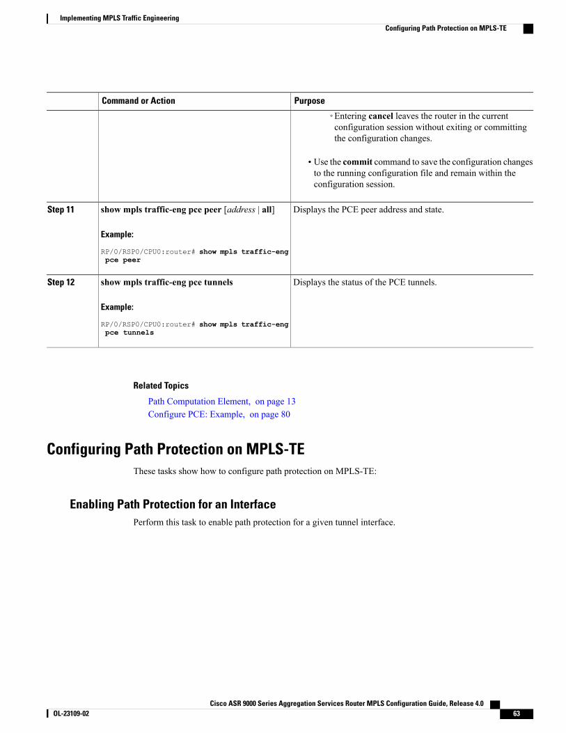
PurposeCommand or Action
◦Entering cancel leaves the router in the currentconfiguration session without exiting or committingthe configuration changes.
• Use the commit command to save the configuration changesto the running configuration file and remain within theconfiguration session.
Displays the PCE peer address and state.show mpls traffic-eng pce peer [address | all]
Example:
RP/0/RSP0/CPU0:router# show mpls traffic-eng
Step 11
pce peer
Displays the status of the PCE tunnels.show mpls traffic-eng pce tunnels
Example:
RP/0/RSP0/CPU0:router# show mpls traffic-eng
Step 12
pce tunnels
Related Topics
Path Computation Element, on page 13Configure PCE: Example, on page 80
Configuring Path Protection on MPLS-TEThese tasks show how to configure path protection on MPLS-TE:
Enabling Path Protection for an InterfacePerform this task to enable path protection for a given tunnel interface.
Cisco ASR 9000 Series Aggregation Services Router MPLS Configuration Guide, Release 4.0 OL-23109-02 63
Implementing MPLS Traffic EngineeringConfiguring Path Protection on MPLS-TE
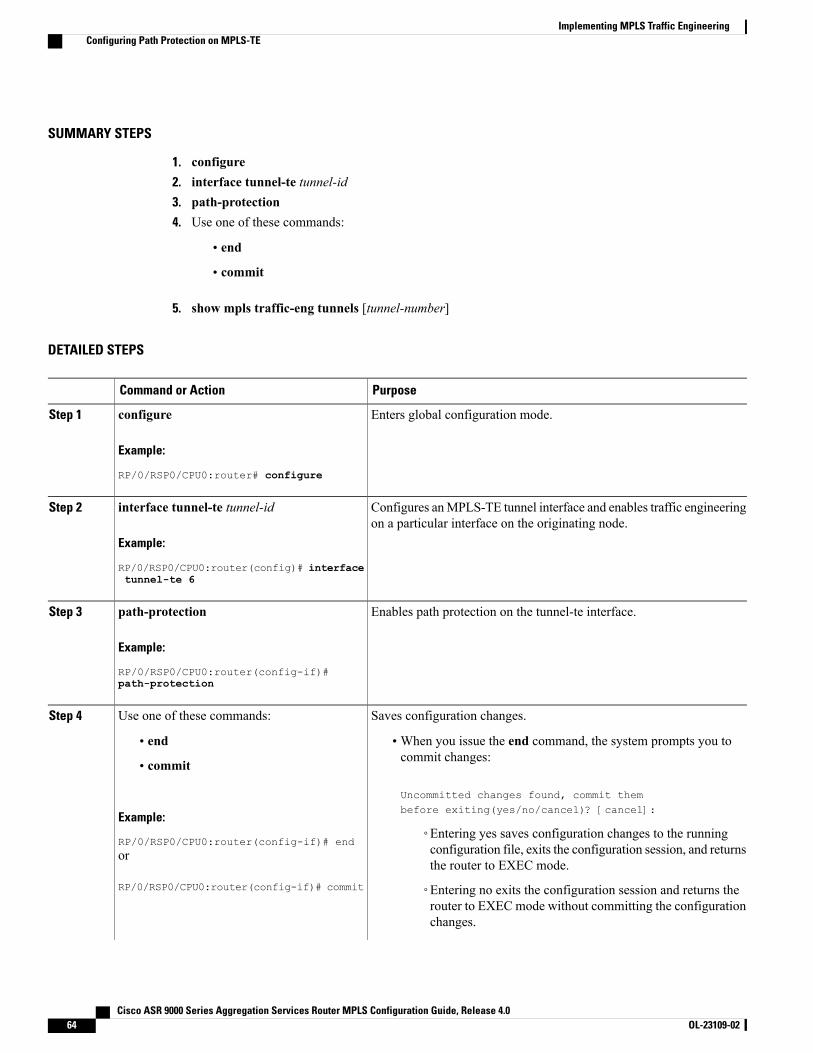
SUMMARY STEPS
1. configure2. interface tunnel-te tunnel-id3. path-protection4. Use one of these commands:
• end
• commit
5. show mpls traffic-eng tunnels [tunnel-number]
DETAILED STEPS
PurposeCommand or Action
Enters global configuration mode.configure
Example:
RP/0/RSP0/CPU0:router# configure
Step 1
Configures anMPLS-TE tunnel interface and enables traffic engineeringon a particular interface on the originating node.
interface tunnel-te tunnel-id
Example:
RP/0/RSP0/CPU0:router(config)# interface
Step 2
tunnel-te 6
Enables path protection on the tunnel-te interface.path-protection
Example:
RP/0/RSP0/CPU0:router(config-if)#
Step 3
path-protection
Saves configuration changes.Use one of these commands:Step 4
• end •When you issue the end command, the system prompts you tocommit changes:
Uncommitted changes found, commit thembefore exiting(yes/no/cancel)? [cancel]:
• commit
Example:
RP/0/RSP0/CPU0:router(config-if)# end◦Entering yes saves configuration changes to the runningconfiguration file, exits the configuration session, and returnsthe router to EXEC mode.
or
RP/0/RSP0/CPU0:router(config-if)# commit ◦Entering no exits the configuration session and returns therouter to EXEC mode without committing the configurationchanges.
Cisco ASR 9000 Series Aggregation Services Router MPLS Configuration Guide, Release 4.064 OL-23109-02
Implementing MPLS Traffic EngineeringConfiguring Path Protection on MPLS-TE
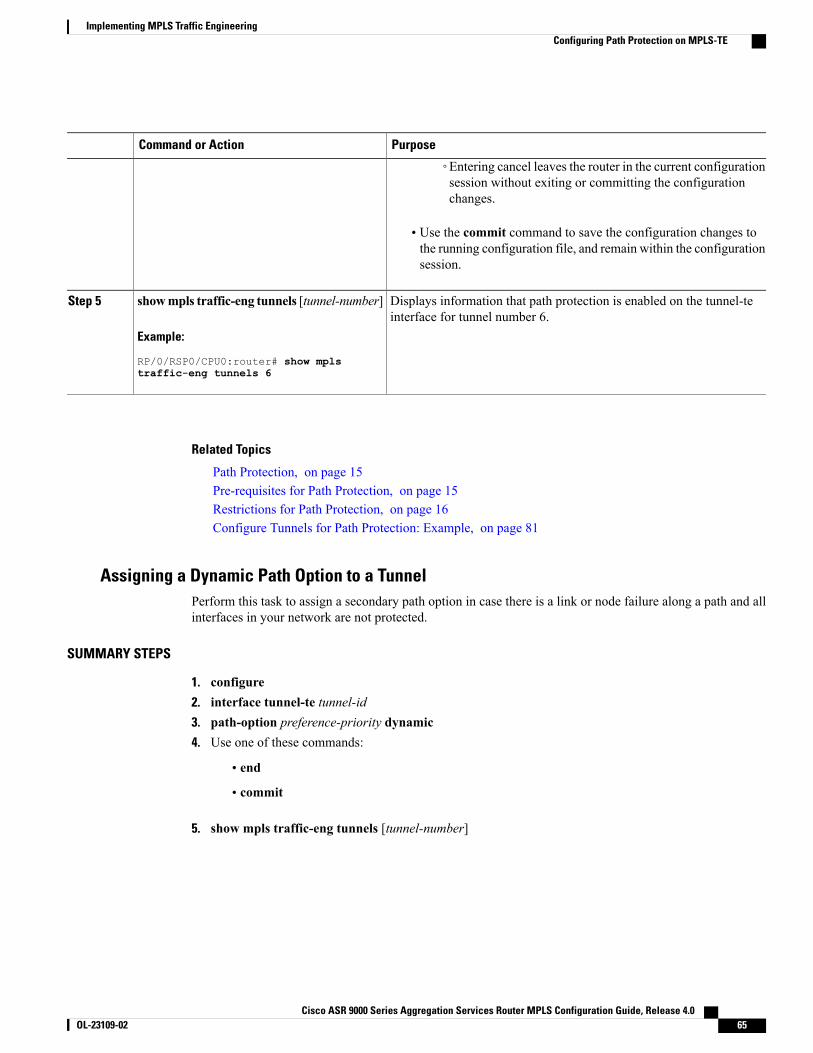
PurposeCommand or Action
◦Entering cancel leaves the router in the current configurationsession without exiting or committing the configurationchanges.
• Use the commit command to save the configuration changes tothe running configuration file, and remain within the configurationsession.
Displays information that path protection is enabled on the tunnel-teinterface for tunnel number 6.
showmpls traffic-eng tunnels [tunnel-number]
Example:
RP/0/RSP0/CPU0:router# show mpls
Step 5
traffic-eng tunnels 6
Related Topics
Path Protection, on page 15Pre-requisites for Path Protection, on page 15Restrictions for Path Protection, on page 16Configure Tunnels for Path Protection: Example, on page 81
Assigning a Dynamic Path Option to a TunnelPerform this task to assign a secondary path option in case there is a link or node failure along a path and allinterfaces in your network are not protected.
SUMMARY STEPS
1. configure2. interface tunnel-te tunnel-id3. path-option preference-priority dynamic4. Use one of these commands:
• end
• commit
5. show mpls traffic-eng tunnels [tunnel-number]
Cisco ASR 9000 Series Aggregation Services Router MPLS Configuration Guide, Release 4.0 OL-23109-02 65
Implementing MPLS Traffic EngineeringConfiguring Path Protection on MPLS-TE
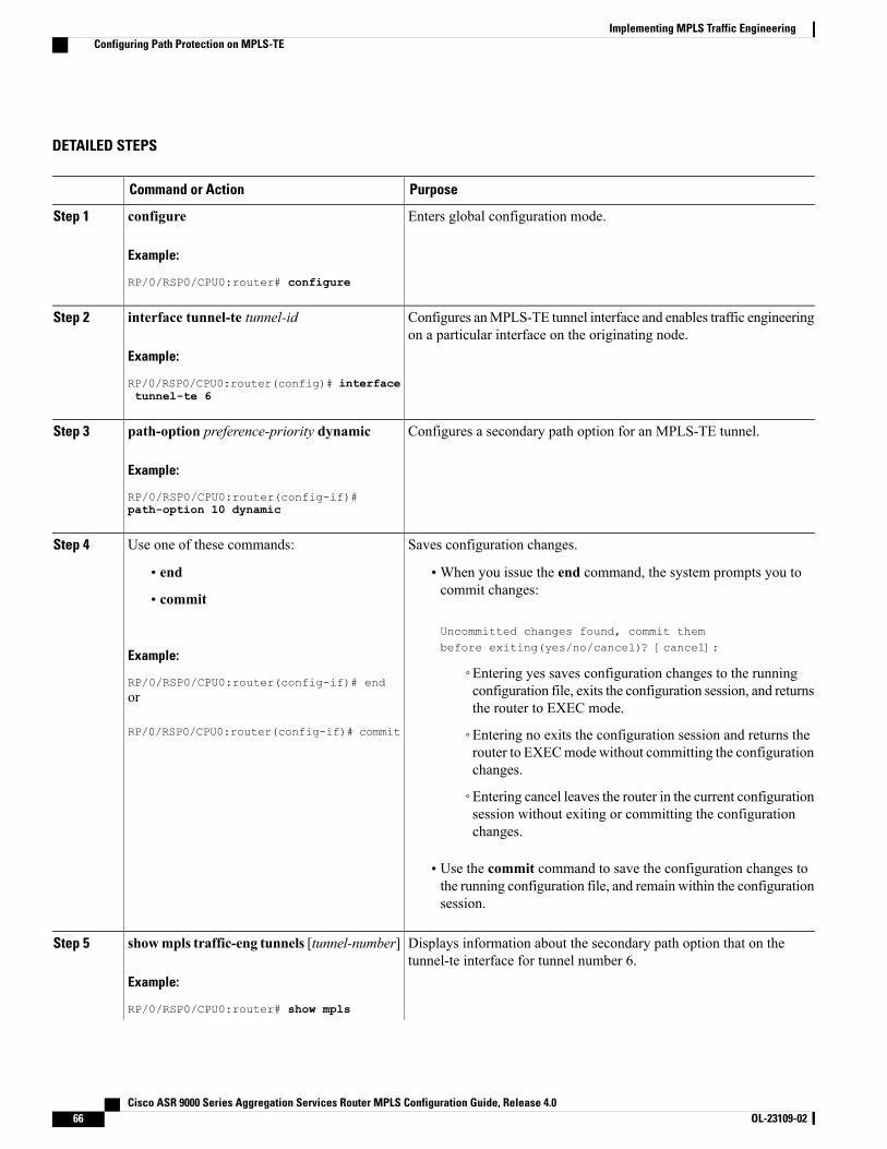
DETAILED STEPS
PurposeCommand or Action
Enters global configuration mode.configure
Example:
RP/0/RSP0/CPU0:router# configure
Step 1
Configures anMPLS-TE tunnel interface and enables traffic engineeringon a particular interface on the originating node.
interface tunnel-te tunnel-id
Example:
RP/0/RSP0/CPU0:router(config)# interface
Step 2
tunnel-te 6
Configures a secondary path option for an MPLS-TE tunnel.path-option preference-priority dynamic
Example:
RP/0/RSP0/CPU0:router(config-if)#
Step 3
path-option 10 dynamic
Saves configuration changes.Use one of these commands:Step 4
• end •When you issue the end command, the system prompts you tocommit changes:
Uncommitted changes found, commit thembefore exiting(yes/no/cancel)? [cancel]:
• commit
Example:
RP/0/RSP0/CPU0:router(config-if)# end◦Entering yes saves configuration changes to the runningconfiguration file, exits the configuration session, and returnsthe router to EXEC mode.
or
RP/0/RSP0/CPU0:router(config-if)# commit ◦Entering no exits the configuration session and returns therouter to EXECmodewithout committing the configurationchanges.
◦Entering cancel leaves the router in the current configurationsession without exiting or committing the configurationchanges.
• Use the commit command to save the configuration changes tothe running configuration file, and remain within the configurationsession.
Displays information about the secondary path option that on thetunnel-te interface for tunnel number 6.
showmpls traffic-eng tunnels [tunnel-number]
Example:
RP/0/RSP0/CPU0:router# show mpls
Step 5
Cisco ASR 9000 Series Aggregation Services Router MPLS Configuration Guide, Release 4.066 OL-23109-02
Implementing MPLS Traffic EngineeringConfiguring Path Protection on MPLS-TE
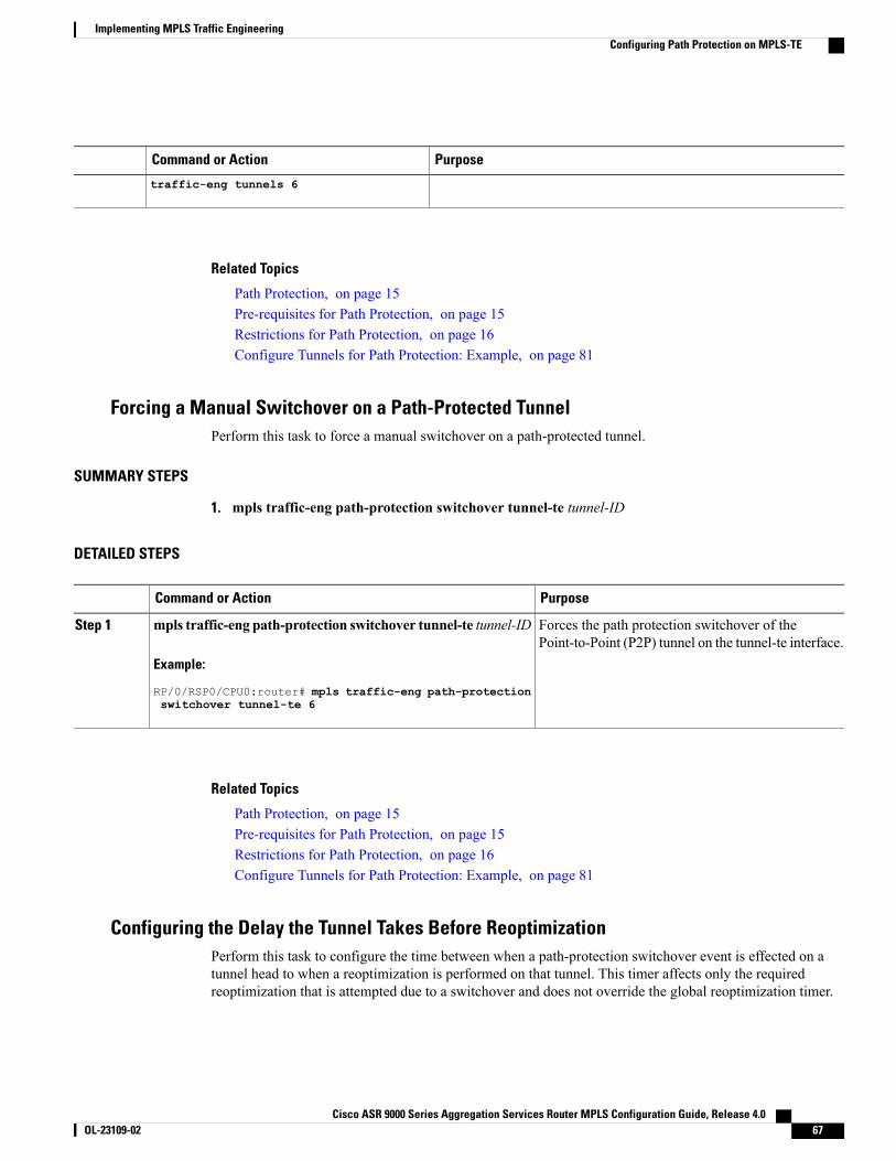
PurposeCommand or Action
traffic-eng tunnels 6
Related Topics
Path Protection, on page 15Pre-requisites for Path Protection, on page 15Restrictions for Path Protection, on page 16Configure Tunnels for Path Protection: Example, on page 81
Forcing a Manual Switchover on a Path-Protected TunnelPerform this task to force a manual switchover on a path-protected tunnel.
SUMMARY STEPS
1. mpls traffic-eng path-protection switchover tunnel-te tunnel-ID
DETAILED STEPS
PurposeCommand or Action
Forces the path protection switchover of thePoint-to-Point (P2P) tunnel on the tunnel-te interface.
mpls traffic-eng path-protection switchover tunnel-te tunnel-ID
Example:
RP/0/RSP0/CPU0:router# mpls traffic-eng path-protection
Step 1
switchover tunnel-te 6
Related Topics
Path Protection, on page 15Pre-requisites for Path Protection, on page 15Restrictions for Path Protection, on page 16Configure Tunnels for Path Protection: Example, on page 81
Configuring the Delay the Tunnel Takes Before ReoptimizationPerform this task to configure the time between when a path-protection switchover event is effected on atunnel head to when a reoptimization is performed on that tunnel. This timer affects only the requiredreoptimization that is attempted due to a switchover and does not override the global reoptimization timer.
Cisco ASR 9000 Series Aggregation Services Router MPLS Configuration Guide, Release 4.0 OL-23109-02 67
Implementing MPLS Traffic EngineeringConfiguring Path Protection on MPLS-TE
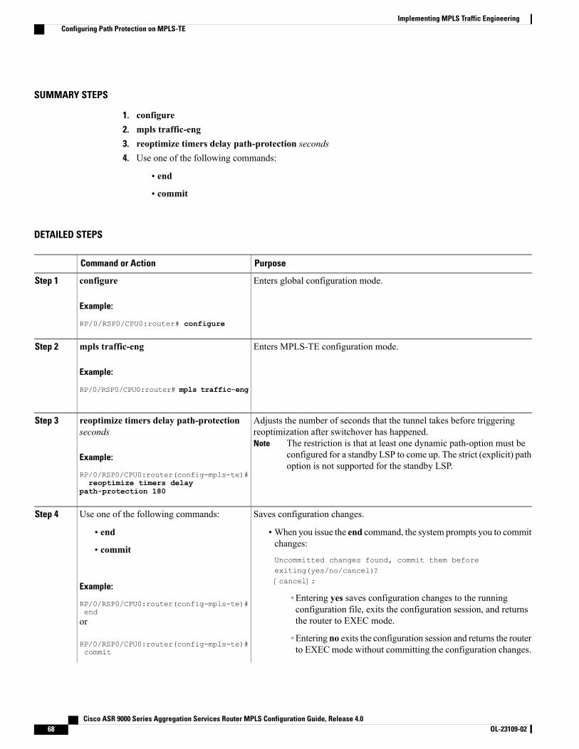
SUMMARY STEPS
1. configure2. mpls traffic-eng3. reoptimize timers delay path-protection seconds4. Use one of the following commands:
• end
• commit
DETAILED STEPS
PurposeCommand or Action
Enters global configuration mode.configure
Example:
RP/0/RSP0/CPU0:router# configure
Step 1
Enters MPLS-TE configuration mode.mpls traffic-eng
Example:
RP/0/RSP0/CPU0:router# mpls traffic-eng
Step 2
Adjusts the number of seconds that the tunnel takes before triggeringreoptimization after switchover has happened.
The restriction is that at least one dynamic path-option must beconfigured for a standby LSP to come up. The strict (explicit) pathoption is not supported for the standby LSP.
Note
reoptimize timers delay path-protectionseconds
Example:
RP/0/RSP0/CPU0:router(config-mpls-te)#
Step 3
reoptimize timers delaypath-protection 180
Saves configuration changes.Use one of the following commands:Step 4
• end •When you issue the end command, the system prompts you to commitchanges:
Uncommitted changes found, commit them beforeexiting(yes/no/cancel)?[cancel]:
• commit
Example:
RP/0/RSP0/CPU0:router(config-mpls-te)#end
◦Entering yes saves configuration changes to the runningconfiguration file, exits the configuration session, and returnsthe router to EXEC mode.or
RP/0/RSP0/CPU0:router(config-mpls-te)#commit
◦Entering no exits the configuration session and returns the routerto EXEC mode without committing the configuration changes.
Cisco ASR 9000 Series Aggregation Services Router MPLS Configuration Guide, Release 4.068 OL-23109-02
Implementing MPLS Traffic EngineeringConfiguring Path Protection on MPLS-TE
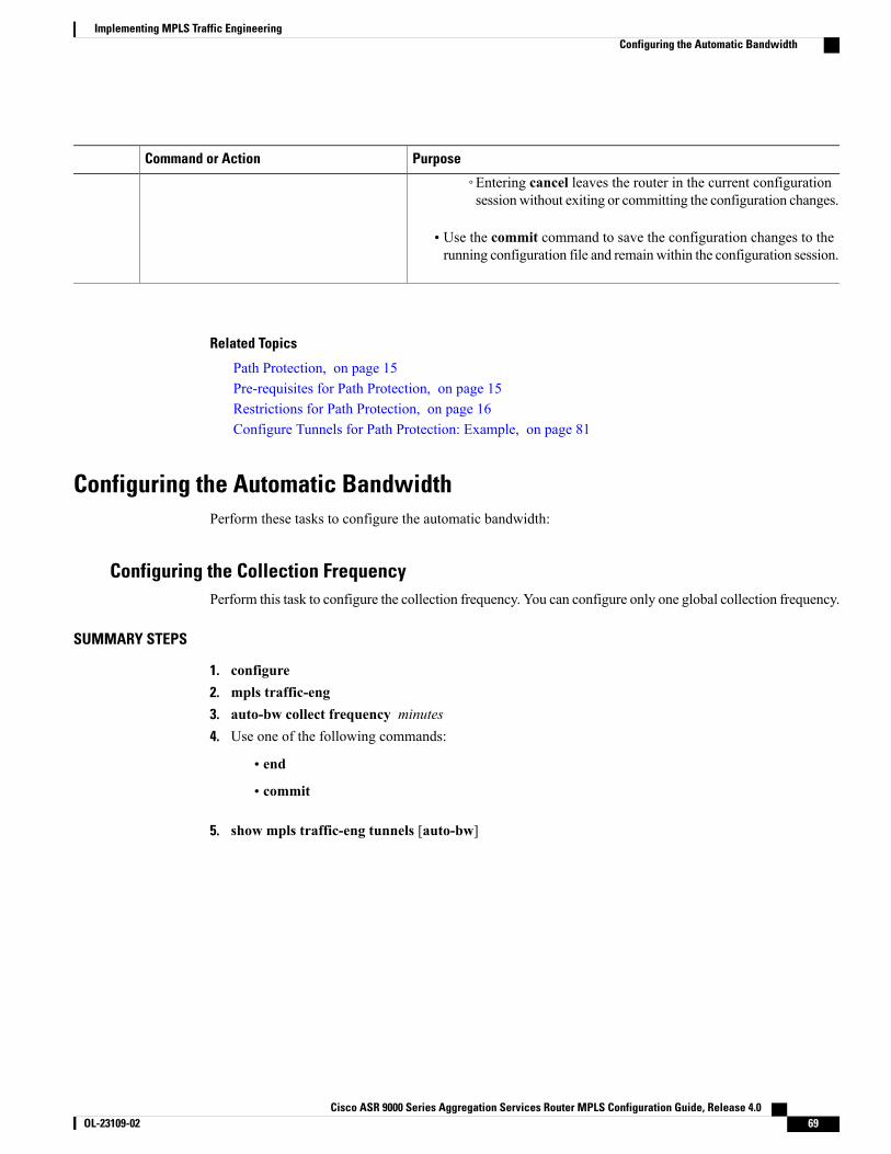
PurposeCommand or Action
◦Entering cancel leaves the router in the current configurationsessionwithout exiting or committing the configuration changes.
• Use the commit command to save the configuration changes to therunning configuration file and remainwithin the configuration session.
Related Topics
Path Protection, on page 15Pre-requisites for Path Protection, on page 15Restrictions for Path Protection, on page 16Configure Tunnels for Path Protection: Example, on page 81
Configuring the Automatic BandwidthPerform these tasks to configure the automatic bandwidth:
Configuring the Collection FrequencyPerform this task to configure the collection frequency. You can configure only one global collection frequency.
SUMMARY STEPS
1. configure2. mpls traffic-eng3. auto-bw collect frequency minutes4. Use one of the following commands:
• end
• commit
5. show mpls traffic-eng tunnels [auto-bw]
Cisco ASR 9000 Series Aggregation Services Router MPLS Configuration Guide, Release 4.0 OL-23109-02 69
Implementing MPLS Traffic EngineeringConfiguring the Automatic Bandwidth
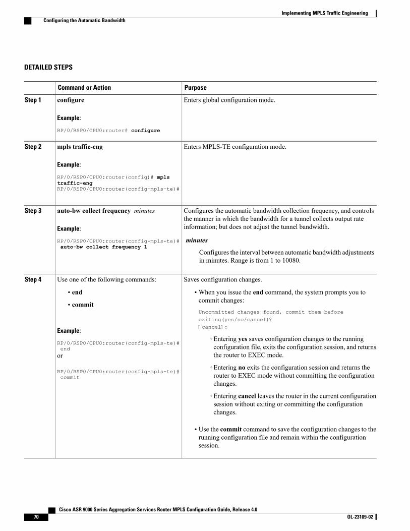
DETAILED STEPS
PurposeCommand or Action
Enters global configuration mode.configure
Example:
RP/0/RSP0/CPU0:router# configure
Step 1
Enters MPLS-TE configuration mode.mpls traffic-eng
Example:
RP/0/RSP0/CPU0:router(config)# mpls
Step 2
traffic-engRP/0/RSP0/CPU0:router(config-mpls-te)#
Configures the automatic bandwidth collection frequency, and controlsthe manner in which the bandwidth for a tunnel collects output rateinformation; but does not adjust the tunnel bandwidth.
auto-bw collect frequency minutes
Example:
RP/0/RSP0/CPU0:router(config-mpls-te)#
Step 3
minutesauto-bw collect frequency 1
Configures the interval between automatic bandwidth adjustmentsin minutes. Range is from 1 to 10080.
Saves configuration changes.Use one of the following commands:Step 4
• end •When you issue the end command, the system prompts you tocommit changes:
Uncommitted changes found, commit them beforeexiting(yes/no/cancel)?[cancel]:
• commit
Example:
RP/0/RSP0/CPU0:router(config-mpls-te)#end
◦Entering yes saves configuration changes to the runningconfiguration file, exits the configuration session, and returnsthe router to EXEC mode.or
RP/0/RSP0/CPU0:router(config-mpls-te)#commit
◦Entering no exits the configuration session and returns therouter to EXEC mode without committing the configurationchanges.
◦Entering cancel leaves the router in the current configurationsession without exiting or committing the configurationchanges.
• Use the commit command to save the configuration changes to therunning configuration file and remain within the configurationsession.
Cisco ASR 9000 Series Aggregation Services Router MPLS Configuration Guide, Release 4.070 OL-23109-02
Implementing MPLS Traffic EngineeringConfiguring the Automatic Bandwidth
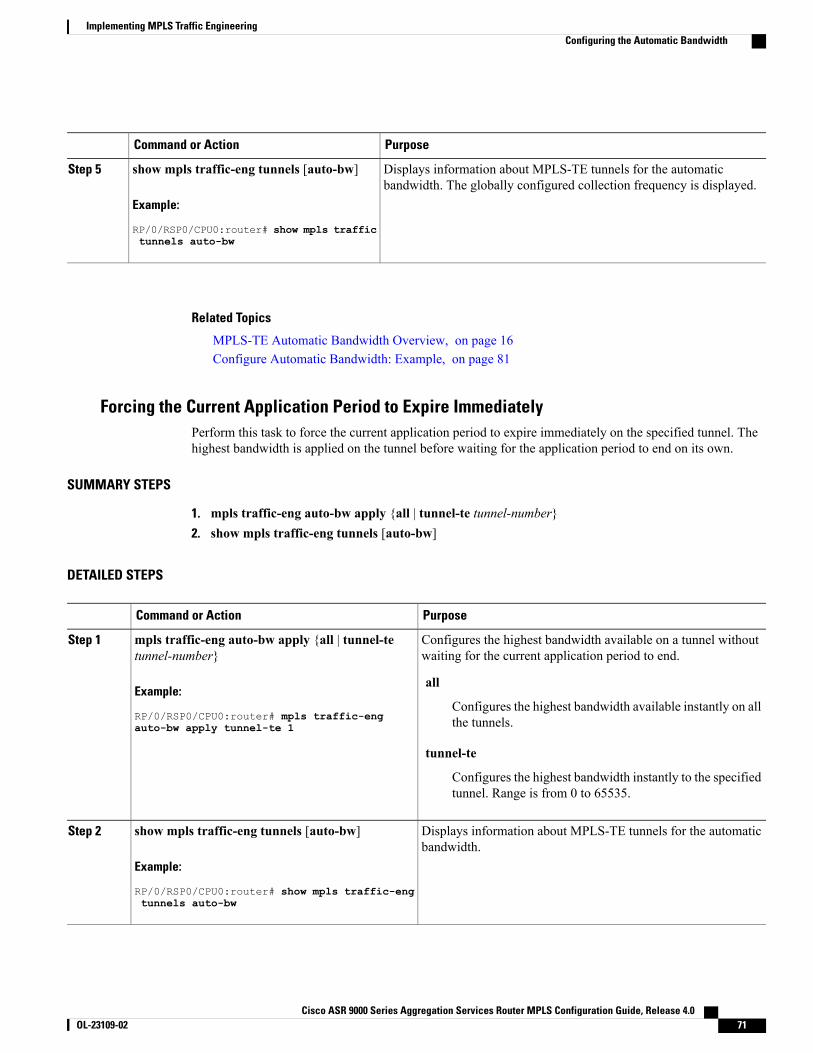
PurposeCommand or Action
Displays information about MPLS-TE tunnels for the automaticbandwidth. The globally configured collection frequency is displayed.
show mpls traffic-eng tunnels [auto-bw]
Example:
RP/0/RSP0/CPU0:router# show mpls traffic
Step 5
tunnels auto-bw
Related Topics
MPLS-TE Automatic Bandwidth Overview, on page 16Configure Automatic Bandwidth: Example, on page 81
Forcing the Current Application Period to Expire ImmediatelyPerform this task to force the current application period to expire immediately on the specified tunnel. Thehighest bandwidth is applied on the tunnel before waiting for the application period to end on its own.
SUMMARY STEPS
1. mpls traffic-eng auto-bw apply {all | tunnel-te tunnel-number}2. show mpls traffic-eng tunnels [auto-bw]
DETAILED STEPS
PurposeCommand or Action
Configures the highest bandwidth available on a tunnel withoutwaiting for the current application period to end.
mpls traffic-eng auto-bw apply {all | tunnel-tetunnel-number}
Example:
RP/0/RSP0/CPU0:router# mpls traffic-eng
Step 1
all
Configures the highest bandwidth available instantly on allthe tunnels.auto-bw apply tunnel-te 1
tunnel-te
Configures the highest bandwidth instantly to the specifiedtunnel. Range is from 0 to 65535.
Displays information about MPLS-TE tunnels for the automaticbandwidth.
show mpls traffic-eng tunnels [auto-bw]
Example:
RP/0/RSP0/CPU0:router# show mpls traffic-eng
Step 2
tunnels auto-bw
Cisco ASR 9000 Series Aggregation Services Router MPLS Configuration Guide, Release 4.0 OL-23109-02 71
Implementing MPLS Traffic EngineeringConfiguring the Automatic Bandwidth
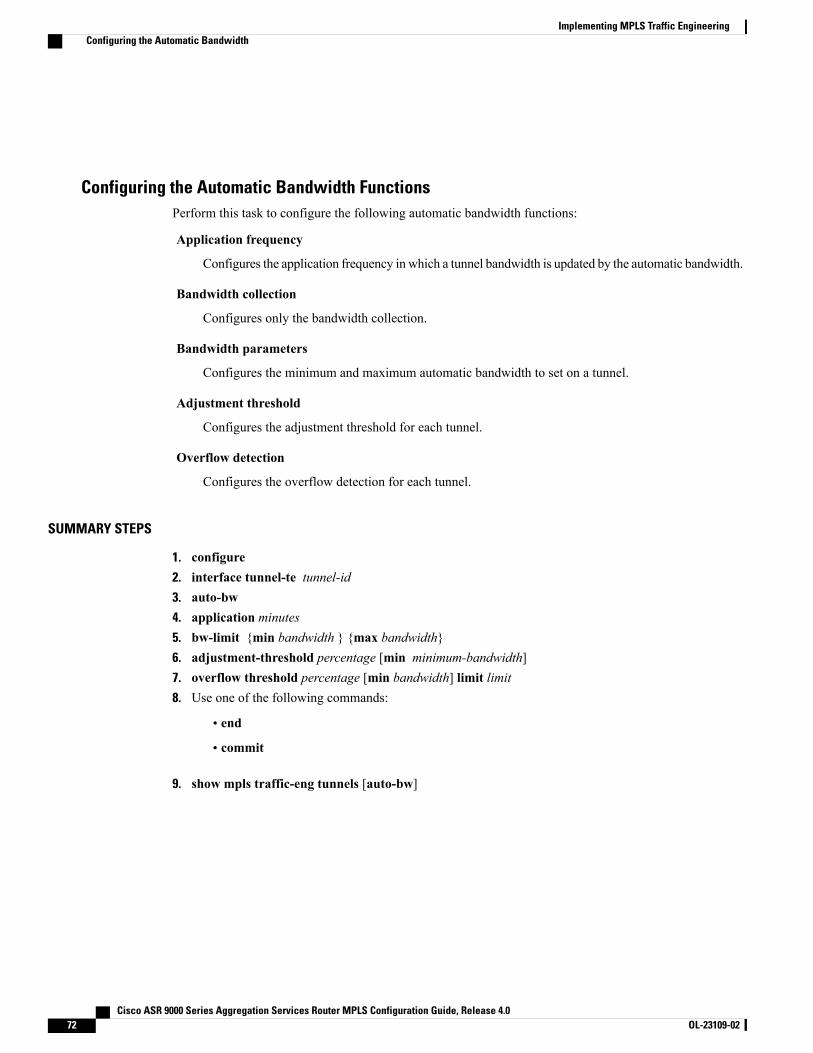
Configuring the Automatic Bandwidth FunctionsPerform this task to configure the following automatic bandwidth functions:
Application frequency
Configures the application frequency in which a tunnel bandwidth is updated by the automatic bandwidth.
Bandwidth collection
Configures only the bandwidth collection.
Bandwidth parameters
Configures the minimum and maximum automatic bandwidth to set on a tunnel.
Adjustment threshold
Configures the adjustment threshold for each tunnel.
Overflow detection
Configures the overflow detection for each tunnel.
SUMMARY STEPS
1. configure2. interface tunnel-te tunnel-id3. auto-bw4. application minutes5. bw-limit {min bandwidth } {max bandwidth}6. adjustment-threshold percentage [min minimum-bandwidth]7. overflow threshold percentage [min bandwidth] limit limit8. Use one of the following commands:
• end
• commit
9. show mpls traffic-eng tunnels [auto-bw]
Cisco ASR 9000 Series Aggregation Services Router MPLS Configuration Guide, Release 4.072 OL-23109-02
Implementing MPLS Traffic EngineeringConfiguring the Automatic Bandwidth
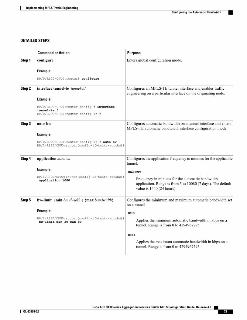
DETAILED STEPS
PurposeCommand or Action
Enters global configuration mode.configure
Example:
RP/0/RSP0/CPU0:router# configure
Step 1
Configures an MPLS-TE tunnel interface and enables trafficengineering on a particular interface on the originating node.
interface tunnel-te tunnel-id
Example:
RP/0/RSP0/CPU0:router(config)# interface
Step 2
tunnel-te 6RP/0/RSP0/CPU0:router(config-if)#
Configures automatic bandwidth on a tunnel interface and entersMPLS-TE automatic bandwidth interface configuration mode.
auto-bw
Example:
RP/0/RSP0/CPU0:router(config-if)# auto-bw
Step 3
RP/0/RSP0/CPU0:router(config-if-tunte-autobw)#
Configures the application frequency in minutes for the applicabletunnel.
application minutes
Example:
RP/0/RSP0/CPU0:router(config-if-tunte-autobw)#
Step 4
minutes
Frequency in minutes for the automatic bandwidthapplication. Range is from 5 to 10080 (7 days). The defaultvalue is 1440 (24 hours).
application 1000
Configures the minimum and maximum automatic bandwidth seton a tunnel.
bw-limit {min bandwidth } {max bandwidth}
Example:
RP/0/RSP0/CPU0:router(config-if-tunte-autobw)#
Step 5
min
Applies the minimum automatic bandwidth in kbps on atunnel. Range is from 0 to 4294967295.
bw-limit min 30 max 80
max
Applies the maximum automatic bandwidth in kbps on atunnel. Range is from 0 to 4294967295.
Cisco ASR 9000 Series Aggregation Services Router MPLS Configuration Guide, Release 4.0 OL-23109-02 73
Implementing MPLS Traffic EngineeringConfiguring the Automatic Bandwidth
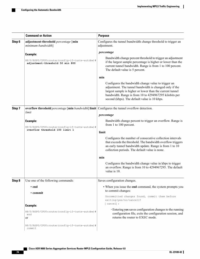
PurposeCommand or Action
Configures the tunnel bandwidth change threshold to trigger anadjustment.
adjustment-threshold percentage [minminimum-bandwidth]
Example:
RP/0/RSP0/CPU0:router(config-if-tunte-autobw)#
Step 6
percentage
Bandwidth change percent threshold to trigger an adjustmentif the largest sample percentage is higher or lower than thecurrent tunnel bandwidth. Range is from 1 to 100 percent.The default value is 5 percent.
adjustment-threshold 50 min 800
min
Configures the bandwidth change value to trigger anadjustment. The tunnel bandwidth is changed only if thelargest sample is higher or lower than the current tunnelbandwidth. Range is from 10 to 4294967295 kilobits persecond (kbps). The default value is 10 kbps.
Configures the tunnel overflow detection.overflow threshold percentage [min bandwidth] limitlimit
Step 7
percentage
Example:
RP/0/RSP0/CPU0:router(config-if-tunte-autobw)#
Bandwidth change percent to trigger an overflow. Range isfrom 1 to 100 percent.
overflow threshold 100 limit 1limit
Configures the number of consecutive collection intervalsthat exceeds the threshold. The bandwidth overflow triggersan early tunnel bandwidth update. Range is from 1 to 10collection periods. The default value is none.
min
Configures the bandwidth change value in kbps to triggeran overflow. Range is from 10 to 4294967295. The defaultvalue is 10.
Saves configuration changes.Use one of the following commands:Step 8
• end •When you issue the end command, the system prompts youto commit changes:
Uncommitted changes found, commit them beforeexiting(yes/no/cancel)?[cancel]:
• commit
Example:
RP/0/RSP0/CPU0:router(config-if-tunte-autobw)#end
◦Entering yes saves configuration changes to the runningconfiguration file, exits the configuration session, andreturns the router to EXEC mode.or
RP/0/RSP0/CPU0:router(config-if-tunte-autobw)#commit
Cisco ASR 9000 Series Aggregation Services Router MPLS Configuration Guide, Release 4.074 OL-23109-02
Implementing MPLS Traffic EngineeringConfiguring the Automatic Bandwidth
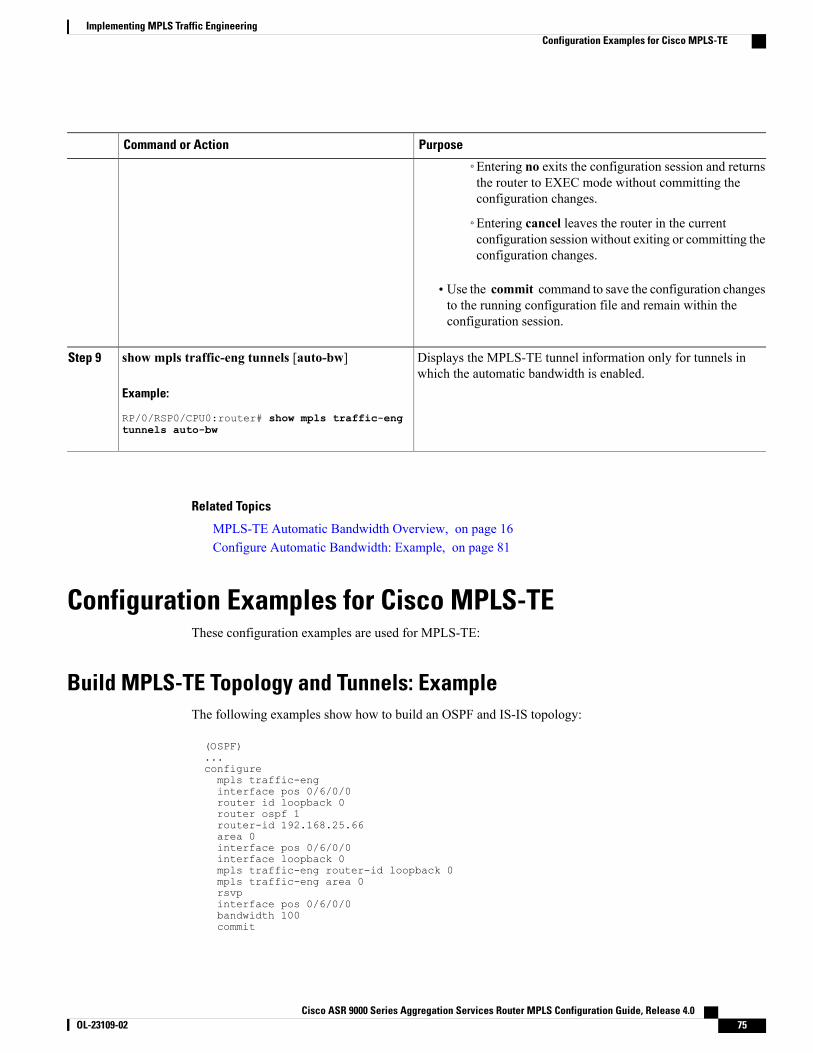
PurposeCommand or Action
◦Entering no exits the configuration session and returnsthe router to EXEC mode without committing theconfiguration changes.
◦Entering cancel leaves the router in the currentconfiguration session without exiting or committing theconfiguration changes.
• Use the commit command to save the configuration changesto the running configuration file and remain within theconfiguration session.
Displays the MPLS-TE tunnel information only for tunnels inwhich the automatic bandwidth is enabled.
show mpls traffic-eng tunnels [auto-bw]
Example:
RP/0/RSP0/CPU0:router# show mpls traffic-eng
Step 9
tunnels auto-bw
Related Topics
MPLS-TE Automatic Bandwidth Overview, on page 16Configure Automatic Bandwidth: Example, on page 81
Configuration Examples for Cisco MPLS-TEThese configuration examples are used for MPLS-TE:
Build MPLS-TE Topology and Tunnels: ExampleThe following examples show how to build an OSPF and IS-IS topology:
(OSPF)...configurempls traffic-enginterface pos 0/6/0/0router id loopback 0router ospf 1router-id 192.168.25.66area 0interface pos 0/6/0/0interface loopback 0mpls traffic-eng router-id loopback 0mpls traffic-eng area 0rsvpinterface pos 0/6/0/0bandwidth 100commit
Cisco ASR 9000 Series Aggregation Services Router MPLS Configuration Guide, Release 4.0 OL-23109-02 75
Implementing MPLS Traffic EngineeringConfiguration Examples for Cisco MPLS-TE
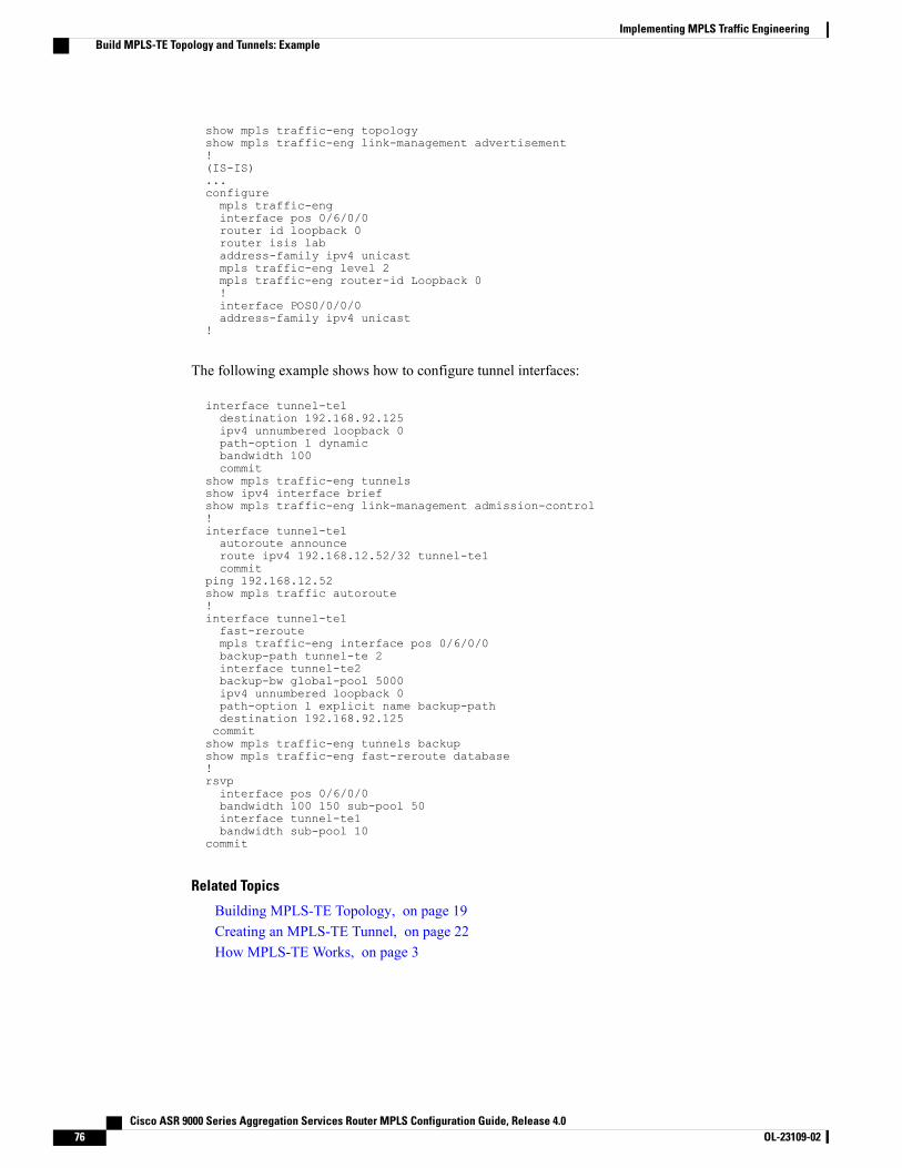
show mpls traffic-eng topologyshow mpls traffic-eng link-management advertisement!(IS-IS)...configurempls traffic-enginterface pos 0/6/0/0router id loopback 0router isis labaddress-family ipv4 unicastmpls traffic-eng level 2mpls traffic-eng router-id Loopback 0!interface POS0/0/0/0address-family ipv4 unicast
!
The following example shows how to configure tunnel interfaces:
interface tunnel-te1destination 192.168.92.125ipv4 unnumbered loopback 0path-option l dynamicbandwidth 100commit
show mpls traffic-eng tunnelsshow ipv4 interface briefshow mpls traffic-eng link-management admission-control!interface tunnel-te1autoroute announceroute ipv4 192.168.12.52/32 tunnel-te1commit
ping 192.168.12.52show mpls traffic autoroute!interface tunnel-te1fast-reroutempls traffic-eng interface pos 0/6/0/0backup-path tunnel-te 2interface tunnel-te2backup-bw global-pool 5000ipv4 unnumbered loopback 0path-option l explicit name backup-pathdestination 192.168.92.125commitshow mpls traffic-eng tunnels backupshow mpls traffic-eng fast-reroute database!rsvpinterface pos 0/6/0/0bandwidth 100 150 sub-pool 50interface tunnel-te1bandwidth sub-pool 10
commit
Related Topics
Building MPLS-TE Topology, on page 19Creating an MPLS-TE Tunnel, on page 22How MPLS-TE Works, on page 3
Cisco ASR 9000 Series Aggregation Services Router MPLS Configuration Guide, Release 4.076 OL-23109-02
Implementing MPLS Traffic EngineeringBuild MPLS-TE Topology and Tunnels: Example
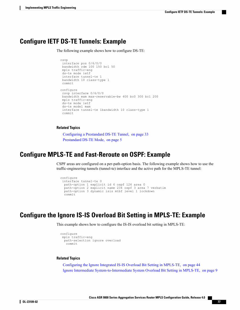
Configure IETF DS-TE Tunnels: ExampleThe following example shows how to configure DS-TE:
rsvpinterface pos 0/6/0/0bandwidth rdm 100 150 bc1 50mpls traffic-engds-te mode ietfinterface tunnel-te 1bandwidth 10 class-type 1commit
configurersvp interface 0/6/0/0bandwidth mam max-reservable-bw 400 bc0 300 bc1 200mpls traffic-engds-te mode ietfds-te model maminterface tunnel-te 1bandwidth 10 class-type 1commit
Related Topics
Configuring a Prestandard DS-TE Tunnel, on page 33Prestandard DS-TE Mode, on page 5
Configure MPLS-TE and Fast-Reroute on OSPF: ExampleCSPF areas are configured on a per-path-option basis. The following example shows how to use thetraffic-engineering tunnels (tunnel-te) interface and the active path for the MPLS-TE tunnel:
configureinterface tunnel-te 0path-option 1 explicit id 6 ospf 126 area 0path-option 2 explicit name 234 ospf 3 area 7 verbatimpath-option 3 dynamic isis mtbf level 1 lockdowncommit
Configure the Ignore IS-IS Overload Bit Setting in MPLS-TE: ExampleThis example shows how to configure the IS-IS overload bit setting in MPLS-TE:
configurempls traffic-engpath-selection ignore overloadcommit
Related Topics
Configuring the Ignore Integrated IS-IS Overload Bit Setting in MPLS-TE, on page 44Ignore Intermediate System-to-Intermediate System Overload Bit Setting in MPLS-TE, on page 9
Cisco ASR 9000 Series Aggregation Services Router MPLS Configuration Guide, Release 4.0 OL-23109-02 77
Implementing MPLS Traffic EngineeringConfigure IETF DS-TE Tunnels: Example
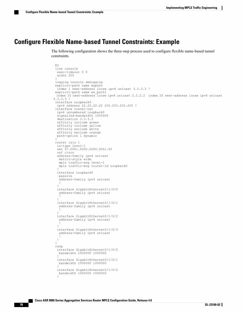
Configure Flexible Name-based Tunnel Constraints: ExampleThe following configuration shows the three-step process used to configure flexible name-based tunnelconstraints.
R2line consoleexec-timeout 0 0width 250!logging console debuggingexplicit-path name mypathindex 1 next-address loose ipv4 unicast 3.3.3.3 !explicit-path name ex_path1index 10 next-address loose ipv4 unicast 2.2.2.2 index 20 next-address loose ipv4 unicast
3.3.3.3 !interface Loopback0ipv4 address 22.22.22.22 255.255.255.255 !interface tunnel-te1ipv4 unnumbered Loopback0signalled-bandwidth 1000000destination 3.3.3.3affinity include greenaffinity include yellowaffinity exclude whiteaffinity exclude orangepath-option 1 dynamic!router isis 1is-type level-1net 47.0001.0000.0000.0001.00nsf ciscoaddress-family ipv4 unicastmetric-style widempls traffic-eng level-1mpls traffic-eng router-id Loopback0!interface Loopback0passiveaddress-family ipv4 unicast!!interface GigabitEthernet0/1/0/0address-family ipv4 unicast!!interface GigabitEthernet0/1/0/1address-family ipv4 unicast!!interface GigabitEthernet0/1/0/2address-family ipv4 unicast!!interface GigabitEthernet0/1/0/3address-family ipv4 unicast!!!rsvpinterface GigabitEthernet0/1/0/0bandwidth 1000000 1000000!interface GigabitEthernet0/1/0/1bandwidth 1000000 1000000!interface GigabitEthernet0/1/0/2bandwidth 1000000 1000000!
Cisco ASR 9000 Series Aggregation Services Router MPLS Configuration Guide, Release 4.078 OL-23109-02
Implementing MPLS Traffic EngineeringConfigure Flexible Name-based Tunnel Constraints: Example
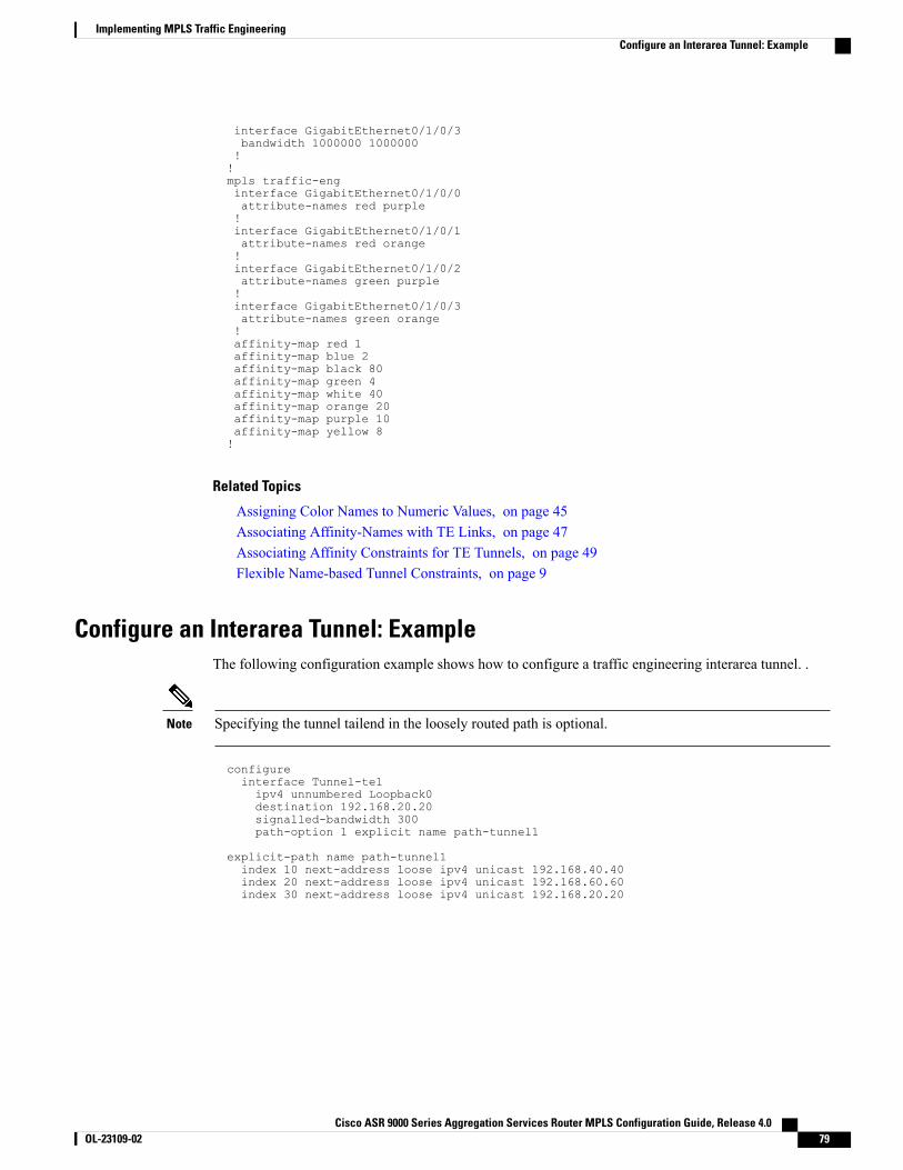
interface GigabitEthernet0/1/0/3bandwidth 1000000 1000000!!mpls traffic-enginterface GigabitEthernet0/1/0/0attribute-names red purple!interface GigabitEthernet0/1/0/1attribute-names red orange!interface GigabitEthernet0/1/0/2attribute-names green purple!interface GigabitEthernet0/1/0/3attribute-names green orange!affinity-map red 1affinity-map blue 2affinity-map black 80affinity-map green 4affinity-map white 40affinity-map orange 20affinity-map purple 10affinity-map yellow 8!
Related Topics
Assigning Color Names to Numeric Values, on page 45Associating Affinity-Names with TE Links, on page 47Associating Affinity Constraints for TE Tunnels, on page 49Flexible Name-based Tunnel Constraints, on page 9
Configure an Interarea Tunnel: ExampleThe following configuration example shows how to configure a traffic engineering interarea tunnel. .
Specifying the tunnel tailend in the loosely routed path is optional.Note
configureinterface Tunnel-te1ipv4 unnumbered Loopback0destination 192.168.20.20signalled-bandwidth 300path-option 1 explicit name path-tunnel1
explicit-path name path-tunnel1index 10 next-address loose ipv4 unicast 192.168.40.40index 20 next-address loose ipv4 unicast 192.168.60.60index 30 next-address loose ipv4 unicast 192.168.20.20
Cisco ASR 9000 Series Aggregation Services Router MPLS Configuration Guide, Release 4.0 OL-23109-02 79
Implementing MPLS Traffic EngineeringConfigure an Interarea Tunnel: Example
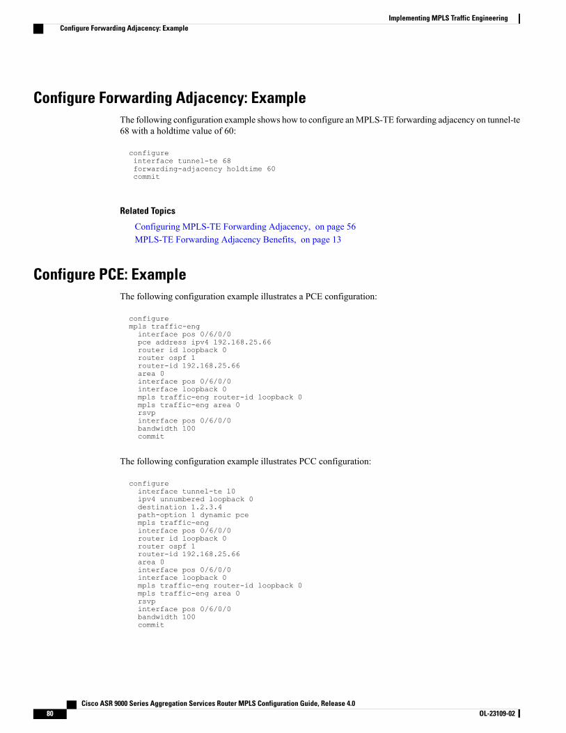
Configure Forwarding Adjacency: ExampleThe following configuration example shows how to configure anMPLS-TE forwarding adjacency on tunnel-te68 with a holdtime value of 60:
configureinterface tunnel-te 68forwarding-adjacency holdtime 60commit
Related Topics
Configuring MPLS-TE Forwarding Adjacency, on page 56MPLS-TE Forwarding Adjacency Benefits, on page 13
Configure PCE: ExampleThe following configuration example illustrates a PCE configuration:
configurempls traffic-enginterface pos 0/6/0/0pce address ipv4 192.168.25.66router id loopback 0router ospf 1router-id 192.168.25.66area 0interface pos 0/6/0/0interface loopback 0mpls traffic-eng router-id loopback 0mpls traffic-eng area 0rsvpinterface pos 0/6/0/0bandwidth 100commit
The following configuration example illustrates PCC configuration:
configureinterface tunnel-te 10ipv4 unnumbered loopback 0destination 1.2.3.4path-option 1 dynamic pcempls traffic-enginterface pos 0/6/0/0router id loopback 0router ospf 1router-id 192.168.25.66area 0interface pos 0/6/0/0interface loopback 0mpls traffic-eng router-id loopback 0mpls traffic-eng area 0rsvpinterface pos 0/6/0/0bandwidth 100commit
Cisco ASR 9000 Series Aggregation Services Router MPLS Configuration Guide, Release 4.080 OL-23109-02
Implementing MPLS Traffic EngineeringConfigure Forwarding Adjacency: Example
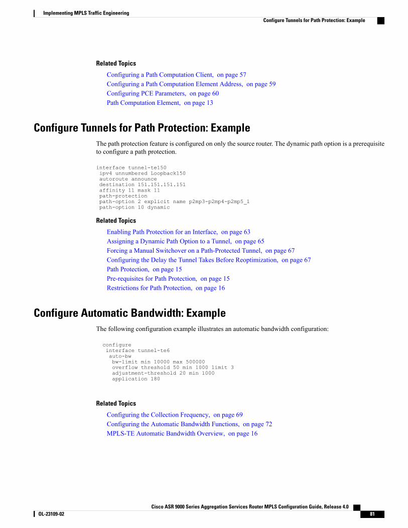
Related Topics
Configuring a Path Computation Client, on page 57Configuring a Path Computation Element Address, on page 59Configuring PCE Parameters, on page 60Path Computation Element, on page 13
Configure Tunnels for Path Protection: ExampleThe path protection feature is configured on only the source router. The dynamic path option is a prerequisiteto configure a path protection.
interface tunnel-te150ipv4 unnumbered Loopback150autoroute announcedestination 151.151.151.151affinity 11 mask 11path-protectionpath-option 2 explicit name p2mp3-p2mp4-p2mp5_1path-option 10 dynamic
Related Topics
Enabling Path Protection for an Interface, on page 63Assigning a Dynamic Path Option to a Tunnel, on page 65Forcing a Manual Switchover on a Path-Protected Tunnel, on page 67Configuring the Delay the Tunnel Takes Before Reoptimization, on page 67Path Protection, on page 15Pre-requisites for Path Protection, on page 15Restrictions for Path Protection, on page 16
Configure Automatic Bandwidth: ExampleThe following configuration example illustrates an automatic bandwidth configuration:
configureinterface tunnel-te6auto-bwbw-limit min 10000 max 500000overflow threshold 50 min 1000 limit 3adjustment-threshold 20 min 1000application 180
Related Topics
Configuring the Collection Frequency, on page 69Configuring the Automatic Bandwidth Functions, on page 72MPLS-TE Automatic Bandwidth Overview, on page 16
Cisco ASR 9000 Series Aggregation Services Router MPLS Configuration Guide, Release 4.0 OL-23109-02 81
Implementing MPLS Traffic EngineeringConfigure Tunnels for Path Protection: Example
Additional ReferencesFor additional information related to implementing MPLS-TE, refer to the following references:
Related Documents
Document TitleRelated Topic
MPLS Traffic Engineering Commands on Cisco ASR9000 Series Router module inCiscoASR9000SeriesAggregationServicesRouterMPLSCommand Reference
MPLS-TE commands
CiscoASR9000SeriesAggregationServicesRouterGettingStarted Guide
Getting started material
Standards
TitleStandards
—No new or modified standards are supported by thisfeature, and support for existing standards has notbeen modified by this feature.
MIBs
MIBs LinkMIBs
To locate and download MIBs using Cisco IOS XRsoftware, use the Cisco MIB Locator found at thefollowingURL and choose a platform under the CiscoAccess Products menu: http://cisco.com/public/sw-center/netmgmt/cmtk/mibs.shtml
—
RFCs
TitleRFCs
Protocol Extensions for Support of Diffserv-awareMPLS Traffic Engineering, F. Le Faucheur, Ed. June2005.
(Format: TXT=79265 bytes) (Status: PROPOSEDSTANDARD)
RFC 4124
Cisco ASR 9000 Series Aggregation Services Router MPLS Configuration Guide, Release 4.082 OL-23109-02
Implementing MPLS Traffic EngineeringAdditional References
TitleRFCs
Maximum Allocation Bandwidth Constraints Modelfor Diffserv-aware MPLS Traffic Engineering, F. LeFaucheur, W. Lai. June 2005.
(Format: TXT=22585 bytes) (Status:EXPERIMENTAL)
RFC 4125
Russian Dolls Bandwidth Constraints Model forDiffserv-aware MPLS Traffic Engineering, F. LeFaucheur, Ed. June 2005.
(Format: TXT=23694 bytes) (Status:EXPERIMENTAL)
RFC 4127
Technical Assistance
LinkDescription
http://www.cisco.com/techsupportThe Cisco Technical Support website containsthousands of pages of searchable technical content,including links to products, technologies, solutions,technical tips, and tools. Registered Cisco.com userscan log in from this page to access evenmore content.
Cisco ASR 9000 Series Aggregation Services Router MPLS Configuration Guide, Release 4.0 OL-23109-02 83
Implementing MPLS Traffic EngineeringAdditional References

Cisco ASR 9000 Series Aggregation Services Router MPLS Configuration Guide, Release 4.084 OL-23109-02
Implementing MPLS Traffic EngineeringAdditional References