implementing plug-and-play concepts in the development...
TRANSCRIPT

1
Implementing Plug-and-Play Concepts in the Development of an Attitude Determination and Control System to
Support Operationally Responsive Space
Paul Graven & Yegor Plam Microcosm, Inc. 4940 W. 147th St.
Hawthorne, CA 90250 310-219-2700
[email protected] & [email protected]
L. Jane Hansen HRP Systems, Inc.
4010 Palos Verdes Drive North, Suite 208
Rolling Hills Estates, CA 90274 310-541-2946
Seth Harvey PhD Candidate, University of
Wyoming 701 1/2 Kearney
Laramie, WY 82070
Abstract1—Operationally Responsive Space (ORS) has become the mantra for the next generation spacecraft that will support the warfighter. ORS missions require an extension of the current, traditional approach for fine-tuned, high cost, high accuracy attitude determination and control system (ADCS) software to create an ADCS system that can be developed much faster and less expensively. To achieve this faster, cheaper, and thus, better product, new technologies must be employed. These technologies show the promise of being disruptive, but enabling for ORS and very low-cost systems while potentially reducing cost and schedule for a broad range of systems. The introduction of Plug-and-Play (PnP) technologies to facilitate rapid integration may be effective in developing an ADCS that can be developed faster and at lower cost than current, traditional methods allow. However, this rapid integration and reduced non-recurring cost comes with an additional initial non-recurring engineering cost for implementing PnP. The goal is to demonstrate the potential of PnP ADCS by showing the improvements in performance, cost, and schedule, when the PnP ADCS software is demonstrated and tested. Additionally, the implementation of a Direct Model Reference Adaptive Controller (DMRAC) as the core for the ADCS software shows promise as an efficient method of providing stable, accurate control without requiring the extensive analysis, evaluation and gain tailoring that is typically required of more traditional controllers. Microcosm, with partner HRP Systems and graduate student Seth Harvey, have created prototype flight software that facilitates rapid integration through the implementation of PnP concepts while providing control performance suitable for many ORS missions, through the use of adaptive control algorithms. This paper will describe the software architecture, software implementation, adaptive control approach, and early evaluation results that are associated with the sponsored development of this PnP ADCS software.
1 IEEEAC paper #1586, Version 1.0
TABLE OF CONTENTS
1. INTRODUCTION.................................................. 1 PLUG-AND-PLAY FLIGHT SOFTWARE ARCHITECTURE .. 2 SENSORS ....................................................................... 2 ACTUATORS.................................................................. 2 CREATING GENERIC, REUSABLE FLIGHT SOFTWARE COMPONENTS ............................................................... 3 PLUG-AND-PLAY FLIGHT SOFTWARE PERFORMANCE ... 4
2. BODY ...................................................................... 5 DEMONSTRATION OF PNP FLIGHT SOFTWARE ARCHITECTURE............................................................. 5 DEMONSTRATION OF ADAPTIVE CONTROL FOR PNP... 10
3. CONCLUSION..................................................... 13 4. REFERENCES..................................................... 14 5. BIOGRAPHY ....................................................... 14
1. INTRODUCTION
The use of plug-and-play (PnP) technologies has been identified as an enabling technology for rapid integration and on-orbit subsystem discovery and configuration for a rapidly deployed space asset that is often associated with operationally responsive space (ORS). However, more than just PnP components are needed to assure that the spacecraft can meet the varying and often complex mission requirements imposed by the warfighter’s needs. The architecture of flight software must also be revised to meet the philosophy of the PnP paradigm. The Microcosm team has been instrumental in developing a PnP flight software architecture, with a focus on the attitude determination and control system (ADCS). The new architecture is data-centric and relies on the abstraction of the core algorithms from the specific sensor and actuator suites that are selected for each mission. The resulting implementation requires that partitioning of software and data be at the lowest levels, which has given rise to several new concepts, such as
2
atomic data elements and helper applications software modules (helper apps). Each of these is critical to reaping the benefits of PnP for ORS, particularly with respect to ADCS development.
Plug-and-Play Flight Software Architecture
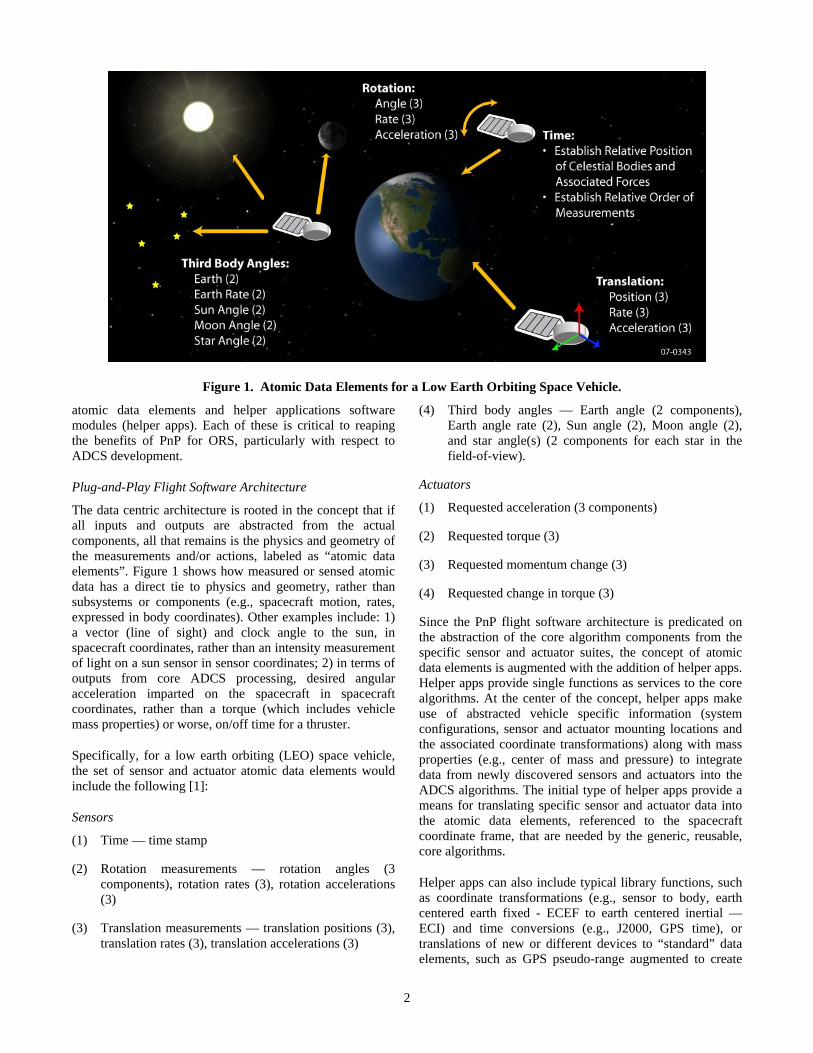
The data centric architecture is rooted in the concept that if all inputs and outputs are abstracted from the actual components, all that remains is the physics and geometry of the measurements and/or actions, labeled as “atomic data elements”. Figure 1 shows how measured or sensed atomic data has a direct tie to physics and geometry, rather than subsystems or components (e.g., spacecraft motion, rates, expressed in body coordinates). Other examples include: 1) a vector (line of sight) and clock angle to the sun, in spacecraft coordinates, rather than an intensity measurement of light on a sun sensor in sensor coordinates; 2) in terms of outputs from core ADCS processing, desired angular acceleration imparted on the spacecraft in spacecraft coordinates, rather than a torque (which includes vehicle mass properties) or worse, on/off time for a thruster.
Specifically, for a low earth orbiting (LEO) space vehicle, the set of sensor and actuator atomic data elements would include the following [1]:
Sensors
(1) Time — time stamp
(2) Rotation measurements — rotation angles (3 components), rotation rates (3), rotation accelerations (3)
(3) Translation measurements — translation positions (3), translation rates (3), translation accelerations (3)
(4) Third body angles — Earth angle (2 components), Earth angle rate (2), Sun angle (2), Moon angle (2), and star angle(s) (2 components for each star in the field-of-view).
Actuators
(1) Requested acceleration (3 components)
(2) Requested torque (3)
(3) Requested momentum change (3)
(4) Requested change in torque (3)
Since the PnP flight software architecture is predicated on the abstraction of the core algorithm components from the specific sensor and actuator suites, the concept of atomic data elements is augmented with the addition of helper apps. Helper apps provide single functions as services to the core algorithms. At the center of the concept, helper apps make use of abstracted vehicle specific information (system configurations, sensor and actuator mounting locations and the associated coordinate transformations) along with mass properties (e.g., center of mass and pressure) to integrate data from newly discovered sensors and actuators into the ADCS algorithms. The initial type of helper apps provide a means for translating specific sensor and actuator data into the atomic data elements, referenced to the spacecraft coordinate frame, that are needed by the generic, reusable, core algorithms.
Helper apps can also include typical library functions, such as coordinate transformations (e.g., sensor to body, earth centered earth fixed - ECEF to earth centered inertial — ECI) and time conversions (e.g., J2000, GPS time), or translations of new or different devices to “standard” data elements, such as GPS pseudo-range augmented to create
Figure 1. Atomic Data Elements for a Low Earth Orbiting Space Vehicle.
3
position/velocity. Helper apps might also include keep-out zones for payloads or instruments, orbit and attitude propagation, and the force models associated with that propagation. Even a Kalman Filter could be considered a helper app, as it makes use of atomic data elements that are available in the system and enhances them to create an optimal estimation of the vehicle state.
When helper apps are created to perform a single function, such as propagate the orbit from a requested initial time to an end time, the application can be encapsulated as a service that can be used by multiple “clients” to achieve varied objectives. For example, the same propagation routine, generically defined and fully tested can be used to determine if the sun is available to the solar arrays, to determine if a ground target is available for imaging, and to schedule a ground contact. Each of these disparate functions can be achieved using a single, generic service.
Creating Generic, Reusable Flight Software Components
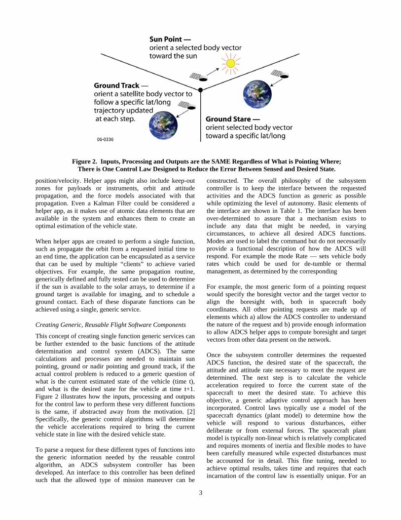
This concept of creating single function generic services can be further extended to the basic functions of the attitude determination and control system (ADCS). The same calculations and processes are needed to maintain sun pointing, ground or nadir pointing and ground track, if the actual control problem is reduced to a generic question of what is the current estimated state of the vehicle (time t), and what is the desired state for the vehicle at time t+1. Figure 2 illustrates how the inputs, processing and outputs for the control law to perform these very different functions is the same, if abstracted away from the motivation. [2] Specifically, the generic control algorithms will determine the vehicle accelerations required to bring the current vehicle state in line with the desired vehicle state.
To parse a request for these different types of functions into the generic information needed by the reusable control algorithm, an ADCS subsystem controller has been developed. An interface to this controller has been defined such that the allowed type of mission maneuver can be
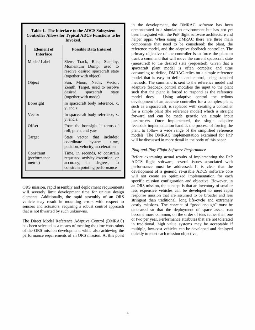
constructed. The overall philosophy of the subsystem controller is to keep the interface between the requested activities and the ADCS function as generic as possible while optimizing the level of autonomy. Basic elements of the interface are shown in Table 1. The interface has been over-determined to assure that a mechanism exists to include any data that might be needed, in varying circumstances, to achieve all desired ADCS functions. Modes are used to label the command but do not necessarily provide a functional description of how the ADCS will respond. For example the mode Rate — sets vehicle body rates which could be used for de-tumble or thermal management, as determined by the corresponding
For example, the most generic form of a pointing request would specify the boresight vector and the target vector to align the boresight with, both in spacecraft body coordinates. All other pointing requests are made up of elements which a) allow the ADCS controller to understand the nature of the request and b) provide enough information to allow ADCS helper apps to compute boresight and target vectors from other data present on the network.
Once the subsystem controller determines the requested ADCS function, the desired state of the spacecraft, the attitude and attitude rate necessary to meet the request are determined. The next step is to calculate the vehicle acceleration required to force the current state of the spacecraft to meet the desired state. To achieve this objective, a generic adaptive control approach has been incorporated. Control laws typically use a model of the spacecraft dynamics (plant model) to determine how the vehicle will respond to various disturbances, either deliberate or from external forces. The spacecraft plant model is typically non-linear which is relatively complicated and requires moments of inertia and flexible modes to have been carefully measured while expected disturbances must be accounted for in detail. This fine tuning, needed to achieve optimal results, takes time and requires that each incarnation of the control law is essentially unique. For an
Figure 2. Inputs, Processing and Outputs are the SAME Regardless of What is Pointing Where; There is One Control Law Designed to Reduce the Error Between Sensed and Desired State.
4
ORS mission, rapid assembly and deployment requirements will severely limit development time for unique design elements. Additionally, the rapid assembly of an ORS vehicle may result in mounting errors with respect to sensors and actuators, requiring a robust control approach that is not thwarted by such unknowns.
The Direct Model Reference Adaptive Control (DMRAC) has been selected as a means of meeting the time constraints of the ORS mission development, while also achieving the performance requirements of an ORS mission. At this point
in the development, the DMRAC software has been demonstrated in a simulation environment but has not yet been integrated with the PnP flight software architecture and helper apps. When using DMRAC there are three main components that need to be considered: the plant, the reference model, and the adaptive feedback controller. The primary objective of the controller is to force the plant to track a command that will move the current spacecraft state (measured) to the desired state (requested). Given that a spacecraft plant model is often complex and time consuming to define, DMRAC relies on a simple reference model that is easy to define and control, using standard methods. The command is sent to the reference model and adaptive feedback control modifies the input to the plant such that the plant is forced to respond as the reference model does. Using adaptive control the tedious development of an accurate controller for a complex plant, such as a spacecraft, is replaced with creating a controller for a simple plant (the reference model) which is straight forward and can be made generic via simple input parameters. Once implemented, the single adaptive feedback implementation handles the process of forcing the plant to follow a wide range of the simplified reference models. The DMRAC implementation examined for PnP will be discussed in more detail in the body of this paper.
Plug-and-Play Flight Software Performance
Before examining actual results of implementing the PnP ADCS flight software, several issues associated with performance must be addressed. It is clear that the development of a generic, re-usable ADCS software core will not create an optimized implementation for each specific mission configuration and objective. However, in an ORS mission, the concept is that an inventory of smaller less expensive vehicles can be developed to meet rapid response mission that are assumed to be broader and less stringent than traditional, long life-cycle and extremely costly missions. The concept of “good enough” must be embraced so that the deployment of space assets can become more common, on the order of tens rather than one or two per year. Performance attributes that are not tolerated in traditional, high value systems may be acceptable if multiple, low-cost vehicles can be developed and deployed quickly to meet each mission objective.
Table 1. The Interface to the ADCS Subsystem Controller Allows for Typical ADCS Functions to be
Invoked.
Element of Interface
Possible Data Entered
Mode / Label Slew, Track, Rate, Standby, Momentum Dump, used to resolve desired spacecraft state (together with object)
Object Sun, Moon, Nadir, Vector, Zenith, Target, used to resolve desired spacecraft state (together with mode)
Boresight In spacecraft body reference, x, y, and z
Vector In spacecraft body reference, x, y, and z
Offset From the boresight in terms of roll, pitch, and yaw
Target State vector that includes: coordinate system, time, position, velocity, acceleration
Constraint (performance metric)
Time, in seconds, to constrain requested activity execution, or accuracy, in degrees, to constrain pointing performance
5
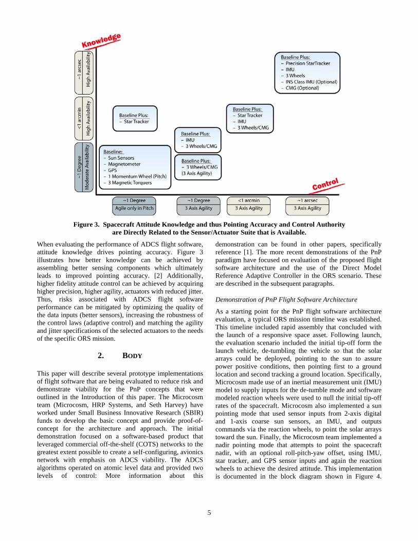
When evaluating the performance of ADCS flight software, attitude knowledge drives pointing accuracy. Figure 3 illustrates how better knowledge can be achieved by assembling better sensing components which ultimately leads to improved pointing accuracy. [2] Additionally, higher fidelity attitude control can be achieved by acquiring higher precision, higher agility, actuators with reduced jitter. Thus, risks associated with ADCS flight software performance can be mitigated by optimizing the quality of the data inputs (better sensors), increasing the robustness of the control laws (adaptive control) and matching the agility and jitter specifications of the selected actuators to the needs of the specific ORS mission.
2. BODY
This paper will describe several prototype implementations of flight software that are being evaluated to reduce risk and demonstrate viability for the PnP concepts that were outlined in the Introduction of this paper. The Microcosm team (Microcosm, HRP Systems, and Seth Harvey) have worked under Small Business Innovative Research (SBIR) funds to develop the basic concept and provide proof-of-concept for the architecture and approach. The initial demonstration focused on a software-based product that leveraged commercial off-the-shelf (COTS) networks to the greatest extent possible to create a self-configuring, avionics network with emphasis on ADCS viability. The ADCS algorithms operated on atomic level data and provided two levels of control: More information about this
demonstration can be found in other papers, specifically reference [1]. The more recent demonstrations of the PnP paradigm have focused on evaluation of the proposed flight software architecture and the use of the Direct Model Reference Adaptive Controller in the ORS scenario. These are described in the subsequent paragraphs.
Demonstration of PnP Flight Software Architecture
As a starting point for the PnP flight software architecture evaluation, a typical ORS mission timeline was established. This timeline included rapid assembly that concluded with the launch of a responsive space asset. Following launch, the evaluation scenario included the initial tip-off form the launch vehicle, de-tumbling the vehicle so that the solar arrays could be deployed, pointing to the sun to assure power positive conditions, then pointing first to a ground location and second tracking a ground location. Specifically, Microcosm made use of an inertial measurement unit (IMU) model to supply inputs for the de-tumble mode and software modeled reaction wheels were used to null the initial tip-off rates of the spacecraft. Microcosm also implemented a sun pointing mode that used sensor inputs from 2-axis digital and 1-axis coarse sun sensors, an IMU, and outputs commands via the reaction wheels, to point the solar arrays toward the sun. Finally, the Microcosm team implemented a nadir pointing mode that attempts to point the spacecraft nadir, with an optional roll-pitch-yaw offset, using IMU, star tracker, and GPS sensor inputs and again the reaction wheels to achieve the desired attitude. This implementation is documented in the block diagram shown in Figure 4.
Figure 3. Spacecraft Attitude Knowledge and thus Pointing Accuracy and Control Authority are Directly Related to the Sensor/Actuator Suite that is Available.

6
The ADCS software used for this architecture evaluation is representative of the type of software that would be used to operate a typical spacecraft of this class. The software has been integrated with the AFRL middleware infrastructure that supports data discovery, publishing, and subscribe. The purpose of this evaluation is to determine how well simple ADCS algorithms will perform in an architecture where determinism for data delivery intervals is not guaranteed and latency may vary with each measurement received. Thus, several assumptions were made to simplify the control laws. Each of these may be increased in fidelity with
time and the addition of DMRAC algorithms, proven separately, will be one of the first enhancements made. The current control algorithm is based on a simple proportional-derivative (PD) controller that matches only position and not rates, for this evaluation. The spacecraft, once functional on-orbit, is nadir pointing and is assumed to point to a geo-location. Some additional requirements were captured in the block diagram (Figure 4) for the longer term implementation that makes use of multiple helper applications with message formats from each of the sensor/actuator components.
Figure 4. ADCS Flight Software Elements to Implement a Typical ORS Mission Scenario
7
Another assumption for this implementation included the concept that the spacecraft mass properties were static, specifically, the effects associated with the deployment of solar arrays, propellant sloshing in propellant tanks, and the articulation of antennas and/ or sensors will not impact the mass and thus will not impact the control system. Next, the initial tip-off of the spacecraft from the launch vehicle was assumed to be less than 30 degrees per minute (multiple axes are acceptable) so that the system can stabilize quickly for utilization in the rapid response orbit. It was assumed that the vehicle has 4 wheels, and is a zero momentum system so that the wheels can be quickly spun up and null out the torque(s). In terms of the solar arrays, it was assumed that they were deployed and locked — there was not any unique software to optimize the relationship between the arrays and the sun.
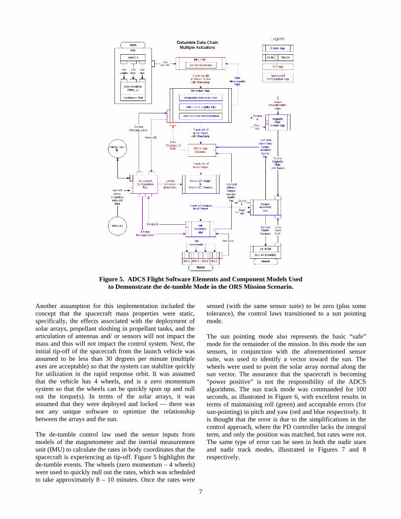
The de-tumble control law used the sensor inputs from models of the magnetometer and the inertial measurement unit (IMU) to calculate the rates in body coordinates that the spacecraft is experiencing as tip-off. Figure 5 highlights the de-tumble events. The wheels (zero momentum – 4 wheels) were used to quickly null out the rates, which was scheduled to take approximately 8 – 10 minutes. Once the rates were
sensed (with the same sensor suite) to be zero (plus some tolerance), the control laws transitioned to a sun pointing mode.
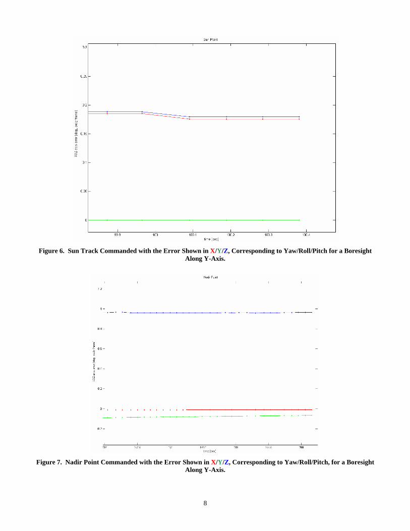
The sun pointing mode also represents the basic “safe” mode for the remainder of the mission. In this mode the sun sensors, in conjunction with the aforementioned sensor suite, was used to identify a vector toward the sun. The wheels were used to point the solar array normal along the sun vector. The assurance that the spacecraft is becoming “power positive” is not the responsibility of the ADCS algorithms. The sun track mode was commanded for 100 seconds, as illustrated in Figure 6, with excellent results in terms of maintaining roll (green) and acceptable errors (for sun-pointing) in pitch and yaw (red and blue respectively. It is thought that the error is due to the simplifications in the control approach, where the PD controller lacks the integral term, and only the position was matched, but rates were not. The same type of error can be seen in both the nadir stare and nadir track modes, illustrated in Figures 7 and 8 respectively.
Figure 5. ADCS Flight Software Elements and Component Models Used to Demonstrate the de-tumble Mode in the ORS Mission Scenario.
8
Figure 6. Sun Track Commanded with the Error Shown in X/Y/Z, Corresponding to Yaw/Roll/Pitch for a Boresight
Along Y-Axis.
Figure 7. Nadir Point Commanded with the Error Shown in X/Y/Z, Corresponding to Yaw/Roll/Pitch, for a Boresight
Along Y-Axis.
9
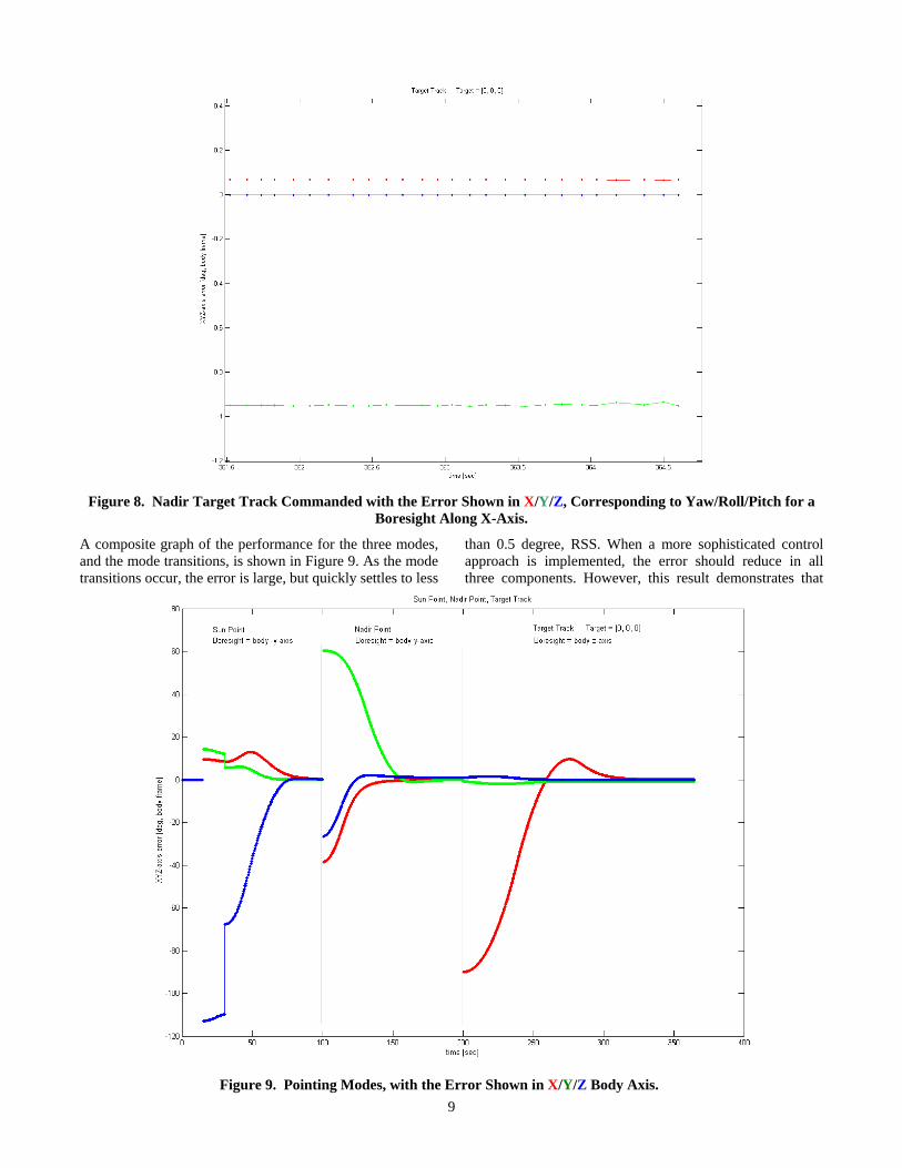
Figure 8. Nadir Target Track Commanded with the Error Shown in X/Y/Z, Corresponding to Yaw/Roll/Pitch for a
Boresight Along X-Axis.
A composite graph of the performance for the three modes, and the mode transitions, is shown in Figure 9. As the mode transitions occur, the error is large, but quickly settles to less
than 0.5 degree, RSS. When a more sophisticated control approach is implemented, the error should reduce in all three components. However, this result demonstrates that
Figure 9. Pointing Modes, with the Error Shown in X/Y/Z Body Axis.

10
the PnP infrastructure and short-comings from a real-time system perspective can be accommodated for a spacecraft ADCS implementation. Further, more detailed study is required, but the basic proof-of-concept has been successful.
Demonstration of Adaptive Control for PnP
The general goal of the DMRAC work presented here was to determine how well the algorithms would perform given the characteristics of a PnP satellite (PnPSat). The evaluation had an emphasis on simulation, where the actuator limitations and saturation, as well as the processor speed and register size were evaluated parametrically. Attitude maneuvers typical of the maneuvers that would be expected of the PnPSat were simulated and the results have been plotted. Table 2 details the simulation parameters used for the controller. These simulations assume that there are three reaction wheels present, along with the necessary sensor package to deliver the controller an “idealized” attitude quaternion and angular velocity of the spacecraft. The input of the simulated DMRAC attitude controller is the satellite attitude quaternion and the angular velocity of the vehicle, along with the desired attitude quaternion and angular velocity couple. The output of the controller is a torque command. The simulation satellite was then commanded to execute a variety of consecutive maneuvers, representative of spacecraft activities: a 10 degree slew which might simulate pointing an antenna toward a specified vector; pointing toward the sun, which simulates sunbathing for power revitalization; and trajectory tracking, which simulates ground tracking. The precise simulation maneuvers and their order are shown in Table 3.
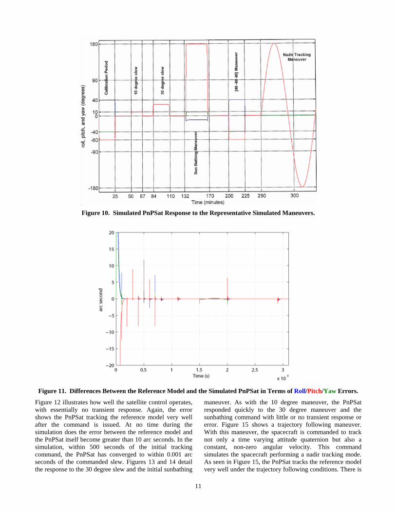
Based on the scenario outlined in Table 3, simulations were run and the combined results can be seen in Figure 10. From a broad perspective of the entire simulation, the controller looks to be a success. The simulated PnPSat tracks the commands nicely and the adaptive controller requires less than 5 minutes to reduce the error between the PnPSat and the reference model to less than one arcsecond. Figure 11 provides a closer look at the results, with a specific emphasis on the roll-pitch-yaw error between the satellite and the reference model of the DMRAC. The spikes seen in Figure 11 are at the beginning of each “new” command where there is an initial (although relatively small) error between PnPSat and the reference model. This error is quickly reduced as the adaptive controller takes over and compensates for the nonlinearity between the current and last measurement. The graph identifies that calibration takes
about 30 minutes. Once the calibration period is complete, the error between the satellite and the reference model stays small, less than one arcsecond.
Table 2. Simulation Parametric Elements for Evaluation of the DMRAC.
Parameters Parameter Values PnPSat Inertia Matrix 27 12 6
12 32 4 6 4 20
Altitude 650 km Actuator Inertia 0.000982029 kg m2 Momentum Capacity of each RW
1.0 kg*m/s
Torque Capacity of each RW
0.5 Nm
Simulated Processor 20Hz 8 – bit Generic Embedded Processor
Solver Method Matlab Ode3 (Runge-Kutta)
Table 3. Simulation Maneuvers Representing PnPSat Command Modes.
Maneuver Description
Command Roll/Pitch/Yaw Values (deg)
Calibration Period Slew to [40 -40 -60] and slew back to nadir
10 deg Slew Slew to [10 10 10] and slew back to nadir
30 degree slew Slew to [30 30 30] and slew back to nadir
Large slew Slew to [40 -40 -60] and slew back to nadir
Sunbath Maneuver Slew to [-10 -10 179] and slew back to nadir
Track Nadir Track nadir for one simulation orbit (5000 sec)
Sunbath maneuver Slew to [-30 10 -180] and slew back to nadir
11
Figure 10. Simulated PnPSat Response to the Representative Simulated Maneuvers.
Figure 11. Differences Between the Reference Model and the Simulated PnPSat in Terms of Roll/Pitch/Yaw Errors.
Figure 12 illustrates how well the satellite control operates, with essentially no transient response. Again, the error shows the PnPSat tracking the reference model very well after the command is issued. At no time during the simulation does the error between the reference model and the PnPSat itself become greater than 10 arc seconds. In the simulation, within 500 seconds of the initial tracking command, the PnPSat has converged to within 0.001 arc seconds of the commanded slew. Figures 13 and 14 detail the response to the 30 degree slew and the initial sunbathing
maneuver. As with the 10 degree maneuver, the PnPSat responded quickly to the 30 degree maneuver and the sunbathing command with little or no transient response or error. Figure 15 shows a trajectory following maneuver. With this maneuver, the spacecraft is commanded to track not only a time varying attitude quaternion but also a constant, non-zero angular velocity. This command simulates the spacecraft performing a nadir tracking mode. As seen in Figure 15, the PnPSat tracks the reference model very well under the trajectory following conditions. There is

12
some varying error, but the error remains less than 0.2 arc seconds between the PnPSat and reference model. These simulations also accounted for actuator limitations as specified by the selected PnPSat reaction wheels. Figure 16
shows the wheel speed and commanded torque during this process of maneuvering.
Sunbathing Maneuver of Simulated PnPSat Error Associated with the Sunbathing
Figure 14. Simulation Results for a Sunbathing Maneuver.
. 10 degree Slew Maneuver of Simulated PnPSat Error Associated with the Commanded Slew
Figure 12. Simulation Results for a 10 Degree Slew Maneuver.
30 degree Slew Maneuver of Simulated PnPSat Error Associated with the Commanded Slew
Figure 13. Simulation Results for a 30 Degree Slew Maneuver.

13
Trajectory Tracking of Simulated PnPSat Error Associated with the Trajectory Tracking
Figure 15. Simulation Results for a Trajectory Tracking Command.
Reaction Wheel Speed Commanded Reaction Wheel Torque
Figure 16. Wheel Speed and Commanded Torque of the PnPSat Representative Reaction Wheels.
In general, the DMRAC approach demonstrates significant innovation and accommodates rapid integration, where precision alignment and instrument calibration may not occur due to time limitations, with minimal risk. The algorithms are based on simple dynamic equations that have proven stability. The implementation is portable between different spacecraft, given that they are the same basic class (imaging versus communications) and size (400 kg. versus 1,200 kg.) The DMRAC algorithms will be included in the flight software in the loop (FSWIL) simulation environment, in place of the PD controller that has been tested, and further evaluation will continue.
3. CONCLUSION
The PnP concept, as applied to subsystem components can greatly reduce the integration time of a space asset by allowing the system to use self-discovery once the vehicle is assembled. Likewise, the PnP paradigm can be leveraged to create a flight software architecture that will facilitate reuse and thus reduce development time and non-recurring costs. When ADCS software is developed from the first principles of physics, using atomic data elements, it can be created in such a way that it will be extensible and reusable under varying conditions. Additionally, the use of helper apps to create low level functions that can be “chained” together to
provide solutions for more complex, and often different objectives, enhances the reuse possibilities for those software elements. The creation of other helper apps that are associated with specific subsystem components, translating their intrinsic output to the atomic data used by the system, further allows for the abstraction of the core algorithms from the specific sensors and actuators. The final step of using an innovative approach to adaptive control has initially proven successful and further evaluation is in work. Taken together, these elements of the new flight software architecture will, in fact, facilitate the PnP paradigm in a software implementation.
The question that remains is: if the ADCS flight software is generic and reusable, will the software performance be “good enough” to meet the ORS objectives? The ORS objectives are still evolving but will soon be established. Once the objectives have been established, the question of PnP flight software performance will be answered through flight-software-in-the-loop (FSWIL) simulation based on realistic scenarios and requirements. Moreover, this question will continue to be explored through hardware-in-the-loop (HWIL) integration at AFRL in the Responsive Space Testbed (RST). Finally, with continued support, AFRL will lead the way in demonstrating that PnP is “good enough” through on-orbit experimentation as the PnPSat is

14
launched and made operational for experimentation and research.
4. REFERENCES
[1] Achieving Responsive Space: The Viability of Plug-and-Play in Spacecraft Development (AAS 06-034) written by Paul Graven and Dr. Richard Van Allen, L. Jane Hansen and Jon M. Pollack and presented at the 29th ANNUAL AAS GUIDANCE AND CONTROL CONFERENCE February 4-8, 2006
[2] A Guidance, Navigation and Control (GN&C) Implementation of Plug-and-Play for Responsive Spacecraft (AIAA20079391), written and presented by L. Jane Hansen and Paul Graven at AIAA Infotech@Aerospace 2007 Conference and Exhibit, 7 – 10 May 2007, Rohnert Park, California
5. BIOGRAPHY
Paul H. Graven is the Director of Technology Development at Microcosm, in Hawthorne CA. Prior to joining Microcosm he spent 5 years as a management consultant developing growth strategies for early stage technology companies.
He received his MS in Aeronautics & Astronautics from Stanford University, and his BS in Engineering & Applied Science, and Economics from the California Institute of Technology. He also received a Master’s in Public Policy from Harvard University’s John F. Kennedy School of Government –focusing on science and technology policy and national security policy.
He has authored or coauthored many spacecraft guidance, navigation and control (GN&C) related papers, and is currently the Principal Investigator for one NASA and two Air Force GN&C focused programs.
He is a member of AAAS, AAS, AGU, AIAA, IEEE, ION, SCEA, and SPIE.
Yegor Plam received the B.S. and M.S. degrees in Aerospace Engineering from the University of Colorado, Boulder, in 2002 and 2004, respectively.
He is currently a Systems Engineer in the Space Systems Division of
Microcosm, Inc. His expertise is in orbital mechanics, control systems and computer simulations. Mr. Plam has acquired over ten years of software engineering experience from GTE Data Services, Utility Partners, MCI, and the Orbital Control Systems Lab and the Space Grant Consortium at the University of Colorado. Mr. Plam has mission operations experience from the Laboratory for Atmospheric and Space Physics in Boulder, Colorado.
Ms. L. Jane Hansen has nearly 30 years of experience in the aerospace industry —providing engineering and management support for avionics systems on board aircraft, spacecraft, rockets, launch vehicles, and ballistic missiles. Ms Hansen has a BS in Applied Mathematics from California Polytechnic State University in San Luis
Obispo and an MBA from Pepperdine University. Currently, Ms. Hansen is President of HRP Systems, a woman-owned, small aerospace company established in 1991 and located in Southern California. Over the years, Ms. Hansen has supported large aerospace prime contractors such as Northrop Grumman Integrated Systems, Northrop Grumman Space Technologies (formerly TRW), and NASA Jet Propulsion Laboratory (JPL), mid-sized organizations such as Rocketdyne, Ruggedized Digital, and DEC, as well as supporting smaller aerospace companies such as Microcosm, RSI, and Eidetics. She has acted as primary systems engineer, with responsibility for requirements, design, test, and interface control documentation, in support of various avionics, software, and simulation development efforts. Additionally, Ms. Hansen led the avionics development effort for a commercial unmanned aerial vehicle (UAV) and created a business plan to acquire commercial funding for such a venture. Ms. Hansen is Associate Fellow in the AIAA.
Seth Harvey is a student and PhD candidate of Mark Balas at the University of Wyoming. His thesis research looks at adaptive attitude of spacecraft. Before attending The University of Wyoming, Mr. Harvey received bachelor's degrees in computer science and electrical engineering from Montana School of Mines. Before that Mr. Harvey was home schooled.
He enjoys outdoor activities and dislikes eggplant.