implementing precision approaches supported by satellite
TRANSCRIPT

Implementing Precision Approaches Supported bySatellite-Based Augmentation Systems in the Austrian Alps
Carlos Gonzaga-López∗ and Florian Michael Buchmann∗
Austro Control, GmbH, 1220 Vienna, Austria
andThomas Dautermann† and Thomas Ludwig†
DLR, German Aerospace Center, 38108 Brunswick, Germany
https://doi.org/10.2514/1.D0155
Aerodromes located in mountainous areas are seldom served by approaches with three-dimensional guidance
based on instrument landing systems due to the lack of flexibility to define glide paths free of obstacles. But, three-
dimensional approaches are always preferred due to their effectiveness against controlled flight into terrain.
Free access to three-dimensional angular approaches is possible today without special authorization and ground
infrastructure. Some airports in mountainous areas of the United States, Canada, and Europe already benefit from
them due to the latest advances in satellite-based augmentation techniques. The majority of these procedures have
not been developed as category-one precision approaches, even though the latest operational service level foresees it.
Reported here are the signal assessment and procedure design carried out to enable the first category-one precision
approach supported by satellite-based augmentation system at an Austrian airport surrounded by one of the most
challenging terrainsworldwide. Thedesign and implementation of sucha procedure inmountainous terrain is feasible
after a thorough signal quality assessment. It can be placed where a classical instrument landing-system-based
approach procedure does not work and provides precision guidance for aircraft in instrument meteorological
conditions. This in turn enables a higher runway throughput and reduces cost for the users. When the controlling
obstacle is located outside of the precision segment, special attention should be put on the availability requirements.
I. Introduction
A ERODROMES in demanding mountainous environments areusually served by two-dimensional (2-D) approach procedures
without vertical guidance to achieve lower minima by establishingstepdown descent profiles. However, the absence of vertical guidanceincreases significantly the likelihood of controlled flight into terrain(CFIT) due to loss of situational awareness and high cockpit work-load during approach and landing in instrument meteorological con-ditions when any outside references can only be visually acquiredshortly before landing. CFIT is a type of aircraft accident in which anairworthy aircraft with full pilot control is unintentionally flown intothe ground, into a mountain, or into an obstacle. Usually, the flightcrew is oblivious of the imminent danger. The International CivilAviation Organization’s (ICAO’s) Assembly Resolution A37-11urges member states to implement instrument approach procedures(IAPs) with vertical guidance, wherever possible, as an effectivemitigation against CFIT. An IAP is a repeatable and charted methodto conduct an approach for landing at an airport. It safely guides theaircraft from arrival altitude to a point from which the landing can beperformed.The recent developments in the field ofGlobal Navigation Satellite
Systems (GNSSs) and its augmentations have opened up a newspectrum of possibilities in aviation. Concretely, the satellite-basedaugmentation system (SBAS) [1] now enables three-dimensional(3-D) instrument landing system (ILS)-like approaches, also knownas localizer performance with vertical guidance (LPV). Both provideangular deviations from the centerline and glide path to the pilot, butthe ILS does so by means of ground-based radio transmitters,whereas LPVis computed fromGNSSposition data. LPVapproaches
have proven to be a cost-efficient solution to overcome airspacelimitations and reduce noise impact [2]. Legacy design criteria andavailable levels of service, known as the approach procedure withvertical guidance (APV), have supported LPV operations down to250 ft above runway threshold formany years.With the improvementof the signal performance, new operational service levels and designcriteria have been defined to support LPVoperations down to 200 ft,qualifying these types of procedures as precision approaches for thefirst time. This is called LPV200 or LPV category-one (CAT-I). As ofJanuary of 2019 there are around 4000 LPVoperational approachesin the United States of America (USA), 400 in Canada, and around500 in Europe. India and Japan are expected to publish their firstLPV approaches in the near future. However, the implementationof precision approaches in complex mountainous environments isstill marginal. High aerodrome operatingminima in terms of decisionheight (DH) and the blockage of satellite signals by terrain (alsoknown as terrain masking) are the most common limiting factors[3,4]. DH is the minimum height above ground at which the pilotmust have established visual reference to the landing runway. If this isnot the case, he or she must follow a predetermined missed approachprocedure. The LPV approaches to the Astronaut Kent RomingerAirport (ICAO code KRCV) from the east and to Mc Elroy Airfield(ICAO code K20V) from the north in the state of Colorado constitutegood examples of approaches in challenging terrain with landingminima well above 250 ft [5]. In the USA, LPVs are designed ascategory-one precision approaches only if the corresponding landingminima can be below 250 ft as, for example, the approach to JacksonHole (ICAO code KJAC) from the north in the state of Wyoming [5].This is not always the case in Europe, where a mixture of legacyAPVs and new CAT-I LPVs can be found serving runways whereprevailing terrain precludes CAT-I landing minima below 250 ft. Forexample, the LPVapproaches to Sogndal (ICAO code ENSG) (Nor-way) from the east [6] and to Annecy (ICAO code LFLP) (France)from the south [7] were designed as CAT-I precision approaches,even though the resulting DH lies well above 250 ft, thus discardingany possibility of CAT-I operations based on the SBAS. On the otherhand, LPVapproaches in similar environments, such as those to theregional airport of Bern-Belp (ICAO code LSZB) (Switzerland) [8],were designed as APVs and not as precision approaches.
Received 18November 2018; revision received17April 2020; accepted forpublication 17 May 2020; published online Open Access 11 June 2020.Copyright © 2020 by the authors. Published by the American Institute ofAeronautics and Astronautics, Inc., with permission. All requests for copyingand permission to reprint should be submitted to CCC at www.copyright.com;employ the eISSN 2380-9450 to initiate your request. See also AIAA Rightsand Permissions www.aiaa.org/randp.
*Air Traffic Management Department, IFP Office, Wagramer Straße 19.†Ph.D., Institute of Flight Guidance, Department of Pilot Assistance,
Lilienthalplatz 7, Braunschweig; [email protected].
Article in Advance / 1
JOURNAL OF AIR TRANSPORTATION
Dow
nloa
ded
by D
LR
DE
UT
SCH
ES
ZE
NT
RU
M F
UE
R L
UFT
UN
D R
AU
MFA
HR
T o
n Ju
ne 1
2, 2
020
| http
://ar
c.ai
aa.o
rg |
DO
I: 1
0.25
14/1
.D01
55

The fact that LPV approaches are independent of ground infra-structure is of particular relevance for small general and businessaviation aerodromeswhere the costs of instrument landing aids do notfulfill the business case or where the topography impedes the optimalplacement of such. The Austrian airport of Innsbruck, under ICAOcode LOWI, represents a good example of this limitation. This airportlies in a valley flanked by high and steep mountains (see Fig. 1),which can pose a great challenge to pilots and air traffic controllers incombination with adverseweather. Accessibility to Innsbruck airportis key to the economic development of the region, especially duringthewinter season. For that reason, Innsbruck is a breeding ground forsome of the most innovative flight procedures worldwide.The most advanced 3-D approaches currently implemented in
Innsbruck are based on the navigation specification of requirednavigation performance (RNP)/authorization required (AR), referredto as RNP-AR, and are flown by most airliners with special authori-zation. A navigation specification can be seen as a set of aircraft andcrew requirements that need to be met for a specific phase of flight.The navigation specification also defines the navigational tolerancesthat are to be used to create the containment areas and assess obstruc-tions according to the specific design criteria. A detailed list of theavailable navigation specification to date can be found in Ref. [9].RNP-AR capabilities are traditionally out of scope for the generalaviation community due to the increased costs associated with moredemanding training and airworthiness certification requirements. No3-D approach procedure based on standard RNP navigation specifi-cation (without special authorization required), conventional ILS, or acombination of both could be implemented until now in Innsbruckdue to topographic constraints. As a consequence, most generalaviation inbound flights to runway 26 (standard approach configura-tion) still rely on a 2-D offset localizer/distancemeasuring equipment(LOC/DME) approach. In a LOC/DME approach procedure, thelateral guidance is provided by a very high-frequency-based localizerdirectional aid [10] and distance information is provided by ultrahighfrequency distance measuring equipment (DME). In this nonpreci-sion approach, the vertical path is managed by the pilot throughaltitude restrictions at stepdown fixes. Despite the existence of a steepadvisory glide slope at a nonstandard vertical path angle (VPA) inInnsbruck, the publication of standard 3-D approaches can contributeto lowering the risk of CFIT by enabling better aircraft energymanagement during the approachwith less pilotworkload. The safetybenefits are even more evident if the approach guidance systemprovides the user with angular sensitivity and geometrical verticalguidance. This type of vertical guidance is not subject to barometricaltimetry errors such as temperature variations and Bernoulli effects,which are very common in mountainous areas. Moreover, GNSS-guided approaches eliminate critical areas in the final approach due toreflection of the glide slope and/or localizer beams.In this paper,we describe the implementation process carried out to
make possible the first 3-D approach with angular sensibility at thealpine airport of Innsbruck, based on SBAS and with no specialauthorization requirement.
II. Signal Analysis
We considered European Geostationary Navigation Overlay Ser-vice (EGNOS) as themost appropriate technological means to date inorder to provide approach navigation service to the general andbusiness aviation community in Innsbruck. EGNOS is a SBAS,i.e., an enhanced differential Global Positioning System (GPS) thatprovides signal corrections plus signal quality parameters to users.The user can then augment its measurements to compute a moreprecise position. SBAS provides means for high-quality approachesthat do not depend on ground-based navigational aids and do notrequire any special approval. Since 2015, EGNOSoffers the LPV200service level on a free-of-charge basis in an extensive area acrossEurope [11]. This service level supports 3-D approach operations oftypeBdown to 200 ft above runway threshold elevation [12],whereasthe legacy LPV service level does down to 250 ft. The LPV200service also enables the application of ICAO CAT-I design criteriawith less restrictive obstacle assessment surfaces (OASs) [13]. Fur-ther details on Global Navigation Satellite System signal-in-spacerequirements for SBAS CAT-I design criteria can be found inRef. [14]. Before undertaking the design phase of the flight pro-cedure, it is of paramount importance to ensure the availability of therequired signal in the area of interest. Given the complex topographyof the alpine area of Innsbruck and its possible effects on the aug-mented navigational signal, we decided to use a combined approachbased on both simulations and on-site measurements.
A. Terrain Masking
To predict EGNOS performance in Innsbruck, we used a digitalterrain model of themountainous topography surrounding the airportwith a spatial resolution of 50m.We chose seven characteristic pointson the existing runway (RWY) 26 localizer (LOC) approach atwhich we calculated satellite elevation masks due to the terrain witha resolution of 5 deg in azimuth (see Fig. 1). Obstructions due toterrain becomemore prominent the lower on the approach the aircraftis located. Figure 2 shows that, at the lowest point on the existingLOC/DME approach (at 3.5 nmiles of DME distance), both EGNOSsatellites are still visible to the user. The position of the EGNOSbroadcast satellite PseudoRandomNoise (PRN)120 ismarked in red,whereas the PRN136 is marked in black. The terrain elevation maskcan reach up to 16 deg at a direction of 345 deg from the airport.However, in the north, there are few satellites visible due to theGlobalPositioning System orbital geometry.
B. Protection Level Prediction
To assess EGNOS performance for the LPV200 service level inInnsbruck, we need to calculate a prediction of integrity data in theform of protection levels as calculated by a receiver in real time.Protection levels correspond to the ad hoc estimate of the positionuncertainty with a probability of one minus the integrity risk. In otherwords, if the integrity risk is 2 × 10⁻⁷, then the user is 99.99998%certain that the estimated position is within the cylinder defined byradius horizontal protection level (HPL) andheight vertical protection
Fig. 1 Terrain elevation around Innsbruck airport (ICAO identifier LOWI) and characteristic points. Light tones represent the highest elevations.
2 Article in Advance / GONZAGA-LÓPEZ ETAL.
Dow
nloa
ded
by D
LR
DE
UT
SCH
ES
ZE
NT
RU
M F
UE
R L
UFT
UN
D R
AU
MFA
HR
T o
n Ju
ne 1
2, 2
020
| http
://ar
c.ai
aa.o
rg |
DO
I: 1
0.25
14/1
.D01
55

level (VPL). Details on the SBAS message and the calculation ofaugmented user position and integrity data can be found, for example,in Ref. [15]. Themainmodel parameters needed for the calculation ofthe protection levels are the satellite geometry, the user differentialrange error index (UDREI), and the grid ionosphere vertical errorindex (GIVEI). UDREIs are 4 bit integer data that are broadcast bythe SBAS satellites and used to indicate the accuracy of combinedfast and long-term error corrections. The SBAS system assigns aninteger from 0 through 15 to each GNSS constellation satellite that ismonitored. By means of a lookup table in Ref. [15], a variance isassigned and used in the computation of position and protectionlevels. Similarly, the SBAS broadcasts information about the currentstate of the ionosphere. These data consist of the vertical ionospheresignal delay and the GIVEI. Again, the GIVEI are 4 bit integervalues from 0 to 15 describing the variance of the ionosphere delayestimate at each grid point. To compute a meaningful prediction ofthe protection levels, and thusEGNOSperformance,we need tomakequalified assumptions on those quantities. They are also the maininput parameters of Stanford University’s MATLAB AlgorithmAvailability Simulation Tool (MAAST) [16]. MAAST providesproven program code for simulation of the GPS constellation basedon ephemeris data and user location as well as performance tools toanalyze navigation integrity, availability, continuity, and accuracy.We calculated predicted approach protection levels using a currentalmanac (basic set of parameters describing a satellite orbit [17]) fromGPS week 841 (�1024) and the Stanford MAAST Toolkit. Sincethe standard MAAST does not foresee to use different UDREIs andGIVEIs per satellite, we modified the open software to include thisfunctionality. Details onMAAST can be found inRef. [16]. To obtaina realistic value for the GIVEI and UDREI, we ran a statisticalanalysis over all GIVEI data for the EGNOS in band 4 and band 5located over central Europe. Bands 4 and 5 are sufficient because theycovermost of the central European landmass. An overview of the gridpoint locations and bands can be found in RTCA Standard DO-229D[15]. The EGNOS message data were obtained from the EGNOSmessage ftp server.§ We used functions of RTKlib to decode the rawmessages and extract the relevant GIVEI data. Details on the RTKlib
functionality can be found inRef. [18].We also performed a statisticalanalysis on the UDREI per PRN. From the statistical data, wecalculated the mean of the UDREI for 2015 and rounded up tothe nearest integer value. Using MAAST and the average GIVEIand UDREI from 2015, as well as the satellite elevation masksbased on terrain, we computed 24 h predictions of the protectionlevels at each one of the previously identified points. The results areshown in Fig. 3. This figure shows the VPL at different DMEdistances nmiles on the current LOC/DME approach and the numberof satellites used.As the altitude on the approach increases, the terrainobstruction diminishes and more satellites become visible. This, inturn, decreases the protection level. As expected, the lowest selectedpoint at 3.5 n miles gives the least satellite visibility and the largestprotection level.We can see that the VPL at the 4.5-n-mile DMEposition at times of
5.5 and 12 h has a higher value than the one at the 3.5-n-mileDME.Atfirst sight, this appears contradictory since the point is located higheron the approach path. However, the Wipp Valley shifts its positionrelative to the user, causing a different satellite masking. The WippValley is located to the south of Innsbruck and leads to the BrennerPass, which is the main transit route from the Austrian Alps to Italy.Relative to the approach to Innsbruck airport, it provides an area ofunobstructed view of the sky in the south. Therefore, from thislocation, signals from GPS satellites can be received. From Fig. 1,we can see that, relative to the points at which the EGNOS perfor-mance is being evaluated, this patch of clear view to the sky changesposition, and thusmasks different portions of the sky at low elevation.If a satellite is being removed from the navigation solution, theprotection level increases.SBAS CAT-I approaches supported by EGNOS LPV200 service
require a vertical alert limit (VAL) of 35m and a horizontal alert limit(HAL) of 40m [11]. Given these requirements and the outcome of theMAAST simulation, we predict 100% availability in Innsbruck in thenormal case; i.e., no GPS satellite is out of service.Furthermore, we simulated satellite failure of various satellites
during the day. The satellites were chosen as the ones giving thehighest increase in dilution of precision when removed successively.The results, displayed in Fig. 4, show conformance with the requiredavailability (99% as per Ref. [14]) based on the parameters ofthe prediction. Even if two or more critical satellites failed, leadingto very short violations of the required VAL at very specific momentsduring the day, the impact on the service operation would be far fromrelevant. This is due to the probability of an unscheduled singlesatellite failure interruption. According to Ref. [19], it is less than0.0002, making a dual satellite failure highly unlikely at 4 × 10⁻⁸.
0 5 10 15 20 255
10
15
20
VP
L [m
]
3.5 4.5 6.3 11 14 17 19
0 5 10 15 20 25
Time of the Day [h]
5
10
15
20
No.
of S
atel
lites
Fig. 3 Vertical protection levels at different DME distances (nautical
miles) on the current LOC/DME approach (top) and number of satellitesused (bottom). The alert limit in the top graph is 35mandnot shown sinceit would obscure data variations.
30
210
60
240
90270
120
300
150
330
180
0
0909
5101520
30
60
0
PRN120
PRN136
Fig. 2 Terrain elevationmask (vertical axis in degrees) at 3.5 DME and1410 ft Above Ground Level (AGL) on LOC approach to InnsbruckRWY 26. Azimuth axis in degrees (0 represents true north). Inside theblue line, satellites are visible to the GNSS receiver. Outside the blue line,terrain obscures and blocks signal reception.
§Data available online at ftp://ems.estec.esa.int/pub/ [retrieved 27 October2016].
Article in Advance / GONZAGA-LÓPEZ ETAL. 3
Dow
nloa
ded
by D
LR
DE
UT
SCH
ES
ZE
NT
RU
M F
UE
R L
UFT
UN
D R
AU
MFA
HR
T o
n Ju
ne 1
2, 2
020
| http
://ar
c.ai
aa.o
rg |
DO
I: 1
0.25
14/1
.D01
55

C. Availability Measurements
To confirm the results of the simulations with MAAST, we per-formed a 24 h error measurement campaign at Innsbruck airport from1March2017 at 1200 hrs until 2March 2017 at 1300 hrs local time, asin the submitted manuscript. One extra hour was added due to moretime available for recording data. We used the permanent GNSSL1/L2 antenna mounted on the localizer shelter that usually providesreference data for the calibration of the localizer signal. To havecomparable results, we added this position as point D0.0 to theMAAST Simulation and reran the prediction for this additional pointagain. During a measurement campaign, main parameters can bedifferent from the ones used in the simulation. The most importantone is the satellite almanac used for the simulation and the orbitalparameters of the actual constellation during the measurements.Figure 5 shows the differences between varying the input parametersof the UDREI, GIVEI, and age of the almanac of the MAAST,
bringing the prediction closer to reality. The largest impact on thecalculation of the protection levels is provided by the almanac used tosimulate satellite orbits. Using the averaged UDREI or averagedGIVEI only influences the computation of the protection levels atan average of 7.7% as the protection levels map the residual pseudor-ange error into the position domain. The mapping function is com-puted from the satellite orbits, whereas the residual pseudorange erroris provided by the UDREI and GIVEI. Since, on a regular day (nosolar flares, no satellite clock runaways, etc.), the transmitted errorindices are relatively close to their mean value, the use of the actualvalue does not influence the protection level much. Using an olderalmanac with a significant change in orbital parameters has a greatinfluence on the mapping function and can lead to a change inprotection levels to the point that the correlation between the simu-lation results is close to zero. Figure 6 shows the protection levelas measured on 1 March 2017 at the localizer shelter of Innsbruck
2520151050
Time of Day [h]
5
10
15
20
25
30
35
40
45
VP
L [m
]
UDREI=6 for all satellites and GIVEI=7 for all IGPSatellite PRN13 failedSatellites PRN13 and 24 failedSatellites PRN13 and 24 & 29 failedSatellites PRN13 and 24 and 29 and 27 failed
VAL = 35 m
Fig. 4 Vertical protection levels at the airport assuming several satellite failures throughout the day.
2520151050
Time of Day [h]
6
8
10
12
14
16
18
20
22
VP
L [m
]
Measured UDREI and Average GIVEI per Grid PointAverage UDREI per Satellites and Average GIVEI per Grid PointUDREI=6 for all Satellites and Average GIVEI per Grid Point
UDREI=6 for all Satellites and GIVEI=7 for all IGPUDREI=6 for all Satellites and GIVEI=7 for all IGP and Older Almanac
Fig. 5 Comparison of the VPL performance between different prediction methods.
4 Article in Advance / GONZAGA-LÓPEZ ETAL.
Dow
nloa
ded
by D
LR
DE
UT
SCH
ES
ZE
NT
RU
M F
UE
R L
UFT
UN
D R
AU
MFA
HR
T o
n Ju
ne 1
2, 2
020
| http
://ar
c.ai
aa.o
rg |
DO
I: 1
0.25
14/1
.D01
55

Airport compared with a prediction that uses the almanac of March 1and the UDREI as measured in Innsbruck. We can see that theprediction does come on average within 14.7% of reality. It is notexactly the same since the prediction uses an average GIVEI pergrid point.We still see 100% availability of EGNOSLPV200 if the prediction
is based on the almanac of March 1 and the measured UDREI(see Fig. 7).Finally, we ruled out integrity and availability problems by gen-
erating Stanford plotswith themeasured position error and protectionlevel data. These plots are shown in Figs. 8a and 8b, and they confirmthat the system operates within the usable and safe range (i.e., actualnavigational error bounded by protection levels and protection levelsbounded by alert limits).
To evaluate integrity and continuity of an SBAS system,actual navigation performance and protection levels areplotted as a 3-D histogram in an integrity plot. The integrityplot can be divided into four areas: For normal operations,the position error is smaller than the protection level which isin turn smaller than the alert limit (white area). The systemis available and overbounding the actual position errorcorrectly. If the protection level is larger than the alert limitthe system is unavailable for use (yellow area). Shouldthe position error exceed the protection level, misleadinginformation is given by the system (red/pink area). In casethe position error is larger than the alert limit, thismisleading
information becomes hazardous to the aircraft (red area)since no guarantee for it to be within the protected area canbe given [1].
Further information on Stanford plots can be found in Ref. [20].Overall, all predictions and measurements are in line with the per-formance required to provide LPV200 service in Innsbruck.
III. Procedure Design
The specific design rules applicable to GNSS approaches arepromulgated in the second volume of the Procedures for Air Navi-gation Services–Aircraft Operations (PANS-OPS) [13], includingspecific criteria for the intermediate, final, and missed approachsegments in an SBAS context. These design criteria include the useof more flexible OASs based on a CAT-I precision approach when-ever it can be supported by the appropriate service level. The EGNOSLPV200 service level proved sufficient performance in Innsbruck, asdescribed in the previous section. As a result, we applied SBASCAT-I procedure design criteria for this first implementation.It is important to note that, even if CAT-I OASs are used for the
design, the obstacle situation determines the obstacle clearanceheight (OCH), and therefore the type of operations possible afterall. Nevertheless, the application of CAT-I design criteria can still bejustified due to less stringent protection areas, even if the resultingoperations lead to DH≥250 ft, and hence cannot be classified as 3-Dapproaches of type B CAT-I according to Annex 6 to the ChicagoConvention of the ICAO [12].The initial operational requirements that we defined in cooperation
with the relevant stakeholders such as airport operator, air trafficcontrollers, and airlines can be summarized as follows: the resultingIAP had to be compatible with a procedural separation with visualflight rules traffic within the control zone (CTR), match the currentvisual precision approach path indicator settingswithVPA�3.5 deg,have a final approach segment with a length of around 6–8 n milesand, if possible, include a missed approach that imitates the currentRNP-AR approach following the valley west of the runway. Aboveall, fulfilling these two last requirements posed the biggest challengeto the procedure design team and required certain tradeoff to producean IAP with reasonable OCHs after many design iterations. Becauseof massive terrain penetrations in the protection areas, we replacedthe straight missed approach pathwith a turn designated at a waypointbefore the runway threshold. Likewise, we calculated an offset(4.7 deg) final approach segment of 9.2 n miles to keep the intermedi-ate approach segment in an area where the aircraft still has enoughaltitude so as to keep the required minimum obstacle clearance(MOC). Any other attempts to shorten the final approach segmentby excluding high terrain features on the sides of the InnValley proved
15 20 25 30 35
Time on 1 March 2017 [h]
6
8
10
12
14
16
18
20
22
VP
L [m
]
Predicted Using Measured UDREIMeasured
Fig. 6 Measured vs predicted vertical protection levels: GIVEI fixed values, almanac from 1 March 2017, and broadcast UDREI.
0 5 10 15 20 25
Time of Day [h]
6
8
10
12
14
16
18
20
VP
L [m
]
3.54.56.311141719
Fig. 7 Vertical protection levels at selected points (DME distances innautical miles) on approach based on mean GIVEI, almanac data, andUDREI of March 1. Alert limit is, in all cases, 35 m.
Article in Advance / GONZAGA-LÓPEZ ETAL. 5
Dow
nloa
ded
by D
LR
DE
UT
SCH
ES
ZE
NT
RU
M F
UE
R L
UFT
UN
D R
AU
MFA
HR
T o
n Ju
ne 1
2, 2
020
| http
://ar
c.ai
aa.o
rg |
DO
I: 1
0.25
14/1
.D01
55

unfruitful due to the wide protection areas required by the navigationspecification required navigation performance approach (RNPAPCH). The final design, including calculated protection areas, canbe seen in Figs. 9a and 9b.We used the dedicated procedure design software Flight
Procedure Design and Management from IDS AirNav¶ in combina-tion with spreadsheets to create protection areas, assess obstructions,and validate the results. To that end, we imported an updated obstacledatabase and a digital terrain model [21] with a postspacing ofapproximately 50 m. into the software.The procedure begins at the initial approach fix (IAF) (WI610)
at 9500 ft abovemean sea level (AMSL) to facilitate the access via airtraffic control (ATC) vectors. The minimum radar vectoring altitude(MRVA) in the area is 9500 ft AMSL. The intermediate fix (IF)(WI612) has a procedural altitude of 6300 ft AMSL.Between the IAFand the IF, the waypoint WI611 serves as a stepdown fix to ensurea safe “dive-and-drive” descent without loss of obstacle clearance incase no continuous descent approach is executed. The proceduralaltitude at WI611 is 7200 ft AMSL. We draw on procedural altitudesin this design to keep descent gradients within standard ICAO values[13]. Procedural altitudes are always equal or greater than minimumobstacle clearance altitudes.
To minimize terrain obstructions due to the prominent topographi-cal features of the valley, the intermediate approach segment containsa 28 deg track change to intercept the final approach course before thenominal final approach point (FAP). The overall length of the inter-mediate segment cannot be longer than 2 nmiles for the same reason.As per the ICAO PANS-OPS design criteria [13], the straight com-ponent of the segment shall be equal or greater than 2 n miles. Thestraight component is, in this case, obviously less than 2 n miles dueto the required track change at the IF (WI612); its actual length willbe variable, depending on individual flight parameters such as radiusof turn and bank establishment delay. Nevertheless, a conservativeestimate can be derived by applying PANS-OPS minimum stabiliza-tion distances [13]. This yields a straight component of 0.8 n milesfor the intermediate segment in the worst case (high speed, heavyaircraft). The current design criteria do not consider track changes ofless than 50 deg, which is the reason why the results are even moreconservative and far from reality in this case. This deviation from thedesign criteria was considered acceptable after the correspondingsafety assessment and flight validation.The semiwidth of the protection areas in the initial and intermediate
approach segments is 2.5 n miles, including secondary areas. Secon-dary areas linearly decrease the full applicable MOC at their innerboundaries to zero at their outer boundaries. The applicableMOC forthe initial and intermediate segments are 984 and 492 ft, respectively.To account for the switch of the receiver to the SBAS approachmode2 n miles before the nominal FAP (WI613), the semiwidth of the
0 10 20 30 40 50 60Horizontal Position Error [m]
0
10
20
30
40
50
60
Hor
izon
tal P
rote
ctio
n Le
vel [
m]
Horizontal Integrity with Bin Resolution of 0.50 m
System UnavailableAlarm Epochs: 0
Epochs: 00
Epochs: 00
100.00 %
0
0.5
1
1.5
2
2.5
3
3.5
4
log(
no. o
f sam
ples
) of
tota
l 90,
170
sam
ples
MisleadingInformation
Hazardously Misleading Information
0 10 20 30 40 50 60
Vertical Position Error [m]
0
10
20
30
40
50
60
Ver
tical
Pro
tect
ion
Leve
l [m
]
Vertical Integrity with Bin Resolution of 0.50 m
System Unavailable
a)
b)
Alarm Epochs: 1
MisleadingInformation
Epochs: 00
Hazardously Misleading Information
Epochs: 00
100.00 %
0
0.5
1
1.5
2
2.5
3
3.5
log(
no. o
f sam
ples
) of
tota
l 90,
170
sam
ples
Fig. 8 Stanford diagram of the a) horizontal component and b) vertical component.
¶Available online at https://www.idsairnav.com/main-areas/aim/flight-procedure-design/fpdam/ [retrieved 4 June 2020].
6 Article in Advance / GONZAGA-LÓPEZ ETAL.
Dow
nloa
ded
by D
LR
DE
UT
SCH
ES
ZE
NT
RU
M F
UE
R L
UFT
UN
D R
AU
MFA
HR
T o
n Ju
ne 1
2, 2
020
| http
://ar
c.ai
aa.o
rg |
DO
I: 1
0.25
14/1
.D01
55

protection areas reduces linearly to join the extension of the CAT-IOASs at the nominal FAP, and the OASs extend into the intermediatesegment (see Fig. 9a).Due to the final approach offset, the geometry of the final approach
path is based on a fictitious runway aligned with the final approachtrack and with a fictitious threshold point (FTP) at the same elevationas the real threshold of RWY26. The GNSS azimuth reference point(GARP) point, equivalent to the conventional localizer antenna, isthen set 305 m after the fictitious runway end to ensure a nominalcourse width of 105 m at the FTP (see Fig. 10). This is necessaryto provide an appropriate sensitivity of the lateral deviations duringfinal approach. A point lying on the same ellipsoidal plane (GPSheight) as the FTP and located at the fictitious runway end acts as aflight-path alignment point (FPAP) and defines the alignment of thefinal approach segment along with the FTP. A lateral view of ageneric final approach segment (FAS) is depicted in Fig. 11. Note
that the glide path intercept point (GPIP), which defines the origin ofthe vertical guidance, is not directly input by the procedure designerinto the final approach segment data block, but its coordinates arecomputed by the SBAS equipment on board by using othermain finalapproach segment parameters. The final approach segment data
Germany
Austria
Stubai Valley
Wipp Valley
Inn Valley
ZillerValley
Northern Range(Nordkette)
Protection area reduction
OAS extended into theintermediate approach
LPV CAT-I OAS
Secondary
Area
Secondary
Area
Germany
Austria
Controllingobstacle(terrain)
4971
Primary area
Secondary
Area
Secondary
Area
a)
b)
n miles
n miles
Fig. 9 Procedure tracks and protection areas of initial, intermediate, and final approaches including a) SBAS segment and b) the final missed approach.Note that altitudes and elevations are in feet.
Fig. 10 Top view of the final approach segment geometry correspond-ing to the LPV approach to RWY26 in Innsbruck.
Article in Advance / GONZAGA-LÓPEZ ETAL. 7
Dow
nloa
ded
by D
LR
DE
UT
SCH
ES
ZE
NT
RU
M F
UE
R L
UFT
UN
D R
AU
MFA
HR
T o
n Ju
ne 1
2, 2
020
| http
://ar
c.ai
aa.o
rg |
DO
I: 1
0.25
14/1
.D01
55
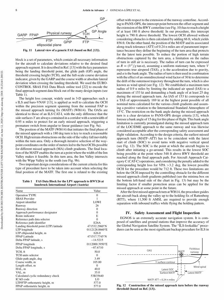
block is a set of parameters, which contain all necessary informationfor the aircraft to calculate deviations relative to the desired finalapproach segment. It is described inRef. [13]with the key parametersbeing the landing threshold point, the glide path (GP) angle, thethreshold crossing height (TCH), and the full-scale course deviationindicator, given by the GARP and the coursewidth or absolute lateraldeviation when crossing the landing threshold. We used the EURO-CONTROL SBAS FAS Data Block online tool [22] to encode thefinal approach segment data block out of the many design inputs (seeTable 1).The height loss concept, widely used in 3-D approaches such a
s ILS and baro-VNAV [13], is applied as well to calculate the OCHwithin the precision segment spanning from the nominal FAP tothe missed approach turning fix (MATF) (WI614). The OASs areidentical to those of an ILS CAT-I, with the only difference that theside surfacesY are always contained in a corridorwith a semiwidth of0.95 n miles to protect for an early missed approach, triggering apremature switch from angular to linear guidance (see Fig. 9a).The position of the MATF (WI614) that initiates the final phase of
the missed approach with a 180 deg turn is key to reach a reasonableOCH.High terrain obstructions on the side of thevalley fall inevitablywithin the turn area. Only a thorough iterative selection of the way-point coordinates on the order ofmeters led to the best OCHs possiblefor different missed approach (MA) climb gradients. The final loca-tion of theMATF enables the turn at a pointwhere thewidth of the InnValley makes it feasible. In this turn area, the Inn Valley intersectswith the Wipp Valley in the south (see Fig. 9b).Two important design considerations of the current criteria for this
type of procedure have to be taken into account when selecting thefinal position of the MATF. The first one is related to the existing
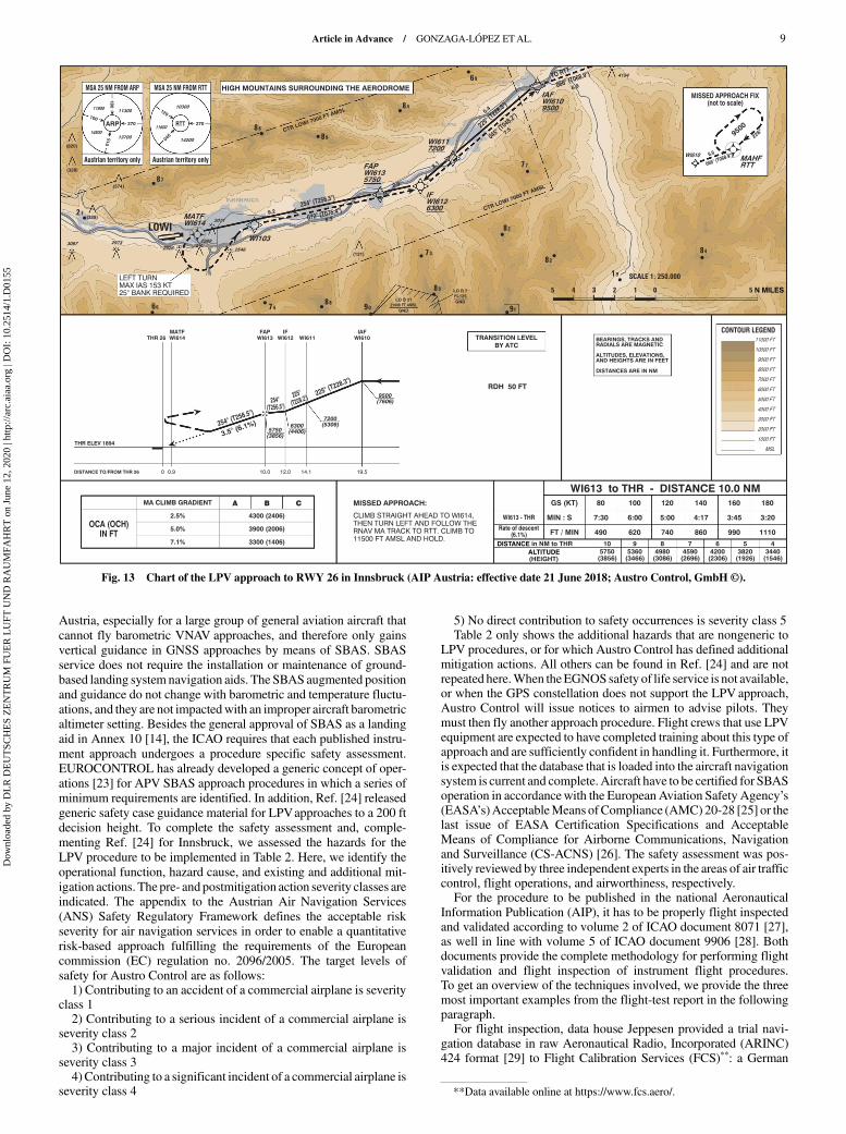
offset with respect to the extension of the runway centerline. Accord-ing to PANS-OPS, the intercept point between the offset segment andthe extension of theRWYcenterline (see Fig. 10) has to reach a heightof at least 180 ft above threshold. In our procedure, this interceptheight is 790 ft above threshold. The lowest OCH allowed withoutconsidering obstacles is then calculated by adding 66 ft, which yields856 ft. On the other hand, the position of theMATF and its associatedalong-track tolerance (ATT) of 0.24 n miles are of paramount impor-tance because they define the beginning of the turn area that protectsfor the latest turn possible. To reduce the portion of high terrainobstructions captured by the turn area, a limitation on the radiusof turn in still air is necessary. The radius of turn can be expressedas R � �V2∕g tan α�, assuming a uniform stationary turn, where Vrepresents true airspeed (TAS), g is the acceleration due to gravity,and α is the bank angle. The radius of turn is then used in combinationwith the effect of an omnidirectional wind factor of 30 kt to determinethe drift of the outermost trajectory throughout the turn, which is alsoknown as wind spiral (see Fig. 12). We established a maximum turnradius of 0.9 n miles by limiting the indicated air speed (IAS) to amaximum of 153 kt and demanding a bank angle of at least 25 degduring the missed approach turn. An IAS of 153 kt corresponds toa TAS of approximately 169 kt at the highest point possible of allnominal turns calculated for the various climb gradients and assum-ing a positive variation to the International Standard Atmosphere of15°C. The restriction on the bank angle during the missed approachturn is a clear deviation to PANS-OPS design criteria [13], whichforesee a bank angle of 15 deg for this phase of flight. This bank anglelimitation is currently promulgated during the missed approach turnof the LOC/DME approach to the same runway and was likewiseconsidered acceptable after the corresponding safety assessment andflight validation. According to the design criteria, the earliest missedapproach turn (MATF–ATT) has to be coincident with the lateststart of climb (SOC) to avoid turns with negative vertical speed(see Fig. 12). The SOC is the point at which the aircraft begins toclimb after initiating a go-around. This results in the lowest SOCbeing possible at the point where 548 ft above RWY threshold arereached along the final approach path. For Aircraft Approach Cat-egoryC (CAT-C) operations, and considering the penalty added to thecorresponding height loss for VPA >3.2 deg, the lowest possibleOCH for the procedure would be 712 ft. These two limitations arebelow the OCH imposed by the controlling obstacle for the differentmissed approach climb gradients published (see the minima box onthe bottom left-hand side of the chart in Fig. 13) but may be thelimiting factor if smaller protection areas can be applied for themissed approach at some point in the future.After the firstmissed approach turn atWI614, the procedureguides
the aircraft back along the valley up to the holding fix of Rattenberg(RTT), where 11,500 ft AMSL are required to provide enoughseparation with inbound traffics while flying the holding pattern.
IV. Safety Assessment and Flight Inspection
EGNOS is an extremely accurate navigation system. It is com-posed of satellites and ground stations that improve the accuracy ofthe Global Navigation Satellite System. The “ILS-lookalike” proce-dures can be seen as the most significant backup procedure for ILS in
Fig. 11 Lateral view of a generic FAS (based on Ref. [13]).
Table 1 FAS Data Block for the LPV approach to RWY26 atInnsbruck International Airport (Austria)
Name Value
Operation TYPE 0SBAS Provider 1Airport identifier LOWIRunway 26Runway direction 0Approach performance designator 0Route indicator EReference path data selector 0Reference path identifier E26ALanding threshold point (LTP) latitude 471532.2960°NLTP longitude 0112128.0660°ELTP ellipsoidal height, m 626.0FPAP Latitude 471517.7745°NDelta FPAP latitude, s −14.5215FPAP longitude 0112000.3950°EDelta FPAP longitude, s −87.6710TCH, ft 50.0TCH units selector 0Glide-path angle, deg 3.49Course width, m 105.00Length offset, m 0HAL, m 40.0VAL, m 35.0Calculated cyclic redundancy check 53B35640ICAO code LOLTP/FTP orthometric height, m 577.0FPAP orthometric height, m 577.0 Fig. 12 Construction of the missed approach turn before the runway
threshold (based on Ref. [13]).
8 Article in Advance / GONZAGA-LÓPEZ ETAL.
Dow
nloa
ded
by D
LR
DE
UT
SCH
ES
ZE
NT
RU
M F
UE
R L
UFT
UN
D R
AU
MFA
HR
T o
n Ju
ne 1
2, 2
020
| http
://ar
c.ai
aa.o
rg |
DO
I: 1
0.25
14/1
.D01
55
Austria, especially for a large group of general aviation aircraft thatcannot fly barometric VNAV approaches, and therefore only gainsvertical guidance in GNSS approaches by means of SBAS. SBASservice does not require the installation or maintenance of ground-based landing system navigation aids. The SBAS augmented positionand guidance do not change with barometric and temperature fluctu-ations, and they are not impactedwith an improper aircraft barometricaltimeter setting. Besides the general approval of SBAS as a landingaid in Annex 10 [14], the ICAO requires that each published instru-ment approach undergoes a procedure specific safety assessment.EUROCONTROL has already developed a generic concept of oper-ations [23] for APV SBAS approach procedures in which a series ofminimum requirements are identified. In addition, Ref. [24] releasedgeneric safety case guidance material for LPVapproaches to a 200 ftdecision height. To complete the safety assessment and, comple-menting Ref. [24] for Innsbruck, we assessed the hazards for theLPV procedure to be implemented in Table 2. Here, we identify theoperational function, hazard cause, and existing and additional mit-igation actions. The pre- andpostmitigation action severity classes areindicated. The appendix to the Austrian Air Navigation Services(ANS) Safety Regulatory Framework defines the acceptable riskseverity for air navigation services in order to enable a quantitativerisk-based approach fulfilling the requirements of the Europeancommission (EC) regulation no. 2096/2005. The target levels ofsafety for Austro Control are as follows:1) Contributing to an accident of a commercial airplane is severity
class 12) Contributing to a serious incident of a commercial airplane is
severity class 23) Contributing to a major incident of a commercial airplane is
severity class 34)Contributing to a significant incident of a commercial airplane is
severity class 4
5) No direct contribution to safety occurrences is severity class 5Table 2 only shows the additional hazards that are nongeneric to
LPV procedures, or for which Austro Control has defined additionalmitigation actions. All others can be found in Ref. [24] and are notrepeated here.When theEGNOSsafety of life service is not available,or when the GPS constellation does not support the LPV approach,Austro Control will issue notices to airmen to advise pilots. Theymust then fly another approach procedure. Flight crews that use LPVequipment are expected to have completed training about this type ofapproach and are sufficiently confident in handling it. Furthermore, itis expected that the database that is loaded into the aircraft navigationsystem is current and complete. Aircraft have to be certified for SBASoperation in accordancewith the EuropeanAviation Safety Agency’s(EASA’s)AcceptableMeans ofCompliance (AMC) 20-28 [25] or thelast issue of EASA Certification Specifications and AcceptableMeans of Compliance for Airborne Communications, Navigationand Surveillance (CS-ACNS) [26]. The safety assessment was pos-itively reviewed by three independent experts in the areas of air trafficcontrol, flight operations, and airworthiness, respectively.For the procedure to be published in the national Aeronautical
Information Publication (AIP), it has to be properly flight inspectedand validated according to volume 2 of ICAO document 8071 [27],as well in line with volume 5 of ICAO document 9906 [28]. Bothdocuments provide the complete methodology for performing flightvalidation and flight inspection of instrument flight procedures.To get an overview of the techniques involved, we provide the threemost important examples from the flight-test report in the followingparagraph.For flight inspection, data house Jeppesen provided a trial navi-
gation database in raw Aeronautical Radio, Incorporated (ARINC)424 format [29] to Flight Calibration Services (FCS)**: a German
N MILES
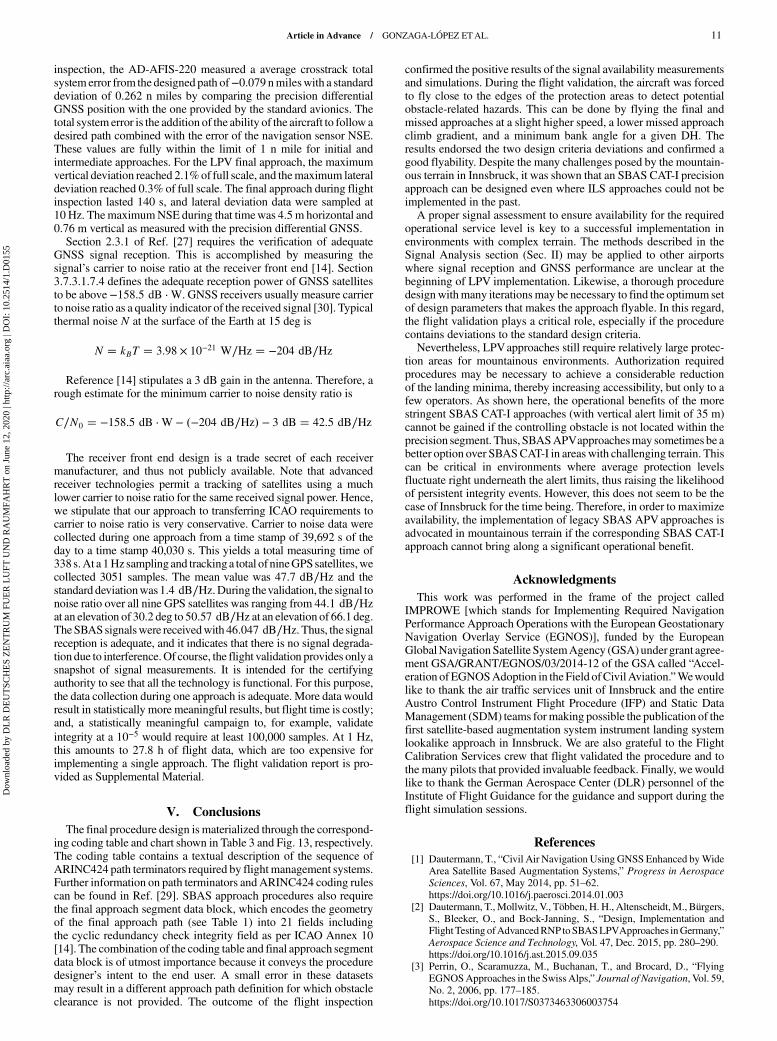
Fig. 13 Chart of the LPV approach to RWY 26 in Innsbruck (AIP Austria: effective date 21 June 2018; Austro Control, GmbH ©).
**Data available online at https://www.fcs.aero/.
Article in Advance / GONZAGA-LÓPEZ ETAL. 9
Dow
nloa
ded
by D
LR
DE
UT
SCH
ES
ZE
NT
RU
M F
UE
R L
UFT
UN
D R
AU
MFA
HR
T o
n Ju
ne 1
2, 2
020
| http
://ar
c.ai
aa.o
rg |
DO
I: 1
0.25
14/1
.D01
55

professional flight validation and inspection company. In the first stepof validation, FCS reviewed the received experimental navigationdatabase for potential codingmistakes that could have occurredwhentransferring AIP data into the specific ARINC424 database format.Here, it was found that the turn direction toward WI613 was missingfrom the coding, and a typographic error pertaining to the waypoint’scoordinates was discovered. This was consequently corrected by theprovider. Next, the database was loaded into the Aerodata AD-AFIS-220 flight inspection system of the flight inspection aircraft withregistration D-CFMD: a Beech 300 Super King Air 350. The Aero-data AFIS-220 calculates a precise reference position using a hybridsolution of barometric altitude, inertial platforms, and a precisiondifferential GNSS. The GNSS data were recorded at 1 Hz. Flightvalidation was successfully completed on 3 June 2017 from 1058 to
1119 hrs Universal Time Coordinated (UTC). Theweather was good,with variable wind direction and wind strength of 2 kt. Visibility wasmore than 10 km, scattered clouds were 7000 ft above the aerodrome,and the temperature was 26°C. Sea level pressure was 1015 hPa.Section 5.3 of Ref. [27] required the procedure navigation accuracy tobe verified according to procedure design requirements, as specifiedin Ref. [13]. The requirements are a required crosstrack navigationperformance (95% confidence interval) of 1 n mile in the initialand intermediate approach segments, and tapering to 0.3 n miles forthe final approach segment, where the angular guidance calculationbegins. For the final approach according to LPV, the total system errormay not exceed more than half of the full-scale deflection. Thenavigation sensor error (NSE) should not exceed the horizontal alertlimit of 40 m and the vertical alert limit of 35 m. During the flight
Table 2 Safety assessment table specific for the Innsbruck Airport
Function Hazard and cause Current risk minimizationWorst case operational
consequence SeveritySafetygoal
Additional riskminimization Postseverity
EGNOS signalinmountainousterrain
Loss of satellites/signal Quality assessment ofGPS/EGNOS signal
through simulations andmeasurements on site
Application of SBAS waspossible
Missed approach 4 —— N/A 4
Loss of GNSS/EGNOS signalduring finalapproach ormissedapproachphase
Troubles with GNSS orEGNOS signal; loss ofsatellites/jamming/
problems with equipment
Pilot should initiatecontingency procedure
radar vectoring—surveillance coverageavailable at all Austrian
airports
Use non-GNSSapproach
4 Nogreaterthanbefore
Safety recommendation:briefing ATCOs radarvectoring–in case the
aircraft is still at or abovethe MRVA/SMA
5
Proceduredesign
Two deviations fromICAO DOC 8168 [13]:minimum bank angle inthe missed approachgreater than 15 deg,
straight leg inintermediate segment less
than 2 n miles
Procedure properlyvalidated according toICAO DOC 9906 [28]
Minimum bank angle:aircraft gets outside
area for whichprocedure is not
protected Intermediatesegment: finalapproach course
wrongly intercepted
3 Nogreaterthanbefore
Safety recommendation,flight validation:
approach was positivelyevaluated in VMC,which endorsed
proposed design Safetyrecommendation,
intensive testing in anexperimental simulatorto discard flyabilityissues even under
extreme wind conditionssuccessful
4
Minima lineson thepublishedchart do notdistinguishbetween LPVor LPV200operations
Where both minimacriteria coexist, operators
may mix the systemminima, leading to asituation where a DH
below 250 ft is consideredfor LPV based on APV-I
criteria
Since published minimaby Austro Control in formof OCH are already equalto or greater than 250 ft forLPVapproaches based onAPV-I criteria at targetairports, there is no riskfor operators confusing
operating minima
Increased collision risk 4 Nogreaterthanbefore
N/A 4
N/A = not availableATCO = Air Traffic Control OfficerVMC = Visual Meteorological ConditionsAPV-1 = Approach Performance with Vertical guidance oneSMA = Surveillance Minimum Altitude
Table 3 Coding table used for LPV approach to RWY26 at Innsbruck International Airport (Austria)a
Point Leg Latitude Longitude Distance, n miles Course Altitude, ft Remarks
WI610 (IAF) IF N472322.41 E0114654.41 — — —— +9,500 ——
WI611 TF N471944.76 E0114055.80 5.4 T228.3 +7,200 ——
WI612 (IF) TF N471821.49 E0113838.95 2.1 T228.2 +6,300 ——
WI613 (FAP) TF N471753.55 E0113547.48 2.0 T256.5 +5,750 ——
WI614 (MATF) TF N471544.57 E0112242.29 9.2 T256.5 —— FlyoverWI103 (MATF) DF N471616.49 E0112647.56 — — —— —— IAS ≤ 153 kt ; bank ≥ 25 deg
WI612 (MATF) TF N471821.49 E0113838.95 8.3 T075.4 —— ——
WI610 (MATF) TF N472322.41 E0114654.41 7.5 T048.2 —— ——
RTT (MAHF) TF N472551.32 E0115624.19 6.9 T068.9 +11,500 Flyover
aThe navigation specification used is RNPAPCH.TF = Track to Fix, DF = Direct to Fix, and IF = Initial Fix.
10 Article in Advance / GONZAGA-LÓPEZ ETAL.
Dow
nloa
ded
by D
LR
DE
UT
SCH
ES
ZE
NT
RU
M F
UE
R L
UFT
UN
D R
AU
MFA
HR
T o
n Ju
ne 1
2, 2
020
| http
://ar
c.ai
aa.o
rg |
DO
I: 1
0.25
14/1
.D01
55
inspection, the AD-AFIS-220 measured a average crosstrack totalsystem error from the designed path of−0.079 nmileswith a standarddeviation of 0.262 n miles by comparing the precision differentialGNSS position with the one provided by the standard avionics. Thetotal system error is the addition of the ability of the aircraft to follow adesired path combined with the error of the navigation sensor NSE.These values are fully within the limit of 1 n mile for initial andintermediate approaches. For the LPV final approach, the maximumvertical deviation reached 2.1%of full scale, and themaximum lateraldeviation reached 0.3% of full scale. The final approach during flightinspection lasted 140 s, and lateral deviation data were sampled at10 Hz. ThemaximumNSE during that timewas 4.5 m horizontal and0.76 m vertical as measured with the precision differential GNSS.Section 2.3.1 of Ref. [27] requires the verification of adequate
GNSS signal reception. This is accomplished by measuring thesignal’s carrier to noise ratio at the receiver front end [14]. Section3.7.3.1.7.4 defines the adequate reception power of GNSS satellitesto be above−158.5 dB ⋅W. GNSS receivers usually measure carrierto noise ratio as a quality indicator of the received signal [30]. Typicalthermal noise N at the surface of the Earth at 15 deg is
N � kBT � 3.98 × 10⁻²¹ W∕Hz � −204 dB∕Hz
Reference [14] stipulates a 3 dB gain in the antenna. Therefore, arough estimate for the minimum carrier to noise density ratio is
C∕N0 � −158.5 dB ⋅W − �−204 dB∕Hz� − 3 dB � 42.5 dB∕Hz
The receiver front end design is a trade secret of each receivermanufacturer, and thus not publicly available. Note that advancedreceiver technologies permit a tracking of satellites using a muchlower carrier to noise ratio for the same received signal power. Hence,we stipulate that our approach to transferring ICAO requirements tocarrier to noise ratio is very conservative. Carrier to noise data werecollected during one approach from a time stamp of 39,692 s of theday to a time stamp 40,030 s. This yields a total measuring time of338 s.At a 1Hz sampling and trackinga total of nineGPSsatellites,wecollected 3051 samples. The mean value was 47.7 dB∕Hz and thestandard deviationwas1.4 dB∕Hz. During thevalidation, the signal tonoise ratio over all nine GPS satellites was ranging from 44.1 dB∕Hzat an elevation of 30.2 deg to 50.57 dB∕Hz at an elevation of 66.1 deg.TheSBASsignalswere receivedwith46.047 dB∕Hz. Thus, the signalreception is adequate, and it indicates that there is no signal degrada-tion due to interference.Of course, the flight validation provides only asnapshot of signal measurements. It is intended for the certifyingauthority to see that all the technology is functional. For this purpose,the data collection during one approach is adequate. More data wouldresult in statistically more meaningful results, but flight time is costly;and, a statistically meaningful campaign to, for example, validateintegrity at a 10−5 would require at least 100,000 samples. At 1 Hz,this amounts to 27.8 h of flight data, which are too expensive forimplementing a single approach. The flight validation report is pro-vided as Supplemental Material.
V. Conclusions
The final procedure design is materialized through the correspond-ing coding table and chart shown in Table 3 and Fig. 13, respectively.The coding table contains a textual description of the sequence ofARINC424 path terminators required by flightmanagement systems.Further information on path terminators andARINC424 coding rulescan be found in Ref. [29]. SBAS approach procedures also requirethe final approach segment data block, which encodes the geometryof the final approach path (see Table 1) into 21 fields includingthe cyclic redundancy check integrity field as per ICAO Annex 10[14]. The combination of the coding table and final approach segmentdata block is of utmost importance because it conveys the proceduredesigner’s intent to the end user. A small error in these datasetsmay result in a different approach path definition for which obstacleclearance is not provided. The outcome of the flight inspection
confirmed the positive results of the signal availability measurementsand simulations. During the flight validation, the aircraft was forcedto fly close to the edges of the protection areas to detect potentialobstacle-related hazards. This can be done by flying the final andmissed approaches at a slight higher speed, a lower missed approachclimb gradient, and a minimum bank angle for a given DH. Theresults endorsed the two design criteria deviations and confirmed agood flyability. Despite the many challenges posed by the mountain-ous terrain in Innsbruck, it was shown that an SBAS CAT-I precisionapproach can be designed even where ILS approaches could not beimplemented in the past.A proper signal assessment to ensure availability for the required
operational service level is key to a successful implementation inenvironments with complex terrain. The methods described in theSignal Analysis section (Sec. II) may be applied to other airportswhere signal reception and GNSS performance are unclear at thebeginning of LPV implementation. Likewise, a thorough proceduredesignwithmany iterationsmay be necessary to find the optimum setof design parameters that makes the approach flyable. In this regard,the flight validation plays a critical role, especially if the procedurecontains deviations to the standard design criteria.Nevertheless, LPVapproaches still require relatively large protec-
tion areas for mountainous environments. Authorization requiredprocedures may be necessary to achieve a considerable reductionof the landing minima, thereby increasing accessibility, but only to afew operators. As shown here, the operational benefits of the morestringent SBAS CAT-I approaches (with vertical alert limit of 35 m)cannot be gained if the controlling obstacle is not located within theprecision segment. Thus, SBASAPVapproachesmay sometimes be abetter option over SBASCAT-I in areas with challenging terrain. Thiscan be critical in environments where average protection levelsfluctuate right underneath the alert limits, thus raising the likelihoodof persistent integrity events. However, this does not seem to be thecase of Innsbruck for the time being. Therefore, in order to maximizeavailability, the implementation of legacy SBAS APVapproaches isadvocated in mountainous terrain if the corresponding SBAS CAT-Iapproach cannot bring along a significant operational benefit.
Acknowledgments
This work was performed in the frame of the project calledIMPROWE [which stands for Implementing Required NavigationPerformance Approach Operations with the European GeostationaryNavigation Overlay Service (EGNOS)], funded by the EuropeanGlobalNavigationSatellite SystemAgency (GSA)undergrant agree-ment GSA/GRANT/EGNOS/03/2014-12 of the GSA called “Accel-eration of EGNOSAdoption in theField ofCivilAviation.”Wewouldlike to thank the air traffic services unit of Innsbruck and the entireAustro Control Instrument Flight Procedure (IFP) and Static DataManagement (SDM) teams formaking possible the publication of thefirst satellite-based augmentation system instrument landing systemlookalike approach in Innsbruck. We are also grateful to the FlightCalibration Services crew that flight validated the procedure and tothe many pilots that provided invaluable feedback. Finally, wewouldlike to thank the German Aerospace Center (DLR) personnel of theInstitute of Flight Guidance for the guidance and support during theflight simulation sessions.
References
[1] Dautermann, T., “Civil Air Navigation Using GNSS Enhanced byWideArea Satellite Based Augmentation Systems,” Progress in Aerospace
Sciences, Vol. 67, May 2014, pp. 51–62.https://doi.org/10.1016/j.paerosci.2014.01.003
[2] Dautermann, T.,Mollwitz, V., Többen, H. H., Altenscheidt,M., Bürgers,S., Bleeker, O., and Bock-Janning, S., “Design, Implementation andFlightTesting ofAdvancedRNPtoSBASLPVApproaches inGermany,”Aerospace Science and Technology, Vol. 47, Dec. 2015, pp. 280–290.https://doi.org/10.1016/j.ast.2015.09.035
[3] Perrin, O., Scaramuzza, M., Buchanan, T., and Brocard, D., “FlyingEGNOSApproaches in the SwissAlps,” Journal of Navigation, Vol. 59,No. 2, 2006, pp. 177–185.https://doi.org/10.1017/S0373463306003754
Article in Advance / GONZAGA-LÓPEZ ETAL. 11
Dow
nloa
ded
by D
LR
DE
UT
SCH
ES
ZE
NT
RU
M F
UE
R L
UFT
UN
D R
AU
MFA
HR
T o
n Ju
ne 1
2, 2
020
| http
://ar
c.ai
aa.o
rg |
DO
I: 1
0.25
14/1
.D01
55

[4] Troller, M., Scaramuzza, M., Truffer, P., Wipf, H., and Raemi, S.,“Performance Impact of Mountainous Topography for Cloud BreakGNSS Procedure,” Proceedings of the 25th International Technical
Meeting of the Satellite Division of the Institute of Navigation (ION
GNSS2012), The Institute ofNavigation,Manassas,VA, 2012, pp. 203–209.
[5] “Aeronautical Information Publication,”U.S. Terminal Procedures Pub-lication, U.S. Dept. of Transportation. Federal Aviation Administration,April 2019.
[6] Aeronautical Information Publication Norway, effective date 28 March2019, Avinor, 2019.
[7] “Aeronautical Information Publication France,” French General Direc-torate of Civil Aviation, April 2019.
[8] “Aeronautical Information Publication Switzerland,” Skyguide, April2019.
[9] Performance-Based Navigation Manual, 4th ed., International CivilAviation Organization Doc 9613, Montreal, 2012.
[10] Forssell, B., Radionavigation Systems. GNSS Technology andApplications Series, Artech House, Norwood, MA, 2008.
[11] EGNOS Safety of Life (SoL) Service Definition Document, EuropeanGNSS Agency, 3.2 ed., 2018.
[12] “Annex 6 to the Convention on International Civil Aviation: Operationof Aircraft, Pt. 1, International Commercial Air Transport–Aeroplanes,International Civil Aviation Organization, Montreal, 2016.
[13] “Procedures for Air Navigation Services—Aircraft Operations,”Vol. 2,Construction of Visual and Instrument Flight Procedures (incorporatingAmendment No. 7), 6th ed., International Civil Aviation OrganizationDoc 8168, Montreal, 2016.
[14] Annex 10 to the Convention on International Civil Aviation: Aeronaut-ical Telecommunications Vol. 1, Radio Navigation Aids, 2006.
[15] “Minimum Operational Performance Standards for Global PositioningSystem/WideAreaAugmentation SystemAirborne Equipment,”RTCASTD DO-229D, Washington, D.C., 2006.
[16] Jan, S. S., Chan, W., and Walter, T., “MATLABAlgorithm AvailabilitySimulation Tool,” GPS Solutions, Vol. 13, No. 4, 2009, pp. 327–332.https://doi.org/10.1007/s10291-009-0117-4
[17] NAVSTAR GPS Space Segment/Navigation User Interfaces, UnitesStates Air Force, IS-GPS-200 Revision J, 2018.
[18] Takasu, T., and Yasuda, A., “Development of the Low-Cost RTK-GPSReceiver with an Open Source Program Package RTKLIB,”International Symposium on GPS/GNSS, 2009, pp. 4–6.
[19] Renfro, B. A., Stein, M., Boeker, N., Reed, E., and Villalba, E., “AnAnalysis of Global Positioning System (GPS) Standard PositioningService (SPS) Performance for 2018,” Space and Geophysics Lab.,AppliedResearchLab.,Univ. ofTexas atAustin TR-SGL-19-02,Austin,TX, 2019.
[20] Walter, T., Hansen, A., and Enge, P., “Validation of the WAAS MOPSIntegrity Equation,” Proceedings of the 55th Annual Meeting of The
Institute of Navigation, The Institute of Navigation,Manassas, VA, June1999, pp. 217–226.
[21] Christian, H., “Digital Terrain Models,” Encyclopedia of Geodesy,Springer International, New York, 2014, pp. 1–6.
[22] SBAS FAS Data Block Tool, Ver. 3.1.0, Software Package, EUROCON-TROL,Brussels, 2017, https://fasdb.eurocontrol.int/fasdb/app/about.htm[retrieved April 2017].
[23] APV SBAS Approach—Concept of Operations—Edition 1.0 EURO-CONTROL, 2009.
[24] Safety Case GuidanceMaterial for Deployment of SBASCAT I Edition2.0 Accepta Project, 2017.
[25] “Airworthiness Approval and Operational Criteria Related to AreaNavigation for Global Navigation Satellite SystemApproachOperationto Localiser Performance with Vertical Guidance Minima Using Satel-lite Based Augmentation System. European Aviation Safety AgencyAMC 20-28, 2012.
[26] Certification Specifications and Acceptable Means of Compliance forAirborne Communications, Navigation and Surveillance (CS-ACNSIssue 2), European Aviation Safety Agency EASA, 2019.
[27] Manual on Testing of Radio Navigation Aids Vol. 2—Testing ofSatellite-Based Radio Navigation Systems, 5th ed., International CivilAviation Organization Doc. 8071, Montreal, 2007.
[28] Quality Assurance Manual for Flight Procedure Design Volume5—Validation of Instrument Flight Procedures, 1st ed., InternationalCivil Aviation Organization Doc 9906, Montreal, 2012.
[29] Navigation System Database—ARINC 424-21, Aeronautical Radio,Inc., 2016.
[30] Falletti, E., Pini,M., andPresti, L. L., “LowComplexityCarrier-to-NoiseRatio Estimators for GNSS Digital Receivers,” IEEE Transactions on
Aerospace and Electronic Systems, Vol. 47, No. 1, 2009, 420–437.
H. IdrisAssociate Editor
12 Article in Advance / GONZAGA-LÓPEZ ETAL.
Dow
nloa
ded
by D
LR
DE
UT
SCH
ES
ZE
NT
RU
M F
UE
R L
UFT
UN
D R
AU
MFA
HR
T o
n Ju
ne 1
2, 2
020
| http
://ar
c.ai
aa.o
rg |
DO
I: 1
0.25
14/1
.D01
55