implementing x plane as a visual system for a research
TRANSCRIPT

Master’s Thesis
Implementing X–Plane as a VisualSystem for a Research Flight Simulator
submitted by
Thomas Krajacic
for achieving the academic title of Diplom–Ingenieurin the field of Mechanical Engineering and Economics/Mechatronics.
————————————–
Institute of MechanicsGraz University of Technology
Advisor: Ao.Univ.-Prof. Dipl.-Ing.Dr.techn. Reinhard BraunstinglGraz, March 2012

Abstract
The Institute of Mechanics at the University of Technology in Graz employs a researchplatform for flight simulation, which includes a flight simulator featuring a projection domefor visualizing the environment. Presently, Microsoft Flightsimulator X is being utilized todraw the outside world for the simulator. The product of this thesis is to be implementedas part of an improved visual system in a second simulator currently being built (March2012). This thesis is also intended to serve as a foundation for future academic projectsaimed at improving the visual quality of simulation.
This paper describes how the PC flight simulation software X–Plane was connected tothe FGED flight simulator (Flight, Gear and Engine Dynamics — the custom built simu-lation software created at the Institute of Mechanics) by developing a plugin for X–Planeand a shared library using the C++ programming language. Fundamental knowledgeof coordinate systems and transformation as well as advanced computer programmingconcepts like shared memory and dynamic libraries were applied to integrate the FGEDflight simulator and X–Plane.
The first two chapters provide an overview over visual systems for flight simulationand explain different methods to describe position and attitude of an aircraft as well ashow to apply transformations between coordinate systems — an essential requirement inflight simulation.
Chapter 3 details the process of structuring the project and developing and implement-ing a solution. After an introduction to programming topics such as using shared memoryand creating dynamically loaded shared libraries, the chapter shows how to develop anX–Plane plugin which fetches and uses the information about the position and attitude ofthe aircraft, and how X–Plane can report back information like frame rate and groundelevation.
The final chapter reviews the implemented features, analyzes the performance of theimplemented solution, and discusses future improvements to be made.
The Appendix includes a User’s Guide and a Developer’s Guide as well as a listing ofthe complete source code. The User’s Guide provides information about how to installand configure the finished product, gives a specification of features and known limitations,or references them as far as they have been mentioned in the main thesis. The Developer’sGuide gives details on how to set up a development environment to continue developmentand supplies helpful information on certain implementation specific aspects of the solutiondeveloped in this paper.

Kurzfassung
Das Institut für Mechanik an der Technischen Universität in Graz betreibt eineForschungsplattform für Flugsimulation und verfügt über einen Flugsimulator, dessen Sicht-system mit einer kugelschalenförmigen Projektionswand ausgestattet ist. Die Darstellungder Aussenwelt wird zur Zeit durch die Software Microsoft Flightsimulator X gewährleistet.Ein zweiter Simulator befindet sich gerade im Bau, und das Ergebnis dieser Arbeit soll imSichtsystem dieses Simulators implementiert werden. Dadurch soll ein höherer Grad anRealismus in der Darstellung erreicht, sowie die Möglichkeit geschaffen werden, aufbauendauf dieser Arbeit, weitere Projekte im universitären Rahmen an Studenten zu vergeben.
Die vorliegende Arbeit beschreibt, wie die PC–Software X–Plane in den FGEDSimulator (Flight, Gear and Engine Dynamics — der auf dem Mechanik Institut derTU Graz selbst entwickelte Flugsimulator) integriert wurde, indem ein X–Plane Pluginund eine C++ Bibliothek entwickelt wurden. Grundlegendes Wissen über Koordinaten-systeme und -transformationen, sowie tiefgreifendes Verständnis im Bereich der Computer–Programmierung über Themen wie Shared Memory und dynamische Bibliotheken wurdenangewandt um X–Plane in den bestehenden Simulator zu integrieren.
Die ersten beiden Kapitel bieten eine Übersicht über Sichtsysteme in der Flugsimulationund die wichtigsten Technologien, die darin angewandt werden. Weiters werden diegebräuchlichsten, in der Flugsimulation verwendeten, Koordinatensysteme vorgestellt,Methoden, wie man die Lage eines Flugzeugs beschreiben kann und wie man Koordinatenin unterschiedliche Bezugssysteme transformieren kann — eine wichtige Voraussetzung fürBerechnungen im Rahmen der Flugsimulation.
Kapitel 3 beschäftigt sich ausführlich mit der strukturierten Entwicklung der Lösungund den Details der Implementierung. Nach einer kurzen Einführung in die Verwendungvon dynamischen Bibliotheken und Shared Memory wird gezeigt, wie man für X–Plane einPlugin entwickelt, welches Informationen über Ort und Lage eines Flugzeugs empfängt,X–Plane entsprechend steuert, und Frame Rate und Höhe des Untergrunds zurückliefert.
Im letzten Kapitel werden die implementierten Funktionen untersucht sowie die Leis-tungsfähigkeit der entwickelten Lösung analysiert. Weiters werden mögliche zukünftigeVerbesserungen und Erweiterungen des Systems diskutiert.
Im Anhang befinden sich ein Benutzerhandbuch und ein Entwicklerhandbuch. DasBenutzerhandbuch gibt Information darüber, wie man alle Komponenten der Lösunginstalliert und konfiguriert, welche Funktionen verfügbar sind, und welche Beschränkungenbestehen. Bei Bedarf wird auf die entsprechenden Passagen im Hauptteil der Arbeitverwiesen. Das Entwicklerhandbuch beschreibt, wie man eine Entwicklungsumgebung fürdie Weiterentwicklung dieses Projekts vorbereitet und gibt hilfreiche Informationen zueinigen Aspekten der Programmierung in dieser Arbeit.

STATUTORY DECLARATION
I declare that I have authored this thesis independently, that I have not used other thanthe declared sources / resources, and that I have explicitly marked all material which hasbeen quoted either literally or by content from the used sources.
.............................. ...........................................date (signature)

Acknowledgements
First and foremost I would like to express my gratitude to Professor Braunstingl, who’slectures on flight simulation I have enjoyed and who inspired my interest in working withthe flight simulator at the university. He also supported me during the course of writingthis thesis.
Special thanks go to Sandy Barbour IEng MIET, co-author of the plugin SDK forX–Plane, for providing exceptional support despite being very busy due to the upcomingrelease of the next version of X–Plane. Even though Mr. Barbour is doing developmenton the SDK in his spare time, he not only responded to my posts on one of the developerforums, but also kindly provided personal assistance via email with regard to a number ofquirks uncovered while programming with the SDK — most of which where based on myinexperience rather than flaws of the SDK or X–Plane.
Further, Mr. Barbour and Mr. Ben Supnik, the second developer on the SDK, deservespecial recognition for even providing the SDK for X–Plane (Mr. Barbour is not evenemployed by Laminar Research, both develop the SDK in their spare time without beingpaid for it, and yet they make it available for free to the public). The solution developedin this thesis would not have been possible without their work.
A ‘Thank you!’ is also in order for the many people who answered my questions onthe http://forums.x-plane.org/ forum. Without the help of this community, it would havebeen a lot harder to start developing a plugin for X–Plane.

Table of Contents
1 Introduction 11.1 Motivation . . . . . . . . . . . . . . . . . . . . . . . . . . . . . . . . 11.2 Overview of Visual System Technology . . . . . . . . . . . . . . . . 41.3 Visual System Software . . . . . . . . . . . . . . . . . . . . . . . . . 61.4 Goals . . . . . . . . . . . . . . . . . . . . . . . . . . . . . . . . . . . 8
2 Theory 92.1 Common Coordinate–Systems in Aviation . . . . . . . . . . . . . . 9
2.1.1 Earth–Centered–Earth–Fixed (ECEF) . . . . . . . . . . . . 102.1.2 North–East–Down (NED) . . . . . . . . . . . . . . . . . . . 122.1.3 Body–fixed Coordinate System . . . . . . . . . . . . . . . . 122.1.4 X–Plane’s OpenGl Coordinate Space . . . . . . . . . . . . . 13
2.2 Describing Aircraft Attitude . . . . . . . . . . . . . . . . . . . . . . 142.3 Coordinate Transformations . . . . . . . . . . . . . . . . . . . . . . 15
2.3.1 Rotation Matrix / Euler–angles . . . . . . . . . . . . . . . . 152.3.2 Quaternions / Euler–Rodrigues Parameters . . . . . . . . . . 192.3.3 Comparison of Rotation Formulations . . . . . . . . . . . . . 23
3 Implementation 243.1 Existing Interface . . . . . . . . . . . . . . . . . . . . . . . . . . . . 263.2 Designing a New Solution (FGED–link) . . . . . . . . . . . . . . . . 283.3 Shared Library (FGEDBridge) . . . . . . . . . . . . . . . . . . . . . 29
3.3.1 Shared Memory . . . . . . . . . . . . . . . . . . . . . . . . . 313.3.2 JNI Interface . . . . . . . . . . . . . . . . . . . . . . . . . . 353.3.3 C/C++ Interface . . . . . . . . . . . . . . . . . . . . . . . . 38
3.4 X–Plane Plugin (FGEDCommander) . . . . . . . . . . . . . . . . . 393.4.1 Anatomy of an X–Plane Plugin . . . . . . . . . . . . . . . . 39
MASTER’S THESIS - THOMAS KRAJACIC vi

TABLE OF CONTENTS Table of Contents
3.4.2 Setting and Getting X–Plane Parameters . . . . . . . . . . . 423.4.3 Aircraft Control . . . . . . . . . . . . . . . . . . . . . . . . . 453.4.4 Changing Aircraft Models . . . . . . . . . . . . . . . . . . . 463.4.5 View Configuration . . . . . . . . . . . . . . . . . . . . . . . 493.4.6 Adjusting Weather . . . . . . . . . . . . . . . . . . . . . . . 533.4.7 Setting Date and Time . . . . . . . . . . . . . . . . . . . . . 553.4.8 Sending Return Values . . . . . . . . . . . . . . . . . . . . . 56
4 Conclusion 574.1 Feature Analysis . . . . . . . . . . . . . . . . . . . . . . . . . . . . 584.2 Shortcomings of the Current Implementation . . . . . . . . . . . . . 594.3 Performance Analysis . . . . . . . . . . . . . . . . . . . . . . . . . . 60
4.3.1 XPInterface . . . . . . . . . . . . . . . . . . . . . . . . . . . 614.3.2 X–Plane . . . . . . . . . . . . . . . . . . . . . . . . . . . . . 614.3.3 FGED–link . . . . . . . . . . . . . . . . . . . . . . . . . . . 62
4.4 Possible Future Features . . . . . . . . . . . . . . . . . . . . . . . . 65
Appendix 66
A User’s Guide 67A.1 FGED–link Installation . . . . . . . . . . . . . . . . . . . . . . . . . 67A.2 X–Plane Setup . . . . . . . . . . . . . . . . . . . . . . . . . . . . . 69
A.2.1 The Configuration File . . . . . . . . . . . . . . . . . . . . . 69A.2.2 X–Plane Settings . . . . . . . . . . . . . . . . . . . . . . . . 70A.2.3 Performance Tuning . . . . . . . . . . . . . . . . . . . . . . 73
A.3 JNI Interface Reference . . . . . . . . . . . . . . . . . . . . . . . . . 74A.3.1 renderEngineXfr(...) . . . . . . . . . . . . . . . . . . . 75A.3.2 setUserAircraft(...) . . . . . . . . . . . . . . . . . . . 75A.3.3 calibrateView(...) . . . . . . . . . . . . . . . . . . . . . 75A.3.4 setAircraft(...) . . . . . . . . . . . . . . . . . . . . . . 76A.3.5 setCamera(...) . . . . . . . . . . . . . . . . . . . . . . . . 76A.3.6 setWeather(...) . . . . . . . . . . . . . . . . . . . . . . . 77A.3.7 setDateTime(...) . . . . . . . . . . . . . . . . . . . . . . 77A.3.8 setPilotsHead(...) . . . . . . . . . . . . . . . . . . . . . 78A.3.9 getAircraftModels() . . . . . . . . . . . . . . . . . . . . 78A.3.10 getReturnValues(...) . . . . . . . . . . . . . . . . . . . 78
MASTER’S THESIS - THOMAS KRAJACIC vii

TABLE OF CONTENTS Table of Contents
B Developer’s Guide 79B.1 Development notes . . . . . . . . . . . . . . . . . . . . . . . . . . . 79B.2 Setting Up the Environment . . . . . . . . . . . . . . . . . . . . . . 80
B.2.1 The Qt Libraries . . . . . . . . . . . . . . . . . . . . . . . . 81B.2.2 Project Setup in Visual Studio 2010 . . . . . . . . . . . . . . 82
B.3 Class Overview . . . . . . . . . . . . . . . . . . . . . . . . . . . . . 85B.3.1 The Aircraft Class . . . . . . . . . . . . . . . . . . . . . . . 85B.3.2 The Environment Class . . . . . . . . . . . . . . . . . . . . 86B.3.3 The FGEDHelper Namespace . . . . . . . . . . . . . . . . . 86
List of Figures 87
List of Tables 89
List of Code–Listings 90
Bibliography 91
Where a masculine term may appear in this paper it refers to both sexes.
MASTER’S THESIS - THOMAS KRAJACIC viii

Chapter 1
Introduction
There are many aspects of simulating flight, and the most basic requirement is thesimulation of physical phenomena like gravity, lift or drag. This may be enough forengineering applications like testing airframe behavior or manifestation of aircraft failures.If, however, the intent is to induce the feeling of actually commanding a real aircraft,then one of the most important components will be a visual representation of the pilot’senvironment. This not only includes the cockpit but also the world outside the aircraft.
The subject of this thesis is the integration of X–Plane into the FGED flight simulator(Flight, Gear and Engine Dynamics — the custom built simulation software createdat the Institute of Mechanics), to provide an exceptional visual representation of theenvironment. Chapter 1 presents the motivation for switching to X–Plane and gives ashort introduction to visual systems in general, their history and the core technologiesthey utilize. It concludes on the goals that were set for the solution developed in thispaper. Chapter 2 introduces the reader to the concepts of different coordinate systems,transformation between them and mathematical ways to describe them. The followingChapter 3 gives a detailed look at how the desired features were carried out, and Chapter 4analyzes to which extent they were implemented, takes a look at performance and discussesways to further enhance the product of this thesis. The Appendix includes a User’s Guideexplaining how to install and set up the finished product and a Developer’s Guide givinginformation on how to continue development for it.
1.1 Motivation
Flight simulator I at the Institute of Mechanics at the University of Technology in Graz(TU Graz) is equipped with a replica hull of a DC–10 cockpit and a spherical projectionwall with three projectors for visualizing the environment. It covers a horizontal field ofview of about 150◦ and a vertical field of view of about 33◦. The projection wall is roughly5 meters in front of the pilot, which, even though not optimal, provides good conditionsconcerning distant focus (see section 1.2 about collimation). The FGED flight simulatorcurrently uses Microsoft’s Flightsimulator X (FSX) in its visual system.
MASTER’S THESIS - THOMAS KRAJACIC 1

CHAPTER 1. INTRODUCTION Motivation
Figure 1.1: Flight simulator I at the TU Graz. Three projectors displaythe virtual world on a spherical wall with an approximate horizontal field ofview of 150◦ and a vertical field of view of about 33◦. The projection wall isapproximately 5 meters in front of the pilot. Photo courtesy of Dipl. Ing. Boris-André Prehofer. All rights reserved.
A second simulator with a cylindrical projection wall is in the final stage of construction(March 2012). Its projection wall is about 3.5 meters in front of the pilot and providesa horizontal and vertical field of view of approximately 180◦ and 44◦, respectively. Theproduct of this thesis is intended to be implemented there to create an improved visualsystem that provides the foundation for future academic projects and further enhancingvisual quality in simulation (figure 1.2).
Using FSX as image generator worked well for many years, but it has its limitations.The library used to connect FSX and FGED is a commercial product (FSUIPC by PeterDowson1) and its source code is not available, which makes it impossible to add or improvefeatures as needed. Furthermore, the visual quality of the virtual world is starting to showits age. Computer graphics technology has advanced a lot in recent years and FSX has not1http://www.schiratti.com/dowson.html
MASTER’S THESIS - THOMAS KRAJACIC 2

CHAPTER 1. INTRODUCTION Motivation
Figure 1.2: The unfinished Flight simulator II at the TU Graz. The cylindricalprojection wall has an approximate horizontal field of view of 180◦ and a verticalfield of view of around 44◦. The projection wall will be approximately 3.5 metersin front of the pilot.
been improved in a long time2, its development has even been officially abandoned in 20093.In August 2010 Microsoft announced it would release a completely new flight simulationplatform called Microsoft Flight4, but no release date was given, nor any informationwhether a plugin–system or software developer kit (SDK) of the necessary level wouldeven be available.
On the other hand, Laminar Research, the maker of X–Plane have been busy workingon the next version (X–Plane 10 ). Its release was already delayed more than a year frominitial plans, but X–Plane 10 was finally released in December 2011. Furthermore, apowerful SDK is available for X–Plane. The plugin SDK is an independent developmentto allow programmers to create plugins that can be used with X–Plane. It is developedby Sandy Barbour and Ben Supnik in their spare time, and made available free of charge.
While X–Plane 9 already provided very good graphics and a powerful SDK, the releaseof version 10 further enhanced possibilities for some of the desired features.
Originally, the work in this thesis was done with X–Plane 9 but the SDK had a historyof providing consistent features throughout multiple releases of X–Plane and so whenX–Plane 10 was released only minor modifications to the source code were necessaryfor the switch to the latest version. The version of X–Plane 10 used in this thesis was10.0.4r1, which, although released already, was still considered beta software, and somenew features were not yet accessible through the SDK (e.g. the new cirrus cloud type).Therefore, some of the work in this paper might need adjustments once X–Plane matures.2Flightsimulator X was released in October 2006.3See http://www.microsoft.com/Products/Games/FSInsider/news/Pages/AMessageFromAces.aspx4http://www.microsoft.com/games/flight/
MASTER’S THESIS - THOMAS KRAJACIC 3

CHAPTER 1. INTRODUCTION Overview of Visual System Technology
1.2 Overview of Visual System Technology
This section aims to give a short overview of the history of visual systems and mentionssome important technologies used. The historic information presented here was takenmostly from Page and Associates [22].
Figure 1.3: The analog visual system of the TL39 flight simulator used twoterrain mock–ups and two cameras. It was installed at the Moscow AviationInstitute until 2001. Source: Wikipedia, Photo by Sergey Khantsis.
In the early days of flight simulation (at the beginning of the 20th century) differentmethods of giving the pilot a better understanding of the environment were invented. Avery simple method in the 1950s was the projection of shadows of objects with a point–lightsource onto a backlit screen, to give a hint of what the environment could look like. Inthe same time period, systems were developed where pre–recorded movies were projectedor displayed on a monitor in front of the pilot. Later, even closed circuit images weretransferred from a camera that moved over a model scene of the environment according tothe flightpath chosen by the pilot (see figure 1.3). Of course, the obvious limitation ofthese systems restricted the aircraft’s movement to the very limited area that was modeled.
MASTER’S THESIS - THOMAS KRAJACIC 4

CHAPTER 1. INTRODUCTION Overview of Visual System Technology
The biggest advances became possible through the evolution of digital computers andcomputer graphics technology. CRT Monitors and projectors could be used to displaythe environment using computer generated images capable of presenting scenery with ahigher degree of detail. Monitors (though mostly LCDs) and projectors are still usedtoday, although they are frequently combined with collimating mirrors (see below) forenhanced realism.
One of the challenges in providing a realistic experience with a monitor or projectionscreen close to the pilot is the presentation of objects supposed to be far away, while they infact are being projected at a very close distance. This does not provide the same impressionas viewing a distant object in real life. Since the human brain creates three–dimensionalimages by combining what both eyes see, depth perception is very strong at close distancesbut quite weak to non–existent at greater distances, as the images seen by both eyes showmore or less the same angle of an object. This effect is especially noticeable at distancesof less than approximately 9 meters.
Monitor Projector
Beam sp
litter
Sphericalprojection screen
Sphericalmirror
Sphericalmirror
Figure 1.4: Through collimation it is possible to make the eyes focus at‘optical infinity’, which in turn lets the brain believe that the image seen is at adistance. The left schematic shows the use of a monitor and a semi–reflectivebeam splitter. In the right image a projector and a spherical projection screenare used.
To achieve the same effect for images that are displayed close to the pilot, the visuallines need to be collimated (see figure 1.4). This means that the visual lines arriveparallelized at the eye or, the other way around, the eye is impelled to focus at ‘opticalinfinity’. That way the brain assumes the relevant object to be far away. Technically, thiscan be achieved using parabolic reflective mirrors. Since parabolic mirrors would be verydifficult and expensive to produce with the required accuracy, spherical mirrors are usedinstead, which match the parabolic shape in the vicinity of its vertex very closely.
A second very important effect achieved by collimated displays is that a pilot and aco–pilot sitting in a simulator cockpit do not experience the parallax error that is present
MASTER’S THESIS - THOMAS KRAJACIC 5

CHAPTER 1. INTRODUCTION Visual System Software
with regular projection onto a wall or screen. Suppose the pilot is looking straight aheadto view an object at the end of the runway. This object would need to be displayed on theprojection wall in front of the pilot. The co–pilot, however, would also expect this objectto be directly in front of him, but it is actually displayed to the left — where the pilotwould need to see it on the projection wall (see figure 1.5).
pilot co-pilot
ε
proj
ectio
n wall
where distant objects are displayed (calibrated for pilot)
where co-pilot would expect to see distant objects
pilot co-pilotco
llim
ating m
irror
where pilot sees distant objects
where co-pilot sees distant objects
Figure 1.5: Since the pilot expects distant objects straight ahead to beprojected directly in front of him, the projection display needs to be calibratedto do so. This creates a parallax error for the co-pilot in the simulator as hewould also expect that same distant object to be projected directly in front ofhim. The angular error ε is called parallax error. This effect is remedied byusing a collimating mirror.
Modern simulators achieve this with a collimating mirror which is frequently a thinreflective film (for example aluminized Mylar) that is shaped through a partial vacuumon the back side. This makes the construction extremely light and it is cheaper thanproducing highly accurate mirrors out of rigid materials.
While the hardware can contribute to a reaslitic experience mostly with collimationand an unrestrained field of view, the degree of realism depends heavily on the softwareresponsible for drawing the outside world.
1.3 Visual System Software
It is no trivial task to create a computerized representation of the environment, be itjust for the sheer amount of data to process. Modeling a realistic environment to fly inrequires information about ground elevation, the type of terrain (like grass, trees, water),placement of roads and buildings, and so on. Since it should also be a representationof the real world and not just a fictitious area, it is further not simply sufficient togenerate random scenery, but information about the real world would have to be gatheredfrom numerous sources. Furthermore, to provide a high degree of realism, it is required
MASTER’S THESIS - THOMAS KRAJACIC 6

CHAPTER 1. INTRODUCTION Visual System Software
that atmospheric phenomena like clouds, rain or lightning can be simulated convincingly.Displaying additional aircraft traffic on airports and in the sky gives the benefit of furtherimproving the simulation of real world situations.
The visual system needs to be capable of displaying these details at a frame rate highenough for the human eye to interpret motion between the images as fluid. Multiple factorscontribute to this and aside from the physiological differences among human individuals,the speed of the content in the consecutive images, the size of the display, brightness ofthe images, and other factors are important. While it is not possible to give a definiteframe rate (the human eye does not see in ‘frames’), the frame rate to trick the brain intobelieving that consecutive images show continuous motion without any difference to thereal world is very high — probably in excess of 300 frames per second (fps) [1, 5]. Forvisual systems (especially for non–combat aircraft simulators) however, a frame rate of60–100fps is common, since relative motion of objects seen outside the cockpit is relativelylow. Even 30fps have given acceptable results with the flight simulator at the TU Graz.
Summing up all the software requirements for visual systems, it proves to be beyondthe capacities of small simulator–developers to provide a visualization of the entire worldor even a larger area like a whole country, so alternatively it is a viable option to purchaseand integrate a third–party visual system.
There are quite a few manufacturers of visual systems offering products for differentrequirements concerning technology and realism. Table 1.1 lists a few companies and linksto their product websites.
FRASCA http://www.frasca.com/products/visualsystems.php
Lockheed Martin http://www.sim-industries.com/visual-system/
RSI visual systems http://www.rsi-visuals.com/
FlightSafety http://www.flightsafety.com/fs_service_simulation_systems_cat.php?p=vis
CAE http://www.cae.com/en/sim.products/sim.products.asp
Evans & Sutherland http://www.es.com/
Table 1.1: A list of selected visual system suppliers for flight simulators.
With most suppliers, it is possible to acquire just the image generator, or a completeproduct including screen(s) or projection hardware. According to the information pre-sented on these websites, the high–end products are suited for even the most demandingapplications.
A certainly less expensive alternative is provided through PC–flight simulators likeMicrosoft Flightsimulator 5 or X–Plane6, which already include a modeled environmentthat spans most of the globe and is detailed enough for a realistic experience. These5http://www.microsoft.com/games/flightsimulatorx/6http://www.x-plane.com/
MASTER’S THESIS - THOMAS KRAJACIC 7

CHAPTER 1. INTRODUCTION Goals
simulators allow for being used as visual system software through a programming interfacewhich in turn creates the additional benefit of providing many opportunities for studentsto work on projects and study topics related to flight simulation.
1.4 Goals
When deciding on requirements for a future visual system, the following goals were set,regardless of what could be done with the X–Plane SDK’s features:
1© Seamless integration into the current system while keeping the same interface.This includes being able to set position and attitude as well as the weather, andgetting the frame rate and local ground elevation back in return. See table 3.1on page 27 for a complete list of the original interface’s parameters.
2© Support for a setup of three or more projectors as seen in figure 3.1.
3© A possibility to control and display a number of additional aircraft in simulation.
4© More realistic rendering of lights. Especially the aircraft’s lighting in FSX wasbelow expectations. Realistic landing lights and strobes illuminating cloudswhen flying through them are desired.
5© Possibility to change the pilot’s position to compensate for parallax error forthe purpose of simulating a precision approach.
6© Retrieve and set weather conditions so that a simulated RADAR image can beconstructed from them for cockpit instruments.
7© Provide support for controllable stop bars on taxiways at airports.
8© Airport lighting that can be dimmed and switched on during daylight.
Some of these features have been proven to be easily implemented, while otherswould have required too extensive work to be implemented during the course of thisproject. Achieving feature 4©, for example, depends mostly on what the graphics engineof X–Plane 10 can provide, and can hardly be implemented otherwise.
Some problems might be more easily solved as X–Plane 10 matures, as usuallyfeatures are added even during the lifecycle of a particular major revision. The sections‘Shortcomings of the Current Implementation’ and ‘Possible Future Features’ in Chapter 4will go into more detail about which of the goals could not be met and how to possiblyreach them in a future implementation.
MASTER’S THESIS - THOMAS KRAJACIC 8

Chapter 2
Theory
When dealing with flight-simulation, one of the fundamental required skills are means todescribe position and attitude in 3-dimensional space. Furthermore, it is practical to beable to transform coordinates between different systems of reference.
The following chapter is intended as an introduction and overview of these conceptsand describes some common methods but does not claim to be complete.
2.1 Common Coordinate–Systems in Aviation
There are different coordinate systems suitable to be used as references in aviation.Depending on the task, the appropriate coordinate frame can greatly simplify calculations.
The Earth–Centered–Earth–Fixed coordinate frame is well–suited for calculationsin a large geographic or global context.
The local–level frame is a local geographic coordinate system useful for kinematiccalculations of aircraft. Commonly used frames are the North-East-Down (NED)frame, the East-North-Up (ENU) frame or the wander frame.
The body–fixed coordinate frame of an aircraft acts as reference of rotation about itsaxes.
In addition to these coordinate systems, the OpenGL coordinate space is discussed,as X–Plane uses this coordinate system to draw objects on the screen.
Using these coordinate systems is not mutually exclusive, since coordinates can beconverted between frames of reference.
MASTER’S THESIS - THOMAS KRAJACIC 9

CHAPTER 2. THEORY Common Coordinate–Systems in Aviation
2.1.1 Earth–Centered–Earth–Fixed (ECEF)
Describing the location of any point on or near earth can be conveniently done using acoordinate frame that is attached to earth and has it’s origin at the earth’s center of mass.Earth’s shape can be assumed spherical, or an oblated sphere according to the WorldGeodetic System standard of 1984 (WGS–84). This reference standard is also used for theGlobal Positioning System (GPS) and defines earth’s shape to be an imperfect ellipsoidwhose defining geometric parameters are:
Semi-major axis a 6378137.0 mInverse flattening 1/f 298.257223563
Table 2.1: Parameters for Earth’s spheroid shape according to WGS–84 . Theflattening f = 1− b
a where b is the semi-minor axis (see figure 2.1).
Using the WGS–84 standard, the Z–axis is pointing north to the direction of the IERSReference Pole1 and the X–axis points to the intersection of the IERS Reference Meridianand the plane passing through the origin and normal to the Z–axis. The Y –axis thencompletes the right–handed coordinate frame. The axes rotate along with earth.
IERS
Ref
eren
ce M
eridia
n
XWGS-84
ZWGS-84
YWGS-84
IERS Reference Pole
β
λ
a
b
Figure 2.1: The ECEF coordinate frame according to the WGS–84 ellipsoidmodel of the earth. Longitude is denoted with λ and latitude with β. Flatteningis greatly exaggerated in this image for illustrative purposes.
1The International Earth Rotation and Reference Systems Service (IERS) provides data on Earthorientation and on the International Celestial Reference System/Frame. See http://www.iers.org/
MASTER’S THESIS - THOMAS KRAJACIC 10

CHAPTER 2. THEORY Common Coordinate–Systems in Aviation
While using the ECEF frame it can be more intuitive to use polar coordinates in theform of latitude, longitude and altitude (referred to as ‘geodetic coordinates’), but incalculations it is often more practical to use the cartesian representation.
It is important to note that the latitude in WGS–84 is not derived from the angleof the equatorial plane with the line between a point on the earth’s surface and earth’scenter, but rather the local normal of the reference spheroid and said plane (See figure 2.1).Altitude, elevation or height are measured from the reference spheroid along this normalas well. Since different use of these terms was encountered in literature, the followingdefinitions as suggested by the FAA2 [7] and ICAO3 are used throughout this paper (seeFigure 2.2):
AltitudeThe height of a level, point, or object Above Ground Level (AGL) or measured fromMean Sea Level (MSL).
ElevationThe vertical distance of a point or level on, or affixed to, the surface of the earthmeasured from mean sea level.
HeightIn aviation it usually denotes how much an object protrudes from the ground surface,but is also more generally used for the vertical distance between any point (even anaircraft) and the ground level.
heightelevation
altitude
Mean Sea Level
Figure 2.2: Definition of altitude, elevation and height in this paper.
2The Federal Aviation Administration, see http://www.faa.gov/3The International Civil Aviation Organization, see http://www.icao.int/
MASTER’S THESIS - THOMAS KRAJACIC 11

CHAPTER 2. THEORY Common Coordinate–Systems in Aviation
2.1.2 North–East–Down (NED)
XNED
ZNED
YNED
Figure 2.3: The NED coordinate frame is one way of defining a local level.The X–axis points north, the Y –axis to the east, and the Z–axis points down.
Since earth’s radius is large compared to any aircraft’s motion observed in a short periodof time, it can be convenient to introduce a local geographic coordinate space that canbe used to track aircraft motion and attitude [23, p. 601]. This is unsuitable for longdistance flights but simplifies calculations for local problems. The NED coordinate framehas its X–axis pointing north, the Y –axis to the east, and the Z–axis pointing downalong a normal to earth’s hypothetical spheroid surface. This coordinate frame is also theinitial reference against which aircraft attitude is measured when using Euler–angles (seesection 2.2).
2.1.3 Body–fixed Coordinate System
The aircraft’s body–fixed coordinate frame has its origin at the center of mass of theaircraft with the X–axis pointing forwards through the nose. The Y –axis points to theright through the starboard wing and the Z–axis points down to form a right–handedcoordinate frame (see figure 2.4).
Obviously, the coordinate axes of an aircraft flying level due north coincide with theNED frame’s axes.
MASTER’S THESIS - THOMAS KRAJACIC 12

CHAPTER 2. THEORY Common Coordinate–Systems in Aviation
Ψ
ΨΘ
−Φ
center of mass
Zb
Yb
Xb
XNED
YNED
ZNED
Figure 2.4: The aircraft’s fixed coordinate frame is shown in red (index bdenotes the body–fixed coordinate system). Also shown are the Euler–AnglesΨ (‘Heading’ or ‘Yaw’), Θ (‘Elevation angle’ or ‘Pitch’) and Φ (‘Bank angle’ or‘Roll’) which are measured against the NED frame. Please note that the imagedisplays a negative Roll angle, as a positive angle would require a clockwiserotation around the X–axis.
While the axes designation used above is the one used most frequently, X–Plane usesa different assignment. In X–Plane, the X–axis points along the right wing, the Y –axispoints straight up and the Z–axis points to the aircraft’s tail.
2.1.4 X–Plane’s OpenGl Coordinate Space
For on–screen drawing X–Plane uses OpenGl and sets up a coordinate space for 3D objectssimilar to the NED frame. The origin is adjusted from time to time to be at a referencepoint on the surface of the earth. The SDK allows for querying its current position bylatitude, longitude and elevation. The X–axis extends from the origin to the east, theY –axis points straight up, away from earth, and the Z–axis points south.
Because of earth’s curvature, the directions of X and Z corresponding to east andsouth are true only at the origin. If the aircraft moves away from the origin far enough andnew scenery is loaded, the origin is repositioned. Whenever one needs to draw somethingin 3D space, this OpenGl coordinate system needs to be used, but X–Plane providesmethods to transform geodetic coordinates to this Cartesian system and vice–versa.
MASTER’S THESIS - THOMAS KRAJACIC 13

CHAPTER 2. THEORY Describing Aircraft Attitude
2.2 Describing Aircraft Attitude
There are many different ways to describe the spatial orientation of an aircraft (calledattitude in aviation). Euler’s rotation theorem4 for example states that any displacementof two Cartesian coordinate frames sharing the same origin can be achieved by one singlerotation around an appropriate axis (Euler–axis formulation). This means, that specifyingthe axis of rotation and a corresponding angle alongside an adequate reference framewould be enough to specify the attitude of an aircraft, more specificly, its body–fixedcoordinate frame. However, since the axis of rotation and the corresponding angle are notimmediately obvious, it is more practical to use different means to describe orientation.
Euler further discovered that it is possible to achieve an arbitrary orientation byapplying three sequential rotations. Using the local–level frame’s axes, rotation canoccur around them in their original position (fixed frame), or around the newly alignedaxes after a previous rotation (moving frame). It is not necessary to stick to a certainorder and even re–using a previous axis of rotation is allowed, as long as they are notused consecutively. This leads to 12 possible combinations of rotation–axes sequences(see Phillips [23, sec. 11.2]). The axes used most frequently in aviation are the axes fixed tothe aircraft frame and therefore the axes of rotation move with the rotation of the aircraft(intrinsic rotation) — the corresponding angles are called Cardan–angles or sometimesEuler–angles (see figure 2.4).
Since consecutive rotations are not commutative, the convention in aviation is to applythem in a specific order: First around the Z–axis (Ψ), then around the Y ′–axis(Θ), andthen around the X ′′–axis (Φ) where Y ′ and X ′′ indicate the newly aligned axes after thefirst and second rotation.
The initial orientation of the axes for measuring the angles coincides with the NEDframe which correlates to a level flight due north.
To avoid a certain position having more than one associated combination of Euler–angles (see Phillips [23, p. 623]) — imagine an aircraft with a pitch of 180◦ where thesame attitude could also be achieved with a heading of 180◦ and rolling 180◦ to either side— the angles are limited to
0 ≤ Ψ < 360◦
−90◦ ≤ Θ ≤ 90◦
−180◦ < Φ ≤ 180◦
Note that this still does not guarantee a unique set of angles for certain attitudes asshown in section 2.3.1. While Cardan–angles are very intuitive to use, this is one of themathematical weaknesses when using them to describe vertical orientation of an aircraft (inmechanics this is called gimbal lock). Since most of civil flight–maneuvers will take placein near–horizontal orientation this might not be an issue, but when simulating military4Named after Swiss mathematician and physicist Leonhard Euler (1707–1783).
MASTER’S THESIS - THOMAS KRAJACIC 14

CHAPTER 2. THEORY Coordinate Transformations
aircraft, rockets or non–standard situations like crashes, this singularity in calculatingattitude becomes a problem. See section 2.3.1 for further discussion on this topic.
2.3 Coordinate Transformations
When dealing with multiple coordinate systems, tools for expressing coordinates or vectorsof one frame in the coordinate space of another reference frame are needed and a concisemathematical formulation is desired. This section focuses on rotation, since translation istrivial to apply to a vector by componentwise addition of a displacement vector.
There are different approaches on how to apply 3D rotations. While using Eulerangles as discussed before are very intuitive to use and easily applied in a rotation matrix,section 2.2 already introduced some concerns with their use in calculations. Quaternions(see section 2.3.2), on the other hand, provide singularity–free rotations with the addedbenefit of being more efficient to implement in computer programs.
This section gives an introduction to rotation matrices and Euler–Rodrigues parameters,which are the rotation quaternions used frequently in flight simulation. Most of this sectionis derived from Kuipers [15], Phillips [23], Koks [14] as well as Diebel [6], Shoemake [25],Vicci [30], Hoffmann [11], Marco [16] and Horn [12].
2.3.1 Rotation Matrix / Euler–angles
-φ
Yʹ
Zʹ
Y
Z
P
Q
p
φ
r
Figure 2.5: For every rotation of a point P with its position vector ~p aroundthe X–axis through an angle ϕ (active rotation) there is an equivalent rotationof the coordinate frame through −ϕ (passive rotation), that yields the samecoordinates for P in the new frame (Y ′, Z ′; indicated in red) as the rotatedpoint Q expressed in the original frame.
MASTER’S THESIS - THOMAS KRAJACIC 15

CHAPTER 2. THEORY Coordinate Transformations
When rotating a point P with its position vector ~p in the YZ–plane counterclockwisearound the X–axis (see figure 2.5), the resulting vector ~r can be calculated componentwise:
~rx = ~px
~ry = ~py · cos(ϕ)− ~pz · sin(ϕ)
~rz = ~py · sin(ϕ) + ~pz · cos(ϕ)
Using vector/matrix notation this can be written as
rxryrz
=
1 0 00 cos(ϕ) − sin(ϕ)0 sin(ϕ) cos(ϕ)
·pxpypz
(2.1)
which leads to the form
~r = R · ~p (2.2)
where R is called the rotation matrix that rotates ~p into ~r. Only matrices which areorthogonal (A ·AT = I, where I is the identity matrix) and have a determinant of +1 arerotation matrices and form the special orthogonal group in three dimensions or SO(3).
Doing this for the other axes as well results in the corresponding rotation matrices:
Rx =
1 0 00 cos(ϕ) − sin(ϕ)0 sin(ϕ) cos(ϕ)
(2.3)
Ry =
cos(ϕ) 0 sin(ϕ)0 1 0
− sin(ϕ) 0 cos(ϕ)
(2.4)
Rz =
cos(ϕ) − sin(ϕ) 0sin(ϕ) cos(ϕ) 0
0 0 1
(2.5)
Since rotation matrices are orthogonal, the inverse R−1 is equivalent with RT where RT
is the transpose of R. Inverse rotation can therefore be achieved with
~p = RT · ~r (2.6)
MASTER’S THESIS - THOMAS KRAJACIC 16

CHAPTER 2. THEORY Coordinate Transformations
The rotation can be interpreted to yield the new coordinates for point P if it is rotatedas stated above, or it can describe a rotation of the coordinate frame in the oppositedirection and give the coordinates of the unrotated point P according to this new frame(this is called active and passive rotation respectively).
This means that it is possible to express the coordinates of a pointP in a different coordinate system if the rotational displacement ofthe two frames is given.
Consecutive rotations can be achieved by multiplying the rotation matrices written inleft–to–right order if the axes move with the rotation and right–to–left for fixed axes. Thismeans that a point in the aircraft’s fixed frame which is oriented about the Euler–angles Ψ,Θ, Φ can be expressed in the coordinates of the corresponding NED frame by multiplyingits position vector with the appropriate rotation matrices. Note the order of multiplicationsince the axes are supposed to move with every rotation.xNEDyNED
zNED
=
cos(Ψ) − sin(Ψ) 0
sin(Ψ) cos(Ψ) 0
0 0 1
cos(Θ) 0 sin(Θ)
0 1 0
− sin(Θ) 0 cos(Θ)
1 0 0
0 cos(Φ) − sin(Φ)
0 sin(Φ) cos(Φ)
·xbybzb
(2.7)
With the rotation matrices premultiplied to form one single rotation matrix and theshorthand notation SΘ = sin(Θ) and CΘ = cos(Θ) (for all 3 angles respectively) thetransformation equation results inxNEDyNED
zNED
=
CΘCΨ SΦSΘCΨ − CΦSΨ CΦSΘCΨ + SΦSΨ
CΘSΨ SΦSΘSΨ + CΦCΨ CΦSΘSΨ − SΦCΨ
−SΘ SΦCΘ CΦCΘ
·xbybzb
(2.8)
Again, the inverse transformation can be calculated by transposing the rotation matrix.In equation (2.8) it can be seen that with Θ=90◦ (and sin(90◦)=1, cos(90◦)=0) the
rotation matrix becomes
R =
0 SΦCΨ − CΦSΨ CΦCΨ + SΦSΨ
0 SΦSΨ + CΦCΨ CΦSΨ − SΦCΨ
−1 0 0
(2.9)
which can be further simplified using trigonometric identities5 to produce
R =
0 sin(Φ−Ψ) cos(Φ−Ψ)0 cos(Φ−Ψ) − sin(Φ−Ψ)−1 0 0
(2.10)
5 sin(α± β) = sin(α) cos(β)± cos(α) sin(β)cos(α± β) = cos(α) cos(β)∓ sin(α) sin(β)
MASTER’S THESIS - THOMAS KRAJACIC 17

CHAPTER 2. THEORY Coordinate Transformations
It is obvious that it is indifferent whether Ψ is increased or Φ is decreased (and vice–versa) as the resulting rotation will be the same, and hence, one degree of freedom is lost.If Ψ or Φ are both assumed to be 0, it is not possible any more to turn the aircraft aroundits Zb–axis using any of the Euler–angles (see figure 2.6) in this position, since the axesthat Ψ and Φ turn about coincide and are both perpendicular to the XNEDYNED–plane.This is called gimbal–lock. Only by changing any one of the angles can this motion beexpressed through Euler–angles.
Θ
Ψ
Φ
X b
Z b = XNED
Yb = YNED
ZNED
Figure 2.6: If Θ = 90◦, it is not possible to express a rotation around theaircraft’s Zb–axis using Euler–angles because the axes that Ψ and Φ turn aboutcoincide and one degree of freedom is lost.
The problem is even more visible in a mathematical sense in the equations for angularmotion6. The relationship between angular motion in the body–fixed frame and Euler–angles is given through equation (2.11). The column–vector ~ω contains the body–fixed6For a derivation see Phillips [23, Chapter 7]
MASTER’S THESIS - THOMAS KRAJACIC 18

CHAPTER 2. THEORY Coordinate Transformations
angular rates around the axes Xb, Yb and Zb.
ωxωyωz
=
1 0 00 CΦ SΦ
0 −SΦ CΦ
·Φ
00
+
1 0 00 CΦ SΦ
0 −SΦ CΦ
CΘ 0 −SΘ
0 1 0SΘ 0 CΘ
·0
Θ0
+
1 0 00 CΦ −SΦ
0 SΦ CΦ
CΘ 0 SΘ
0 1 0−SΘ 0 CΘ
CΨ −SΨ 0SΨ CΨ 00 0 1
·0
0
Ψ
(2.11)
Combining terms and inverting the result yields the rotational velocities about theEuler–angles for given angular velocities in the aircraft’s body–fixed coordinate system(equation (2.12)). It is important to note that, after combining terms from equation (2.11)to form ~ω = A · [Φ, Θ, Ψ]T , the resulting matrix A is no longer a rotation–matrix andinverting the equation requires the inverse and not simply the transpose of the combinedmatrix.
Ψ
Θ
Φ
=
1 sin(Φ) sin(Θ)
cos(Θ)cos(Φ) sin(Θ)
cos(Θ)
0 cos(Φ) − sin(Φ)
0 sin(Φ)cos(Θ)
cos(Φ)cos(Θ)
·ωxωyωz
(2.12)
If Θ = ±90◦ and thus cos(90◦) = 0, four elements of the rotation matrix becomeundefined and integration is impossible. This singularity is the reason why other methodsof describing aircraft attitude are used almost exclusively in programming [23, p. 627].Rotation Quaternions, described in the following section, do not exhibit this singularityand provide other benefits as well.
2.3.2 Quaternions / Euler–Rodrigues Parameters
Quaternions are a mathematical construct introduced by William R. Hamilton in 1844.They have many applications, have their own extensive set of algebraic rules, and theyare also well fit to be used to describe three dimensional rotation. They have beenused as Euler–Rodrigues parameters even before Hamilton developed his theory of anoncommutative algebraic system [23, sec. 11.5].
Quaternions, in principle, are a 4-tuple of scalars, but they can also be interpreted asgroup of a real scalar and a vector in imaginary ijk space
{q} =
q0
q1
q2
q3
= q0 + iq1 + jq2 + kq3 (2.13)
MASTER’S THESIS - THOMAS KRAJACIC 19

CHAPTER 2. THEORY Coordinate Transformations
with the additional requirements:
i2 = j2 = k2 = ijk = − 1
ij = k = − ji
jk = i = − kj
ki = j = − ik
Note, that these are not vector multiplications but quaternion products. For an extensiveintroduction to quaternion algebra refer to Kuipers [15, Chapter 5], or to Vicci [30] for ashorter overview.
While many different variations of the quaternion’s components order and the namingof indices can be found in literature (Farrell and Barth [8], for example, place the vectorfirst, and then the scalar, with indices from 1. . . 4), the remainder of this paper will use 0,x, y, z as indices, where 0 denotes the scalar and x, y, z the components of the vector.
Further, for the purpose as rotation operator, quaternions of unit length are used,which satisfy the equation
|{q}| =√q2
0 + q2x + q2
y + q2z = 1 (2.14)
The quaternions of interest in this paper are called Euler–Rodrigues parameters — rotationquaternions of unit length — and these shall be discussed here. Their representation oforientation is closely related to Euler–axis formulation (a single rotation through an angleΘ around an axis E called Euler–axis) and they are expressed by the following quaternion:
{e}(Θ,E) =
e0
exeyez
=
cos(Θ/2)
Ex sin(Θ/2)Ey sin(Θ/2)Ez sin(Θ/2)
(2.15)
Since the Euler–axis vector E is a unit vector and using the trigonometric identitycos2(Θ/2) + sin2(Θ/2) = 1 it can be seen that this quaternion has indeed unit length:
cos2(Θ/2) + (E2x + E2
y + E2z) sin2(Θ/2) = 1 (2.16)
A practical characteristic of such a quaternion is the fact that it can be used as rotationoperator on a vector. For that purpose, the vector is treated as quaternion with a realcomponent of 0.
MASTER’S THESIS - THOMAS KRAJACIC 20

CHAPTER 2. THEORY Coordinate Transformations
With the inverse of a unit quaternion, which is the complex conjugate
{q}∗ = q0 − iqx − jqy − kqz (2.17)
rotating a vector ~p into ~r with the quaternion {e} can be achieved with
{0~r
}= {e} ·
{0~p
}· {e}∗ (2.18)
Here, the vector ~p and ~r have been augmented by the scalar 0 to form a quaternion.Since quaternion multiplication is associative the order in which the multiplications areexecuted is not relevant here. The angle of the rotation (Θ) and the axis (E) are parametersof {e} (see equation (2.15)).
Inverse rotation can be achieved by switching the quaternion and its conjugate:
{0~p
}= {e}∗ ·
{0~r
}· {e} (2.19)
For successive rotations an arbitrary number of these unit quaternions can be pre–multipliedobeying the algebraic rules for such multiplication (see Kuipers [15] or Vicci [30]).
The difficulty with this formulation of rotation is the fact that it is not immediatelyobvious how to geometrically interpret quaternion multiplication. Therefore it can beconvenient to be able to convert quaternions into Euler–angle formulation and vice–versa.
Since Euler–Rodrigues parameters use an angle and an axis as parameters, it is alsopossible to specify a rotation matrix.
xNEDyNED
zNED
=
e2x + e2
0 − e2y − e2
z 2(exey − eze0) 2(exez + eye0)
2(exey + eze0) e2y + e2
0 − e2x − e2
z 2(eyez − exe0)
2(exez − eye0) 2(eyez − exe0) e2z + e2
0 − e2x − e2
y
·xbybzb
(2.20)
Equations (2.8) and (2.20) can be used to derive equation (2.21) to calculate Euler–parameters from a given set of Euler–angles (see Phillips [23, pp. 883]).
e0
exeyez
= ±
CΦ/2CΘ/2CΨ/2 + SΦ/2 SΘ/2 SΨ/2
SΦ/2CΘ/2CΨ/2 − CΦ/2 SΘ/2 SΨ/2
CΦ/2 SΘ/2CΨ/2 + SΦ/2CΘ/2 SΨ/2
CΦ/2CΘ/2CΨ/2 − SΦ/2 SΘ/2 SΨ/2)
(2.21)
MASTER’S THESIS - THOMAS KRAJACIC 21

CHAPTER 2. THEORY Coordinate Transformations
Both positive and negative signs result in valid solutions. A right–hand rotation aboutthe positive X–axis of 70 degrees can equally be achieved by a right–hand rotation of 290degrees about the negative X–axis.
The inverse of equation (2.21) yields
ΦΘΨ
= ±
atan2[ 2(e0ex + eyez), e
20 + e2
z − e2x − e2
y ]asin[ 2(e0ey − exez) ]
atan2[ 2(e0ez + exey), e20 + e2
x − e2y − e2
z ]
(2.22)
which can be used to compute Euler–angles from a given Euler–Rodrigues quaternion.The function atan2[. . .] in equation (2.22) is a variation of the arctangent function andtakes two arguments to return a result in the correct quadrant.
When the aircraft is at gimbal–lock position, calculating the Euler–angles from Euler–Rodrigues parameters is partially problematic, since Φ and Ψ cannot be determinednonambiguously. The bank angle can only be expressed as a function of the arbitraryheading. At gimbal–lock attitude, the Euler–angles can be calculated using
ΦΘΨ
=
2 asin[ ex/ cos(π/4) ]±Ψ
±π/2arbitrary
(2.23)
The formula for calculating the angular accelerations of the aircraft’s frame expressedthrough Euler–Rodrigues parameters can be derived by differentiating equation (2.15) andusing the relationship between noninertial angular rates and the rate of change of theEuler–axis rotation parameters (see Phillips [23, p. 874]).
e0
exeyez
=1
2
−ex −ey −eze0 −ez eyez e0 −ex−ey ex e0
ωxωyωz
(2.24)
Since this equation is linear in the Euler–Rodrigues parameters and in the angular ratesof the body–fixed frame, in can be written as
e0
exeyez
=1
2
0 −ωx −ωy −ωzωx 0 ωz −ωyωy −ωz 0 ωxωz ωy −ωx 0
e0
exeyez
(2.25)
MASTER’S THESIS - THOMAS KRAJACIC 22

CHAPTER 2. THEORY Coordinate Transformations
2.3.3 Comparison of Rotation Formulations
Two different mathematical formulations of dealing with aircraft attitude were presentedin the previous sections. Both have their advantages and disadvantages.
One important advantage of using quaternions over rotation matrix formulation hasbeen mentioned already. When integrating over the differential angular velocities aroundthe aircraft’s fixed axes (those are measured by gyroscopes rigidly attached to the aircraft)using equation (2.12), the integration can fail when the rotation matrix becomes singularat Θ =±90◦. This is not the case when integrating using the quaternion formulationpresented in equation (2.25), as quaternions provide singularity–free integration for everyattitude.
By comparing equations (2.12) and (2.25) another advantage can be seen. Euler–angleformulation, being non–linear, is far more complex than using Euler–Rodrigues parametersand this directly effects computation time. Additionally, just as a rotation matrix willgradually loose its orthogonality due to numeric errors during integration, a rotationquaternion will loose its unit length. However, dividing the components by the length ofthe quaternion is a lot simpler than re–orthogonalizing a matrix, which gives quaternionsan even greater advantage in computational efficiency. This makes computing usingquaternions around 11 times faster than using Euler–angle formulation [23, p. 916].
On the other hand, the biggest advantage of Euler–angle formulation compared tousing Euler–Rodrigues parameters, is that the use of Euler–angles allows for a cleargeometric interpretation, while quaternion rotations are far less intuitive. Thereforeit can be beneficial to use rotation quaternions for computation and Euler–angles forpresentation purposes, using equations (2.21), (2.22) and (2.23) to convert between thetwo formulations.
MASTER’S THESIS - THOMAS KRAJACIC 23

Chapter 3
Implementation
To implement X–Plane as visual system a clear understanding of the existing infrastructurewas needed. The FGED flight simulator is written in JAVA and has a highly modularstructure (see figure 3.1 on page 25). The efficient and flexible implementation of thenetworking layer makes it possible to run modules as separate processes, or even on separatemachines, while still maintaining real–time performance. The three visual–machines thatare driving one projector each are connected to the simulator network and can thereforeaccess all necessary data for displaying the aircraft’s environment. Theoretically, allchannels could be run from one single machine with all three projectors but, to begin with,X–Plane does not support multiple monitors with different views on one machine and, onthe other hand, even the fastest hardware readily available today would barely deliver thenecessary power to make that a viable option1.
Section 3.1 gives an overview of how the visual system in Flight simulator I is currentlyimplemented, which acts as a guideline for the new implementation developed in this paper.The following sections show in detail how the new solution was designed and implementedto deliver the desired features listed earlier under section 1.4.
A seasoned programmer will probably find the presentation in this chapter overlydetailed, but the intent is to give readers less experienced in C++ programming thepossibility to follow the concepts and ideas used in the development process. After all, thispaper and the solution developed within are intended to serve as foundation for furtheracademic projects.1see http://developer.x-plane.com/2011/10/x-plane-10-and-gpu-power/
MASTER’S THESIS - THOMAS KRAJACIC 24

CHAPTER 3. IMPLEMENTATION
Engi
ne-
dyna
mic
sFl
ight
-dyn
amic
s
Gea
r-dy
nam
ics
Fron
t-pa
nel a
vion
ics
Radi
os
FMS
Cock
pit
soun
d
AD
C#1
AD
C#2
AD
C#3
Air-
Dat
a Co
mpu
ters
LEFT
visu
alch
anne
l
CEN
TER
visu
alch
anne
l
RIG
HT
visu
alch
anne
l
Har
dwar
e bo
unds
UD
P ba
sed
high
per
form
ance
da
ta b
us
Mod
ules
can
read
and
writ
e pa
cket
s
exec
utab
leap
plic
atio
n
Figure 3.1: Schematic of the decentralized modular design of the FGED flightsimulator. Modules can be implemented in different applications, which in turncan run on different physical machines. A high performance data bus connectsall machines.
MASTER’S THESIS - THOMAS KRAJACIC 25

CHAPTER 3. IMPLEMENTATION Existing Interface
3.1 Existing Interface
When presented with the task to integrate X–Plane into the visual system of the FGEDflight simulator, it seemed beneficial to define the interface, so that it is compatible withthe previous solution that used FSX. This allows for rapid testing without modifyingthe FGED simulator. From there on, the new system could be gradually enhanced withfeatures only available in X–Plane and structurally revised.
The relevant interface for the implementation is given by a JAVA application (seeFSInterface in figure 3.2) running on each visual–PC. It reads aircraft and environmentalparameters from the network which are then supplied as parameters to a function callat an approximate frequency of 200Hz. The essential task is to display the environmentbased on the data received by this function call and depending on which projector iscurrently controlled by the corresponding machine.
Visual-PC RIGHTMicrosoft
Flightsimulator XFSUIPCfsuipc.dll
fsinterface.dll
FSInterfacebj.fsim.visual.FSInterface.jar
data bus
JNI call: renderEngineXfr(...)
Figure 3.2: The previous solution used in Flight simulator I utilizes FSUIPC,a commercial product, to connect to Microsoft Flightsimulator X.
The component connecting FGED and FSX in the existing solution was a library calledFSUIPC (see figure 3.2) — a commercial module for Microsoft Flightsimulator writtenby Peter Dowson2. As this library provides only a C Interface, an intermediate library(fsinterface.dll) was written to recieve the JNI calls and set the appropriate parameters inFSUIPC.DLL. The native method that FGED calls is renderEngineXfr(...) with theparameters in table 3.1 on page 27.
Some of the input parameters were specific to FSX and could be ignored. On theother hand, X–Plane provided some new features, which needed new parameters to be2See http://www.schiratti.com/dowson.html
MASTER’S THESIS - THOMAS KRAJACIC 26

CHAPTER 3. IMPLEMENTATION Existing Interface
sent by the FGED simulator. These included aircraft–type, as well as new parametersfor additional aircraft that could be controlled. These aircraft will be called ‘multiplayeraircraft’ from here on, since this is the feature used in X–Plane to implement the abilityto display planes other than the own.
Type Name Input Range Notes
double longitude [−π. . .+π]
double latitude [−π2. . .+π
2]
double altitude MSL [m]
double heading [0. . . 2π]
double pitch [−π2. . .+π
2]
double roll [−π. . .+π]
short day number [0. . . 364]
int second of day [0. . . 86399]
double top of visibility layer MSL [m]
double visibility in vis. layer [m]
double[] cloud base MSL [m] for cloud layer 0,1,2
double[] cloud tops MSL [m] for cloud layer 0,1,2
byte[] cloud coverage [0=clear. . . 0xff=overcast] for cloud layer 0,1,2
byte[] cloud type 1=Cirrus, 8=Stratus, 9=Cumulus for cloud layer 0,1,2
boolean pause simulation only needed for FSX
boolean slew mode only needed for FSX
boolean beacon light true/false
boolean landing light true/false
boolean taxi light true/false
boolean navigation light true/false
boolean strobe light true/false
double gear position [0=up. . . 1=down]
double flaps position [0=up. . . 1=full]
double speed brakes [0=retracted. . . 1=extended]
boolean showControls only needed for FSX
boolean freezeTime only needed for FSX
int wxDelay only needed for FSX
double[] return values retVal[0]. . . Frame rate [fps]retVal[1]. . . Ground elevation MSL[m]
Table 3.1: The list of parameters for the pre–existing native functionrenderEngineXfr(). This JAVA method has been superseded by a newlydesigned, more structured interface (see section 3.3.2 on page 35).
MASTER’S THESIS - THOMAS KRAJACIC 27

CHAPTER 3. IMPLEMENTATION Designing a New Solution (FGED–link)
3.2 Designing a New Solution (FGED–link)
There are many possible ways to implement most of the desired features (see section 1.4)and doing so was reasonably painless (features 1©, 2©, 3©, 5©). Studying the X–Plane SDKrevealed, though, that a few of the goals would be more difficult to meet or at least wouldrequire a lot of extra time which would probably exceed the expected extent of this thesis( 7©, 8©). Therefore these features were only implemented as proof-of-concept, or a guidelineon how they could be implemented in the future is given. One feature ( 6©) was deemedprobably too complex to implement for a novice programmer, since the SDK does notprovide the necessary support directly, and knowledge in OpenGl programming is requiredto implement such a feature. Table 4.1 in section 4.1 on page 58 gives a more detailed lookat the features that were implemented and to which degree the goals could be achieved.
Visual-PC RIGHT
X-Plane 10
X-Plane PluginFGEDCommander
Shared LibraryFGEDBridge
XPInterfacebj.fsim.visual.XPInterface.jar
data bus
SDK
C++ function calls
JNI calls C/C++ Interface
JNI Interface FGED
Brid
gelo
aded
by
XPIn
terf
ace
C/C++ Interface
JNI Interface
FGED
Brid
gelo
aded
by
FGED
Com
man
der
Shared Memory“FGED-link”
Figure 3.3: The new solution called ‘FGED–link’ consists of an X–Planeplugin (FGEDCommander) and a shared library (FGEDBridge). The libraryprovides the necessary shared memory enabling the plugin to receive data fromXPInterface.
The final solution is collectively called ‘FGED–link’ and consists of one shared libraryand an X–Plane plugin. The library ‘FGEDBridge’, in addition to providing a C/C++interface, also implements the JAVA Native Interface (JNI) (see Oracle [21]). This reducesthe number of components to interface each other and thus reduces complexity. A sharedmemory is the integral part of this library, which can be accessed by every componentthat loads the library through accessor methods. Finally, there is an X–Plane plugin
MASTER’S THESIS - THOMAS KRAJACIC 28

CHAPTER 3. IMPLEMENTATION Shared Library (FGEDBridge)
‘FGEDCommander’ which takes care of setting and getting X–Plane parameters utilizingthe X–Plane SDK. It reads input values from shared memory and writes return valuesback to it. The components and their connections are shown in figure 3.3.
As new functionality was added with the new solution, it was decided to rename thecalling JAVA application to XPInterface, to clearly distinguish that the new interface isbeing utilized. The FGEDBridge library can still use the old renderEngineXfr(...)
method though.
A considerable amount of thought went into separating the individual parts and keepinginterfaces as simple as possible. In accordance with best practice in programming, the useof global variables was kept at a minimum and variables were only introduced when theywere needed. This makes the code easier to maintain and more comprehensible as well.The source code is excessively documented using the doxygen syntax (see van Heesch [29]),which allows for automated generation of documentation (see Appendix B, ‘Developer’sGuide’).
While it is possible to write plugins for X–Plane in a variety of programming languages(see X–Plane SDK [32, Section Overview ]) C++ was chosen for its good performance,code–maintainability through object–oriented programming and widespread support acrossall operating systems. To interface with C++ code from JAVA and vice–versa the JavaNative Interface provides a solid solution.
Most development was conducted on Mac OS X while the system running on thevisual–machines is Windows 7. Since X–Plane is available for both platforms as wellas Linux, it was the author’s intent to develop a platform–independent solution. Formaximum reliability and performance, final testing and optimization was conducted onthe visual–PCs. The development environment on Mac OS X was Apple’s Xcode 4 3, whileMicrosoft’s Visual Studio 2010 4 was chosen on Windows. Both integrated developmentenvironments (IDEs) are well–fit for the task and provide convenient coding features.However, even a text–editor in combination with a shell to execute a compiler and linkerwould provide the necessary support.
3.3 Shared Library (FGEDBridge)
A shared library is a piece of code that can be loaded into other programs to augment theirfunctionality. On Windows they are called Dynamic–Link Library (.dll), on Linux SharedObjects (.so), and on Mac OS X Dynamic Libraries (.dylib). X–Plane’s plugins are oneexample of shared libraries. The remainder of this paper will use the terms DLL or sharedlibrary to refer to such modules. Implementing a shared library is platform–dependentand there are some differences on how to implement them on the major operating systems(see MSDN [18] and Apple Developer Library [2]).3See https://developer.apple.com/xcode/4See http://www.microsoft.com/visualstudio/en-us
MASTER’S THESIS - THOMAS KRAJACIC 29

CHAPTER 3. IMPLEMENTATION Shared Library (FGEDBridge)
The main purpose of the shared library FGEDBridge is to provide a shared memory(see section 3.3.1), so the FGED simulator and the X–Plane plugin can share common dataat very high speed. Figure 3.4 presents the main structure of the FGEDBridge library.
An important aspect of shared libraries is the fact that their code is loaded into memoryonly once, but it is mapped to the address space of each calling process. However, multipleprograms loading the same shared library all receive their own instance of the librariesglobal data (see Johnson [13, p. 168]). Therefore even though being global variables theywill be sometimes called ‘local data’ further in this chapter, as their scope is constrainedto the address space of the calling process.
C/C++ InterfaceJNI Interface
FGEDBridge
setReturnValues(double, double);setAcModelPaths(char paths[128][512]);getAircraftData();getWeatherData();getDateTimeData();getControlData();getStatus();
// Legacy method to control the simulator.renderEngineXfr(...);// Legacy method to switch user's aircraft model.setUserAircraft(int idx); // New interfacecalibrateView(float h_angle, float v_angle);setCamera(...);setWeather(...);setDateTime(...);setAircraft(...);getReturnValues(double[] retValues);getAircraftModels();setPilotsHead(double dx, double dy, double dz);
local copy of data
Shared Memory
Figure 3.4: Basic structure of the FGEDBridge library. Both interfaces canread and write data that is located in shared memory. See section 3.3.1 for amore detailed look at how data from shared memory is accessed.
Since the FGEDBridge library needs to set up a block of shared memory, a function isneeded to be called before the library can be used. On Windows, this can be achievedby using an ‘Entry Point Function’ (DllMain()) that gets called whenever the libraryis loaded (see MSDN [19]). This platform–dependent code was put in the separate fileFGEDBridgeWin.cpp. On Platforms that use gcc5 or compatible compilers6 the same effectcan be achieved by declaring a function to be called upon initialization using the compilermacro __attribute__((constructor)). On Windows, this function is simply calledby the Entry Point Function fo the same effect.
In both cases, the function initializer() sets up a shared memory or attaches toit, if it already exists (for more detail, see subsection 3.3.1). In case of failure, a status5The GNU compiler collection, see http://gcc.gnu.org/6For example LLVM/Clang, see http://clang.llvm.org/
MASTER’S THESIS - THOMAS KRAJACIC 30

CHAPTER 3. IMPLEMENTATION Shared Library (FGEDBridge)
flag is set (see FGEDBridge.cpp on line 90), so that any program loading the library cancheck for errors during initialization using the getStatus() method.
#ifdef _WIN32#define MY_EXPORT __declspec(dllexport)
#else#define MY_EXPORT __attribute__((visibility("default")))
#endif
Listing 3.1: The functions a library wants to make accessible need to bedecorated using a compiler–specific macro. The conditional macro MY_EXPORTis used to include the correct version based on the compiler.
Once loaded, the library makes functions available to the loading program using eitherthe C/C++ interface or JNI. These functions need to be decorated with a compiler macro(C/C++ interface) or implemented using the conventions of the Java Native Interface (seesection 3.3.2 for more details). Since the macro for exporting functions of a shared libraryis compiler–dependent, a conditional definition was used (see listing 3.1).
Using methods provided by the library, a program can then read and write data whichis shared by all processes that load the library. Another one of the library’s duties is tomake sure that the data that is exchanged does not exceed reasonable bounds. Whilein principle the FGED simulator already sends out only checked and valid data, it isat least good practice to cut off any input at clearly defined bounds. The FGEDBridgelibrary does this using the clamp() function, which is implemented as a C++ templatein FGEDBridge.cpp (see Listing 3.2).
50 template <typename T> inline T clamp(const T& value, const T& low, const T& high) {51 return value < low ? low : (value > high ? high : value);52 }
Listing 3.2: Input is cut off at bounds using the clamp() function which isimplemented as a C++ template. The compiler uses this template to generatethe appropriate functions for all needed data types.
Finally, the library includes a Timer class (Timer.cpp), which implements a way ofmeasuring the execution time of critical functions. It allows recording a start and endtime and calculating the elapsed time in microseconds7. The finalizer() function isused to print average recorded execution times to std::out when the library is unloaded.
3.3.1 Shared Memory
As mentioned previously, every process loading a shared library retains its own set ofglobal variables. This contradicts what the name ‘shared library’ appears to imply, but7The resolution of the timer depends on platform and processor, but its accuracy is sufficient for thispurpose. See MSDN [20] and Apple Developer Library [3] for more information.
MASTER’S THESIS - THOMAS KRAJACIC 31

CHAPTER 3. IMPLEMENTATION Shared Library (FGEDBridge)
is extremely important for system security and stability (imagine one program beingable to change the data of another process just by loading a common DLL). To provideconsistent data among multiple processes loading the library it is necessary to utilize meansof inter–process communication (IPC). Shared memory is the fastest IPC method [26,Chapter 12] and since the exchange of data between the flight simulator and the visualsystem is performance–critical, this solution was chosen.
Since implementing shared memory depends on the platform it is being used on,the open source Qt–libraries8, which abstract these features regardless of platform, wereutilized. Qt provides the convenient QSharedMemory class for working with shared memory(see [24], QSharedMemory).
Shared memory is basically just a block of memory identified by a unique ‘key’ and canbe accessed using pointers. Setting up the shared memory takes place in the initialize()function of the FGEDBridge library. This function attempts to create a shared memoryregion with the key ‘FGEDLinkMemory’. If a shared memory with this key already exists,the library has probably been loaded already by another process, and this instance of theDLL only needs to attach to the existing memory. In either case the library now has apointer to the shared memory and, for convenience, pointers to certain addresses withinthis region are set up (see Listing 3.3).
100 sm_ac_data_ptr = (aircraft_data_t*)FGEDLinkMemory->constData();101 sm_weather_data_ptr = (weather_data_t*)(sm_ac_data_ptr + (MP_COUNT+1));102 sm_time_data_ptr = (datetime_data_t*)(sm_weather_data_ptr + 1);103 sm_ret_data_ptr = (return_data_t*)(sm_time_data_ptr + 1);104 sm_ctrl_data_ptr = (control_data_t*)(sm_ret_data_ptr + 1);105 sm_acpaths[0] = (char*)(sm_ctrl_data_ptr + 1);106 for (int i=1; i < 128; i++) {107 sm_acpaths[i] = (char *)(sm_acpaths[i-1] + 512);108 }
Listing 3.3: For convenience, the initialize() function of theFGEDBridge library sets up pointers to certain addresses in shared mem-ory. The method FGEDLinkMemory->constData() retrieves a pointerto the first address of the shared memory, and pointer arithmetic is used toconstruct further pointers.
Synchronization and Caching
Since multiple processes can have the right to read or write to shared memory concurrently,precautions have to be taken. If, for example, one process is writing data, and anotherprocess would read this data while it was not fully written yet9, the information read wouldbe invalid without the reading process knowing it. Therefore some way of synchronizingthe reader and writer is required (see Stevens [26, part 3]). This is handled in FGEDBridgeby locking the memory region during all read and write operations for other processes (see8See http://qt-project.org/9Writing to memory is usually not an atomic operation, meaning it can take more than one processor cycle,which in turn opens the possibility that the read operation of the second process happens in between.
MASTER’S THESIS - THOMAS KRAJACIC 32

CHAPTER 3. IMPLEMENTATION Shared Library (FGEDBridge)
figure 3.5 and 3.6). If any of the library’s functions try to access the shared memory whileit is locked, the calling function blocks the current thread until the lock is removed (theperformance implications of this will be further discussed in subsection 4.3). It can thenlock the memory itself and read or write to the shared memory. The QSharedMemory classalready includes lock() and unlock() methods, so implementing proper locking wastrivial. When considering how shared memory is used, it becomes clear that any process
lockshared mem
unlockshared mem
copy tolocal data
copy toshared mem
set valid�ag
shared memory
local copy of data
Figure 3.5: When writing data to shared memory, the ‘valid’ flag is set. Thetime the shared memory is locked is kept to a minimum.
actively using this data will need to keep the shared memory locked while accessing it.Otherwise data could be changed by a different process while it is being used. To avoid theshared memory from being locked longer than absolutely necessary, the obvious solutionis to create a copy of the data in it, and then release the lock immediately. This localcopy can then be used for further action. While it would have certainly been possible toimplement this type of caching in the X–Plane plugin, it seemed more natural to put thisfeature into the shared library itself. Figures 3.5 and 3.6 show how setting and gettingdata from the shared memory is implemented using a local copy of the shared memory’sdata.
lockshared mem
unlockshared mem
copy fromshared mem
return pointer to local copy
set invalid �agin shared mem
shared memory
local copy of data
Figure 3.6: An additional step is executed, when reading data from sharedmemory. After it has been copied to the local cache, it is flagged as ‘invalid’ inshared memory, so a consecutive read without fresh data can be detected.
MASTER’S THESIS - THOMAS KRAJACIC 33

CHAPTER 3. IMPLEMENTATION Shared Library (FGEDBridge)
Data Integrity
When getting data from shared memory, another feature of the FGEDBridge library comesinto play. Since XPInterface provides data at a very high rate (∼ 200Hz) but the X–Planeplugin reads data only once for every frame that is displayed in the simulator (∼ 30–40Hz),it is very unlikely that the data being read has not been updated between two successiveread operations. On the other hand, it is unnecessary for XPInterface to actually writedata at such a high frequency, since it is next to impossible that X–Plane will ever run atsuch high frame rates on the hardware that is being used. Therefore it could make senseto reduce the write frequency of XPInterface. Then however, it is necessary to be able tocheck if writing occurs still frequently enough, so the same data is not read twice. For thispurpose, FGEDBridge marks every data structure with an ‘invalid’ flag in shared memory,once it has been copied (see figure 3.6). Whenever data is written to shared memory it isflagged as ‘valid’, so when it is copied in the reading process and it is marked as ‘invalid’, itis clear that the data in question has not been updated in shared memory in the meantime.This information is utilized in various places in the plugin to act accordingly.
159 MY_EXPORT weather_data_t * getWeatherData() {160 FGEDLinkMemory->lock();161 memcpy(&weather_data, sm_weather_data_ptr, sizeof(weather_data));162 bool fls = false;163 memcpy(&sm_weather_data_ptr->valid, &fls, sizeof(fls));164 FGEDLinkMemory->unlock();165
166 return &weather_data;167 }
Listing 3.4: Data that has been copied is flagged as ‘invalid’, so that whenreading it in the next cycle it can be determined whether it has been updatedin the meantime.
Memory Layout
To simplify accessing individual elements in shared memory, structs were used, since theyprovide logical grouping and their members can be accessed easily. The data that has to beexchanged between the FGED simulator and X–Plane was classified by logical association.This means that one type of struct for aircraft data was set up, one for environmentaldata, one for data X–Plane needs to return and one for control data. Figure 3.7 showshow the shared memory is structured. Another advantage of organizing data in structs isthat a single call to memcpy() can be used to copy all of its data. This makes the code alot easier to read and maintain.
For FGED ’s ability to retrieve a list of aircraft models, an array of char arrays isappended after the structs. Pointers to the individual elements are set up in the library’sinitializer (see listing 3.3).
The individual structs are declared in FGEDBridge.h as their own data types to simplifylater usage. The primary aircraft and multiplayer planes share the same data, so the
MASTER’S THESIS - THOMAS KRAJACIC 34

CHAPTER 3. IMPLEMENTATION Shared Library (FGEDBridge)
Shared Memory “FGEDLinkMemory”
struct weather_datasm_weather_data_ptr
struct time_datasm_time_data_ptr
sm_ret_data_ptr struct return_data
sm_ctrl_data_ptr struct control_data
struct aircraft_data[0]
struct aircraft_data[MP_COUNT]
&sm_ac_data_ptr[0]
&sm_ac_data_ptr[MP_COUNT]
sm_acpaths[0]
sm_acpaths[127]
char aircraftpaths[0][512]
char aircraftpaths[127][512]
Figure 3.7: Layout of the shared memory and the corresponding pointers oraddresses to access its elements. Note that while sm_acpaths is an arrayof pointers, sm_ac_data_ptr is not, but using the array syntax and thereference operator (&), the individual addresses of the structs can be obtained.
common data type aircraft_data_t is used (see Listing 3.5). Depending on how manymultiplayer aircraft the library is compiled to manage (the globally defined constantMP_COUNT holds the number of supported multiplayer aircraft) a number of these structsis placed at the beginning of the shared memory space.
It is worth mentioning that there is a difference in the size of structures comparedto the size of the sum of their individual members. Compilers tend to add padding tothe elements to align them to processor word boundaries [27, pp. 81-134]. This couldbe prevented using a #pragma instruction for the compiler, but since in this case theincrease in size is negligible and does not degrade performance, keeping members alignedcan actually help speed up reading and writing them.
While it seems unnecessary to store, for example, the ‘day of the year’ in an int, whena short int would suffice, it is generally faster for a modern x86–based processor towrite a 32–bit integer than writing a short int (see Fog [9, Chapter 7]). Therfore theint data type was chosen.
3.3.2 JNI Interface
To provide a method for a JAVA program to call functions of the FGEDBridge C/C++library, it implements the JAVA Native Interface (JNI). This is done by generating aJNI header file from the JAVA class (see Appendix B on page 79) that declares nativemethods, and then implementing the corresponding functions in C/C++. Additionally,
MASTER’S THESIS - THOMAS KRAJACIC 35
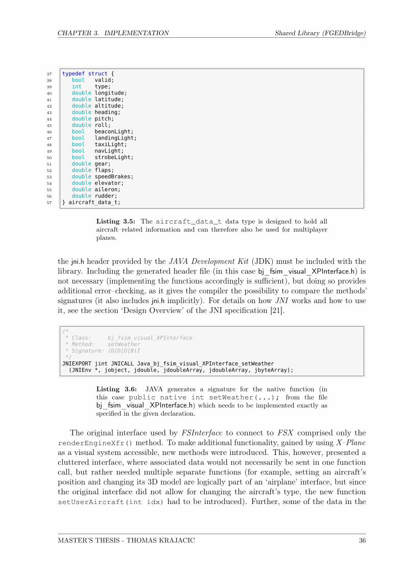
CHAPTER 3. IMPLEMENTATION Shared Library (FGEDBridge)
37 typedef struct {38 bool valid;39 int type;40 double longitude;41 double latitude;42 double altitude;43 double heading;44 double pitch;45 double roll;46 bool beaconLight;47 bool landingLight;48 bool taxiLight;49 bool navLight;50 bool strobeLight;51 double gear;52 double flaps;53 double speedBrakes;54 double elevator;55 double aileron;56 double rudder;57 } aircraft_data_t;
Listing 3.5: The aircraft_data_t data type is designed to hold allaircraft–related information and can therefore also be used for multiplayerplanes.
the jni.h header provided by the JAVA Development Kit (JDK) must be included with thelibrary. Including the generated header file (in this case bj_fsim_visual_XPInterface.h) isnot necessary (implementing the functions accordingly is sufficient), but doing so providesadditional error–checking, as it gives the compiler the possibility to compare the methods’signatures (it also includes jni.h implicitly). For details on how JNI works and how to useit, see the section ‘Design Overview’ of the JNI specification [21].
/** Class: bj_fsim_visual_XPInterface* Method: setWeather* Signature: (D[D[D[B)I*/
JNIEXPORT jint JNICALL Java_bj_fsim_visual_XPInterface_setWeather(JNIEnv *, jobject, jdouble, jdoubleArray, jdoubleArray, jbyteArray);
Listing 3.6: JAVA generates a signature for the native function (inthis case public native int setWeather(...); from the filebj_fsim_visual_XPInterface.h) which needs to be implemented exactly asspecified in the given declaration.
The original interface used by FSInterface to connect to FSX comprised only therenderEngineXfr() method. To make additional functionality, gained by using X–Planeas a visual system accessible, new methods were introduced. This, however, presented acluttered interface, where associated data would not necessarily be sent in one functioncall, but rather needed multiple separate functions (for example, setting an aircraft’sposition and changing its 3D model are logically part of an ‘airplane’ interface, but sincethe original interface did not allow for changing the aircraft’s type, the new functionsetUserAircraft(int idx) had to be introduced). Further, some of the data in the
MASTER’S THESIS - THOMAS KRAJACIC 36

CHAPTER 3. IMPLEMENTATION Shared Library (FGEDBridge)
original interface is required at a higher frequency (e.g. ‘aircraft position’ and ‘attitude’),but it seems useless to send data like ‘date’ or ‘weather’ 200 times per second, as theseparameters are slowly changing at best. For these reasons, a new interface was constructedand the original one was considered a ‘legacy interface’, but could still be used. Table 3.2lists the methods that the FGEDBridge library provides via JNI. The legacy interface iscolored in red, the newly introduced interface in green and yellow, the latter containingthe functions needed to augment the legacy interface in order to provide full functionality.The calling JAVA application was renamed to XPInterface, to clearly indicate that thenew interface is being used.
Return Type Name Notes
byte renderEngineXfr(...) Legacy interface. This is the only method previously available.For a list of parameters see table 3.1 on page 27.
int setUserAircraft(...) This function can be used in combination with the legacymethod renderEngineXfr(...). It is used to change theprimary aircraft type which is useful mostly if an externalview of the simulation is displayed (see section 3.4.3).
int calibrateView(...) Used to set up the initial alignment of the projectors (seesection 3.4.5). Not needed during simulation.
int setCamera(...) Function to control the camera for an external view of theaircraft. See section 3.4.5 for more information.
int setWeather(...) This function sends all weather–related data to the simulator.See section 3.4.6 on how this is implemented.
int setDateTime(...) Function for sending date and time, so X–Plane displays theenvironment appropriately (see section 3.4.7).
int setAircraft(...) This newly introduced method provides a clean interface to setall aircraft–related data for the main as well as all multiplayeraircraft. See section 3.4.3 on details on its implementation.Note that using this method would be required by the oldinterface to control multiplayer aircraft.
int getReturnValues(...) This function allows XPInterface to retrieve framerateand ground elevation provided by X–Plane. In theoriginal interface a double array was passed to therenderEngineXfr(...) method, so for the new interfaceto be compatible, it was implemented in the same manner.See section 3.4.8 for more information on how variables arepassed back using JNI.
String[] getAircraftModels() This function returns an array of path names for all aircraftmodels defined for the X–Plane plugin. It can be used, forexample, to display a popup–list in JAVA, where an aircrafttype can be chosen (instead of just using integer indices). Seesection 3.4.4 for more information on custom 3D aircraft mod-els.
int setPilotsHead(...) This method can be used to calibrate the display to theposition of the pilot’s head (see section 3.4.5).
Table 3.2: The JNI interface provided by the FGEDBridge library. The legacyinterface is marked red, the new interface green, and methods included in bothinterfaces are colored yellow. The new interface provides a much cleaner way ofinteracting with the simulator and its use is therefore recommended.
MASTER’S THESIS - THOMAS KRAJACIC 37

CHAPTER 3. IMPLEMENTATION Shared Library (FGEDBridge)
For a comprehensive look at the parameters of the individual functions see the User’sGuide on page 67 or have a look at the source code of FGEDBridge.cpp.
3.3.3 C/C++ Interface
After the X–Plane plugin FGEDCommander has loaded the FGEDBridge library it usesthe C/C++ interface. The library needs to provide a complete set of functions for theplugin so that all necessary data can be exchanged with the FGED simulator. Since thedata has been conveniently structured (see section 3.3.1) only few methods are needed(see listing 3.7)
85 extern "C" {86 MY_EXPORT int setReturnValues(double fr, double elev);87 MY_EXPORT int setAcModelPaths(char paths[128][512]);88 MY_EXPORT aircraft_data_t * getAircraftData();89 MY_EXPORT weather_data_t * getWeatherData();90 MY_EXPORT datetime_data_t * getDateTimeData();91 MY_EXPORT control_data_t * getControlData();92 MY_EXPORT int * getStatus();93 }
Listing 3.7: The C/C++ interface provided by the FGEDBridge library.
The directive extern "C" is used to specify C linkage convention, so linking to thelibrary does not become compiler–dependent (see Stroustrup [27, Chapter 9]).
For the FGEDCommander plugin to send data to the FGED simulator, the FGEDBridgelibrary provides the functions setReturnValues(...) and setAcModelPaths(...).Further, the function getStatus() is useful for checking whether initialization of thelibrary was successful (see section 3.3.1) and the three functions getAircraftData(),getWeatherData() and getDateTimeData() are used to retrieve data about aircraftand weather, as well as the date and time. Finally, getControlData() can be utilized toretrieve data needed to control various aspects of the simulation. The latter four methodsreturn pointers to the local cache the library holds for the appropriate data in sharedmemory (see Listing 3.4 on page 34). It is important to note that no other process canaccess this local cache and therefore it can be read without the risk of it being altered at thesame time (this holds true, since no other threads are spawned by the FGEDCommanderplugin which could access this data, and the plugin’s code is executed sequentially withoutexception).
The FGEDBridge library also defines the maximum aircraft count it can handle. Byincluding its header file FGEDBridge.h this number is available to every program linkingagainst the library at compile–time (see listing 3.8).
MASTER’S THESIS - THOMAS KRAJACIC 38

CHAPTER 3. IMPLEMENTATION X–Plane Plugin (FGEDCommander)
20 #define MP_COUNT 9
Listing 3.8: The maximum number of multiplayer aircraft the FGEDBridgelibrary can handle is defined in its header file. This header is also included bythe FGEDCommander plugin, so it knows not to try to control more aircraftthan the library supports.
3.4 X–Plane Plugin (FGEDCommander)
The second part of the FGED–link solution is implemented as a plugin for X–Plane. Thisplugin loads the FGEDBridge library and has thereby access to the data sent by the FGEDsimulator. In principle, an X–Plane plugin is, just like FGEDBridge, a shared library. It isloaded by X–Plane and can thus add functionality to it. The features a plugin can provideare limited only by the constraints the X–Plane SDK interface imposes. The tasks theFGEDCommander plugin has to manage are:
• Read input values, convert them as necessary, and set the corresponding X–Planeparameters so it can act accordingly.• Get frame rate and ground elevation at the aircraft’s position and send it back to
the FGED simulator.• Allow for a multi–screen setup where the viewing angles for the left and right
projector can be configured.• Implement a possibility to present an external view of the aircraft on an additional
PC.• Provide a simple way to add aircraft models to all X–Plane instances.• Make it possible to calibrate the pilot’s position for simulating a precision approach.
The following sections will elaborate on how these features are implemented.
3.4.1 Anatomy of an X–Plane Plugin
An X–Plane plugin requires a basic structure that is defined by the SDK (see X–Plane SDK[32, Section Overview ]). This includes a number of callbacks that have to be implemented,or at least defined. They need not necessarily provide any functionality in every plugin.Listing 3.9 shows the minimalist implementation of an X–Plane plugin.
MASTER’S THESIS - THOMAS KRAJACIC 39

CHAPTER 3. IMPLEMENTATION X–Plane Plugin (FGEDCommander)
#include <string>
PLUGIN_API int XPluginStart(char *outName, char *outSig, char *outDesc) {strcpy(outName, "name");strcpy(outSig, "signature");strcpy(outDesc, "description");return 1;
}
PLUGIN_API int XPluginEnable(void) {return 1;
}
PLUGIN_API void XPluginReceiveMessage(XPLMPluginID FrWho, long Msg, void *Prm) {}
PLUGIN_API void XPluginDisable(void) {}
PLUGIN_API void XPluginStop(void) {}
Listing 3.9: A minimalist X–Plane plugin consists of five callbacks that mustbe implemented.
Additionally, processing– or drawing–callbacks can be registered to be used for calcula-tions or drawing during simulation. The basic lifecycle of an X–Plane plugin is shown infigure 3.8.
XPluginStart XPluginEnable XPluginDisable XPluginStop
XPluginReceiveMessageProcessingCallbacks
DrawingCallbacks
Mouse/KeyboardCallbacks
X-Plane simulator cycles
Figure 3.8: The typical lifecycle of an X–Plane plugin.
It is important to know that a plugin will be called and run inside X–Plane’s mainprocess and therefore must not block execution at any time. The quicker the code inside aplugin can be executed the faster the simulator can run, and the more frames per secondare possible. Based on experience with the FSX implementation the goal of achieving atleast 30 frames per second was set. See section 4.3 for information about the performanceof the developed solution.
Plugins would be permitted to spawn their own threads, which means that X–Planedoes not have to wait for every part of the plugin’s execution, but this approach introducesseveral difficulties attached to concurrent programming. Therefore the simpler path ofkeeping the execution time of the plugin to a minimum was chosen.
Figure 3.9 gives an overview of the structure of the final FGEDCommander plugin andshows the different callbacks used.
MASTER’S THESIS - THOMAS KRAJACIC 40

CHAPTER 3. IMPLEMENTATION X–Plane Plugin (FGEDCommander)
reads and sets aircraft parameterssends return values to FGEDBridge
FGEDDataExchangeCallback
stores original pilot coordinatesreadjusts camera position
LoadingFinishedCallback
activates main processing callbackssets initial view (and angles)
FGEDInitializerCallback
reads environment parametersadjusts pilot’s head position
FGEDEnvironmentUpdateCallback
checks for planes being loaded
XPluginReceiveMessage
positions external camerareads from control data
RepositionCamera(...)
unregisters callbacks and cleans up
XPluginStop
XPluginDisable
reads con�guration �lesends list of models to FGEDBridgeacquires control over multiplayer aircraft
XPluginEnable
registers all callbacksloads FGEDBridge library
XPluginStart
con�guration �le
# frequency the plugin updatesfrequency:40
# Viewing angles for this instance.view-h:0view-v:0
# Downloaded additional aircraftFGED/MD-10F FEDEX 1.0/MD10.acfFGED/DC10-30 Transaero/DC10.acfFGED/A321/A321.acfFGED/A332 RR/LX332.acf
User interface callbacks
displays information about multiplayer planes
FGEDMultiplayerWindowCallback
MyHandleKeyCallback
displays debugging information
FGEDDebugWindowCallback
delegates menu clicks
FGEDMenuHandlerCallback
allows to calibrate the view for multiple projectors using control data
FGEDAdjustViewWindowCallback
MyHandleMouseClickCallback
DisablePanelDrawingCallback
DisableGaugesDrawingCallback
Drawing phase overrides
FGEDBridge
ctrl_data
aircraft_data
env_data
return_data
Shar
ed M
emor
y
invocation
Callback initiatedby FGEDCommander
Callback
�le access
Helper function
Function()
FGEDBridgeaccess
Callback requiredby X-Plane
Callback
FGEDCommander
Figure 3.9: Structural overview of the FGEDCommander plugin.
As some of the data controlling X–Plane’s behavior does not change during runtime, aconfiguration file is used to provide support for per–computer settings that do not need
MASTER’S THESIS - THOMAS KRAJACIC 41

CHAPTER 3. IMPLEMENTATION X–Plane Plugin (FGEDCommander)
constant updating. This file also provides an easy way of telling the X–Plane instancewhich visual–machine it is running on (left, center or right) — an important informationneeded for displaying the correct view of the environment.
FGEDDataExchangeCallback and FGEDEnvironmentUpdateCallback perform mostof the core functionality of the plugin. The first one is called for every frame the simulatordraws, and causes the FGEDBridge library to update its cache from shared memory. Thenit provides pointers to control data to be used by all other callbacks while processingaircraft–related data itself. The second callback is called at a lower frequency and is usedmainly to update the time and weather in X–Plane. It is also used to update the positionof the pilot’s head (see section 3.4.5) since this feature also does not require a high updatefrequency.
While it is possible to specify the time between processing callbacks to be extremelyshort, their maximum call frequency is limited by the current frame rate the simulatorachieves. It is therefore paramount that the execution time of any code in the plugin iskept to the absolute minimum, otherwise this would directly slow down the simulator.
For more information on the individual callbacks, browse through the source code ofthe FGEDCommander plugin (FGEDCommander.cpp), which is extensively documented.
3.4.2 Setting and Getting X–Plane Parameters
To set and get X–Plane data like position, time or aircraft lighting, the X–Plane SDKprovides an extensive collection of data references (datarefs) — each corresponding toa specific function in X–Plane (see [31]). Using these datarefs, it is possible to read ormodify the data X–Plane is using. Depending on the data type, different functions need tobe called (see X–Plane SDK [32, section XPLMDataAccess ]). To spare oneself the troubleof using the incorrect function because the wrong data type is assumed, the FGEDHelpernamespace provides a C++ function template that unifies access to all different data types.To take advantage of this method, data must be stored with the same type that X–Planeuses. As a result, the compiler can automatically generate the appropriate functions for thespecified types and apply the correct variant to set and get data of the corresponding datatype (see Listing 3.10). This helps keeping the source code easier to read and maintain.
31 template <class T> void set(const T& param, const XPLMDataRef& ref);32 template <> void set<int>( const int&, const XPLMDataRef&);33 template <> void set<float>( const float&, const XPLMDataRef&);34 template <> void set<double>(const double&, const XPLMDataRef&);35 template <> void set<bool>( const bool&, const XPLMDataRef&);36
37 template <class T>38 void set_cached(const T& param, T& cache, const XPLMDataRef& ref);
Listing 3.10: A C++ template and appropriate specializations provide aunified interface to access data of different types.
MASTER’S THESIS - THOMAS KRAJACIC 42

CHAPTER 3. IMPLEMENTATION X–Plane Plugin (FGEDCommander)
Being able to silently convert from the boolean data type to an integer is anotherbenefit of this solution (see Listing 3.11), as X–Plane sometimes uses the latter when aboolean value would be more intuitive.
64 template <>65 inline void FGEDHelper::set<bool>(const bool& p, const XPLMDataRef& r) {66 XPLMSetDatai(r, p?1:0);67 }
Listing 3.11: The implementation for the boolean data type silently convertstrue and false into an integer, as required by X–Plane.
To further structure the source code, data and functions associated with an aircraftwere encapsulated in an Aircraft class, and thus any code about setting and getting relateddata was hidden from the main plugin implementation. The same was done for datapertaining to the environment, such as date, time or weather. These classes additionallyprovide a good place to hide X–Plane–specific conversions into non–SI units as needed10.
In the case of input data remaining constant for a long period of time (like the statusof aircraft lights or the day of the year) and it therefore being unnecessary to constantlytell X–Plane to set the same value over and over again, the use of classes proves to beadvantageous as well. As suggested by Bulka and Mayhew [4], the fields of these classescan be used as cache, and only after comparison with this cache fails, the values need tobe reset in X–Plane. This was also implemented in the function template to set and getX–Plane data (see Listing 3.12).
72 template <class T>73 inline void FGEDHelper::set_cached(const T& param, T& cached_param,74 const XPLMDataRef& ref) {75 if ((param != cached_param) || FGEDHelper::dirty) {76 FGEDHelper::set<T>(param, ref);77 memcpy(&cached_param, ¶m, sizeof(param));78 }79 }
Listing 3.12: The implementation of the set_cached(...) functiontemplate reveals the method of caching data that should be sent to X–Plane.Only if the values of the new data and the cache differ the data is sent to X–Plane.The global variable FGEDHelper::dirty can be used to manually overridethe use of the caching mechanism.
The only problem introduced by caching, though, is that of initial state. If the initialvalue of the cache by coincidence is the same as what was supposed to be sent to X–Planethe value would never be set, even if X–Plane’s state was different. The problem mainly10Mainly, X–Plane uses degrees to specify angles whereas the appropriate SI unit is radians (seehttp://www.bipm.org/en/si/). The FGED simulator consequently handles all data in SI units, andthey are stored as such in the FGEDBridge library’s shared memory. As a minor exception, only thedeflection angle for the projectors is handled in degrees.
MASTER’S THESIS - THOMAS KRAJACIC 43

CHAPTER 3. IMPLEMENTATION X–Plane Plugin (FGEDCommander)
concerns values that do not change frequently, describing a state, so to speak. If, forexample, the altitude of the plane needs to be set to 0m and the cache already containsthat value (being initialized to 0 for example), then the plane will not move, no matterwhere it actually is. This is not really a problem, as in usual simulation the altitude valuewill change within a fraction of a second, and thus create a ‘cache miss’, resulting in thecorrect setting of the value with X–Plane. If, however, the landing light is to be switchedoff (X–Plane might start with it switched on), the value 0 is sent to the plugin. TheAircraft class defaults to ‘false’, which is equivalent, and therefore the comparison willreveal that no action has to be taken, regardless of what X–Plane actually shows.
There are various solutions to solve this problem. Looking at the example with theaircraft’s altitude it becomes obvious that setting the default value for the altitude in theAircraft class to some impossible value (like −1000m) will always result in a ‘chache miss’and therefore solve the problem of initial state. It gets tricky, though, with boolean types.These only have two possible values, true and false. There is no way to set a differentvalue that does not occur during simulation. This could be solved by using an integer inits place, where a value of 0 indicates false and 1 indicates true. Initially setting it toany other value will then mismatch the cache (if only 0 or 1 are sent) and force an updatein X–Plane.
However, since the use of booleans seems more appropriate with regard to on/offparameters, a different approach was chosen. The FGEDHelper namespace provides aglobal ‘dirty’ flag, that, if set to true, will let a cache comparison fail in any case andtherefore every value will be sent to X–Plane. This method of circumventing the cachingmechanism only needed minor code changes which made it even more appealing.
The only thing left to consider is, when to activate and deactivate the ‘dirty’ flag. Theproblem with the cache preventing an update can actually only occur when a parameterhas never been changed from its initial value. The example with the landing light couldhave also been solved initially by just switching the light on and off once. The essentialrequirement is that the value X–Plane has currently set and the value of the correspondingfield in the Aircraft class (or any other class that uses caching in this manner, like theEnvironment class) must match. Circumventing the cache only once at the start ofX–Plane should consequently be sufficent, but it seems to make even more sense to juststart with the caching mechanism deactivated, and turning it on early in simulation.This is done by setting the ‘dirty’ flag to false after FGEDDataExchangeCallback andFGEDEnvironmentUpdateCallback have run at least once (see Listing 3.13).
666 // This ensures, that both major callbacks were run at least once.667 if (FGEDHelper::dirty && high_freq_cb_done && low_freq_cb_done) {668 FGEDHelper::dirty = false;669 }
Listing 3.13: The caching mechanism is deactivated during startup and thenactivated by setting the ‘dirty’ flag to false. high_freq_cb_done andlow_freq_cb_done are initially false but are set to true at the endof their respective callbacks.
MASTER’S THESIS - THOMAS KRAJACIC 44

CHAPTER 3. IMPLEMENTATION X–Plane Plugin (FGEDCommander)
3.4.3 Aircraft Control
Having dealt with the details of getting and setting data in X–Plane, telling X–Planewhere and how to display an aircraft is now straightforward using the Aircraft class (seeListing 3.14).
622 static int count = std::min(aircrcnt, MP_COUNT+1);623 for (int i = 0; i < count; i++) {624 Planes[i].enabled = ac_data[i].valid;625
626 if (Planes[i].enabled) {627 Planes[i].disable_counter = 0;628
629 Planes[i].setPosition(ac_data[i].latitude,630 ac_data[i].longitude,631 ac_data[i].altitude);632
633 Planes[i].setAttitude(ac_data[i].heading,634 ac_data[i].pitch,635 ac_data[i].roll);636
637 Planes[i].setLights( ac_data[i].beaconLight,638 ac_data[i].landingLight,639 ac_data[i].taxiLight,640 ac_data[i].navLight,641 ac_data[i].strobeLight);642
643 Planes[i].setFeatures(ac_data[i].gear,644 ac_data[i].flaps,645 ac_data[i].speedBrakes,646 ac_data[i].type);647 } else {648 Planes[i].disable_counter++;649 }650
651 // This hides aircraft that have not been recieving coordinates for652 // more than ’DISABLE_DECAY’ seconds.653 if (Planes[i].disable_counter == decay_cycles) {654 Planes[i].default_location();655 }656 }
Listing 3.14: Setting aircraft–related parameters is straightforward using theAircraft class. Since multiplayer planes can’t be hidden, they are placed faraway whenever considered ‘deactivated’ after a certain amount of time withoutreceiving parameters.
One more thing to consider is the fact that multiplayer aircraft cannot be hidden inX–Plane. As the number of multiplayer planes has to be set via X–Plane’s user interfaceand cannot be changed using the SDK it is necessary though, to set the number of planesto the maximum number that might be needed at any time. The obvious solution for thisis to simply put unsused aircraft far away out of sight. The Aircraft class puts them to−70◦ latitude, −30◦ longitude by default.
To avoid that the FGED simulator has to enable and disable multiplayer aircraftmanually (by using a separate method for activating and deactivating), the plugin checksif data is being sent for a particular plane. This way the FGEDCommander plugin knows
MASTER’S THESIS - THOMAS KRAJACIC 45

CHAPTER 3. IMPLEMENTATION X–Plane Plugin (FGEDCommander)
the aircraft is being used and positions it according to the sent parameters. Disabling aplane is achieved simply by not sending any new parameters, which results in the datathat is read from shared memory being flagged invalid (see section 3.3.1). This in turnlets the plugin know that the aircraft is no longer used and can be put back to the defaultlocation above the Antarctic sea.
A slight problem with this approach is that, in the unfavorable event of the X–Planeplugin reading shared memory faster than FGED can write to it (which could happen ifXPInterface’s update rate was manually reduced to decrease processor load, or simply ifthere is an intermittent network problem), the plugin would immediately move the planeout of sight. Even if X–Plane would move it back to the correct position, this would nothappen within a single frame, as the loading of aircraft into the scene takes its time. Toovercome this problem, a counter is introduced, counting the simulator cycles a plane hasnot received new data. If the counter reaches a predefined value, the plane can be safelyconsidered ‘disabled’.
3.4.4 Changing Aircraft Models
Figure 3.10: This model of a KC-10 is one of many aircraft, that comepre–installed with the X–Plane distribution. Many more are available onthe internet, since X–Plane has a worldwide community of users who createadditional content commercially or for free.
Besides setting the aircraft’s position, attitude, lighting, flap-, gear-, and speedbrakedeployment, it is also possible to choose the aircraft’s type. For that purpose, the
MASTER’S THESIS - THOMAS KRAJACIC 46

CHAPTER 3. IMPLEMENTATION X–Plane Plugin (FGEDCommander)
appropriate 3D models have to be installed for X–Plane to use them. X–Plane has aworldwide community of users creating many different kinds of additional content for thesimulator. This also includes aircraft models to use with the simulator. These modelshave to be copied to every computer they are intended to be used on. It was necessary toimplement some mechanism to allow for choosing different models through the FGED–linkinterface, which meant that a list of available models was required. Since all models couldeasily be copied to every X–Plane installation on all three visual–PCs the only problemwas to make sure that the list of models used by the plugin is the same on every machine.This was solved by defining a small set of default aircraft which are all included in theX–Plane distribution (see Listing 3.15) and could hence be precompiled into the plugin,and a second list of optional aircraft, which could be set up through a configuration file (seelisting 3.16). This clearly defines the list of available models and also allows for assigninga specific order among them with persistent indices in the list.
386 add_aircraft_path("General Aviation/Cirrus TheJet/C4.acf");387 add_aircraft_path("General Aviation/P180 Avanti Ferrari Team/avanti.acf");388 add_aircraft_path("General Aviation/StinsonL5/L5.acf");389 add_aircraft_path("General Aviation/Baron B58/Baron_58.acf");390 add_aircraft_path("General Aviation/Cessna 172SP/Cessna_172SP.acf");391 add_aircraft_path("General Aviation/KingAir C90B/KingAirC90B.acf");392 add_aircraft_path("Heavy Metal/KC-10/KC-10.acf");393 add_aircraft_path("Heavy Metal/B777-200 British Airways/Speed-Bird.acf");394 add_aircraft_path("Heavy Metal/B747-400 United/747-400 United.acf");
Listing 3.15: The Aircraft class sets up a few default models shipping withX–Plane. The add_aircraft_path(std::string) method can auto-matically convert the directory separator for the current platform.
# · · ·# Aircraft models to add to the listFGED/Gulfstream G250 good/Gulfstream G250.acf# · · ·
Listing 3.16: Plane models can be added using the config.txt file located nextto the FGEDCommander plugin.
By setting the type of an aircraft to an integer representing the position in thelist of aircraft models, it is possible to change the type of aircraft. The JNI methodgetAircraftModels() retrieves this list from shared memory so it can, for example, bedisplayed at the instructor’s station.
One little nuisance of X–Plane is that, whenever changing the 3D model of an aircraft,its altitude shifts slightly (there are some other oddities, like the view not being retained,but those are discussed later in this section). Therefore it was necessary to reset thealtitude immediately after changing the model, as the jumping of the plane was visible,even if it was just for one frame (as FGED is continuously setting the correct altitude). Ifthe aircraft was placed at a constant altitude, this is more of a problem though, since thecaching mechanism described in section 3.4.3 would not reset the aircraft to the receivedposition, as it assumed the model to be still at that constant altitude. The Aircaft class
MASTER’S THESIS - THOMAS KRAJACIC 47

CHAPTER 3. IMPLEMENTATION X–Plane Plugin (FGEDCommander)
takes care of this problem by immediately setting the local y coordinate (see 2.1.4) to thevalue received previously using the FGEDHelper::set method, which does not implementthe cache (see Listing 3.17)
238 XPLMSetAircraftModel(this->aircraft_number, Aircraft::acpaths[idx]);239 this->aircraft_type = idx;240 // Due to X-Plane inadvertently modifying the elevation when changing241 // the aircraft model, we are immediately resetting the height.242 FGEDHelper::set(this->y, dr_plane_y);
Listing 3.17: The Aircraft class resets the y–coordinate after changing the 3Dmodel. This is necessary since X–Plane inadvertently changes this value whenswitching plane models.
Unfortunately, this is not the only odd behavior when changing the 3D model of anaircraft. Switching the model for the primary plane, for example, results in the position ofit being set to the runway of the nearest airport. Additionally, if an external view wasdisplayed, it is reset to a cockpit view and, if a cockpit view was already displayed, thenthe Head–up Display (HUD) is redisplayed (if the aircraft has one) even if it was previouslydeactivated.
To deal with these problems, the LoadingFinishedCallback in the FGEDCommanderplugin checks if the view was external before loading the plane, and in this case resets it(see figure 3.11). It further disables the caching temporarily, so that all of FGED ’s valuesfor the plane are guaranteed to be in sync and the plane’s parameters, that it may initiallyhold, are overwritten.
FGEDDataExchangeCallback
Planes[i].setFeatures(..., type);
AircraftupdateAircraftModel(inType);
reset altitudereset position
primary plane multiplayer plane
XPLMSetUsersAircraft(...) XPLMSetAircraftModel(...)LoadingFinishedCallback
if view was externalreset to external view
FGEDHelper::dirty = true;
disable HUD again
This disables caching until the two main callbacks have run at least once and then re-activates it.
Figure 3.11: The LoadingFinishedCallback function is used to resetthe view if the model of an aircraft is changed. The Aircraft class already takescare of repositioning the aircraft. The FGEDDataExchangeCallbackkeeps record whether the view was external when the aircraft type had beenchanged.
MASTER’S THESIS - THOMAS KRAJACIC 48

CHAPTER 3. IMPLEMENTATION X–Plane Plugin (FGEDCommander)
3.4.5 View Configuration
Since the hardware of the visual system for the FGED simulator consists of three projectorspowered by three different machines (see figure 3.1 or 3.12) it is necessary to have threeinstances of X–Plane running, one on every computer. The difference between thoseinstances should only be the direction the pilot in X–Plane is looking at. This way theleft and right projectors’ images can be positioned precisely to blend in with the centralview and provide one visualization of the environment stretching all the way across theprojection wall. For this purpose, the FGEDCommander plugin allows for changing thehorizontal and vertical deflection angle of any cockpit view it displays.
projecti
on wall
CR L
Δh Δv
Figure 3.12: For the left and right projector to show an appropriate view, thehorizontal and vertical deflection angle can be specified in the configuration fileof the corresponding X–Plane instance.
Since the deflection angles do not change during simulation — they are related to theposition of the projectors and the projection wall — it seems appropriate to put theminto a configuration file instead of continuously sending them through the FGED–linkinterface. As the configuration file is presently only read once while the plugin loads (inthe XPluginEnable callback), a method to conveniently determine the correct angle isneeded.
The easiest way to line up the screens is certainly to simply adjust the angles whileviewing the entire scene. To do this, a view adjustment mode was introduced in theFGEDCommander plugin. When the View–Adjustment Window is open (Plugins >FGEDCommander > Toggle View–Adjustment Window), the plugin listens forthe h– and v–deflection angles that can be sent using the calibrateView JNI method.
MASTER’S THESIS - THOMAS KRAJACIC 49

CHAPTER 3. IMPLEMENTATION X–Plane Plugin (FGEDCommander)
The angles are displayed in the center of the screen and once the correct setup is found,they should be written manually into the config.txt file (see listing 3.18).
# · · ·# Viewing angles for this instance.view-h:0view-v:0# · · ·
Listing 3.18: The horizontal and vertical deflection angles for the view canbe set in the configuration file (config.txt). The values set for view-h andview-v are used for horizontal and for vertical deflection respectively.
Another requested feature (see section 1.4, feature 5©) is the ability to horizontallyshift the image, so the pilot sitting in the cockpit can see objects that are in front of theaircraft directly ahead, instead of in the center of the projection wall (see figure 3.13).This can become necessary when wanting to simulate a precision approach, where the pilotconcentrates on the center line of the runway.
Naturally, when sitting in a sizable real aircraft, the pilot is positioned relatively closeto the lateral center of the aircraft, which lets him view straight ahead and look alongthe runway’s centerline. In the FGED simulator, while having a life–sized cockpit andaircraft hull, the distance to the projection wall is relatively short (about 3.5m). Thismeans, when displaying the runway’s centerline in the center of the screen, the pilot willhave to look to the center, which in turn will not be the direction the center line is goingand thus feels unnatural. The angle ε is called parallax error as depicted in figure 3.13.
pilot co-pilot
ε/2ε/2
proj
ectio
n screen
Usually, distant objects that are directly in front of the aircraft are displayed in the center of the screen
pilot co-pilot
ε
display calibrated for pilot
image shifted to the left
Figure 3.13: To calibrate the projected image for the pilot, the image needs tobe shifted to the left. This can be achieved using the setPilotsHead(...)method.
To overcome this problem when using X–Plane, the FGEDCommander plugin canadjust the position of the pilot’s head in X–Plane (see figure 3.14). This, of course, means
MASTER’S THESIS - THOMAS KRAJACIC 50

CHAPTER 3. IMPLEMENTATION X–Plane Plugin (FGEDCommander)
that the parallax error of the person sitting in the co–pilot’s chair will get even worse,but that’s an acceptable trade–off for simulating such an approach. Only the use of acollimated display system could solve this problem (see section 1.2 about collimation).
The JNI method setPilotsHead(...) is used to calibrate the view for the pilot (orany other person’s position in the cockpit). It takes ∆x, ∆y, ∆z as arguments, whichshould contain the desired shift from a default position for the pilot’s head along theaircraft’s coordinate axes (see section 2.1.3) in meters. A positive ∆y will shift theprojected image along the negative Y –axis as seen in figure 3.14. The amount the imagemoves (∆y) for every meter the pilot’s head is shifted (∆y) depends on the scaling factorof the projection but the two values are in any case proportional.
+ y
y
pilot co-pilotpilot position
in X-Planey
+ y
X-Plane default X-Plane pilot centered calibrated for FGED
Figure 3.14: Calibrating the view is achieved by adjusting the position of thepilot’s head in X–Plane. Setting a positive ∆y will result in a shift of the image(∆y) along the aircraft’s negative Y –axis.
By default, X–Plane positions the camera where the 3D model of the aircraft currentlyused defines the pilot’s location. This is in any case unsuitable, since the pilot in thesimulator is not sitting on the center line of the display, as would be the case in frontof a common PC monitor, but already shifted to the left (the plane’s negative Y –axis)in the pilot’s seat of the simulators life–sized cockpit (see figure 3.14). Therefore, theFGEDCommander plugin sets the y–coordinate of the pilot’s position to 0, no matterwhat the 3D model defines.
External View
Finally, it might also be desirable to have a view of the aircraft from the outside. For thispurpose, X–Plane can be installed on an arbitrary PC connected to the simulator networkusing the FGED–link interface. Using the configuration file config.txt, the plugin can betold to display an external view (see Listing 3.19). By specifying view:external theplugin also starts listening for camera parameters that can be sent over the JNI interface.
MASTER’S THESIS - THOMAS KRAJACIC 51

CHAPTER 3. IMPLEMENTATION X–Plane Plugin (FGEDCommander)
# · · ·view:external# · · ·
Listing 3.19: The configuration file can be used to tell FGEDCommanderthat an external view of the aircraft should be displayed. This also activatescamera control over the JNI interface.
The JNI method setCamera(...) allows for setting the camera’s coordinates. Thecoordinate system for positioning the camera (Xb, Yb, Zb) is following the heading of theaircraft but ignoring its elevation and bank angles (Θ, Φ). This is equivalent to the NEDframe being rotated only by the yaw angle of the aircraft and seems to be the most naturalway to specify the coordinates for the camera (see figure 3.15). This way, rolling andpitching motion is better visible, which would not be the case if the camera stayed rigidlyattached to the aircraft’s coordinate system.
Ψ
Ψ
Θ
−Φ
center of mass
Yb
XbZb
Zb
Yb
Xb
XNED
YNED
ZNED
CXC
YC
ZC
Figure 3.15: The coordinate system for positioning the camera (C) is shownin green (Xb, Yb, Zb). It is following the heading of the aircraft but ignoring itselevation and bank angles (Θ, Φ).
The parameters for the JNI method setCamera(...) are therefore ∆x, ∆y, ∆z,measured against said reference frame, and ∆Ψ, ΘC , ΦC measured about the camera’sfixed axes (XC , YC , ZC). ∆Ψ is used instead of Ψ so that a value of 0 will not result inthe camera pointing north, but rather match the aircraft’s heading. The final parameterof setCamera(...) allows for changig the zoom factor of the camera.
MASTER’S THESIS - THOMAS KRAJACIC 52

CHAPTER 3. IMPLEMENTATION X–Plane Plugin (FGEDCommander)
If no camera parameters are transmitted to an X–Plane instance using ‘external view’mode because the setCamera() is never called, the camera is put at a default positionand points towards the aircraft’s center of mass. Once setCamera() has been called and,subsequently, no more parameters are received (ctrl_data will be flagged as invalid, seesection 3.3.1), the FGEDCommander plugin continues to update the camera’s heading tomaintain the last relative heading (∆Ψ) in relation to the aircraft, as well as the relativeposition to the aircraft. The other parameters are still being read from shared memory,and thus left unaltered.
3.4.6 Adjusting Weather
To provide the possibility to simulate different weather conditions, the FGED simulatorsends information about cloud types, cloud coverage and the lower and upper bounds ofthree cloud layers (see table 3.1 on page 27).
X–Plane’s cloud model consists of three cloud layers (layer 0, 1, and 2), numberedfrom the lowest layer in the atmosphere in ascending order. There are certain con-straints enforced by X–Plane, such as the minimum distance between layers being exactly2000ft (609.6m). Depending on the cloud type the thickness of the layers can be imposedwith further restrictions. Table 3.3 lists the different cloud types X–Plane supports, andtheir corresponding layer thickness. The ‘clear’ type is used to hide the cloud layer. Cirrusclouds are implemented with a fixed layer thickness. The thickness of a ‘cumulus’ or‘stratus’ layer can be controlled, but requires a value of at least 2000ft. X–Plane 10actually supports two kinds of cirrus clouds (‘thick’ and ‘thin’), but they are not yetaccessible through the SDK. Once they are, the index for the new type will be publishedand can be sent using setWeather(...) without any modifications to FGED–link.
Index Type/Name Layer thickness
0 clear 2000ft
? thin cirrus 2000ft
1 thick cirrus 2000ft
2 cumulus scattered ≥ 2000ft
3 cumulus broken ≥ 2000ft
4 cumulus overcast ≥ 2000ft
5 low stratus ≥ 2000ft
Table 3.3: Cloud layers contain restrictions concerning their thickness. The‘thin cirrus’ type was not yet implemented at the time of this writing in theSDK, so no index number can be given. Once it is accessible, the appropriateindex will be published in the SDK documentation.
MASTER’S THESIS - THOMAS KRAJACIC 53

CHAPTER 3. IMPLEMENTATION X–Plane Plugin (FGEDCommander)
There is a difference in the cloud models between FSX and X–Plane. X–Plane doesnot have a parameter for cloud coverage, but implements this feature rather throughdifferent cloud types. The FGEDCommander plugin defines an Environment class (seesection B.3.2) which encapsulates all cloud related data as well as the visibility and thedate and time. It takes the parameters FGED provides, from which it could createan adequate conversion to X–Plane’s weather system. However, it was decided not toconvert the meaning of parameters of the previous interface to the specific implementationX–Plane provides. Rather, appropriate values are sent already intended for X–Plane’s wayof describing clouds and table 3.4 lists the settings for X–Plane’s parameters to achieve adesired result based on the original interface.
Description ICAO Code X–Plane cloud type
Clear sky SKC Sky clear (0)Scattered SCT Cumulus scattered (2)Broken BKN Cumulus broken (3)Overcast OVC Cumulus overcast or low stratus (4 or 5)
Table 3.4: Conversion rules for X–Plane’s cloud system.
Presently, cloud coverage parameters sent by FGED are ignored, and only the alti-tude of cloud tops and bases, as well as the type index are sent to X–Plane using thesetWeather(...) JNI method. X–Plane will enforce the restrictions given in table 3.4in case they would be violated by input through FGED. This could result in layers beingshifted to higher altitudes in case they would not meet the minimum distance of 2000ftto the layer below, or layers’ thickness being altered to meet the restrictions.
The visibility parameter can be set in meters and has a maximum value of 100 statutemiles (160, 934.4m) and is at least 100m. X–Plane does not provide the existence of avisibility layer but, instead, the effect of reduced visibility is diminishing at increasingaltitudes until it is completely disabled. Unfortunately, this effect is quite unrealistic, as,looking down, the ground becomes more visible the further away one gets. According toan email received by Austin Meyer, the author of X–Plane, this might be changed in thefuture though.
An additional reason for the visibility setting being somewhat broken is the fact thatits effect is diminished when flying within a cloud layer, so that visibility suddenly becomesbetter rather than worse.
Other than that, the visibility setting was displayed quite accurately and to ensurethat the viewing distance value that X–Plane provides is matching real world conditions,the following test was conducted: A reference length was calculated from an airport mapand by positioning the plane in X–Plane and setting the maximum visibility to this exactdistance, it could be seen whether objects at the desired distance would still be visible.
MASTER’S THESIS - THOMAS KRAJACIC 54

CHAPTER 3. IMPLEMENTATION X–Plane Plugin (FGEDCommander)
The test indicates, that X–Plane’s visibility distance in viewing direction is matchingvery closely what could be seen in real life. Setting a visibility of 100m indeed makesobjects that are further away invisible. Unfortunately, the effect seems to be applied on aplane perpendicular to the viewing direction, so the effective visibility is slightly better inthe corners of the screen.
3.4.7 Setting Date and Time
Date and time can be set using the setDateTime(...) JNI method. Currently, theFGED simulator sends the simulated time of the day in seconds as an integer value. Thiscan be used to display the correct position of the sun and appropriate daylight conditions.The X–Plane SDK allows for setting the time of the day using a dataref, but requires afloat value.
It might seem acceptable to ignore time differences in the second–range and simply holdthe value constant until the next second, as the value is only used to display the correct timeof the day (and the lighting conditions do obviously not change that quickly). Unfortunately,X–Plane uses this time for the exact timing of strobe lights as well. Therefore, a floatingpoint value that is increasing at a constant rate is required, or any strobe light (or otherobject relying on the simulation time) might exhibit unintended behavior.
The solution implemented is rather simple and can be seen in listing 3.20. The time,as received from FGED, is set only if it differs from the time that X–Plane is currentlyreporting (X–Plane keeps increasing its internal time automatically). A difference of 5seconds is implemented as threshold, which should hardly ever be accumulated duringnormal operation, except during a change of the day (when the ‘second of day’ value jumpsback to 0), or when FGED would run in slow motion. Otherwise, setting the time to aspecific value will most likely result in a bigger time difference, and the plugin controlsX–Plane as intended.
51 void Environment::setDateTime(int day, float sec) {52
53 FGEDHelper::set_cached(day, this->dayOfYear, dr_dayOfYear);54
55 // We only update the time when we are off more than 5s. This means that56 // we will let the sim run on its own time since it is only used to57 // display the environment anyway. This is, because the beacon lights on58 // the aircraft depend on the sim’s continuously updated time, and we59 // only receive seconds as an integer.60 sim_time = XPLMGetDataf(dr_secOfDay);61 if (abs(sim_time - sec) >= 5.0) {62 FGEDHelper::set_cached(sec, this->secOfDay, dr_secOfDay);63 }64 this->secOfDay = sec;65 }
Listing 3.20: The Environment class provides a convenient method to set thedate and time in X–Plane. The time is only set if X–Plane’s value differs morethan 5 seconds.
MASTER’S THESIS - THOMAS KRAJACIC 55

CHAPTER 3. IMPLEMENTATION X–Plane Plugin (FGEDCommander)
3.4.8 Sending Return Values
While the primary task of the FGEDCommander plugin is to receive data from the FGEDsimulator, it also needs to send back information only X–Plane can provide. The mostimportant piece of information is the ground elevation, as only X–Plane has informationabout how the world outside the cockpit looks like. This is unknown to FGED, yet it isessential for positioning the aircraft on the runway, or calculating ground collision.
The FGED–link interface provides the getReturnValues(...) method to retrievean array of return values. Besides ground elevation, the frame rate X–Plane currentlyruns with is also returned. The implementation in FGEDBridge is seen in listing 3.21
382 JNIEXPORT jint JNICALL Java_bj_fsim_visual_XPInterface_getReturnValues383 (JNIEnv * env, jobject obj, jdoubleArray retValues) {384 // First get the pointer from JNI to where we need to write to.385 double * retVals = (double *)env->GetDoubleArrayElements(retValues, NULL);386
387 // We copy in the values from shared memory388 FGEDLinkMemory->lock();389 retVals[0] = sm_ret_data_ptr->framerate;390 retVals[1] = sm_ret_data_ptr->elevation;391 FGEDLinkMemory->unlock();392
393 env->ReleaseDoubleArrayElements(retValues, retVals, 0);394 return 0;395 }
Listing 3.21: The getReturnValues(...) JNI method writes groundelevation and frame rate back to XPInterface. No cache is required, since thevalues are written directly to the addresses the JNI environment specifies.
To be able to return multiple values in an array to the FGED flight simulator usingJNI (just as the previous interface using renderEngineXfr(...) did), it is necessaryto retrieve the memory addresses where the information is supposed to be stored first,and then write to them directly (see Oracle [21, ‘Get<PrimitiveType>ArrayElementsRoutines’]). Since the actual data is delivered, and not just a pointer returned, it is notnecessary to use the ‘local buffering’ introduced for the FGEDCommander plugin (seesection 3.3.1, ‘Synchronization and Caching’ on page 32). The JAVA array where thereturn values are supposed to be stored needs to be passed as parameter to the function.
For convenience, the FGEDCommander plugin also provides a list of available aircraftmodels (information only X–Plane/FGEDCommander can provide), which can be queriedusing the getAircraftModels() JNI method. This method returns an array of JAVAStrings containing the path names of all aircraft that can be used (the precompiled list inthe plugin and those added through the configuration file). This can be useful for choosingfrom a list of available aircraft in a user interface, as it also provides the information whichindex (used with setAircraft(); see section 3.4.4) relates to which 3D model.
MASTER’S THESIS - THOMAS KRAJACIC 56

Chapter 4
Conclusion
Working with X–Plane revealed that it is well suited for being used as a visual system.However, it became clear that flight simulation software intended for personal use andrunning on PC hardware has a different approach to realism than what a research simulatorrequires. While X–Plane provides incredible detail with regard to 3D aircraft modelsand scenery, other elements of the environment may look great but are not simulatedrealistically — most notably the behavior of the cloud system and the implementation ofvisibility. On the other hand, X–Plane provides a very realistic flight model but using itpurely as a visual system, this is not needed.
Software in general has the habit of never being finished. There are always featuresto add, code to refactor, or bugs to get rid of. FGED–link is no different. The followingchapter is intended to review the work done and give an outlook of how the solution canbe improved in the future. The section ‘Performance Analysis’ discusses performanceimplications by various aspects of the developed solution, as well as X–Plane and the usedhardware in general.
Figure 4.1: A screenshot of X–Plane 10 showing a detailed aircraft modeland scenery.
MASTER’S THESIS - THOMAS KRAJACIC 57

CHAPTER 4. CONCLUSION Feature Analysis
4.1 Feature Analysis
Looking at the finished product of this thesis, it is interesting to evaluate the features thatcould be integrated, or what functionality is left to be implemented in a future revision.Table 4.1 gives a concise overview of the previously defined goals (see section 1.4), whetherthey have been met, and what remains to be done.
# Feature Description
1© Integration withoriginal interface
The old JNI method renderEngineXfr(...) is imple-mented to work seamlessly with the FGED simulator. The onlyexception where care needs to be taken, is the different imple-mentation of clouds in X–Plane (see section 3.4.6 on page 53).To provide additional functionality which became available withX–Plane, new JNI methods were implemented to augment theold interface. Additionally, a completely new, more structuredinterface has been created, and its use is therefore strongly recom-mended (see table 3.2 on page 37).
2© Three–projector–setup Horizontal and vertical alignment is adjustable for each X–Planeinstance by using a configuration file (see section 3.4.5 on page 49).
3© Multiplayer aircraft Fully functional control of additional aircraft is implemented for usewith the setAircraft(...) JNI method (see section 3.4.3on page 45).
4© Improved lightsrendering
X–Plane’s graphics engine provides far better rendering of lightsthan the previously used engine. However, lights do not light upclouds, as these are not implemented as 3D objects.
5© Parallax compensation The view can be calibrated to eliminate parallax error for the pilotusing the setPilotsHead(...) JNI method.
6© Weather RADARsupport
Not implemented. The X–Plane SDK does not provide meansto control the weather in such a way to make this possible. Seesection 4.2, ‘Shortcomings of the Current Implementation’ forfurther information of how to solve this.
7© Controllable stop bars Proof–of–concept implemented in a separate plugin (see section 4.4,‘Possible Future Features’ for more information).
8© Airport lighting Lighting of runways and taxiways is very limited in X–Plane as it isimplemented not as realistic OpenGl lights, but rather colored dots,which are not completely accessible through the SDK. Activatingand deactivating, though, cannot be controlled but is automaticallyset by X–Plane according to weather conditions and time of theday. See section 4.2, ‘Shortcomings of the Current Implementation’for further information on how to possibly solve this.
Table 4.1: Feature analysis of the FGED–link solution.
MASTER’S THESIS - THOMAS KRAJACIC 58

CHAPTER 4. CONCLUSION Shortcomings of the Current Implementation
4.2 Shortcomings of the Current Implementation
Some features were not (or not fully) implemented — most notably the ‘weather RADAR’functionality. The problem is that the X–Plane SDK does not provide a way for fine–grained weather manipulation. It is not possible to tell X–Plane to put a cloud at positionX with a diameter of Y . It would at least be necessary to be able to specify thunderstormcells by position and magnitude to be able to draw an appropriate weather RADAR image.
One way to overcome this limitation of the X–Plane SDK is to draw the clouds oneself.This is possible since the SDK allows for hooking into X–Plane’s OpenGl drawing cycleand a plugin can thus draw arbitrary objects on the screen (see [32, Section Graphics]).The only downside of this method is that OpenGl programming knowledge is required.Furthermore, as the weather system in X–Plane 10 has been completely redesigned, itremains to be seen if the SDK will provide more convenient functions for this purpose inthe future.
A second feature not implemented is the ability to better control the lighting ofrunways and taxiways at airports. While the X–Plane SDK does in fact provide adataref ‘sim/graphics/scenery/airport_light_level’, this does not work as wouldbe required. X–Plane decides for itself when lights are switched on or off. Only when theyare switched on the light level can be controlled with this dataref. Additionally, the ‘lights’are not really lights, but rather just colored dots painted by the simulator and thereforedo not look very realistic (X–Plane 10 does provide realistic OpenGl lights interactingwith the surroundings and provide a high degree of realism, but those are not used forthis feature).
Concerning the desired feature that clouds are illuminated by an aircraft’s strobe orlanding lights, it is important to note that X–Plane’s clouds are not 3D objects, so theyare principally not affected by any light. It is not clear whether X–Plane will simulatethis behavior in the future, but for now it does not. It might be possible to draw asemi–transparent region in front of the plane that changes its brightness whenever anaircraft’s light would illuminate the cloud in front, but no method exists, to find outwhether a cloud is currently in front of the aircraft. Therefore it remains to be seenwhether Laminar Research will implement this feature or provide further interfaces tofacilitate a custom implementation. Additionally, the way visibility restriction is currentlyimplemented in X–Plane is severely lacking realism (see section 3.4.6). Austin Meyer, theauthor of X–Plane, stated in a reply to an email that this might be improved in the future.
Aside from the features that could not be fully implemented, there are some otherlimitations based on FGED–link ’s design:
There are hard–coded values for the number of multiplayer aircraft, the number of 3Dmodels that can be handled and other minor parameters, like the time delay after whichan aircraft is deemed disabled if no data is received from FGED (see section 3.4.3) or thesync threshold for the simulator’s internal time (see section 3.4.7).
While the two latter ones could be included as an option to be set in the config file,the others are fixed values by design. Allowing for an arbitrary amount of multiplayer
MASTER’S THESIS - THOMAS KRAJACIC 59

CHAPTER 4. CONCLUSION Performance Analysis
planes or 3D models would require some form of runtime memory allocation. Thiscomplicates the design, makes it more error prone (due to memory management andcorrect deallocating then being a responsibility of the programmer) and lastly could slowdown the plugin, as allocating heap memory takes more time than allocating memory onthe stack (see Stroustrup [27]).
Lastly, the interface for camera control is relatively limited. Ideally, it would be possibleto choose the reference coordinate frame for camera movement. This is something thatcould be considered in a future implementation if needed.
It should be noted that, even though the code of the FGED–link project is wellstructured, further refactoring could improve its design even more.
4.3 Performance Analysis
Whenever software runs in a time critical context, it is interesting to know how betterperformance can be gained or where crucial time is lost. Ideally, the visual systemimplemented would render enough frames per second, so that even the fastest motion onthe projection screen would appear to be fluid. However, aside from hardware limitations,there are several other factors within the components of the entire solution preventing this(see figure 4.2).
XPInterface FGEDBridge FGEDCommander X-Plane
Network
Figure 4.2: The entire solution consists of multiple components, each of whichhas an influence on how fast data is transmitted to the next one.
The Timer class (Timer.cpp) in FGEDBridge was specifically created for the purposeof objectively measuring performance by means of execution times. To record frameratesin a uniform way, the Time Demo script1 was used.
To observe approximate processor load, the Performance Monitor utility providedby Windows 7 was used . While reading those values is not highly accurate, it can beconsidered sufficient for this purpose.
The current three visual–machines are identical and have the following specifications:
While the specifications given in Table 4.2 are even below the minimum systemrequirements for X–Plane 10, they will suffice as intermediate solution until new hardwarecan be purchased. Luckily, X–Plane’s graphics engine can be tuned in many ways, so thateven low–end hardware can run it.1See http://wiki.x-plane.com/Timedemo_and_Framerate_Test
MASTER’S THESIS - THOMAS KRAJACIC 60

CHAPTER 4. CONCLUSION Performance Analysis
Processor Intel c© Core 2 Duo @ 2.53GHz
RAM 2GB
System Windows 7, 32–bit
Graphics card GeForce 8800GT (256MB)PCIe 16x
Table 4.2: The technical specifications of the three identical visual–PCs.
4.3.1 XPInterface
The first relevant factor for performance is the JAVA application XPInterface itself. Itwrites the data that FGED sends over the network to the shared memory provided byFGEDBridge using various JNI methods. This, inherently, requires a certain amountof the processor’s available power. Depending on how often the data is read from thenetwork and written to shared memory, the processor load imposed by XPInterface willvary. Surprisingly, the tests indicate that there is hardly any burden on the processor.Even at an update frequency of 200Hz processor load never rose significantly.
4.3.2 X–Plane
As a second step in testing the capacities of the entire solution it seemed useful to testX–Plane’s performance on its own (all plugins disabled, including FGEDCommander). Asstated in various blog entries on the Developer Blog (see Supnik [28]), X–Plane’s framerateis limited by different hardware factors and hardly any of today’s available PCs is capableof running X–Plane at very high framerates (> 100fps) in every situation with all settingsset at their maximum. To initially avoid influence by X–Plane’s graphics parametersthe test was conducted with all settings at their minimum. Since the frame rate heavilydepends on the current scenery that needs to be drawn, an automated fly–over was usedduring the tests, which allowed for observing average fps.
Figure 4.3 shows how different rendering settings influence the framerate on the visual–PCs. The CPU will be the limiting factor, as it was at 98% processor load even at thelowest settings possible in X–Plane.
Nevertheless, different graphics settings were tested. Fortunately, some of them aremostly dependent on the graphics card, and hence they are not actually influenced by thelack of processing power. For information on how to systematically enable more featuresin the graphics engine of X–Plane, see section A.2.3 in the User’s Guide.
MASTER’S THESIS - THOMAS KRAJACIC 61

CHAPTER 4. CONCLUSION Performance Analysis
0
10
20
30
40
50
60
minimum settings medium settings maximum settings
aver
age
fram
es p
er s
econ
d
Figure 4.3: Performance in frames per second (fps) on a visual–PC. Differenttests have been conducted to see the influence of various graphics settings inX–Plane. Processor load was at 98% even while flying at the minimum renderingsettings, which indicates that the CPU is the limiting factor for performance.
4.3.3 FGED–link
FGEDCommander and FGEDBridge are the components where performance can beinfluenced primarily. A lot depends on the design choices made during development andon the techniques used to implement certain features. The first concern is that the lockingof shared memory forces another process, while trying to access it, to wait until the lock isremoved and accesss granted. Looking at the frequencies at which locking happens fromboth sides (XPInterface and FGEDCommander are both accessing the shared memoryand can be considered ‘opposite’), and including the times the memory is actually locked,it becomes clear, that this does not pose any significant performance risk (see figure 4.4).
Suppose X–Plane runs at 50fps (a frame duration of 20 milliseconds), and XPInterfacesends data at 200Hz (this yields a time between those calls of 5ms). This means that,within every frame drawn by X–Plane, memory–locking, and thereby possibly thread–blocking, will occur:
• 4 times on average by XPInterface
• 3 times by FGEDDataExchangeCallback
(setReturnValues(), getAircraftData() and getCtrlData())
• Every 10th frame an additional 2 times by FGEDEnvironmentUpdateCallback
(getWeatherData(), getDateTimeData()) as this callback is preset to only runevery 0.2 seconds.
This means that, in the worst case, the memory is locked 9 times during a single frame.While it may sound a lot, only by looking at the times how long it is locked can thesituation be evaluated. Table 4.3 lists the recorded average execution times for all lockingfunctions. It can be seen immediately, that locking memory and accessing it is extremelyfast.
MASTER’S THESIS - THOMAS KRAJACIC 62

CHAPTER 4. CONCLUSION Performance Analysis
Caller Function Exec. time
FSInterface renderEngineXfr() 13µs
FGEDCommander setReturnValues() 1µs
FGEDCommander getAircraftData() 5µs
FGEDCommander getCtrlData() 1µs
FGEDCommander getWeatherData() 4µs
FGEDCommander getDateTimeData() 1µs
Table 4.3: The approximate average execution times of some critical functionslocking the shared memory.
Furthermore, the execution time of the plugin in general is relevant, as it directlyinfluences the speed at which X–Plane can run (see X–Plane SDK [32, Section Processing ]).There are two main callbacks in the FGEDCommander plugin that are run regularly.FGEDDataExchangeCallback is run for every frame, and, for data that does not needupdating every frame, FGEDEnvironmentUpdateCallback is run approximately every0.2 seconds (it will be called at the next frame, after 0.2 seconds have passed from itsprevious run).
Function Exec. time
FGEDDataExchangeCallback() 25µs
FGEDEnvironmentUpdateCallback() 12µs
Table 4.4: The approximate average execution times of the two main callbacksin the FGEDCommander plugin.
To get a picture of the proportionality between locking times and execution times ingeneral see figure 4.4. As the locking and execution times are so incredibly short comparedto the duration of one frame, their width is magnified separately 100 times. The exactposition of the functions in the image is unknown, as it is not revealed, when exactly theSDK calls the callbacks.
A last test was conducted to see how much influence the framerate, or rather the lackof processing power, has on the execution time of the callbacks and important functions inthe plugin.
It clearly shows (see figure 4.5) that most of the functions are not taking any longerto execute when X–Plane is running slower due to a lack of CPU power. Only the maincallback’s execution time increases slightly, which is probably based on it containing a lot
MASTER’S THESIS - THOMAS KRAJACIC 63

CHAPTER 4. CONCLUSION Performance Analysis
20ms = 150mm1μsec = 0.0075mm
renderEngineXfr() renderEngineXfr() renderEngineXfr() renderEngineXfr()
FGEDDataExchangeCallback()
FGEDEnvironmentUpdateCallback()
100x magni�cation
12 μs
FGEDEnvironmentUpdateCallback()
getWeatherData()getDateTimeData()
FGEDDataExchangeCallback()
setReturnValues()getCtrlData()
getAircraftData()
25 μs
1 frame = 20ms
Figure 4.4: Execution times in one simulator cycle put into perspective. Thewidth of the marks for function calls in the timeline indicates the actual durationof those calls. The position is not known as the SDK does not provide furtherinformation as to when the callbacks are called during X–Plane’s cycles.
0
5
10
15
20
25
30
35
40
50fps 40fps 9fps
exec
utio
n tim
e in
mic
rose
cond
s FGEDDataExchangeCallback
FGEDEnvironmentUpdateCallback
getAircraftData
getControlData
getWeatherData
getDateTimeData
Figure 4.5: The average execution times of several functions under increasingCPU stress. While this results in a considerable decrease in fps (as shown inthe chart), most of FGEDCommander ’s functions are resilient against it due totheir compact nature.
more instructions than the other functions. It will therefore be more often interrupted asthe processor divides up its time between multiple tasks.
While the introduction of the Aircraft class beautifully hides the extensive code neededto set and get X–Plane data, it also takes its toll in the form of execution time, as a lotmore function calls are introduced. Furthermore, the use of a cache for rarely changedinput values supposedly reduces processor load by not calling X–Plane quite so often
MASTER’S THESIS - THOMAS KRAJACIC 64

CHAPTER 4. CONCLUSION Possible Future Features
but, unfortunately, also takes longer to execute than to just set the value every cycle.Fortunately, the execution times within the FGEDCommander plugin are so short thatthis can be neglected (see figure 4.4).
4.4 Possible Future Features
Considering the already implemented features, there are still possibilities to enhance thesolution. Aside from improving the existing features, the X–Plane SDK allows for addingmany aspects of simulation not yet included within FGED–link. The following list is ashort collection of ideas that could be translated into new projects around FGED–link.
• To further enhance the exterior view of the aircraft, aside from the already im-plemented gear, flaps and speed–brakes, other moving parts could be correctlyanimated. Aileron, elevator and rudder parameters have already been included inthe setAircraft(...) function, but their input values are not yet utilized.
• As the FGED simulator can already simulate various aircraft failures, it would bea nice touch to draw appropriate effects for these (like smoke, for example) usingOpenGl.
• In an external view, it would be possible to visualize force, acceleration or otherparameters by drawing vectors next to the aircraft.
• While it has been shown that plugin–controlled stop bars on taxiways can beimplemented, integrating this solution and managing the stop bars is a challenge fora future venture.
• X–Plane’s airport lighting is lacking realism by not being implemented as realisticlights, but rather as colored dots. To possibly overcome this limitation it might befeasible to place custom–built light beacons along the runway using the World Editorapplication that is provided with the SDK for editing scenery. These objects couldthen be controlled via custom datarefs.
• As mentioned before, it is not possible to set or retrieve weather data in a way toconstruct a weather RADAR image. Creating METAR (see [10, Table A3-2 ]) filesand letting X–Plane use those would be a possibility, but the detail of this data isvery low in resolution.
As the SDK allows for drawing arbitrary objects, it would be possible to manuallyconstruct thunderstorm clouds, which in turn would allow for creating a simulatedweather RADAR image.
MASTER’S THESIS - THOMAS KRAJACIC 65

Appendix

Appendix A
User’s Guide
This chapter guides the user through the complete setup of a visual–PC controlling eitherone of the three main projectors or displaying an exterior view of the aircraft. Further, areference of the available JNI methods used to control X–Plane is given.
A.1 FGED–link Installation
The complete installation comprises the following components:
• The QtCore library
• The FGEDBridge library
• The X–Plane 10 installation
• The FGEDCommander plugin
• The Visual C++ Runtime
The QtCore library is part of the Qt libraries and can be obtained in various ways1.Usually it comes as part of an extensive installation package (either the ‘Qt SDK’, orthe ‘Qt libraries only’ package) that includes a lot more than needed in this case. Theeasiest way to provide a lightweight installation on the visual–PCs is to install the SDKon the development–machine and just copy the QtCore4.dll library that will be part of thatinstallation to the visual–machines. This can be done by using either the SDK installer orcompiling it from the source code which can be downloaded (for more information, seesection B.2.1 in the Developer’s Guide). It is important that the version of the QtCorelibrary on all visual–machines matches the one used in development. The DLL needs tobe copied to C:\Windows\System32\ on the visual–PCs.1See http://qt-project.org/downloads
MASTER’S THESIS - THOMAS KRAJACIC 67

APPENDIX A. USER’S GUIDE FGED–link Installation
FGED–link was initially developed with version 4.7.3 of the Qt SDK, but it should beeasily recompiled using a later version of the SDK.
The FGEDBridge.dll file should be copied to the C:\fged\bin\ directory, where theXPInterface.jar file resides.
X–Plane can be installed under C:\X-Plane 10\ or any other convenient location.It is important to know that the version shipping on DVD is most likely not the latestrelease, and thus an updated installer shoud be downloaded immediately. The latestunified installer and updater application can be found on the X–Plane website2. On futureDVD prints, this updater may already be included, but for now, this way of installingX–Plane is recommended.
The FGEDCommander plugin directory needs to be put into the Resources/plugins/subdirectory of the X–Plane installation. The plugin itself is called win.xpl and should be,along with the configuration file config.txt, in a folder called FGEDCommander within theplugin directory. When adding additional 3D aircraft models, it is suggested to put themin the X–Plane installation directory under Aircraft/FGED/.
Finally, to be able to run programs that have been developed with Microsoft VisualC++, it is necessary to install the appropriate runtime libraries on machines where they aredeployed. An installer can be downloaded from Microsoft ’s website3, but it is important touse the appropriate version that matches the one of Visual Studio used for development.
The install location of all necessary files (except for the Visual C++ runtime, whichthe installer automatically moves to the appropriate directory) is shown in figure A.1.
C:\fged
bin
WindowsSystem32
FGEDBridge.dll
QtCore4.dll
X-Plane 10Resources
pluginsFGEDCommander
win.xplconfig.txt
AircraftFGED
Figure A.1: The locations of all files to be moved into place for a completeinstallation. The FGED directory is optional and can be used to containadditional aircraft models intended to be used with X–Plane.
2See http://www.x-plane.com/downloads/x-plane_10_update/3See http://www.microsoft.com/download/en/details.aspx?id=5555
MASTER’S THESIS - THOMAS KRAJACIC 68

APPENDIX A. USER’S GUIDE X–Plane Setup
While not being part of the ‘installation procedure’, it is very important to updatenot just X–Plane regularly, but also the graphics card drivers. This has proven to boostperformance considerably in the past according to user reports on an X–Plane communityforum4.
A.2 X–Plane Setup
After having installed the required components of FGED–link, a few steps are necessaryto set up the visual–PCs for operation. These can be categorized into the following tasks:
• Adapting the configuration file for the respective visual–PC.
• Adjusting various settings in X–Plane that cannot be set automatically by theFGEDCommander plugin.
• Adjusting graphics settings in X–Plane for optimal performance.
A.2.1 The Configuration File
The configuration file config.txt resides in the FGEDCommander directory next to theX–Plane plugin (win.xpl). It can contain various directives to modify the behavior ofthe FGEDCommander plugin.
In general, each directive in the plugin is a name:value pair separated by a colon (:),except for lines ending in ‘.acf’. These are interpreted as aircraft model paths.
External View
Using the ‘view’ directive, the plugin can be told to display either a cockpit view oran external view (view:external) of the aircraft. Specifying an external view alsoactivates listening for camera parameters in the plugin (see section A.3.5). Setting ‘view’to anything other than ‘external’ or omitting it results in a cockpit view being displayed.
Projector Position
If the ‘view’ directive specifies a cockpit view, the two commands view-h:n and view-v:ntell the plugin the exact viewing angle for the pilot. This is used to display the appropriateimage on the left and right projectors. n needs to be a floating point (or integer) numberwith a dot (.) as decimal separator. The unit is degrees.4http://forums.x-plane.org/
MASTER’S THESIS - THOMAS KRAJACIC 69

APPENDIX A. USER’S GUIDE X–Plane Setup
Update Frequency
With the ‘frequency’ directive it is possible to control at which frequency the plugintries to update data. It shall be noticed, though, that the update frequency will neverexceed the frame rate X–Plane is currently running at. This setting was therefore mainlyuseful for testing purposes as the plugin did not have to be recompiled for changing theupdate frequency. If this directive is not specified, the plugin will default to calling themain callback every simulator cycle, which is equivalent to ‘every frame’ and delivers thebest result.
Adding Custom Aircraft Models
By default, the FGEDCommander plugin has a list of five plane models compiled in,shipping with the default X–Plane installation. To use additional models, they need to bespecified in the config.txt file by their path. An aircraft model directive is identified by theline ending in ‘.acf’. The path can be either relative from the Aircraft directory or absolutestarting with a ‘/’ (Mac/Linux) or ‘C:\’ (Windows). It does not matter whether slash–or backslash–notation is used, as the directory separator will be replaced for the currentplatform automatically. Only the ‘C:\’ needs to retain the backslash, but the drive letterneed not be ‘C’.
Platform Example
Windows, absolute C:\fged\bin\plane.acf
Mac or Linux, absolute /fged/bin/plane.acf
Crossplatform, relative FGED/DC10-30 Lufthansa vintage/DC10.acf
Table A.1: Different ways of adding aircraft models in the config.txt file.These paths need to be written into the configuration file of every visual–PC.
A.2.2 X–Plane Settings
Finally, it is necessary to adjust some settings in the X–Plane user interface, as it is notpossible to set them automatically using the X–Plane SDK.
Number of Aircraft
To be able to use additional aircraft, they need to be activated in X–Plane under Aircraft> Aircraft & Situations. Note that the number entered includes the user’s aircraft. Asetting of ‘10’ will result in 9 multiplayer aircraft being usable by the plugin. It is necessary
MASTER’S THESIS - THOMAS KRAJACIC 70

APPENDIX A. USER’S GUIDE X–Plane Setup
to restart X–Plane after changing the number of aircraft, because the FGEDCommanderplugin does not check if the aircraft count changes during runtime. This could beimplemented, but would make the plugin a lot more complex, and as the desired number ofmultiplayer aircraft does not change very often, it was considered an acceptable trade–off.
Figure A.2: Setting the number of aircraft in X–Plane using Aircraft >Aircraft & Situations. A restart of X–Plane is required after changing thenumber, as the FGEDCommander plugin does not adjust to this number duringruntime.
It does not matter which aircraft models are chosen in this dialog box becausethe FGEDCommander plugin will pre–fill the slots from its own list of models (hard–coded paths plus those added through the configuration file). This happens when theFGEDCommander plugin is loaded. Make sure the number of multiplayer aircraft is nothigher than what the library is compiled for (MP_COUNT), as excess planes will not becontrolled by the plugin and thus will fly around using X–Plane’s autopilot.
Viewing Options
Some of X–Plane’s default settings concerning the view are not suitable when using itas visual system. It is necessary to turn off the view indicator and dimming under highG–load under Settings > Rendering Options.
Figure A.3: Some options under Settings > Rendering Options are bestswitched off.
MASTER’S THESIS - THOMAS KRAJACIC 71

APPENDIX A. USER’S GUIDE X–Plane Setup
Furthermore, it is convenient to have X–Plane start in full–screen view, which can also beset in this dialog box.
Figure A.4: X–Plane can go into full–screen view immediately after starting.This is ideal when using it as visual system.
Most of the other options in this dialog box concern the visual quality of the environment.Ideally, all of them would be set to their highest value, but since the hardware will notbe fast enough for that, a balance needs to be found between visual quality and speed.Section A.2.3 will give information on how to proceed to find the optimal settings.
Sound and Warnings Settings
As X–Plane is only used to display the environment, the sound output should be switchedoff completely. This can be done under Settings > Sound.
Figure A.5: Disabling sound in X–Plane using Settings > Sound.
Additionally, in–cockpit text warnings that would appear on screen need to be turnedoff under Settings > Operations & Warnings. The low frame–rate warning can alsobe deactivated.
MASTER’S THESIS - THOMAS KRAJACIC 72

APPENDIX A. USER’S GUIDE X–Plane Setup
Figure A.6: The Settings > Operations & Warnings dialog providesoptions like disabling warnings in X–Plane.
A.2.3 Performance Tuning
Finding the right graphics settings in X–Plane is no easy task, as there are an abundanceof settings for different aspects of the visual quality, and they all influence performance ina different way. Ben Supnik, the co–author of the X–Plane SDK and also on the X–Planedevelopment team at Laminar Research, and Chris Serio, another developer at LaminarResearch, have written a few excellent articles on the Developer Blog (see Supnik [28]) onhow to tune X–Plane’s graphics settings for better performance. It is highly recommendedto read through these articles, as it seems not practical to just repeat that website’scontents here.
MASTER’S THESIS - THOMAS KRAJACIC 73

APPENDIX A. USER’S GUIDE JNI Interface Reference
To Tune Framerate, You Have To Hit Rock Bottomhttp://developer.x-plane.com/2010/01/to-tune-framerate-you-have-to-hit-rock-bottom/
X-Plane 10 and GPU Powerhttp://developer.x-plane.com/2011/10/x-plane-10-and-gpu-power/
X-Plane, SLI and CrossFirehttp://developer.x-plane.com/2011/10/x-plane-sli-and-crossfire/
What’s This Whole PCIe Thing About, Anyway?http://developer.x-plane.com/2011/10/whats-this-whole-pcie-thing-about-anyway/
A Few Settings Tricks to Tryhttp://developer.x-plane.com/2011/11/a-few-settings-tricks-to-try/
Rendering Settings and FPS: Don’t Panichttp://developer.x-plane.com/2011/11/rendering-settings-and-fps-dont-panic/
Tips for better frame rates Pt #1http://developer.x-plane.com/2011/12/tips-for-better-frame-rates-pt-1/
Mobile GPUs and Fill Ratehttp://developer.x-plane.com/2012/01/mobile-gpus-and-fill-rate/
Table A.2: A list of selected blog articles by Ben Supnik and Chris Serio abouttuning X–Plane’s rendering settings for better performance. Articles are listedin chronological order from oldest on top to most recent at the bottom.
A few summarizing points on how to systematically adjust the rendering settings inX–Plane shall be given here nevertheless.
• Set all rendering settings to the lowest possible value.
• Turn up one effect at a time and observe the hit on fps.
• Observe processor load, GPU load (if the graphics card drivers support this) andmemory usage while changing settings.
• See Table 1 in the article ‘Tips for better frame rates Pt #1’ about what the limitingfactor of the hardware could be for which setting.
A.3 JNI Interface Reference
The interface controlling X–Plane has been improved compared to the interface thatcontrolled FSX to provide a more streamlined and logical control of previous features aswell as incorporate the new features made possible by using X–Plane. See Table 3.2 onpage 37 for an overview.
MASTER’S THESIS - THOMAS KRAJACIC 74

APPENDIX A. USER’S GUIDE JNI Interface Reference
A.3.1 renderEngineXfr(...)
This JNI method was already discussed in section 3.1 and a description of its parameterscan be found in Table 3.1. The only difference to using this method with Flightsimulator Xis that the parameters for cloud coverage and cloud types do not match the old behavior.Cloud coverage is completely ignored at the moment and the new indices for the cloudtypes can be found in Table 3.3. Once the SDK implements the newly added cirrus cloudtype, its index can be sent without any modification to FGED–link. FGEDBridge acceptsany value between 0 annd 10.
A.3.2 setUserAircraft(int idx)
Using renderEngineXfr(...), it is not possible to change the aircraft model. To achievethis, the setUserAircraft(int idx) method was introduced. The index passed assole parameter is the index of the zero–based model–list the plugin provides through thegetAircraftModels() method.
Type Name Range Description
int idx 0. . . 127 Index of 3D model. Get list with getAircraftModels()
Returns int 0,1 0 = no error.1 = idx out of bounds.
A.3.3 calibrateView(float h_angle, float v_angle)
This function is used to calibrate the view depending on the mounting position of theprojectors. The angles sent affect X–Plane only when the View–Adjustment Window isopen (Plugins > FGEDCommander > Toggle View–Adjustment Window). Theangles are displayed in the center of the screen and once the correct setup is found theyshould be written manually into the config.txt file. Use of this function is not requiredduring normal operation.
Type Name Range Description
float h_angle -90. . . 90 Horizontal deflection angle. [deg]
float v_angle -90. . . 90 Vertical deflection angle. [deg]
Returns int 0
MASTER’S THESIS - THOMAS KRAJACIC 75

APPENDIX A. USER’S GUIDE JNI Interface Reference
A.3.4 setAircraft(...)
This newly introduced method provides a clean interface to set all aircraft–related data forthe main as well as all multiplayer aircraft. This method is needed by the old interface tocontrol multiplayer aircraft. Using 0 as first parameter controls the primary aircraft. Everyother number will control the appropriate multiplayer plane. MP_COUNT is hardcoded intothe FGEDBridge library.
Type Name Range Description
int number 0. . .MP_COUNT Aircraft # to control.
int type 0..127 Aircraft Model.
double longitude −π . . . π [rad]
double latitude −π/2 . . . π/2 [rad]
double altitude 0 . . . 30000 [m] MSL
double heading 0 . . . 2π [rad]
double pitch −π/2 . . . π/2 [rad]
double roll −π . . . π [rad]
boolean beaconLight true, false
boolean landingLight true, false
boolean taxiLight true, false
boolean navLight true, false
boolean strobeLight true, false
double gear 0 . . . 1 Gear position. 0 = up, 1 = down
double flaps 0 . . . 1 Flaps position. 0 = up, 1 = full
double speedBrakes 0 . . . 1 Speed brakes position0 = retracted, 1 = extended
double elevator −1 . . . 1 Elevator position
double aileron −1 . . . 1 aileron position
double rudder −1 . . . 1 rudder position
Returns int 0,1,2 0 = no error.1 = number out of bounds.2 = type out of bounds.
A.3.5 setCamera(double dx, double dy, double dz, double dpsi,
double theta, double phi, double zoom)
The function to control the camera when an external view of the aircraft is displayed.See section 3.4.5 for a description of the coordinate system the camera operates in. If noexternal view is shown, the data sent using this function is ignored by the plugin.
MASTER’S THESIS - THOMAS KRAJACIC 76

APPENDIX A. USER’S GUIDE JNI Interface Reference
Type Name Range Description
double dx — x relative to aircraft. [m]
double dy — y relative to aircraft. [m]
double dz — z relative to aircraft. [m]
double dpsi — Heading relative to aircraft. [rad]
double theta — Absolute camera pitch. [rad]
double phi — Absolute camera roll. [rad]
double zoom — Camera’s zoom factor.
Returns int 0
A.3.6 setWeather(double visibility, double[] cloudBase,
double[] cloudTops, byte[] cloudType)
This function allows for sending all weather–related data to X–Plane. This includes thevisibility range and clouds at the moment. Note that the cloud parameter’s behavior isslightly different in X–Plane from what it was in Flightsimulator X, due to the differencebetween those applications. See Table 3.3 on page 53 for the indices for the different cloudtypes.
Type Name Range Description
double visibility 0. . . 160,934.4 Visibility. [m]
double[] cloudBase 0. . . 30000 Cloud base for layer [0,1,2]. [m]
double[] cloudTops 0. . . 30000 Cloud top for layer [0,1,2]. [m]
byte[] cloudType 0. . . 6 Cloud type for layer [0,1,2].
Returns int 0
A.3.7 setDateTime(int dayOfYear, int secondsOfDay)
This is the function for sending the desired simulation date and time, so X–Plane candisplay the environment appropriately. The plugin will only update the time if it differsmore than 5 seconds from the internal time X–Plane keeps.
Type Name Range Description
int dayOfYear 0. . . 364 Day of the year.
int secondsOfDay 0. . . 86399 Second of the day.
Returns int 0
MASTER’S THESIS - THOMAS KRAJACIC 77

APPENDIX A. USER’S GUIDE JNI Interface Reference
A.3.8 setPilotsHead(double dx, double dy, double dz)
This method can be used to calibrate the view to the position of the pilot sitting in thesimulator. For more information see figure 3.14 on page 51.
Type Name Range Description
double dx — x relative from default position. [m]
double y — y absolute in aircraft’s coordinate system. [m]
double dz — z relative from default position. [m]
Returns int 0
A.3.9 getAircraftModels()
This function returns an array of path names for all aircraft models defined for the X–Planeplugin. It can be used, for example, to display a popup–list in JAVA, where an aircrafttype can be chosen. The returned array contains only as many elements as there aremodels, but no more than 128.
Returns String[] — An array of JAVA String objects containing the paths of all3D models to choose from.
A.3.10 getReturnValues(double[] retValues)
This function allows XPInterface to get frame rate and ground elevation back from X–Plane.The original interface used a double array passed to the renderEngineXfr(...), so forthe new interface to be compatible, it was implemented in the same manner.
Type Name Range Description
double[] retValues — retValues[0] is used for returning the frame rateretValues[1] is used for returning the ground elevation
Returns int 0
MASTER’S THESIS - THOMAS KRAJACIC 78

Appendix B
Developer’s Guide
This chapter is intended to provide aid in continuing development of the FGED–linkproject and provides a reference of the main C++ classes created for FGEDCommanderand FGEDBridge.
Shell commands presented here need to be executed in the Windows Command Promptor any suitable shell under Mac OS X, Unix or Linux (e.g. bash, zsh,. . . ). The ‘>’ charactersymbolizes the prompt and should not be entered with the command. Forward slashes (/)are used as directory separators and can be switched for backslashes (\) on Windows.
With the provided directory layout, for example, LATEXand HTML documentation can begenerated by issuing the following command inside the src directory:
> doxygen ../doc/FGEDlink.cfg
The documentation will be found in the respective subdirectories inside the doc directory.
B.1 Development notes
This section presents a loose list of useful knowledge and tips for the unexperiencedprogrammer on various aspects of the development process.
To generate the JNI header file with the signatures for implementing the native functionsin C++, use the following command:
> javah -jni bj.fsim.visual.XPInterface
When developing an X–Plane plugin, it is necessary to specify some preprocessormacros (see section B.2.2). Depending on the platform the plugin is compiled for, eitherIBM, APL, or LIN needs to be set to 1 while the others need to be set to 0. If functionsfrom the X–Plane SDK version 2.0 are used, XPLM200 needs to be defined additionally.
MASTER’S THESIS - THOMAS KRAJACIC 79

APPENDIX B. DEVELOPER’S GUIDE Setting Up the Environment
To use the constant MATH_PI on Windows, _USE_MATH_DEFINES needs to be defined.On the other hand, the min and max macros that windows.h defines should be undefined,since using the respective functions from the C++ standard library is platform–independentand therefore preferred. This can be done using a conditional preprocessor macro in thesource code:
#ifdef _WIN32#undef max#undef min
#endif
Listing B.22: Undefining min and max macros defined in windows.h.
When compiling the FGED–link solution, the compiler will give lots of warnings withthe code 4996. These report that functions that are used have been deprecated in favor ofnew, more secure functions [17]. The problem with using those ‘new’ functions is the factthat the code becomes platform–specific, as they are only provided by Microsoft’s VC++compiler. In the FGED–link project, these warnings can safely be ignored. This can beset in the project properties in Visual Studio (see section B.2.2).
It was announced that X–Plane will be a 64–bit application during the version 10lifecycle. At the moment though, plugins need to be 32–bit libraries (as X–Plane is still a32–bit application), but after X–Plane advances to 64–bit, plugins will have to as well.For that, the FGED–link solution will need to be recompiled.
B.2 Setting Up the Environment
The following software needs to be installed, according to the platform used:
• An appropriate IDE with a compiler and linker.
• The Qt SDK.
• The X–Plane SDK.
An Integrated Development Environment (IDE) makes programming tasks a lot easierby providing a unified interface for code editing, compiling and debugging. On Windows,Microsoft’s Visual Studio 2010 was chosen, as it is a mature and powerful package and iswell integrated into the Microsoft environment. On Mac OS X, Apple supplies Xcode1as an IDE for free. It is equally powerful and yet easy to use. Version 4.3, whichcan be downloaded from the Mac App Store, was used for FGED–link development. Nodevelopment was done on Linux during this project, but there are many free IDEs available,of which Qt Creator 2 can be recommended. Qt Creator is also available on the other1See https://developer.apple.com/xcode/2See http://qt-project.org/downloads#qt-creator
MASTER’S THESIS - THOMAS KRAJACIC 80

APPENDIX B. DEVELOPER’S GUIDE Setting Up the Environment
platforms, but the vendor specific solutions are better integrated there. If a consistentdevelopment environment across all platforms is required, Qt Creator is probably the bestsolution for all platforms.
Furthermore, it is necessary to acquire the X–Plane SDK. It can be downloaded fromthe xsquawkbox website3 and the unpacked SDK directory should be put in a convenientplace. In any case, it is practical to set up a suitable directory structure for development.Figure B.1 gives a recommendation on how to organize source code and project files.
srcSDKFGEDBridge
FGEDBridge.cppFGEDBridgeWin.cppTimer.cppFGEDBridge.hTimer.h
Aircraft.cppEnvironment.cppFGEDCommander.cppFGEDCommanderWin.cppFGEDHelper.cppAircraft.hEnvironment.hFGEDHelper.h
FGEDCommander
ProjectsMSVC2010
FGED-link.xcworkspace
FGED-link.slnFGED-link.suo
Xcode
CHeadersWidgets FGED-link
FGEDBridgeFGEDCommanderDebugRelease
FGEDBridgeFGEDCommander
Wrappers
XPLM
Librarieswin
Figure B.1: Suggested file structure for development.
The src directory contains all source code, while the Projects directory groups all filesrelated to the respective IDE. The file structure inside the respective IDE’s directory willbe created by the IDE itself, so only the surrounding directory with the IDE’s name shouldbe created.
B.2.1 The Qt Libraries
From the Qt Project ’s website:
“Qt is a cross–platform application and UI framework for developers using C++ orQML, a CSS & JavaScript like language. Qt Creator is the supporting Qt IDE.”
The FGED–link project uses theQLibray class to load FGEDBridge from FGEDCommanderand the QSharedMemory class to provide a platform–independent way of dealing withshared memory (see [24]). The QString class is also used because it provides a few conve-nient methods and is available anyway, when linking to the QtCore library (the only partof the Qt libraries that is needed in this project).3See http://www.xsquawkbox.net/xpsdk/mediawiki/Download
MASTER’S THESIS - THOMAS KRAJACIC 81

APPENDIX B. DEVELOPER’S GUIDE Setting Up the Environment
To use the libraries in development, the Qt SDK needs to be installed. This can bedone via an installer4, or by manually compiling the source code. The latter has beendone for this project using the following configuration command:
> configure.exe -debug-and-release -no-webkit -no-phonon -no-phonon-backend -no-script \-no-scripttools -no-qt3support -no-multimedia -noltcg -nomake demos -nomake examples
This skips building a lot of libraries, examples and demos not needed in this projectto speed up the compile–process (it can take several hours on a slower computer). Forfurther information see the Qt Developer Network website5.
B.2.2 Project Setup in Visual Studio 2010
This section will give detailed instructions on how to recreate the FGED–link solution inMicrosoft Visual Studio 2010 to continue development (‘solution’ in this case being theterm used by Visual Studio for the grouping entity of multiple projects). Setting up aProject in Xcode or Qt Creator can be derived from the steps described here.
After openening Visual Studio 2010, proceed with the following steps:
• Go to File > New > Project
• Choose Empty Project under Visual C++: General among the templates.
• Enter ‘FGED–link’ as solution name and ‘FGEDCommander’ as Project name.
• In the Solution Explorer (the panel on the left) click on ‘FGEDCommander’.
• Go to Project > Properties or right–click the ‘FGEDCommander’ Project in theSolution Explorer and choose Properties.
4http://qt-project.org/5http://qt-project.org/
MASTER’S THESIS - THOMAS KRAJACIC 82

APPENDIX B. DEVELOPER’S GUIDE Setting Up the Environment
Figure B.2: The properties dialog box in Visual Studio 2010.
• Choose ‘All Configurations’ in the Configuration popup–menu and set the propertiesas listed in Table B.1.
Configuration Properties: GeneralConfiguration Type Dynamic Library (.dll)Target Extension .xpl
Configuration Properties: VC++ DirectoriesInclude Directories src\SDK\CHeaders\XPLM
Qt-4.7.3-shared\include\QtCoreQt-4.7.3-shared\include
Library Directories src\SDK\Libraries\WinQt-4.7.3-shared\lib
Configuration Properties: C/C++: GeneralAdditional Include Directories src\FGEDBridge\
Configuration Properties: C/C++: PreprocessorPreprocessor Definitions APL=0;LIN=0;IBM=1;XPLM200; _USE_MATH_DEFINES;
Configuration Properties: C/C++: AdvancedDisable specific Warnings 4996
Configuration Properties: Linker: InputAdditional Dependencies XPLM.lib;qtmain.lib;QtCore4.lib;
or useXPLM.lib;qtmaind.lib;QtCored4.lib;for Debug configuration if Qt debug libraries have been installed.
Table B.1: Project Properties for the ‘FGEDCommander’ project in VisualStudio 2010. The underlined parts of directory paths need to be changedaccording to the current installation.
MASTER’S THESIS - THOMAS KRAJACIC 83

APPENDIX B. DEVELOPER’S GUIDE Setting Up the Environment
• Click OK.
• Right–click the ‘Source Files’ and ‘Header Files’ directories of the ‘FGEDCommander’project in the Solution Explorer and use Add > Existing. . . to add the ‘.cpp’ and‘.h’ files from the src\FGEDCommander directory.
• Right–click the ‘FGED–link Solution’ in the Solution Explorer and choose Add >New Project.
• Name the project ‘FGEDBridge’ and click OK.
• Right–click the ‘FGEDBridge’ project in the Solution Explorer and choose Properties.
• Choose ‘All Configurations’ in the Configuration popup–menu and adjust the settingsaccording to Table B.2.
Configuration Properties: GeneralConfiguration Type Dynamic Library (.dll)
Configuration Properties: VC++ DirectoriesInclude Directories Qt-4.7.3-shared\include\QtCore
Qt-4.7.3-shared\libC:\Program Files\Java\jdk1.7.0\includeC:\Program Files\Java\jdk1.7.0\include\win32Qt-4.7.3-shared\include
Library Directories C:\Qt-4.7.3-shared\lib
Configuration Properties: C/C++: GeneralAdditional Include Directories wherever bj_fsim_visual_XPInterface.h is
Configuration Properties: C/C++: PreprocessorPreprocessor Definitions _USE_MATH_DEFINES;
Configuration Properties: C/C++: AdvancedDisable specific Warnings 4996
Configuration Properties: Linker: InputAdditional Dependencies qtmain.lib;QtCore4.lib;
or useqtmaind.lib;QtCored4.lib;for Debug configuration if Qt debug libraries have been installed.
Table B.2: Project Properties for the ‘FGEDBridge’ project in Visual Studio2010. The underlined parts of directory paths need to be changed according tothe current installation.
• Click OK.
• Right–click the ‘Source Files’ and ‘Header Files’ directories of the ‘FGEDBridge’project in the Solution Explorer and use Add > Existing. . . to add the ‘.cpp’ and‘.h’ files from the src\FGEDBridge directory.
MASTER’S THESIS - THOMAS KRAJACIC 84

APPENDIX B. DEVELOPER’S GUIDE Class Overview
Figure B.3: The Solution Explorer panel in Visual Studio 2010.
• Choose Build > Build Solution and the plugin and library should be builtusing the selected configuration. The built products can then be moved to theappropriate directories and the plugin renamed to ‘win.xpl’ (as it will be called‘FGEDCommander.xpl’ originally).
B.3 Class Overview
The X–Plane SDK’s functions are quite low–level to provide the greatest flexibility, but forsomeone less experienced in C++ development, using them can be daunting. Therefore,an abstraction layer in the form of classes and template functions is introduced. Theclasses further hide implementation details specific to X–Plane’s behavior.
This is a short overview intended for developers seeking to add functionality or improvestructuring of FGED–link. This section’s main purpose is to describe the intentions forcreating all of the classes and the FGEDHelper namespace. This should provide a newdeveloper with the required insight to more easily change or enhance them.
B.3.1 The Aircraft Class
The Aircraft class is introduced mainly to hide a lot of the SDK–specific code that isnecessary to deal with planes in X–Plane. It also transparently calls the appropriatefunctions required to achieve the equivalent results for the primary aircraft as well as formultiplayer planes.
Every Aircraft object has a unique index number, where 0 is intended for the primaryplane and the rest for multiplayer aircraft.
MASTER’S THESIS - THOMAS KRAJACIC 85

APPENDIX B. DEVELOPER’S GUIDE Class Overview
In the current C++ specification initializing an array of multiple objects can onlyinvoke the default constructor for each of those objects. To make it possible for theFGEDCommander plugin to initialize multiple aircraft in an array with one statement,the Aircraft class provides an initializer function that is called by the default constructor,which automatically assigns the next available index number (see Listing B.23).
44 Aircraft::Aircraft() {45 Aircraft::init(Aircraft::next_number);46 Aircraft::next_number++;47 }
Listing B.23: The default constructor of the Aircraft class calls an initializerfunction.
The initializer function init(int AircraftNo) mainly sets up all the datarefsfor the current plane object. The methods setup_default_aircraft_paths() andadd_aircraft_path(...) provide easy handling for the 3D models. These functionsare put into the aircraft class because they can be associated with X–Plane’s aircraft.If the plugin becomes more complex, they should be factored out into their own class(e.g. AircraftHelper), as they are not inherently an aircraft’s property (not even anX–Plane–Aircraft’s).
B.3.2 The Environment Class
The Environment class simply provides an object oriented interface for setting environment–related data in X–Plane. It takes care of setting the time, and hides the fact, that it isnecessary (if sending the second of the day as integer through XPInterface) to let X–Planerun on its own time, so strobe lights behave correctly.
If the original interface, where Flightsimulator X was used, needs to be imitated, anappropriate translation of cloud parameters needs to be implemented in this class.
B.3.3 The FGEDHelper Namespace
Utility functions were put into the FGEDHelper namespace. These include methods to readthe config.txt file and provide a global std::map of key/value pairs for the configurationparameters. The FGEDHelper namespace also provides a convenient method to outputmultiple lines in an X–Plane window, as this is a bit cumbersome when using the X–PlaneSDK.
The set and set_cached function templates are also included in this namespace andprovide the foundation for setting values in X–Plane in a unified way.
MASTER’S THESIS - THOMAS KRAJACIC 86

List of Figures
1.1 Flight simulator I at the TU Graz. . . . . . . . . . . . . . . . . . . . . . . 2
1.2 Construction of Flight simulator II at the TU Graz. . . . . . . . . . . . . . 3
1.3 The analog visual system of the TL39 flight simulator. . . . . . . . . . . . 4
1.4 Collimation technology . . . . . . . . . . . . . . . . . . . . . . . . . . . . . 5
1.5 Parallax error without collimation. . . . . . . . . . . . . . . . . . . . . . . 6
2.1 The WGS–84 ellipsoid model of the earth and ECEF coordinate frame. . . 10
2.2 Definition of altitude, elevation and height. . . . . . . . . . . . . . . . . . . 11
2.3 The NED coordinate frame. . . . . . . . . . . . . . . . . . . . . . . . . . . 12
2.4 The aircraft’s fixed coordinate frame and Euler–angles. . . . . . . . . . . . 13
2.5 Vector rotation (active and passive). . . . . . . . . . . . . . . . . . . . . . 15
2.6 Gimbal lock. . . . . . . . . . . . . . . . . . . . . . . . . . . . . . . . . . . . 18
3.1 Schematic of the FGED flight simulator. . . . . . . . . . . . . . . . . . . . 25
3.2 Use of FSUIPC to connect to FSX. . . . . . . . . . . . . . . . . . . . . . . 26
3.3 Overview of the FGED–link solution. . . . . . . . . . . . . . . . . . . . . . 28
3.4 Basic structure of the FGEDBridge library. . . . . . . . . . . . . . . . . . . 30
3.5 Writing data to shared memory. . . . . . . . . . . . . . . . . . . . . . . . . 33
3.6 Retrieving data from shared memory. . . . . . . . . . . . . . . . . . . . . . 33
3.7 Layout of FGEDLinkMemory . . . . . . . . . . . . . . . . . . . . . . . . . 35
3.8 X–Plane plugin lifecycle. . . . . . . . . . . . . . . . . . . . . . . . . . . . . 40
3.9 Structural overview of the FGEDCommander plugin. . . . . . . . . . . . . 41
3.10 Model of a KC-10 in X–Plane. . . . . . . . . . . . . . . . . . . . . . . . . . 46
3.11 Resetting the view when switching 3D models. . . . . . . . . . . . . . . . . 48
3.12 View configuration of horizontal and vertical deflection angle. . . . . . . . 49
3.13 View calibration with a projection wall. . . . . . . . . . . . . . . . . . . . . 50
MASTER’S THESIS - THOMAS KRAJACIC 87

LIST OF FIGURES List of Figures
3.14 Adjusting the position of the pilot’s head in X–Plane. . . . . . . . . . . . . 51
3.15 The camera coordinate system. . . . . . . . . . . . . . . . . . . . . . . . . 52
4.1 Screenshot of X–Plane 10. . . . . . . . . . . . . . . . . . . . . . . . . . . . 57
4.2 Components influencing performance. . . . . . . . . . . . . . . . . . . . . . 60
4.3 X–Plane performance on a visual–PC. . . . . . . . . . . . . . . . . . . . . 62
4.4 Execution times put into perspective. . . . . . . . . . . . . . . . . . . . . . 64
4.5 Execution times under increasing CPU stress. . . . . . . . . . . . . . . . . 64
A.1 File locations on a visual–machine. . . . . . . . . . . . . . . . . . . . . . . 68
A.2 Setting the number of aircraft in X–Plane. . . . . . . . . . . . . . . . . . . 71
A.3 Setting view parameters in X–Plane. . . . . . . . . . . . . . . . . . . . . . 71
A.4 Setting full–screen view in X–Plane. . . . . . . . . . . . . . . . . . . . . . . 72
A.5 Disabling sound in X–Plane. . . . . . . . . . . . . . . . . . . . . . . . . . . 72
A.6 Disabling warnings in X–Plane. . . . . . . . . . . . . . . . . . . . . . . . . 73
B.1 Suggested file structure for development. . . . . . . . . . . . . . . . . . . . 81
B.2 The properties dialog box in Visual Studio 2010. . . . . . . . . . . . . . . . 83
B.3 The Solution Explorer in Visual Studio 2010. . . . . . . . . . . . . . . . . . 85
MASTER’S THESIS - THOMAS KRAJACIC 88

List of Tables
1.1 Visual system suppliers. . . . . . . . . . . . . . . . . . . . . . . . . . . . . 7
2.1 Parameters for Earth’s spheroid shape according to WGS–84 . . . . . . . . 10
3.1 Parameters for renderEngineXfr(). . . . . . . . . . . . . . . . . . . . . . 27
3.2 The JNI interface provided by the FGEDBridge library. . . . . . . . . . . . 37
3.3 Restrictions when using X–Plane’s cloud layers. . . . . . . . . . . . . . . . 53
3.4 Conversion rules for X–Plane’s cloud system. . . . . . . . . . . . . . . . . . 54
4.1 Feature analysis of FGED–link. . . . . . . . . . . . . . . . . . . . . . . . . 58
4.2 Visual–PC technical specifications. . . . . . . . . . . . . . . . . . . . . . . 61
4.3 Approximate shared memory locking durations in FGED–link. . . . . . . . 63
4.4 Execution times of FGEDCommander ’s two main callbacks. . . . . . . . . 63
A.1 Adding aircraft models in the config.txt file. . . . . . . . . . . . . . . . . . . 70
A.2 Blog articles about X–Plane performance settins. . . . . . . . . . . . . . . 74
B.1 Project Properties for the ‘FGEDCommander’ project. . . . . . . . . . . . 83
B.2 Project Properties for the ‘FGEDBridge’ project. . . . . . . . . . . . . . . 84
MASTER’S THESIS - THOMAS KRAJACIC 89

List of Code–Listings
3.1 The conditional macro to export functions. . . . . . . . . . . . . . . . . . . 31
3.2 Input range restriction using a function template. . . . . . . . . . . . . . . 31
3.3 Convenience pointers within the shared memory. . . . . . . . . . . . . . . . 32
3.4 Validity flag for data in shared memory. . . . . . . . . . . . . . . . . . . . 34
3.5 The aircraft_data_t data type. . . . . . . . . . . . . . . . . . . . . . . 36
3.6 Example JNI signature. . . . . . . . . . . . . . . . . . . . . . . . . . . . . 36
3.7 The C/C++ interface provided by the FGEDBridge library. . . . . . . . . 38
3.8 Definition of the maximum number of multiplayer aircraft. . . . . . . . . . 39
3.9 A minimalist plugin implementation. . . . . . . . . . . . . . . . . . . . . . 40
3.10 A C++ template to hide data–type–specific functions. . . . . . . . . . . . 42
3.11 Template definition for boolean data type. . . . . . . . . . . . . . . . . . . 43
3.12 Caching implemented in the set_cached(...) function template. . . . . 43
3.13 Activating the cache with the global ‘dirty’ flag. . . . . . . . . . . . . . . . 44
3.14 Setting aircraft–related parameters using the Aircraft class. . . . . . . . . . 45
3.15 Default plane models in the Aircraft class. . . . . . . . . . . . . . . . . . . 47
3.16 Adding plane models using the configuration file. . . . . . . . . . . . . . . 47
3.17 Resetting of the y–coordinate when switching 3D models. . . . . . . . . . . 48
3.18 View deflection angles set in the configuration file. . . . . . . . . . . . . . . 50
3.19 Switching to external view in config.txt. . . . . . . . . . . . . . . . . . . . . 52
3.20 Setting date and time with setDateTime(...). . . . . . . . . . . . . . . . 55
3.21 Retrieving ground elevation and frame rate. . . . . . . . . . . . . . . . . . 56
B.22 Undefining min and max macros defined in windows.h. . . . . . . . . . . . . 80
B.23 The default constructor of the Aircraft class. . . . . . . . . . . . . . . . . . 86
MASTER’S THESIS - THOMAS KRAJACIC 90
Bibliography
[1] How many frames per second can the human eye see? http://www.100fps.com/how_many_frames_can_humans_see.htm.
[2] Apple Developer Library. Dynamic Library Programming Topics. https://developer.apple.com/library/mac/#documentation/DeveloperTools/Conceptual/DynamicLibraries, .
[3] Apple Developer Library. gettimeofday(2) Mac OS X Developer Tools ManualPage. https://developer.apple.com/library/mac/#documentation/Darwin/Reference/ManPages/man2/gettimeofday.2.html, .
[4] Dov Bulka and David Mayhew. Efficient C++: Performance Programming Techniques.Addison-Wesley Longman Publishing Co., Inc., Boston, MA, USA, 2000. ISBN 0-201-37950-3.
[5] Michael F. Deering. The Limits of Human Vision. http://www.swift.ac.uk/about/files/vision.pdf.
[6] James Diebel. Representing Attitude: Euler Angles, Unit Quaternions, and RotationVectors. http://citeseerx.ist.psu.edu/viewdoc/summary?doi=10.1.1.110.5134, 2006.
[7] FAA. Pilot/Controller Glossary. http://www.faa.gov/air_traffic/publications/atpubs/PCG/pcg.pdf, 2012.
[8] J. Farrell and M. Barth. The global positioning system and inertial navigation.McGraw-Hill, 1999. ISBN 9780070220454.
[9] Agner Fog. Optimizing software in C++ — An optimization guide for Windows,Linux and Mac platforms. http://www.agner.org/optimize/optimizing_cpp.pdf, 2011.
[10] Meteorological Service for International Air Navigation. Amendment 74 to theInternational Standards and Recommended Practices, 2007.
[11] Gernot Hoffmann. Application of Quaternions. http://www.fho-emden.de/~hoffmann/quater12012002.pdf.
[12] Berthold K.P. Horn. Some Notes on Unit Quaternions and Rotation, 2008.
[13] M Johnson. Windows System Programming. Addison-Wesley Professional„ fourthedition edition, 2010. ISBN 9780321658319.
MASTER’S THESIS - THOMAS KRAJACIC 91

BIBLIOGRAPHY Bibliography
[14] Don Koks. Using Rotations to Build Aerospace Coordinate Systems. http://www.dsto.defence.gov.au/publications/scientific_record.php?record=3499, 2008.
[15] J.B. Kuipers. Quaternions and rotation sequences: a primer with applications toorbits, aerospace, and virtual reality. Princeton paperbacks. Princeton UniversityPress, 2002. ISBN 9780691102986.
[16] Agostino De Marco. A note on the calculation of Aircraft Euler angles from quaternions,including situations of gimbal lock.
[17] Microsoft MSDN. Compiler Warning (level 3) C4996. http://msdn.microsoft.com/en-us/library/ttcz0bys.aspx, .
[18] Microsoft MSDN. Dynamic-Link Libraries. http://msdn.microsoft.com/en-us/library/ms682589.aspx, .
[19] Microsoft MSDN. Initializing a DLL. http://msdn.microsoft.com/en-us/library/7h0a8139.aspx, .
[20] Microsoft MSDN. About Timers. http://msdn.microsoft.com/en-us/library/windows/desktop/ms644900.aspx, .
[21] Oracle. Java Native Interface Specification. http://docs.oracle.com/javase/7/docs/technotes/guides/jni/spec/jniTOC.html. Accessed: 23.02.2012.
[22] Ray L. Page and Associates. Brief History of Flight Simulation. http://citeseerx.ist.psu.edu/viewdoc/summary?doi=10.1.1.132.5428, 2006.
[23] W.F. Phillips. Mechanics of flight. Wiley, 2004. ISBN 9780471334583.
[24] Qt Project. Qt API Reference. http://qt-project.org/doc/qt-4.8/classes.html.
[25] Ken Shoemake. Quaternions. http://www.cs.ucr.edu/~vbz/resources/quatut.pdf.
[26] W.R. Stevens. UNIX Network Programming: Interprocess communications. The UnixNetworking Reference Series , Vol 2. Prentice Hall PTR, 1999. ISBN 9780130810816.
[27] Bjarne Stroustrup. The C++ Programming Language. Addison-Wesley, 1986. ISBN9780201120783.
[28] Ben Supnik. X–Plane Developer. http://developer.x-plane.com/.
[29] Dimitri van Heesch. Doxygen Documentation. http://www.stack.nl/~dimitri/doxygen/,2011. Accessed: 23.02.2012.
[30] Leandra Vicci. Quaternions and Rotations in 3-Space: The Algebra and its GeometricInterpretation. ftp://ftp.cs.unc.edu/pub/techreports/01-014.pdf.
[31] X–Plane SDK. Data Refs. http://www.xsquawkbox.net/xpsdk/mediawiki/DataRefs, .
[32] X–Plane SDK. Documentation Wiki. http://www.xsquawkbox.net/xpsdk/mediawiki/Category:Documentation, .
MASTER’S THESIS - THOMAS KRAJACIC 92