“importance of chistcomprehensive system design for frp ... · “importance of...
TRANSCRIPT

1
“Importance of “Importance of C h i S tC h i S tComprehensive System Comprehensive System Design for FRP Piping”Design for FRP Piping”
Presented By:Presented By:Jeffrey D. Eisenman, P.E.Jeffrey D. Eisenman, P.E.
Maverick Applied Science, Inc.Maverick Applied Science, Inc.jeisenman@[email protected]
Metatron SeminarMetatron SeminarFor FRP PipingFor FRP PipingSantiago, ChileSantiago, Chile
PH: PH: +1 (941+1 (941) 721) 721--18001800 March 21, 2012March 21, 2012

2
Maverick Applied ScienceMaverick Applied ScienceThe Leader in FRP EngineeringThe Leader in FRP Engineeringg gg g
Over 100 years Combined Design Over 100 years Combined Design ExperienceExperience
Over 180 years Combined Fabrication Over 180 years Combined Fabrication and Inspection Experienceand Inspection Experience
Complete Knowledge of Composite Complete Knowledge of Composite Materials for Corrosive ApplicationsMaterials for Corrosive ApplicationsWe have the Best Analysis ToolsWe have the Best Analysis Tools We have the Best Analysis ToolsWe have the Best Analysis Tools
We Learn More Every Day!We Learn More Every Day!
3
Engineering CapabilitiesEngineering Capabilities
Material and System SpecificationMaterial and System Specification Material and System SpecificationMaterial and System Specification FRP Equipment DesignFRP Equipment Design FRP System Arrangement (CAD)FRP System Arrangement (CAD)
Detailed Enginee ingDetailed Enginee ing Detailed EngineeringDetailed Engineering Pipe Stress AnalysisPipe Stress Analysis Finite Element AnalysisFinite Element Analysis
B i l D iB i l D i Burial DesignBurial Design Pipe Support and Structural DesignPipe Support and Structural Design
4
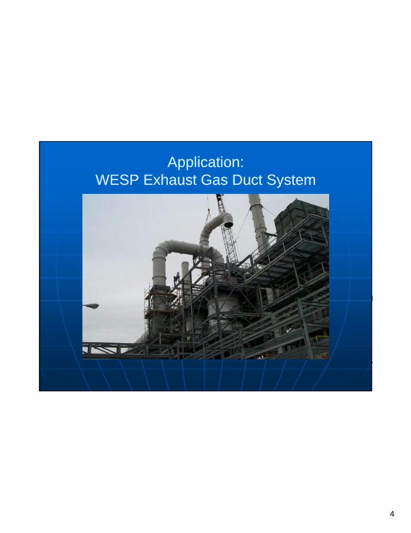
Application:Application:WESP Exhaust Gas Duct SystemWESP Exhaust Gas Duct System
5
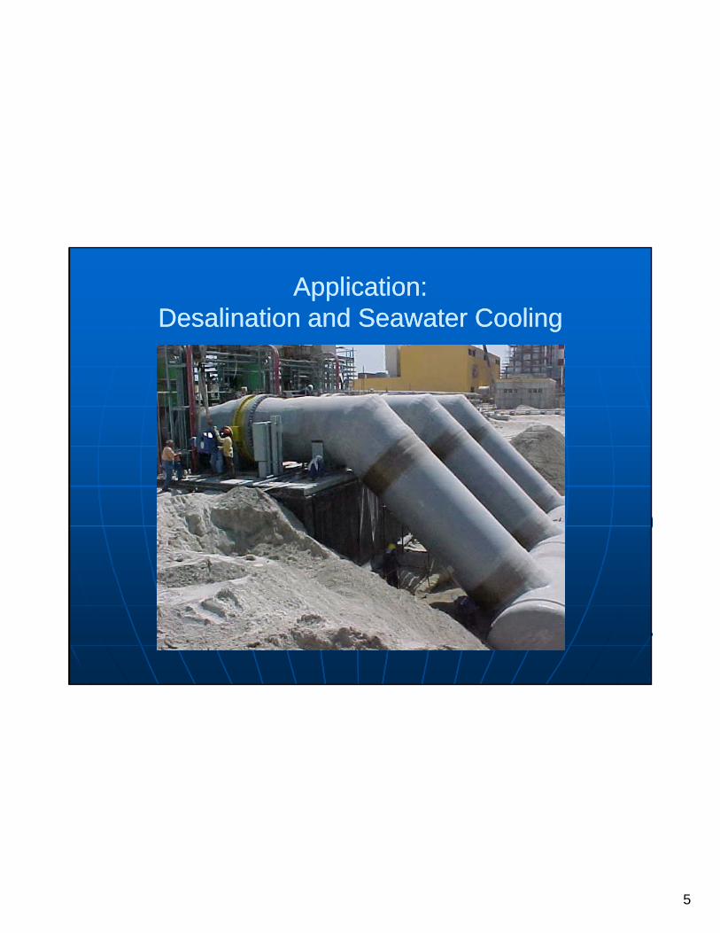
Application:Application:Desalination and Seawater CoolingDesalination and Seawater Cooling
6
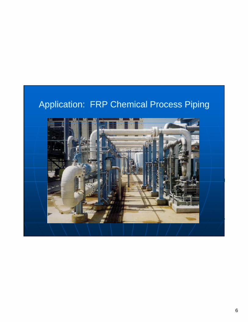
Application: FRP Chemical Process PipingApplication: FRP Chemical Process Piping
7
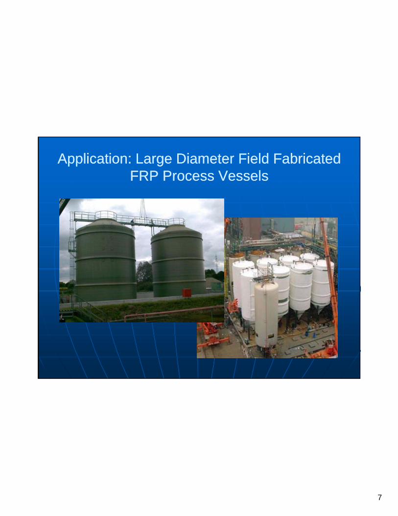
Application: Large Diameter Field Fabricated Application: Large Diameter Field Fabricated FRP Process VesselsFRP Process Vessels
8
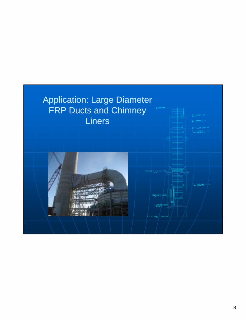
Application: Large Diameter Application: Large Diameter FRP Ducts and Chimney FRP Ducts and Chimney
LinersLinersLinersLiners

9
Where is FRP Used?Where is FRP Used?
PROCESS SYSTEMSPROCESS SYSTEMS•• Corrosive Fluids (Acids and Alkali)Corrosive Fluids (Acids and Alkali)•• Abrasive Applications (Slurry)Abrasive Applications (Slurry)•• 150 PSI or less150 PSI or less•• 250250°°F or lessF or less
WHY SHOULD WE ANALYZE IT?WHY SHOULD WE ANALYZE IT?
10
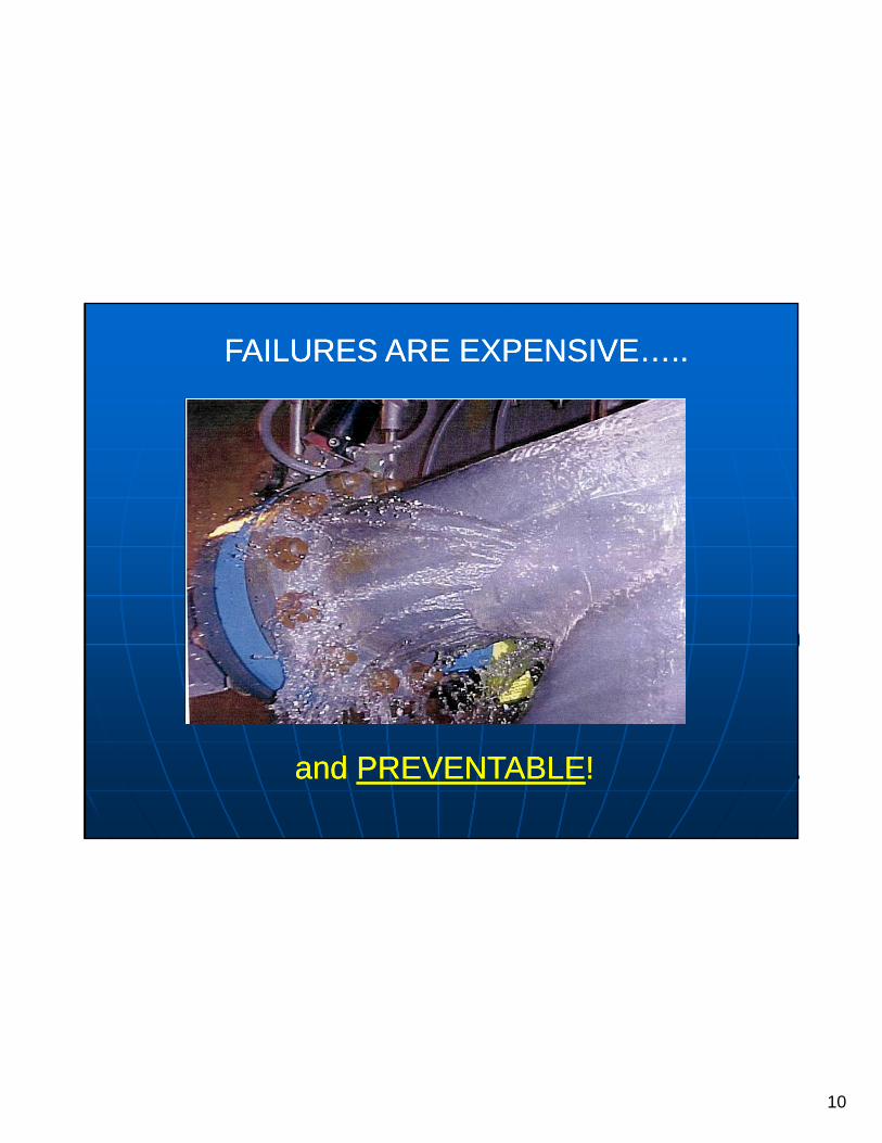
FAILURES ARE EXPENSIVE…..FAILURES ARE EXPENSIVE…..
and and PREVENTABLEPREVENTABLE!!

11
ALL MATERIALS DO NOT ALL MATERIALS DO NOT BEHAVE THE SAME IN A BEHAVE THE SAME IN A
SYSTEM?SYSTEM?
HOW ARE THEY DIFFERENT?HOW ARE THEY DIFFERENT?
12
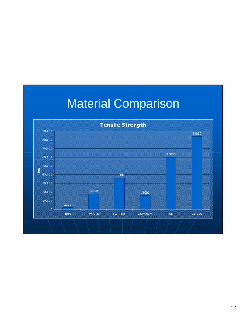
Material ComparisonMaterial Comparison
60000
84000
60,000
70,000
80,000
90,000
Tensile Strength
18000
36000
1600020,000
30,000
40,000
50,000
PS
I
2200
0
10,000
HDPE FW Axial FW Hoop Aluminum CS SS 316

13
Material ComparisonMaterial Comparison
29.528.3
25
30
35
Modulus of Elasticity at 70°F
28.827.7
25
30
35
Modulus of Elasticity at 180°F
0.171.4
10.2
5
10
15
20
PS
I×1
06
0.01.2
9.8
5
10
15
20
PS
I×1
06
0HDPE FW Aluminum CS SS 316
0 00
HDPE FW Aluminum CS SS 316
14
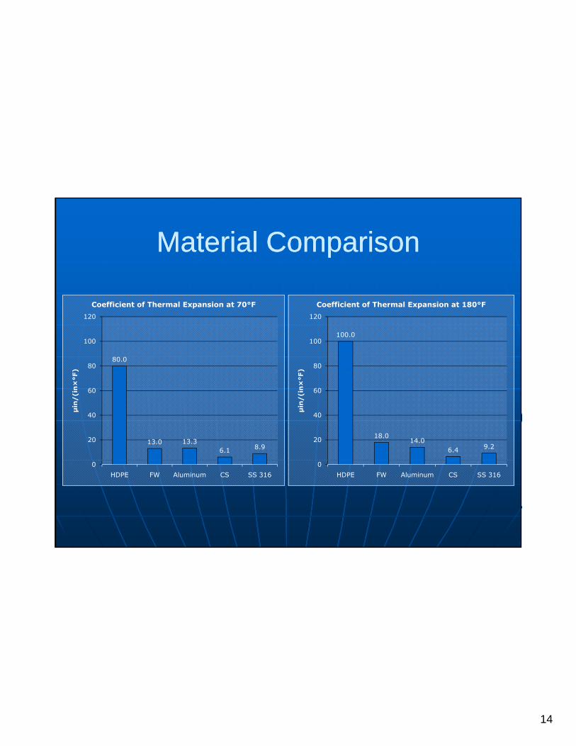
Material ComparisonMaterial Comparison
80.080
100
120
F)
Coefficient of Thermal Expansion at 70°F
100.0
80
100
120
F)Coefficient of Thermal Expansion at 180°F
13.0 13.36.1 8.9
20
40
60
μin
/(i
n×
°F
18.014.0
6.4 9.220
40
60
μin
/(i
n×
°F
0HDPE FW Aluminum CS SS 316
0HDPE FW Aluminum CS SS 316

15
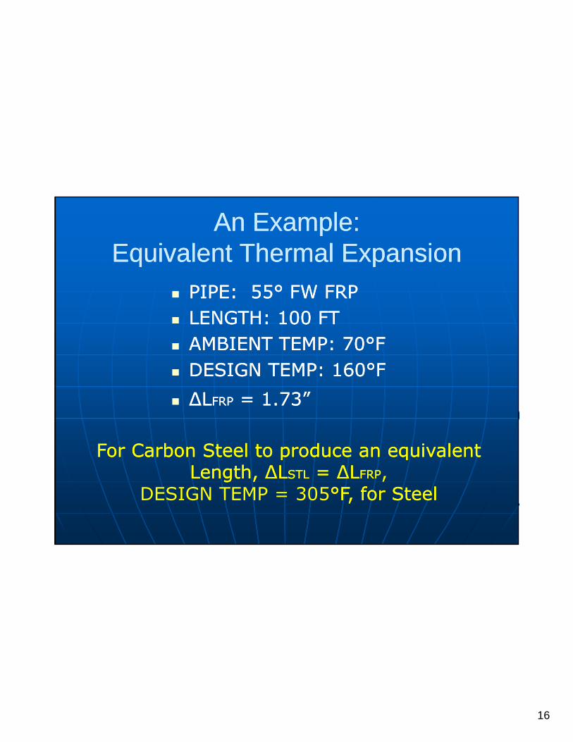
An Example: An Example: Equivalent Thermal Expansion Equivalent Thermal Expansion
PIPE: 55PIPE: 55°° FW FRPFW FRP LENGTH: 100 FTLENGTH: 100 FT AMBIENT TEMP: 70AMBIENT TEMP: 70°°FF OPERATING TEMP: 160OPERATING TEMP: 160°°FF ΔΔLLFRPFRP = 1.73” = 1.73”
16
An Example: An Example: Equivalent Thermal Expansion Equivalent Thermal Expansion
PIPE: 55PIPE: 55°° FW FRPFW FRP LENGTH: 100 FTLENGTH: 100 FT AMBIENT TEMP: 70AMBIENT TEMP: 70°°FF DESIGN TEMP: 160DESIGN TEMP: 160°°FF DESIGN TEMP: 160DESIGN TEMP: 160 FF ΔΔLLFRPFRP = 1.73”= 1.73”
For Carbon Steel to produce an equivalent For Carbon Steel to produce an equivalent p qp qLength, Length, ΔΔLLSTLSTL = = ΔΔLLFRPFRP,
DESIGN TEMP = 305°°F, for SteelF, for Steel

17
Analysis Design ApproachesAnalysis Design Approaches
CONSTRAINED SYSTEMCONSTRAINED SYSTEM
EXPANSION ABSORBING SYSTEMEXPANSION ABSORBING SYSTEM
FLEXIBLE SYSTEMFLEXIBLE SYSTEMFLEXIBLE SYSTEMFLEXIBLE SYSTEM

18
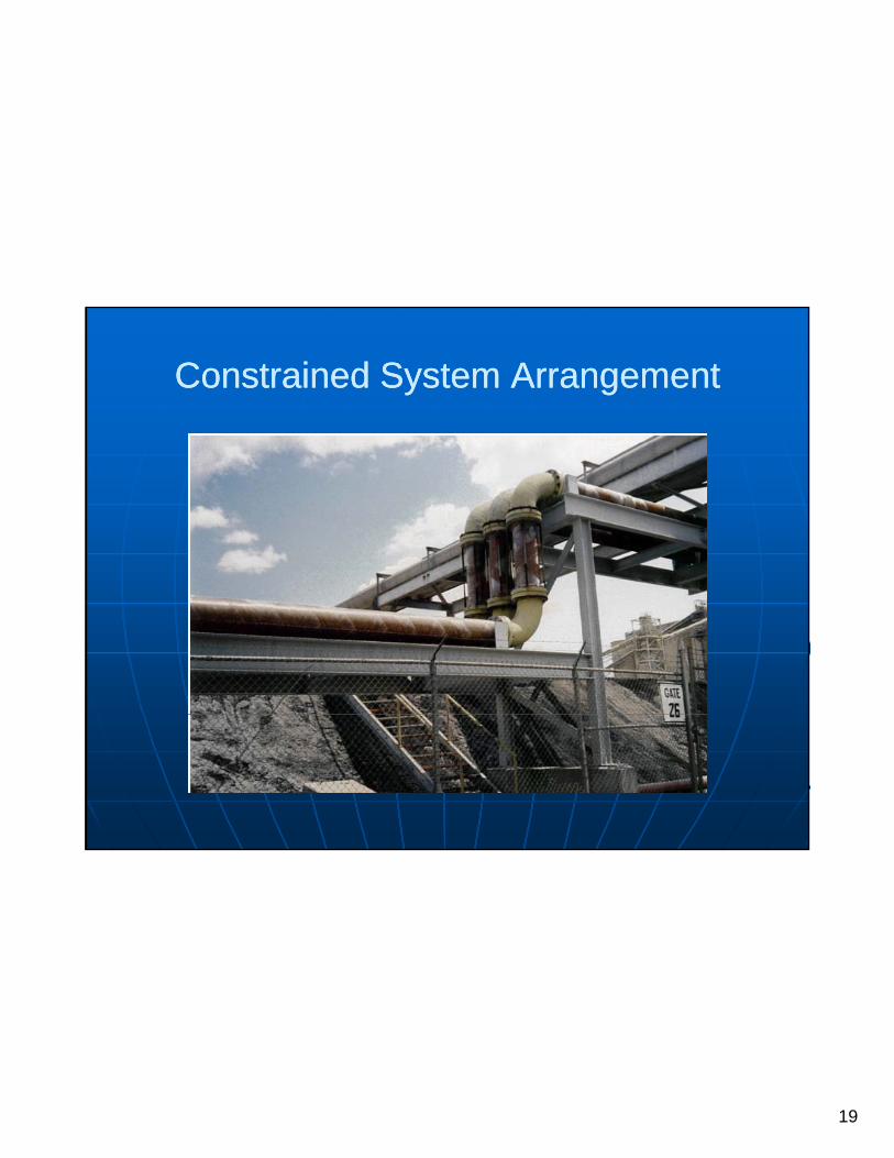
Constrained System ArrangementConstrained System Arrangement
19
Constrained System ArrangementConstrained System Arrangement

20
Constrained System ArrangementConstrained System Arrangement

21
Expansion Absorbing System ArrangementExpansion Absorbing System Arrangement

22
Flexible System ArrangementFlexible System Arrangement

23
Flexible System ArrangementFlexible System Arrangement

24
Design and Analysis Considerations
GeometryGeometry MaterialMaterial Design ConditionsDesign Conditions Load CasesLoad Cases
25
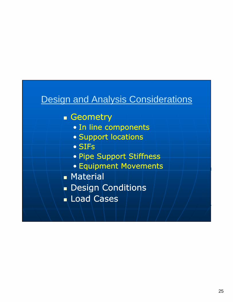
Design and Analysis Considerations
GeometryGeometry GeometryGeometry•• In In line componentsline components•• Support locationsSupport locations•• SIFsSIFs•• Pipe Pipe Support StiffnessSupport Stiffness•• Equipment MovementsEquipment Movements
MaterialMaterialDesign ConditionsDesign Conditions Design ConditionsDesign Conditions
Load CasesLoad Cases
26
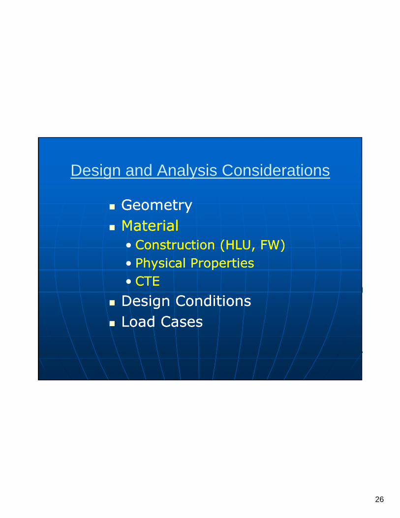
Design and Analysis Considerations
GeometryGeometry MaterialMaterial
•• Construction (HLU, FW)Construction (HLU, FW)Ph i l P tiPh i l P ti•• Physical PropertiesPhysical Properties
•• CTECTE Design ConditionsDesign Conditions
Load CasesLoad Cases Load CasesLoad Cases
27
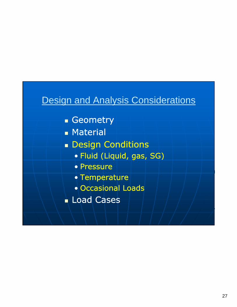
Design and Analysis Considerations
G tG t GeometryGeometry MaterialMaterial Design ConditionsDesign Conditions
Fl id (Li id SG)Fl id (Li id SG)•• Fluid (Liquid, gas, SG)Fluid (Liquid, gas, SG)•• PressurePressure•• TemperatureTemperature•• Occasional LoadsOccasional Loads•• Occasional LoadsOccasional Loads
Load CasesLoad Cases

28
Design and Analysis Considerations
G tG t GeometryGeometry MaterialMaterial Design ConditionsDesign Conditions
dd Load CasesLoad Cases•• DW + PressDW + Press•• DW + Press + TempDW + Press + Temp•• DW + Pressure + OccDW + Pressure + Occ•• DW + Pressure + OccDW + Pressure + Occ•• DW + Hydrostatic PressDW + Hydrostatic Press

29
System OptimizationSystem Optimization
30
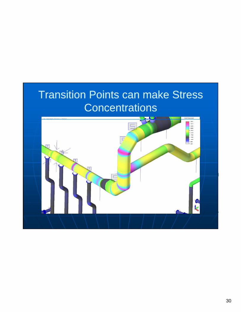
Transition Points can make Stress Transition Points can make Stress ConcentrationsConcentrations
31
The Purpose of the Pipe Supports:
Protect the PipeProtect the Pipe Assure Proper RestraintAssure Proper Restraint Assure Proper RestraintAssure Proper Restraint Assure System FunctionalityAssure System Functionality

32
CustomCustom--Designed SupportsDesigned Supports

33
Supports should be evaluated for Supports should be evaluated for Stress and Stiffness!Stress and Stiffness!
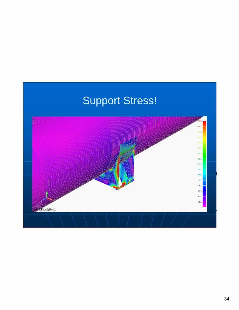
34
Support Stress!Support Stress!
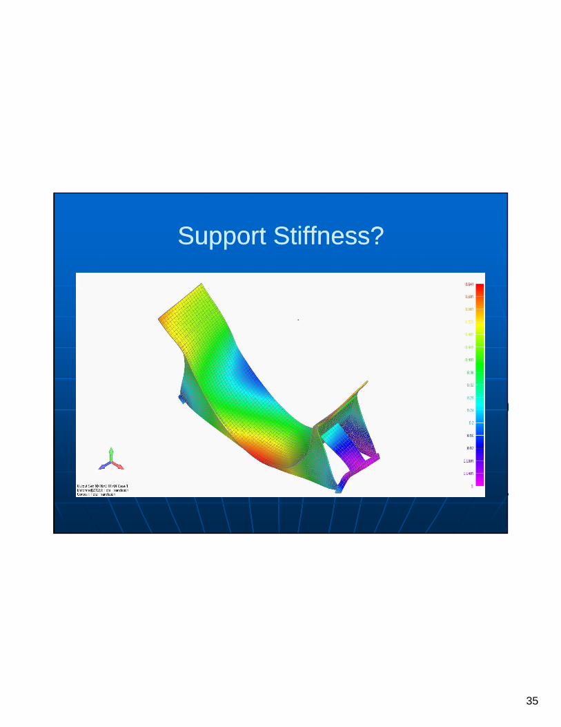
35
Support StiffnessSupport Stiffness??

36
InspectionInspection
InIn--process Shop process Shop QualityQuality ControlControl
On site Quality On site Quality AssuranceAssurance
37
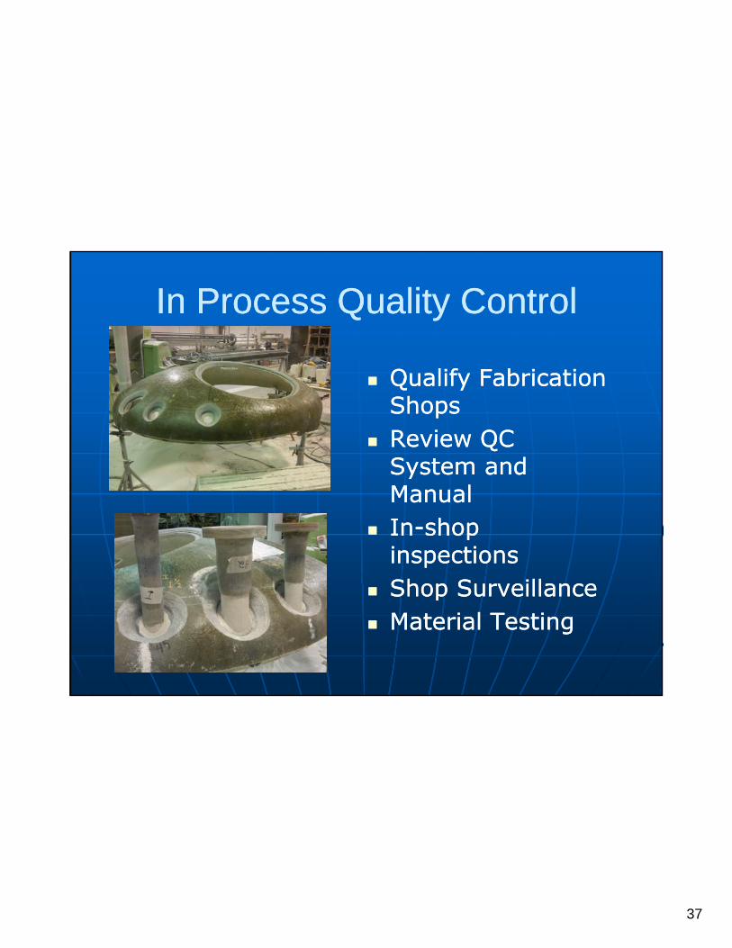
In Process Quality ControlIn Process Quality Control
Qualify Fabrication Qualify Fabrication ShopsShops
Review QC Review QC System and System and System and System and ManualManual
InIn--shop shop inspectionsinspectionsShop SurveillanceShop Surveillance Shop SurveillanceShop Surveillance
Material TestingMaterial Testing
38
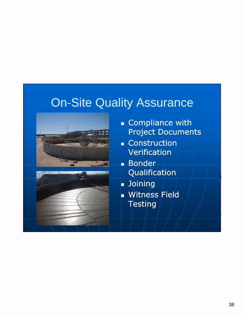
OnOn--Site Quality AssuranceSite Quality Assurance
C li ith C li ith Compliance with Compliance with Project DocumentsProject Documents
Construction Construction VerificationVerification
Bonder Bonder QualificationQualification
JoiningJoining Witness Field Witness Field Witness Field Witness Field
TestingTesting
39
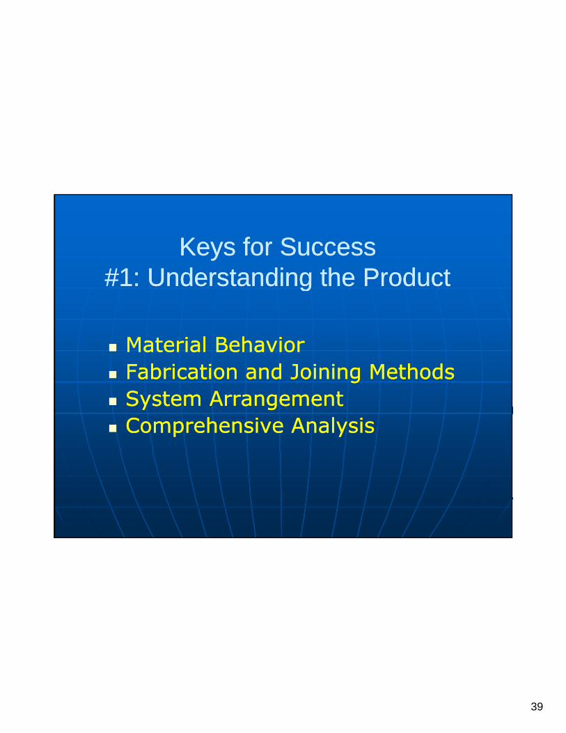
Keys for Success Keys for Success #1:#1: Understanding theUnderstanding the ProductProduct#1: #1: Understanding the Understanding the ProductProduct
Material BehaviorMaterial BehaviorF b i ti F b i ti d J i i M th dd J i i M th d Fabrication Fabrication and Joining Methodsand Joining Methods
System System ArrangementArrangement Comprehensive AnalysisComprehensive Analysis

40
Keys for SuccessKeys for Success#2: Communication#2: Communication
Support LoadsSupport LoadsO t Di tO t Di t Outer DiametersOuter Diameters
Fabrication TolerancesFabrication Tolerances
41
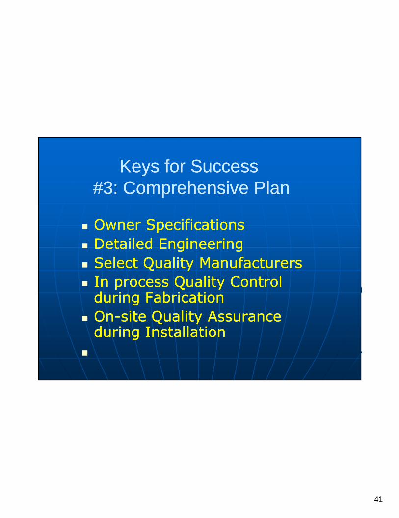
Keys for SuccessKeys for Success#3: Comprehensive Plan#3: Comprehensive Plan
Owner SpecificationsOwner Specifications Detailed EngineeringDetailed Engineering
S l t Q lit M f tS l t Q lit M f t Select Quality ManufacturersSelect Quality Manufacturers In process Quality Control In process Quality Control
during Fabricationduring Fabrication OnOn--site Quality Assurance site Quality Assurance OnOn site Quality Assurance site Quality Assurance
during Installationduring Installation

42
Thank YouThank You
Jeff Eisenman, P.E.Jeff Eisenman, P.E.Maverick Applied Science, Inc.Maverick Applied Science, Inc.
jeisenman@[email protected]: PH: +1(941+1(941) 721) 721--18001800