important - danddcc.com. important: contractor is ... nsn 7540-01-152-8070 30-105 standard form 30...
TRANSCRIPT

NAVFAC SPECIFICATION
6548691 Construct Blade Shop
Addition B-1794
MCAS Cherry Point, NC AMENDMENT #01
IMPORTANT
This amendment should be acknowledged when your proposal is submitted. Failure to acknowledge the amendment may constitute grounds for rejection of the proposal.
If your proposal has been submitted prior to the receipt of this amendment, acknowledgement should be made by telegram, which should state whether the price contained in your proposal is to remain unchanged, is to be decreased by an amount, or is to be increased by an amount. The acknowledgement must be received prior to proposal opening time.

AMENDMENT OF SOLICITATION/MODIFICATION OF CONTRACT 1. CONTRACT ID CODE PAGE OF PAGES
1 1 2. AMENDMENT/MODIFICATION NO. 3. EFFECTIVE DATE 4. REQUISITION/PURCHASE REQ. NO. 5. PROJECT NO. (If applicable)
01 1/10/2018 6548691 6. ISSUED BY Code N40085 7. ADMINISTERED BY (If other than item 6.) Code CG MCAS Cherry Point FACILITIES, ROICC B-163, CURTIS ROAD PSC BOX 8006
CHERRY POINT, NC 28533
8. NAME AND ADDRESS OF CONTRACTOR (No., street, county, State and ZIP Code) 9A. AMENDMENT OF SOLICITATION Construct Blade Shop Addition B-1794 9B. DATED (SEE ITEM 11)
AMENDMENT MUST BE ACKNOWLEDGED WITH YOUR PROPOSAL 10A. MODIFICATION OF CONTRACT/ORDER NO.
10B. DATED (SEE ITEM 13) CODE FACILITY CODE
11. THIS ITEM ONLY APPLIES TO AMENDMENTS OF SOLICITATIONS The above numbered solicitation is amended as set forth in item 14. The hour and date specified for receipt of Offers is extended is not extended. Offers must acknowledge receipt of this amendment prior to the hour and date specified in the solicitation or as amended, by one of the following methods: (a) By completing items 8 and 15, and returning 1 copy of the amendment; (b) By acknowledging receipt of this amendment on each copy of the offer submitted; or (c) By separate letter or telegram which includes a reference to the solicitation and amendment numbers. FAILURE OF YOUR ACKNOWLEDGMENT TO BE RECEIVED AT THE PLACE DESIGNATED FOR THE RECEIPT OF OFFERS PRIOR TO THE HOUR AND DATE SPECIFIED MAY RESULT IN REJECTION OF YOUR OFFER. If by virtue of this amendment you desire to change an offer already submitted, such change may be made by telegram or letter, provided each telegram or letter makes reference to the solicitation and this amendment, and is received prior to the opening hour and date specified.
12. ACCOUNTING AND APPROPRIATION DATA (if required)
13. THIS ITEM APPLIES ONLY TO MODIFICATIONS OF CONTRACTS/ORDERS, IT MODIFIES THE CONTRACT/ORDER NO. AS DESCRIBED IN ITEM 14.
A. THIS CHANGE ORDER IS ISSUED PURSUANT TO: (Specify authority) THE CHANGES SET FORTH IN ITEM 14. ARE MADE IN THE CONTRACT ORDER NO. IN ITEM 10A.
B. THE ABOVE NUMBERED CONTRACT/ORDER IS MODIFIED TO REFLECT THE ADMINISTRATION CHANGES (such as changes in paying office, appropriation date, etc.) SET FORTH IN ITEM 14, PURSUANT TO THE AUTHORITY OF FAR 43.103 (b).
C. THIS SUPPLEMENTAL AGREEMENT IS ENTERED INTO PURSUANT TO AUTHORITY OF:
D. OTHER: (specify type of modification and authority) E. IMPORTANT: Contractor is not is required to sign this document and return original to the issuing office. 14. DESCRIPTION OF AMENDMENT/MODIFICATION (Organized by UCF section headings, including solicitation/contract subject matter where feasible.) 6548691 – Construct Blade Shop Addition B-1794, FRC-East, Marine Corps Air Station Cherry Point, NC This amendment is being issued to provide the attached answers to RFIs. The Proposal due date of is extended to 17 Jan 2018 at 1200 local time. The deadline to submit RFIs has passed. See Attached
15A. NAME AND TITLE OF SIGNER (Type or print) 16A. NAME AND TITLE OF CONTRACTING OFFICER (Type or print) 15B. CONTRACTOR/OFFEROR (Same as Item 8) 15C. DATE SIGNED 16B. UNITED STATES OF AMERICA 16C. DATE SIGNED BY (Signature of person authorized to sign) (Signature of Contracting Officer) NSN 7540-01-152-8070 30-105 STANDARD FORM 30 (REV.1-83) 0224-3(10-90) PREVIOUS EDITION UNUSABLE Prescribed by GSA

Amendment 01 6548691 – Construct Blade Shop Addition B-1794
CONTINUATION SHEET SECTION 01 45 00.00 20, Quality Control is deleted and 01 45 00.00 20, Quality Control, dated 1/10/18, as shown in the footer, accompanies this Amendment. SECTION 08 33 23, Overhead Coiling Doors is deleted and 08 33 23, Overhead Coiling Doors, dated 1/10/18, as shown in the footer, accompanies this Amendment. SECTION 09 90 00, Paints and Coatings is deleted and 09 90 00, Paints and Coatings, dated 1/10/18, as shown in the footer, accompanies this Amendment. SECTION 00 01 15 – LIST OF DRAWINGS
1.2 CONTRACT DRAWINGS
Add the following to the list of drawings: NAVFAC DWG NO. TITLE SK-1 RFI #4 The following drawings are revised as of 1/9/18: NAVFAC DWG NO. TITLE 12729168 Electrical Diagrams and Panelboard Schedules, revised 1/9/18 These drawings accompany this Amendment.
Page 2 of 4

Amendment 01 6548691 – Construct Blade Shop Addition B-1794
RFI Response: 1. Paragraph 2.1.2 of specification 08 33 23 calls for insulated coiling doors. Door Schedule
shows Doors A101 and A107 as insulated, but not Door A106. Does Door A106 need to be insulated? Response: No. Refer to Door Schedule on NAVFAC Drawing Sheet 12729148 and revised Specification Section 08 33 23 Overhead Coiling Doors.
2. Paragraph 2.4 of specification 08 33 23 calls for electric operations. Are all coiling doors electrically operated? Door A106 does not have Note 5 next to it like the other doors on Drawing E101. Response: Door A106 is manually operated. Refer to New Work Plan – Power on NAVFAC Drawing Sheet 12729165 and revised Specification Section 08 33 23 Overhead Coiling Doors.
3. Note 5 on E101 calls for a 3 HP motor which greatly exceeds the manufacturer’s recommended motor size. Do motors need to be 3 HP or is manufacturer’s recommended HP acceptable? Response: Any deviations shall be reviewed and approved during the submittal process after construction award. Refer to New Work Notes on NAVFAC Drawing Sheet 12729165 and Panelboard P1, NAVFAC Drawing Sheet 12729168.
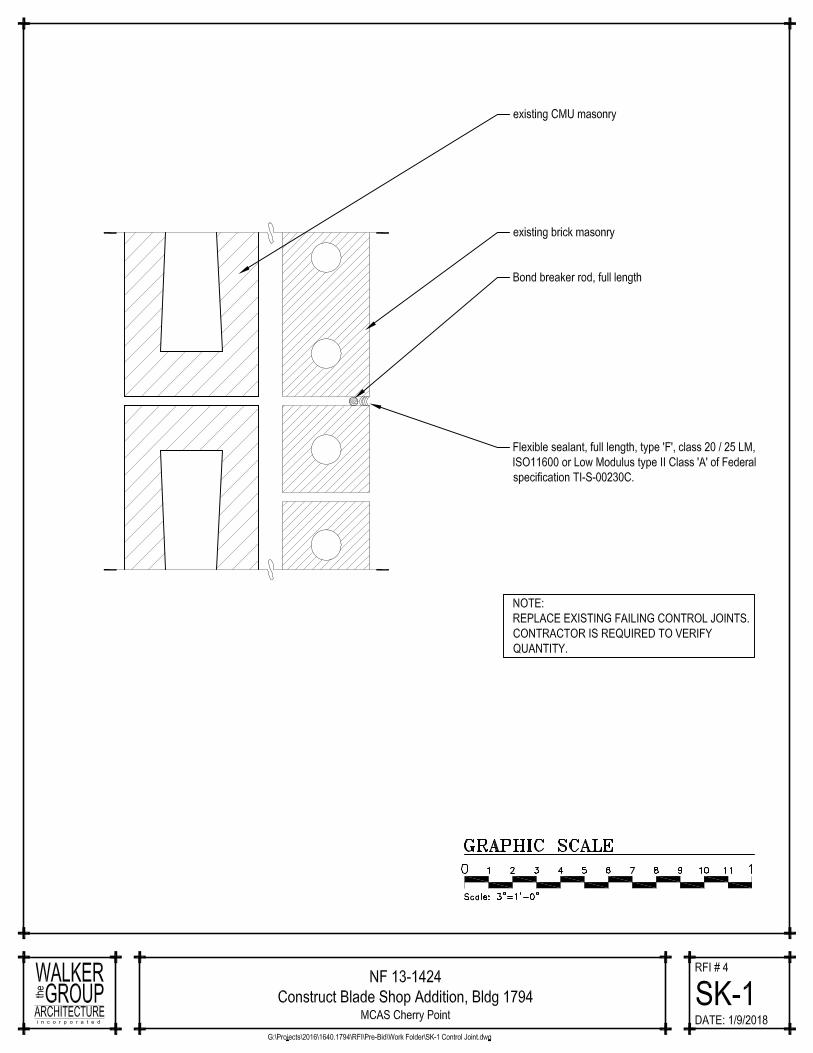
4. The existing control joints appear to be failing in a number of locations. The plans indicate to “provide moisture sealant on existing brick veneer” which typically requires that one power wash the exterior of the building. Please clarify if these joints need to be replaced. Response: Refer to Sketch SK-1.
5. The finish schedule on A-601 lists E. Paint (Epoxy Floor Paint) in the Bays and Janitor Closet. It lists Epoxy Floor and Epoxy in the Breakroom. We are assuming Section 09 67 23.13 Standard Resinous Flooring applies to the Breakroom. The Paints and Coatings Section does not identify an Epoxy Floor Paint. Please provide specifications for the products desired in these areas. Response: Refer to revised Specification Section 09 90 00 Paints and Coatings.
6. The finish schedule on A-601 lists E. Paint (Epoxy Floor Paint) in the Bays and Janitor Closet. It lists Epoxy Floor and Epoxy in the Breakroom. We are assuming Section 09 67 23.13 Standard Resinous Flooring applies to the Breakroom. The Paints and Coatings Section does not identify an Epoxy Floor Paint. Please provide specifications for the products desired in these areas. Response: Refer to revised Specification Section 09 90 00 Paints and Coatings.
7. The existing control joints appear to be failing in a number of locations. The plans indicate to “provide moisture sealant on existing brick veneer” which typically requires that one power wash the exterior of the building. Please clarify if these joints need to be replaced. Response: Refer to Sketch SK-1.
Page 3 of 4

Amendment 01 6548691 – Construct Blade Shop Addition B-1794
8. Section 01 35 26: Government Safety Requirements in para. 1.7.1.2 indicated the QC Mgr. can be the Supt. Section 01 45 00: Quality Control in para. 1.5.1.1 indicates the QC Mgr. can be the Supt. The Administrative Requirements in Section 01 30 00 do not reference Collateral Positions for QC / SSHO to Supt. No reference is in the RFP to Collateral Positions. Please confirm that the QC / SSHO are to be one position if duly qualified and the Supt. will be a separate (2nd) position for this contract. Response: The QC/SSHO can be the same person if duly qualified. Refer to Specification Section 01 35 26 Government Safety Requirements and Specification Section 01 45 00.00 20 Quality Control.
9. On the Construct Blade Shop Addition B-1794 , Project No. 6549691, the Qualifications (Section 01 45 00.00 20 Part 1.5.1.2) for the Quality Control (QC) Manager requires "a graduate of a four year accredited college or university program. with a minimum of 10 years' experience as a project Superintendent, QC Manager, Project Engineer or Construction Manager.." In order for us to provide the best possible proposal for the project, could the four year accredited college or program requirements be remove for the QC Manager? If not, would it be possible to restate the requirements, so the QC Manager will be require to have a four year accredited college or program or 10 years of experience? Response: Refer to revised Specification Section 01 45 00.00 20 Quality Control.
Page 4 of 4

CO
NS
TRU
CT
BLA
DE
SH
OP
AD
DIT
ION
A
T B
1794
AT
FRC
EA
ST
02-20-2017

CONSTRUCT BLADE SHOP, BUILDING 1794, FRC-EN40085-15-D4709, TASK ORDER 0014
SECTION 01 45 00.00 20
QUALITY CONTROL11/11
PART 1 GENERAL
1.1 REFERENCES
The publications listed below form a part of this specification to the extent referenced. The publications are referred to in the text by the basic designation only.
AMERICAN SOCIETY OF HEATING, REFRIGERATING AND AIR-CONDITIONING ENGINEERS (ASHRAE)
ASHRAE 52.2 (2012; Errata 2013; INT 1 2014; ADD A, B, AND D SUPP 2015; INT 3 2015; Errata 2 2015; ADD C 2015) Method of Testing General Ventilation Air-Cleaning Devices for Removal Efficiency by Particle Size
ASTM INTERNATIONAL (ASTM)
ASTM D6245 (2012) Using Indoor Carbon Dioxide Concentrations to Evaluate Indoor Air Quality and Ventilation
ASTM D6345 (2010) Selection of Methods for Active, Integrative Sampling of Volatile Organic Compounds in Air
SHEET METAL AND AIR CONDITIONING CONTRACTORS' NATIONAL ASSOCIATION (SMACNA)
ANSI/SMACNA 008 (2007) IAQ Guidelines for Occupied Buildings Under Construction, 2nd Edition
U.S. ARMY CORPS OF ENGINEERS (USACE)
EM 385-1-1 (2014) Safety and Health Requirements Manual
1.2 SUBMITTALS
Submit the following in accordance with Section 01 33 00 SUBMITTAL PROCEDURES
SD-01 Preconstruction Submittals
Construction Quality Control (QC) Plan
Submit a Construction QC Plan within 20 days after receipt of Notice of Award. The QC Plan shall include a preliminary submittal of the list of definable features of work that shall cover the first 90 days of construction.
SECTION 01 45 00.00 20 Page 11/10/18

CONSTRUCT BLADE SHOP, BUILDING 1794, FRC-EN40085-15-D4709, TASK ORDER 0014
1.3 INFORMATION FOR THE CONTRACTING OFFICER
Prior to commencing work on construction, the Contractor can obtain a single copy set of the current report forms from the Contracting Officer. The report forms will consist of the Contractor Production Report, Contractor Production Report (Continuation Sheet), Contractor Quality Control (CQC) Report, CQC Report (Continuation Sheet), Preparatory Phase Checklist, Initial Phase Checklist, Rework Items List, and Testing Plan and Log.
Deliver the following to the Contracting Officer during Construction:
a. CQC Report: Submit the report by 10:00 AM the next working day after each day that work is performed and for every seven consecutive calendar days of no-work.
b. Contractor Production Report: Submit the report by 10:00 AM the next working day after each day that work is performed and for every seven consecutive calendar days of no-work, attached to the CQC Report.
c. Preparatory Phase Checklist: Submit the report in the same manner as the CQC Report for each Preparatory Phase held.
d. Initial Phase Checklist: Submit the report in the same manner as the CQC Report for each Initial Phase held.
e. QC Specialist Reports: Submit the report by 10:00 AM the next working day after each day that work is performed.
f. Field Test Reports: Within two working days after the test is performed, submit the report as an attachment to the CQC Report.
g. Monthly Summary Report of Tests: Submit the report as an attachment to the CQC Report at the end of each month.
h. Testing Plan and Log: Submit the report as an attachment to the CQC Report, at the end of each month. Provide a copy of the final Testing Plan and Log to the OMSI preparer for inclusion into the OMSI documentation.
i. Rework Items List: Submit lists containing new entries daily, in the same manner as the CQC Report.
j. CQC Meeting Minutes: Within two working days after the meeting is held, submit the report as an attachment to the CQC Report.
k. QC Certifications: As required by the paragraph entitled "QC Certifications."
1.4 QC PROGRAM REQUIREMENTS
Establish and maintain a QC program as described in this section. This QC program is a key element in meeting the objectives of NAVFAC Commissioning. The QC program consists of a QC Organization, QC Plan, QC Plan Meeting(s), a Coordination and Mutual Understanding Meeting, QC meetings, three phases of control, submittal review and approval, testing, completion inspections, QC certifications, and documentation necessary to provide materials, equipment, workmanship, fabrication, construction and operations which comply with the requirements of this Contract. The QC
SECTION 01 45 00.00 20 Page 21/10/18

CONSTRUCT BLADE SHOP, BUILDING 1794, FRC-EN40085-15-D4709, TASK ORDER 0014
program must cover on-site and off-site work and be keyed to the work sequence. No construction work or testing may be performed unless the QC Manager is on the work site. The QC Manager must report to an officer of the firm and not be subordinate to the Project Superintendent or the Project Manager. The QC Manager, Project Superintendent and Project Manager must work together effectively. Although the QC Manager is the primary individual responsible for quality control, all individuals will be held responsible for the quality of work on the job.
1.4.1 Acceptance of the Construction Quality Control (QC) Plan
Acceptance of the QC Plan is required prior to the start of construction. The Contracting Officer reserves the right to require changes in the QC Plan and operations as necessary, including removal of personnel, to ensure the specified quality of work. The Contracting Officer reserves the right to interview any member of the QC organization at any time in order to verify the submitted qualifications. All QC organization personnel are subject to acceptance by the Contracting Officer. The Contracting Officer may require the removal of any individual for non-compliance with quality requirements specified in the Contract.
1.4.2 Preliminary Construction Work Authorized Prior to Acceptance
The only construction work that is authorized to proceed prior to the acceptance of the QC Plan is mobilization of storage and office trailers, temporary utilities, and surveying.
1.4.3 Notification of Changes
Notify the Contracting Officer, in writing, of any proposed changes in the QC Plan or changes to the QC organization personnel, a minimum of 10 work days prior to a proposed change. Proposed changes are subject to acceptance by the Contracting Officer.
1.5 QC ORGANIZATION
1.5.1 QC Manager
1.5.1.1 Duties
Provide a QC Manager at the work site to implement and manage the QC program, and to serve as the Site Safety and Health Officer (SSHO) as detailed in Section 01 35 26 GOVERNMENTAL SAFETY REQUIREMENTS. The QC Manager is required to attend the partnering meetings, QC Plan Meetings, Coordination and Mutual Understanding Meeting, conduct the QC meetings, perform the three phases of control , perform submittal review and certification, ensure testing is performed and provide QC certifications and documentation required in this Contract. The QC Manager is responsible for managing and coordinating the three phases of control and documentation performed by testing laboratory personnel and any other inspection and testing personnel required by this Contract. The QC Manager is the manager of all QC activities.
1.5.1.2 Qualifications
An individual with a minimum of 5 years combined experience in the following positions: Project Superintendent, QC Manager, Project Manager, Project Engineer or Construction Manager on similar size and type construction contracts which included the major trades that are part of
SECTION 01 45 00.00 20 Page 31/10/18

CONSTRUCT BLADE SHOP, BUILDING 1794, FRC-EN40085-15-D4709, TASK ORDER 0014
this Contract. The individual must have at least two years experience as a QC Manager. The individual must be familiar with the requirements of EM 385-1-1 , and have experience in the areas of hazard identification, safety compliance, and sustainability.
1.5.2 Construction Quality Management Training
In addition to the above experience and education requirements, the QC Manager must have completed the course entitled "Construction Quality Management (CQM) for Contractors." If the QC Manager does not have a current certification, they must obtain the CQM for Contractors course certification within 90 days of award. This course is periodically offered by the Naval Facilities Engineering Command and the Army Corps of Engineers. Contact the Contracting Officer for information on the next scheduled class.
1.5.3 Alternate QC Manager Duties and Qualifications
Designate an alternate for the QC Manager at the work site to serve in the event of the designated QC Manager's absence. The period of absence may not exceed two weeks at one time, and not more than 30 workdays during a calendar year. The qualification requirements for the Alternate QC Manager must be the same as for the QC Manager.
1.5.4 Registered Fire Protection Engineer
The U.S. Registered Fire Protection Engineer (FPE) must be an independent third party hired directly by the Prime Contractor as an integral part of the Prime Contractor's Quality Control Organization. This FPE must have no business relationships (owner, partner, operating officer, distributor, salesman, or technical representative) with any subcontractors involved with this project, or with any fire protection equipment device manufacturers, suppliers or installers for any such equipment provided as part of this project. This FPE is responsible for review, approval, and coordination of all fire protection system material submittals, calculations, shop drawings, etc.
1.6 QUALITY CONTROL (QC) PLAN
1.6.1 Construction Quality Control (QC) Plan
1.6.1.1 Requirements
Provide, for acceptance by the Contracting Officer, a Construction QC Plan submitted in a three-ring binder that includes a table of contents, with major sections identified with tabs, with pages numbered sequentially, and that documents the proposed methods and responsibilities for accomplishing quality control commissioning activities during the construction of the project:
a. QC ORGANIZATION: A chart showing the QC organizational structure.
b. NAMES AND QUALIFICATIONS: Names and qualifications, in resume format, for each person in the QC organization. Include the CQM for Contractors course certifications for the QC Manager and Alternate QC Manager as required by the paragraphs entitled "Construction Quality Management Training" and "Alternate QC Manager Duties and Qualifications".
SECTION 01 45 00.00 20 Page 41/10/18
CONSTRUCT BLADE SHOP, BUILDING 1794, FRC-EN40085-15-D4709, TASK ORDER 0014
c. DUTIES, RESPONSIBILITY AND AUTHORITY OF QC PERSONNEL: Duties, responsibilities, and authorities of each person in the QC organization.
d. OUTSIDE ORGANIZATIONS: A listing of outside organizations, such as architectural and consulting engineering firms, that will be employed by the Contractor and a description of the services these firms will provide.
e. APPOINTMENT LETTERS: Letters signed by an officer of the firm appointing the QC Manager and Alternate QC Manager and stating that they are responsible for implementing and managing the QC program as described in this Contract. Include in this letter the responsibility of the QC Manager and Alternate QC Manager to implement and manage the three phases of control, and their authority to stop work which is not in compliance with the Contract. Letters of direction are to be issued by the QC Manager to the Assistant QC Manager outlining their duties, authorities, and responsibilities. Include copies of the letters in the QC Plan.
f. SUBMITTAL PROCEDURES AND INITIAL SUBMITTAL REGISTER: Procedures for reviewing, approving, and managing submittals. Provide the name(s) of the person(s) in the QC organization authorized to review and certify submittals prior to submitting for approval. Provide the initial submittal of the Submittal Register as specified in Section 01 33 00 SUBMITTAL PROCEDURES.
g. TESTING LABORATORY INFORMATION: Testing laboratory information required by the paragraphs entitled "Accreditation Requirements", as applicable.
h. TESTING PLAN AND LOG: A Testing Plan and Log that includes the tests required, referenced by the specification paragraph number requiring the test, the frequency, and the person responsible for each test. Use Government forms to log and track tests.
i. PROCEDURES TO COMPLETE REWORK ITEMS: Procedures to identify, record, track, and complete rework items. Use Government forms to record and track rework items.
j. DOCUMENTATION PROCEDURES: Use Government form.
k. LIST OF DEFINABLE FEATURES: A Definable Feature of Work (DFOW) is a task that is separate and distinct from other tasks and has control requirements and work crews unique to that task. A DFOW is identified by different trades or disciplines and is an item or activity on the construction schedule. Include in the list of DFOWs, but not be limited to, all critical path activities on the construction schedule. Include all activities for which this specification requires QC Specialists or specialty inspection personnel. Provide separate DFOWs in the construction schedule for each design development stage and submittal package.
l. PROCEDURES FOR PERFORMING THE THREE PHASES OF CONTROL: Identify procedures used to ensure the three phases of control to manage the quality on this project. For each DFOW, a Preparatory and Initial phase checklist will be filled out during the Preparatory and Initial phase meetings. Conduct the Preparatory and Initial Phases and meetings with a view towards obtaining quality construction by
SECTION 01 45 00.00 20 Page 51/10/18

CONSTRUCT BLADE SHOP, BUILDING 1794, FRC-EN40085-15-D4709, TASK ORDER 0014
planning ahead and identifying potential problems for each DFOW.
m. PERSONNEL MATRIX: A personnel matrix showing for each section of the specification who will review and certify submittals, who will perform and document the three phases of control, and who will perform and document the testing.
n. PROCEDURES FOR COMPLETION INSPECTION: Procedures for identifying and documenting the completion inspection process. Include in these procedures the responsible party for punch out inspection, pre-final inspection, and final acceptance inspection.
o. TRAINING PROCEDURES AND TRAINING LOG: Procedures for coordinating and documenting the training of personnel required by the Contract.
p. ORGANIZATION AND PERSONNEL CERTIFICATIONS LOG: Procedures for coordinating, tracking and documenting all certifications on subcontractors, testing laboratories, suppliers, personnel, etc. QC Manager will ensure that certifications are current, appropriate for the work being performed, and will not lapse during any period of the contract that the work is being performed.
1.7 COORDINATION AND MUTUAL UNDERSTANDING MEETING
After submission of the QC Plan, and prior to Government approval and the start of construction, the QC Manager will meet with the Contracting Officer to present the QC program required by this Contract. When a new QC Manager is appointed, the coordination and mutual understanding meeting must be repeated.
1.7.1 Purpose
The purpose of this meeting is to develop a mutual understanding of the QC details, including documentation, administration for on-site and off-site work, design intent, environmental requirements and procedures, coordination of activities to be performed, and the coordination of the Contractor's management, production, and QC personnel. At the meeting, the Contractor will be required to explain in detail how three phases of control will be implemented for each DFOW, as well as how each DFOW will be affected by each management plan or requirement as listed below:
a. Waste Management Plan.
b. IAQ Management Plan.
c. Procedures for noise and acoustics management.
d. Environmental Protection Plan.
e. Environmental regulatory requirements.
1.7.2 Coordination of Activities
Coordinate activities included in various sections to assure efficient and orderly installation of each component. Coordinate operations included under different sections that are dependent on each other for proper installation and operation. Schedule construction operations with consideration for indoor air quality as specified in the IAQ Management Plan.
SECTION 01 45 00.00 20 Page 61/10/18

CONSTRUCT BLADE SHOP, BUILDING 1794, FRC-EN40085-15-D4709, TASK ORDER 0014
1.7.3 Attendees
As a minimum, the Contractor's personnel required to attend include an officer of the firm, the Project Manager, Project Superintendent, QC Manager, Alternate QC Manager,, Environmental Manager, and subcontractor representatives. Each subcontractor who will be assigned QC responsibilities must have a principal of the firm at the meeting. Minutes of the meeting will be prepared by the QC Manager and signed by the Contractor and the Contracting Officer. Provide a copy of the signed minutes to all attendees and include in the QC Plan.
1.8 QC MEETINGS
After the start of construction, conduct QC meetings once every two weeks by the QC Manager at the work site with the Project Superintendent, and the foremen who are performing the work of the DFOWs. The QC Manager is to prepare the minutes of the meeting and provide a copy to the Contracting Officer within two working days after the meeting. The Contracting Officer may attend these meetings. As a minimum, accomplish the following at each meeting:
a. Review the minutes of the previous meeting.
b. Review the schedule and the status of work and rework.
c. Review the status of submittals.
d. Review the work to be accomplished in the next two weeks and documentation required.
e. Resolve QC and production problems (RFI, etc.).
f. Address items that may require revising the QC Plan.
g. Review Accident Prevention Plan (APP).
h. Review environmental requirements and procedures.
i. Review Waste Management Plan.
j. Review IAQ Management Plan.
k. Review Environmental Management Plan.
l. Review the status of training completion.
1.9 THREE PHASES OF CONTROL
Adequately cover both on-site and off-site work with the Three Phases of Control and include the following for each DFOW.
1.9.1 Preparatory Phase
Notify the Contracting Officer at least two work days in advance of each preparatory phase meeting. The meeting will be conducted by the QC Manager and attended by the Project Superintendent, and the foreman responsible for the DFOW. When the DFOW will be accomplished by a
SECTION 01 45 00.00 20 Page 71/10/18

CONSTRUCT BLADE SHOP, BUILDING 1794, FRC-EN40085-15-D4709, TASK ORDER 0014
subcontractor, that subcontractor's foreman must attend the preparatory phase meeting. Document the results of the preparatory phase actions in the daily CQC Report and in the Preparatory Phase Checklist. Perform the following prior to beginning work on each DFOW:
a. Review each paragraph of the applicable specification sections.
b. Review the Contract drawings.
c. Verify that field measurements are as indicated on construction and/or shop drawings before confirming product orders, in order to minimize waste due to excessive materials.
d. Verify that appropriate shop drawings and submittals for materials and equipment have been submitted and approved. Verify receipt of approved factory test results, when required.
e. Review the testing plan and ensure that provisions have been made to provide the required QC testing.
f. Examine the work area to ensure that the required preliminary work has been completed.
g. Coordinate the schedule of product delivery to designated prepared areas in order to minimize site storage time and potential damage to stored materials.
h. Arrange for the return of shipping/packaging materials, such as wood pallets, where economically feasible.
i. Examine the required materials, equipment and sample work to ensure that they are on hand and conform to the approved shop drawings and submitted data and are properly stored.
j. Discuss specific controls used and construction methods, construction tolerances, workmanship standards, and the approach that will be used to provide quality construction by planning ahead and identifying potential problems for each DFOW.
k. Review the APP and appropriate AHA to ensure that applicable safety requirements are met, and that required material Safety Data Sheets (SDS) are submitted.
1.9.2 Initial Phase
Notify the Contracting Officer at least two work days in advance of each initial phase. When construction crews are ready to start work on a DFOW, conduct the initial phase with the Project Superintendent, and the foreman responsible for that DFOW. Observe the initial segment of the DFOW to ensure that the work complies with Contract requirements. Document the results of the initial phase in the daily CQC Report and in the Initial Phase Checklist. Repeat the initial phase for each new crew to work on-site, or when acceptable levels of specified quality are not being met. Perform the following for each DFOW:
a. Establish level of workmanship and verify that it meets the minimum acceptable workmanship standards. Compare with required sample panels as appropriate.
SECTION 01 45 00.00 20 Page 81/10/18

CONSTRUCT BLADE SHOP, BUILDING 1794, FRC-EN40085-15-D4709, TASK ORDER 0014
b. Resolve any workmanship issues.
c. Ensure that testing is performed by the approved laboratory.
d. Check work procedures for compliance with the APP and the appropriate AHA to ensure that applicable safety requirements are met.
e. Review project specific work plans (i.e. HAZMAT Abatement, Stormwater Management) to ensure all preparatory work items have been completed and documented.
1.9.3 Follow-Up Phase
Perform the following for on-going work daily, or more frequently as necessary, until the completion of each DFOW and document in the daily CQC Report:
a. Ensure the work is in compliance with Contract requirements.
b. Maintain the quality of workmanship required.
c. Ensure that testing is performed by the approved laboratory.
d. Ensure that rework items are being corrected.
e. Assure manufacturers representatives have performed necessary inspections if required and perform safety inspections.
1.9.4 Additional Preparatory and Initial Phases
Conduct additional preparatory and initial phases on the same DFOW if the quality of on-going work is unacceptable, if there are changes in the applicable QC organization, if there are changes in the on-site production supervision or work crew, if work on a DFOW is resumed after substantial period of inactivity, or if other problems develop.
1.9.5 Notification of Three Phases of Control for Off-Site Work
Notify the Contracting Officer at least two weeks prior to the start of the preparatory and initial phases.
1.10 SUBMITTAL REVIEW AND APPROVAL
Procedures for submission, review and approval of submittals are described in Section 01 33 00 SUBMITTAL PROCEDURES.
1.11 TESTING
Except as stated otherwise in the specification sections, perform sampling and testing required under this Contract.
1.11.1 Accreditation Requirements
Construction materials testing laboratories must be accredited by a laboratory accreditation authority and will be required to submit a copy of the Certificate of Accreditation and Scope of Accreditation. The laboratory's scope of accreditation must include the appropriate ASTM standards (E 329, C 1077, D 3666, D 3740, A 880, E 543) listed in the technical sections of the specifications. Laboratories engaged in Hazardous Materials Testing must meet the requirements of OSHA and EPA.
SECTION 01 45 00.00 20 Page 91/10/18

CONSTRUCT BLADE SHOP, BUILDING 1794, FRC-EN40085-15-D4709, TASK ORDER 0014
The policy applies to the specific laboratory performing the actual testing, not just the Corporate Office.
1.11.2 Laboratory Accreditation Authorities
Laboratory Accreditation Authorities include the National Voluntary Laboratory Accreditation Program (NVLAP) administered by the National Institute of Standards and Technology at http://ts.nist.gov/ts/htdocs/210/214/214.htm , the American Association of State Highway and Transportation Officials (AASHTO) program athttp://www.amrl.net/amrlsitefinity/default/aap.aspx , International Accreditation Services, Inc. (IAS) at http://www.iasonline.org , U. S. Army Corps of Engineers Materials Testing Center (MTC) at http://gsl.erdc.usace.army.mil/SL/MTC/ , and the American Association for Laboratory Accreditation (A2LA) program at http://www.a2la.org/ .
1.11.3 Capability Check
The Contracting Officer retains the right to check laboratory equipment in the proposed laboratory and the laboratory technician's testing procedures, techniques, and other items pertinent to testing, for compliance with the standards set forth in this Contract.
1.11.4 Test Results
Cite applicable Contract requirements, tests or analytical procedures used. Provide actual results and include a statement that the item tested or analyzed conforms or fails to conform to specified requirements. If the item fails to conform, notify the Contracting Officer immediately. Conspicuously stamp the cover sheet for each report in large red letters "CONFORMS" or "DOES NOT CONFORM" to the specification requirements, whichever is applicable. Test results must be signed by a testing laboratory representative authorized to sign certified test reports. Furnish the signed reports, certifications, and other documentation to the Contracting Officer via the QC Manager. Furnish a summary report of field tests at the end of each month, in accordance with paragraph INFORMATION FOR THE CONTRACTING OFFICER.
1.11.5 Test Reports and Monthly Summary Report of Tests
Furnish the signed reports, certifications, and a summary report of field tests at the end of each month to the Contracting Officer. Attach a copy of the summary report to the last daily CQC Report of each month. Provide a copy of the signed test reports and certifications to the OMSI preparer for inclusion into the OMSI documentation.
1.12 QC CERTIFICATIONS
1.12.1 CQC Report Certification
Contain the following statement within the CQC Report: "On behalf of the Contractor, I certify that this report is complete and correct and equipment and material used and work performed during this reporting period is in compliance with the contract drawings and specifications to the best of my knowledge, except as noted in this report."
1.12.2 Invoice Certification
Furnish a certificate to the Contracting Officer with each payment
SECTION 01 45 00.00 20 Page 101/10/18

CONSTRUCT BLADE SHOP, BUILDING 1794, FRC-EN40085-15-D4709, TASK ORDER 0014
request, signed by the QC Manager, attesting that as-built drawings are current, coordinated and attesting that the work for which payment is requested, including stored material, is in compliance with Contract requirements.
1.12.3 Completion Certification
Upon completion of work under this Contract, the QC Manager must furnish a certificate to the Contracting Officer attesting that "the work has been completed, inspected, tested and is in compliance with the Contract." Provide a copy of this final QC Certification for completion to the OMSI preparer for inclusion into the OMSI documentation.
1.13 COMPLETION INSPECTIONS
1.13.1 Punch-Out Inspection
Near the completion of all work or any increment thereof, established by a completion time stated in the Contract Clause entitled "Commencement, Prosecution, and Completion of Work," or stated elsewhere in the specifications, the QC Manager must conduct an inspection of the work and develop a "punch list" of items which do not conform to the approved drawings, specifications and Contract. Include in the punch list any remaining items on the "Rework Items List", which were not corrected prior to the Punch-Out Inspection. Include within the punch list the estimated date by which the deficiencies will be corrected. Provide a copy of the punch list to the Contracting Officer. The QC Manager, or staff, must make follow-on inspections to ascertain that all deficiencies have been corrected. Once this is accomplished, notify the Government that the facility is ready for the Government "Pre-Final Inspection".
1.13.2 Pre-Final Inspection
The Government and QCM will perform this inspection to verify that the facility is complete and ready to be occupied. A Government "Pre-Final Punch List" will be documented by the QCM as a result of this inspection. The QC Manager will ensure that all items on this list are corrected prior to notifying the Government that a "Final" inspection with the Client can be scheduled. Any items noted on the "Pre-Final" inspection must be corrected in a timely manner and be accomplished before the contract completion date for the work,or any particular increment thereof, if the project is divided into increments by separate completion dates.
1.13.3 Final Acceptance Inspection
Notify the Contracting Officer at least 14 calendar days prior to the date a final acceptance inspection can be held. State within the notice that all items previously identified on the pre-final punch list will be corrected and acceptable, along with any other unfinished Contract work, by the date of the final acceptance inspection. The Contractor must be represented by the QC Manager, the Project Superintendent, and others deemed necessary. Attendees for the Government will include the Contracting Officer, other FEAD personnel, and personnel representing the Client. Failure of the Contractor to have all contract work acceptably complete for this inspection will be cause for the Contracting Officer to bill the Contractor for the Government's additional inspection cost in accordance with the Contract Clause entitled "Inspection of Construction."
SECTION 01 45 00.00 20 Page 111/10/18
CONSTRUCT BLADE SHOP, BUILDING 1794, FRC-EN40085-15-D4709, TASK ORDER 0014
1.14 DOCUMENTATION
Maintain current and complete records of on-site and off-site QC program operations and activities.
1.14.1 Construction Documentation
Reports are required for each day that work is performed and must be attached to the CQC Report prepared for the same day. Maintain current and complete records of on-site and off-site QC program operations and activities. The forms identified under the paragraph "INFORMATION FOR THE CONTRACTING OFFICER" will be used. Reports are required for each day work is performed. Account for each calendar day throughout the life of the Contract. Every space on the forms must be filled in. Use N/A if nothing can be reported in one of the spaces. The Project Superintendent and the QC Manager must prepare and sign the Contractor Production and CQC Reports, respectively. The reporting of work must be identified by terminology consistent with the construction schedule. In the "remarks" sections of the reports, enter pertinent information including directions received, problems encountered during construction, work progress and delays, conflicts or errors in the drawings or specifications, field changes, safety hazards encountered, instructions given and corrective actions taken, delays encountered and a record of visitors to the work site, QC problem areas, deviations from the QC Plan, construction deficiencies encountered, meetings held. For each entry in the report(s), identify the Schedule Activity No. that is associated with the entered remark.
1.14.2 Quality Control Validation
Establish and maintain the following in a series of three ring binders. Binders must be divided and tabbed as shown below. These binders must be readily available to the Contracting Officer during all business hours.
a. All completed Preparatory and Initial Phase Checklists, arranged by specification section.
b. All milestone inspections, arranged by Activity Number.
c. An up-to-date copy of the Testing Plan and Log with supporting field test reports, arranged by specification section.
d. Copies of all contract modifications, arranged in numerical order. Also include documentation that modified work was accomplished.
e. An up-to-date copy of the Rework Items List.
f. Maintain up-to-date copies of all punch lists issued by the QC staff to the Contractor and Sub-Contractors and all punch lists issued by the Government.
1.14.3 Testing Plan and Log
As tests are performed, the QC Manager will record on the "Testing Plan and Log" the date the test was performed and the date the test results were forwarded to the Contracting Officer. Attach a copy of the updated "Testing Plan and Log" to the last daily CQC Report of each month, per the paragraph "INFORMATION FOR THE CONTRACTING OFFICER". Provide a copy of the final "Testing Plan and Log" to the OMSI preparer for inclusion into
SECTION 01 45 00.00 20 Page 121/10/18

CONSTRUCT BLADE SHOP, BUILDING 1794, FRC-EN40085-15-D4709, TASK ORDER 0014
the OMSI documentation.
1.14.4 Rework Items List
The QC Manager must maintain a list of work that does not comply with the Contract, identifying what items need to be reworked, the date the item was originally discovered, the date the item will be corrected by, and the date the item was corrected. There is no requirement to report a rework item that is corrected the same day it is discovered. Attach a copy of the "Rework Items List" to the last daily CQC Report of each month. The Contractor is responsible for including those items identified by the Contracting Officer.
1.14.5 As-Built Drawings
The QC Manager is required to ensure the as-built drawings, required by Section 01 78 00 CLOSEOUT SUBMITTALS are kept current on a daily basis and marked to show deviations which have been made from the Contract drawings. Ensure each deviation has been identified with the appropriate modifying documentation (e.g. PC No., Modification No., Request for Information No., etc.). The QC Manager must initial each revision. Upon completion of work, the QC Manager will furnish a certificate attesting to the accuracy of the as-built drawings prior to submission to the Contracting Officer.
1.15 NOTIFICATION ON NON-COMPLIANCE
The Contracting Officer will notify the Contractor of any detected non-compliance with the Contract. Take immediate corrective action after receipt of such notice. Such notice, when delivered to the Contractor at the work site, is deemed sufficient for the purpose of notification. If the Contractor fails or refuses to comply promptly, the Contracting Officer may issue an order stopping all or part of the work until satisfactory corrective action has been taken. No part of the time lost due to such stop orders will be made the subject of claim for extension of time for excess costs or damages by the Contractor.
1.16 CONSTRUCTION INDOOR AIR QUALITY (IAQ) MANAGEMENT PLAN
Submit an IAQ Management Plan within 15 days after notice to proceed and not less than 10 days before the preconstruction meeting. Revise and resubmit Plan as required by the Contracting Officer. Make copies of the final plan available to all workers on site. Include provisions in the Plan to meet the requirements specified below and to ensure safe, healthy air for construction workers and building occupants.
1.16.1 Requirements During Construction
Provide for evaluation of indoor Carbon Dioxide concentrations in accordance with ASTM D6245. Provide for evaluation of volatile organic compounds (VOCs) in indoor air in accordance with ASTM D6345. Use filters with a Minimum Efficiency Reporting Value (MERV) of 8 in permanently installed air handlers during construction.
1.16.1.1 Control Measures
Meet or exceed the requirements of ANSI/SMACNA 008 , Chapter 3, to help minimize contamination of the building from construction activities. The five requirements of this manual which must be adhered to are described
SECTION 01 45 00.00 20 Page 131/10/18

CONSTRUCT BLADE SHOP, BUILDING 1794, FRC-EN40085-15-D4709, TASK ORDER 0014
below:
a. HVAC protection: Isolate return side of HVAC system from surrounding environment to prevent construction dust and debris from entering the duct work and spaces.
b. Source control: Use low emitting paints and other finishes, sealants, adhesives, and other materials as specified. When available, cleaning products must have a low VOC content and be non-toxic to minimize building contamination. Utilize cleaning techniques that minimize dust generation. Cycle equipment off when not needed. Prohibit idling motor vehicles where emissions could be drawn into building. Designate receiving/storage areas for incoming material that minimize IAQ impacts.
c. Pathway interruption: When pollutants are generated use strategies such as 100 percent outside air ventilation or erection of physical barriers between work and non-work areas to prevent contamination.
d. Housekeeping: Clean frequently to remove construction dust and debris. Promptly clean up spills. Remove accumulated water and keep work areas dry to discourage the growth of mold and bacteria. Take extra measures when hazardous materials are involved.
e. Scheduling: Control the sequence of construction to minimize the absorption of VOCs by other building materials.
1.16.1.2 Moisture Contamination
a. Remove accumulated water and keep work dry.
b. Use dehumidification to remove moist, humid air from a work area .
c. Do not use combustion heaters or generators inside the building.
d. Protect porous materials from exposure to moisture.
e. Remove and replace items which remain damp for more than a few hours.
1.16.2 Requirements after Construction
After construction ends and prior to occupancy, conduct a building flush-out or test the indoor air contaminant levels. Flush-out must be a minimum two-weeks with MERV-13 filtration media as determined by ASHRAE 52.2 at 100 percent outside air. Air contamination testing must be consistent with EPA's current Compendium of Methods for the Determination of Air Pollutants in Indoor Air. After building flush-out or testing and prior to occupancy, replace filtration media. Filtration media must have a MERV of 13 as determined by ASHRAE 52.2 .
PART 2 PRODUCTS
Not Used
PART 3 EXECUTION
3.1 PREPARATION
Designate receiving/storage areas for incoming material to be delivered
SECTION 01 45 00.00 20 Page 141/10/18

CONSTRUCT BLADE SHOP, BUILDING 1794, FRC-EN40085-15-D4709, TASK ORDER 0014
according to installation schedule and to be placed convenient to work area in order to minimize waste due to excessive materials handling and misapplication. Store and handle materials in a manner as to prevent loss from weather and other damage. Keep materials, products, and accessories covered and off the ground, and store in a dry, secure area. Prevent contact with material that may cause corrosion, discoloration, or staining. Protect all materials and installations from damage by the activities of other trades.
-- End of Section --
SECTION 01 45 00.00 20 Page 151/10/18

NF 13-1424 Const. Blade Shop Add., Bldg 1794
SECTION 08 33 23
OVERHEAD COILING DOORS07/07
PART 1 GENERAL
1.1 REFERENCES
The publications listed below form a part of this specification to the extent referenced. The publications are referred to within the text by the basic designation only.
AMERICAN SOCIETY OF CIVIL ENGINEERS (ASCE)
ASCE 7-10 (2010) Minimum Design Loads for Buildings and Other Structures
AMERICAN SOCIETY OF HEATING, REFRIGERATING AND AIR-CONDITIONING ENGINEERS (ASHRAE)
ASHRAE FUN IP (2009; Errata 2010) Fundamentals Handbook, I-P Edition
ASME INTERNATIONAL (ASME)
ASME B29.400 (2001; R 2008) Combination, "H" Type Mill Chains, and Sprockets
ASTM INTERNATIONAL (ASTM)
ASTM A153/A153M (2009) Standard Specification for Zinc Coating (Hot-Dip) on Iron and Steel Hardware
ASTM A27/A27M (2010) Standard Specification for Steel Castings, Carbon, for General Application
ASTM A307 (2010) Standard Specification for Carbon Steel Bolts and Studs, 60 000 PSI Tensile Strength
ASTM A36/A36M (2008) Standard Specification for Carbon Structural Steel
ASTM A48/A48M (2003; R 2008) Standard Specification for Gray Iron Castings
ASTM A53/A53M (2012) Standard Specification for Pipe, Steel, Black and Hot-Dipped, Zinc-Coated, Welded and Seamless
ASTM A653/A653M (2015) Standard Specification for Steel Sheet, Zinc-Coated (Galvanized) or Zinc-Iron Alloy-Coated (Galvannealed) by the Hot-Dip Process
ASTM A666 (2010) Standard Specification for Annealed
SECTION 08 33 23 Page 11/10/18

NF 13-1424 Const. Blade Shop Add., Bldg 1794
or Cold-Worked Austenitic Stainless Steel Sheet, Strip, Plate and Flat Bar
ASTM A780/A780M (2009) Standard Practice for Repair of Damaged and Uncoated Areas of Hot-Dip Galvanized Coatings
ASTM A924/A924M (2014) Standard Specification for General Requirements for Steel Sheet, Metallic-Coated by the Hot-Dip Process
ASTM B221 (2008) Standard Specification for Aluminum and Aluminum-Alloy Extruded Bars, Rods, Wire, Profiles, and Tubes
ASTM B221M (2007) Standard Specification for Aluminum and Aluminum-Alloy Extruded Bars, Rods, Wire, Profiles, and Tubes (Metric)
ASTM D 2000 (2008) Standard Classification System for Rubber Products in Automotive Applications
ASTM E 330 (2002; R 2010) Structural Performance of Exterior Windows, Doors, Skylights and Curtain Walls by Uniform Static Air Pressure Difference
ASTM E 84 (2010b) Standard Test Method for Surface Burning Characteristics of Building Materials
ASTM F 568M (2007) Standard Specification for Carbon and Alloy Steel Externally Threaded Metric Fasteners
NATIONAL ELECTRICAL MANUFACTURERS ASSOCIATION (NEMA)
NEMA ICS 2 (2000; Errata 2006; R 2005; Errata 2008) Standard for Controllers, Contactors, and Overload Relays Rated 600 V
NEMA ICS 6 (1993; R 2001; R 2006) Standard for Enclosures
NEMA MG 1 (2009) Motors and Generators
NATIONAL FIRE PROTECTION ASSOCIATION (NFPA)
NFPA 70 (2011; TIA 11-1; Errata 2011) National Electrical Code
1.2 DESCRIPTION
Overhead coiling doors to be counterbalanced doors by methods of manufacturer's standard mechanism with an adjustable-tension, steel helical torsion spring mounted around a steel shaft and contained in a spring barrel connected to top of curtain with barrel rings. Use grease-sealed or self-lubricating bearings for rotating members. Doors to be coiling type, with interlocking slats, complete with anchoring and door hardware, guides,
SECTION 08 33 23 Page 21/10/18

NF 13-1424 Const. Blade Shop Add., Bldg 1794
hood, and operating mechanisms, and designed for use on openings as indicated.
1.3 PERFORMANCE REQUIREMENTS
1.3.1 Wind Loading
Design and fabricate door assembly to withstand the wind loading pressure of at least 47.5 pounds per square foot with a maximum deflection of 1/120 of the opening width. Provide test data showing compliance with ASTM E 330. Sound engineering principles may be used to interpolate or extrapolate test results to door sizes not specifically tested Complete assembly must meet or exceed the requirements of ASCE 7-10.
1.3.2 Operational Cycle Life
All portions of the door, hardware and operating mechanism that are subject to movement, wear, or stress fatigue must be designed to operate through a minimum number of 10 cycles per day. One complete cycle of door operation is defined as when the door is in the closed position, moves to the fully open position, and returns to the closed position.
1.4 SUBMITTALS
Submit the following in accordance with Section 01 33 00 SUBMITTAL PROCEDURES:
SD-02 Shop Drawings
Provide fabrication drawings that show complete assembly with hardware and framing details for the following items:
Overhead Coiling Doors
Counterbalancing Mechanism
Manual Door Operators
Electric Door Operators
Bottom Bar
Guides
Mounting Brackets
Overhead Drum
Painting
Submit Installation Drawings in accordance with paragraph entitled, "Overhead Coiling Door Assemblies," of this section.
SD-03 Product Data
Submit manufacturer's catalog data for the following items listing all accessories including supports, locks and latches, and weather
SECTION 08 33 23 Page 31/10/18
NF 13-1424 Const. Blade Shop Add., Bldg 1794
stripping.
Overhead Coiling Doors
Hardware
Counterbalancing Mechanism
Manual Door Operators
Electric Door Operators
SD-05 Design Data
Submit equipment and performance data for the following items in accordance with the paragraph entitled, "Performance Requirements," of this section.
Overhead Coiling Doors
Hardware
Counterbalancing Mechanism
Manual Door Operators
Electric Door Operators
SD-10 Operation and Maintenance Data
Submit Operation and Maintenance Manuals for Overhead Coiling Door Assemblies , including the following items:
Materials
Devices
Procedures
Manufacture's Brochures
Parts Lists
Cleaning
1.5 OVERHEAD COILING DOOR DETAIL SHOP DRAWINGS
Provide installation drawings for overhead coiling door assemblies which show elevations of each door type, shape and thickness of materials, finishes, details of joints and connections, and details of guides and fittings, rough opening dimensions, location and description of hardware, anchorage locations, and counterbalancing mechanism and door operator details. Show locations of replaceable fusible links wiring diagrams for power, signal and controls. Include a schedule showing the location of each door with the drawings.
Contractor must submit 6 copies of the Operation and Maintenance Manuals 30 calendar days prior to testing the Overhead Coiling Door Assemblies. Update and resubmit data for final approval no later than 30 calendar days
SECTION 08 33 23 Page 41/10/18

NF 13-1424 Const. Blade Shop Add., Bldg 1794
prior to contract completion.
Provide operation and maintenance manuals which are consistent with manufacturer's standard brochures, schematics, printed instructions, general operating procedures, and safety precautions. Provide test data that is legible and of good quality.
1.6 WARRANTY, OPERATION AND MAINTENANCE DATA
Submit Operation and Maintenance Manuals for Overhead Coiling Door Assemblies, including the following items:
Materials
Devices
Manual Door Operators
Electric Door Operators
Painting
Procedures
Manufacture's Brochures
Parts Lists
Contractor must furnish a written guarantee that the helical spring and counterbalance mechanism are free from defects in material and workmanship and that they will remain so for not less than two years after completion and acceptance of the project.
Contractor must warrant that upon notification by the Government, he will immediately make good any defects in material, workmanship, and door operation within the same time period covered by the guarantee, at no cost to the Government.
1.7 DELIVERY AND STORAGE
Delivered doors to the jobsite wrapped in a protective covering with the brands and names clearly marked thereon. Store doors in a dry location that is adequately ventilated and free from dirt and dust, water, and other contaminants, and in a manner that permits easy access for inspection and handling.
PART 2 PRODUCTS
2.1 OVERHEAD COILING DOORS
2.1.1 Curtain Materials and Construction
Provide curtain slats which are fabricated from steel sheets conforming to ASTM A653/A653M, Grade A, with the additional requirement of a minimum yield point of 33,000 psi. Provide sheets which are galvanized in accordance with ASTM A653/A653M and ASTM A924/A924M.
Fabricate doors from interlocking cold-rolled slats, with section profiles as specified, designed to withstand the specified wind loading. Provide
SECTION 08 33 23 Page 51/10/18

NF 13-1424 Const. Blade Shop Add., Bldg 1794
slats which are continuous without splices for the width of the door.
2.1.2 Non-Insulated Curtains (Door A106)
Form Curtains from manufacturer's standard shapes of interlocking slats.
2.1.3 Insulated Curtains (Door A101, A107)
Form Curtains from manufacturer's standard shapes of interlocking slats. Supply slat system with a minimum R-value of 4 when calculated in accordance with ASHRAE FUN IP. Slats to consist of a polystyrene core not less than 11/16 inch thick, completely enclosed within metal facings. Exterior face of slats must be the same gauge as specified for curtains. Interior face must be not lighter than 0.0219 inches. The insulated slat assembly is to have a flame spread rating of not more than 25 and a smoke development factor of not more than 50 when tested in accordance with ASTM E 84.
2.1.4 Curtain Bottom Bar
Curtain bottom bars must be pairs of angles from the manufacturer's standard steel, stainless and aluminum extrusions not less than 2.0 by 2.0 inches by 0.188 inch. Steel extrusions must conform to ASTM A36/A36M. Stainless steel extrusions conforming to ASTM A666, Type 304. Aluminum extrusions conforming to ASTM B221 or(ASTM B221M). Galvanize angles and fasteners in accordance with ASTM A653/A653M and ASTM A924/A924M. Coat welds and abrasions with paint conforming to ASTM A780/A780M.
2.1.5 Locks
Provide end and/or wind locks of cast steel conforming to ASTM A27/A27M, Grade B; galvanized in accordance with ASTM A653/A653M, ASTM A153/A153M and ASTM A924/A924M and secured at every other curtain slat.
2.1.6 Weather Stripping
Weather-stripping at the door-head and jamb must be 1/8-inch thick sheet of natural or neoprene rubber with air baffles, secured to the insides of hoods with galvanized-steel fasteners through continuous galvanized-steel pressure bars at least 5/8-inch wide and 1/8-inch thick.
Threshold weather-stripping must be 1/8-inch thick sheet natural or neoprene rubber secured to the bottom bars.
Provide weather-stripping of natural or neoprene rubber conforming to ASTM D 2000.
2.1.7 Locking Devices
Slide Bolt to engage through slots in tracks for locking by padlock, located on both left and right jamb sides, operable from coil side.
2.1.8 Safety Interlock
Equip power-operated doors with safety interlock switch to disengage power supply when door is locked.
SECTION 08 33 23 Page 61/10/18

NF 13-1424 Const. Blade Shop Add., Bldg 1794
2.1.9 Overhead Drum
Fabricate drums from nominal 0.028-inch thick, hot-dip galvanized steel sheet with G90 (Z275) zinc coating, complying with ASTM A653/A653M.
2.2 HARDWARE
All hardware must conform to ASTM A153/A153M, ASTM A307, ASTM F 568M, and ASTM A27/A27M.
2.2.1 Guides
Fabricate curtain jamb guides from the manufacturer's standard angles or channels of same material and finish as curtain slats unless otherwise indicated, with sufficient depth and strength to retain curtain, to allow curtain to operate smoothly, and to withstand loading. Slot bolt holes for track adjustment.
2.2.2 Equipment Supports
Fabricate door-operating equipment supports from the manufacturer's standard steel shapes and plates conforming to ASTM A36/A36M, galvanized in accordance with ASTM A653/A653M and ASTM A924/A924M. Size the shapes and plates in accordance with the industry standards for the size, weight, and type of door installation..
2.3 COUNTERBALANCING MECHANISM
Counterbalance doors by means of manufacturer's standard mechanism with an adjustable-tension, steel helical torsion spring mounted around a steel shaft and contained in a spring barrel connected to top of curtain with barrel rings. Use grease-sealed or self-lubricating bearings for rotating members.
2.3.1 Brackets
Provide the manufacturer's standard mounting brackets of either cast iron or cold-rolled steel with one located at each end of the counterbalance barrel conforming to ASTM A48/A48M.
2.3.2 Counterbalance Barrels
Fabricate spring barrel of manufacturer's standard hot-formed, structural-quality, welded or seamless carbon-steel pipe, conforming to ASTM A53/A53M, of sufficient diameter and wall thickness to support rolled-up curtain without distortion of slats and to limit barrel deflection to not more than 0.03 inch per foot of span under full load.
2.3.3 Spring Balance
One or more oil-tempered, heat-treated steel helical torsion springs installed within the barrel capable of producing sufficient torque to assure easy operation of the door curtain. Provide and size springs to counterbalance weight of curtain, with uniform adjustment accessible from outside barrel. Secure ends of springs to barrel and shaft with cast-steel barrel plugs.
SECTION 08 33 23 Page 71/10/18

NF 13-1424 Const. Blade Shop Add., Bldg 1794
2.3.4 Torsion Rod for Counter Balance
Fabricate rod from the manufacturer's standard cold-rolled steel, sized to hold fixed spring ends and carry torsional load.
2.4 MANUAL DOOR OPERATORS (Door A106)
2.4.1 Manual Chain-Hoist Door Operators
Provide door operators which consist of an endless steel hand chain, chain-pocket wheel, guard, and a geared reduction unit of at least a 3 to 1 ratio with a maximum 25 lbf required pull for operation must not exceed 35 pounds.
Provide chain hoists to have a self-locking mechanism allowing the curtain to be stopped at any point in its upward or downward travel and to remain in that position until moved to the fully open or closed position. Provide hand chains of cadmium-plated alloy steel conforming to ASME B29.400. Yield point of the chain must be at least three times the required hand-chain pull.
Provide chain sprocket wheels of cast iron conforming to ASTM A48/A48M.
2.5 ELECTRIC DOOR OPERATORS
See Electrical Div 26 for electrical requirements.
Provide electrical wiring and door operating controls conforming to the applicable requirements of NFPA 70.
Electric door-operator assemblies must be the sizes and capacities recommended and provided by the door manufacturer for specified doors. Assemblies must be complete with electric motors and factory-prewired motor controls, starter, gear reduction units, solenoid-operated brakes, clutch, remote-control stations, manual or automatic control devices, and accessories as required for proper operation of the doors.
Design the operators so that motors may be removed without disturbing the limit-switch adjustment and affecting the emergency auxiliary operators.
Provide a manual operator of crank-gear or chain-gear mechanisms with a release clutch to permit manual operation of doors in case of power failure. Arrange the emergency manual operator so that it may be put into and out of operation from floor level, and its use will not affect the adjustment of the limit switches. Provide an electrical or mechanical device which will automatically disconnect the motor from the operating mechanism when the emergency manual operating mechanism is engaged.
2.5.1 Door-Operator Types
Provide an operator which is mounted to the right or left door head plate with the operator on top of the door-hood assembly and connected to the door drive shaft with drive chain and sprockets. Headroom is required for this type of mounting.
2.5.2 Electric Motors
Provide motors which are the high-starting-torque, reversible, constant-duty electrical type with overload protection of sufficient torque
SECTION 08 33 23 Page 81/10/18

NF 13-1424 Const. Blade Shop Add., Bldg 1794
and horsepower to move the door in either direction from any position and produce a door-travel speed of not less than 8 nor more than 12 inches per second without exceeding thehorsepower rating.
Provide motors which conform to NEMA MG 1 designation, temperature rating, service factor, enclosure type, and efficiency to the requirements specified.
2.5.3 Motor Bearings
Bearings must be bronze-sleeve or heavy-duty ball or roller antifriction type with full provisions for the type of thrust imposed by the specific duty load.
Pre-lubricate and factory seal bearings in motors less than 1/2 horsepower.
Equip motors coupled to worm-gear reduction units with either ball or roller bearings.
Equip bearings in motors 1/2 horsepower or larger with lubrication service fittings. Fit lubrication fittings with color-coded plastic or metal dust caps.
In any motor, bearings that are lubricated at the factory for extended duty periods do not need to be lubricated for a given number of operating hours. Display this information on an appropriate tag or label on the motor with instructions for lubrication cycle maintenance.
2.5.4 Motor Starters, Controls, and Enclosures
Each door motor must have a factory-wired, unfused, disconnect switch; a reversing, across-the-line magnetic starter with thermal overload protection; 120-volt operating coils with a control transformer limit switch; and a safety interlock assembled in a NEMA ICS 6 type enclosure as specified herein. Control equipment must conform to NEMA ICS 2.
Provide adjustable switches, electrically interlocked with the motor controls and set to stop the door automatically at the fully open and fully closed position.
2.5.5 Control Enclosures
Provide control enclosures that conform to NEMA ICS 6 for general purpose NEMA Type 1.
2.5.6 Safety-Edge Device
Provide each door with a pneumatic safety device extending the full width of the door and located within a U-section neoprene or rubber astragal mounted on the bottom rail of the bottom door section. Device must immediately stop and reverse the door upon contact with an obstruction in the door opening during downward travel and cause the door to return to full-open position. Safety device is not a substitute for a limit switch.
Connect safety device to the control circuit through a retracting safety cord and reel.
SECTION 08 33 23 Page 91/10/18

NF 13-1424 Const. Blade Shop Add., Bldg 1794
2.5.7 Speed-Reduction Units
Provide speed-reduction units consisting of hardened-steel worm and bronze worm gear assemblies running in oil or grease and encased in a sealed casing, coupled to the motor through a flexible coupling. Drive shafts must rotate on ball- or roller-bearing assemblies that are integral with the unit.
Provide minimum ratings of speed reduction units which are in accordance with AGMA provisions for class of service.
Ground worm gears to provide accurate thread form; machine teeth for all other types of gearing. Surface harden all gears.
Provide bearings which are the antifriction type equipped with oil seals.
2.5.8 Brakes
Provide brakes which are 360-degree shoe brakes or shoe and drum brakes, solenoid-operated and electrically interlocked to the control circuit to set automatically when power is interrupted.
2.5.9 Clutches
Clutches must be the 4-inch diameter, multiple face, externally adjustable friction type or adjustable centrifugal type.
2.6 SURFACE FINISHING
Comply with NAAMM's "Metal Finishes Manual for Architectural and Metal Products" for recommendations for applying and designating finishes. Noticeable variations in the same metal component are not acceptable. Variations in appearance of adjoining components are acceptable if they are within the range of approved samples and are assembled or installed to minimize contrast.
PART 3 EXECUTION
3.1 GENERAL
Install overhead coiling door assembly, anchors and inserts for guides, brackets, motors, switches, hardware, and other accessories in accordance with approved detail drawings and manufacturer's written instructions. Upon completion of installation, doors must be free from all distortion.
Install overhead coiling doors, motors, hoods, and operators at the mounting locations as indicated for each door in the contract documents and as required by the manufacturer.
Install overhead coiling doors, switches, and controls along accessible routes in compliance with regulatory requirements for accessibility and as required by the manufacturer.
3.2 FIELD PAINTED FINISH
Steel doors and frames which are to be field painted must accordance with Section 09 90 00 PAINTS AND COATINGS and manufacturer's written instructions. Protect weather stripping from paint. Finishes must be free of scratches or other blemishes.
SECTION 08 33 23 Page 101/10/18
NF 13-1424 Const. Blade Shop Add., Bldg 1794
3.3 ACCEPTANCE PROVISIONS
After installation, adjust hardware and moving parts. Lubricate bearings and sliding parts as recommended by manufacturer to provide smooth operating functions for ease movement, free of warping, twisting, or distortion of the door assembly.
Adjust seals to provide weather-tight fit around entire perimeter.
Engage a factory-authorized service representative to perform startup service and checks according to manufacturer's written instructions.
Test the door opening and closing operation when activated by controls or alarm-connected fire-release system. Adjust controls and safeties. Replace damaged and malfunctioning controls and equipment. Reset door-closing mechanism after successful test.
Test and make final adjustment of new doors at no additional cost to the Government.
3.3.1 Maintenance and Adjustment
Not more than 90 calendar days after completion and acceptance of the project, the Contractor must examine, lubricate, test, and re-adjust doors as required for proper operation.
3.3.2 CLEANING
Clean doors in accordance with manufacturer's approved instructions.
-- End of Section --
SECTION 08 33 23 Page 111/10/18
Construct Blade Shop Addition, Bldg 1794 16303
SECTION 09 90 00
PAINTS AND COATINGS08/08
PART 1 GENERAL
1.1 REFERENCES
The publications listed below form a part of this specification to the extent referenced. The publications are referred to within the text by the basic designation only.
AMERICAN CONFERENCE OF GOVERNMENTAL INDUSTRIAL HYGIENISTS (ACGIH)
ACGIH 0100Doc (2005) Documentation of the Threshold Limit Values and Biological Exposure Indices
ASME INTERNATIONAL (ASME)
ASME A13.1 (2007) Scheme for the Identification of Piping Systems
ASTM INTERNATIONAL (ASTM)
ASTM D 2092 (1995; R 2001e1) Standard Guide for Preparation of Zinc-Coated (Galvanized) Steel Surfaces for Painting
ASTM D 235 (2002; R 2008) Mineral Spirits (Petroleum Spirits) (Hydrocarbon Dry Cleaning Solvent)
ASTM D 4214 (2007) Standard Test Method for Evaluating the Degree of Chalking of Exterior Paint Films
ASTM D 4263 (1983; R 2005) Indicating Moisture in Concrete by the Plastic Sheet Method
ASTM D 4444 (2008) Use and Calibration of Hand-Held Moisture Meters
ASTM D 523 (2008) Standard Test Method for Specular Gloss
ASTM F 1869 (2004) Measuring Moisture Vapor Emission Rate of Concrete Subfloor Using Anhydrous Calcium Chloride
MASTER PAINTERS INSTITUTE (MPI)
MPI 101 (Jan 2004) Epoxy Anti-Corrosive Metal Primer
MPI 134 (Jan 2004) Galvanized Primer (Waterbased)
MPI 141 (Jan 2004) Interior High Performance Latex
SECTION 09 90 00 Page 11/10/18

Const r uct Bl ade Shop Addi t i on, Bl dg 1794 16303
MPI Gl oss Level 5
MPI 147 ( Jan 2004) I nst i t ut i onal Low Odor / VOC I nt er i or Lat ex, Semi - Gl oss, MPI Gl oss Level 5
MPI 153 ( Jan 2006) I nt er i or W. B. Li ght I ndust r i al Coat i ng, Semi - Gl oss, MPI Gl oss Level 5
MPI 154 ( Jan 2006) I nt er i or W. B. Li ght I ndust r i al Coat i ng, Gl oss, MPI Gl oss Level 6
MPI 163 ( Jan 2006) Ext er i or W. B. Li ght I ndust r i al Coat i ng, Semi - Gl oss, MPI Gl oss Level 5
MPI 164 ( Jan 2006) Ext er i or W. B. Li ght I ndust r i al Coat i ng, Gl oss, MPI Gl oss Level 6
MPI 47 ( Jan 2004) I nt er i or Al kyd, Semi - Gl oss, MPI Gl oss Level 5
MPI 48 ( Jan 2004) I nt er i or Al kyd, Gl oss, MPI Gl oss Level 6
MPI 50 ( Jan 2004) I nt er i or Lat ex Pr i mer Seal er
MPI 77 ( Jan 2004) Epoxy Gl oss
MPI 79 ( Jan 2004) Al kyd Ant i - Cor r osi ve Met al Primer
MPI 95 ( Jan 2004) Qui ck Dr yi ng Pr i mer f or Al umi num
THE SOCI ETY FOR PROTECTI VE COATI NGS ( SSPC)
SSPC PA 1 ( 2000; E 2004) Shop, Fi el d, and Mai nt enance Pai nt i ng
SSPC PA Gui de 3 ( 1982; E 1995) A Gui de t o Saf et y i n Pai nt Application
SSPC SP 1 ( 1982; E 2004) Sol vent Cl eani ng
SSPC SP 10 ( 2007) Near - Whi t e Bl ast Cl eani ng
SSPC SP 12 ( 2002) Sur f ace Pr epar at i on and Cl eani ng of Met al s by Wat er j et t i ng Pr i or t o Recoat i ng
SSPC SP 2 ( 1982; E 2004) Hand Tool Cl eani ng
SSPC SP 3 ( 2004; E 2004) Power Tool Cl eani ng
SSPC SP 6 ( 2007) Commer ci al Bl ast Cl eani ng
SSPC SP 7 ( 2007) Br ush- Of f Bl ast Cl eani ng
SSPC VI S 1 ( 2002; E 2004) Gui de and Ref er ence Phot ogr aphs f or St eel Sur f aces Pr epar ed by Dr y Abr asi ve Bl ast Cl eani ng
SECTI ON 09 90 00 Page 2

Const r uct Bl ade Shop Addi t i on, Bl dg 1794 16303
SSPC VI S 3 ( 2004) Vi sual St andar d f or Power - and Hand- Tool Cl eaned St eel
SSPC VI S 4 ( 1998; E 2000; E 2004) Gui de and Ref er ence Phot ogr aphs f or St eel Sur f aces Pr epar ed by Waterjetting
U. S. GENERAL SERVI CES ADMI NI STRATI ON ( GSA)
FED-STD-313 ( Rev D; Am 1) Mat er i al Saf et y Dat a, Tr anspor t at i on Dat a and Di sposal Dat a f or Hazar dous Mat er i al s Fur ni shed t o Gover nment Act i v i t i es
U. S. NATI ONAL ARCHI VES AND RECORDS ADMI NI STRATI ON ( NARA)
29 CFR 1910. 1000 Ai r Cont ami nant s
1. 2 SUBMI TTALS
The f ol l owi ng shal l be submi t t ed i n accor dance wi t h Sect i on 01 33 00 SUBMI TTAL PROCEDURES:
The cur r ent MPI , " Appr oved Pr oduct Li st " whi ch l i s t s pai nt by br and, l abel , pr oduct name and pr oduct code as of t he dat e of cont r act awar d, wi l l be used t o det er mi ne compl i ance wi t h t he submi t t al r equi r ement s of t hi s speci f i cat i on. The Cont r act or may choose t o use a subsequent MPI " Appr oved Pr oduct Li st " , however , onl y one l i s t may be used f or t he ent i r e cont r act and each coat i ng syst em i s t o be f r om a s i ngl e manuf act ur er . Al l coat s on a par t i cul ar subst r at e must be f r om a s i ngl e manuf act ur er . No var i at i on f r om t he MPI Appr oved Pr oduct s Li st i s accept abl e.
Sampl es of speci f i ed mat er i al s may be t aken and t est ed f or compl i ance wi t h speci f i cat i on r equi r ement s.
SD- 02 Shop Dr awi ngs
Pi pi ng i dent i f i cat i on
Submi t col or stencil codesSD- 03 Pr oduct Dat a
Coating
Manuf act ur er ' s Techni cal Dat a Sheet s
SD- 04 Sampl es
Color
Submi t manuf act ur er ' s sampl es of pai nt col or s. Cr oss r ef er ence col or sampl es t o col or scheme as i ndi cat ed.
SD- 07 Cer t i f i cat es
Appl i cat or ' s qual i f i cat i ons
SD- 08 Manuf act ur er ' s I nst r uct i ons
SECTI ON 09 90 00 Page 3

Const r uct Bl ade Shop Addi t i on, Bl dg 1794 16303
Appl i cat i on i nst r uct i ons
Mixing
Det ai l ed mi xi ng i nst r uct i ons, mi ni mum and maxi mum appl i cat i on t emper at ur e and humi di t y, pot l i f e, and cur i ng and dr yi ng t i mes bet ween coat s.
Manuf act ur er ' s Mat er i al Saf et y Dat a Sheet s
Submi t manuf act ur er ' s Mat er i al Saf et y Dat a Sheet s f or coat i ngs, sol vent s, and ot her pot ent i al l y hazar dous mat er i al s, as def i ned i n FED-STD-313 .
SD- 10 Oper at i on and Mai nt enance Dat a
Coatings:
Pr epr i nt ed c l eani ng and mai nt enance i nst r uct i ons f or al l coat i ng syst ems shal l be pr ovi ded.
SD- 11 Cl oseout Submi t t al s
Materials
1. 3 APPLI CATOR' S QUALI FI CATI ONS
1. 3. 1 Cont r act or Qual i f i cat i on
Submi t t he name, addr ess, t el ephone number , FAX number , and e- mai l addr ess of t he cont r act or t hat wi l l be per f or mi ng al l sur f ace pr epar at i on and coat i ng appl i cat i on. Submi t evi dence t hat key per sonnel have successf ul l y per f or med sur f ace pr epar at i on and appl i cat i on of coat i ngs on military installations on a mi ni mum of t hr ee s i mi l ar pr oj ect s wi t hi n t he past t hr ee year s. Li st i nf or mat i on by i ndi v i dual and i ncl ude t he f ol l owi ng:
a. Name of i ndi v i dual and pr oposed posi t i on f or t hi s wor k.
b. I nf or mat i on about each pr evi ous assi gnment i nc l udi ng:
Posi t i on or r esponsi bi l i t y
Empl oyer ( i f ot her t han t he Cont r act or )
Name of f aci l i t y owner
Mai l i ng addr ess, t el ephone number , and t el ex number ( i f non- US) of f aci l i t y owner
Name of i ndi v i dual i n f aci l i t y owner ' s or gani zat i on who can be cont act ed as a r ef er ence
Locat i on, s i ze and descr i pt i on of st r uct ur e
Dat es wor k was car r i ed out
Descr i pt i on of wor k car r i ed out on st r uct ur e
SECTI ON 09 90 00 Page 4

Const r uct Bl ade Shop Addi t i on, Bl dg 1794 16303
1. 4 REGULATORY REQUI REMENTS
1. 4. 1 Lead Cont ent
Do not use coat i ngs havi ng a l ead cont ent over 0. 06 per cent by wei ght of nonvol at i l e cont ent .
1. 4. 2 Chr omat e Cont ent
Do not use coat i ngs cont ai ni ng z i nc- chr omat e or st r ont i um- chr omat e.
1. 4. 3 Asbest os Cont ent
Mat er i al s shal l not cont ai n asbest os.
1. 4. 4 Mer cur y Cont ent
Mat er i al s shal l not cont ai n mer cur y or mer cur y compounds.
1. 4. 5 Si l i ca
Abr asi ve bl ast medi a shal l not cont ai n f r ee cr yst al l i ne s i l i ca.
1. 4. 6 Human Car ci nogens
Mat er i al s shal l not cont ai n ACGI H 0100Doc and ACGI H 0100Doc conf i r med human car ci nogens ( A1) or suspect ed human car ci nogens ( A2) .
1. 5 PACKAGI NG, LABELI NG, AND STORAGE
Pai nt s shal l be i n seal ed cont ai ner s t hat l egi bl y show t he cont r act speci f i cat i on number , desi gnat i on name, f or mul a or speci f i cat i on number , bat ch number , col or , quant i t y, dat e of manuf act ur e, manuf act ur er ' s f or mul at i on number , manuf act ur er ' s di r ect i ons i ncl udi ng any war ni ngs and speci al pr ecaut i ons, and name and addr ess of manuf act ur er . Pi gment ed pai nt s shal l be f ur ni shed i n cont ai ner s not l ar ger t han 5 gal l ons. Pai nt s and t hi nner s shal l be st or ed i n accor dance wi t h t he manuf act ur er ' s wr i t t en di r ect i ons, and as a mi ni mum, st or ed of f t he gr ound, under cover , wi t h suf f i c i ent vent i l at i on t o pr event t he bui l dup of f l ammabl e vapor s, and at t emper at ur es bet ween 40 t o 95 degr ees F.
1. 6 SAFETY AND HEALTH
Appl y coat i ng mat er i al s usi ng saf et y met hods and equi pment i n accor dance wi t h t he f ol l owi ng:
The Act i v i t y Hazar d Anal ysi s shal l i ncl ude anal yses of t he pot ent i al i mpact of pai nt i ng oper at i ons on pai nt i ng per sonnel and on ot her s i nvol ved i n and adj acent t o t he wor k zone.
1. 6. 1 Saf et y Met hods Used Dur i ng Coat i ng Appl i cat i on
Compl y wi t h t he r equi r ement s of SSPC PA Gui de 3.
1. 6. 2 Toxi c Mat er i al s
To pr ot ect per sonnel f r om over exposur e t o t oxi c mat er i al s, conf or m t o t he most st r i ngent gui dance of :
SECTI ON 09 90 00 Page 5

Const r uct Bl ade Shop Addi t i on, Bl dg 1794 16303
a. The appl i cabl e manuf act ur er ' s Mat er i al Saf et y Dat a Sheet s ( MSDS) or l ocal r egul at i on.
b. 29 CFR 1910. 1000.
c. ACGI H 0100Doc, t hr eshol d l i mi t val ues.
1. 7 ENVI RONMENTAL CONDI TI ONS
Compl y, at mi ni mum, wi t h manuf act ur er r ecommendat i ons f or space vent i l at i on dur i ng and af t er i nst al l at i on.
1. 7. 1 Coat i ngs
Do not appl y coat i ng when ai r or subst r at e condi t i ons ar e:
a. Less t han 5 degr ees F above dew poi nt ;
b. Bel ow 50 degr ees F or over 95 degr ees F, unl ess speci f i cal l y pr e- appr oved by t he Cont r act i ng Of f i cer and t he pr oduct manuf act ur er . Under no c i r cumst ances shal l appl i cat i on condi t i ons exceed manuf act ur er r ecommendat i ons.
1. 8 SUSTAI NABLE DESI GN REQUI REMENTS
1. 9 COLOR SELECTI ON
Col or s of f i ni sh coat s shal l be as i ndi cat ed or speci f i ed. Mat ch exi st i ng col or . Wher e not i ndi cat ed or speci f i ed, col or s shal l be sel ect ed by t he Cont r act i ng Of f i cer . Manuf act ur er s ' names and col or i dent i f i cat i on ar e used f or t he pur pose of col or i dent i f i cat i on onl y. Named pr oduct s ar e accept abl e f or use onl y i f t hey conf or m t o speci f i ed r equi r ement s. Pr oduct s of ot her manuf act ur er s ar e accept abl e i f t he col or s appr oxi mat e col or s i ndi cat ed and t he pr oduct conf or ms t o speci f i ed r equi r ement s.
Ti nt each coat pr ogr essi vel y dar ker t o enabl e conf i r mat i on of t he number of coats.
Col or , t ext ur e, and pat t er n of wal l coat i ng syst ems shal l be as i ndi cat ed .
1. 10 LOCATI ON AND SURFACE TYPE TO BE PAI NTED
1. 10. 1 Pai nt i ng I ncl uded
Wher e a space or sur f ace i s i ndi cat ed t o be pai nt ed, i ncl ude t he f ol l owi ng unl ess i ndi cat ed ot her wi se.
a. Sur f aces behi nd por t abl e obj ect s and sur f ace mount ed ar t i c l es r eadi l y det achabl e by r emoval of f ast ener s, such as scr ews and bolts.
b. New f act or y f i ni shed sur f aces t hat r equi r e i dent i f i cat i on or col or codi ng and f act or y f i ni shed sur f aces t hat ar e damaged dur i ng per f or mance of t he wor k.
c. Exi st i ng coat ed sur f aces t hat ar e damaged dur i ng per f or mance of t he wor k.
SECTI ON 09 90 00 Page 6

Const r uct Bl ade Shop Addi t i on, Bl dg 1794 16303
1. 10. 1. 1 I nt er i or Pai nt i ng
I ncl udes new sur f aces exi st i ng coat ed sur f aces of t he bui l di ng and appur t enances as i ndi cat ed and exi st i ng coat ed sur f aces made bar e by c l eani ng oper at i ons. Wher e a space or sur f ace i s i ndi cat ed t o be pai nt ed, i ncl ude t he f ol l owi ng i t ems, unl ess i ndi cat ed ot her wi se.
a. Exposed col umns, gi r der s, beams, j oi st s, and met al deck; and
b. Ot her cont i guous sur f aces.
1. 10. 2 Pai nt i ng Excl uded
Do not pai nt t he f ol l owi ng unl ess i ndi cat ed ot her wi se.
a. Sur f aces conceal ed and made i naccessi bl e by panel boar ds, f i xed duct wor k, machi ner y, and equi pment f i xed i n pl ace.
b. Sur f aces i n conceal ed spaces. Conceal ed spaces ar e def i ned as encl osed spaces above suspended cei l i ngs, f ur r ed spaces, at t i c spaces, cr awl spaces, el evat or shaf t s and chases.
c. St eel t o be embedded i n concr et e.
d. Copper , st ai nl ess st eel , al umi num, br ass, and l ead except exi st i ng coat ed sur f aces.
e. Har dwar e, f i t t i ngs, and ot her f act or y f i ni shed i t ems.
1. 10. 3 Mechani cal and El ect r i cal Pai nt i ng
I ncl udes f i el d coat i ng of i nt er i or new and exi st i ng sur f aces.
a. Wher e a space or sur f ace i s i ndi cat ed t o be pai nt ed, i ncl ude t he f ol l owi ng i t ems unl ess i ndi cat ed ot her wi se.
( 1) Exposed pi pi ng, condui t , and duct wor k;
( 2) Suppor t s, hanger s, ai r gr i l l es, and r egi st er s;
( 3) Mi scel l aneous met al wor k and i nsul at i on cover i ngs.
1. 10. 3. 1 Fi r e Ext i ngui shi ng Spr i nkl er Syst ems
Cl ean, pr et r eat , pr i me, and pai nt new f i r e ext i ngui shi ng spr i nkl er syst ems i ncl udi ng val ves, pi pi ng, condui t , hanger s, suppor t s, mi scel l aneous met al wor k, and accessor i es. Appl y coat i ngs t o c l ean, dr y sur f aces, usi ng c l ean br ushes. Cl ean t he sur f aces t o r emove dust , di r t , r ust , and l oose mi l l scal e. I mmedi at el y af t er c l eani ng, pr ovi de t he met al sur f aces wi t h one coat pr i mer per schedul es. Shi el d spr i nkl er heads wi t h pr ot ect i ve cover i ng whi l e pai nt i ng i s i n pr ogr ess. Upon compl et i on of pai nt i ng, r emove pr ot ect i ve cover i ng f r om spr i nkl er heads. Remove spr i nkl er heads whi ch have been pai nt ed and r epl ace wi t h new spr i nkl er heads. Pr ovi de pr i med sur f aces wi t h t he f ol l owi ng:
a. Pi pi ng i n Unf i ni shed Ar eas: Pr ovi de pr i med sur f aces wi t h one coat of r ed al kyd gl oss enamel appl i ed t o a mi ni mum dr y f i l m t hi ckness of 1. 0 mi l i n at t i c spaces, spaces above suspended cei l i ngs, cr awl spaces, pi pe chases, mechani cal equi pment r oom, and spaces wher e
SECTI ON 09 90 00 Page 7

Const r uct Bl ade Shop Addi t i on, Bl dg 1794 16303
wal l s or cei l i ng ar e not pai nt ed or not const r uct ed of a pr ef i ni shed mat er i al . I n l i eu of r ed enamel f i ni sh coat , pr ovi de pi pi ng wi t h 2 i nch wi de r ed enamel bands or sel f - adher i ng r ed pl ast i c bands spaced at maxi mum of 20 f oot i nt er val s.
b. Pi pi ng i n Fi ni shed Ar eas: Pr ovi de pr i med sur f aces wi t h t wo coat s of pai nt t o mat ch adj acent sur f aces, except pr ovi de val ves and oper at i ng accessor i es wi t h one coat of r ed al kyd gl oss enamel appl i ed t o a mi ni mum dr y f i l m t hi ckness of 1. 0 mi l . Pr ovi de pi pi ng wi t h 2 i nch wi de r ed enamel bands or sel f - adher i ng r ed pl ast i c bands spaced at maxi mum of 20 f oot i nt er val s t hr oughout t he pi pi ng syst ems.
1. 10. 4 Def i ni t i ons and Abbr evi at i ons
1. 10. 4. 1 Qual i f i cat i on Test i ng
Qual i f i cat i on t est i ng i s t he per f or mance of al l t est r equi r ement s l i s t ed i n t he pr oduct speci f i cat i on. Thi s t est i ng i s accompl i shed by MPI t o qual i f y each pr oduct f or t he MPI Appr oved Pr oduct Li st , and may al so be accompl i shed by Cont r act or ' s t hi r d par t y t est i ng l ab i f an al t er nat i ve t o Bat ch Qual i t y Conf or mance Test i ng by MPI i s desi r ed.
1. 10. 4. 2 Coat i ng
A f i l m or t hi n l ayer appl i ed t o a base mat er i al cal l ed a subst r at e. A coat i ng may be a met al , al l oy, pai nt , or sol i d/ l i qui d suspensi ons on var i ous subst r at es ( met al s, pl ast i cs, wood, paper , l eat her , c l ot h, et c. ) . They may be appl i ed by el ect r ol ys i s, vapor deposi t i on, vacuum, or mechani cal means such as br ushi ng, spr ayi ng, cal endar i ng, and r ol l er coat i ng. A coat i ng may be appl i ed f or aest het i c or pr ot ect i ve pur poses or bot h. The t er m " coat i ng" as used her ei n i ncl udes emul si ons, enamel s, st ai ns, var ni shes, seal er s, epoxi es, and ot her coat i ngs, whet her used as pr i mer , i nt er medi at e, or f i ni sh coat . The t er ms pai nt and coat i ng ar e used interchangeably.
1. 10. 4. 3 DFT or df t
Dr y f i l m t hi ckness, t he f i l m t hi ckness of t he f ul l y cur ed, dr y pai nt or coating.
1. 10. 4. 4 DSD
Degr ee of Sur f ace Degr adat i on, t he MPI syst em of def i ni ng degr ee of sur f ace degr adat i on. Fi ve ( 5) l evel s ar e gener i cal l y def i ned under t he Assessment sect i ons i n t he MPI Mai nt enance Repai nt i ng Manual .
1. 10. 4. 5 EPP
Envi r onment al l y Pr ef er r ed Pr oduct s, a st andar d f or det er mi ni ng envi r onment al pr ef er abi l i t y i n suppor t of Execut i ve Or der 13101.
1. 10. 4. 6 EXT
MPI shor t t er m desi gnat i on f or an ext er i or coat i ng syst em.
1. 10. 4. 7 I NT
MPI shor t t er m desi gnat i on f or an i nt er i or coat i ng syst em.
SECTI ON 09 90 00 Page 8
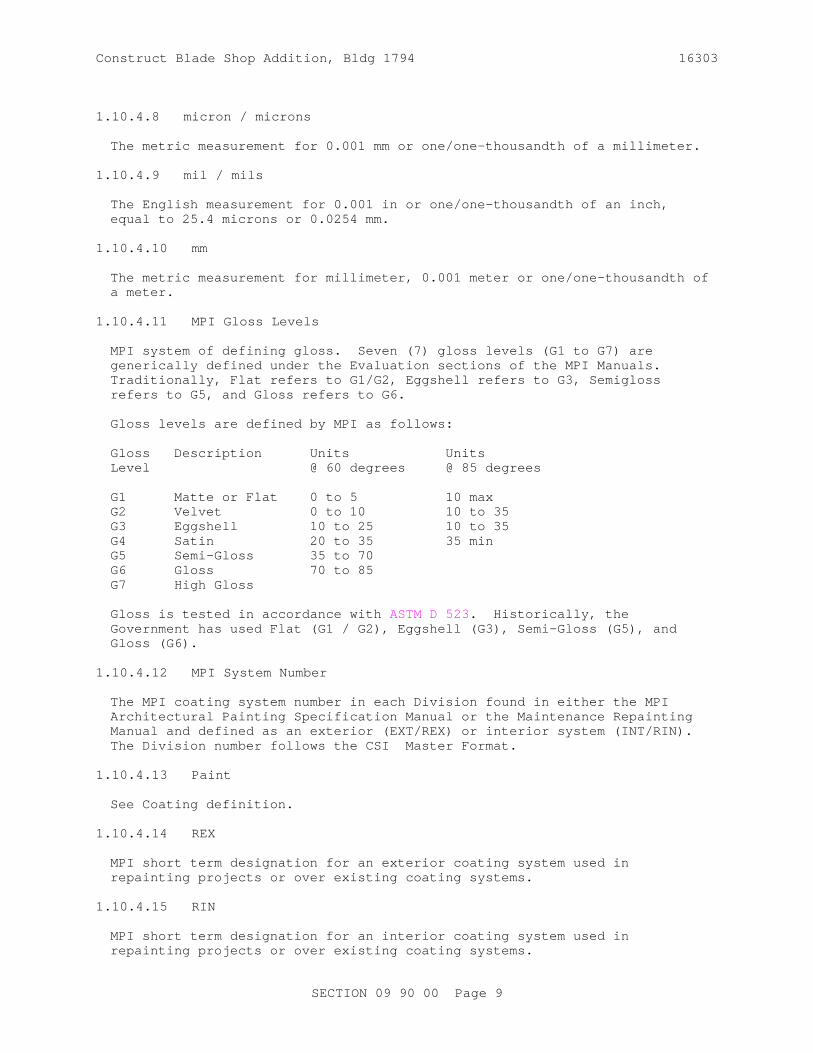
Const r uct Bl ade Shop Addi t i on, Bl dg 1794 16303
1. 10. 4. 8 mi cr on / mi cr ons
The met r i c measur ement f or 0. 001 mm or one/ one- t housandt h of a mi l l i met er .
1. 10. 4. 9 mi l / mi l s
The Engl i sh measur ement f or 0. 001 i n or one/ one- t housandt h of an i nch, equal t o 25. 4 mi cr ons or 0. 0254 mm.
1. 10. 4. 10 mm
The met r i c measur ement f or mi l l i met er , 0. 001 met er or one/ one- t housandt h of a met er .
1. 10. 4. 11 MPI Gl oss Level s
MPI syst em of def i ni ng gl oss. Seven ( 7) gl oss l evel s ( G1 t o G7) ar e gener i cal l y def i ned under t he Eval uat i on sect i ons of t he MPI Manual s. Tr adi t i onal l y, Fl at r ef er s t o G1/ G2, Eggshel l r ef er s t o G3, Semi gl oss r ef er s t o G5, and Gl oss r ef er s t o G6.
Gl oss l evel s ar e def i ned by MPI as f ol l ows:
Gl oss Descr i pt i on Uni t s Uni t sLevel @ 60 degr ees @ 85 degr ees
G1 Mat t e or Fl at 0 t o 5 10 maxG2 Vel vet 0 t o 10 10 t o 35G3 Eggshel l 10 t o 25 10 t o 35G4 Sat i n 20 t o 35 35 mi nG5 Semi - Gl oss 35 t o 70 G6 Gl oss 70 t o 85G7 Hi gh Gl oss
Gl oss i s t est ed i n accor dance wi t h ASTM D 523. Hi st or i cal l y , t he Gover nment has used Fl at ( G1 / G2) , Eggshel l ( G3) , Semi - Gl oss ( G5) , and Gl oss ( G6) .
1. 10. 4. 12 MPI Syst em Number
The MPI coat i ng syst em number i n each Di v i s i on f ound i n ei t her t he MPI Ar chi t ect ur al Pai nt i ng Speci f i cat i on Manual or t he Mai nt enance Repai nt i ng Manual and def i ned as an ext er i or ( EXT/ REX) or i nt er i or syst em ( I NT/ RI N) . The Di v i s i on number f ol l ows t he CSI Mast er For mat .
1. 10. 4. 13 Pai nt
See Coat i ng def i ni t i on.
1. 10. 4. 14 REX
MPI shor t t er m desi gnat i on f or an ext er i or coat i ng syst em used i n r epai nt i ng pr oj ect s or over exi st i ng coat i ng syst ems.
1. 10. 4. 15 RI N
MPI shor t t er m desi gnat i on f or an i nt er i or coat i ng syst em used i n r epai nt i ng pr oj ect s or over exi st i ng coat i ng syst ems.
SECTI ON 09 90 00 Page 9

Const r uct Bl ade Shop Addi t i on, Bl dg 1794 16303
PART 2 PRODUCTS
2. 1 MATERIALS
Conf or m t o t he coating speci f i cat i ons and st andar ds r ef er enced i n PART 3. Submit manuf act ur er ' s t echni cal dat a sheet s f or speci f i ed coatings and sol vent s. Compl y wi t h appl i cabl e r egul at i ons r egar di ng t oxi c and hazar dous materials.
PART 3 EXECUTI ON
3. 1 PROTECTI ON OF AREAS AND SPACES NOT TO BE PAI NTED
Pr i or t o sur f ace pr epar at i on and coat i ng appl i cat i ons, r emove, mask, or ot her wi se pr ot ect , har dwar e, har dwar e accessor i es, machi ned sur f aces, r adi at or cover s, pl at es, l i ght i ng f i x t ur es, publ i c and pr i vat e pr oper t y, and ot her such i t ems not t o be coat ed t hat ar e i n cont act wi t h sur f aces t o be coat ed. Fol l owi ng compl et i on of pai nt i ng, wor kmen ski l l ed i n t he t r ades i nvol ved shal l r ei nst al l r emoved i t ems. Rest or e sur f aces cont ami nat ed by coat i ng mat er i al s, t o or i gi nal condi t i on and r epai r damaged i t ems.
3. 2 SURFACE PREPARATI ON
Remove di r t , spl i nt er s, l oose par t i c l es, gr ease, oi l , di s i nt egr at ed coat i ngs, and ot her f or ei gn mat t er and subst ances del et er i ous t o coat i ng per f or mance as speci f i ed f or each subst r at e bef or e appl i cat i on of pai nt or sur f ace t r eat ment s. Oi l and gr ease shal l be r emoved pr i or t o mechani cal c l eani ng. Cl eani ng shal l be pr ogr ammed so t hat dust and ot her cont ami nant s wi l l not f al l on wet , newl y pai nt ed sur f aces. Exposed f er r ous met al s such as nai l heads on or i n cont act wi t h sur f aces t o be pai nt ed wi t h wat er - t hi nned pai nt s, shal l be spot - pr i med wi t h a sui t abl e cor r osi on- i nhi bi t i ve pr i mer capabl e of pr event i ng f l ash r ust i ng and compat i bl e wi t h t he coat i ng speci f i ed f or t he adj acent ar eas.
3. 2. 1 Addi t i onal Requi r ement s f or Pr epar at i on of Sur f aces Wi t h Exi st i ng Coatings
Bef or e appl i cat i on of coat i ngs, per f or m t he f ol l owi ng on sur f aces cover ed by soundl y- adher ed coat i ngs, def i ned as t hose whi ch cannot be r emoved wi t h a put t y kni f e:
a. Test exi st i ng f i ni shes f or l ead bef or e sandi ng, scr api ng, or r emovi ng. I f l ead i s pr esent , r ef er t o par agr aph Toxi c Mat er i al s.
b. Wi pe pr evi ousl y pai nt ed sur f aces t o r ecei ve sol vent - based coat i ngs, except st ucco and si mi l ar l y r ough sur f aces c l ean wi t h a c l ean, dr y c l ot h sat ur at ed wi t h mi ner al spi r i t s , ASTM D 235. Al l ow sur f ace t o dr y. Wi pi ng shal l i mmedi at el y pr ecede t he appl i cat i on of t he f i r st coat of any coat i ng, unl ess speci f i ed otherwise.
c. Sand exi st i ng gl ossy sur f aces t o be pai nt ed t o r educe gl oss. Br ush, and wi pe c l ean wi t h a damp cl ot h t o r emove dust .
d. The r equi r ement s speci f i ed ar e mi ni mum. Compl y al so wi t h t he appl i cat i on i nst r uct i ons of t he pai nt manuf act ur er .
SECTI ON 09 90 00 Page 10

Const r uct Bl ade Shop Addi t i on, Bl dg 1794 16303
e. Pr evi ousl y pai nt ed sur f aces shal l be t hor oughl y c l eaned of al l gr ease, di r t , dust or ot her f or ei gn mat t er .
f . Bl i s t er i ng, cr acki ng, f l aki ng and peel i ng or ot her det er i or at ed coat i ngs shal l be r emoved.
g. Chal k shal l be r emoved so t hat when t est ed i n accor dance wi t h ASTM D 4214, t he chal k r esi st ance r at i ng i s no l ess t han 8.
h. Sl i ck sur f aces shal l be r oughened. Damaged ar eas such as, but not l i mi t ed t o, nai l hol es, cr acks, chi ps, and spal l s shal l be r epai r ed wi t h sui t abl e mat er i al t o mat ch adj acent undamaged ar eas.
i . Edges of chi pped pai nt shal l be f eat her edged and sanded smoot h.
j . Rust y met al sur f aces shal l be c l eaned as per SSPC r equi r ement s. Sol vent , mechani cal , or chemi cal c l eani ng met hods shal l be used t o pr ovi de sur f aces sui t abl e f or pai nt i ng.
k. New, pr oposed coat i ngs shal l be compat i bl e wi t h exi st i ng coat i ngs.
3. 2. 2 Exi st i ng Coat ed Sur f aces wi t h Mi nor Def ect s
Sand, spackl e, and t r eat mi nor def ect s t o r ender t hem smoot h. Mi nor def ect s ar e def i ned as scr at ches, ni cks, cr acks, gouges, spal l s, al l i gat or i ng, chal k i ng, and i r r egul ar i t i es due t o par t i al peel i ng of pr evi ous coat i ngs. Remove chal k i ng by sandi ng so t hat when t est ed i n accor dance wi t h ASTM D 4214, t he chal k r at i ng i s not l ess t han 8.
3. 2. 3 Removal of Exi st i ng Coat i ngs
Remove exi st i ng coat i ngs f r om t he f ol l owi ng sur f aces:
a. Sur f aces cont ai ni ng l ar ge ar eas of mi nor def ect s;
b. Sur f aces cont ai ni ng mor e t han 20 per cent peel i ng ar ea; and
c. Sur f aces desi gnat ed by t he Cont r act i ng Of f i cer , such as sur f aces wher e r ust shows t hr ough exi st i ng coat i ngs.
3. 2. 4 Subst r at e Repai r
a. Repai r subst r at e sur f ace damaged dur i ng coat i ng r emoval ;
b. Sand edges of adj acent soundl y- adher ed exi st i ng coat i ngs so t hey ar e t aper ed as smoot h as pr act i cal t o ar eas i nvol ved wi t h coat i ng r emoval ; and
c. Cl ean and pr i me t he subst r at e as speci f i ed.
3. 3 PREPARATI ON OF METAL SURFACES
3. 3. 1 Exi st i ng and New Fer r ous Sur f aces
a. Fer r ous Sur f aces i ncl udi ng Shop- coat ed Sur f aces and Smal l Ar eas That Cont ai n Rust , Mi l l Scal e and Ot her For ei gn Subst ances: Sol vent c l ean or det er gent wash i n accor dance wi t h SSPC SP 1 t o r emove oi l and gr ease. Wher e shop coat i s mi ssi ng or damaged, c l ean accor di ng t o SSPC SP 2, SSPC SP 3, , or SSPC SP 10.
SECTI ON 09 90 00 Page 11

Const r uct Bl ade Shop Addi t i on, Bl dg 1794 16303
Br ush- of f bl ast r emai ni ng sur f ace i n accor dance wi t h SSPC SP 7; Shop- coat ed f er r ous sur f aces shal l be pr ot ect ed f r om cor r osi on by t r eat i ng and t ouchi ng up cor r oded ar eas i mmedi at el y upon det ect i on.
b. Sur f aces Wi t h Mor e Than 20 Per cent Rust , Mi l l Scal e, and Ot her For ei gn Subst ances: Cl ean ent i r e sur f ace i n accor dance wi t h SSPC SP 6/ SSPC SP 12 WJ- 3.
3. 3. 2 Fi nal Fer r ous Sur f ace Condi t i on:
For t ool c l eaned sur f aces, t he r equi r ement s ar e st at ed i n SSPC SP 2 and SSPC SP 3. As a v i sual r ef er ence, c l eaned sur f aces shal l be s i mi l ar t o phot ogr aphs i n SSPC VI S 3.
For abr asi ve bl ast c l eaned sur f aces, t he r equi r ement s ar e st at ed i n SSPC SP 7, SSPC SP 6, and SSPC SP 10. As a v i sual r ef er ence, c l eaned sur f aces shal l be s i mi l ar t o phot ogr aphs i n SSPC VI S 1.
For wat er j et c l eaned sur f aces, t he r equi r ement s ar e st at ed i n SSPC SP 12. As a v i sual r ef er ence, c l eaned sur f aces shal l be s i mi l ar t o phot ogr aphs i n SSPC VI S 4.
3. 3. 3 Gal vani zed Sur f aces
a. New or Exi st i ng Gal vani zed Sur f aces Wi t h Onl y Di r t and Zi nc Oxi dat i on Pr oduct s: Cl ean wi t h sol vent , st eam, or non- al kal i ne det er gent sol ut i on i n accor dance wi t h SSPC SP 1. I f t he gal vani zed met al has been passi vat ed or st abi l i zed, t he coat i ng shal l be compl et el y r emoved by br ush- of f abr asi ve bl ast . New gal vani zed st eel t o be coat ed shal l not be " passi vat ed" or " st abi l i zed" I f t he absence of hexaval ent st ai n i nhi bi t or s i s not document ed, t est as descr i bed i n ASTM D 2092, Appendi x X2, and r emove by one of t he met hods descr i bed t her ei n.
3. 3. 4 Non- Fer r ous Met al l i c Sur f aces
Al umi num and al umi num- al l oy, l ead, copper , and ot her nonf er r ous met al surfaces.
a. Sur f ace Cl eani ng: Sol vent c l ean i n accor dance wi t h SSPC SP 1 and wash wi t h mi l d non- al kal i ne det er gent t o r emove di r t and wat er sol ubl e cont ami nant s.
3. 4 PREPARATI ON OF CONCRETE AND CEMENTI TI OUS SURFACE
3. 4. 1 Concr et e and Masonr y
a. Cur i ng: Concr et e, st ucco and masonr y sur f aces shal l be al l owed t o cur e at l east 30 days bef or e pai nt i ng, except concr et e s l ab on gr ade, whi ch shal l be al l owed t o cur e 90 days bef or e pai nt i ng.
b. Sur f ace Cl eani ng: Remove t he f ol l owi ng del et er i ous subst ances.
( 1) Di r t , Gr ease, and Oi l : Wash new and exi st i ng uncoat ed sur f aces wi t h a sol ut i on composed of 1/ 2 cup t r i sodi um phosphat e, 1/ 4 cuphousehol d det er gent , and 4 quar t s of war m wat er . Then r i nse t hor oughl y wi t h f r esh wat er . Wash exi st i ng coat ed sur f aces wi t h a sui t abl e det er gent and r i nse t hor oughl y. For l ar ge ar eas,
SECTI ON 09 90 00 Page 12

Const r uct Bl ade Shop Addi t i on, Bl dg 1794 16303
wat er bl ast i ng may be used.
( 2) Fungus and Mol d: Wash , exi st i ng coat ed, sur f aces wi t h a sol ut i on composed of 1/ 2 cup t r i sodi um phosphat e, 1/ 4 cup househol d det er gent , 1 quar t 5 per cent sodi um hypochl or i t e sol ut i on and 3 quar t s of war m wat er . Ri nse t hor oughl y wi t h f r esh water.
( 3) Pai nt and Loose Par t i c l es: Remove by wi r e br ushi ng.
( 4) Ef f l or escence: Remove by scr api ng or wi r e br ushi ng f ol l owed by washi ng wi t h a 5 t o 10 per cent by wei ght aqueous sol ut i on of hydr ochl or i c ( mur i at i c) aci d. Do not al l ow aci d t o r emai n on t he sur f ace f or mor e t han f i ve mi nut es bef or e r i nsi ng wi t h f r esh wat er . Do not aci d c l ean mor e t han 4 squar e f eet of sur f ace, per wor kman, at one t i me.
c. Cosmet i c Repai r of Mi nor Def ect s: Repai r or f i l l mor t ar j oi nt s and mi nor def ect s, i ncl udi ng but not l i mi t ed t o spal l s, i n accor dance wi t h manuf act ur er ' s r ecommendat i ons and pr i or t o coat i ng appl i cat i on.
d. Al l owabl e Moi st ur e Cont ent : Lat ex coat i ngs may be appl i ed t o damp sur f aces, but not t o sur f aces wi t h dr opl et s of wat er . Do not appl y epoxi es t o damp ver t i cal sur f aces as det er mi ned by ASTM D 4263 or hor i zont al sur f aces t hat exceed 3 l bs of moi st ur e per 1000 squar e f eet i n 24 hour s as det er mi ned by ASTM F 1869. I n al l cases f ol l ow manuf act ur er s r ecommendat i ons. Al l ow sur f aces t o cur e a mi ni mum of 30 days bef or e pai nt i ng.
3. 4. 2 Gypsum Boar d, Pl ast er , and St ucco
a. Sur f ace Cl eani ng: Pl ast er and st ucco shal l be c l ean and f r ee f r om l oose mat t er ; gypsum boar d shal l be dr y. Remove l oose di r t and dust by br ushi ng wi t h a sof t br ush, r ubbi ng wi t h a dr y c l ot h, or vacuum- cl eani ng pr i or t o appl i cat i on of t he f i r st coat mat er i al . A damp cl ot h or sponge may be used i f pai nt wi l l be wat er - based.
b. Repai r of Mi nor Def ect s: Pr i or t o pai nt i ng, r epai r j oi nt s, cr acks, hol es, sur f ace i r r egul ar i t i es, and ot her mi nor def ect s wi t h pat chi ng pl ast er or spackl i ng compound and sand smoot h.
c. Al l owabl e Moi st ur e Cont ent : Lat ex coat i ngs may be appl i ed t o damp sur f aces, but not sur f aces wi t h dr opl et s of wat er . Do not appl y epoxi es t o damp sur f aces as det er mi ned by ASTM D 4263. New pl ast er t o be coat ed shal l have a maxi mum moi st ur e cont ent of 8 per cent , when measur ed i n accor dance wi t h ASTM D 4444, Met hod A, unl ess ot her wi se aut hor i zed. I n addi t i on t o moi st ur e cont ent r equi r ement s, al l ow new pl ast er t o age a mi ni mum of 30 days bef or e pr epar at i on f or pai nt i ng.
3. 5 APPLI CATI ON3. 5. 1 Coat i ng Appl i cat i on
Pai nt i ng pr act i ces shal l compl y wi t h appl i cabl e f eder al , st at e and l ocal l aws enact ed t o i nsur e compl i ance wi t h Feder al Cl ean Ai r St andar ds. Appl y coat i ng mat er i al s i n accor dance wi t h SSPC PA 1. SSPC PA 1 met hods ar e
SECTI ON 09 90 00 Page 13

Const r uct Bl ade Shop Addi t i on, Bl dg 1794 16303
appl i cabl e t o al l subst r at es, except as modi f i ed her ei n.
At t he t i me of appl i cat i on, pai nt shal l show no si gns of det er i or at i on. Uni f or m suspensi on of pi gment s shal l be mai nt ai ned dur i ng appl i cat i on.
Unl ess ot her wi se speci f i ed or r ecommended by t he pai nt manuf act ur er , pai nt may be appl i ed by br ush, r ol l er , or spr ay. Use t r i gger oper at ed spr ay nozzl es f or wat er hoses. Rol l er s f or appl y i ng pai nt s and enamel s shal l be of a t ype desi gned f or t he coat i ng t o be appl i ed and t he sur f ace t o be coat ed. Wear pr ot ect i ve c l ot hi ng and r espi r at or s when appl y i ng oi l - based pai nt s or usi ng spr ay equi pment wi t h any pai nt s.
Pai nt s, except wat er - t hi nned t ypes, shal l be appl i ed onl y t o sur f aces t hat ar e compl et el y f r ee of moi st ur e as det er mi ned by s i ght or t ouch.
Thor oughl y wor k coat i ng mat er i al s i nt o j oi nt s, cr evi ces, and open spaces. Speci al at t ent i on shal l be gi ven t o i nsur e t hat al l edges, cor ner s, cr evi ces, wel ds, and r i vet s r ecei ve a f i l m t hi ckness equal t o t hat of adj acent pai nt ed sur f aces.
Each coat of pai nt shal l be appl i ed so dr y f i l m shal l be of uni f or m t hi ckness and f r ee f r om r uns, dr ops, r i dges, waves, pi nhol es or ot her voi ds, l aps, br ush mar ks, and var i at i ons i n col or , t ext ur e, and f i ni sh. Hi di ng shal l be compl et e.
Touch up damaged coat i ngs bef or e appl y i ng subsequent coat s. I nt er i or ar eas shal l be br oom cl ean and dust f r ee bef or e and dur i ng t he appl i cat i on of coat i ng mat er i al .Appl y pai nt t o new f i r e ext i ngui shi ng spr i nkl er syst ems i ncl udi ng val ves, pi pi ng, condui t , hanger s, suppor t s, mi scel l aneous met al wor k, and accessor i es. Shi el d spr i nkl er heads wi t h pr ot ect i ve cover i ngs whi l e pai nt i ng i s i n pr ogr ess. Remove spr i nkl er heads whi ch have been pai nt ed and r epl ace wi t h new spr i nkl er heads. For pi pi ng i n unf i ni shed spaces, pr ovi de pr i med sur f aces wi t h one coat of r ed al kyd gl oss enamel t o a mi ni mum dr y f i l m t hi ckness of 1. 0 mi l . Unf i ni shed spaces i ncl ude at t i c spaces, spaces above suspended cei l i ngs, cr awl spaces, pi pe chases, mechani cal equi pment r oom, and space wher e wal l s or cei l i ng ar e not pai nt ed or not const r uct ed of a pr ef i ni shed mat er i al . For pi pi ng i n f i ni shed ar eas, pr ovi de pr i me sur f aces wi t h t wo coat s of pai nt t o mat ch adj acent sur f aces, except pr ovi de val ves and oper at i ng accessor i es wi t h one coat of r ed al kyd gl oss enamel . Upon compl et i on of pai nt i ng, r emove pr ot ect i ve cover i ng f r om spr i nkl er heads.
a. Dr yi ng Ti me: Al l ow t i me bet ween coat s, as r ecommended by t he coat i ng manuf act ur er , t o per mi t t hor ough dr yi ng, but not t o pr esent t opcoat adhesi on pr obl ems. Pr ovi de each coat i n speci f i ed condi t i on t o r ecei ve next coat .
b. Pr i mer s, and I nt er medi at e Coat s: Do not al l ow pr i mer s or i nt er medi at e coat s t o dr y mor e t han 30 days, or l onger t han r ecommended by manuf act ur er , bef or e appl y i ng subsequent coat s. Fol l ow manuf act ur er ' s r ecommendat i ons f or sur f ace pr epar at i on i f pr i mer s or i nt er medi at e coat s ar e al l owed t o dr y l onger t han r ecommended by manuf act ur er s of subsequent coat i ngs. Each coat shal l cover sur f ace of pr ecedi ng coat or sur f ace compl et el y, and t her e shal l be a v i sual l y per cept i bl e di f f er ence i n shades of successi ve coat s.
c. Fi ni shed Sur f aces: Pr ovi de f i ni shed sur f aces f r ee f r om r uns, dr ops, r i dges, waves, l aps, br ush mar ks, and var i at i ons i n col or s.
SECTI ON 09 90 00 Page 14

Const r uct Bl ade Shop Addi t i on, Bl dg 1794 16303
d. Ther moset t i ng Pai nt s: Topcoat s over t her moset t i ng pai nt s ( epoxi es and ur et hanes) shoul d be appl i ed wi t hi n t he over coat i ng wi ndow r ecommended by t he manuf act ur er .
3. 5. 2 Mixing and Thi nni ng of Pai nt s
Reduce pai nt s t o pr oper consi st ency by addi ng f r esh pai nt , except when t hi nni ng i s mandat or y t o sui t sur f ace, t emper at ur e, weat her condi t i ons, appl i cat i on met hods, or f or t he t ype of pai nt bei ng used. Obt ai n wr i t t en per mi ssi on f r om t he Cont r act i ng Of f i cer t o use t hi nner s. The wr i t t en per mi ssi on shal l i ncl ude quant i t i es and t ypes of t hi nner s t o use.
When t hi nni ng i s al l owed, pai nt s shal l be t hi nned i mmedi at el y pr i or t o appl i cat i on wi t h not mor e t han quani t y r ecommended by pai nt manuf act ur er of sui t abl e t hi nner per gal l on. The use of t hi nner shal l not r el i eve t he Cont r act or f r om obt ai ni ng compl et e hi di ng, f ul l f i l m t hi ckness, or r equi r ed gl oss. Thi nni ng shal l not cause t he pai nt t o exceed l i mi t s on vol at i l e or gani c compounds. Pai nt s of di f f er ent manuf act ur er s shal l not be mi xed.
3. 5. 3 Two- Component Syst ems
Two- component syst ems shal l be mi xed i n accor dance wi t h manuf act ur er ' s i nst r uct i ons. Any t hi nni ng of t he f i r st coat t o ensur e pr oper penet r at i on and seal i ng shal l be as r ecommended by t he manuf act ur er f or each t ype of substrate.
3. 5. 4 Coat i ng Syst ems
a. Syst ems by Subst r at es: Appl y coat i ngs t hat conf or m t o t he r espect i ve speci f i cat i ons l i s t ed i n t he f ol l owi ng Tabl es:
Table Di v i s i on 5. Ext er i or Met al , Fer r ous and Non- Fer r ous Pai nt Tabl e Di v i s i on 3. I nt er i or Concr et e Pai nt Tabl e Di v i s i on 4. I nt er i or Concr et e Masonr y Uni t s Pai nt Tabl e Di v i s i on 5. I nt er i or Met al , Fer r ous and Non- Fer r ous Pai nt Tabl e Di v i s i on 9: I nt er i or Pl ast er , Gypsum Boar d, Text ur ed Sur f aces Pai nt Tabl e
b. Mi ni mum Dr y Fi l m Thi ckness ( DFT) : Appl y pai nt s, pr i mer s, var ni shes, enamel s, under coat s, and ot her coat i ngs t o a mi ni mum dr y f i l m t hi ckness of 1. 5 mi l each coat unl ess speci f i ed ot her wi se i n t he Tabl es. Coat i ng t hi ckness wher e speci f i ed, r ef er s t o t he mi ni mum dr y f i l m t hi ckness.
c. Coat i ngs f or Sur f aces Not Speci f i ed Ot her wi se: Coat sur f aces whi ch have not been speci f i ed, t he same as sur f aces havi ng s i mi l ar condi t i ons of exposur e.
d. Exi st i ng Sur f aces Damaged Dur i ng Per f or mance of t he Wor k, I ncl udi ng New Pat ches I n Exi st i ng Sur f aces: Coat sur f aces wi t h t he f ol l owi ng:
( 1) One coat of pr i mer .
( 2) One coat of under coat or i nt er medi at e coat .
SECTI ON 09 90 00 Page 15
Const r uct Bl ade Shop Addi t i on, Bl dg 1794 16303
( 3) One t opcoat t o mat ch adj acent sur f aces.
e. Exi st i ng Coat ed Sur f aces To Be Pai nt ed: Appl y coat i ngs conf or mi ng t o t he r espect i ve speci f i cat i ons l i s t ed i n t he Tabl es her ei n, except t hat pr et r eat ment s, seal er s and f i l l er s need not be pr ovi ded on sur f aces wher e exi st i ng coat i ngs ar e soundl y adher ed and i n good condi t i on. Do not omi t under coat s or pr i mer s.
3. 6 COATI NG SYSTEMS FOR METAL
Appl y coat i ngs of Tabl es i n Di v i s i on 5 f or Ext er i or and I nt er i or .
a. Appl y speci f i ed f er r ous met al pr i mer on t he same day t hat sur f ace i s c l eaned, t o sur f aces t hat meet al l speci f i ed sur f ace pr epar at i on r equi r ement s at t i me of appl i cat i on.
b. I naccessi bl e Sur f aces: Pr i or t o er ect i on, use one coat of speci f i ed pr i mer on met al sur f aces t hat wi l l be i naccessi bl e af t er erection.
c. Shop- pr i med Sur f aces: Touch up exposed subst r at es and damaged coat i ngs t o pr ot ect f r om r ust i ng pr i or t o appl y i ng f i el d pr i mer .
3. 7 COATI NG SYSTEMS FOR CONCRETE AND CEMENTI TI OUS SUBSTRATES
Appl y coat i ngs of Tabl es i n Di v i s i on 3, 4 and 9 f or Ext er i or and I nt er i or .
3. 8 PI PI NG I DENTI FI CATI ON
Pi pi ng I dent i f i cat i on, I ncl udi ng Sur f aces I n Conceal ed Spaces: Pr ovi de i n accor dance wi t h ASME A13. 1. Pl ace st enci l i ng i n c l ear l y v i s i bl e l ocat i ons. On pi pi ng not cover ed by ASME A13. 1, stencil appr oved names or code l et t er s, i n l et t er s a mi ni mum of 1/ 2 i nch hi gh f or pi pi ng and a mi ni mum of 2 i nches hi gh el sewher e. St enci l ar r ow- shaped mar ki ngs on pi pi ng t o i ndi cat e di r ect i on of f l ow usi ng bl ack st enci l pai nt . 3. 9
I NSPECTI ON AND ACCEPTANCE
I n addi t i on t o meet i ng pr evi ousl y speci f i ed r equi r ement s, demonst r at e mobi l i t y of movi ng component s, i ncl udi ng swi ngi ng and sl i di ng door s, cabi net s, and wi ndows wi t h oper abl e sash, f or i nspect i on by t he Cont r act i ng Of f i cer . Per f or m t hi s demonst r at i on af t er appr opr i at e cur i ng and dr yi ng t i mes of coat i ngs have el apsed and pr i or t o i nvoi c i ng f or f i nal payment .
3. 10 PAI NT TABLES
3. 10. 1 EXTERI OR PAI NT TABLES
DI VI SI ON 5: EXTERI OR METAL, FERROUS AND NON- FERROUS PAI NT TABLE
STEEL / FERROUS SURFACES
A. Exi st i ng st eel t hat has been spot - bl ast ed t o SSPC SP 6:
1. Sur f ace pr evi ousl y coat ed wi t h al kyd or l at ex:
Wat er bor ne Li ght I ndust r i al Coat i ng MPI REX 5. 1C- G5 ( Semi gl oss)
SECTI ON 09 90 00 Page 16

Const r uct Bl ade Shop Addi t i on, Bl dg 1794 16303
STEEL / FERROUS SURFACES Spot Pr i mer : I nt er medi at e: Topcoat : MPI 79 MPI 163 MPI 163 Syst em DFT: 5 mi l s
2. MPI REX 5. 1L- G6 ( Gl oss) Spot Pr i mer : I nt er medi at e: Topcoat : MPI 101 MPI 164 MPI 164 Syst em DFT: 5 mi l s
B. Gal vani zed sur f aces wi t h s l i ght coat i ng det er i or at i on; l i t t l e or no r ust i ng:
1. Wat er bor ne Li ght I ndust r i al Coat i ng MPI REX 5. 3J- G5 ( Semi gl oss) Pr i mer : I nt er medi at e: Topcoat : MPI 134 N/ A MPI 163 Syst em DFT: 4. 5 mi l s
3. 10. 2 I NTERI OR PAI NT TABLES
DI VI SI ON 3: I NTERI OR CONCRETE PAI NT TABLE
A. New and uncoat ed exi st i ng and Exi st i ng, pr evi ousl y pai nt ed Concr et e, ver t i cal sur f aces, not speci f i ed ot her wi se:
1. New; MPI I NT 3. 1C- G5 ( Semi gl oss) / Exi st i ng; MPI RI N 3. 1J- G5 ( Semi gl oss) Pr i mer : I nt er medi at e: Topcoat : MPI 50 MPI 141 MPI 141 Syst em DFT: 4 mi l s
B. New and uncoat ed exi st i ng and Exi st i ng, pr evi ousl y pai nt ed Concr et e i n t oi l et s not ot her wi se speci f i ed except f l oor s:
1. New; MPI I NT 3. 1L- G6( Gl oss) / Exi st i ng; MPI RI N 3. 1C- G6( Gl oss) Pr i mer : I nt er medi at e: Topcoat : MPI 154 MPI 154 MPI 154 Syst em DFT: 4. 8 mi l s
C. New and uncoat ed exi st i ng and Exi st i ng, pr evi ousl y pai nt ed concr et e f l oor s i n f ol l owi ng ar eas Wor k Bay 101, Wor k Bay 102, Jani t or 103, and Wor k Bay 105:
1. Epoxy New; MPI I NT 3. 2C- G6 ( Gl oss) / Exi st i ng; MPI RI N 3. 2C- G6 ( Gl oss) Pr i mer : I nt er medi at e: Topcoat : MPI 77 MPI 77 MPI 77 Syst em DFT: 5 mi l s
Not e: Pr i mer may be r educed f or penet r at i on per manuf act ur er ' s i nst r uct i ons.
DI VI SI ON 4: I NTERI OR CONCRETE MASONRY UNI TS PAI NT TABLE
A. Exi st i ng, pr evi ousl y pai nt ed Concr et e masonr y:
1. Exi st i ng; MPI RI N 4. 2L- G5 ( Semi gl oss)
SECTI ON 09 90 00 Page 17

Const r uct Bl ade Shop Addi t i on, Bl dg 1794 16303
DI VI SI ON 4: I NTERI OR CONCRETE MASONRY UNI TS PAI NT TABLE Spot Pr i mer : I nt er medi at e: Topcoat : MPI 50 MPI 147 MPI 147 Syst em DFT: 4 mi l s B. Exi st i ng, pr evi ousl y pai nt ed, concr et e masonr y uni t s i n t oi l et s, and ot her hi gh humi di t y ar eas unl ess ot her wi se speci f i ed:
1. MPI RI N 4. 2G- G5( Semi gl oss) Spot Pr i mer : I nt er medi at e: Topcoat : MPI 153 MPI 153 MPI 153 Syst em DFT: 4. 5 mi l s
DI VI SI ON 5: I NTERI OR METAL, FERROUS AND NON- FERROUS PAI NT TABLE
I NTERI OR STEEL / FERROUS SURFACES
A. Met al , Mechani cal , El ect r i cal , Fi r e ext i ngui shi ng spr i nkl er syst ems i ncl udi ng val ves, condui t , hanger s, suppor t s, Sur f aces adj acent t o pai nt ed sur f aces ( Mat ch sur r oundi ng f i ni sh) , exposed copper pi pi ng, and mi scel l aneous met al i t ems not ot her wi se speci f i ed except f l oor s, hot met al sur f aces, and new pr ef i ni shed equi pment :
1. Hi gh Per f or mance Ar chi t ect ur al Lat ex MPI I NT 5. 1R- G5 ( Semi gl oss) Pr i mer : I nt er medi at e: Topcoat : MPI 79 MPI 141 MPI 141 Syst em DFT: 5 mi l s
2. MPI I NT 5. 1E- G6 ( Gl oss) Pr i mer : I nt er medi at e: Topcoat : MPI 79 MPI 48 MPI 48 Syst em DFT: 5. 25 mi l s
B. Met al i n t oi l et s, r est r ooms, not ot her wi se speci f i ed except f l oor s, hot met al sur f aces, and new pr ef i ni shed equi pment :
1. Al kyd MPI I NT 5. 1E- G5 ( Semi gl oss) Pr i mer : I nt er medi at e: Topcoat : MPI 79 MPI 47 MPI 47 Syst em DFT: 5. 25 mi l s
C. Mi scel l aneous non- f er r ous met al i t ems not ot her wi se speci f i ed except f l oor s, hot met al sur f aces, and new pr ef i ni shed equi pment . Mat ch sur r oundi ng f i ni sh:
1. Hi gh Per f or mance Ar chi t ect ur al Lat ex MPI I NT 5. 4F- G5 ( Semi gl oss) Pr i mer : I nt er medi at e: Topcoat : MPI 95 MPI 141 MPI 141 Syst em DFT: 5 mi l s
DI VI SI ON 9: I NTERI OR PLASTER, GYPSUM BOARD, TEXTURED SURFACES PAI NT TABLE
A. New and Exi st i ng, pr evi ousl y pai nt ed Plaster and Wal l boar d not otherwise specified:
SECTI ON 09 90 00 Page 18

Const r uct Bl ade Shop Addi t i on, Bl dg 1794 16303
DI VI SI ON 9: I NTERI OR PLASTER, GYPSUM BOARD, TEXTURED SURFACES PAI NT TABLE
1. Lat ex New; MPI I NT 9. 2B- G5 ( Semi gl oss) / Exi st i ng; MPI RI N 9. 2B- G5 ( Semi gl oss) Pr i mer : I nt er medi at e: Topcoat : MPI 50 MPI 141 MPI 141 Syst em DFT: 4 mi l s
B. New and Exi st i ng, pr evi ousl y pai nt ed Wal l boar d i n, r est r ooms, shower ar eas:
1. Wat er bor ne Li ght I ndust r i al Coat i ng New; MPI I NT 9. 2L- G5( Semi gl oss) / Exi st i ng; MPI RI N 9. 2L- G5 ( Semi gl oss) Pr i mer : I nt er medi at e: Topcoat : MPI 50 MPI 153 MPI 153 Syst em DFT: 4 mi l s
- - End of Sect i on - -
SECTI ON 09 90 00 Page 19