important note - adams elevator max installation... · safety light curtain for elevator door...
TRANSCRIPT

1-800-323-0796 USA 1-800-268-5392 Canada
Part No. 103 207 Rel. 2005-05-16
Safety Light Curtain for Elevator Door Protection
GateKeeper MAXTM
®
C US
manufactured under ISO 9001: 2000
IMPORTANT NOTE
FOLLOW THE INSTRUCTIONS GIVEN IN THIS MANUAL CAREFULLY. FAILURE TO DO SO MAY CAUSE CUSTOMER COMPLAINTSAND SERIOUS
CALL BACKS. KEEP INSTRUCTION MANUAL ON SITE.
Installation and Operation Manual
GateKeeper MAXTM – Safety is our priority!
GateKeepe MaxTM is a safety device for elevator doors using up to 154 light beams and is the optimal solution when
a dense protection field is needed at the most cost effective price.
GateKeeper MAXTM Installation and Operation Manual
2 A850G7MAX-INS 1-800-323-0796 1-800-268-5392
IMPORTANT NOTICE WHEN THE GATEKEEPER MAXTM LIGHT CURTAIN IS USED AS A REPLACEMENT FOR MECHANICAL SAFETY EDGES, IT IS THE RESPONSIBILITY OF THE INSTALLER TO ENSURE THAT ON COMPLETION, THE INSTALLATION COMPLIES WITH ALL THE RELEVANT STATE CODES, LOCAL CODES AND REGULATIONS THAT PERTAIN TO INFRARED AND PHOTOELECTRIC DOOR PROTECTION DEVICES. IN CANADA, PARTICULAR ATTENTION SHOULD BE GIVEN TO CLAUSES 2.13.5.1 AND 2.13.5.2 CAN/CSA-B44-B89. GATEKEEPER MUST BE INSTALLED ONLY BY AUTHORIZED AND FULLY TRAINED PERSONNEL. PLEASE TAKE NOTE THAT OBJECTS THINNER THAN THE SENSOR SPACING MAY NOT BE DETECTED.
DO NOT USE THIS PRODUCT FOR THE PROTECTION OF DANGEROUS MACHINERY OR IN EXPLOSIVE ATMOSPHERES OR RADIOACTIVE ENVIRONMENTS. USE ONLY SPECIFIC AND APPROVED TYPES OF SAFETY DEVICES FOR SUCH APPLICATIONS. OTHERWISE SERIOUS INJURY OR DEATH MAY OCCUR.
Ex
WHEN SUPPLY VOLTAGES GREATER THAN 42 VOLTS ARE USED, THE INTERFACE WIRING TO THE POWER SUPPLY AND TO THE DOOR DRIVE MUST BE MADE THROUGH A GREENFIELD FITTING.
Installation and Operation Manual GateKeeper MAXTM
1-800-323-0796 www.adamselevator.com 3 1-800-268-5392
Content 1. Operation ................................................ 3 2. Applications ............................................. 4 3. Fail Safe Operation.................................. 4 4. Automatic Power Supply Adaption .......... 4 5. Installation............................................... 4
5.1. Installation Emitter / Receiver.......................5 5.1.1. Center Opening Doors........................5 5.1.2. Side Opening Door .............................6
5.2. Cable Guidance .........................................6 5.3. Installation of the control unit ......................7 5.4. Electrical Installation....................................8
5.4.1. Power supply.......................................8 5.4.2. Emitter................................................8 5.4.3. Receiver..............................................8 5.4.4. Fire recall ...........................................8 5.4.5. Light curtain relay................................8 5.4.6. Nudging and Nuding-AUX relay ..........8
5.5. Power-up and test .....................................10 5.6. Snap on the vison shield............................10 5.7. Finished ...................................................11 5.8. Maintenance.............................................11 5.9. Disposal ...................................................11
6. Trouble shooting.................................... 12 7. Technical Data ....................................... 13
7.1. Specifications............................................13 7.2. Certificate of Compliance No. 1049058 ....13 7.3. Dimensions ..............................................14
7.3.1. Emitter / Receiver ..............................14 7.3.2. Control unit with housing...................14
7.4. List of part numbers ..................................16 7.4.1. Complete units and accessories .........16 7.4.2. Spare parts .......................................16 7.4.3. Bill of materials of complete units.......16
1. Operation
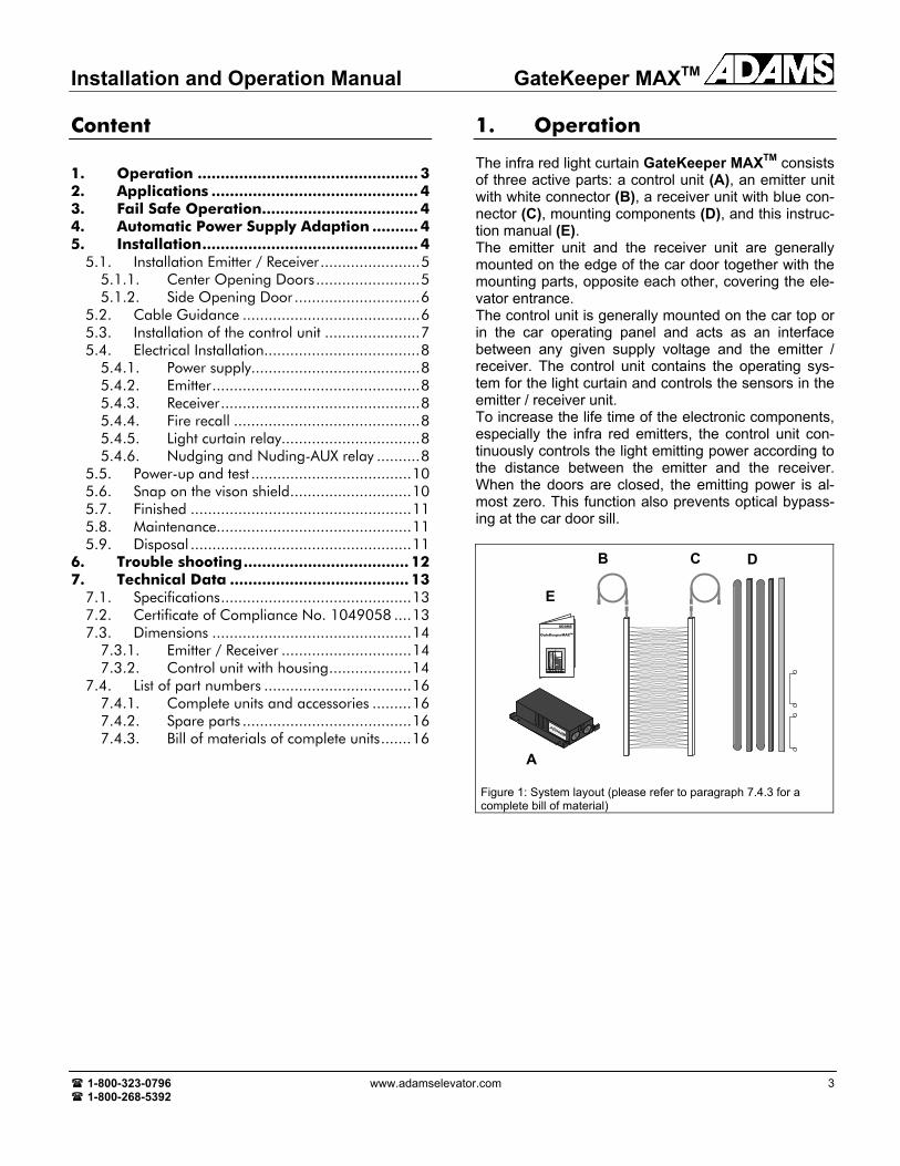
The infra red light curtain GateKeeper MAXTM consists of three active parts: a control unit (A), an emitter unit with white connector (B), a receiver unit with blue con-nector (C), mounting components (D), and this instruc-tion manual (E). The emitter unit and the receiver unit are generally mounted on the edge of the car door together with the mounting parts, opposite each other, covering the ele-vator entrance. The control unit is generally mounted on the car top or in the car operating panel and acts as an interface between any given supply voltage and the emitter / receiver. The control unit contains the operating sys-tem for the light curtain and controls the sensors in the emitter / receiver unit. To increase the life time of the electronic components, especially the infra red emitters, the control unit con-tinuously controls the light emitting power according to the distance between the emitter and the receiver. When the doors are closed, the emitting power is al-most zero. This function also prevents optical bypass-ing at the car door sill.
ADAMS
GateKeeperMAXTM
Figure 1: System layout (please refer to paragraph 7.4.3 for a complete bill of material)
A
E
B C D

GateKeeper MAXTM Installation and Operation Manual
4 A850G7MAX-INS 1-800-323-0796 1-800-268-5392
2. Applications
The mounting parts are configured so that they may be used for side opening doors as well as for center opening doors. The whole kit can be used for new installations as well as for modernization of existing elevators. Please refer to the appropriate kit type.
Figure 2: Center opening door Figure 3: Side opening door
3. Fail Safe Operation1
If power to the system is lost, the output relay is de-energized resulting in re-opening of the elevator doors. Please note that a door drive with the nudging feature may override the output relay of the light curtain and force the doors to close. The proper operation of the microprocessor is pro-tected by a watch-dog circuit which restarts the pro-gram if the processor fails to execute the normal pro-gram sequence. In such a case the output relay will de-energized immediately and provide a door open signal.
1 This device (as well as all other door protection systems on the market) cannot – by its nature – provide absolute safety for elevator passengers passing through the doorway. It must not be used as the final fail safe device of the door mechanism. This ultimate safety function must be provided by a fail safe force and kinetic energy limiter. 1 Due to the nature of door system designs, (which as complete systems are not fail safe), in extremely rare conditions doors can close even with an obstacle present. Therefore, there must be, by code, other safety means to prevent passengers from being hurt by the elevator doors. These dangerous situations should and can be detected by the elevator control, which should, in such a case, take the elevator out of service. Final safety responsibility remains with the system intergrator.
4. Automatic Power Supply Adaption
The control unit contains state-of-the-art-technology to operate with any available supply voltage without any adjustments or special wiring. Any voltage from 17 Volts to 265 Volts AC or DC can be used and the light curtain will operate properly. If DC voltage is used the polarity to the terminals P and N is irrelevant. This fea-ture is very useful, especially for modernization, where the supply voltage on the car top may not be precisely known.
5. Installation
Installation should be done in the following sequence: 1. The first step of installation is to open the shipping
box and verify that the components are all there ac-cording to the bill of material (refer to page 16)
2. Use proper barricading and displaying to prevent public entry into the work area
3. Install the emitter / receiver with the mounting- or spacer profile to the door wings or to the slam post
4. Guide the cables of the emitter/receiver to the con-trol unit using the cable protection tube (if provided in the mounting kit) and cable ties and install the cable guide to prevent possible cable swing
5. Install the control unit 6. Electrical installation 7. Power-up and test 8. Snap on the vision shields to cover the emitter /
receiver and install the cover to the control unit

Installation and Operation Manual GateKeeper MAXTM
1-800-323-0796 www.adamselevator.com 5 1-800-268-5392
The following picture shows an overview of the installation. Details are described more in detail in the following sec-tions.
13 ... 75 (1/2" ... 3")
6 (1
/4")
Light curtain
Spacer / mounting profile
Control unit#10x1/2" self-drilling / self-tapping
Cable guide#10x1/2" self-drilling / self-tapping
Vision shield
Figure 4: Mounting overview
5.1. Installation Emitter / Receiver
Installation procedure is as follows: 1. Install the spacer profile to the door with 6 self tap-
ping screws (note the 'bottom'-label on the mount-ing / spacer profile and refer to Fig. 4 for proper mounting position).
2. Install the sensor unit to the spacer profile with 3 sink screws.
3. Install the opposite unit on the strike jamb or other door so that the alignment is as true as possible when the door is fully closed.
5.1.1. Center Opening Doors
The spacer profiles are mounted to the car door wings with 6 #10 x ½" self drilling / self tapping screws. The spacer profile has a label which indicates the bottom side. The emitter and the receiver edge must then be installed with 3 #6 x 1" sink screws using the pre-drilled holes on the spacer profiles.
Important It is important that the active sensor sides of the emitter / receiver units are looking "face-to-face". The active sensor sides are recognizable by the round black plastic lenses.
Important The recommended distance betweenthe door sill and the bottom of thesensors (mounting profile and spacerprofile respectively) is ¼". A greaterdistance reduces safety due to anunprotected area right above the sill!
GateKeeper MAXTM Installation and Operation Manual
6 A850G7MAX-INS 1-800-323-0796 1-800-268-5392
Spacer profile
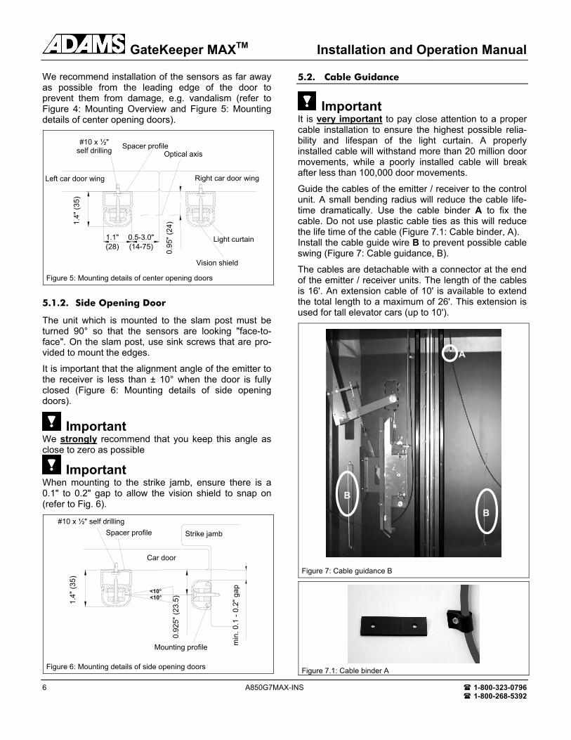
We recommend installation of the sensors as far away as possible from the leading edge of the door to prevent them from damage, e.g. vandalism (refer to Figure 4: Mounting Overview and Figure 5: Mounting details of center opening doors).
Figure 5: Mounting details of center opening doors
5.1.2. Side Opening Door
The unit which is mounted to the slam post must be turned 90° so that the sensors are looking "face-to-face". On the slam post, use sink screws that are pro-vided to mount the edges.
It is important that the alignment angle of the emitter to the receiver is less than ± 10° when the door is fully closed (Figure 6: Mounting details of side opening doors).
Important We strongly recommend that you keep this angle as close to zero as possible
Important When mounting to the strike jamb, ensure there is a 0.1" to 0.2" gap to allow the vision shield to snap on (refer to Fig. 6).
Figure 6: Mounting details of side opening doors
5.2. Cable Guidance
Important It is very important to pay close attention to a proper cable installation to ensure the highest possible relia-bility and lifespan of the light curtain. A properly installed cable will withstand more than 20 million door movements, while a poorly installed cable will break after less than 100,000 door movements.
Guide the cables of the emitter / receiver to the control unit. A small bending radius will reduce the cable life-time dramatically. Use the cable binder A to fix the cable. Do not use plastic cable ties as this will reduce the life time of the cable (Figure 7.1: Cable binder, A). Install the cable guide wire B to prevent possible cable swing (Figure 7: Cable guidance, B).
The cables are detachable with a connector at the end of the emitter / receiver units. The length of the cables is 16'. An extension cable of 10' is available to extend the total length to a maximum of 26'. This extension is used for tall elevator cars (up to 10').
Figure 7: Cable guidance B
Figure 7.1: Cable binder A
Spacer profile #10 x ½" self drilling
1.4"
(35)
0.92
5" (2
3.5)
Mounting profile
Strike jamb
min
. 0.1
- 0.
2" g
ap
<10°
Car door
<10°
Vision shield
Light curtain
Left car door wing Right car door wing
#10 x ½" self drilling Spacer profile
Optical axis
1.1" (28)
0.5-3.0" (14-75)
0.95
" (24
) 1.4"
(35)
B
A
B

Installation and Operation Manual GateKeeper MAXTM
1-800-323-0796 www.adamselevator.com 7 1-800-268-5392
5.3. Installation of the control unit
The control unit can be mounted horizontally or verti-cally using #10 x ½" self drilling / self tapping screws. An ideal mounting position is drawn in Figure 4.
Figure 8: GateKeeper MAXTM Control unit
NOTICE:
The PCB is sensitive to electro static discharge and must be handled with care to prevent call backs. Use anti-static procedures when handling these boards.
When the supply voltage or the voltage at the relay terminal is below 42 volts, use the standard cable entrance gas-kets to connect the emitter, the receiver, the relay and power.
Connect all wiring with more than 42 V through a Greenfield Fitting.
Disconnect power before opening the control unit to prevent electrical shock.
Do not remove inside cover or fuse cap.
Figure 9: Final installation with Greenfield Fitting (from T&B or other UL / CSA approved manufacturer)
GateKeeper MAXTM Installation and Operation Manual
8 A850G7MAX-INS 1-800-323-0796 1-800-268-5392
5.4. Electrical Installation
5.4.1. Power supply
N : AC neutral, plus or minus for DC P : AC Hot, plus or minus for DC : Protective ground
5.4.2. Emitter
The white emitter connector must be plugged into the white marked plug.
5.4.3. Receiver
The blue receiver connector must be plugged into the blue marked plug.
5.4.4. Fire recall
Phase II: AC Hot, plus or minus for DC Common II: AC neutral, plus or minus for DC Phase I: AC Hot, plus or minus for DC Common I: AC neutral, plus or minus for DC
RE
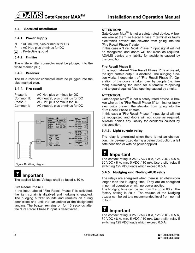
Figure 10: Wiring diagram
Important The applied Mains-Voltage shall be fused ≤ 10 A. Fire Recall Phase I If the input labeled "Fire Recall Phase I" is activated, the light curtain is disabled and nudging is enabled. The nudging buzzer sounds and remains on during door close and until the car arrives at the designated landing. The buzzer remains on for 15 seconds after the "Fire Recall Phase I" input is deactivated.
ATTENTION: GateKeeper MaxTM is not a safety rated device. A bro-ken wire at the "Fire Recall Phase I" terminal or faulty electronics prevent the elevator from going into the "Fire Recall Phase I" state. In this case a "Fire Recall Phase I" input signal will not be recognized and doors will not close as required. ADAMS denies any liability for accidents caused by this condition. Fire Recall Phase II If the input labeled "Fire Recall Phase II" is activated, the light curtain output is disabled. The nudging func-tion works independent of "Fire Recall Phase II". Op-eration of the doors is taken over by people (i.e. fire-men) eliminating the need for automatic re-opening and to guard against false opening caused by smoke. ATTENTION: GateKeeper MaxTM is not a safety rated device. A bro-ken wire at the "Fire Recall Phase II" terminal or faulty electronics prevent the elevator from going into the "Fire Recall Phase II" state. In this case a "Fire Recall Phase I" input signal will not be recognized and doors will not close as required. ADAMS denies any liability for accidents caused by this condition.
5.4.5. Light curtain relay
The relay is energized when there is not an obstruc-tion. It is de-energized during a beam obstruction, a fail safe condition or with no power applied.
Important The contact rating is 250 VAC / 8 A, 125 VDC / 0.5 A, 30 VDC / 8 A, min. 5 VDC / 10 mA. Use a pilot relay if switching 125 VDC loads which exceed 0.5 A.
5.4.6. Nudging and Nuding-AUX relay
The relays are energized when there is an obstruction longer than the Nudging time. They are de-energized in normal operation or with no power applied. The Nudging time can be set from 1 s up to 60 s. The factory setting is 20 s. The volume of the Nudging buzzer can be set to a recommended level from normal to loud.
Important The contact rating is 250 VAC / 8 A, 125 VDC / 0.5 A, 30 VDC / 8 A, min. 5 VDC / 10 mA. Use a pilot relay if switching 125 VDC loads which exceed 0.5 A.
Installation and Operation Manual GateKeeper MAXTM
1-800-323-0796 www.adamselevator.com 9 1-800-268-5392
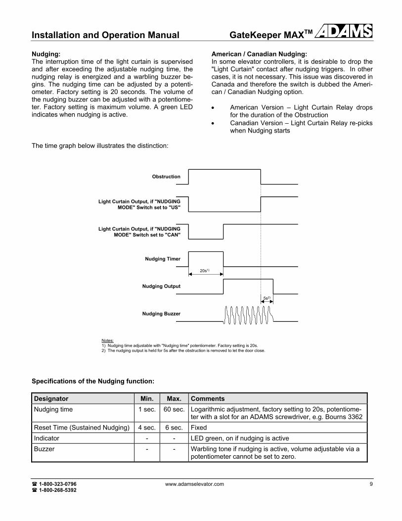
Nudging: The interruption time of the light curtain is supervised and after exceeding the adjustable nudging time, the nudging relay is energized and a warbling buzzer be-gins. The nudging time can be adjusted by a potenti-ometer. Factory setting is 20 seconds. The volume of the nudging buzzer can be adjusted with a potentiome-ter. Factory setting is maximum volume. A green LED indicates when nudging is active.
American / Canadian Nudging: In some elevator controllers, it is desirable to drop the "Light Curtain" contact after nudging triggers. In other cases, it is not necessary. This issue was discovered in Canada and therefore the switch is dubbed the Ameri-can / Canadian Nudging option. • American Version – Light Curtain Relay drops
for the duration of the Obstruction • Canadian Version – Light Curtain Relay re-picks
when Nudging starts
The time graph below illustrates the distinction:
5s2)
20s1)
Notes:1) Nudging time adjustable with "Nudging time" potentiometer. Factory setting is 20s.2) The nudging output is held for 5s after the obstruction is removed to let the door close.
Light Curtain Output, if "NUDGING MODE" Switch set to "US"
Obstruction
Nudging Timer
Nudging Output
Nudging Buzzer
Light Curtain Output, if "NUDGING MODE" Switch set to "CAN"
Specifications of the Nudging function: Designator Min. Max. Comments Nudging time 1 sec. 60 sec. Logarithmic adjustment, factory setting to 20s, potentiome-
ter with a slot for an ADAMS screwdriver, e.g. Bourns 3362 Reset Time (Sustained Nudging) 4 sec. 6 sec. Fixed Indicator - - LED green, on if nudging is active Buzzer - - Warbling tone if nudging is active, volume adjustable via a
potentiometer cannot be set to zero.
GateKeeper MAXTM Installation and Operation Manual
10 A850G7MAX-INS 1-800-323-0796 1-800-268-5392
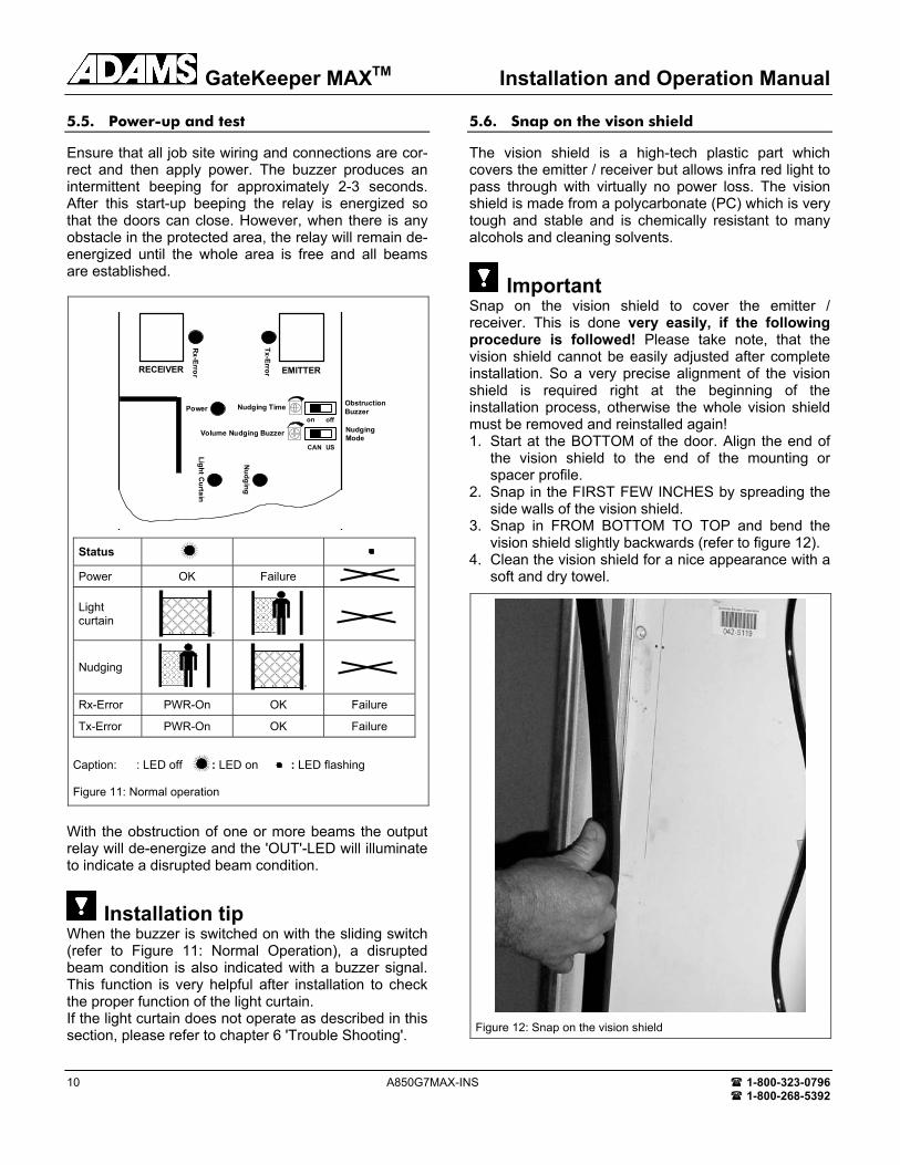
5.5. Power-up and test
Ensure that all job site wiring and connections are cor-rect and then apply power. The buzzer produces an intermittent beeping for approximately 2-3 seconds. After this start-up beeping the relay is energized so that the doors can close. However, when there is any obstacle in the protected area, the relay will remain de-energized until the whole area is free and all beams are established.
EMITTER
Tx-ErrorRECEIVER
Rx-Error
Light Curtain
Nudging
Power Nudging Time Obstruction Buzzer
NudgingMode
USCAN
offon
Volume Nudging Buzzer
Status
Power OK Failure
Light curtain
Nudging
Rx-Error PWR-On OK Failure
Tx-Error PWR-On OK Failure
Caption: : LED off : LED on : LED flashing Figure 11: Normal operation
With the obstruction of one or more beams the output relay will de-energize and the 'OUT'-LED will illuminate to indicate a disrupted beam condition.
Installation tip When the buzzer is switched on with the sliding switch (refer to Figure 11: Normal Operation), a disrupted beam condition is also indicated with a buzzer signal. This function is very helpful after installation to check the proper function of the light curtain. If the light curtain does not operate as described in this section, please refer to chapter 6 'Trouble Shooting'.
5.6. Snap on the vison shield
The vision shield is a high-tech plastic part which covers the emitter / receiver but allows infra red light to pass through with virtually no power loss. The vision shield is made from a polycarbonate (PC) which is very tough and stable and is chemically resistant to many alcohols and cleaning solvents.
Important Snap on the vision shield to cover the emitter / receiver. This is done very easily, if the following procedure is followed! Please take note, that the vision shield cannot be easily adjusted after complete installation. So a very precise alignment of the vision shield is required right at the beginning of the installation process, otherwise the whole vision shield must be removed and reinstalled again! 1. Start at the BOTTOM of the door. Align the end of
the vision shield to the end of the mounting or spacer profile.
2. Snap in the FIRST FEW INCHES by spreading the side walls of the vision shield.
3. Snap in FROM BOTTOM TO TOP and bend the vision shield slightly backwards (refer to figure 12).
4. Clean the vision shield for a nice appearance with a soft and dry towel.
Figure 12: Snap on the vision shield

Installation and Operation Manual GateKeeper MAXTM
1-800-323-0796 www.adamselevator.com 11 1-800-268-5392
5.7. Finished
Congratulations, you have successfully installed one of the most powerful, reliable and cost effective door pro-tection systems available today. It will benefit your customers for many years to come.
5.8. Maintenance
There is no special maintenance required for the light curtain. We recommend checking the proper function of the light curtain installation during normal elevator service. Proper function of the light curtain is evident when • the doors reopen immediately after an obstruction of
the protected area. • the sensors are fastened securely on the door and
strike jamb. • the cables are routed properly as described in sec-
tion '5.2 Cable Guidance'.
Important Do not use any aggressive cleaning solvents like Ace-tone or Trichloride or mechanically abrasive towels to clean the vision shields, the receiver edge and the transmitter edge. They may become "blind" and will not pass infra red light anymore. We strongly recommend using standard window cleaners or soap and water for cleaning.
5.9. Disposal
The light curtain should only be replaced if a similar door protection device is installed. Disposal should be done through state of the art recycling technology ac-cording to local rules and laws. There are no harmful materials used in the design and manufacture of the light curtain. Traces of such dangerous materials could be used in the electronic components but not in quanti-ties which are harmful to health.
GateKeeper MAXTM Installation and Operation Manual
12 A850G7MAX-INS 1-800-323-0796 1-800-268-5392
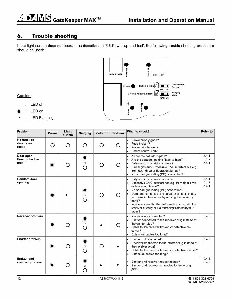
6. Trouble shooting
If the light curtain does not operate as described in '5.5 Power-up and test', the following trouble shooting procedure should be used:
Caption:
: LED off
: LED on
: LED Flashing
Problem Power Light curtain Nudging Rx-Error Tx-Error What to check? Refer to
No function door open (dead)
• Power supply good? • Fuse broken? • Power wire broken? • Defect control unit?
Door open Free protective area
or
• All beams not interrupted? • Are the sensors looking "face-to-face"? • Dirty sensors or vision shields? • Bad alignment? Excessive EMC interference e.g.
from door drive or fluorecent lamps? • No or bad grounding (PE) connection?
5.1.1 5.1.2 5.4.1
Random door opening
or
• Dirty sensors or vision shields? • Excessive EMC interference e.g. from door drive
or fluorecent lamps? • No or bad grounding (PE) connection? • Damaged cable to the receiver or emitter, check
for break in the cables by moving the cable by hand?
• Interference with other infra red sensors with the receiver directly or via mirroring from shiny sur-faces?
5.1.1 5.1.2 5.4.1
Receiver problem
or
• Receiver not connected? • Emitter connected to the receiver plug instead of
the emitter plug? • Cable to the receiver broken or defective re-
ceiver? • Extension cables too long?
5.4.3
Emitter problem
or
• Emitter not connected? • Receiver connected to the emitter plug instead of
the receiver plug? • Cable to the receiver broken or defective emitter?• Extension cables too long?
5.4.2
Emitter and receiver problem
or
• Emitter and receiver not connected? • Emitter and receiver connected to the wrong
jack?
5.4.2 5.4.3
EMITTER
Tx-ErrorRECEIVER
Rx-Error
Light Curtain
Nudging
Power Nudging Time Obstruction Buzzer
NudgingMode
USCAN
offon
Volume Nudging Buzzer
Installation and Operation Manual GateKeeper MAXTM
1-800-323-0796 www.adamselevator.com 13 1-800-268-5392
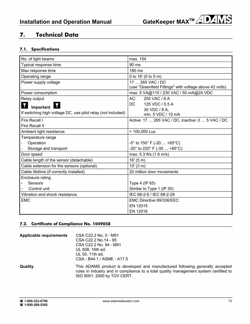
7. Technical Data
7.1. Specifications
No. of light beams max. 154 Typical response time 90 ms Max response time 180 ms Operating range 0 to 16' (0 to 5 m) Power supply voltage 17 … 265 VAC / DC
(use "Greenfield Fittings" with voltage above 42 volts) Power consumption max. 5 VA@115 / 230 VAC / 50 mA@24 VDC Relay output
Important If switching high voltage DC, use pilot relay (not included)
AC: 250 VAC / 8 A DC 125 VDC / 0.5 A 30 VDC / 8 A, min. 5 VDC / 10 mA
Fire Recall I Fire Recall II
Active: 17 … 265 VAC / DC, inactive: 0 … 5 VAC / DC
Ambient light resistance > 100,000 Lux Temperature range - Operation - Storage and transport
-5° to 150° F (-20 … +65°C) -20° to 220° F (-30 … +85°C)
Door speed max. 5.3 ft/s (1.6 m/s) Cable length of the sensor (detachable) 16' (5 m) Cable extension for the sensors (optional) 10' (3 m) Cable lifetime (if correctly installed) 20 million door movements Enclosure rating - Sensors - Control unit
Type 4 (IP 65) Similar to Type 1 (IP 30)
Vibration and shock resistance IEC 68-2-6 / IEC 68-2-29 EMC EMC Directive 89/336/EEC
EN 12015 EN 12016
7.2. Certificate of Compliance No. 1049058
Applicable requirements CSA C22.2 No. 0 - M91 CSA C22.2 No.14 - 95 CSA C22.2 No. 94 - M91 UL 508, 16th ed. UL 50, 11th ed. CSA - B44.1 / ASME - A17.5
Quality This ADAMS product is developed and manufactured following generally accepted rules in industry and in compliance to a total quality management system certified to ISO 9001: 2000 by TÜV CERT.
GateKeeper MAXTM Installation and Operation Manual
14 A850G7MAX-INS 1-800-323-0796 1-800-268-5392
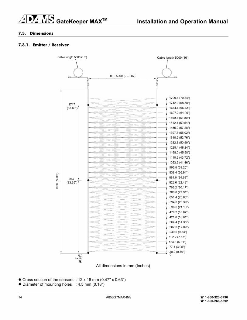
7.3. Dimensions
7.3.1. Emitter / Receiver
0 ... 5000 (0 ... 16')
2000
(78.
75")
7(0
.28"
)
1799.4 (70.84")1742.0 (68.58")1684.6 (66.32")1627.2 (64.06")1569.8 (61.80")1512.4 (59.54")1455.0 (57.28")1397.6 (55.02")1340.2 (52.76")1282.8 (50.50")1225.4 (48.24")1168.0 (45.98")1110.6 (43.72")1053.2 (41.46")995.8 (39.20")938.4 (36.94")
881.0 (34.69")823.6 (32.43")766.2 (30.17")708.8 (27.91")651.4 (25.65")594.0 (23.39")536.6 (21.13")479.2 (18.87")421.8 (16.61")364.4 (14.35")307.0 (12.09")249.6 (9.83")192.2 (7.57")134.8 (5.31")77.4 (3.05")20.0 (0.79")0
1717 (67.60")
847(33.35")
Cable length 5000 (16')
All dimensions in mm (Inches)
Cross section of the sensors : 12 x 16 mm (0.47" x 0.63") Diameter of mounting holes : 4.5 mm (0.18")
1900
(74.
80“)
Cable length 5000 (16’)
Installation and Operation Manual GateKeeper MAXTM
1-800-323-0796 www.adamselevator.com 15 1-800-268-5392
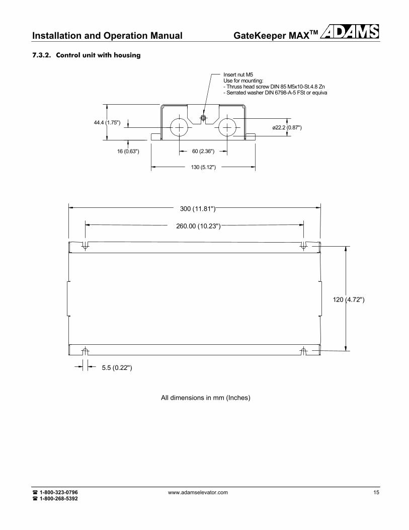
7.3.2. Control unit with housing
130 (5.12'')
60 (2.36'')
ø22.2 (0.87'')44.4 (1.75'')
16 (0.63'')
Insert nut M5Use for mounting:- Thruss head screw DIN 85 M5x10-St.4.8 Zn- Serrated washer DIN 6798-A-5 FSt or equiva
300 (11.81'')
260.00 (10.23'')
120 (4.72'')
5.5 (0.22'')
All dimensions in mm (Inches)

GateKeeper MAXTM Installation and Operation Manual
16 A850G7MAX-INS 1-800-323-0796 1-800-268-5392
7.4. List of part numbers
7.4.1. Complete units and accessories
ADAMS Part No. Description A850G7MAX1) GateKeeper MAXTM/7' including mounting kit for door height up to 7', with universal nudging controller A850G10MAX1) GateKeeper MAXTM/10' including mounting kit for door height greater than 7' up to 10', with universal nudging controller A850G7MAX-P1 GateKeeper MAXTM Control Unit , including universal nudging controller
Note: 1) For the bill of material please refer to table 7.4.3 (below)
7.4.2. Spare parts
ADAMS Part No. Description A850G7-R1 Receiver A850G7-T1 Emitter A850G7-RR1 Cable Receiver 16' A850G7-RT1 Cable Emitter 16' A850G7-RR2 Cable Extension Receiver 10' A850G7-RT2 Cable Extension Emitter 10' A850G7-LGW Cable Guide Wire A850G7-SP Spacer Profile 7' A850G10-SP Spacer Profile >7'-10' A850G7-MP Mounting Profile 7' A850G10-MP Mounting Profile >7'-10' A850G7-VS Vision Shield 7' A850G10-VS Vision Shield >7'-10' A850G7MAX-INS GateKeeper MAXTM Installation Manual
7.4.3. Bill of materials of complete units
ADAMS Part No. Description No. of Units in the complete Package
A850G7MAX-P1 GateKeeper MAXTM control unit, including universal nudging controller 1 A850G7-R1 Receiver 1 A850G7-T1 Emitter 1 A850G7-RR1 Cable Receiver 16' 1 A850G7-RT1 Cable Emitter 16' 1 A850G7-LGW Cable Guide Wire 2 A850G7-SP Spacer Profile 7' 22) A850G10-SP Spacer Profile >7'-10' 22) A850G7-MP Mounting Profile 7' 12) A850G10-MP Mounting Profile >7'-10' 12) A850G7-VS Vision Shield 7' 22) A850G10-VS Vision Shield >7'-10' 22) A850G7MAX-INS Installation Manual 1 A850G7-HW Hardware Bag containing the necessary screws, cable binders and cable holders 1
Notes: 2) 7' units in 7' systems only (A850G7, A850G7MAX), 10' units in 10' systems only (A850G10, A850G10MAX)