important notes on the methods and procedures used in … · serviceability limit state...
TRANSCRIPT
The following European standards, together with their respective National Annexes are referenced in Albion Engineer software:
Important notes on the methods and procedures used in Albion Engineer software version 4.0 (Eurocode design).
BS EN 1990:2002 Basis of structural design.
BS EN 1991-1-1:2002 Actions on structures – Densities, self weight, imposed loads for buildings.
BS EN 1991-1-3:2003 Actions on structures – General actions – Snow loads.
BS EN 1991-1-4:2005 Actions on structures – General actions – Wind actions.
BS EN 1991-1-7:2006 Actions on structures – General actions – Accidental actions
BS EN 1993-1-1:2005 Design of steel structures – General rules and rules for buildings.
BS EN 1993-1-3:2006 General rules – Supplementary rules for cold formed members and sheeting.
BS EN 1993-1-5 Design of steel structures: Plated structural elements.
Calculation of effective section properties.Section properties of Albion zed, eaves beam and cee sections have been calculated in accordance with BS EN 1991-1-3:2006.Ultimate load capacities and deflection coefficients have been based on analytical models following full scale testing at Birmingham University under the supervision of Dr Jian Yang.
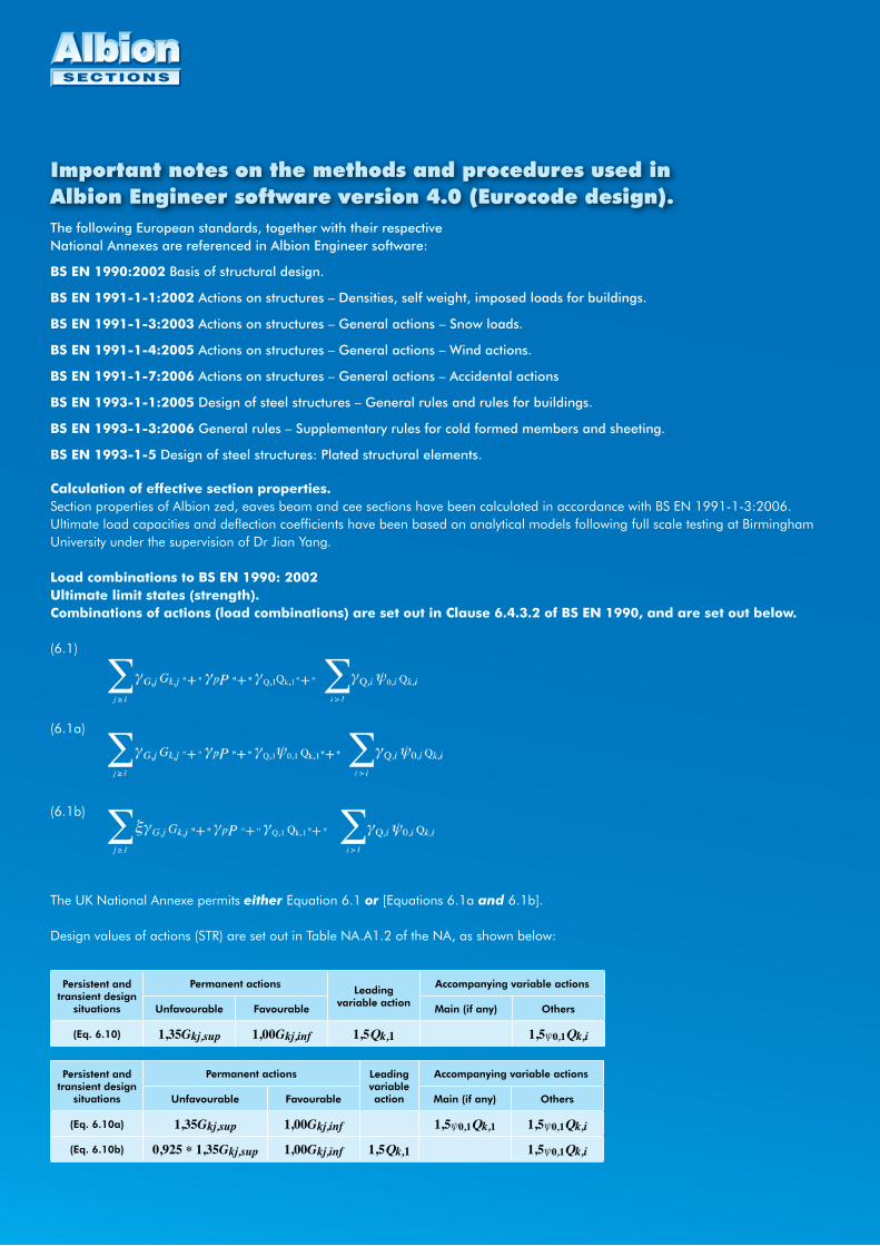
Load combinations to BS EN 1990: 2002Ultimate limit states (strength).Combinations of actions (load combinations) are set out in Clause 6.4.3.2 of BS EN 1990, and are set out below.
(6.1)
(6.1a)
(6.1b)
The UK National Annexe permits either Equation 6.1 or [Equations 6.1a and 6.1b].
Design values of actions (STR) are set out in Table NA.A1.2 of the NA, as shown below:
Persistent and transient design
situations
Permanent actionsLeading
variable action
Accompanying variable actions
Unfavourable Favourable Main (if any) Others
(Eq. 6.10) 1,35Gkj,sup 1,00Gkj,inf 1,5Qk,1 1,5ψ0,1Qk,i
Persistent and transient design
situations
Permanent actions Leading variable action
Accompanying variable actions
Unfavourable Favourable Main (if any) Others
(Eq. 6.10a) 1,35Gkj,sup 1,00Gkj,inf 1,5ψ0,1Qk,1 1,5ψ0,1Qk,i
(Eq. 6.10b) 0,925 * 1,35Gkj,sup 1,00Gkj,inf 1,5Qk,1 1,5ψ0,1Qk,i
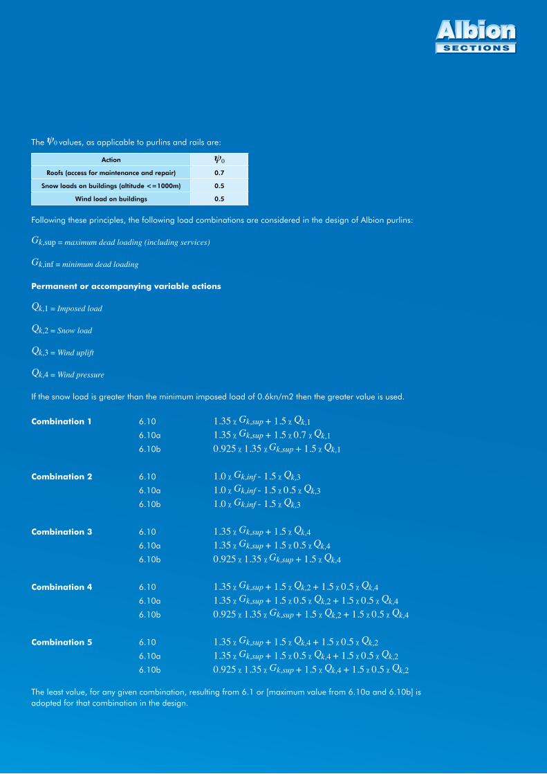
The ψ0 values, as applicable to purlins and rails are:
Action ψ0
Roofs (access for maintenance and repair) 0.7
Snow loads on buildings (altitude <=1000m) 0.5
Wind load on buildings 0.5
Following these principles, the following load combinations are considered in the design of Albion purlins:
Gk,sup = maximum dead loading (including services) Gk,inf = minimum dead loading
Permanent or accompanying variable actions
Qk,1 = Imposed load
Qk,2 = Snow load
Qk,3 = Wind uplift
Qk,4 = Wind pressure
If the snow load is greater than the minimum imposed load of 0.6kn/m2 then the greater value is used.
Combination 1 6.10 1.35 χ Gk,sup + 1.5 χ Qk,1 6.10a 1.35 χ Gk,sup + 1.5 χ 0.7 χ Qk,1 6.10b 0.925 χ 1.35 χ Gk,sup + 1.5 χ Qk,1
Combination 2 6.10 1.0 χ Gk,inf - 1.5 χ Qk,3
6.10a 1.0 χ Gk,inf - 1.5 χ 0.5 χ Qk,3 6.10b 1.0 χ Gk,inf - 1.5 χ Qk,3
Combination 3 6.10 1.35 χ Gk,sup + 1.5 χ Qk,4 6.10a 1.35 χ Gk,sup + 1.5 χ 0.5 χ Qk,4 6.10b 0.925 χ 1.35 χ Gk,sup + 1.5 χ Qk,4
Combination 4 6.10 1.35 χ Gk,sup + 1.5 χ Qk,2 + 1.5 χ 0.5 χ Qk,4 6.10a 1.35 χ Gk,sup + 1.5 χ 0.5 χ Qk,2 + 1.5 χ 0.5 χ Qk,4 6.10b 0.925 χ 1.35 χ Gk,sup + 1.5 χ Qk,2 + 1.5 χ 0.5 χ Qk,4
Combination 5 6.10 1.35 χ Gk,sup + 1.5 χ Qk,4 + 1.5 χ 0.5 χ Qk,2 6.10a 1.35 χ Gk,sup + 1.5 χ 0.5 χ Qk,4 + 1.5 χ 0.5 χ Qk,2 6.10b 0.925 χ 1.35 χ Gk,sup + 1.5 χ Qk,4 + 1.5 χ 0.5 χ Qk,2
The least value, for any given combination, resulting from 6.1 or [maximum value from 6.10a and 6.10b] is adopted for that combination in the design.

Serviceability limit state (deflection).
The UK National Annexe to BS EN 1993-1-1 (Clauses NA.2.23 and 24) states that vertical and horizontal deflections may be checked using the characteristic combination with variable loads only i.e. permanent dead loads should not be included. The characteristic combination, given by Equation 6.14b, is noted below:
The default setting in the software is used to limit purlin deflection using dead load + service load + imposed load to a value of span/180.
The limiting value may be set by the user to account for special design cases, i.e. low pitched roofs, claddings requiring stiffer sub-structures, i.e. tiles and battons, and other special cases.
Calculated deflections are also noted in the result ouput for the following load cases: Imposed load only Wind pressure only Wind suction onlyAlso, serviceability combinations (6.14b) Imposed load + 0.5 x Wind pressure load Wind pressure + 0.7 x Imposed load
It is up to the software user to decide whether the calculated deflections are acceptable.
Cladding rail design
Albion rail designs are simpler in that the primary load case is wind loading.
For ultimate strength, a load factor of 1.5 is adopted. For serviceability deflections, only the wind loading (pressure and suction) is considered.
Eaves beam design.
The eaves beam is subject to vertical dead and imposed loading with coexistent side suction or pressure or roof uplift with coexistent side suction or pressure.
Load combinations are considered, as for the purlin design, to result bending unity coefficients of applied moments divided by ultimate strength in both vertical and horizontal directions.
The worst case is resulted as percentage efficiency.
As with the purlin design, vertical deflection due to combination dead load + service load + imposed load is checked against a default limit of span/200. This default may be changed by the user.
Vertical deflections due to variable loads only are noted on the results printout, to be assessed by the user as acceptable.
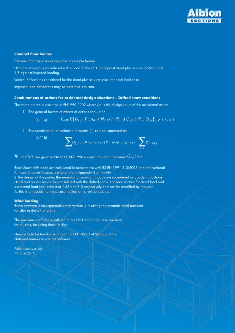
Combinations of actions for accidental design situations – Drifted snow conditions
The combination is provided in EN1990:2002 where Ad is the design value of the accidental action.
(1) The general format of effects of actions should be:
(6.11a) Ed = E{Gk,j ; P ; Ad ; (ψ1,1 or ψ2,1) Qk,1 ; ψ2,i Qk,i} j ≥ 1 ; i > 1
(2) The combination of actions in brackets { } can be expressed as:
(6.11b)
ψ1 and ψ2 are given in NA to BS EN 1990 as zero, this then becomes Gk,j ; Ad
Basic Snow drift loads are calculated in accordance with BS EN 1991-1-3:2003 and the National Annexe. Snow drift cases are taken from Appendix B of the NA.In the design of the purlin, the exceptional snow drift loads are considered as accidental actions.Dead and service loads are considered with the drifted snow. The load factors for dead load and accidental load (Ad) default at 1.35 and 1.0 respectively and can be modified by the user.As this is an accidental load case, deflection is not considered.
Wind loadingBreve software is incorporated within version 4 resulting the dynamic wind pressurefor sites in the UK and Eire.
The pressure coefficients outlined in the UK National Annexe are usedfor all sites, including those in Eire.
Users should be familiar with both BS EN 1991-1-4:2005 and theNational Annexe to use the software.
Albion Sections Ltd19 June 2012
Channel floor beams.
Channel floor beams are designed as simple beams.
Ultimate strength is considered with a load factor of 1.35 against dead plus service loading and 1.5 against imposed loading.
Vertical deflections considered for the dead plus services plus imposed load case.
Imposed load deflections may be obtained pro rata.