improved fluxgate for compasses and position sensors
TRANSCRIPT
543 Journal of Magnetism and Magnetic Materials 83 (1990) 543-544 North-Holland
IMPROVED FLUXGATE FOR COMPASSES AND POSITION SENSORS
Pave1 RIPKA
Czech Technical University, Electrotechnical Faculty, Dept. of Measurement, I662 7 Prague 6, Czechoslocakra
Fluxgate cores from etched rings of Permalloy sheet are proposed. They achieve better long-term stability and lower angle
error (4’ error was reached). Dynamic performance was investigated - 5 kHz band-pass was obtained and 5 ms impulses were
measured with an amorphous core.
Fluxgate magnetometers use the nonlinearity of the magnetisation curve of ferromagnetic core, which is periodically saturated by an ac excitation field. In the presence of the measured magnetic field the core is magnetised unsymmetrically and changes in the shape of induced voltage in sense coil appear. The most used method for evaluation of the sensor output is selective measurement of the second harmonica1 component. Fluxgate magnetometers measure the dc or low- frequency ac magnetic field in the direction of the sensing coil. Now, especially after the failure of the cesium magnetometer during the Magsat mission and with optical fibre magnetometers have fallen short of expectations [l], attention is again being paid to this classical method.
Ring-core geometry has been widely used because of better long-term stability and lower noise of such sensors. Two orthogonal components of magnetic field may be measured with one sensor having two sense coils mutually perpendicular. In addition, the angle error in vector measurements is decreased typically from 30’ for open-core sensors to 10’ for those of ring-core design.
The theory of operation of the fluxgate was extended to the ring-core type in ref. [2]. We have tested various nonselective methods of output signal evaluation and compared them with traditional evaluation of second harmonics: self-oscillating magnetometers and those ones using peak detection had higher noise and poor stability; the method of evaluating phase-shifts in in- duced voltage proposed by Heinecke [3] requires a long time for measurement (about 0.6 s for 1 nT resolution) and brought no new advantage. The conclusion of this study was that the classical method using lock-in detec- tion with reference at second harmonics of the excita- tion frequency cannot be replaced by any simpler method in very low-noise magnetometers. Although, all even harmonic components in the induced voltage bear the information of the measured field, we demonstrated the commonly used second harmonic to have the best signal-to-noise ratio. Its linearity is worse compared to
0304-8853/90/$03.50 0 Elsevier Science Publishers B.V. (North-Holland)
the fourth harmonic, but it may be improved using feedback techniques.
In our devices we use 5 kHz sinusoidal excitation with a peak core drive current 100 times larger than the core saturation current. The output voltage is amplified in a two-stage RC filter and then synchronously demod- ulated. Pre-filtering is necessary due to the limited dynamical range of the PSD (80 dB at 10 kHz) and a large interference signal at the basic frequency of the driving current (about 500 mV for 2000 turns, sensitiv- ity is 10 to 50 uV/nT). We have tested several switch- capacitor filters and n-path synchronous integrators as pre-filters, but they cannot be used due to their nonlin- earity which causes in this special case a false signal on the measured frequency of the 2nd harmonic.
Because of their low noise, permalloys are still used for precise low-field magnetometer cores. The need of winding and high-temperature annealing of the core make the sensor the most costly part of the magnetome- ter. We propose here a different technology in sensor manufacturing: the sensor core in the form of annular circles is made by etching and can be annealed before mounting into the coil. This geometry offers higher homogeneity of the core because of the absence of ends in the case of cores wound from tape. It provides: 1. Better long-term stability, 2. Additional increase of the angle accuracy, 3. Lower disturbing output on exciting frequency
(caused by imperfect balance of the sensor). Using the same material, PY 79, zero stability was
increased from 750 to 150 pT/h. “High frequency” noise in the range 10 Hz to 1 Hz remained at 600 pT p-p (100 pT rms). After 0.7 Hz cut-off frequency low-pass filtering, peak-to-peak variation are within a limit of 150 pT for a 5 min period. Although the spectral density is widely used, we prefer the p-p stabil- ity level for description of the sensor noise. After analysing statistical properties of noise in several flux- gates, we recognized that the Gaussian character cannot be proved and the ratio between p-p and rms level

544 P. Ripku / Improoedfluxgate
* 4 -c,- “7
- ,^ _ - 1 a,nx 3EC.O
3r;le (degVXSi
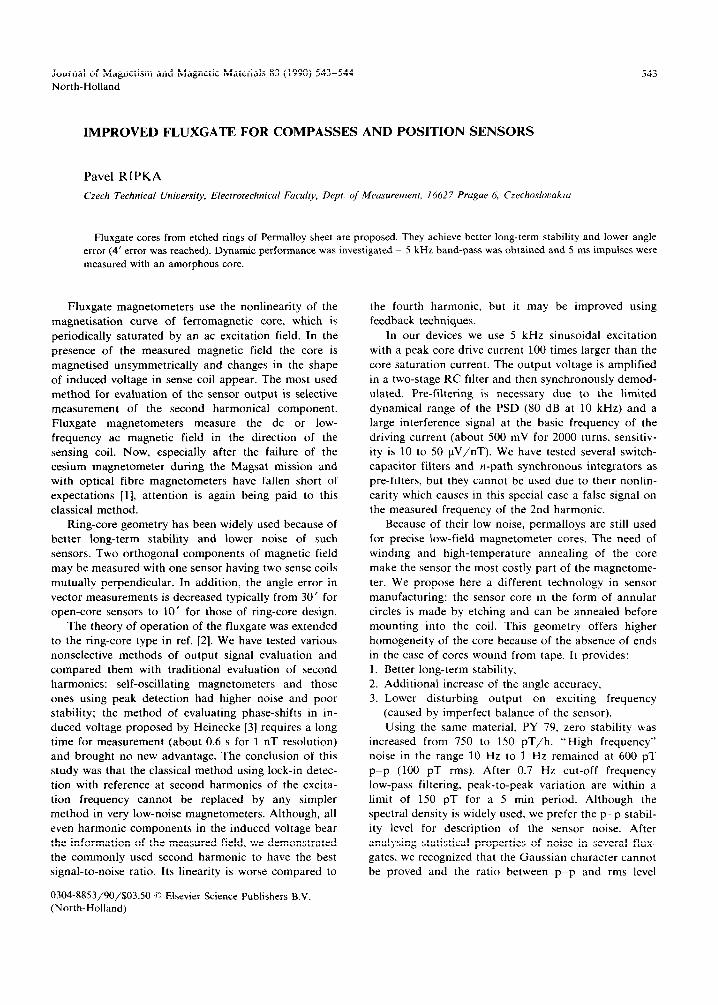
Fig. 1. Angle error of the compensated flux gate.
cannot be easily expressed, although it lies between 6 to 8. Drift of sensor offset also depends on its mechanical stability. For sensor coil framework we use machinable glass “Micalex” containing melted mica.
We measured the angle error of the sensor using feedback in order to compensate for nonlinearity in both sensing coils. The angle was then calculated from
the ratio of compensation currents. Sensor offset and error of perpendicularity between coils were compensated. Sensor was rotated and angle was measured by nonmagnetic theodolite. The maximum error was below 4’ and might be caused partly by nonhomogeneity and variations of Earth’s field during measurement ~ the reproducibility was very poor, typi- cal results are shown in fig. 1.
Dynamic performance of the fluxgate was investi- gated in order to establish its ability to measure ac and impulse fields. It was shown by Kono et al. [4] that with a proper design of the magnetometer, the band-pass can be extended to 300 Hz with 5% accuracy. We have reached (for fields higher than IO nT) a band-pass of 1 kHz for Permalloy core fluxgate by improvement of the sensor electronics. Another way to increase the cut-off frequency is increasing the driving frequency. Co-based amorphous alloys are useful in this case, because of their higher resistivity and low magnetostriction. We have made an oval-shape sensor wound from
Fig. 3. Step response of the sensor.
Co,, Fe, B,, tape (manufactured by ZFW AW Dresden. GDR). Maximum sensitivity was reached for 20 kHz driving frequency, but at 75 kHz, which we have used, the sensitivity was lowered only five times (see fig. 2). For higher frequencies it was, however, difficult to guarantee the saturation of the whole core. 5 kHz band-pass was reached in this case. The amplitude of impulses with a duration longer than 5 ms can be measured with 5% accuracy (see fig. 3). We know of no other method for measuring such short separate im- pulses below 100 nT ~ even the best induction coils with magnetic cores cannot be used because of their own noise. Another application of the ac fluxgate is for position measurements, where the measured object is either the source of the ac magnetic field, or the flux-gate itself measures the direction of magnetic field from two or more artificial ac field sources of different frequen- cies. We also consider the possibility of using the flux- gate for reading marks made by permanent magnets from the moving locomotive engine.
References
[I] R. Langel. Geophys. Res. Lett. 9 (1982) 243.
[2] P. Ripka, Phys. Scripta (to he published).
[3] R. Heinecke. Tech. Messen 48 (1981) 76.
[4] M. Kono et al., J. Geomag. Geol. 36 (1984) 149
Fig. 2. Frequency dependence of (a) phase shift, (b) sensitivity for exciting frequency: * 1 kHz, x 5 kHz, Permalloy core; * 75 kHz. amorphous Co based core.