improved signal-to-noise ratio performance in magnetic resonance imaging by using a multilayered...
TRANSCRIPT

756 IEEE JOURNAL OF BIOMEDICAL AND HEALTH INFORMATICS, VOL. 17, NO. 3, MAY 2013
Improved Signal-to-Noise Ratio Performancein Magnetic Resonance Imaging by Using
a Multilayered Surface Coil Array—ASimulation Study
Dandan Liang, Hon Tat Hui, Senior Member, IEEE, and Tat Soon Yeo, Fellow, IEEE
Abstract—A multilayered surface coil array for magnetic reso-nance imaging with an improved signal-to-noise ratio (SNR) per-formance is introduced and investigated by a simulation study. Byusing an effective decoupling method, the strong mutual couplingeffect between the coil layers can be accurately removed, leadingto a coherent combination of the signals of the individual coils.This results in a much stronger received signal power which in-creases with the number of coil layers in the array. This, togetherwith a smaller rate of increase of noise power with the numberof coil layers, leads to a net increase in the SNR of array outputwith the number of coil layers in the array. Rigorous numericalsimulation examples have been carried out to confirm and verifythe performance of the new array.
Index Terms—Magnetic resonance imaging (MRI), mutual cou-pling, signal combining, signal-to-noise ratio (SNR), surface coilarray.
I. INTRODUCTION
RADIO frequency (RF) coils are key hardware componentsin a magnetic resonance imaging (MRI) system, and they
are used for first generating RF pulses at Larmor frequency andthen picking up the signals emitted by the nuclei at the samefrequency. The received signals are to be programmed for imagereconstruction, so the image accuracy depends crucially on thesignal-to-noise ratio (SNR) of the receiving coils in the system.A surface coil is particularly used as a receiver coil for MRIsignals to obtain spectra and images from tissues close to thesurface due to its small field of view (FOV), which decreases theamount of noise that is received from the sample, thus, achievinga higher SNR [1].
In clinical imaging, it is desirable to have a large FOV be-cause the region of interest is often not known especially if alarge sample is being imaged. A large coil fails to be an effectivesolution to this situation even though it provides a large FOVbecause it also captures more noise and, thus, sacrifices SNR.Repeatedly imaging with repositioning the small coil is a goodway to keep the advantage of a high SNR, but it is very timeconsuming. Therefore, a feasible solution is to use a coil ar-ray, which consists of closely positioned small surface coils for
Manuscript received August 12, 2012; revised December 8, 2012; acceptedMarch 11, 2013. Date of publication March 18, 2013; date of current versionMay 1, 2013.
The authors are with the Department of Electrical and Computer En-gineering, National University of Singapore, Singapore 117576 (e-mail:[email protected]; [email protected]; [email protected]).
Digital Object Identifier 10.1109/JBHI.2013.2253113
simultaneously receiving MRI signals to provide a high SNRover a large region of sensitivity without any penalty in imagingtime [1]. However, the strong mutual coupling within the arraydue to the close positioning of coil elements can make the coilsoff resonant at desirable operating frequency of the system, andseriously weaken the strength of received signal and therebygreatly lower the SNR of the produced image.
The detrimental mutual coupling effect could be minimizedby partially overlapping the adjacent coils and/or using low in-put impedance amplifiers in the design of surface coil arrays [2].However, overlapping is not a pertinent decoupling method forMRI because it reduces the imaged area, and also constrains thepositioning of the coils [3], [4]. On the other hand, the use of lowinput impedance preamplifiers for removing the coupling amongnonoverlapping coil elements sacrifices the condition of maxi-mum power transfer [3]. Because of these drawbacks, a moreeffective decoupling method was recently introduced [3], [5],which relies on using a new mutual impedance characteriza-tion method. In [5], this method was demonstrated by initialmeasurements on two vertically stacked coils, showing an al-most double increase in the output combined voltage. In [6],this method was further used to design a vertical surface coil ar-ray whose SNR at the combined signal output can be increasedat no additional costs. While arrays have long been shown tobe able to increase the received SNR in wireless communica-tions [7], the same benefit for MRI phased arrays was shown tobe obtained for the first time only when an effective decouplingmethod was used [3], [6].
In this paper, based on the original work in [6], we proposea novel design of a multilayered surface coil array to furtherimprove both the SNR performance and FOV of surface coilarrays in MRI. It will be shown that how the single verticaldimension of array construction in [6] can be extended furtherin horizontal direction so as to acquire the benefits of both theincreased SNR by a vertical array construction and the enlargedFOV by the horizontal construction. We will demonstrate howthe performance of this “super” coil array is improved by theuse of the new decoupling technique in [3] and [6].
II. DERIVATION OF THE SNR FOR THE MULTILAYERED
SURFACE COIL ARRAY
The proposed multilayered surface coil array is shown inFig. 1. It consists of multiple surface coils in both the vertical and
2168-2194/$31.00 © 2013 IEEE

LIANG et al.: IMPROVED SIGNAL-TO-NOISE RATIO PERFORMANCE IN MAGNETIC RESONANCE IMAGING 757
Fig. 1. Configuration of the proposed multilayered surface coil array with mlayers of coils and n coils in each layer.
horizontal directions. Shown in Fig. 1 is an m × n configurationwith m surface coil arrays each of which has n coils. Each coilelement is defined by its position in the array, i.e., coil ij is thecoil element in the ith horizontal layer and the jth vertical stack.The coil elements in each horizontal layer are closely positionedside by side with a very small gap g between adjacent coils soas to cover a large imaged area. The coil layers are closelystacked in the vertical direction with a separation d betweenadjacent layers. When d is small, a number of layers can bestacked together and the result will be a significant increase inthe SNR of the array signals, as shown in the next section. Thisis a direct extension of the principle of increasing the SNR byusing vertically stacked coils in [5], [6] to construct a surfacecoil array.
In this multilayered surface coil array, each coil element isconnected to a low-noise amplifier (LNA) through a matchingcircuit. The received voltages by coils in the same vertical stackare combined together to form a single output voltage. Obvi-ously, as the coils are placed in close proximity to each other,the mutual coupling effect between them is very strong andneeds to be properly handled [3]. As shown in Fig. 1, the re-ceived signals from the coil elements (after passing through theLNA stage) are passed through a decoupling network denotedby T−1
v , which removes the mutual coupling effect in the signalsbefore they are combined together. This decoupling network canbe realized by lossless phase shifters and transformers as thoseused for the connection of the phased coil array in [2]. As shownbelow, this decoupling network is crucial to the design of themultilayered surface coil array.
The decoupling network T−1v shown in Fig. 1 has m × n
input ports and n output ports. The function of this decouplingnetwork is best described by the following equation:
V′ = T−1v V (1)
where V = [V11 , V12 , . . . , V1n , V21 , V22 , . . . , V2n , . . . , Vm1 ,Vm2 , . . . , Vmn ]T is the vector of the coupled voltages
received by the coil elements and V′ = [V ′11 , V
′12 , . . . ,
V ′1n , V ′
21 , V′22 , . . . , V
′2n , . . . , V ′
m1 , V′m2 , . . . , V
′m1 ]
T is the vectorof the decoupled voltages in which the mutual couplingeffect has been removed by the decoupling matrix T−1
v . Thedecoupled voltages from the coils in the same vertical stackV ′
i1 , V′i2 , . . . , V
′in (i = 1, 2, . . . ,m) are then summed up to form
a signal output voltage which contains the MR signal emanatingfrom the area covered by that particular stack of coils. In thisway, the MR signals from the multilayer surface coil array aredivided into n outputs corresponding to the number of verticalstacks of coils. Thus, like the conventional single-layeredsurface coil array which provides n MR signals from the nsignal surface coil elements, the multilayered surface coil arrayalso provides n MR signal outputs, but each of them is thesummation of the signals from m vertically stacked coils. InFig. 1, the function of the decoupling network and the n voltageadders is denoted as a signal combiner W.
In an MRI system, the output voltage of each coil consists ofthe signal voltage and the noise voltage, both of which sufferfrom the mutual coupling effect. The noise voltage comprisesthe circuit noise voltage and the sample noise voltage. Thecircuit noise is mainly originating from the LNA connected tothe coil [8] and the sample noise is mainly the random electricfield radiated from the sample and picked up by the coil [2].Since the sample noise power is dependent on frequency, and inturn on the field strength (the static B0 field) of the system, it isusually substantially weaker than the circuit noise in low-fieldsystems (B0 < 1 T) [9]–[12]. So for a low-field MRI system withnegligible sample noise, the received terminal voltage vector Vt
for the multilayered surface coil array can be written as the sumof the signal voltage vector [V in (1)] and the circuit noisevoltage vector N as
Vt= V + N (2)
where the three vectors above all have the same number ofm × n elements, each of which corresponds to the voltage type,total, signal, or noise, developed at the terminal of the respectivecoil element in the array.
The signal voltage received by each coil in the array is a cou-pled voltage, and it can be considered to have three components.For example, the received signal voltage of coil ij, denoted byVij , can be written as
Vij = Uij + Vij ss + Vij ds ≈ V ′ij + Vij ss + Vij ds (3)
where Uij is the uncoupled signal voltage received by coil ijwhen all the other coils in the array were removed, and thisvoltage is approximately equal to the decoupled signal voltageV ′
ij . The second component Vij ss is the signal voltages coupledto coil ij from the other coils in the same vertical stack (i.e., coilpj with p = 1, 2, . . . ,m, and p �= i). The subscript “ss” denotesthe “same stack.” Vij ss can be represented using the receivingmutual impedance as follows:
Vij ss =m∑
p=1&p �=i
Zij,pjt
ZLVpj (4)

758 IEEE JOURNAL OF BIOMEDICAL AND HEALTH INFORMATICS, VOL. 17, NO. 3, MAY 2013
where Zij,pjt is the receiving mutual impedance of coil ij and
coil pj in the jth stack, and Vpj is the coupled signal voltageof coil pj. The third component in (3) Vij ds is the signal volt-ages coupled to coil ij from the coils in the other stacks (i.e.,coil pq with p = 1, 2, . . . ,m; q = 1, 2, . . . , n, and q �= j). Thesubscript “ds” denotes “different stacks.” Using the receivingmutual impedances between the coils, Vij ds can be similarlyrepresented as
Vij ds =n∑
q=1&q �=j
m∑
p=1
Zij,pqt
ZLVpq (5)
where Zij,pqt is the receiving mutual impedance between coil ij
and coil pq, and Vpq is the coupled signal voltage of coil pq.With the aforementioned division of the signal voltages into
three components, we can define the output SNR of the multi-layered surface coil array as follows [13]–[15]:
SNRdj =
12 Re
{1
Z ∗i n
} ∣∣∑mi=1 V ′
ij
∣∣2
12 Re
{1
Z ∗in
} ⟨∣∣∑mi=1 N ′
ij
∣∣2⟩ =
∣∣∑mi=1 V ′
ij
∣∣2⟨∣∣∑m
i=1 N ′ij
∣∣2⟩
(6)where SNRd
j denotes the SNR of the combined signal and noisevoltages of the jth stack of coils and 〈〉 represents the expectationoperation. The superscript “d” is to indicate that the signal andnoise voltages have been decoupled with respect to the mutualcoupling effect. In (6), Zin is the input impedance of the receiverconnected to the voltage adder for summing up the signals ofcoils in the jth stack and N ′
ij is the ijth element of the decouplednoise voltage vector N′ given by
N′ = T−1v N. (7)
It will be shown in the next section that the improved SNRperformance of the multilayered surface coil array is possibleonly when the decoupling matrix T−1
v is properly designed. Inorder to demonstrate this, we also define the following SNR withthe decoupling matrix T−1
v removed such that the output signalsfrom the coil array are directly combined. This is the SNR ofthe signal voltages directly obtained from the coil elements, andcan be represented as
SNRcj =
12 Re
{1
Z ∗i n
} ∣∣∑mi=1
(V ′
ij + Vij ss)∣∣2
12 Re
{1
Z ∗in
} ⟨|∑m
i=1 Nij |2⟩
+ 12 Re
{1
Z ∗i n
}|∑m
i=1 Vij ds |2
=
∣∣∑mi=1
(V ′
ij + Vij ss)∣∣2
⟨|∑m
i=1 Nij |2⟩
+ |∑m
i=1 Vij ds |2(8)
where SNRcj is the SNR of the coupled signal and noise voltages
of the jth stack of coils, with the superscript “c” indicating thatthe signal and noise voltages are coupled due to the mutualcoupling effect. Note that in the definition of SNRc
j , the signalvoltage includes the coupled signal voltages originating from thecoils in the same stack Vij ss , while the coupled signal voltagesoriginating from coils in other stacks Vij ds are treated as a partof the total noise. This is because Vij ss is coupled from coils in
Fig. 2. Imaged sample and the multilayered surface coil array used in thenumerical experiments to simulate an MRI environment.
the same stack which is scanning the same sample area and itwill enhance V ′
ij . But on the other hand, Vij ds is coupled fromcoils in the other stacks which are scanning different sampleareas from the jth stack and thus has to be considered as part ofthe noise.
In the next section, the determination of the signal and noisevoltages as well as the decoupling matrix T−1
v will be demon-strated through a number of specific numerical examples and thebehaviors of the SNRs in (6) and (8), especially their variationswith the number of layers of surface coils in the multilayeredsurface coil array, will be critically investigated.
III. NUMERICAL EXPERIMENTS AND RESULTS
To demonstrate the performance of the multilayered surfacecoil array, numerical experiments are performed in a simulatedMRI environment in which the key electromagnetic compo-nents are modeled in a way that enables the investigation ofthe electromagnetic response and interactions of the coil array.The effects of the other additional structures in an MRI systemsuch as the gradient coil structures, etc., will only increase thecomputational complexity of the simulations but will not causefundamental differences to the results obtained in our numericalexperiments. The simulation tool FEKO [16] was used in thesenumerical experiments.
A. Simulation of the Signal and Noise in the NumericalExperiments
As shown in Fig. 2, a homogenous cuboid with dimensionsof 50 cm × 16 cm × 10 cm is built to simulate the imagedsample, the human spine and its surrounding tissues, in the MRIscanning process. The dielectric properties of the cuboid are setto be εr = 68.7 and σ = 0.28 S/m to model a typical humanspine being imaged. To simulate the active layer [1] (the signalsource) inside the imaged sample, a large number of magneticdipoles, with same orientation and strength, are placed at theplane of z = −5 cm inside the cuboid. The magnetic dipoles are
LIANG et al.: IMPROVED SIGNAL-TO-NOISE RATIO PERFORMANCE IN MAGNETIC RESONANCE IMAGING 759
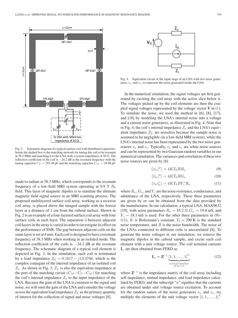
Fig. 3. Schematic diagram of a typical surface coil with distributed capacitors.Inside the dashed box is the matching network for tuning the coil to be resonantat 38.3 MHz and matching it to the LNA with a system impedance of 50 Ω. Thereflection coefficient of the coil is −24.2 dB at the resonant frequency with thetuning capacitor CT = 293.48 pF and the matching capacitor CM = 18.08 pF.
made to radiate at 38.3 MHz, which corresponds to the resonantfrequency of a low-field MRI system operating at 0.9 T B0field. This layer of magnetic dipoles is to simulate the ultimatemagnetic field signal source in an MRI scanning process. Theproposed multilayered surface coil array, working as a receivercoil array, is placed above the imaged sample with the lowestlayer at a distance of 1 cm from the cuboid surface. Shown inFig. 2 is an example of a four-layered surface coil array with foursurface coils in each layer. The separation d between adjacentcoil layers in the array is varied in order to investigate its effect onthe performance of SNR. The gap between adjacent coils on thesame layer is set at 4 mm. Each coil is designed to have a resonantfrequency of 38.3 MHz when working in an isolated mode. Thereflection coefficient of the coils is −24.2 dB at the resonantfrequency. The schematic diagram of a typical coil element isdepicted in Fig. 3. In the simulation, each coil is terminatedby a load impedance ZL = 0.1617 − j13.3706, which is thecomplex conjugate of the internal impedance of an isolated coilZa . As shown in Fig. 3, ZL is also the equivalent impedance atthe port of the matching circuit (CM −CT −CM ) for matchingthe coil’s internal impedance Za to the input impedance of theLNA. Because the gain of the LNA is common to the signal andnoise, we will omit the gain of the LNA and consider the voltageacross the equivalent load impedance ZL as the primary quantityof interest for the collection of signal and noise voltages [8].
Fig. 4. Equivalent circuit of the input stage of an LNA with two noise gener-ators, vn and in , to represent the noise generated inside the LNA.
In the numerical simulation, the signal voltages are first gen-erated by exciting the coil array with the active slice below it.The voltages picked up by the coil elements are then the cou-pled signal voltages represented by the voltage vector V in (1).To simulate the noise, we used the method in [6], [8], [17],and [18] by modeling the LNA’s internal noise into a voltageand a current noise generators, as illustrated in Fig. 4. Note thatin Fig. 4, the coil’s internal impedance Za and the LNA’s equiv-alent impedance ZL are noiseless because the sample noise isassumed to be negligible (in a low-field MRI system), while theLNA’s internal noise has been represented by the two noise gen-erators vn and in . Typically, vn and in are white noise sourcesand can be represented by two Gaussian random variables in ournumerical simulation. The variances and correlation of these twonoise sources are given by [8]
〈|vn |2〉 = 4KT0BRn (9)
〈|in |2〉 = 4KT0BGn (10)
〈vn i∗n 〉 = 4KT0BY ∗γ Rn (11)
where Rn,Gn , and Yγ are the noise resistance, conductance, andadmittance of the LNA, respectively. These three parametersare given by or can be obtained from the data provided bythe manufacturer. In our calculation, a typical LNA, MAX9632[19], with noise parameters Rn = 55.2 Ω, Gn = 19.0 mS, andYγ = 18.1 mS is used. For the other three parameters in (9)–(11), K is Boltzmann’s constant, T0 = 290 K is the standardnoise temperature, and B is the noise bandwidth. The noise ofthe LNAs connected to different coils is uncorrelated [8]. Togenerate the noise voltages in our simulation, we remove themagnetic dipoles in the cuboid sample, and excite each coilelement with a unit voltage source. The coil terminal currentsIu are then obtained from FEKO as
Iu = Z−1 [1, 1, . . . , 1]T︸ ︷︷ ︸a total number
of m×n
(12)
where Z−1 is the impedance matrix of the coil array includingself-impedance, mutual impedance, and load impedance calcu-lated by FEKO, and the subscript “u” signifies that the currentsare obtained under unit voltage source excitation. To accountfor the random nature of the noise generators vn and in , wemultiply the elements of the unit voltage vector [1, 1, . . . , 1]T

760 IEEE JOURNAL OF BIOMEDICAL AND HEALTH INFORMATICS, VOL. 17, NO. 3, MAY 2013
on the right-hand side of (12) by m × n noise generators eachwith two Gaussian random variables (vn and in ) in the form ofvn + inZL , and the random noise voltages [N in (2)] are thencalculated. For example, if we denote the current vector (underunit voltage excitation) for the jth stack of coil as
Iu j = [Iu 1j , Iu 2j , . . . , Iu ij , . . . , Iu mj ]T (13)
where Iu ij is the corresponding current element of coil ij in(12), then the corresponding random noise voltage vector of thejth stack is
Nj = ZL [(vn 1j +in 1jZL )Iu 1j , (vn 2j +in 2jZL )Iu 2j , . . .
(vn ij +in ijZL )Iu ij , . . . , (vn mj +in mjZL )Iu mj]T .
(14)
Since noise sources from LNAs connected to different coilsare uncorrelated [8], the noise correlation matrix for this stack⟨NjNH
j
⟩is obtained as (15), shown at the bottom of the page,
where Vu ij = ZLIu ij . Therefore, the coupled noise power forthe jth stack for the calculation of coupled SNRc
j by (8) can bewritten as⟨∣∣∣∣∣
m∑
i=1
Nij
∣∣∣∣∣
2⟩=
m∑
i=1
(⟨|vn ij + in ijZL |2
⟩|Vu ij |2
). (16)
The decoupled noise voltages can then be calculated by (7),and the decoupled noise power can be obtained.
B. Determination of the Decoupling Matrix T−1v
As mentioned in Section II, due to the strong mutual couplingeffect between the layers of coils in the multilayered coil array,a properly designed decoupling matrix T−1
v plays a crucial rolein determining the improvement in the SNR of the coil array.From the perspective of electromagnetic analysis, the elementsof T−1
v are the mutual impedances of the coil antennas. Morespecifically, these mutual impedances are the receiving mutualimpedance [20] as the array coils are in the receiving mode ofoperation. A standard procedure to determine the receiving mu-tual impedances for a two-element array was given in detailsin [21]. In our current study, we applied this method to each
TABLE ISNRS OF A SINGLE-LAYERED SURFACE COIL ARRAY UNDER THE DECOUPLING
MATRIX METHOD
pair of coils in the array so that all the elements of the decou-pling matrix T−1
v are determined. The effectiveness of using thereceiving mutual impedances (the elements of T−1
v ) to removethe mutual coupling effect has been demonstrated in many pre-vious studies before, for example, [3], [5], [6] and [22], so itis not repeated in this study. In the next ection, we illustratehow the so-determined decoupling matrix for the multilayeredsurface coil array is used to obtain an improved SNR from thedecoupled signal voltages.
C. SNR Performance of the Multilayered Surface Coil Array
Before the SNR performance of the multilayered surface coilarray is investigated, we demonstrate the SNR performance ofa single-layered surface coil first. In this special case, we cancompare the SNR performance under two different decouplingmethods, the decoupling matrix method and the commonly usedoverlapping method [2]. In the decoupling matrix method, thedecoupling matrix T−1
v for a single-layered surface coil arraywhich has four coil elements (coil 11, coil 12, coil 13, and coil14) is first determined as (17), shown at the bottom of the page.
The SNRs in (6) and (8) are then calculated and they areshown in Table I. Note that the values in Table I are calculatedbased on the setting to make the SNR for a single isolatedcoil be 20 dB. We can see from Table I that the values ofSNRd
j for the coils (the SNRs calculated with the decoupledvoltages) are almost the same as the SNR for an isolated coil.(The slightly larger values of SNRd
j than the isolated SNR aredue to the slightly reduced noise power after the decouplingprocess when compared with the noise power of an isolatedcoil.) This indicates that the mutual coupling effect is almostcompletely removed. It is shown more directly when they arecompared with SNRc
j of the coils in the bottom row of Table I,which are much smaller (approximately 20 dB down), indicating
⟨NjNH
j
⟩
=
⎡
⎢⎢⎢⎢⎢⎣
⟨|vn 1j + in 1jZL |2
⟩|Vu 1j |2 0 · · · 0
0⟨|vn 2j + in 2jZL |2
⟩|Vu 2j |2 · · · 0
......
. . ....
0 0 · · ·⟨|vn mj + in mjZL |2
⟩|Vu mj |2
⎤
⎥⎥⎥⎥⎥⎦(15)
T−1v =
⎡
⎢⎣
1 5.23 − j18.59 0.59 − j1.01 0.22 − j0.280.10 − j14.49 1 0.26 − j14.50 0.23 − j0.790.24 − j0.78 0.52 − j14.48 1 0.36 − j14.470.22 − j0.24 0.60 − j0.93 5.75 − j18.22 1
⎤
⎥⎦ . (17)
LIANG et al.: IMPROVED SIGNAL-TO-NOISE RATIO PERFORMANCE IN MAGNETIC RESONANCE IMAGING 761
TABLE IISNRS OF A SINGLE-LAYERED SURFACE COIL ARRAY UNDER THE
OVERLAPPING DECOUPLING METHOD
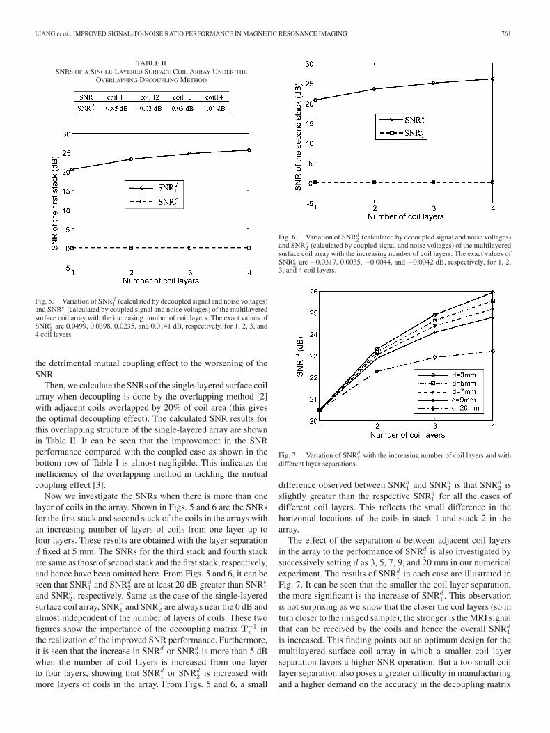
Fig. 5. Variation of SNRd1 (calculated by decoupled signal and noise voltages)
and SNRc1 (calculated by coupled signal and noise voltages) of the multilayered
surface coil array with the increasing number of coil layers. The exact values ofSNRc
1 are 0.0499, 0.0398, 0.0235, and 0.0141 dB, respectively, for 1, 2, 3, and4 coil layers.
the detrimental mutual coupling effect to the worsening of theSNR.
Then, we calculate the SNRs of the single-layered surface coilarray when decoupling is done by the overlapping method [2]with adjacent coils overlapped by 20% of coil area (this givesthe optimal decoupling effect). The calculated SNR results forthis overlapping structure of the single-layered array are shownin Table II. It can be seen that the improvement in the SNRperformance compared with the coupled case as shown in thebottom row of Table I is almost negligible. This indicates theinefficiency of the overlapping method in tackling the mutualcoupling effect [3].
Now we investigate the SNRs when there is more than onelayer of coils in the array. Shown in Figs. 5 and 6 are the SNRsfor the first stack and second stack of the coils in the arrays withan increasing number of layers of coils from one layer up tofour layers. These results are obtained with the layer separationd fixed at 5 mm. The SNRs for the third stack and fourth stackare same as those of second stack and the first stack, respectively,and hence have been omitted here. From Figs. 5 and 6, it can beseen that SNRd
1 and SNRd2 are at least 20 dB greater than SNRc
1and SNRc
2 , respectively. Same as the case of the single-layeredsurface coil array, SNRc
1 and SNRc2 are always near the 0 dB and
almost independent of the number of layers of coils. These twofigures show the importance of the decoupling matrix T−1
v inthe realization of the improved SNR performance. Furthermore,it is seen that the increase in SNRd
1 or SNRd2 is more than 5 dB
when the number of coil layers is increased from one layerto four layers, showing that SNRd
1 or SNRd2 is increased with
more layers of coils in the array. From Figs. 5 and 6, a small
Fig. 6. Variation of SNRd2 (calculated by decoupled signal and noise voltages)
and SNRc2 (calculated by coupled signal and noise voltages) of the multilayered
surface coil array with the increasing number of coil layers. The exact values ofSNRc
2 are −0.0317, 0.0035, −0.0044, and −0.0042 dB, respectively, for 1, 2,3, and 4 coil layers.
Fig. 7. Variation of SNRd1 with the increasing number of coil layers and with
different layer separations.
difference observed between SNRd1 and SNRd
2 is that SNRd2 is
slightly greater than the respective SNRd1 for all the cases of
different coil layers. This reflects the small difference in thehorizontal locations of the coils in stack 1 and stack 2 in thearray.
The effect of the separation d between adjacent coil layersin the array to the performance of SNRd
j is also investigated bysuccessively setting d as 3, 5, 7, 9, and 20 mm in our numericalexperiment. The results of SNRd
1 in each case are illustrated inFig. 7. It can be seen that the smaller the coil layer separation,the more significant is the increase of SNRd
1 . This observationis not surprising as we know that the closer the coil layers (so inturn closer to the imaged sample), the stronger is the MRI signalthat can be received by the coils and hence the overall SNRd
1is increased. This finding points out an optimum design for themultilayered surface coil array in which a smaller coil layerseparation favors a higher SNR operation. But a too small coillayer separation also poses a greater difficulty in manufacturingand a higher demand on the accuracy in the decoupling matrix

762 IEEE JOURNAL OF BIOMEDICAL AND HEALTH INFORMATICS, VOL. 17, NO. 3, MAY 2013
realization. From Fig. 7, it can be noticed that the increase ofSNRd
1 becomes smaller as the number of coil layers increases.The reason for this is that the additional top coil layers areactually positioned farther away from the sample and hencethe power picked up by them becomes smaller compared tothat of the bottom coil layers. This makes the contribution ofthe added coil layers to the SNR improvement become smaller(more detailed explanations can be found in [6]).
IV. CONCLUSION
A multilayered surface coil array for MRI is presented and itsimproved SNR performance is demonstrated through a rigoroussimulation study. By using an effective decoupling method, thedetrimental mutual coupling effect in the array is accuratelyremoved. This enables the individual coil signals to be summedup coherently, leading to an SNR improvement with the numberof coil layers in the array. It is shown that a more than 5 dBincrease in SNR can be obtained with a four-layered array. Thistheoretical study and the simulation results have demonstrateda potentially low-cost method to tackle the low SNR issue inMRI systems, especially in low-field MRI systems.
REFERENCES
[1] J. M. Jin, Electromagnetic Analysis and Design in Magnetic ResonanceImaging. Boca Raton, FL, USA: CRC Press, 1999.
[2] P. B. Roemer, W. A. Edelstein, C. E. Hayes, S. P Souza, andO. M. Mueller, “The NMR phased-array,” Magn. Reson. Med., vol. 16,no. 2, pp. 192–225, 1990.
[3] H. T. Hui, “An effective compensation method for the mutual couplingeffect in phased arrays for magnetic resonance imaging,” IEEE Trans.Antennas Propag., vol. 53, no. 11, pp. 3576–3583, Nov. 2005.
[4] M. A. Ohliger, P. Ledden, C. A. McKenzie, and D. K. Sodickson, “Ef-fects of inductive coupling on parallel MR image reconstructions,” Magn.Reson. Med., vol. 52, no. 3, pp. 628–639, 2004.
[5] D. Liang, H. T. Hui, T. S. Yeo, and B. K. Li, “Stacked phased array coilsfor increasing the signal-to-noise ratio in magnetic resonance imaging,”IEEE Trans. Biomed. Circuits Syst., vol. 7, no. 1, pp. 24–30, Feb. 2013.
[6] D. Liang, H. T. Hui, and T. S. Yeo, “Increasing the signal-to-noise ra-tio by using vertically stacked phased array coils for low-field magneticresonance imaging,” IEEE Trans. Inf. Technol. Biomed., vol. 16, no. 6,pp. 1150–1156, Nov. 2012.
[7] R. T. Compton, Adaptive Antennas, Concepts and Performance. Engle-wood Cliffs, NJ, USA: Prentice-Hall, 1988.
[8] C. Craeye, B. Parvais, and X. Dardenne, “MOM simulation of signal-to-noise patterns in infinite and finite receiving antenna arrays,” IEEE Trans.Antennas Propag., vol. 52, no. 12, pp. 3245–3256, Dec. 2004.
[9] K. H. Lee, M. C. Cheng, K. K. Wong, S. S. M. Yeung, K. C. Lee, Q. Y. Ma,and E. S. Yang, “Performance of large-size superconducting coil in 0.21 TMRI system,” IEEE Trans. Biomed. Eng., vol. 51, no. 11, pp. 2024–2030,Nov. 2004.
[10] Y. Li, Y. Guo, and X. Jiang, “Signal-to-noise ratio improvement by Bi-2223 surface RF coil in 0.3 T MRI system,” IEEE Trans. Appl. Supercon.,vol. 20, no. 3, pp. 818–821, Jun. 2010.
[11] L. L. Tsai, R. W. Mair, M. S. Rosen, S. Patz, and R. L. Walsworth, “Anopen-access, very-low-field MRI System for posture-dependent 3 He hu-man lung imaging,” J. Magn. Reson., vol. 193, no. 2, pp. 274–285, Aug.2008.
[12] M. D. Harpen, “Sample noise with circular surface coils,” Med. Phys.,vol. 14, no. 4, pp. 616–618, 1987.
[13] I. J. Gupta and A. A. Ksienski, “Effect of mutual coupling on the perfor-mance of adaptive arrays,” IEEE Trans. Antennas Propag., vol. AP–31,no. 5, pp. 785–791, Sep. 1983.
[14] Q. Yuan, Q. Chen, and K. Sawaya, “Performance of adaptive array antennawith arbitrary geometry in the presence of mutual coupling,” IEEE Trans.Antennas Propag., vol. 54, no. 7, pp. 1991–1996, Jul. 2006.
[15] G. R. Duensing, H. R. Brooker, and J. R. Fitzsimmons, “Maximizingsignal-to-noise ratio in the presence of coil coupling,” J. Magn. Reson.,Series B, vol. 111, pp. 230–235, 1996.
[16] (2011). [Online]. Available: http://www.feko.info/[17] A. Kisliansky, R. Shavit, and J. Tabrikian, “Direction of arrival estimation
in the presence of noise coupling in antenna arrays,” IEEE Trans. AntennasPropag., vol. 55, no. 7, pp. 1940–1947, Jul. 2007.
[18] J. Engberg and T. Larsen, Noise Theory of Linear and Nonlinear Circuits.Chichester, U.K.: Wiley, 1995, pp. 41–45.
[19] MAX9632 datasheet, [Online]. Available: http://www.maxim-ic.com/datasheet/index.mvp/id/6606
[20] H. T. Hui, H. P. Low, T. T. Zhang, and Y. L. Lu, “Receiving mutualimpedance between two normal mode helical antennas (NMHAs),” IEEEAntenna Propag. Mag., vol. 48, no. 4, pp. 92–96, Aug. 2006.
[21] H. T. Hui, “A new definition of mutual impedance for application in dipolereceiving antenna arrays,” IEEE Antenna Wireless Propag. Lett., vol. 3,no. 1, pp. 364–367, Dec. 2004.
[22] H. T. Hui, B. K. Li, and S. Crozier, “A new decoupling method for quadra-ture coils in magnetic resonance imaging,” IEEE Trans. Biomed. Eng.,vol. 53, no. 10, pp. 2114–2116, Oct. 2006.
Dandan Liang received the B.Eng. degree in elec-tronic engineering from Xidian University, Shaanxi,China, in 2006. She is currently working toward thePh.D. degree in electrical and computer engineeringfrom the National University of Singapore (NUS),Singapore.
In July 2008, she joined the Department of Elec-trical and Computer Engineering, NUS as a ResearchScholar. Her current research interest includes themedical application of bioelectromagnetics
Hon Tat Hui (SM’04) received the B.Eng. (Hons.)degree with first class honors from the City Univer-sity of Hong Kong, Kowloon, Hong Kong, in 1994,and the Ph.D. degree from The City University ofHong Kong, in 1998.
From 1998 to 2001, he was a Research Fellowin the City University of Hong Kong. From 2001 to2004, he was an Assistant Professor in the NanyangTechnological University in Singapore. From 2004 to2007, he was a Lecturer in the School of InformationTechnology and Electrical Engineering, University
of Queensland. He is currently an Assistant Professor with the Department ofElectrical and Computer Engineering, National University of Singapore. He haspublished more than 70 papers in internationally refereed journals. His researchinterest is in the use of antennas for biomedical applications.
Dr. Hui has been a Project Reviewer of various industrial and governmentorganizations. He was the exceptional performance reviewer for the IEEE An-tennas and Propagation Society in 2008 and 2009. He served as an editorialboard member in various international journals. He has helped organize manylocal and international conferences.
Tat Soon Yeo (M’79–SM’93–F’03) received theB.Eng. (Hons. I) and M.Eng. degrees from the Na-tional University of Singapore (NUS), Singapore,in 1979 and 1981, respectively, and the Ph.D. de-gree from the University of Canterbury, Christchurch,New Zealand, under a Colombo Plan Scholarship in1985.
He is currently a Professor in the Departmentof Electrical and Computer Engineering and a ViceDean of the Faculty of Engineering, NUS. He is alsoconcurrently the Director of Radar and Signal Pro-
cessing Laboratory, and Antennas and Propagation Laboratory in the Depart-ment of Electrical Engineering, NUS. He is also the Director of Temasek De-fence Systems Institute, a teaching institute established jointly by NUS andU.S. Naval Postgraduate School. His current research interests include scatter-ing analysis, synthetic aperture radar, antenna and propagation study, numericalmethods in electromagnetics, and electromagnetic compatibility.
Dr. Yeo received the Singapore Ministry of Defence–National Universityof Singapore 1997 Joint R&D Award, the IEEE Millennium Medal in 2000,and the Singapore Standard Council’s Distinguish Award in 2002. He is theEx-Chairman and Executive Committee Member of the MTT/AP and EMCChapters, IEEE Singapore Section, and the Chairman of Singapore EMC Tech-nical Committee.