improvement of aircraft mechanical damage inspection … · aircraft must be inspected to ensure...
TRANSCRIPT

Improvement of aircraft mechanical damage inspection with advanced
3D imaging technologies
Pierre-Hugues ALLARD, Jérôme-Alexandre LAVOIE, Jean-Simon FRASER
CREAFORM
5825 rue St-Georges, Lévis (QC), Canada, G6V 4L2; Phone: 1-418-833-4446 E-mail: [email protected]
[email protected], [email protected]
Abstract
Mechanical damage on aircraft fuselage, wings and landing gear can be caused by hail damage or various types of impact on the ground. Regardless of their origin, impacts on aircraft must be inspected to ensure conformity with manufacturer requirements. Manual inspection techniques are still being used to approximate impacts maximum depth, dimensions and position, although they prove to be highly dependent on the inspector skills. 3D imaging technologies used for years in the metrology industry can be applied to improve accuracy, repeatability and inspection speed for this application. The objective is to minimize aircraft down time during inspection with fast decision making made possible with on-site results. This new approach to aircraft mechanical damage inspection will be described and inspection results will be presented.
1. Hail Damage Assessment 1.1 3D laser scanner The Handyscan3D, manufactured by Creaform, is a portable 3D laser scanner used to accurately map the surface of a free form object regardless of the material. A laser cross is projected on the surface while two cameras read the laser cross profile to build a 3D scan file (mesh) in real time. The scanner is self-positioned by triangulation of randomly positioned reflective targets. This non-contact inspection technique eliminates the need to mechanically fix the scanner to the scanned object. The accuracy is up to 40 microns in any work environment by using a dynamic referencing system called TRUaccuracy.
Figure 1: Handyscan3D laser scanner
5th International Symposium on NDT in Aerospace, 13-15th November 2013, Singapore

The total accuracy of the system is the punctual accuracy in addition to the volumetric accuracy per meter of scan. The accuracy for a 3D laser scanner is defined as the maximum deviation in a spherical radius around the nominal point value. The volumetric accuracy is the stacking error per meter of linear scan induced by the positioning system or maximum cumulative errors of measurements over a distance. The term accuracy is intrinsic to the scanner design and is not related to the scan resolution for a 3D scanner. The data points in a mesh file are linked together to form an organized pattern of triangles of equal size. Each vertex has the specified accuracy. Resolution is a parameter input specified by the inspector to define the size of the triangles used to build a 3D mesh file. A typical mesh file scan is shown in figure 2.
Figure 2: 3D mesh file in STL format
Analysis of 3D mesh files The laser scanner allows a complete coverage of the damaged area in 3D allowing any measurement to be taken from the outside surface. The raw data is a mesh file saved in STL file format in VxElements data collection software and is available for future assessments and audits. In order to characterize defects on airplane fuselages, a reference surface must be created to recreate a localized nominal surface as if there were no defects. There are three ways to generate a nominal reference surface. The first one consists in comparing the scan to the original CAD model. However, the CAD model for components under maintenance is rarely available and can present deviations from the actual geometry. A second method is to create in post-treatment software a theoretical geometry approximating the object initial geometry. The third and most accurate method is to reconstruct a surface based on a free-form model best-fitted to the real component geometry.

Figure 3: Creation of a reference surface in Polyworks analysis software
In the case of impact or wear assessment on airplanes, Polyworks post-treatment software is used to create a proper reference surface and compare it to the 3D scan file to measure deviations, as shown in figure 3.
1.2 Hail Damage analysis and reporting
Hail damage inspection requires to find the deepest point in the dent, find the maximum length and the width at 90 degrees with respect to the maximum length, determine the minimum distance between the dents, and determine the position with respect to a given rivet line or fuselage section. Those values will be compared against the airplane manufacturer specifications for decision making on repairs.
The first step consists in applying reflective targets locally around the impact. Once the damaged area is acquired with the 3D scanner, the STL file is imported into post-treatment software for analysis. The reference surface is created and compared to the 3D scan file. A macro specifically programmed for this application can be used to obtain all required measurements automatically. The report can be quickly generated from a predefined report template in PDF format.
Figure 4: 3D colormap of 7 impacts on fuselage

In the case where multiple dents are found in the same area, interaction between dents must be verified by measuring the minimum distance between dents.
Figure 5: Minimum distance measured between dents to validate interaction
The profile of each dent can be visualized and measured using 2D cross sections in both axes. Whiskers are used to facilitate visualisation of defect amplitude with the customable color scale. Fail criteria can be defined to automatically reject dents with depth exceeding a threshold specified by the inspector.
Figure 6: 2D cross section on one dent
This technique replaces pit gauge technique by allowing repeatable and accurate measurements to be taken. It eliminates the impact of inspector skills during data collection and greatly minimizes airplane downtime.

2. Case study: in-flight damage on Qantas Airbus 380
On November 4th 2010, a Qantas airline A380 connecting London UK to Sydney Australia had to proceed with emergency landing in Singapore because of a problem on one of the four engines.
One of the blade on engine #2 broke and damaged the protection carter and left wing. The objective for this inspection is to quantify wing damage and compare to traditional methods. In this case, a combination of 3D laser scanning and photogrammetry was used to properly characterize damage and secondary effects on the wing structure.
Figure 7: Picture of wing damage during flight
Figure 8: Wing damage caused by engine failure

Figure 9: Inspector scanning the damaged wing section with the laser scanner
The first step was to ensure very high precision for the 3D laser inspection on the wing so photogrammetry was used to increase the positioning model accuracy. The MAXshot manufactured by Creaform is used as a complement to the Handyscan3D to take picture of the positioning model with scale bars and therefore bring down the accuracy to 0.020mm + 0.025mm per meter of scan. Once the referencing model is acquired, the 3D laser scan is then performed around the damaged area to generate a 3D scan file. This procedure is only required for the scan of large objects such as an Airbus 380 wing.
Figure 10: 3D scan of wing damage

The client wanted to assess the wing deformation caused by the impact. From the 3D scan file of the wing section, the local deformation was measured and represented in picture 11 in a blue scale color.
Figure 11: Characterization of wing deformation around the defect
The fuel tank structure inside the wing was suspected to be deformed following the impact and had to be inspected. The same scanner and methodology was used to obtain a 3D scan of the fuel tank which was then compared to a CAD file representing the nominal shape. Figure 12 shows the fuel tank deformation caused by the impact on the wing.
Figure 12: Scan of fuel tank inside the wing to measure deformations
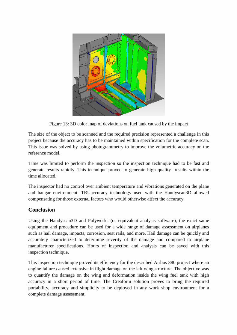
Figure 13: 3D color map of deviations on fuel tank caused by the impact
The size of the object to be scanned and the required precision represented a challenge in this project because the accuracy has to be maintained within specification for the complete scan. This issue was solved by using photogrammetry to improve the volumetric accuracy on the reference model.
Time was limited to perform the inspection so the inspection technique had to be fast and generate results rapidly. This technique proved to generate high quality results within the time allocated.
The inspector had no control over ambient temperature and vibrations generated on the plane and hangar environment. TRUaccuracy technology used with the Handyscan3D allowed compensating for those external factors who would otherwise affect the accuracy.
Conclusion
Using the Handyscan3D and Polyworks (or equivalent analysis software), the exact same equipment and procedure can be used for a wide range of damage assessment on airplanes such as hail damage, impacts, corrosion, seat rails, and more. Hail damage can be quickly and accurately characterized to determine severity of the damage and compared to airplane manufacturer specifications. Hours of inspection and analysis can be saved with this inspection technique.
This inspection technique proved its efficiency for the described Airbus 380 project where an engine failure caused extensive in flight damage on the left wing structure. The objective was to quantify the damage on the wing and deformation inside the wing fuel tank with high accuracy in a short period of time. The Creaform solution proves to bring the required portability, accuracy and simplicity to be deployed in any work shop environment for a complete damage assessment.