improvement of hand pump design water for the rural areas, but their inputs are relatively small....
TRANSCRIPT

2 3 2 . 2
' - 7 8 I M i .
KINGDOM OF THAILAND
MINISTRY OF INTERIOR
ACCELERATED RURAL DEVELOPMENT OFFICE
IMPROVEMENT OF HAND PUMP DESIGN IN
THAILAND
Equipment Control Division
PUBLISHED UNDER THE SPONSORSHIP OF
°N,c** THE UNITED NATIONS CHILDREN'S FUND

2-32.2-}3/M
U KINGDOM OF THAILAND
MINISTRY OF INTERIOR
ACCELERATED RURAL DEVELOPMENT OFFICE
IMPROVEMENT OF HAND PUMP DESIGN IN THAILAND
LIBRARY
international iaferonce Csni?a few Community Water Supply
Equipment Control Division
PUBLISHED UNDER THE SPONSORSHIP OF
THE UNITED NATIONS CHILDREN'S FUND

CONTENTS
PREFACE 1
1. INTRODUCTION 3
1.1 Background Information 3
1.2 Problem Identification 6
2. OBJECTIVE OF PROJECT 8
3. PROGRAMME OF WORK OF PROJECT 9
3.1 Deep Well Selection 9
3.2 Deep Well Classification 11
3.3 Preparation of Data Collection Forms 11
3.4 Hand Pump Installation 12
3.5 Data Collection 13
3.6 Data Analysis 16
3.7 Hand Pump Improvement 17
3.8 Installation of New Improved Hand Pumps 18
3.9 Monitoring of Improved Hand Pump Operation 18
3.10 Evaluation and Report 18
4. SUMMARY AND ANALYSIS OF THE BASIC DATA 19
4.1 Water Utilization 20
4.2 Hand Pump Operation 22
4.3 Hand Pump Capability 24
4.4 Deterioration and Damages of Hand Pumps 29

5. IMPROVEMENT OF HAND PUMP DESIGN 32
5.1 Hand Pump Improvement 32
5.2 Data Collection and Analysis after 34
Installation of Improved Hand Pump
5
6. RECOMMENDATIONS 35
6.1 Improvement of Hand Pump 35
6.2 Hand Pump Programme 36
7. CONCLUSION 43
APPENDIX A CHARACTERISTICS OF HAND PUMPS 45
CURRENTLY IN USED IN THAILAND
APPENDIX B COMPARISON BETWEEN OLD AND IMPROVED 52
HAND PUMPS
APPENDIX C DATA COLLECTION FORMS 86
APPENDIX D REVISED PARTS DRAWING 92
APPENDIX E WORKING GROUP AND ACKNOWLEDGEMENT 131
REFERENCES 134
1
PREFACE
Village water supply is one of the most important problems in developing
countries, especially in Thailand where more than 80 percent of the population
- live in rural villages. While people in municipal areas have been enjoying
benefits from good quality water supply, supplies in rural communities have
been far from adequate.
In general, potable (drinking) water and water used for other ,domestic
purposes may be obtained from various sources including rain water, deep
wells, shallow wells, ponds, reservoirs, rivers and canals. Of all these
souices, deep well water is regarded as not only the safest water from
waterborne diseases but also the highly economical source which can be
rapidly developed for a given community.
In the effort to develop village water supply, more than 10,000 deep
wells have been drilled and developed in Thailand up to the present time.
Under the government's policy, not less than 1,000 deep wells have been
drilled all over the country each year, and different government agencies
are responsible for maintenance of these wells, including the Department
of Mineral Resources, the Ministry of Industry; the Department of Health,
the Public Health Ministry; the Office of Accelerated Rural Development
and the Department of Public Works, the Ministry of Interior.
Records have shown that more than 90 percent of the existing wells
in Thailand have been installed with hand pumps which are used as a means
to lift water from these wells. In total, about 5 million rural Thai people
have to depend upon these hand pumps to obtain water for drinking and other
domestic purposes. While hand pumps have become an essential part of the
daily life of these rural people, operation and maintenance of the pumps
have also become persistent problems needed to be solved. Having realized
such problems, the Office of Accelerated Rural Development, with a financial
aid from UNICEF, took an initiative to conduct a hand pump testing and
evaluation programme to be used as a basis for improvement of hand pump design.

2
Concurrent with this study, a study on shallow well hand pumps made
of PVC material is being undertaken by the Department of Health. Additionally,
Asian Institute of Technology will carry out a research on design and develop
ment of a typical hand pump which will be utilized in Thai rural communities
in the future. The main emphasis of this study is placed on revision and
improvement of the design of existing hand pumps, particulary the deep well
reciprocating pump ( cylinder submerged in water ) so as to resolve current
problems of hand pump maintenance to the maximum extent possible.

3
HAND PUMP EVALUATION AMD TESTING IN THAILAND
FOR IMPROVEMENT OF HAND PUMP DESIGN
1. Introduct ion
1.1 Background Information
The prov i s ion of c lean water for rura l areas in Thailand was
i n i t i a t e d in 1964. In the fo l lowing year , the cabinet appointed an
execut ive committee on t h i s matter c o n s i s u j i g of the members from
various departments, and i t s r e s p o n s i b i l i t i e s were planning and
execut ion of the National Rural Water Supply Programme. The taxget
of the programme was then s e t up t o implement a plan t o supply c lean
water t o l o c a l inhabi tants in some 50,000 v i l l a g e s throughout the
country, by employing severa l means inc lud ing:
(1) Shallow dug w e l l s and j e t w e l l s equipped with
hand pumps.
(2) Small diameter w e l l s equipped wi th hand pumps.
(3) Deep w e l l s equipped with hand pumps.
(4) Piped water supply.
(5) Rainwater c o l l e c t i o n tanks .
(6) Standard ponds.
(7) Improvement of e x i s t i n g ponds.
(8) Dikes and r e s e r v o i r s .
The f i r s t phase of the plan was t o provide c l ean water t o rural
inhabitants in 2 0 , 0 0 0 v i l l a g e s wi th in 6 y e a r s , from 1966 t o 1971, the
l a t t e r being t h e year when the Second Nat ional Economic and S o c i a l
Development Plan ended. The second phase of the progranme was then
included in t h e Third National Economic and S o c i a l Development Plan,
with the t a r g e t t o provide c lean water t o t h e remaining 20 ,000 v i l l a g e s
during the years 1972-1976. At the end of the Third Plan, the National
Economic and Soc ia l Development Board made a request t o the National

4
Institute of Development Administration (NIDA) for carrying out the
evaluation of the program. Results showed that only 9.3 percent of
rural population obtained water which is considered clean. In addition,
it was reported that there had been several problems and obstracles
prohibiting the project to reach its goal, and one of the causative
factors was found to be the failure of hand pump operation.
At the national level, the responsibility for providing clean
water is shared by several agencies as follows:-
(a) Department of Local Administration (DQLA)
This Department provides c l ean water t o small communities
through various a c t i v i t i e s including p r o v i s i o n of various types
of rainwater c o l l e c t i o n tanks , improvement of e x i s t i n g ponds,
and ass 1stant ing in cons truct ion of sha l low dug w e l l s and j e t
w e l l s equipped with hand pumps i n s t a l l e d by l o c a l people and
l o c a l contractors - At the end of 1977, a t o t a l of 32,410
shallow dug w e l l s and j e t w e l l s had been constructed . Of t h i s
t o t a l number, 5,820 w e l l s were i n s t a l l e d with the hand pump.
According t o the survey conducted by NIDA in the Northeastern
region, i t appeared that as high as 3 4 . 7 percent of the hand pumps
were inoperat ive during the i n v e s t i g a t i o n per iod.
(b) Department of Mineral Resources (DMR)
The Groundwater D i v i s i o n of the DMR provides c lean water t o
rural people by means of deep w e l l s . The depth of the w e l l s
var i e s from 100 f e e t t o 350 f e e t , with an average depth of 185
f e e t . At the end of 1977^ t h i s Department had d r i l l e d 7 ,798 deep
w e l l s a l l over the country, of which 9 2 . 3 percent of these w e l l s
were equipped with hand pumps and the r e s t wi th motor pumps. NIDA
reported that 18 .6 percent of the hand pumps i n s t a l l e d by t h i s
Department was out of operat ion during t h e survey undertaken in
• the Northeastern reg ion . Under the present plan, Department's
targe t i s t o construct 1,200 deep w e l l s annually .

5
Office of Accelerated Rural Development (ARD)
This Office was e s tab l i shed with the p r i n c i p a l po l i cy t o
acce l era te the development in underserved areas which are now
covering 53 provinces . I t s main tasks are t o construct access
roads l inking v i l l a g e s in remote areas t o d i s t r i c t and t o provide
c lean water in the underserved areas through construct ion of deep
w e l l s , shal low w e l l s and standard ponds as w e l l as improvement of
e x i s t i n g ponds. At the end of 1977, 2 ,376 deep w e l l s and 1,891
shallow w e l l s equipped with hand pumps had been constructed. It
was reported that 2 6 . 3 percent of these hand pumps were out of
operation during the survey undertaken by NIDA. Under the World
Bank Loan Project from 1977-1981, the ARD plans t o construct
3 ,500 deep w e l l s and 520 shallow w e l l s t o be equipped with hand
pumps.
Department of Public Works (DPW)
The Prov inc ia l Water Supply D i v i s i o n of t h i s Department i s
a l s o re spons ib l e for construct ion of deep w e l l s t o serve people
in rural areas in a l l reg ions expect the Northeastern reg ion.
Up t o the present t ime, 1,971 deep w e l l s have been constructed.
However, the data on number of broken hand pumps are not a v a i l a b l e .
Under the current plan, targe t of t h i s Department i s t o construct
200 deep w e l l s each year .
Department of Health (DH)
The Department of Health has been providing piped water
s i n c e 1966, through the nat iona l budget, community p a r t i c i p a t i o n ,
and contr ibut ion from in ternat iona l a g e n c i e s . From 1966-1977,
539 piped water schemes have been constructed serv ing 1 ,438 ,100
rural inhab i tant s , which i s a small port ion when compared with
the country's t o t a l rural populat ion. The Department of Health
r e a l i z e d t h a t , in order t o provide more c l e a n water, a new approach
must be considered. As a r e s u l t , the small diameter w e l l programme
for the communities of 500-1,500 people was introduced in 1976,
6
with the UNICEF assistance. As of September 1978, 130 small
diameter wells equipped with hand pumps have been contructed,
and there is a plan to construct 350 small diameter wells
equipped with hand pumps annually.
There are also other agencies involved in the provision of
clean water for the rural areas, but their inputs are relatively small.
Hand pumps utilized by these agencies are of different prototypes.
The five types of hand pumps which are widely used include: the Mineral
Resource Department hand pump. Public Works Department hand pump,
Health Department hand pump (Korat hand pump), ARD hand pump, local
Administration Department hand pump. The Mineral Resources Department
hand pump and the Public Works Department hand pump are the same
prototype, and the Health Department, ARD and Local Administration
Department are the Korat hand pump. Details of these hand pump types
are given in Appendix A, and the Details Drawing are given in Volume
2 and 3.
Pr ob 1 em Ind ent if ic at ion
At present, about 19,000 hand pumps have been installed all over
the country by the government agencies mentioned previously. Based on
the random sampling survey conducted by NIDA, it is estimated that
roughly 5,000 hand pumps are out of operation in any given day. This
means that a wasteful capital investment for hand pump itself will be
approximately US$ 400,000 at a given time. Furthermore, the wells
equipped with inoperative hand pumps will also be out of operation,
and the capital Investment cost of the wells ranging from US$ 200-5,000
per well will also become worthless.
As a result of these inoperative hand pumps, the chance of supply
ing clean water to all rural communities will be lost. Moreover, a
great number of wells have been constructed with community participation,
in cash or un kind or both. Hence, villagers may view the loss of
service as evidence that their contribution was a poor investment,
thereby losing their regard for the operating agencies. In addition,

7
the operational fa i lure of water we l l s Will certa in ly induce psychological
e f f ec t s on the rural people, which may cause negative at t i tudes towards
the Government as a whols.
The major problems which have been ident i f ied t o be the causes
of fa i lure of hand pumps can be summarized as f o l l o w s : -
(1) There are too many dif ferent types of hand pumps ins ta l l ed
in rural communities. This r e su l t s in d i f f i c u l t i e s for the local
authorit ies as wel l as the v i l l a g e r s t o maintain a l l of them because
certain spare-parts of these pumps are not interchangeable.
(2) Hand pumps are not durable enough because of incompetent
hand pump design.
(3) Quality of products i s not good enough due t o poor manufacture-
ing quality control .
(4) Community part ic ipat ion in maintaining hand pumps i s
generally lacking.
(5) Some agencies have no maintenance uni t s and f a c i l l i t i e s of
th e i r own for maintaining the ins ta l led pumps. Although maintenance
units are avai lable at other agencies, the ir c a p a b i l i t i e s are insuf f ic ient
for servicing a l l the hand pumps which are in operation.
(6) There i s no e f f ec t i ve coordination of hand pump maintenance
programmes among operating agencies at the grass-root l e v e l .
(7) Most hand pumps are ins ta l led in remote areas which are far
from the responsible agencies, thereby making i t d i f f i c u l t for the
communities t o communicate with the agencies when maintenance problem
occur.
(8) Hand pump i s presently ins ta l led unproperly and not careful
enough, result ing in serveral defects and subsequent damages of the
pumps.
(9) The budget al located t o each agency for operating preventive
maintenance programmes is l imited and not adequate.
8
(10) Spare-parts are not available on provincial and loca l markets
due to shortage of manufacturers of these parts .
In summary, the fa i lure of hand pumps in the country i s generally
caused by poor hand pump design, lack of e f f e c t i v e maintenance s t r a t e
g i e s , lack of maintenance organization at a grass-root l e v e l , f inancial
constraint , and shortage of spare-part manufacturers.
In order t o soJtwe the problems mentioned above a s e r i e s of actions
have t o be taken and the improvement of hand pump design i s considered
t o be the matter of the f i r s t pr ior i ty . In This connection, the o f f i ce
of Accelerated Rural Development approached UNICEF for f inancial ass is tance
for the project of t es t ing and evaluation of various types of hand pumps
under f i e l d operations with the object ives as given below.
Objectives of Project
Specif ic object ives of the project are summarized as fol lows:
(1) To study actual u t i l i z a t i o n patterns of water obtained from
hand-pump-equipped deep we l l s .
(2) To study performance, damages, and maintenance problems of
various types of hand pumps which are being used in Thailand under
actual f i e ld condit ions.
(3) To improve i n s t a l l a t i o n , operation, maintenance, and repair
techniques for each type of the ex i s t ing hand pumps.
(4) To evaluated types of material used for the di f ferent types
of the ex i s t ing hand pumps and t o compare t h e i r c o s t s .
(5) To e s tab l i sh guidel ines for hand pump maintenance.
(6) To improve hand pump design so that the Improved hand pump w i l l
have the following character i s t i c s : (1) withstand vigorous operation,, ( l i )
operate e a s i l y , ( i i i ) perform consis tent ly with a considerable degree
of durability., ( iv ) can be maintained loca l ly , (v) has a low investment
cost , and (v > become more v e r s a t i l e in i t s usage.
9
3. Programme of Work of Project
In order that the experimentation could be carried out to serve
the objectives of the hand pump improvement project and to obtain
data required for developing guidelines for hand pump maintenance,
the project was divided into 10 major stages, (including(a) selection
of sample deep wells, (b) deep well classification, -(c) preparation
of data recording forms, (d) hand pump installation, (e) data collection,
(f) data analysis, (g) hand pump improvement, (h) installation of
improved hand pumps, (i) monitoring of improved pump operation, and
(j) evaluation and report).
The work schedule of this project is shown in Table 1. Details of
each stage ean be described as follows:
3.1 Deep Well Selection
The first stage of the project was to select deep wells for testing
which were specified to have the following characteristics:-
(1) The wells which are located in Northeastern region where the
majority of hand pumps were installed and the degree of water vhortage
is high and which are those considered to represent the wells existing
in the region.
(2) The wells from which people obtained large amounts of water
during most of the daytime in every day. The purpose was to test the
installed hand pumps under heavy operational loads so as to obtain
experimental data similar to those expected to be obtained under the
actual operating conditions, and these data would be used in improving
the pumps to make them applicable under various conditions.
(3) The wells which had different pumping levels ranging from
15 feet to more than 45 feet, in order to study their performance at
these pumping levels.

Table 1
Work Schedule for Study Project
Task
No.
a.
b.
c.
d.
e.
f.
g-
h.
i.
J-
Description
Selection of sample deep wells.
Deep wells cl.a»aif ication.
Preparation of data recording forms.
Installation of hand pumps.
Data collection.
Data analysis.
Improvement of hand pump.
Installation of improved hand pumps.
Monitoring of operation of new hand pumps.
Evaluation and report preparation.
Time Period
1977
J J A S 0 N D
1978
J i
F M A M J J A S 0 N D
1979
J

11
The t ime period requi red fo r t h i s s tage was 3 months, dur ing
which t h e survey was made of a t o t a l of 32 w e l l s , of which 20 we l l s
were se l ec t ed fo r i n s t a l l a t i o n of the hand pumps t o be t e s t ed .
Deep Well C l a s s i f i c a t i o n
The deep we l l s s e l ec t ed fo r pump t e s t i n g were c l a s s i f i e d i n to
5 groups according t o t h e i r pumping l e v e l s :
(1) Group 1: wi th pumping l e v e l s l e s s than IS f e e t ,
(2) Group 2 : with pumping l e v e l s between 16-25 f e e t ,
(3) Group 3 : with pumping l e v e l s between 26-35 f e e t ,
(4) Group 4 : with pumping l e v e l s between 36-45 f e e t , and
(5) Group 5: with pumping l e v e l s more than 45 f e e t .
The pumping l eve l of a hand pump i s def ined as t h e s t a t i c water
leve l plus t h e draw down water l eve l at a pumping r a t e of 5 g a l l o n s /
minute (gpm).
This s t age requi red approximately one month, mainly fo r reviewing
c h a r a c t e r i s t i c s of each deep wel l from i t s record . In add i t ion , mapping
of each se l ec t ed deep well was ca r r i ed ou t .
Preparat ion of Data Col lec t ion Forms
Data needed t o be co l l ec t ed were divided i n to 5 c a t e g o r i e s , and
the corresponding da ta c o l l e c t i o n forms were prepared, as fo l lows:
(1) The form for recording da i ly water u t i l i z a t i o n : D e t a i l s
included in t h i s form were r e l a t e d t o hand pump opera tors (or i n d i v i
duals who fetched water wi th t h e aid of hand pump) such as sex, age,
and data on hand pump opera t ion inc luding , number of opera t ing s t r o k e s ,
operat ing period in each day, and type of water used (see d e t a i l s in
Append ix Q Form Number C- l ) .
(2) The form for recording water u t i l i z a t i o n by each family:
S ign i f ican t d e t a i l s of t h i s form were the number of persons in each
family, volume of water used da i l y which was c l a s s i f i e d by type of
water used and water sources , and means of water acqu i s i t i on (see d e t a i l s
in Apperid-txC;Form Number C-2)

12
(3) The form for recording operating time: Data collected included
operating time of each operator, which was needed in analysing the
length of time an,operator had to wait before he could get water. This
would also help in determining the appropriate number of operators per
hand pump.(See details in Appendix C Form Number C-3)
(4) The form for recording data on the installation of the tested
pumps: Data required were details relating to installation of different
types of hand pumps, including the type of hand pump, length of time
needed for installation, static water level, and characteristics of
wells. (See details in Appendix C Form Number C-4)
(5) Repair report form: This form was used to gather such details
as the date when a damage occurred, the date of commencement of repair,
the date of completion, the total number of days needed for repair,
the cost of accessories, details of damages found outside the hand pump
before dismantling and of those found inside the pump after dismantling,
(see details in Appendix C Form Number C-5)
This stage required about one month during which training of
personnel assigned to the data collection task was carried out.
3.4 Hand Pump Installation
The purpose of the study was to investigate performance of the
different types of hand pumps, namely (i) that of the Mineral Resources
Departmoat, (ii) that of the Public Works Department, (iii) that of. the
ARD which is the Korat hand pump, (iv) that improvised by the ARD
Equipment Control Division (newly invented and never been tested before),
and (v) that which is available on market (shallow well hand pumps).
As mentioned in Section 3.2, five groups of deep wells were
selected for testing according to their pumping levels. Since the
t>pe of hand pump available on market is usually used for shallow
wells, four of these pumps were installed at the wells of Group 2
(with the pumping levels ranging from 26-35 feet). As for the other
types of hand pumps, four of each were installed as follows:
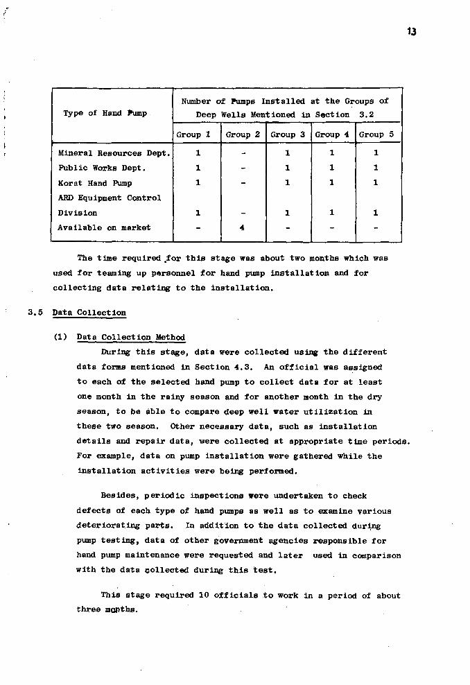
13
Type of Hand Pump
Mineral Resources Dept.
Public Works Dept.
Korat Hand Pump
ARD Equipment Control
Division
Available on market
Number of Pumps Installed at the Groups of
Deep Wells Mentioned in Section 3.2
Group 1
1
1
1
1
-
Group 2
-
-
-
-
4
Group 3
1
1
1
1
-
Group 4
1
1
1
1
-
Group 5
1
1
1
1
-
The time required .for this stage was about two months which was
used for teaming up personnel for hand pump installation and for
collecting data relating to the installation.
3.5 Data Collection
(1) Data Collection Method
During this stage, data were collected using the different
data forms mentioned in Section 4.3. An official was assigned
to each of the selected hand pump to collect data for at least
one month in the rainy season and for another month in the dry
season, to be able to compare deep well water utilization in
these two season. Other necessary data, such as installation
details and repair data, were collected at appropriate time periods.
For example, data on pump installation were gathered while the
installation activities were being performed.
Besides, periodic inspections were undertaken to check
defects of each type of hand pumps as well as to examine various
deteriorating parts. In addition to the data collected during
pump testing, data of other government agencies responsible for
hand pump maintenance were requested and later used in comparison
with the data collected during this test.
This stage required 10 officials to work in a period of about
three months.
14
(2) Measures Taken to Minimize Influence of Factors Affecting Hand
Pump Testing
The hand pump improvement project dealt primarily with field
testing operations with the major purpose of obtaining data which
are similar to those obtained under the actual operation of hand
pumps as possible. However, previous experiences have shown that
there* are several uncontrolable factors which would affect the
testing programme, and these can be described; as follows:
(a) Attitude of operators towards hand pumps: It has been
found that if villagers in a community have a good attitude towards
the hand pump, they will operate the hand pump carefully and would
not allow children to fool around with it. Additionally, they
would be aware of the fact that the hand pump given by government
should belong to the public or the village, thereby requiring their
own proper attention and maintenance. On the other hand, if
villagers have a negative attitude towards the pump, they will
operate the hand pump without a proper care. They would be pre
occupied with the idea that the hand pump still belongs to the
government and the government must be entirely and endlessly
responsible for its maintenance.
(b) Character of community leader: If the community leader is
a respectable person, such as a Buddhist monk or a village headman,
the operators (or water users) would be very careful in operating
the pump for fear of being reproached in case they cause any
_.._ damages to the pump.
(c) Importance of hand pump: If a hand pump is installed
at a community where deep well is the only water resource available,
the hand pump would be regarded as very important, and it would
receive good attention and care from villagers. On the contrary,
if other water resources are also available, the importance of
hand pump as a means of water acquisition would decrease.
(d) Education background: The education background of
villagers is also important to the project. In general, people
15
with a higher level of education would stand a better chance to
understand functions of the hand pump, and some may be able to
examine or even repair defective and/or worn out parts. This
would enable them to carry simple maintenence or minor adjustments
to prevent undue damages. As for villagers who have little
education, their capability in these aspects would also be little.
(e) Unity of village: Where the unity of a village is
strong, villagers will share their responsibility in hand pump
operation, and they may set up rules in using the hand pump by
which they abide to obtain effective use of the pump. Some may
even devote themselves to taking regular care of the pump.
(f) Tradition and culture of community; In most villages,
children and teenagers still pay respect to growns-up and the
eldery. In such villages, children are generally taught not to
fool around with the hand pumps, and damages to the pumps due to
children are not common.
(g) Hand pump location; If a hand pump is located at or
near the house of a respectable person of the community or in a
wat, villagers are likely to use water pump more carefully and
the children will not play near the pump. In addition, this
respectable person will usually look after and maintain the
hand pump himself.
(h) Number of government development projects in village:
These projects may deal with rural youth development, occupational
promotion, health development, and village water supply. Most of
these projects also need cooperation from the community headman.
In case there are too many projects in a village, the yillage
headman would be unlikely to pay adequate attention to all of
them. In case he disregards the importance of supply of domestic
and portable water,hand pump maintenance may be seriously affected.
(i) Operation of Local government agencies: Hand pump main
tenance wilj. be carried out successfully if the responsible government
agencies really pay attention to hand pump operation as well as
maintenance.
16
From past experiences, i t was expected during the
planning stage of t h i s study that the above-mentioned factors
would l i k e l y affect r e s u l t s of hand pump f i e l d t e s t i n g t o varying
degrees. Therefore, measures were taken during the study t o
decrease e f f ec t s of these factors t o the maximum extent- poss ib le ,
and these measured are describes as fol lows:
(a) There must be- no maintenance or adjustment of the
hand pump during the f i e l d t e s t .
(b) Vi l lagers were allowed t o used the hand pumps the
way they used t o do before th* t e s t i n g period began, even though
they did i t in an inappropriate or incorrect manner. Children
were not prohibited from playing near or at the hand pump.
(c) When any damages occurred during the f i e l d t e s t ,
the project o f f i c i a l must be informed and he was the only person
authorized t o maintain the pump.
3.6 Data Analysis
All data co l lected were analysed according t o the following types
of data:
(1) Data Relating to Water Ut i l i za t ion:
Analysis was made of number and type of v i l l a g e r s using
water with the aid of hand pump operation, purposes of water
u t i l i z a t i o n , and u t i l i z a t i o n of water obtained from other resources
as wel l as the type of v i l l a g e r s in t h i s category.
(2) Data Concerning Hand Pumps
These were a l l the data required for hand pump design and
improvement such as number of operating s trokes , hand pump per
formance, volume of water per stroke, and repair and maintenance
of di f ferent worn out parts of a l l types of hand pumps.
(3) Data Relating t o Application, Maintenance and Repair
These data comprised locat ions of the ins ta l l ed hand pumps
and persons who were in charge of hand pump operation.

17
3.7 Hand Pump Improvement
The major purpose of data collection and analysis for each type
of hand pump was to find an appropriate measure to improve the pump.
Redesign of worn out or defective parts, which depended on results
of this study, would be aimed at meeting the following requirements:
(1) The cost must not be much higher than the cost of the old
parts,
(2) Both repair and maintenance of the redesigned parts must be
easier than before, and maintenance should require less effort or
it should become virtually unnecessary,
(3) The new parts must be more durable and have longer life
than the old one if they are operated under the same conditions,
(4) The improved parts must be able to be manufactured locally
and/or available on the markets in provinces or districts, and the
materials used must also be locally available,
(5) The improved parts must be able to replace the corresponding
unimproved parts of each type of hand pump without a need for any
modifications of any irrelevant parts, 4
(6) The improvement must be compatible with character of operators,
characteristics of water, and must not create any hazards. Specifically
speaking, the following requirements must be met:
(i) Operating loads required must not exceed the capability
of most hand pump operators,
(ii) All parts must not be easily loosened or removable, in
order to prevent the parts from being removed as a toy or being taken
apart accidentally or unintentionally,
(iii) All parts above the well must pose no danger to children,
(iv) The top part of the well must be tightly closed in order
to prevent dirt or other materials from falling into the well which
would contaminate water or become detrimental to the well,
(v) The hand pump handle must not be located higher than
the average height of operators,
18
(vi) Any band pump must be able to pump water from a deep
well of a 80 feet depth which is the average maximum pumping level
in Thailand.
3.8 Installation of New Improved Hand Pumps
At each selected well, a new improved hand pump will be installed
to replace the old one. However, the new pump is to work under the
same conditions as the previous pump, in order to be able to compare
the function and performance of the old and new pumps. Hence, the
same size and length of drop pipe are to be used. For this stage, a
period of about one month and two official teams will be required for
installation activities.
3.9 Monitoring of Improved Hand Pump Operation
In the monitoring stage, efforts will be made to collect technical
data relating to operating load, water discharge per stroke, damaged
and worn out parts, etc. When damages, deteriorating parts, or poor
performance of parts were found, improvement will be carried out
immediately. Results of the improvement will then be monitored after
the new pump has been installed.
The time period required for this stage will be about three months
during which inspections of the improved hand pump will be conducted
regularly.
3.10 Evaluation and Report
When the improvement is found to yield satisfactory results,
evaluation of data on the old and the improved hand pumps of each type
will be made. In general, comparisons will be performed of the follow
ing aspects:
(1) Frequency and details of damages,
(2) Worn out parts,
(3) Prices of the old and the improved hand pumps as well as
their parts,
(4) >'-Tiber of parts,
(5) Life of corresponding parts,
19
(6) Preventive maintenance including effort required for
each maintenance, equipment and materials used for each
maintenance operation, and preventive maintenance the
hand pumps,
(7) Various types of expense of hand pumps, to evaluate
total cost, initial cost, maintenance cost and repair
cost, and cost per hour of operation of all types of
pumps,
(8) Difficulty in installation and repair,
(9) Efficiency of operation including operating load in
each operating period, operating time for each stroke,
etc.
In addition to comparison among different types of the improved
hand pumps and the old ones, the collected data will used in
determining design criteria for the new pumps. In particular, these
useful data included: (i) number of strokes per day, (ii) appropriate
operating load for each stroke, (iii) appropiate height of hand pump
handle, (iv) appropriate amount of water discharge per stroke, and
(v) appropriate slae of cylinder.
The final report will also include detail drawings of existing
hand pumps and details drawing of each part of the improved hand pumps.
Time required for evaluation and report preparation will be about three
months.
In summary, it required approximately one and a half years in
carrying out this hand pump improvement project. The projarct was
commenced in June 1977 and was continued through January 1979.
Summary and Analysis of the Basic Data
Data obtained after installation of various types of hand pumps
are the basic data that had been collected after the completion of the
fifth stage of this experimental project. Such data included water

20
u t i l i z a t i o n , hand pump operation and hand pump repair. As mentioned
ear l i er , four pumps of each of the f i v e d i f ferent types were in s ta l l ed ,
making a t o t a l number of 20, and these pumps were used by v i l l a g e r s
of 2,401 households (with an average household s i z e of 6 persons) in
19 v i l l a g e s . The above-mentioned data are summarized and analysed as
fol lows:
4 .1 Water Ut i l i za t ion
Water u t i l i z a t i o n in the dai ly l i f e of each family i s not only for
drinking and domestic purposes but a l so for animal rais ing and
plant watering which are also e s sen t ia l . The major occupations in
these famil ies are re lat ing mainly to farming, animal raising,and
homelot gardening. The main sources of water include rainwater,
shallow we l l s , deep we l l s , and natural ponds. Results of the study
have shown that deep we l l s are the most popular source of water supply
in these areas. Water u t i l i z a t i o n can be summarized in Table 2,
which show the following finding:
(1) The average volume of water used for a l l purpose* wag 21 . S
l i t r e s per household per day.
(2) The average water used for watering plants and homelot gardens
was as high as about 31 percent of the t o t a l water used. This i s
due to the fact that household incomes in the study areas were r e l a t i v e l y
low, averaging approximately 8,000 baht per year. Thus each household
had t o depend upon crops from the i r homelot gardens as the main source
of food supply t o reduce dai ly l iv ing expenses.
(3) Water used for animal ra i s ing , which constituted about 18
percent of a l l the water u t i l i z e d , was a l so important. This i s because
most fami l ies ra i se animals mainly for t h e i r labour in farming and to
a l e s ser extent for food supply.
(4) Although the procedure of s e l ec t ing the deep wel ls for t e s t i n g
led to the se l ec t ion of the 19 v i l l a g e s where amounts of water obtained
from deep wel l s were r e l a t i v e l y large, i t was found that deep wel l water
made up only about half of the t o t a l amount of water u t i l i z e d . This i s

Table 2
WATER UTILIZATION
No. of Village ....7T. No. of Famillies f.»
^ s . water resources
Use of water ^ s .
Portable
Bath
Washing
For animals ra i s ing
For plant watering
Total
Quamtity of water using in a day, l i t r e s
Rain
77.5
12.0
4 . 0
-
_
93.5
Shallow wel l
4 ,150 .0
1,946.5
1,805.5
2,S24.0
5,503.0
15,929.0
Deep wel l
1,922.0
9,141.0
5,886.5
5,268.0
3 ,166.5
25,384.0
Others
330.0
671.5
408.0
1,708.5
7,788.5
10,906.5
Total
6 ,479.5
11,771.0
8,104.0
9,500.0
16,458.0
52,313.0
Total %
12.39
22.50
15.49
18.16
31.46
100.00

22
probably because these deep we l l s , which were equipped with hand pumps,
could not supply a l l the water needed.
(5) With respect t o drinking water, the re su l t s show that rural
people prefer the water from shallow we l l s t o that from deep we l l s ,
although they do rea l i ze that deep wel l waters are usually safer.
This i s l i k e l y because they are accustomed t o the t a s t e of shallow
well water, and most of them f e e l that deep wel l waters are not palatable.
(6) Rainwater i s found t o be used t o the l eas t extent of a l l
sources of water. This i s due t o the fact that i t needs somewhat
permanent containers t o s tore the rainwater, and these containers
are re la t ive ly expensive for most rural fami l i e s .
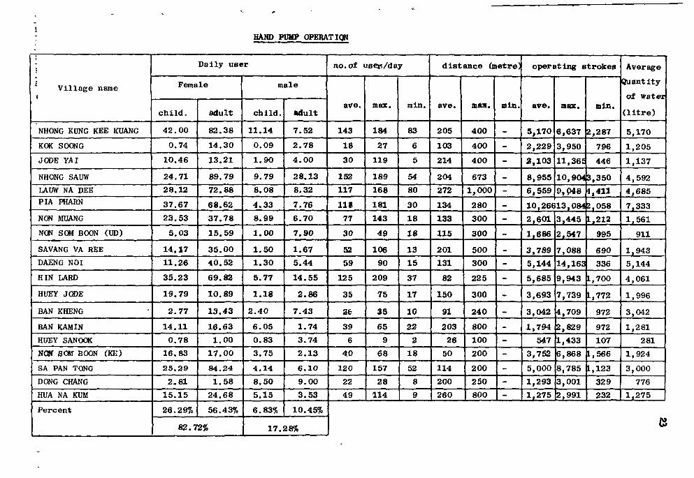
4.2 Hand Pump Operation
Operation data comprised d e t a i l s of hand pump operators (or water
fetchers) such as sex, age, and other data re lat ing t o the operation
including of operating strokes by each operator, number of strokes the
hand pump was operated each day, and volume of water pumped up each
day. The summary of these data i s shown in Table 3.
The findings obtained from analysis of the operation data are
interpreted as fol lows:
(1) Most of hand pump operators, or about 85 percent, were women.
This finding i s considered common for rural areas in Thailand where
women have t o take care of most of household work including water
fetching.
(2) About one third of hand pump operators were children with
ages below 15 years, and t h i s i s a lso normal in rural areas where most
of children in working ages are taught t o help t h e i r parents in a l l
a c t i v i t i e s in which they can part ic ipate . Hence, the hand pumps should
be designed and ins ta l l ed in such a manner that they can be eas i ly
operated by working-age children. This means that proper considerations
should be made of the following design c r i t e r i a : the s i z e of the hand pump
HAND PUMP OPERATION
V i l l a g e name i
NHONG KUNG KEE KUANG
KOK SOONG
JODE YAI
NHONG SAUW
LAUW NA DEE
PIA PHARN
NON MUANG
NON SOM BOON (UD)
SAVANG VA REE
DAENG NOI
HIN LARD
HUEY JODE
BAN KHENG
BAN KAMIN
HUEY SANOOK
NOW SOW BOON (KK)
SA PAN TONG
DONG CHANG
HUA NA KUM
P e r c e n t
D a i l y u s e r
Female
c h i l d .
4 2 . 0 0
0 .74
1 0 . 4 6
2 4 . 7 1
2 8 . 1 2
3 7 . 6 7
2 3 . 5 3
5 . 0 3
1 4 . 1 7
1 1 . 2 6
3 5 . 2 3
1 9 . 7 9
2 . 7 7
1 4 . 1 1
0 . 7 8
1 6 . 8 3
2 5 . 2 9
2 . 8 1
1 5 . 1 5
26 .29%
8 2 . 7
a d u l t
8 2 . 3 8
1 4 . 3 0
1 3 . 2 1
8 9 . 7 9
7 2 . 8 8
6 8 . 6 2
3 7 . 78
1 5 . 5 9
3 5 . 0 0
4 0 . 5 2
6 9 . 8 2
1 0 . 8 9
1 3 . 4 3
1 6 . 6 3
1 .00
1 7 . 0 0
8 4 . 2 4
1 .58
2 4 . 6 8
56 .43%
2%
ma le
c h i l d .
1 1 . 1 4
0 . 0 9
1 .90
9 . 7 9
8 . 0 8
4 . 3 3
8 .99
1 .00
1 .50
1 .30
5 .77
1 .18
2 . 4 0
6 . 0 5
0 . 8 3
3 . 7 5
4 . 1 4
8 . 5 0
5 . 1 5
6.83%
1 7 .
a d u l t
7 . 5 2
2 . 7 8
4 . 0 0
2 8 . 1 3
8 .32
7 . 7 6
6 . 7 0
7 . 9 0
1.67
5 .44
1 4 . 5 5
2 . 8 6
7 . 4 3
1.74
3 .74
2 . 1 3
6 . 1 0
9 . 0 0
3 . 5 3
10.45%
28%
n o . o f u s e r / d a y
a v e .
143
18
30
152
117
I I S
77
30
52
59
125
35
2 t
39
6
40
120
22
49
max.
184
27
119
189
168
181
143
49
106
90
209
75
35
65
9
68
157
28
114
min .
83
6
5
54
80
30
18
18
13
15
37
17
10
22
2
18
52
8
9
d i s t
a v e .
205
103
214
204
272
134
133
115
201
131
82
150
91
203
26
50
114
200
260
ance (me t r e ]
max.
400
400
400
673
1 ,000
280
300
300
500
300
225
300
240
800
100
200
200
250
800
min.
-
-
-
-
-
-
-
-
-
-
-
-
-
-
-
-
-
--
o p e r a t i n g s t r o k e s
ave .
5 ,170
2 , 2 2 9
2 , 1 0 3
8 ,955
6 , 5 5 9
max.
6 ,637
3 ,950
11,36£
min.
2 ,287
796
446
10 ,904 3 ,350
9 , 0 4 8 1,411
10 ,26613 ,084 2 ,058
2 , 6 0 1
1,686
3 , 7 8 9
5 ,144
5 ,685
3 , 6 9 3
3 ,042
1,794
547
3 ,752
5 ,000
1,293
1 ,275
3 , 4 4 5
2 , 5 4 7
7 , 0 8 8
1 4 , 1 6 3
9 , 9 4 3
7 , 7 3 9
4 , 7 0 9
2 ,829
1 ,433
6 , 8 6 8
8 , 7 8 5
3 , 0 0 1
2 , 9 9 1
1,212
995
690
336
1,700
L,772
972
972
107
L.566
L.123
329
232
Average
Quant i t y
of w a t e r
( l i t r e )
5 ,170
1 ,205
1 ,137
4 , 5 9 2
4 , 6 8 5
7 , 3 3 3
1 ,561
911
1 ,943
5 ,144
4 , 0 6 1
1,996
3 ,042
1,281
281
1,924
3 , 0 0 0
776
1 ,275
Ci

handle assemblies, the length of the handle, and the force to be exerted
by the operator's hand in order t o operate the hand pump.
(3) The maximum number of operating strokes of each hand pump
was found t o be 10,266 strokes/day, and the average was about 4,000
strokes/day. These data are useful bases in redesigning and improvement
of the hand pumps, and emphasis should be made t o manufacture a pump
with low f r i c t i o n , wear and tear under the maximum operating load of
not l e s s than 10,000 strokes per day. For example, i f a hand pump i s
to be designed or improved t o have an operation l i f e of at l eas t 6
months, a l l parts of the hand pump must be designed or improved t o
withstand the maximum operating conditions of more than 1,800,000
strokes without any damages.
(4) The maximum walking distance from the operator's house t o
the deep wel l was 1,000 metres. Therefore, in se lec t ing the s i t e for
d r i l l i n g a deep wel l or for digging a shallow wel l in order t o i n s t a l l
a band pump, the walking distance should a l so be considered as wel l .
It i s recommended that the walking distance should not exceed 500
metres and that the deep wel l should be d r i l l e d at or near the center
of the v i l l a g e where the population i s dense. However, other factors
as previously stated in Section 5 should a l s o be considered for wel l
d r i l l i n g s i t e s e l ec t ion .
(5) As a resul t of r e l a t i v e l y large numbers of the hand pump
operators per day found in t h i s study, i t i s indicated that one hand-
pump-equipped deep wel l may not be su f f i c i ent for each v i l l a g e .
Hand Pump Capability, Mechanical Character is t ics , Operating Force and
Price of Hand Pump
This data are summarized for each type of the tes ted hand pumps
in Table 4 through Table 7.
By comparison of the capabi l i ty data among di f ferent types of
hand pumps the re su l t s can be discussed as fo l lows:
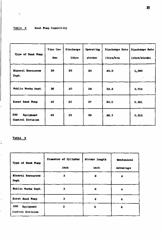
25
Table 4 Hand Pump Capability
Type of Hand Pump
Mineral Resources
Dept.
Publ ic Works Dept.
Korat Band Punp
ARD Equipment
Control D i v i s i o n
Time Use
Sec
30
36
40
45
Discbarge
l i t r e
20
20
20
20
Operating
s troke
20
28
37
39
Discbarge Rate
l i t r e / m i n
4 0 . 0
3 3 . 3
3 0 . 0
2 6 . 7
Discharge Rate
l i t r e / s t r o k e
1.000
0.714
0.541
0.513
Table 5
Type of Hand Punp
Mineral Resources
Dept.
Publ ic Works Dept.
Korat Hand Pump
ARD Equipment
Control D i v i s i o n
Diameter of Cylinder
inch
3
3
3
3
Stroke length
inch
6
6
4
2
Mechanical
Advantage
4
4
6
8

Table 6
26
Typ« of Haad Pump
Mineral Resources Dept.
Public Works Sept .
Korat Hand Pump
ARD Equipment Control
D i v i s i o n
Operating Load per Head
in Foot of Water
0.4815
0.4710
0.3226
0.2212
Operating Load per Head in
Foot of Water When Mechanical
Advantage = 4
0.4815
0.4710
0.4838
0.4424
Table 7
Type of Hand Pump
Mineral Resources Dept.
Public Works Dept.
Eorat Hand Pump
ARD Equipment Control
D i v i s i o n
P r i e s
1,509
1,643
1,500
2 , 2 0 0
Number of Parts
85
96
89
72
27
(1) The Department of Mineral Resources (DMR) hand pump gives
the highest water discharge not only in litres/minute but also in
litres/stroke. This is because it has the longest pumping stroke as
compared with those of the remaining three types. Although the DMR
hand pump requires a longer time for each operating stroke, the pumping
time does not vary directly with the time for each operating stroke.
Other factors influencing the pumping time include operating force,
mechanical advantage, pumps handle heights for operating comfort, and
the arc swept by the end of the handle.
(2) The ARD Equipment Control Division hand pump requires the
lowest operating force per one foot ol the lifted water column at a
given (adjusted) mechanical advantage. This means that this type of
hand pump has the lowest friction losses at various contacting parts
assuming that back leakage between the plunger and the cylinder wall
during each pumping time is the same for all types of the tested pumps.
(3) In addition to the analysis of the basic data as stated in
Items (1) and (2) above, the advantages and disadvantages of cylinder
crank and the performance of these hand pumps can be compared as follows:
(a) Mineral Resources Department Hand Pump
Advantages:
(i) The air chamber helps maintain continuous flow pf water
instead of intermittent flow.
(ii) The hand pump handle is made of single piece of cast iron,
with appropriate shape and size, which causes no pain to the operating
h»nd,«and the handle is long lasting.
Disadvantages
(i) The contact between the axle and bushing is a direct contact
between the two metal parts, which causes rapid wear if lubrication is
not carried out sufficiently.
(ii) There are several moving parts. If the axle becomes impaired
the handle would move to and for horizontally, which would cause damages
to other parts more easily.

28
(iii) The vertical movement of the pumping rod needs a sliding
crosshead which is relatively loose. This would affect the vertical
movement of the pumping rod, causing vibration while functioning.
Thus, the pumping rod may become bent or worn out more easily.
(iv) The plunger could slam the upper and lower parts of the
cylinder if it is not properly installed, and this would easily create
damages to the cylinder and pumping rod.
(b) Public Works Department Hand Pump; Since the major
characteristics of this type of hand pump are the same as those of
the Mineral Resources Department pump, it has the same advantage and
disadvantages as described above.
(c) Health Department Hand Pump. (Korat Hand Pump)
Advantages:
(i) Vertical movement of pumping rod depends on rack and pinion.
The pinion sector rotates on the axle pin causing the rake to move up
and down against two fixed rollers which lead to better vertical move
ment. This wvld result in less vibration at the pumping rod making it
difficult to ~e bent or to be broken.
(li) There are only a few moving parts subject to wear and tear,
(iii) There are shock absorbing springs to prevent the plunger from
slapping upper and lower parts of the cylinder.
Disadvantages:
(i) There is no air chamber to keep water running continuously
during the operation.
(ii) The handle and pinion sector °»e separate parts. Thus, pump
operation easily causes damage to the handle at the point of contact
between handle and pinion sector.
(fl) ARD Equipment Control Division Hand Pump
Advantages:
(i) The ball bearing at rotating parts significantly minimize
maintenance problems.
(ii) The use of crank shaft for fixing the highest and the lowest
movement levels of the plunger can prevent plunger from slamming to
the cylinder's upper and lower parts.
Disadvantages:
The disadvantages of this type of hand pump are exactly the same
as those of the Karat Hand Pump.
The comparisons of advantages and disadvantages among different
types of hand pumps as shown above are restricted to the upper part
from the pump handle to the pump rod linkage mechanism. The lower
part, which includes the drop pipe, pump rod, plunger and cylinder,
is generally of the same character for all four types of hand pumps.
As for this part, there is one obvious difference, i.e., the cylinders
of the hand pumps of Mineral Resources and Public Works Departments
are made of brass while those of the Health Department Type 608 and
ARD Equipment Control Division are made of PVC. The brass cylinder
is usually more durable than the PVC cylinder. Additionally, the PVC
cylinder is move liable to damages when it is dismantled for maintenance
because it can be broken while being tightended with excessive force.
Deterioration and Damages of Hand Pumps
The data on deterioration and damages of each type of hand pump
were collected by each responsible maintenance unit during the testing
period of this project. However, collection of these data has currently
been continued even though the project has ended since January 1979.
Based on the data gathered during the testing period, the following
findings can be summarized:
30
(a) Mineral Resources Department Hand Pump
( i ) Average number of operating strokes: 3,500 strokes
per day.
( i i ) Worn out parts:
1. Severe deteriorat ion was found at the three
rotating parts. The most severely worn out part was observed at the
f i r s t rotating spot (see I l lus trat ion No. 1 ) .
2 . The c o t t e r pin was missing.
3 . All nuts became loosened.
( i i i ) Damage: The top rod was broken once.
(b) Public Works Department Hand Pump
( i ) Average number of operating strokes: 3,500 strokes
( i i ) Worn out parts:
1. Severe wear and tear were found at a l l of the
three rotating spots espec ia l ly at the f i r s t one (see I l lus trat ion No. 1 ) .
2 . The cot ter pin was missing.
3 . Various nuts became1 loosened.
( i i i ) Damage: The pump rod of one hand pump was broken
at the coupling.
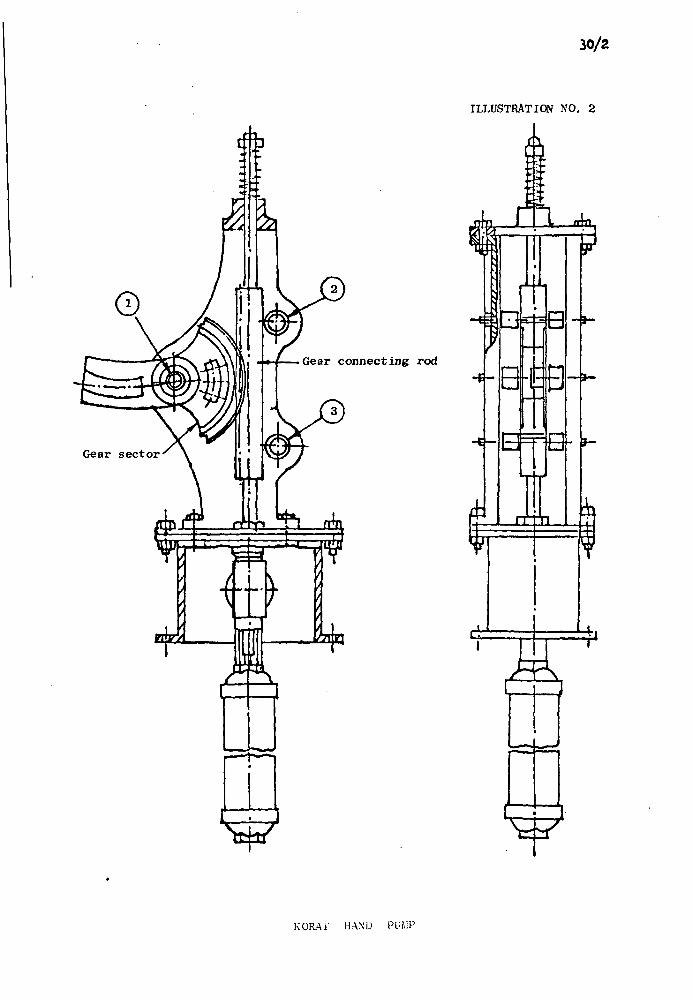
(c) Department of Health Hand pump (Kbrat hand pump)
( i ) Average number of operating strokes: 2,400 strokes
per day.
( i i ) Worn out parts:
1. All of the rotating parts were found to be
worn out especia l ly the f i r s t rotating spot (see I l lus tra t ion No, 2 ) .
2. The pinion sector and the rack were s l ight ly
worn out.
3 . The nut and the handle became loosened,
( i i i ) Damage: None was found.

30/1
Flat bar
ILLUSTRATION NO. 1
Circle bar
DDR HAND PUMP
30/2
ILLUSTRATION NO. 2
Gear connecting rod y
&
A _om
1
B
B »
S
E0
ur a
P
G LA.
M J-t,
W
KORAT HAND PUMP

31
(d) ARD Equipment Control Division Hand Pump
(i) Average number of operating strokes: 4,200 strokes
per day.
(ii) Worn out part: The crosshead was slightly worn out.
(iii) Damage: None was found.
5. Improvement of hand pump design
5.1 Hand Pump Improvement
Analysis of data on worn out and damaged parts of each type of
hand pumps was used as a guideline for its improvement. Based on*
the results of this study, each type of hand pumps was Improved
and then re-installed for further testing. These improvement were
made separately for the two different parts of each pump, namely
(i) the upper part from the pump body and hand pump handle down to the
pump rod linkage mechanism, and (ii) the lower part including the pump
rod, the coupling and, the cylinder assembly. Experiences of the hand
pump testing programme have indicated that iapMrements of each hand
pump type should be as follows:
(1) Improvement of Upper of Hand Pump
(a) Mineral Resources and Public Works Department Hand Pumps
As previously stated, the characteristics of these two types of hand pumps
are the same. Improvements made as follows:
(i) Use better grade nuts and bolts and put to every nut
and bolt with lock washer in order to prevent from loosing
(ii) Strengthen the .fulcrum Jink, by usiag a bigger one.
(iii) Add brass bushes into all bores that have moving
parts in them, such as all bores in the handle, fulcrum link in
order to lower the cost of repair (When a bore is deteriorated, it can
be replaced easily by putting the new bush instead of changing the
whole new part)
32
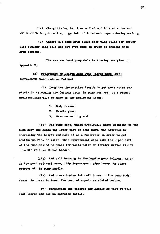
(iv) Change the top bar from a flat one to a circular one
which allow to put coil springs into it to absorb impact during working.
(v) Change all pins from plain ones with holes for cotter
pins locking Into bolt and nut type pins in order to prevent them
from loosing.
The revised hand pump details drawing are given in
Appendix D.
(b) Department of Health Hand Pump (Korat Hand Pump)
Improvement were made as follows:
(i) Lengthen the strokes length to get more water per
stroke by extending the fulcrum from the pump rod and, as a result
modifications will be made of the following items.
1. Body frames.
2. Handle gear.
3. Gear connecting rod.
(11) The pump base, which previously makes standing of the
pump body and holds the lower part of hand pump, was improved by
increasing the height and make it as a reservoir in order to get
continuous flow of water, this Improvement also make the upper part
of the pump sealed no space tor waste water or foreign matter fallen
into the well as it has before.
(ill) Add ball bearing to the handle gear fulcrum, which
is the most critical wear, this improvement also lower the force
exerted at the pump handle.
(iv) Add brass bushes into all bores in the pump body
frame, in order to lower the cost of repair as stated before.
(v) Strengthen and enlarge the handle so that.it will
last longer and can be operated easily.

33
The revised parts details drawing of the Korat pump
are given in Appendix D.
(c) ARD Equipment Control Division Hand Pump
Improvement were made as follows:
(i) Lengthen the stroke length to get more water
per stroke by extending the crank shaft in proportion to the
connecting rod, and by lengthening the U - joints.
(ii) Improve the pump base in the same manner as
described for the Health Department hand pump.
(iii) Strengthen the handle by making as Z - Sided assembly
locked together by nuts and bolts.
The revised parts details drawing of this pump
are given in Appendix D.
(2) Improvement of Lower Part of Hand Pump
As the lower part of all hand pump covered in this project are
almost the same, the differences are the kind of material and some
dimension of parts. So the improvements should be generally made
the same as follows:
(i) Increase the size of the drop pipe from lj inch to
lj inch in order to have enough room for a centering guide. (Except the
Public Works Department hand pump which already has 1$ inch drop pipe).
(ii) Use brass cylinder instead of PVC cylinder (Except
the Mineral Resources Department and the public Works Department hand pumps
which already have brass cylinder).
(iii) Increase the size of the pump rod from 7 inch to
\ inch.
(iv) Lengthen the pump rod coupling.

34
(v ) Add a brass c e n t e r i n g g u i d e f o r t h e pump rod by put
i t in t h e drop p ipe coup l ing between t h e ends of two p i e c e s of p i p e s .
The d e t a i l s drawing of t h e r e v i s e d lower p a r t s of
t h e pumps are g i v e n in Appendix D.
<
5 .2 Data C o l l e c t i o n and A n a l y s i s a f t e r I n s t a l l a t i o n of Improved Hand Pumps
As s t a t e s p r e v i o u s l y , d i f f e r e n t p a r t s of each t y p e of hand pumps
were redes igned based on a n a l y s i s of d a t a on hand pump damages
obta ined from t h e f i e l d t e s t s . These p a r t s were manufactured, and
t h e new improved hand pumps r e - i n s t a l l e d at corresponding t e s t i n g
l o c a t i o n s and were then operated in t h e same manner as they were
p r e v i o u s l y . The i n s t a l l a t i o n and t e s t i n g p l a n are as f o l l o w s :
Type of pump No. I n s t a l l e d T e s t i n g Durat ion Ave. Operating Day Stroke/Day
Mineral Resources Dept . 1 60 2 ,484
Publ i c Works Dept.
Dept. of Heal th 2 6d 5 , 7 9 8 , 767
ARD Equipment 1 6» 3 ,752
Control D i v i s i o n
Data c o l l e c t i o n t o be c a r r i e d out during t h i s t e s t i n g per iod was
properly planned s o t h a t t h e d a t a can be used as t h e b a s i s in making
the f o l l o w i n g comparisons between t h e improved pumps and t h e corresponding
old pumps:
(1 ) D e t a i l s of hand pump damages
(2 ) Operating per iod when f i r s t o b s e r v a t i o n of was made of
d e t e r i o r a t i o n
(3) Tota l p r i c e of hand pump
(4) T o t a l number of p a r t s
(5 ) Operating ages of d i f f e r e n t p a r t s

35
(6) Preventive maintenance
(7) Total cost (initial plus operating costs)
(8) Operational efficiency
The d e t a i l s of these comparison are given in Appendix B.
6. Recommendat ions
As a resu l t of the f i e l d t e s t i n g , i t i s recommended that the
DMR's hand pump and the Korat hand pump be used for the National Rural
Water Supply Programme. Other types of hand pump should be eliminated
from the programme.
Additionally re su l t s of t h i s study have indicated that the
improvement of hand pump operation has t o take into account the
hand pump i t s e l f and the other factors as we l l , i . e . , the improvement
of the wel l d r i l l i n g plans and operations, as wel l as the maintenance
and repair a c t i v i t i e s . The following are recommended.
6.1 Improvement of Hand Pump
With respect t o the Improvement of the hand pump, the related
a c t i v i t i e s should include improvement of hand pump design, quality
control of hand pump manufacture, and improvement of in s ta l l a t i on
work.
(1) Improvement of Hand Pump Design
The following factors should be taken into consideration:
(a) The improved hand pump should sui t actual operating
conditions in rural areas, i . e . , ( i ) i t should requires minimum
maintenance, ( i l ) an operating time before i t s spare - parts have
t o be changed should standardized so that replacements can be
done regulary even though, for some instance, s igni f icant wear
and tear have not occurred, and ( i i i ) spare - parts should be
replaced eas i l y and with low cos t s .

36
(b) The pump should be easy to operate with respect to the
required operating force and the heights of the pump and its
handle.
(c) The pump should not be too expensive.
(2) Quality Control of Hand Pump Manufacture
With regards to quality control, the items which should be
considered carefully include manufacturing materials, size of
each part, and the center line of the pump. All of the parts,
including the plunger and cylinder assembly, the pump rod, pipes
threads, and joints, should be inspected thoroughly before the
pump is assembled.
(3) Control of Hand Pump Installation
Hand pump installation is one of the most important steps
which determine the life of the pump. Poor installation can
lead to a greater force to operate the pump and subsequent damages
of the pump. Hence, hand pump installation should be carried
out under supervision of experienced field personnel.
6.2 Hand Pump Programme
A hand pump programme normally includes the following activities:
installation, maintenance, repair, and manufacture, for which recommenda
tions can be described as follows:
(1) Hand Pump Installation
Due to the fact that installation of a hand pump by a well
drilling operation unit can result in operational problems and
damages, it is recommended the following steps be taken in
installation of a pump:
(a) Check various parts of the hand pump to be installed,
especially the plunger and cylinder assembly, the length, size
and thread of the drop pipe; and the length of the pump rod (which
should be compatible with the length of the drop pipe) Additionally,
attemps shoflld be made to avoid field outting and joining of the

37
drop pipe. In Other words, it is more appropriate to cut the pipe
and standardize the thread for upper part of the pump rod at the
operation unit or center, not in the field.
(b) Transportation of various parts of hand pumps from one
unit to the operation site for installing should be carried out
with care in order to avoid damages to the transported parts.
(c) Pipe connection and assembly of parts should be carried
out correctly, with tools and accessories being used correctly for
various tasks, especially inconnecting the drop pipe with the
pump rod which has to be screwed in tightly. In order to prevent
undue wear and tear of the thread, which is one of the major
problems causing the drop pipe and the pump rod to be broken, an
appropriate pipe connection compound should be applied sufficiently
at the thread.
(d) To facilitate hand pump operation., the pump handle should
be located at an appropriate level neither too high nor too low
from the ground level. By taking children operators into account,
the maximum height of the handle should not exceed 1 meter.
(e) There should be a fairly wide concrete slab around the
deep well provided with a proper drainage.
(f) After a hand pump has been installed, there must be
neither holes nor leak to allow the water to flow back into the
deep well nor an opening to allow undesirable materials such as
pebbles or pieces of wood to fall or to be put into the well.
(g) The number of pieces of the drop pipe should be kept
to a minimum and the length of the drop pipe should be more or
less the same as the pumping level of the deep well. A drop pipe
which is too long can easily cause damages to the drop pipe and
pump rod due to excessive vibration.
(h) Records should be made for each deep well and hand pump
installed, and should include details of the following items:

38
(i) Type and model of the hand pump,
(ii) Size, type and length of the drop pipe,
(iii) Size and type of plunger and cylinder assembly,
(iv) Size, type and length of the pump rod,
(v) Size of the deep well,
(vi) Static water level,
(vii) Yield of the deep well,
(viii) Draw down level, and
(ix) Other related details.
(2) Improvement of Well Drilling ?lan
Based on the present study, which comprised selection of deep
wells for the testing programme, collection of daily water utiliza
tion data, and analysis of the data, the criteria for the deep well
drilling plan for Thailand are recommended as follows:
(a) To establish an extensive plan for well drilling operation,
a nation-wide master plan should be drawn up to suit local conditions
such as the source and quality of ground water, and the number of
population in each community. This plan should then be subdivided
into three categories:
(i) A plan for drilling deep wells for agricultural
water supply should be established for areas where the existing
ground water resources are of high quality and ample quantity,
and in areas where no sources of surface water are available.
Where surface water is available development of such a source for
irrigation water supply should be given a higher priority because
its operating cost is much lower than that of a gnound water supply
system.
(ii) A plan for drilling community water supply deep well
should be drawn up for fairly populous areas where the existing
ground water sources are of high quality and sufficient quantity.
(iii) A plan for drilling deep well equipped with hand
pumps should establish for areas where the existing ground water
sources are of good quality and, where shallow wells can provide
39
sufficient supplies, they should be the first choice of development
because operating costs of this third plan are extremely high.
After the master plan has already been established, the
responsibility of well drilling operation of each responsible unit
should be distinctively divided according to the objectives of
the deep well. If there are many units having the responsibility
for the same objective of the deep well in a province especially
for drilling operation of hand-pump-installed deep wells for rural
domestic water supply, such a responsibility should be assigned
to the government unit that will be responsible for the whole area
of the province. This would facilitate the repair and maintenance
operation in the future because all hand pumps installed in a
given province would be of the same type.
In case the plan for drilling operation oan be divided
according to the objective, of wells operating costs in each area
would be lower than they are at present. For example, a hand-pump-
installed deep well for domestic water supply usually require smaller
casing,screen or slotted pipe than the well for the irrigation
purpose. In this case, the purpose of the well drilling and develop
ment will be limited to obtaining a water yield which does not
exceed the capacity of the hand pump.
(b) After the master plan has been established, the operation
schedule for drilling hand-pump-installed deep wells for domestic
water supply should be prepared based on the following criteria:
(i) Since the site to be selected for well drilling is
the site where the hand pump is to be installed, it is necessary
to take into account various factors that would affect maintenance
of the pump. Additionally, it would be a worthwhile investment
to install the hand pumps at the places where they will be utilized
by as many people in the village as possible. The following are
the criteria for selecting a drilling site;
1. The site should be located at the cownunity center,
2. The site should be located near or in the public area
under the responsibility of the respectable people, such as in the
temple boundary or in t he area c lose t o t he v i l l a g e headman's
house.
( i i ) The t o t a l number of deeft we l l s t o be d r i l l e d for
hand pump i n s t a l l a t i o n in each community should be l a rge enough
t o be able t o serve t he populat ion growth, in order t o minimize
t h e expenditure of fu tu re wel l d r i l l i n g . If more than two hand-
pump-instal led deep we l l s a re provided in each community, water
shor tage would not be a s e r ious problem when one hand pump i s
out of order . I t i s suggested t h a t t h e number of people t o be
served by a hand-pump-instal led deep wel l should not exceed 300.
(3) Hand Pumps Maintenance and Repair
In most p a r t s of r u r a l areas in Thailand, maintenance and
r e p a i r of hand pumps can be said t o be a j o i n t e f fo r t between
the v i l l a g e s and the r e spons ib l e agencies . For bas ic maintenance
such as regula r l u b r i c a t i o n and minor r e p a i r s , t h e t a sk can be
assigned t o r espons ib le persons such as v i l l a g e chief (Kamnan),
v i l l a g e headman (Pu y a i ban) , t eacher of Bhuddhist monk. However,
in case of major damages which are beyond t h e capaci ty of these
people, including pump rod damage and pump f a i l u r e , t h e respons ib le
agency must be informed so t h a t appropr ia te r e p a i r s can be made
by experienced personnel of t he agency.
In carrying out the above-mentioned j o i n t e f f o r t , only a few
p r a c t i c a l gu ide l ines for t he bas i c maintenance and minor r e p a i r s
a re provided t o t h e r e spons ib l e v i l l a g e r s . Although maintenance
and r e p a i r t r a i n i n g courses for t he se people are sometimes arranged
by some of t he r e spons ib l e agencies or u n i t s , t he se are not a
r egu la r undertaking. As for t he maintenance programmes of the
c e n t r a l r e spons ib le agencies , t he operat ion can be divided in to
two systems. For t he f i r s t system, which is employed by the Mineral
Resources Department, mobile maintenance u n i t s a re se t up t o monitor the
performance of t h e i r own hand pumps, and t o maintain and r e p a i r
them when the needs a r i s e . The other system is p rac t i s ed by the o f f ice
of Accelerated Rural Development (ARD) and t h e Department of Health.
In t h i s l a t t e r case , each c e n t r a l r espons ib le agency ass igns the

maintenance and repair responsibility to its own local or the provincial
units. By using this system, the maintenance and repair work of the ARD
hand pumps is under the responsibility of the ARD provincial
Chief who works at the Provincial Organization, which is a local
administrative unit. Likewise, the Provincial Health Officer is
responsible for the maintenance and repair work of the Public
Health Department hand pumps in each province.
The current maintenance and repair programmes utilizing the
joint effort as mentioned above facting some problems. These include:
(i) inadequate maintenance and repair capabilities of villagers,
(ii) insufficient maintenance and repair budget allocated to each
of the responsible agencies, and (iii) relatively poor quality
of each type of hand pump. These problems have already been stated
in the part relating to background of the problems, and can be divided
into two major categories, namely administrative problems and technical
problems. Results of field testing of this hand pump improvement
project have indicated that the problems largely result from poor
techniques which are to be solved according to recommendations given
previously. However, once the technical problems have been solved, the
associated administrative problems should also be solved, as follows:
(a) Management of Maintenance and Repair Work: This should
be undertaken based on the following guidelines:
(i) Level of responsibility: there snould be two levels
of maintenance and repair responsibility: provincial and villages
levels. This means that when a central responsible agency has
installed hand pumps at deep wells, each of the deep wells should
be officially handed over to the Changwat (Provincial) Organizat ion.
The Changwat Organization should then establish its own hand pump
maintenance and repair units to execute the maintenance and repair
activities in the entire province. However, the central agencies
will provide the technical backstopping to the Changwat Organiznt 1 or..

42
With this arrangement, administrative problems will
be reduced by a great extent because the Changwat Organization
will be the sole agency responsible SOT maintenance and repair
of all hand pumps in the province. As a result, the hand pump
maintenance and repair programme will become more effective and
economical. Travelling expenses, the main component of the
overall expenditure, will be reduced substantially from those
incurred under the current programme using mobile units which
are responsible to the central responsible agencies.
(ii) Maintenance and repair budget: Sufficient main
tenance and repair budget must be obtained each year. Records
must be made of the existing number of hand pumps as well as the
repair and maintenance costs to be used for determining the
average repair and maintenance cost for each pump, and to prepare
a correct budget statement for the following year. If possible,
the budget should be allocated from the revenue of the Changwat
Organization. However, if the budget is too large for the Changwat
Organization to handle, the central responsible agency will have
to be in charge of this matter by subsidizing the Changwat Orga
nization with the amount of money estimated on the basis of the
records of the number of hand pumps installed in that province
and the average repair and maintenance cost per pump. Additionally,
the budget should be large enough to be also able to cope with
the projected or planned number of hand pumps to be installed in
that fiscal year.
(iii) Designation of responsibility: Specific responsi-" • • • • I - ' M l • • I I — I — — • • • M l — »
b i l i t i e s should be designated to both the vi l lagers and the local
responsible uni ts . At the vil lage level, a capable vi l lager should
be selected to be responsible for the maintenance task, and his
duties should include a l l simple maintenance a c t i v i t i e s . As for
the work which is beyond t h i s v i l l age r ' s capacity, t h i s has to be
handled by the local responsible unit in order to avoid undue
damages to the hand pump and to prolong i t s l i f e .
a
(iv) Operation schedule: The operation schedule for
the work of the local responsible unit must be set up with due
considerations, so as to obtain an effective and economical
maintenance programme. This should include the time schedule
for off icials to go out to maintain each hand pump, the kind of
each operation, and to t a l expenditure for each operation. Such
a local-level operation schedule should be prepared in advance
to be used as the annual operation shcedule.
(v) Personnel and appurtenances: Sufficial personnel,
equipment and vehicles for local responsible unit should be
estimated based on the operation schedule mentioned in Item (iv)
above.
(vi) Sufficient stock of accessories and spare-parts
of hand pumps should be provided to each local responsible unit,
and th i s should also be estimated in advance using the above -
mentioned operation schedule.
(vi i ) Records of hand pump maintenance and repair should
be made on a regular basis and should be checked periodically for
thei r correctness, and these records should be used for improvement
of the maintenance and repair programme in the following years.
7. Conclusion
7.1 This handpump study dealth entirely with the field testing, the data
collected were those obtained under the actual field conditions. These
are considered excellent bases for the improvement of handpump design,
handpump installation, well drilling plans and the plans for handpump
maintenance and repair. However it is not possible to evaluate the
effect of the water level on the force required to operate the handpump
due to the fluctuation of water level in each well which was not
controllable.

44
7.2 The findings and recommendations on the types of handpumps to be used
for the National Water Supply Programme has been presented to the
meeting among various agencies involved with the National Rural Water
Supply Programme. The meeting agree that the DMR and the Korat
handpumps be used for the National Rural Water Supply Programme as
recommended until the better type of handpump is found.
45
APPENDIX A
CHARACTERISTICS OF HAND PUMPS CURRENTLY IN USE IN THAILAND

4*
Several types of the existing band pumps installed in Thailand are
used by different government agencies which are responsible for deep well
and shallow well provision in rural areas. Each agency has been trying to
improve its own hand pump model, which can be either the one donated by
foreign countries or that of its own invention.
To review the characteristics of the hand pumps currently in use in
Thailand, different types of hand pumps are described as follows:
1. Mineral Resources Department Hand Pumps
The prototypes of the hand pumps used by this department are the
Demster, Red Jacket or other hand pumps donated by, or procured from,
the U.S. This type of hand pump has a 3-pin lever with a crosshead,
and the cylinder which is generally has a plunger with 2 plunger cup
seals and a valve poppet at the plunger. The lower valve is of the
spring activated poppet type having a 3" cylinder,-T" pumping rod,
and lj" drop pipe (See Figure A- 1).
2. Public Works Department Hand Pumps
The prototype of the pumps used by this department is the same
as that of the Mineral Resources Department. It also has a 3-pin
lever with a crosshead. The sizes of most parts are nearly the same
as the Mineral Resources Department hand pump, but its ly" drop pipe
is slightly larger. ( See figure A-2 )
Health Department Hand Pumps (Korat hand pump )
The cylinder and the plunger of this type of hand pump are the
separate parts. The rack and pinion were invented by Mr. Manop
Suphaphan of the Health Department in late 1950's, and the hand pump
is called the Korat hand pump, named after the second name of
Nakon riatchasima Province? where the Design is Originated
(formerly Health Department Type 608).
The cylinder of this hand pump is similar to that of the Mineral Resources
and Public Works Department hand pump, and has the following characteristics:
3" cylinder and 1—" drop pipe (See Figure A-3)
47
4. ARD Type
The prototype of this type of hand pump is the Korat hand pump,
with a 3" cylinder made of PVC and a 1-" drop pipe (See Figure A-3).
5. Local Administration Department Hand Pumps
This type of hand pump is used for shallow wells. Its prototype
is the Korat hand pump, with the cylinder and the drop pipe having the
same sizes as those of the Korat hand pump (See Figure A-3)
6. ARD Equipment Control Division Hand Pumps
This type of hand pump is especially designed for testing purposes
by the Equipment Control Division, Office of the Accelerated Rural
Development. The pump is a rotary crank type, with the cylinder and
other parts having the same sizes as those of Type 608. ( See Figure A-4 )
The above-mentioned hand pumps as well as their spare-parts, are
usually not available on the market. The hand pumps which can be
purchased on the market are those of the type having the cylinder in
tegral with the pump body, and are used for shallow wells or deep wells
with a pumping level of less than 25 feet. The pumps of this type are
generally installed at small private tube wells having a diameter up
to 2 .

48
Figure A - 1
Mineral Resources Department Hand Pump

49
Figure A-2
Public Works Department Hand Pump
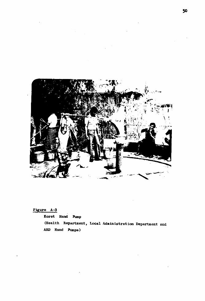
50
Figure A-3
Korat Hand Pump
(Health Repartment, Local Administration Department and
ARD Hand Pumps)

51
Figure A-4
ARD Equipment Control Division Hand Pump
52
APPENDIX B
COMPARISON BETWEEN OLD AND IMPROVED HAND PUMPS

53
1. Comparison of Details of Hand pump Damages.
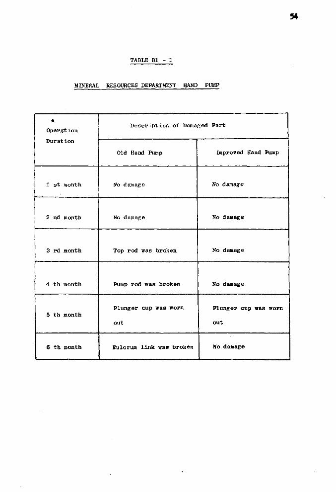
TABLE Bl - 1
MINERAL RESOURCES DEPARTMENT HAND PUMP
•
Operat ion
Durat ion
1 st month
2 nd month
3 rd month
4 th month
5 th month
6 th month
Description of Damaged Part
Old Hand Pump
No damage
No damage
Top rod was broken
Pump rod was broken
Plunger cup was worn
out
Eulcrum link wa« broken
Improved Hand Pump
No damage
No damage
No damage
No damage
Plunger cup was worn
out
No damage
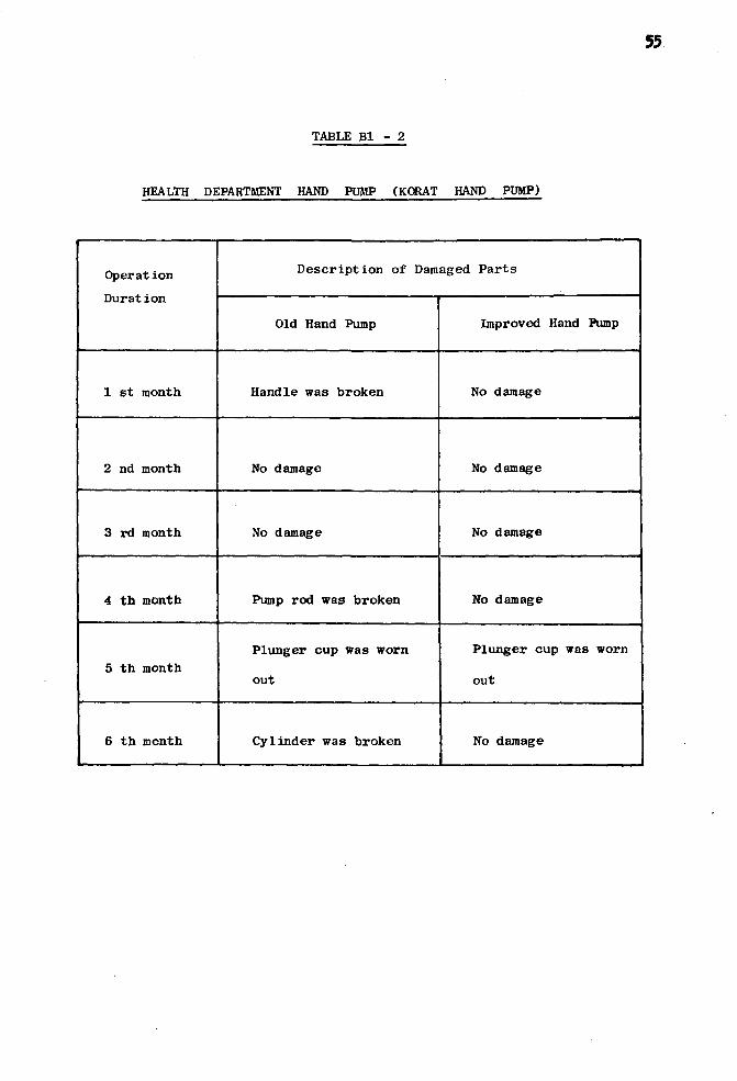
TABLE Bl - 2
HEALTH DEPARTMENT HAND PUMP (KORAT HAND PUMP)
Operation
Durat ion
1 st month
2 nd month
3 rd month
4 th month
5 th month
6 th month
Description of Damaged Parts
Old Hand Pump
Handle was broken
No damage
No damage
Pump rod was broken
Plunger cup was worn
out
Cylinder was broken
Improved Hand Pump
No damage
No damage
No damage
No damage
Plunger cup was worn
out
No damage
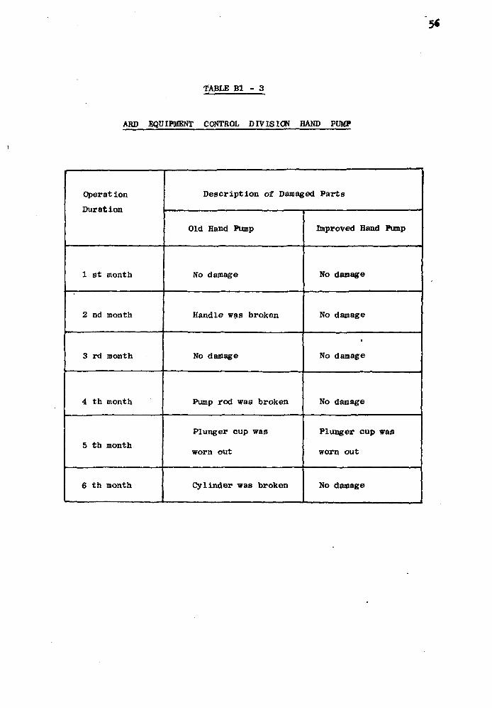
TABLE Bl - 3
ARD EQUIPMENT CONTROL DIVISION HAND PUMP
Operation
Duration
1 st month
2 nd month
3 rd month
4 th month
5 th month
6 th month
_
Description of Damaged Parts
Old Hand Pump
No damage
Handle was broken
No damage
Pump rod was broken
Plunger cup was
worn out
Cylinder was broken
Improved Hand Pump
No damage
No damage
No damage
No damage
Plunger cup wad
worn out
No damage
57
2. Comparison of Operating Periods when F i r s t Observations
of De t e r i o r a t i on of Dif ferent Pa r t s a r e Made

58
TABLE B2 - 1
MINERAL RESOURCES DEPARTMENT HAND PUMP
Part
Flat bar
Guide Flat bar bushing
Circle bar
Circle bar bushing
Guide circle bar bushing
Fulcrum link
Fulcrum link bush
Bottom fulcrum pin
Top fulcrum pin
Eye pump pin
Pump handle
Pump handle bush
Plunger cup
Connecting rod guide
Period When Observation of First
Deterioration Were Occured, month
Old Hand Pump
2
i-i
-
-
-
2
-
2
2
2
2
-
2
-
Improved Hand Pump
-
-
2
1
1
No.deterioration
1
2
2
2
No. d et er ior at ion
1
2
1
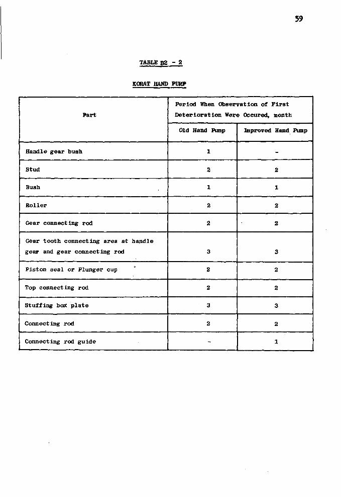
59
TABLE B2 - 2
KORAT HAND PUMP
Part
Handle gear bush
Stud
Bush
Roller
Gear connecting rod
Gear tooth connecting area at handle
gear and gear connecting rod
Piston seal or Plunger cup
Top connecting rod
Stuffing box plate
Connecting rod
Connecting rod guide
Period When Observation of First
Deterioration Were Occured, month
Old Hand Pump
1
2
1
2
2
3
2
2
3
2
-
Improved Hand Pump
-
2
1
2
2
3
2
2
3
2
1
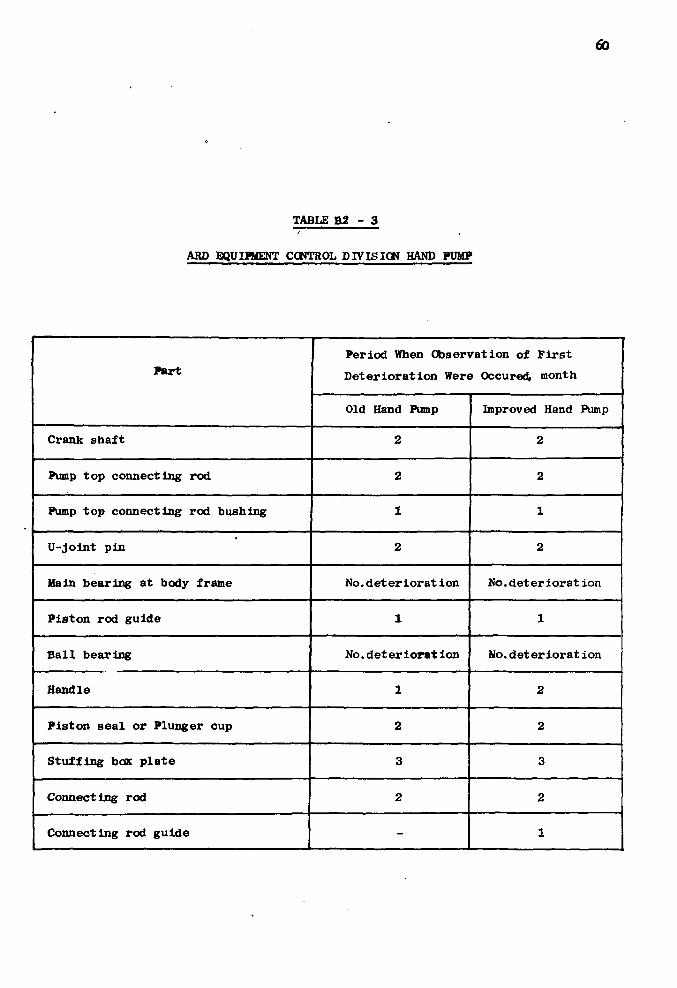
60
TABLE B2 - 3
ARD EQUIPMENT CONTROL DIVISION HAND PUMP
Part
Crank shaft
Pump top connecting rod
Pump top connecting rod bushing
U-Joint pin
Main bearing at body frame
Piston rod guide
Ball bearing
Handle
Piston seal or Plunger cup
Stuffing box plate
Connecting rod
Connecting rod guide
Period When Observation of First
Deterioration Were Occured, month
Old Hand Pump
2
2
1
2
No.deteriorat ion
1
No.deter iorat ion
1
2
3
2
-
Improved Hand Pump
2
2
1
2
No.deteriorat ion
1
No.deterioration
2
2
3
2
1

61
3. Comparison of Total Number of Parts of Hand Pump

62
TABLE B3
COMPARISON OP TOTAL NUMBER OF PARTS OF HAND PUMP
Type of Hand Pump
Mineral Resources and Public Works
Department Hand Pump
Korat Hand Pump
ARD Equipment Control Division Hand Pump
•
No. of Parts per Set (at 60 ft. setting)
Old Hand Pump
85
89
72
Improved Hand Pump
94
92
75

63
4. Comparison of Operating Ages of Hand Pumps

TABLE B4 - 1
MINERAL RESOURCES DEPARTMENT HAND PUMP
Part
Pump top gasket
Flat bar
Circle bar
Circle bar bushing
Guide circle bar bushing
Fulcrum link
Fulcrum link bush
Bottom fulcrum pin
Top fulcrum pin
Eye pump pin
Pump handle
Pump handle bush
Cylinder gasket
Circle bar spring
Cylinder wire spring
Operating Age, month
Old Hand Pump
4
12
-
-
-
6
-
8
8
8
12
-
4
-
8
Improved Hand Pump
6
-
>12
6
6
>12
6
12
12
12
>12
6
6
6
12

65
Part
B o l t s & n u t s
Connecting rode g u i d e
Pump body
Base p l a t e
P l a i n spout
Spout gaske t
Pump t o p
P i s t o n rod
Cyl inder s h e l l
Top cap
Bottom cap & i n l e t v a l v e s e a t
I n l e t v a l v e hous ing
I n l e t v a l v e
I n l e t v a l v e l i n i n g
Plunger f o l l o w e r
Operating Age, month
Old Hand Pump
4
8
> 1 2
12
> 1 2
> 12
> 12
depends on i n s t a l l i n g condi
t i o n
> 12
> 12
> 12
> 12
> 12
> 12
> 1 2
Improved Hand Pump
6
12
> 1 2
12
> 12
> 12
> 1 2
> 12
> 12
> 12
> 12
> 12
> 12
y 12
> 12

66
Part
Plunger cup spacer
Plunger valve
Plunger cup
Plunger cage
Plunger rod
Pipe
Coupling
Operating Age, month
Old Hand Pump
> 12
> 12
4
> 12
Improved Hand Pump
>12
> 12
6
> 12
depends on installing condition and water properties
depends on installing condition and water properties
8 12

TABLE B4 - 2
KORAT HAND PUMP .
i
Part
Body
Handle g e a r
Gear connect ing rod
Connecting rod
Top connect ing rod
S t u f f i n g box p l a t e
Pump base
Spring
Bush
Stud
Cover
Handle g e a r bush
P ipe
Pipe coupl ing
Hex. coup l ing
Operating Age, month
Old Hand Pump
> 12
12
6
6
6
> 1 2
3
3
6
> 12
3
Improved Hand Pump
> 1 2
> 12
12
12
12
> 12
6
6
12
> 12
-
depends on i n s t a l l i n g c o n d i t i o n and water p r o p e r t i e s
6
6
12
12

(9
Part
Cy l inder
Top cap
Low cap
Plunger
Poppet v a l v e
P i s t o n
Spring cover
Spring
P i s t o n s e a l
B a l l bear ing
Connecting rod g u i d e
Operat ing Age, month
Old Hand Pump
3
> 12
^ 1 2
> 1 2
> 1 2
> 12
> 12
6
3
-
-
Improved Hand Pump
6
> 12
, 1 2
? 12
> 1 2
> 12
> 12
12
6
6
12

69
TABLE B4 - 3
ARP EQUIPMENT CONTROL DIVISION HAND PUMP
Part
Body frame
Crank sha f t
B a l l bearing
Pump t o p connec t ing rod
U - j o i n t
U - j o i n t pin
Handle
Pump t o p connec t ing rod bush
Pipe
Pipe coup l ing
Hex. coupl ing
Cy l inder
Top cap
Low cap
Plunger
Operat ing Age, month
Old Hand Pump
> 12
6
6
12
12
6
3
3
Improved Hand Pump
> 12
> 12
6
12
12
12
6
-
depends on i n s t a l l t i n g c o n d i t i o n anc water p r o p e r t i e s
4
6
3
> 12
? 12
yu
4
12
6
> 12
> 12
> 12
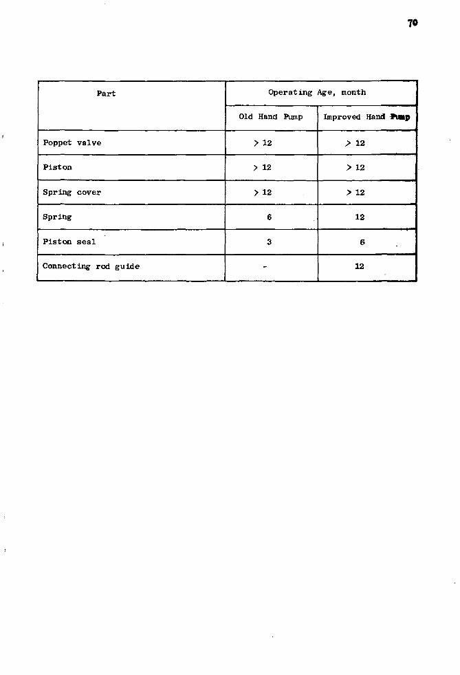
70
Part
Poppet v a l v e
P i s t o n
Spring cover
Spring
P i s t o n s e a l
Connecting rod gu ide
Operating Age, month
Old Hand Pump
> 12
> 12
> 12
6
3
-
Improved Hand tap
> 12
> 12
> 12
12
6
12
71
5. Comparison of Maintenance Data of Hand Pumps

72
TABLE B5 - 1
MINERAL RESOURCES DEPARTMENT HAND PUMP
Maintenance Period
1 week
2 month
4 month
8 month
1 week
3 month
Description
OLD HAND PUMP
- Grease all fulcra and
contact area
- Tighten all bolts and nuts
Inspect all parts of
hand pump installed upper
ground level.
Inspect all parts.
Inspect all parts.
IMPROVED HAND PUMP
Grease all fulcra and
contact area
- Tighten all bolts and nuts
Inspect all parts of
hand pump installed upper
ground level.
Material Used
- Grease
- Damage bolt or nut was
replaced by the new
ones.
- Damage part was replaced
by the new ones.
- Parts would be replaced;
- bolts and nuts
- gasket and plunger cup
- Parts would be replaced;
all fulcrum pin
- coupling
- cylinder wire spring
- Grease
- Damage bolt of nut was
replaced by the new ones.
- Damage part was replaced
by the new ones.

73
Maintenance Period
6 month
12 month
Description
Inspect all parts
Inspect all parts
Material Used
- Parts would be replaced;
- bolts and nuts
- gasket and plunger cup
- all bushing
- circle bar spring
- Parts would be replaced;
- all fulcrum pin
- coupling
- connecting rod guide
- cylinder wire spring
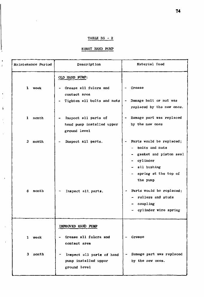
TABLE B5 - 2
74
KORAT HAND PUMP
Maintenance Period
1 week
1 month
3 month
6 month
1 week
3 month
, . , .
Description
OLD HAND PUMP:
- Grease all fulcra and
contact area
- Tighten all bolts and nuts
Inspect all parts of
hand pump installed upper
ground level
Inspect all parts.
Inspect all. parts.
IMPROVED HAND PUMP
- Grease all fulcra and
contact area
Inspect all parts of hand
pump installed upper
ground level
Material Used
Grease
- Damage bolt or nut was
replaced by the new ones.
- Damage part was replaced
by the new ones
- Parts would be replaced;
bolts and nuts
- gasket and piston seal
- cylinder
all bushing
spring at the top of
the pump
- Parts would be replaced;
- rollers and studs
- coupling
- cylinder wire spring
- Grease
- Damage part was replaced
by the new ones.
•
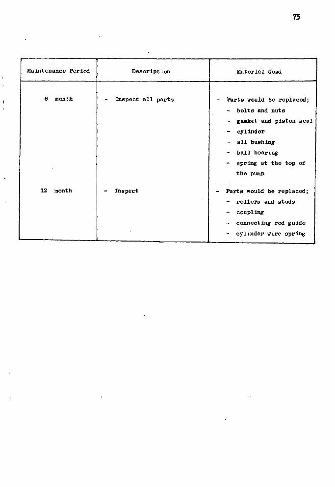
75
.
Maintenance Period
6 month
12 month
1 — _
Description
Inspect all parts
Inspect
Material Uesd
- Parts would be replaced;
- bolts and nuts
- gasket and piston seal
- cylinder
- all bushing
- ball bearing
- spring at the top of
the pump
- Parts would be replaced;
- rollers and studs
- coupling
- connecting rod guide
- cylinder wire spring

76
TABLE B5 - 3
ARD EQUIPMENT CONTROL DIVISION HAND PUMP
Maintenance Period
1 week
1 month
3 month
6 month
1 week
Description
OLD HAND PUMP
- Grease all fulcra and
contact area
- Tighten all bolts and
nuys
Inspect all parts of
hand pump installed
upper ground level.
Inspect all parts
Inspect all parts
IMPROVEMENT HAND PUMP
- Grease all fulcra and
contact area
- Tighten all bolts and
nuts.
Material Used
- Grease
- Damage bolt or nut was
replaced by the new ones
- Damage part was replaced
by the new ones.
- Parts would be replaced;
- bolts and nuts
- gasket and piston seal
- cylinder
- bushing
- Parts would be replaced;
studs or pins
- ball bearing
- coupling
- cylinder wire spring
- Grease
- Damage bolt all nut
was replaced by the
new ones.

78
•
»
6. Comparison of Total Cost of Hand Pumps
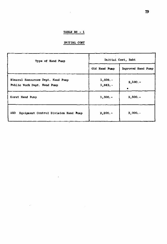
79
TABLE B6 - 1
INITIAL COST
Type of Hand Pump
Mineral Resources Dept. Hand Pump
Public Work Dept. Hand Pump
Korat Hand Pump
ARD Equipment Control Division Hand Pump
Initial Cost, Baht
Old Hand Pump
1,509.-
1,643.-
1,500.-
2,200.-
Improved Hand Pump
2,100.-
«
2,500.-
3,000.-

TABLE B6 - 2
OPERATING COST
Type of Hand Pump
Mineral Resources and Public Works
Department Hand Pumps
Korat Hand Pump
ARD Equipment Control Division Hand Pump
Operating Cost, Baht/month
Old Hand Pump
60
50
40
Improved Hand Pump
50
40
30

81
7. Comparison of Man-Hours for Dismantling and Insta l lat ion

8?
TABLE B7
COMPARISON OP MAN-HOURS FOR DISMANTLING AND INSTALLATION
Type of Hand Pump
Mineral Resources and Public Works
Department Hand Pumps
Korat Hand Pump
ARD Equipment Control Division Hand
Pump
Man-Hours Required for Dismantling
and installation/one time
Old Hand Pump
6
5
5
Improved Hand Pump
8
7
7
83
8. Comparison of Operational Eff ic iency
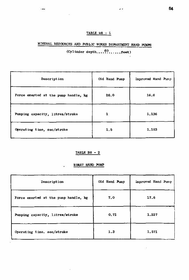
84
TABLE B8 - 1
MINERAL RESOURCES AND PUBLIC WORKS DEPARTMENT HAND PUMPS
(Cylinder depth....?? feet)
Description
Force exerted at the pump handle, kg
Pumping capacity, l i t r e s / s t r o k e
Operating time, sec /s troke
Old Rand Pump
26.0
w
1 . 5
Improved Hand Pump
16.6
1.136
1.193
TABLE B8 - 2
KORAT HAND PUMP
Description
Force exerted at the pump handle, kg
Pumping capacity, l i t r e s / s t r o k e
Operating time, sec /s troke
Old Hand Pump
7 . 0
0.71
1 . 3
Improved Hand Pump
17.6
1.227
1.571

TABLE B8 - 3
ABD EQUIPMENT CCNTROL DIVISION BAWD PUMP
Descrlpt ion
Force exerted at the pump handle, kg
Pumping capac i ty , l i t r e s / s t r o k e
Operating t ime, s e c / s t r o k e
Old Hand Pump
10.0
0,51
1.15
Improved Hand Pump
16.8
0.909
1.436

86
APPENDIX C
DATA COLLECT ION FORMS
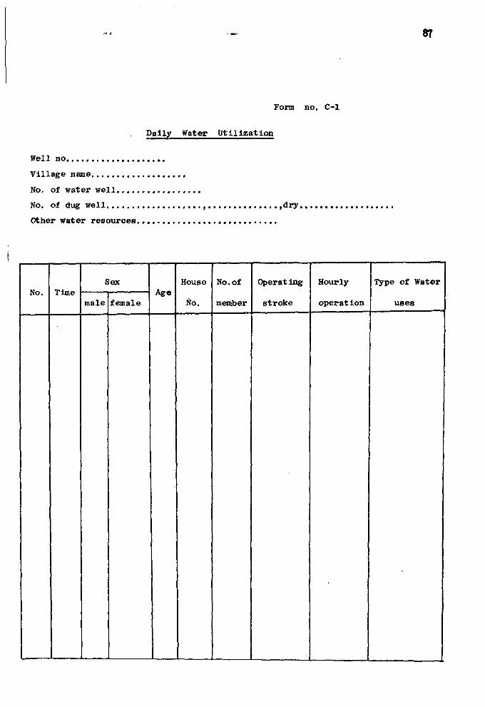
37
Form no. C-l
. Dally Water Utilization
Well no
Village name
No. of water well
No. of dug well , ,dry
Other water resources
No. Time Sex
male female Age
House
No.
No. of
member
Operat ing
stroke
Hourly
operat ion
Type of Water
uses
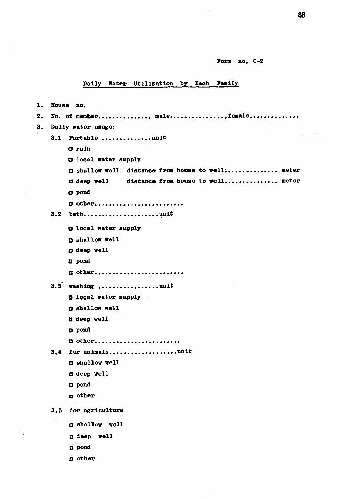
68
Form no. C-2
Dally Water Utilization by Each Family
House no.
No. of member male. ........ female
y Daily water usage:
3.1 Portable unit
O rain
O local water supply
a shallow well distance from house to well; meter
D deep well distance from house to well meter
O pond
a other
3.2 bath unit
O local water supply
O shallow well
• deep well
O pond
• other
3 .3 washing unit
0 local water supply
O shallow well
D deep well
O pond
a other
3.4 for animals unit
D shallow well
O deep well
D pond
0 other
3.5 for agriculture
0 shallow well
D deep well
0 pond
• other

89
Form no. C-3
Operatlag Time Record
No. of
Member
Time ( O'clock )
arrive begin t o operate f inished

90
Form no. C - 4
Installation Record
Well no No. of Test ing Group
Name of Village
Tarn Bon
Amphur
Changwat
Type of Hand Pump
Depth of Sett ing
Stat ic Water Level
Time Needed for Insta l la t ion
Well character is t ics
Ft .
Ft .
Man-Hours.

91
Form no. C-5
Repair Record
Well no
Date that damage occured
Date of commence repair
Date of completion
Damage found outside of hand pump before dismantle
1.
2.
3.
4 .
5.
Damage found inside after dismantle
1.
2.
3.
4 .
5.
Total days for repair
No. of man-hours
Cost of accessories

92
APPENDIX D
REVISED PARTS DRAWING

93
1. Revised Parts Details Drawing
Department of Mineral Resources Type.
94
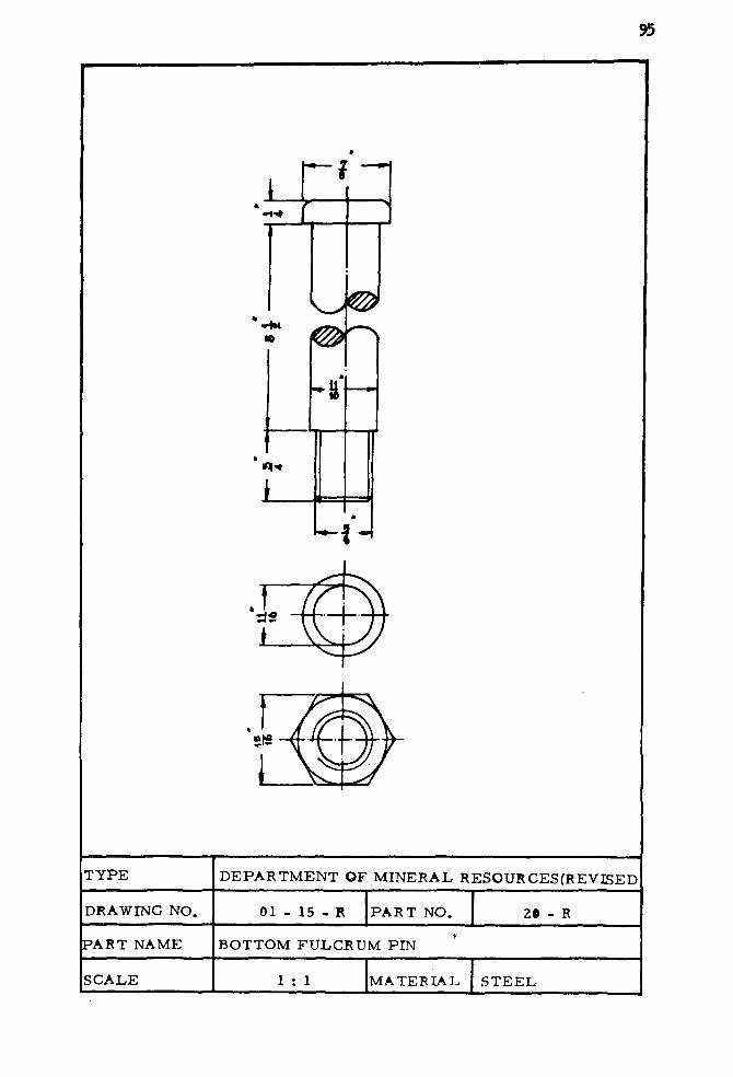
- i - *
*w
r-t -~i
u-H
T Y P E D E P A R T M E N T O F MINERAL RESOURCES(REVISED
DRAWING NO. 01 - 15 - R P A R T NO. 20 - R
PART NAME BOTTOM FULCRUM PIN
SCALE 1 : 1 M A T E R I A L S T E E L
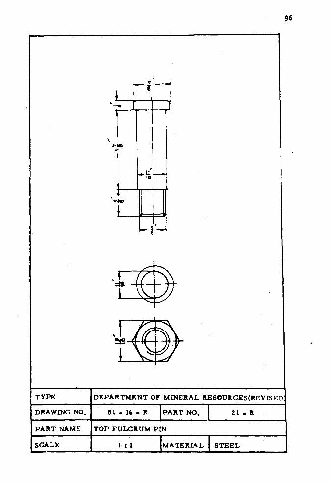
M B
r i
96
*M*>
TYPE DEPARTMENT OF MINERAL RESOURCES(REVI5ED
DRAWING NO. 01 - 16 - R PART NO. 21 - R
PART NAME TOP FULCRUM PIN
SCALE 1 : 1 MATERIAL STEEL

-i-*
Ma>
•Noo
9T
94
91
3 9
7
T Y P E D E P A R T M E N T O F MINERAL RESOURCES(REVISED)
DRAWING NO, 01 - 17 P A R T NO, 22 - R
P A R T NAME EYE P U M P PIN MATERIAL S T E E L
SCALE 1 : \ DRAWN By
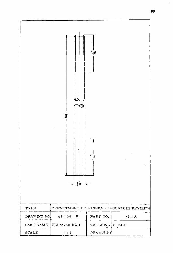
98
^9
*-*
TYPE D E P A R T M E N T OF MINERAL RESOURCES(R£VISED)
DRAWING NO 01 - 34 - R P A R T NO. 41 - R
PART NAME PLUNGER ROD MATERIAL S T E E L
SCALE 1 : 1 DRAW N B}
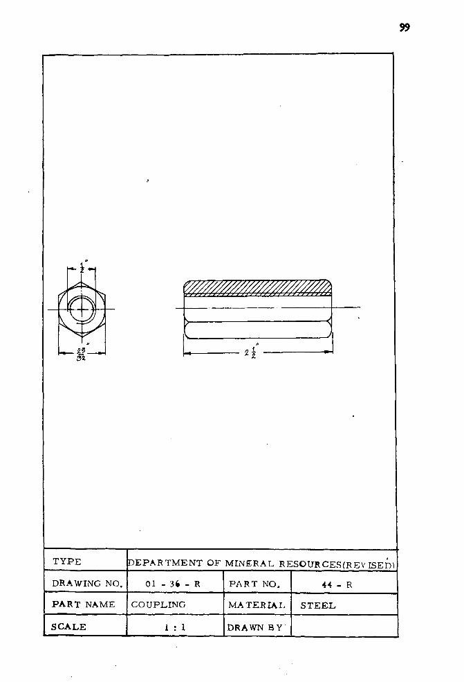
99
l-i-t
© S4
T Y P E D E P A R T M E N T OF MINERAL RESOURCES (REV B E D )
DRAWING NO. 01 - 3*
PART NAME COUPLING
P A R T NO.
MATERIAL
44 - R
S T E E L
SCALE 1 : 1 DRAWN BY

100
z2
J
Hk
T Y P E D E P A R T M E N T O F MINERAL RESOURCES(REVISED)
DRAWING NO. 01 - 37 - R P A R T NO. 45
P A R T NAME CENTERING CUIDi: MATERIAL BRASS
SCALE 1 : 1 DRAWN BY

101
1/»»»/»A
SIS
7ZZZZZ2ZZZZZ
- IS
T Y P E
DRAW ING NO.
P A R T NAME
SCALE
D E P A R T M E N T O F MINERAL RESOURCES(RE V BED)
01 - 31 - R P A R T NO. 4fc
P U M P HANDLE BUSH
1 : 1 MATERIAL BRASS

102
V///////////////////A
EiS
L W y W - V / W / z W / y / V
1 J
TYPE DEPARTMENT OF MINERAL RESOURCES (REVISED
DRAWONG NO 01 - 39 - R PART NO. 47
PART NAME FULCRUM LINK BUSH
SCALE 1 : 1 MATERIAL BRASS

103
B W
W77A
sis
TYPE D E P A R T M E N T O F MINERAL RESOURCES(REVISED)
DRAWING NO 01 - 40 - R P A R T NO. 4X
PART NAME CIRCLE BAR BUSHING
SCALk 1 : 1 MATERIAL BRASS

s»*
> — <
T Y P E D E P A R T M E N T O F MINERAL RESOURCES(REVISED)
DRAWING NO. 01 - 41 - R P A R T NO 4 *
P A R T NAME CIRCLE BAR LOCK NUT
SCALE 1 : 1 MATERIAL STANDARD

105
« • *
T Y P E D E P A R T M E N T O F M I N E R A L RESOURCES(REVISED)|
DRAWING NO, 01 - 42 - R P A R T NO. 58
P A R T NAME |CIRCLE BAR SPRING
SCALE 1 : 1 MATERIAL SPRING WIRE

m V/A-&
IA id
' !
- 4 « *
T Y P E D E P A R T M E N T O F MINERAL RESOURCES(REVISED)
DRAWING NO. 01 - 43 PART NO. 51
PART NAME GUIDE CIRCLE BAR BUSHING
SCALE I : 1 M A T E R I A L BRASS
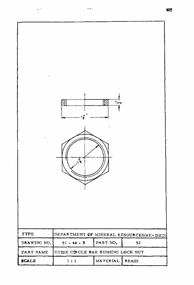
107
2 ,^- 1 *
' 8
£
•»
I ' • - * .
f
T Y P E D E P A R T M E N T OF MINERAL RESOURCES(KE V ISED)
DRAWING NO. 0 1 - 4 4 P A R T NO. 52
P A R T NAME GUIDE CIRCLE BAR BUSHING LOCK NUT
SCALE 1 : 1 M A T E R I A L BRASS

» a -A *H
0^\
4 T
-i a
H
-n
fl-
'/38
1
TYPE D E P A R T M E N T OF MINERAL R E S O U R C E S ( F E V I ? E r
DRAWING NO. 01 - 45 - R P A R T NO. 53
PART NAME CIRCLE BAR MATERIAL S T E E L
SCALE 1 : 2 DRAWN BY

109
2. Revised Parts Details Drawing
Health Department Type or Korat Hand Pump.
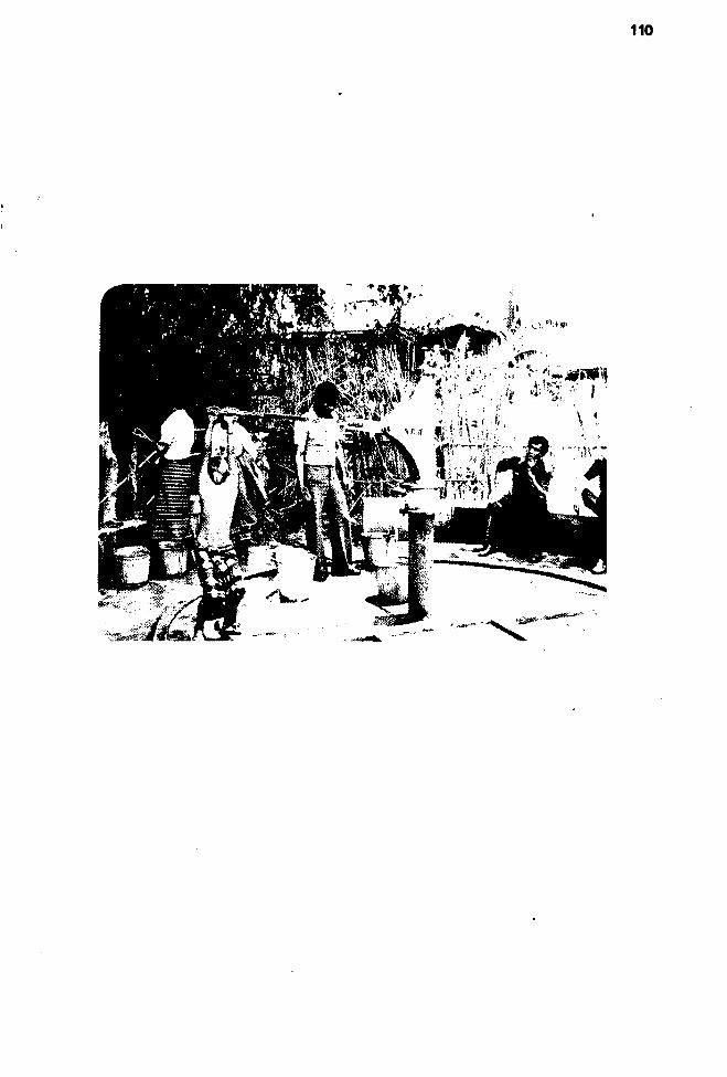
110
£.; ,*y-"*7ijJ'
• » J * « . . .
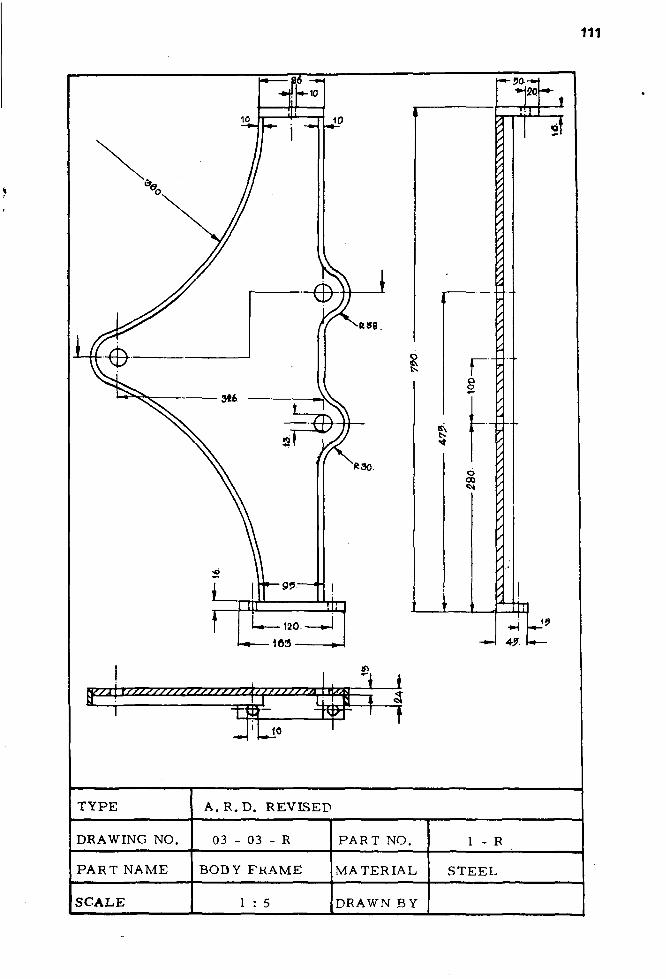
I
EZZ(3ZZZ2ZZZZZZZ2ZZZZZZ^2Z2ZZZZZaj:
»
n w JL_1
s
r o o
1 *
o 00
H20
7
4?. L—
T Y P E A. R . D . REVISED
DRAWING NO. 03 - 03 - R P A R T NO. 1 - R
P A R T NAME BODY F R A M E MATERIAL S T E E L
SCALE 1 : 5 DRAWN BY
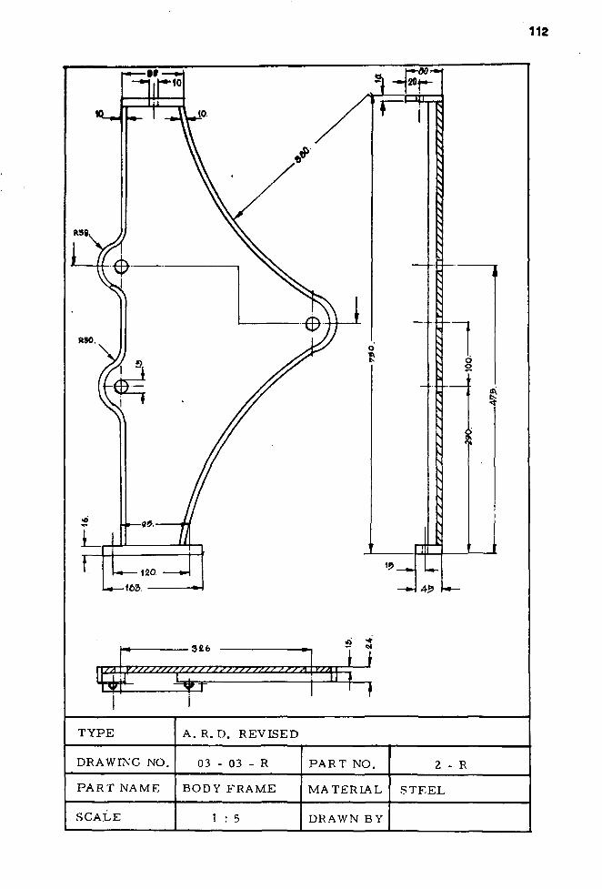
326
/A \ysss;ssss/sjs/ss>;>>>/>//-7-rx
^T" 33=}
« 3 Li
TYPE A. R. D. REVISED
DRAWING NO. 03 - 03 - R P A R T NO.
P A R T NAME BODY FRAME MATERIAL S T E E L
SCALE 1 : 5 DRAWN BY
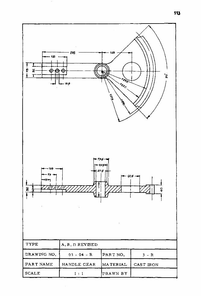
ff
•10 J A70
ii 2
f-90?—4
2L o
T Y P E A . R . D REVISED
DRAWING NO. 03 - 04 - R P A R T NO. 3 - R
P A R T NAME HANDLE GEAR MATERIAL CAST IRON
SCALE 1 : 1 PRAWN BY

114
h—82
\ - ~
\A
TYPE ACCELERATED RURAL DEVELOPMENT OFFICE
DRAWING NO. 03 - 06 PART NO. 21
PART NAME HANDLE MATERIAL STEEL
SCALE 1 : 2 DRAWN BY
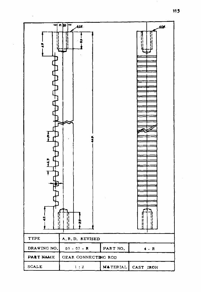
11.5
=
I * * *
u
fi%
A . R . D . REVISED
03 - 07 PART NO.
P A S T NAME GEAR CONNECTING ROD
MATERIAL CAST IRON

116
J
T
o »
TYPE A . R . D . REVISED
DRAWING NO. 03 - OS - R PART NO. 5 - R
PART NAME CONNECTING R O p
SCALE 1 : I MATERIAL S T E E L
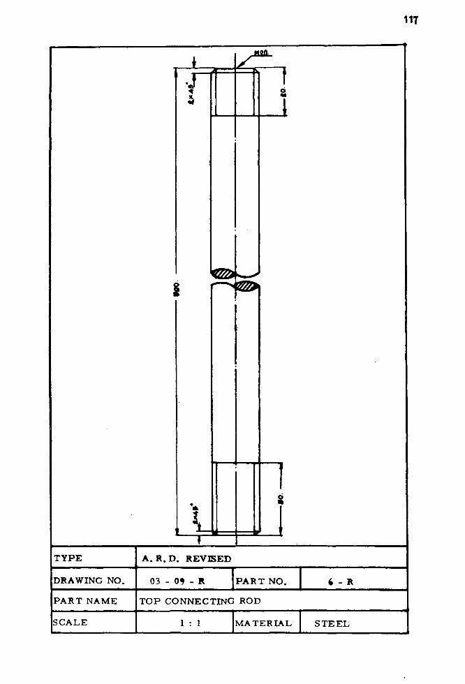
117
•J
s
1
TYPE A . R . D . REVISED
DRAWING NO. 03 - 0* - R P A R T NO.
P A R T NAME T O P CONNECTING ROD
SCALE 1 : 1 MATERIAL S T E E L

118
TYPE
DRAWING NO.
PART NAME
SCALE
A . R . D . REVISED
03 - 11 - R
P U M P BASE
1 : 2 . 5
P A R T NO.
M A T E R I A L
DRAWN BY
1 - R
CAST IRON

119
J o • <
{
—w
v//
y/^m
•m 90.
/A
//t
— * •
8k
T Y P E A . R . D . REVISED
DRAWING NO. 03 - 14 - R P A R T NO. 11
PART NAME O L L E R MATERIAL S T E E L
SCALE 1 : 1 DRAWN BY

120
J
^~tLf —-
I | t
TYPE A . R . D . REVISED
DRAWING NO. 03 - 15 PART NO. 12 - R
PART NAME BUSH MATERIAL STEEL
SCALE 1 : 1 DRAWN BY

121
3. Revised Parts Detai l s Drawing
ARD Equipment Control Divis ion Type.
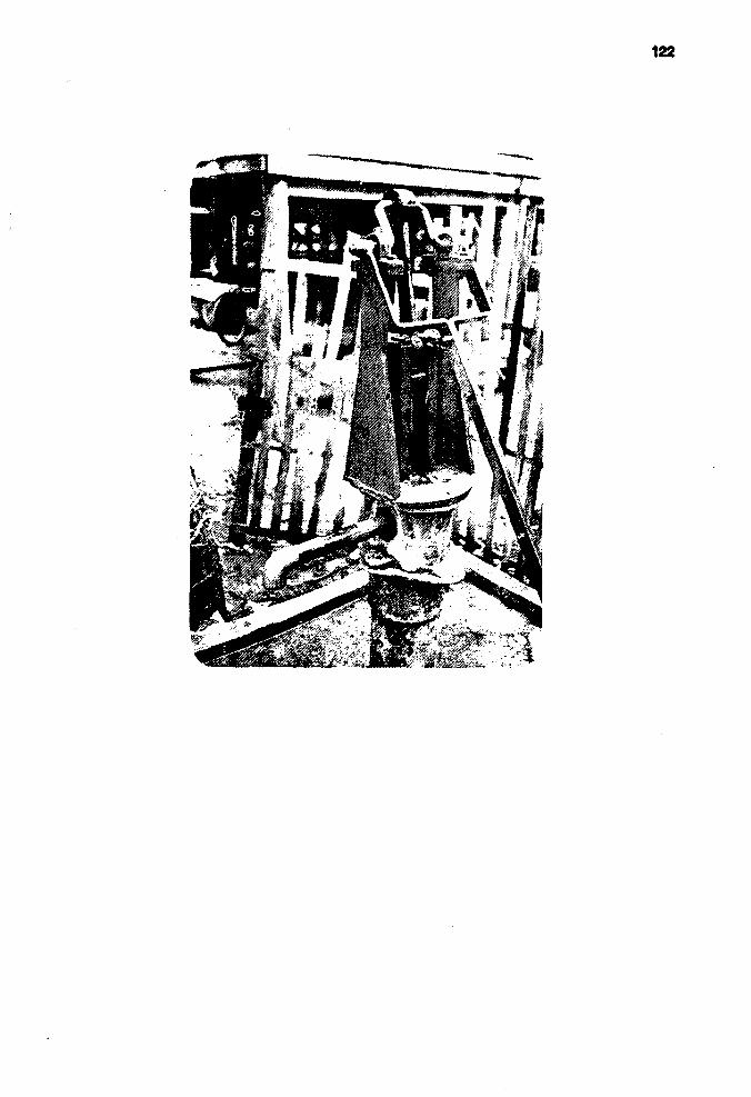
122

TYPE A P T E Q U I P M E N T CONTROL DIVISION
DRAWING NO. 04 - 01 P A R T NO.
P A R T NAME HAND P U M P ASSEMBLY ( F R O N T VIEW )
SCALE DRAWN BY

ay^
T Y P E ARD E Q U I P M E N T CONTROL DIVISION
DRAWING NO. 04 - 02 P A R T NO.
P A R T NAME HAND P U M P ASSEMBLY(SIDE VIEW)
SCALE 1 : 5 DRAWN BY

125
vi
i •1«
n
«KI«
u
«• *
i ̂N
—(>
- < •
¥ M-
TYPE ARD E Q U I P M E N T CONTROL DIVISION
DRAWING-NO. 04 - 03 P A R T NO.
PART NAME P U M P HANDLE MATERIAL S T E E L
SCALE 1 : 2 . 5 DRAWN BY

126
TYPE ARD EQUEPNENT CONTROL DIVISION
DRAWING NO. 04 -04 PART NO.
PART NAME CRANK SHAFT MATERIAL STEEL
SCALE 1 : 2 DRAWN BY

BK
wzzzzzz w
}z/z////A M $r
TYPE ARD EQUIPMENT CONTROL DIVISION
DRAWING NO. 04-05 PART NO.
PART NAME CONNECTING ROD
1 SCALE 1 : 2 MATERIAL! STEEL

128
0
\
* *"
i — \r — 16
-—*20i
-V A
\
N
i»r~'
»
)
^
o I
} s
\ >
T Y P E ARD E Q U I P M E N T CONTROL, DIVISION
DRAWING NO. 04 - 06 P A R T NO.
P A R T NAME U - JOINT PIN MATERIAL S T E E L
SCALE 1 : 1 DRAWN BY
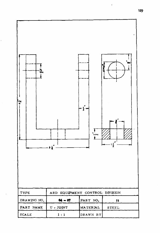
129
I
I '
- -
1 •5.
_i
. . 3 » ' -
—
* • — 1 - . -t
1 1 1 1 1 _
rt-\
'A a z
TYPE ARD EQUIPMENT CONTROL DIVISION
DRAWING NO. «4-0T PART NO. 11
PART NAME U - JOINT MATERIAL STEEL
SCALE 1 : 1 DRAWN BY
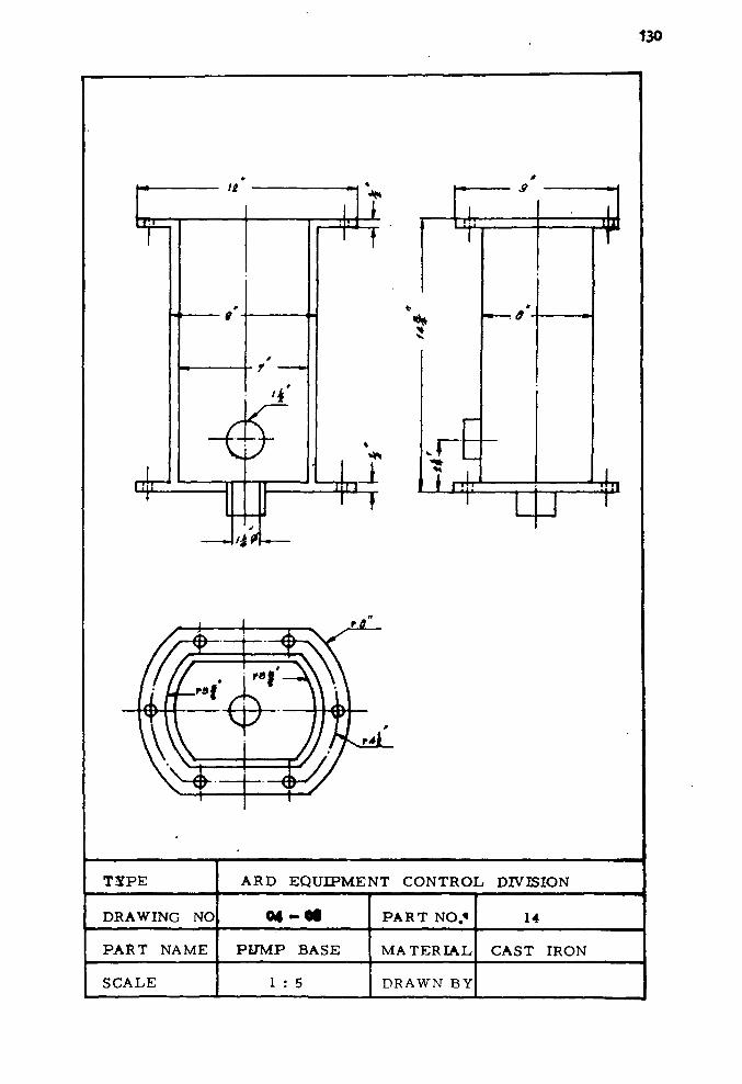
130
It
T
rrp \
0
r v
-J/4
•
j
- * i \
^ T
vL—
M I T7 f
5
4r
s JLnt
*
in
T3TPE ARD EQUIPMENT CONTROL DIVISION
DRAWING NO <* -©• PART NO.« 14
PART NAME PUMP BASE MATERIAL CAST IRON
SCALE 1 : 5 DRAWN BY

131
APPENDIX E
WORKING GROUP AND ACKNOWLEDGEMENT

LIST OF WORKING GROUP
1. Mr. Virasak Kraivichien, M.S.M.E., Chief of Equipment Control
Division, ARD Office, Bangkok, Thailand.
2. Mr. Suvit Kaneckul, B.S.M.E. , Mechanical engineer, ARD
Field Operations center, Khon Kaen, Thailand.
3. Miss Payom Mukdeeprom, M.S. I.E., Mechanical Engineer, Equipment
Control Division, ARD Office, Bangkok, Thailand.
4. Miss Suranee Punnikul, B.S.M.E., Mechanical Engineer, Equipment
Control Division, ARD Office, Bangkok, Thailand.
5. Technicial Group, ARD Field Operations Center, Khon Kaen,
Thailand.
Consultants
1. Mr. Vithu Vibhatapathya, B.S.M.E., Deputy Secretary Geueral
of ARD Office, Bangkok, Thailand.
2. Mr. Prasit Wilailuksn, M.S.C.E., Director of ARD. Field
Operations Center, Khon Kaeu, Thailand.
3. Mr. Pricha Chulavatchana, M.S (San.Eng.) National Officer,
UNICEF, Bangkok, Thailand.
Acknowledgement
The ARD wishes t o express the apprec ia t ion t o t he UNICEF
for making t h i s repor t pos s ib l e . We are p a r t i c u l a r l y indepted t o
Mrs. Cather ine Deeks, UNICEF Senior Programme Officer for her
a s s i s t a n c e . Mr. Damrongsakdi Nit iparachon and Miss J a r i n e e Sophonpit
are thanked for t h e i r comments and reviews of t h i s r e p o r t .
And we would l i k e t o thanks o f f i ce r s from Mineral Resources
Department, Minis t ry of I n d u s t r i a l and Pobl ic Works Department,
Ministry of I n t e r i o r , for supplying e x i s t i n g hand pump fo r t h e
t e s t i n g programme, F i n a l l y , we a l so w i s t t o express our thanks t o
a l l p r i n t e r s in t he ARD p r i n t e r ' s shop fo r p r i n t i n g t h i s r e p o r t .

REFERENCE?
NIDA(1978) : Evaluation on National Rural Water Supply Programme,
published in Thai version under the jo in t sponsor
ship of NESDB and UNICEF.
NESDB(1977) : Report of a Workshop on National Rural Water Supply
Programme, held at Khon Kaen, April 7 - 10, 1977
in co-operation with UNICEF.
NESDB(1978) : Report_of.Workshop 22_Handpump_anilJDrilling^^lg,
held at Chiengmai, January 18 ,- 20, 1978, in
co-operation with IDRC.
John & Showcross (1978) : Handpump Maintenance, interim report
t o International Reference Centre for community
water supply.