improvement of tuning fork gyroscope drive-mode
TRANSCRIPT
International Journal of Electrical and Computer Engineering (IJECE)
Vol. 6, No. 6, December 2016, pp. 2716~2729
ISSN: 2088-8708, DOI: 10.11591/ijece.v6i6.12094 2716
Journal homepage: http://iaesjournal.com/online/index.php/IJECE
Improvement of Tuning Fork Gyroscope Drive-mode
Oscillation Matched using a Differential Driving Suspension
Frame
Thang Nguyen Van1, Tran-Duc Tan
2, Hung Vu Ngoc
3, Trinh Chu Duc
4
1Broadcasting College I, Radio the voice of Vietnam 2,4University of Engineering and Technology, Vietnam National University, Hanoi, Vietnam
3University of Science and Technology, Hanoi, Vietnam
Article Info ABSTRACT
Article history:
Received Jun 5, 2016
Revised Sep 30, 2016
Accepted Oct 13, 2016
This paper presents a novel design of a vibration tuning fork gyroscope
(TFG) based on a differential driving suspension coupling spring between
two gyroscopes. The proposed TFG is equivalent to a transistor differential
amplifier circuit. The mechanical vibrations of driving frames are, therefore,
well matched. The matching level depends on stiffness of spring. When three
various TFG structures respond to differential stiffness of spring, their the
driving frame mechanical vibration is well matched in case the input
excitation driving differential phase is less than 3.5, 2.5, and 4,
respectively. The fabricated tuning fork gyroscope linearly operates in the
range from -200 to +200 degree/s with the resolution of about
0.45 mV/degree/s.
Keyword:
Differential driving suspension
coupling spring
Differential MEMS gyroscope
Electronics differential
amplifier
Vibration tuning fork gyroscope
Copyright © 2016 Institute of Advanced Engineering and Science.
All rights reserved.
Corresponding Author:
Thang Nguyen Van,
Faculty of Electronics and Communications Technology,
Broadcasting College 1,
136 Quy Luu Road, Phu Ly City, Ha Nam Province, Vietnam.
Email: [email protected]
1. INTRODUCTION
Nowadays, micromachined gyroscope in general and vibratory tuning fork gyroscope in particular
are very popularly utilized in reality [1-4]. In many applications, performance and operation of gyroscope
and TFGs are affected by a wide variety of changing environmental conditions such as pressure, ambient
vibrations, and temperature [5-7]. The robustness of sensors and beams to these external influences during
operation is critical for adequate performance [8].
All micromachined vibratory gyroscopes can be divided into two various types: Type I and
Type II [9]. The working principle of all of them is based on the Coriolis force produced by rotation of the
gyroscope causing a transfer of energy between two of the gyroscope’ modes of vibration. A new MEMS
gyroscope design can improve performance of angle measurement implemented in [10] while the other is
developed to either upgrade the performance or reduce the cost [11]. Besides that, there are also some other
optimal MEMS gyroscope structures such as micromachined ring or disk designed to obtain the better
precision [12-13]. A detailed analysis of the cause of vibration-induced error is implemented to understand
the vibration effects on ideal tuning fork gyroscopes [5]. The article points out three major causes of error
that arise from capacitive nonlinearity at the sense electrode, asymmetric electrostatic forces along sense
direction at the drive electrodes and asymmetric electrostatic forces along drive direction at the drive
electrodes. Reference [14] utilizes symmetrically decoupled tines with drive-mode synchronization and
sense-mode coupling structures. The levered drive-mode mechanism structurally forces the anti-parallel, anti-
phase drive-mode motion and eliminates the lower frequency spurious mode presented in conventional
IJECE ISSN: 2088-8708
Improvement of TFG Drive-mode Oscillation Matched Using a Differential Driving … (Thang Nguyen Van)
2717
tuning fork gyroscopes. The linearly coupled, momentum and torque balanced anti-phase sense-mode
reduces dissipation of energy through the substrate yielding ultra-high quality factors. A completely
symmetric, dynamically balanced quadruple mass gyroscope with a 2.2 kHz operational frequency illustrated
virtually identical drive and sense mode Q-factors of 0.9 million. The most important thing in the quadruple
mass design is to be expected to enable rate-integrating mode of operation due to its unique combination of
low energy dissipation and isotropy of both the resonant frequency and damping [15]. A novel micro-
machined dual-axis TFG could effectively minimize the undesired lateral motion and ensure the anti-phase
resonant mode of the two vibration frames [16]. A capacitive-type tuning fork micro-gyroscope is developed
in [17]. A novel quad mass gyroscope in [18-19] is designed and fabricated in order to increase the gap
between two resonance modes and reduce the energy transfer between the two modes, allowing for
robustness to external acceleration.
However, there are not any studies mentioning and analyzing about the importance and the role of
differential driving suspension coupling spring and suspension beams between two gyroscopes in
conventional tuning fork gyroscope.
This paper presents a novel design of a vibration tuning fork gyroscope based on a differential
driving suspension coupling spring between the two driving frames of TFGs. Therefore, the mechanical
vibrations of driving frames are well matched. It means that the differential driving suspension coupling
spring can compensate differential phase shift of two input excitation driving signals allowing the TFG to
work normally.
2. TUNING FORK GYROSCOPE AND DIFFERENTIAL AMPLIER
2.1. Gyroscope
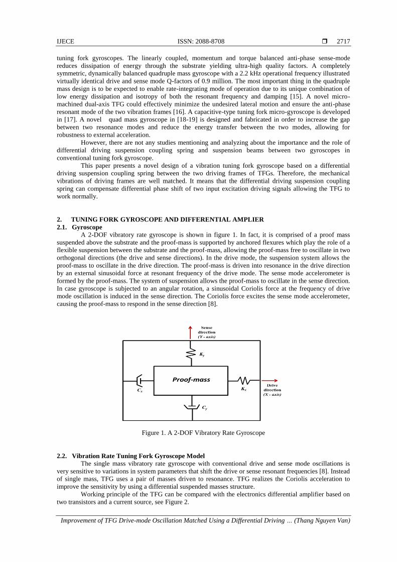
A 2-DOF vibratory rate gyroscope is shown in figure 1. In fact, it is comprised of a proof mass
suspended above the substrate and the proof-mass is supported by anchored flexures which play the role of a
flexible suspension between the substrate and the proof-mass, allowing the proof-mass free to oscillate in two
orthogonal directions (the drive and sense directions). In the drive mode, the suspension system allows the
proof-mass to oscillate in the drive direction. The proof-mass is driven into resonance in the drive direction
by an external sinusoidal force at resonant frequency of the drive mode. The sense mode accelerometer is
formed by the proof-mass. The system of suspension allows the proof-mass to oscillate in the sense direction.
In case gyroscope is subjected to an angular rotation, a sinusoidal Coriolis force at the frequency of drive
mode oscillation is induced in the sense direction. The Coriolis force excites the sense mode accelerometer,
causing the proof-mass to respond in the sense direction [8].
Figure 1. A 2-DOF Vibratory Rate Gyroscope
2.2. Vibration Rate Tuning Fork Gyroscope Model
The single mass vibratory rate gyroscope with conventional drive and sense mode oscillations is
very sensitive to variations in system parameters that shift the drive or sense resonant frequencies [8]. Instead
of single mass, TFG uses a pair of masses driven to resonance. TFG realizes the Coriolis acceleration to
improve the sensitivity by using a differential suspended masses structure.
Working principle of the TFG can be compared with the electronics differential amplifier based on
two transistors and a current source, see Figure 2.

ISSN: 2088-8708
IJECE Vol. 6, No. 6, December 2016 : 2716 – 2729
2718
Figure 2. The Electronics Differential Amplifier Basing on Two Transistors and a Current Source
In Figure 2, the differential pair amplifier is formed from the same name two transistors, where their
emitters are connected together. The shared emitter node is fed from a constant current source. The two base
inputs can be applied a differential input signal and the two outputs from the collectors remain balanced.
As a transistor amplifies the current flowing between base and emitter, it follows that the current
flowing in the collector circuit of the first transistor is proportional to the difference between the two inputs.
However, since the circuit is totally symmetrical, the element can be viewed either as an amplifier or as an
emitter follower, understanding does not depend on which role you assign to which device. The common-
mode rejection ratio (CMRR) of the differential amplifier is linearly related on the current source resistance
Re [20], whose value is ideally infinite. Therefore, in general, the CMRR parameter of a differential amplifier
is extremely large in comparing with a single stage amplifier. The CMRR is up to hundred thousand or even
more in some cases. Hence, the differential signal between the two inputs is much amplified and the common
signal is rejected.
Based on the working principle of the electronic differential amplifier, a TFG with differential
suspended driving masses is proposed (see Figure 3).
Figure 3. TFG with two differential suspended driving masses
In this structure, two driving masses are hanged on Kx springs. They allow driving masses to
oscillate only on the x-axis. The diamond frame with two Ky springs play a role as the current source on the
electronic amplifier. By using this diamond suspension, the two driving masses oscillate with same amplitude
but phase reversal. The proposed TFG, therefore, improves the sensitivity and much rejects the common-
mode noise from both driving and sensing sections.

IJECE ISSN: 2088-8708
Improvement of TFG Drive-mode Oscillation Matched Using a Differential Driving … (Thang Nguyen Van)
2719
3. DIFFERENTIAL DRIVING OSCILLATED TFG DESIGN
Figure 4 shows 2-DOF design of a proposed single gyroscope. The driving frame is suspended on
the x-axis springs. Capacitive actuator drives the frame to oscillate on driving resonant frequency. The
sensing mass is hanged on the driving frame by using two y-axis springs. In case of having excited driving
signals, the driving frame oscillates along the x-axis. When gyroscope is effected by ω angular rate, the
sensing frame oscillates along the y-axis thanks to two ellipse shape y-axis springs.
The driving oscillation is excited by applying a voltage to capacitor pairs. In the case of driving
function simulation, a mechanic force can be directly applied to drive comb frames.
In this work, the designed parameters of the single gyroscope are shown in the table 1. Several
eigenfrequencies are listed in the Table 2. The first oscillation mode with frequency of 13544.7 Hz is the
driving resonant oscillation one. Therefore, the driving proof-mass always obtains the maximum amplitude
displacement when applying this resonant frequency as the excited signal. The rest modes in the Table 2 are
unwanted driving and sensing oscillations. Mass of driving proof-mass (including of 0.9408×10e-11 kg
sensing proof-mass) is 0.5452×10e-7 kg. The stiffness of drive mode springs Kd= 347 N/m (including eights
springs) and the stiffness of sense mode springs Ks = 540 N/m (including two ellipse shape springs).
Figure 4. The Proposed Gyroscope: (1) Drive Springs, (2) Sense Springs, (3) Drive Capacitor Pairs,
(4) Drive Comb Frame
Table 1. The Proposed Gyroscope Structure Parameters Parameter Symbol Value
Real gyroscope height H 1754 µm
Real gyroscope width W 1644 µm
Device thickness t 30 µm
Outer frame height hdpm 1200 µm Outer frame width wdpm 1300 µm
Inner frame height hspm 840µm
Inner frame width wspm 940 µm Drive sub-suspension beam height h1 190 µm
Drive main suspension beam height h2 260 µm
Drive suspension beam width w1 6 µm Anchor size w2 × h3 40 µm × 40 µm
Number of drive comb frames 8
Drive comb frame height h5 200 µm Drive comb frame width w3 25 µm
Number of comb fingers in a drive comb frame 15
Drive comb finger size w4 × h4 50 µm × 3 µm Drive comb finger gap 2.5 µm
Gap between two comb fingers in the same frame g 8 µm
Drive finger overlap length ldfo 10 µm Ellipse 1 sense suspension beam size a1 × b1 150 µm × 20 µm
Ellipse 2 sense suspension beam size a2 × b2 144 µm × 14 µm
Drive mass md 0.5452 × 10⁻⁷ Kg Sense mass ms 0.9408 × 10⁻¹¹ Kg
Drive mode stiffness Kd 347 N/m
Sense mode stiffness Ks 540 N/m

ISSN: 2088-8708
IJECE Vol. 6, No. 6, December 2016 : 2716 – 2729
2720
Table 2. Several Oscillation Modes of Proposed Gyroscope Oscillation modes Frequency (Hz)
First (driving mode) 13544.7 Second 62268.7
Third 106921.8
Fourth 140865.5
This paper introduces a differential suspension structure which allows two driving proof-masses to
create mechanic differential displacement along the x-axis. The suspension structure is shown in figure 5 and
the designed parameters are listed in the table 3. The eight anchors constrain structure to move along y-axis
only. The x-axis stiffness is 121 N/m and the y-axis stiffness is 2314 N/m.
Figure 5. The structure of Differential Driving Suspension Coupling Spring
Table 3. The Designed Parameters of the Differential Driving Suspension Coupling Spring Parameter Value
R1 Width × Height: 132 µm × 100 µm R2 Width × Height: 70 µm × 20 µm
R3 Width × Height: 60 µm × 600 µm
R4 Width × Height: 60 µm × 20 µm R5 Width × Height: 60 µm × 80 µm
R6 Width × Height: 500 µm × 6 µm
R7 Width × Height: 200 µm × 6 µm
Total size Width × Height: 1000 µm × 1700 µm
Rotation angle of R3 30 degree Anchor size Width × Height: 40 µm × 40 µm
Structure thickness 30 µm
x-axis stiffness 121 N/m y-axis stiffness 2314 N/m
Two single gyroscopes are linked by the differential driving suspension coupling spring to form
proposed tuning fork gyroscope (see figure 6). This design constrains the two top and bottom corners A and
B moving along y-direction only thanks to anchors. The two rest corners C and D are connected to the two
driving frames. When having excited driving signals with the same amplitude but phase reversal put in two
single gyroscopes, two driving frames will also move with the same amplitude but phase reversal. Thanks to
the differential driving suspension coupling spring, the oscillation of two driving frames is always
compensated each other. If appearing excited driving signals are phase mismatch (non-phase reversal), the
differential driving suspension coupling spring will compensate the driving oscillation like the electronic
differential amplifier. Therefore, the mismatched oscillation components are eliminated and the matched ones
are amplified. In the special case, the excited signal is only applied in the left or the right driving frame of the
gyroscope, the TFG still works normally due to the differential driving suspension coupling spring
suspension girder structure. This proposed structure will deliver driving oscillation to both the driving frames

IJECE ISSN: 2088-8708
Improvement of TFG Drive-mode Oscillation Matched Using a Differential Driving … (Thang Nguyen Van)
2721
thanks to its symmetrical design. However, oscillation amplitude of the two driving frames of the gyroscope
is smaller when both two driving frames are excited.
In this the proposed TFG, the drive mode stiffness of whole system KdTFG = 1700 N/m. The
outermost device area is 4000 µm × 1900 µm with 30 µm thick device layer. Materials used in this design
and simulation are polysilicon and air. Where, the TFG is made by polysilicon and surrounding by air.
Figure 6. Design of the Proposed Tuning Fork Gyroscope. Two Driving Frame are Connected Together by a
Differential Driving Suspension Coupling Spring
As mentioned in section 2.2, the proposed TFG improves the sensitivity and much rejects the
common-mode noise from both driving and sensing sections. Hence, the particular purpose of this study is to
demonstrate that the two single gyroscopes correspond to the two BJT common emitter amplifiers and the
differential driving suspension coupling spring corresponds to the constant current source in the electronic
differential amplifier. The diamond coupling spring can compensate the differential phase of two driving
excited signals. It means that when two excited signals applied into driving comb frames of two gyroscopes
are differential to a certain value, the differential phase of mechanical oscillation of two driving frames is still
constant. The common vibration mode between the two driving frames is ignored when the differential
vibration mode is much amplified.
Figure 7 shows a SEM picture of fabricated devices based on SOI substrate and Deep-RIE silicon
etching with one mask fabrication process.
Figure 7. A SEM Picture of Fabricated Gyroscope
4. SIMULATION
Whole designed and simulation processes are implemented in a finite element modeling software
COMSOL MULTIPHYSICS 4.4 (COMSOL Inc.). This software can be used in a lot of application areas
such as Microelectromechanical systems (MEMS); Structural mechanics; heat transfer; Microfluidics etc.
Physics interfaces in COMSOL allow performing various types of studies including: stationary and
ISSN: 2088-8708
IJECE Vol. 6, No. 6, December 2016 : 2716 – 2729
2722
time-dependent (transient) studies; linear and nonlinear studies; eigenfrequency, modal, and frequency
response studies.
Materials utilized in this work are polysilicon and air. Excited signals can be force (N) or voltage
potentials (V) with various kinds of waveform such as sinusoidal, triangular, trapezoid. However, in order to
implement and simulate faster and simpler, instead of voltage potentials, a force function is directly applied
to the driving frame. Eigenfrequencies; stiffness; displacement of single gyroscope, differential driving
suspension coupling springs and the TFG are then simply extracted from simulation results.
5. RESULTS AND DISCUSSION
Before demonstrating that the proposed TFG has differential phase compensation ability between
two input excited signals, it needs to build some TFG architectures corresponding to various stiffness of the
differential driving suspension coupling spring. The main purpose of building various architectures is to find
a certain differential phase value of two input excited driving signals that the proposed TFG can compensate.
However, in order to obtain maximum displacements of drive proof-mass and sense proof-mass, it
needs to use the most suitable frequency in the excited signal equations. In this case, it is the driving resonant
frequency of the TFG. This frequency can be found via finite element method in Comsol Multiphysics
software version 4.4 (Study/Study steps/Eigenfrequency/Eigenfrequency).
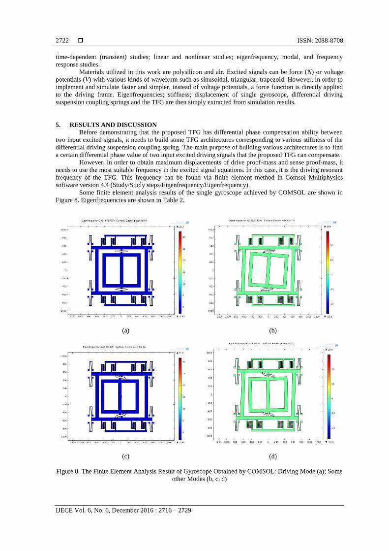
Some finite element analysis results of the single gyroscope achieved by COMSOL are shown in
Figure 8. Eigenfrequencies are shown in Table 2.
(a)
(b)
(c)
(d)
Figure 8. The Finite Element Analysis Result of Gyroscope Obtained by COMSOL: Driving Mode (a); Some
other Modes (b, c, d)

IJECE ISSN: 2088-8708
Improvement of TFG Drive-mode Oscillation Matched Using a Differential Driving … (Thang Nguyen Van)
2723
In this simulation, the stiffness of the differential driving suspension coupling spring between two
gyroscopes is changed to get the optimal value. Specifically, the heights of the coupling suspension beam R6
in Figure 8 of structure 1, 2, 3 are 6 µm, 4 µm, 12 µm, respectively while the rest parameters of structures are
unchanged.
Some finite element analysis results of the first proposed TFG (structure 1) achieved by COMSOL
are shown in Figure 9 (the similar way is implemented with the second and the third TFGs). Some oscillation
modes of three structures are shown in the Table 4.
(a)
(b)
(c)
(d)
Figure 9. The Finite Element Analysis Result of TFG Structure 1 Obtained by COMSOL: Driving Mode (a);
other Modes (b, c, d)
Table 4. Lowest Driving Related Oscillation Modes of Three TFG Structures
Modes Frequency (Hz)
Structure 1 Structure 2 Structure 3
First (Driving mode) 21397.9 21184.7 21751.2 Second 44446.8 44227.6 44801.3
Third 63436.5 63427.9 63447.1
Fourth 65032.2 65020.9 65049.6
The parameters in the table 4 show that the stiffer the differential driving suspension coupling spring
is, the higher the driving consonant frequency of TFG is and vice versa. Driving resonant frequency of the
first structure is shown in Figure 10. During the simulating process, the structures have the same mesh
settings: sequence type is physics-controlled mesh and element size is extremely coarse. The structure is
designed by polysilicon material and assumed to be immersed in air.
ISSN: 2088-8708
IJECE Vol. 6, No. 6, December 2016 : 2716 – 2729
2724
The two driving excitation signals are applied to the driving combs having formulas:
( ) (1)
( ) (2)
where f1 signal is put in eight driving comb frames of gyroscope on the left and f2 signal is put in eight
driving comb frames of gyroscope on the right.
The process of simulating results is individually performed for each above structure. So, f
frequency in Equation 1 and Equation 2 is the driving eigenfrequency (the driving resonant frequency)
correspondent to each structure. For example, f = 21397.9 Hz is applied to structure 1. In the conventional
working principle of the tuning fork gyroscope, the f1 and f2 two excited signals are anti-phase. It means that
φ =180 degree.
Figure 10. Driving Resonant Frequency of the Proposed Architecture 1
However, in this study the excitation signal f1 is kept stable while f2 is changed with various φ phase:
180, 179.5, 179, 178.5, 178 etc. in a computing time of a specific structure.
The aim of changing φin f2 is to observe mechanical vibration differential phase of two driving
proof-masses in order to determine differential phase compensation ability of the proposed TFGs when
having the differential phase between two input excitation signals.
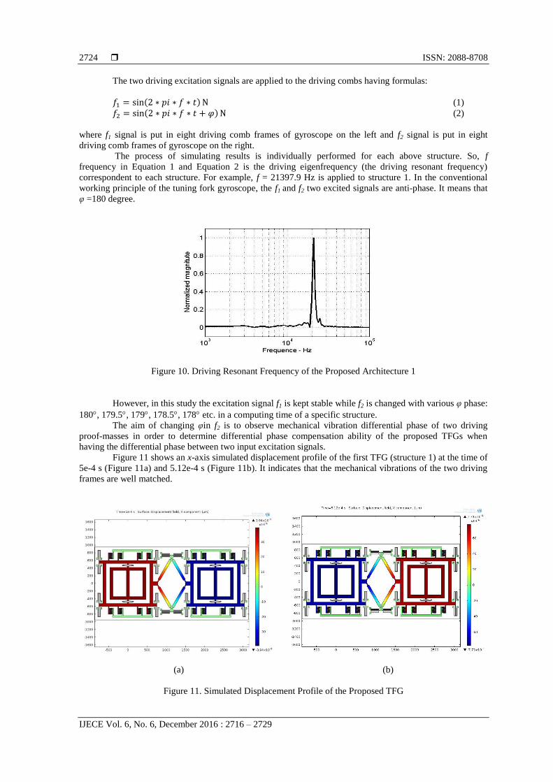
Figure 11 shows an x-axis simulated displacement profile of the first TFG (structure 1) at the time of
5e-4 s (Figure 11a) and 5.12e-4 s (Figure 11b). It indicates that the mechanical vibrations of the two driving
frames are well matched.
(a)
(b)
Figure 11. Simulated Displacement Profile of the Proposed TFG

IJECE ISSN: 2088-8708
Improvement of TFG Drive-mode Oscillation Matched Using a Differential Driving … (Thang Nguyen Van)
2725
Table 5 shows the relation between input excited signal differential phase φ and mechanical
displacement signal differential phase φ1 in three structures. These results are drawn in Figure 12.
Table 5. Relation between φ and φ1 φ 1
φ Structure 1 Structure 2 Structure 3
180°/0° 0 0 0
179.5°/0.5° 0 0 0
179°/1° 0 0 0 178.5°/1.5° 0 0 0
178°/2° 0 0 0
177.5°/2.5° 0 0 0 177°/3° 0 3.5 0
176.5°/3.5° 0 7.0 0
176°/4° 3.9 15 0 175.5°/4.5° 18.2 x 15.6
Unit: Degree
Figure 12. Mechanical Vibration Differential Phase between Two Driving Frames Versus Electrical Driving
Phase Difference
Above results shows that the mechanical vibration is well matched when the driving excitation
phase different is less than 3.5, 2.5 and 4 corresponding to structure 1, 2 and 3, respectively with driving
signal of 1 N amplitude and 0 N offset. The mechanical vibrations of two driving frames are not compensated
for the excited driving differential phase more than 3.5, 2.5 and 4 corresponding to structure 1, 2 and 3. In
this case, the mechanical vibration is fully dominated by the excited signal. Basing on the results of the three
structures, the structure 3 is the best one thanks to the wide range of the excited driving differential phase up
to 4. However, the resonant frequency of this structure is also the highest (see Table 4).
Figure 13. Driving Proof-Mass Displacement of the Proposed TFG
ISSN: 2088-8708
IJECE Vol. 6, No. 6, December 2016 : 2716 – 2729
2726
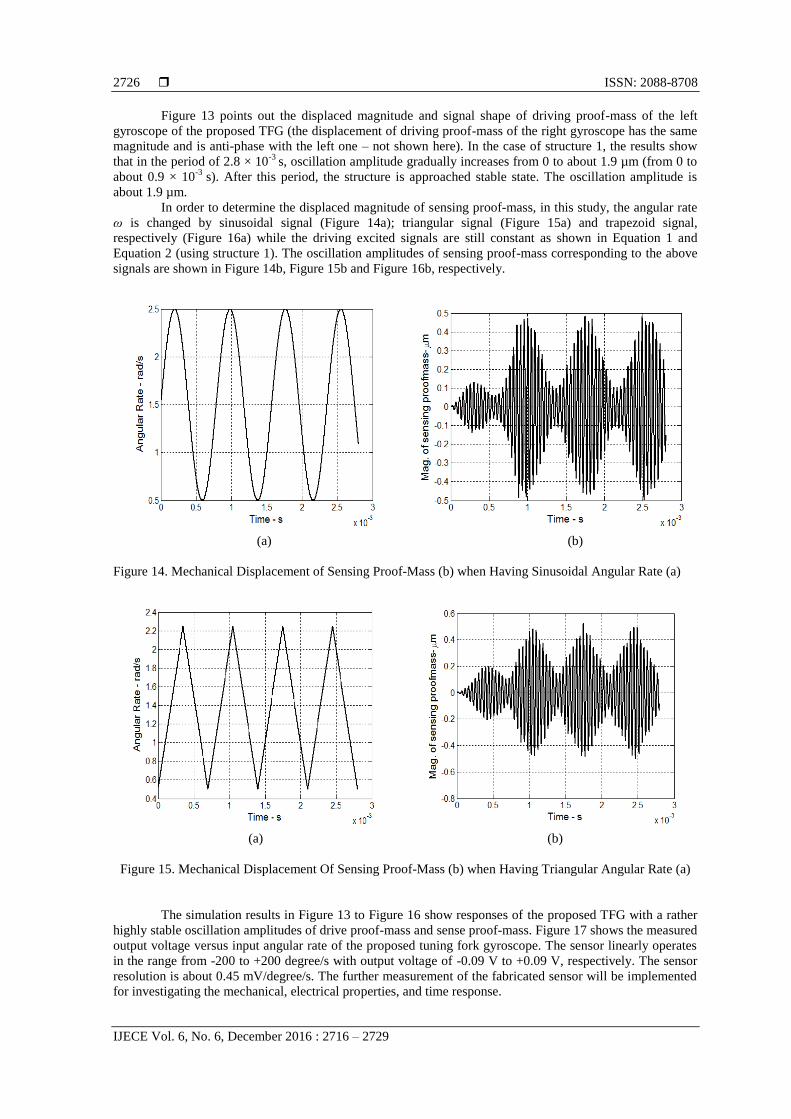
Figure 13 points out the displaced magnitude and signal shape of driving proof-mass of the left
gyroscope of the proposed TFG (the displacement of driving proof-mass of the right gyroscope has the same
magnitude and is anti-phase with the left one – not shown here). In the case of structure 1, the results show
that in the period of 2.8 × 10⁻³
s, oscillation amplitude gradually increases from 0 to about 1.9 µm (from 0 to
about 0.9 × 10⁻³
s). After this period, the structure is approached stable state. The oscillation amplitude is
about 1.9 µm.
In order to determine the displaced magnitude of sensing proof-mass, in this study, the angular rate
ω is changed by sinusoidal signal (Figure 14a); triangular signal (Figure 15a) and trapezoid signal,
respectively (Figure 16a) while the driving excited signals are still constant as shown in Equation 1 and
Equation 2 (using structure 1). The oscillation amplitudes of sensing proof-mass corresponding to the above
signals are shown in Figure 14b, Figure 15b and Figure 16b, respectively.
(a) (b)
Figure 14. Mechanical Displacement of Sensing Proof-Mass (b) when Having Sinusoidal Angular Rate (a)
(a)
(b)
Figure 15. Mechanical Displacement Of Sensing Proof-Mass (b) when Having Triangular Angular Rate (a)
The simulation results in Figure 13 to Figure 16 show responses of the proposed TFG with a rather
highly stable oscillation amplitudes of drive proof-mass and sense proof-mass. Figure 17 shows the measured
output voltage versus input angular rate of the proposed tuning fork gyroscope. The sensor linearly operates
in the range from -200 to +200 degree/s with output voltage of -0.09 V to +0.09 V, respectively. The sensor
resolution is about 0.45 mV/degree/s. The further measurement of the fabricated sensor will be implemented
for investigating the mechanical, electrical properties, and time response.

IJECE ISSN: 2088-8708
Improvement of TFG Drive-mode Oscillation Matched Using a Differential Driving … (Thang Nguyen Van)
2727
(a)
(b)
Figure 16. Mechanical displacement of sensing proof-mass (b) when having trapezoid angular rate (a)
Figure 17. Output Voltage Versus Input Angular Rate
6. CONCLUSION
A novel tuning fork gyroscope with a differential suspension structure between two driving frames
are designed, fabricated and characterized. The driving frame mechanical vibration is well matched when the
electrical driving differential phase is less than 3.5 in structure 1; 2.5 in structure 2; 4 in structure 3. The
differential gained parameters are, therefore, much improved when the common vibration modes between the
two driving frames are ignored. The fabricated tuning fork gyroscope linearly operates in the range from -200
to +200 degree/s with resolution of about 0.45 mV/degree/s.
ACKNOWLEDGEMENTS
This work is partly supported by NAFOSTED project coded 103.99-2014.34. The authors would
like to thank T. Bui Duc of the Faculty of Electronics and Telecommunications for the support on simulation
setup.
REFERENCES [1] IEEE Std 528-2001, IEEE Standard for Inertial Sensor Terminology.
[2] Ayazi, Farrokh, and Khalil Najafi. “Design and fabrication of high-performance polysilicon vibrating ring
gyroscope”, Micro Electro Mechanical Systems, 1998. MEMS 98. Proceedings, the eleventh annual international
workshop on. IEEE, 1998.
[3] Maenaka, Kazusuke, et al, "Design, fabrication and operation of MEMS gimbal gyroscope", Sensors and Actuators
A: Physical, 121.1 (2005): 6-15.
[4] Yazdi, Navid, Farrokh Ayazi, and Khalil Najafi. “Micromachined inertial sensors”, Proceedings of the IEEE 86.8
(1998): 1640-1659.

ISSN: 2088-8708
IJECE Vol. 6, No. 6, December 2016 : 2716 – 2729
2728
[5] Sang Won Yoon, Sangwoo Lee, Khalil Najafi. “Vibration-induced errors in MEMS tuning fork gyroscopes”,
Sensors and Actuators A: Physical, (2012): 32-44.
[6] Weinberg, Marc S., and Anthony Kourepenis. "Error sources in in-plane silicon tuning-fork MEMS gyroscopes",
Journal of Microelectromechanical Systems, 15.3 (2006): 479-491.
[7] Liu, Guangjun, et al, "Effects of environmental temperature on the performance of a micromachined gyroscope",
Microsystem Technologies, 14.2 (2008): 199-204.
[8] Cenk Acar, Andrei Shkel,MEMS Vibratory Gyroscopes: Structural Approaches to Improve Robustness, (2008). p.
8 section, “1.5 Applications of MEMS Gyroscopes”.
[9] Andrei M. Shkel. “Type I and Type II Micromachined Vibratory Gyroscopes”, in Proc. IEEE/ION Position Locat.
Navigat. Symp., San Diego, CA, Apr. 24-27, 2006: 586-593.
[10] D. Piyabongkarn, R. Rajamani, M. Greminger. “The development of a MEMS gyroscope for absolute angle
measurement”, IEEE Transactions on Control Systems Technology, 13 (2005): 185-195.
[11] K. Liu, W. Zhang, W. Chen, K. Li, Fu. Dai, F. Cui, X. Wu, G. Ma, Q. Xiao. “The development of micro-gyroscope
technology”, Journal of Micromechanics and Microengineering, vol 19, no 11 (2009).
[12] M.W. Putty. “A micromachined vibrating ring gyroscope”, Ph.D dissertation, Univ. Michigan, Ann Arbor, MI,
1995.
[13] K. Shcheglov. “DRG-A hight performance MEMS gyro”, in Proc. Joint Precision Azimuth Sensing Symp., Las
Vegas, NV, Aug. 2-4, 2010.
[14] Alexander A. Trusovs, Adam R.Schofield, Andrei M. Shkel. “Micromachined rate gyrocope architecture with ultra-
high quality factor and improved mode ordering”, Sensors and Actuators A: Physical, 165 (2010): 26-34.
[15] Alexander A. Trusovs, Igor P. Prikhodko, Sergei A. Zotov, Andrei M. Shkel. “Low-Dissipation Silicon Tuning
Fork Gyroscopes for Rate and Whole Angle Measurements”, IEEE Sensors Journal, vol. 11, no. 11, November
2011: 2763-2770.
[16] Sheng-Ren Chiu, Chung-Yang Sue, Chih-Hsiou Lin, Yan-Kuin Su. “Dual-axis tuning fork vibratory gyroscope
with anti-phase mode vibration mechanism”, Microsystem Technology, (2014): 2173-2184.
[17] Hung Ngoc Vu, Dzung Viet Dao, Hoang Manh Chu, Thong Quang Trinh, Long Quang Nguyen, and Trinh Chu
Duc.“Design and analysis of a lateral axis tuning fork gyroscope with guided-mechanical coupling”, International
workshop on soft and flexible micro/nano systems technology (2013), Australia.
[18] Simon, Brenton R., Alexander A. Trusov, and Andrei M. Shkel."Anti-phase mode isolation in tuning-fork MEMS
using a lever coupling design", Sensors, 2012 IEEE. IEEE, 2012.
[19] Simon, Brenton R., Alexander A. Trusov, and Andrei M. Shkel."Lever mechanisms for anti-phase mode isolation
in MEMS tuning-fork structures", U.S. Patent No. 9,217,756. 22 Dec. 2015.
[20] Adel. S. Sedra, Kenneth C. Smith. “Microelectronic circuit”, Oxford University Press, 6th edition, 2009.
BIOGRAPHIES OF AUTHORS
Thang Nguyen Van was born in 1979. He received his B.Sc., degree in Electronics and
Telecommunication at the Hanoi University of Transport and Communications, Hanoi, Vietnam,
in 2002 and his M.Sc. degree in Information Engineering from Le Quy Don University, Hanoi,
Vietnam, in 2007. He has been a lecturer of Broadcasting College I under Radio the voice of
Vietnam since 2003. He becomes vice leader of training department of Broadcasting College I
since 2007. Now, he is PhD student of the University of Engineering and Technology (UET),
Vietnam National University Hanoi, Vietnam (VNUH). Until now, He is author and coauthor of
some papers on MEMS based sensors and their application.
Email: [email protected]
Tran-Duc Tan was born in 1980. He received his B.Sc, M.Sc, and PhD. degrees respectively in
2002, 2005, and 2010 at the University of Engineering and Technology (UET), Vietnam
National University – Hanoi, Vietnam (VNUH), where he has been a lecturer since 2006. He
was the recipient of the Vietnam National University, Hanoi, Vietnam Young Scientific Award
in 2008. He is currently an Associate Professor with the Faculty of Electronics and
Telecommunications, University of Engineering and Technology, Vietnam National University,
Hanoi, Vietnam. He is author and coauthor of 30 papers on MEMS based sensors and their
application. His present research interest is in DSP applications.
Email: [email protected]

IJECE ISSN: 2088-8708
Improvement of TFG Drive-mode Oscillation Matched Using a Differential Driving … (Thang Nguyen Van)
2729
Hung Vu Ngoc is an Associate Professor of Materials Science at Hanoi University of Science
and Technology (HUST), Vietnam. He received Bachelor degree in Physics from Kishinev
University, Russia (1979) and PhD in Physics from HUST in 1991. Currently, he is the leader of
MEMS Lab. at International Training Institute for Materials Science (ITIMS). His research
interests range from ferroelectric materials to MEMS technology applied for inertial MEMS
devices.
Email: [email protected]
Trinh Chu Duc received the B.S. degree in physics from Hanoi University of Science, Hanoi,
Vietnam, in 1998, the M.Sc. degree in electrical engineering from Vietnam National University,
Hanoi, in 2002, and the Ph.D. degree from Delft University of Technology, Delft, The
Netherlands, in 2007. His doctoral research concerned piezoresistive sensors, polymeric
actuators, sensing microgrippers for microparticle handling, and microsystems technology. He is
currently an Associate Professor with the Faculty of Electronics and Telecommunications,
University of Engineering and Technology, Vietnam National University, Hanoi, Vietnam. Since
2008, he has been the Vice-Dean of the Faculty of Electronics and Telecommunications. He has
been chair of Microelectromechanical Systems and Microsystems Department, since 2011. He
has authored or coauthored more than 50 journal and conference papers. He was the recipient of
the Vietnam National University, Hanoi, Vietnam Young Scientific Award in 2010, the 20th
anniversary of DIMES, Delft University of Technology, The Netherlands Best Poster Award in
2007 and the 17th European Workshop on Micromechanics Best Poster Award in 2006. He is
guest editor of the Special Issue of “Microelectromechanical systems” Vietnam journal of
Mechanics, in 2012.
Email: [email protected]