improving heat transfer performance of concrete thermal ...2).pdf · international journal of...
TRANSCRIPT

International Journal of Renewable Energy, Vol. 3, No. 2, July 2008
Improving Heat Transfer Performance of Concrete Thermal Energy Storage with Use of Local Material
Watchara Wongpanyoa*, Piyanun Charoensawanb, Wattanapong Rakwichianc,
Pritsathat Seetapand
a*Ph.D. Student, School of Renewable Energy Technology, Naresuan University, Phitsanulok 65000, Thailand bDepartment of Mechanical Engineering, Faculty of Engineering, Naresuan University, Phitsanulok 65000, Thailand cSchool of Renewable Energy Technology, Naresuan University, Phitsanulok 65000, Thailand dDepartment of Civil Engineering, Faculty of Engineering, Naresuan University, Phitsanulok 65000, Thailand
Tel: +66-5526-1067, Fax: +66-5526-1067, E-mail: [email protected]
ABSTRACT
This paper presents the temperature distribution of concrete storage systems, in which the oil inlet temperature for charging was 250 °C. This study was done based on the climatic conditions of Phitsanulok province, Thailan for concrete storage for a parabolic trough collector in the Energy Park of School of Renewable Energy Technology (SERT), the Naresuan University. The local materials volumetric ratios are water (1): cement (1): sand (1.5): rock (3) were suitable for use in a concrete storage system. The calculations of heat transfers could predict the temperature distribution and heat capacity within the concrete media and this system of analysis simulation helped to improve the efficiency of the storage system significantly. Keywords: Concrete Thermal energy storage, Temperature distribution, Heat transfer Performance 1. INTRODUCTION
Concentrating solar power (CSP) technologies use solar radiation to achieve high temperatures and to generate steam or air with a high energy density, which can then be used for electricity generation and other purposes. Thus solar thermal power plants are very similar to conventional power cycles; the only difference is their energy source.
Parabolic trough solar thermal electric power plant technology represents one of the major renewable energy success stories of the last two decades. Parabolic troughs are one of the lowest cost solar electric power options available today and have significant potential for further cost reduction.
Parabolic trough power plants use concentrated sunlight, in place of fossil fuels, to provide the thermal energy required to drive a conventional power plant. These plants use a large field of parabolic trough collectors which track the sun during the day and concentrate the solar radiation on a receiver tube located at the focus of the parabolic shaped mirrors. A heat transfer fluid passes through the receiver and is heated to temperatures required to generate steam and drive a conventional Rankine cycle steam power plant.
However, the use of solar energy presently poses technical problems, primarily because of inefficient collection and storage. Therefore, developing efficient and inexpensive energy storage devices is as important an endeavor as developing new sources of energy.
Solar heat can be stored during the day in concrete, ceramics or phase change media. At night, it can be extracted from the storage to run a power block. Fossil and renewable fuels like oil, gas and organic waste can be used for co-firing the plant, providing power by demand, as a base or peak load (Figure 1).

International Journal of Renewable Energy, Vol. 3, No. 2, July 2008
16
Solar Heat Fuel
Electricity
Heat
Fig. 1 Solar thermal power plant and thermal energy storage [1].
Developing efficient and inexpensive energy storage devices is as important a field as developing new sources of energy. Energy storage can reduce the time or rate mismatch between energy supply and energy demand, thereby playing a vital role in energy conservation. It improves the performance of energy systems by smoothening the output and thus increasing reliability. For example, storage would improve the performance of a power generating plant by load leveling. The higher efficiency would help energy conservation and improve cost effectiveness. Some renewable energy resources can provide only an intermittent energy supply, e.g. solar energy. Consequently in most solar energy systems a back up or auxiliary energy source becomes essential. The provision of solar thermal energy storage can reduce auxiliary energy consumption to a great extent and increase the so called solar load fraction substantially, thus conserving valuable fossil fuel reserves; coal, oil, and natural gas.
Nature has been storing vast amounts of solar energy in the form of biomass and fossil fuels. However, this process takes a very long time. If the present rate of industrialization is to be maintained, and the amenities from man made systems are to continue to be available, then storage of energy is essential. The storage of energy in suitable forms, which can conveniently be converted into the required form, is a present day challenge to the technologists.
It is clear that if solar energy is to become an important energy source, efficient, economical and reliable solar thermal energy storage devices and methods will have to be developed [2].
2. DEVELOPMENT OF STORAGE MEDIA MATERIAL
Thermal energy may be stored as sensible heat or latent heat. Sensible heat storage systems use the heat capacity and the change in temperature of the material during the process of charging and discharging. The temperature of the storage material rises when energy is absorbed and drops when energy is withdrawn. Sensible heat, Q is stored in material of mass (m) and specific heat (cp) by raising the temperature of the storage material from T1 to T2 and is expressed by Eq.1
dTcVdTmcQT
Tp
T
Tp ∫∫ ==
2
1
2
1
ρ (1)
When ρ and V are density and volume of the storage materials, respectively, for moderate temperature changes, such as for solar space and water heating system, the density and specific heat may be considered constants. Therefore, Q=ρVcpΔT. The most common sensible heat storage materials are water, organic oils, rocks, ceramics, and molten salt [3]. From this equation the higher the specific heat and density of the material, the more energy could be stored in a given volume of material. However, there are several other parameters which also affect the performance of the system: the temperature of operation, thermal conductivity, thermal diffusivity, vapour pressure compatibility
Concentrating Solar Collector Field
Power Block
Thermal Energy Storage (Optional)

International Journal of Renewable Energy, Vol. 3, No. 2, July 2008
17
between the storage material and the container, stability of the material at the highest temperature of cyclic operation, and the cost of the system [4].
2.1 Selection of a sensible heat storage media
The difficulties of the high vapour pressure of water and the limitations of other liquids can
be avoided by storing thermal energy heat in solids. For parabolic trough power plants using synthetic oil as the heat transfer medium, the application of solid media sensible heat storage is an attractive option with regards to investment and maintenance costs. Cost effective systems demand the utilization of inexpensive storage materials, which usually exhibit a low thermal conductivity. Essential for the successful development of a storage system is a sufficient heat transfer between the synthetic oil and the storage materials.
2.2 Advantages of sensible heat storage in solids For high and medium temperature applications, sensible heat storage in solid media can be
an effective method. Solids have an energy density value (kg/m3) equivalent to many organic liquids, but slightly
less than pressurized water. Hence from an energy density point of view these are of interest, though their thermal conductivity is small, which involves a large surface-to-volume ratio for dynamic heat transfer.
2.3 The technical requirements for sensible heat storage in solids The concept of using a concrete storage matrix as economical, large scale bulk thermal
storage for a parabolic trough is entirely new and has the following advantages [5]: • High specific heat capacity • Low cost • Easy on site processing • Adapted technology that can be implemented in sunbelt countries • Aggregates for concrete available everywhere cheaply
In an overall view high temperature concrete seems to be the most favorable material. Reasons are the lower costs and easier handing of the pre-mixed material [6].
2.4 Reinforce concrete
Concrete is a nonhomogeneous manufactured stone composed of graded, granular inert
materials which are held together by the action of cementitious materials and water. The inert materials usually consist of gravel or large particles of crushed stone, and sand or pulverized stone. The inert materials are called aggregates. The large particles are called coarse aggregates and the small particles are called fine aggregates.
Concrete behaves very well when subjected to compressive forces, but ruptures suddenly when small tension forces are applied. Therefore in order to utilize this material effectively, steel reinforcement is placed in the areas subjected to tension. Steel is also often used to assist the concrete in resisting compression forces. Concrete is always assumed to be incapable of resisting tension, even though it actually can resist a small amount of tension [7].
Research activities at DLR-German Aerospace Center-Institute of Technical Thermodynamics are aiming at the development and validation of new innovative concepts and approachs for energy storage for CSP technologies. As an innovative storage material a castable ceramic, which is principally composed of a binder (including Al2O3) aggregates (iron oxide) and various other materials, has been developed. The binder is setting chemically under ambient conditions and forms a solid, stable matrix, which encloses the aggregates. With this material a density of 3,500 kg/m³ is reached and the thermal conductivity is slightly higher than that of concrete. Alternatively, high temperature concrete has been developed with a high density of 2,750 kg/m³.

International Journal of Renewable Energy, Vol. 3, No. 2, July 2008
18
Eventually, the final material costs will determine if the benefits of the better thermo-physical properties of the castable ceramic can overcome the higher costs (Table 2).
From DLR research the thermal energy storage system in CSP technology is very important. Most TES consists of latent heat or solid heat. Latent heat storage uses PCM technology to store energy. The limit of PCM is that it doest not support high temperatures. Sensible heat storage is very attractive. For lab research at the PSA, high temperature storage concrete used various aggregates, composition, water/cement ratios and reinforcement elements (like steel needles) to storage units. But the cost of the storage is very high and not appropriate in Thailand.
For improving the thermal energy storage performance for a Parabolic Trough in Thailand will used the local materials because the costs are lower and there is lots of room for storage volume.
3. TESTING PROPERTIES OF INTERESTING SOLID MATERIALS
3.1 Materials Testing
Solid storage material is characterized by thermal conductivity, specific heat capacity and density. Interesting solid materials used in the experiment were reinforced concrete aggregates which are composed of local aggregate materials in Thailand i.e. water, cement, sand and rock (Table 1).
The water-cement ratios (W/C) are the most important single factors involved in mixing concrete. Using average materials, the strength of the concrete and all of the other desirable properties of concrete are directly related to the water-cement ratio. In this study fix the ratio of water depend on the cement ratio because study the other aggregates ratio [8]. Table 1 Sample of testes concrete aggregates.
Sample of concrete aggregates Volumetric ratio (water: cement: sand: rock) Sample 1 1:1:1.5:3 Sample 2 1:1:2:4 Sample 3 1:1:2.5:4 Sample 4 1:1:3:5

International Journal of Renewable Energy, Vol. 3, No. 2, July 2008
19
Fig. 2 Configuration of tested sample of concrete mix materials
with the size of 30 cm.*30 cm*2.54 cm. (a) Thermal conductivity test instrument (b) Specific heat capacity test instrument
Fig. 3 Test instrument of thermophysical properties of concrete mix materials.
Figure 3 (a) shows the electricity heater plate to brace concrete block (30 cm.*30 cm*2.54 cm.), collect the high and low temperatures and then use the data to calculate the thermal conductivity. Figure 3 (b) the instrument to find the Specific heat capacity of concrete mix materials. Sample test at Department of Science, Ministry of Science and Technology.

International Journal of Renewable Energy, Vol. 3, No. 2, July 2008
20
3.2 Properties of Materials
The materials property was analyzed and the results are shown in Table 2. Table 2 Thermophysical properties of tested concrete mix materials comparing with that of storage materials developed at DLR [6].
Sample 1 Sample 2 Sample 3 Sample 4 High Temp. Concrete[6]
Castable Ceramics[6]
Density (kg/m3) 1798.7 1806.0 1787.9 1846.0 2750 3500 Specific heat capacity (J/kgK)
1015 928.3 896.9 804.9 916 866
ρ*Cp(kJ/ m3K) 1825.68 1676.51 1603.57 1485.85 2519 3031 Thermal conductivity (W/mK)
0.40 0.33 0.32 0.31 1.0 1.35
Costs* (Baht/m3) 1075 950 905 832 6850 13500
The results show that the thermal conductivity, specific heat capacity and density are closely equal to the DLR laboratory. The thermal conductivity is lower but the costs of the DLR laboratory are higher.
The method to solve the problems resulting from the low thermal conductivity is by reducing the average distance between the hot oil tubes within the storage material. 4. MATHEMATICAL MODELLING OF CONCRETE STORAGE SYSTEM Calculation of heat transference, by using the experimental results about concrete materials properties in Table 2 was used for system analysis simulation to understand the interaction of the storage unit with the other components. The results of this system analysis simulation helped to significantly improve the efficiency of storage system.
Figure 4 shows a cross-section of a concrete storage block in which a number of hot oil tubes are embedded.
Fig. 4 Cross-section of a concrete storage block.
The storage system is composed 36 tubes of high-temperature steel. They are distributed in a square arrangement of 6 by 6 tubes. The diameter of the flow channel is 0.02 m, the distance between two parallel channels is 0.08 m. Collector and distributors have been designed for optimal uniform flow distribution in all tubes.
International Journal of Renewable Energy, Vol. 3, No. 2, July 2008
21
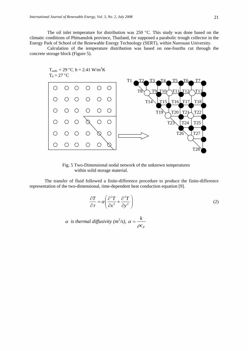
The oil inlet temperature for distribution was 250 °C. This study was done based on the climatic conditions of Phitsanulok province, Thailand, for supposed a parabolic trough collector in the Energy Park of School of the Renewable Energy Technology (SERT), within Naresuan University.
Calculation of the temperature distribution was based on one-fourths cut through the concrete storage block (Figure 5).
Tamb. = 29 °C, h = 2.41 W/m2K T0 = 27 °C
T1 T2 T3 T4 T5 T6 T7 T8 T9 T10 T11 T12 T13 T14 T15 T16 T17 T18 T19 T20 T21 T22 T23 T24 T25
T26 T27
T28
Fig. 5 Two-Dimensional nodal network of the unknown temperatures within solid storage material.
The transfer of fluid followed a finite-difference procedure to produce the finite-difference
representation of the two-dimensional, time-dependent heat conduction equation [9].
⎟⎟⎠
⎞⎜⎜⎝
⎛∂∂
+∂∂
=∂∂
2
2
2
2
yT
xTT α
τ (2)
α is thermal diffusivity (m2/s), Pc
kρ
α =

International Journal of Renewable Energy, Vol. 3, No. 2, July 2008
22
Table 3 Summary of transient, two-dimensional finite-difference equation (Δx=Δy) [10]. Explicit Method Configuration
Finite-Difference Equation Stability Criterion
1. Interior node:
pnm
pnm
pnm
pnm
pnm
pnm
TFoT
TTTFoT
,1,
1,,1,11
,
)41()
(
−++
++=
−
+−++
41
≤Fo
2. Node at interior corner with convection
pnm
pnm
pnm
pnm
pnm
pnm
TBiFoFo
BiTT
TTTFoT
,
1,
1,,1,11
,
)3141(
)2
22(32
−−+
++
++=
∞−
+−++
43)3( ≤+ BiFo
3. Node at plane surface with convection*
pnm
pnm
pnm
pnm
pnm
TBiFoFoBiT
TTTFoT
,
1,1,,11
,
)241()2
2(
−−++
++=
∞
−+−+
21)2( ≤+ BiFo
4. Node at exterior corner with convection
pnm
pnm
pnm
pnm
TBiFoFo
BiTTTFoT
,
1,,11
,
)441(
)2(2
−−+
++= ∞−−+
41)1( ≤+ BiFo
* To obtain the finite-difference equation and/or stability criterion for an adiabatic surface (or surface of symmetry); simply set Bi equal to zero.
From figure 5 have 28 equations to predict the temperature distribution of concrete storage which following: The interior nodes are T9, T11, T15, T16, T17, T20, and T24.
The insulated boundary nodes are T2, T3, T4, T5, and T6. The convection boundary nodes are T13, T18, T22, T25, and T27. Other condition nodes are T1, T28, T14, T23, and T7. The oil inlet nodes are T8, T10, T12, T19, T21, T26 and which are considered to be
constant at 250 °C.

International Journal of Renewable Energy, Vol. 3, No. 2, July 2008
23
5. RESULTS AND DISCUSSION
5.1 Temperature Distribution
Figure 6 show the prediction of the mathematical model of the temperature distribution of concrete storage by using the properties (sample 1, Table 2) because sample 1 had a thermal conductivity, specific heat capacity and density higher than the other samples. Sample was then compared with the properties of storage materials developed at DLR (high temperature concrete, Table 2).
Fig. 6a The prediction temperature distribution of the interior node Fig. 6b The prediction temperature distribution of the insulated boundary node
Fig. 6c The prediction temperature distribution of the convection boundary node Fig. 6d The prediction temperature distribution of another condition node (T1)
Fig. 6e The prediction temperature distribution of another condition node (T14) Fig. 6f The prediction temperature distribution of the another condition node (T23)
Fig. 6g The prediction temperature distribution of another condition node (T7) Fig. 6h The prediction temperature distribution of another condition node (T28)
Fig. 6 The temperature distribution of sample 1 compared with high temperature concrete.
The interior node
0
50
100
150
200
250
300
0 500 1000 1500 2000 2500 3000 3500 4000
Time(sec)
Temp(Degree celsius)
T9(DLR)T9(LAB)
The convection boundary node
0
50
100
150
200
250
300
0 500 1000 1500 2000 2500 3000 3500 4000
Time(sec)
Temp(degree celsius)
T13(DLR)T13(LAB)
The another condition node(T1)
0
50
100
150
200
250
300
0 500 1000 1500 2000 2500 3000 3500 4000
Time(sec)
Temp(Degree celsius)
T1(DLR)T1(LAB)
The another condition node(T14)
0
50
100
150
200
250
300
0 500 1000 1500 2000 2500 3000 3500 4000
Time(sec)
Temp(Degree celsius)
T14(DLR)T14(LAB)
The another condition node(T23)
0
50
100
150
200
250
300
0 500 1000 1500 2000 2500 3000 3500 4000
Time(sec)
Temp(Degree ce lsius)
T23(DLR)T23(LAB)
The another condition node(T7)
0
50
100
150
200
250
300
0 500 1000 1500 2000 2500 3000 3500 4000
Time(sec)
Temp(Degree celsius)
T7(DLR)T7(LAB)
The another condition node(T28)
0
50
100
150
200
250
300
0 500 1000 1500 2000 2500 3000 3500 4000
Time(sec)
Temp(Degree celsius)
T28(DLR)T28(LAB)
The insulated boundary node
0
50
100
150
200
250
300
0 500 1000 1500 2000 2500 3000 3500 4000
Time(sec)
Temp(Degree ce lsius)
T2(DLR)T2(LAB)

International Journal of Renewable Energy, Vol. 3, No. 2, July 2008
24
In Figure 6a (The interior node) high temperature concrete achieved 250 °C in 1200 seconds whereas sample 1 achieved 250 °C in 1400 seconds. Both remained constant after 1500 seconds.
In Figure 6b (The insulated boundary node) high temperature concrete achieved 250 °C in 1100 seconds whereas sample 1 achieved 250 °C in 1300 seconds. Both remained constant after 1400 seconds.
In Figure 6c (The convection boundary node) high temperature concrete achieved 200 °C in 1000 seconds whereas sample 1 achieved 170 °C in 1100 seconds. Both remained constant after 1200 seconds.
In Figure 6d (Another condition nodes are T1) high temperature concrete achieved 250 °C in 1200 seconds whereas sample 1 achieved 250 °C in 1400 seconds. Both remained constant after 1500 seconds.
In Figure 6e (Another condition nodes are T14) high temperature concrete achieved 250 °C in 1200 seconds whereas sample 1 achieved 250 °C in 1400 seconds. Both remained constant after 1500 seconds.
In Figure 6f (Another condition nodes are T23) high temperature concrete achieved 240 °C in 1300 seconds whereas sample 1 achieved 240 °C in 1500 seconds. Both remained constant after 1600 seconds.
In Figure 6g (Another condition nodes are T7) high temperature concrete achieved 200 °C in 1000 seconds whereas sample 1 achieved 160 °C in 1100 seconds. Both remained constant after 1500 seconds.
In Figure 6h (Another condition nodes are T28) high temperature concrete achieved 170 °C in 1000 seconds whereas sample 1 achieved 110 °C in 1200 seconds. Both remained constant after 1300 seconds.
Figure 6 represents the predicted the temperature distribution in concrete storage by use of the properties of sample 1 and the DLR when the oil inlet temperature for charging was 250 °C.
The sample 1 and high temperature concrete went from concrete temperature remained constant for 3600 seconds and end of charging.
The prediction temperature distribution results of both laboratories were close but in some nodes (T7, T13 and T28) the results of sample 1 are lower than the DLR, because the thermal conductivity was lower. The method to solve this problem is reducing the average distance of the heat tubes within the storage media. Reducing the average distance for heat transport in the storage materials means increasing the amount of tube and it will the dynamic in the storage system.
5.2 Heat capacity
The concrete storage systems can be finding the heat capacity from Eq.1 by use the materials properties have been analyzed at laboratory (Table 2). The results are shown in table 3. Table 4 Heat capacity of concrete mix materials storage by using local materials compare with material properties of high temperature concrete developed at DLR.
Solid media Q(MJ) Sample 1 1719.56 Sample 2 1682.29 Sample 3 1676.25 Sample 4 1670.05
High temperature concrete 2588.54 The results show the heat capacity of the 4 samples using local materials aggregates and high temperature concrete. The heat capacity of sample 1 was higher than other samples but lower than high temperature concrete. To solve this problem we made 2 blocks of sample 1 with a higher heat capacity higher and the costs were still lower than high temperature concrete (Table2).

International Journal of Renewable Energy, Vol. 3, No. 2, July 2008
25
6. CONCLUSIONS From all results, it can be concluded that:
6.1 Effectiveness of concrete storage system depends on the specific heat capacity, from table 2 specific heat capacity of sample 1 is higher than another sample and higher than materials properties of storage materials developed at DLR.
6.2 The thermal energy storage system for a parabolic trough by using local materials in Thailand for sample 1 volumetric ratio are water (1): cement (1): sand (1.5): rock (3) suitable for use in concrete storage system because the thermal conductivity and specific heat capacity was higher than other samples.
6.3 The calculations of heat transfers could predict the temperature distribution and heat capacity within the concrete media and this system analysis simulation help to improve the efficiency of the storage system significantly.
6.4 The prediction temperature distribution of concrete storage by using the properties of the study (sample1) and the DLR developed (high temperature concrete) are close but the costs of the local materials are lower.
6.5 The node of sample1 which lower than high temperature concrete, the method to solve this problems resulting is reducing the average distance of the heat tubes within the storage media. Acknowledgement The author would like to express sincerely to Supervisor, Asst.Prof.Dr. Piyanun Charoensawan, Co- Supervisor, Assoc.Prof.Dr.Wattanapong Rakwichian and Dr. Pritsathat Seetapan, for guidance, suggestion and encouragement throughout this study. I would like to thank you Naresuan University Phayao and Energy and Planning Office (EPPO), Thailand for supposed scholarship. Special thanks are due to staff of School of Renewable Energy Technology (SERT), Naresuan University. Nomenclature Q: Heat capacity (J) m: Mass of the storage material (kg) V: Volume of the storage material (m3) cp: Specific heat capacity (J/kgK) ρ: Density of the storage material (kg/m3) k: Thermal conductivity (W/mK) Tamb: Ambient Temperature (°C) TC: Concrete Temperature (°C) h: Convection heat transfer coefficient (W/m2) α: Thermal diffusivity (m2/s) References [1] Franz.Trieb. Solar Thermal Power Plants: Solar Collector instead of Fuel. DLR-Institute of
Technical Thermodynamics, Stuttgart, Germany. [2] H P Garg & J Prakash. (1997) Solar Energy Fundamentals and Applications. New Delhi: Tata
McGraw-Hill Publishing. 351 [3] H. Yuncu, E. Paykoc, Y.Yener.(1987). Solar Energy Utilization. Martinus Nijhoff Publishers:
Netherlands, 454-455 [4] D. Yogi Goswami, Frank Kreith, Jan F. Kreider. Principles of Solar Engineering. 2nd ed.
George H.Buchanan Co., Philadelphia, PA, 173-176 [5] B S Magal. Solar Power Engineering. New Delhi: Tata McGraw-Hill Publishing. 208-211

International Journal of Renewable Energy, Vol. 3, No. 2, July 2008
26
[6] Doerte Laing, Wolf-Dieter Steinmann, Rainer Tamme, Christoph Richter. Solid media thermal storage for parabolic trough power plants. DLR - German Aerospace Centre – Institute of Technical Thermodynamics. ScienceDirect Solar Energy 80 (2006) 1283-1289
[7] Schaum’s Outline of Theory and Problems of REINFORCED CONCRETE DESIGN, 2nd&3rd, Singapore: McGraw-Hill Co.
[8] Joseph J. Waddell, P.E., Joseph A. Dobrowolski, P.E., 3rd ed., (1993), Concrete construction handbook. McGraw-Hill. 640-641
[9] M.Necati Ozisik. Heat Transfer A Basic Approach. McGraw-Hill International Editions. 191- 192
[10] Frank P.Incropera, David P.Dewitt. Introduction to heat transfer. Fourth edition. John Wiley&Sons.Inc. The United States of America. 280-284