imrt for h/n cancer · example for npc –gtv • gross tumor on mri and pe –ctv • gtv + margin...
TRANSCRIPT

IMRT for H/N CancerIMRT for H/N Cancer
Todd PawlickiDepartment of Radiation OncologyStanford University School of Medicine

Outline1. Why IMRT for HN cancer
2. Immbolization
3. Tissue segmentation
4. Treatment planning
5. Plan evaluation
6. Summary

Why IMRT for HN CancerMiles et al. Radiother Oncol. 2005;77(3):421-426.
• Complex anatomical region– Normal tissues and targets in close proximity
• Inadequate 3D planning techniques– No way to deliver concave dose distributions
• Absence of organ motion
Kuppersmith et al. Ear Nose Throat J. 1999;78(4):238,241-246.
Pacholke et al. Am J Clin Oncol. 2005;28(4):351-358.

Complex Anatomical RegionMartinez-Monge et al. Radiology. 1999;211:815-828.
• Optic nerves, chiasm, eyes, lenses • Spinal cord, brainstem • Parotid glands• Oral cavity• Temporal lobes• Mandible, TMJ• Larynx, …

Inadequate Conventional PlanningPacholke et al. Am J Clin Oncol. 2005;28(4):415-423.
Opposed Laterals Off-cord electron fields
Questionable dosimetry at photon-electron beam matchline

Indications and Contra-Indications
• Cooperative patients– No claustrophobia, resting tremors, etc.
• Reduce normal tissue complications– Conformal avoidance
• To escalate dose– Improve local-regional control
• Avoid unwanted field junctions

Absence of Organ Motion
• Little or no intra-fraction organ motion
• Inter-fraction setup uncertainty can be controlled with usual intervention
Outline
1. IMRT for HN cancer
2. Immbolization
3. Tissue segmentation
4. Treatment planning
5. Plan evaluation
6. Treatment efficacy
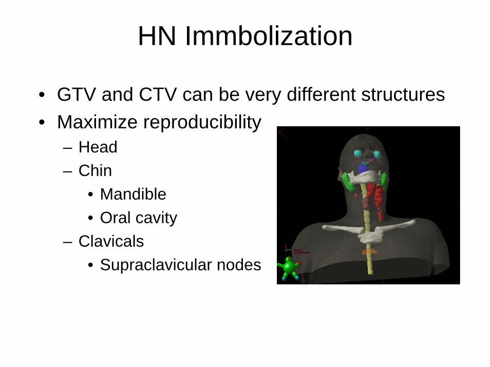
HN Immbolization
• GTV and CTV can be very different structures• Maximize reproducibility
– Head– Chin
• Mandible• Oral cavity
– Clavicals• Supraclavicular nodes

Immbolization Options(“Active”)

Immbolization Options(“Passive”)
• Masking system with Accuformcustom neck mold
• Patient comfort and immbolization go hand-in-hand

Immbolization Options(“Passive”)
• shoulder constraints

Expected Reproducibility
• Locate isocenter in head or upper neck• Generally, setup error within 3 mm can be
achieved– 1 – 2 mm in the head and neck– 2 – 3 mm in the shoulder region
• However, some variability can be expected– Treatment plans should account for those effects
Tsai et al. Int J Radiat Oncol Biol Phys. 1999;43(2):455-467.
Hong et al. Int J Radiat Oncol Biol Phys. 1005;61(3):779-788.

Outline
1. IMRT for HN cancer
2. Immbolization
3. Tissue segmentation
4. Treatment planning
5. Plan evaluation
6. Summary

Aspects of Imaging
– Target volumes
– Normal tissues
– Image fusion

Target Volume DelineationICRU 50
Example for NPC– GTV
• Gross tumor on MRI and PE– CTV
• GTV + margin including, nasopharynx, retropharyngeal nodes, clivus, skull base, inferior sphenoid sinus, pterygoidfossae, parapharyngeal space, posterior nasal cavity and maxillary sinuses
– PTV• CTV + 3-5 mm

Target Volume DelineationICRU 62
• ITV (internal target volume)– ITV = CTV + IM– IM (internal margin)
• Due to physiologic variations– SM (setup margin)
• Due to technical factors
• PRV (planning organ at risk volume)– Margin added to OARs
CTVIM
ITV
SMPTV
OAR
PRV

Consistent with ICRU Definitions• GTV-T, GTV-N• CTV-T, CTV-N1, CTV-N2, etc.

CT Anatomy – Head
chiasm
brainstem
optic nerves

CT Anatomy – Head
brainstem
temporal lobes

CT Anatomy – Headmandible
brainstem
parotids

CT Anatomy – Head/Neck
Location of inferior brainstem and superior spinal cord

CT Anatomy – Neck

CT Anatomy – NeckCranial
Caudal
Region of brachial plexus nerve
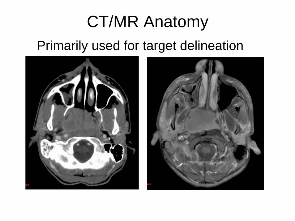
CT/MR AnatomyPrimarily used for target delineation

CT Anatomy – Neck
Spinal canal
vs
Spinal cord
Use PRV (ICRU-62) for margin around spinal cord

PET Images• Malignant cells divide rapidly and metabolize
glucose at a higher rate than that of healthy cells
• Attach a positron emitter (fluorine-18) to a glucose analogue
• FDG PET studies depict glucose utilization of the glucose analogue fluorodeoxyglucose– Tumor metabolism
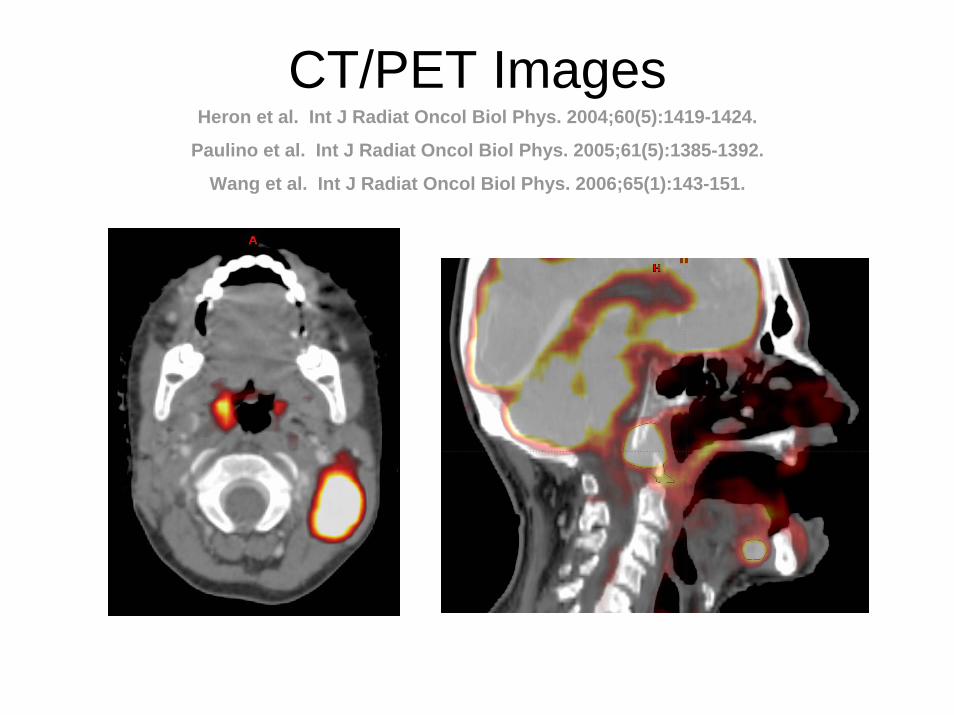
CT/PET ImagesHeron et al. Int J Radiat Oncol Biol Phys. 2004;60(5):1419-1424.
Paulino et al. Int J Radiat Oncol Biol Phys. 2005;61(5):1385-1392.
Wang et al. Int J Radiat Oncol Biol Phys. 2006;65(1):143-151.

Multi-modality Image Fusion• Participate in process before imaging
takes place– Ensure same position– Understand setup/imaging limitations
• Talk with physician about site of interest– Location, pre- or post-op, etc.
• Communicate uncertainty of manually fused images

Outline
1. IMRT for HN cancer
2. Immbolization
3. Tissue segmentation
4. Treatment planning
5. Plan evaluation
6. Summary
Before Planning Begins• Is IMRT appropriate for this case?
• Where is the target?
• What are target doses & acceptable normal tissue doses?– What can be compromised?
• What is the plan?– Simultaneous integrated boost versus
sequential cone down plans?

IMRT Planning• Same primary target as with 3DCRT• Regional therapy requires specific
identification of nodes• Simultaneous boost
– Lower regional dose per fraction (e.g. GTV to 66Gy and nodes to 54Gy both in 30 fractions)
• Sequential boost– Same dose per fraction for GTV and nodes– Requires two plans

Physician Communication(managing expectations)
• Isodose lines are not as smooth as 3DCRT– Increases dose heterogeneity, which may
affect toxicity, tumor control probability• You can not specify an isodose line to move
by millimeters– IMRT planning is not like changing a
block edge• Hot/cold spot will fall within the target(s)

Issues with IMRT Treatments
• Time consuming planning process and quality assurance procedures
• Many factors in plan evaluation of uncertain significance
• Exchanges exposure of larger volumes of normal tissue to low doses for smaller volumes exposed to high doses

Tissue Inhomogeneity Corrections
• AAPM Report No. 85: Tissue InhomogeneityCorrections for Megavoltage Photon Beams
• 4 – 10% error in relative e- density results in ~2% error in dose
• CT Streak artifacts can be locally significant– Do not normalize a plan to a point in this region– Little effect on DVH of large structures

Dose Calculation Accuracy• Two types of dose calculation errors
– Systematic error (same as in 3DCRT)– Convergence error (related to optimization)
• Convergence error– The optimization algorithm converges to a solution
based on inaccurate beamlets
• Approximate errors at tumor for HN cases– Systematic: 0 – 3 %Dmax– Convergence: 3 – 6 %Dmax

Know Published Dose Limits(understand what your physician will accept)
Tissue Maximal Dose* (Gy) Mean Dose (Gy) Reference Brain 60 - Emami et al 1991
Brainstem 54 - Emami et al 1991 Optic chiasm/nerves 54 - Emami et al 1991
Retina 45 - Emami et al 1991 Lens 12 - Emami et al 1991
Parotid 70 26 Eisbruch et al 2003 Larynx 70 ≤ 25 – 30 Stanford
Mandible 65 ≤ 35 – 45 Stanford Spinal cord 45 - Emami et al 1991
*We recommend lowering these dose limits by 10% when concurrent chemotherapy is used.

IMRT Planning Parameters
• Dose/volume constraints• Number of beams• Beam orientation / Table angles• Tuning structures• Collimator angle• Isocenter placement• Beamlet size / Intensity levels• Direct modification of intensity maps

Number of Beams
• More beams = Better plan ?
• Generally Yes– But improvement can be marginal over
7 beams– Degree of improvement depends on
tumor shape and proximity to critical structures

3 – Field
7 – Field
5 – Field
All plans have the same optimization parameters
Beam Orientation
• Coplanar vs Non-coplanar– Ease of setup– Ease of planning– Speed of treatment
• Equi-spaced vs Selected angles– Entrance through table/immobilization device

Beam Orientation

Collimator Orientation

Collimator Orientation
Collimator angle with leaf travel direction perpendicular to the brainstem/spinal cord
180o collimator angle

Tuning Structure
• A structure added just for the purpose of treatment planning
• Provides additional control over the dose distribution in IMRT plans
• Reduce normal tissue dose
• Reduce/Increase target dose

Tuning Structure

Tuning Structure
An added structure to be used in optimization

Tuning Structure

Tuning Structure
GTV66 and CTV60
T0N3M0 SCC R Neck Unknown Primary s/p RMRND.
GTV66 and CTV60
CTV54
CTV54, but will accept a lower dose (ie 52)

Isocenter Placement
Issues• Sometimes a better plan be achieved by
selective isocenter placement– Center of GTV vs center of all targets
• Dosimetry and/or QA• Patient setup
– Isocenter in region of reliable bony anatomy

Isocenter Placement
Isocenter in geometric center of targets
Isocenter in geometric center of GTV

Isocenter Placement
Choose a reliable anatomical reference point

Prostate case #2 (discrete annealing) - CTV
0
20
40
60
80
100
120
65 70 75 80 85dose [Gy]
volu
me
[%]
2%5%10%20%33%50%
Number of Intensity Levels
Lehmann et al. 2000
502010532

Direct Modification of Intensity Map
An option provided by some planning systems

Direct Modification of Intensity Map

Direct Modification of Intensity Map
Erase intensity over the RT Eye in all fields

HN IMRT with Supraclav Nodes
• Treating nodes in IMRT– Eliminates junction issues– Requires extra care to immobolize shoulders– Do not treat the supraclav nodes through the shoulders
• Treating nodes with AP field– Requires a method to match the IMRT fields– Not advised for node positive cases– If possible, include SCV field in IMRT optimization

HN IMRT with Supraclav Nodes
No need to contour nodal volumes for conventional technique
Matched below GTV

Matching IMRT to AP SCV (1)
50% isodose line on IMRT plan – SCV match line is 2-3 mm inferior
IMRT plan restricted to co-planar beams with standard collimator angle (Varian Col ∠ 180)

IMRT/AP SCV Single Isocenter
AP SCV Field AP IMRT Field
Li et al. Matching IMRT fields with static photon field in the treatment of head-and-neck cancer. Med Dosim. 2005;30(3):135-138.

Matching IMRT to AP SCV (2)
Include SCV field in optimization of IMRT plan.

Matching IMRT to AP SCV (2)Sethi et al. Matching tomographic IMRT fields with static photon fields. Med Phys. 2001;28(12):2459-2465.
Duan et al. A dynamic supraclavicular field-matching technique for head-and-neck cancer patients treated with IMRT. Int J Radiat Oncol Biol Phys. 2004;60(3):959-972.
Flexibility to control hot, cold or feathered match-line.

Final Comments on Treatment Planning
• Beam energy– 4 – 6MV is usually sufficient– Sometimes a higher energy PA beam can
help to cover supraclav nodes and reduce posterior hot spots
• Skin dose– Immbolization masking systems can act as a
bolus to produce a severe skin reaction

Outline
1. IMRT for HN cancer
2. Immbolization
3. Tissue segmentation
4. Treatment planning
5. Plan evaluation
6. Summary

Plan Evaluation
• When the planning is “finished”– The worst thing you can do
• What are achievable doses– An average of 10 HN cases
• Final comments

When The Plan is Finished• Do not allow the physician to review the plan alone
• Talk through the plan with the physician– What is good and bad about this plan?– Why did you use those beam angles?– Why underdose parts of the target?– Why can’t you spare more normal tissue?
• You have to intrude on the physician’s decision making process as much as possible

About Plan Evaluation
• A plan may produce a maximal point dose that exceeds the so-called tolerance dose for a critical structure
• It is important to review the DVH to determine how much of the critical structure volume receives doses exceeding the specified limit– In many cases, it only correlates to a few voxels
and may be acceptable

About Plan Evaluation• Hot and cold spots must be identified
using the isodose curves on a slice-by-slice basis
• The decision on hot spots should be individualized based on other clinical considerations– Previous treatments the region– Medical co-morbidities and the use of
concurrent chemotherapy

Normal Tissue ConstraintsGeneral Idea
• Optic apparatus < 45Gy max dose– Lens < 4-6Gy
• Spinal cord < 45Gy max dose• Brainstem < 50Gy max dose• Parotids < 26Gy mean dose• Oral cavity < 30-40Gy mean dose• Mandible < 40Gy mean (< Rx Gy max)• Larynx < 30Gy mean dose

Use All Information Provided By The Planning System
Examples
• 3D structure/dose display for max dose– Software search for maximum dose in plan
• Sagittal/coronal isodose display• Dose profiles• Color wash

Be prepared to make difficult decisions

Outline
1. IMRT for HN cancer
2. Immbolization
3. Tissue segmentation
4. Treatment planning
5. Plan evaluation
6. Summary

Final Thoughts
• The risk of secondary malignancies is not zero– Relative to co-morbidity and the patient’s life style
• Setup uncertainty changes the position and magnitude of hot spots
• Recurrences are mainly in the high-dose regions• Refinements in the IMRT technique are ongoing• Real-time adaptive IMRT based-on tumor
changes is still in the future

Final Thoughts
• In 2002, approximately 1/3 of the radiation oncologists use IMRT
• In 2004, approximately 3/4 of the radiation oncologists use IMRT
• Implementing IMRT in a community does not require a prohibiting amount of resources