in 75p - nasa · data management sqvi ces page -- 1 of 1 distribution same as for above publication...
TRANSCRIPT

a NASA CR- NATIONAL AERONAUTICS AND SPACE A D M ~ ~ J ~ ~ ~ ~ ~ ~ I ~ ~
/3+@ P (NASA-CB-1344C 9) R E S U L T S OF ~ N V E S T I G ~ T I C N S O N AN ~ . C ~ ~ - S < A L E 140A/B C O N F I G U K A l ' T t : N SPACE S H U T T L E V E H I C L E O P B z T i f i f l O D E L (34-P) IN H NASA/LANGLLy ( C h r y - j l a r C O r p . ) 75p HC $94.75 SSCL L L E
SPACE SHUTTLE
AEROTHERMODYNAMIC DATA REPORT
JOHNSON SPACE CENTER
HOUSTON, TEXAS
OBT6 UNagernent services
BPACE DIVIsK)(Y Q CHRYSLER CORPORATION
https://ntrs.nasa.gov/search.jsp?R=19740026208 2018-06-06T18:50:31+00:00Z

DATE: July, 1975
PUBLICATION CHANGE THE FOLLOWING CHANGES APPLY TO PUBLICATION: DMS-DR-2125
TITLE: Results of Invest igat ions on an 0.004-Scale l4OA/B Configuration
Space Shut t le Vehicle Orb i te r Model (34-0) i n the NASA/Langley Research
Center Hypersonic He1 ium Tunnel (OA88)
Change i s made t o subs t i tu te the
body length" f o r Reynolds number
are iii, 3, 11, and 12.
term "Reynolds number per
per foot." Affected pages
Prepared by: Operations--Maurice Moser, J r . 4 Reviewed by: G, G, McDonald, J. L. Glynn/ .
I) b'
- , ' L 9 Concurrence : Approved : Kemp, Ma ger
Data Management S q v i ces
PAGE 1 OF 1 -- DISTRIBUTION SAME AS FOR ABOVE PUBLICATION
DBTB AMNagemont services
CHRVSLER CORPORATION
September, 1974
DMS-DR-2125 NASA- CR- 1 34,409
RESULTS OF INVESTIGATIONS ON AN 0.004-SCALE
l4OA/B CONFIGURATION SPACE SHUTTLE VEHICLE
ORBITER MODEL (34-0)
I N THE NASAILANGLEY RESEARCH CENTER
HYPERSONIC HELIUM TUNNEL (OA88)
P. J. Hawthorne Shuttle Aero Sciences
Rockwell International Space Division
Prepared under NASA Contract Number NAS9-13247
Data Management Services Chrysler Corporation Space Division
New Orleans, La. 70189
for
Engineering Analysis Division
Johnson Space Center National Aeronautics ~ n d Space Adnrinistratfon
Houston, Texas

WIND TUNNEL TEST SPECIFICS:
Test Number: LaRC 22" He 7422 NASA Series Number: OA88 Model Number: 34-0 Test Dates: 12 through 28 December 1973 Occupancy Hours : 60
FACILITY COORDINATOR:
David R. Stone SSD, Hypersonic Analysis Sect ion Bldg. 1247-8, Room 1208 Ma i l Stop 163-A Langley Research Center Hampton, V i r g i n i a 23665
Phone: (804) 827-2483
PROJECT ENGINEERS:
P. J. Hawthorne David R. Stone Rockwell I n te rna t i ona l Langley Research Center Space D i v i s i on SSD, Hypersonic Analysis Sect ion Mai 1 Code AC07 Bldg. 1247-8, Room 1208 12214 Lakewood Blvd. Mai l Stop 163-A Downey , Cal i f o r n i a 90241 Hampton, V i r g i n i a 23665
Phone: (213) 922-2440 Phone : (804) 827-2483
DATA MANAGEMENT SERVICES:
Prepared by: Liaison-D. A. Sarver, M. J. Lanfranco Operations--Maurice Moser, Jr .
Reviewed by: G. 6. McDonald, J. L. G l y n n p .
Approved: /.;@.(, 1 , -,A- N'; D.' Kemp, Manager
concurrence: wM wider, anager
Data Management Services F1 ght Technology Branch
Chrysl e r Corporation Space D i v i s i on assumes no responsi b i 1 i t y f o r the data presented o ther than d i sp lay cha rac te r i s t i c s .
RESULTS OF INVESTIGATIONS ON AN 0.004-SCALE
140A/B CONFIGURATION SPACE SHUTTLE VEHICLE
ORBITER MODEL (34-0)
IN THE NASAILANGLEY RESEARCH CENTER
HYPERSONIC HELIUM TUNNEL (OA88)
BY
J. Hawthorne, Rockwell In ternat ional Space D iv is ion
ABSTRACT
This repor t documents data obtained during a wind tunnel t e s t o f an
0.004-scale 140A/B conf igurat ion SSV Orbi ter i n the NASAILangley Research
Center 22-inch Hypersonic He1 ium Tunnel . The t e s t was conducted during
December 1973; 60 occupancy hours were charged. A l l runs were conducted
a t a nominal Mach number o f 20 and a t Reynolds numbers o f 0.7, 1 .l, 2.0, 6 and 4.0 x 10 per body length.
The complete 140A/B model was tested w i t h various elevon se t t ings
and add i t i ona l l y i n wing of f /bodyf lap o f f conf igurat ion a t angles o f
at tack from 18 t o 54 degrees a t zero yaw.
Purpose o f t h i s t e s t was t o obta in high hypersonic long i tud ina l and
l a t e r a l -d i rect ional s tabi 1 i ty and contro l charac ter is t i cs o f the updated
SSV conf igurat ion.
iii

TABLE OF CONTENTS
ABSTRACT
INOEX OF HODEL FIGURES
INOEX OF DATA FIGURES
NOMENCLATURE
REMARKS
CONFIGURATIONS INVESTIGATED
TEST FACILITY DESCRIPTION
DATA RE W C T I ON
TABLES
I. TEST CONDITIONS
I I. DATASETIRUN NUF3ER COLLATION SUMMARY
I I I. MODEL DIMENSIOML DATA
IV. HYPERSONIC VISCQUS INTERACTION PARAMETERS
FIGURES
MODEL
Dk fA ?
APPENDIX
TABULATED SOURCE DATA
Page
iii
2
2
3
6
8
9
10

INDEX OF MODEL FIGURES
Figure T i t l e
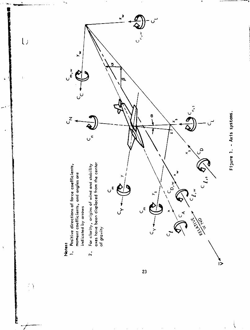
1. A x i s sys terns.
2. 140A/B Orbi ter f o r t e s t OA88.
INDEX OF DATA FIGURES
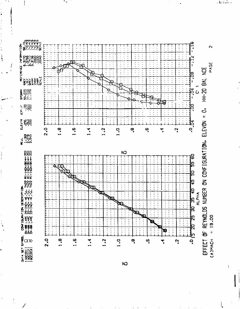
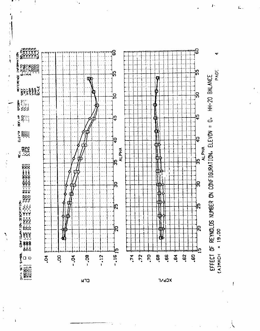
T i t l e - Effec t o f Reynolds Number on Conf i gura t i on
Elevon = 0, HH-20 Balance
Elevon = -5, HH-20 Balance
Elevon = -5, HH-19 Balance
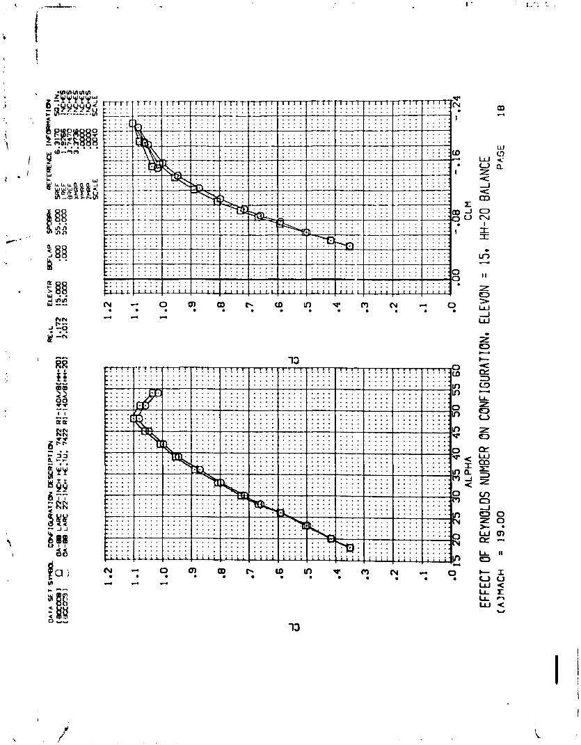
Elevon = 15, HH-20 Balance
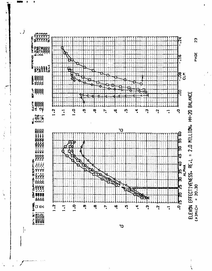
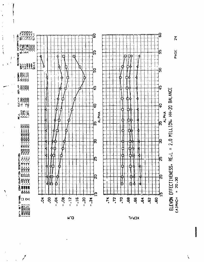
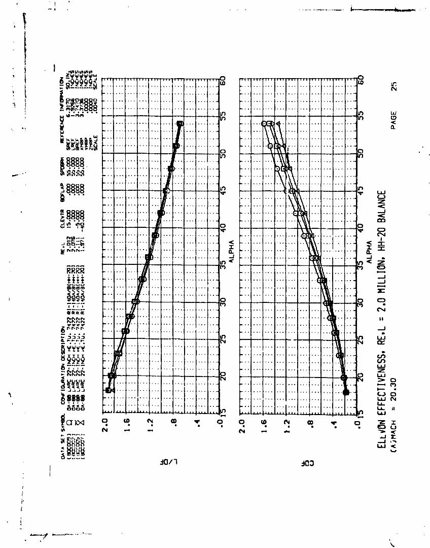
Elevon Effectiveness, Re,L = 2.0 m i l l i o n
HH-20 Balance
E f fec t o f Reynolds Number on Body Alone
HH-20 Balance
Schedule o f Coef f ic ients Y 1 ot ted :
Page
2 3
24
Schedule o f Coef f i d e n t s P l o t t e d Pages
A) CAF, CAB, CN, CL, XCP/L, CLM, CDF, L/DF vs. ALPHA CN vs. CLM CL vs. CLM

SYMBOL - b
4 M
P
4
Re ,L
v
a
B JI 4 P
Ab .
b
c.g.
!m C
S
SUBSCRIPTS b 1 8 t . OD
PLOT SYMBOL -
CP
MACH
Q( N S f 1 Q( )
RE ,L
ALPHA
BETA
PSI
PHI
WEF
LRn
SREE'
MRP
XMRP
I[MRP
r n P
N a m l C L A R I R E General
EINITION
speed of sound; m/sec, f t / s e c
pressure coef f ic ien t ; (q - p,)/q
Mach number; ~ / e
pressure; ~ / m * , psf
dynamic p r e s s b e ; 1/2pv2, ~ / m ~ , psf
unit Reynolds number; based o n body length
veloc i ty ; m/sec, f t / s ec
angle af a t tack , degrees
angle of s i de s l i p , degrees
a n g l e of yew, degrees
angle of r o l l , degrees
m d s s densi ty; kg/m3, s lugs / f t3
Reference & C. G. Defini t ions
base srea; m2, it*
wing spen o r reference spen; m, it
center of g r av i t y
reference length o r wing mean aerodynamic chord; m, f t
wing aree o r reference area; m2, f t 2
moment reference po in t
moment reference point on X ax i s
moment reference po in t on Y ax i s
moment reference po in t on Z ax is
base l o c a l s t a t i c conditions t o t a l conditions f r e e stream

N-CLAWRE (Continued )
Body-Axis System
PLOT SYMBOL SYMBOL - - IrEFTNITION
no-1-f orce coefficient; force q s
axial-force coefficient; PS
side-force coefficieat; side force as
base-f orce coefficient; qs
'Ab(pb - PCO)/~S
C Ab
CAB
' ~ r CAF
c m CIM
forebody ax i a l force coefficient, CA - CAb
pitching-moment coefficient; i t ch in mamcnt -7kT
yawing-moment coefficient; Win * Cn CYN
CBL rolling-moment coefficient; moment q,%
Stability-Axis System
l i f t coefficient; lift qs C~ CL
C~ CD
C% CDB
% CDF
cy CY
Cm CIM
drag coefficient; drag qs
base-dreg coefficient; + forebody drag coefficient; CD - C%
side-f orce c a f f i c ien t ; qs
yawing-maaent coefficient; Win mQment *.
rolling-mamcnt coefficient; rlSb
l i f t - to -drag r a t i o ; q c D
l i f t t o forebody drag r a t i o ; cL/cDI
Symbol
Xcp'l B
P lo t Symbol
BDFLAP
ELEVON
RUDDER
SPDBRK
AILRON
ELEVTR
BALANC
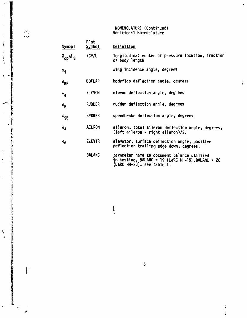
NOMENCLATURE (Continued) Addit ional Nomenclature
De f in i t i on
long i tud ina l center o f pressure locat ion, f rac t i on o f body length
wing incidence angle, degrees
bodyflap de f lec t ion angle, degrees
elevon def lec t ion angle, degrees
rudder def 1 e c t i on angl e, degrees
speedbrake def lec t ion angle, degrees
ai leron, t o t a l a i l e ron def lect ion angle, degrees, ( l e f t a i l e ron - r i g h t ai leron)/Z.
elevator, surface de f l ec t i on angle, posi t i ve def 1 e c t i on t r a i 1 i ng edge down, degrees.
?arameter name t o document balance u t i l i z e d
t n tes t i ng , BALANC = 19 (LaRC HH-19), BALANC = 20 LaRC HH-20). see tab le 1.

REMARKS
Measurement o f the 34-0 model a t the Los Angeles D iv is ion of Rockwell
I n t e r n a t i ~ n a l revealed inaccuracies i n the conf igurat ion, which d ic ta ted
the use o f unique reference dimensions and areas t o reduce the raw " a : . ~
t o c c e f f i c i e n t form.
S ign i f i can t model e r ro rs revealed were as fol lows:
1. The overa l l length o f the model was 5.5 inches f u l l scale (FS)
too long. This e r r o r i s d i s t r i bu ted w i t h 1.0 inch a t the nose and 4.5
inches a t the rear o f the fuselage.
2. The elevon hinge 1 ine was located too f a r a f t , being 2.875
inches FS i n e r r o r a t the l e f t hand t i p and 1.0 inch FS a t the r i g h t hand
t i p f o r a net e r r o r o f approximately 2.0 inches.
3 . The leading edge c u f f s were staggered; the l e f t hand c u f f was
10 t o 20 inches f u l l scale a f t o f the cor rec t s ta t i on measured p a r a l l e l
t o the FRL and the r i g h t hand c u f f was near ly correct .
4. The elevon t r a i l i n g edges were located too f a r a f t , 6.56 inches
FS on the l e f t s ide and 8.46 inches FS on the r i g h t hand. When combined
w i th a properly located leading edge, t h i s y ie lds an oversized planform.
5. The balance center was located 3.0 inches FS iorward from i t s
nominal loca t ion a t s ta t i on 1073.7 instead o f 1076.7.
Analysis o f the er rors by the Rockwell Space D iv is ion Aerodynamics
Group has l e d t o the generation o f non-standard constants t o y i e l d data
which i s i n reasonable accord w i th those obtained i n other t es t i ng pro-
grams. These values and those o f the nominal Orb i te r are presented below:

REMARKS ( ~ o n c 1"ded)
Dimension
Wing area (S)
Wing span (b)
Mean aerodynamic chord (F)
MRC, Xo s ta t i on
Elevon area, per side
Elevon moment arm, f o r appl icat ion t o incremental data only (distance from MRC t o 0.25 elevon M.A.C.)
Nominal Orhi t e r ( f u l l s ~ d l e )
2690. ft2
936.68 i n
474.81 i n
1076.7 i n
Used f o r 34-0 model ( f u l l scale)
2741.8 ft2
936.68 i n
481 .648 i n
1081.39 i n
238.93 ft2
331.89 i n
Addi t ional ly , the elevon def lect ions were measured and a l i s t o f
%RUE was obtained. U t i l i z i n g these values f o r p l o t t i n g a lso improves
the agreement of the data w i t h those obtained from other sources.
Elevon Pane 1
l e f t r i g h t
l e f t r i g h t
l e f t r i g h t
1 e f t r i g h t
Nominal de

CONFIGURATIONS INVESTIGATED
During t e s t OA88, the 140AlB vehicle was tested i n f u l l up and wing
o f f cor~f igura t ions.
The fol lowing l e t t e r designations were used to denote components of
the 140A/B conf igurat ion:
Fuselage t o the outer mold l i n e contours o f drawing VL70-000143 incorporat ing an in tegra l canopy and blended i n t o the 1408 wing by drawing VL70-000200 I r i sed
Canopy t o VL70-000143 1 i nes
Elevon of planform and sect ion o f VL70-000200 wing w i th hinge 1 ine a t Xo = 13.87. The elevon gaps are not simulated
Center p i v o t bodyflap w i th hinge l i n e a t A = 1528.3 and planform as denoted on VL70-000145 drawing
Orb i ta l maneuvering system pods mautlied 0'1 the upper rear o f the fuse1 age w i th rocket engine nozzles simulat,ed, 1 ines per VL70- 000145
Rudder ut i l izc !d w i th V8 v e r t i c a l t a i l and shown on VL70-000146A
45" sweep leading edge s ing le center 1 ines mounted v e r t i c a l t a i 1 o f modified dlamond sect ion as per VL70-000146A
VL70-000200 I w i s e d wing: 1408 wing blended t o 140A body; wing i s of 81 "/45O sweep leading edge and i s 6 inches FS th icker a t the body than 140A; a i r f o i l i s modified NASA 0011.3 a t Y = 199, 0012.64 a t theoret ica l t i p ; = +0°30', dihedral = 3'30' a t TE; t i p i s defined by VL70-00~002
The tested configu at ions were denoted as:
1 40A/B ' a t f B26 C9 E26 F7 M7 R5 "8 ': 16
Body alone = BZ6 Cg M7 R5 V8
See the Remarks section f o r model anomal ies.

TEST FACILITY DESCRIPTION
The WSA/Langley Research Center 22-inch Hypersonic He1 ium Tunnel i s
a blowdown f a c i l i t y w i th a normal operational time of 30 seconds f o r aero-
dynamic force and m e n t tests. Studies are conducted i n the 22" diameter
t e s t sect ion a t Mach numbers o f 18 t o 22 a t stagnation pressures from 300
t o 2000 ps i and a t t o t a l temperatures from 480°R t o 960°R; these t e s t I -4:
condit ions a l low f o r a Reynolds number vd r ia t i on o f 0.7 x l o6 t o 11.5 X
106 per foot .
The tunnel i s a lso equipped w i th an Electron Beam Flow V isua l iza t ion
System which allows co lo r photographs w i t h depth o f f i e l d t o be made o f
the shock system.
Operational parameters o f the contoured nozzle f low charac ter is t i cs
are ava i l able i n NASA TN D-2489, 1964, Longitudinal Characteri s t i c s o f
Several Configurations a t Hypersonic Mach Numbers i n Conical and Con-
toured Nozzles, by Arrington, Joiner and Henderson.

DATA REDUCTION
The LaRC HH-19 and HH-20 balances were used t o measure Orb i te r forces
and moments a t four Reynolds numbers. Data were converted t o standard
NASA force and moment coe f f i c i en ts and are presented about a nominal
moment reference center i n both s t a b i l i t y and body ax is systems.
Addi t ional ly , the normal force center o f pressure i s presented as
where Xcp i s the long i tud ina l distance from the inner mold 1 i n e nose
s ta t i on (Xo = 238 inches f u l l scale) t o the center o f pressure.
Reference dimensions f o r t h i s t e s t were d i s t i n c t l y non-standard and
may be found w i th an explanation as t o t h e i r o r i g i n i n the Remarks section.

, ",
TABLE I.
TEST CONDITIONS
IDATE : Dec 73
REYNOLDS NUMBER MACH NUMBER
DYNAMIC PRESSURE STAGNATION TEMPERATUF (per body l eng th ) (pounds/sq. inch) (degrees Fahrenhe~t) -
18.1 0.75 x lo6 0.65 4 5
19.0 1.15 x lo6 0.94 45 20.3 2.05 x lo6 1.56 45 21.6 4.00 x lob 2.62 45
(nominal)
-
I BALANCE UT IL IZED: LaRC HH-19
CAPACITY: ACCURACY: COEFF IC IENT TOLERANCE:
N F 0.5% SF a 0.51 A F 0.7 lbf 0.5% PM 2.5 in I b f 0.5% -- RM 0.5 in Ibf 0.5%
COMMENTS: Utilized with 35" prebend HHT dogleg sting
Applies to datasets 13 through 16

TABLE 1 . - Concluded.
EST : OA88 I IDATE : Dee 73
TEST CONDITIONS
REYNOLDS NUMBER DYNAMIC PRESSURE STAGNATION TEMPERATUR MACH NUMBER (pounds/tq. inch) (degrees Fahrenheit)
BALANCE UTILIZED: LaRC HH-20
COMMENTS:
CAPACITY: ACCURACY: COEFFICIENT TOLERANCE:
PM 7.0 i n - l b f 0.5%
RM 1 . 5 i n - l b f 0.5%
YM 2.1 in - lb f 0.5%
U t i l i z e d w i t h 35' dogleg HHT
Applies t o datasets 1 through 12


*REVISED 1;/24/74
TABLE I 11. -MODEL DIMENSIONAL DATA
MODEL COMPONENT : -JQXLB&
GENERAL DESCRIPTION : 0
NOTE: B,c, is identical to & except underside of fuselage has been
refaired to accept W l l
C: -47. REUUSE 12
DIMENSIONS FULL SCALE MODEL SCALE
5 173 Li,161
*Length (OML: Fwd Sta Xo=235),In. 1293.3 *Length (IML: ~ u d ~ t a . ~0=238),1n,=,
Max Width (@ X, =1528.3), ~ n . 264.0
Max Depth (@ x0 = i464), In.
Fineness Ratio
Max. Cross-Sectional W.88
Wetted
Base

TABLE 11 1. - MODEL DIMENSIONAL DATA - Continued.
MODEL COMPONENT : CAmPY - Cn
GENERAL DESCRIPTION : U. -6.
0 . O O b MODEL DRAWIE: S S - A O O ~ ~ ~ , RELEASE L2
DRAWING NUMBER . VL70-000143A
DIMENSIONS :
+ Length
Mox Width (e xo =
Mox Depth (e xo =
Fineness Ratio
Areo
Mox. Cross-Sectional
Plan form
Wetted
Bose
FULL SCALE MODEL SCALE

TABLE 111. - IIODEL DIMENSIONAL DATP - Continued.
MODEL C O B P O N N T : 1 I
--
MODEL SCALE: 0.0040 MO-G: S S - A O O ~ ~ ~ . REWSE 6
DRAWING KCYRER: YL70-000?00. -~0608g, -006092
DIEENS IONS : FULL-SCALE
Area - Ft 2 210.0
Span (equivalent ) , In. 349.2
I n b ' d equivalent chord, I,,
Outb'd equivalent chord , 1n. ~~ R a t i o movable surface chord/
t o t a l surface chord
A t Inb 'd equiv. chord *
A t Outb'd equiv. chord
Sweep Back .Angles, degrees
Leading Edge
, Trailin& edge
Hinge1 lne o .no
* Area Moment ( Product of o.rea & c) , F t 3
+Mean Aerodp-mic Chord, In.

MODEL COMPONENT : - -- GENERAL DESCRIPTION : ean.fipurntlnn~ nrm +*r
MODEL SCALE: 0,004
DRAWING NUMBER '
DIMENSIONS : FULL SCALE MODEL SCALE
Length (Xu= 1520 to Xo = 1613),1~. 91.000* 0.172
Max Width, ~ n . - Mox Depth (B Xo = 1520), In. 23.000 0 $092
Fineness Ratio
Areo - Pt2
- Max. Cross-Sectional - Plonform 142.6 0.0023
Wetted
Bose 41.847 o .00067,
wPbdel dim. measured from model sta . 15.20

TABLE I 1 I. - MODEL DIMENSIONAL DATA - Continued.
MODEL COMPONENT : - M
GENERAL DFSCRIPTION , ~d~ &-
W ! . E * Q d l Q b - sS400147. RE&EASE 12
DRAWING NUMBER e; -
DIMENSIONS F U L L SCALE MODEL SCALE
Length (OMS n d Sta. Xo = 1233.0),& 1 2 7 . m 1.708
Max Width (@ Yo = 1450.0), In.
Max Depth (@ xo = 1493.0), In.
Fineness Ratio
Area
Max. Cro ss-Sectional
Plan form
Wetted
Base

TABLE 111. - tlODEL DIMENSIONAL DATA - Continued.
MODEL COXPONENT: - R, d
MODEL SCALE: 0.0040 4. {
DIKENSIONS: FULL-SCALE MODEL SCALF
Area - ~t~
Span (equjvalent ) , In. I n b ' d equivalent chord , In. 91.582' 0.366 Outb'd equivalent chord , In. 50. 833 0.203 <
Rat io movable surface chord/ t o t a l surface chora
A t Inb 'd equiv. chord 0.400 I
A t Outb'd equiv. chord 0.400 - 0 - k
Sweep Back .Angles, degrees
Leading Edge
T r a i l i ~ Bdze t

MODEL 3CArJ3: 0.0040
Area (meo) - Ft 2
Planf o m Span (Theo) - In. P.;pect Ratio Rate of Taper Taper Ratio Sweep-Beck Angles, Degrees.
kading Edge * Trailing Ed.@
0.25 Element Line
Chords : Root (Theo) YP 268.500 . 1.074
w Tip (Theo) 7I.P . 10~. 1~70 d?4- MIX --u%d!s a.199--- F ~ S . s b . of .25 MAC L!&AL W.P. of .25 MAC B.L. of .25 IYIC
hrlL; - 0.000 -Q.mQ-
Airfoil Section Leading Vedde .iwle - Deg. 10.000 10.000 trail in^; Wedge I:n@e - Dcg. 11,. qza_ Leading Edge ,,Fhdius ? .or)
r4.020- 0.008
Void Area 13.17 0 2 ' -
Blanketed i.rea
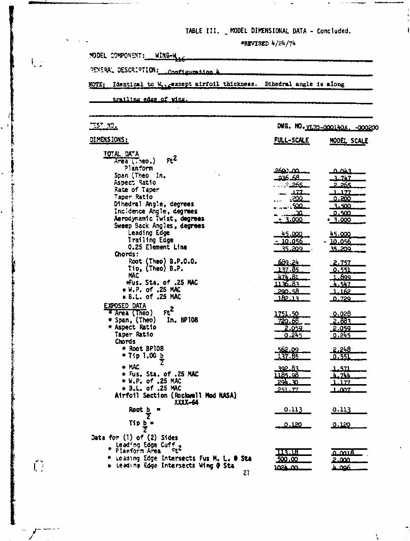
TABLE I I I. - RODEL DIKNSIONAL DATA - Concluded. I * , . *REVISED 4/24/74
WDEL 23WOYt,T: WING-Y , 1. ;
T Y C S A ' , DESCPPTXON:- &
NOTE: Identical to W,,#xcept a i r f o i l thicknees. Mhedral angle is along
TOTAL DATA i \ r e a - c ~ e o . ) Ft2
Planform Span (Theo In. Aspect Qatio Rate o f Taper Taper Ratio Dihedral Png?e, degrees I nc I dence A?g 1 e , degrees Aemdynami c Twi st, degrees Sweep Back Angles, degrees
Leading Edge Trai l i ng Edge 0.25 Element Line
chords: Root T h t ~ B.PwOoOw T ~ D , Theo BOPw MAC
t I #us, Sta. o f ,25 MAC
* W, P. of .25 MAC * B.L. of 2 5 MAC
EXPOSED DATA * Area (The01 Ft2 + ~pan,-(~h&) Xn. BPI08 + Aspect Ratio
Taper Ratio Chords
* Root BPI08 * Tfp 1.00 b
T
*MAC L
* Fuse S t a b O f m25 MAC * W.P. of .25 MAC * B.Lw of .25 MAC
A i r fo i l Section ( Aclaell Mod WA) XXXX-64
Root2 =
h t a for (1) o f (2) Sides Lead4ng Edge Cuff * Planforn et2
* Lcaalnp Edge Intersects Fur N. L. @ Sta + Leadl nr Edge Intersects Uing d Sta
21

RUN NUMBER MACH NO.
.- - - 20.3
21.6
19.0
- -
20.3
Zi. 6
20.3
19.0
19.0
20.3
21.6
20.3
19.0
18. 1
19.0
20.3
21.6
1
DYNAMIC PRESSURE
@W
1.5813
2.6170
0.9623
-
- 1.5703
2.6275
1.5977
0.9567
0.9614
1.5782
2.6236
1.5821
0.9708
0.6785
0.9792
1.5864
2.6466
--
Not
es:
1 . P
osit
ive d
ire
cti
on
s o
f fo
rce
co
eff
icie
nts
,


DATA FIGURES

MT
A SET
SV
- C
6C
IQR
AT
lOJ
OE
SC
RIP
TIW
E
IL
ELEV
TR
-LA
P
sm
m
REF
EREM
E w
mr
m
OA
-ekI
LA
W ?
Z- I
UH
I-€
.TU
. 74?
2 R
I-I4
M/B
IH(-
X)I
1.1
63
,000
.#
K)
55.0
00
%F
6.3
170
=.IN.
0A-8
B
LAR
C
=-IN
CH
74
22 R
I-1
40
A/B
[W-m
) 2.4
16
.000
-0
00
55.0
00
LR
EF
1.
9266
IhCHEs
~-W
~A
R(:
22
-lK
n~
.Tu
.74
22
Rl-
14
~/8
[m-I
Ol
3.9
45
.DO
0 .000
55.0
00
SE
F
X- 3.7
470
IhC
cfs
3.3736
IKd
S
Ye
.O
W0
INC
HES
2- .0
000
IK*S
SC
ALE
A
04
0
SC
ME
ALP
HA
EFFE
CT O
F RE
YNOL
DS N
UMBE
R ON
CON
FIGU
RATI
ON,
ELEV
ON =
0,
HH-2
0 BA
LANC
E C
AJY
AC
H
= 1
9.0
0
PA
GE
ALP
HA
3 YYY <<< - A A A

1 sen ...
iii YYY
I l l ..... . . . . . . . . 1 : : . : I * @ \ : . . . 1 . . : . 1 . . : . 1 . . : : I . . . . I 1 : . . . 1 . . . . I 1 --- . . . . . . . . . . . . . . . . . . . . . . . . . . . . . . . . . . . . . . . . . . . . . aaa . . . . . . . . . . . . . . . . . . . . . . . . . . . . . . . . . . . . . U
' I " ' .-
I:
J
U
ALP
HA
..
..
.
..
.
..
..
.
..
.
..
..
.
..
.
..
..
.
..
.
..
..
.
..
.
..
..
.
..
.
..
..
.
..
.
..
..
.
..
.
..
..
.
..
.
7.
ALP
HA
EFFE
CT O
F RE
YNOL
DS N
UMBE
R ON
CON
FIGU
RATI
ON,
ELEV
ON =
Op
HH
-20
BALA
NCE
(AIM
AC
H
= 1
9.0
0
PA
GE
4


ALP
HA
EFFE
CT O
F RE
YNOL
DS N
UMBE
R ON
CON
FIGU
RATI
ON,
ELEV
BN =
-5.
HH-2
0 BA
LANC
E C
AIM
AC
H
= 1
9.0
0
PA
GE
6

--- I l l

: : : ; I ; ; ; ; . . . - . . . . . . . . . . . . . I . . . . . .

wr*
SET
s
ne
~ C~
SIC
LR
AT
I~ I
JE
SC
RIP
TI~
R
EaL
E
LEV
TR
-LA
P
REF
EREN
CE
INm
TIm
1
Q
m-m
LA
RC
22
-IK
~ &
.ru.
7m
n
!-tr
ow
ef~
c-m
l I .ln
-5.m
.OOO
5S
.m
sAEF
6.31~ 50.1~.
t BC=O~
I O
A-m
LA
K
22
:hC
n t
-€.r
u.
74
22
1?
1-1
4m
/~(r
n-2
01
2
.1
-5
.000
.000
55.0
00
LAE
F 1.9
266
ICM
S
1 BOC006 1
m
-W L
A*
22-1
- t€
.Tu
. 7
42
2 R
I-L
4M
/B1
H(-
X))
4.0
49
-5.m
.om
ss.#K,
WE
F
XtU
P
3.7
47
0
lhCnES
3.
lKN
S
Vm
P
.000
0 I
SM
S
2- .am
rhC
*s
SC
ALE
,0
043
SC
ALE
EFFE
CT
CA
IMA
CH
ALP
HA
ALP
HA
OF R
EYNO
LDS
NUMB
ER O
N CO
NFIG
URAT
ION,
EL
EVON
1-5.
HH-2
0 BA
LANC
E =
19.0
0
PA
GE
9


ALP
HA
EFFE
CT O
F RE
YNOL
DS N
UMBE
R ON
CON
FIGU
RAT I
ON,
2 .o
1.8
1.6
1.4
1.2
1.0
.8
.6
04
02
- ....
....
....
....
....
....
....
....
....
....
....
....
....
....
... -
-.,.
....
....
....
....
....
....
....
....
....
....
... .
..-
....
....
....
....
....
....
....
....
....
....
....
....
....
..
.,.-
'O - 0
4 0
CLM
ELEV
ON =
-St
HH-1
9 BA
LANC
E P
AG
E
12


DA
TA
SE
T SY
- . C4
002
.oo
- 002
I:
J
u
- -0
4
- -0
6
- .O
8
-.lo
ALP
HA
J
\
h
U
X
..
..
.
..
.
ALP
HA
EFFE
CT O
F RE
YNOL
DS N
UMBE
R ON
CON
FIGU
RATI
ON,
ELEV
ON =-5,
HH- 1
9 BA
LANC
E CAIMACH
= 18.1
0
PA
GE
14


DA
TA S
T SV
)+1Q
C
WI
wA
Tl
m D
ES
CR
lPT
Im
=,L
E
LEV
TR
BY
LA
P
SP
DB
W
RE
FE
WM
E
IwO
Rw
AT
!m
[ Q
A-W
LAR
C ~
-]
KH
+€
.TU
. 7422 R
I-I4
OA
/BI)
XI)
1
.I??
15.-
.a 55.000
'$:
6.3!70
5Q.I
N.
0A-8
8 LA
RC
2
3-I
rS
~ nE
.TU
. 7
42
2 ~
1-1
40
~/B
(rn
-t0
) 2
.01
2
1S.O
ZD
,000 55.000
rj);
r 1.
9753
6 !kc+
18
0ix
91
3
.74
70
,K+
+tS
X
PR
P
3.3736
lIvC
hES
VM
RP
.OCm
INCHES
ZW
.OC30
INCHES
YA
LE
.a
34
3
SC
ALE
.12 . 10
.08
-06
-04
002
moo
ALP
HA
ALP
HA
EFFE
CT
AIMACH
OF R
EYNO
LDS
NUMB
ER O
N CO
NFIG
URAT
ION,
ELE
VON
= 15
n HH
-20
BALA
RCE
= 19.0
0
PA
GE


'I-
ALP
HA
ALP
HA
ELt
JOd
EFFE
CTIV
ENES
S. RE.
L =
2.0
MIL
L ION. HH-20
BALA
NCE
CAiM4CH
= 20.30
PA
GE
2
5

ALP
HA
.OO
8
.004
.
,.
.
. .
. .
..
..
.
,.
.
.ooo
- ,004
- .008
ALP
HA
EFFE
CT O
F RE
YNOL
DS N
UMBE
R ON
BOD
Y AL
ONE*
HH
-20
BALA
NCE
CA
IMA
CH
= 19.00
PA
GE
26


ALP
HA
EFFE
CT O
F RE
YNOL
DS N
UMBE
R ON
BOD
Y AL
ONE,
HH
-20
BALA
NCE
CAIMACH
= 19.00
CLM
PA
GE
28


ALP
HA
ALP
HA
EFFE
CT O
F RE
YNOL
DS N
UMBE
R ON
BOD
Y AL
ONE,
HH
-20
BALA
NCE
CAIMACH
= 19.0
0
PA
GE

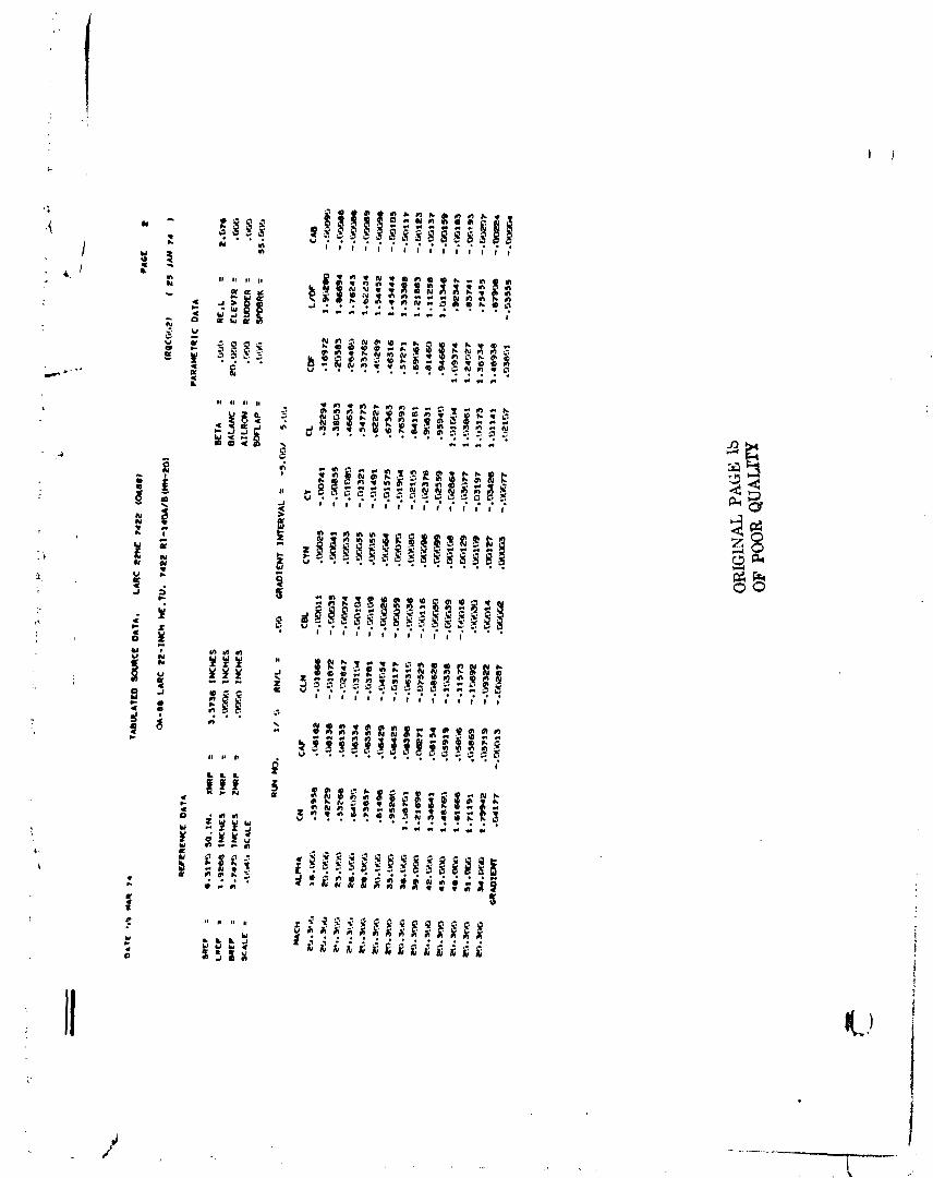
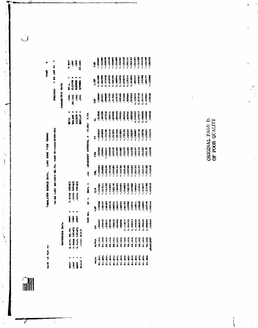
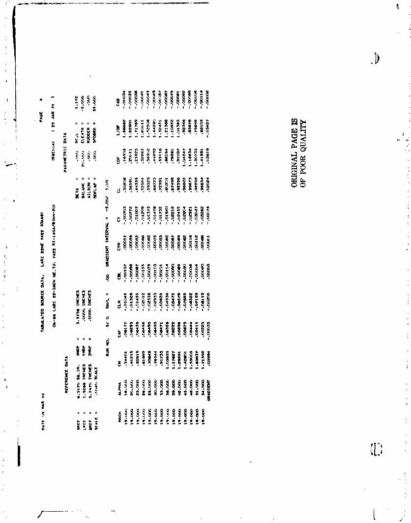
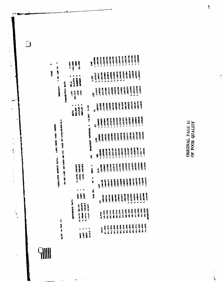
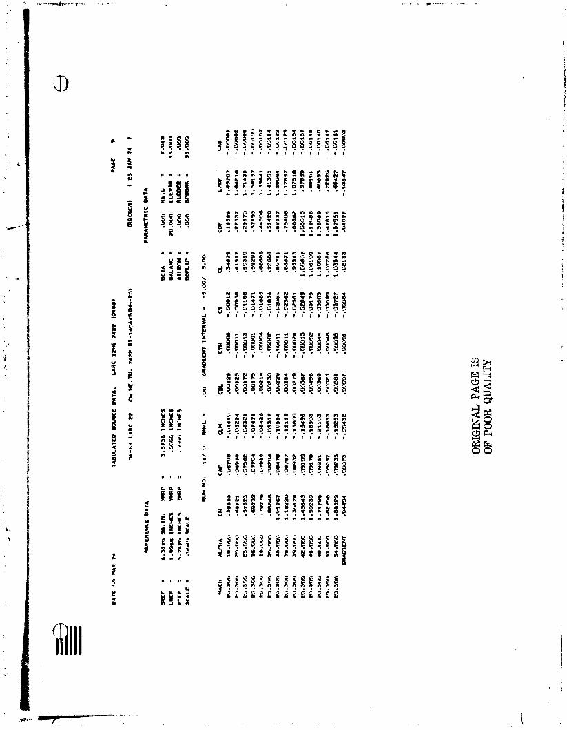
APPEND1 X
TABULATED SOURCE DATA
Tabulations of plotted data are available on request from Data Management Services

OR
IGW
AL
PA
GE
lb
OF P
OO
R Q
UA
LITY
PA
CE
2
(RQ
CW
jrl2
l f
25
IA
N 7
4
)
PA
RA
ME
TR
IC D
AT
A

b n p n : e j 3 ~ g $ ; # ; p L - g
I41 91 . . 4q?4 , , q ~ g ! P A
1 1 I 1 1 l 1 1 1 1 1 1 1 1 1
* a E I B ,

CLM
-.
M3
74
-.%
I60
- .C
f.i1
18
-.MIm
-.cxw
Vs
- .MS
%
-.013m
- .rG?s
:a - .D
!uQ
-.r5
4730
- .C.u
287
-.S
t71
0
- .'as%e
-.re
376
- . wa
s5
OR
I(X
VA
L PA
GE
IS
OF P
OOR
QU
ALI
TY

a.3
1m
=.I
N.
YW
P
= 1
.3~
38
ttuklS
I.9
Eb
. IN
CW
S
VlR
P
= .?
KE
G
INC
HE
S 3
.v.m
IN
CH
ES
Z
(IR
f =
.rSJT
IJ INCkES
.IflJ
.li S
CA
LE
CL*
- .Id4
40
- .C1
5224
- .?
I632
1 - .D
74?
- .5
84
26
-.
09
31
7
-. 10
55
4
-.1
21
12
-.
1U
Ha
-.I5
49
6
-.le
v33
-.Z
llQ
3
- . 18
63
3
-.IS
25
3
- .?+54
32
.CYJ
G
RID
lEW
T
INT
ER
VA
L =
-5
.m/
5."
U
OR
IGIN
AL
PAG
E I
S OF P
OO
R Q
UA
LITY


- W a e n *
N a , O A
k' m X p X a a ; % 3 2

TAB
UA
TLO
X
XR
CL
O
AT*
. L
LR
C z
m ra
zz ta
m1
6*-
80
LA
RC
22-I
NC
h
hE
.TU
. 7422 R
l-1
4'3
AlB
(W-1
9)
CL
M
. -.
Q1153
- .ti1531
-.?I1
230
-.o
15
m
- .01
741
-.%
el2
4
-.?12716
- .03048
-.rA
722
- .?i6
*4
-.?
17211
- .?
17985
- .'-a
349
- . K#-
i23?
1
OR
IGIN
AL PAGE IS
OF BOOR
QU
ALI
TY
.?S
t -
5.
m
.m
55
.wc
CAB
-.w
ill$
! - .
W.ilL
i9
-.?f.i
lll
-.M
11
9
-.W
12
4
-.W
13
4
- .'&
I47
- .Lii165
-. Wl
82
-.L
W198
-.w
:i13
- . 'Xi
2E
6
- .'X
i247
- .?#.-I?
%-.o

m e n W W Y
PPf LI..

WF
EU
CN
Cf
DA
TA
MC
?
= L
RC
C
= O
RC
?
= S
C4
LC
=
MACH
21 . 6'3
.3
21 .-
21 *=a
21 .u
.X,
21
.m*
21 .W
-Y<O
.M
CR
AD
IMT
IN
TE
RV
AL
=
-5.-
5.m
OR
IGIN
AL
PA
GE
IS
OF P
OO
R Q
UA
LITY