in-air microfluidics enables rapid fabrication of ... · than chip-based droplet microfluidics....
TRANSCRIPT

SC I ENCE ADVANCES | R E S EARCH ART I C L E
ENG INEER ING
1Physics of Fluids Group, Faculty of Science and Technology, University of Twente,P.O. Box 217, 7500 AE Enschede, Netherlands. 2Department of DevelopmentalBioEngineering, MIRA Institute for Biomedical Engineering and Technical Medicine,University of Twente, P.O. Box 217, 7500 AE Enschede, Netherlands.*These authors contributed equally to this work.†Present address:Wyss Institute for Biologically Inspired Engineering and JohnA. PaulsonSchool of Engineering and Applied Sciences, Harvard University, Cambridge, MA02138, USA.‡Corresponding author. Email: [email protected] (C.W.V.); [email protected] (M.K.)
Visser et al., Sci. Adv. 2018;4 : eaao1175 31 January 2018
Copyright © 2018
The Authors, some
rights reserved;
exclusive licensee
American Association
for the Advancement
of Science. No claim to
originalU.S. Government
Works. Distributed
under a Creative
Commons Attribution
NonCommercial
License 4.0 (CC BY-NC).
Dow
nload
In-air microfluidics enables rapid fabrication ofemulsions, suspensions, and 3D modular (bio)materialsClaas Willem Visser,1*†‡ Tom Kamperman,2* Lisanne P. Karbaat,2
Detlef Lohse,1 Marcel Karperien2‡
Microfluidic chips provide unparalleled control over droplets and jets, which have advanced all natural sciences.However, microfluidic applications could be vastly expanded by increasing the per-channel throughput anddirectly exploiting the output of chips for rapid additive manufacturing. We unlock these features with in-airmicrofluidics, a new chip-free platform to manipulate microscale liquid streams in the air. By controlling thecomposition and in-air impact of liquid microjets by surface tension–driven encapsulation, we fabricate mono-disperse emulsions, particles, and fibers with diameters of 20 to 300 mm at rates that are 10 to 100 times higherthan chip-based droplet microfluidics. Furthermore, in-air microfluidics uniquely enables module-based produc-tion of three-dimensional (3D) multiscale (bio)materials in one step because droplets are partially solidified in-flight and can immediately be printed onto a substrate. In-air microfluidics is cytocompatible, as demonstratedby additive manufacturing of 3D modular constructs with tailored microenvironments for multiple cell types. Itsin-line control, high throughput and resolution, and cytocompatibility make in-air microfluidics a versatile plat-form technology for science, industry, and health care.
ed
on March 31, 2020http://advances.sciencem
ag.org/from
INTRODUCTIONMicrofluidics has become a cornerstone platform technology for testingand production of microscale droplets, particles, and fibers as well asencapsulation of food, drugs, and cells (1–4). This versatility originatesfrom the use ofmicrofluidic chips, which combine fully predictable flowbehavior with in-line liquid manipulation and monitoring (5, 6). As atypical example, a coaxial chip geometry is shown in Fig. 1A. Here,liquid is ejected from the inner channel and pulled off by an outer co-flowing liquid, resulting in amonodisperse train of droplets. Alternativedesigns and more advanced chips have been used for the productionof microdroplets, microparticles, and microfibers with a wide variety ofsizes, shapes, and compositions (7–10). However, despite their successregarding laboratory-scale analysis and production, conventional mi-crofluidic chips have intrinsic limitations that hamper translation ofsuccessful concepts into clinical, pharmaceutical, or industrial products(11–13). First, microfluidic droplet generators are typically operated at aper-nozzle throughput of 1 to 10 ml/min because of a transition frommonodisperse dripping to polydisperse jetting for higher flow rates(14). Second, the design, fabrication, and operation of microfluidic de-vices require advanced skills and specialized equipment, which are notalways compatible with existing production processes or environmentsoutside the laboratory (6, 15). Third, microfluidic chips can only be op-erated with at least one nonsolidifying flow, which is required toseparate droplets, particles, or fibers from each other and the channelwalls (3). Removing this coflow (for example, oil) is nontrivial, whichlimits clinical translation and implies that the output of chips is limitedto particles in solution (that is, emulsions and suspensions), whereasstacking of particles into solid three-dimensional (3D) constructs could
enable printing of modular materials in one step. An off-chip approachwould eliminate all these wall-induced limitations and therefore unlocknew applications of microfluidics.
Here, we present in-air microfluidics (IAMF), a new chip-free plat-form technology that enables in-flight (that is, on-the-fly) formationof droplets, fibers, and particles and their one-step deposition into3D constructs with a modular internal architecture. In concept, micro-fluidic channels are replaced by micrometer-sized liquid jets that arecombined in the air, as shown in Fig. 1B. This approach retains the
Chip-based
microfluidics
In-air
microfluidics
10−100 × faster
Emulsions andsuspensions
3D modular(bio)materials
In-line control
Channels
Jets
Bath (Fig. 3) Substrate (Fig. 4)
Dynamics(Fig. 2)
A B
Fig. 1. Concept of IAMF and guide to the article. (A) Chip-based microfluidics en-ables in-linecontrol overdroplets andparticles,making it a versatile platformtechnology.A chip designwhere droplets (blue) are transported by a coflow (pink) is shown. (B) IAMFmaintains the in-line control of chip-based microfluidics but relies on jet ejection andcoalescence into air. Therefore, a wide range of droplets and particles can be producedat flow rates typically twoorders ofmagnitudehigher thanwith chip-basedmicrofluidics.When combining reactive, solidifyingmicrojets, IAMF also enables on-the-fly productionand direct deposition of microparticles into 3D multiscale modular (bio)materials.
1 of 8
SC I ENCE ADVANCES | R E S EARCH ART I C L E
on-the-fly processing capacity of chip-based microfluidics but enablesorders of magnitude higher throughput. In this work, we (i) discuss thephysical principles that underlie IAMF; (ii) leverage surface tension–drivenencapsulation to achieve in-air liquid-liquid encapsulation; (iii) exploitthese mechanisms to realize a library of droplets, particles, and fiberswith distinct shapes, compositions, and sizes; and (iv) demonstrate thatthese in-air formed particles can be used as cytocompatible “buildingblocks” for the one-step printing of larger 3D (bio)materials with vari-ousmodular architectures. Finally, we discuss IAMF in relation to othertechnologies, as well as potential directions for future work.
on http://advances.sciencem
ag.org/D
ownloaded from
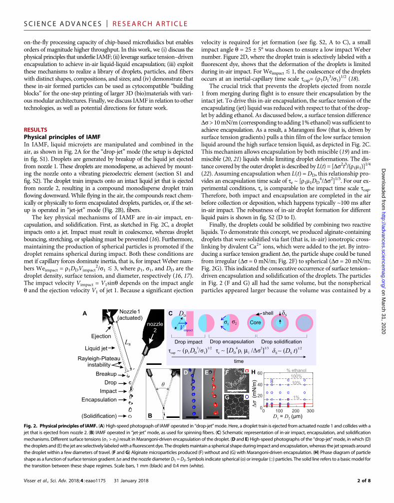
RESULTSPhysical principles of IAMFIn IAMF, liquid microjets are manipulated and combined in theair, as shown in Fig. 2A for the “drop-jet”mode (the setup is depictedin fig. S1). Droplets are generated by breakup of the liquid jet ejectedfrom nozzle 1. These droplets are monodisperse, as achieved by mount-ing the nozzle onto a vibrating piezoelectric element (section S1 andfig. S2). The droplet train impacts onto an intact liquid jet that is ejectedfrom nozzle 2, resulting in a compound monodisperse droplet trainflowing downward. While flying in the air, the compounds react chem-ically or physically to form encapsulated droplets, particles, or, if the set-up is operated in “jet-jet” mode (Fig. 2B), fibers.
The key physical mechanisms of IAMF are in-air impact, en-capsulation, and solidification. First, as sketched in Fig. 2C, a dropletimpacts onto a jet. Impact must result in coalescence, whereas dropletbouncing, stretching, or splashing must be prevented (16). Furthermore,maintaining the production of spherical particles is promoted if thedroplet remains spherical during impact. Both these conditions aremet if capillary forces dominate inertia, that is, for impact Weber num-bers Weimpact = r1DDVimpact
2/s1 ≲ 3, where r1, s1, and DD are thedroplet density, surface tension, and diameter, respectively (16, 17).The impact velocity Vimpact = V1sinq depends on the impact angleq and the ejection velocity V1 of jet 1. Because a significant ejection
Visser et al., Sci. Adv. 2018;4 : eaao1175 31 January 2018
velocity is required for jet formation (see fig. S2, A to C), a smallimpact angle q = 25 ± 5° was chosen to ensure a low impact Webernumber. Figure 2D, where the droplet train is selectively labeled with afluorescent dye, shows that the deformation of the droplets is limitedduring in-air impact. For Weimpact ≲ 1, the coalescence of the dropletsoccurs at an inertial-capillary time scale tcap= (r1D1
3/s1)1/2 (18).
The crucial trick that prevents the droplets ejected from nozzle1 from merging during flight is to ensure their encapsulation by theintact jet. To drive this in-air encapsulation, the surface tension of theencapsulating (jet) liquid was reduced with respect to that of the drop-let by adding ethanol. As discussed below, a surface tension differenceDs > 10mN/m (corresponding to adding 1% ethanol) was sufficient toachieve encapsulation. As a result, a Marangoni flow (that is, driven bysurface tension gradients) pulls a thin film of the low surface tensionliquid around the high surface tension liquid, as depicted in Fig. 2C.This mechanism allows encapsulation by both miscible (19) and im-miscible (20, 21) liquids while limiting droplet deformations. The dis-tance covered by the outer droplet is described by L(t) = [Ds2t3/(r1m1)]
1/4
(22). Assuming encapsulation when L(t) =DD, this relationship pro-vides an encapsulation time scale of te ~ [r1m1DD
4/Ds2]1/3. For our ex-perimental conditions, te is comparable to the impact time scale tcap.Therefore, both impact and encapsulation are completed in the airbefore collection or deposition, which happens typically ~100 ms afterin-air impact. The robustness of in-air droplet formation for differentliquid pairs is shown in fig. S2 (D to I).
Finally, the droplets could be solidified by combining two reactiveliquids. To demonstrate this concept, we produced alginate-containingdroplets that were solidified via fast (that is, in-air) ionotropic cross-linking by divalent Ca2+ ions, which were added to the jet. By intro-ducing a surface tension gradient Ds, the particle shape could be tunedfrom irregular (Ds = 0 mN/m; Fig. 2F) to spherical (Ds = 20 mN/m;Fig. 2G). This indicated the consecutive occurrence of surface tension–driven encapsulation and solidification of the droplets. The particlesin Fig. 2 (F and G) all had the same volume, but the nonsphericalparticles appeared larger because the volume was contained by a
March 31, 2020
Drop
Nozzle 1(actuated)
Rayleigh-Plateauinstability
A
Liquid jet
Impact
Breakup
Ejection
nozzle2
B
Encapsulation
(Solidification)
Drop encapsulation Drop solidification
00
D = D (μm)1 2
Δσ
(mN
/m)
300100 200
20
40
60% ethanol
δSC
D E F H
DD
σ1 σ2
shell
Core
θ
Vimpact
LΒ Drop impact
100%
10%
1%G
time
3 1/2τ ∼ ( D /σ ) cap 1 D 1 τ ∼ e
4 2 1/3[D μ /Δσ ]D 1 11/2δ ∼ (D t) S S
ρ ρ
Fig. 2. Physical principles of IAMF. (A) High-speed photograph of IAMF operated in “drop-jet”mode. Here, a droplet train is ejected from actuated nozzle 1 and collides with ajet that is ejected from nozzle 2. (B) IAMF operated in “jet-jet”mode, as used for spinning fibers. (C) Schematic representation of in-air impact, encapsulation, and solidificationmechanisms. Different surface tensions (s1 > s2) result in Marangoni-driven encapsulation of the droplet. (D and E) High-speed photographs of the “drop-jet”mode, in which (D)the droplets and (E) the jet are selectively labeledwith a fluorescent dye. Thedropletsmaintain a spherical shapeduring impact and encapsulation,whereas the jet spreads aroundthe droplet within a few diameters of travel. (F and G) Alginate microparticles produced (F) without and (G) with Marangoni-driven encapsulation. (H) Phase diagram of particleshape as a function of surface tension gradientDs and the nozzle diameterD1 =D2. Symbols indicate spherical (o) or irregular (□) particles. The solid line refers to a basicmodel forthe transition between these shape regimes. Scale bars, 1 mm (black) and 0.4 mm (white).
2 of 8

SC I ENCE ADVANCES | R E S EARCH ART I C L E
http:/D
ownloaded from
bag-like shape. Figure 2H shows the particle shape as a function of thesurface tension gradient and the nozzle size. The regime transition fromirregular to spherical particles was observed for Ds ≈ 5 mN/m,corresponding to adding a minimum amount of 0.3% ethanol.
It is surprising that the particle shape can be controlled by combiningsurface tension–driven encapsulation and solidification because even athin solid front could potentially inhibit theMarangoni flow. Toprovidea first rationalization of mechanism, we hypothesize that encapsulationis achieved if the surface tension gradient exceeds the strength of the so-lidifying film. The thickness of this film is estimated as ds = (DSte)
1/2,whereDS≈ 10−9m2 s−1 is the diffusion constant of CaCl2 into the gel (23).The strength of the film is estimated as sfds, where sf ≈ 104 Pa is thefracture stress of a0.5%alginategel (24). Byequatingsfds =Ds and solvingfor Ds, one obtains the solid line in Fig. 2H. For themeasured parameterregime, the expected film strength lies between 2 and 5mN/m, which isclose to the experimental threshold Ds ≈ 5 mN/m. However, the pre-dicted dependence on the diameter is not observed, possibly because thetime-dependent viscosity gradients are ignored in our simplifiedmodel.
Engineering droplets, particles, and fibersFigure 3 shows droplets, particles, and fibers as produced by tuningthe control parameters of IAMF. First, different material compositionswere examined while operating the setup in drop-jet mode (Fig. 3A andtable S1). Coalescing water droplets onto a surfactant-containing fluoro-carbon oil jet (withDs =50± 5mN/m) readily enabled the production of
Visser et al., Sci. Adv. 2018;4 : eaao1175 31 January 2018
monodisperse water-in-oil (w/o) emulsions, as shown in Fig. 3B. More-over, collecting thesew/o droplets in surfactant-containingwater resultedin w/o/w double emulsions (Fig. 3C). IAMF also enabled oil-free produc-tion of monodisperse solid particles such as alginate microspheres, asshown in Fig. 3D. Alternatively, liquid-filledmicrocapsules were producedby coalescing CaCl2 droplets onto an alginate jet with reduced surface ten-sion, as shown in Fig. 3E and fig. S3A. Solid-filled capsules were made byadding an in situ cross-linkable dextran-tyramine–based hydrogel pre-cursor to the droplets and its cross-linker to the intact jet, as shown in Fig.3F. IAMF is also compatible with slower (that is, not in-air) solidifyingmaterials by leveraging alginate as a structural template (fig. S4) (25).
The droplet or particle sizes could be tuned bymore than an orderof magnitude by varying the nozzle diameter and actuation frequency(Fig. 3G). As shown in Fig. 3 (H to K), monodisperse alginate micro-gels with diameters ranging from 20 mm (at 0.2 ml/min) to 300 mm (at6.5 ml/min) were produced by using nozzles with different diameters(overview photos are shown in fig. S3, B and C). The droplet or particlediameter could be fine-tuned by altering the actuation frequency f, asshown in Fig. 3K. The probability density function (P) of the particlesize revealed monodisperse particles with a coefficient of variation of<5% (the SD divided by the mean), as plotted in Fig. 3K and fig. S5.
The particle shape was controlled by altering the velocity ratio be-tween the jets, as shown in Fig. 3 (L to N). Increasing the velocity of theintact jet while maintaining the velocity of the droplets resulted in theformation of elongated particles, as shown in Fig. 3 (M and N) (details
on March 31, 2020
/advances.sciencemag.org/
Outer
InnerA
Water-alg-waterAlginate-waterWater-oil-water Dex-TA -alg-waterWater-oil
3D confocalB C D E F
K100 µm50 µm
250 µmf
D = D = 20 µm1 2
D (µm)D
P
0 100 200 3000
0.1
RL M N
Co
mp
osi
tio
nS
ize
Sh
ape
Th
rou
gh
pu
t
V2
V1
L10 100 1000
10−3
10−2
10−1
100
101
102
103
We g
= 0
.2
We =
1
Ca =
0.1
1 mHz 1 kHzIn-air MF
Chip-based
droplet MF
Per-
nozz
le flo
w r
ate
(m
l/min
)
Diameter (µm)
1 Hz
V / V = 1.52 1 V / V = 1.92 1
L << LBPO L ~ LBQ
D =D = 20 μm1 2G H 100 μmI 250 μmJf
D1
D2
Fig. 3. IAMF enables high-throughput production of monodisperse microemulsions and microsuspensions with various compositions, sizes, and shapes. Schematicdiagrams (left) indicate the relevant control parameters. (A to F) IAMF operated in “drop-jet” mode enabled the production of monodisperse (B) w/o emulsions, (C) doubleemulsions, (D) spherical particle suspensions, and (E) single-material and (F) multimaterial core-shell particles. alg, alginate; dex, dextran; TA, tyramine. (G to K) Tuning the mi-croparticle size. (H to J) Particles produced using nozzle diameters of 20, 100, and 250 mm, respectively. (K) Probability P of the particle size as a function of nozzle diameter(indicated per curve) and actuation frequency. Colors from black to pale blue indicate increasing actuation frequencies of 2.3, 3.5, 4, 4.5, 5, 6, 7, and 8 kHz. (L to N) Elongatedparticles were made by increasing the relative jet velocity. (O) IAMF operated in “jet-jet”mode enabled the production of (P) straight and (Q) pearl-lace morphologies.(R) Throughput as a function of nozzle diameter for IAMF and chip-based droplet microfluidics (MF). Themaximumper-nozzle throughput of monodispersed droplet productionusing chip-basedmicrofluidics is limited by Ca = 0.1 andWe = 1. The production throughput window of IAMF is determined byWeej = 1 (that is, minimum) andWeg = 0.2 (that is,maximum). Green circles are data points obtained using our IAMF setup. Red squares are data points obtained frompreviously reported studies ondropletmicrofluidics (2, 44–52).Droplet production frequencies are indicated with gray dashed lines. Scale bars, 200 mm (unless otherwise indicated).
3 of 8

SC I ENCE ADVANCES | R E S EARCH ART I C L E
http://advances.scienD
ownloaded from
are provided in section S1 and fig. S6). Microfibers were produced byoperating the same setup in the jet-jet mode (Fig. 3O), as enabled bysimply moving the nozzles closer to each other. First, fibers of homoge-neous thickness were produced as shown in Fig. 3P, where the cross-linker solution impacts with the gel precursor solution close to nozzle 1.With nozzle actuation turned on while moving the jet’s impact locationcloser to the breakup point (that is, L → LB), we could produce fiberswith periodic thickenings (that is, “beaded fibers”), as shown in Fig. 3Qand fig. S3 (D to F).
The diameter and throughput of IAMF-based droplet and par-ticle generation are compared to conventional chip-based dropletmicrofluidics in Fig. 3R. Because IAMF is based on jetting, the low-er flow rate of IAMF is bounded by the ejection Weber numberWeej = r1V1
2D1/s1 > 1 (fig. S2). The upper production rate ofIAMF is presumably limited by wind-induced breakup of the jetor droplet train, which occurs for gas Weber numbers Weg = rg/rWeej > 0.2, where rg is the density of the gas (26). In contrast, theproduction of monodisperse droplets using microfluidic chips re-quires operation within the squeezing or dripping regime, which isbound by Weej ≲ 1 and capillary numbers Ca = mcVc/s ≲ 0.1,where mc and Vc denote the outer phase’s viscosity and velocity,respectively, and s denotes the interfacial tension between the li-quids (14). These constraints imply that IAMF is intrinsically fasterthan chip-based droplet microfluidics. The production rates ofIAMF are compared with existing conventional microfluidic drop-let generators confirmed in Fig. 3R, revealing that IAMF is typically100 times faster than chip-based droplet microfluidics. Hence, asingle IAMF nozzle is able to produce droplets at similar produc-tion rate as compared to an up-scaled microfluidic chip consistingof 364 parallelized droplet generators (27). In section S3, we con-
Visser et al., Sci. Adv. 2018;4 : eaao1175 31 January 2018
cisely compare IAMF to alternative droplet and particle productionplatforms.
Additive manufacturing of modular (bio)materialsThrough direct deposition of in-air formed particles or capsules onto asubstrate, IAMF enables printing of 3Dmultiscale modularmaterials inone step. To validate this approach, an alginate jet with reduced sur-face tension was impacted onto CaCl2-containing droplets, resultingin a stream of shape-stable core-shell alginate particles, as shown inFig. 3 (E and F). Upon deposition onto a substrate, these soft particlesstick to the constructwithout entraining any visible air bubbles and pro-vide sufficient structural support for 3D freeforms (Fig. 4A). As an ex-ample, we created a hollow hydrogel cylinder by the directed depositionof such core-shell particles onto a rotating substrate (Fig. 4B and movieS1). The microscale architecture of the modular freeform could bealtered by tuning the microparticle composition. For example, single-material core-shell particles formed a liquid-filled foam (Fig. 4C),whereas multimaterial core-shell particles formed a multimaterial solidconstruct (Fig. 4D). Shape-stable constructs could also be formed ontosubstrates with an arbitrary inclination angle—and even upside-down—as demonstrated by omnidirectional deposition using a handheldIAMF device (fig. S7 and movie S2).
Furthermore, IAMF could be readily used for one-step generation ofinjectablemodularmaterials by combining rapidly (that is, in-air) solid-ifying droplet cores and slowly (that is, after injection) solidifyingdroplet shells, as shown in Fig. 4E. Upon deposition, particles or fiberswere lubricated by their still liquid shell that solidifies after themold hasbeen filled. As an example, we filled a bone-shaped mold with in-airformed particles (Fig. 4, F to H) and released the intact construct aftercross-linking. Themicro- andmesoscale architectures consisted of stem
on March 31, 2020
cemag.org/
Injectable
1. In-air core solidification
E
ααIn-air shell solidification
Modular freeform
Printable A Multimaterial solidD
Dextran Alginate
Dextran Alginate MSC
Cell-laden biomaterialG H
B
F
Liquid-filled foamC
Alginate
I HUVEC/MSC / / /MIN6 Nuclei Alginate
Modular filler
2. Shell solidification
Fig. 4. One-step additivemanufacturing and injectionmolding of 3Dmultiscalemodular (bio)materials. (A) Modular freeforms with a controlledmicroarchitecture weremanufactured by stacking of shape-stable core-shell particles. (B toD) A hollow cylinder was formed by deposition of the composite jet onto a rotating substrate. By altering thebuildingblocks’composition, the resultingmicroarchitecture consisted of (C) a liquid-filled foamor (D) amultimaterialmodular solid, where the cross-linker for the corewas addedto the shell and vice versa. (E) To eject amodular filler, only the droplets’cores are solidified in the air, whereas the slower solidifying shells enable seamless fillingof themold. (F toH)A modular construct was produced by filling a bone-shaped mold. Inset: Hydrogel construct while still in the mold. The 3D multiscale modular material consisted of MSCs (pink),encapsulated in alginate microspheres (green) that are embedded in dextran-tyramine hydrogel (red). (I) Injection-molded multiscale modular tissue construct with optimizedcellular micro- and macroenvironments. The construct consisted of insulin-producing pancreatic b cells (MIN6; beige with blue nuclei) that were encapsulated in alginate micro-particles (green). The cell-laden microparticles were encapsulated within a proangiogenic fibrin network that contained human endothelial and stem cells (pink with blue nuclei).The microenvironments supported MIN6 cell proliferation, whereas the macroenvironment supported the formation of an endothelial cellular network within 7 days of in vitroculture. HUVEC, human umbilical cord endothelial cell. Scale bars, 1 cm (B and F), 5 mm (G), and 100 mm (C, D, H, and I).
4 of 8

SC I ENCE ADVANCES | R E S EARCH ART I C L E
on Ma
http://advances.sciencemag.org/
Dow
nloaded from
cells encapsulated by alginate particles that were embedded in a dextran-based hydrogel matrix, respectively (Fig. 4, G and H). Alternative micro-architectures canbe readily producedby, for example, tuning the buildingblock’s shape into a fiber, as shown in fig. S8.
Bottom-up module-based additive manufacturing has particularrelevance for tissue engineering because it is an effective approach tobuild constructs that mimic the intricate multiscale microarchitectureof native tissues (28–30). To investigate IAMF’s potential in this regard,we analyzed both the effect of cell encapsulation on particle formation(fig. S9) and the influence of IAMF-based processing on the cells (fig.S10). First, the size and shape of alginate microgels were observed to berobust for concentrations of humanmesenchymal stem cells (MSCs) upto 106 cells/ml, and the amount of cells per capsule followed the Poissondistribution (fig. S9) (31). For higher cell concentrations, the particlesbecame more polydisperse and larger because the jet’s breakup wasaffected by the incorporated cells. Second, the influence of IAMF on thecells was assessed in fig. S10.More than 90% of theMSCs that had beenencapsulated using 100-mm nozzles at a rate of 1.2 ml/min remainedviable during at least 1 week of in vitro culture, irrespective of the nozzle-collector distance (fig. S10B). When increasing the per-nozzle flow rateto 2ml/min, the 1-week cell survival remained over 80%.Moreover, theencapsulated MSCs remained functional, as indicated by their main-tained adipogenic differentiation capacity (fig. S10C). Building on thesepromising results, we engineered a multicellular and multimaterial 3Dtissue construct, as shown in Fig. 4L. Insulin-producing pancreatic bcells (that is, MIN6) were encapsulated in alginate microparticles thatwere surrounded by a coculture of human endothelial cells and MSCsembedded in a proangiogenic fibrin gel. Within 1 week, proliferatinginsulin-positive MIN6 cells formed cell aggregates within the alginatemicroenvironments, whereas endothelial and stem cells organized intoa prevascular network that stained positive for vonWillebrand factorand permeated throughout the fibrin gel (fig. S10). Hence, IAMFenables rapid one-step manufacturing of 3Dmodular cell-laden bio-materials with distinct cellular micro- and macroenvironments of aclinically relevant size, which is a promising yet challenging directionin the field of tissue engineering (29, 32–34).
rch 31, 2020
DISCUSSIONHere, we presented IAMF, a platform for the rapid production ofdroplets, particles, and fibers with controlled composition, shape,and size, as demonstrated in Fig. 3 (a schematic overview is providedin fig. S11A). The per-nozzle flow rates of IAMF exceed conventionalchip-based microfluidics by typically two orders of magnitude.IAMF also omits the need for cleanroom-based chip fabricationand channel wall surface treatments, prevents solidification-inducedclogging, and allows oil-free manufacturing of microparticles (forexample, microgels) (11–13, 15). These characteristics facilitate theapplication of microfluidic technologies in environments that are notreadily compatible with microfluidic chips (11). For example, rapidoil-free production of cell-laden hydrogel particles would benefit cellmicroencapsulation strategies for in situ use and therefore their clinicaltranslation. Furthermore, IAMF eliminates the need for high voltagesor rotating equipment tomaintain droplet separation, which areman-datory in existing jet-based methods to produce complex mono-disperse suspensions and emulsions (see section S3). This feat isachieved by replacing cross-linking in a collector bath by in-line solid-ification. Eventually, integration of IAMFwith existing jet-based tech-nologies such as fluorescence-activated cell sorters (35) and liquid
Visser et al., Sci. Adv. 2018;4 : eaao1175 31 January 2018
sheet–based approaches (36–38) may expand the diversity of particlecompositions even further.
IAMF also enables additive manufacturing of multiscale and func-tional materials in one step by controlled in-air solidification of micro-droplets and their subsequent deposition onto a substrate. This abilitycontrasts chip-based microfluidics, which requires a nonsolidifyingcoflow, as well as current additive manufacturing methods as describedin section S4. A wider variety of construct shapes could be achieved by,for example, mounting IAMF nozzles onto automated xyz stages,whereas intricate details could be provided by placement of individualdroplets by integration with, for example, inkjet printing (26, 39, 40).Finally, IAMF combines shape fidelity, high throughput, and cytocom-patibility in the additive manufacturing of cell-containing materials.This combination has remained elusive in biofabrication technologies(41) but is now enabled by decoupling the material properties at thenozzle from those at the substrate. Low-viscosity inks can be used toform shape-stable particles on-the-fly, which can be stacked into largersolid constructs. This low viscosity reduces shear stresses at the nozzleand therefore prevents stress-induced cell death, as discussed in sectionS4. Finally, IAMF can be adapted to enable handheld device operation,as pioneered in this work. Especially tissue engineers and surgeons maybenefit from this ability because current methods for in situ repair ofwounds and defects (42) are expected to benefit from monodispersemodular hydrogel filling strategies.
MATERIALS AND METHODSDevice preparation and operationLiquid jets were ejected from fused silica tubing (IDEX Health & Sci-ence) with an outer diameter of 360 mm and inner diameters of 20 ± 1,50 ± 3, 100 ± 3, 150 ± 5, or 250 ± 5 mm. Because long sections of tubingwith small diameters result in a high pressure drop (described by theDarcy-Weisbach equation:DP ¼ 128
p ∙ mQLtDt4 , whereQ is the flow rate,Dt
is the tip inner diameter, and Lt is the length of the tip), stalling of thesyringe pumps was initially observed for the nozzles with diametersof <100 mm. Therefore, nozzles were cut using a Shortix capillary cutter(SGT) and glued into PEEK tubing (IDEX Health & Science) with alarger inner diameter of 0.5 mm and an outer diameter of 1.59 mm(1/16 inch) using a quick-set epoxy adhesive (RS 850-956, RS Compo-nents Ltd.). The length of these nozzles is 4 ± 1 mm, corresponding tothe smallest length that could be manually cut and glued. Their semi-transparent end and the transition to the PEEK tubing (in black) are justvisible in Fig. 2A. The PEEK tubing was mounted onto a piezoelectricactuator using two-sided tape (3M) and standard optical components(Thorlabs). The piezo was actuated using a 150-V sine wave, and itsvibration results in translation of the nozzle tip perpendicular to theflow direction.
When starting up, a few dripping droplets formed at each nozzlebefore the establishment of steady jets or droplet train. Dripping ofalginate fromnozzle 1 onto theCaCl2-containing nozzle 2was observedto result in clogging of nozzle 2, especially for the smaller (20 mm)nozzles because these were placed close (<1 mm) to each other whenoperating the setup. The diameter of these dripping droplets was ap-proximately 3 mm. Therefore, a horizontal separation of >3 mmwasapplied before each experiment; the nozzles were subsequently alignedwhen stable jets had formed.
The dynamics of jet breakup and impact were continuouslymonitored with a previously described stroboscopic visualization setup(39). In short, an Nd:YAG laser with a pulse duration of 6 ns was
5 of 8

SC I ENCE ADVANCES | R E S EARCH ART I C L E
on March 31, 2020
http://advances.sciencemag.org/
Dow
nloaded from
directed onto a fluorescent diffuser to generate a homogenousbackground illumination. A camera (PCO Sensicam QE) with ashutter time of 400 ns was synchronized with these flashes to capturehigh-resolution snapshots of the experiments. The camera was mountedon a separate xyz stage to facilitate alignment with the in-air impactlocation.
Both nozzles (as required for the two jets or droplet trains) were ofequal diameter and operated at equal flow rates except for the elongatedparticle experiments. The velocities of the jets were calculated by volumeconservation: Q ¼ p D
2
� �2V . The respective position of the nozzles was
controlled by mounting one of the nozzles onto a 3D stage with 1-mmprecision (Thorlabs). In the handheld device, a screwwas used to deflectthe nozzle tip. For both devices, the jets were aligned by moving one ofthem in the z direction by turning a screw until controlled breakup ofboth jets was observed with the camera (representative images areshown in fig. S2, G to I). After this calibration, the flow generally re-mained stable for the duration of the experiment (~3min), as monitoredwith the camera.Over this time scale, 105 to 107 dropletswere produced,depending on the nozzles’ diameter.
To control the flow rate, a standard syringe pump (type PhD 2000,HarvardApparatus) andplastic syringeswere used (5 or 10ml; Luer-Lok,BD).Ahigh-power syringe pump (HarvardApparatus) and steel syringes(9ml; Luer-Lok,HarvardApparatus)were used in case excessive pressuredrops over the nozzle tip caused the standard syringe pump to stall (thatis, mainly for the 20-mm nozzles). Threaded adapters (IDEX Health &Science) were used to connect the syringes to the PEEK tubing in whichthe nozzle tips were glued as described.
The control parameters are detailed in table S1. To create variousmaterials, three liquids were generally used: Liquid 1 constitutes thejet or droplet train (the core), liquid 2 constitutes the jet (shell), andliquid 3 constitutes the bath (not applicable to printing as shown inFig. 4 and fig. S8). All aqueous solutions were prepared using water,phosphate-buffered saline (PBS), or cell culture medium. The setupwas operated at ejectionWeber number 10 <Weej < 32, for which con-trolled ejection and breakup were observed. The corresponding impactWeber numbers were typically 3.5 and all below 10. For visualizationpurposes, <0.1% of dextran–fluorescein isothiocyanate (2000 kDa;Sigma-Aldrich), rhodamine B dye, or rhodamine B–stained particles(diameter, 500 nm) were added to the ejected liquids.
The surface tension of ethanol-containing CaCl2 solutions wasmea-sured using the hanging drop method on an optical contact anglemeasuring system (OCA 15Pro, DataPhysics). The results overlap withpreviously reported measurements of ethanol/water mixtures withinthe experimental error (5%), indicating that CaCl2 had no significanteffect on the surface tension (fig. S12).
Cell Isolation, expansion, and encapsulationHuman MSCs were isolated from fresh bone marrow samples andcultured as previously described. The use of patient material wasapproved by the local ethical committee of the Medisch SpectrumTwente (Enschede, Netherlands), and informed written consent wasobtained for all samples. In short, nucleated cells in the bone marrowaspirates were counted, seeded in tissue culture flasks at a density of 5 ×10⁵ cells/cm2, and cultured inMSC proliferation medium, consistingof 10% (v/v) fetal bovine serum (FBS; Sigma-Aldrich), penicillin (100U/ml)with streptomycin (100 mg/ml) (Gibco), 1% (v/v) GlutaMAX (Gibco),0.2 mM ascorbic acid (Sigma-Aldrich), and basic fibroblast growthfactor (1 ng/ml) (ISOKine bFGF,Neuromics; added fresh) ina-minimumessential mediumwith nucleosides (Gibco). Cells were cultured under 5%
Visser et al., Sci. Adv. 2018;4 : eaao1175 31 January 2018
CO2 at 37°C, and the medium was replaced two to three times per week.When cell culture reached near-confluence, the cells were detachedusing 0.25% (w/v) trypsin-EDTA (Gibco) at 37°C and subsequentlysubcultured or used for experimentation. For cell encapsulation,MSCs were suspended in MSC proliferation medium and mixed with1% (w/v) sodiumalginate (80 to 120 cP;WakoChemicals) in PBS (Gibco)in a 1:1 ratio. The cell-laden hydrogel precursor solution was loadedinto a disposable syringe and connected to the IAMF setup for en-capsulation. After encapsulation, cell-laden microgels were cultured insix-well plates (Nunc) with MSC proliferation medium under 5% CO2
at 37°C, which was refreshed three times per week. The viability of en-capsulatedMSCswas analyzed using a live/dead assay (Molecular Probes)following themanufacturer’s protocol and visualization using a fluores-cence microscope (EVOS FL, Thermo Fisher Scientific). Images wereanalyzed using ImageJ software, and cell viability was quantified viamanual counting. Endothelial cell-laden modular constructs wereformed by adding a third jet to the system, which contained fibrin pre-cursor solution and thrombin solution (50 U/ml) (Sigma-Aldrich) thatwere mixed immediately before jetting using a T-junction. Fibrin pre-cursor solution was prepared by suspending HUVECs andMSCs intoendothelial growth medium-2 (EGM-2) without FBS supplementedwith fibrinogen (10 mg/ml) (Sigma-Aldrich). Just before producingthe constructs, 5% (v/v) FBSwas added to the fibrin precursor solutionas previously described (43). After 5-min incubation at room tempera-ture, the constructs were incubated for 20 min at 37°C to completepolymerization, after which a 1:1mixture ofMIN6 proliferationmediumand EGM-2was added on top. The constructs were cultured for 1week,and the medium was refreshed every 2 to 3 days. The constructs werethen fixated using 4% (w/v) formaldehyde (Sigma-Aldrich), permeabi-lized using 0.1% (v/v) Triton X-100 (Sigma-Aldrich), blocked using10% (w/v) bovine serum albumin (Sigma-Aldrich), and stained using1:100 anti-CD31 (AB32457, Abcam) and 1:100 anti-insulin (AB7842,Abcam), in combination with 1:400 Alexa Fluor 488–, tetramethylrhodamine isothiocyanate (TRITC)–, or Alexa Fluor 647–labeledsecondary antibodies, and 4′,6-diamidino-2-phenylindole (DAPI) ascounter staining. All staining solutions were prepared using Hanks’balanced salt solution (Sigma-Aldrich), as PBS dissolves the alginate.Alternatively, constructs were impregnated in Cryomatrix (Shandon),cryosectioned (7 mm, Leica cryostat), and stained as described. Subse-quent imagingwas performedusing a fluorescence confocalmicroscope(Nikon A1+).
SUPPLEMENTARY MATERIALSSupplementary material for this article is available at http://advances.sciencemag.org/cgi/content/full/4/1/eaao1175/DC1section S1. Rayleigh-Plateau breakupsection S2. Shape controlsection S3. Comparing IAMF to droplet-based particle formation technologiessection S4. IAMF with respect to additive manufacturing technologiesfig. S1. Schematic of the setup.fig. S2. Ejection and breakup regimes.fig. S3. Overview of particles and fibers.fig. S4. Hydrogel templating.fig. S5. Particle size distributions.fig. S6. Elongation of droplets and particles.fig. S7. IAMF handheld device.fig. S8. Fiber-based modular materials.fig. S9. Characterization of IAMF-based cell microencapsulation.fig. S10. Viability and function of IAMF-processed cells.fig. S11. Overview of IAMF-based materials and throughput.fig. S12. Surface tension of ethanol/water mixtures.
6 of 8

SC I ENCE ADVANCES | R E S EARCH ART I C L E
movie S1. One-step 3D modular printing a solid freeform.movie S2. Omnidirectional printing using IAMF handheld device.table S1. Detailed process parameters of key experiments.References (53–83)
on March 31, 2020
http://advances.sciencemag.org/
Dow
nloaded from
REFERENCES AND NOTES1. R. Seemann, M. Brinkmann, T. Pfohl, S. Herminghaus, Droplet based microfluidics.
Rep. Prog. Phys. 75, 016601 (2012).2. D. Dendukuri, P. S. Doyle, The synthesis and assembly of polymeric microparticles using
microfluidics. Adv. Mater. 21, 4071–4086 (2009).3. H. Onoe, T. Okitsu, A. Itou, M. Kato-Negishi, R. Gojo, D. Kiriya, K. Sato, S. Miura, S. Iwanaga,
K. Kuribayashi-Shigetomi, Y. T. Matsunaga, Y. Shimoyama, S. Takeuchi, Metre-longcell-laden microfibres exhibit tissue morphologies and functions. Nat. Mater. 12, 584–590(2013).
4. J.-W. Kim, A. S. Utada, A. Fernández-Nieves, Z. Hu, D. A. Weitz, Fabrication ofmonodisperse gel shells and functional microgels in microfluidic devices. Angew. Chem.Int. Ed. Engl. 46, 1819–1822 (2007).
5. G. M. Whitesides, The origins and the future of microfluidics. Nature 442, 368–373 (2006).6. T. A. Duncombe, A. M. Tentori, A. E. Herr, Microfluidics: Reframing biological enquiry.
Nat. Rev. Mol. Cell Biol. 16, 554–567 (2015).7. S. Ma, J. Thiele, X. Liu, Y. Bai, C. Abell, W. T. S. Huck, Fabrication of microgel particles with
complex shape via selective polymerization of aqueous two-phase systems. Small 8,2356–2360 (2012).
8. E. Kang, G. S. Jeong, Y. Y. Choi, K. H. Lee, A. Khademhosseini, S.-H. Lee, Digitally tunablephysicochemical coding of material composition and topography in continuousmicrofibres. Nat. Mater. 10, 877–883 (2011).
9. G. Y. Huang, L. H. Zhou, Q. C. Zhang, Y. M. Chen, W. Sun, F. Xu, T. J. Lu, Microfluidichydrogels for tissue engineering. Biofabrication 3, 012001 (2011).
10. S. Xu, Z. Nie, M. Seo, P. Lewis, E. Kumacheva, H. A. Stone, P. Garstecki, D. B. Weibel, I. Gitlin,G. M. Whitesides, Generation of monodisperse particles by using microfluidics: Controlover size, shape, and composition. Angew. Chem. Int. Ed. Engl. 44, 724–728 (2005).
11. L. R. Volpatti, A. K. Yetisen, Commercialization of microfluidic devices. Trends Biotechnol.32, 347–350 (2014).
12. S. Mashaghi, A. Abbaspourrad, D. A. Weitz, A. M. van Oijen, Droplet microfluidics: A toolfor biology, chemistry and nanotechnology. Trends Anal. Chem. 82, 118–125 (2016).
13. J. H. Kim, T. Y. Jeon, T. M. Choi, T. S. Shim, S.-H. Kim, S.-M. Yang, Droplet microfluidics forproducing functional microparticles. Langmuir 30, 1473–1488 (2014).
14. J. K. Nunes, S. S. H. Tsai, J. Wan, H. A. Stone, Dripping and jetting in microfluidicmultiphase flows applied to particle and fibre synthesis. J. Phys. D Appl. Phys. 46, 114002(2013).
15. S. H. Ching, N. Bansal, B. Bhandari, Alginate gel particles—A review of productiontechniques and physical properties. Crit. Rev. Food Sci. Nutr. 57, 1133–1152 (2017).
16. R.-H. Chen, S.-L. Chiu, T.-H. Lin, Collisions of a string of water drops on a water jet of equaldiameter. Exp. Therm. Fluid Sci. 31, 75–81 (2006).
17. S. Wildeman, C. W. Visser, C. Sun, D. Lohse, On the spreading of impacting drops.J. Fluid Mech. 805, 636–655 (2016).
18. D. G. A. L. Aarts, H. N. W. Lekkerkerker, H. Guo, G. H. Wegdam, D. Bonn, Hydrodynamics ofdroplet coalescence. Phys. Rev. Lett. 95, 164503 (2005).
19. F. Blanchette, Simulation of mixing within drops due to surface tension variations.Phys. Rev. Lett. 105, 074501 (2010).
20. R.-H. Chen, Diesel–diesel and diesel–ethanol drop collisions. Appl. Therm. Eng. 27,604–610 (2007).
21. C. Planchette, E. Lorenceau, G. Brenn, Liquid encapsulation by binary collisions ofimmiscible liquid drops. Colloids Surf. A Physicochem. Eng. Aspects 365, 89–94 (2010).
22. B. F. van Capelleveen, R. B. J. Koldeweij, D. Lohse, C. W. Visser, On the universality ofMarangoni-driven spreading along liquid-liquid interfaces. http://arxiv.org/abs/1712.03192 (2017).
23. G. Skjåk-Bræk, H. Grasdalen, O. Smidsrød, Inhomogeneous polysaccharide ionic gels.Carbohydr. Polym. 10, 31–54 (1989).
24. J. Zhang, C. R. Daubert, E. A. Foegeding, Fracture analysis of alginate gels. J. Food Sci. 70,e425–e431 (2005).
25. A. Tamayol, A. H. Najafabadi, B. Aliakbarian, E. Arab-Tehrany, M. Akbari, N. Annabi,D. Juncker, A. Khademhosseini, Hydrogel templates for rapid manufacturing of bioactivefibers and 3D constructs. Adv. Healthc. Mater. 4, 2146–2153 (2015).
26. W. van Hoeve, S. Gekle, J. H. Snoeijer, M. Versluis, M. P. Brenner, D. Lohse, Breakup ofdiminutive Rayleigh jets. Phys. Fluids 22, 122003 (2010).
27. A. Ofner, D. G. Moore, P. A. Rühs, P. Schwendimann, M. Eggersdorfer, E. Amstad,D. A. Weitz, A. R. Studart, High-throughput step emulsification for the production offunctional materials using a glass microfluidic device. Macromol. Chem. Phys. 218,1600472 (2017).
Visser et al., Sci. Adv. 2018;4 : eaao1175 31 January 2018
28. J. S. Liu, Z. J. Gartner, Directing the assembly of spatially organized multicomponenttissues from the bottom up. Trends Cell Biol. 22, 683–691 (2012).
29. J. Leijten, A. Khademhosseini, From nano to macro: Multiscale materials for improvedstem cell culturing and analysis. Cell Stem Cell 18, 20–24 (2016).
30. J. W. Nichol, A. Khademhosseini, Modular tissue engineering: Engineering biologicaltissues from the bottom up. Soft Matter 5, 1312–1319 (2009).
31. D. J. Collins, A. Neild, A. DeMello, A.-Q. Liu, Y. Ai, The Poisson distribution and beyond:Methods for microfluidic droplet production and single cell encapsulation. Lab Chip15, 3439–3459 (2015).
32. S. M. Oliveira, R. L. Reis, J. F. Mano, Towards the design of 3D multiscale instructive tissueengineering constructs: Current approaches and trends. Biotechnol. Adv. 33, 842–855(2015).
33. T. Kamperman, S. Henke, A. van den Berg, S. R. Shin, A. Tamayol, A. Khademhosseini,M. Karperien, J. Leijten, Single cell microgel based modular bioinks for uncoupled cellularmicro- and macroenvironments. Adv. Healthc. Mater. 6, 1600913 (2016).
34. T. Kamperman, S. Henke, C. W. Visser, M. Karperien, J. Leijten, Centering single cells inmicrogels via delayed crosslinking supports long-term 3D culture by preventing cellescape. Small 13, 1603711 (2017).
35. L. A. Herzenberg, R. G. Sweet, Fluorescence-activated cell sorting. Sci. Am. 234, 108–117(1976).
36. R. Houben, thesis, University of Twente (2012).37. N. Blanco-Pascual, R. B. J. Koldeweij, R. S. A. Stevens, M. P. Montero, M. C. Gómez-Guillén,
A. T. Ten Cate, Peptide microencapsulation by core–shell printing technology for ediblefilm application. Food Bioprocess Technol. 7, 2472–2483 (2014).
38. A. Walther, A. H. E. Müller, Janus particles: Synthesis, self-assembly, physical properties,and applications. Chem. Rev. 113, 5194–5261 (2013).
39. C. W. Visser, P. E. Frommhold, S. Wildeman, R. Mettin, D. Lohse, C. Sun, Dynamics ofhigh-speed micro-drop impact: Numerical simulations and experiments at frame-to-frametimes below 100 ns. Soft Matter 11, 1708–1722 (2015).
40. H. Wijshoff, The dynamics of the piezo inkjet printhead operation. Phys. Rep. 491, 77–177(2010).
41. J. Malda, J. Visser, F. P. Melchels, T. Jüngst, W. E. Hennink, W. J. A. Dhert, J. Groll,D. W. Hutmacher, 25th anniversary article: Engineering hydrogels for biofabrication.Adv. Mater. 25, 5011–5028 (2013).
42. J. Hendriks, C. W. Visser, S. Henke, J. Leijten, D. B. F. Saris, C. Sun, D. Lohse, M. Karperien,Optimizing cell viability in droplet-based cell deposition. Sci. Rep. 5, 11304 (2015).
43. S. K. Both, A. J. C. van der Muijsenberg, C. A. van Blitterswijk, J. de Boer, J. D. de Bruijn,A rapid and efficient method for expansion of human mesenchymal stem cells.Tissue Eng. 13, 3–9 (2007).
44. T. Femmer, A. Jans, R. Eswein, N. Anwar, M. Moeller, M. Wessling, A. J. C. Kuehne,High-throughput generation of emulsions and microgels in parallelized microfluidicdrop-makers prepared by rapid prototyping. ACS Appl. Mater. Interfaces 7, 12635–12638(2015).
45. E. Tumarkin, L. Tzadu, E. Csaszar, M. Seo, H. Zhang, A. Lee, R. Peerani, K. Purpura,P. W. Zandstra, E. Kumacheva, High-throughput combinatorial cell co-culture usingmicrofluidics. Integr. Biol. 3, 653–662 (2011).
46. E. W. M. Kemna, R. M. Schoeman, F. Wolbers, I. Vermes, D. A. Weitz, A. van den Berg,High-yield cell ordering and deterministic cell-in-droplet encapsulation using Dean flowin a curved microchannel. Lab Chip 12, 2881–2887 (2012).
47. L. Yobas, S. Martens, W.-L. Ong, N. Ranganathan, High-performance flow-focusinggeometry for spontaneous generation of monodispersed droplets. Lab Chip 6,1073–1079 (2006).
48. K. Liu, H.-J. Ding, J. Liu, Y. Chen, X.-Z. Zhao, Shape-controlled production of biodegradablecalcium alginate gel microparticles using a novel microfluidic device. Langmuir 22,9453–9457 (2006).
49. H. Zhang, E. Tumarkin, R. Peerani, Z. Nie, R. M. A. Sullan, G. C. Walker, E. Kumacheva,Microfluidic production of biopolymer microcapsules with controlled morphology.J. Am. Chem. Soc. 128, 12205–12210 (2006).
50. Y.-S. Lin, C.-H. Yang, Y.-Y. Hsu, C.-L. Hsieh, Microfluidic synthesis of tail-shaped alginatemicroparticles using slow sedimentation. Electrophoresis 34, 425–431 (2013).
51. S. Utech, R. Prodanovic, A. S. Mao, R. Ostafe, D. J. Mooney, D. A. Weitz, Microfluidicgeneration of monodisperse, structurally homogeneous alginate microgels for cellencapsulation and 3D cell culture. Adv. Healthc. Mater. 4, 1628–1633 (2015).
52. A. S. Utada, A. Fernandez-Nieves, H. A. Stone, D. A. Weitz, Dripping to jetting transitions incoflowing liquid streams. Phys. Rev. Lett. 99, 094502 (2007).
53. J. Eggers, E. Villermaux, Physics of liquid jets. Rep. Prog. Phys. 71, 036601 (2008).
54. H. Brandenberger, D. Nüssli, V. Piëch, F. Widmer, Monodisperse particle production:A method to prevent drop coalescence using electrostatic forces. J. Electrostat. 45, 227–238(1999).
55. A. Martinsen, G. Skjåk-Braek, O. Smidsrød, Alginate as immobilization material:I. Correlation between chemical and physical properties of alginate gel beads.Biotechnol. Bioeng. 33, 79–89 (1989).
7 of 8

SC I ENCE ADVANCES | R E S EARCH ART I C L E
on March 31,
http://advances.sciencemag.org/
Dow
nloaded from
56. A. Choi, K. D. Seo, D. W. Kim, B. C. Kim, D. S. Kim, Recent advances in engineeringmicroparticles and their nascent utilization in biomedical delivery and diagnosticapplications. Lab Chip 17, 591–613 (2017).
57. J. Xie, J. Jiang, P. Davoodi, M. P. Srinivasan, C.-H. Wang, Electrohydrodynamic atomization:A two-decade effort to produce and process micro-/nanoparticulate materials.Chem. Eng. Sci. 125, 32–57 (2015).
58. V.-T. Tran, J.-P. Benoît, M.-C. Venier-Julienne, Why and how to prepare biodegradable,monodispersed, polymeric microparticles in the field of pharmacy? Int. J. Pharm. 407,1–11 (2011).
59. U. Prüsse, L. Bilancetti, M. Bučko, B. Bugarski, J. Bukowski, P. Gemeiner, D. Lewińska,V. Manojlovic, B. Massart, C. Nastruzzi, V. Nedovic, D. Poncelet, S. Siebenhaar, L. Tobler,A. Tosi, A. Vikartovská, K.-D. Vorlop, Comparison of different technologies for alginatebeads production. Chem. Pap. 62, 364–374 (2008).
60. M. Whelehan, I. W. Marison, Microencapsulation by dripping and jet breakup.Bioencapsulation Innov. 1, 4–10 (2011).
61. M. Hayakawa, H. Onoe, K. H. Nagai, M. Takinoue, Complex-shaped three-dimensionalmulti-compartmental microparticles generated by diffusional and Marangoni microflowsin centrifugally discharged droplets. Sci. Rep. 6, 20793 (2016).
62. C. L. Herran, Y. Huang, Alginate microsphere fabrication using bipolar wave-baseddrop-on-demand jetting. J. Manuf. Process. 14, 98–106 (2012).
63. B. Derby, Inkjet printing of functional and structural materials: Fluid propertyrequirements, feature stability, and resolution. Annu. Rev. Mater. Res. 40, 395–414 (2010).
64. A. Piqué, R. C. Y. Auyeung, H. Kim, N. A. Charipar, S. A. Mathews, Laser 3Dmicro-manufacturing. J. Phys. D Appl. Phys. 49, 223001 (2016).
65. P. Delaporte, A.-P. Alloncle, Laser-induced forward transfer: A high resolution additivemanufacturing technology. Opt. Laser Technol. 78, 33–41 (2016).
66. R. Levato, M. A. Mateos-Timoneda, J. A. Planell, Preparation of biodegradable polylactidemicroparticles via a biocompatible procedure. Macromol. Biosci. 12, 557–566 (2012).
67. I. Gibson, D. W. Rosen, B. Stucker, Additive Manufacturing Technologies (Springer US,2010), vol. 76.
68. M. Vaezi, H. Seitz, S. Yang, A review on 3D micro-additive manufacturing technologies.Int. J. Adv. Manuf. Technol. 67, 1721–1754 (2013).
69. T. Jungst, W. Smolan, K. Schacht, T. Scheibel, J. Groll, Strategies and molecular designcriteria for 3D printable hydrogels. Chem. Rev. 116, 1496–1539 (2016).
70. A. Blaeser, D. F. D. Campos, U. Puster, W. Richtering, M. M. Stevens, H. Fischer, Controllingshear stress in 3D bioprinting is a key factor to balance printing resolution and stem cellintegrity. Adv. Healthc. Mater. 5, 326–333 (2015).
71. M. S. Mannoor, Z. Jiang, T. James, Y. L. Kong, K. A. Malatesta, W. O. Soboyejo, N. Verma,D. H. Gracias, M. C. McAlpine, 3D printed bionic ears. Nano Lett. 13, 2634–2639 (2013).
72. A. Russo, B. Y. Ahn, J. J. Adams, E. B. Duoss, J. T. Bernhard, J. A. Lewis, Pen-on-paperflexible electronics. Adv. Mater. 23, 3426–3430 (2011).
73. R. L. Truby, J. A. Lewis, Printing soft matter in three dimensions. Nature 540, 371–378(2016).
74. T. J. Hinton, Q. Jallerat, R. N. Palchesko, J. H. Park, M. S. Grodzicki, H.-J. Shue,M. H. Ramadan, A. R. Hudson, A. W. Feinberg, Three-dimensional printing of complexbiological structures by freeform reversible embedding of suspended hydrogels. Sci. Adv.1, e1500758 (2015).
Visser et al., Sci. Adv. 2018;4 : eaao1175 31 January 2018
75. D. B. Kolesky, K. A. Homan, M. A. Skylar-Scott, J. A. Lewis, Three-dimensional bioprinting ofthick vascularized tissues. Proc. Natl. Acad. Sci. U.S.A. 113, 3179–3184 (2016).
76. A. Faulkner-Jones, S. Greenhough, J. A. King, J. Gardner, A. Courtney, W. Shu,Development of a valve-based cell printer for the formation of human embryonic stemcell spheroid aggregates. Biofabrication 5, 015013 (2013).
77. J.-U. Park, M. Hardy, S. J. Kang, K. Barton, K. Adair, D. k. Mukhopadhyay, C. Y. Lee,M. S. Strano, A. G. Alleyne, J. G. Georgiadis, P. M. Ferreira, J. A. Rogers, High-resolutionelectrohydrodynamic jet printing. Nat. Mater. 6 (2007).
78. J. R. H. Shaw-Stewart, T. Mattle, T. K. Lippert, M. Nagel, F. A. Nüesch, A. Wokaun, Thefabrication of small molecule organic light-emitting diode pixels by laser-inducedforward transfer. J. Appl. Phys. 113, 043104 (2013).
79. B. Zhang, J. He, X. Li, F. Xu, D. Li, Micro/nanoscale electrohydrodynamic printing: From 2Dto 3D. Nanoscale 8, 15376–15388 (2016).
80. H. Gudapati, M. Dey, I. Ozbolat, A comprehensive review on droplet-based bioprinting:Past, present and future. Biomaterials 102, 20–42 (2016).
81. C. Clanet, J. C. Lasheras, Transition from dripping to jetting. J. Fluid Mech. 383, 307–326(1999).
82. P. E. Frommhold, A. Lippert, F. L. Holsteyns, R. Mettin, High-speed monodisperse dropletgeneration by ultrasonically controlled micro-jet breakup. Exp. Fluids 55, 1716 (2014).
83. G. Vazquez, E. Alvarez, J. M. Navaza, Surface tension of alcohol + water from 20 to 50°C.J. Chem. Eng. Data 40, 611–614 (1995).
Acknowledgments: We thank J. Leijten, S. Karpitschka, S. Wildeman, and J. Hendriks fordiscussions; Y. Zhang, P. Dijkstra, V. de Jong, and R. Wang for contributions to trialexperiments; P. Halban (University of Geneva, Switzerland) for providing mouse MIN6-B1 cells;and A. J. S. Renard (Ziekenhuisgroep Twente, Netherlands) for providing bone marrowsamples. Funding: C.W.V., M.K., and D.L. acknowledge MIRA. T.K., L.P.K., and M.K. alsoacknowledge the Dutch Arthritis Foundation (grants 12-2-411 and LLP-25). D.L.acknowledge the European Research Council (ERC DDD: 740479; ERC PhysBoil: 267166) andthe Dutch Organization for Scientific Research (Spinoza: SPI 69-11). Author contributions:Conception and first draft by C.W.V. and T.K. Experiments by C.W.V., T.K., and L.P.K. Datainterpretation by all authors. Supervision and revisions by D.L. and M.K. Competing interests:C.W.V., T.K., D.L., and M.K. are inventors on a patent based on this work filed by the Universityof Twente (no. PCT/EP2017/057392; priority date: 30 March 2016). C.W.V. and T.K. have theintention to use this patent to found a startup company. The authors declare no othercompeting interests. Data and materials availability: All data needed to evaluate theconclusions in the paper are present in the paper and/or the Supplementary Materials.Additional data related to this paper may be requested from the authors.
Submitted 15 June 2017Accepted 3 January 2018Published 31 January 201810.1126/sciadv.aao1175
Citation: C. W. Visser, T. Kamperman, L. P. Karbaat, D. Lohse, M. Karperien, In-air microfluidicsenables rapid fabrication of emulsions, suspensions, and 3D modular (bio)materials. Sci. Adv. 4,eaao1175 (2018).
202
8 of 8
0

(bio)materialsIn-air microfluidics enables rapid fabrication of emulsions, suspensions, and 3D modular
Claas Willem Visser, Tom Kamperman, Lisanne P. Karbaat, Detlef Lohse and Marcel Karperien
DOI: 10.1126/sciadv.aao1175 (1), eaao1175.4Sci Adv
ARTICLE TOOLS http://advances.sciencemag.org/content/4/1/eaao1175
MATERIALSSUPPLEMENTARY http://advances.sciencemag.org/content/suppl/2018/01/29/4.1.eaao1175.DC1
REFERENCES
http://advances.sciencemag.org/content/4/1/eaao1175#BIBLThis article cites 79 articles, 2 of which you can access for free
PERMISSIONS http://www.sciencemag.org/help/reprints-and-permissions
Terms of ServiceUse of this article is subject to the
is a registered trademark of AAAS.Science AdvancesYork Avenue NW, Washington, DC 20005. The title (ISSN 2375-2548) is published by the American Association for the Advancement of Science, 1200 NewScience Advances
License 4.0 (CC BY-NC).Science. No claim to original U.S. Government Works. Distributed under a Creative Commons Attribution NonCommercial Copyright © 2018 The Authors, some rights reserved; exclusive licensee American Association for the Advancement of
on March 31, 2020
http://advances.sciencemag.org/
Dow
nloaded from