in-depth study: an occupational exposure assessment of styrene … · 2011-08-04 · in-depth...
TRANSCRIPT
IN-DEPTH STUDY: AN OCCUPATIONAL EXPOSURE ASSESSMENT OF STYRENE AND NOISE
IN THE FIBER-REINFORCED PLASTIC BOAT MANUFACTURING INDUSTRY
at
Island Packet Yachts (IPY) Largo, Florida
REPORT WRITTEN BY: Rebecca V. Carlo
H. Amy Feng, M.S. Thais C. Morata, Ph.D.
Chucri A. Kardous, M.S., P.E.
REPORT DATE: February 2007
REPORT NO: EPHB 306-16a
U.S. DEPARTMENT OF HEALTH AND HUMAN SERVICES Centers for Disease Control and Prevention
National Institute for Occupational Safety and Health Division of Applied Research and Technology
Engineering and Physical Hazards Branch 4676 Columbia Parkway, Mail Stop R-5
Cincinnati, Ohio 45226-1998
This Survey Report and any recommendations made herein are for the specific facility evaluated and may not be universally applicable. Any recommendations made are not to be considered as final statements of NIOSH policy or of any agency or individual involved. Additional NIOSH Survey Reports are available at http://www.cdc.gov/niosh/surveyreports.
2
SITE SURVEYED: Island Packet Yachts Largo, Florida SIC CODE: 3732 (Boat Manufacturing and Repair) NAICS CODE: 336612 (Boat Building) SURVEY DATE: August 14-18, 2006 SURVEY CONDUCTED BY: Rebecca V. Carlo
Michael Gressel David Marlow Srinivas Durgam NIOSH
Cincinnati, OH EMPLOYER REPRESENTATIVES Jerry Swartz CONTACTED: Engineering Manager, Island Packet Yachts

3
DISCLAIMER Mention of company names or products does not constitute endorsement by the Centers for Disease Control and Prevention. The findings and conclusions in this report are those of the authors and do not necessarily represent the views of the National Institute for Occupational Safety and Health.

4
ACKNOWLEDGEMENT
The authors of this report thank the National Marine Manufacturers Association and Island Packet Yachts for their efforts on behalf of this study and their assistance in arranging the site visits.

5
ABSTRACT
A one-week in-depth survey was performed to assess the occupational exposures of styrene vapors, and to evaluate the effectiveness of the engineering controls currently installed for reducing styrene exposures during two distinct fiberglass reinforced plastic (FRP) boat manufacturing processes. The primary objective of this study was to quantify the exposures occurring during both an open and closed mold process. A secondary objective was to asses the noise levels occurring during jobs which involve the use of styrene-based products. The effectiveness of the styrene controls examined in this study was evaluated by measuring styrene concentrations in personal breathing-zone and general-area samples during typical work shifts. The personal breathing-zone samples for the workers in the closed-mold area resulted in a geometric mean styrene concentration of 7.04 to 7.34 parts per million (ppm). The personal-breathing zone samples of workers in the open-molding process ranged from a geometric mean styrene concentration of 11.6 ppm for the small parts laminators and approximately 13 ppm for the hull laminator, large part laminator, and the gelcoater. The general-area air sample results were below 10 ppm for all of the areas sampled. A total of nineteen personal noise measurements were collected during the survey from seven workers identified during the company’s audit as needing to be in the Hearing Conservation Program and who were also exposed to styrene. Results indicated that the styrene exposures for this group are equal or below 10 ppm. Such low levels of styrene exposure make it difficult to detect if this exposure is contributing to hearing deterioration. Still, if any of the workers in this group develops a hearing loss that cannot be explained by their noise exposure, he or she should be referred to their physician for further examination.

6
INTRODUCTION
According to the 2004 Statistics of U.S. Businesses, 51,409 workers were employed in the boat manufacturing industry (most involved in the fiber-reinforced plastic boat production), with 26,633 in firms of 500 employees or less. 1 In the early 1980s, NIOSH conducted a control technology assessment of the boat manufacturing industry, primarily focusing on large FRP boats using open molding techniques. Since then, many changes have occurred in this industry, including the development of closed molding processes and the promulgation of the Environmental Protection Agency’s (EPA) Maximum Achievable Control Technology (MACT) standard for boat manufacturing in August of 2001. Recent meetings with industry trade associations and individual companies have shown an interest in a study to assess and quantify the effectiveness of closed-mold operations and the MACT technologies for reducing occupational styrene exposures. In addition, trade-association representatives have also expressed interest in NIOSH developing cost-effective ventilation controls for open-molding processes, recognizing that open-molding processes emit the most styrene vapors and are the processes most widely used in manufacturing facilities today. On August 14-18, 2006, researchers from the Engineering and Physical Hazards Branch (EPHB) of the Division of Applied Research and Technology (DART) conducted an in-depth survey at Island Packet Yachts (IPY), in Largo, Florida. The objective of this in-depth survey was to evaluate the styrene vapor exposures occurring at IPY and evaluate combined exposures to styrene and noise. The specific aims of this field survey were to:
1) Assess the occupational exposures of styrene vapor in air during a vacuum infusion closed-molding process and the traditional open-mold process 2) Evaluate the currently installed ventilation system and recommend cost-effective ventilation controls for better reduction of styrene exposures during open molding processes 3) Evaluate the combined exposures to styrene and noise, to make decisions regarding the risk for auditory effects.
The outcome of this study was evaluated in terms of personal breathing-zone styrene exposures and personal noise exposures of workers who operate the equipment and laborers who work alongside these operators. In addition, styrene concentration measurements were taken at various fixed locations throughout the facility under study (area samples). For this report, effective engineering controls are those that maintain styrene exposures below the occupational exposure limits—the NIOSH recommended exposure limit (REL), the American Conference of Governmental Industrial Hygienists (ACGIH) Threshold Limit Value (TLV®), or the OSHA permissible exposure limit (PEL). This report will focus on the documentation of styrene exposures measured during the closed- and open-molding manufacturing process. In addition, engineering controls and work practice recommendations will be offered where styrene exposures exceed the

7
NIOSH or OSHA exposure criteria. When styrene exposures are associated with noise exposure, preventive strategies will be recommended. Styrene Usage and Background The major chemical component of concern in terms of occupational exposures in the FRP process is styrene. Styrene is a fugitive emission, which evaporates from resins, gel coats, solvents, and surface coatings used in the manufacturing process. The thermo-set polyester production and tooling resins, along with the gelcoats, used at this plant are compliant with the U.S. EPA requirements for MACT. All of the various products used at IPY which contain styrene are listed in Table 1 along with their application method and percent styrene by weight. The concentrations of styrene in tooling and production resins vary depending on the color of the gelcoat and other manufacturing environmental factors (temperature, humidity, etc.).
Table 1: List of all products used at IPY containing styrene
Name Application %
Styrene General Purpose Resin Roller 35 General Purpose Resin Hand Lay-up 35 ASCC Vinyl Ester Roller 34.1 Tooling Roller 34.1 Casting Resin Hand Lay-up 35 Gelcoat-Lite Camel Spray 27 Gelcoat-Lite Ivory Spray 28 PG-9 Putty Hand 16 SprayCore (Polycore) Spray 29 Deck Bonding Putty Hand 26 Styrene Spray 100 Duratec-All varieties Spray 21 Liner Putty Hand 14 Tooling Gel Spray 37 Dion Vinyl Ester Resin Hand 45 Hexion Infusion Infusion 42.5 Dion Vinyl Ester Resin Infusion 45
Styrene is an essential reactive diluent for polyesters because it reduces the viscosity of the polyester mixture making it thinner and more capable of coating fiber reinforcements allowing the reactive sites on the molecules to interact. As an active diluent, styrene will react in a free-radical cross-linking reaction. Cross-linking is the attachment of two

8
chains of polymer molecules by bridges composed of molecular, in this case styrene, and primary chemical bonds. The product is a solid resin material that is impervious to most solvents, petroleum, and other chemicals found in the marine environment. Since styrene is consumed as part of this reaction, there is no need for removal of the diluents after a part is formed from the polymer. However, due to the volatility of styrene, vapors from the application and curing process may pose an inhalation exposure hazard for workers near the process. Exposure Hazards of Styrene Humans exposed to styrene for short periods of time through inhalation may exhibit irritation of the eyes and mucous membranes, and gastrointestinal effects.2 Styrene inhalation over longer periods of time may cause central nervous system effects including headache, fatigue, weakness, and depression. Exposure may also damage peripheral nerves and cause changes to the kidneys and blood. Numerous studies have shown that styrene exposures were linked to central and peripheral neurologic,3,4,5 optic,6,7 and irritant8 effects when occupational exposures to styrene vapors in air were measured at concentrations greater than 50 parts per million (ppm). There is also evidence concerning the influence of occupational styrene exposure on sensory nerve conduction indicating that: (1) 5% to 10% reductions can occur after exposure at 100 ppm or more; (2) reduced peripheral nerve conduction velocity and sensory amplitude can occur after styrene exposure at 50 to 100 ppm; (3) slowed reaction time appears to begin after exposures as low as 50 ppm; and, (4) statistically significant loss of color discrimination (dyschromatopsia) may occur.9 Some other health effects of low-level styrene exposure include ototoxicity in workers and experimental animals. Styrene exposure can cause permanent and progressive damage to the auditory system in rats even after exposure has ceased.10,11 Styrene has been shown to be a potent ototoxicant by itself, and can have a synergistic effect when presented together with noise or ethanol.12,13,14,15 Evaluation Standards The primary sources of environmental evaluation standards and guidelines for the workplace are: (1) the OSHA Permissible Exposure Limits (PELs);16 (2) The NIOSH Recommended Exposure Limits (RELs);17 and (3) the American Conference of Governmental Industrial Hygienists (ACGIH®) Threshold Limit Values (TLVs®)18. Employers are mandated by law to follow the OSHA limits; however, employers are encouraged to follow the most protective criteria. Styrene The NIOSH REL for styrene vapor in air is 50 ppm for a 10-hour time-weighted average (TWA) (meaning the limit applies to the average exposure during a work day of up to 10 hours and a work week of up to 40 hours), with a 15-minute short-term exposure limit (STEL) of 100 ppm, limiting average exposures over any 15-minute period during the work day. 19 These recommendations are based upon reported central nervous system effects and eye and respiratory irritation. The OSHA PEL for styrene is 100 ppm for an 8-hour TWA exposure, with a ceiling limit of 200 ppm.16 The ceiling limit restricts exposures for any portion of the work day. The American Conference of Governmental Industrial Hygienists (ACGIH) revised its Threshold Limit Value (TLV®) in 1997, and

9
recommends styrene be controlled to 20 ppm for an 8-hour TWA exposure with a 40 ppm, 15-minute STEL.18 Noise The OSHA standard for occupational noise exposure, 29 CFR 1910.95, specifies a maximum Permissible Exposure Limit (PEL) of 90 decibels, A-weighted (dBA), averaged over an 8-hour time period. The OSHA standard states that exposure to impulse noise (i.e. firearms) should not exceed 140 dB sound pressure level (SPL).20 The regulation uses a 5 dB exchange rate trading relationship. This means, for example, that if a person is exposed to average noise levels of 95 dBA, the amount of time allowed at this exposure level must be cut in half ( to 4 hours) in order to be within OSHA’s PEL. Conversely a person exposed to 85 dBA is allowed twice as much time at this level (16 hours) and is within his daily PEL. The OSHA regulation has an additional action level (AL) of 85 dBA which stipulates that an employer shall administer a continuing, effective hearing conservation program when the 8-hour time-weighted average or TWA exceeds the AL. The program must include monitoring, employee notification, observation, an audiometric testing program, hearing protectors, training programs, and record keeping requirements. The standard also states that when workers are exposed to noise levels in excess of OSHA’s PEL of 90 dBA, feasible engineering or administrative controls shall be implemented to reduce workers’ exposure levels. The NIOSH REL for noise (8-hour TWA) is 85 dBA using 3-dB exchange rate trading relationship21. NIOSH also recommends that no impulse exposure be allowed above 140 dB peak SPL. The ACGIH TLV for noise is 85 dBA (8-hour TWA) with 3-dB exchange rate and 140 dB SPL as a maximum impulse exposure limit18. Maximum Achievable Control Technology The EPA has identified the FRP boat manufacturing industry as a major source of Hazardous Air Pollutants (HAPs)—mainly styrene. The final MACT regulation was issued to reduce HAPs for new and existing boat manufacturing facilities. The MACT standard affects any boat manufacturing stationary facility that emits or can potentially emit 10 tons per year of a single HAP or 25 tons per year of combined HAP. The MACT covers: (1) open molding resin and gel coat operations; (2) resin and gel coat mixing operations; (3) resin and gel coat application equipment cleaning operations; (4) carpet and fabric adhesive operations. The MACT standard requires boat manufacturers using open molding to adopt stringent air pollution control technologies in order to reduce environmental releases of styrene vapor in the air. Closed molding is one method for demonstrating compliance with the Boat Manufacturing MACT. Under the rule, boat manufacturers wishing to continue using open-molding operations must use one of the following options: (1) purchase materials that meet the organic HAP content requirement; (2) meet the HAP content requirements for resin and gel coat operations on a weighted average basis; (3) use emissions averaging among different resin and gel coat operations: or, (4) use an add-on control device.22 Closed molding is exempt from the MACT standard.

10
In February 1996, the Styrene Information and Research Center (SIRC) and three other styrene industry trade associations (American Composites Manufacturers Association, National Marine Manufacturers Association, and the International Cast Polymer Association) entered into a precedent-setting arrangement with OSHA to voluntarily adhere to the 50-ppm level set by the 1989 update of the OSHA PEL (which was later vacated by the courts). The SIRC encouraged its members to continue to comply with the 50-ppm standard as an appropriate exposure level for styrene, regardless of its regulatory status.23
General Facility Information Island Packet Yachts is a small sailing yacht manufacturing company employing approximately 150 to 175 employees. The facility is on nine acres of land and split on two sides of a street (east and west). The west site contains buildings with 42,000 square feet of space and the east site has a single 64,000 square feet building. The sailing yachts IPY manufactures range in size from 37 to 50 feet. Yacht production is approximately 1 yacht per week during a five-day week with one shift daily from 5:00 AM to 1:30 PM. Most of the products made at IPY are sail boats. The six models are: Big Fish, SP Cruiser, IP 370, IP 440, IP 445, and IP485. In addition, two power boat models are manufactured—the Packet Craft Express and the PY Cruiser. The vast majority of FRP production manufacturing is done in an area known as the glass shop. The glass shop is located on the northeast section of the building on the west site. For building layout, see Figure 1.
Figure 1: Overhead view of Glass Shop and Ventilation System Components (letters
indicate location of area samples)
Process Description The main process used to manufacture sailing yachts at IPY is open molding. The open-molding operation is a labor intensive process which requires several employees working
22 ft.
46 ft.
Stationary Fan
Gelcoat Booth
200 ft.
100 ft.
26 ft.
15 ft. Grinding Booth
34 ft.
20 ft.
Small part lamination
117 ft.
Hull lamination
IGU Lamination
Recirculation/ Heater Make-up Air Unit
20 ft. Overhead door 16 ft. Overhead door
Exhaust
Infusion Closed Molding
B
G
F
D
E
A

11
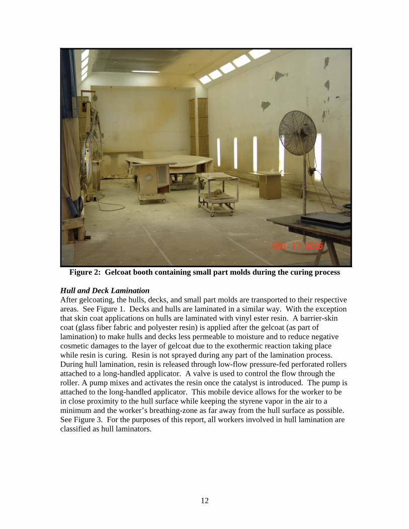
on a single part at the same time. The work load distribution for this facility is as follows: two to three employees work in hull lamination, three to five employees work in deck lamination, one to two employees work in small part lamination, and three to five employees for the internal glass unit (IGU) construction and lamination. Two to three employees also worked in the gel coat spray booth and grinding booth. The labor distribution varies depending on demand and boat production schedules. All activities which involve the use of styrene-based products were sampled during this study. While the use of closed molding at IPY is not yet widely used, IPY is exploring and expanding their use of closed-molding technologies. IPY representatives have expressed their concern regarding the cost effectiveness to manufacture in a closed-mold. IPY uses a closed-molding process known as Vacuum Infusion Molding (VIM) to make small parts such as: hatch covers and water tanks; however, the gelcoating operation required for small parts is still an open-molding process. The work load depends on the production required; two to three employees work in the closed-molding infusion area which is not separate from the glass shop. The following is a brief description discussing how FRP boats are made using both the open-molding and closed-molding processes specific to IPY’s facility. Gelcoating Before applying the gelcoat, the mold is cleaned. When needed, a wax is applied to the mold surface to ensure an easy part-mold separation. Once the mold is cleaned and waxed, it is placed in a ventilated spray booth. Gelcoat is applied to the mold to provide the smooth outer finish of the hull, deck, or small-part. When spraying large hulls, the gel coaters spray one half of the mold, and then rotate the mold longitudinally on its stand to complete the other half. Small parts are gelcoated in the same spray booth. The small parts molds are fastened to carts and moved through the plant manually. Gelcoat is sprayed by two gelcoaters (specified in this report as gelcoater, and gelcoater assistant) using atomized spray guns (Magnum Venus, Pro Gun No. 58603-3 with Air Assist VPA-100; Kent, Washington) inside a spray booth located on the northeastern side of the glass shop. See Figure 2. The gelcoating assistant also spends part of his time inside the gelcoat spray booth prepping the molds (taping edges, preparing spray gun, etc.) prior to gelcoating and moving parts left in spray-booth to their designated areas. After the parts are sprayed, they are left in the booth for approximately 30 minutes allowing the gelcoat to cure. The spray booth is not completely enclosed. The south end of the spray booth does not contain a door and was kept open during spraying. Make-up air enters the booth from the south end and is exhausted from the north end through exhaust vents (16 ft. x 44 ft. x 20 in.) located on the east and west corners of the spray booth wall. The filters in the exhaust vents are paper honeycomb with tight fiber strands. The existing spray booth exhaust fan is designed to pull 35,000 cubic feet per minute (CFM) of air. The gelcoating supervisor is seldom inside the spray booth while the gelcoating is taking place. His supervising tasks include inspection of part before and after gelcoating, documentation of material used, and organization of parts coming in and out of the gelcoat booth.
12
Figure 2: Gelcoat booth containing small part molds during the curing process
Hull and Deck Lamination After gelcoating, the hulls, decks, and small part molds are transported to their respective areas. See Figure 1. Decks and hulls are laminated in a similar way. With the exception that skin coat applications on hulls are laminated with vinyl ester resin. A barrier-skin coat (glass fiber fabric and polyester resin) is applied after the gelcoat (as part of lamination) to make hulls and decks less permeable to moisture and to reduce negative cosmetic damages to the layer of gelcoat due to the exothermic reaction taking place while resin is curing. Resin is not sprayed during any part of the lamination process. During hull lamination, resin is released through low-flow pressure-fed perforated rollers attached to a long-handled applicator. A valve is used to control the flow through the roller. A pump mixes and activates the resin once the catalyst is introduced. The pump is attached to the long-handled applicator. This mobile device allows for the worker to be in close proximity to the hull surface while keeping the styrene vapor in the air to a minimum and the worker’s breathing-zone as far away from the hull surface as possible. See Figure 3. For the purposes of this report, all workers involved in hull lamination are classified as hull laminators.

13
Figure 3: Large part laminator releasing resin using the pressure-fed perforated
rollers
Additional layers of fiberglass cloth saturated with resin are added in layers until the part attains its final desired thickness. These layers are compressed by rolling the top surface by hand. During deck lamination, a six inch metal rolling head attached to a wooden handle is used to eliminate any air pockets between the layers of resin-saturated fiberglass. Nearly twice as much resin is used to laminate hulls as is used on decks. A table displaying the resin usage for each section of the boat can be found in Table 2. A unique aspect of sailing yachts is the keel cavity that is deeper in sailboats than most other FRP boats. The keel is manufactured as part of the hull. This keel is problematic during lamination; potentially causing high exposures. Lamination and Assembly of Internal Glass Unit (IGU) The Internal Glass Unit (IGU) is the core structure of the boat. The assembly process begins with the hull, followed by the IGU, and floor timber. The IGU which is built upside down has floor timbers bonded to it on the mold. See Figure 4. Once the structure is demolded it is turned right side up and is complete. Subsequently, the structure is bonded into the hull. Each section is bonded using fiberglass fabric pieces laid out on a piece of cardboard and soaked with resin using a small brush. These pieces are then raised from the cardboard, passed to another worker, placed on the working area (laminating surface), and rolled by hand to eliminate any air pockets. Pieces of wood are inserted throughout the internal glass unit for ease of attachment of interior furniture or flooring at a later time. There are approximately six employees working on this part at one time. Since the resin application process is similar for the deck laminators and IGU

14
laminators, the air-samples taken for these two jobs were grouped together and classified as large part laminator.
Figure 4: Internal Glass Unit (IGU)
Small Parts Laminating Process Parts such as engine or hatch covers—pieces not part of the deck or hull mold—were considered small parts. Small parts molding was located in the northwest corner of the plant between the hull lamination and the gelcoat booth. These parts were constructed in a similar fashion to the decks. Molds came out of gelcoating and were moved manually on wheeled supports to the small parts area. Layers of fiberglass mats and resin were added to the mold then rolled and compressed by hand. Compared to the hull and deck molding processes, small parts production used much less glass and resin. Workers involved in the fabrication of small parts were classified as small parts laminator.

15
Table 2: Example of quantity of resin used for a 48 ft. yacht Boat Model 485 (Boat
No. 51)
lbs. of resin
Hull Skin 324.7Lamination 2 707Lamination 3 450.8Lamination 4 434.7Lamination 5 559.4Sub-total 2476.6IGU Skin 238.3Lamination 2 453.1Lamination 3 286.1Bond Wood 167.4Sub-total 1144.9Deck Skin 300.8Lamination 2 632.5Deck Bubble 1 & 2 497.8Lamination 3 460.4Sub-total 1891.5Headliner
Skin & Lam. 2 303.2Lamination 3 425Sub-total 728.2Grand-total 6241.2
Closed Molding The Vacuum Infusion Process (VIP) is a closed-molding pressure driven method that uses a vacuum to pull resin into fiberglass reinforcement plies inside the mold cavity. A single-sided mold is used with a film cover to form an air-tight seal under lower than atmospheric pressure. The inside of the mold has to be coated with a gel-coat finish similar to open-molding. The resin is pulled through the reinforcement fibers using a pressure gradient produced by an external vacuum pump. The vacuum pump is connected to the mold cavity by a series of rigid plastic tubes. Once the resin has cured, the composite part is de-molded, trimmed, and post cured. Advantages of VIP include higher fiber-content parts with fewer voids, and more dimensionally consistent products compared to open molding. Compared to open molding, this closed-molding technology may substantially reduce environmental emissions and worker exposure to styrene to a relatively uniform extent.

16
Safety Ventilation The glass shop houses the primary exhaust route in the entire building. Two sets of fans and stacks exhaust 35,000 cfm of air each and were located in the northeast and northwest booths. A Dwyer manometer was installed adjacent to each cell to monitor the pressure differentials across the filters installed at the face of the hood. When the manometer read 0.20 inches of water, the filters were changed in order to maintain the designed air flow at each hood. A heater with a fan was used for make-up air. Systems installed in this building were adjusted for weather conditions, mainly heat and humidity. The exhaust fans and booths were installed by Collins Myers located in the St. Petersburg/ Clearwater, Florida area, but the heaters and makeup air fans were installed by C&C Enterprises in Kissimmee, FL. A series of two to four industrial duty air circulator fans (Dayton, model no. 3C218G) were used throughout the glass shop to move air and aid in cooling of personnel during the hot summer months. These fans were positioned approximately 20 feet from the edge of nearly all operations. The fan specifications were: ¼ hp, 1725 revolutions per minute (RPM), 24-inch diameter, and two to three are in parallel. Hearing Conservation Program A Hearing Conservation Program is implemented at this facility. At the time of the NIOSH survey different job classifications recently had undergone hearing audits. As a result, hearing protection was required for finishers, grinders (abrasive grinding), and personnel who use portable power tools. All hearing tests (audiometric exams) were contracted out. Continuous noise was produced in the grinding booth; as a result, ear muffs (Competitor, Radians) were worn by all workers in the grinding area. The open or closed-molding process do not contribute significantly to the noise in the grinding booth. Personal Protective Equipment Safety glasses with side shields were required to be worn at all times in the facility’s manufacturing areas as company policy. All laminators, gun-operators, gelcoaters, and grinders wore Tyvek® suiting. Impermeable gloves were available for workers to use and are required when laminating. Respiratory protection was not required for any of the workers; however, it was available for workers that want to wear them. It was observed that several of the laminators wore particulate masks (models: MOLDEX 2400, NORTH 7130, and 3M 8000). All grinders wore ear plugs and ear muffs (Competitor, Radians) which attenuate noise at 26 dB when worn over the head.
17
METHODS
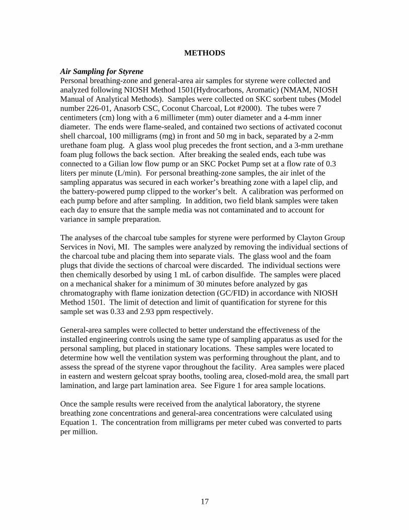
Air Sampling for Styrene Personal breathing-zone and general-area air samples for styrene were collected and analyzed following NIOSH Method 1501(Hydrocarbons, Aromatic) (NMAM, NIOSH Manual of Analytical Methods). Samples were collected on SKC sorbent tubes (Model number 226-01, Anasorb CSC, Coconut Charcoal, Lot #2000). The tubes were 7 centimeters (cm) long with a 6 millimeter (mm) outer diameter and a 4-mm inner diameter. The ends were flame-sealed, and contained two sections of activated coconut shell charcoal, 100 milligrams (mg) in front and 50 mg in back, separated by a 2-mm urethane foam plug. A glass wool plug precedes the front section, and a 3-mm urethane foam plug follows the back section. After breaking the sealed ends, each tube was connected to a Gilian low flow pump or an SKC Pocket Pump set at a flow rate of 0.3 liters per minute (L/min). For personal breathing-zone samples, the air inlet of the sampling apparatus was secured in each worker’s breathing zone with a lapel clip, and the battery-powered pump clipped to the worker’s belt. A calibration was performed on each pump before and after sampling. In addition, two field blank samples were taken each day to ensure that the sample media was not contaminated and to account for variance in sample preparation. The analyses of the charcoal tube samples for styrene were performed by Clayton Group Services in Novi, MI. The samples were analyzed by removing the individual sections of the charcoal tube and placing them into separate vials. The glass wool and the foam plugs that divide the sections of charcoal were discarded. The individual sections were then chemically desorbed by using 1 mL of carbon disulfide. The samples were placed on a mechanical shaker for a minimum of 30 minutes before analyzed by gas chromatography with flame ionization detection (GC/FID) in accordance with NIOSH Method 1501. The limit of detection and limit of quantification for styrene for this sample set was 0.33 and 2.93 ppm respectively. General-area samples were collected to better understand the effectiveness of the installed engineering controls using the same type of sampling apparatus as used for the personal sampling, but placed in stationary locations. These samples were located to determine how well the ventilation system was performing throughout the plant, and to assess the spread of the styrene vapor throughout the facility. Area samples were placed in eastern and western gelcoat spray booths, tooling area, closed-mold area, the small part lamination, and large part lamination area. See Figure 1 for area sample locations. Once the sample results were received from the analytical laboratory, the styrene breathing zone concentrations and general-area concentrations were calculated using Equation 1. The concentration from milligrams per meter cubed was converted to parts per million.

18
26.4×
=V
mC (1)
Where, C = styrene concentration, ppm m = mass of styrene per sample, µg V = volume of air sample, L Note: 4.26 is the constant used for styrene to convert from mg/m3 to ppm obtained from: NMAM (NIOSH Manual of Analytical Methods) 1501(Hydrocarbons, Aromatic) Real-time Monitoring Direct reading instruments were used to determine how exposures varied with time and to identify specific job tasks that contributed most to the workers’ exposures. Monitoring was performed using Drager Portable Gas Monitors. Specific sensors, XS EC Organic Vapor Sensors, were installed in the monitor to determine the concentration of styrene in the air. These sensors are electrochemical measuring transducers for measuring the partial pressure of gases under atmospheric conditions. They have an internal data memory (EEPROM) which includes storage of calibration data and default settings. The measuring range of these sensors is from 0 to 100 ppm with a relative sensitivity of 0 to 5 ppm. The monitors were configured to store a reading every five seconds, for approximately eight hours. The sensors were factory calibrated prior to this field survey. At the end of the sampling period, the data stored in monitors’ memories were downloaded to a laptop computer. Work activity data were combined with the real-time exposure data by determining both the exposure and the activity at any given time. A time series analysis of the real-time exposure and work activity data resulted in a model to predict worker exposures. The data obtained was used to associate events with exposures and to promote more effective and focused recommendations for controlling the styrene vapor exposures in both open and closed-mold processes. Noise Measurements In addition to measurements of plant ventilation and styrene exposure, noise exposures were also measured. Eight-hour personal and area noise level measurements were collected using five Larson-Davis 705+ and 706 Type 2 dosimeters. A total of nineteen personal measurements were collected during the survey from seven workers identified during the company’s audit as in need of a Hearing Conservation Program and who were also exposed to styrene. Each dosimeter was capable of collecting noise data in one-second increments. The dosimeters were set to simultaneously measure the OSHA PEL and the NIOSH REL. The dosimeters conformed to the American National Standards Institute (ANSI S1.25-1997) specifications.24 Dosimeters were set to “SLOW” response and A-weighting frequency filter. The equipment was calibrated by the manufacturer before the study. Field calibrations checks were conducted before measurements using a Larson-Davis CAL250 calibrator. Data from the dosimeters were downloaded to a personal computer and analyzed using the Larson-Davis 824 Utility 3.0 and BlazeTM software.

19
Statistical Analysis and Results The distributions of the all samples were checked for normality using the Shapiro-Wilk test. The results of this test suggested the data were fairly log-normally distributed; subsequently, all data were log-transformed for statistical analysis. Personal samples and area samples were analyzed separately. Geometric means, standard deviation, and 95% confidence limits are included in Table 5. General Area Samples General-area samples were grouped based on the location and distance from the styrene sources. A one-factor (location) analysis of variance model with Tukey’s multiple comparison procedures was used to test differences in exposure amongst the various area locations. Area samples were categorized into six subgroups. Results from ANOVA (p =0.0001) indicated that the exposure in the tooling area was statistically significantly lower than the exposure at any other areas at the 5% significance level. No statistically significant differences were found among areas the remainder of the areas. Personal Breathing-Zone Samples The personal breathing-zone samples were divided into twelve job categories. A two-factor (job and date) analysis of variance model with Tukey’s multiple comparison procedure was used to test the differences among the various job categories, date and interaction between job and date. At 5% significance level, no statistically significant interaction was found between job and date. Results from ANOVA (p =0.0001) indicated that the hull laminator, gelcoator, large part laminator, and small parts laminator had statistically significant higher styrene exposures than the grinding/cutting, gelcoat assistant, and tooling personnel. The styrene exposures of the gelcoat supervisor, infusion, infusion small parts supervisor, and putting and cutting personnel were also found to be statistically significant higher than the exposure of the tooling workers. For the same job, no day to day variation was found. The calculated geometric means (measure of central tendency), standard deviations, lower and upper 95% confidence limits, and sample size are shown in Table 5. Each individual result sorted by job title or area location is presented in Appendix 1. Table 5 lists each sample taken (either personal breathing-zone or general-area), job title (if personal breathing-zone sample) or specific location (if general-area sample), date, sample ID, and concentration (µg/sample and ppm).

20
Table 5: Personal and area sample statistical results for styrene vapor
Sample Type Job title
Geometric Mean [ppm]
Geometric standard deviation
Lower 95% Confidence Limit [ppm]
Upper 95% Confidence Limit [ppm] n
Area Eastern gelcoat
booth 7.92 1.39 4.66 13.45 4
Area Western gelcoat
booth 6.63 1.12 5.51 7.98 4 Area Tooling Area 1.91 1.35 1.19 3.07 4
Area Closed-mold
area 5.67 1.2 4.22 7.6 4
Area Small part
lamination area 6.46 1.27 4.39 9.51 4
Area Large part
lamination area 6.57 1.23 4.75 9.1 4 Area Grinding booth 7.06 1.23 5.07 9.84 4
Personal Gelcoat 13.65 1.22 9.97 18.68 4
Personal Gelcoat
Assistant 4.27 1.68 1.87 9.76 4
Personal Gelcoat
Supervisor 10.15 1.18 7.81 13.17 4 Personal Grinding/Cutting 5.15 1.24 4.31 6.15 8 Personal Hull Laminator 13.01 1.28 11.03 15.35 11Personal Infusion 7.34 1.39 4.33 12.45 4
Personal Infusion Small
Parts Supervisor 7.04 1.26 4.87 10.16 4
Personal Large Part Laminator 13.51 1.43 11.75 15.52 28
Personal Putty and Cutting 6.66 1.12 5.07 8.77 3
Personal Small parts laminator 11.55 1.28 9.39 14.2 8
Personal Tooling 2.58 1.96 1.68 3.96 12
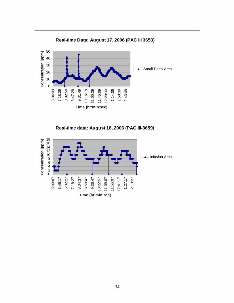
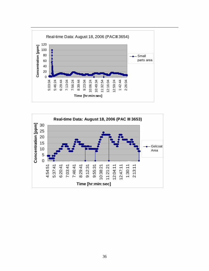
Real-time Data Direct reading instruments were used to determine how exposures vary with time and to identify specific job tasks that contribute most to the workers’ exposures. The monitors were configured to store a reading every five seconds, for approximately eight hours. Work activity data was combined with the real-time exposure data by determining both the exposure and the activity at any given time. A time series analysis of the real-time exposure and work activity data resulted in a model to predict worker exposures. The concentration versus time graphs can be found in Appendix 2. The data obtained was used to associate events with exposures and to promote more effective and focused recommendations for controlling the styrene vapor exposures in both open and closed-mold processes.

21
Noise Dosimetry Summaries of the personal exposure dosimetry measurements are shown in Table 6. The results show the time-weighted average (in dBA), dose (in percentage) of the measurements based on the NIOSH and OSHA criteria, and the maximum level for different job titles and tasks.
Table 6: Styrene concentration and noise dosimetry results for workers exposed to
both agents Job title or task Date
Styrene concentration
(ppm)
OSHA TWA Dose dBA %
NIOSH TWA Dose dBA %
Lmax dBA
Tooling 08/15/2006 08/16/2006 08/17/2006 08/18/2006
3.12 3.66 2.30 4.83
77.378.485.777.5
18.321.458.518.7
86.286.893.187.7
140.3 159.8 695.0 196.0
118.3115.6122.1119.8
Infusion/ Small parts supervisor 08/15/2006 08/16/2006 08/17/2006 08/18/2006
6.06 8.52 8.62 5.51
75.367.575.176.7
13.94.7
13.416.7
80.675.283.484.8
38.2 11.3 73.2
100.0
104.9101.8112.6109.8
Small parts laminator 08/15/2006 08/16/2006 08/18/2006
9.09 8.92 10.08
59.771.175.8
1.67.7
18.3
70.078.180.8
3.3 21.5 50.0
99.2102.4103.8
Grinding and cutting 08/15/2006 08/16/2006 08/17/2006 08/18/2006
6.56 7.26 4.07 5.72
92.691.088.689.0
151.8121.787.891.5
96.695.394.495.4
1521.0 1139.0 919.3
1144.5
127.9123.7121.8131.2
Grinding and cutting 08/17/2006 08/18/2006
4.57 4.67
90.497.0
112.7278.4
94.6100.6
973.4
3793.9 122.3127.3
Putty and Cutting 08/15/2006
7.11 89.4 97.6 94.5
947.8 114.2
Small Tanks 08/16/2006
2.18 89.9 104.6 94.4
924.4 122.6
22
DISCUSSION
The way in which yachts are manufactured at IPY is somewhat different from the more traditional recreational power boat. For example, the amounts of fiberglass and resin used per hull are significantly greater. As an example, a 51-foot boat weighs approximately 45,000 pounds. Even though sailboats typically have a lead and or iron ballast that makes up approximately 40% of its total weight, the amount of resin used per sail boat is significantly high. One would intuitively expect that the concentrations in a sailing yacht manufacturing plant would be higher due to the amount of resin used daily, but it can be inferred in this case. The data show that due to the size of the manufacturing plant, the type of ventilation currently in place, and the number of stationary fans spread throughout the facility, the styrene vapor concentration throughout the plant is practically constant. The only statistically significantly lower general-area styrene concentration was seen in the tooling area which is physically separated from the glass shop where most of the resin is used. Due to the proximity of the closed-molding and the open-molding operations, cross-contamination is likely occurring among these areas. The ventilation system installed in the glass shop is intended to be a general-ventilation system. However, due to the number of overhead doors kept open throughout the process and open doors leading to the outside, this ventilation system was not working as designed. In addition, the stationary fans throughout the facility also interfered with the design of the ventilation system. The researchers used smoke detector tubes to visually see in which direction the air was flowing. It was clear that the air was not moving in the direction in which the ventilation system was designed to move it. From observations made by the researchers and the geometric mean styrene concentration measured, it appears that the air inside the glass shop was well mixed. The individual personal breathing-zone styrene concentrations observed in the glass shop were almost all below 14 ppm. Out of the 120 total air samples collected 22 samples were above 14 ppm. Sixty-nine percent of these 22 air samples were from the large part laminators. The highest geometric mean concentrations were approximately 13.5 ppm for the following job tasks: gelcoaters, hull laminators, and large part laminators. The geometric mean concentration of 13.65 ppm for the gelcoater was likely due to the number of parts gelcoated each day and the equipment used to spray the gelcoat. The amount of time the gelcoaters spends spraying is approximately three to four hours of his eight hour work day. The remainder of the time is spent preparing other molds for gelcoating and cleaning the gelcoat booth. The real-time data indicated that the styrene concentration rises up to approximately 37.5 ppm during gelcoating of large parts and hulls. The hull laminators work the majority of their day laminating a large hull. The geometric mean concentration of the personal breathing-zone samples was 13.01 ppm. The individual styrene air-sample range for the hull laminators ranged from 9.59 to 27.47 ppm. The hull laminators unlike the gelcoaters spend all of their day working with styrene-based products (resin). The highest exposures from this group came from the same person. Worker training should be considered for hull laminators to use the proper work practices while laminating. It is important to note that the type of equipment used

23
for laminating throughout the plant is non-atomizing. No resin is sprayed during any part of the lamination process. Low-pressure-fed rollers are used to saturate the fiberglass with resin while making the large hulls. Stationary fans were placed near the process to help push the contaminated air away for the workers breathing-zone. The real-time monitor near the hull lamination area reached 33.5 ppm during the lamination of one-side of the hull. Once the hull was turned to its other side the concentration of styrene dropped to approximately 10 ppm (approximate concentration of entire glass shop). The majority of the personal-breathing zone samples were taken from the large part laminators who work on the IGUs. Twenty-eight personal-breathing zone samples were taken on workers laminating the large parts (IGUs). The geometric mean of all the large part laminators was 13.51 ppm. The mechanism used to laminate the large parts is similar to the hull lamination. Areas of the part that are hard to reach by the traditional lamination system described above are laminated by the bucket and brush system. An overhead line supplies the large part laminators with the resin which they place in a bucket. The laminators saturate the resin by placing a small rolling brush in the bucket and then transfer the resin onto the fiberglass which is laying on a piece of cardboard. The saturated fiberglass is then laid onto the boat part. Pedestal fans were also placed around the workers to aid in pushing the styrene contaminated air away form the workers’ breathing-zone. The relatively low exposures observed during the lamination process were likely due to a combination of factors such as: general-ventilation, overhead doors maintained open, lamination equipment (e.g. low flow pressure-fed rollers). No significant differences were found among the primary gelcoater, gelcoat supervisor, hull laminator, large part laminator, and small parts laminator. The exposures observed during lamination were approximately 50% lower than the ACGIH TLV and were only 20% of the NIOSH REL. Based on the area samples the ambient air concentrations were not above 8 ppm. Area sample C, tooling area, was significantly lower than the rest of the area samples. The amount of resin used in the tooling area is significantly lower than the glass shop. The geometric mean styrene concentrations measured in the tooling room were 1.91 ppm. These results are not surprising because of the amount of styrene used in this part of the building. The closed-molding process, Vacuum Infusion Process, used during the production of small parts kept the general-area styrene vapors to a geometric mean concentration of 5.67 ppm. The personal-breathing zone samples were 7.34 and 7.04 ppm for the closed molding operator and the infusion supervisor respectively. When comparing the styrene concentrations for the closed-molding operations and the open-molding operations, the concentrations are not statistically different. To take advantage of the lower styrene generation, the closed-molding operations should be conducted in a separate room to avoid cross-contamination. Regarding the small group of workers who are considered to be exposed to styrene and noise (at levels that triggered their inclusion in the company’s hearing conservation program), results indicated that the styrene exposures for this group are equal or below 10 ppm. Such low levels of styrene exposure make it difficult to determine if these
24
exposures are contributing to hearing deterioration. If any of the workers in this group develops a hearing loss that cannot be explained by their noise exposure, he or she should be referred to their physician for further examination. Noise measurement results showed large differences when calculations for time-weighted averages and dose were done using either the OSHA exchange-rate of 5 dB or NIOSH’s rate of 3 dB. The results suggest that the company might have used the 3 dB rate when deciding which workers should be included in their hearing conservation program. The 3-dB exchange rate is the method most firmly supported by scientific evidence for assessing hearing impairment as a function of noise level and duration25. The premise behind the 3-dB exchange rate is that equal amounts of sound energy will produce equal amounts of hearing impairment regardless of how the sound energy is distributed in time. These workers whose noise exposure measurements were obtained are already in the company’s hearing conservation program. Their noise exposures are quite different by job title and task, indicating different needs regarding hearing loss prevention. For instance, the workers involved in grinding and cutting need to wear double hearing protection; the company indicated that they are already doing so. The attenuation of this combined protection should be carefully evaluated. Another approach to be considered should be the use of administrative or engineering controls, in this case, the purchase of quieter grinders. Workers involved in the other tasks measured do not seem to need as much attenuation. In their case, the concern should be to avoid over-attenuation, because it might discouraged the workers from wearing the hearing protection. Details on how to select appropriate hearing protection and on other phases of an effective hearing conservation program can be found in the NIOSH criteria document25 or part (a) of the OSHA noise exposure standard (29 CFR 1910.95).21

25
CONCLUSIONS AND RECOMMENDATIONS According to an environmental health and safety (EHS) representative, the highest styrene exposure zones occur while making the hulls, decks, and internal glass units (IGU). Due to the shape and configuration of sailing yachts, it is believed that the worker’s breathing-zone is near the laminating surface more when compared to traditional recreational-boat manufacturing. The lamination and rolling steps in boat manufacturing are historically known for having the highest styrene vapor in air. The data taken during this study align with the statements made above. Simple precautions like the three directed fans in parallel can be taken to ensure a low styrene-vapor environment. However, it is up to the plant management to ensure that the ventilation system is properly balanced. Another styrene exposure assessment should be conducted during the winter season. The open overhead doors which allow for styrene vapors to escape would likely be closed during the winter. The styrene concentrations would likely be higher in the winter. Exhaust ventilation, low styrene-content resin, non-atomizing spray equipment, and personal protective equipment have historically been recommended to limit styrene vapor exposures to workers. The ventilation system currently in place should be rebalanced because the air in the glass shop is not moving as intended. There are too many factors or sources inside the glass shop that are causing the entire glass shop to be well mixed. The styrene vapors throughout the plant contaminate the workers who are involved in the closed-molding operations. Contributing factors include excessive stationary fans and overhead doors. The developments in specific closed-molding technologies, however, may also provide protection by reducing process emissions of styrene, and, in turn, the concentration of styrene in the workers’ breathing zones. It was observed that the area where the closed molding Vacuum Infusion was taking place had the same concentration of styrene in the air as the open-molding operations. It is recommended that this process be performed in a distinct place away from the open-molding operations. It was observed that several employees wore particulate respirators that consisted of a Moldex 2400, North 7130, or 3M 8000. The Moldex 2400 protects against both particulates and organic vapors. The other two types of respirators are N-95 particulate respirators and do not protect against organic vapors. If a respirator is provided for an employee it should have the ability to remove organic vapors (i.e., styrene vapors). If particulates are of concern, the respirator should be able to remove both the particulate and the organic vapors. In accordance with 29 CFR 1910.134, if the employer determines that any voluntary respirator use is permissible, the employer shall provide the respirator users with the information contained in Appendix D of 29 CFR 1910.13426. Since styrene can cause dermatitis and has a skin notation in the TLV, there is a potential for workers to be exposed to styrene by absorption through the skin. Proper gloves that protect workers against styrene contact should be worn by all employees all of the time.
26
REFERENCES 1 United States. Bureau of the Census: Statistics of U.S. Businesses (SUSB). [http://www.census.gov] data for 2004. Data accessed: 2006. 2 Environmental Protection Agency (EPA): National Emission Standards for Hazardous Air Pollutants for Boat Manufacturing; Proposed Rule, Part II. 40 CRF Part 63, July 14, 2000. 3 Mutti A, Mazzucchi A, Rustichelli P, Frigeri G, Arfini G, Franchini I: Exposure-effect and exposure-response relationships between occupational exposure to styrene and neuropsychological functions. American Journal of Industrial Medicine. 5:275-286 (1984). 4 Fung F. Clark RF: Styrene-induced peripheral neuropathy. Journal of Toxicology - Clinical Toxicology. 37(1):91-7 (1999). 5 Tsai SY. Chen JD. Neurobehavioral effects of occupational exposure to low-level styrene. Neurotoxicology & Teratology. 18(4):463-9, (1996). 6 Gong, Y. Y., R. Kishi, et al: Relation between colour vision loss and occupational styrene exposure level. Occupational & Environmental Medicine 59(12): 824-9 (2002). 7 Triebig, G., T. Stark, et al: Intervention study on acquired color vision deficiencies in styrene-exposed workers. Journal of Occupational & Environmental Medicine 43(5): 494-500 (2001). 8 Minamoto K. Nagano M. Inaoka T. Futatsuka M: Occupational dermatoses among fiberglass-reinforced plastics factory workers. Contact Dermatitis. 46(6):339-47, (2002). 9 American Conference of Governmental Industrial Hygienists (ACGIH): Documentation of Threshold Limit Values and Biological Exposure Indices: TLV for Styrene. American Conference of Governmental Industrial Hygienists. Cincinnati, OH, (2001). 10 Campo P, Lataye R, Loquet G, Bonnet P: Styrene-induced hearing loss: a membrane insult. Hearing Research 154(1-2):170-80 (2001).
11 Lataye R. Campo P. Pouyatos B. Cossec B. Blachere V. Morel G: Solvent ototoxicity in the rat and guinea pig. Neurotoxicology & Teratology. 25(1):39-50 (2003).
12 Morata, T. C., A. C. Johnson, et al: “Audiometric findings in workers exposed to low levels of styrene and noise." Journal of Occupational & Environmental Medicine 44(9): 806-14 (2002).

27
13 Sliwinska-Kowalska M, Zamyslowska-Smytke E, Szymczak W, Kotylo P, Fiszer M, Wesolowski W, Pawlaczyk-Luszczynska M: Ototoxic effects of occupational exposure to styrene and co-exposure to styrene and noise. Journal of Occupational and Environmental Medicine 45 (1): 15-24 (2003). 14 Makitie AA. Pirvola U. Pyykko I. Sakakibara H. Riihimaki V. Ylikoski J: The ototoxic interaction of styrene and noise. Hearing Research. 179(1-2):9-20 (2003).
15 Lataye R. Campo P. Loquet G: Combined effects of noise and styrene exposure on hearing function in the rat. Hearing Research. 139(1-2):86-96 (2000).
16 Occupational Safety and Health Administration. Code of Federal Regulations. 29 CFR 1910. “Occupational Safety and Health Standards.” U.S. Government Printing Office, Office of the Federal Register. Washington, D.C., (2002) 17 National Institute for Occupational Safety and Health. “Recommendations for occupational safety and health: compendium of policy documents and statements.” U.S. Department of Health and Human Services, Public Health Service, Centers for Disease Control and Prevention, National Institute for Occupational Safety and Health, DHHS (NIOSH) Publication No. 92B100 (1992) 18 American Conference of Governmental Industrial Hygienists (ACGIH): TLVs® and BEIs® Threshold Limit Values for Chemical Substances and Physical Agents & Biological Exposure Indices. American Conference of Governmental Industrial Hygienists. Cincinnati, OH, (2004). 19 National Institute for Occupational Safety and Health (NIOSH): NIOSH Pocket Guide to Chemical Hazards and Other Databases – REL for Styrene. DHHS (NIOSH) Pub. No. 2004-103 (2004). 20 Occupational Safety and Health Administration: Code of Federal Regulations. 29
CFR 1910.95. “Occupational Exposure to Noise”. U.S. Government Printing Office, Office of the Federal Register. Washington, D.C., (1992).
21 National Institute for Occupational Safety and Health: Criteria for a recommended standard — Occupational noise exposure (revised criteria 1998), Cincinnati, OH: U.S. Department of Health and Human Services, Public Health Service, Centers for Disease Control and Prevention, National Institute for Occupational Safety and Health, DHHS (NIOSH) Publication No. 98-126 (1998).
22 U.S. Environmental Protection Agency (EPA): [2001]. Fact Sheet: Final regulation to reduce toxic air pollutant emissions from the boat manufacturing industry. August 14, 2001.

28
23 Office of Public Affairs (Washington D.C.) [1996]. OSHA announces that styrene industry has adopted voluntary compliance program to improve worker protection. News Release, 01 March 1996. Washington, DC. http://www.acmanet.org/ga/osha_styrene_agreement_docs_1996.pdf. 24 American National Standards Institute. Specification for Personal Noise Dosimeters. ANSI S1.25-1991 (R1997), New York, New York.
25 National Institute for Occupational Safety and Health (NIOSH Criteria for a Recommended Standard: Occupational Exposure to Noise. (Rev Criteria) Cincinnati, OH: 1998; Publication No. 98-126 26 Occupational Safety and Health Administration: Code of Federal Regulations. 29 CFR 1910.134 App D. “(Mandatory) Information for Employees Using Respirators When not Required Under Standard”. U.S. Government Printing Office, Office of Federal Register. Washington, D.C., (1998).

29
APPENDIX 1
Job Title Date Sample ID
Result (ug/Sample)
Concentration [ppm]
Noise Dosimeter No.
Infusion 8/15/2006 101 490 6.32 Infusion Small Parts Supervisor 8/15/2006 102 380 6.06 1705 Area D 8/15/2006 103 330 4.46 Small Parts Laminator 8/15/2006 104 480 10.63 Blank 8/15/2006 105 0 0.00 Blank 8/15/2006 106 0 0.00 Small Parts Laminator 8/15/2006 107 730 9.09 1706 Infusion Small Parts Supervisor 8/16/2006 109 320 8.52 1704 Hull Laminator 8/16/2006 110 730 11.84 Hull Laminator 8/15/2006 111 830 11.11 Small Tanks 8/15/2006 112 370 5.07 Hull Laminator 8/15/2006 113 650 10.89 Large Part Laminator 8/15/2006 114 1200 15.94 Area F 8/15/2006 115 370 4.97 Hull Laminator 8/15/2006 116 810 11.11 Blank 8/15/2006 118 0 0.00 Putty and Cutting 8/15/2006 119 410 7.11 17460 Blank 8/15/2006 120 0 0.00 Area A 8/15/2006 121 390 4.89 Gelcoat Supervisor 8/15/2006 122 580 10.50 Tooling 8/15/2006 123 86 1.35 Area E 8/15/2006 124 360 4.54 Gelcoat 8/15/2006 125 920 12.88 Tooling 8/15/2006 126 230 4.04 Tooling 8/15/2006 127 210 3.12 1703 Gelcoat Assistant 8/15/2006 128 290 4.85 Area C 8/15/2006 130 220 2.80 Large Part Laminator 8/15/2006 131 710 12.61 Grinding/Cutting 8/15/2006 132 410 6.56 1704 Large Part Laminator 8/15/2006 133 1100 19.83 Area B 8/15/2006 135 520 6.69 Large Part Laminator 8/15/2006 136 750 12.52 Area G 8/15/2006 137 420 5.52 Large Part Laminator 8/15/2006 138 640 8.52

30
Large Part Laminator 8/15/2006 139 1000 14.10 Large Part Laminator 8/15/2006 140 1200 19.81 Area C 8/16/2006 141 120 1.44 Gelcoat Assistant 8/16/2006 142 130 2.02 Tooling 8/16/2006 143 56 1.00 Tooling 8/16/2006 144 280 3.66 17460 Tooling 8/16/2006 145 500 6.58 Infusion 8/16/2006 146 890 11.62 Area E 8/16/2006 147 570 6.86 Gelcoat 8/16/2006 148 1200 17.55 Small Parts Laminator 8/16/2006 149 630 9.92 Area A 8/16/2006 150 770 9.70 Area D 8/16/2006 151 460 6.84 Small Parts Laminator 8/16/2006 152 730 8.92 1706 Large Part Laminator 8/16/2006 153 1400 22.26 Large Part Laminator 8/16/2006 154 1500 23.48 Gelcoat Supervisor 8/16/2006 155 500 7.97 Large Part Laminator 8/16/2006 156 1300 16.66 Large Part Laminator 8/16/2006 157 1600 20.69 Area B 8/16/2006 158 540 7.23 Large Part Laminator 8/16/2006 159 1000 15.66 Grinding/Cutting 8/16/2006 160 390 5.07 Large Part Laminator 8/16/2006 161 350 5.18 Area F 8/16/2006 162 510 6.44 Area D 8/17/2006 163 420 5.45 Area G 8/16/2006 164 720 9.18 Hull Laminator 8/16/2006 165 790 9.89 Small Tanks 8/16/2006 166 150 2.18 1705 Gelcoat Supervisor 8/17/2006 167 740 11.37 Putty and Cutting 8/16/2006 168 400 5.87 Large Part Laminator 8/16/2006 169 2000 26.12 Grinding/Cutting 8/16/2006 170 470 7.26 1703 Tooling 8/17/2006 171 240 3.52 Infusion 8/17/2006 172 600 7.37 Area A 8/17/2006 173 770 10.04 Blank 8/16/2006 174 0 0.00 Area E 8/17/2006 175 580 7.90
31
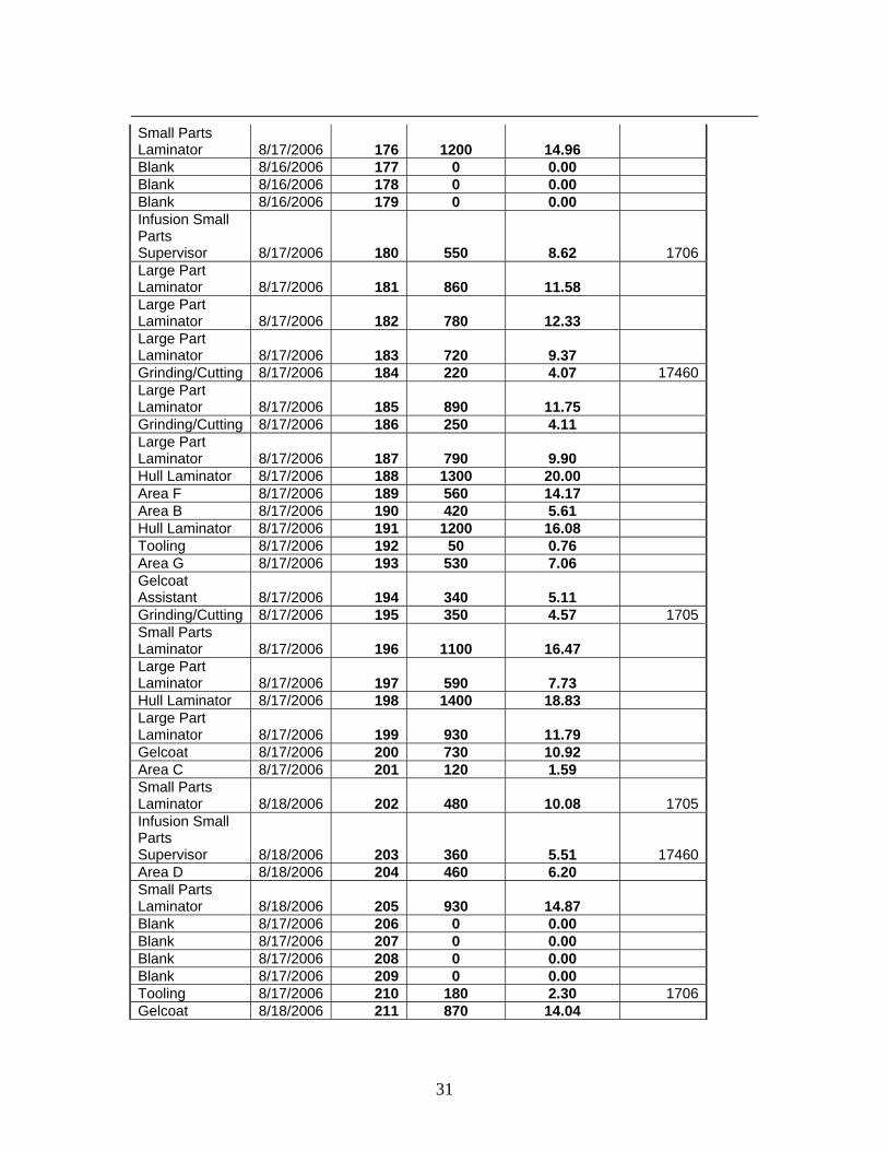
Small Parts Laminator 8/17/2006 176 1200 14.96 Blank 8/16/2006 177 0 0.00 Blank 8/16/2006 178 0 0.00 Blank 8/16/2006 179 0 0.00 Infusion Small Parts Supervisor 8/17/2006 180 550 8.62 1706 Large Part Laminator 8/17/2006 181 860 11.58 Large Part Laminator 8/17/2006 182 780 12.33 Large Part Laminator 8/17/2006 183 720 9.37 Grinding/Cutting 8/17/2006 184 220 4.07 17460 Large Part Laminator 8/17/2006 185 890 11.75 Grinding/Cutting 8/17/2006 186 250 4.11 Large Part Laminator 8/17/2006 187 790 9.90 Hull Laminator 8/17/2006 188 1300 20.00 Area F 8/17/2006 189 560 14.17 Area B 8/17/2006 190 420 5.61 Hull Laminator 8/17/2006 191 1200 16.08 Tooling 8/17/2006 192 50 0.76 Area G 8/17/2006 193 530 7.06 Gelcoat Assistant 8/17/2006 194 340 5.11 Grinding/Cutting 8/17/2006 195 350 4.57 1705 Small Parts Laminator 8/17/2006 196 1100 16.47 Large Part Laminator 8/17/2006 197 590 7.73 Hull Laminator 8/17/2006 198 1400 18.83 Large Part Laminator 8/17/2006 199 930 11.79 Gelcoat 8/17/2006 200 730 10.92 Area C 8/17/2006 201 120 1.59 Small Parts Laminator 8/18/2006 202 480 10.08 1705 Infusion Small Parts Supervisor 8/18/2006 203 360 5.51 17460 Area D 8/18/2006 204 460 6.20 Small Parts Laminator 8/18/2006 205 930 14.87 Blank 8/17/2006 206 0 0.00 Blank 8/17/2006 207 0 0.00 Blank 8/17/2006 208 0 0.00 Blank 8/17/2006 209 0 0.00 Tooling 8/17/2006 210 180 2.30 1706 Gelcoat 8/18/2006 211 870 14.04

32
Gelcoat Supervisor 8/18/2006 212 730 11.14 Tooling 8/18/2006 213 320 4.26 Area E 8/18/2006 214 580 7.09 Tooling 8/18/2006 215 110 1.70 Tooling 8/18/2006 216 370 4.83 1704 Gelcoat Assistant 8/18/2006 217 430 6.67 Area C 8/18/2006 218 170 2.08 Area A 8/18/2006 219 690 8.27 Infusion 8/18/2006 220 430 5.37 Grinding/Cutting 8/18/2006 221 370 4.67 1703 Hull Laminator 8/18/2006 222 920 11.75 Hull Laminator 8/18/2006 223 1200 27.47 Large Part Laminator 8/18/2006 224 1200 15.65 Area G 8/18/2006 225 410 6.97 Hull Laminator 8/18/2006 226 820 10.62 Grinding/Cutting 8/18/2006 227 380 5.72 1705 Large Part Laminator 8/18/2006 228 1100 13.67 Large Part Laminator 8/18/2006 229 900 11.66 Large Part Laminator 8/18/2006 230 900 14.54 Area B 8/18/2006 231 640 7.12 Large Part Laminator 8/18/2006 232 950 12.28 Blank 8/18/2006 233 0 0.00 Large Part Laminator 8/18/2006 234 770 10.17 Blank 8/18/2006 235 0 0.00 Blank 8/18/2006 236 0 0.00 Area F 8/18/2006 237 570 7.45 Large Part Laminator 8/18/2006 238 1000 15.56 Putty and Cutting 8/18/2006 239 410 7.10 Blank 8/18/2006 240 0 0.00

33
APPENDIX 2
Real-time Data: August 17, 2006 (PAC III- 0359)
05
10152025303540
6:33
:01
7:14
:11
7:55
:21
8:36
:21
9:17
:21
9:58
:31
10:3
9:31
11:2
0:41
12:0
1:51
12:4
3:01
1:24
:11
2:05
:21
2:46
:31
Time [hr:min:sec]
Conc
entra
tion
[ppm
]
Gelcoat Area
Real-time Area: August 17, 2006 (PAC III 3656)
0
5
10
15
20
6:31
:02
7:10
:52
7:50
:32
8:30
:22
9:10
:12
9:49
:52
10:2
9:42
11:0
9:22
11:4
9:12
12:2
9:02
1:08
:52
1:48
:42
2:28
:32
3:08
:22
Time [hr:min:sec]
Con
cent
ratio
n [p
pm]
InfusionArea
34
Real-time Data: August 17, 2006 (PAC III 3653)
0
10
20
30
40
506:
34:0
9
7:18
:39
8:02
:59
8:47
:29
9:31
:49
10:1
6:19
11:0
0:39
11:4
5:09
12:2
9:39
1:14
:09
1:58
:39
2:43
:09
Time [hr:min:sec]
Conc
entra
tion
[ppm
]
Small Parts Area
Real-time data: August 18, 2006 (PAC III-3659)
02468
1012141618
5:00
:07
5:46
:17
6:32
:27
7:18
:27
8:04
:37
8:50
:47
9:36
:47
10:2
2:57
11:0
9:07
11:5
5:07
12:4
1:17
1:27
:17
2:13
:27
Time [hr:min:sec]
Conc
entra
tion
[ppm
]
Infusion Area

35
Real-time data: August 18, 2006 (PACIII 3658)
05
101520253035
5:42
:09
6:26
:49
7:11
:29
7:56
:09
8:40
:49
9:25
:29
10:1
0:09
10:5
4:39
11:3
9:19
12:2
3:49
1:08
:29
1:53
:09
2:37
:49
Time [hr:min:sec]
Conc
entra
tion
[ppm
]
Hull Lamination
Real-time data: August 18, 2006 (PAC III 3656)
0
5
10
15
20
25
5:31
:03
6:15
:43
7:00
:23
7:45
:03
8:29
:43
9:14
:23
9:59
:03
10:4
3:33
11:2
8:13
12:1
2:43
12:5
7:23
1:42
:03
2:26
:43
Time [hr:min:sec]
Conc
entra
tion
[ppm
]
Center of IGUlamination
36
Real-time Data: August 18, 2006 (PACIII 3654)
0204060
80100120
5:03
:04
5:46
:24
6:29
:44
7:13
:04
7:56
:24
8:39
:44
9:23
:04
10:0
6:24
10:4
9:34
11:3
2:54
12:1
6:04
12:5
9:24
1:42
:44
2:26
:04
Time [hr:min:sec]
Conc
entra
tion
[ppm
]
Smallparts area
Real-time Data: August 18, 2006 (PAC III 3653)
05
1015202530
4:54
:51
5:37
:41
6:20
:41
7:03
:41
7:46
:41
8:29
:41
9:12
:31
9:55
:31
10:3
8:21
11:2
1:21
12:0
4:11
12:4
7:11
1:30
:11
2:13
:11
Time [hr:min:sec]
Con
cent
ratio
n [p
pm]
GelcoatArea