in - · pdf fileatanab e (1992) compared the p erformance of the middle v essel batc h...
TRANSCRIPT

Integrated Design, Operation and Control of
Batch Extractive Distillation with a Middle Vessel
E. K. Hilmen and S. Skogestad�
Center for Process Systems Engineering, Department of Chemical Engineering,
Norwegian University of Science and Technology, N-7034 Trondheim, Norway
M. F. Doherty and M. F. Malone
Process Design and Control Center, Department of Chemical Engineering,
University of Massachusetts - Amherst, MA 01003, U.S.A.
Prepared for presentation at the 1997 Annual Meeting:
Los Angeles, CA, Nov. 16-21Design and Analysis. Paper No. 201h
Abstract
This paper focuses on the use of batch extractive distillation for separating homogeneousminimum-boiling azeotropic mixtures, where the extractive agent is a high-boiling, misciblezeotropic component. The e�ect of column design on the operation is evaluated and a controlstructure for the batch extractive middle vessel distillation is proposed.
In extractive distillation, the non-volatile solvent is fed continuously to the top of thecolumn in order to be present on all the plates during the separation. In a conventionalbatch column con�guration, this semi-continuous operation has two main disadvantages dueto accumulation of the extractive agent: (1) �lling of the reboiler, and (2) degradation of thecomposition pro�le in the column. The �rst may cause operational problems and the latterdecreases the e�ciency of the separation.
One way to overcome these problems is to use a middle vessel column. The middle vesselcolumn arrangement consists of two column sections, a batch recti�er and a batch stripper,connected by a middle vessel. The azeotropic mixture to be separated is charged to themiddle vessel and the extractive solvent is fed to the head of the rectifying section. Thiscon�guration allows for simultaneous removal of product(s) and recovery of the extractiveagent. In addition, the volume of the middle vessel can be kept constant or even decreasingwith time. Thus, high separation e�ciency can be achieved since the sharpness of the columncomposition pro�le is maintained during the distillation run. Furthermore, the middle vesselimplementation is potentially more energy e�cient than conventional distillation due to thecombination of a rectifying-extraction section and a stripping section in one column. Batchextractive distillation with a middle vessel is closely related to the well-known continuousextractive distillation except that the separation is performed in one rather than in twocolumns, which may imply capital savings for the batch implementation.
We propose a novel control con�guration for the batch extractive middle vessel distillationwhere the liquid ow from the middle vessel is manipulated to control the temperature in thestripping section, achieving a desired purity of the extractive agent. This indirectly adjusts
�Author to whom correspondence should be addressed: email: [email protected], phone: +47-7359-4154,fax: +47-7359-4080
1

the vessel holdup and there is no need for level control. The extractive agent feed is used tocontrol the purity of the distillate and the re ux is held constant below its maximum value.
1 Introduction
The work presented in this paper is connected to an industrial project on solvent recovery inpharmaceutical production and �ne- and specialty chemical industries. Batch distillation ofnonideal liquid mixtures is widely used and the most important separation operation in small-scale production with need for exibility due to changing product demands. A multicomponentmixture can be separated into a number of product fractions in a single batch column whereas,in continuous distillation several columns are required. A batch distillation column can alsohandle a wider range of feed compositions, relative volatilities and product speci�cations. Thesame column can therefore be used for a number of di�erent separation tasks. However, waste-solvents from the bulk synthesis operations in pharmaceutical- and specialty chemical productionoften form homogeneous azeotropic (hereafter called homoazeotropic) mixtures which may beimpossible to separate into pure components by ordinary batch distillation. The puri�cationof such solvent streams typically involves dehydration of low-boiling organic solvents formingminimum-boiling homoazeotropic mixtures with water. The most common method to separatesuch mixtures is by means of extractive distillation.
While extractive distillation in continuous columns is extensively described in the literature (seefor example Van Winkle (1967), Perry and Chilton (1973), Doherty and Knapp (1993)), theknowledge on operation of extractive distillation in batch columns is limited. Batch extractivedistillation is to the authors knowledge not used industrially even though there exist a great needfor this technology in the pharmaceutical- and specialty chemical industries that typically bene�tfrom batch operation. This is probably due to its potential complexity of operation, and loss of exibility which again is one of the main reasons the batch column is chosen. In addition, thereis a need for experimental veri�cation and practical implementation of the di�erent operatingpolicies for the process.
This paper focuses on the use of batch extractive distillation for separating homogeneous minimum-boiling azeotropic mixtures, where the extractive agent is a high-boiling, miscible zeotropiccomponent. The e�ect of two principally di�erent batch column designs on the operation isevaluated and a control structure for the batch extractive middle vessel distillation is proposed.The inherent dynamics of batch distillation operation introduces new aspects to the extractivedistillation process as compared to continuous operation.
Other publications on batch extractive distillation
Kogan (1971) describes a laboratory unit of extractive batch distillation and points out thedisadvantage of increasing dilution of the still pot by the extractive solvent during the operation.In a series of papers, Yatim and Lang et al. (1993, 1994, 1995) gives experimental as well assimulation results on the operation of extractive distillation in the conventional batch columncon�guration (i.e. batch recti�er). In the paper by D�ussel and Stichlmair (1995), the extractivedistillation scheme for a batch recti�er is outlined.
Safrit et al. (1995, 1997) studied the batch extractive middle vessel column for separation of abinary azeotropic mixture using an extractive agent which is continuously removed and recycled.
2
They compared the separation performance of this column with a conventional continuous ex-tractive distillation column. The middle vessel column showed better performance in regard toenergy consumption. The study also showed that the performance of the separation is sensitiveto the entrainer owrate and to the switching times between fractions in the batch operation.They propose a way to 'steer' the middle vessel composition by balancing the two oppositedirected e�ects of product removal to achieve a desired purity in distillate and bottoms product.
Publications on the middle vessel batch distillation con�guration
There are two principally di�erent modes, or uses, for the batch distillation with a middle vessel:(1) separation of binary mixtures, and (2) separation of ternary- or multicomponent mixtures. Inboth cases the mixture is initially fed to the middle vessel (or distributed along the column). Inthe �rst mode, the binary separation is performed simultaneously in the batch recti�er and thebatch stripper taking out the light component as distillate and the heavy component as bottomsproduct. The volume of the middle vessel decreases during the operation. In the second mode,separating for example an ideal ternary mixture, intermediate-boiling component of increasingpurity can be accumulated in the middle vessel and collected as a pure product at the end ofthe distillation run.
The idea of using the middle vessel batch distillation column con�guration for separating mul-ticomponent mixtures is not new. In the textbook by Robinson and Gilliland (1950), thiscombined operation of a batch recti�er and a batch stripper is mentioned for accumulating anintermediate component in the middle vessel while removing light- and heavy impurities. Bor-tolini and Guarise (1970) was to the authors knowledge the �rst to present an analysis of thiscolumn con�guration for separating ideal binary mixtures. In 1976, Devyatikh and Churbanovdescribed separation of ternary mixtures by the middle vessel batch distillation con�guration(as quoted by Davydian, Kiva, Meski and Morari (1994)).
Several authors have presented comparative studies between conventional batch distillationcolumns and the middle vessel con�guration for ideal binary and ternary mixtures. Hasebe,Abdul Aziz, Hashimoto and Watanabe (1992) compared the performance of the middle vesselbatch distillation column, denoted complex batch distillation column, for separating ideal ternarymixtures with conventional batch distillation. The middle vessel batch distillation column wasshown to have the best separation performance. The idea of using a middle vessel was laterextended to a multi-vessel batch column con�guration with total re ux operation for separat-ing more than three components (Hasebe, Kurooka and Hashimoto 1995). They denote this amulti-e�ect batch distillation system. Skogestad, Wittgens, S�rensen and Litto (1995) proposeda generalization of this structure along with novel feedback control strategy for such total re uxmulti-vessel batch distillation columns.
In a series papers, Davydian, Kiva and Platonov (1991a, 1991b, 1992a, 1992b, 1993) presentedthe use of batch distillation columns with a middle vessel for separating binary and ternarymixtures (parallel to the work by Hasebe et al. (1992)). Based on this work, Davydian et al.(1994) present an analytical analysis of the dynamic behavior of the middle vessel batch distilla-tion column for separating multicomponent mixtures. The authors point out several advantagesand new opportunities for the middle vessel con�guration as compared to conventional batchdistillation column designs (Davydian et al. 1994):
� A binary mixture can be separated into pure components under �nite [constant]reboil and re ux ratio and, in some cases, faster than using conventional types
3

of batch distillations.
� For ternary separation one can always choose parameters, like re ux and reboilratios, such that the composition in the middle vessel tends to either one of thethree components [the intermediate-boiling component for ideal mixtures].
� A multicomponent mixture can be separated into heavy, intermediate and lightfractions simultaneously, so one can remove light and heavy impurities from themixture.
Meski and Morari (1995) analyzed the behavior of the middle vessel con�guration for binaryand ternary mixtures at total re ux and minimum re ux conditions. They con�rm the previousresults by Hasebe et al. (1992) that the middle vessel batch distillation column always performbetter than the conventional design. They also conclude that it is optimal to operate the columnunder constant re ux- and reboil ratios in the case of binary separation, keeping the compositionin the middle vessel constant equal to the initial feed composition with gradual decreasing holdupof the middle vessel. Barolo and Guarise et al. (1996a, 1996b) address issues on design andoperation of the batch distillation column with a middle vessel for separating ternary mixtures,partly based on experience from operating a continuous distillation pilot plant in a batch mode.
2 Basic Concepts
Most distillation methods for separating homoazeotropic mixtures rely on the addition of spe-cially chosen chemicals to facilitate separation (Doherty and Knapp 1993). These separationagents, also called entrainers, can be miscible, partly miscible or imiscible, zeotropic or azeotropic(introducing new azeotropes to the system). The distillation techniques to be utilized depends onthe resulting vapor- liquid equilibrium behavior of the basic azeotropic mixture with separatingagent.
2.1 Extractive Distillation
Benedict and Rubin (1945) gives the following de�nition of extractive distillation:
Distillation in the presence of a substance which is relatively non-volatile comparedto the components to be separated and which, therefore, is charged continuously near
the top of the distilling column so that an appreciable concentration is maintained onall plates of the column.
In this paper we focus on extractive distillation for separation of binary minimum-boiling ho-moazeotropic mixtures. Extractive distillation may be used for separation of multicomponentmixtures as well. Phase equilibrium diagrams like simple distillation residue curve maps (RCMs)and information about the univolatility lines provides a graphical tool to evaluate how the sepa-rating agent modi�es the volatilities of the azeotrope components in the mixture. Knowing theresidue curve map for the resulting ternary system to be separated is su�cient to determine if agiven separation objective is feasible, but not whether the objective can be achieved economically(Doherty and Knapp 1993). An overview of the main conditions that a candidate extractivesolvent must satisfy in order to make the separation feasible are given in the following1.
1Several authors have outlined solvent selection criteria for extractive distillation (Berg 1969, Doherty andKnapp 1993): 1. Higher boiling temperature than the components to be separated �TS�1;2 > 30oC, 2. Sub-
4

First condition:
The mixture of the binary minimi-boiling azeotrope and solvent should form aVLE diagramof the type shown in �gure 1.
Residue Curves Map
METHANOL0.1 0.2 0.3 0.4 0.5 0.6 0.7 0.8 0.9
0.1
0.2
0.3
0.4
0.5
0.6
0.7
0.8
0.90.1
0.2
0.3
0.4
0.5
0.6
0.7
0.8
0.9
AC
ETO
NE
ACETONE
METHANOL
WA
TER
WATER
α = 112univolatility line
12
> 1α 12
α < 1
2Solvent(SN)
(SA)1
(SA)
(UN)12Az
Figure 1: Residue curve map for a ternary azeotropic mixture of components 1, 2 and solventthat is promising for extractive distillation. Az12 denotes a binary minimum-boiling azeotropebetween 1 and 2. The change in volatility order between 1 and 2 is represented by the uni-volatility line �12 = 1.
Second condition:
The solvent must cause a substantial change in the relative volatility between the azeotropeconstituents. A measure of the solvent selectivity is the relative volatility between theazeotrope constituents at in�nite dilution in the solvent: �112 (S) > 2:0 (typically).
Third condition:
The solvent must have higher boiling-point than the azeotrope constituents, �TS�1;2 >300C, and preferably large relative volatility between the solvent and the distillate product.
Rule of thumb: The larger boiling-point di�erence between the agent and distillate, theless number of trays needed in rectifying section (usually �TS�1;2 = 50� 1500C).
The main feature of the diagram shown in �gure 1 is the shape of the simple distillation residuecurves near the stable node (SN) (the solvent must be a stable node). The presence of anunivolatility line deforms the residue curves according to the solvent selectivity (S-shaped residuecurves). The minimum-boiling azeotrope is an unstable node (UN) in the whole compositionspace (triangle). The pure components 1 and 2 are saddle points (SA), but the pure component
stantial change in relative volatility when present at moderate compositions, 3. Low latent heat since part of theagent stream will be vaporized in the reboiler, 4. Thermally stable, 5. Nonreactive with the other componentsin the mixture, 6. Available and inexpensive, 7. Nontoxic, and 8. Easily separable from the component with itassociates.
5
1 is an unstable node of the binary edge between 1 and solvent. The univolatility line, locuswhere �12 = 1 in �gure 1, extends from the azeotrope to the binary edge between the solventand component 1. Thus, component 1 will be recovered in the distillate since it is the mostvolatile component in the rectifying section (Laroche, Bekiaris, Andersen and Morari 1993).
In continuous extractive distillation columns, component 2 will be taken out as bottoms producttogether with the solvent. This scheme requires a direct sequence of two columns, one extractivedistillation column and one column to separate component 2 from the solvent (for the systemgiven in �gure 1).
Composition pro�le in extractive distillation columns
Extractive distillation obtain a saddle as distillate product and the process works 'against' thesimple distillation residue curves. This is the main characteristic of the extractive distillationprocess. Knapp and Doherty (1994) and Bauer and Stichlmair (1995) presents compositionpro�les in continuous extractive distillation columns for the acetone-methanol-water mixtureand geometric representation of the continuous extractive distillation process is given in a seriesof papers (Levy and Doherty 1986, Knapp and Doherty 1990, Knapp and Doherty 1994).
Residue Curves Map
METHANOL0.1 0.2 0.3 0.4 0.5 0.6 0.7 0.8 0.9
0.1
0.2
0.3
0.4
0.5
0.6
0.7
0.8
0.90.1
0.2
0.3
0.4
0.5
0.6
0.7
0.8
0.9
AC
ETO
NE
ACETONE
METHANOL
WA
TER
WATER
0F
B
D
FT
mixing linemass balance linecolumn composition profile
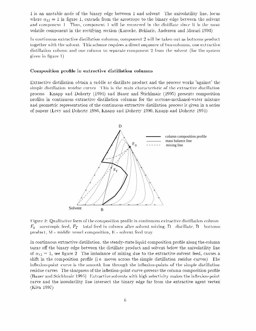
Solvent
Figure 2: Qualitative form of the composition pro�le in continuous extractive distillation column.F0 - azeotropic feed, FT - total feed in column after solvent mixing, D - distillate, B - bottomsproduct, M - middle vessel composition, E - solvent feed tray.
In continuous extractive distillation, the steady-state liquid composition pro�le along the columnturns o� the binary edge between the distillate product and solvent below the univolatility lineof �12 = 1, see �gure 2. The imbalance of mixing due to the extractive solvent feed, causes ashift in the composition pro�le (i.e. moves across the simple distillation residue curves). Thein exion-point curve is the smooth line through the in exion-points of the simple distillationresidue curves. The sharpness of the in exion-point curve governs the column composition pro�le(Bauer and Stichlmair 1995). Extractive solvents with high selectivity makes the in exion-pointcurve and the isovolatility line intersect the binary edge far from the extractive agent vertex(Kiva 1997).
6

E�ect of re ux
Previous studies on continuous extractive distillation have shown that there is a maximum aswell as a minimum re ux ratio to make the separation scheme feasible (Andersen, Laroche andMorari 1995, Laroche et al. 1993). Increasing re ux leads to achieving the unstable node astop product, i.e. the azeotrope. Too much re ux is harmful in extractive distillation because itweakens the extractive e�ect of the distillation. As re ux increase, the distillate compositionmoves from the saddle vertex, pure component 1 for the system given in �gure 1, to the azeotrope(unstable node). Increased re ux ratio moves the process from extractive distillation to totalre ux distillation (Kiva 1997). Hence, the relative volatility between the distillate product andsolvent �1S must be su�ciently large to achieve the desired purity without high re ux for thegiven number of trays in the rectifying section. Other ways to overcome this problem is to purifythe distillate fraction in a second distillation column.
2.2 Example Mixtures
Two systems are studied for the batch extractive distillation in this paper: (a) separationof ethanol and water using ethylene glycol as the solvent, and (b) separation of acetone andmethanol using water as the solvent. The separation objective is to fully recover one of theazeotrope constituents as pure component, and to fully recover the solvent for re-use.
The mixture of ethanol and water forms a minimum-boiling azeotrope rich in ethanol. Ethyleneglycol is added to the mixture as an extractive solvent. The residue curve map for the resultingternary system is shown in �gure 3.
Residue Curves Map
WATER0.1 0.2 0.3 0.4 0.5 0.6 0.7 0.8 0.9
0.1
0.2
0.3
0.4
0.5
0.6
0.7
0.8
0.90.1
0.2
0.3
0.4
0.5
0.6
0.7
0.8
0.9
ETH
AN
OL
ETHANOL
WATER
ETG
ETG
C197.4 o C100.0
o
o
78.3 C
Az
Ethylene glycol Water
Ethanol
78.1 o C
Figure 3: Residue curve map for the ternary azeotropic mixture ethanol (1) - water (2) - ethyleneglycol (solvent) at 1 atm (from ASPEN Plus).
This mixture has large boiling-point di�erence between the solvent ethylene glycol and theazeotrope constituents, �TS�1 = 119:1oC �TS�2 = 97:4oC. Thus, only a couple of trays are
7

needed in rectifying section of the batch extractive distillation column to separate ethyleneglycol from the ethanol product. Separating water from ethylene glycol in a second cut or in thestripping section of the middle vessel column is also easy. The separation of ethanol and waterby ethylene glycol is classical in continuous extractive distillation and is mainly chosen since itis thoroughly studied in the literature (easy to �nd comparable examples) and is well-known tomost readers. This separation also represents the typical problem in the pharmaceutical- andspecialty chemical industries of dehydration of a low-boiling organic solvent forming a minimum-boiling azeotrope with water as mentioned in the introduction.
The mixture of acetone and methanol forms a minimum-boiling azeotrope. Water is added tothe mixture as extractive solvent. The residue curve map for the resulting ternary is shown in�gure 4.
Residue Curves Map
METHANOL0.1 0.2 0.3 0.4 0.5 0.6 0.7 0.8 0.9
0.1
0.2
0.3
0.4
0.5
0.6
0.7
0.8
0.90.1
0.2
0.3
0.4
0.5
0.6
0.7
0.8
0.9
AC
ETO
NE
ACETONE
METHANOL
WA
TER
WATERo C 64.5 o C
55.2
Co
o C
100.0
56.1
Water
Az
Methanol
Acetone
Figure 4: Residue curve map for the ternary azeotropic mixture acetone (1) - methanol (2) -water (solvent) at 1 atm (from ASPEN Plus).
The mixture has relatively large boiling-point di�erence between the solvent and the azeotropeconstituents, �TS�1 = 43:9oC and �TS�2 = 35:5oC, and the separation of methanol from wateris easy. However, acetone and water forms a tangentially zeotropic mixture as shown in �gure5. This phenomenon is called a tangent pinch by Doherty and Knapp (1993). At a highconcentration of acetone, the relative volatility between the acetone and water is close to unity.Thus, nearly all the equilibrium stages required in the rectifying section of the batch extractivedistillation column will be due to the last puri�cation part of high purity acetone. In extractivedistillation re ux is harmful as discussed earlier. Even at high re ux ratios and number of stagesthe distillate acetone will be contaminated with a small amount of water, and requiring acetoneof high purity may cause operational problems. This problem can be avoided by allowingfor impurities of water in the acetone distillate product. A distillate fraction of acetone andwater can be separated in a second conventional batch distillation column (or in a later step ofthe batch extractive distillation process). Anyhow, the separation of acetone and methanol bywater requires a larger number of trays in the rectifying section as compared to the �rst example
8

T-xy diagram for ACETONE / WATER
MOLEFRAC ACETONE0 0.2 0.4 0.6 0.8 1
6065
7075
8085
9095
100
105
Tem
pera
ture
C
Figure 5: T-xy diagram for the binary tangentially zeotropic acetone and water system (fromASPEN Plus).
mixture due to the specially large relative volatility between ethanol and ethylene glycol. This isthe main reason for including the second example mixture of acetone, methanol and water. Theimportance and e�ect of the rectifying section in the batch extractive distillation con�gurationis better illustrated by separation of this mixture.
3 Batch Extractive Distillation
As for continuous extractive distillation, one may feed an extractive solvent to the top of therectifying section in a batch column. In a batch extractive distillation column, the azeotropicmixture to be separated is initially added to the reboiler or a vessel along the batch distillationcolumn. The component having the greater volatility (not necessarily the component having thelowest pure component boiling point) is taken overhead as the �rst distillate cut. The solventcan be separated from the remaining component(s) in two ways: (1) by further distillation inthe same column and re-used in the next batch, or (2) simultaneously during the distillation inthe stripping section of the middle vessel column con�guration and re-used in the next batch orre-cycled to the column directly.
Operation of batch extractive distillation can be divided into the same main steps as for con-ventional batch distillation:
1. Startup period
2. Production period
3. Shut-down period
In this study, only constant re ux- and reboil ratios are considered during the production period.For simplicity, the feed of extractive solvent is held constant.
9

3.1 Batch Extractive Distillation with Sequential Removal of Products
The �rst column con�guration considered is the batch extractive distillation column with se-quential removal of products as illustrated in �gure 6.
H , xB B
H , xD D
Initial charge ofazeotropic mixture 1-2
Reboiler
Pure 1 or 2
Condenser
Condenser Drum
AccumulatorsSolvent Feed
Figure 6: Batch extractive distillation with sequential removal of products.
This conventional batch extractive distillation column consists of the following: a still or reboilerwhich is heated; a column section with trays (or �lled with packing material); a condenser whichcondenses the vapor leaving the column section; a condenser re ux drum which collects thecondensed vapor and one or more accumulator tanks where the distilled products are collected.Some of the distillate is returned to the column section as re ux. The extractive solvent is fed tothe upper part of the column section in order to be present on all plates during the separation.Thus, this is a semi{batch distillation operation.
I. Operating sequence
Step 1 Startup.Total re ux without feed of extractive solvent (R =1; E = 0).
Step 2 Eliminate o�-spec. product.Total re ux with solvent feeding (R =1; E > 0).
Step 3 Production of �rst pure product.Operate under �nite re ux with solvent feeding (0 < R < Rmax; E > 0).
Step 4 Production of second pure product.Operate under �nite re ux without solvent feeding (0 < R < Rmax; E = 0).
Step 5 Purify solvent by removing an o�-cut containing all the residual second product.
Step 6 Remove solvent from the reboiler for re-use.
10

Step 2 is performed to increase the concentration of the more volatile component in the distillatebefore taking out product. The step can be omitted and any o�-cuts recycled if needed. Afterstep 3, total re ux operation may be implemented to build up the concentration of the secondazeotrope component in the condenser to eliminate o�-spec. product.
In the extractive middle vessel column con�guration, step 4 to 6 are replaced by attaching astripping section. Removal of products and recovery of extractive solvent is performed simulta-neously in the two sections of the distillation column.
3.2 Batch Extractive Middle Vessel Distillation
The second con�guration studied is the batch extractive middle vessel distillation column withsimultaneous removal of products and recovery of the extractive agent as illustrated in �gure 7.
H , x
Section
B
SectionStripping
SectionRectifying
Initial charge ofazeotropic mixture 1-2
H , xD D
B
Extractive
Middle Vessel
Condenser
Reboiler
MH , x M
Solvent Feed
Accumulator
Accumulator
Solvent
Pure 1
Figure 7: Batch extractive distillation with a middle vessel - simultaneous removal of product(s)and recovery of the solvent.
The extractive middle vessel column arrangement consists of three column sections: a batchrectifying section, an extractive section and a batch stripping section, connected by a middlevessel. The azeotropic mixture to be separated is charged to the middle vessel (or distributedalong the column), and the extractive solvent is continuously fed to the head of the rectifyingsection. This con�guration allows for simultaneous removal of product(s) and recovery of theextractive agent. In addition, the volume of the middle vessel can be kept constant or even
11
decreasing with time. The bottom of the extractive section must have drainage tray to avoidimpurities from the liquid holdup in the upper column section contaminate the middle vessel atthe end of the operation.
II. Operating sequence
Step 1 Startup.Total re ux- and reboil without feed of extractive solvent (R =1; Q =1; E = 0).
Step 2 Eliminate o�-spec. product.Total re ux- and reboil with solvent feeding (R =1; Q =1; E > 0).
Step 3 Simultaneous production of pure distillate product and recovery of the solvent.Operate under �nite re ux- and reboil with solvent feeding (0 < R < Rmax; Q > 0; E > 0).
Step 4 Purify the second product in the middle vessel.
Step 2 is performed to increase the concentration of most volatile component in the distillatebefore taking out the distillate product. The step can be omitted and any o�-cuts recycled ifneeded. Step 4 is performed to purify the second azeotrope component in the middle vessel orto eliminate o�-spec. product before taking out the second product (as distillate). The middlevessel column con�guration opens up the possibility to directly recycle the recovered extractivesolvent from the stripping section. There are two principally di�erent ways of operating thebatch extractive middle vessel distillation process for separating ternary mixtures (Davydian etal. 1994): (1) constant composition strategy, and (2) constant re ux- and reboil strategy. Thecomposition of the middel vessel can reach any point in the composition triangle by manipulatingthe operational parameter D=B as given by Meski and Morari (1995):
dxMd�
= xM �
B
D+BD
D+B
!(1)
The operating policy proposed by Safrit and Westerberg (1997) for the batch extractive middlevessel distillation column, to 'steer' the composition in the middle vessel by manipulating there ux- and boilup ratios achieving constant distillate and bottoms product purity, correspondsto the constant composition strategy above.
4 Simulation Results
In all simulations presented in this paper, the column operates under atmospheric pressure, thereis no pressure drop in the column and the condenser is total with no sub-cooling. Negligible vaporholdup and constant molar liquid holdup on all trays and in the condenser are assumed. Furtherit is assumed perfect mixing and vapor- liquid equilibrium on all trays (i.e. 100% tray e�ciency).Equal, constant molar vapor ows in the column (i.e. energy balance is neglected) are used inall simulations. The trays are numbered from the top and down with n trays in the rectifying-extractive section and m trays in the stripping section of the middle vessel con�guration. Thetotal number of trays in the columns is N = n +m (exclusive the reboiler). Ideal behavior inthe vapor phase was assumed and the Antoine equation for the vapor pressure along with theWilson activity coe�cient model were used to describe the liquid phase. The thermodynamicmodel as well as the Antoine and Wilson coe�cients used for the example mixtures are given
12

in the appendix. In all the simulations, the extractive solvent is fed as pure liquid with atemperature equal to the boiling-point of the more volatile component. The resulting set ofnonlinear algebraic and ordinary di�erential equations (DAE's) is sti� due to widely di�erenttime constants of the plates, reboiler and the middle vessel. SpeedUp (1993) was used for thesimulations.
4.1 Batch Extractive Distillation with Sequential Removal of Products
In the example of separation of ethanol and water using ethylene glycol as extractive solvent,the initial feed charged to the reboiler contained 65 % ethanol and 35 % water. After totalre ux operation to build up the column pro�le (without feed of solvent), pure ethylene glycolwas fed at a constant molar feed owrate to the upper section of the column (on tray 3). Pureethanol was taken out as the �rst distillate cut, pure water as the second cut, followed by ano�-cut containing water and ethylene glycol to purify the solvent left in the still for re-use (see�gures 8 and 10).
There was a range of extractive solvent feed owrates (solvent feed to vapor ow ratio) that leadto successful operation. If the feed owrate of extractive solvent was too low, the azeotrope didnot break and was taken out as the �rst cut. For a solvent feed owrate much above the neededvalue, there was obviously no further advantage in terms of separation, and a large amount ofthe solvent was accumulated in the reboiler.
0 1 2 3 4 5 6 7 8 9
0
0.1
0.2
0.3
0.4
0.5
0.6
0.7
0.8
0.9
1
Mo
le fr
act
ion
in d
istil
late
Ethanol Water Ethylene glycol
Step 3
Time [hr]
Step 5off-cut
Step 4
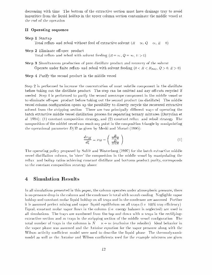
Figure 8: Product sequence in batch extractive distillation of ethanol and water by ethyleneglycol producing: 1. pure ethanol (step 3), 2. an o�-cut, 3. pure water (step 4), and 4. asecond o�-cut to purify the ethylene glycol solvent left in the reboiler for re-use (step 5). E=1.0kmol/hr, R=3, N=30, H(0)=10 kmol, V=5.0 kmol/hr.
Since the relative volatility between ethanol and ethylene glycol is especially large and theseparation in the rectifying section only required few trays and low re ux, pure ethanol was
13

0 hr
Ethylene glycol Water
Ethanol
Az
9.12 hr
Figure 9: Composition trajectory of the reboiler (from 0 to 9.12 hours) in the batch extractivedistillation column separating ethanol and water using ethylene glycol as extractive solvent.E=1.0 kmol/hr, R=3, N=30, H(0)=10 kmol, V=5.0 kmol/hr.
achieved during all the operation. Thus, the speci�c example of separation of ethanol and waterby ethylene glycol is not useful for illustration of the degradation of the column pro�le andthe decreased separation e�ciency. In the second example mixture of acetone and methanol bywater this was more apparent. The spesi�cations and operating parameters for the simulationsshown in �gure 12 to 16 were:
� The initial charge to the reboiler was 5 kmol of 50 mol% acetone and 50 mol% methanol.
� The total number of theoretical trays in the column sections was 40 (20 trays in therectifying section inclusive the solvent feed tray, and 20 trays in the extractive section).
� The extractive solvent feed was introduced on tray number 20 at a constant feed owrate.
� The simulation was terminated when the reboiler was empty on the second methanolproduct (molefraction of methanol < 1 �10�6). The practical extractive distillation processshould not be continued to the �nal times presented in the �gures.
� Note that alle the results presented are open loop simulations (no attemt to control thecomposition of the middel vessel).
14
0 1 2 3 4 5
0
0.1
0.2
0.3
0.4
0.5
0.6
0.7
0.8
0.9
1
Mo
le fra
ctio
n in
dis
tilla
teEthanol Water Ethylene glycol
Step 3
Time [hr]
Step 5Step 4off-cut
Figure 10: Product sequence in batch extractive distillation of ethanol and water by ethyleneglycol producing: 1. pure ethanol (step 3), 2. an o�-cut, 3. pure water (step 4), and 4. asecond o�-cut to purify the ethylene glycol solvent left in the reboiler for re-use (step 5). E=1.0kmol/hr, R=1.5, N=30, H(0)=10 kmol, V=5.0 kmol/hr.
0 hr
Ethylene glycol Water
Ethanol
Az
5.71 hr
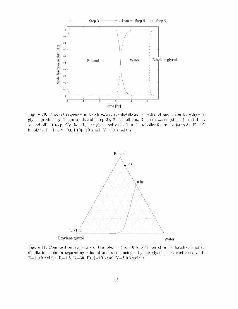
Figure 11: Composition trajectory of the reboiler (from 0 to 5.71 hours) in the batch extractivedistillation column separating ethanol and water using ethylene glycol as extractive solvent.E=1.0 kmol/hr, R=1.5, N=30, H(0)=10 kmol, V=5.0 kmol/hr.
15

0 1 2 3 4 5 6 7
0
0.1
0.2
0.3
0.4
0.5
0.6
0.7
0.8
0.9
1
Time [hr]
WaterM
ole
fra
ctio
n in
dis
tilla
teAcetone Methanol
Step 5Step 4Step 3off-cut
Figure 12: Product sequence in batch extractive distillation of acetone and methanol by waterproducing: 1. pure acetone (step 3), 2. an o�-cut, 3. pure methanol (step 4), and 4. a secondo�-cut to purify the water solvent left in the reboiler for re-use (step 5). E=2.0 kmol/hr untilthe distillate purity of acetone is less than the azeotropic composition (< 0.786) (in this case nosolvent feed after 3.17 hours), R=5, N=40, H(0)=5 kmol, V=5.0 kmol/hr.
Az
MethanolWater
Acetone
0 hr
7.64 hr
Figure 13: Composition trajectory of the reboiler (from 0 to 6.88 hours) in the batch extractivedistillation column separating acetone and methanol using water as extractive solvent. E=2.0kmol/hr until 3.17 hr, R=5, N=40, H(0)=10 kmol, V=5.0 kmol/hr.
16

0 0.5 1 1.5 2 2.5 3 3.5 4 4.5 5
0
0.1
0.2
0.3
0.4
0.5
0.6
0.7
0.8
0.9
1
Time [hr]
Water
Mo
le fra
ctio
n in
dis
tilla
te
Acetone Methanol
Step 5Step 4Step 3off-cut
Figure 14: Product sequence in batch extractive distillation of acetone and methanol by waterproducing: 1. pure acetone (step 3), 2. an o�-cut, 3. pure methanol (step 4), and 4. a secondo�-cut to purify the water solvent left in the reboiler for re-use (step 5). E=2.0 kmol/hr untilmethanol breakthrough in distillate (impurity of methanol is more than the azeotropic compo-sition (< 0.214) (no solvent feed after 2.0 hours), R=3, N=40, H(0)=5 kmol, V=5.0 kmol/hr.
Az
MethanolWater
Acetone
5.0 hr
0 hr
Figure 15: Composition trajectory of the reboiler (from 0 to 5.0 hours) in the batch extractivedistillation column separating acetone and methanol using water as extractive solvent.
17

H 2
H 3
1
H
H
54
H6
H
E
Acetone
Az
MethanolWater
D
Figure 16: Instantaneous composition pro�les in the batch extractive distillation column withsequential removal of products separating acetone (1) and methanol (2) by water (solvent). D -distillate, E - solvent feed tray, H - instantaneous reboiler composition.
In the �rst instance of the process (after initial feed of solvent), the composition of the reboileris marked by H1 in �gure 16. For each time step, the composition of the reboiler gets enriched inthe water solvent, marked by H1, H2, H3, H4, H5, H6, and it becomes more and more di�cultto get pure distillate acetone product. Thus, the separation e�ciency decreases with time inthe extractive section. When the composition of the reboiler reaches the binary edge, all of theacetone product is taken out as distillate and only the separation of methanol (second product)and the water (solvent) remains, i.e. regeneration of the solvent for re-use.
Thus, for the conventinal batch extractive distillation column con�guration, there is a trade-o�between two operating schemes: (1) requiring pure distillate product with decreasing separatione�ciency during the batch distillation run, or (2) removing a binary distillate fraction of the �rstproduct and solvent and purify this fraction in a second column (or in a later batch distillationstep). The choice between these two modes depends on the relative volatility between the solventand the �rst distillate product and has to be considered in each speci�c case. For the examplemixture of ethanol and water, pure ethanol was achieved during the whole distillation run dueto the high relative volatility between ethanol and ethylene glycol and it was su�cient witha few trays in the rectifying column. For the example mixture of acetone and methanol, theseparation of acetone from water is more di�cult due to the formation of an almost tangentazeotrope as previously described.
Summary: The batch extractive distillation column con�guration with sequential removal ofproducts has two main disadvantages due to the gradual accumulation of the high-boiling solventin the reboiler: (1) �lling of the reboiler, and (2) depletion of the azeotrope components in thereboiler which causes a degradation of column pro�le. The �rst may cause operational problemsand the latter decreases the e�ciency of the separation.
18

4.2 Batch Extractive Distillation with a Middle Vessel
In the second con�guration studied, the batch extractive middle vessel column, removal of distil-late products and recovery of the extractive agent was performed simultaneously. As previouslymentioned, the composition of the middle vessel vary depending on the re ux- and reboil ra-tios during operation. The best operating policy is probably to hold the composition of thedistillate and bottoms product constant by 'steering' the composition of the middle vessel bymanipulating the extractive solvent feed owrate and the reboiler- and re ux ratios (Safrit andWesterberg 1997). In this study, only a simple operating policy was implemented with constantreboiler- and re ux ratios. The speci�cations and operating parameters for the examples givenin the �gures were:
� The initial charge to the middle vessel is 5 kmol of 50 mol% acetone and 50 mol% methanol.
� The total number of theoretical trays in the column sections was 60 (20 trays in therectifying section inclusive the solvent feed tray, 20 trays in the extractive section and 20trays in the stripping section).
� A constant vapor ow of 5.0 kmol/h (maximum boilup) was set to minimize the timeconsumption of the batch run as for the previous sequential batch extractive distillationexample.
� The extractive solvent feed was introduced on tray number 20 at a constant feed owrateof 2.0 kmol/h, i.e. E=V = 0:40 (see �gure 22 for the explanation of the symbols).
� The re ux ratio was held at R = 3 constant and the liquid ow out of the middle vesselwas held constant at LM = L1+D+E during the two operating regimes of steps 3 and 4.The molar holdup in the reboiler and condenser was set constant to 0:01 kmol. The valuesgiven above gives a liquid re ux owrate from the condenser of L1 = 3:75 kmol/h and adistillate owrate of D = 1:25 kmol/h. Thus, the liquid owrate out of the middle vesselwas set to L1 = 7:0 kmol/h when extractive solvent was fed, and the bottoms owrate wasB = 2 kmol/h when extractive solvent was fed and B = 0 (total boilup) without extractivesolvent feed. The values are by no means ment to be optimal for operation of the middlevessel column.
� The simulation was terminated when the middle vessel was empty on methanol (molefrac-tion of methanol < 1 � 10�6).
� Note that alle the results presented are open loop simulations. No attemt was made tocontrol the composition of the middel vessel. The operation of the extractive distillation(with solvent feeding) should not continue on to the �nal times presented in the �gures.
19

0 0.5 1 1.5 2 2.5 3 3.5
0
0.1
0.2
0.3
0.4
0.5
0.6
0.7
0.8
0.9
1
Time [hr]
Methanol
Mo
le fra
ctio
n in
dis
tilla
te
Step 3
Acetone
off-cut
Figure 17: Distillate product sequence in batch extractive middle vessel distillation of acetoneand methanol by water producing: 1. pure acetone (step 3) and 2. an o�-cut. E=2.0 kmol/hrand Q=2.5 until 1.89 hours and E=0 kmol/hr and total boilup after that, R=3, N=60,HM (0)=5kmol.
0 0.5 1 1.5 2 2.5 3 3.5
0
0.1
0.2
0.3
0.4
0.5
0.6
0.7
0.8
0.9
1
Time [hr]
Methanol
Mo
le f
ract
ion
in b
ott
om
off-cut
Acetone
Water
pure extractive solvent
Figure 18: Bottoms product sequence in batch extractive middle vessel distillation of acetoneand methanol by water producing: 1. an o�-cut and 2. pure extractive solvent (water). E=2.0kmol/hr and Q=2.5 until 1.89 hours, R=3, N=60, HM(0)=5 kmol.
20

1.89 hr
Az
MethanolWater
3.96 hr
0 hr
Figure 19: Composition trajectory of the middle vessel (from 0 to 3.96 hours) in the batchextractive distillation column separating acetone and methanol using water as extractive solvent.E=2.0 kmol/hr and Q=2.5 until 1.89 hours, R=3, N=50, HM(0)=5 kmol.
Figure 20, 21 and 20 shows instantaneous composition pro�les along the batch extractive middlevessel distillation column separating acetone and methanol using water as extractive solvent.
Summary: The batch extractive middle vessel distillation column con�guration solves thepreviously mentioned problem of solvent accumulation in the reboiler of the conventional batchcolumn con�guration. The volume of the middle vessel can be kept constant or even decreasingwith time due to the depletion of the high-boiling agent to the stripping section of the column.In addition, the batch extractive middle vessel column is potentially more energy e�cient due tothe multi-e�ect nature of combining a rectifying-extraction section and a stripper section in onecolumn (only one condenser and reboiler, and simultaneous removal of products and recoveryof the entrainer, i.e. time savings in operation), even when compared to continuous extractivedistillation columns (comparable to a direct sequence of two columns). The extractive middlevessel column has a more complex design, but is more exible and easier to operate. Severalaspects of extractive distillation in batch columns remains to be answered such as optimal policyfor feed of extractive solvent, required quality (purity, temperature) of the solvent feed, solventfeed tray location, re ux policy and others.
21

Az
MethanolWater
E
DAcetone
1.5 hours
M
B
Figure 20: Instantaneous composition pro�le (snapshot at 1.5 hours) in the batch extractivemiddle vessel distillation column separating acetone and methanol using water as extractivesolvent. D - distillate, B - bottoms product, M - middle vessel composition, E - solvent feedtray.
55 60 65 70 75 80 85 90 950
10
20
30
40
50
60
70
Tra
y nu
mbe
r (f
rom
bot
tom
and
up)
Temperature ( C)o
1.5 hours
E
C
M
B
Figure 21: Instantaneous temperature pro�le (snapshot at at 1.5 hours) in the batch extractivemiddle vessel distillation column separating acetone and methanol using water as extractivesolvent. C - condenser (distillate), B - bottoms product, M - middle vessel composition, E -solvent feed tray.
22

4.3 Comment on Control
According to Doherty and Knapp (1993), it is widely recognized that azeotropic distillationcolumns are di�cult to operate and control because these columns may exhibit complex dynamicbehavior and parametric sensitivity. However, using the proper control con�guration, extractivedistillations are no more di�cult to control than ordinary distillation columns producing highpurity products (Jacobsen and Skogestad (1991)).
Farschman and Diwekar (1996) evaluate various control con�gurations (dual composition con-trol) for the batch distillation middle vessel column con�guration for separation of ideal ternarymixtures. They use the ratio of the vapor ow in the rectifying section to the vapor ow in thestripping section as a control parameter (this ratio q was discussed in the paper by Davydianet al. (1994)). In this study, the vapor ow is held constant in both column sections equal tothe maximum boilup (q = 1). Andersen et al. (1995) studied the e�ect of design on operationof continuous extractive distillation. The second feed of extractive solvent (called entrainer) tothe distillation column introduces an additional design variable which does not exist in con-ventional distillation. They showed that for continuous systems, this degree of freedom can beconveniently expressed as a relation between the extractive solvent feed owrate and the inter-nal ows for �xed product speci�cations, E=V . The e�ects which govern the trade-o� curve aresummarized as follows (Andersen et al. 1995):
Entrainer feed owrate
� (Ea) Increasing the entrainer feed ow increases the relative amount of en-
trainer in the extractive section and thus improves the relative volatility betweenthe light and the intermediate components.
� (Eb) Increasing the entrainer feed ow increases the load on the rectifying andstripping sections.
Internal ows
� (Ia) Increasing the internal ows improves the operating lines in the strippingand rectifying sections.
� (Ib) Increasing the internal ows reduces the relative amount of entrainer in
the extractive section and thus reduces the relative volatility between the lightand intermediate components.
Control structure for the batch extractive middle vessel distillation column
In nonideal systems, the notation light, intermediate and heavy component may be misleading.The relative volatility order between the components may vary in the composition space andis not determined simply from the pure components boiling-points. For continuous extractivedistillation of an azeotropic system as given in �gure 1, component 1 is more volatile thancomponent 2 in the rectifying section, but opposite in the extractive and stripping sections. Theextractive solvent is least volatile component in the whole composition space thus the notionheavy component may be used.
Step 3 (production of acetone): In the rectifying section, separation of the extractivesolvent form component 1 (light component) dominates and we propose to control the amountof solvent in the distillate by adjusting the liquid ow from the condenser L1 as for conventional
23

distillation columns. In the extractive section, the azeotrope components are separated in thedilution of the extractive solvent. The separation e�ciency improves with increased load ofthe extractive solvent and the solvent feed amount is determinant for the separation. Thus,we propose to control the purity of the light component (component 1) from this section byadjusting the extractive solvent feed owrate (keeping the fromt of the intermediate componentin the extractive section at a certain level).
In the stripping section (during step 3), separation of component 2 (intermediate component)from the solvent dominates and we propose to control the impurity of intermediate componentin the bottoms product, or, alternatively the impurity (amount) of solvent in the middle vessel,by adjusting the liquid ow form the middle vessel LM ('second re ux ratio').
H , xB B
H , xD D
x 2
TC
CC
Middle Vessel
Condenser
E
Reboiler
VMaximum Heat
D
Solvent
Solvent Feed
B
MH , x M
L
L1
ML
N
"Pure" 1
Figure 22: Control con�guration of the batch extractive distillation column with a middle vessel
Maximum boilup set to 5.0 kmol/hr was used in all simulations without bottoms product removal(total reboil) in order to minimize the time consumption of the batch run. In the cases withbottoms product removal, the reboil ratio is held constant. The liquid ow out of the middlevessel LM , was held constant equal 5.0 kmol/hr in simulations without control.
Feedback control on the product compositions
For the separation of ethanol and water using ethylene glycol as extractive solvent, the temper-ature is (relatively) insensitive to composition changes in the extractive section due to the largeamount (dilution) of the solvent on the trays. Since the composition of ethanol and water is nota strong function of temperature in the extractive section we propose to use a measurement or
24
estimate of the composition of component 2 as input for the control of the extractive solventfeed owrate (controls the separation of the azeotrope components, which again obviously a�ectsthe purity of distillate composition). Speci�c gravity (density) measurements of the condenseddistillate ow may be used, but there will be a time delay between a change in composition inthe vapor ow out of the rectifying section is registered in the distillate ow out of the condenserdrum. Alternatively, the composition of component 2 in the vapor leaving the rectifying section,or composition of component 2 in the extractive section, can be measure directly by IR or GCanalysis (time delay in measurements).
In the stripping section (during step 3), the temperature is more sensitive to composition changesand we propose to adjust the middle vessel holdup indirectly by manipulating the re ux ow outof the vessel to control the temperature at some location in the column section below (schemeof Skogestad et al. (1995)).
5 Conclusion
This paper focuses on the use of batch extractive distillation for separating homogeneous minimum-boiling azeotropic mixtures, where the extractive agent is a high-boiling, miscible zeotropic com-ponent. In conventional batch column con�guration, the extractive scheme breaks the azeotropeand the components can be recovered as pure products (sequential removal of the products).However, this semi-continuous operation has two main disadvantages due to accumulation ofthe extractive agent: (1) �lling of the reboiler, and (2) degradation of the composition pro�le inthe column. The �rst may cause operational problems and the latter decreases the e�ciency ofthe separation. The middle vessel column arrangement overcome these problems since it allowsfor simultaneous removal of pure products and recovery of the extractive agent. The volumeof the middle vessel can be kept constant or even decreasing with time. Thus, high separatione�ciency can be achieved since the sharpness of the column pro�le is maintained.
Batch extractive distillation with a middle vessel is closely related to the well-known continuousextractive distillation except that the separation is performed in one rather than in two columns,which may imply capital savings for the batch implementation. Furthermore, the batch imple-mentation is potentially more energy e�cient due to the combination of a rectifying-extractionsection and a stripper section in one column.
We propose a novel control con�guration for the batch extractive middle vessel distillation wherethe liquid ow from the middle vessel is manipulated to control the temperature in the strippingsection, achieving a desired purity of the extractive agent. This indirectly adjusts the vesselholdup so there is no need for level control. The extractive agent feed is used to control thepurity of the distillate and the re ux is held constant below its maximum value.
Acknowledgment
We thank Dr. V. N. Kiva for providing valuable insight to the batch extractive distillationprocess and operation of the middle vessel column con�guration, as well as giving references torelevant publications in the Russian literature.
25

Terms and Concepts
Azeotrope - mixture whose composition corresponds to an extremal point (minimum, maximum orsaddle point) on the boiling temperature isobar. In the azeotropic point the vapor and liquidcompositions are equal.
Azeotropic - mixtures that form one or several extremal points (minimum,maximum or saddle points)on the boiling temperature isobar at atmospheric or any other pressure, or, equivalently, that formone or several points on the vapor pressure isotherm.
Azeotropic distillation - distillation of an azeotropic mixture and/or distillation with addition of aseparating agent forming new azeotropes in the system. Includes single and multiple feed columns.
Distillation (fractional distillation) - sequence of partial vaporization steps where the vapor phasebecomes gradually enriched in the most volatile component(s), i.e. a cascade of equilibrium trays.
Extractive distillation - distillation of zeotropic and/or azeotropic mixtures with addition of a rel-atively non-volatile component (usually called solvent) selective to one of the components in thefeed mixture taken out as bottoms product. The solvent is introduced above the mixture feed in asecond feed point to the distillation column.
Homoazeotrope - azeotrope where the vapor phase coexists with one liquid phase.
Homoazeotropic distillation - distillation of homoazeotropic mixtures and/or with the addition of aliquid separating agent that is completely miscible.
RCM - (simple distillation) residue curve map. Diagram which shows the locus of the composition ofthe residue liquid in the still during simple distillation for di�erent initial conditions.
Simple distillation (or open evaporation) - evaporation of a liquid phase where the vapor formedis removed continuously (Rayleigh distillation).
Simple distillation residue curve - the locus of the composition of the residue liquid in the stillduring simple distillation (open evaporation). Introduced by Schreinemakers in 1901 and termedthe distillation line of the liquid in the Russian literature.
Zeotropic - (ideal or nonideal) mixtures that do not form azeotropes.
26

Notation
Aij binary interaction parameter in the Wilson equation [cal=mol]B bottom ow for stripping (inverted) column [kmol=hr]D distillate ow for rectifying (regular) column [kmol=hr]E extractive agent feed [kmol=hr]F feed amount [kmol]F0 basic feed amount (before adding separating agent) [kmol]FT total feed amount to column (basic feed + added separating agent) [kmol]H(0) initial liquid molar holdup in reboiler (or still) [kmol]H(t) liquid molar holdup in reboiler (or still) at time t [kmol]Hj liquid molar holdup on tray j [kmol]L molar liquid ow rate [kmol=hr]N total number of trays in the column (excl. reboiler)n number of trays in rectifying sectionm number of trays in stripping sectionnc number of components (in a multicomponent mixture)P total pressure [Pa]P sati saturated vapor pressure of pure component i [Pa = N=m2]
Q boilup ratio, V=BR (1) re ux ratio, L=D; (2) universal gas constant, R = 1:98721 [cal=molK]T temperature [K]t time [hr]Vi molar volume of component i [cm3=mol]V molar vapor ow rate [kmol=hr]x vector of mole fractions in the liquid phase (nc elements)y vector of mole fractions in the vapor phase (nc elements)xi mole fraction of component i in the liquid phaseyi mole fraction of component i in the vapor phase
Greek letters
� relative volatility liquid activity coe�cient
� dimensionless warped time variable; � = �ln H(t)H(0)
Subscripts
B bottom, reboiler (or still)D distillate, condenserM middle vesselS solvent, separating agent, entrainer0 initial value (at t = 0)1; 2; 3 components number
27

References
Andersen, H. W., Laroche, L. and Morari, M. (1995). E�ect of design on the operation ofhomogeneous azeotropic distillation., Comp. Chem. Eng. 19(1): 105{122.
Barolo, M., Guarise, G. B., Ribon, N., Rienzi, S. A., Trotta, A. and Macchietto, S. (1996a).Some issues in the design and operation of a batch distillation column with a middle vessel,Comp. Chem. Engng. 20(Suppl.): S37{S42.
Barolo, M., Guarise, G. B., Rienzi, S. A., Trotta, A. and Macchietto, S. (1996b). Running batchdistillation in a column with a middle vessel, Ind. Eng. Chem. Res. 35: 4612{4618.
Bauer, M. H. and Stichlmair, J. (1995). Synthesis and optimization of distillation sequences forthe separation of azeotropic mixtures, Comp. Chem. Engng. 19: S15{S20.
Benedict, M. and Rubin, D. R. (1945). Extractive and azeotropic distillation,Trans. Am. Inst. Chem. Eng. 41: 353{370.
Berg, L. (1969). Azeotropic and extractive distillation: Selecting the agent for distillation,Chem. Eng. Prog. 65(9): 52{57.
Bortolini, P. and Guarise, G. B. (1970). A new method of batch distillation (In Italian),Quad. Ing. Chim. Ital. 6: 1{9.
Davydian, A. G., Kiva, V. N. and Platonov, V. M. (1991a). Batch distillaiton in atwo-section column with a middle reservoir under equal vapour ows in the sections,Theor. Found. Chem. Eng., Russian 25(6): 771{782.
Davydian, A. G., Kiva, V. N. and Platonov, V. M. (1991b). Investigation of binary mixturesseparation in two-section batch column with a middle reservoir, Theor. Found. Chem. Eng.,
Russian 25(4): 467{475.
Davydian, A. G., Kiva, V. N. and Platonov, V. M. (1992a). Batch distillaiton in two-section column with a middle reservoir under di�erent vapour ows in the sections,Theor. Found. Chem. Eng., Russian 26(2): 163{172.
Davydian, A. G., Kiva, V. N. and Platonov, V. M. (1992b). Batch distillaiton of multicomponentmixtures in two-section column with a middle reservoir, Theor. Found. Chem. Eng., Russian26(4): 467{477.
Davydian, A. G., Kiva, V. N. and Platonov, V. M. (1993). Minimum re ux ratio regime for batchdistillaiton with a middle reservoir, Theor. Found. Chem. Eng., Russian 27(4): 373{380.
Davydian, A. G., Kiva, V. N., Meski, G. A. and Morari, M. (1994). Batch distillation with amiddle vessel, Chem. Eng. Sci. 49(18): 3033{3051.
D�ussel, R. and Stichlmair, J. (1995). Separation of azeotropic mixtures by batch distillationusing an entrainer, Comp. Chem. Eng. 19(Suppl.): S113{S118.
Doherty, M. F. and Knapp, J. F. (1993). Distillation, Azeotropic and Extractive, Vol. 8, fourthedn, Kirk-Othmer Enc. Chem. Tech.
Farschman, C. and Diwekar, U. (1996). Dual composition in a novel batch distillation column,1996 AIChE Annual Meeting,Chicago, November.
28

Hasebe, S., Abdul Aziz, B., Hashimoto, I. and Watanabe, T. (1992). Optimal design and oper-ation of complex batch distillation column, Proc. IFAC Workshop on Interactions BetweenProcess Design and Process Control, London (UK).
Hasebe, S., Kurooka, T. and Hashimoto, I. (1995). Comparison of the separation performancesof a multi-e�ect batch distillation system and a continuous distillation system, PreprintsIFAC Symposium DYCORD+'95, Elsinore (Denmark), June. Danish Automation Society:Copenhagen.
Jacobsen, E. W. and Skogestad, S. (1991). Multiple steady{states in ideal two{product distilla-tion, AIChE J. 37(4): 499.
Kiva, V. N. (1997). Private communication, Karpov Institute of Physical Chemistry, Laboratoryof Mixtures Separation, Moscow.
Knapp, J. P. and Doherty, M. F. (1990). Thermal integration of homogeneous azeotropic distil-lation sequences, AIChE J. 36(7): 969{984.
Knapp, J. P. and Doherty, M. F. (1994). Minimum entrainer ow for extractive distillation: abifurcation theoretic approach, AIChE J. 40(2): 243{268.
Kogan, V. B. (1971). Azeotropic and Extractive Distillation, Vol. 2d edition, Chemistry Pub-lishing Co. Leningrad.
Lang, P., Lelkes, Z., Moszkowicz, P., Otterbein, M. and Yatim, H. (1995). Di�erent operationalpolicies for the batch extractive distillation, Comp. Chem. Engng. 19(Suppl.): S645{S650.
Lang, P., Yatim, H., Moszkowicz, P. and Otterbein, M. (1994). Batch extractive distillationunder constant re ux ratio, Comp. Chem. Engng. 18(11/12): 1057{1069.
Laroche, L., Bekiaris, N., Andersen, H. W. and Morari, M. (1993). Homogeneous azeotropicdistillation: Comparing entrainers, Can. J. Chem. Eng. 69(Dec.): 1302{1319.
Levy, S. G. and Doherty, M. F. (1986). Design and synthesis of homogeneous azeotropic distilla-tions. 4. minimum re ux calculations for multiple-feed columns, I&EC Fund. 25: 269{279.
Meski, G. A. and Morari, M. (1995). Design and operation of a batch distillation with a middlevessel, Comp. Chem. Eng. 19(Suppl.): S597{S602.
Perry, R. H. and Chilton, C. H. (1973). Chemical Engineers' Handbook, Chem. Engng. Series,�fth edn, McGraw Hill, Inc. Chapter 13.
Robinson, C. S. and Gilliland, E. R. (1950). Elements of Fractional Distillation, Vol. 4, McGrawHill, Inc., New York.
Safrit, B. T. and Westerberg, A. W. (1997). Improved operational policies for batch extractivedistillation columns, Ind. Eng. Chem. Res. 36: 436{443.
Safrit, B. T., Westerberg, A. W., Diwekar, U. and Wahnscha�t, O. M. (1995). Extendingcontinuous conventional and extractive distillation feasibility insights to batch distillation,Ind. Eng. Chem. Res. 34: 3257{3264.
Skogestad, S., Wittgens, B., S�rensen, E. and Litto, R. (1995). Multivessel batch distillation,Presented at the AIChE Annual Meeting, Miami Beach, November. Paper 184i.
29

SpeedUp (1993). Release 5.4 user manual, Prosys Technology Ltd. SpeedUp version 5.5-5 usedin the simulations.
Van Winkle, M. (1967). Distillation, Chem. Engng. Series, McGraw Hill, Inc. Part 3: Chapters9-11.
Yatim, H., Moszkowicz, P. and Otterbein, M.and Lang, P. (1993). Dynamic simulation of abatch extractive distillation process, Comp. Chem. Eng. 17(Suppl.): S57{62.
30
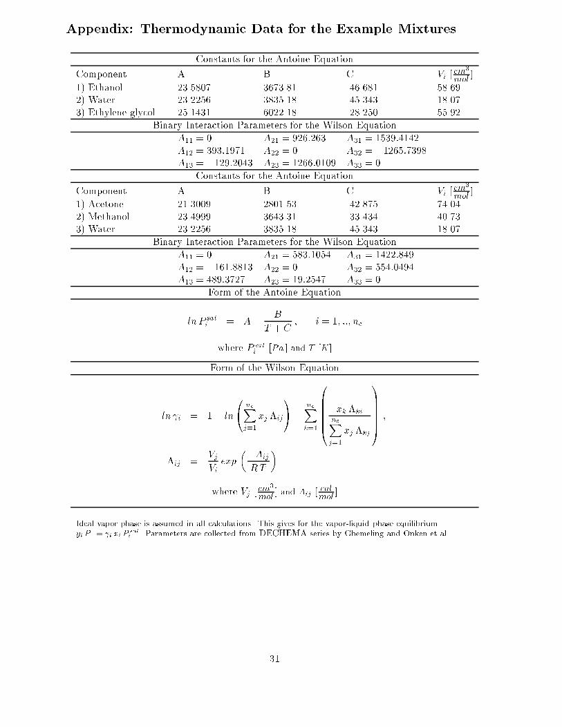
Appendix: Thermodynamic Data for the Example Mixtures
Constants for the Antoine Equation
Component A B C Vi [cm3
mol]
1) Ethanol 23.5807 3673.81 -46.681 58.692) Water 23.2256 3835.18 -45.343 18.073) Ethylene glycol 25.1431 6022.18 -28.250 55.92
Binary Interaction Parameters for the Wilson Equation
A11 = 0 A21 = 926:263 A31 = 1539:4142A12 = 393:1971 A22 = 0 A32 = �1265:7398A13 = �129:2043 A23 = 1266:0109 A33 = 0
Constants for the Antoine Equation
Component A B C Vi [cm3
mol]
1) Acetone 21.3009 2801.53 -42.875 74.042) Methanol 23.4999 3643.31 -33.434 40.733) Water 23.2256 3835.18 -45.343 18.07
Binary Interaction Parameters for the Wilson Equation
A11 = 0 A21 = 583:1054 A31 = 1422:849A12 = �161:8813 A22 = 0 A32 = 554:0494A13 = 489:3727 A23 = 19:2547 A33 = 0
Form of the Antoine Equation
ln P sati = A�
B
T + C; i = 1; ::; nc
where P sati [Pa ] and T [K]
Form of the Wilson Equation
ln i = 1� ln
0@ ncXj=1
xj �ij
1A�
ncXk=1
0BBBBB@
xk �ki
ncXj=1
xj �kj
1CCCCCA ;
�ij =VjVi
exp
��Aij
RT
�
where Vj [cm3
mol] and Aij [
calmol
]
Ideal vapor phase is assumed in all calculations. This gives for the vapor-liquid phase equilibriumyi P = i xi P
sat
i . Parameters are collected from DECHEMA series by Ghemeling and Onken et al.
31