|in| gate-2017-paper instrumentation engineeringgfweb.s3.amazonaws.com/gatepapers/gate2017/in-gate...
TRANSCRIPT

|IN| GATE-2017-PAPER www.gateforum.com
ICP–Intensive Classroom Program eGATE-Live Internet Based Classes DLP TarGATE-All India Test Series Leaders in GATE Preparations 65+ Centers across India
© All rights reserved by Gateforum Educational Services Pvt. Ltd. No part of this booklet may be reproduced or utilized in any form without the written permission.
1
Instrumentation Engineering
Q. No. 1 to 25 Carry One Mark Each
1. A system is described by the following differential equation:
dy t dx t
2y t x t ,x 0 y 0 0dt dt
Where x(t) and y(t) are the input and output variables respectively. The transfer function of the
inverse system is
(A) s 1
s 2
(B)
s 2
s 1
(C)
s 1
s 2
(D)
s 1
s 2
Key: (B)
Exp: We know for inverse system
I
I I
h t *h t t
X S1 1H S H t H S
Y SH S Y SX S
So the transfer function of inverse system is
I
X SH S
Y S
It is given that
dy t dx tzy t x t
dt dt
SY S 2Y S SX S X S
Y S 2 X S S 1
X S S 2
Y S S 1
2. If v is a non-zero vector of dimension 3 1, then the matrix A=vvT
has a rank = _______
Key: 1 to 1
Exp: T T
V is non zero
V.V 1 and V.V V 1
Rank of the matrix
TA V.V is 1
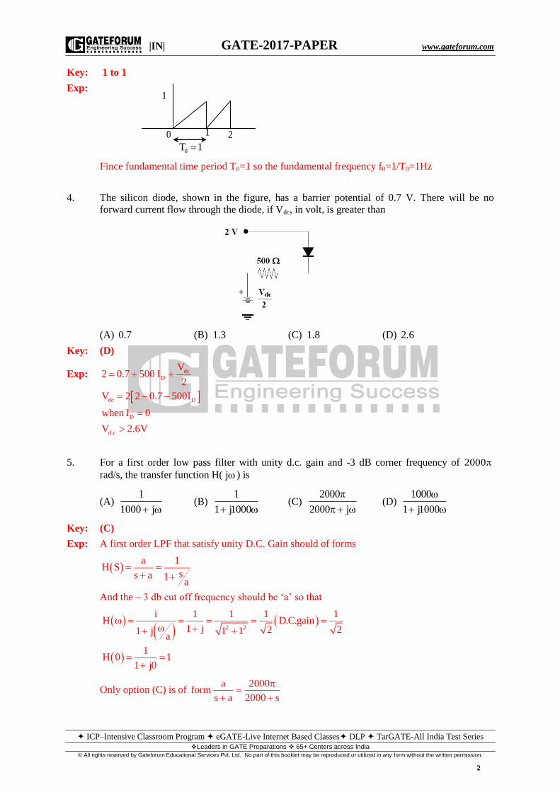
3. A periodic signal x(t) is shown in the figure. The fundamental frequency of the signal x (t) in
Hz is________
|IN| GATE-2017-PAPER www.gateforum.com
ICP–Intensive Classroom Program eGATE-Live Internet Based Classes DLP TarGATE-All India Test Series Leaders in GATE Preparations 65+ Centers across India
© All rights reserved by Gateforum Educational Services Pvt. Ltd. No part of this booklet may be reproduced or utilized in any form without the written permission.
2
Key: 1 to 1
Exp:
Fince fundamental time period T0=1 so the fundamental frequency f0=1/T0=1Hz
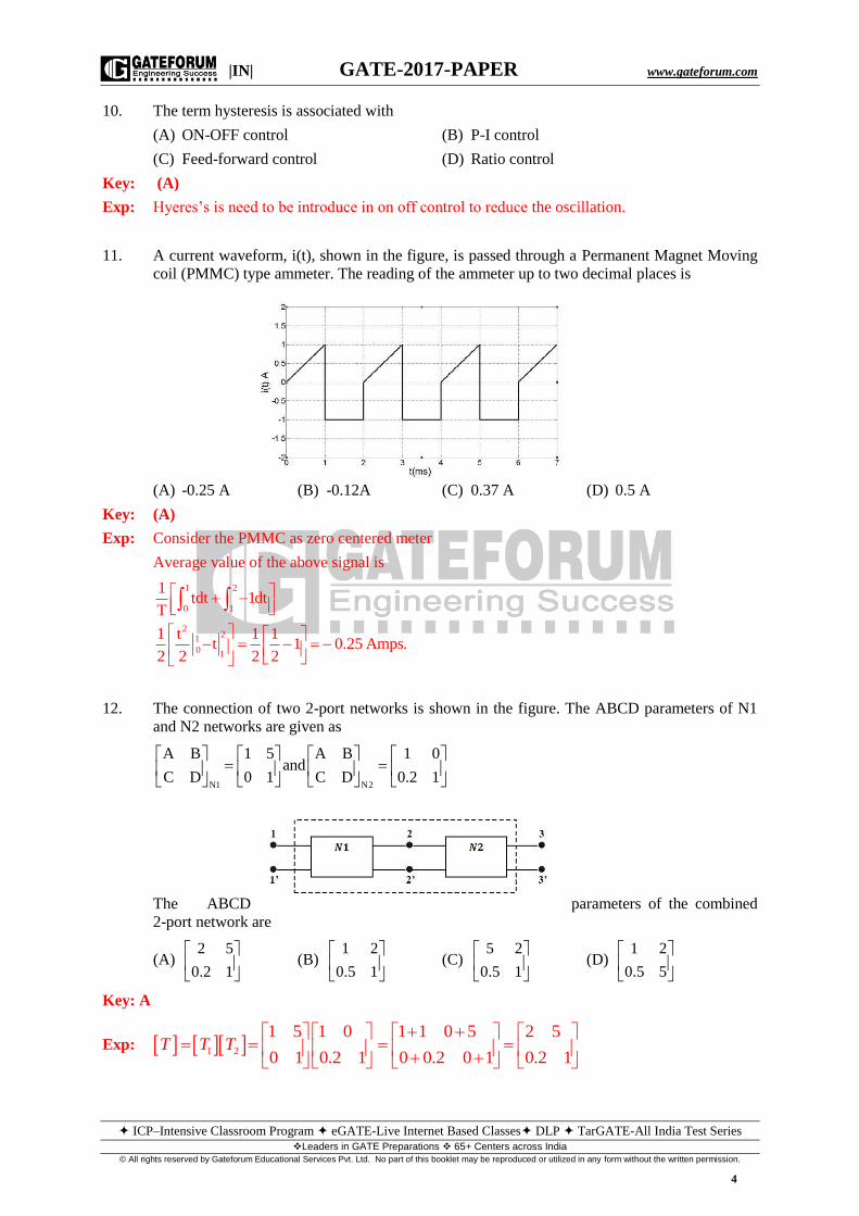
4. The silicon diode, shown in the figure, has a barrier potential of 0.7 V. There will be no
forward current flow through the diode, if Vdc, in volt, is greater than
(A) 0.7 (B) 1.3 (C) 1.8 (D) 2.6
Key: (D)
Exp:
dcD
dc D
D
d.c
V2 0.7 500 I
2
V 2 2 0.7 500I
when I 0
V 2.6V
5. For a first order low pass filter with unity d.c. gain and -3 dB corner frequency of 2000
rad/s, the transfer function H( j ) is
(A) 1
1000 j (B)
1
1 j1000 (C)
2000
2000 j
(D)
1000
1 j1000
Key: (C)
Exp: A first order LPF that satisfy unity D.C. Gain should of forms
a 1
H Sss a 1a
And the – 3 db cut off frequency should be ‘a’ so that
2 2
i 1 1 1 1H D.C.gain
1 j 2 21 11 ja
1H 0 1
1 j0
Only option (C) is of a 2000
forms a 2000 s
0
0T 1
1 2
1

|IN| GATE-2017-PAPER www.gateforum.com
ICP–Intensive Classroom Program eGATE-Live Internet Based Classes DLP TarGATE-All India Test Series Leaders in GATE Preparations 65+ Centers across India
© All rights reserved by Gateforum Educational Services Pvt. Ltd. No part of this booklet may be reproduced or utilized in any form without the written permission.
3
6. A and B are the logical inputs and X is the logical output shown in the figure. The output X is
related to A and B by
(A) X AB BA (B) X AB BA (C) X AB AB (D) X AB BA
Key: (C)
Exp:
7. The most suitable pressure gauge to measure pressure in the range of 4 310 to10 torr is
(A) Bellows (B) Barometer (C) Strain gauge (D) Pirani gauge
Key: (D)
Exp: Pirani Gauge is best suitable for the above range 4 310 to10
torr Application is to measure
“Vacuum Pressure
8. The standard for long distance analog signal transmission in process control industry is
(A) 4-20 mV (B) 0-20mA (C) 4-20mA (D) 0-5V
Key: (C)
Exp: In process industries, the control signal used is
Current → 4-20 mA
Pressure→ 3-15 psi
9. If a continuous-time signal x t cos 2 t is sampled at 4 Hz, the value of the discrete-time
sequence x(n) at n = 5 is
(A) -0.707 (B) -1 (C) 0 (D) 1
Key: (C)
Exp: x t cos 2 t
If the sampling interval is Ts then the sampled signal
s s s
s
2x nT cos 2 nT cos n ; since f 4Hz
f
s
2 n 5x nT x n cos n cos x 5 cos 0
4 2 2
A
B
AB
A B AB
A.B
A
B
|IN| GATE-2017-PAPER www.gateforum.com
ICP–Intensive Classroom Program eGATE-Live Internet Based Classes DLP TarGATE-All India Test Series Leaders in GATE Preparations 65+ Centers across India
© All rights reserved by Gateforum Educational Services Pvt. Ltd. No part of this booklet may be reproduced or utilized in any form without the written permission.
4
10. The term hysteresis is associated with
(A) ON-OFF control (B) P-I control
(C) Feed-forward control (D) Ratio control
Key: (A)
Exp: Hyeres’s is need to be introduce in on off control to reduce the oscillation.
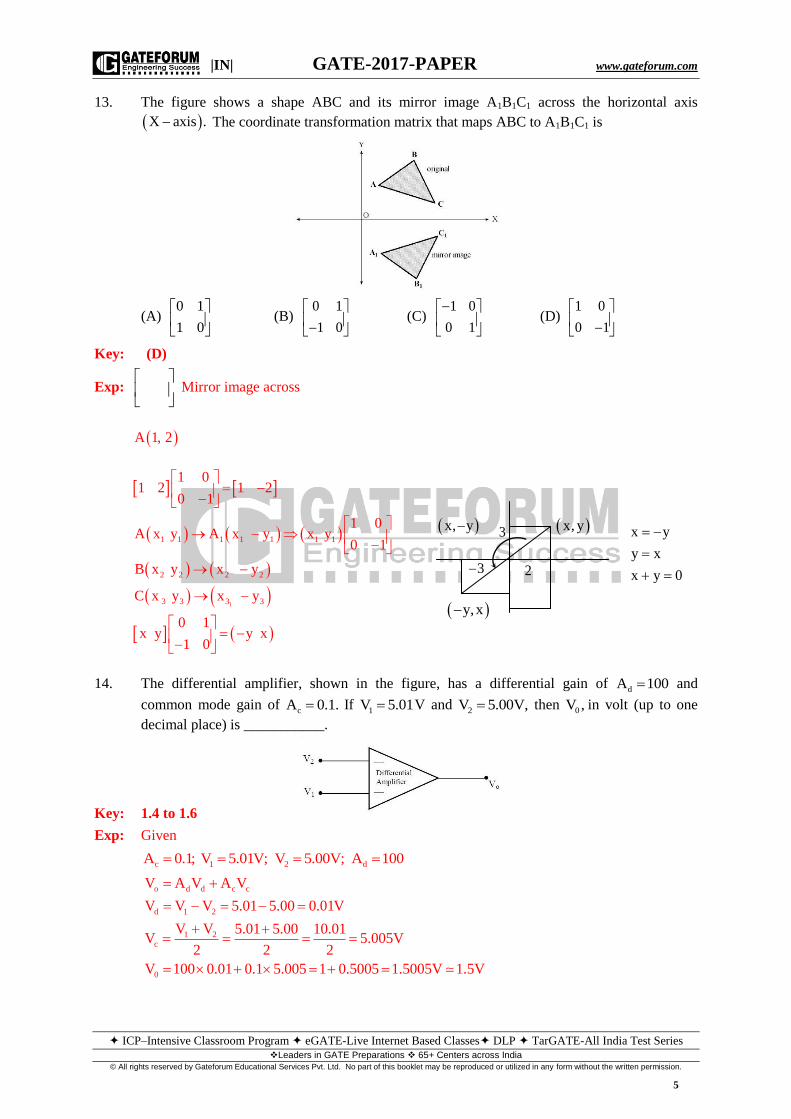
11. A current waveform, i(t), shown in the figure, is passed through a Permanent Magnet Moving
coil (PMMC) type ammeter. The reading of the ammeter up to two decimal places is
(A) -0.25 A (B) -0.12A (C) 0.37 A (D) 0.5 A
Key: (A)
Exp: Consider the PMMC as zero centered meter
Average value of the above signal is
1 2
0 1
22
1
0 1
1tdt 1dt
T
1 t 1 1t 1 0.25 Amps.
2 2 2 2
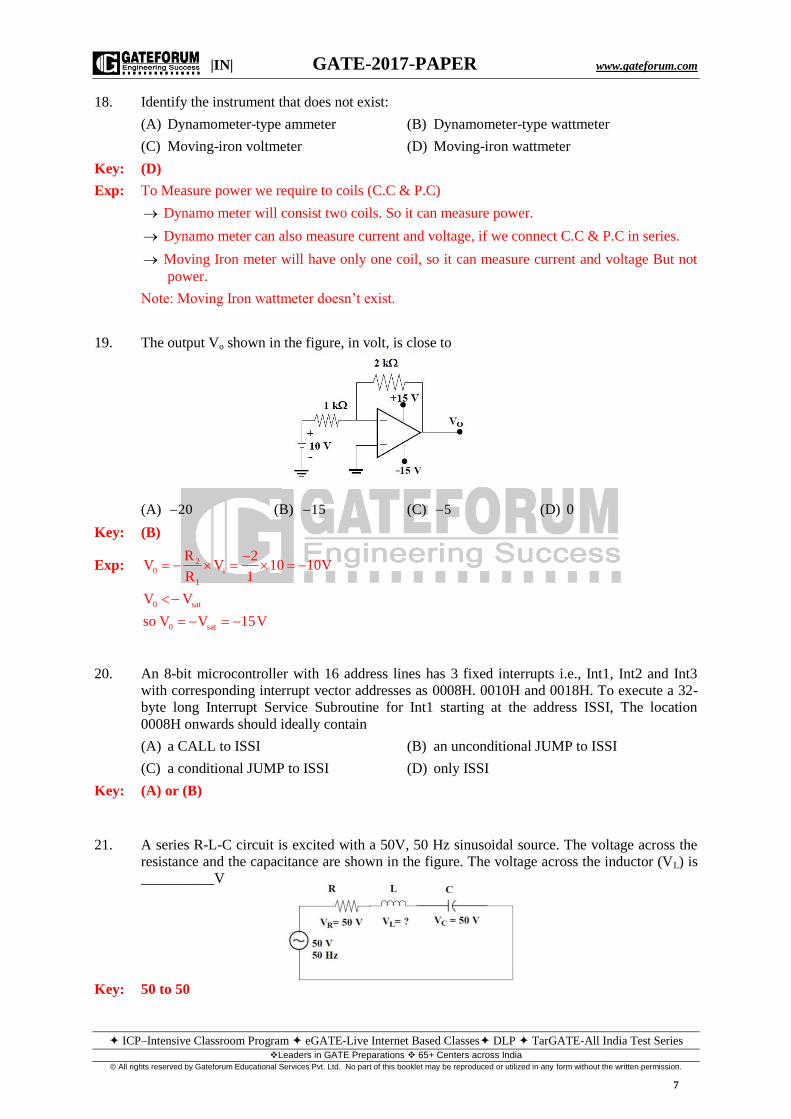
12. The connection of two 2-port networks is shown in the figure. The ABCD parameters of N1
and N2 networks are given as
N1 N2
A B 1 5 A B 1 0and
C D 0 1 C D 0.2 1
The ABCD parameters of the combined
2-port network are
(A) 2 5
0.2 1
(B) 1 2
0.5 1
(C) 5 2
0.5 1
(D) 1 2
0.5 5
Key: A
Exp: 1 2
1 5 1 0 1 1 0 5 2 5
0 1 0.2 1 0 0.2 0 1 0.2 1
T T T
|IN| GATE-2017-PAPER www.gateforum.com
ICP–Intensive Classroom Program eGATE-Live Internet Based Classes DLP TarGATE-All India Test Series Leaders in GATE Preparations 65+ Centers across India
© All rights reserved by Gateforum Educational Services Pvt. Ltd. No part of this booklet may be reproduced or utilized in any form without the written permission.
5
13. The figure shows a shape ABC and its mirror image A1B1C1 across the horizontal axis
X axis . The coordinate transformation matrix that maps ABC to A1B1C1 is
(A) 0 1
1 0
(B) 0 1
1 0
(C) 1 0
0 1
(D) 1 0
0 1
Key: (D)
Exp:
Mirror image across
A 1, 2
1
1 1 1 1 1 1 1
2 2 2 2
3 3 3 3
1 01 2 1 2
0 1
1 0A x y A x y x y
0 1
B x y x y
C x y x y
0 1x y y x
1 0
14. The differential amplifier, shown in the figure, has a differential gain of dA 100 and
common mode gain of cA 0.1. If
1V 5.01 V and 2V 5.00V, then 0V , in volt (up to one
decimal place) is ___________.
Key: 1.4 to 1.6
Exp: Given
c 1 2 dA 0.1; V 5.01V; V 5.00V; A 100
o d d c c
d 1 2
1 2c
0
V A V A V
V V V 5.01 5.00 0.01V
V V 5.01 5.00 10.01V 5.005V
2 2 2
V 100 0.01 0.1 5.005 1 0.5005 1.5005V 1.5V
3
3
2
x, y x, y
y,x
x y
y x
x y 0

|IN| GATE-2017-PAPER www.gateforum.com
ICP–Intensive Classroom Program eGATE-Live Internet Based Classes DLP TarGATE-All India Test Series Leaders in GATE Preparations 65+ Centers across India
© All rights reserved by Gateforum Educational Services Pvt. Ltd. No part of this booklet may be reproduced or utilized in any form without the written permission.
6
15. A circuit consisting of dependent and independent sources is shown in the figure. If the
voltage at Node-1 is – 1 V, then the voltage at Node-2 is _________V.
Key: 2 to 2
Exp: 2
0.5
R1
2 R1 0.5
I 1 1 2A
V 2 0.5 1V
V 1 1 V
V 4V V 1 4 1 1 2V
16. The eigen values of the matrix
1 1 5
A 0 5 6 are
0 6 5
(A) , 6, 51 (B) 1, 5 j6 (C) 1, 5 j6 (D) 1, 5, 5
Key: (C)
Exp: Characteristic equation is
1 1 5
0 5 6 0
0 6 5
2
2
1 5 36 0
1; 10 61 0
10 100 224 10 12j5 j6
2 2
17. The figure shows a phase locked loop. The output frequency is locked at 0f 5kHz. The value
of fi in kHz is __________.
Key: 1 to 1
Exp: 0 i
i
f nf
5f 1kHz
5
2V
1
3
2I
R1V1A
0.5V
1
1A
1
0.5RI4V
22I
|IN| GATE-2017-PAPER www.gateforum.com
ICP–Intensive Classroom Program eGATE-Live Internet Based Classes DLP TarGATE-All India Test Series Leaders in GATE Preparations 65+ Centers across India
© All rights reserved by Gateforum Educational Services Pvt. Ltd. No part of this booklet may be reproduced or utilized in any form without the written permission.
7
18. Identify the instrument that does not exist:
(A) Dynamometer-type ammeter (B) Dynamometer-type wattmeter
(C) Moving-iron voltmeter (D) Moving-iron wattmeter
Key: (D)
Exp: To Measure power we require to coils (C.C & P.C)
Dynamo meter will consist two coils. So it can measure power.
Dynamo meter can also measure current and voltage, if we connect C.C & P.C in series.
Moving Iron meter will have only one coil, so it can measure current and voltage But not
power.
Note: Moving Iron wattmeter doesn’t exist.
19. The output Vo shown in the figure, in volt, is close to
(A) 20 (B) 15 (C) 5 (D) 0
Key: (B)
Exp: 20 i
1
0 sat
0 sat
R 2V V 10 10V
R 1
V V
so V V 15V
20. An 8-bit microcontroller with 16 address lines has 3 fixed interrupts i.e., Int1, Int2 and Int3
with corresponding interrupt vector addresses as 0008H. 0010H and 0018H. To execute a 32-
byte long Interrupt Service Subroutine for Int1 starting at the address ISSI, The location
0008H onwards should ideally contain
(A) a CALL to ISSI (B) an unconditional JUMP to ISSI
(C) a conditional JUMP to ISSI (D) only ISSI
Key: (A) or (B)
21. A series R-L-C circuit is excited with a 50V, 50 Hz sinusoidal source. The voltage across the
resistance and the capacitance are shown in the figure. The voltage across the inductor (VL) is
__________V
Key: 50 to 50

|IN| GATE-2017-PAPER www.gateforum.com
ICP–Intensive Classroom Program eGATE-Live Internet Based Classes DLP TarGATE-All India Test Series Leaders in GATE Preparations 65+ Centers across India
© All rights reserved by Gateforum Educational Services Pvt. Ltd. No part of this booklet may be reproduced or utilized in any form without the written permission.
8
Exp: R
L C L:
bc3 V V 50V The circuit is at resonance
at resonanceV V V 50V
22. The condition for oscillation in a feedback oscillator circuit is that at the frequency of
oscillation, initially the loop gain is greater than unity while the total phase shift around the
loop in degree is
(A) 0 (B) 90 (C) 180 (D) 270
Key: A
23. Let z x jy where j 1. Then cosz
(A) cos z (B) cos z (C) sin z (D) sin z
Key: (B)
Exp: cosz cosz
24. The region of Convergence (ROC) of the Z-transform of a causal unit step discrete-time
sequence is
(A) z 1 (B) z 1 (C) z 1 (D) z 1
Key: (C)
Exp: The Z-transform of unit step sequence is
1 1 1 1
1n 0
1 n
0
1x z u n z z ;| z | 1 | z | 1
1 z
1| z | 1 a only when | a | 1
1 a
11 | z | 1
z
25. The pressure drop across an orifice plate for a particular flow rate is 5 kg/m2. If the flow rate is
doubled (within the operating range of the orifice), the corresponding pressure drop in kg/m3 is
(A) 2.5 (B) 5.0 (C) 20.0 (D) 25.0
Key: (C)
Exp: In case of an orifice plate
2
Q P
Q 5
2Q P
1 5or
2 P
P 5 4 20kg / m
Q. No. 26 to 55 Carry Two Marks Each
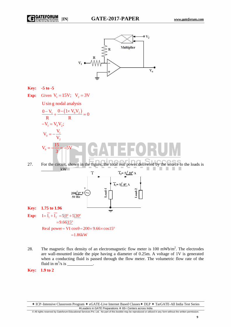
26. The two-input voltage multiplier, shown in the figure, has a scaling factor of 1 and produces
voltage output. If 1V 15V and 2V 3V, the value of V0 in volt is _________.
|IN| GATE-2017-PAPER www.gateforum.com
ICP–Intensive Classroom Program eGATE-Live Internet Based Classes DLP TarGATE-All India Test Series Leaders in GATE Preparations 65+ Centers across India
© All rights reserved by Gateforum Educational Services Pvt. Ltd. No part of this booklet may be reproduced or utilized in any form without the written permission.
9
Key: -5 to -5
Exp: Given 1 2V 15V; V 3V
0 21
1 0 2
10
2
0
Usin g nodal analysis
0 1 V V0 V0
R R
V V V ;
VV
V
15V 5V
3
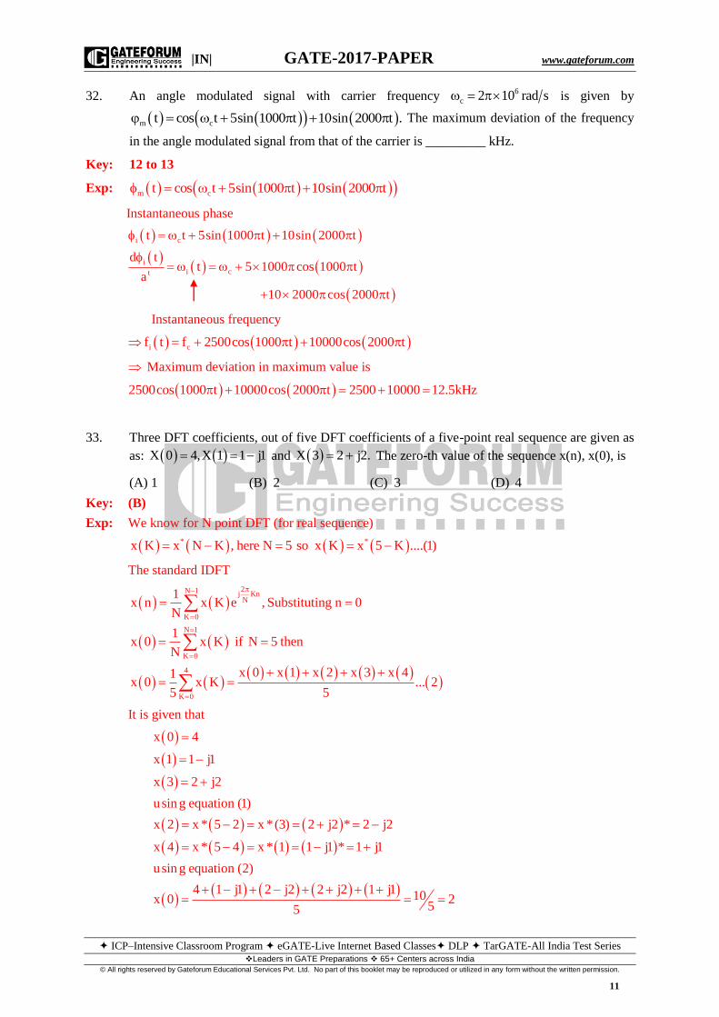
27. For the circuit, shown in the figure, the total real power delivered by the source to the loads is
_________kW
Key: 1.75 to 1.96
Exp: 1 2I I I 5 0 5 30
9.6615
Real power VI cos 200 9.66 cos15
1.86kW
28. The magnetic flux density of an electromagnetic flow meter is 100 mWb/m2. The electrodes
are wall-mounted inside the pipe having a diameter of 0.25m. A voltage of 1V is generated
when a conducting fluid is passed through the flow meter. The volumetric flow rate of the
fluid in m3/s is ____________.
Key: 1.9 to 2

|IN| GATE-2017-PAPER www.gateforum.com
ICP–Intensive Classroom Program eGATE-Live Internet Based Classes DLP TarGATE-All India Test Series Leaders in GATE Preparations 65+ Centers across India
© All rights reserved by Gateforum Educational Services Pvt. Ltd. No part of this booklet may be reproduced or utilized in any form without the written permission.
10
29. In the circuit, shown in the figure, the MOSFET is operating
in the saturation zone. The characteristics of the MOSFET is
given by 2
D GS
1I V 1 mA,
2 where VGS is in V. If
sV 5V, then the value of RS in k is _________.
Key: 9.9 to 10.1
Exp: Given
2
s D GS
1V 5V; I V 1 mA
2
G
GS G S
15 7V 7V;
15
V V V 7 5 2V
2
D
SS 2
D
1I 2 1 0.5mA
2
V 5R 10k
I 0.5 10
30. The hot junction of a bare thermocouple, initially at room temperature (30oC), is suddenly
dipped in molten metal at t = 0s. The cold junction is kept at room temperature. The
thermocouple can be modeled as a first-order instrument with a time constant of 1.0s and a
static sensitivity of o10 V C. If the voltage, measured across the thermocouple indicates 10.0
mV at t = 1.0s, then the temperature of the molten metal in oC is __________.
Key: 1605 to 1618
31. A series R-L-C circuit is excited with an a.c. voltage source. The quality factor (Q) of the
circuit is given as Q 30. The amplitude of current in ampere at upper half-power frequency
will be __________.
Key: 6 to 7
Exp:
3
6
1 LQ
R C
1 L 1 10 10 5R
Q C 30 4 10 3
5 2at upper half power frequency z 2 R
3
V 15I 3 6.36A
Z 5 2
|IN| GATE-2017-PAPER www.gateforum.com
ICP–Intensive Classroom Program eGATE-Live Internet Based Classes DLP TarGATE-All India Test Series Leaders in GATE Preparations 65+ Centers across India
© All rights reserved by Gateforum Educational Services Pvt. Ltd. No part of this booklet may be reproduced or utilized in any form without the written permission.
11
32. An angle modulated signal with carrier frequency 6
c 2 10 rad s is given by
m ct cos t 5sin 1000 t 10sin 2000 t . The maximum deviation of the frequency
in the angle modulated signal from that of the carrier is _________ kHz.
Key: 12 to 13
Exp: m ct cos t 5sin 1000 t 10sin 2000 t
Instantaneous phase
i c
i
i ct
t t 5sin 1000 t 10sin 2000 t
d tt 5 1000 cos 1000 t
a
10 2000 cos 2000 t
Instantaneous frequency
i cf t f 2500cos 1000 t 10000cos 2000 t
Maximum deviation in maximum value is
2500cos 1000 t 10000cos 2000 t 2500 10000 12.5kHz
33. Three DFT coefficients, out of five DFT coefficients of a five-point real sequence are given as
as: X 0 4,X 1 1 j1 and X 3 2 j2. The zero-th value of the sequence x(n), x(0), is
(A) 1 (B) 2 (C) 3 (D) 4
Key: (B)
Exp: We know for N point DFT (for real sequence)
* *x K x N K , here N 5 so x K x 5 K ....(1)
The standard IDFT
2N 1 j KnN
K 0
N 1
K 0
4
K 0
1x n x K e , Substituting n 0
N
1x 0 x K if N 5 then
N
x 0 x 1 x 2 x 3 x 41x 0 x K ... 2
5 5
It is given that
x 0 4
x 1 1 j1
x 3 2 j2
usin g equation (1)
x 2 x * 5 2 x *(3) 2 j2 * 2 j2
x 4 x * 5 4 x * 1 1 j1 * 1 j1
usin g equation (2)
4 1 j1 2 j2 2 j2 1 j110x 0 2
55
|IN| GATE-2017-PAPER www.gateforum.com
ICP–Intensive Classroom Program eGATE-Live Internet Based Classes DLP TarGATE-All India Test Series Leaders in GATE Preparations 65+ Centers across India
© All rights reserved by Gateforum Educational Services Pvt. Ltd. No part of this booklet may be reproduced or utilized in any form without the written permission.
12
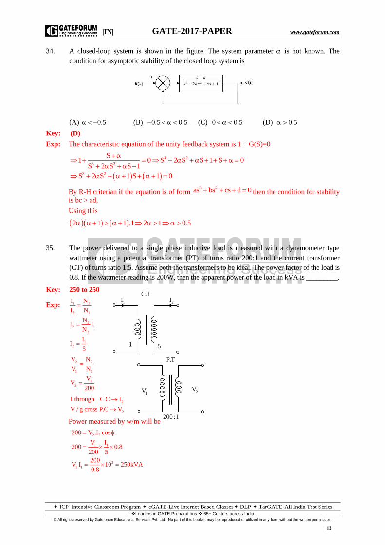
34. A closed-loop system is shown in the figure. The system parameter is not known. The
condition for asymptotic stability of the closed loop system is
(A) 0.5 (B) 0.5 0.5 (C) 0 0.5 (D) 0.5
Key: (D)
Exp: The characteristic equation of the unity feedback system is 1 + G(S)=0
3 2
3 2
3 2
S1 0 S 2 S S 1 S 0
S 2 S S 1
S 2 S 1 S 1 0
By R-H criterian if the equation is of form 3 2as bs cs d 0 then the condition for stability
is bc > ad,
Using this
2 1 1 .1 2 1 0.5
35. The power delivered to a single phase inductive load is measured with a dynamometer type
wattmeter using a potential transformer (PT) of turns ratio 200:1 and the current transformer
(CT) of turns ratio 1:5. Assume both the transformers to be ideal. The power factor of the load is
0.8. If the wattmeter reading is 200W, then the apparent power of the load in kVA is _________.
Key: 250 to 250
Exp: 1 2
2 1
1
2 1
2
1
2
I N
I N
NI I
N
II
5
2 2
1 1
1
2
V N
V N
VV
200
2
2
I through C.C I
V / g cross P.C V
Power measured by w/m will be
2 2
1 1
3
1 1
200 V .I cos
V I200 0.8
200 5
200V I 10 250kVA
0.8
C.T
2I1I
1 5
P.T
200 :1
1V 2V
|IN| GATE-2017-PAPER www.gateforum.com
ICP–Intensive Classroom Program eGATE-Live Internet Based Classes DLP TarGATE-All India Test Series Leaders in GATE Preparations 65+ Centers across India
© All rights reserved by Gateforum Educational Services Pvt. Ltd. No part of this booklet may be reproduced or utilized in any form without the written permission.
13
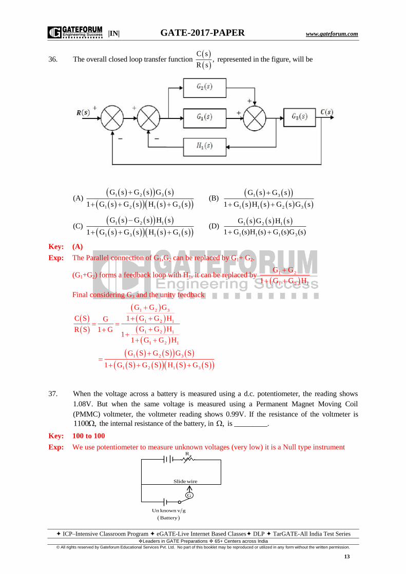
36. The overall closed loop transfer function
C s,
R s represented in the figure, will be
(A)
1 2 3
1 2 1 3
G s G s G s
1 G s G s H s G s
(B)
1 3
1 1 2 3
G s G s
1 G s H s G s G s
(C)
1 2 1
1 3 1 1
G s G s H s
1 G s G s H s G s
(D)
1 2 1
1 1 1 3
G s G s H s
1 G (s)H (s) G (s)G (s)
Key: (A)
Exp: The Parallel connection of G1,G2 can be replaced by G1+ G2.
(G1+G2) forms a feedback loop with H1, it can be replaced by
1 2
1 2 1
G G
1 G G H
Final considering G3 and the unity feedback
1 2 3
1 2 1
1 2 1
1 2 1
1 2 3
1 2 1 3
G G G
C S 1 G G HG
G G HR S 1 G1
1 G G H
G S G S G S
1 G S G S H S G S
37. When the voltage across a battery is measured using a d.c. potentiometer, the reading shows
1.08V. But when the same voltage is measured using a Permanent Magnet Moving Coil
(PMMC) voltmeter, the voltmeter reading shows 0.99V. If the resistance of the voltmeter is
1100 , the internal resistance of the battery, in , is _________.
Key: 100 to 100
Exp: We use potentiometer to measure unknown voltages (very low) it is a Null type instrument
G
Slidewire
rR
Un known v g
Battery
|IN| GATE-2017-PAPER www.gateforum.com
ICP–Intensive Classroom Program eGATE-Live Internet Based Classes DLP TarGATE-All India Test Series Leaders in GATE Preparations 65+ Centers across India
© All rights reserved by Gateforum Educational Services Pvt. Ltd. No part of this booklet may be reproduced or utilized in any form without the written permission.
14
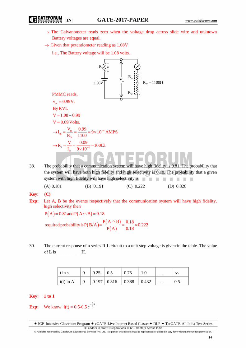
The Galvanometer reads zero when the voltage drop across slide wire and unknown
Battery voltages are equal.
Given that potentiometer reading as 1.08V
i.e., The Battery voltage will be 1.08 volts.
PMMC reads,
m
4mm
V
i 4
m
v 0.99V.
ByKVL
V 1.08 0.99
V 0.09Volts.
V 0.99I 9 10 AMPS.
R 1100
V 0.09R 100 .
I 9 10
38. The probability that a communication system will have high fidelity is 0.81. The probability that
the system will have both high fidelity and high selectivity is 0.18. The probability that a given
system with high fidelity will have high selectivity is
(A) 0.181 (B) 0.191 (C) 0.222 (D) 0.826
Key: (C)
Exp: Let A, B be the events respectively that the communication system will have high fidelity,
high selectivity then
P A 0.81andP A B 0.18
P A B 0.18requiredprobabilityisP B A 0.222
P A 0.18
39. The current response of a series R-L circuit to a unit step voltage is given in the table. The value
of L is ___________H.
Key: 1 to 1
Exp: We know i(t) = 0.5-0.5R
tLe
t in s 0 0.25 0.5 0.75 1.0 …
t(t) in A 0 0.197 0.316 0.388 0.432 … 0.5
iR
1.08V
v
mVmR
seR
VR 1100

|IN| GATE-2017-PAPER www.gateforum.com
ICP–Intensive Classroom Program eGATE-Live Internet Based Classes DLP TarGATE-All India Test Series Leaders in GATE Preparations 65+ Centers across India
© All rights reserved by Gateforum Educational Services Pvt. Ltd. No part of this booklet may be reproduced or utilized in any form without the written permission.
15
R0.25
L
V tat t , i t 0.5
R
1R 2
0.5
at t 0.25
R R 20.197 0.5 0.5e 2 L 1H
L 2 2
40. A resistance temperature detector (RTD) is
connected to a circuit, as shown in the figure,
Assume the op-amp to be ideal. If oV 2.0V,
then the value of x is __________.
Key: 0.19 to 0.21
Exp: At the inverting terminal of the op-amp
i.e., at V
By virtual ground t
V V 0
o12 0 V 0 12 00
R 1 x R R
12 2 12 1210 12 10 1 x x 1.2 1 0.2
R 1 x R R 1 x
41. The circuit of a Schmitt trigger is shown in the figure. The zener-diode combination maintains
the output between 7V. The width of the hysteresis band is _________V.
Key: 0.6 to 0.7
Exp: When zener diode combination maintains output of 7V
UTP
LTP
UTP LTP
7 0.5V 0.333V
10.5
7 0.5V 0.333V
10.5
Width of hysteresisband V V 0.333 0.333 0.666V

|IN| GATE-2017-PAPER www.gateforum.com
ICP–Intensive Classroom Program eGATE-Live Internet Based Classes DLP TarGATE-All India Test Series Leaders in GATE Preparations 65+ Centers across India
© All rights reserved by Gateforum Educational Services Pvt. Ltd. No part of this booklet may be reproduced or utilized in any form without the written permission.
16
42. The loop transfer function of a closed-loop system is given by
K s 6G s H s .
s s 2
The
breakaway point of the root-loci will be ____________.
Key: –1.2 to -1.0
Exp: To obtain the Break point first of all we have to arrange K intevms of GH, then the roots of
dk0
ds gives break point
2 22
2
2 2 2
2
1 S S 2K S 6GH K
S S 2 S 6
d dS 6 S 25 S 25 S 6
S 25 dk dS dSKS 6 ds S 6
0 S 6 2S 2 S 25 2S 2S 12S 12 S 25 0
S 12S 12 0 S 1.1, 10.83
To decide which among the two root is Breakaway draw the pole zero plot & mark real axis
branch.
So break away point be in 0 to -2 so break away point is -1.1.
43 The unbalanced voltage of the Wheatstone bridge, shown in the figure, is measured using
digital voltmeter having infinite input impedance and a resolution of 0.1mV. If R 1000 ,
then the minimum value of R in to create a detectable unbalanced voltage is _________.
Key: 0.17 to 0.23
Exp:
x
x
R
1k RV 2 1 ByVoltagedivision Rule.
2k R
V 1.0001volts 2 ByKVL
1.0001 1k R
2 2k R.
Bysolvingaboveequation,weget 0.2
6 2

|IN| GATE-2017-PAPER www.gateforum.com
ICP–Intensive Classroom Program eGATE-Live Internet Based Classes DLP TarGATE-All India Test Series Leaders in GATE Preparations 65+ Centers across India
© All rights reserved by Gateforum Educational Services Pvt. Ltd. No part of this booklet may be reproduced or utilized in any form without the written permission.
17
44. In the circuit diagram, shown in the figure, S1 was closed and S2 was open for a very long
time. At t = 0, S1 is opened and S2 is closed. The voltage across the capacitor, in volt, at t = 5
s is ___________.
Key: 1.43 to 1.63
Exp:
c
C
at t 0
V 0 1V
at t
2V 3 2V
3
6
6
6
6
eq eq
t
C C C C
t3
20 10
5 103
20 10
C
2 20R C 10 10 s
3 3
V t V V 0 V e
2 e
V 5 s 2 e 1.527V
45. The block diagram of a closed-loop control system is shown in the figure. The values of k and
kp are such that the system has a damping ratio of 0.8 and an undamped natural frequency n
of 4 rad/s respectively. The value of kp will be ___________.
Key: 0.32 to 0.4
Exp: 1+GH=0 represent the characteristic equation of the close loop –ve feed back system
P
P
2 2
P P
K 1 K S1 0 S S 1 K 1 K S 0
S S 1
S S K KK S 0 S 1 KK S K 0
Comparing with standard 2nd
order equation
2 2 2 2
n n nS 2 S 0 K 4 K K 16
Using K=16, the characteristic equation becomes
2
1V CV 0
3V
CV 0
2
1

|IN| GATE-2017-PAPER www.gateforum.com
ICP–Intensive Classroom Program eGATE-Live Internet Based Classes DLP TarGATE-All India Test Series Leaders in GATE Preparations 65+ Centers across India
© All rights reserved by Gateforum Educational Services Pvt. Ltd. No part of this booklet may be reproduced or utilized in any form without the written permission.
18
2
P n P
nP
S 1 16K S 16 0 2 1 16K
2 0.8 4 12 1K
16 16
270.3375
80
46. Assuming the op-amp shown in the figure to be ideal, the frequency at which the magnitude of
Vo will be 95% of the magnitude of Vin is ____________kHz.
Key: 2.9 to 3
Exp:
i ix 3 9
i ix 4 4
2 i i0 x 4 4
1
0 i
V VV
1 RCS 1 10 10 10 10 S
V VV
1 j10 2 f 1 j6.28 10 f
R V 2VV 1 V 1 1
R 1 j6.28 10 f 1 j6.28 10 f
when V 0.95V
i
i2
4
2V0.95V
1 6.28 10 f
2
4 21 6.28 10 f 2.105
0.95
2
4
4
4
1 6.28 10 f 4.431
6.28 10 f 3.431
3.431f
6.28 10
2.949kHz
|IN| GATE-2017-PAPER www.gateforum.com
ICP–Intensive Classroom Program eGATE-Live Internet Based Classes DLP TarGATE-All India Test Series Leaders in GATE Preparations 65+ Centers across India
© All rights reserved by Gateforum Educational Services Pvt. Ltd. No part of this booklet may be reproduced or utilized in any form without the written permission.
19
47. The following table lists an nth order polynomial n n 1
n n 1 1 0f x a x a x a x a
and the
forward differences evaluated at equally spaced values of x. The order of the polynomial is
x f(x) f 2f 3f
-0.4 1.7648 -0.2965 0.089 -0.03
-0.3 1.4683 -0.2075 0.059 -0.0228
-0.2 1.2608 -0.1485 0.0362 -0.0156
-0.1 1.1123 -0.1123 0.0206 -0.0084
0 1 -0.0917 0.0122 -0.0012
0.1 0.9083 -0.0795 0.011 0.006
0.2 0.8288 -0.0685 0.017 0.0132
(A) 1 (B) 2 (C) 3 (D) 4
Key: (D)
Exp: Clearly the entries in the fourth forward difference 4i.e. f areallsamewhichis 0.0072
The order of the polynomial is 4.
48. Consider two discrete-time signals:
1x n 1,1 and 2x n 1,2 , for n 0.1.
The Z-transform of the convoluted sequence 1 2x n x n * x n is
(A) 1 21 2z 3z (B) 2z 3z 2
(C) 1 21 3z 2z (D) 2 3 4z 3z 2z
Key: (C)
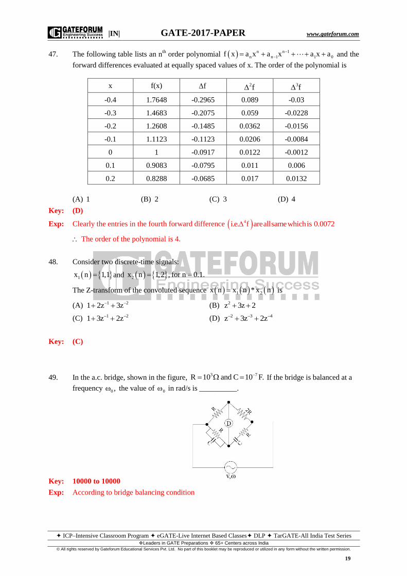
49. In the a.c. bridge, shown in the figure, 3 7R 10 and C 10 F. If the bridge is balanced at a
frequency 0 , the value of 0 in rad/s is __________.
Key: 10000 to 10000
Exp: According to bridge balancing condition
|IN| GATE-2017-PAPER www.gateforum.com
ICP–Intensive Classroom Program eGATE-Live Internet Based Classes DLP TarGATE-All India Test Series Leaders in GATE Preparations 65+ Centers across India
© All rights reserved by Gateforum Educational Services Pvt. Ltd. No part of this booklet may be reproduced or utilized in any form without the written permission.
20
1R
1 j CR R 2R
1j CR
j C
2
2 2
2 2
2 3 2 2 2
3 2 2 2
2 2 3
2 2
2 2 2
4
3 7 4
R RR 2R
j C j CR 1
R j C R 2R
j C j CR 1
R j C R j CR 1 2R j C
j C R R j C j CR R 2R j C
j C j CR R R 2R R
C R R
1 1C
R R C
1 1 110
RC 10 10 10
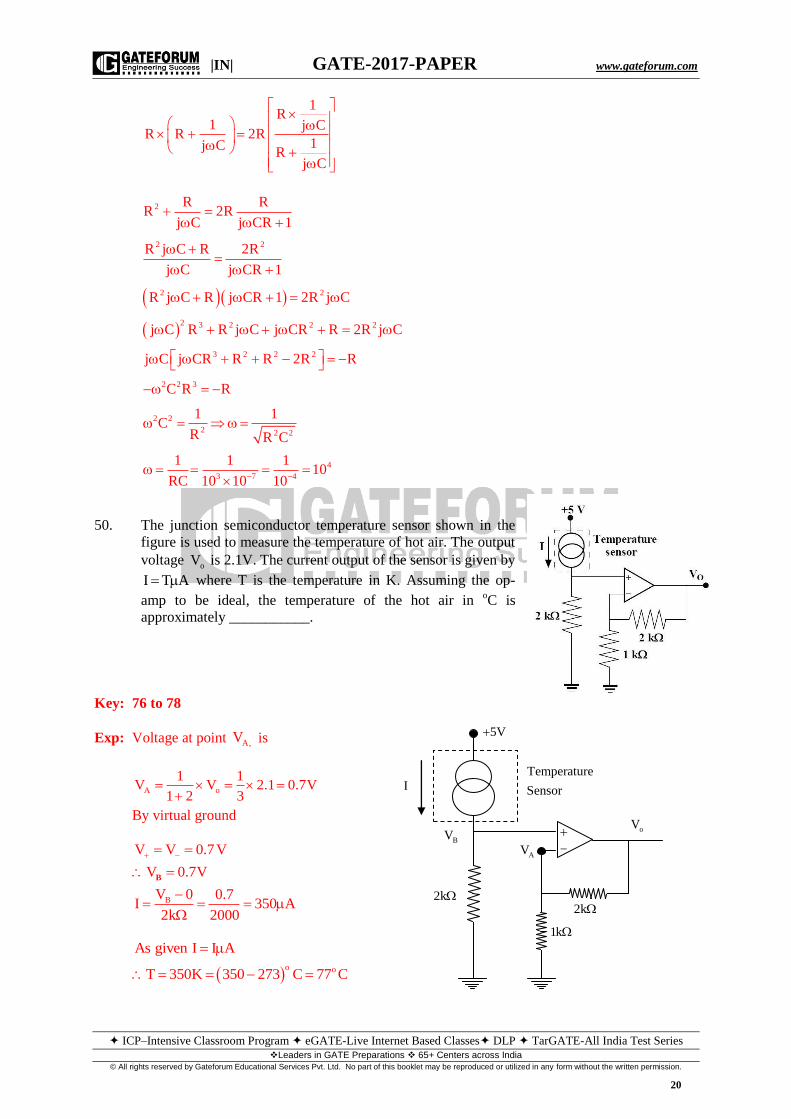
50. The junction semiconductor temperature sensor shown in the
figure is used to measure the temperature of hot air. The output
voltage oV is 2.1V. The current output of the sensor is given by
I T A where T is the temperature in K. Assuming the op-
amp to be ideal, the temperature of the hot air in oC is
approximately ___________.
Key: 76 to 78
Exp: Voltage at point A,V is
A o
1 1V V 2.1 0.7V
1 2 3
By virtual ground
B
V V 0.7V
V 0.7V
V 0 0.7I 350 A
2k 2000
B
o o
I I A
T 350K 350
As given
273 C 77 C
I
5V
BV
AV
oV
2k
1k
2k
Temperature
Sensor

|IN| GATE-2017-PAPER www.gateforum.com
ICP–Intensive Classroom Program eGATE-Live Internet Based Classes DLP TarGATE-All India Test Series Leaders in GATE Preparations 65+ Centers across India
© All rights reserved by Gateforum Educational Services Pvt. Ltd. No part of this booklet may be reproduced or utilized in any form without the written permission.
21
51. In a sinusoidal amplitude modulation scheme (with carrier) the modulated signal is given by
m c m cA t 100cos t 50cos t cos t , where c is the carrier frequency and
m is
the modulation frequency. The power carried by the sidebands in % of total power is
__________%
Key: 11 to 11.2
Exp: Given amplitude modulated signal
m c m c
c c m c m
A t 100cos t 50cos t cos t
100cos t 25cos t 25cos
2 22
C SB
25 25100P P
2 2 2
5000 625
Total power = 5625
Power carried by the side bands in % of total power625
11.11%5625
52. The angle between two vectors T
1x 2 6 14 and T
2x 12 8 16 in radian is
_________.
Key: 0.65 to 0.8
Exp: 2 12 6 8 14 16 248
cos4 36 196 144 64 256 236 464
620.75
59 116
0.72 radians
53 Quantum efficiency of a photodiode (ratio between the number of liberated electrons and the
number of incident photons) is 0.75 at 830 nm. Given Plank’s constant 34h 6.624 10 J, the
charge of an electron 19e 1.6 10 C and the velocity of light in the photodiode 8
mC 2 10 m s. For an incident optical power of 100 W at 830 nm, the photocurrent in A
is ___________.
Key: 74.5 to 75.5
Exp: 9
9 4
34 8
0.75 1.6 10830 10 7518.11 10
6.624Responsi
10vity R e
2 10
P
o
4 6 8 6
P o
INow R
P
I R P 7518.11 10 100 10 7518.11 10 75.18 10 A 75.18 A
Carrier Side Branch

|IN| GATE-2017-PAPER www.gateforum.com
ICP–Intensive Classroom Program eGATE-Live Internet Based Classes DLP TarGATE-All India Test Series Leaders in GATE Preparations 65+ Centers across India
© All rights reserved by Gateforum Educational Services Pvt. Ltd. No part of this booklet may be reproduced or utilized in any form without the written permission.
22
54. The two inputs A and B are connected to an R-S latch via two AND gates as shown in the
figure. If A =1 and B = 0, the output QQ is
(A) 00 (B) 10 (C) 01 (D) 11
Key: (B)
Exp: It is similar to JKFF A = J, B = K
n 1
n
n
J K Q
0 0 Q
0 1 0
1 0 1
1 1 Q
A B
Previous
State
[Qn]
J K Next State
A. Q B. Q n 1Q
n 1Q
1 0 0 1 0 1 0
1 0 1 0 0 1(Previous
output) 0
55. The Laplace transform of a causal signal s 2
y t is Y s .s 6
The value of the signal y(t) at
t = 0.1 s is __________ unit.
Key: -2.4 to -2.0
Exp: S 2 S 6 4 S 6 4 4
Y S 1S 6 S 6 S 6 S 6 S 6
Taking inverse Laplace
6t
6 0.1 0.6 0.6
y t t e u t
y 0.1 0.1 4e u 0.1 0 4 e 1 4e 2.19

|IN| GATE-2017-PAPER www.gateforum.com
ICP–Intensive Classroom Program eGATE-Live Internet Based Classes DLP TarGATE-All India Test Series Leaders in GATE Preparations 65+ Centers across India
© All rights reserved by Gateforum Educational Services Pvt. Ltd. No part of this booklet may be reproduced or utilized in any form without the written permission.
23
General Aptitude
Q. No. 1 - 5 Carry One Mark Each
1. The event would have been successful if you ______ able to come.
(A) are (B) had been (C) have been (D) would have been
Key: B
2. Four cards lie on a table. Each card has a number printed on one side and a colour on the other.
The faces visible on the cards are 2, 3, red and blue.
Proposition: If a card has an even value on one side, then its opposite face is red.
The cards which MUST be turned over to verify the above proposition are
(A) 2, red (B) 2, 3, red (C) 2, blue (D) 2, red, blue
Key: C
Exp: To check even red, we must confirm that back of 2 is red and back of blue is an odd
number.
3. What is the value of x when
x 2 2x 416 3
81 144 ?25 5
(A) 1 (B) -1 (C) -2 (D) cannot be determined
Key: B
Exp:
x 2
2x 4
2x 4 2x 4 2x
4
16
2581 144
35
4 4 4 9481 144 . 81 144 x 133 3 3 16
4. There was no doubt that their work was thorough.
Which of the words below is closest in meaning to the underlined word above?
(A) Pretty (B) complete (C) sloppy (D) haphazard
Key: B
5. Two dice are thrown simultaneously. The probability that the product of the numbers
appearing on the top faces of the dice is a perfect square is
(A) 1/9 (B) 2/9 (C) 1/3 (D) 4/9
Key: B
Exp: Required probability=8
36
2
9

|IN| GATE-2017-PAPER www.gateforum.com
ICP–Intensive Classroom Program eGATE-Live Internet Based Classes DLP TarGATE-All India Test Series Leaders in GATE Preparations 65+ Centers across India
© All rights reserved by Gateforum Educational Services Pvt. Ltd. No part of this booklet may be reproduced or utilized in any form without the written permission.
24
Q. No. 6- 10 Carry Two Marks Each
6. Bhaichung was observing the pattern of people entering and leaving a car service centre. There
was a single window where customers were being served. He saw that people inevitably came
out of the centre in the order that they went in. However, the time they spent inside seemed to
vary a lot: some people came out in a matter of minutes while for others it took much longer.
From this, what can one conclude?
(A) The centre operates on a first-come-first-served basis, but with variable service times,
depending on specific customer needs.
(B) Customers were served in an arbitrary order, since they took varying amounts of time of
service completion in the centre.
(C) Since some people came out within a few minutes of entering the centre, the system is
likely to operate on a last-come-first-served basis.
(D) Entering the centre early ensured that one would have shorter service times and most
people attempted to do this.
Key: (A)
Exp: People coming out in the same order in which they enter indicates that the centre operates on a
first-come-first-serve basis.
7. The points in the graph below represent
the halts of a lift for durations of 1
minute, over a period of 1 hour.
Which of the following statements are
correct?
(i) The elevator never moves directly from any non-ground floor to another non-ground floor
over the one hour period
(ii) The elevator stays on the fourth floor for the longest duration over the one hour period
(A) Only i (B) Only ii (C) Both i and ii (D) Neither i nor ii
Key: (D)
Exp: (i) is incorrect as it moves directly
(ii) is incorrect as it stayed for maximum duration on ground floor.
8. A map show the elevations of Darjeeling, Gangtok, Kalimpong, Pelling, and Siliguri,
Kalimpong is at a lowest elevation than Gangtok. Pelling is at a lower elevation than Gangtok.
Pelling is at a higher elevation than Siliguri. Darjeeling is at a higher elevation than Gangtok.
Which of the following statements can be inferred from the paragraph above?
(i) Pelling is at a higher elevation than Kalimpong
(ii) Kalimpong is at a lower elevation than Darjeeling
(iii) Kalimpong is at a higher elevation than Siliguri
(iv) Siliguri is at a lower elevation than Gangtok
(A) Only ii (B) Only ii and iii (C) Only ii and iv (D) Only iii and iv

|IN| GATE-2017-PAPER www.gateforum.com
ICP–Intensive Classroom Program eGATE-Live Internet Based Classes DLP TarGATE-All India Test Series Leaders in GATE Preparations 65+ Centers across India
© All rights reserved by Gateforum Educational Services Pvt. Ltd. No part of this booklet may be reproduced or utilized in any form without the written permission.
25
Key: (C)
Exp: The given information is K<G, P<G, S<P and G<D
From these it can be inferred
S<P<G<D and also K<G
So K<D as well but no comparison between K and S (or) K and P is given.
9. P, Q, R, S, T and U are seated around a circular table. R is seated two places to the right of Q.
P is seated three places to the left of R. S is seated opposite U. If P and U now switch seats,
which of the following must necessarily be true?
(A) P is immediately to the right of R
(B) T is immediately to the left of P
(C) T is immediately to the left of P or P is immediately to the right of Q
(D) U is immediately to the right of R or P is immediately to the left of T
Key: (C)
Exp: Following two possibilities can be drawn
Given in question P and U interchange then new diagram can be drawn.
now only option (C) verifies.
10. Budhan covers a distance of 19 km in 2 hours by cycling one fourth of the time and walking
the rest. The next day he cycles (at the same speed as before) for half the time and walks the
rest (at the same speed as before) and covers 26 km in 2 hours. The speed in km/h at which
Budhan walks is
(A) 1 (B) 4 (C) 5 (D) 6
Key: (D)
Exp: Let cycling speed = c and walking speed = w
Given 1 3
c w 19 (i)2 2
c w 26 (ii)
On solving eq(i) and (ii), we get
w 6km / hr
T
R
S
Q
P
U
T
R
U
Q
P
S
T
R
S
Q
U
PT
R
P
Q
U
S