in-line ductfans - О & И Инженеринг ductfans vcr / vcr-t, rectangular ductfans...
TRANSCRIPT

2
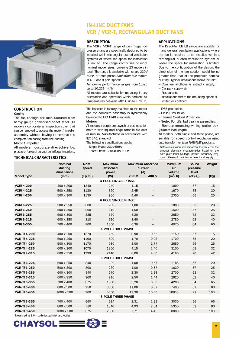
IN-LINE DUCT FANS
VCR / VCR-T, RECTANGULAR DUCT FANS
Nominal Nom. Maximum Maximum absorbed Maximum Sound Weightducting speed absorbed current air pressure
dimensions power (A) volume levelModel Type (mm) (r.p.m.) (W) 230 V 400 V (m3/h) (dB(A)) (kg)
4 POLE SINGLE PHASEVCR/4-200 400 x 200 1240 240 1,15 – 1090 57 15VCR/4-225 500 x 250 1130 520 2,45 – 1670 65 20VCR/4-250 500 x 300 1130 950 4,40 – 2350 66 25
6 POLE SINGLE PHASEVCR/6-225 500 x 250 800 200 1,00 – 1080 56 20VCR/6-250 500 x 300 800 310 1,50 – 1500 57 25VCR/6-285 600 x 300 825 660 3,20 – 2650 62 32VCR/6-315 600 x 350 810 710 3,40 – 2780 62 40VCR/6-355 700 x 400 800 1300 6,30 – 4070 64 60
4 POLE THREE PHASEVCR-T/4-200 400 x 200 1270 260 0,90 0,52 1150 57 15VCR-T/4-225 500 x 250 1160 500 1,70 0,98 1700 65 20VCR-T/4-250 500 x 300 1170 930 3,00 1,77 2650 66 25VCR-T/4-285 600 x 300 1070 1260 4,15 2,40 3100 68 32VCR-T/4-315 600 x 350 1390 2440 8,00 4,60 4160 70 42
6 POLE THREE PHASEVCR-T/6-225 500 x 250 840 220 1,00 0,57 1185 56 20VCR-T/6-250 500 x 300 800 280 1,00 0,57 1630 57 25VCR-T/6-285 600 x 300 840 670 2,30 1,33 2700 62 32VCR-T/6-315 600 x 350 900 710 2,50 1,44 2820 62 40VCR-T/6-355 700 x 400 875 1380 5,20 3,00 4200 64 65VCR-T/6-400 800 x 500 950 3000 11,00 6,37 7400 69 80VCR-T/6-450 1000 x 500 900 5350 17,30 10,00 10850 71 100
8 POLE THREE PHASEVCR-T/8-355 700 x 400 660 614 2,31 1,33 3030 56 65VCR-T/8-400 800 x 500 710 1340 4,93 2,84 5350 63 80VCR-T/8-450 1000 x 500 675 2380 7,71 4,45 8000 65 100
TECHNICAL CHARACTERISTICS
*Measured at 1.0m with ducted inlet and outlet.
DESCRIPTIONThe VCR / VCR-T range of centrifugal lowpressure fans are specifically designed to beinstalled within rectangular ducted ventilationsystems or where the space for installationis limited. The range comprises of eightnominal model sizes, covering 23 models intotal. The range is available with single 230V50Hz, or three phase 230/400V 50z motorsin 4, 6 and 8 pole speeds. Air volume performance ranges from 1,090up to 10,235 m3/hr. All models are suitable for mounting in anyorientation and operation within ambient airtemperatures between –40º C up to +70º C.
APPLICATIONSThe Direct-Air ILT/ILB range are suitable formany general ventilation applications wherethe fan is required to be installed within arectangular ducted ventilation system orwhere the space for installation is limited.Due to the configuration of the design, thedimension of the fan section would be nogreater than that of the proposed nominalducting. Typical installations would include:– Commercial offices air extract / supply.– Car park supply air– Restaurants– Installations where the mounting space is
limited or confined
CONSTRUCTIONCasingThe fan casings are manufactured fromheavy gauge galvanised sheet steel. Allmodels incorporate an inspection cover thatcan be removed to access the motor / impellerassembly without having to remove thecomplete fan casing from the ducting.Motor / ImpellerAll models incorporate direct-drive lowpressure forward curved centrifugal impellers.
The impeller is factory matched to the motorand the complete assembly is dynamicallybalanced to ISO 1940 standards.MotorsAll models incorporate asynchronous inductionmotors with squirrel cage rotor in die castaluminium. Manufactured in accordance withIEC 34-1 standard.The following specifications apply.– Single Phase 230V 50Hz.– Three Phase 230/400V 50Hz.
– IP55 protection.– Class F insulation.– Thermal Overload Protection.– Sealed For Life, ball bearing assemblies.– Remote mounting wir ing outlet box.(800mm lead length).All models, both single and three phase, aresuitable for speed control regulation usingauto-transformer type RMB-RMT products.Before installation, it is important to check that theproduct electrical characteristics listed on thedata plate label (voltage, power, frequency etc),match those of the intended electrical supply.
3
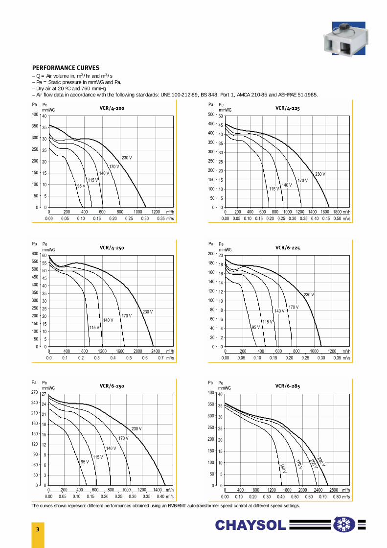
PERFORMANCE CURVES
– Q = Air volume in, m3/hr and m3/s– Pe = Static pressure in mmWG and Pa.– Dry air at 20 ºC and 760 mmHg.– Air flow data in accordance with the following standards: UNE 100-212-89, BS 848, Part 1, AMCA 210-85 and ASHRAE 51-1985.
VCR/4-200 VCR/4-225
VCR/4-250 VCR/6-225
VCR/6-250 VCR/6-285
The curves shown represent different performances obtained using an RMB-RMT auto-transformer speed control at different speed settings.
mmWG mmWG
mmWG mmWG
mmWG mmWG

4
PERFORMANCE CURVES
– Q = Air volume in, m3/hr and m3/s– Pe = Static pressure in mmWG and Pa.– Dry air at 20 ºC and 760 mmHg.– Air flow data in accordance with the following standards: UNE 100-212-89, BS 848, Part 1, AMCA 210-85 and ASHRAE 51-1985.
VCR/6-315 VCR/6-355
VCR-T/4-200 VCR-T/4-225
VCR-T/4-250 VCR-T/4-285
The curves shown represent different performances obtained using an RMB-RMT auto-transformer speed control at different speed settings.
mmWG mmWG
mmWG mmWG
mmWG mmWG

5
PERFORMANCE CURVES
– Q = Air volume in, m3/hr and m3/s– Pe = Static pressure in mmWG and Pa.– Dry air at 20 ºC and 760 mmHg.– Air flow data in accordance with the following standards: UNE 100-212-89, BS 848, Part 1, AMCA 210-85 and ASHRAE 51-1985.
VCR-T/4-315 VCR-T/6-225
VCR-T/6-250 VCR-T/6-285
VCR-T/6-315 VCR-T/6-355
The curves shown represent different performances obtained using an RMB-RMT auto-transformer speed control at different speed settings.
mmWG mmWG
mmWG mmWG
mmWG mmWG

6
PERFORMANCE CURVES
– Q = Air volume in, m3/hr and m3/s– Pe = Static pressure in mmWG and Pa.– Dry air at 20 ºC and 760 mmHg.– Air flow data in accordance with the following standards: UNE 100-212-89, BS 848, Part 1, AMCA 210-85 and ASHRAE 51-1985.
VCR-T/6-400 VCR-T/6-450
VCR-T/8-355 VCR-T/8-400
VCR-T/8-450
The curves shown represent different performances obtained using an RMB-RMT auto-transformer speed control at different speed settings.
mmWG mmWG
mmWG mmWG
mmWG
7
Model Type 125 250 500 1000 2000 4000 8000
4-200 63,0 64,0 62,0 57,5 50,0 43,5 33,0
4-225 69,5 73,0 70,5 64,0 58,0 50,0 40,0
6-225 63,0 66,0 63,5 57,0 51,0 43,0 33,0
4-250 72,5 71,0 70,0 65,5 60,5 53,0 44,0
6-250 63,5 62,0 61,5 56,5 51,5 44,0 35,0
4-285 73,5 74,0 73,5 66,0 62,0 53,0 43,0
6-285 67,5 68,0 67,5 60,5 56,0 47,5 37,5
4-315 77,5 74,0 74,5 72,0 70,0 61,5 49,0
6-315 68,0 64,0 65,0 62,0 60,5 52,0 39,5
6-355 70,5 69,0 70,0 63,5 61,5 51,0 41,0
8-355 62,0 60,0 61,5 55,0 52,5 42,5 32,5
6-400 75,0 74,0 74,0 70,0 66,5 57,5 46,0
8-400 69,0 67,5 68,0 63,5 60,5 49,5 40,0
6-450 78,0 76,5 76,0 71,5 69,5 58,0 48,5
8-450 72,0 70,5 70,0 65,5 63,5 52,0 42,5
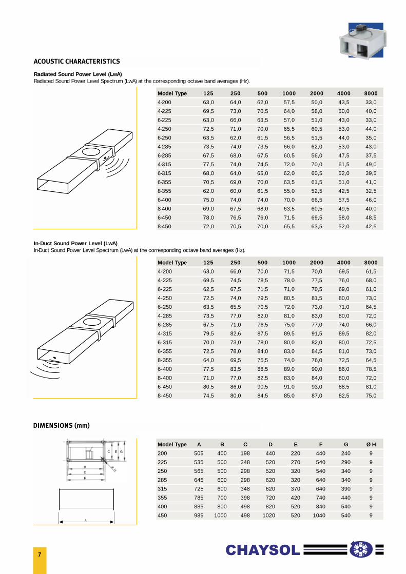
ACOUSTIC CHARACTERISTICS
A
Model Type A B C D E F G Ø H
200 505 400 198 440 220 440 240 9
225 535 500 248 520 270 540 290 9
250 565 500 298 520 320 540 340 9
285 645 600 298 620 320 640 340 9
315 725 600 348 620 370 640 390 9
355 785 700 398 720 420 740 440 9
400 885 800 498 820 520 840 540 9
450 985 10000 498 10200 520 10400 540 9
DIMENSIONS (mm)
Radiated Sound Power Level (LwA)Radiated Sound Power Level Spectrum (LwA) at the corresponding octave band averages (Hz).
Model Type 125 250 500 1000 2000 4000 8000
4-200 63,0 66,0 70,0 71,5 70,0 69,5 61,5
4-225 69,5 74,5 78,5 78,0 77,5 76,0 68,0
6-225 62,5 67,5 71,5 71,0 70,5 69,0 61,0
4-250 72,5 74,0 79,5 80,5 81,5 80,0 73,0
6-250 63,5 65,5 70,5 72,0 73,0 71,0 64,5
4-285 73,5 77,0 82,0 81,0 83,0 80,0 72,0
6-285 67,5 71,0 76,5 75,0 77,0 74,0 66,0
4-315 79,5 82,6 87,5 89,5 91,5 89,5 82,0
6-315 70,0 73,0 78,0 80,0 82,0 80,0 72,5
6-355 72,5 78,0 84,0 83,0 84,5 81,0 73,0
8-355 64,0 69,5 75,5 74,0 76,0 72,5 64,5
6-400 77,5 83,5 88,5 89,0 90,0 86,0 78,5
8-400 71,0 77,0 82,5 83,0 84,0 80,0 72,0
6-450 80,5 86,0 90,5 91,0 93,0 88,5 81,0
8-450 74,5 80,0 84,5 85,0 87,0 82,5 75,0
In-Duct Sound Power Level (LwA)In-Duct Sound Power Level Spectrum (LwA) at the corresponding octave band averages (Hz).
B
C E G
D
F
60
40
20
02 3 4 5 6 7 m/s
Air speed
∆p (Pa)
∆T (ºC) 50
40
30
20
10
0500 50004000300020001000 10000 m3/h
Air volume
63 kW63 kW
20 kW30 kW
50 kW16,5 kW
9 kW
8
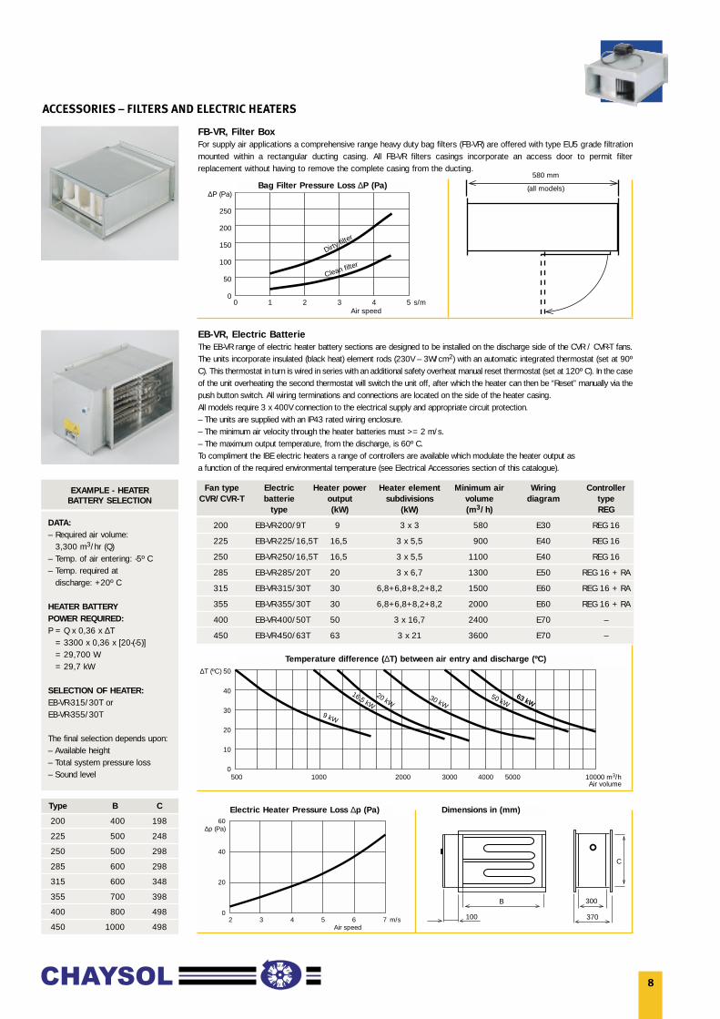
ACCESSORIES – FILTERS AND ELECTRIC HEATERS
FB-VR, Filter BoxFor supply air applications a comprehensive range heavy duty bag filters (FB-VR) are offered with type EU5 grade filtrationmounted within a rectangular ducting casing. All FB-VR filters casings incorporate an access door to permit filterreplacement without having to remove the complete casing from the ducting.
EB-VR, Electric BatterieThe EB-VR range of electric heater battery sections are designed to be installed on the discharge side of the CVR / CVR-T fans.The units incorporate insulated (black heat) element rods (230V – 3W/cm2) with an automatic integrated thermostat (set at 90ºC). This thermostat in turn is wired in series with an additional safety overheat manual reset thermostat (set at 120º C). In the caseof the unit overheating the second thermostat will switch the unit off, after which the heater can then be “Reset” manually via thepush button switch. All wiring terminations and connections are located on the side of the heater casing.All models require 3 x 400V connection to the electrical supply and appropriate circuit protection.– The units are supplied with an IP43 rated wiring enclosure.– The minimum air velocity through the heater batteries must >= 2 m/s.– The maximum output temperature, from the discharge, is 60º C.To compliment the IBE electric heaters a range of controllers are available which modulate the heater output asa function of the required environmental temperature (see Electrical Accessories section of this catalogue).
∆P (Pa)
250
200
150
100
50
00 1 2 3 4 5 s/m
Dirty filt
er
Clean filter
Air speed
580 mm
(all models)
Fan type Electric Heater power Heater element Minimum air Wiring ControllerCVR/CVR-T batterie output subdivisions volume diagram type
type (kW) (kW) (m3/h) REG
200 EB-VR-200/9T 9 3 x 3 580 E30 REG 16
225 EB-VR-225/16,5T 16,5 3 x 5,5 900 E40 REG 16
250 EB-VR-250/16,5T 16,5 3 x 5,5 1100 E40 REG 16
285 EB-VR-285/20T 20 3 x 6,7 1300 E50 REG 16 + RA
315 EB-VR-315/30T 30 6,8+6,8+8,2+8,2 1500 E60 REG 16 + RA
355 EB-VR-355/30T 30 6,8+6,8+8,2+8,2 2000 E60 REG 16 + RA
400 EB-VR-400/50T 50 3 x 16,7 2400 E70 –
450 EB-VR-450/63T 63 3 x 21 3600 E70 –
100
B 300
370
C
Dimensions in (mm)Electric Heater Pressure Loss ∆p (Pa)
Temperature difference (∆T) between air entry and discharge (ºC)
Bag Filter Pressure Loss ∆P (Pa)
EXAMPLE - HEATERBATTERY SELECTION
DATA:– Required air volume:
3,300 m3/hr (Q)– Temp. of air entering: -5º C– Temp. required at
discharge: +20º C
HEATER BATTERYPOWER REQUIRED:P = Q x 0,36 x ∆T
= 3300 x 0,36 x [20-(-5)]= 29,700 W= 29,7 kW
SELECTION OF HEATER:EB-VR-315/30T orEB-VR-355/30T
The final selection depends upon:– Available height– Total system pressure loss– Sound level
Type B C
200 400 198
225 500 248
250 500 298
285 600 298
315 600 348
355 700 398
400 800 498
450 1000 498
9
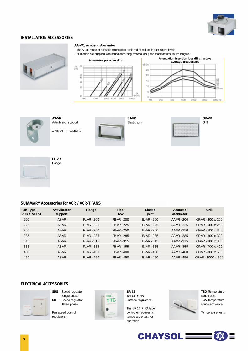
INSTALLATION ACCESSORIES
ELECTRICAL ACCESSORIES
AA-VR, Acoustic Atenuator– The AA-VR range of acoustic attenuators designed to reduce in-duct sound levels– All models are supplied with sound absorbing material (MO) and manufactured in 1m lengths.
Attenuation insertion loss dB at octave average frequenciesAttenuator pressure drop
AS-VRAntivibrator support
1 AS-VR = 4 supports
FL-VRFlange
EJ-VRElastic joint
GR-VRGrill
SRS - Speed regulator Single phase
SRT - Speed regulatorThree phase
Fan speed controlregulators.
BR 16BR 16 + RABatterie regulators
The BR 16 + RA typecontroller requires atemperature test foroperation.
TSD Temperaturesonde ductTSA Temperaturesonde ambiance
Temperature tests.
Fan Type Antivibrator Flange Filter Elastic Acoustic GrillVCR / VCR-T support box joint atenuator
200 AS-VR FL-VR - 200 FB-VR - 200 EJ-VR - 200 AA-VR - 200 GR-VR - 400 x 200
225 AS-VR FL-VR - 225 FB-VR - 225 EJ-VR - 225 AA-VR - 225 GR-VR - 500 x 250
250 AS-VR FL-VR - 250 FB-VR - 250 EJ-VR - 250 AA-VR - 250 GR-VR - 500 x 300
285 AS-VR FL-VR - 285 FB-VR - 285 EJ-VR - 285 AA-VR - 285 GR-VR - 600 x 300
315 AS-VR FL-VR - 315 FB-VR - 315 EJ-VR - 315 AA-VR - 315 GR-VR - 600 x 350
355 AS-VR FL-VR - 355 FB-VR - 355 EJ-VR - 355 AA-VR - 355 GR-VR - 700 x 400
400 AS-VR FL-VR - 400 FB-VR - 400 EJ-VR - 400 AA-VR - 400 GR-VR - 800 x 500
450 AS-VR FL-VR - 450 FB-VR - 450 EJ-VR - 450 AA-VR - 450 GR-VR - 1000 x 500
SUMMARY Accessories for VCR / VCR-T FANS

10
WIRING DIAGRAMS FOR TYPE MBE AND IBE ELECTRIC HEATER BATTERIES
WIRING DIAGRAM E20
ELECTRIC HEATER BATTERY TYPE: MBE–315/90TEB-VR–200/9T
A : HEATING ELEMENTSB : AUTO-RESET THERMAL PROTECTION STATC : MANUAL-RESET THERMAL PROTECTION STATD : BR 6 (Max. 6 kW 400V)E : SWITCHF : ELECTRICAL CONTACTORSG : ELECTRICAL LINE PROTECTIONH : TEMPERATURE TEST (type TSD or TSA, optional)
WIRING DIAGRAM E40
ELECTRIC HEATER BATTERY TYPE: EB-VR–225/16,5TEB-VR–250/16,5T
A : HEATING ELEMENTSB : AUTO-RESET THERMAL PROTECTION STATC : MANUAL-RESET THERMAL PROTECTION STATD : BR 6 (Max. 3,2 kW 230V)E : SWITCHF : ELECTRICAL CONTACTORSG : ELECTRICAL LINE PROTECTIONH : TEMPERATURE TEST (type TSD or TSA, optional)
WIRING DIAGRAM E50
ELECTRIC HEATER BATTERY TYPE: EB-VR–285/20T
A : HEATING ELEMENTSB : AUTO-RESET THERMAL PROTECTION STATC : MANUAL-RESET THERMAL PROTECTION STATD : BR 6 (Max. 16,5 kW 400V) + RA (Max. 70% of the load)E : SWITCHF : ELECTRICAL CONTACTORSG : ELECTRICAL LINE PROTECTIONH : TEMPERATURE TEST (type TSD or TSA, optional)
11
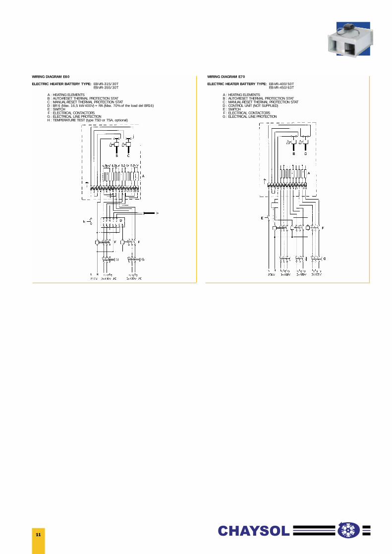
WIRING DIAGRAM E60
ELECTRIC HEATER BATTERY TYPE: EB-VR–315/30TEB-VR–355/30T
A : HEATING ELEMENTSB : AUTO-RESET THERMAL PROTECTION STATC : MANUAL-RESET THERMAL PROTECTION STATD : BR 6 (Max. 16,5 kW 400V) + RA (Max. 70% of the load del BR16)E : SWITCHF : ELECTRICAL CONTACTORSG : ELECTRICAL LINE PROTECTIONH : TEMPERATURE TEST (type TSD or TSA, optional)
WIRING DIAGRAM E70
ELECTRIC HEATER BATTERY TYPE: EB-VR–400/50TEB-VR–450/63T
A : HEATING ELEMENTSB : AUTO-RESET THERMAL PROTECTION STATC : MANUAL-RESET THERMAL PROTECTION STATD : CONTROL UNIT (NOT SUPPLIED)E : SWITCHF : ELECTRICAL CONTACTORSG : ELECTRICAL LINE PROTECTION