in-sight 7600/7800series visionsystem - mallenom · in-sight®7600/7800series visionsystem...
TRANSCRIPT
In-Sight® 7600/7800 SeriesVision SystemReference Guide
02/28/2017Version: 5.4.0.202

Legal NoticesThe software described in this document is furnished under license, and may be used or copied only in accordance withthe terms of such license and with the inclusion of the copyright notice shown on this page. Neither the software, thisdocument, nor any copies thereof may be provided to, or otherwise made available to, anyone other than the licensee.Title to, and ownership of, this software remains with Cognex Corporation or its licensor. Cognex Corporation assumesno responsibility for the use or reliability of its software on equipment that is not supplied by Cognex Corporation.Cognex Corporation makes no warranties, either express or implied, regarding the described software, itsmerchantability, non-infringement or its fitness for any particular purpose.
The information in this document is subject to change without notice and should not be construed as a commitment byCognex Corporation. Cognex Corporation is not responsible for any errors that may be present in either this document orthe associated software.
Companies, names, and data used in examples herein are fictitious unless otherwise noted. No part of this documentmay be reproduced or transmitted in any form or by any means, electronic or mechanical, for any purpose, nortransferred to any other media or language without the written permission of Cognex Corporation.
Copyright © 2017. Cognex Corporation. All Rights Reserved.
Portions of the hardware and software provided by Cognex may be covered by one or more U.S. and foreign patents, aswell as pending U.S. and foreign patents listed on the Cognex web site at: http://www.cognex.com/patents.
The following are registered trademarks of Cognex Corporation:
Cognex, 2DMAX, Advantage, AlignPlus, Assemblyplus, Check it with Checker, Checker, Cognex Vision for Industry,Cognex VSOC, CVL, DataMan, DisplayInspect, DVT, EasyBuilder, Hotbars, IDMax, In-Sight, Laser Killer, MVS-8000,OmniView, PatFind, PatFlex, PatInspect, PatMax, PatQuick, SensorView, SmartView, SmartAdvisor, SmartLearn,UltraLight, Vision Solutions, VisionPro, VisionView
The following are trademarks of Cognex Corporation:
The Cognex logo, 1DMax, 3D-Locate, 3DMax, BGAII, CheckPoint, Cognex VSoC, CVC-1000, FFD, iLearn, In-Sight(design insignia with cross-hairs), In-Sight 2000, InspectEdge, Inspection Designer, MVS, NotchMax, OCRMax,PatMax RedLine, ProofRead, SmartSync, ProfilePlus, SmartDisplay, SmartSystem, SMD4, VisiFlex, Xpand
Other product and company trademarks identified herein are the trademarks of their respective owners.
2
Legal Notices
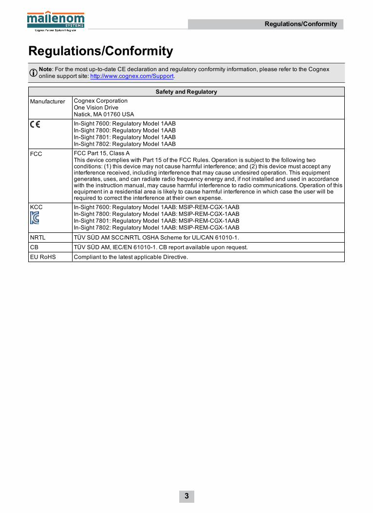
Regulations/ConformityNote: For the most up-to-date CE declaration and regulatory conformity information, please refer to the Cognexonline support site: http://www.cognex.com/Support.
Safety and RegulatoryManufacturer Cognex Corporation
One Vision DriveNatick, MA 01760 USAIn-Sight 7600: Regulatory Model 1AABIn-Sight 7800: Regulatory Model 1AABIn-Sight 7801: Regulatory Model 1AABIn-Sight 7802: Regulatory Model 1AAB
FCC FCC Part 15, Class AThis device complies with Part 15 of the FCC Rules. Operation is subject to the following twoconditions: (1) this device may not cause harmful interference; and (2) this device must accept anyinterference received, including interference that may cause undesired operation. This equipmentgenerates, uses, and can radiate radio frequency energy and, if not installed and used in accordancewith the instruction manual, may cause harmful interference to radio communications. Operation of thisequipment in a residential area is likely to cause harmful interference in which case the user will berequired to correct the interference at their own expense.
KCC In-Sight 7600: Regulatory Model 1AAB: MSIP-REM-CGX-1AABIn-Sight 7800: Regulatory Model 1AAB: MSIP-REM-CGX-1AABIn-Sight 7801: Regulatory Model 1AAB: MSIP-REM-CGX-1AABIn-Sight 7802: Regulatory Model 1AAB: MSIP-REM-CGX-1AAB
NRTL TÜV SÜD AM SCC/NRTL OSHA Scheme for UL/CAN 61010-1.
CB TÜV SÜD AM, IEC/EN 61010-1. CB report available upon request.
EU RoHS Compliant to the latest applicable Directive.
3
Regulations/Conformity

China RoHS
Hazardous Substances有害物质
Part Name部件名称
Lead (Pb)铅
Mercury (Hg)汞
Cadmium(Cd)镉
HexavalentChromium(Cr (VI))六价铬
Polybrominatedbiphenyls (PBB)多溴联苯
Polybrominateddiphenyl ethers (PBDE)多溴二苯醚
RegulatoryModel 1AAB
X O O O O O
This table is prepared in accordance with the provisions of SJ/T 11364.这个标签是根据SJ / T 11364 的规定准备的。
O: Indicates that said hazardous substance contained in all of the homogeneous materials for this part is below thelimit requirement of GB / T26572 - 2011.表示本部件所有均质材料中含有的有害物质低于GB / T26572 - 2011 的限量要求。
X: Indicates that said hazardous substance contained in at least one of the homogeneous materials used for this part isabove the limit requirement of GB / T26572 - 2011.表示用于本部件的至少一种均质材料中所含的危害物质超过GB / T26572 - 2011 的限制要求。
For European Community UsersCognex complies with Directive 2012/19/EU OF THE EUROPEAN PARLIAMENT AND OF THE COUNCIL of 4 July 2012on waste electrical and electronic equipment (WEEE).
This product has required the extraction and use of natural resources for its production. It may contain hazardoussubstances that could impact health and the environment, if not properly disposed.
In order to avoid the dissemination of those substances in our environment and to diminish the pressure on the naturalresources, we encourage you to use the appropriate take-back systems for product disposal. Those systems will reuse orrecycle most of the materials of the product you are disposing in a sound way.
The crossed out wheeled bin symbol informs you that the product should not be disposed of along with municipalwaste and invites you to use the appropriate separate take-back systems for product disposal.
If you need more information on the collection, reuse, and recycling systems, please contact your local or regional wasteadministration.
You may also contact your supplier for more information on the environmental performance of this product.
4
Regulations/Conformity
PrecautionsObserve these precautions when installing the Cognex product, to reduce the risk of injury or equipment damage:
l The vision system is intended to be supplied by a UL or NRTL listed power supply with a 24VDC output rated forat least 2A continuous and a maximum short circuit current rating of less than 8A and a maximum power rating ofless than 100VA and marked Class 2 or Limited Power Source (LPS). Any other voltage creates a risk of fire orshock and can damage the components. Applicable national and local wiring standards and rules must befollowed.
l To reduce the risk of damage or malfunction due to over-voltage, line noise, electrostatic discharge (ESD), powersurges, or other irregularities in the power supply, route all cables and wires away from high-voltage powersources.
l Do not install Cognex products where they are directly exposed to environmental hazards such as excessiveheat, dust, moisture, humidity, impact, vibration, corrosive substances, flammable substances, or static electricity.
l Do not expose the image sensor to laser light; image sensors can be damaged by direct, or reflected, laser light.If your application requires the use of laser light that may strike the image sensor, a lens filter at thecorresponding laser's wavelength is recommended. Contact your local integrator or application engineer forsuggestions.
l Changes or modifications not expressly approved by the party responsible for regulatory compliance could voidthe user’s authority to operate the equipment.
l Service loops should be included with all cable connections.
l Cable shielding can be degraded or cables can be damaged or wear out more quickly if a service loop or bendradius is tighter than 10X the cable diameter. The bend radius must begin at least six inches from the connector.
l Class A Equipment (broadcasting and communication equipment for office work): Seller and user shall benotified that this equipment is suitable for electromagnetic equipment for office work (Class A) and can be usedoutside the home.
l This device should be used in accordance with the instructions in this manual.
l All specifications are for reference purpose only and may be changed without notice.
5
Precautions
Table of ContentsLegal Notices 2Regulations/Conformity 3China RoHS 4For European Community Users 4
Precautions 5Table of Contents 6Symbols 8Introduction 9Support 9Standard Components 9Accessories 10In-Sight Lenses, Lens Covers and Lights 10DataMan Lenses, Lens Covers and Lights 15External Lights 17Cables 18Mounting Brackets 19I/OModules 19
Connectors and Indicators 20
Installation 21Install the Lens and Lighting 21Install the C-Mount Lens and Lens Cover Accessory 21Install the C-Mount Lens and Illumination Accessory 23Install the Autofocus Accessory and Illumination Accessory 28Install the In-Sight S-Mount/M12Manual Focus Lens 33
Mount the Vision System 35Install theMounting Bracket (ISB-7000-7K) 36Install theMounting Bracket (ISB-7000-5K) 37
Working Distance and Field of View (S-Mount/M12 Lenses) 38Connect the External Light Cable (Optional) 40Connect the Ethernet Cable 40Connect the Breakout Cable 41Connect the CIO-MICRO I/OModule (Optional) 42Connect the CIO-1400 I/O ExpansionModule (Optional) 45Replace the SD Card (Optional) 47Replace the LED Ring Light (Optional) 48Replace theM12 Autofocus Lens (Optional) 52Remove the Illumination Accessory PCB 58
Specifications 60Vision System Specifications 60Acquisition Trigger 63General-Purpose Inputs 64High-SpeedOutputs 65High-SpeedOutput Wiring 66
External Light Cable 67
6
Table of Contents

Ethernet Cable 68Breakout Cable 69I/OModule Cable 70Vision System Dimensions 71Vision System Dimensions (with Standard Lens Cover) 72Vision System Dimensions (with Extended Lens Cover) 73Vision System Dimensions (with Illumination and Lens Cover) 74Mounting Bracket Dimensions (ISB-7000-7K) 75Mounting Bracket Dimensions (ISB-7000-5K) 76Vision System C-Mount Lens Clearance Dimensions 77
Cleaning/Maintenance 78Clean the Vision System Housing 78Clean the Vision System Image SensorWindow 78
7
Table of Contents

SymbolsThe following symbols indicate safety precautions and supplemental information.
WARNING: This symbol indicates the presence of a hazard that could result in death, serious personal injury orelectrical shock.
CAUTION: This symbol indicates the presence of a hazard that could result in property damage.
Note: Notes provide supplemental information about a subject.
Tip: Tips provide helpful suggestions and shortcuts that may not otherwise be apparent.
8
Symbols

IntroductionThe In-Sight® vision system is a compact, network-ready, stand-alone machine vision system used for automatedinspection, measurement, identification and robot guidance applications on the factory floor. All models can be easilyconfigured remotely over a network using an intuitive user interface.
SupportMany information resources are available to assist you in using the vision system:
l The In-Sight® Explorer Help and EasyBuilder Help files, provided with In-Sight Explorer software.
l On-demand training: http://www.cognex.com/on-demand-training.aspx.
l The In-Sight online support site: http://www.cognex.com/Support/InSight.
Standard ComponentsNote:
l Cables are sold separately.
l If any of the standard components appear to be missing or damaged, immediately contact your CognexAuthorized Service Provider (ASP) or Cognex Technical Support.
Component DescriptionVision System Provides image acquisition, vision processing, job storage, Ethernet connectivity and discrete I/O. The
vision system has an SD card pre-installed.
9
Introduction

AccessoriesThe following components can be purchased separately. For a complete list of options and accessories, contact yourlocal Cognex sales representative.
In-Sight Lenses, Lens Covers and LightsC-Mount Accessories
Note:l The following C-Mount lenses are supported with the vision system. If a different lens is used, the followingrestrictions apply. Refer to Vision System C-Mount Lens Clearance Dimensions on page 77 for moreinformation.
l Maximum thread length is 5.25 mm.
l At infinity focus, the back focal length of the lens cannot be greater than 6.5 mm in length unless theback of the lens is smaller than 14.75 mm diameter.
Standard and Extended C-Mount Lenses and Lens Covers
Note:l The following C-Mount lenses are supported with the vision system when using the standard lens cover(COV-7000-CMNT) or extended lens cover (COV-7000-CMNT-EX) accessories. If a different lens is used,the following restrictions apply:
l If using the standard lens cover accessory (COV-7000-CMNT), the maximum lens length is 41mmwith a bandpass filter, the maximum lens body diameter is 36.5mm and the maximum diameterincluding locking screws is 47mm.
l If using the extended lens cover accessory (COV-7000-CMNT-EX), the maximum lens length is62mm with a bandpass filter, the maximum lens body diameter is 36.5mm and the maximumdiameter including locking screws is 46.5mm.
CAUTION: If installing a standard or extended C-Mount lens, the illumination accessory (ISLM-7000-WHI) PCBshould not be installed to the vision system. Refer to Remove the Illumination Accessory PCB on page 58 for stepsto safely remove the PCB and avoid damage to the vision system.
16mm F11 fixed aperture lens (LEC-CFF16-F11)
16mm F16 fixed aperture lens (LEC-CFF16-F16)
25mm F11 fixed aperture lens (LEC-CFF25-F11)
25mm F16 fixed aperture lens (LEC-CFF25-F16)
35mm F11 fixed aperture lens (LEC-CFF35-F11)
35mm F16 fixed aperture lens (LEC-CFF35-F16)50mm F2-F22 aperture lens (LEC-59873)
Note: The extended lens cover accessory (COV-7000-CMNT-EX) is required for the50mm lens.
10
Introduction

9mm F1.4 aperture lens (LFC-9F1B)
12.5mm F1.4 aperture lens (LFC-12.5F)
16mm F1.4 aperture lens (LFC-16F1)
25mm F1.4 aperture lens (LFC-25F1)
35mm F1.6 aperture lens (LFC-35F1)50mm F1.4 aperture lens (LFC-50F1)
Note: The extended lens cover accessory (COV-7000-CMNT-EX) is required for the50mm lens.
Standard lens cover and lens cover adapter (COV-7000-CMNT)
Extended lens cover and lens cover adapter (COV-7000-CMNT-EX)
11
Introduction

Illumination Accessory C-Mount Lenses, Lens Covers and Lights
CAUTION: The following C-Mount lenses are supported with the illumination accessory (ISLM-7000-WHI). If usinga different C-Mount lens with the illumination accessory, it must be 29.5mm in diameter or smaller. Maximum lenslength is 38.5mm without a bandpass filter and 36mm with a bandpass filter. Larger lenses will irretrievably damagethe vision system.
9mm F1.4 aperture lens (LFC-9F1B)
12.5mm F1.4 aperture lens (LFC-12.5F)
16mm F1.4 aperture lens (LFC-16F1)
25mm F1.4 aperture lens (LFC-25F1)
35mm F1.6 aperture lens (LFC-35F1)50mm F1.4 aperture lens (LFC-50F1)
Illumination with white LED ring light, lens cover and hex wrench (ISLM-7000-WHI)
Clear illumination lens cover (COV-7000-CLR)
Polarized lens cover (COV-7000-PL-FULL)
Note: When installing the lens cover, pull the red tab to remove the protective film.
Red LED ring light (ISL-7000-RD), used with the illumination accessory (ISLM-7000-WHI)
IR LED ring light (ISL-7000-IR), used with the illumination accessory (ISLM-7000-WHI)
Blue LED ring light (ISL-7000-BL), used with the illumination accessory (ISLM-7000-WHI).
White LED ring light (ISL-7000-WHI), used with the illumination accessory (ISLM-7000-WHI)
Red bandpass filter (ISF-7000-RDBP605), used with the illumination accessory (ISLM-7000-WHI)
IR bandpass filter (ISF-7000-IRBP815), used with the illumination accessory (ISLM-7000-WHI)
Blue bandpass filter (ISF-7000-BLBP435), used with the illumination accessory (ISLM-7000-WHI)
12
Introduction
S-Mount/M12 Autofocus AccessoriesAutofocus module with 8mm lens (ISAF-7000-8mm)
6mm M12 lens (LM12-06-01)8mm M12 lens (LM12-08-01-F2.2)12mm M12 lens (LM12-12-01-F2.3)16mm M12 lens (LM12-16-01)
25mm M12 lens (LM12-25-01)
Illumination with white LED ring light, lens cover and hex wrench (ISLM-7000-WHI)
Clear illumination lens cover (COV-7000-CLR)
Polarized lens cover (COV-7000-PL-FULL)
Note: When installing the lens cover, pull the red tab to remove the protective film.
Red LED ring light (ISL-7000-RD), used with the illumination accessory (ISLM-7000-WHI)
IR LED ring light (ISL-7000-IR), used with the illumination accessory (ISLM-7000-WHI)
Blue LED ring light (ISL-7000-BL), used with the illumination accessory (ISLM-7000-WHI).
White LED ring light (ISL-7000-WHI), used with the illumination accessory (ISLM-7000-WHI)
Red bandpass filter (ISF-7000-RDBP605), used with the illumination accessory (ISLM-7000-WHI)
IR bandpass filter (ISF-7000-IRBP815), used with the illumination accessory (ISLM-7000-WHI)
Blue bandpass filter (ISF-7000-BLBP435), used with the illumination accessory (ISLM-7000-WHI)
13
Introduction

S-Mount/M12 Manual Focus Accessories
Note:l The DataMan clear lens cover accessory (DM300-CLCOV) is supported with In-Sight S-Mount/M12 manualfocus lenses and provides IP65 rating. For more information, refer to DataMan Lenses, Lens Covers andLights on page 15.
l The following S-Mount/M12 lenses are supported with the vision system. If a different lens is used, thefollowing restrictions apply:
l At infinity focus, the back focal length must be greater than 5.5mm.
l Close up, the back focal length of the lens cannot be greater than 13mm.
6mm M12 lens (LM12-06-01)8mm M12 lens (LM12-08-01-F2.2)12mm M12 lens (LM12-12-01-F2.3)16mm M12 lens (LM12-16-01)
25mm M12 lens (LM12-25-01)S-Mount/M12 adapter, lens locking cone and installation tool (ISLN-7000-SMNT)
Note: The S-Mount accessory kit (ISLN-7000-SMNT) is required when installing In-Sight S-Mount/M12 manual focus lenses.
14
Introduction

DataMan Lenses, Lens Covers and LightsThe following DataMan accessories are also supported with the In-Sight vision system for S-Mount/M12 manual focuslens configurations. DataMan lenses are only supported with DataMan lens covers and lights.
Note:l The following S-Mount/M12 lenses are supported with the vision system. If a different lens is used, thefollowing restrictions apply:
l At infinity focus, the back focal length must be greater than 5.5 mm.
l Close up, the back focal length of the lens cannot be greater than 10 mm.
10.3 mm M12 lens with locking (DM300-LENS-10) and 10.3 mm IR M12 lens with locking(DM300-LENS-10-IR)
16 mm M12 lens with locking (DM300-LENS-16)
25 mm M12 lens with lens spacer and hex wrench (DM300-LENS-25) (also requires Extensionkit)
Extension kit (DM300-EXT)
Clear lens cover (DM300-CLCOV)
Clear lens cover with white LED illumination (DM300-CLCOV-WHI)
Diffuse lens cover with red LED illumination (DM300-DLCOV-RE)
Diffuse lens cover with blue LED illumination (DM300-DLCOV-BL)
Diffuse lens cover with IR LED illumination (DM300-DLCOV-IR)
Polarized lens cover with red LED illumination (DM300-PLCOV-RE)
Diffuse lens cover, red illumination (assembled), ESD safe (DM300-DLCOV-RE-ESD)
15
Introduction

Polarized red LED high-powered integrated light, ESD safe (DM360-HPIL-RE-P)
Non-polarized red LED high-powered integrated light (DM360-HPIL-RE)
High Power IlluminationsRed narrow (DM30X-HPIA3-625)
Red wide (DM30X-HPIA3-625-W)
White narrow (DM30X-HPIA3-WHI)
White wide (DM30X-HPIA3-WHI-W)
Blue narrow (DM30X-HPIA3-470)
Blue wide (DM30X-HPIA3-470-W)
Infrared narrow (DM30X-HPIA3-IR)
Infrared wide (DM30X-HPIA3-IR-W)
Note:l If using the following Cognex high-power illumination lights with a DM30X-HPIA-xxx product ID:
l A spacer kit accessory (DMA-SPKIT-30X-00) is required when using the high power illuminationaccessory. When the spacer is used, the field of view will be limited for wide-angled lenses.
l A Fair-Rite ferrite (part number 0431167281) must be attached to the External Light cable to reduceemissions.
Red narrow (DM30X-HPIA-625)
Red wide (DM30X-HPIA-625-W)
Red narrow with polarizer (DM30X-HPIA-625P)
White narrow (DM30X-HPIA-WHI)
White wide (DM30X-HPIA-WHI-W)
Blue narrow (DM30X-HPIA-470)
Blue wide (DM30X-HPIA-470-W)
Infrared narrow (DM30X-HPIA-IR)
Infrared wide (DM30X-HPIA-IR-W)
16
Introduction

External Lights
Note:l External lights can be connected to the vision system's LIGHT connector using the External Light cable(CCB-M12LTF-xx). The vision system supports using either an external light or the illumination accessory(ISLM-7000-WHI), but does not support using both lighting devices simultaneously.
l If using a Cognex external light with an IVSL-ODDM-S75, IVSL-YLW2X-xxx, IVSL-YLW300-xxx or IVSL-LX520-xxx product ID, a Fair-Rite ferrite (part number 0431167281) must be attached to the External Lightcable to reduce emissions.
l If daisy-chaining multiple Cognex external lights with IVSL-YLW2X-xxx or IVSL-YLW300-xxx product IDs,the lights must be powered externally by a separate power supply. A Cognex control cable (CCB-FOV25-MAL-012) can be used to connect the vision system’s LIGHT connector to the external light and a Cognexpower cable (IVSL-5PM12-5) can be used to connect the light to the separate power supply. Only the powerand ground wires from the Cognex power cable (IVSL-5PM12-5) should be connected to the remote powersupply.
l If using a Cognex external light with an IVSL-LX520-xxx product ID, the lights must be powered externally bya separate power supply. A Cognex control cable (CCB-FOV25-MAL-012) can be used to connect the visionsystem’s LIGHT connector to the external light and a Cognex power cable (IVSL-5PM12-5) can be used toconnect the light to the separate power supply. Only the power and ground wires from the Cognex powercable (IVSL-5PM12-5) should be connected to the remote power supply. The following power cables mustnot be used with IVSL-LX520-xxx external lights: IVSL-5PM12-J300, IVSL-5PM12-J500, IVSL-5PM12-J1000, IVSL-5PM12-J2000.
Ring light (CLRR-R7030G1CLR)
Back light (CLRB-F100100G1)
Coaxial (DOAL) light (CLRO-K5050G1)
Spot light (CLRS-P14G1)
Dark-field light (CLRD-D120G1)
Brick light, narrow blue (IVSL-ODDM-S75-470)
Brick light, narrow red (IVSL-ODDM-S75-625)
Brick light, narrow white (IVSL-ODDM-S75-WHI)
17
Introduction

Bar light, wide red (IVSL-YLW2X-625)
Bar light, narrow red, linear polarizer (IVSL-YLW2X-625P)
Bar light, narrow infrared (IVSL-YLW2X-850)
Bar light, narrow blue (IVSL-YLW300-470)
Bar light, wide blue (IVSL-YLW300-470 W)
Bar light, narrow red (IVSL-YLW300-625)
Bar light, wide red (IVSL-YLW300-625 W)
Bar light, narrow white (IVSL-YLW300-WHI)
Bar light, wide white (IVSL-YLW300-WHI W)
Bar light, blue (IVSL-LX520-470)
Bar light, red (IVSL-LX520-625)
Bar light, linear polarizer (IVSL-LX520-LP)
CablesBreakout cable, M12-12, 5m (CCBL-05-01)
Breakout cable, M12-12 (CCBPWRIO- xx) (straight, xx specifies length: 5m, 10m,15m)
Ethernet M12 to RJ-45 cable (CCB-84901-2001-xx) (straight, xx specifies length: 2m,5m, 10m, 15m, 30m)
Ethernet M12 to RJ-45 cable (CCB-84901-2001-xxR) (angled, xx specifies length:2m, 5m, 10m, 15m, 30m)
External Light cable (CCB-M12LTF-xx) (xx specifies length: 0.5m, 1m, 2m, 5m)
External Light cable (IVSL-5PM12-J300, IVSL-5PM12-J500, IVSL-5PM12-J1000 andIVSL-5PM12-J2000)
I/O Module cable M12-12 to DB15 (CCB-PWRIO-MOD-xx) (xx specifies length: 2m,5m)
18
Introduction
Mounting BracketsMounting bracket with M3x4 socket head screws and hex wrench (ISB-7000-7K). Alsohas 1/4 - 20, M6 and flathead mounting holes. Mounting holes compatible withIn-Sight 7000 series vision systems.
Mounting bracket with Phillips flat head M3 screws and M4x4 screws (ISB-7000-5K).Mounting holes compatible with In-Sight 5000 series vision systems.
I/O ModulesIn-Sight CIO-MICRO I/O Module (CIO-MICRO-00)
In-Sight 1400 I/O Expansion Module (CIO-1400)
19
Introduction

Connectors and Indicators
Connector FunctionPWRConnector
Connects the Breakout cable, which provides connections to an external power supply, the acquisitiontrigger input, general-purpose inputs, high-speed outputs, and RS-232 serial communications. Formore information, refer to Breakout Cable on page 69. Alternately, this connector is used to attach theI/O Module cable to a compatible In-Sight I/O module, which adds general-purpose discrete I/O. Formore information, refer to I/O Module Cable on page 70.
LIGHTConnector
Connects the vision system to an external lighting device. For more information, refer to External LightControl Cable on page 1.
ENETConnector
Connects the Ethernet cable, which provides 10/100/1000 Ethernet connectivity. For more information,refer to Ethernet Cable on page 68.
Indicator FunctionFocus MetricLEDs
Indicates the image focus score (0 - 10) while in Live Video Mode withinIn-Sight Explorer.
TRIG Button Manually triggers an image acquisition when the vision system is either:
l Online within In-Sight Explorer and the AcquireImage function'sTrigger parameter is configured as Manual.
l Offline within In-Sight Explorer.
Power LED The green LED illuminates to indicate that the vision system is powered on.
SD Card StatusLED
l Off: SD card is not present.
l Green: SD card is present and it is safe to remove the SD card afterremoving power from the vision system.
l Yellow: The SD card is present, but it is not safe to remove it.
Pass/Fail LED andIndicator Ring
Green or red when active. User configurable.
Network LED The yellow LED flashes to indicate network activity.
Error LED Red when active. User configurable.
TUNE Button Used as an Event Trigger within In-Sight Explorer to force a cell containingan Event structure to run when the TUNE button is pressed.
20
Introduction
InstallationThis section describes the connection of the vision system to its standard components and accessories.
Note: Cables are sold separately.
CAUTION: All cable connectors are “keyed” to fit the connectors on the vision system; do not force the connectionsor damage may occur.
Install the Lens and LightingYou can choose between a variety of different C-Mount and S-Mount/M12 lenses and lens covers to install to the visionsystem. Refer to In-Sight Lenses, Lens Covers and Lights on page 10 and DataMan Lenses, Lens Covers and Lights onpage 15 for a complete list of options and accessories.
Install the C-Mount Lens and Lens Cover AccessoryComplete the following steps to install a standard or extended C-Mount lens with the standard lens cover (COV-7000-CMNT) or extended lens cover (COV-7000-CMNT-EX) accessories. For a list of supported accessories, refer to Standardand Extended C-Mount Lenses and Lens Covers on page 10.
CAUTION: If installing a standard or extended C-Mount lens, the illumination accessory (ISLM-7000-WHI) PCBshould not be installed to the vision system. Refer to Remove the Illumination Accessory PCB on page 58 for stepsto safely remove the PCB and avoid damage to the vision system.
1. Remove the rubber faceplate covering the image sensor window, if present.
2. Remove the protective film covering the threaded lens opening, if present.
3. Place the lens cover adapter on the faceplate of the vision system. Insert the four adapter screws and tighten; themaximum torque is 0.26 Nm (37.5 in-oz).
4. Thread the lens into the vision system.
21
Installation

5. Attach the standard lens cover (COV-7000-CMNT) or extended lens cover (COV-7000-CMNT-EX) to the visionsystem. Rotate the lens cover clockwise approximately seven degrees to lock it.
22
Installation

Install the C-Mount Lens and Illumination AccessoryComplete the following steps to install a C-Mount lens and the illumination accessory (ISLM-7000-WHI).
CAUTION:l Refer to Illumination Accessory C-Mount Lenses, Lens Covers and Lights on page 12 for lenses supportedwith the illumination accessory (ISLM-7000-WHI). If using a different C-Mount lens with the illuminationaccessory, it must be 29.5mm in diameter or smaller. Maximum lens length is 38.5mm without a bandpassfilter and 36mm with a bandpass filter. Larger lenses will irretrievably damage the vision system.
l Do not hot-plug the illumination accessory; verify the vision system is not receiving power when connectingor disconnecting the illumination accessory. Failure to remove power during this procedure may result indamage to the vision system and/or the lighting accessory.
l It is recommended the vision system be grounded, either by mounting the vision system to a fixture that iselectrically grounded or by attaching a wire from the vision system’s mounting fixture to frame ground orEarth ground. If a ground wire is used, it should be attached to one of the four mounting points on the backplate of the vision system; not to the mounting points on the front of the vision system.
l Tighten all of the illumination accessory screws in the following sequence.
1. Remove the rubber faceplate covering the image sensor window, if present.
2. Remove the protective film covering the threaded lens opening, if present.
3. Plug the PCB into the lighting connector on the vision system faceplate.
CAUTION: If uninstalling the PCB from the vision system, refer to Remove the Illumination Accessory PCBon page 58 for steps to safely remove the PCB and avoid damage to the vision system.
23
Installation

4. Place the spacer on top of the vision system with “TOP” oriented upward. Verify seating of the gasket on thebottom of the spacer. Insert the four M3 x 6mm screws and use a 2mm hex wrench to torque screws to 0.34 Nm (3in-lb).
5. Thread the lens into the vision system. Focusing of C-Mount lens prior to light housing installation is required.
Note: If installing the autofocus accessory (ISAF-7000-8mm), refer to Install the Autofocus Accessory andIllumination Accessory on page 28.
24
Installation

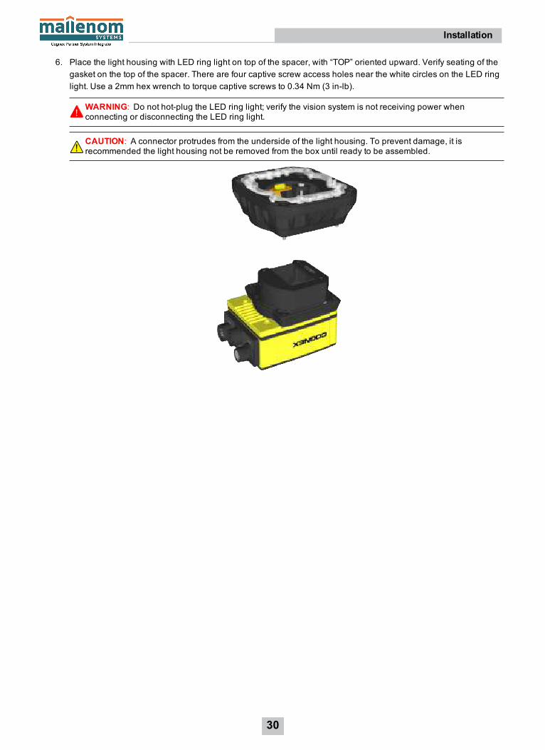
6. Place the light housing with LED ring light on top of the spacer, with “TOP” oriented upward. Verify seating of thegasket on the top of the spacer. There are four captive screw access holes near the white circles on the LED ringlight. Use a 2mm hex wrench to torque captive screws to 0.34 Nm (3 in-lb). If a different LED color is required,refer to Replace the LED Ring Light (Optional) on page 48.
WARNING: Do not hot-plug the LED ring light; verify the vision system is not receiving power whenconnecting or disconnecting the LED ring light.
CAUTION: A connector protrudes from the underside of the light housing. To prevent damage, it isrecommended the light housing not be removed from the box until ready to be assembled.
25
Installation

7. If using a bandpass filter, insert the filter in the light baffle so that it's held in place between the light baffle's filterretention tabs.
Tip: Wear gloves when installing the filter to prevent getting fingerprints on the surface of the filter.
Push the filter down and snap it into place. Ensure the filter retention tabs are flush with the top surface of thefilter.
8. The light baffle is keyed to fit the LED ring light structure and snaps into place with the keyed tabs sitting flushover each light housing captive screw access hole. With the “TOP” of the light housing oriented upward, tilt thelight baffle toward the light housing and maneuver the light baffle past the top of the LED ring light structure.Compress the light baffle and maneuver the bottom of the light baffle past the bottom of the LED ring lightstructure until the light baffle snaps into place.
26
Installation

9. Place the light cover on the light housing. Align the central clear region of the light cover with the light baffleedges. Insert the four M3 x 12mm screws and use a 2mm hex wrench to torque screws to 0.31 Nm (2.75 in-lb).
27
Installation
Install the Autofocus Accessory and Illumination AccessoryComplete the following steps to install the autofocus accessory (ISAF-7000-8mm). For a list of supported accessories,refer to S-Mount/M12 Autofocus Accessories on page 13.
Note:l The autofocus accessory has an 8mm M12 lens pre-installed. If a different lens is required, it should beinstalled into the autofocus module before the autofocus module is installed to the vision system. Refer toReplace the M12 Autofocus Lens (Optional) on page 52 for more information.
l The illumination accessory (ISLM-7000-WHI) is sold separately. It is the only lens cover available for theautofocus module and is required for IP67 rating.
CAUTION:l When installing the illumination accessory (ISLM-7000-WHI):
l Do not hot-plug the illumination accessory; verify the vision system is not receiving power whenconnecting or disconnecting the illumination accessory. Failure to remove power during thisprocedure may result in damage to the vision system and/or the lighting accessory.
l It is recommended the vision system be grounded, either by mounting the vision system to a fixturethat is electrically grounded or by attaching a wire from the vision system’s mounting fixture to frameground or Earth ground. If a ground wire is used, it should be attached to one of the four mountingpoints on the back plate of the vision system; not to the mounting points on the front of the visionsystem.
l Tighten all of the illumination accessory screws in the following sequence.
1. Remove the rubber faceplate covering the image sensor window, if present.
2. Remove the protective film covering the threaded lens opening, if present.
3. Plug the PCB into the lighting connector on the vision system faceplate.
CAUTION: If uninstalling the PCB from the vision system, refer to Remove the Illumination Accessory PCBon page 58 for steps to safely remove the PCB and avoid damage to the vision system.
28
Installation

4. Place the spacer on top of the vision system with “TOP” oriented upward. Verify seating of the gasket on thebottom of the spacer. Insert the four M3 x 6mm screws and use a 2mm hex wrench to torque screws to 0.34 Nm (3in-lb).
5. An 8mm M12 lens is pre-installed in the autofocus module accessory and held in place with a blue threaded lensnut on the underside of the autofocus module. There are two alignment pins on the base of the autofocus module;seat the pins into the vision system faceplate. There are three captive screws in the autofocus module; partiallythread the screws into the vision system faceplate using a 1.5mm hex wrench. Once threaded, torque screws to0.5 Nm (4.43 in-lb) using a torque screwdriver with a 1.5mm hex torque bit capable of reaching 15mm into a2.5mm diameter hole (for example, Wiha Tools 1.5mm Hex Metric Torque Blade [SKU 28545] used with theAdjustable Torque Handle [SKU 28550]).
CAUTION: Do not hot-plug the autofocus module; verify the vision system is not receiving power whenconnecting or disconnecting the autofocus module.
Note: If a different lens is required, it should be installed in the autofocus module before the autofocusmodule is installed to the vision system. Refer to Replace the M12 Autofocus Lens (Optional) on page 52 formore information.
29
Installation
6. Place the light housing with LED ring light on top of the spacer, with “TOP” oriented upward. Verify seating of thegasket on the top of the spacer. There are four captive screw access holes near the white circles on the LED ringlight. Use a 2mm hex wrench to torque captive screws to 0.34 Nm (3 in-lb).
WARNING: Do not hot-plug the LED ring light; verify the vision system is not receiving power whenconnecting or disconnecting the LED ring light.
CAUTION: A connector protrudes from the underside of the light housing. To prevent damage, it isrecommended the light housing not be removed from the box until ready to be assembled.
30
Installation

7. If using a bandpass filter, insert the filter in the light baffle so that it's held in place between the light baffle's filterretention tabs.
Tip: Wear gloves when installing the filter to prevent getting fingerprints on the surface of the filter.
Push the filter down and snap it into place. Ensure the filter retention tabs are flush with the top surface of thefilter.
8. The light baffle is keyed to fit the LED ring light structure and snaps into place with the keyed tabs sitting flushover each light housing captive screw access hole. With the “TOP” of the light housing oriented upward, tilt thelight baffle toward the light housing and maneuver the light baffle past the top of the LED ring light structure.Compress the light baffle and maneuver the bottom of the light baffle past the bottom of the LED ring lightstructure until the light baffle snaps into place.
31
Installation

9. Place the light cover on the light housing. Align the central clear region of the light cover with the light baffleedges. Insert the four M3 x 12mm screws and use a 2mm hex wrench to torque screws to 0.31 Nm (2.75 in-lb).
32
Installation

Install the In-Sight S-Mount/M12 Manual Focus LensComplete the following steps to install an In-Sight S-Mount/M12 manual focus lens. For a list of supported accessories,refer to S-Mount/M12 Manual Focus Accessories on page 14.
Note:l The S-Mount accessory kit (ISLN-7000-SMNT) is required when installing In-Sight S-Mount/M12 manualfocus lenses.
l The DataMan clear lens cover accessory (DM300-CLCOV) is supported with In-Sight S-Mount/M12 manualfocus lenses and provides IP65 rating. For more information, refer to DataMan Lenses, Lens Covers andLights on page 15.
1. Remove the rubber faceplate covering the image sensor window, if present.
2. Remove the protective film covering the threaded lens opening, if present.
3. Place the S-Mount adapter over the image sensor window.
4. Place the "In-Sight" end of the adapter tool on the adapter. Turn clockwise until tight.
5. Remove the adapter tool. Thread the lens into the vision system. Focusing of lens prior to installation of therubber lens-locking cone is required.
33
Installation
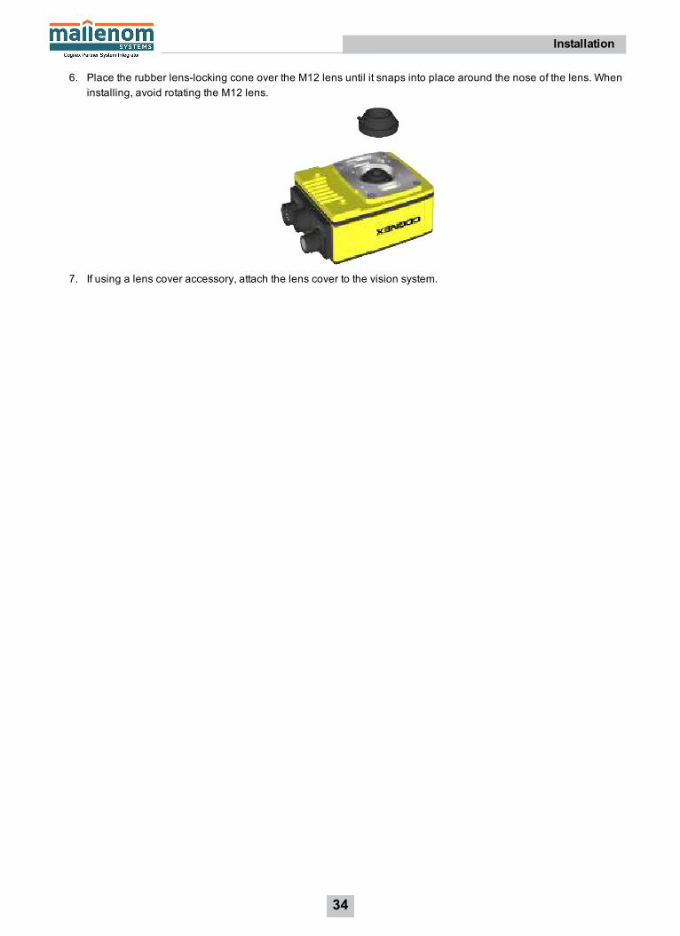
6. Place the rubber lens-locking cone over the M12 lens until it snaps into place around the nose of the lens. Wheninstalling, avoid rotating the M12 lens.
7. If using a lens cover accessory, attach the lens cover to the vision system.
34
Installation

Mount the Vision SystemThe vision system provides mounting holes for attachment to a mounting surface.
CAUTION: It is recommended the vision system be grounded, either by mounting the vision system to a fixture thatis electrically grounded or by attaching a wire from the vision system’s mounting fixture to frame ground or Earthground. If a ground wire is used, it should be attached to one of the four mounting points on the back plate of thevision system; not to the mounting points on the front of the vision system.
1. Align the holes on the mounting surface with the mounting holes on the vision system.
2. Insert the M3 screws into the mounting holes and tighten using a 2.5mm hex wrench; the maximum torque is 0.90Nm (8 in-lb).
Note: The maximum insertion depth of the M3 screws is 3.5mm in the rear housing and 3.75mm in the fronthousing, plus the thickness of the mounting material used.
35
Installation

Install the Mounting Bracket (ISB-7000-7K)The accessory mounting bracket kit (ISB-7000-7K) includes the mounting bracket, M3 screws (quantity 4) and a hexwrench for attaching the vision system to the mounting bracket. The mounting bracket also has 1/4 - 20, M6 and flatheadmounting holes for mounting the vision system to a mounting surface. Refer to Mounting Bracket Dimensions (ISB-7000-7K) on page 75 for more information.
CAUTION:l It is recommended the vision system be grounded, either by mounting the vision system to a fixture that iselectrically grounded or by attaching a wire from the vision system’s mounting fixture to frame ground orEarth ground. If a ground wire is used, it should be attached to one of the four mounting points on the backplate of the vision system; not to the mounting points on the front of the vision system.
l When mounting the vision system to the mounting bracket, use the M3 screws supplied with the mountingkit. If using the 1/4 - 20 or M6 screw holes on the mounting bracket to secure the vision system to a mountingsurface, the insertion depth of the screw should not exceed 7mm. Allowing the mounting screws to bottom inthe mounting hole can damage the vision system.
1. Align the mounting bracket with the mounting holes on the vision system.
2. Insert the M3 screws into the mounting holes and tighten using a 2.5mm hex wrench; the maximum torque is 0.90Nm (8 in-lb).
36
Installation
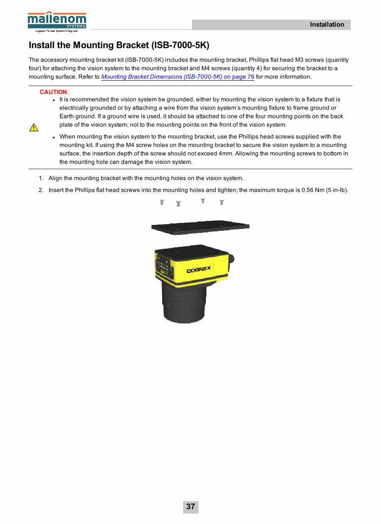
Install the Mounting Bracket (ISB-7000-5K)The accessory mounting bracket kit (ISB-7000-5K) includes the mounting bracket, Phillips flat head M3 screws (quantityfour) for attaching the vision system to the mounting bracket and M4 screws (quantity 4) for securing the bracket to amounting surface. Refer to Mounting Bracket Dimensions (ISB-7000-5K) on page 76 for more information.
CAUTION:l It is recommended the vision system be grounded, either by mounting the vision system to a fixture that iselectrically grounded or by attaching a wire from the vision system’s mounting fixture to frame ground orEarth ground. If a ground wire is used, it should be attached to one of the four mounting points on the backplate of the vision system; not to the mounting points on the front of the vision system.
l When mounting the vision system to the mounting bracket, use the Phillips head screws supplied with themounting kit. If using the M4 screw holes on the mounting bracket to secure the vision system to a mountingsurface, the insertion depth of the screw should not exceed 4mm. Allowing the mounting screws to bottom inthe mounting hole can damage the vision system.
1. Align the mounting bracket with the mounting holes on the vision system.
2. Insert the Phillips flat head screws into the mounting holes and tighten; the maximum torque is 0.56 Nm (5 in-lb).
37
Installation

Working Distance and Field of View (S-Mount/M12 Lenses)The working distance is the distance from the vision system lens to the part that needs to be inspected; field of view iswhat the vision system can see at that distance. As the working distance increases, so does the size of the field of view.
Note: The following charts show the design field of view of the In-Sight S-Mount/M12 accessory lenses and is fullymapped onto the image sensor. Additional field beyond the design field of view may have vignetting. For supportedIn-Sight lenses, refer to S-Mount/M12 Autofocus Accessories on page 13 and S-Mount/M12 Manual FocusAccessories on page 14.
38
Installation

39
Installation

Connect the External Light Cable (Optional)1. Remove the protective cap from the LIGHT connector, if present.
2. Connect the External Light cable’s M12 connector to the vision system's LIGHT connector.
3. Connect the other end of the Light cable to an external lighting device (for example, a strobe light).
Connect the Ethernet CableCAUTION: The Ethernet cable shield must be grounded at the far end. Whatever this cable is plugged into (usuallya switch or router) should have a grounded Ethernet connector. A digital voltmeter should be used to validate thegrounding. If the far end device is not grounded, a ground wire should be added in compliance with local electricalcodes.
1. Connect the Ethernet cable’s M12 connector to the vision system’s ENET connector.
2. Connect the Ethernet cable’s RJ-45 connector to a switch/router or PC, as applicable.
40
Installation
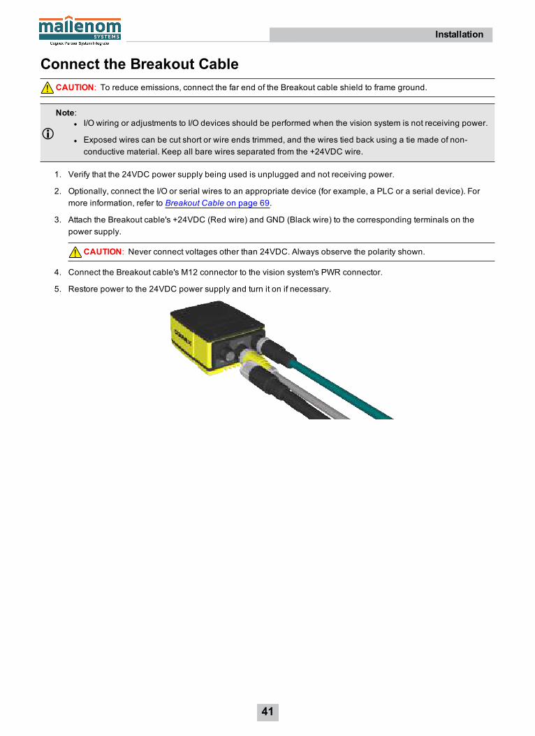
Connect the Breakout CableCAUTION: To reduce emissions, connect the far end of the Breakout cable shield to frame ground.
Note:l I/O wiring or adjustments to I/O devices should be performed when the vision system is not receiving power.
l Exposed wires can be cut short or wire ends trimmed, and the wires tied back using a tie made of non-conductive material. Keep all bare wires separated from the +24VDC wire.
1. Verify that the 24VDC power supply being used is unplugged and not receiving power.
2. Optionally, connect the I/O or serial wires to an appropriate device (for example, a PLC or a serial device). Formore information, refer to Breakout Cable on page 69.
3. Attach the Breakout cable's +24VDC (Red wire) and GND (Black wire) to the corresponding terminals on thepower supply.
CAUTION: Never connect voltages other than 24VDC. Always observe the polarity shown.
4. Connect the Breakout cable's M12 connector to the vision system's PWR connector.
5. Restore power to the 24VDC power supply and turn it on if necessary.
41
Installation
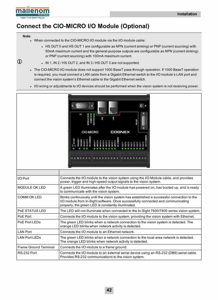
Connect the CIO-MICRO I/O Module (Optional)Note:
l When connected to the CIO-MICRO I/O module via the I/O module cable:
l HS OUT 0 and HS OUT 1 are configurable as NPN (current sinking) or PNP (current sourcing) with50mA maximum current and the general-purpose outputs are configurable as NPN (current sinking)or PNP (current sourcing) with 100mA maximum current.
l IN 1, IN 2 / HS OUT 2, and IN 3 / HS OUT 3 are not supported.
l The CIO-MICRO I/O module does not support 1000 BaseT pass-through operation. If 1000 BaseT operationis required, you must connect a LAN cable from a Gigabit Ethernet switch to the I/O module’s LAN port andconnect the vision system’s Ethernet cable to the Gigabit Ethernet switch.
l I/O wiring or adjustments to I/O devices should be performed when the vision system is not receiving power.
I/O Port Connects the I/O module to the vision system using the I/O Module cable, and providespower, trigger and high-speed output signals to the vision system.
MODULE OK LED A green LED illuminates after the I/O module has powered on, has booted up, and is readyto communicate with the vision system.
COMM OK LED Blinks continuously until the vision system has established a successful connection to theI/O module from In-Sight software. Once successfully connected and communicatingproperly, the green LED is constantly illuminated.
PoE STATUS LED The LED will not illuminate when connected to the In-Sight 7600/7800 series vision system.
PoE Port Connects the I/O module to the vision system, providing the vision system with Ethernet.
PoE Port LEDs The green LED blinks when a network connection to the vision system is detected. Theorange LED blinks when network activity is detected.
LAN Port Connects the I/O module to an Ethernet network.
LAN Port LEDs The green LED blinks when a network connection to the local area network is detected.The orange LED blinks when network activity is detected.
Frame Ground Terminal Connects the I/O module to a frame ground.
RS-232 Port Connects the I/O module to an external serial device using an RS-232 (DB9) serial cable.Provides RS-232 communications to the vision system.
42
Installation

High-Speed Output StatusLEDs (HS OUT 0 and HSOUT 1)
Illuminates to indicate the high-speed output signal for the In-Sight vision system hasswitched ON. The LEDs will illuminate even if the I/O module’s high-speed terminals arenot connected to anything. In addition, the I/O module displays the last known state of thehigh-speed output line; therefore the LEDs may be illuminated even if the vision system isdisconnected from the I/O module.
I/O and Trigger StatusLEDs
Illuminates to indicate that an input/output signal has switched ON.
Terminal Blocks Connects the I/O module to 24VDC power, trigger, external I/O, high-speed outputs andcommon connections.
Note: The I/O module's high-speed output terminals (labeled HS OUT 0 and HS OUT1) correspond to the vision system’s built-in high-speed outputs. These signals areconsidered high-speed because they pass directly through the I/O module withoutprocessing, which provides minimal delay.
1. Connect the I/O module's power wires.
CAUTION: Never connect the I/O module to a power source other than 24VDC. Any other voltage creates arisk of fire or shock and can damage the hardware. Do not connect the 24VDC power source to anyterminals other than the 24VDC + and – power terminals.
a. Verify that the 24VDC power supply being used is unplugged and not receiving power.
b. Use a screwdriver to loosen the I/O module's power terminals (labeled 24VDC + and –).
c. Insert the 24VDC + and – wires (16 - 22 AWG, solid or stranded wire) from the power supply into the24VDC + and – terminals on the I/O module.
d. Tighten the screw terminals with the screwdriver to secure the wire leads in the terminal block; themaximum torque is 0.1921 Nm (1.7 in-lb).
2. Connect a frame ground wire to the I/O module’s Frame Ground terminal. Connect the other end of the frameground wire to frame ground.
CAUTION: The shield ground connections of the RS-232 port, LAN port, PoE port, I/O port and FrameGround terminal are internally connected. The system grounding is designed to be at a zero groundpotential; this zero ground potential extends through the cable and to peripheral equipment (e.g. a visionsystem, PLC, etc.). To ensure safe operating conditions, it is strongly recommended that all groundconnections are checked to ensure that a zero ground potential is met.
43
Installation

3. Connect the I/O module's I/O wires.
a. Determine how I/O devices will be connected to the I/O module’s input and output terminals.
b. Use a screwdriver to loosen the appropriate screw terminals.
c. Connect the input and output wires to the input and output terminals.
d. Connect the other end of the input and output wires to the corresponding I/O device.
e. Tighten the screw terminals with the screwdriver to secure the wire leads in the terminal block; themaximum torque is 0.1921 Nm (1.7 in-lb).
4. To connect the vision system to a serial device, plug a RS-232 serial cable (DB9 male connector) into the I/Omodule’s RS-232 port and connect the other end of the cable to the serial device. Tighten the connector screwsto secure it to the I/O module.
5. Connect to an Ethernet network.
a. Connect a LAN cable (RJ-45 connector) to the I/O module’s LAN port.
b. Connect the other end of the LAN cable to a switch/router or PC, as applicable.
6. Connect the vision system's Ethernet cable.
a. Connect the Ethernet cable’s M12 connector to the vision system’s ENET connector.
b. Connect the Ethernet cable’s RJ-45 connector to the I/O module’s PoE port.
7. Connect the I/O Module cable (CCB-PWRIO-MOD-xx) to the vision system.
a. Connect the I/O Module cable’s M12 connector to the vision system’s PWR connector.
b. Connect the I/O Module cable’s DB15 connector to the I/O module’s I/O connector.
c. Restore power to the 24VDC power supply and turn it on if necessary.
44
Installation

Connect the CIO-1400 I/O Expansion Module (Optional)Note:
l When connected to the CIO-1400 I/O expansion module:
l HS OUT 0 and HS OUT 1 are configurable as NPN (current sinking) only with 50mA maximumcurrent and the general-purpose outputs are configurable as NPN (current sinking) or PNP(sourcing) with 100mA maximum current.
l IN 1, IN 2 / HS OUT 2, and IN 3 / HS OUT 3 are not supported.
l I/O wiring or adjustments to I/O devices should be performed when the vision system is not receiving power.
Connector/Indicator DescriptionCOMM OK LED (yellow) Illuminates to indicate that the vision system and I/O module are communicating
properly.
MODULE OK LED (yellow) Illuminates after the I/O module has initialized and is ready to communicate with thevision system.
I/O and Trigger Status LEDs(yellow)
Illuminates to indicate when an input/output has switched ON.
SENSOR Port Connects the I/O module to the vision system using the I/O Module cable, whichprovides power, trigger, I/O and RS-232 signals to the vision system.
RS232 OUT Port Connects the I/O module to an RS-232 serial cable, which provides RS-232communications between the I/O module and an external serial device.
Frame Ground Terminal Connects the I/O module to a common frame ground.
1. Connect the I/O module's power wires.
CAUTION: Never connect the I/O module to a power source other than 24VDC. Any other voltage creates arisk of fire or shock and can damage the hardware. Do not connect the 24VDC power source to anyterminals other than the 24VDC + and – power terminals.
a. Verify that the 24VDC power supply being used is unplugged and not receiving power.
b. Use a screwdriver to loosen the I/O module's power terminals (labeled 24VDC + and –).
c. Insert the 24VDC + and – wires (16 - 26 AWG, solid or stranded wire) from the power supply into the24VDC + and – terminals on the I/O module.
d. Tighten the screw terminals with the screwdriver to secure the wire leads in the terminal block; themaximum torque is 0.4 Nm (3.5 in-lb).
45
Installation
2. Connect a frame ground wire to the I/O module’s Frame Ground terminal. Connect the other end of the frameground wire to frame ground.
CAUTION: The shield ground connections of the RS-232 port, SENSOR port and Frame Ground terminalare internally connected. The system grounding is designed to be at a zero ground potential; this zeroground potential extends through the cable and to peripheral equipment (e.g. a vision system, PLC, etc.). Toensure safe operating conditions, it is strongly recommended that all ground connections are checked toensure that a zero ground potential is met.
3. Connect the I/O module's I/O wires.
a. Determine how I/O devices will be connected to the I/O module’s input and output terminals.
b. Use a screwdriver to loosen the appropriate screw terminals.
c. Connect the input and output wires to the input and output terminals.
d. Connect the other end of the input and output wires to the corresponding I/O device.
e. Tighten the screw terminals with the screwdriver to secure the wire leads in the terminal block; themaximum torque is 0.4 Nm (3.5 in-lb).
4. To connect the vision system to a serial device, plug an RS-232 serial cable (DB9 male connector) into the I/Omodule’s RS232 OUT port and connect the other end of the cable to the serial device. Tighten the connectorscrews to secure it to the I/O module.
5. Connect the I/O Module cable (CCB-PWRIO-MOD-xx) to the vision system.
a. Connect the I/O Module cable’s M12 connector to the vision system’s PWR connector.
b. Connect the I/O Module cable’s DB15 connector to the I/O module’s SENSOR connector.
c. Restore power to the 24VDC power supply and turn it on if necessary.
46
Installation
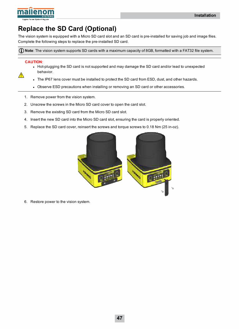
Replace the SD Card (Optional)The vision system is equipped with a Micro SD card slot and an SD card is pre-installed for saving job and image files.Complete the following steps to replace the pre-installed SD card.
Note: The vision system supports SD cards with a maximum capacity of 8GB, formatted with a FAT32 file system.
CAUTION:l Hot-plugging the SD card is not supported and may damage the SD card and/or lead to unexpectedbehavior.
l The IP67 lens cover must be installed to protect the SD card from ESD, dust, and other hazards.
l Observe ESD precautions when installing or removing an SD card or other accessories.
1. Remove power from the vision system.
2. Unscrew the screws in the Micro SD card cover to open the card slot.
3. Remove the existing SD card from the Micro SD card slot.
4. Insert the new SD card into the Micro SD card slot, ensuring the card is properly oriented.
5. Replace the SD card cover, reinsert the screws and torque screws to 0.18 Nm (25 in-oz).
6. Restore power to the vision system.
47
Installation

Replace the LED Ring Light (Optional)The illumination accessory (ISLM-7000-WHI) has a white LED ring light pre-installed. Complete the following steps toreplace the pre-installed LED ring light.
CAUTION:l Do not hot-plug the illumination accessory; verify the vision system is not receiving power when connectingor disconnecting the illumination accessory. Failure to remove power during this procedure may result indamage to the vision system and/or the lighting accessory.
l Tighten all of the illumination accessory screws in the following sequence.
1. Remove power from the vision system.
2. Use a 2mm hex wrench to remove the four M3 x 12mm screws from the front cover. Remove the front cover.
48
Installation

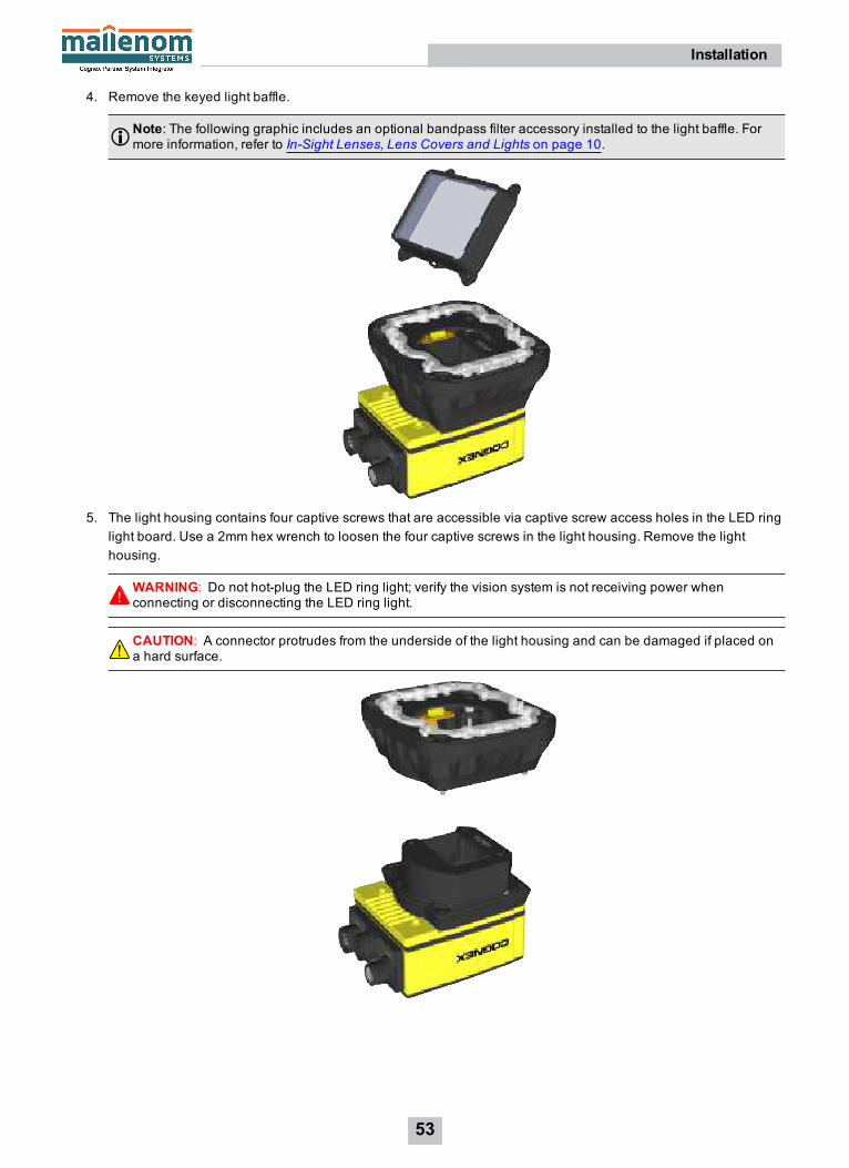
3. Remove the keyed light baffle.
Note: The following graphic includes an optional bandpass filter accessory installed to the light baffle. Formore information, refer to In-Sight Lenses, Lens Covers and Lights on page 10.
4. Use a 2mm hex wrench to remove the four M2.5 x 6mm screws from the LED ring light. The screw holes areindicated by a triangle symbol ►. Remove the LED ring light from the light housing.
49
Installation

5. Place the new LED ring light inside the light housing, with "TOP" oriented upward. Insert the four M2.5 x 6mmscrews into the screw holes indicated by a triangle symbol ►. Tighten the screws using a 2mm hex wrench; themaximum torque is 0.34 Nm (3 in-lb).
WARNING: Do not hot-plug the LED ring light; verify the vision system is not receiving power whenconnecting or disconnecting the LED ring light.
50
Installation

6. The light baffle is keyed to fit the LED ring light structure and snaps into place with the keyed tabs sitting flushover each light housing captive screw access hole. With the “TOP” of the light housing oriented upward, tilt thelight baffle toward the light housing and maneuver the light baffle past the top of the LED ring light structure.Compress the light baffle and maneuver the bottom of the light baffle past the bottom of the LED ring lightstructure until the light baffle snaps into place.
Note: The following graphic includes an optional bandpass filter accessory installed to the light baffle. Formore information, refer to In-Sight Lenses, Lens Covers and Lights on page 10.
7. Place the light cover on the light housing. Align the central clear region of the light cover with the light baffleedges. Insert the four M3 x 12mm screws and use a 2mm hex wrench to torque screws to 0.31 Nm (2.75 in-lb).
8. Restore power to the vision system.
51
Installation

Replace the M12 Autofocus Lens (Optional)The autofocus accessory (ISAF-7000-8mm) has an 8mm M12 lens pre-installed. Complete the following steps to replacethe pre-installed M12 lens.
CAUTION:l Do not hot-plug the illumination accessory; verify the vision system is not receiving power when connectingor disconnecting the illumination accessory. Failure to remove power during this procedure may result indamage to the vision system and/or the lighting accessory.
l Tighten all of the illumination accessory screws in the following sequence.
1. If the autofocus module is already installed to the vision system, you must first log onto the vision system using In-Sight Explorer software and reset the focus position to 0. Refer to the In-Sight ® Explorer Help file for moreinformation.
2. Remove power from the vision system.
3. Use a 2mm hex wrench to remove the four M3 x 12mm screws from the front cover. Remove the front cover.
52
Installation
4. Remove the keyed light baffle.
Note: The following graphic includes an optional bandpass filter accessory installed to the light baffle. Formore information, refer to In-Sight Lenses, Lens Covers and Lights on page 10.
5. The light housing contains four captive screws that are accessible via captive screw access holes in the LED ringlight board. Use a 2mm hex wrench to loosen the four captive screws in the light housing. Remove the lighthousing.
WARNING: Do not hot-plug the LED ring light; verify the vision system is not receiving power whenconnecting or disconnecting the LED ring light.
CAUTION: A connector protrudes from the underside of the light housing and can be damaged if placed ona hard surface.
53
Installation
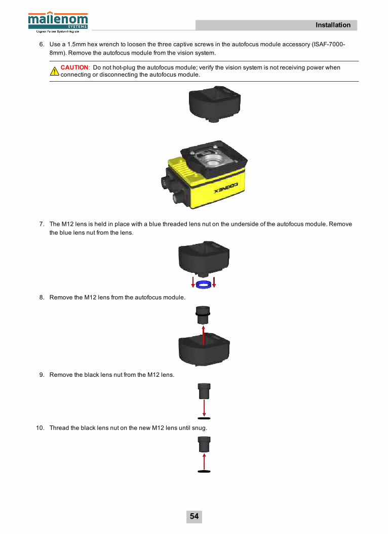
6. Use a 1.5mm hex wrench to loosen the three captive screws in the autofocus module accessory (ISAF-7000-8mm). Remove the autofocus module from the vision system.
CAUTION: Do not hot-plug the autofocus module; verify the vision system is not receiving power whenconnecting or disconnecting the autofocus module.
7. The M12 lens is held in place with a blue threaded lens nut on the underside of the autofocus module. Removethe blue lens nut from the lens.
8. Remove the M12 lens from the autofocus module.
9. Remove the black lens nut from the M12 lens.
10. Thread the black lens nut on the new M12 lens until snug.
54
Installation

11. Drop the new M12 lens into the module.
12. Once the lens is in the module, quarter turn the thread of the lens clockwise, to ensure the lens is seated in thelens carrier.
13. With the chamfer side of the blue lens nut facing the module, thread the blue lens nut on the lens and finger-tighten until snug. The lens nut should be tight enough that it does not fall off due to vibration.
Chamfer Side of Blue Lens Nut:
14. There are two alignment pins on the base of the autofocus module; seat the pins into the vision system faceplate.There are three captive screws in the autofocus module; partially thread the screws into the vision systemfaceplate using a 1.5mm hex wrench. Once threaded, torque screws to 0.5 Nm (4.43 in-lb) using a torquescrewdriver with a 1.5mm hex torque bit capable of reaching 15mm into a 2.5mm diameter hole (for example,Wiha Tools 1.5mm Hex Metric Torque Blade [SKU 28545] used with the Adjustable Torque Handle [SKU 28550]).
55
Installation
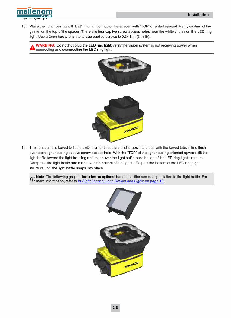
15. Place the light housing with LED ring light on top of the spacer, with “TOP” oriented upward. Verify seating of thegasket on the top of the spacer. There are four captive screw access holes near the white circles on the LED ringlight. Use a 2mm hex wrench to torque captive screws to 0.34 Nm (3 in-lb).
WARNING: Do not hot-plug the LED ring light; verify the vision system is not receiving power whenconnecting or disconnecting the LED ring light.
16. The light baffle is keyed to fit the LED ring light structure and snaps into place with the keyed tabs sitting flushover each light housing captive screw access hole. With the “TOP” of the light housing oriented upward, tilt thelight baffle toward the light housing and maneuver the light baffle past the top of the LED ring light structure.Compress the light baffle and maneuver the bottom of the light baffle past the bottom of the LED ring lightstructure until the light baffle snaps into place.
Note: The following graphic includes an optional bandpass filter accessory installed to the light baffle. Formore information, refer to In-Sight Lenses, Lens Covers and Lights on page 10.
56
Installation

17. Place the light cover on the light housing. Align the central clear region of the light cover with the light baffleedges. Insert the four M3 x 12mm screws and use a 2mm hex wrench to torque screws to 0.31 Nm (2.75 in-lb).
18. Restore power to the vision system.
57
Installation

Remove the Illumination Accessory PCBIf the illumination accessory (ISLM-7000-WHI) must be uninstalled from the vision system, complete the following stepsto safely remove the PCB and avoid damage to the vision system.
CAUTION: Do not hot-plug the illumination accessory; verify the vision system is not receiving power whenconnecting or disconnecting the illumination accessory. Failure to remove power during this procedure may resultin damage to the vision system and/or the lighting accessory.
1. Remove power from the vision system.
2. Use a 2mm hex wrench to remove the four M3 x 6mm spacer screws. Remove the spacer.
3. The vision system faceplate includes two lift points on either side of the PCB. Position an insulated extractor tool(for example, Jonard Tools S-340 DIP/IC Extractor) under the edges of the PCB.
58
Installation

4. Once the extractor is engaged under the edges of the PCB, gently pull upward to disengage the PCB from theinternal connector and remove the PCB.
5. Verify the removal process did not damage mating components.
59
Installation

SpecificationsThe following sections list general specifications for the vision system.
Vision System SpecificationsSpecifications 7600 7800 7801 7802
Minimum FirmwareRequirement
In-Sight version 5.4.0
Job/Program Memory 7.2GB non-volatile flash memory; unlimited storage via remote network device.
Image ProcessingMemory
512MB SDRAM
Sensor Type 1/1.8 inch CMOS, global shutter
Sensor Properties 4.5mm diagonal, 4.5 x 4.5µm sq. pixels 7.38mm diagonal, 4.5x 4.5µm sq. pixels
9mm diagonal, 4.5 x4.5µm sq. pixels
Maximum ImageResolution (pixels)1
800 x 6002 1280 x 1024 1600 x 1200
640 x 480
Electronic ShutterSpeed
14µs to 550ms 17µs to 750ms 20µs to 940ms
14µs to 520ms
Acquisition Rapid reset, progressive scan, full-frame integration.
Bit Depth 256 grey levels (8 bits/pixel)
Frames Per Second3 165 full frames per second. 76 full frames persecond.
53 full frames persecond.217 full frames per second.
Lens Type C-Mount or M12
SD Card Slot 1 SD card slot for saving job and image files. The vision system supports SD cards with amaximum capacity of 8GB, formatted with a FAT32 file system.
Trigger 1 opto-isolated, acquisition trigger input. Remote software commands via Ethernet.
Discrete Inputs l 3 general-purpose inputs when connected to the Breakout cable.4
l 8 general-purpose inputs available when connected to the CIO-MICRO I/O module viathe I/O module cable.
l 7 general-purpose inputs available when connected to the CIO-1400 I/O module viathe I/O module cable.
1The number of image sensor rowsare configurable and can be set within the In-Sight Explorer software. Decreasing the number of rowswillincrease the number of framesper second acquired by the vision system. Refer to the AcquireImage topic in the In-Sight®Explorer Help file formore information.
2The default resolution for the In-Sight 7600 and 7800 vision system is 800 x600 pixels. The vision system's resolution can be configured as640x480 pixelswithin the In-Sight Explorer software. Refer to the In-Sight®Explorer Help file for more information.
3Maximum framesper second is job-dependent, based on theminimum exposure for a full image frame capture using the dedicated acquisitiontrigger, and assumes there is no user interface connection to the vision system.
4When connected to the Breakout cable, the vision system allows for bi-directional high-speed outputs and general-purpose inputs for HSOUT2 / IN 2 and HSOUT 3 / IN 3. These linesare configured asoutputs bydefault.
60
Specifications

Specifications 7600 7800 7801 7802Discrete Outputs l 4 high-speed outputs when connected to the Breakout cable.1
l 2 high-speed outputs, plus 8 general-purpose outputs available when connected tothe CIO-MICRO I/O module via the I/O module cable.
l 2 high-speed outputs, plus 6 general-purpose outputs available when connected tothe CIO-1400 I/O module via the I/O module cable.
Status LEDs SD Card Status, Pass/Fail LED and Indicator Ring, Network LED and Error LED.
LED Ring Light White, Red, Blue or IR LED ring light used with the illumination accessory (ISLM-7000-WHI).
l White LED color temperature: 4000 K
l Red LED wavelength: 617 nm
l Blue LED wavelength: 455 nm
l IR LED wavelength: 850 nm
Note: Refer to DataMan documentation for DataMan accessory specifications.
NetworkCommunication
1 Ethernet port, 10/100/1000 BaseT with auto MDIX. IEEE 802.3 TCP/IP Protocol. SupportsDHCP, static and link-local IP address configuration.
1588 Support Timestamp Resolution: 8nsSynchronization Accuracy Through Transparent Clock: 5μs
Serial Communication RS-232C when connected to the Breakout cable2 or a compatible I/O module.
Power Consumption 24VDC ±10%, 1.5A maximum
Power Output 24VDC @ 750mA maximum to external light.
Material Die-cast and extruded aluminum housing.
Finish Painted.
Mounting Four M3 threaded mounting holes. 1/4-20, M6 and flathead mounting holes also available onmounting bracket accessory (ISB-7000-7K). M4 mounting holes also available on mountingbracket accessory (ISB-7000-5K).
Dimensions l 35.7mm (1.41in) x 60.5mm (2.38in) x 90.1mm (3.55in)
l 81.7mm (3.21in) x 60.5mm (2.38in) x 90.1mm (3.55in) with standard lens coveraccessory (COV-7000-CMNT).
l 102.7mm (4.04in) x 60.5mm (2.38in) x 90.1mm (3.55in) with extended lens coveraccessory (COV-7000-CMNT-EX).
l 77.4mm (3.05in) x 88.9mm (3.50in) x 97.2mm (3.83in) with illumination accessory(ISLM-7000-WHI).
Weight 240 g (8.47 oz.)
Case Temperature3 0°C to 50°C (32°F to 122°F).
Storage Temperature -20°C to 80°C (-4°F to 176°F)
Humidity < 80% non-condensing
1When connected to the Breakout cable, the vision system allows for bi-directional high-speed outputs and general-purpose inputs for HSOUT2 / IN 2 and HSOUT 3 / IN 3. These linesare configured asoutputs bydefault.
2 If hardware handshaking is required, an I/Omodulemust be used.3Case temperature can be verified using the EVGetSystemConfig(“Internal.Temperature”) Extended NativeMode command.When issued, itreturns the vision system's internal temperature in degreesCelsius, which will be about 3 to 5 degreesabove the vision system casetemperature. Refer to the In-Sight®Explorer Help file for more information. A thermal scanner can also be used to determine the vision systemcase temperature. Additional coolingmeasuresare required if the case temperature cannot be kept below 50°C. Examplesof suchmeasuresinclude: extra heat sinking and/or air movement.
61
Specifications

Specifications 7600 7800 7801 7802Protection IP67 with cables and appropriate lens cover attached.
Shock (Shipping andStorage)
IEC 60068-2-27: 18 shocks (3 shocks in each polarity in each (X, Y, Z) axis) 80 Gs (800m/s2 at11ms, half-sinusoidal) with cables or cable plugs and appropriate lens cover attached.
Vibration (Shipping andStorage)
IEC 60068-2-6: vibration test in each of the three main axis for 2 hours @ 10 Gs (10 to 500 Hzat 100m/s2 / 15mm) with cables or cable plugs and appropriate lens cover attached.
Regulations/Conformity CE, FCC, KCC, TÜV SÜD NRTL, EU RoHS, China RoHS
62
Specifications
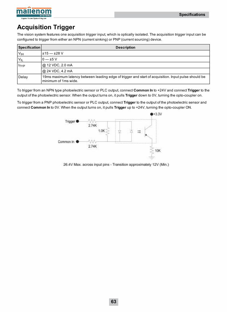
Acquisition TriggerThe vision system features one acquisition trigger input, which is optically isolated. The acquisition trigger input can beconfigured to trigger from either an NPN (current sinking) or PNP (current sourcing) device.
Specification DescriptionVIH ±15 — ±28 V
VIL 0 — ±5 V
ITYP @12 VDC, 2.0 mA
@ 24 VDC, 4.2 mA
Delay 19ms maximum latency between leading edge of trigger and start of acquisition. Input pulse should beminimum of 1ms wide.
To trigger from an NPN type photoelectric sensor or PLC output, connect Common In to +24V and connect Trigger to theoutput of the photoelectric sensor. When the output turns on, it pulls Trigger down to 0V, turning the opto-coupler on.
To trigger from a PNP photoelectric sensor or PLC output, connect Trigger to the output of the photoelectric sensor andconnect Common In to 0V. When the output turns on, it pulls Trigger up to +24V, turning the opto-coupler ON.
63
Specifications

General-Purpose InputsThe vision system features three1 built-in general-purpose inputs, which are optically isolated. The inputs can beconfigured as either NPN (current sinking) or PNP (current sourcing) lines.
Specification DescriptionVIH ±15 — ±28 V
VIL 0 — ±5 V
ITYP @12 VDC, 2.0 mA
@ 24 VDC, 4.2 mA
Delay 1.11ms maximum latency between leading edge of trigger and start of acquisition. Input pulse should beminimum of 1ms wide.
For NPN lines, to utilize an input, connect Common In to +24V and connect In 1 to the output of the photoelectric sensoror PLC. When the output turns on, it pulls In 1 down to 0V, turning the opto-coupler on.
For PNP lines, to utilize an input, connect In 1 to the output of the detector and connect Common In to 0V. When theoutput turns on, it pulls In 1 up to +24V, turning the opto-coupler ON.
1When connected to the Breakout cable, the vision system allows for bi-directional high-speed outputs and general-purpose inputs for HSOUT2 / IN 2 and HSOUT 3 / IN 3. These linesare configured asoutputs bydefault.
64
Specifications

High-Speed OutputsThe vision system features four1 built-in, high-speed outputs, which are optically isolated. The high-speed outputs can beused as either NPN (current sinking) or PNP (current sourcing) lines.
Specification DescriptionVoltage 26.4V maximum through external load
Current 50mA maximum sink current
OFF state leakage current 100µA
External load resistance 240 Ohms to 10K Ohms
Each line rated at a maximum 50mA, protected against over-current, short circuits and transients fromswitching inductive loads. High current inductive loads require external protection diode.
Delay2 10μs (maximum due to opto-isolators turning ON).
For NPN lines, the external load should be connected between the output and the positive supply voltage (<26.4V). Theoutputs pull down to less than 3V when ON, which causes current to flow through the load. When the outputs are OFF, nocurrent flows through the load.
For PNP lines, the external load should be connected between the output and the negative supply voltage (0V). Whenconnected to a 24VDC power supply, the outputs pull up greater than 21V when ON, and current flows through the load.When the outputs are OFF, no current flows through the load.
1When connected to the Breakout cable, the vision system allows for bi-directional high-speed outputs and general-purpose inputs for HSOUT2 / IN 2 and HSOUT 3 / IN 3. These linesare configured asoutputs bydefault.2Delaywhen opto-isolators turn OFF dependson the load to which the output is connected.With a 240Ohm load, themaximum delaywill be200μs.
65
Specifications

High-Speed Output WiringTo connect to an NPN-compatible PLC input, connect High-Speed Output 0, Output 1, Output 2, or Output 3 directly to thePLC input. When enabled, the output pulls the PLC input down to less than 3V.
To connect to a PNP-compatible PLC input, connect High-Speed Output 0, Output 1, Output 2 or Output 3 directly to thePLC input. When enabled, the output pulls the PLC input up to greater than 21V.
To connect the high-speed outputs to a relay, LED or similar load, connect the negative side of the load to the output andthe positive side to +24V. When the output switches on, the negative side of the load is pulled down to less than 3V, and24V appears across the load. Use a protection diode for a large inductive load, with the anode connected to the outputand the cathode connected to +24V.
66
Specifications
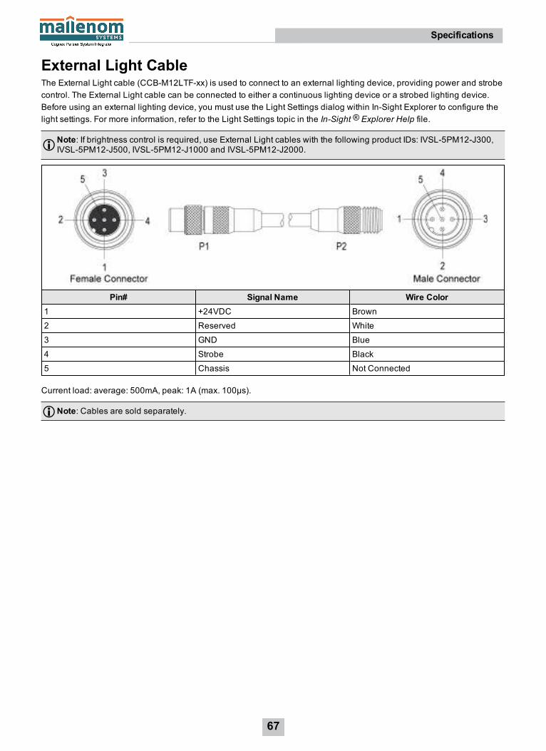
External Light CableThe External Light cable (CCB-M12LTF-xx) is used to connect to an external lighting device, providing power and strobecontrol. The External Light cable can be connected to either a continuous lighting device or a strobed lighting device.Before using an external lighting device, you must use the Light Settings dialog within In-Sight Explorer to configure thelight settings. For more information, refer to the Light Settings topic in the In-Sight ® Explorer Help file.
Note: If brightness control is required, use External Light cables with the following product IDs: IVSL-5PM12-J300,IVSL-5PM12-J500, IVSL-5PM12-J1000 and IVSL-5PM12-J2000.
Pin# Signal Name Wire Color1 +24VDC Brown
2 Reserved White
3 GND Blue
4 Strobe Black
5 Chassis Not Connected
Current load: average: 500mA, peak: 1A (max. 100µs).
Note: Cables are sold separately.
67
Specifications

Ethernet CableThe RJ-45 to M12 X-coded Ethernet cable provides Ethernet connectivity and supplies power to the vision system.
P1 Pin Number Wire Color Signal Name P2 Pin Number1 White/Orange TxRx A + 1
2 Orange TxRx A - 2
3 White/Green TxRx B + 3
4 Blue TxRx C + 8
5 White/Blue TxRx C - 7
6 Green TxRx B - 4
7 White/Brown TxRx D + 5
8 Brown TxRx D - 6
Note:l Cables are sold separately.
l The wiring for this cable follows standard industrial Ethernet M12 specifications. This differs from the 568Bstandard.
CAUTION: The Ethernet cable shield must be grounded at the far end. Whatever this cable is plugged into (usuallya switch or router) should have a grounded Ethernet connector. A digital voltmeter should be used to validate thegrounding. If the far end device is not grounded, a ground wire should be added in compliance with local electricalcodes.
68
Specifications

Breakout CableThe Breakout cable provides connections to an external power supply, the acquisition trigger input, general-purposeinputs, high-speed outputs, and RS-232 serial communications. The Breakout cable is not terminated.
Pin# Signal Name Wire Color
1 IN 2 / HS OUT 2 Yellow
2 RS-232 TRANSMIT1 White/Yellow
3 RS-232 RECEIVE2 Brown
4 IN 3 / HS OUT 3 White/Brown
5 IN 1 Violet
6 COMMON IN White/Violet
7 +24VDC Red
8 GND Black
9 COMMON OUT Green
10 TRIGGER Orange
11 HS OUT 0 Blue
12 HS OUT 1 Grey
Note:l Cables are sold separately.
l Exposed wires can be cut short or wire ends trimmed, and the wires tied back using a tie made of non-conductive material. Keep all bare wires separated from the +24VDC wire.
l I/O wiring or adjustments to I/O devices should be performed when the vision system is not receiving power.
1 If hardware handshaking is required, an I/Omodulemust be used.2 If hardware handshaking is required, an I/Omodulemust be used.
69
Specifications

I/O Module CableThe I/O Module cable connects the vision system directly to a compatible I/O module via the DB15 connector. When theI/O module is used, all power and communication lines used by the vision system are connected using the I/O Modulecable.
P1 Pin# Signal Name Wire Color Signal Name P2 Pin#1 IN 2 / HS OUT 2 Yellow Not Used Not Used
2 RS-232 TRANSMIT White/Yellow RS-232 TRANSMIT 73 RS-232 RECEIVE Brown RS-232 RECEIVE 64 IN 3 / HS OUT 3 White/Brown Not Used Not Used5 IN 1 Violet Not Used Not Used6 COMMON IN White/Violet TRIGGER- 37 +24VDC Red +24VDC 18 GND Black -24VDC 89 COMMON OUT Green -24VDC 810 TRIGGER Orange TRIGGER+ 211 HS OUT 0 Blue HS OUT 0 412 HS OUT 1 Grey HS OUT 1 5
Note: Cables are sold separately.
70
Specifications
Vision System DimensionsNote:
l All dimensions are in millimeters [inches] and are for reference purposes only.
l All specifications are for reference purpose only and may be changed without notice.
71
Specifications

Vision System Dimensions (with Standard Lens Cover)
Note:l All dimensions are in millimeters [inches] and are for reference purposes only.
l All specifications are for reference purpose only and may be changed without notice.
72
Specifications
Vision System Dimensions (with Extended Lens Cover)
Note:l All dimensions are in millimeters [inches] and are for reference purposes only.
l All specifications are for reference purpose only and may be changed without notice.
73
Specifications

Vision System Dimensions (with Illumination and Lens Cover)
Note:l All dimensions are in millimeters [inches] and are for reference purposes only.
l All specifications are for reference purpose only and may be changed without notice.
74
Specifications

Mounting Bracket Dimensions (ISB-7000-7K)
Note:l All dimensions are in millimeters [inches] and are for reference purposes only.
l All specifications are for reference purpose only and may be changed without notice.
75
Specifications

Mounting Bracket Dimensions (ISB-7000-5K)
Note:l All dimensions are in millimeters [inches] and are for reference purposes only.
l All specifications are for reference purpose only and may be changed without notice.
76
Specifications

Vision System C-Mount Lens Clearance Dimensions
Note:l All dimensions are in millimeters [inches] and are for reference purposes only.
l All specifications are for reference purpose only and may be changed without notice.
77
Specifications

Cleaning/MaintenanceClean the Vision System HousingTo clean the outside of the vision system housing, use a small amount of mild detergent cleaner or isopropyl alcohol ona cleaning cloth. Do not pour the cleaner directly onto the vision system housing.
CAUTION: Do not attempt to clean any In-Sight product with harsh or corrosive solvents, including lye, methyl ethylketone (MEK) or gasoline.
Clean the Vision System Image Sensor WindowTo remove dust from the outside of the image sensor window, use a pressurized air duster. The air must be free of oil,moisture or other contaminants that could remain on the glass and possibly degrade the image. Do not touch the glasswindow. If oil/smudges still remain, clean the window with a cotton bud using alcohol (ethyl, methyl or isopropyl). Do notpour the alcohol directly on the window.
78
Cleaning/Maintenance
