in-situ oil-shale recovery, carbon capture and storage...
TRANSCRIPT

SJF 10-2005
In-situ oil-shale recovery, carbon capture and storage, and the importance of large
projects
S. Julio FriedmannEnergy & Environment Directorate, LLNL
Visiting Scientist, Earth Atmospheric & Planetary Science, MIT

SJF 10-2005
Conclusions
Oil shale development and recovery strategies occur in the framework of a carbon-constrained world, where carbon capture and sequestration (CCS) is an enabling technology
The current state of knowledge strongly supports successful deployment of CCS
LARGE SCALE tests are crucial to understanding successful deployment of carbon capture and sequestration (CCS) and creating appropriate policy/economic structures.
No test planned to date is sufficient with respect to scale, duration, monitoring, and analysis.

SJF 10-2005
A central priority of a US oil shale strategy A central priority of a US oil shale strategy should include large CCS projectsshould include large CCS projects
One large scale field experiment in the Piceance Creek basin could largely resolve
scientific uncertainties and demonstrate operational practice for practical
sequestration projects

SJF 10-2005
High Concern over Energy
Supply
High Carbon Constraint
Low Carbon Constraint
Low Concern over Energy
Supply
Constrained World
Low Carbon World
Security Conscious
World
Unconstrained World
Future energy scenarios focus on two major axes of concern
SJF 10-2005
The Times They Are a-Changing…
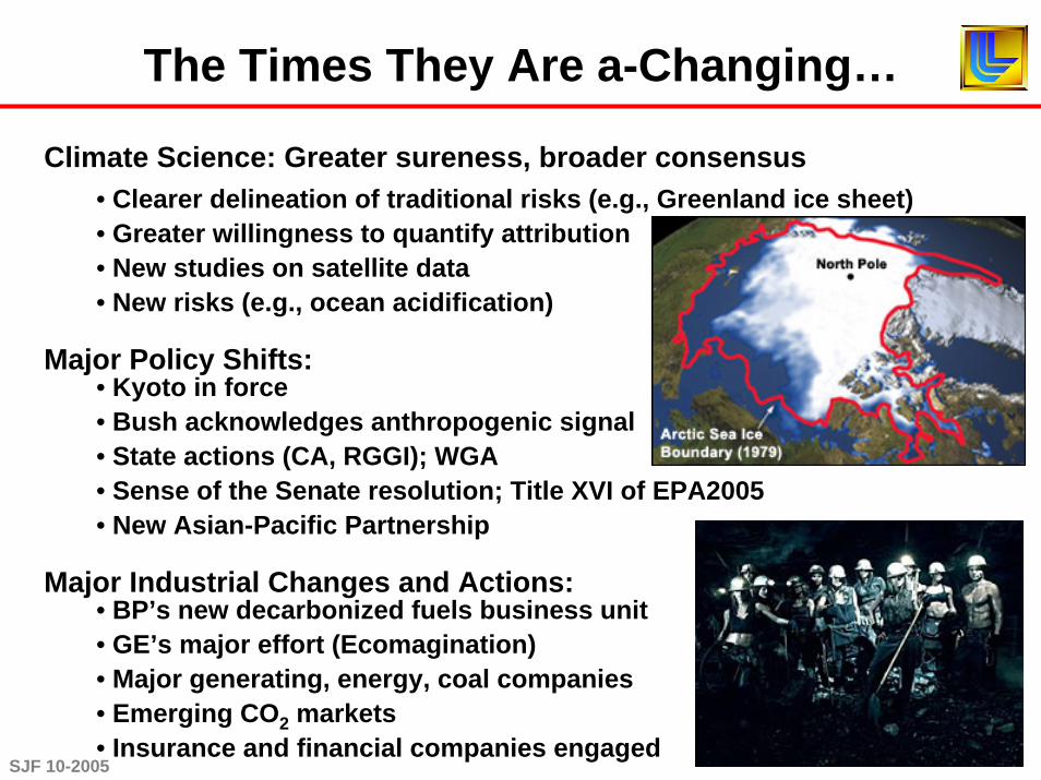
Climate Science: Greater sureness, broader consensus• Clearer delineation of traditional risks (e.g., Greenland ice sheet)• Greater willingness to quantify attribution• New studies on satellite data• New risks (e.g., ocean acidification)
Major Policy Shifts:• Kyoto in force• Bush acknowledges anthropogenic signal• State actions (CA, RGGI); WGA• Sense of the Senate resolution; Title XVI of EPA2005• New Asian-Pacific Partnership
Major Industrial Changes and Actions:• BP’s new decarbonized fuels business unit• GE’s major effort (Ecomagination)• Major generating, energy, coal companies• Emerging CO2 markets• Insurance and financial companies engaged
SJF 10-2005
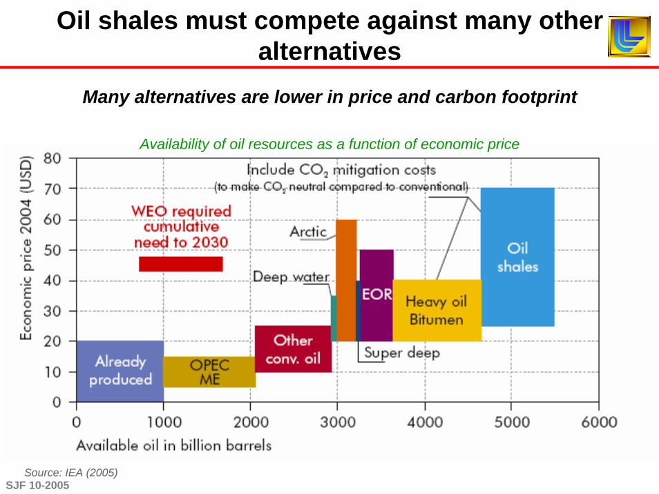
Oil shales must compete against many other alternatives
Availability of oil resources as a function of economic price
Source: IEA (2005)
Many alternatives are lower in price and carbon footprint

SJF 10-2005
Concern relating to Threat of Climate Change
Con
cern
ove
r Fut
ure
Ava
ilabi
lity
of O
il an
d G
as
High
HighLow
Low
Evaluating liquid transport fuels in the four scenarios reveals need to decarbonize oil shales
AdvBiofuels
Carbon Free H2 for
Transport
CTL
GTL
Heavy Oil
CO2 EnhancedRecovery
Ultra Deep Water
Arctic
transport sector
Capture & Storage
Capture & Storage
CNG
Hybrids
C&S
Vehicle Efficiency (e.g. light weighting)
- supply side options
- demand side options
Key:Dieselisation
Conv.Biofuels
OilShale
Capture & Storage

SJF 10-2005
Carbon dioxide can be stored in several geological targets, usually as a supercritical phase
Benson, Cook et al., in pressBenson, Cook et al., in pressIPCC Report on Carbon SequestrationIPCC Report on Carbon Sequestration
Saline AquifersDepleted Oil & Gas fields
(w/ or w/o EOR and EGR)Unmineable Coal Seams
(w/ or w/o ECBM)Other options
(e.g., oil shales, basalts)
The storage mechanisms vary by reservoir type
EOR/Depleted Oil & Gas fields are early actorsSaline aquifers hold the largest storage capacity
There is both overlap and distinctiveness between them

SJF 10-2005
High purity (>95%) CO2 streams are required for storage
Refineries, fertilizer & ethanol plants, polygeneration, cement plants, and gas processing facilities are cheapest.
Typical PC plant $40-60/t CO2
Typical gasified plant $30-40/t CO2
Oxyfired combustion $30-40/t CO2*
Low-cost opportunities $ 5-10/t CO2
* Not yet ready for prime time
Mostly natural sources (e.g., CO2 domes)
Capture devices on standard existing plants (e.g., PC) are relatively high in cost.
At present, all three approaches to carbon capture and separation appear equally viable
Amine stripping, Sleipner
Wabash IGCC plant, Indiana
Clean Energy Systems, CA

SJF 10-2005
Storage mechanisms are sufficiently well understood to be confident of effectiveness
Physical trapping•• Impermeable cap rockImpermeable cap rock•• Either geometric or Either geometric or hydrodynamic stabilityhydrodynamic stability
Residual phase trappingResidual phase trapping•• Capillary forces Capillary forces immobilized fluidsimmobilized fluids
•• Sensitive to pore Sensitive to pore geometry geometry (<25% pore vol.)(<25% pore vol.)
Solution/Mineral TrappingSolution/Mineral Trapping•• Slow kineticsSlow kinetics•• High permanenceHigh permanence
Gas adsorptionGas adsorption•• For organic minerals For organic minerals only (coals, oil shales)only (coals, oil shales)
1.0 MgCO3
0.2NaAlCO3(OH)2

SJF 10-2005
Site selection due diligence requires characterization & validation of ICE
Injectivity Capacity EffectivenessInjectivity
• Rate of volume injection• Must be sustainable (months – years)
Capacity• Bulk (integrated) property• Total volume estimate• Sensitive to process
Effectiveness• Ability for a site to store CO2• Long beyond the lifetime of the project• Most difficult to define or defend
Gasda et. al, 2005
SJF 10-2005
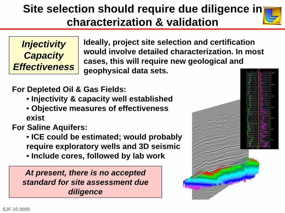
Site selection should require due diligence in characterization & validation
InjectivityCapacity
Effectiveness
For Depleted Oil & Gas Fields:• Injectivity & capacity well established• Objective measures of effectiveness exist
For Saline Aquifers:• ICE could be estimated; would probably require exploratory wells and 3D seismic• Include cores, followed by lab work
Ideally, project site selection and certification would involve detailed characterization. In most cases, this will require new geological and geophysical data sets.
At present, there is no accepted standard for site assessment due
diligence

SJF 10-2005
Once injection begins, measurement, monitoring, and verification (MMV) is required
MMV serves these key roles:• Understand key features, effects, & processes• Injection management• Delineate and identify leakage risk and leakage• Provide early warnings of failure• Verify storage for accounting and crediting
Currently, there are abundant viable tools and methods; however, only a handful of parameters are key
• Direct fluid sampling via monitoring wells (e.g., U-tube)• T, P, pH at all wells (e.g., Bragg fiberoptic grating)• CO2 distribution in space: various proxy measures
(Time-lapse seismic clear best in most cases)• CO2 saturation (ERT, EMIT likely best)• Surface CO2 changes, direct or proxy
(atmospheric eddy towers best direct; LIDAR may surpass)(perfluorocarbon tracing or noble gas tracing best proxies)
• Stress changes (tri-axial tensiometers)

SJF 10-2005
Effective (MMV) for a typical site should focus on near surface and near reservoir in four stages
Practical monitoring programs should be (1) crafted around utility,
robustness, and automation, (2) based on a sound understanding of local geology and geography, and
(3) formally integrated
Assessment and planning• Site characterization• Simulation & forward modeling• Array design and planning
Baseline monitoring• May take days to years• May require reworking wells
Operational monitoring during injection
Array monitoring during and after injection
• Surface & subsurface components• May have additional tools along high-risk zones
• Recurrence and duration determined by site parameters
•Need for formal integration

SJF 10-2005
Leakage risks remain a primary concern
1) High CO2 concentrations (>15,000 ppm) can harm environment & human health.
2) There are other potential risks to groundwater, environment
3) Concern about the effectiveness & potential impact of widespread CO2 injection
4) Economic risks flow from uncertainty in subsurface, liability, and regulations
Elements of risk can be prioritized• Understanding high-permeability conduits
(wells and faults)• Predicting high-impact effects
(asphyxiation, water poisoning)• Characterizing improbable, high-impact
events (potential catastrophic cases)
Wells wells wells wellswells wells wells wellsfaults faults wells wellsand wells

SJF 10-2005
Well-bore integrity remains a key risk element requiring technology development
Investigators, regulators, and modelers need empirical and statistical data sets to condition risk of complete well failure.

SJF 10-2005
The true scope of large-scale CCS deployment is the primary challenge and source for concerns.
One 1000 MW plant:• 6 MM t CO2/yr• 100,000 bbl/d• After 50 year, 2 G bbls• CO2 plume at 10y, ~10 km radius: at 50 yrs, ~30 km radius• Many hundreds of wells• Likely injection into many stacked targets
Let’s agree that by 2020, all new coal plants will be fitted for CO2capture and storage. The scope and scale of injection from a single plant and many plants must be considered.
One Gt/y C abatement requires 600 projects of
this size (3600 Sleipners)

SJF 10-2005
1 km
N
Courtesy of Mike Batzle
Sleipner: 7 years, 7 Mt CO2
• Unseen thin shale baffles in reservoir resulted in smaller plume, greater rock-volume interaction• Incorrect prediction of plume migration direction
The largest issues w/ CO2 storage appear to be issues of scale, both project and enterprise
Each large-scale test revealed surprises that could not have been seen at smaller scales
The critical geoscience uncertainties are scale dependent
Weyburn: 5 years, 4.5 Mt CO2
• Secondary fractures dilated due to pressure transient; CO2 moved in unexpected directions • Difficulty in initial image rendering; new filters and work needed; 9-comp. seismic less useful than 3-comp.
In Salah: 1 year, 1 Mt CO2
• Injection above hydrofracture threshold• Unanticipated permeability fast paths
CO2Fingers
Surprise lowSurprise lowinjectivityinjectivity
+/- 2 ms window around Marly Horizon
Repeat - BaselineΔ RMS Amplitude
2.4 BCF
1.8 BCF
1.4 BCF
0.5 BCF
SJF 10-2005
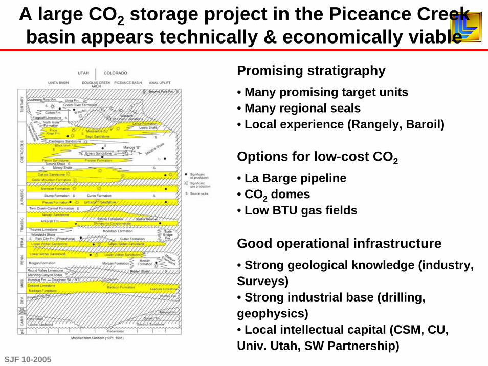
A large CO2 storage project in the Piceance Creek basin appears technically & economically viable
Promising stratigraphy• Many promising target units• Many regional seals• Local experience (Rangely, Baroil)
Options for low-cost CO2
• La Barge pipeline • CO2 domes• Low BTU gas fields
Good operational infrastructure• Strong geological knowledge (industry, Surveys)• Strong industrial base (drilling, geophysics)• Local intellectual capital (CSM, CU, Univ. Utah, SW Partnership)

SJF 10-2005
Viewed from the operators standpoints, there remain uncertainties in operational requirements
Currently, aspects of the likely operating conditions are not clear
A large storage project could provide confidence to key stakeholders and inform decision-makers (regulators, investors, insurers)
Regulatory framework• Only EPA has current authority over any component (UIC, groundwater quality)• No current MMV requirement• Could be EPA or other agency• Unclear definition of due diligence
Liability questions• Uncertainties in attribution, exposure• Unclear what likely duration of liability will be• Decertification will require some transfer of liability
Insurability• Unclear definition of due diligence• No criteria/actuarial tables to rank and risk projects• No Price/Anderson equivalent

SJF 10-2005
Important technical gaps remain before CCS could be widely deployed in key areas
Storage assessments: Piceance, Uinta, Green River basins• Have not quantified injectivity• Don’t know effective pore volume, storage fraction by trapping mechanism• Have not risked prospects by effectiveness
Site-tailored characterization & monitoring programs• High velocity, low porosity• High well density, including abandoned wells
Scope for risk assessment & operational protocols• Wells and faults• Locally magnified risks• In-situ stress; induced seismicity

SJF 10-2005
Outline of large-scale demonstration and experimental projects using low-cost CO2
Basic requirements for a successful large-scale project include both the logistical and scientific aspects, for ~8 years
Small-scale projects cannot deliver the science and technology because of intrinsic questions of scale (e.g., pressure transient and
reservoir heterogeneity effects)
Detailed pre-drill assessment $2-4 MInjection (1-2) & monitoring wells (3-8) $3-8 MCO2 (500,000 – 1,000,000 t/y) $1.5-10 M/yCompression $3-6 M/yMonitoring (multiple methods) $2.2-6.4 M/yAnalysis and modeling $5-7 M/yPost-injection sampling/recompletion $3-8 MTotal $107-225MAnnual $13 – 28 M
Of the current large projects, only one
(Weyburn) approaches these criteria; pending
efforts may come closer, if properly
funded & coordinated
Just the science costs:$30 – 75 M
SJF 10-2005
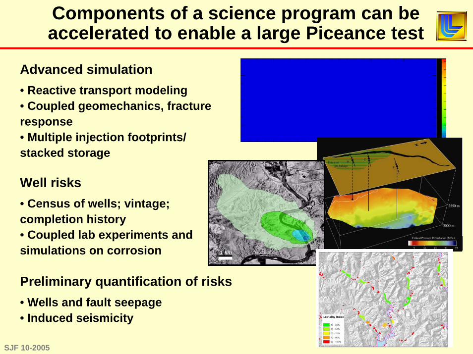
Components of a science program can be accelerated to enable a large Piceance test
Advanced simulation• Reactive transport modeling• Coupled geomechanics, fracture response• Multiple injection footprints/ stacked storage
Well risks• Census of wells; vintage; completion history• Coupled lab experiments and simulations on corrosion
Preliminary quantification of risks• Wells and fault seepage• Induced seismicity
1 km1 km

SJF 10-2005
Competing liquid fuel supplies have already embraced CCS as a cost of business
The US oil shale industry will be delayed or impeded if it is not proactive with regard to carbon management
Coal to liquids• Latrobe Valley Project• Montana, Pennsylvania, Illinois proposals
Heavy oil/bitumen (in Canada)
Ethanol byproducts (e.g., Kansas pilot)
Synthetic natural gas and hydrogen power
SJF 10-2005
Conclusions
Oil shale development and recovery strategies occur in the framework of a carbon-constrained world, where carbon capture and sequestration (CCS) is an enabling technology
The current state of knowledge strongly supports successful deployment of CCS
LARGE SCALE tests are crucial to understanding successful deployment of carbon capture and sequestration (CCS) and creating appropriate policy/economic structures.
No test planned to date is sufficient with respect to scale, duration, monitoring, and analysis.
The map is not the territory – Alfred Korzbyski

SJF 10-2005
Plugs remain a key concern, particularly for old wells (orphaned and abandoned)
http://fotos.naturspot.de/bilder/11-336.html http://www.hardwarestore.com/media/product/221101_front200.jpg
1850’s – 1920’s
• Animal Carcasses
• Mud
• Debris
• Nothing
1930’s – 1953• Mud
• Cement with no additives
1953 – present
• Standard Portland Cement
• Cement with additives
http://www.richardseaman.com/Travel/NewZealand/NorthIsland/Rotorua/MudPools/SunkenMudPool.jpg
Plug technology has improved over time due to regulation
These wells present a challenge to integrity and monitoring which could be resolved through
SJF 10-2005
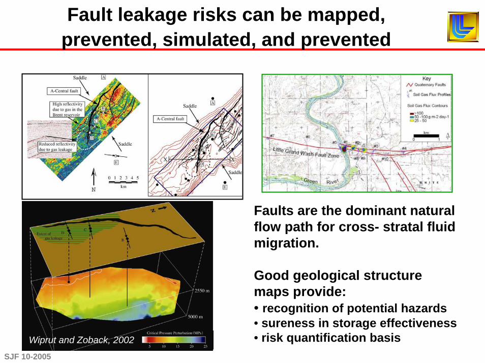
Fault leakage risks can be mapped, prevented, simulated, and prevented
Faults are the dominant natural flow path for cross- stratal fluid migration.
Good geological structure maps provide:• recognition of potential hazards• sureness in storage effectiveness• risk quantification basis Wiprut and Zoback, 2002
SJF 10-2005
To quantify risk, numerical models must integrate complex processes for accurate forecasting
Currently, there is no package that satisfies the full complement of simulation needs.
In order to resolve these key questions, the DOE should implement an intensive, accelerated program to develop and deploy the
simulation capabilities
• Reactive transport, including full geochemistry and dynamic permeability
• Coupled geomechanics/fracture dynamics, including seismic hazard & fault reactivation
• Well components, including plugs, cements, and annulus
• Vadose-zone transport & other environmental hazards
• Outputs usable for risk assessment