in support with synopsys - anveshana.org selection of synopsis and identifying mentees: once...
TRANSCRIPT

Anveshana 2016-17 – Bangalore – Abstract Book 1
In Partnership with
Student Projects Technical Record
Released on the occasion of
Science & Engineering Fair of Selected Projects
At
Shikshakara Sadana, K G Road, Bangalore
On
22nd & 23rd February 2017
Organised by
Agastya International Foundation
In support with
Synopsys

Anveshana 2016-17 – Bangalore – Abstract Book 2
CONTENTS
1. FOREWORD
2. ABOUT AGASTYA INTERNATIONAL FOUNDATION
3. ABOUT SYNOPSYS
4. ABOUT ANVESHANA
5. PROJECT SCREENING COMMITTEE
6. LIST OF PROJECTS EXHIBITED IN THE FAIR
7. PROJECT DESCRIPTION

Anveshana 2016-17 – Bangalore – Abstract Book 3
FOREWORD
Science and Technology are the engines that drive the development and progress of a
country. Science is culture of a society and mostly curiosity driven. Technology,
especially science driven technology, is the one which produces wealth for a country.
In the present interconnected world and globalized economy, country which can
educate its younger population to invent and innovate has a greater chance of
success in capturing the market by providing services and products that others are
willing to pay to acquire the same.
Dr. Michael Mumford, a distinguished professor of Psychology at the University of
Oklahoma, says “Over the course of last couple of decades we seem to have reached
a general agreement that creativity involves the production of novel, useful
products”. The question, therefore, is how to create creativity. Clearly education is an
essential ingredient. Arousing curiosity and building self- confidence to think
unconventionally are other necessary attributes.
Over the last couple decades Agastya International Foundation has experimented
successfully in science education, kindling curiosity, and in building self-confidence
among primary and secondary school children. Among the many innovative ideas
implemented by Agastya, Anveshana is a novel one in which the school children are
coupled with science and engineering undergraduates to design and demonstrate
simple S&T projects. This innovative experiment has led to bidirectional learning of
the children and the undergraduates. The themes selected – ecology, environment,
energy, water resources, robotics etc. – besides being topical have generated many
creative ideas some of which are even implement table as products.
Over the last few years the initial success of Anveshana held in Bangalore has led to
its implementation in a few other cities across India. I feel that the spread of this idea
is going to challenge the spread of wild forest fire.
I wish Anveshana 2016-17 all the success. I would soon like to see it all the cities in
India.
Dr. V.K. Aatre Scientist and Former Head of DRDO

Anveshana 2016-17 – Bangalore – Abstract Book 4
ABOUT AGASTYA

Anveshana 2016-17 – Bangalore – Abstract Book 5

Anveshana 2016-17 – Bangalore – Abstract Book 6

Anveshana 2016-17 – Bangalore – Abstract Book 7

Anveshana 2016-17 – Bangalore – Abstract Book 8
ABOUT SYNOPSYS
Corporate Background
Synopsys, Inc. (Nasdaq:SNPS) provides products and services that accelerate innovation in the global electronics market. As a leader in electronic design automation (EDA) and semiconductor intellectual property (IP), Synopsys' comprehensive integrated portfolio of system-level, IP, implementation, verification, manufacturing, optical and field-programmable gate array (FPGA) solutions help address the key challenges designers face such as power and yield management, system-to-silicon verification and time-to-results. These technology-leading solutions help give Synopsys customers a competitive edge in quickly bringing the best products to market while reducing costs and schedule risk. For more than 25 years, Synopsys has been at the heart of accelerating electronics innovation with engineers around the world having used Synopsys technology to successfully design and create billions of chips and systems. The company is headquartered in Mountain View, California, and has approximately 90 offices located throughout North America, Europe, Japan, Asia and India.
- See more at:
http://www.synopsys.com/Company/AboutSynopsys/Pages/About.aspx#sthash.GSEbLS7
b.dpuf

Anveshana 2016-17 – Bangalore – Abstract Book 9
ABOUT ANVESHANA
Anveshana Program is structured around the concept of mentoring, “catch them young” and “facilitate the inquisitive minds”.
“Mentoring is a process for the informal transmission of knowledge, social capital, and the psychosocial support perceived by the recipient as relevant to work, career, or professional development; mentoring entails informal communication, usually face-to-face and during a sustained period of time, between a person who is perceived to have greater relevant knowledge, wisdom, or experience (the mentor) and a person who is perceived to have less (the protégé)" (source: http://en.wikipedia.org/wiki/Mentorship). The program looks at Involving school students to provide an opportunity to work with engineering students to find solutions for the encountered social problems. The program envisaged to bring together students from various underprivileged schools and Engineering colleges in respective locations in and around Delhi NCR – in a collaborative platform (Anveshana). Engineering colleges will participate as teams with 2 members. The teams will select 2 students from nearby underprivileged schools (Govt. and Govt. aided schools) to mentor them to design and build models or projects around an identified social problem. In the process school children would directly get the opportunity to work together with more qualified under-graduates, and a chance to ‘learn’ the basic principles (along with hands-on skills on diverse products and interesting processes). The interaction with Juries and dignitaries would be a life-time experience for them to cherish. The school students thus will be exposed to entire planning, designing and building process of the models and in turn will get educated in the scientific and engineering concepts behind the models in Anveshana-2016. (www.anveshana.org) Process of Anveshana (Engineering Fair & Competition):
Initial Screening of Engineering College Teams: Concept synopsis based on social
problems and related Engineering solutions are invited from engineering college teams
for pre-screening by the jury.
Screening, selection of Synopsis and identifying mentees: Once selected the teams are
asked to contact local schools with underprivileged status and to form school student
teams to plan, design and make the models, while collaborating and mentoring the high
school students.
Model Creation and Quality Check by Agastya team: Students will create knowledge
networks between them, their peers and with external resource persons to create
conceptual and methodological framework to create the models. Here, Agastya teams
along with assigned senior resource persons (senior educators, engineers etc.) will visit
the colleges to assist the teams conceptually and in the making of the models while
providing inputs including scientific and technological inputs. One of the main reasons

Anveshana 2016-17 – Bangalore – Abstract Book 10
for these visits is to assure the quality of the collaboration and teaching-mentoring-
learning outcomes.
Conceptual- Technological advice from Agastya: Agastya will also help the teams to
establish links between prominent institutions like Indian Institute of Science, Institution
of Engineers, Indian Institute Technology etc. –in case they need any technological or
conceptual inputs.
Anveshana Fair begins: The models thus made will be exhibited in Anveshana
Engineering fair where the teams would be presenting the same in front of an expert
Jury for Judgment. During the fair, students display their research projects, working
models and present their findings orally and through written journals to the Jury (mostly
a team of scientists and educators). The judging process involves series of interactions
on the concepts, methodology and objectives of the projects done by the students.
Delegates attending the fair: After the judging process students from various schools
and delegates representing various institutions are also expected to attend the fair.
Delegates attending the event will include scientists and educators from large number of
institutions across Hyderabad.
Valedictory: Prizes will be awarded at a valedictory function –towards the end of the
fair.
ANVESHANA MILESTONES 2011 - 12 Anveshana launched in Bangalore
2012 - 13 Anveshana 2nd Edition in Bangalore
2013 - 14 Anveshana 3rd Edition in Bangalore
Anveshana Launched in Hyderabad
2014 - 15 Anveshana 4th Edition in Bangalore
Anveshana 2nd Edition in Hyderabad
2015 - 16 Anveshana 5th Edition in Bangalore
Anveshana 3rd Edition in Hyderabad
Anveshana Launched in NCR-Delhi
2016 - 17 Anveshana 6th Edition in Bangalore
Anveshana 4th Edition in Hyderabad
Anveshana 2nd Edition NCR-Delhi

Anveshana 2016-17 – Bangalore – Abstract Book 11
PROJECT SCREENING COMMITTEE
MG Subramanian
MG Subramanian is an Advisor to Agastya International Foundation. He enjoys going around project sites-namely colleges where Anveshana’s projects are in progress interacting with young mentors and younger mentees pointing out the immense opportunities to teach and learn, to wonder and innovate.
He is an engineer from IIT Madras and an PGDM from IIM Calcutta with a long experience in manufacturing, product, business development and Human resources development. He acknowledges the value of a mentorship and attributes all his successes in life to his mentors .He says Anveshana’s success is inevitable!
Dr. H. G. Nagendra Dr. H. G. Nagendra is Professor and Head at the Department of Biotechnology, Sir MVIT, Bangalore. He holds a doctorate degree in Biophysics from IISc, Bangalore, and was a recipient of the BOYSCAST Post-doctoral Fellowship (DST) from Cambridge University, UK. He has 16 years of teaching and 20 years of research experience, and has authored 26 international publications in various journals. His research interests include protein bioinformatics and structural biology of neurodegenerative peptides. He has made more than 54 presentations at various conferences / seminars as an invited speaker, and has conducted more than 32 conferences / seminars / workshops. Dr. M Govindappa
Name: Dr M Govindappa
Qualification MSc, MPhil, PhD, PDF (USA) Research Publications
06 National 52 International
PhD guidance 03 students awarded (6 students pursuing)
Guided for BE, M.Tech and MSc students for their academic project work
Membership For various biotechnology bodies Reviewers For various journals
Editor for International Journal of Multidisciplinary Research

Anveshana 2016-17 – Bangalore – Abstract Book 12
PROJECTS EXHIBITED IN THE FAIR
S.N PROJECT CODE
PROJECT TITLE COLLEGE NAME SCHOOL NAME
AGRICULTURE
1 AS-B-AG-01
SILKWORM EGG COUNTER MS RAMAIAH INSTITUTE OF TECHNOLOGY, BANGALORE
SRI VEVEKA BALA MANDIRA YELAHANKA
2 AS-B-AG-02
A NOVEL BIO PESTICIDE SIR M VISVESVARAYA INSTITUTE OF TECHNOLOGY, BANGALORE
GHS KODIGEHALLI
3 AS-B-AG-03
SOLAR AND LASER BASED FENCING
POOJYA DODDAPPA APPA COLLEGE, GULBARGA
CHANDRAKANTH PATIL MEMORIAL SCHOOL
4 AS-B-AG-04
PREGANACY DETECTION IN ANIMALS
VETERINARY COLLEGE,HASSAN
NETAJI PUBLIC SCHOOL
5 AS-B-AG-05
MULTI TALENTED ROBOT FOR FARMER
VSM INSTITUTE OF TECHNOLOGY, NIPPANI
NEW SECONDARY HIGH SCHOOL
AIR
6 AS-B-A-01
AIR-QUALITY METER SIR M VISVESVARAYA INSTITUTE OF TECHNOLOGY, BANGALORE
SJP PU COLLEGE HIGH SCHOOL
7 AS-B-A-02
ALGAL FILTERS FOR HEAVY METALS
SIR M VISVESVARAYA INSTITUTE OF TECHNOLOGY, BANGALORE
SJP PU COLLEGE HIGH SCHOOL
8 AS-B-A-03
FABRICATION OF STIRLING ENGINE FOR POWER GENERATION
SRI VENKATESHWARA COLLEGE OF ENGINEERING, BANGALORE
SRI VENKATESHWARA CENTRAL SCHOOL
9 AS-B-A-04
DESIGN AND IMPLEMENTATION OF SOLAR THERMOELECTRIC AIR COOLING AND HEATING SYSTEM
SRI VENKATESHWARA COLLEGE OF ENGINEERING, BANGALORE
SRI VENKATESHWARA CENTRAL SCHOOL
10 AS-B-A-05
EMBEDDED CONTROL FOR POLLUTION FREE ZONE
VIDYA VIKAS INSTITUTE OF ENGINEERING AND TECHNOLOGY, MYSORE
VIDYA VIKAS HIGH SCHOOL, MYSURU
11 AS-B-A-06
HARVESTING WIND ENERGY IN TRAINS USING HELICAL STRUCTURE TURBINE
PES COLLEGE OF ENGINEERING, MANDYA
HUDA PUBLIC SCHOOL MYSURU

Anveshana 2016-17 – Bangalore – Abstract Book 13
12 AS-B-A-07
DEVELOPMENT OF SERVICE ROBOT
BASAVAKALYANA ENGINEERING COLLEGE
SHREE SARADAGI ANNPURNEWARI HIGH SCHOOL
ENERGY
13 AS-B-E-01
BIOPOLYMER SOLAR CELL SIR M VISVESVARAYA INSTITUTE OF TECHNOLOGY, BANGALORE
GHS KODIGEHALLI
14 AS-B-E-02
DESIGN AND FABRICATION OF TURBINE USING GENEVA WHEEL MECHANISM
VIVEKANANDA COLLEGE OF ENGINEERING AND TECHNOLOGY, PUTTUR
GOVT. PU COLLEGE HIGH SCHOOL KOMBETTU
15 AS-B-E-03
SOLAR POWERED COOLING HELMET AND MOBILE CHARGING FOR FIELD WORKER
HMS INSTITUTE OF TECHNOLOGY, TUMKUR
GHS KYATASANDRA
16 AS-B-E-04
AUTOMATIC SPEED AND AUTO LIGHT BEAM CONTROL SYSTEM FOR GLARE PREVENTION IN VEHICLES
SHRIDEVI INSTITUTE OF ENGINEERING AND TECHNOLOGY, TUMKUR
KALIDASA HIGH SCHOOL
17 AS-B-E-06
SOLAR BASED AIR COMPRESSOR
GOVERNMENT ENGINEERING COLLEGE, HUVINAHADAGALI
TUNGABHADRA HIGH SCHOOL
18 AS-B-E-07
SMART STORAGE WITH WEB SERVER INTERFACED
JAIN UNIVERSITY- SCHOOL OF ENGINEERING AND TECHNOLOGY, RAMANAGARA
LAWRENCE HIGH SCHOOL
19 AS-B-E-08
SMART ENERGY SAVER AND CONSERVATOR (SESC)
JAIN UNIVERSITY- SCHOOL OF ENGINEERING AND TECHNOLOGY, RAMANAGARA
TWINKLERS SCHOOL
20 AS-B-E-09
WIND MILL FOR GREEN BUILDING
HIRASUGAR INSTITUTE OF TECHNOLOGY, BELGAUM
MORARJI DESAI SCHOOL, NIDASHOSHI
21 AS-B-E-10
MULTI ROTOR WIND MILL HIRASUGAR INSTITUTE OF TECHNOLOGY, BELGAUM
MORARJI DESAI SCHOOL, NIDASHOSHI
22 AS-B-E-11
HHO SYSTEM JAIN COLLEGE OF ENGINEERING, BELAGAUM

Anveshana 2016-17 – Bangalore – Abstract Book 14
23 AS-B-E-12
E-THERMO JACKET POOJYA DODDAPPA APPA COLLEGE, GULBARGA
MAHADEVAMMA B PATIL SCHOOL, SHAKAINAH BAPTIS ACADEMY
24 AS-B-E-13
REGENERATIVE ELECTRO MECHANICAL BICYCLE
VIDYA VIKAS INSTITUTE OF ENGINEERING AND TECHNOLOGY, MYSORE
VIDYA VIKAS HIGH SCHOOL, MYSURU
WASTE MANAGEMENT (SWACCH BHARATH)
25 AS-B-WM-01
ACTIVATED CARBON FROM CORN COB
DAYANAND SAGAR COLLEGE OF ENGINEERING, BANGALORE
DAYANANDA SCHOOL
26 AS-B-WM-02
NUTRACEUTICALS FROM SILK WASTE
SIR M VISVESVARAYA INSTITUTE OF TECHNOLOGY, BANGALORE
GHS KODIGEHALLI
27 AS-B-WM-03
RECLAMATION OF PALM WASTE
SIR M VISVESVARAYA INSTITUTE OF TECHNOLOGY, BANGALORE
GHS KODIGEHALLI
28 AS-B-WM-04
AUTOMATED WASTE SEGREGATOR
SDM INSTITUTE OF TECHNOLOGY, UJIRE
SDM SECONDARY SCHOOL UJIRE
29 AS-B-WM-05
SOLAR POWERED DRAINAGE CLEANER
BHEEMANNA KHANDRE INSTITUTE OF TECHNOLOGY, BHALKI
GHS KHATGAON
30 AS-B-WM-06
PLASTIC TO ENERGY VIDYA VIKAS INSTITUTE OF ENGINEERING AND TECHNOLOGY, MYSORE
SADAVIDHYA HIGH SCHOOL, MYSURU
31 AS-B-WM-07
DRY LEAVES SUCKER AND GRINDER
VSM INSTITUTE OF TECHNOLOGY, NIPPANI
GHS NERLI
WATER
32 AS-B-W-01
DEFLUORIDATION BY LATERITE METHOD
BLDEA'S VP DR PG HALAKATTI COLLEGE OF ENGINEERING AND TECHNOLOGY, BIJAPUR
SHRI B.M PATIL PUBLIC SCHOOL
33 AS-B-W-02
WATER FOR TOTAL HEALTH HIRASUGAR INSTITUTE OF TECHNOLOGY, BELGAUM
MORARJI DESAI SCHOOL, NIDASHOSHI
34 AS-B-W-03
MOBILE WATER PURIFIER SHAIKH COLLEGE OF ENGINEERING AND TECHNOLOGY, BELGAUM
JOSHI's PUBLIC SCHOOL

Anveshana 2016-17 – Bangalore – Abstract Book 15
GENERAL
35 AS-B-G-01
A SUSTAINABLE MODULAR HOUSE USING LEAN CONSTRUCTION TECHNIQUES
BMS COLLEGE OF ENGINEERING, BANGALORE
GGHS LINK ROAD SHESHADRIPURAM
36 AS-B-G-02
IOT BASED MOP CMR INSTITUTE OF TECHNOLOGY, BANGALORE
GHS YEDIYUR
37 AS-B-G-03
SMART ELECTRONIC HELMET SAHYADRI COLLEGE OF ENGINEERING AND MANAGEMENT, MANGALORE
GHS KUMPALA
38 AS-B-G-04
ATTENDANT ROBOT FOR BEDRIDDEN PATIENTS
SIDDAGANGA INSTITUTE OF TECHNOLOGY, TUMKUR
SRI SIDDAGANGA COMPOSITE JUNIOR COLLEGE HIGH SCHOOL
39 AS-B-G-05
HEAD CONTROLLED MOUSE GIRIJABAI SAIL INSTITUTE OF TECHNOLOGY, KARWAR
GHS KARWAR

Anveshana 2016-17 – Bangalore – Abstract Book 16
1. SILKWORM EGG COUNTER
COLLEGE M S RAMAIAH INSTITUTE OF TECHNOLOGY (MSRIT) SCHOOL SHRI VIVEKA BALA MANDIRA, YELAHANKA, BENGALURU PROJECT GUIDE C G RAGHAVENDRA, ASSISTANT PROFESSOR, ECE DEPT., MSRIT COLLEGE STUDENTS AMAR T, HARSHITH R, ECE DEPT., MSRIT SCHOOL STUDENTS VISHWESWARA M, THRIVENI H BHATT, CLASS 9
ABSTRACT
Sericulture is the art of rearing silkworms for the production of cocoons. Production and timely supply of superior quality silkworm seed is essential to sustain sericulture as a commercial crop in competition with other cash crops. Sericulture in India is practiced both in temperate and tropical zones. Silkworm breeds differ because seasons and rearing conditions vary throughout the year. Timely supply of quality seeds requires proper planning of seed production and distribution of the same. It is very important to count the number of silkworm eggs accurately so that farmers can pay accordingly and they should not suffer a loss. In order to generate some statistics, the fecundity and hatching percentage is measured by counting silkworm eggs. This counting is usually performed in a manual, visual, and no automatic form, which is erroneous and time-consuming. The aim of this project is to develop a machine which can automatically count the number of eggs present in an egg sheet through a visual inspection mechanism which involves image processing.
HYPOTHESIS: Fundamental concepts
Digital image processing: Digital image processing is the use of computer algorithms to perform image processing on digital images. As a subcategory or field of digital signal processing, digital image processing has many advantages over analog image processing. It allows a much wider range of algorithms to be applied to the input data and can avoid problems such as the build-up of noise and signal distortion during processing. Since images are defined over two dimensions digital image processing may be modeled in the form of multidimensional systems.
Pre-processing: The success of the algorithm depends on keeping the noise levels in the image to a bare minimum to ensure that noise grains are not misinterpreted as eggs. Also, uniform illumination conditions need to be maintained to achieve accurate counting. The captured image is pre-processed to eliminate any influence of varying illumination and noise on the captured image.
Step 1: The obtained RGB image is converted into grayscale image since the RGB components does not contain any useful information for counting. This also reduces the complexity of the algorithm.
Step 2: The obtained grayscale image might have varying contrast levels, the image is histogram equalised to adjust the intensities of all the pixels to have uniform contrast levels.
Step 3: The equalised image is converted to a binary image using the thresholding method. This is done to reduce complexity of the algorithm, thus reducing the time of computation.

Anveshana 2016-17 – Bangalore – Abstract Book 17
Since the image is already equalised and all eggs of a particular breed of silkworms have similar visible characteristics.
Connected component algorithm: Connected-component analysis is an algorithmic application of graph theory, where subsets of connected components are uniquely labelled based on a given heuristic. Connected-component labelling is used in computer vision to detect connected regions in binary digital images, although colour images and data with higher dimensionality can also be processed. When integrated into an image recognition system or human-computer interaction interface, connected component labelling can operate on a variety of information.
A graph is connected if there is a path connecting every pair of vertices. A graph that is not connected can be divided into connected components (disjoint connected subgraphs). For example, this graph is made of three connected components. A graph, containing vertices and connecting edges, is constructed from relevant input data. The vertices contain information required by the comparison heuristic, while the edges indicate connected 'neighbours'. An algorithm traverses the graph, labelling the vertices based on the connectivity and relative values of their neighbours. Connectivity is determined by the medium; image graphs, for example, can be 4-connected or 8-connected. Following the labelling stage, the graph may be partitioned into subsets, after which the original information can be recovered and processed.
Figure 1: Graph illustrating connectivity
Morphological operation: Erosion
Erosion is fundamental morphological operation which removes the boundaries of an image resulting in the shrinking of the object. This mathematical operation which is applied to binary images. The boundaries of regions of foreground pixels are eroded; thereby areas of foreground pixels shrink in size. The erosion operator requires two inputs i.e., the image which is to be eroded and a structuring element where the structuring element are much smaller than the image being processed. The structuring element can be any shape from simple 3*3 block filter to complicated structures like disk, ball etc.

Anveshana 2016-17 – Bangalore – Abstract Book 18
METHOD:
Image acquisition involves capturing image of the egg sheet under optimum lighting conditions using a camera of suitable resolution, after which various pre-processing operations like median filtering, averaging filter, etc., are applied to smoothen the image and remove noise. Later, the image is converted into binary image. Various morphological operations like erosion, is applied to separate the eggs which are joint. Then we get the total count by applying connected-component algorithm. The count is displayed on the display.
Figure 2: Figures representation (a) Input RGB Image, (b) Grayscale Image, (c) Histogram Equalised Image, (d) Binary Image, (e) Non-Overlapped Eggs and (f) Overlapped Eggs
Hardware:
The working model of our project consists of Raspberry Pi 2 (a credit card sized computer), a camera and a TFT display. The camera takes a picture of the egg laying and sends it to raspberry Pi. The processing of the image and counting is performed by this credit card sized computer and the final count is sent to the TFT display. The mechanical setup helps to move the camera manually and to fix it at a particular height and position. The whole setup runs on DC (5V,1A) and does not consume much of power.
Figure 3: Software flow diagram
Figure 4: Working model

Anveshana 2016-17 – Bangalore – Abstract Book 19
EXPERIMENT:
Table depicts the comparison of
actual count of eggs with the results
obtained using our proposed
algorithm which incorporates
erosion and connected component
algorithm. Five different input test
images containing different number
off eggs are used to test the
efficiency of the algorithm.
SUMMARY:
The proposed algorithm uses a combination of erosion and connected component methods
to count the number of silkworm eggs. From the experimental results it is seen that
efficiency close to 98% is achieved under uniform illumination conditions, thus it can be
concluded that the proposed methodology is an efficient method for quick and accurate
estimate of the number of eggs. Unlike the tedious manual counting the time of
computation to obtain a count is a few seconds which indicate the low complexity of the
algorithm. Thus, faster computation and lower complexity coupled with good accuracy are
the key features that make our project a promising method for automated counting of
silkworm eggs.
Group photo – Mr. C G Raghavendra, Amar T, Thriveni H Bhatt, M Vishweshwara and Harshith R (Left to right)
Images Actual Count
Count Using Our project
Efficiency (%)
1 455 415 91.21
2 534 502 94.01
3 663 621 93.66
4 613 585 95.43
5 593 555 93.59
Average efficiency 93.58

Anveshana 2016-17 – Bangalore – Abstract Book 20
COST: Rs.50000/-
Sl.
No.
Particulars Quantity Cost
(Rs.)
1 Raspberry Pi 3 processor (inclusive of
Memory card & Power supply)
1 4000
2 Raspberry Pi 7” touchscreen display 1 8000
3 Camera - Logitech HD Pro C920 1 10000
4 Developing the physical model (inclusive of
labour charges)
1 14000
5 Stepper Motors and drivers 2+2 4000
6 Connecting cables, LEDs and other
peripherals
- 2000
7 Silkworm Egg sheet 5 1000
8 Field Trips - 3000
9 Misc. - 4000
Total 50000

Anveshana 2016-17 – Bangalore – Abstract Book 21
2. A NOVEL BIO PESTICIDE
COLLEGE SIR M. VISVESVARAYA INSTITUTE OF TECHNOLOGY SCHOOL GOVERNMENT HIGHER PRIMARY SCHOOL , THINDLU PROJECT GUIDE SRINIVAS B.V , DEEPA N, ASHWATHY DAS, GAURAV COLLEGE STUDENTS PAVITHRA S, AMISH NOAH L. J SCHOOL STUDENTS SANMITHA AND UPENDRA (8th STANDARD) HYPOTHESIS
The entomo pathogenic nematodes(EPNs) that are naturally present in the soil
conditions attack the insect pests and come out in multiplied numbers.
We are mimicking the natural process in the laboratory conditions to obtain large
amount of EPNs using silkworm pupa as the host for the same.
The scientific reason behind the infection is, the EPNs present in the soil senses the
carbon dioxide released from the insect pest and then it attacks the pest.
METHOD
Infecting the host insects (greater wax moth and silkworm) with the entomo
pathogenic nematodes.
In vivo mass cultivation of EPNs.
Serial dilution and standardization of quantity of infective juveniles, required to
infect the target insect pest.
Formulation and development of commercially viable bio pesticide.
Testing the efficacy of the final product.

Anveshana 2016-17 – Bangalore – Abstract Book 22
EXPERIMENTS
ISOLATION
Dig the soil up to 15cm depth at 15 places in the same plot. Collect 100 grams of soil from
each place, and mix it. While mixing the soil add water to maintain the moisture condition.
INFECTION (2 days)
Take 6 plastic containers and add 250 grams of soil into each container. Then add 3 galleria worms to all the containers.
INCUBATION (8-10 days)
Place the infected galleria worms on a petri plate, which contains filter paper. During the period of incubation the colour of the galleria worm changes.
WHITE TRAP METHOD
Place a watch glass and filter paper on a petri plate. Place 3-4 galleria worms on the filter
paper, and maintain moist condition on the filter paper.
After 3 days remove the galleria worms and wash the filter paper with distilled water.

Anveshana 2016-17 – Bangalore – Abstract Book 23
FIELD TESTING
It is performed in the green house taking a type of insect called grub nill.
SUMMARY
Through this project we envision to provide a novel bio pesticide for control of white
root grubs which is responsible for the large scale damage.
Entomo pathogenic nematodes are naturally present in the soil.
These are the worms that multiply inside an insect gaining entry by its lethal bite
thereby releasing its symbiotic bacteria which disrupts the cell membrane of the insect
pests.
Once it gains entry into the grub , it multiplies in millions by several cycles of
reproduction thereby producing millions of infective juveniles.
Anveshana 2016-17 – Bangalore – Abstract Book 24
3. SOLAR AND LASER BASED FENCING
COLLEGE PDA COLLEGE OF ENGINEERING, KALBURGI SCHOOL SHAKAINAH BAPTIST ACADEMY, KALABURGI PROJECT GUIDE Dr. S S KALASHETTY COLLEGE STUDENTS NIDHI KULKARNI, ARPITA JOSHI SCHOOL STUDENTS ADITI, SUMEET K (8th STANDARD) ABSTRACT
In order to stop the wastage of crops which is destroyed by the wild animals, we have
designed a new model which can be used as the fencing system which will protect the crops
from the wild animals without hurting them. Solar and laser based fencing system is
operated with the help of microcontroller ,the microcontroller based security system proves
to be a Real time feedback control system which monitors and controls all the activities in
field system efficiently . The present proposal is a model to modernize the agriculture
industries at a mass scale with optimum expenditure.
HYPOTHESIS
LASER based fences can be used to protect farmhouses, farmlands, forest bungalows, etc
from animals. This controls the animals/human by giving siren that teaches them to stay
away from the fence. And by using the camera, images of the intruders can be sent to
owners through GPS and GSM which adds additional value to the security. LASER fences are
economical by the use of solar power and practical solutions to maximize Field Production
through controlled grazing. It is Safe as its output is discrete (not continuous). In a way,
these simulate the job of a cow boy or a forest guard.
METHODOLOGY AND EXPERIMENT
According to recent records, Crops have been destroyed by the invasion of wild animals in
the coastal regions. It has threatened the human life also. The highest crop damage was
recorded from the forest ranges coming under northern circle. According to an intensive
study, the highest damage was during the summer months. To protect the crops from the
invasion of wild animals, the regional people of the affected areas have taken an action and
raised security systems such as electric fencing , solar fencing which gives electric shocks to
the invader that teaches them to stay away from the fence. But they faced some
consequences which led to death of invaders by the shocks given as it is harmful as well the
power used in electric fencing is ILLEGAL. The proposed idea SOLAR AND LASER BASED
FENCING will overcome the drawbacks of above seen methods.

Anveshana 2016-17 – Bangalore – Abstract Book 25
The laser based fencing system is powered by a 12v rechargeable battery. A solar panel is
connected to the battery to charge on day time which can be utilized during night also.
When an intruder interrupts the laser fence, the circuit will act as a closed circuit and due to
this a siren is produced as output. When the laser beam is cut, a message will be sent to the
respective owner through GSM module indicating that there is an intruder in his field which
adds additional security to the system.
PROTOTYPE
EXAMPLE
SUMMARY AND COST

Anveshana 2016-17 – Bangalore – Abstract Book 26
Solar and laser based fencing system is economical and practical solutions to maximize Field
Production through controlled grazing. It is Safe as its output is discrete (not continuous).
This system if implemented will save lot of time, energy and money of the farmers by
automation of the job. A simple modification can also make the system completely
automatic. The system is relatively simple to design and install. As we are using
microcontrollers, this is error free system. It consumes less power and design of fencing
system is, harm-free for animals and humans thus increasing productivity. For one time
investment, cost of this project will be Rs.80000. If produced in mass then it will reduce
considerably.
TEAM PHOTOGRAPH

Anveshana 2016-17 – Bangalore – Abstract Book 27
4. PREGNENCY DETECTION IN ANIMALS
COLLEGE VETERINARY COLLEGE, HASSAN SCHOOL NETAJI PUBLIC SCHOOL, HASSAN PROJECT GUIDE Dr. HEMANTH GOWDA COLLEGE STUDENTS PREETHAM, NARESH, III BVSc & AH SCHOOL STUDENTS SAATHVIK SHARA, SHUBHAM (7th STANDARD) ABSTRACT:
In the present study, the seed germination inhibition technique was applied to diagnose pregnancy in Crossbred cattle. The urine samples collected from six inseminated cows at two months of post insemination served as positive group and the urine from six non inseminated cows served as negative group. In both the cases, the urine was diluted at the ratio of 1:4 with distilled water. In each sterile Petri dish twenty Green gram seeds were taken on the blotting paper and 15 ml of diluted urine was added. For each cow the test was conducted with a replica of two tests. Control test was also carried out with the addition of water only to the Green gram seeds. The Petri dishes were covered with the trays to avoid evaporation. Seed germination inhibition percentage and shoot length were measured after three days. The result revealed that there was significant difference between the three groups in seed germination inhibition percentage and shoot length. It was concluded that the seed germination inhibition technique is useful to detect pregnancy in cows as a simple, non- invasive and economical method. However, season seemed to be an important factor, which could influence the results of the seed germination test. This fact should be considered especially in case of using this test in tropics, because the results could vary under different conditions. Future, estimation of hormones such as progesterone, oestrogen and correlate with seed germination inhibition percentage and shoot length at different trimester of pregnancy is warranted to confirm the present findings. This seed germination test is a reliable technique in detecting the status of pregnancy as well as non-pregnancy with no negative results. Further investigation will be aimed at isolation and identification of the active inhibitory principle and extent of such a metabolite excreted in urine of pregnant cows which influences seed germination, shoot growth needs to be clearly delineated. HYPOTHESIS:
The establishment and maintenance of pregnancy result from complex interaction of the hormones and signaling by the conceptus. Early pregnancy diagnosis is essential for profitable animal husbandry especially in the productive animal species like cattle and buffaloes. METHOD:
The good quality green gram seeds were purchased from the local market. The urine samples were collected from six inseminated cows at two months of post insemination

Anveshana 2016-17 – Bangalore – Abstract Book 28
served as positive group and the urine from six non inseminated cows served as negative group.
The urine samples were diluted at the ratio of 1:4 with distilled water. In each sterile Petri dish twenty Green gram seeds were taken on the blotting paper and 15 ml of diluted urine was added. For each cow the test was conducted with a replica of two tests. Control test was also carried out with the addition of water only to the Green gram seeds. The Petri dishes were covered with the trays to avoid evaporation. Seed germination inhibition percentage and shoot length were measured after three days. EXPERIMENT:
The experiment was carried out using both pregnant and non-pregnant animals’ urine samples. The result revealed significant difference between the three groups in seed germination inhibition percentage and shoot length. Thereby, the seed germination inhibition technique is useful to detect pregnancy in cows as a simple, non- invasive and economical method. SUMMARY:
This seed germination test is a reliable technique in detecting the status of pregnancy as well as non-pregnancy with no negative results. It is a simple, non- invasive and economical method. However, season seemed to be an important factor, which could influence the results of the seed germination test. This fact should be considered especially in case of using this test in tropics, because the results could vary under different conditions. Future, estimation of hormones such as progesterone, oestrogen and correlate with seed germination inhibition percentage and shoot length at different trimester of pregnancy is warranted to confirm the present findings. Further investigation will be aimed at isolation and identification of the active inhibitory principle and extent of such a metabolite excreted in urine of pregnant cows which influences seed germination, shoot growth needs to be clearly delineated.
COST:
The cost involved in carrying out this method is negligible.

Anveshana 2016-17 – Bangalore – Abstract Book 29
Fig: 1 Control Group Fig: 2 Pregnant Group
Anveshana 2016-17 – Bangalore – Abstract Book 30
5. MULTI-TALENTED ROBOT MACHINE FOR ARECANUT FARMING
COLLEGE VSM INSTITUTE OF TECHNOLOGY, NIPPANI SCHOOL GHS NERLI PROJECT GUIDE RAKESH KUMAR G COLLEGE STUDENTS YUVRAJ DHONDIRAM PATIL, ASAVARI PRAFULL DEVALAPURKAR SCHOOL STUDENTS AKASH BANI, PRAJWAL KAMMAR (10th STANDARD)
ABSTRACT:
The people in rural areas of south India like Karnataka and Kerala mainly depend on agriculture for their livelihood. The main crops grown are Areca nut and coconut. For spraying and applying insecticides on the crown and also for harvesting, skilled labourers have to climb manually up the tree. Such a process looks easy, in reality it is a laborious and dangerous task. Arecanut trees attain a height of about 60-70 feet. It is mandatory to climb the trees a minimum of five times a year for a successful harvest - twice for the preventive spray against fungal disease, and thrice to harvest the arecanut.
Only skilled laborers can carry out these farming operations. They have to climb the trees using muscle power. In an acre that has 550 trees, a laborer has to climb a minimum of 100 to 150 trees. As this involves real hard, physical exertion, younger generations of laborers are losing interest, with potentially harsh implications for arecanut cultivation. The spraying is done in monsoon, while harvest time is typically in summer. It requires skill to climb an areca nut tree. Skilled areca nut tree climbers have become scarce and farmers are finding it difficult to spray the insecticides. In this project aimed to overcome these deficiencies by developing a smart multitalented robot for arecanut farming.
This research is useful for climbing and spraying prestige’s on single tree to multi trees in 3600, and observing the crops on the tree by the help of camera and it helps to harvesting like cutting the bunch of arecanut and collecting it in a basket.
HYPOTHESIS:
Multitalented robot machine having different mechanisms that climb the arecanut tree with proper grip and the slider crank mechanism attached to cutting blades gives a proper strokes to cut the bunches of arecanut . The arm used in this robot has ability to move in 3600 .and sprays prestige’s in proper way.
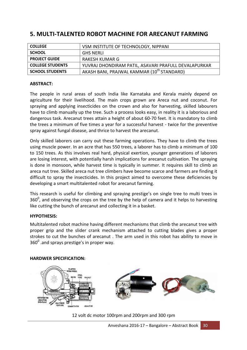
HARDWER SPECIFICATION:
12 volt dc motor 100rpm and 200rpm and 300 rpm

Anveshana 2016-17 – Bangalore – Abstract Book 31
Sprayer nozzle with adjustable diameter 6a DPTD switch
OBJECTIVES:
In an attempt to assist the climbers, an arecanut tree climbing robot has been designed to meets the following goals
It will be controlled from the ground. Both men and women will be able to operate the device. Prestige spraying should be accurate and faster. Robot should able to observe the arecanut very clearly and send live video in
accurate time It will be cut the bunch of arecanut and catch in basket. It will able to land the bunches of arecanut smoothly
For obtain all this goal we have design all necessary mechanism like driving mechanism, body of rob machine ,arm of robot ,nozzle system , basket system ,wheels and blades, cutting mechanism in primary level.
In second stage we have fabricated all necessary components. And assemble it in proper positions and in proper angle to get accurate working and we have to give proper connections to driving mechanism like motor, and controller and also to camera to achieve a high efficient robot machine for arecanut farming.
METHOD
The first step of making “Multitalented robot machine for arecanut farming” is the preparation of the body. GI square pipes and bars are made into sufficient pieces and are welded together to get the body.
Then the wheel is fabricated by using mild still and blades are fabricated by using mild still and rubber are covered over the blades for proper grip .
Then the cutting mechanism is made by using slider crank mechanism and connected to DC motor.
Then we fabricated a robot arm with a spraying nozzle and connected to small motors for obtain 3600 moment and at top of arm we fitted camera.
Then we assembled all this parts in body. And connected to control board and power supply.
By help of weight calculating machine we calculated weight of robot .and by using solar and regular dc current we operated robot and checked the performance of robot, by using trial and error method.

Anveshana 2016-17 – Bangalore – Abstract Book 32
EXPERIMENT
Image of working robot machine
The robot is run by using current from external source or by using solar panel current. This current is supplied in remote control, which controls the motion of motors.
The motors are coupled to wheels of robot in this the trunk of tree acts like rack and wheels are act as a pinion and moment of robot take place. In similar way the robot arm is made for 3600 freedom also coupled with motor and the moment of arm is controlled by remote controller. The cutting mechanism is work on principal of slider crank mechanism and the crank is driven by motor and it’s controlled by remote controller .the position and difficulties capture the camera mounted on robot arm and send it to a mobile. Cutting blades are mounted on slider crank mechanism bar and it cuts the arecanut bunch and it collected in basket that mounted at bottom of robot after finishing work by using remote control slowly we can land robot .and disassemble for next tree .
SUMMARY:
The people in rural areas of south India like Karnataka and Kerala mainly depend on
agriculture for their livelihood. The main crops grown are Areca nut and coconut
For spraying and applying insecticides on the crown and also for harvesting, skilled
labourers have to climb manually up the tree
Such a process looks easy, in reality it is a laborious and dangerous task.
To overcome these problems we developed a robot machine with low cost and user
friendly.

Anveshana 2016-17 – Bangalore – Abstract Book 33
It works on the principle of rack and pinion gear mechanism and slider crank
mechanism.
This research is useful for climbing and spraying prestige’s on single tree to multi trees in 3600, and observing the crops on the tree by the help of camera and it helps to harvesting like cutting the bunch of arecanut and collecting it in a basket.
COST:
S.N Material Quantity Cost Rs =
1 ROBOT BODY
2 Square pipe 1*1 1.5 310
3 m.s. square bar 1*0.2 1.5 260
4 Bearings 4 260
5 springs 4 160
6 Ms bims 0.25*0.25 1 50
7 Spicks belt 20 200
8 Nut,bolts ,screws washer 1 box 500
CUTTING MECHANISM
9 Blades 2 400
10 Square bar 2 70
11 M S plate 2*2* 1 50
SPRYING MECHANISM
12 Arm (squire pipe ) 0.25 30
13 Bearing 1 50
14 Pvc pipe 0.25 10
15 Nozzle 1 50
16 Water pipe 40 250
DRIVERS AND ELCTRONIC AND ROBOTICS COMPONENTS
17 Wiper motor 6 3000
18 Geared motors 5 750
19 Johnson gear motor 1 750
20 Rocker switches 15 460
21 legs 86 172
22 Soldering wire 1 60
23 clamp 2 40
24 Remote box 1 50
25 Big wire 1mm 1 box 580
26 Small wire 1.5 box 300
27 Wire texo 10 100
28 Socket pins 3 200

Anveshana 2016-17 – Bangalore – Abstract Book 34
29 Holding clips 2 60
30 Switch box 1 50
31 Web camera 1 500
32 transformer 1 2500
COLOURING
33 Spry colours 2 0420
TOTAL 12642/-

Anveshana 2016-17 – Bangalore – Abstract Book 35
6. HAND-HELD AIR QUALITY METER
COLLEGE SIR M VISESVARAYA INSTITUTE OF TECHNOLOGY SCHOOL SRI JAGADGURU PANDITHARADYA HIGH SCHOOL PROJECT GUIDE MAHESH DURGALA, SRIKANT M PANCHAL COLLEGE STUDENTS DARSHAN NAIK, NAGASHREE K S, C A SUWARNA, BHAVYA C SCHOOL STUDENTS SABANNA N, KOTRESHA B (10th STANDARD) ABSTRACT
Pollution is one of the major man made threats to themselves. Pollution level varies from place to place. Also presence of some components might not bother some while it may be a risk of life for others. There are many air pollutants starting from dust to poisonous oxides to simple elemental metals. All these are permissible in air in different levels while few are intensely harmful even in small amounts. Our device is an attempt to give instantaneous and reliable data about these varying factors in an easy way and at cheaper cost. Presently this data is recorded and stored by different departments surveyed at different places. This data is stored one and cannot be accessed in time by people. The device is a combination of few sensors that give the data of the pollutants and few components of air that have to be in limited quantity. Since the device is small and portable, people with health issues and other limitations can take better care of themselves by avoiding dangerous places for them.
HYPOTHESIS
The main idea is to develop a reliable Hand-held Air Quality Meter. Then to measure air pollution levels in different areas in and around Bengaluru using this device. Also to compare these values with that of the values generated by Karnataka Pollution Control Board to confirm the reliability of the device.
METHOD
The methods used for this project as a follows:
The microcontroller used here is Arduino UNO.
The components here are MQ2, MQ6, Dust sensor, LCD display.
MQ2 is a CO2 sensor. As the name indicates this sensor reads the carbon dioxide. This is an analog output sensor. This needs to be connected to any one analog pin.
In the program of the Arduino we should read the analog pin of the MQ2 sensor. This value is stored in a integer value to make it a decimal value.
The next sensor is MQ6 sensor. It is highly sensitive to LPG, iso butane and propane. It is also sensitive to alcohol and smoke. This sensor has response; it is also stable and has long life.
This sensor is used to detect the LPG, iso butane, propane, LNG, and alcohol.
The MQ6 athaiye is composed of AL2O3 ceramic tube, tin dioxide, measuring electrode.

Anveshana 2016-17 – Bangalore – Abstract Book 36
MQ6 is also an analog sensor. This is also connected to a analog pin. And the procedure for taking the reading is same as the MQ2 sensor.
The dust sensor is used to detect the dust particles in the air. The dust sensor is used to detect dust, pollen and particles. This sensor has excellent long term reliability and easy maintenance. The sensor is compact in size.
The dust sensor detects the fine particles and measures the quantity of floating particles in a space.
The sensor generates forced inflow of the sampling air and measures the dispersion of reflected light by particles. The measurement is then conveyed into PWM output signal.
The Arduino board reads the value of each sensor separately and then calculates whether the air is toxic or not by the values of the sensor. Different air pollution levels are indicated using RED, YELLOW, and GREEN LEDs.
The LCD display is used here to display the values calculated by the sensors. It shows the quantitative measure of pollution levels.
BLOCK DIAGRAM

Anveshana 2016-17 – Bangalore – Abstract Book 37
EXPERIMENT
We went to the different places in and around Bengaluru and checked for values of CO2,
dust levels, temperature and humidity using our device. In these places we took five
readings at a distance of about 200m to 300m distance and then took the average of them
for average pollution level in that area.
The different places with pollution levels are:
Jalahalli (Medium)
Yelahanka (Medium)
Koramangala (Low)
Peenya (High)
Majestic (High)
Then the team visited “Karnataka State Pollution Control Board, The Central Environment
Laboratory Bengaluru”. There we approached the Air Quality Test Division and verified our
readings with them. We also compared the accuracy level of our readings with the available
readings and there was a slight variation in the readings but still they appreciated our work
and also said that such minor differences were acceptable. Thus Air pollution levels in
different areas were measured successfully using 'Handheld Air Quality Meter'.
SUMMARY:
Our project mainly aims in creating awareness about the air pollution and taking right
precautions. At present, in India there are devices to study the pollution level of CO2, CO
and other pollutants separately. In our project we have put all these together along with the
temperature, humidity, date and time in a single device. Moreover, the devices presently
available are bulky and not portable. Our device is portable device. This helps us to study
the pollution level every day and compare with the previous records. Our device is so simple
that anyone without prior training can easily use it. The device is cost effective and gives us
the accurate values. We can commercialize this device too, to the right customers.
COST : INR 2500/-

Anveshana 2016-17 – Bangalore – Abstract Book 38
7. ALGAE FOR REDUCTION OF HEAVY METAL CONTAMINATION
FROM WATER BODIES
COLLEGE SIR M VISESVARAYA INSTITUTE OF TECHNOLOGY SCHOOL GHPS THINDLU PROJECT GUIDE Ms. PRIYA NARAYAN COLLEGE STUDENTS PRAJWAL SCHOOL STUDENTS SHWETHA R, ROHIT KUMAR (10th STANDARD) ABSTRACT:
Water resources like rivers and lakes are the sources of water that are potentially useful for
everyday purposes like drinking, irrigation and household purposes. Most of the lakes found
in and around Bangalore are contaminated with heavy metals especially those that are used
for irrigation. The heavy metal contaminated water is known to cause a lot of health
problems in humans like anaemia, diarrhea, kidney disease, heart failure, lung damage, toxic
to skin and nervous system and respiratory problems.
Algae have been reported to possess a wide range of bio active properties. In the present
study, algae were isolated from brackish water using Pringsheim’s media with slight
modifications to increase the growth. The growth and biomass content of the algae were
analysed under varied conditions of light and air. The Bioremediation property of the spent
algal culture was exploited by looking at the heavy metal bio absorption. Our results
interestingly pointed out that the algal biomass could clear out a very high concentration of
lead in the polluted Byramangala Lake. It was found from atomic absorption studies (AAS)
that the lead concentration had become nil as against a concentration of 10ppm. The
18srRNA revealed that the algae belonged to Dictyosphaerium sp.
HYPOTHESIS:
Heavy metals are known to cause significant alterations in the plants upon accumulations in
terms of growth parameters and different nutritional parameters such as carbohydrate
content, protein content, vitamin and mineral content etc. Bioaccumulation of metals by
algae appears to be a feasible method for remediating the contaminated water bodies, as
algae may be grown in systems with little nutritional input or less maintenance (N. Abdel-
Raouf et al., 2012).With this background, we surveyed the contaminated lakes in and
around Bangalore, and chose as a case study the Byramangala Lake, which exhibited
increased lead content. Our analysis has revealed that the concentration of lead in the lake
is 0.14 ppm which was about 3 to 4 times higher than the permissible limits. Since this lake
water is being used in an unregulated way for farming and fishing purposes, the
accumulation of lead down the food chain is a matter of grave concern, as it could become
the root cause for several ailments. Higher concentrations of lead can damage various
organs of the body causing neurological, reproductive and kidney malfunctions. It can also

Anveshana 2016-17 – Bangalore – Abstract Book 39
result in high blood pressure and anaemia. Lead is especially harmful to the developing
brains of foetuses and young children. Lead interferes with the metabolism of calcium and
Vitamin D. High blood lead levels in children can cause consequences which may be
irreversible including learning disabilities, behavioural problems, and mental retardation. At
very high levels, lead can cause convulsions, coma and death as well (Anju A. Kumar et al.,
2011, Hasmi, et al., 2014).
With the strong literature that algae are good sequesters of metals, our work initially
involved isolation of microalgae from the waters of the Vembanad Lake, Kerala, which
contained more than 0.1ppm of lead (Anju A. Kumar et al., 2011). This indicates that the
microalgae might have got acclimatised in the lead rich environment. Bio-absorption study
was carried out by mixing equal volume of Byramangala Lake Water with 15 days grown
algal culture for complete interaction. The mixture was kept under shaking for 1 week at
120rpm and subsequently taken for atomic absorption studies. From our results, it was
found that the algae had absorbed lead completely indicating its potential use as
remediation material. To find out the maximum amount of lead that algae can absorb,
distilled water with 10ppm of lead salt was synthetically prepared. After 1 week of
incubation, and further absorption analysis, it was found that the algae had completely
absorbed lead. This algal strain was sent for 18srRNA characterization and it was found that
the species is novel. As per our knowledge, this appears to be the only strain where
absorption of toxic metals like lead was complete, and even at higher concentrations as
well.
Thus, at the end of the project, we intend to develop a cost-effective solution which is the
algal brickets for bio-remediation of selected Bangalore Lakes, to not only replenish our
lakes/water bodies, but also minimize the accumulation of lead and its prevention in
percolating down the food chain. The lead-free water-body could become a safe source for
agriculture/aquaculture/floriculture practices. This will also help in better conservation of
aquatic life and maintenance of the ecosystem balance (healthy habitat for migratory birds).

Anveshana 2016-17 – Bangalore – Abstract Book 40
METHOD
EXPERIMENT

Anveshana 2016-17 – Bangalore – Abstract Book 41
SUMMARY: A concept of “waste to wealth”
We have come across many lakes in and around Bangalore that are contaminated with
heavy metals. These heavy metals possess a threat towards the environment and living
beings. The heavy metals get accumulated in soil and water. The lake water is used for many
purposes including agriculture. The product obtained from agriculture will contain heavy
metals and get into food chain. These have many health-related issues depending on the
type of the heavy metal present in lake. To overcome the problem of heavy metals in lake
water we are focusing on using algae to remove heavy metals from contaminated lake.
Algae have been reported to possess a wide range of bio active properties. In the present
study, algae were isolated from brackish water, using Pringsheim’s media with slight
modifications so as to increase the growth. The growth and biomass content of the algae
were analysed under varied conditions of light and air. The spent culture shall be used to
absorb heavy metal from the polluted lake and it will be analysed from atomic absorption
spectroscopy for the concentration of heavy metal.
COST:
REFERENCE:
N. Abdel-Raouf et al., 2012., Botany and Microbiology Department, Faculty of Science, Medical Studies and Sciences Sections, King Saud University, Riyadh, Saudi Arabia Anju A. Kumar et al., 2011.,Seasonal Variation of Heavy Metals in Cochin Estuary and Adjoining Periyar and Muvattupuzha Rivers, Kerala, India, Global Journal of Environmental Research

Anveshana 2016-17 – Bangalore – Abstract Book 42
8. FABRICATION OF STIRLING ENGINE FOR POWER GENERATION
COLLEGE SRI VENKATESHWARA COLLEGE OF ENGINEERING, BENGALURU SCHOOL S V CENTRAL SCHOOL, BENGALURU PROJECT GUIDE ATMANAND ANIKIVI COLLEGE STUDENTS RAGHAVENDRA R, PARINEET HIREMATH SCHOOL STUDENTS HEMANTH GOWDA K S, PRADEEP C S (9th STANDARD)
ABSTRACT:
A Stirling engine is a heat engine operating by cyclic compression and expansion of air or
other gas, the working fluid, at different temperature levels such as net conversion of heat
energy to mechanical work. The Stirling engine was noted for its high efficiency compared to
steam engines, quiet operation, and the ease with which it can use almost any heat source.
The purpose of the project, are to design and fabricate the Stirling engine.
The performance of Stirling engines meets the demands of the efficient use of energy and
environmental security and therefore they are the subject of much current interest. Hence,
the development and investigation of Stirling engine have come to the attention of many
scientific institutes and commercial companies. The Stirling engine is both practically and
theoretically a significant device, its practical virtue is simple, reliable and safe which was
recognized for a full century following its invention by Robert Stirling in 1816. The engine
operates on a closed thermodynamic cycle, which is reversible. Today Stirling cycle-based
systems are in commercial use as a heat pump, cryogenic refrigeration and air liquefaction.
As a prime mover, Stirling cycles remain the subject of research and development efforts.
The objective of this paper is to provide fundamental information and present a detailed
review of the past efforts taken for the development of the Stirling cycle engine and
techniques used for engine analysis. Several attempts have been made by researches to
build and improve the performance of Stirling engines. It is seen that for successful
operation of engine system with good efficiency a careful design of heat exchangers, proper
selection of drive mechanism and engine configuration is essential. The study indicates that
a Stirling cycle engine working with relatively low temperature with air or helium as working
fluid is potentially attractive engines of the future, especially solar-powered low-
temperature differential Stirling engines with vertical, double acting, and gamma
configuration.
HYPOTHESIS:
Stirling's air engine (as it is referred to in early text books) was invented by Reverend Dr.
Robert Stirling and patented by him in 1816. When the name became simplified to Stirling
engine is not known, but may be as recently as the mid twentieth century when the Philips
Company began to experiment with working fluids other than air. They still refer to it as an

Anveshana 2016-17 – Bangalore – Abstract Book 43
'air engine'. The main subject of that original patent was a heat exchanger which Stirling
called the "economizer" for its enhancement of fuel economy in a variety of applications.
The patent also described in detail the employment of one form of the economizer in an air
engine, in which application it is now commonly known as a regenerator. An engine built by
Stirling was put to work pumping water in a quarry in 1818. Subsequent development by
Robert Stirling and his brother James, an engineer, resulted in patents for various improved
configurations of the original engine, including pressurization which by 1845 had sufficiently
increased the power output for it to successfully drive all the machinery at a Dundee iron
foundry. As well as conserving fuel, the inventors sought to create a safer alternative to the
steam engines of the time whose boilers frequently exploded with dire consequences, often
including loss of life. However, the need for the Stirling engine to run at a very high
temperature to maximize power and efficiency exposed limitations in the materials of the
day and the few engines which were built in those early years had rather short and
troublesome lives.
Although improvements were made to curb up the problem, stiff competition from the
internal combustion engine forced the hot air engine out of the commercial scene. Over the
years, researchers have continued Stirling engines, working out many of the design solutions
that are used today in low temperature differential Stirling engines.
METHOD:
Stirling engine uses the temperature difference between its hot end and cold end to
establish a cycle of a fixed mass of gas, heated and expanded, and cooled and compressed,
thus converting thermal energy into mechanical energy. The greater the temperature
differences between the hot and cold sources, the greater the thermal efficiency. The
maximum theoretical efficiency is equivalent to the Carnot cycle; however, the efficiency of
real engines is less than this value due to friction and other losses. These are distinguished
by the way they move air between the hot and cold sides of the cylinder.
EXPRIMENT:

Anveshana 2016-17 – Bangalore – Abstract Book 44
SUMMARY:
Our Stirling engine model has a good point that they can be constructed in a way that they
produce no emissions. That means, in combination with solar or geothermal heat, they can
be used as a renewable energy source to produce electricity by means of dynamo.
The real renewable energy is the solar application for this device because the other ways to
produce the heat source are burning something. It is possible to decrease the emissions of
CO2 or other toxic gases but not eliminate completely this problem for the earth and
therefore for humans. This application could be one of the different ways to solve the
problem of greenhouse gas emissions and to continue and to develop our comfort. No high-
tech materials are needed.
Future Aspects of our project: Continuous rotation of fan can be used for the generation of
electricity, by providing Dynamo at the shaft of fan.
COST:
The total cost of the model=12000 Rs.

Anveshana 2016-17 – Bangalore – Abstract Book 45
9. DESIGN AND IMPLEMENTATION OF THERMOELECTRIC AIR-
COOLING AND AIR-HEATING SYSTEM
COLLEGE SRI VENKATESHWARA COLLEGE OF ENGINEERING, BENGALURU SCHOOL S V CENTRAL SCHOOL, BENGALURU PROJECT GUIDE ARJUN KUMAR G B COLLEGE STUDENTS YASASWINI PONNAGANTI, RASHMI P SCHOOL STUDENTS YOGESHWAR, GAUTAM (9th & 8th STANDARD) ABSTRACT Solar energy is the world’s most rich, stable and clean source of energy having a large potential. Refrigeration contributes to the emission of CFCs, HCFCs, carbon-dioxide etc. To overcome problem of emission and fulfill the mismatch between the demand and supply of energy consumption the interest in utilization of solar based refrigeration system has increased gradually. The purpose of this project has been to investigate possibility of heating and cooling air by connecting peltier elements to a photovoltaic panel this model compliments to existing heating system in order to pre-heat or pre-cool the inlet of air.
INTRODUCTION Air cooling and Air heating system is an important and basic day to day need, making these system accessible to every individual is something much needed, application of a portable, DC operated and compact size air cooling and air heating system are medical applications, use in remote places, during outdoor events etc. Our aim is to build a prototype of a portable air cooling and air heating system which can cool down up to 10 degree centigrade. OBJECTIVE
Improving air cooling and air heating system efficiency can contribute greatly to reducing
operating costs of The air cooling and air heating system compact size of a module, faster
cooling time and allowed DC power supply will lead the system to be portable
BLOCK DIAGRAM
METHODOLOGY
The cooling effect produced by the system is basically based on Peltier effect. When direct current is passed between two electrically dissimilar materials, heat is absorbed or liberated at the junction. Peltier effect is a temperature difference obtained by applying a voltage

Anveshana 2016-17 – Bangalore – Abstract Book 46
between two electrodes connected to a sample of semiconductor material to create a hot and cold side. Basically the heating and cooling effect is produced because of electron hole present inside the P-N type semiconductor. Thus the electron hole are the heat carrier here in the system same as the refrigerants in conventional refrigerator. The cold side of the Peltier module is kept inside the chamber to be cooled while the hot side is kept outside for removal of heat. DC fan with fins are assembled towards hot side for easy and quick removal of heat. ADVANTAGES
1. Direction of thermoelectric heating pump is reversible by changing the polarity of current, so it can work as cooler and heater too.
2. Thermoelectric module does not have moving part to wear and tear; therefore there is no need of any maintenance.
3. It resists shock and vibration. 4. It can work in too severe or sensitive environment. 5. It does not contain any harmful material like CFCs, HCFCs which can damage
environment. 6. It can be tailored to any size as per the requirement of application.
APPLICATIONS
1. Good for use in remote areas where unavailability of electricity is there. 2. Medical and pharmaceutical industry 3. Military application 4. Science laboratory
CONCLUSION
A solar thermoelectric air cooling and air heating system is designed which can be better for use in remote areas where unavailability of electricity is there and also designed system is good for cooling system with good efficiency. As the system is eco-friendly it can better alternatives for the future use as considering depleting of non-renewable sources.

Anveshana 2016-17 – Bangalore – Abstract Book 47
10. EMBEDDED CONTROL SYSTEM FOR POLLUTION FREE ZONE
COLLEGE VIDYA VIKAS INSTITUTE OF ENGINEERING & TECHNOLOGY SCHOOL VIDYA VIKAS SCHOOL, MYSURU PROJECT GUIDE SWATHI K, ASST.PROF, DEPT OF EEE COLLEGE STUDENTS KARTHIK A, LIKHITHA A S ,KALAI SELVI V, KANNAN M SCHOOL STUDENTS AMULYA, ABDUR-REHAMAN-AFZAL (8th STANDARD)
ABSTRACT:
Of the world's top 20 polluted cities, 13 are in India compared to just three in China. Air
pollution slashes life expectancy by 3.2 years for the 660 million Indians who live in cities,
including Delhi. In China, the corresponding dip is marginally lower at three years. India
being a developing country, the major cities in India is turning to the concrete cities. Now a
day’s human is depending on vehicles by one or the other means. Due to this the air
pollution in the cities are globally increasing. It adversely affects the environment and also
the human being. The most important thing is that the children are mainly affected by the
air pollution. Children breathe more air per pound of body weight, so their exposure to air
pollution is much greater than adults. Children’s organs, including their lungs, develop until
they reach their late teens, usually around the age of 18. In India one survey estimated that
about 35% of children are suffering from respiratory problem due to air pollution. Along
with harming human health, air pollution can cause a variety of environmental effects: Acid
rain is precipitation containing harmful amounts of nitric and sulfuric acids. These acids are
formed primarily by nitrogen oxides and sulfur oxides released into the atmosphere when
fossil fuels are burned. So we have to keep the hospital surroundings to be pollution free
zone. For this intension we have taken a project called ‘EMBEDDED CONTROL SYSTEM FOR
POLLUTIN FREE ZONE’.
HYPOTHESIS:
The atmospheric air moves from high pressure area to low pressure area. Hence in the
pollution free zone i.e. the place which is to be pollution free, the sensors are placed in high
pressure area and low pressure area of pollution free zone. Sensor i.e. MQ135 senses the
pollution level in the pollution free zone and pollution level is compared by Arduino with its
predefined level, if pollution level exceeds its threshold level. This information is send to
traffic police to block the pollution free zone route and provide another alternate route or
specific time. If the pollution level is exceeds critical level with previous measures the silica
gel will activate to absorb pollutant gases. Hence the air pollution in that pollution free zone
is monitored and controlled by the embedded system.
METHOD & EXPERIMENT
Pollution level sensors are placed in high pressure and low pressure area.

Anveshana 2016-17 – Bangalore – Abstract Book 48
Sensors are sense the pollution level and send it to the comparator.
Comparator compares the pollution level and takes the respective measures.
If the pollution level exceeds its threshold level
MEASURES:
The information send to traffic police that to block pollution free zone route & provides alternate route for specific time.
And display the pollution level in LCD.
Activate the silica gel to absorb pollutant gases.
SUMMARY:
The embedded system is monitoring and controlling the air pollution to maintain the pollution level within permissible level with the possible measures.
BENEFITS
This can be implemented in vehicles as pollutant emission controller.
This can be used in hospital for highly important place which should be in pollution free zone.
This can be used as pollutants charging unit in industrial sector.
This can be used as air pollution measuring unit and for controlling and monitoring of air pollution in industries.
ADVANTAGES
1. The most important is air pollution can be control using absorber. 2. It can be adopted easily indoor and outdoor fields. 3. It is environmental safe. Hence no hazards are happen to the environment. 4. Implementation and maintenance cost is reasonable and less.
COST: Cost of the project is Rs 7000 to 8000

Anveshana 2016-17 – Bangalore – Abstract Book 49
11. HARVESTING WIND ENERGY IN TRAINS USING HELICAL STRUCTURE TURBINE COLLEGE PES COLLEGE OF ENGINEERING, MANDYA SCHOOL HUDA PUBLIC SCHOOL, MYSURU PROJECT GUIDE D M SRINIVASA COLLEGE STUDENTS MOHAMED ADNAN KHAN, ABHISHEK R SCHOOL STUDENTS MOHAMMED MALIK DEENAR, MOHAMMED HISHAM (9th
STANDARD)
ABSTRACT Energy resources in our modern fast paced techno- world are fast depleting. Hence a renewable energy source is much required at the moment. Thus researching new and innovative systems in renewable energy sector is an indispensable prerequisite. This paper attempts to explain the generation of clean energy by harnessing the power of wind in moving trains. The scope of this paper concentrates on a new approach to harvest wind power by installing a helical shaped turbines on the roof of the trains which are coupled to a generating unit.
HYPOTHESIS: The world is a resident for about 7 billion people which will be 9 billion shortly.1/3rd of the population i.e., 2.3 billion people have no access to electricity. Moreover, world’s fuel needs are largely met by fossil fuels that are costly, finite and non-eco-friendly as it pollutes the environment and are exhausting at a very faster rate. Hence conservation and tapping of energy from new sources is a much needed aspect all over the world. Renewable energy systems on a large scale are an important step for keeping national and international infrastructures intact, it's also important to understand the scalability of renewable energy solutions. It is widely known and accepted that wind and solar power are the most sustainable energy sources that is available in abundance. New improved innovative methods to harness their power are much appreciated in the present decade. Wind energy has long been used to generate electricity through wind turbines, and has proved to be one of the most reliable renewable sources of energy in many countries of the world. However since there are very few regions in the world that experience windy conditions throughout a year, this method becomes restricted to only a few chosen regions.
India has about 63000 route kilometres of railways and 14,300 trains running every day. Indian railways can generate 1,481,000 MW power every day according to calculations. Indian railways spend 17 percent revenue on the fuel head which is roughly 15000 Crores (150 billion) per annum. When the train runs at an average speed of 50-60 km/hr, it creates an air pressure in the
opposite direction. It compresses the air in the front of it and pushes it to its sides, thereby
creating a vacuum at its rear and sides as it moves forward. To fill up this vacuum a mass of air

Anveshana 2016-17 – Bangalore – Abstract Book 50
flow rushes into the sides and rear of the train. The kinetic energy thus created by the wind
flow induced by the train can be effectively utilized to generate power on a larger scale.
Train Motion and Wind Interaction When the train runs at an average speed of 50-60 km/hr, it creates an air pressure in the opposite direction. It compresses the air in the front of it and pushes it to its sides, thereby creating a vacuum at its rear and sides as it moves forward. To fill up this vacuum a mass of air flow rushes into the sides and rear of the train.
Fig.02. Top view of single compartment implemented with proposed model.
From Fig.02 we can see that four helical wind turbines are coupled to a single generating unit. As train is motion of about 60kmph, same speed wind is created in opposite direction.

Anveshana 2016-17 – Bangalore – Abstract Book 51
This wind will be available for this turbines and power of this wind makes turbines to rotate by the principle of lifting force. As turbines starts to rotate the mechanical power is transferred to the shaft of the generator. As shaft rotates this generates the electricity in the generating unit. Since all four turbines are coupled to the same generating unit, the RPM gained by the generating unit is same as the single turbine RPM but torque developed is four times of the single turbine torque. Since we have higher torque due to four turbines we can use higher capacity generator to generate the electric power.
THEORY OF WIND ENERGY The power in the wind is proportional to the wind speed cubed; the general formula for power in the wind is: P=½𝜌AV³ Where: P - The power available in watts.
𝜌 - The density of air (which is approximately1.2kg/m3 at sea level). A - The cross-section (or swept area of a windmill rotor) of air flow of
interest. V - The instantaneous free-stream wind velocity.
Because of this cubic relationship, the power availability is extremely sensitive to wind speed; doubling the wind speed increases the power availability by a factor of eight.
Any wind turbine or windmill rotor can be characterized by plotting experimentally derived curves of power against rotational speed at various wind speeds; Fig.01 (A). Similarly the torque produced by a wind rotor produces a set of curves such as in Fig.01 (B).
Fig.01 (A) and (B) Efficiency, power and torque characteristics

Anveshana 2016-17 – Bangalore – Abstract Book 52
The maximum efficiency coincides with the maximum power output in a given wind speed. Efficiency is usually presented as a non-dimensional ratio of shaft-power divided by wind-power passing through a disc or shape having the same area as the vertical profile of the windmill rotor; this ratio is known as the "Power Coefficient" or Cp and is numerically expressed as:
Cp =𝑃
½𝜌𝐴𝑉³
The speed is also conventionally expressed non-dimensionally as the "tip-speed ratio". This is the ratio of the speed of the windmill rotor tip, at radius R when rotating at ω radians/second, to the speed of the wind, V, and is numerically:
𝝀 =𝝎𝑹
𝑽
Wind Turbine Design
There are two primary physical principles by which energy can be extracted from the wind. These are through the creation of either lift or drag force (or through a combination of the two).Drag forces provide the most obvious means of propulsion, these being the forces felt by a person (or object) exposed to the wind. Lift forces are the most efficient means of propulsion but being more subtle than drag forces are not so well understood. Lift is primary due to the physical phenomena known as Bernoulli’s Law. This physical law states that when the speed of an air flow over a surface is increased the pressure will then drop. This law is counter to what most people experience from walking or cycling in a head wind, where normally one feels that the pressure increases when the wind also increases. This is also true when one sees an air flow blowing directly against a surface, but it is not the case when air is flowing over a surface. So we are using new type turbines to capture wind energy produced by the moving train. It’s almost using the helix form of turbine blades in different way.
EFFICIENCY CALCULATIONS OF THE PROPOSED MODEL
We know that power in the wind is given by
Cp =𝑃
½𝜌𝐴𝑉³
Average speed of the train is around 50-60 km/h. i.e, 16m/s. Therefore velocity of the wind is 16 m/s Let us consider that proposed models rotor radius is 0.5m. Therefore area is .785m². Now Pw = 0.6*163 *0.785
Pw = 1929.2 Watts

Anveshana 2016-17 – Bangalore – Abstract Book 53
Pw = Power available in wind. So total watt energy in wind is 3130.7 Watts German physicist Albert Betz proved that no wind turbine can convert more than 60% of kinetic energy of the wind into mechanical energy to turn a rotor. Therefore power generated in rotor is 60% of P. i.e, power in rotor = 1929.2 *0.60
Pr = = 1157.5 Watts Where Pr = Power in rotor. In the proposed model rotors of the four turbines are connected to the same generating unit. So generating unit gets same RPM of single turbine, even when it is connected to four turbines but torque will be more. Therefore a four times higher capacity generator can be placed for generation of electricity. According to theoretical calculation power generated in single generating unit is: Pg = 4*Pr Watts Where Pg = Power available in generator. Pg = 4*1157.5 Watts Therefore Pg = 4630 Watts Pg = 4.63 KW By taking the losses to consideration the power generated will reduce as compared to the theoretical value. Normal train consists of around 16 compartments. Therefore if we adapt this model to the whole train then the total power generated is: Pt = Pg * number of compartments Where Pt = Total power generated. Pt = 4.63 * 16 KW Pt = 74.08 KWatts.
CONCLUSION Free accessible energy can be created with the help of this work, which can cater to the growing demands of power all over the world. Such a high power output from trains is really appreciated as it can significantly reduce the power shortage and light up numerous homes in the long run. Thus an alternate renewable green energy in a larger scale is provided by the proposed model. Although the idea of wind power from train persists, this research innovation presents a clean picture with adequate analysis and results to support the concept. India has one of the world's largest railway networks comprising 115,000 km of track over a route of 65,000 km and 7,500 stations and this system can bring about a positive and incredible change in India's power production. The effectiveness of the system has substantially a higher competency over any other conventional wind power system that can be used. This produces sustainable power and is environment friendly as it has no pollution consequences. Therefore positive ramification of this entire research is manifold and will tend to alleviate the major energy crisis problems faced all over the world. FUTURE SCOPE Simulation of proposed model to be conducted to improve the practical building of the model

Anveshana 2016-17 – Bangalore – Abstract Book 54
12. DEVELOPMENT OF SERVICE ROBOT COLLEGE BASAVAKALYANA ENGINEERING COLLEGE, BIDAR SCHOOL SARADGI HIGH SCHOOL, BASAVAKALYANA PROJECT GUIDE KHANDOBA COLLEGE STUDENTS ASHWINI MATAPATI, NANDINI BIRADAR SCHOOL STUDENTS ASHWINI, VANISHREE (8th STANDARD) ABSTRACT:
The robot consists of a wheel-based mobile platform with spinal torso, bi-manual
manipulation system with multi-finger robot hands and robot head. Robot prototype was
designed to see, hear, speak and use its multimodal interface for enhanced communication
with humans. Robot is capable of demonstrating its affective and social behavior by using
audio and video interface as well as body gestures. Robot is equipped with advanced
perceptive system based on heterogeneous sensorial system, including laser range finder,
ultrasonic distance sensors and proximity detectors, 3-axis inertial sensor, stereo vision
system, 2 wide-range microphones, and 2 loudspeakers. The device is foreseen to operate
autonomously but it may be also operated remotely from a host computer through wireless
communication link as well as by use of a smart-phone based on advanced client-server
architecture. Robot prototype has embedded attributes of artificial intelligence and utilizes
advanced cognitive capabilities such as spatial reasoning, obstacle and collision avoidance,
simultaneous localization and mapping, etc. Robot is designed in a manner to enable
uploading of new or changing existing algorithms of emotional intelligence that should
provide to robot human-like affective and social behavior.
HYPOTHESIS:
Human-centered high-tech systems like personal devices are designed to be used by humans in everyday life. Personal devices were recognized in the recent decades as forthcoming technology of modern society that will initiate new Technology revolution like it was the invention and exploitation of the Internet in 90-ies. Robotic scholars and practitioners particularly emphasize humanlike movement, human-like intelligence and human-like communication as necessary features of the future personal robots as the technology of the 21st century.
This device is foreseen to operate autonomously but it may be also operated remotely from a host computer through wireless communication link as well as by use of a smart-phone based on advanced client-server architecture.
This project is been addressed to prototyping of technology platform aimed to develop ambient awareness for human centric indoor service robot with attributes of emotional intelligence to enhance interaction with social environment.

Anveshana 2016-17 – Bangalore – Abstract Book 55
This is also designed for technology platform which is also expected to help in development human-centered service robots to be used at home, in the office, public institutions, etc.
METHOD:
The mobile robot platform is a motorized trolley with two driving, microprocessor controlled wheels and two auxiliary wheels ensuring stability and maintenance of direction of motion. The platform is designed to house a cabinet with two horizontally divided compartments. On the lower level, two 12V 120Ah batteries are placed together with a 12VDC to ~230 VAC adapter/charger, electrical fuses, etc., whereas the upper level houses the control and communication electronics - the “brain” of the device. To unload the actuators of the torso and achieve optimal distribution of masses
The torso of the robot consists of lower and upper part. The upper part carries the robot head and two 6 DOF robot arms with artificial hands. The lower part is a central support pillar ending with a two axis rotation drive with a slewing drive transmission, allowing bending of the upper part of the torso around the horizontal axis in the range [-30, +60] degrees, and turning in the range [-180, +180] degrees.
The bi-manual manipulation system consists of two 6 DOF, 5 kg payload universal robot arms UR5 of industrial quality. Each arm is equipped with a three-fingered Barrett-type robotic hand grasper. Two-arm manipulation system, combined with ability of bending the torso, provides good manipulation properties of the overall system. The universal robot hands UR5 possess compliant joints facilitating the interaction with the man without risks of injury.
The robot head contains: kinematic mechanism with 3 DOF, actuated by three DC electric motors with slewing drive transmission, two industrial-grade cameras for robot vision, two wide-band professional-grade microphones with increased sensitivity, and optional visual depth sensor placed on the crown of the head. The head has good kinematic abilities of rotation about three axes: vertical, frontal.
EXPERIMENT
The robot structure consists of several functional modules: wheel-driven mobile robot
platform; segmented torso; bi-manual robotic system with three-fingered graspers;
movable robot head; sensory-acquisition system; and control and communication module.
The adopted system structure, as displayed in Figure 1, allows fine system mobility in
different indoor environments. When determining robot dimensions, human proportions
have been partly taken into account, since it has been planned to use the robot in space
where people live and work and the robot is expected to cooperate with people in particular
tasks. Overall dimensions of the mobile platform, including wheels are L x W x H = 0.70 x
0.70 x 0.72 m. The torso is placed so that the shoulders are on the level of 1.5 m and the
span between shoulders is 0.475 m, which corresponds to human proportions. The size of
the robot head, from chin to crown is 0.26 m and it is proportional to the width of the torso,

Anveshana 2016-17 – Bangalore – Abstract Book 56
whereas the width of the head comes out of proportion due to the need of installing quality
microphones at the position of ears. Such defined dimensions of the robot allow its easy
passage through the standard.
SUMMARY:
The key objective of the project presentation regards to building advanced technology
platform for research and development of personal robots aimed to use for different
purpose, e.g. robot-entertainer, battler, robot for medical care, security robot, etc. In a
word, the designed technology platform is expected to help in development human-
centered service robots to be used at home, in the office, public institutions, etc.
COST: 20,000/-

Anveshana 2016-17 – Bangalore – Abstract Book 57
13. BIO POLYMER SOLAR CELL COLLEGE SRI M VISVESVARAYA INSTITUTE OF TECHNOLOGY, BENGALURU SCHOOL SJP PU HIGH SCHOOL PROJECT GUIDE MAHESH DURGALE COLLEGE STUDENTS U VINISHA, NANDINI K MURTHY, ROOPASHREE V, SAHANA SCHOOL STUDENTS AMBAREESHA N, SUDEEP (9th STANDARD)
ABSTRACT
Plant pigments like chlorophyll, xanthophyll etc. have the property of ejecting electrons
when a light of suitable wavelength incidents on it. A biopolymer extracted from acacia
plant called Gum Arabica is a very effective conductor comparable to super ionic
conductors. A combination of these two materials, solar radiation and potential difference
generates electrical energy. Moreover, there are no devices based on solar radiation that
employ biological sources to produce energy. The sources used here are biodegradable and
easily available thus making it more environments friendly and economic.
HYPOTHESIS
The photosensitization property of chlorophyll combined with the conducting property of
biopolymer is going to generate electrical energy when solar radiation incidents it and when
potential difference is applied.
METHOD
1) Chlorophyll is extracted from leaves and mixed in equal proportions with the
electrolytes.
2) Biopolymer extract is prepared using Gum Arabica.
3) Electrodes are placed on either sides and placed under the sun.

Anveshana 2016-17 – Bangalore – Abstract Book 58
EXPERIMENT
The solar cells are placed under the sun for output,
1) It is first tested without chlorophyll, then with chlorophyll, then under normal Room light, then under dark etc.
2) Later it is tested for various different areas of the base glass used to find out the dependence of current produced on area of exposure.
The following pictures depict the experimental voltage and current ranges under light
At 200millivolts, the multi-meter reading shows high (high==1)
At 2V, the multi-meter reading shows 0.474Volts

Anveshana 2016-17 – Bangalore – Abstract Book 59
At 2mA, The multi-meter reading shows 0.309Milliamps
SUMMARY
The basic model was prepared to test the working of the idea. Since it has given the
expected results, further work is being done to enhance the model to bring about a fully-
fledged working prototype. Many such cells will be connected accordingly to produce a
considerable amount of electricity.
Thus, the electrical properties of naturally available material can be used to produce
electrical energy given with the necessary conditions.
COST: Rs.5000-Rs.7000

Anveshana 2016-17 – Bangalore – Abstract Book 60
14. DESIGN AND FABRICATION OF TURBINE USING GENEVA WHEEL
MECHANISM
COLLEGE VIVEKANANDA COLLEGE OF ENGINEERING & TECHNOLOGY, PUTTUR
SCHOOL GOVT. PU COLLEGE, HIGH SCHOOL KOMBETTU PROJECT GUIDE SUNIL B LAKKUNDI COLLEGE STUDENTS ABHISHEK ACHARYA, PRATHVIK ALVA SCHOOL STUDENTS SANATH RAGHAV, PRATHEEK RAJ (10th STANDARD)
ABSTRACT
We aim at designing and testing a new innovative design of turbine by using Geneva wheel mechanism. Here the turbine will be partially immersed in the openly flowing water. The axis of rotation of turbine is normal to the flow of water. All the blades are always immersed in the water throughout its working.
HYPOTHESIS
This turbine could be further tested by changing minor designs or adding more number of blades for obtaining maximum power output. This turbine is especially designed for canal or rivers where constructing dam and obtaining the minimum water head is difficult. This turbine does not require dam and penstock.
METHOD The turbine consist of five blades whose cross-section is having aero foil shape. The five blades are coupled to the common shaft using links. Blades are connected to link using bearing. The blade is given with intermittent rotation about its own axis with the help of Geneva wheel. Four blades consist of Geneva wheel integrated into it separately. The rotation of the Geneva wheel or blade is directed by the pin fixed to the frame. The experiment setup is directly immersed in the river water. The water flowing energy will exert force on each blades of the turbine. With the help of Geneva wheel the blades are positioned such that all blades will tend the turbine to rotate in single direction. The power is taken out through the central shaft.
EXPERIMENT The Experiment conducted on the model revealed the result of power output. Experiment was conducted using canal water
S.N Speed(rpm) Torque(Nm) Power(W)
1 11 2.5 2.88
2 9 2.09 2.0

Anveshana 2016-17 – Bangalore – Abstract Book 61
SUMMARY We see the power generation is very low for implementation; hence further work must be done on the project to improve the power output.
COST: Rs. 16000

Anveshana 2016-17 – Bangalore – Abstract Book 62
15. SOLAR POWERED COOLING HELMET & MOBILE CHARGING FOR
FIELD WORKER
COLLEGE HMS INSTITUTE OF TECHNOLOGY, TUMKUR SCHOOL GHS, KYATHASANDRA PROJECT GUIDE MOHSIN KHAN A, ASST PROF, ECE DEPT. COLLEGE STUDENTS PRAKSAH M, NAWAZ ULLA SHAIK SCHOOL STUDENTS DHANUSH, KISHAN (8th STANDARD)
ABSTRACT
Solar panels make use of renewable energy from the sun, and are a clean and environmentally sound means of collecting solar energy. The aim of this project is to design solar cooling Fan helmet for people working outdoors. It helps to prevent sunstroke and lowers the temperature and keeps the workers cool by providing gentle and agreeable breeze during their work. The solar cell transfers solar energy directly into electric power which is stored in the battery to turn on the fan. The helmet is simple, light weight and comfortable to wear and a female USB connector is provided in this Helmet to charge the mobiles.
HYPOTHESIS
The survey for similar projects revealed no such simple, light weight and low cost helmet
using solar panel for the purpose of providing cooling facility for the field workers is
designed. In view of health grounds to field workers and to protect workers from hot sun
light this project is developed.
METHOD
Fig: Block diagram of the solar powered cooling Helmet

Anveshana 2016-17 – Bangalore – Abstract Book 63
The figure above shows the block diagram of the solar power cooling Helmet. The Solar panel is placed above the Helmet. Solar panel carries Photovoltaic cells make use of the renewable Energy from the Sun. Solar cells directly transfers into Electric Power, This Electric Power is regulated by using voltage regulator and stored in the Battery. The output of the battery is given to another voltage regulator. The regulated power is supplied to the fan and USB port. An ON/OFF switch is provided for user controlled operation.
EXPERIMENT
Solar panel held above the helmet, the panel capacity is 12V, it produce 100mA and 1.2Watt
in normal sun light. It produces more than 12V in high temperature (sun light).
The output of the solar panel is connected to the voltage regulator (dc to dc converter). It
regulates the voltage from 12v to 9v.
This regulated power is stored in the battery, the battery can store 9v, and the life span of
this battery depends on the LOAD.
The power from the battery is regulated by using another voltage regulator, which regulates
the voltage from 9v to 5v which is given to load. The load is Fan and USB port. The manual
control switch is provided to control the Fan. 800mWatt required to run the fan.
USB ports (5v):
I. USB LED light
II. USB FAN
III. USB Mobile chargers
IV. All USB Applications
SUMMARY
It's good for preventing sun stroke & lowering the temperature for field workers. It comes
with solar panel on top and low noise fan so that user is not disturbed. In this Helmet a USB
connector is provided for mobile charging for field worker. This helmet is useful for field
workers (labors) and Mountain Climbers (trekker’s). It is very Environment Friendly. It is
Simple, light weight and low cost.

Anveshana 2016-17 – Bangalore – Abstract Book 64
Prototype
COST
List of materials required and cost: SOLAR POWERD COOLING HELMET
S.N MATERIAL SPECIFICATION NO’S COST
1 Solar panel 12 v 1 250
2 Helmet 1 150
3 Battery 9 v 1 320
4 Voltage regulators
(dc to dc converters)
I/p=50 v O/p=50 v to 0
v
2 260
5 Fan 5 v 1 230
6 USB socket 5 v 1 10
7 Wire 50
8 others 230
Total 1,500/-

Anveshana 2016-17 – Bangalore – Abstract Book 65
16. AUTOMATIC SPEED AND AUTO LIGHT BEAM CONTROL SYATEM
FOR GLARE PREVENTION IN VEHICLES
COLLEGE SHRIDEVI INSTITUTE OF ENGINEERING & TECHNOLOGY, TUMKUR SCHOOL KALIDASA HIGH SCHOOL, SIRA GATE PROJECT GUIDE HARISH L COLLEGE STUDENTS VIDYASHREE C K, VIDYASHREE B S, KAVITHA S J, SUMA R SCHOOL STUDENTS TEJAS, CHETAK (9th STANDARD)
ABSTRACT
Driving support systems aid in improving the road safety. There are various safety measures
on the road like traffic signals, sign boards and humps to avoid possible accidents. To control
the speeding in motor vehicles on busy and accident prone areas a device is mandatory to
avoid vehicle accidents due to over speeding. Commonly road humps are laid at service road
junctions. Speed humps are used in locations where very low speeds are desired and
reasonable. The aim of this project is to develop automatic vehicle system that detects and
indicates the presence of road humps to the driver to avoid accidents. It also detects and
reduces the speed of the vehicle based on the sign board reorganization present along the
road side for safety purpose. This project also presents the design and development of an
automatic automobile headlight switching system. Headlights of vehicles are inherent for
night driving. These bright headlights which assist the driver for vision, while driving at
night, pose a great threat to the other road users coming in the opposite direction. The
bright light of the vehicles causes a discomfort in the form of a glare to the oncoming driver.
As a rule in night driving, every driver is expected to switch their headlights from high beam
to low beam once they spot an oncoming vehicle within 150 metres in order to reduce the
glare, but this practice is hardly adhered to. This is one of the major causes of accidents
during the night, as the opposing driver will not be able to see the road clearly due to the
brightness of the oncoming vehicle's lights. This automatic headlight switching system
switches the high beam lamp to low beam as soon as it senses a vehicle approaching from
the opposite direction and switches it back to high beam when the cars pass each other.
HYPOTHESIS:
India, the second most populous Country in the World and a fast growing economy, is
known to have a gigantic network of roads. Roads are the dominant means of
transportation in India today. However, most of the roads in India are narrow and congested
with poor surface quality and road maintenance needs are not satisfactorily met. No matter
where you are in India, driving is a breath-holding, multi-mirror involving, potentially life
threatening affair. Roads in India normally have speed breakers so that the vehicle’s speed
can be controlled to avoid accidents. However, these speed breakers are unevenly
distributed with uneven and unscientific heights. According to the survey report “Road

Anveshana 2016-17 – Bangalore – Abstract Book 66
Accidents in India, 2011”, by the ministry of road transport and highways, a total of 1,42,485
people had lost their lives due to fatal road accidents. Of these, nearly 1.5 per cent or nearly
2,200 fatalities were due to poor condition of roads. To address the above mentioned
problems, a cost effective solution is needed that collects the information about the severity
of potholes and humps and also helps drivers to drive safely. In the proposed work, an
attempt to achieve the detection of humps is made. through a single image. The camera is
fixed at low height to the moving vehicle and the image is captured at a constant time
period. This saves memory by storing only the images instead of video and then generating
the video from the single image to view the details on the road before reaching the hump
and act accordingly, only when need arises.
Our universe is filled with different kinds of rules or laws such as physical laws,
environmental laws etc. Similarly we have created a set of traffic rules, to guide the people
travelling and to regulate the traffic flow. Some of these traffic rules are indicated using the
sign boards positioned by the sides of the roads. There are different kinds of sign boards
used such as stop sign, speed-limit sign, warning sign and guide sign. These sign boards are
designed in such a way that by looking at them the driver could extract the information
from it. The driver requires all kinds of information while travelling. A driver does multiple
tasks while he is driving such as, monitoring the road path ahead, observing the vehicles
around him, constantly checking the blind spots, indicating the lane changes and keeping in
track with the traffic rules. Thus the driver is overburdened while driving. The speed limits
on the freeways and other city roads are different. The work zones have different speed
limits. In some locations speed limits are different for day timings and night timings. So in
order to follow the traffic rules the driver has to look for the speed limit signs located by the
sides of the roads. If the vehicle is equipped with the automatic speed detection system it
would detect the speed- limit signs, recognizes them and displays the speed limit
information right in front of the driver. This system would also be helpful to warn the driver
if he is driving much faster than the assigned speed limit. By interconnecting the speed
detection system and the cruise control system, the cruising speed could be automatically
chosen.
The requirement of headlight is a necessity during night travel. The same headlight which
assists the driver for better vision during night travel is also responsible for many accidents.
The driver has the control of the headlight which can be switched from high beam (bright)
to low beam (dim). During pitch black conditions where there are no other sources of light,
high beam is used while on all other cases, low beam is preferred. In a two-way traffic,
vehicles ply on both sides of the road, so when the bright light from the headlight of a
vehicle coming from the opposite direction falls on a person, it glares him for a certain
amount of time, causing disorientation to that driver. This discomfort will result in
momentary involuntary closing of the driver’s eyes. This fraction of distraction is the prime
cause of many road accidents at night. This prototype reduces this problem by actually

Anveshana 2016-17 – Bangalore – Abstract Book 67
switching the bright headlight of the vehicle to low beam automatically when it senses a
vehicle at close proximity approaching from the other direction and switching it back after
the vehicle passes. The entire working of the dimmer is an electronic circuitry arrangement
which senses and switches the headlight according to the required conditions.
METHOD
Figure1.1: Block diagram for sign board detection
Figure1.2: Block diagram for humps detection
Figure 1-1 shows the global view of the automatic speed detection system. A camera
mounted on the rear view mirror of the vehicle is used to capture the traffic scenes that
appear in front of the vehicle. Each traffic scene is processed in real-time using the proposed
algorithm to detect the speed- limit sign board present in it and to extract the speed-limit
information from it. The extracted speed-limit information is displayed on the dash board of
the vehicle and it is given to the cruise control to limit the speed.
MC
Control the
speed
Image Conversion
RGB to Gray scale
Image Captured
Humps Detected
Noise reduction Edge Detection Image
Transformation

Anveshana 2016-17 – Bangalore – Abstract Book 68
Figure1.3: Block diagram for auto light beam control
Figure 1.3: shows a block diagram of auto light beam control. Automatic high/low beam
system is a system which can switch between high and low beam automatically in response
to the detection of light from the oncoming traffic light.
EXPERIMENT
SUMMARY
By implementing this project we can avoid the road accidents during night time and it also
prevents glaring effect which is caused due to high light beam and also we can control the
speed of the vehicle in school zone, hospital zone.

Anveshana 2016-17 – Bangalore – Abstract Book 69
COST
S.N NAME OF THE COMPONENTS UNIT COST
1 Raspberry Pi 1 2800/-
2 Raspberry Pi Camera 1 1200/-
3 Memory Card 1 260/-
4 Battery 1 1250/-
5 Wheels and DC motor 4 each 800/-
6 Miscellaneous 2000/-
Total 8310/-
TEAM PHOTOGRAPH

Anveshana 2016-17 – Bangalore – Abstract Book 70
17. SOLAR BASED AIR COMPRESSOR
COLLEGE GOVERNMENT ENGINEERING COLLEGE, HUVINAHADAGALI SCHOOL TUNGABHADRA HIGH SCHOOL, HUVINAHADAGALI PROJECT GUIDE PROF. MANJUNATH YADAV S, DEPT OF MECHANICAL ENGG. COLLEGE STUDENTS SUBHASCHANDRA, SARFARAZ AHAMED A S, NAGARAJA
U,SHIVANGOUDA S P SCHOOL STUDENTS RUSHANK R, RAVITEJA P (9th STANDARD)
ABSTRACT
We use solar energy in many ways. All day, we use sunlight to see what we’re doing and where we’re going. Solar energy is free and clean. There is enough for everyone, and we will never run out of it. Solar energy is renewable. The sun will keep making energy for millions of years. Why don’t we use the sun for all our energy needs? We don’t know how to yet. The hard part is capturing the sunlight. It shines all over the earth and only a little bit reaches any one place. On a cloudy day, most of the light never reaches the ground at all.
The basic set up of a solar power air compressor is a number of solar panels that are made up of photovoltaic cells. The cells create direct current electricity through the reaction of photons with silicon dioxide. This direct current is used to power a motor that works the compressor unit. It can also be used to charge a battery bank (Lead acid battery) that can be used as a backup when the sun is not shining or at night. This process started from the literature survey. Some of the papers reviewed were “Dynamically self-inflating tire system”. Accordingly a PIC microcontroller is used in this project. Micro controller has the input modules like pressure sensor, control buttons and output modules are LCD display, compressor switching driver and buzzer to give alarm in case of high pressure. Keywords: PIC microcontroller, Pressure sensors, LCD display, Compressor, Buzzer.
HYPOTHESIS
With the existing push in the direction of sustainable, clean sources of power, it is no surprise that solar power has become one of the most popular alternative energy sources. Free and available everywhere, the power of the sun can be employed to power everything like cell phones and motors. The sun's energy is usually harvested through solar panels that are made up of photovoltaic cells. These cells can convert the sun's power into electricity that can be used for a number of purposes. For private use, a handheld solar hybrid charger can be employed to recharge little device for instance a DC fan, a cell phone, or a camera. This project consists of Microcontroller based control unit that continuously monitors and controls the air pressure. This live pressure value gets display on Alpha Numeric LCD display in real time.Regulated output of Solar cell is connected to rechargeable battery through a unidirectional current flow circuitry. This particular charged battery output given as input to the air compressor motor, this motor will controlled by the user manually using control buttons and also automatically by micro controller by a set point. In this project micro controller has the input modules like pressure sensor, control buttons and output modules are LCD display, compressor switching driver and buzzer to give alarm in case of high pressure.

Anveshana 2016-17 – Bangalore – Abstract Book 71
EXPERIMENT
WORKING PRINCIPAL
The photons or solar energy from the sun are trapped by the photovoltaic cells present in the solar panels. It is made to flow in a unidirectional way to the battery such that the battery does not discharge back. The battery is connected to switching circuit which finally drives the air compressor by turning it on. On the other hand, the switching circuit is made to work on the basis of the instructions given from the PIC microcontroller, which is the heart of the project. The pin 1 of the microcontroller is connected to the control buttons. The pin 9 and 10 are attached with crystal oscillator, the purpose of external crystal oscillator is to speed up the execution part of instructions per cycle and here the crystal oscillator is having 20 MHz frequency. One of the regulated power supply circuit is used to control the flow of input voltage to the microcontroller. LED and LCD indicators are used in the 27 and 21 pin position of the PIC microcontroller. LCD displays intensity is controlled by the LCD intensity controller. The pressure sensors are also connected to sense the pressure of the tire to be inflated. If the pressure is found to be maximum then the buzzer beeps making a sense to reset the circuit, Such that the whole project model comes to its initial conditions.
SUMMARY: This project is useful for Oil Industries, Gas Industries, House hold applications, Paint Spraying, Lubrication
COST – INR 4000

Anveshana 2016-17 – Bangalore – Abstract Book 72
18. SMART STORAGE WITH WEB SERVER INTERFACED
COLLEGE JAIN UNIVERSITY –SCHOOL OF ENGINEERING & TECHNOLOGY SCHOOL LAVRENCE HIGH SCHOOL PROJECT GUIDE VINAY KUMAR S B, ASST PROF, ECE DEPT COLLEGE STUDENTS DEEPU DHARSHAN S, ACHUTHA B L SCHOOL STUDENTS C A SARANYA, ULLAS S SHEKAR (7th STANDARD)
ABSTRACT
A smart storage with web server interfaced (SSWSI) is the new trend which takes leap and
puts effort in saving lives. It works by connecting all devices together to give the required
stock update. This can be used in many places where stock can’t be updated manually and
given to the customers. Our product will make this happen which maintains a healthy
relationship between customers, retailers and the production house.
HYPOTHESIS
The smart storage with web server interfaced (SSWSI) is designed to overcome the present method which we consider to be traditional. Traditional method is the manual updating of stocks which isn’t retailer or consumer friendly. Our product is designed in such a way that the stocks are auto updated with least human interaction.
METHOD
The present system is intended to provide the facility of auto-stock update of item whenever any item is sold (actually taken from refrigerator), like blood bottle to server database, which can be accessed by other customers through web around the clock.
The refrigerator area where blood bottle are kept is fitted with object detecting sensors, whose job is to intimate the Object Detector Unit about the presence of the blood bottle. When any blood bottle is taken out of refrigerator the corresponding place sensor detects it and NO Object signal is sent to Object Detector Unit. This Object Detector Unit in turn generates suitable PC’s software understandable alert message and fed it to PC through proper Interfacing Stage. In PC, the memory inherited software module updates the data received on its input port. Thus the blood bottle data base is updated till time automatically. This updated PC data base can be accessed by retailer’s customer from anywhere in world through server.
BLOCK DIAGRAM

Anveshana 2016-17 – Bangalore – Abstract Book 73
EXPERIMENT
1>SENSORS: These field sensors are fitted in Refrigerator where blood bottles are stored, one for
each bottle. They are object sensors and if not found any object in front of them, they produce NO
Object signal which is fed to Object Detector Unit for further processing.
2>OBJECT DETECTOR UNIT: This unit generates NO Object alert signal corresponding to field sensors
signal, which is server’s software format. This server understandable alert signal is fed to input port
of server through suitable Interfacing stage. [Not shown in diagram].
3> INTERFACING STAGE: As server needs TTL compatible level signals at its input port, suitable
interfacing stage must be introduced before feeding field signals directly to it to avoid any kind of
damage.
4>PC: The Monitoring unit of this system has software module in its memory, which will be always in
monitoring mode and scans its input port for any update alert signal. If any such signal found, it
automatically deducts the blood bottle database for one less. So after every pre-determined time
interval this updated data base is further send to Server, where user/owner’s website is situated for
other customer’s information.
5>SERVER: This unit keeps the retailer’s website in its memory bank and allows retailer to access it
from remote end & to other retailer’s customers through router. [This is just for explanation, not
part of project].
6>POWER SUPPLY UNIT: This specially designed regulated power supply unit provides all necessary
voltages to system for proper working.
SUMMARY

Anveshana 2016-17 – Bangalore – Abstract Book 74
The product is simple in design with low power consumption and its compact in size
considering hardware. SSWSI is high reliable, due to the usage of power semiconductor
devices in hardware.it has greater control range due the usage of Personal Computer and its
data base with web connection. So we conclude telling that SSWSI will surely be the faster
version for getting stock updates for customers and retailers.
COST -The approximate cost of our product is 13000 INR.

Anveshana 2016-17 – Bangalore – Abstract Book 75
19. SMART ENERYGY SAVER AND CONSERVATOR
COLLEGE JAIN UNIVERSITY –SCHOOL OF ENGINEERING & TECHNOLOGY SCHOOL TWINKLERS SCHOOL, NETTIGERE GATE, KANAKAPURA PROJECT GUIDE VINAY KUMAR S B, ASST PROF, ECE DEPT COLLEGE STUDENTS ABHINAV MISHRA, MONICA B V SCHOOL STUDENTS PRADHYMNA C K, NIKHIL N IYER (9th & 8th STANDARD)
ABSTRACT
A Smart Energy Saver and Conservator (SESC) is a smart idea that will generate power and
save it. In this project I am proposing a idea of generating electricity and conserving it. This
device will generate electricity from water running down and up through pipes placed in
huge buildings. The Smart Energy Saver and Conservator proposed acts as multipurpose
device because the same device can be used for domestic, commercial and industrial
application.
HYPOTHESIS
Smart Energy Saver and Conservator will generate and store the electricity for future use
and operation. Water tanks are always placed on the top floor, huge buildings have many
floors. So when the taps are open for use the water through tank is released and flows
down the pipe. The water flowing down the pipe is due to gravitational force of energy of
earth.
The water moves down due to kinetic energy. If we place mini turbine system in pipes in
which water is flowing. Then the water of flowing energy can move the mini turbine and
generate small amount of electricity which could be stored in a battery and can be used for
several purpose later on. The idea proposed acts as multipurpose device because the same
device can be used for domestic, commercial and industrial application.
METHOD
Water tanks are always placed on the top floor of huge buildings and apartments. When
water stored in a suitable place, it possesses potential energy because of head created. This
water energy converted into mechanical energy with the help of smart small turbines. The
water turbine drives the alternator which converts mechanical energy to electrical energy.
When the taps are open to use the water, through tank water flows down into the pipe. Due
to gravitational force potential energy of water converted into kinetic energy. If we place
mini SESC device into the pipes a small amount of electricity will generated which either can
be stored in a batteries or can be used for several purpose later on. This method of electrical
energy may become very popular because it has very low production and maintenance costs
and also has permanent reserves and will be most reliable.

Anveshana 2016-17 – Bangalore – Abstract Book 76
B-Building O.T-Overhead Tank D-Device (SESC) P-Pipe
M-Motor (Pulls water from the ground)
BENEFITS OF OUR PROJECT
Generation of electricity.
Water flow energy that is consternated.
It is cost effective as the electricity generated can be used for future purpose.
Easy to install. Once installed no need of touching the set up.
This device is beneficial for the society as it is preventing electricity from being wasted and also saving power and reusing of the unwanted energy.
EXPERIMENT:
The water from the motor is pumped from ground water of earth to the surface and
is forced to move up in pipes leading into the overhead tanks placed on the top of
the building.
If the installation of pipes is done according to the block diagram given above.
The water movement will be in the direction showed by arrow.
So when water will enter the overhead tank it will pass through the device and the
mini turbine will rotate and electricity can be produced, which can be stored in
battery for future use.
SUMMARY:
SESC can become major component in generating and save energy efficient smart
way. As it could resolve the major threat of upcoming generation which will have
scarcity of electricity.
This electricity can be used to glow LED's.
Application of this device can be majorly useful in bathroom where people often
forget to switch off lights. So time being they will use water the battery will get
charge and glow the LED in bathroom.
The storage of electricity can also be used for future use.
COST - The approximate cost of the device is 3000 INR

Anveshana 2016-17 – Bangalore – Abstract Book 77
20. WIND MILL FOR GREEN BUILDING
COLLEGE HIRASUGAR INSTITUTE OF TECHNOLOGY, BELGAUM SCHOOL MORARJI DESAI RESIDENTIAL SCHOOL PROJECT GUIDE Prof. S B PATIL COLLEGE STUDENTS AISHWARYA KILLEDAR, SHIVANI JANAMATTI SCHOOL STUDENTS PRAVEEN, GOPAL (9th STANDARD)
ABSTRACT
The current generation wind turbines are up scaled in to multi power generation capacity in
terms of output power. However, the energy benefit from the turbine is offset by the
increased mass and cost high power wind turbines are now feasible with large rotor
diameters. The question is how much bigger can wind turbines get realistically? One
concept worth considering and the one that is the subject of the purposed work is t have
more than one rotor on a single support structure. Such turbines could have a greater
power to weight ratio and hence the name “Multi-Rotor Wind Mill for Green Building”.
Multi -Rotor concept. There has been an ever increasing growth in the size of wind turbines
over the past decade much progress has been seen in land based wind turbines which have
sufficiently improved the power capacity. The current generations of wind turbines have
been up scaled in to multi megawatt in terms of out-put. In order to overcome economically
aspects such as wind turbines support structures are the main coast drivers, in order to do
this either rotors need to be large or more than one rotors must be used.
The design was highly modified. The blades are based on a lighter, better design, with
unique adaptations to the design of the controls and sensors. In this project horizontal and
vertical axis wind are combined together to have more Torque and for better utilization of
the space below the horizontal axis wind turbine.
OBJECTIVES OF THE PROJECT
Some developing countries and newly industrialized countries have several hours of daily
power cuts in almost all cities and villages because the increase in demand for electricity
exceeds and increase in electric power generation. Wealthier people in these countries may
use a power inverter (rechargeable batteries) or a diesel/petrol run electric generator at
their homes during the power cut. The use of stand by generators is common in industrial
and IT hubs.
Hence the ultimate objective of this project is to develop much cleaner cost effective and
stable way of power generation method, which in terms helps to bring down the global
warning as well as reduce the power shortages so the name “Green Building”.
RELEVANCE OF PROJECT
Instead of single set of blade multiple blades are used.

Anveshana 2016-17 – Bangalore – Abstract Book 78
To cover maximum amount wind sweep area.
Production of energy or power at lower wind velocity.
To make best use of renewable energy sources.
To provide stand by support system for tower shortages
NEED OF PROJECT
The project seeks to review some of trends in the design of, combination of horizontal axis
wind mill as well as the vertical axis wind mill. For the purpose of this project, the main
areas of concern were horizontal axis wind mill and vertical axis wind mill their designing the
whole structure, working mechanism, applications and places where they can be
implemented.
The main components to be used are:
Horizontal blade structure with shaft design.
Vertical blade structure with shaft design.
Bevel gears.
Permanent magnet DC generator.
Power inverter circuit.
Storage device.
BLOCK DIAGRAM OF MULTI-ROTOR WIND MILL
WORKING METHODOLOGY:

Anveshana 2016-17 – Bangalore – Abstract Book 79
In the multi rotor wind mill the gear arrangements are different when compared to normal
single rotor wind mill, but the wind blades are not same as in it. There are two rotors in the
left side and another two rotors in the right side of the gear arrangement. Bevel gear
arrangements are used to transmit the power to the perpendicular shaft. A dynamo is
placed at the bottom of these arrangements, which helps to generate the power. When the
air flows in the certain speed, it strikes the wind blades and the wind blades attached with
the rotors starts to rotate. If the rotor rotates the power will transmitted by means of bevel
gear arrangement. The power due to horizontal rotation of the shaft will transmit to the
vertical shaft so that the dynamo also engages and hence the power is produced. The
produced electric power can be stored in the battery. The stored power can be utilized for
various purposes.
ADVANTAGES AND DISADVANTAGES
Advantages:
Weight of the rotor nacelle system has been avoided, as it is placed at the bottom of
the wind mill.
Withstands extreme weather such as frost, ice, sand, salt and humidity.
Does not harm wildlife as birds can detect the solid object and can be seen on
aircraft radar.
Can be installed in turbulent wind conditions such as between buildings, alleys or
even downtown urban rooftops with adjacent buildings.
Virtually silent, as there are no tips on the turbine design which allows the unit to be
as quiet as the wind.
Color graphics can be added to create an infinite array of art or signage to promote
or market your business.
Less cost based on the same rated power output but with higher efficiency.
Replacement of worn-out parts is very easy.
Can be easily dismantled and easily portable.
Disadvantages:
Consists of more moving parts.
At greater wind speeds vibrations in the frame is observed.
As it comprises of moving parts frequent maintenance is required.
Cost for fabrication of each part is more.
Initial cost is high.
There may be degradation of the structure due to corrosion.
APPLICATIONS:
It provides the standby power during the blackouts.

Anveshana 2016-17 – Bangalore – Abstract Book 80
Can be used to generate power over apartments, hilly areas, valleys, tall
towers.
Can be located easily in remote areas like deserts for power generation.
Can be placed between the dividers of national highways for power
generation.
Can be used for power generation in mobile vehicles.
In industries, streets, etc. which can be practically implemented in real time.
Agricultural applications, water pump control, fencing control, street light
control.
COST ESTIMATION:
Sl. No Particulars Quantity Rate Amount
1. ‘L’ channel MS steel angels for frame work.
1 2000/- 2000/-
2. Bevel gears 2 200/- 400/-
3. Ball bearings 4 150/- 600/-
4. PMMC DC motor
1 2100/- 2100/-
5. Blades MS for vertical axis
1 400/- 400/-
6. Plastic blades 4 100/- 400/-
TOTAL AMOUNT: RS 5900/-

Anveshana 2016-17 – Bangalore – Abstract Book 81

Anveshana 2016-17 – Bangalore – Abstract Book 82
21. MULTI ROTOR WIND MILL
COLLEGE HIRASUGAR INSTITUTE OF TECHNOLOGY, BELGAUM SCHOOL MORARJI RESIDENTIAL SCHOOL PROJECT GUIDE JAGADESSH A COLLEGE STUDENTS ABHISHEK GURAPPA ANIGOL, BASAVARJ NINGAPPA MANTUR SCHOOL STUDENTS VINAYAK DHARMATTI, PAWAN ARBAL (9th STANDARD)
ABSTRACT
Presently, the major problem we are facing is the energy crisis. The present generation
capacity is not been able to meet the present need, requirement or demand.
An energy crisis is any great bottleneck in supply of the energy resources to an economy. In
popular literature though, it often refers to one of the energy sources used at a certain time
and place, particularly those that supply national electricity grids or serve as fuel for power
production. There has been enormous increase in the global demand for energy in recent
years as a result of industrial development and population growth. Since early 2000's the
demand for energy, especially from liquids fuels, and limits on the rate of fuel production
has created such a bottleneck leading to the current energy crisis.
To solve the problems discussed in previous section some researcher thought about the Innovative multi rotor wind turbines to increase the swept area without increasing the rotor diameter. All present mainstream wind energy conversion systems rely on the rotor concept. The rotor consists of the hub and blades of the wind turbine. Multi-rotor turbines have for nearly a century challenged the imagination of engineers and inventors. The technology offers the prospect of achieving much higher capacities per tower compared with conventional single-rotor types by making use of multiple state-of-the-art series-produced devices. For example, a system with five 4 MW units makes a 20 MW multi-rotor system. The multi rotor concept persists in a variety of modern innovative systems but the concept has fallen out of consideration in the mainstream design from a perception that it is complex and unnecessary as very large single wind turbine units are now technically feasible.
The multi rotor wind turbines can be classified as, 1. Co-planer multi rotor or Array wind turbine 2. Co-axial wind turbines In co-planer multi rotor wind turbine rotors are arranged in parallel as shown in Fig.4.1 and rotate in the same plane. This is an old concept and developed in last century. These types of turbines are also called as array wind turbines. In co-axial multi rotor wind turbine rotors arranged in series as shown in Fig. 4.2 and have only one axis of rotation. This new concept is developed in last decade. Co-axial multi rotor wind turbines are developed in two models. First is counter rotating wind turbine limited to use only two rotors rotating in opposite direction to increase the relative speed between stator and rotor. Second model uses two

Anveshana 2016-17 – Bangalore – Abstract Book 83
or more number of unidirectional rotors rotating simultaneously to drive a common generator shaft.
Fig. 4.1 Co-planer Multi Rotor (Array) Wind Turbine
Fig. 4.2 Co-axial Multi Rotor Wind Turbine.
As new ideas evolve in our world, developed technologies must be compared in order to
make educated decisions. Wind turbines have been around for a long time originating from
sail boats to capture the awesome power of the wind. Aesthetics, functions and simplicity
are design elements that new consumers are demanding.
SCHEMATIC DIAGRAM OF MULTI ROTOR WIND MILL

Anveshana 2016-17 – Bangalore – Abstract Book 84
CONSTRUCTION Components of wind turbine
Usually the power generating plant mainly consists of various parts comprised, together to
form a fully functional power generating plant. Here usually a small prototype is considered
for the power generation, it also comprises of various components listed below
a) Supporting base frame.
b) Horizontal supporting frame shaft.
c) Spur Gear.
d) Bearings.
e) Rotor and Blade Design.
Base Frame Horizontal Frame with Shaft
Spur Gears Bearnigs

Anveshana 2016-17 – Bangalore – Abstract Book 85
Rotor with Blade Design
Rotor : is the main part which holds all the blades with respective circumferential distance
with nut bolt arrangement and it is made up of mild steel and having inner diameter of
12mm and outer diameter of 55mm and having screw arrangement for fixing the rotor on
shaft.
Blade : it is made up of sheet metal having gauge of 1mm , length 36cm and width 12cm the
angle of blade with aerodynamic design is 20’ below and above the from mid line of blade. It
is made like this to rotate the shaft in clockwise direction. The cutting speed required for the
blade and rotor is min 6.5meter per sec. the total diameter of the blade is 76cm and they
are placed exactly 90’ apart from each other.
An electrical generator is a machine which converts mechanical energy to electrical energy.
The energy conversion is based on the principle of production of dynamically induced e.m.f.
whenever a conductor cuts the magnetic field flux; dynamically induced e.m.f. is produced

Anveshana 2016-17 – Bangalore – Abstract Book 86
in according to the Faraday’s laws of electromagnetic induction. This e.m.f. causes the
current to flow if the conductor circuit is closed.
Hence, two basic essential parts of an electrical generator are
A magnetic field
A conductor or conductor which can move so as to cut the flux.
This permanent magnet DC generator produces direct current. They were the first
generators which were capable of providing the power to the industries. The generator uses
rotating coils of wire and magnetic field to convert the mechanical rotation into a pulsating
direct electric current. The permanent magnet DC generator consists of a stationary
structure, called the stator, which provides a constant magnetic field, and a set of winding
called the armature, which turns within the field. On small machines the constant magnetic
field may be provided by one or more permanent magnets larger machine have the
constant magnetic field provided by one or more electromagnetic, which are usually called
field coils.
The commutator was to produce the direct current. When a loop of wire rotates in a
magnetic field, the potential induced with each half turn, generating an alternating current.
However, in early days of electricity, such as electroplating, they used direct current,
provided by messy liquid batteries. DC generators were invented as a replacement for
batteries. The commutator is a set of contact mounted on the machines shaft, which
reverses the connection of the winding to the external circuit when the potential reverses,
so instead of alternating current, a pulsing direct current is produced.

Anveshana 2016-17 – Bangalore – Abstract Book 87
ADVANTAGES
Generates electricity in winds as low as 3.2mps and continues to generate power in wind speeds up to 10mps based on the model.
Withstands extreme weather such as frost, ice, sand, salt and humidity.
Easy on the eyes with non-reflecting surfaces to eliminate shadow strobing effect.
Does not harm wildlife as birds can detect a solid object and can be seen on aircraft radar.
Can be installed in turbulent wind conditions such as between buildings, alleys, or even downtown urban rooftops with adjacent buildings.
Structurally more stable as the wind increases the gyroscopic forces are transmitted concentrically to the pole or buildings.
Less cost based on the same rated power output but with higher efficiency.
Replacement of worn-out parts is very easy.
Can be easily dismantled and is easily portable.
Virtually silent, as there are no tips on the turbine design which allows the unit to be as a quite as the wind.
Don’t produce atmospheric emissions that cause acid rains and green house effects.
A wind turbine requires less space than average power stations.
High efficiency compare to single rotor
DISADVANTAGES
Consists of more moving parts.
At greater wind speeds vibration in the frame is observed.
As it comprises of moving parts frequent maintenance is required.
Cost for fabrication of each part is more.
Initial cost is high.
There may be degradation of the structure due to corrosion.
In many areas, the winds strength is not enough to support a wind turbine.
Wind turbines generally produce allot less electricity than the average fossil fuelled power station, which means that multiple wind turbines are needed to make an impact.
1 Shaft 175
2 Gears 200
3 Bearings 650
4 Generator (12 Volt) 350
5 Nut and bolts 150
6 Angle bars 500
7 Wind Blades and Rotors 1000
8 Fabrication 1500
9 Base and Support 1500
Total Cost 6025

Anveshana 2016-17 – Bangalore – Abstract Book 88
22. HHO SYSTEM
COLLEGE JAIN COLLEGE OF ENGINEERING, BELGAUM SCHOOL JUNNEDIA HIGH SCHOOL, PEER MAHEBOOB SCHOOL PROJECT GUIDE B V HUBBALLI COLLEGE STUDENTS FAIZAN KOTWAL, ASIF MULLA, AWAD AMAR KOTWAL SCHOOL STUDENTS SUBHAN SAYEED SANDERWALE, SAYEEM BAPUSAHAB NASARDI
ABSTRACT
The rapid depletion of fossil fuels and rising of oil prices has led to the search for Secondary
fuels. The Secondary fuels that we are using should have the same efficiency or greater
efficiency of the engine that uses ordinary fuel. In this project the secondary fuel used is
HHO gas. HHO otherwise known as hydroxyl or Browns Gas is the gas produced from
splitting water into hydrogen and oxygen from electrolysis and allowing the gas to stay in a
premixed state for use on-demand without the need for storage.
This reduces the exhaust gas emitted during the working of engine, and the temperature of
the engine is also reduced which is produced by the burning of ordinary fuels. The HHO gas
is injected into the inlet manifold of the combustion chamber through the air filter of the
engine. From this design the fuel utility is reduced from 10% to 30% which minimizes the
carbon deposition in the cylinder thereby increasing the changing period of engine oil, it
also improves the efficiency of the engine and the life span. Engine torque also increased
and pollution gets reduced to maintaining the greenhouse effect.
HYPOTHESIS
Hydrogen gas is an example of a renewable energy source that can be used to partially
supplement diesel or petrol fuel by enriching supply air. Advantages of introducing
hydrogen gas include higher net heating value and diffusivity of hydrogen in air when
compared to fossil fuels. This means that including it in the combustion process can lead
to a more complete combustion of the fuel air mix. A more complete combustion can
result in the reduction of harmful exhaust emissions such as hydrocarbons (HCs),
nitrogen oxides (NOx) and carbon monoxide (CO). In addition, better diffusivity produces a
much faster flame velocity (on the order of 10x) that can lead to a better acceleration
and torque output from the engine.
METHOD: Electrolysis of Water
In this method, electrical energy is used to break water into H2 and O2. In principle, an
electrolysis cell consists of two electrodes, commonly flat metal or carbon plates, immersed in an aqueous conducting solution called the electrolyte A source of DC voltage connected to the electrodes so that an electric current flows through the electrolyte from anode to

Anveshana 2016-17 – Bangalore – Abstract Book 89
cathode. As a result, water in the electrolyte solution is decomposed into H2 which is
released at the cathode and oxygen at the anode. Since water itself is the poor conductor of electricity an electrolyte like KOH is used increase the electric conduction. One liter of water creates about 1850 litters of hydroxyl gas. So, a cell producing 1.3 liters per minute of hydroxyl gas will utilize 1 liter of water in 23.7 hours of running
EXPERIMENT
SUMMARY:
In this study, an electrolytic cell was constructed and installed into the engine compartment
of kinetic Honda vehicle that is currently in operation. The cell produced HHO gas that was
introduced into the intake manifold of the engine up to a maximum of 0.45% by volume.
The vehicle was put on a dynamometer and tested under constant load conditions and
speeds. These tests were conducted in order to determine the load performance of the
engine as a result of the introduced HHO for engine speeds of 100, 200, 300, 400 and 500
rpm. Dynamometer load was varied from 0 up to 30% of full load. The results obtained led
to the following conclusions:
The baseline measurements, for the engine in stock condition, provided curves that conformed to the expected behaviour
Introduction of HHO led to increased power and torque The engine tended to run richer under higher loads
There was a significant reduction of unburned hydrocarbons as a result of the increase in HHO inclusion

Anveshana 2016-17 – Bangalore – Abstract Book 90
COST- Approx Rs. 15,000/-
HHO SYSTEM ON THE BIKE

Anveshana 2016-17 – Bangalore – Abstract Book 91
23. E-THERMO JACKET
COLLEGE POOJYA DODDAPPA APPA COLLEGE, GULBARGA SCHOOL KENDRIYA VIDYALAYA, GULBARGA PROJECT GUIDE SHIVAKUMAR A PATIL COLLEGE STUDENTS PREMNATH B SWAMY, SHANTA PATIL, NAVEEN S MANDEWAL SCHOOL STUDENTS SOMNATH, ANISH
ABSTRACT
Temperature related inconveniences such as heatstroke, heat rash, frostbite, hypothermia
and others have been a persistent problem for people throughout history. Some of these
conditions, when left unchecked, have led to unfortunate deaths.
All the above can be controlled by our proposed idea.
Soldiers are the Army’s most important resource. Soldiers play a vital role to protect one’s
country. They will always be the one responsible for taking and holding the duty in extreme
weather conditions throughout the year. While providing security for the nation, they may
face troubles in extreme hot/cold weather conditions.
And even people or workers working in the industry in high temperatures and conditions.
The proposed system is battery powered heating and cooling suit with location spotter, by
which the people/user can easily control the temperature of the suit and Peltier plate.
How is the problem being tackled currently without our intervention?
Existing system is a battery powered heating/cooling suit, in which the user can set the
temperature through knobs and thermo-electric devices that are embedded in the suit. The
functionality of the suit is as follows:
The suit is heavier and also not washable.
Once turned on, the device displays the temperature of the inside of the suit in an LCD
displays. Initiating the hot or cold functions areas pushing a button, and a rotary knob allows
the user to control the internal temperature of the suit. The thermoelectric cooler is a solid
state heat pump made of thermocouples of high-efficiency semiconductor material that
creates a difference in temperature of its two sides when a voltage is applied and current
runs through it.
HYPOTHESIS
The proposed system is a battery power heating and cooling jacket, in which the user can
regulate the temperature of the jacket through his mobile. After initialization temperature
sensor measures the wearable coat temperature according to persons surroundings .The

Anveshana 2016-17 – Bangalore – Abstract Book 92
jacket to a mobile app via Bluetooth .The mobile app will display the current body
temperature and has tools to vary the temperature of the jacket according to user’s need.
The proposed system will provide the condition to maintain the temperature of the body.
The sensors of the jacket will determine the body temp and through Bluetooth it sends a
notification to the mobile application which later will fix the body temp.
Creating the most comfortable thermal environment for the user within a enclosed space of
small proximity while providing comfort, practicality and mobility is the objective of the suit.
With the use of the thermoelectric effect, microcontroller technology and a bit of ingenuity,
this suit can be realized. Further motivation was to convert the project into IOT jacket.
Hence controlling the Temperature of the jacket via our mobile
The proposed idea depends mostly based on latest and widely used technology. We use
sensors to detect the body and the surrounding temperature. The microprocessors intend
sends a signal to maintain the appropriate temperature which suits the human body .even a
user can vary the temperature according to his wish by just using the mobile application.
Every information and alert messages are sent to the mobile. Even the application will tell
the upcoming broadcast weather using GPS. If a user is in any kind of medical emergency he
can just press a button of jacket which will send message to the mobile numbers stored in it
and even to the nearest hospital.
METHOD
EXPERIMENT
BLOCK DIAGRAM OF HARDWARE PART OF JACKET AND FLOW CHART FOR HEATING AND
COOLING MECAHNISM

Anveshana 2016-17 – Bangalore – Abstract Book 93
SUMMARY
The product is more user friendly.
The material which is used to prepare the product is light in weight, waterproof and more
durable. The jacket is also washable. We use sensors to detect the body and the
surrounding temperature. The microprocessors intend sends a signal to maintain the
appropriate temperature which suits the human body. Even a user can vary the
temperature according to his wish by just using the mobile application.
There is a GPS and tracking facility available through which the user can be tracked. The
army and defence people can use this for their betterment.
The jacket can be easily controlled by a mobile app.
As our electronic gadget runs on battery, it is a portable and easy to use.
The jacket is easy to wash, as the electrical parts detachable.
Power Supply
Microcontroller
CY8C24894(PSoC)
LCD
LM 35
temperature
Sensor
H-bridge
Driver(L29
3D)
Thermo
Electric
Cooler
Charging circuit
for electronic
devices
ADC
Start
Initialize LCD
Initialize Driver
Read values from
sensor
Read user input
If temp<user
input
If temp>user
input
Update display
Heat the TEC
Cool the TEC
Y
Y
N

Anveshana 2016-17 – Bangalore – Abstract Book 94
It can be used to people who are exposed to the scorching summer sun like the policeman or the
industrial worker whose work environment is often a high-temperature one. Portable jacket will
help us to have a optimal Temperature all the time.
The jacket can be easily controlled by a mobile app.
As our electronic gadget runs on battery, it is a portable and easy to use.
The jacket is easy to wash, as the electrical parts detachable.
It can be used to people who are exposed to the scorching summer sun like the
policeman or the industrial worker whose work environment is often a high-
temperature one. Portable jacket will help us to have a optimal Temperature all the
time.
COST: RS. 150000 to 220000

Anveshana 2016-17 – Bangalore – Abstract Book 95
24. REGENERATIVE ELECTRO MECHANICAL BICYCLE
COLLEGE VIDYA VIKAS INSTITUTE OF ENGINEERING & TECHNOLOGY SCHOOL VIDYA VIKAS HIGH SCHOOL, MYSURU PROJECT GUIDE MANJUNATHA B, ASST PROF COLLEGE STUDENTS ANJALI IYEARS S, MANASA S HOSUR SCHOOL STUDENTS AMULYA V NAYAK, RABIYA SULTHANA
ABSTRACT
The government has provided bicycles to the school students. Still many students who live
in remote areas are finding difficulty to reach their schools because they have to pedal the
bicycle in a terrain region for 5 to 8km. The current solution for this issue is that if there
could be a scheme under which students who live far of places are given with low cost
electric cycles. It is difficult to charge the electric bicycle because of the insufficient power
supply in the remote areas. So regenerative electro-mechanical bicycle can be used to solve
this problem
The average weights of students are taken and accordingly a brushed DC motor is taken to
start up with. Then the design is worked out which is economic and light-weight as well
without compromising on the rigidity. The regenerative part and the gear system of the
bicycle are the important areas of the regenerative electro-mechanical bicycle.
In this bicycle a 350watt 24v electric motor & two 12v 18Ah batteries are used. The motor is
used to drive the bicycle at the upstream using the charge stored in the batteries. It is also
used regenerate electricity & two batteries are used to store the charge. Charging of bicycle
can be done from the electricity regenerated from the motor, by solar panels which are
installed in schools & also by the normal power supply.
This project deals with generation of electricity to charge 40% of the battery if the bicycle is
pedaled for an hour. Improvements can be done to increase the percentage of charging for
an hour.
PROJECT DESCRIPTION
The government has provided bicycles to the school students. But to the students in remote
areas pedaling cycle in terrain region is a difficult task to reach school as the distance would
be minimum 3-5 km.
This project work aims at resolving this problem. The current solution for this issue is that if
there could be a scheme under which students who live far of places are given with low cost
electric bicycles. But this concept should not burden on government as it would be costly
affair. It is also difficult to charge the electric bicycles because of insufficient power supply in

Anveshana 2016-17 – Bangalore – Abstract Book 96
the remote areas. So to overcome the above problems this project work has planned to
design a regenerative electro mechanical – bicycle.
The average weights of the student are taken and accordingly a universal wattage motor is
taken to start up with. Then the design is worked out which is economical and light weight
as well without compromising on the rigidity. The charging of battery for the vehicle and
installation of gearbox for the regenerative electro mechanical – bicycle are the important
areas. Charging of bicycle can be done from different sources
Through solar panels which are placed in school
Charging through the regenerative energy
There is more flexibility over other electric vehicles as charging of the battery can be
done while pedalling
The regenerative electro mechanical – bicycle will serve as a magical broom for many of the
children who dream of school from far off places but are not able to reach them.
FUTURE SCOPE OF THE PROJECT
Utilizing the concept of regenerative braking for the regeneration.
Obtaining the regenerative energy obtained by the tension created at the suspension systems.
Applying thin sheets of PV cells on the vacant spaces of the bicycle will produce electricity using solar energy.
Having a proper starting system for the DC motor.
Minimizing the weight of the battery & the bicycle

Anveshana 2016-17 – Bangalore – Abstract Book 97
25. ACTIVATED CARBON FROM CORN COB
COLLEGE DAYANAND SAGAR COLLEGE OF ENGINEERING SCHOOL DAYANAND SCHOOL PROJECT GUIDE DEEPA H.A. COLLEGE STUDENTS AKANSHA SONI,POORNITHA S,ADIL HAMZA KHAN LOHANI SCHOOL STUDENTS SHARATH, SUSHANKA (8th STANDARD)
ABSTRACT
Activated carbon is excellent adsorbent and thus is used to purify, decolorize, deodorize, de-
toxicate, filter or remove the salts. They are used as catalyst or catalyst supports. The
adsorbent properties of activated carbon are essentially attributed to their large surface
area, a high degree of surface reactivity, universal adsorption effect and favourable pore
size. The adsorption process is one of the efficient methods and has an advantage over the
other methods due to the excellent adsorption efficiency of activated carbon (powdered or
granular) for organic compounds, but commercially available activated carbon is very
expensive. These unique characteristics are dependent on the type of raw material
employed and method of activation. Basically, there are two different processes for the
preparation of activated carbon: physical and chemical activation. Corn Cobs is suitable for
preparing micro porous activated carbon due to its excellent natural structure and low ash
content. In the present work a novel two-step procedure was used to preparation of micro
porous activated carbon from raw corn cobs. In this process, the raw corn cobs was (1)
made into small pieces and mixed with zinc chloride for activation. Slurry was subjected to
vacuum drying, and (2) heated again in inert environment for activation at temperature of
800℃ to produce an activated carbon. Heating is carried out in a tubular reactor for about
three hours in presence of nitrogen flowing continuously at a constant rate.
Characterization of the prepared activated carbon was done using various tests. Prepared
activated carbon can be used for removal of dyes from industrial wastes.
CORN COBS
The corn cob or maize (Zea Mays) is a member of the family poaceae. They are further
classified into the sub-species Z. mays, thus their trinomial name being Z mays subsp. mays .
A corncob is the central core of a maize (Zea mays ssp. mays L.) ear. It is the part of the ear
on which the kernels grow. The corn plant's ear is also considered a "cob" or "pole" but it is
not fully a "pole" until the ear is shucked, or removed from the plant material around the
ear. The word maize derives from the Spanish form of the indigenous Taíno word for the
plant, maiz. It is known by other names around the world.
Maize and cornmeal (ground dried maize) constitute a staple food in many regions of the
world .Beginning about 2500 BC, the crop spread through much of the Americas.

Anveshana 2016-17 – Bangalore – Abstract Book 98
After European contact with the Americas in the late 15th and early 16th centuries, Maize
spread to the rest of the world because of its ability to grow in diverse climates. Sugar-rich
varieties called sweet corn are usually grown for human consumption as kernels, while field
corn varieties are used for animal feed, various corn-based human food uses (including
grinding into cornmeal or masa, pressing into corn oil, and fermentation and distillation into
alcoholic beverages, and as chemical feed stocks.
Found throughout the tropic and sub tropic area, the corn is known for its great versatility
as seen in the many uses of its different parts.
Starch from maize can also be made into plastics, fabrics, adhesives, and many other
chemical products. "Feed maize" is being used increasingly for heating specialized corn
stoves are available and use either feed maize or wood pellets to generate heat. Maize cobs
are also used as a biomass fuel source. Maize is increasingly used as a feedstock for the
production of ethanol fuel. Some forms of the plant are occasionally grown for ornamental
use in the garden. For this purpose, variegated and coloured leaf forms as well as those with
colorful ears are used. Corncobs can be hollowed out and treated to make
inexpensive smoking pipes. Maize produces a greater quantity of biomass than
other cereal plants, which is used for fodder. Digestibility and palatability are higher when
ensiled and fermented, rather than dried. Maize is bought and sold by investors and price
speculators as a tradable commodity using corn futures contracts
ACTIVATED CARBON
Activated carbon is a form of carbon that is activated by a carefully controlled oxidation
process to develop a porous carbon structure. Activated carbon has the strongest physical
adsorption forces or the highest volume of adsorbing porosity of
any material known to man. The imperfect structure results in a high degree of porosity. The
specified structure of carbon gives it a very large surface area which allows the carbon to
adsorb a wide range of compounds.
Activated carbon can be made from many substances containing high carbon content such
as coconut shells, walnut shells, coal , wood , bagasse etc. The raw material has a very large
influence on the characteristics and performance of AC and plays a major part in
determining its ability to adsorb certain molecular species.
PREPARATION OF ACTIVATED CARBON
Preparation of Activated carbon is done by Carbonisation followed by activation which is
described below.

Anveshana 2016-17 – Bangalore – Abstract Book 99
MATERIALS AND EQUIPMENTS REQUIRED 1. Mullite tube (1 m of length) 2. Nichrome wire (2 mm diameter) 3. Ceramic cement 4. Ceramic wool blanket (4 sq. feet) 5. Rubber cork 6. Thermocouple ( K type) 7. Ceramic beads 8. Variac (4 amps) 9. DTC (range of 12000C) 10. Bubbler 11. Nitrogen cylinder

Anveshana 2016-17 – Bangalore – Abstract Book 100
12. Contactor (on-off controller) 13. Aluminium box (10*12 inch)
Digital Temperature Controller Bubbler
Variac Aluminium drum
Contactor Quartz boat
FABRICATION
Mullite tube was marked and divided into different regions. 8 inches in centre was marked
as a heating zone where the sample was kept.

Anveshana 2016-17 – Bangalore – Abstract Book 101
Schematic Diagram of the reactor with electrical connections
Anveshana 2016-17 – Bangalore – Abstract Book 102
26. NEUTRACEUTICALS FROM SILK WASTES
COLLEGE SIR M VISVESVARAYA INSTITUTE OF TECHNOLOGY SCHOOL GHS KODIGENAHALLI PROJECT GUIDE SRINIVAS B V, ASHWATHY S DAS, SMRITHA PRADHAN COLLEGE STUDENTS N SANTHOSH YADHAV, VIKRAM JAMBUNATHAN, HAYANA
GAJENDRA SCHOOL STUDENTS ANOK KUMAR, NAGAMMA
ABSTRACT:
India is the second largest producer of silk with an annual raw silk production of 26,480 MT
per annum. Sericulture is practiced in 52,360 villages in India and provides employment
opportunity to about 7.6 million people in India.
Our endeavour is to cater the wastes coming out of sericulture industries and formulate
novel nutraceutical products.
HYPOTHESIS:
Silk cocoon is composed of two proteins, Fibroin and Sericin accounting to 75 and 25
percent respectively. The insoluble silk-fibroin is recovered to produce silk whereas the
water soluble sericin is discarded as effluent that becomes an environmental hazard if left
untreated.
The Silk protein Sericin contains all the essential amino acids and it meets the WHO/UNU
requirement of protein supplement. It also meets the RDA allowance of amino acid
requirement if consumed appropriately. The silk waste which is produced from the reeling
industry consists of silk pupa and other wastes. Silk pupa can be dried, powdered and pupa
oil can be extracted.
We propose a novel process to recover the waste Sericin protein and formulate a feed for
livestock which would be rich in protein and mineral salts.
If the entire Silk Sericin is recovered from these industries, we can generate Sericin which
can be used for development of various low value high volume products like protein source
for animal nutrition, as a replacement of peptone in microbial culture & fermentation,
active ingredient for cosmeceuticals etc.
METHOD & EXPERIMENT

Anveshana 2016-17 – Bangalore – Abstract Book 103
In silk reeling industry, silk cocoons are boiled in alkaline water for separating silk fibroin and
silk sericin by the process called degumming. Here sericin is obtained as an effluent. The
Degummed cocoon is then sent to the reeling unit where reeling of silk is processed. The silk
Pupa waste is obtained from which oil is extracted by Solvent-fluid extraction (SFE) method;
this oil is rich in Omega-3-fatty acids & Omega-6-Fatty acids.
Additionally, the cake discharged after the extraction of Omega-3-fatty acid is rich in protein
(accounting for 65% of the total cake discharged). The amino acid composition of the
silkworm pupa comprises of all the essential amino acids that satisfies the FAO/WHO/UNU
recommendation.)
These proteins can be used as a raw-material for poultry feed, aqua feed etc.
Products formulated:
Omega-3 supplement Poultry Feed Aqua Feed Protein source, replacement of peptone in microbial culture & fermentation Cosmeceuticals from sericin.
SUMMARY:
This project follows a zero waste technology for formulating nutraceutical products
Benefits of this project to the Society: Efficient utilization of waste which would reduce the
environmental hazards caused by discarded silkworm pupa and sericin. Sericin which is
discarded to water bodies, would affect the aquatic life if left untreated. We utilize these
waste generated from the industries and formulate nutraceutical products.

Anveshana 2016-17 – Bangalore – Abstract Book 104
The basic scientific/engineering principle involved in the project: A novel process of
extraction of high value nutraceuticals by not utilizing organic solvents like benzene, hexane,
methanol.
Business Plan: We have a database of more 300 farmers. We intend to market these high
value products
COST: 1.60 Lakhs

Anveshana 2016-17 – Bangalore – Abstract Book 105
27. RECLAMATION OF PALM OIL WASTE
COLLEGE SIR M VISVESVARAYA INSTITUTE OF TECHNOLOGY SCHOOL GHS KODIGENAHALLI PROJECT GUIDE SRINIVAS B V COLLEGE STUDENTS SUSHMITA KUMARI, ASHA THOMAS CHAVARA, YASHASWINI
MANJUNATH, SRIRANGANAYAKI BHUPATHIRAJU SCHOOL STUDENTS PRAJWAL, SIDDAMMA (8th STANDARD)
ABSTRACT
Every year India produces about 50,000 metric tonnes of palm oil, generating almost 1.7lakh
kgs of waste in the environment, in every step of the palm fruit processing to obtain the oil
there’s a fair amount of waste product generation. With our basic knowledge we tried to
convert as much of these wastes into value added products as possible. From the very first
step where steam is passed through the fruit bunch in order to sterilize them ( ~10% weight
lost) , polyphenols evaporated from the fruits can be separated from the steam which is a
very good antioxidant. After stripping off the fruits there are leftover fruit bunches (another
~25% wt loss), but these fruit bunches can be used as bio fibers, biopelletes. . In next step
the fruit mesocarp is separated from the kernel , mesocarps are then pressed to obtain the
oil, on separation the waste slurry produced can further be converted into bio fuels (like
biodiesel). The kernels separated from the fruit itself has another oil that is the kernel oil
which has about 19% protein content that can further be used as a substitute for the
coconut oil. Finally in the process of kernel oil production the waste produced that is kernel
cake has high nutritional value and high amount of lignin, the lignin content can be used in
various purposes like along with the cement to increase its strength, lignin based plastics,
emulsifiers, chelating agent etc . The cake after the removal of lignin content can serve as a
very good poultry and aqua feed.
HYPOTHESIS
Raw palm oil milling effluent is a colloidal suspension containing 90-95% of water, .6 -.7% oil
and 4-5% solids which are debris mainly generated from mesocarp from three main sources

Anveshana 2016-17 – Bangalore – Abstract Book 106
that is sterilizer condensate, separator sludge, and hydrocyclone wastewater. The POME has
high carbohydrate, protein, nitrogenous compounds, lipids and minerals. nitrogen is already
present in the POME in the form of organic nitrogen and as the time passes by it gets
converted into ammoniacal nitrogen N, P, K, Mg and Ca are consistently present in relatively
large amounts in POME. It also has high Al content of Al as compared to chicken manure and
composted sawdust. toxic metals like Pb can also be found in the POME but are present in a
very low concentration at a sub lethal level. Thus POME is non toxic to plants and animals.
Production of palm peat from the waste palm fibres. As coconut peat that is used as the
substitute for the soil and as an enhancing agent for the soil similarly the palm peat can be
prepared from the palm fibres and be used as the soil substitutes for the roof gardening etc.
Production of antibiotics from the POME ultra-filtered concentrates or retentates with some
supplementary nitrogen source to produce maximum mass of Penicillium chrysogenum has
been done earlier but no assay studies were performed to measure the amount of
penicillium produced. Our work is towards the development of an enhanced media using
POME to get better results as compared to that of the standard media and perform
qualitative and quantitative studies for the penicillin production.
Using Ultra filtered POME retentate or concentrates as a medium for Bacillus thurengiensis
for the production of bioinsectiside for mosquito control. It has been observed in earlier
experiments that a medium containing 1 % w/v retentate in powder form was as good as
the standard medium of glucose yeast extract salts in terms of spore production by
B.thurengiensis. the ability of the retentate to the support and stimulate the growth of the
bacteria could be attributed to the proper ratio of carbon and nitrogen as well as sufficient
levels of ions (such as Mg, Ca, Mn etc) in the POME. Keeping this information in mind we
want to develop an insecticidal spray for vegetable Plantation as an alternative to chemical
insecticides.
Utilization of POME for the generation of organic solvents like acetone butanol and ethanol.
Separator sludge and sterilized condensate from POME have been tested for their suitability
to be reused as fermentation media for ABE production by Clostridium
saccharoperbutylacetonicum N1-4(ATCC13564). Separator sludge has been found to be the
better medium between the two for supporting the production of ABE as no mineral
supplements are required. The enzymes produced by C. saccharoperbutylacetonicum N1-4
(ATCC 13564) are sufficient to hydrolyze the mixed carbohydrates and celluloses found in
the separator sludge.
Production of enzymes; The particulates in the POME, comprised mainly of plant cell debris
and fragments, are entirely organic in nature as indicated by the very low ash contents. The
availability of such particulates may provide a potential substrate for production of
cellulase, xylanalse and lignin peroxidase.

Anveshana 2016-17 – Bangalore – Abstract Book 107
METHOD
EXPERIMENT
Waste resourcing-collection of the waste from the local palm oil industry
Drying of the palm fibres
Pulverization of the palm fibres
Rehydration of the pulverized fibres
Addition of an appropriate adhesive
Compression of the material into appropriate shape
Sterilization of the sludge and the milled effluents
Preparation of standard media and study the growth of microorganism
Utilization of the milled effluents to prepare a substitute media and study
the difference in the microbial growth.
Preparation of feed pellets
Testing

Anveshana 2016-17 – Bangalore – Abstract Book 108
28. AUTOMATED WASTE SEGREGATOR
COLLEGE SDM INSTITUTE OF TECHNOLOGY, UJIRE SCHOOL SDM SECONDARY SCHOOL, UJIRE (KANNADA MEDIUM) PROJECT GUIDE PROF. MAHESH.D.S. COLLEGE STUDENTS CHAITRA S, AKSHATA SCHOOL STUDENTS AKASH, PAREEKSHITH (9th STANDARD)
ABSTRACT
The economic value of the waste generated is not realized unless it is recycled completely.
Several advancements in technology has also allowed the refuse to be processed into useful
entities such as waste to energy, where the waste can be used to generate synthetic gas
(syngas) made up of carbon monoxide and hydrogen. The gas is then burnt to produce
electricity and steam; waste to fuel, where the waste can be utilized to generate biofuels.
When the waste is segregated into basic streams such as wet, dry and metallic, the waste
has a higher potential of recovery, and consequently, recycled and reused. The wet waste
fraction is often converted either into compost or methane-gas or both. Compost can
replace demand for chemical fertilizers, and biogas can be used as a source of energy. The
metallic waste could be recycled.
Fig 1: Percentage of different amount of waste
Even though there are large scale industrial waste segregators present, it is always much
better to segregate the waste at the source itself. The benefits of doing so are that a higher
quality of the material is retained for recycling which means that more value could be
recovered from the waste. The occupational hazard for waste workers is reduced. Also, the
segregated waste could be directly sent to the recycling and processing plant instead of
sending it to the segregation plant then to the recycling plant. Currently there is no system
of segregation of dry, wet and metallic wastes at a household level. A least cost, most
appropriate technological option for safe management should be developed. The purpose
of this project is the realization of a compact, low cost and user friendly segregation system
for urban households to streamline the waste management process.

Anveshana 2016-17 – Bangalore – Abstract Book 109
HYPOTHESIS
The objective of the proposed model is to segregate the waste materials in the collection
stage itself. When waste dumped inside the bin, a voice module which is present inside the
bin will produce the audio signal “thank you for using the dustbin”, to encourage the usage
of bin to dump the waste. If the dumped waste falls outside the bin, then the bin will collect
the waste by itself. And the automated bin separates the waste into three categories like
dry, wet and metal. When any of the dustbins fills, the level detector helps to send a
message to the respected authority to empty the bin, using GSM module.
Fig 2: Segregated waste
METHOD AND EXPERIMENT
Process involved in e-bin has been provided with a mouth, when the waste is dropped in to
the conveyor belt, it interrupts the proximity sensor. The output of proximity sensor is
analog and hence an adc (analog to digital converter) is used to convert it into digital. This
digital signal is then fed into a microcontroller, voice module. The voice module will
generate audio signal “thank you‟ and hence encouraging the usage of dustbin.
Fig 3: Segregation process using conveyor belt

Anveshana 2016-17 – Bangalore – Abstract Book 110
The microcontroller when it encounters any change in the input it connects the supply to
electromagnet. Now the electromagnet starts attracting all metallic waste from the total
waste. The waste without metallic contents is allowed to continue in conveyor belt. The dry
waste has low dielectric constant and wet particle has high dielectric constant. This can be
removed by spraying water so that the paper will absorb water and hence the dielectric
constant increase. High speed air blower removes all dry waste with less weight. And the
inductive proximity sensor which has been placed beneath the conveyor belt to measure
the dielectric constant of all the materials that cross across it. Depending on the dielectric
constant the type of material can be determined easily, since dry materials having less
dielectric constant than the wet.
SUMMARY
Automated waste segregator (AWS) is of low cost. And easy to use solution for segregation system at households, so that it can be sent directly for processing. Aws is implemented for the segregation of waste into metallic, dry and wet waste at a domestic level.
School students become aware of waste management and they will try to keep the
surroundings clean.
GROUP PHOTOGRAPH

Anveshana 2016-17 – Bangalore – Abstract Book 111
29. SOLAR POWERED DRAINAGE CLEANER
COLLEGE BHEEMANNA KHANDRE INSTITUTE OF TECHNOLOGY, BHALKI SCHOOL GHS KHATGAON PROJECT GUIDE JAIRAJ B SIDDAN COLLEGE STUDENTS POORNIMA AMRITH, SAVITHA UMESH SCHOOL STUDENTS PRATIKSHA KAILASH, DISHA UTTAM RAO (9th & 8th STANDARD)
INTRODUCTION
Urban litter (alternatively called trash, debris, flotsam, jetsam, floatables, gross pollutants,
rubbish or solid waste) has become a major problem in modern society. It typically consists
of manufactured materials such as bottles, cans, plastic and paper wrappings, newspapers,
shopping bags, cigarette packets and hypodermic needles, but it can also include items such
as used car parts, rubble from construction sites and even old mattresses! It accumulates in
the vicinity of shopping centres, car parks, fast food outlets, railway and bus stations, roads,
schools, public parks, garbage bins, landfill sites and recycling depots. There it remains until
either someone removes it, or it is transported by the wind and / or storm water runoff into
the drainage system.
LITTER CLASSIFICATION
For the purposes of this discussion, urban litter will be defined as visible solid waste
emanating from the urban environment with an average dimension of greater than about
10mm. Various researchers e.g. Allison and Chiew (1995), Island Care New Zealand Trust
(1996), Armitage et al. (1998), or Armitage and Rooseboom (2000a) have identified different
types of litter. A simplified classification system is proposed below:
Plastics - e.g. shopping bags, wrapping, containers, bottles, crates, straws, polystyrene
blocks, straps, ropes, nets, music cassettes, syringes, and eating utensils.
Paper - e.g. wrappers, newspapers, advertising flyers, ATM dockets, bus tickets, food and
drink containers, and cardboard.
Metals – e.g. foil, cans, bottle tops and vehicle number-plates
Glass – e.g. – Bottles, and various broken pieces
WORKING PRINCIPLE
This device is placed across the drain or streamline channel and it carries drainage waste like
bottles, carry bags, papers, plastics etc. Floating in the drain lifted by teeth which is

Anveshana 2016-17 – Bangalore – Abstract Book 112
connected by chain, this chain is attached by gears driven by motor. The energy provided to
motor is solar photovoltaic cell connected to it. When motor runs the chain starts to
circulate making teeth to lift up. The waste materials are lifted by teeth and are stored in
waste storage tank.

Anveshana 2016-17 – Bangalore – Abstract Book 113
30. PLASTIC TO ENERGY
COLLEGE VIDYA VIKAS INSTITUTE OF ENGINEERING & TECHNOLOGY SCHOOL SADHVIDHYA HIGH SCHOOL PROJECT GUIDE SHAMALA N, ASSOCIATE PROF. COLLEGE STUDENTS KIRAN KUMAR, RAKSHITHA M J SCHOOL STUDENTS CHETHAN C, MOHAN ARADHYA A R
ABSTRACT
In present days waste disposal, especially plastic disposal is the major problem faced by the
society and one problem considered in this project is electric scarcity. This project presents
a method to convert waste into energy. That is the plastic waste is used to generate energy
by processing plastic. i.e. the plastic is heated to required temperature and processed to
liberate oil which is fit to be used by power generator as a fuel.
Considering the present situation, usage of plastic is in high extent. As the cities get modernized, usage of plastic has also increased and it has become a major problem for our environment. Plastic is a waste which is non biodegradable. It is a long lasting waste which cannot be cleared even after many years of usage. Here, there is a solution from this project”plastic as a fuel” by which we can convert the daily used plastic as a fuel.
The daily used plastic is collected from number of sources and dumped at the container. Others are doubtful of the conversion process and have concerns about pollution or toxic residue .but the machine actually uses highly efficient. The plastic fed into the pressurized oxygen-free oven and heated to 350 to 450 degree centigrade which liquefies it. Then liquefied plastic is converted to gas, which condenses to form a crude oil mixture of gasoline, diesel, kerosene and heavy oil. There is no toxic substances produced and the small amount of inert residue that may be left over and disposed to garbage.
DESCRIPTION
When plastic is heated the reaction involves molecular breakdown of larger
molecules into smaller molecules.
At any given temperature the molecule is in vibrating stage i.e. molecular vibration
As the temperature increases molecular vibrations increases.
At high molecular vibration, molecules are stretched and shaken such that
molecules start breaking down into smaller molecules.
By this process oil is obtained which can be used for generators as a fuel.
BLOCK DIAGRAM

Anveshana 2016-17 – Bangalore – Abstract Book 114
REQUIREMENTS:
(i) REACTOR:
It is the main component of the equipment where the plastic is subjected to controlled
temperature and turned the melted plastic into vapor.

Anveshana 2016-17 – Bangalore – Abstract Book 115
(ii) CONDENSOR:
In systems involving heat transfer, a condenser is a device or unit used to condense a
substance from its gaseous to its liquid state, by cooling it. In so doing, the latent heat is
given up by the substance, and will transfer to the condenser coolant. Condensers are
typically heat exchangers which have various designs and come in many sizes ranging from
rather small (hand-held) to very large industrial-scale units used in plant processes.
(i) HEATER:
Electric heating is a process in which electrical energy is converted to heat. Common
applications include space heating, cooking, water heating and industrial processes.
An electric heater is an electrical device that converts electric current to heat.
(ii) GENERATOR:
A diesel generator is the set of diesel engine and alternator. Diesel engine is prime mover
which rotates the alternator and alternator generates the electricity. Further diesel engine
works on principle of Carnot cycle, air is compressed in a cylinder, then it is compressed up
to high pressure, diesel is injected to this compressed air thus combustion takes place this
energy force to move the piston in the cylindrical passage, piston is further connected to
crank shaft. on the other hand generator works on principle of electromagnetic induction,
when a DC excited rotor is rotated then at synchronous speed EMF induced in static
armature.
CONCLUSION:
In terms of fuel output, the products derived from these pyrolytic systems can be quite
different. Some of the systems produce a gasoline-diesel fuel blend that needs further
refining. Some generate a product similar to sweet crude oil that needs to be refined, but
can become a variety of products produce diesel fuel ready for use in vehicles. Most of the
technology manufacturers that have pilot-scale facilities in place, and offering systems that
have fuel outputs which require further refining or blending by a third party have had their
products tested and processed to ensure that the output is indeed a usable product that will
be in demand

Anveshana 2016-17 – Bangalore – Abstract Book 116
31. DRY LEAVES SUCKER AND GRINDER
COLLEGE VSM INSTITUTE OF TECHNOLOGY, NIPPANI SCHOOL NEW SECONDARY HIGH SCHOOL PROJECT GUIDE BASAVARAJ KAROSHI, ASST PROF. COLLEGE STUDENTS AISHWARYA KORISHETTAR, SANDESH BEDKIHALE SCHOOL STUDENTS AKASH PATIL, PRAJWAL KUMAR
ABSTRACT:
“Cleanliness is equal to godliness”, if we keep our surrounding clean then we can feel the
existence of god. Keeping these things in mind and following the path of Mahatma Gandhi
our Prime Minister Narendra Modi have launched Swachh Bharath Abhiyaan (ek kadam
Swachhta ki aur). Now it is a responsibility of young Indians to make our country shine as
per the dreams of our father of nation. We often find our local roads, highways, public
places, school gardens, university gardens, bus stand etc. covered with dust, dry leaves,
plastic, paper etc. To get rid of these things we are designing a prototype of design and
fabrication of dry leaves, plastic, mud, grits, and metal pieces sucker and separator that
sucks all waste and separates leaves from plastic and other things so that dry leaves can be
used as a fertilizers for plants to grow. It also separates the metal pieces if they are sucked.
Mud and grits which are settled at side of road is also sucked. Grits fallen on roads often
leads to skidding of vehicles.
HYPOTHESIS:
This prototype work based on the principle of vacuum cleaner which creates suction to suck
the dust. A vacuum’s suction is caused by a difference in air pressure. A fan driven by a
motor reduces the pressure inside the machine. Atmospheric pressure then pushes the air
into the nozzle, and so the dust is literally pushed inside the cylinder. Suction is the flow of a
fluid into partial vacuum, or region of low pressure. The pressure gradient between this
region and the ambient pressure will propel the matter toward the low pressure area.
Suction is popularly thought of as an attractive effect, which is incorrect since vacuums do
not innately attract matter. Dust is “sucked” into a vacuum cleaner when it is pushed in by
the higher pressure air on the outside of the cleaner. The higher pressure of the surrounding
fluid can push matter into a vacuum but a vacuum cannot attract matter.
This similar to what happens when humans breathe or drink through a straw. Both
breathing and using a straw involve contracting your Diaphragm and muscles around your
rib cage. The increased area in your chest cavity decreases the pressure inside creating an
imbalance with the ambient air pressure, or atmospheric pressure. This imbalance results in
air being pushed in to your lungs or liquid being pushed up into a straw and into your
mouth.

Anveshana 2016-17 – Bangalore – Abstract Book 117
METHOD
The method used in vacuum cleaner is the method used in this project, but only for suction
purpose. To separate the sucked particles many other different methods are used such as
electromagnetic chamber to separate metallic particles, vibrator to separate grids mud from
the leaves and papers and the other light weight particles.
EXPERIMENT
Prototype works based on the principle of vacuum cleaner which creates suction to suck the
dust. A vacuum’s suction is caused by a difference in air pressure. A fan driven by a motor
reduces the pressure inside the machine. Atmospheric pressure then pushes the air into the
nozzle, and so the dust is literally pushed inside the cylinder.
Fig above shows the line diagram and working of prototype. Main parts of this prototype are as follows
a) Counter rotating brush pairs b) Suction nozzle c) Plastic and dry leaves container d) Electromagnetic chamber e) Grits collecting chamber

Anveshana 2016-17 – Bangalore – Abstract Book 118
Counter rotating brush pairs are used to push the dirt on roads towards the nozzle. One
brush rotates in clockwise another brush rotates in anti-clockwise while doing so the dust is
collected at the center as these are wire brushes the mud particles stuck on the road can be
easily removed. Mud particles loosens the binding property of the road hence it is important
to remove them. These brush pairs not only remove the suck mud particles but also other
things like paper, plastic, dry leaves, metal pieces, etc. Small motor is used for driving the
brushes are of 17watt.
Vacuum motor is of 100 watt, high vacuum is created to suck the dust against the gravity
and the suction capacity is 800lpm. Three separate containers are made to separate the
dust based on their weight. Light weight items like plastic, paper, dry leaves are collected at
the upper portion. Sieve plate is placed at the bottom of first chamber and electromagnetic
chamber so that grits are collected at the bottom. Initially with the help of vacuum motor all
the waste is collected at the upper portion itself later the vibrator motor is switched on so
that both the upper and middle chamber starts vibrating due to continues vibration waste is
separated based on their weights. When complete separation is done it is switched of.
Motor used for vibrator is of 36 watt. Vacuum motor and motor used for brush are kept off
when vibrator motor is switched on. These two motor is used for suction and vibrator motor
is used for separation. Henceforth it is economic.
Further the plastic, paper, dry leaves which are collected in a same chamber is separated.
Paper and dry leaves which can easily be decompose in soil are feed to plants as a fertilizer.
Plastic is collected separately and send in a municipality vans. Small girts can be again used
in patching the roads. This solar based project solar panel of 100watt is used and a charge
controller of 10amp, motor controller of 20amp pwm motor controller. A battery of 84 watt
is used it can retain the charge of approximately 4 hours.
SUMMARY:
With a use of available alternative resource we can keep our surrounding clean in
economical way. As this is a user friendly prototype anybody can operate it for cleaning
purpose. Let’s join hands together and step ahead towards cleanliness. SWACHH BHARATH
SWASTH BHARATH.
COST: -The cost would be around six thousand to seven thousand (6000-7000).

Anveshana 2016-17 – Bangalore – Abstract Book 119
32. DEFLUORIDATION BY LATERITE METHOD
COLLEGE BLDEA’s V. P. Dr. P. G. HALAKATTI COLLEGE OF ENGINEERING AND TECHNOLOGY
SCHOOL B M PATIL PUBLIC SCHOOL PROJECT GUIDE A S TANKSALI COLLEGE STUDENTS KISHOR S NUCHHI & SOMESHWAR KORWAR SCHOOL STUDENTS VIBHA TANKSALI, SANJANA MURAGOD (8th STANDARD)
ABSTRACT
Fluoride is one of the important and hazardous elements. Laterite or red soil, locally
available material, is used to remove the fluoride from water, the zero point charge of
laterite was determined potentiometrically using pH/mV meter with glass and calomel
electrodes. The inlet flow rate is optimized and set to the particular flow rate, effluent was
collected & fluoride concentration was measured and compared with its earlier
concentration.
HYPOTHESIS
Fluoride is one of the important and hazardous elements. It invokes considerable interest
due to its unique character. It is also known as double edged sword. Its deficiency as well as
high concentration both is injurious to health. Fluoride within the permissible limit helps in
calcification of dental enamel in children below 8 years of age. Fluoride beyond the
permissible limit causes the fluorosis, bending of bones, muscle pain in back and neck.
Fluoride is available in earth crust, many minerals, rocks and is leached to the groundwater
sources. It is also present in most of everyday needs like toothpastes, drugs, cosmetics,
chewing gums, mouthwashes etc. World health organization (WHO) and IS:10500
recommended the fluoride content in drinking water should be in the range of 1.0-1.5 ppm
and according to BIS standards it is 1.0 to 1.2 ppm. Continuous consumption of water
containing higher concentration of fluoride leads to respiratory failure, fall of blood pressure
and general paralysis. Losses of weight, anorexia, anemia etc. are some of the symptoms of
chronic fluoride poisoning. Continuous ingestion of non-fatal dose of fluoride causes
permanent inhibition of growth

Anveshana 2016-17 – Bangalore – Abstract Book 120
EXPERIMENT:
Laterite or red soil, locally available material, is used to remove the fluoride from water. It is
washed several times to remove earthy matter and finally with distilled water. It is then air-
dried and grounded manually to obtain desired particle sizes using scientific molecular
sieves. The zero point charge of laterite was determined potentiometrically using pH/mV
meter with glass and calomel electrodes.
A column experiment was performed with a column containing laterite bed. A feed reservoir
of fluoride solution is placed at the top of the column. The inlet flow rate is optimized and
set to the particular flow rate, so as to achieve maximum retention period leading to higher
removal percentage. The effluent was collected from the column end at regular intervals of
time and the fluoride concentration was measured and compared with it’s earlier
concentration.
SUMMARY
De-fluoridation processes are numerous but most of them are either too costly or require
heavy and frequent maintenance. Eg: Reverse Osmosis.
Laterite is a good absorbent and locally available, hence it is for the removal of fluoride from
the drinking water. Laterite can change the fluoride concentration satisfactorily according to
the permissible limits of WHO

Anveshana 2016-17 – Bangalore – Abstract Book 121
The raw material is easily available, free of cost and there are no other extra expenditures in
this method. This technology is very cheapest and after the De-fluoridation from laterite the
effects on water quality will not disturbed like chemical absorbent because it is natural
absorbent.
COST: INR 1500

Anveshana 2016-17 – Bangalore – Abstract Book 122
33. WATER FOR TOTAL HEALTH
COLLEGE HIRASUGAR INSTITUTE OF TECHNOLOGY, BELGAUM SCHOOL MORARJI RESIDENTIAL SCHOOL, NIDASOSHI PROJECT GUIDE RAJENDRA S BARDOL COLLEGE STUDENTS VIJAYALAXMI P K SCHOOL STUDENTS JYOTI DALAWAI, AKSHATA MUDHOL
INTRODUCTION:
This project gives the water, which is rich in minerals and metals, water Temperature is also
controlled to add taste to the water, which absolutely increases the water intake of the
Person. Water borne diseases are almost eliminated by using ultra violet technology. Solar
power with alternate mains supply gives continued supply of service. Our water purifier,
refiner cum cooler is at almost zero electricity bill (As solar panel can be used), with
maximum quality service is provided.
Present water purifiers purify the water, meanwhile consume power, and remove some
beneficial elements, like glue chemicals are used. Many features such as cooling at
affordable cost are not included. Water structure refining is not at all taken into
consideration. Many modern purifiers waste water in order to get purest one.
MODEL
Anveshana 2016-17 – Bangalore – Abstract Book 123
SPECIFICATION:
Water reservoir = 22 Liters, Ceramic candle Filter is used Activated carbon Chamber used, metals and minerals chamber, UV chamber, water structure refiner chamber, Cooling chamber.
FEATURES WITH DISCUSSION:
In our project, we use normal ceramic candle with sand pack modifications to filter. Sweet
water stream stones in coarse form and copper and very little quantity of silver are used.
Activated Carbon chamber is used to separate unexpected dust particles (Micro level) bad
smell are also removed. To separate micro biological organisms ultraviolet chamber is used.
Their after water is passed through the structure refiner chamber in order to refine the
structure of the water. Finally, cleanest water is passed through a copper tube (helical
shaped) through the cooling chamber which cools the water. Which maintains around18C,
whatever may be the raise in the ambient temperature, this also encourages, increasing
water intake for better health. Total unit is sealed, well visible and designed in food grade
steel and other food grade connecting accessories. Thus water for total health...
Discussions on various topics:
Ceramic candle filters are simple devices made out of clay and used to filter drinking water
in order to removes turbidity, suspended materials and pathogens. Removal takes place by
physical process such as mechanical trapping and adsorption on the ceramic candles, which
have micro-scale pores. Water is poured into the upper container and flows through a
candle. Once the water has passed through the candle, it is collected in the lower container.
This system both treats the water and provides safe storage until it is used. The filters are
easy to assemble and no energy is required. Maintenance includes frequent scrubbing with
a brush and proper care during transport and its use. They can be constructed with locally
available material. Ceramic candle filters are easy to set up and operate, cheap and effective
in removing bacteria, protozoa, helminthes and turbidity from water. It is little effective in
removing virus and iron. Taste, smell and color of water are improved. But due to the
limited flow rate (i.e. 1-2 liter/hour) and storage capacity, filters are only suitable for small
families.
Drawbacks of Ceramic filters:
Does not remove all the pathogens Does not remove chemical contaminants and colour Low flow rate

Anveshana 2016-17 – Bangalore – Abstract Book 124
Activated carbon: also called activated charcoal, is a form of carbon processed to have
small, low-volume pores that increase the surface area available for adsorption or chemical
reactions Activated is sometimes substituted with active. Due to its high degree of micro
porosity, just one gram of activated carbon has a surface area in excess of
3,000 m2 (32,000 sq ft), as determined by gas adsorption. An activation level sufficient for
useful application may be attained solely from high surface area; however, further chemical
treatment often enhances adsorption properties.
Activated carbon is usually derived from charcoal. Those derived from coal is referred
as activated coal and activated coke respectively. Activated carbon is used in gas
purification, decaffeination, gold purification, metal extraction, water water
purification, medicine, sewage treatment, air filters in gas masks and respirators, filters in
compressed air and many other applications.
Every government aims to provide its citizens with safe drinking water. UV lamp systems can
de-activate the microorganisms in water, cost-effectively by avoiding or reducing the use of
chlorine. UV water purifier is cost effective and it doesn't use any chemicals, but UV water
purifier requires electricity, it doesn't have storage tank and not effective if water contains
mud.
UV water purifier: uses ultraviolet rays. It has ultraviolet rays producing tube through
which water passes. When water exposed to ultraviolet rays, any borne viruses, bacteria,
molds and pathogenic disease-causing microorganisms present in water are deactivated. UV
radiation is so effective that it can eliminate 99% of germs. UV water purifier uses UV
radiations to kill contaminants, microorganisms. Treating water passes through the UV
radiation source tube and exposes water to UV radiation. UV water purifier is advisable to
use with soft water which has contaminants.
Advantages of UV water purifier:
Cost effective, inexpensive. UV rays source is the bulb/tube, uses approximately 6 to 60
watts of power which quite equivalent to normally use a light bulb. UV tubes do not use any
chemicals. Therefore, water taste and color unaltered. They give instantly purified water.
Just you have to switch on electricity supply and get purified water instantly, whereas other
water purifiers take much more time to purify.
For example Kent ultra UV, Aqua Guard is the best UV water purifier.
Disadvantages of UV water purifier
Not removes dissolved impurities: UV water purifier kill bacteria and viruses but does
not remove dissolved impurities such as pesticides, rust, arsenic, fluoride etc. Does not
convert hard water to sweet, soft water.

Anveshana 2016-17 – Bangalore – Abstract Book 125
No water storage tank: Most of the UV water purifiers don’t have water storage tank.
The user has filled water in the external bottle.
Requires electricity: UV water purifier requires electricity to run. If in your area has
frequent electricity cut off and water purifier don’t have storage tank then you don’t
have any source for purified water until electricity came.
Not effective on muddy water: UV water purifier is not effective when water contains
muddy. In case muddy water, first water passes through any other purifier system then
pass through the UV water purifier.
UV light shutoff: As UV light is invisible, it’s very hard to know whether UV purifier is
working or not. If UV purifier stops working and user unable to find out, results UV water
purifier delivers impure water. That’s why most of the experts suggest replacing UV
water purifier tube should have to replace once a year.
UV rays do not remain in water, once water is purified. In the case of UV rays miss any
microorganism, while purifying, that remaining microorganisms increase their
population and impure the water. It is advisable to use chlorination, after water purified
through the UV.
UV tube with fittings
RO (Reverse Osmosis):
RO full form is Reverse Osmosis. In RO water purifier, it passes water through the pump to
increase water pressure, then pass that pressured water through RO membrane. During this
process dissolved solids and TDS present in water are eliminated. RO water purifier converts
hard water to soft water. The disadvantage of RO water purifier is it produces a lot of waste
water.

Anveshana 2016-17 – Bangalore – Abstract Book 126
RO methodology
UV (Ultra Violet) Rays:
UV water purifier uses UV radiations to kill contaminants, microorganisms. Treating water
passes through the UV radiation source tube and exposes water to UV radiation. UV water
purifier is advisable to use with soft water which has contaminants.
UF (Ultra Filtration):
UF full form is Ultra filtration. UF water purifier contains hollow fiber threaded membrane.
UF removes dispersed material, suspended solids, and other large molecular weight
materials from water which are harmful to human health. UF water purifiers work without
electricity.
TDS (Total Dissolved Solids):
TDS full form is Total dissolved solids. Dissolved minerals such as calcium, chloride, nitrate,
iron, sulfur and some organic matter that dissolved in water commonly referred as TDS. If
you are not sure of the water hardness you can test it with the small devise called TDS
meter. TDS value of 500 mg/l water is considered as very hard.

Anveshana 2016-17 – Bangalore – Abstract Book 127
WORKING PRINCIPLE OF OUR PROJECT
Fig.4 Block diagram of our project
In our project, as we can see the block diagram firstly water reservoir which consist ceramic
candles, here ceramic candles separate heavy visible particles from water and allow the
water to pass through force to next chamber (i,e minerals and metal chamber), minerals
and metal chamber contains metals like copper and silver, also stones from stream different
area and then water comes in contact with stones and absorb various minerals further in
activated carbon chamber, volatile chemical, added colours and odour is absorbed by active
carbon and hence enhances test of water. After this water is passed on to UV chamber
where UV rays kills bacteria viruses and other disease causing harmful organism without
living by product, making this one of the safest method of filtration. Then water is passed to
water structure refiner chamber, where water structure is changed without changing taste
of water finally water is passed to cooling chamber where the water is cooled and we get
purified and well-structured water for drinking.
ADVANTAGES
Maintenance is easy.
Cost is less compared to other purifiers.
Taste of water is retained same.
Less wastage of water.
It prevents the digestive, urinary and nervous problems, Joint pains, ailments pains and swellings, painful urination and many other disorders.
It is helpful in weight control, followed by a correct diet.

Anveshana 2016-17 – Bangalore – Abstract Book 128
This water also prevents further formation of stones in the kidneys and gallbladder.
By consuming this purified water, skin becomes fair and glowing
WATER STRUCTURE REFINER CHAMBER (Only used in our Project)
It is a special chamber which changes the structure of water, which is more beneficial for all
human beings and other (like animals and plants).
Benefits to common human:
The water also prevented further formation of stones in the kidney’s and
gallbladder.
It prevents the digestive, urinary and nervous problems, ailments like mastitis, pains
and swellings, painful urination and many other disorders.
This water improves metabolic activity; it may be helpful in burning up excessive
fatty tissue. The water has been found effective in alleviating colds, coughs,
bronchitis, all typesof fever and more, it is helpful in the regularization of women’s
menses.
It reduces tiredness.
This water is helpful in weight control, followed by a correct diet.
It helps in increasing oxygen carrying capacity of the blood.
It also helps in removing toxins from the body
Many more benefits available.
Benefits of structured water to animals and Plants:
It is also experimentally proved and resulted, that this water makes cows give more milk,
and chickens grow fatter and lay more eggs. Geese grew bigger, sheep produced more
meat, milk and wool, chickens and turkeys laid more eggs and were prolific for a longer
period. More dramatically, the mortality rate was reduced with less feed.
Cantaloupes and other crops grow larger and have better yields with less fertilizer. Crops
grow faster and stronger, flowers and plants are healthier and more resistant to disease.
The water has been found to give a 28% increase in winter wheat, 17% in corn, 37% in
cucumbers and 32% in tomatoes
COOLING CHAMBER:
This chamber contains mud pot and copper spring inside it. It controls pressure and
temperature of water. It cools the water without changing the taste of water. Maintenance
is easy and low cost.
Copper has been used to promote health in various ways since ancient times. The ancient
Egyptians used it to purify water for drinking, and cultures around the world used it as a

Anveshana 2016-17 – Bangalore – Abstract Book 129
form of medicine for such afflictions as sore throat, eye infections, and skin conditions. It
was also applied to wounds to prevent infection. In more recent modern times, copper has
been found to have anti-microbial properties which explain in part why it was well suited for
its ancient applications.
Consumed and digested in optimal amounts, like some other metals, including iron and zinc,
copper is beneficial in the diet. Copper is also seen as essential for the metabolic function of
all plants and animals. The RDA (Recommended Daily Allowance) for adult humans is 0.9
mg/day. Dietary copper helps boost immunity and build healthy bones. It also bolsters the
function of the heart and cardiovascular system. It should be said, however, that these
benefits can only be derived through ingesting copper, not from wearing copper jewelry.
Some natural sources of dietary copper are shellfish, organ meats, beans, nuts, whole
grains, leafy green vegetables, dried fruit, and yeast.

Anveshana 2016-17 – Bangalore – Abstract Book 130
34. MOBILE WATER PURIFIER
COLLEGE SHAIKH COLLEGE OF ENGINEERING & TECHNOLOGY, BELGAUM SCHOOL JOSHI’S CENTRAL PUBLIC SCHOOL PROJECT GUIDE PRASHANTH MULIMANI COLLEGE STUDENTS AKHIL N JOSHI, AMRUT K PATIL SCHOOL STUDENTS TILAK P KADLASKAR, MANISH R JADHAV (8th & 9th STANDARD)
ABSTRACT This project was carried out to develop a locomotive product that that filters water by action of pumping and to design a novel product from waste material by converting the old bicycle into useful machinery. This pedal powered machine was designed to help local people to become self-sustainable in rural areas where electricity is not available and purchase of sophisticated filters with cutting- edge technology is impossible. The prototype was conceived to transport water and filter it simultaneously which is used for domestic purpose. The main strength of the design is its mobility. A few simple steps transform a bicycle into a fully functional Cycle water purifier system. The design reuses the old bicycles and other components that are available locally. The few parts that need to be manufactured like peristaltic pump and its supporting clamps can easily be made with basic tools available.
HYPOTHESIS
Cycle water purifications quite an innovative product that would require a sufficient level of
technical analysis that is relevant to the area of study. The new indigenous project will allow
the poor to have an access to clean water as they cannot afford electrically operated filters
which are very costly and maintenance prone as well. The vehicle allows carrying sufficient
amount of water from its source comfortably. In our rural population people walk for
several miles to collect the water from rivers, ponds, lakes, well, tank etc. and go back home
with cycle without riding it actually. The prototype eliminates this undesirable action that
leads to uncomfortability for the rider. Much time is also saved because water gets filtered
in the due course of transportation and clean water is obtained by the time our destination
is reached. There is also better scope for improving the current design of the vehicle
becomes economical viable to large masses of rural population and strives continuously to
be eco-friendly.
METHOD
The standard cycle is been taken and fabricated as per the requirement of the project, were we can insert the filters properly, place the water bearing capacity of 20lts, and stand to hold the filtered water.

Anveshana 2016-17 – Bangalore – Abstract Book 131
EXPERIMENT
The vehicle offers a solution to a specific problem: It increases accessibility to water and
provides a means of sanitization to reduce the presence of deadly
Water-borne diseases- Since the intended vehicle riders live in the poorest areas in the
world, their problems are evident and the solution to their problems would have to be
simple and innovative. Perhaps that’s why it is particularly innovative about the component
of the mobile filtration vehicle prototype.
The basic mechanic of the bicycle and a water filter and combine the two into one machine
.On to a bicycle frame we have two chain drives ,first chain drive is connected to the first
sprocket ,located at the rear end, which provides the forward motion for the vehicle and
second chain drive is connected to the second sprocket positioned at the front end which in
turn is mounted on the shaft of the peristaltic pump and further passes through the
peristaltic pump and further passes through the in line filters(carbon & ultraviolet) and
finally is stationed the collecting tank.
In order to get water from storage tank to collecting tank pedaling must be done. The
rotational motion of pedaling drives the peristaltic pump action that directs the water flow.
Peristaltic pump move liquids via compression and suction. When the pump turns with the
pedaling motion, it compresses the tubing. As it continuous to rotate ,it releases the
compression ,creating suction and drawing water from the holding tank and push the water
through the filters and onward. The activated carbon in the filter cleans the water by a
process called adsorption. During adsorption, molecules from volatile organic compounds,
chlorine and other chemicals cling to the carbon particles, removing them from the water
further passes through UV filters where bacteria and micro particle are destroyed, thus
making the water suitable for drinking and other cooking purpose. The clean water is
collected in the side collecting tank at the rear end which can be detached after reaching
the destination. If required amount of water is not collected by the time home is reached,
the bicycle can be put on double stand at the rear end and pedaling is continued till the
required amount of water is collected at collecting end.
SUMMARY
The aim of the project was to develop a locomotive product that filters water by the action
of pumping and to design novel product from waste material. Although not constructed
entirely from waste material, the prototype uses recycled parts for the construction and
operational purposes. With reference to the objectives of the project, a concept and proto
type for bicycle power water filtration was designed, built and evaluated. The concept was
particularly developed for the use in rural masses. The technology could easily be used in
any developing country or areas without electricity. Its main advantage is its mobility which
means that it is suitable for variety of situations. It is a viable alternative to transportation of
water by hand and using expensive water filters that are available in commercial market.

Anveshana 2016-17 – Bangalore – Abstract Book 132
COST
COMPONENT’S COST INR
BICYCLE FRAME 600/-
FILTERS(carbon & sedament) 800/-
UV TUBE(6volts) 500/-
UV CASING 600/-
PUMP ROTAR 400/-
ROTAR WHEELS 160/-
MISCELLANEOUS 1660/-
TOTAL 4720/-
PHOTOS
Driving roller/sprocket positioning, filters position
FULLY ASSEMBLED MOBILE WATER PURIFIER

Anveshana 2016-17 – Bangalore – Abstract Book 133
35. DESIGN OF SUSTAINABLE MODULAR HOUSE USING LEAN
CONSTRUCTION TECHNIQUES
COLLEGE BMS COLLEGE OF ENGINEERING, BENGALURU SCHOOL GGHS SHESHADRIPURAM PROJECT GUIDE Dr. S RAGHUNATH COLLEGE STUDENTS NIRIKSHA H GIRISH SCHOOL STUDENTS M KOMAL, PRIYA K D (9th STANDARD)
ABSTRACT:
A home is not only a basic human need but also a solution for the aspirations people and
society. If one tries to compute and compare the quantum of resources consumed for this
basic need, it could be clearly seen that amongst all the basic needs the ‘shelter’ constitutes
to the bulk. Indeed the often clichéd 3Ms – men, material and money (in other words the
resources) consumed for catering to this basic need is, perhaps, several orders of magnitude
more than that required for other needs. As a consequence, it may seem natural that the
‘sub-optimal use of resources’ associated with construction would also be significantly high.
However, the essence of engineering demands optimal solutions. Minimising the excessive
use of resource (and/or minimising the wastage) is a crucial step in practicing sustainable
engineering. The difficulty has been in satiating the social aspirations rather than accepting
the engineering solutions. It is in this context that the present project got evolved. The
objectives of the project are,
1. Is it possible to construct a house with ‘zero’ wastage?
2. Is it possible to minimize the cost, without affecting the social acceptance?
3. Why certain building technologies are not so easily accepted? And so on.
SCOPE OF THE PROJECT
Single tenement house with provision for G+1 floor and scaling in horizontal direction
METHODOLOGY
1. Design of a house: Various necessities and requirements were considered to arrive at the design of the tenement. The design also deals with functional units as well as the services provided in them.
2. Identification of different construction materials and techniques and their rating: With the aid of a rubric, the different construction materials were given a relative rating, in order to arrive at the best alternative by assuming the substructure to be rigid.
3. Selecting two building typologies: (i) load bearing system and (ii) framed system. 4. Detailing of the components of the building. 5. Detailing the construction sequence.

Anveshana 2016-17 – Bangalore – Abstract Book 134
Fig 1: Plan view of the proposed prototype
Fig 2: Rubric of the walling alternatives
FINALISED ALTERNATIVES:
Thus two load bearing alternatives were considered:

Anveshana 2016-17 – Bangalore – Abstract Book 135
1. EHCB (Engineered hollow concrete blocks)
2. INTERLOCKING SMB (Stabilized mud blocks)
And one framed alternative
1. Steel columns with Aircrete blocks

Anveshana 2016-17 – Bangalore – Abstract Book 136
Roofing system used:
CONCLUSION
The structural systems suggested in this project can perhaps be easily implementable in the
following context:
1. Typical low-rise urban/semi-urban housing 2. Housing for partially/partly permanent dwellers –
student/student-families in educational/research institutes
people working for mega infrastructure projects, time-bound projects
service sector quarters
resorts/ home-stays 3. Eco-sensitive regions where huge housing projects are not permitted 4. Housing/dwelling units in the aftermath of disasters 5. Housing for ‘smart’ towns/cities 6. Terrain constrained regions 7. Tiny-home alternatives in developing countries 8. Ancillary dwelling units in technology parks, factories, industries etc. 9. Serviced apartments 10. Budget homes 11. Green rated houses
COST
ALTERNATIVE COST
1. Interlocking SMB Rs 71369/-
2. EHCB RS 45693/-

Anveshana 2016-17 – Bangalore – Abstract Book 137
36. IOT BASED SMART MOP
COLLEGE CMR INSTITUTE OF TECHNOLOGY SCHOOL GHS YEDIYUR PROJECT GUIDE ABHILASHA SAKSENA COLLEGE STUDENTS CHANDNI SINGH, BHANUPRIYA T SCHOOL STUDENTS CHAITRA, KAVYA (9th STANDARD)
ABSTRACT
In India use of hi-tech cleaning equipments such as vacuum cleaners is not essentially
helpful because the Indian environment is much more different when compared to the
foreign environment due to improper management facilities, uncontrollable pollution,
humidity, population explosion, dusty surroundings and other severe factors. In addition to
this, people in the busy world do not want to spend time on scrubbing and buffing the
floors.
Equipments like vacuum cleaners suck dust into it. But for greasy, dust environment like India, we need to rely on a mop for efficient cleansing requirement. Hence we are trying to develop a smart mop which can overcome such difficulties and be useful.
We are basically making use of a rotary disk or motor such as the ones seen in toys along with a mechanism in which when the motor collides with an obstacle, it will automatically switch its direction. We will attach a mop at the bottom of this motor machinery. When the motor is switched on with the help of a key, it moves around the room to be cleaned and along with it, the mop attached to it collects all the light debris and dust particles into it, and in this process it cleans the room.
This device is convenient since it is a hygienic alternative for a person cleaning the room since they do not come in contact with the dust and it is the smart mop doing all their work. Further it can be much more helpful in cleaning difficult areas like under the bed, table, corners, edges etc. even an handicapped person can make use of it for cleaning purpose.
Hence a smart mop can easily replace broomsticks and vacuum cleaners for cleaning of an Indian environment.
HYPOTHESIS
We will control the smart mop using a smart phone with DTMF technology.
The circuit requires a relay to trigger the mop to switch on and off in order to clean the area.
This entire mechanism is triggered by a phone call made to the smart phone used in the circuit.
A smart phone is connected to a DTMF using an audio jack.
A call is made to this phone and any number is dialed on the keypad to send a tone signal.
This signal is decoded by the DTMF and is fed to a relay.

Anveshana 2016-17 – Bangalore – Abstract Book 138
In this procedure, we make use of only the second bit of DTMF output to start or stop the circuit.
When the MSB bit goes high, the relay is on and the mop works.
When the MSB bit is low, the relay is off and the mop stops working.
METHOD
We are basically making use of a rotary disk or motor such as the ones seen in toys.
Along with a mechanism in which when the motor collides with an obstacle, it will
automatically switch its direction.
We will attach a mop at the bottom of this motor machinery.
When the motor is switched on with the help of a controlling mechanism, it moves
around the room to be cleaned.
The mop attached to it collects all the light debris and dust particles into it, and in
this process it cleans the room.
EXPERIMENT

Anveshana 2016-17 – Bangalore – Abstract Book 139
SUMMARY
• This mop reduces human effort to a great extent as they need not keep on monitoring the mop and can turn it on from anywhere.
• It only requires a phone call to turn it on and keeps moving around and whenever it meets an obstacle it changes direction automatically.
• From a busy working person to even an handicapped can make use of this product for cleaning their homes effortlessly.
• This is a very helpful product as it does not require any attention apart from turning it on and turning it off.
• It can be used for spying purpose and even in security.
COST : Cost of the above mentioned project is around 1000 rupees.

Anveshana 2016-17 – Bangalore – Abstract Book 140
37. SMART ELECTRONIC HELMET
COLLEGE SAHYADRI COLLEGE OF ENGINEERING & MANAGEMENT, DK SCHOOL GHS KUMPALA, MANGALORE PROJECT GUIDE PRASANNA KUMAR C COLLEGE STUDENTS NAVAJITH P KARKERA, JAGATH H B SCHOOL STUDENTS TILAK RAJ, VIKAS (9th STANDARD)
ABSTRACT
The smart electronic helmet has been designed and developed with an intention to revolutionize the use of helmets especially in India. To improve and provide state of the art safety to the motorcyclists in an effective way so as to prevent motorcycle accidents and to reduce accident related injuries and fatalities, to enhance the riding experience of Motorcyclists. Provide futuristic edge to motorcycle helmet. Make helmets smart, technologically advanced and user friendly with safety always in mind. A lot of time has been spent to analyse the current situation and problems faced by the motorcyclist and to provide effective and user friendly solutions by keeping law always in mind. It also has effective override protection features to prevent any chances of tricking the helmet. The helmet has been designed and developed particularly for Indian market in term of the usage condition, requirements, traffic rules and regulations, safety and also the cost.
HYPOTHESIS
A motorcycle helmet is a type of helmet (protective headgear) used by motorcycle riders. The primary goal of a motorcycle helmet is motorcycle safety - to protect the rider's head during impact, thus preventing or reducing head injury and saving the rider's life. Some helmets provide additional conveniences, such as ventilation, face shields, ear protection, intercom etc. There are five basic types of helmets intended for motorcycling, and others not intended for motorcycling but which are used by some riders. They are Full face, Off-road / motocross, Modular or "flip-up", Open face or 3/4 helmet, Half helmet. All of these types of helmets are secured by a chin strap, and their protective benefits are greatly reduced, if the chin strap is not securely fastened so as to maintain a snug fit. Even though helmet provides this protection, India has the highest number of road accidents in the world as provided by WHO. This is due to not wearing helmets, using cell phones, drink n drive habits and poor visibility in the night. Also the helmets that are used in India do not offer any feature other than basic head protection.
METHOD:
The features that are embedded into the helmet are:
1. The motorcycle won’t start and cease to function without wearing the helmet properly
and securing the strap.
It is observed that the main reason for the death of the riders during accidents is not
wearing the helmet and also not wearing them properly. The securing of helmet strap is also
made mandatory to avoid any possibility of helmet flying off during collision.

Anveshana 2016-17 – Bangalore – Abstract Book 141
For the above feature the helmet makes use of pressure sensor, simple digital switch
configured to helmet strap, RF transmitter and receiver module, relay, microcontroller and a
rechargeable battery. The pressure sensors, strategically embedded in the helmet detect
whether the helmet is properly worn or not and securing of strap is ensured by the
customized switch. Only when both the conditions set in the microcontroller are satisfied,
the connection between the battery and the ignition system in the motorcycle is established
through RF transmitter- receiver pair and the rider can use his bike. This ensures that the
helmet is worn at all times.
2. The motorcycle also won’t start and cease to function if the rider is drunk above the
threshold level as set by the Indian Motor Vehicle Act.
Another reason for road accidents is Drink and Drive scenarios. To check this, the helmet
makes use of an Alcohol sensor. Only if the alcohol concentration in the rider’s body is below
the threshold as set by the Indian law, the rider will be able to use his motorcycle.
3. In case of an accident the location of the accident will be sent to the rider’s relatives and
health response units.
For this feature the helmet synchronizes with the smartphone with the aid of a custom
application. The connection between the phone and the helmet is established through
Bluetooth. The accident is detected by the accelerometer and depending upon its severity
the on-board microcontroller decides whether to seek help or not. If the accident is deemed
severe then the location of the accident is obtained from the GPS of the Smartphone and the
coordinate or the address is sent to the relatives and health response unit through the
smartphones. The actions performed in the phone are controlled automatically by the
application. Also, if the rider wants to seek medical attention or wants to cancel the
automated request, he can do it through the application.
4. Provides Voice navigation to the rider to navigate unknown terrain as per request.
This is mainly achieved with the help of an application in the Smartphone of the user. The
application utilizes the connection to the internet data to load the map of the place and also
the corresponding route and normally uses a GPS satellite connection to determine its
location. The rider can enter the destination to the application either by text or by voice, to
which the application will route a path. The application issues instruction for each turn by
voice through the speakers embedded within the helmet. Application is designed to use
Intents to start Google Maps from within itself. This Intent will launch Turn by Turn
navigation in Google Maps.
5. Safety light to improve safety of the rider during night time.
This feature provides safety to the rider by drastically reducing chances of collisions thereby
accidents in the night which is frequently observed all-over India.
This is a very efficient lighting device which produces a 360 degree unbroken line of visible
light. It is arranged around the helmet to create attractive design. It not only adds beauty to
the helmet but also serves a safety purpose. Since its lighting is highly profound in the night,
the rider will become highly visible to oncoming and also parallel traffic by grabbing their
attention, thus reducing the probabilities of an accident especially during night rides.
6. Hands free communication and wireless music playback.

Anveshana 2016-17 – Bangalore – Abstract Book 142
The helmet provides the privilege to the rider to listen to music wirelessly and also to
receive calls without having to use the phone directly. This feature is aided by the Bluetooth
module. To ensure that the rider doesn’t lose his lose his awareness, the amplifier unit is
adjusted to provide optimum volume output and also made sure that the rider cannot
tamper with it. The hands free communication feature that is provided is very unique. It
allows the rider to receive the call only when he has come to a safe halt. This is done so as to
prevent any possibility of an accident due loss of focus which might happen when the rider
has conversation while riding. If the rider comes to rest then the call gets directed to the
helmet through the Bluetooth module or else the call is kept on hold until stopped or
disconnected. If the rider attempts to resume the ride while having the conversation then
the call gets disconnected. Thus this feature allows the rider to have conversation without
having to sacrifice safety.
BLOCK DIAGRAM OF THE HELMET
RF Signal

Anveshana 2016-17 – Bangalore – Abstract Book 143
SMART PHONE INTERFACE BLOCK DIAGRAM
EMERGENCY ACCIDENT LOCATION TRANSFER FEATURE

Anveshana 2016-17 – Bangalore – Abstract Book 144
SUMMARY
Here we are making the helmets smart, technologically advanced and user friendly, so that
everyone use their helmet for their own safety at the same time not compromising with the
entertainment. The features embedded in to this smart helmet make the user to feel it as a
pride rather than a burden. It also improves the riding experience of the motorcyclist
COST : Rs.5000/-

Anveshana 2016-17 – Bangalore – Abstract Book 145
38. ATTENDENT ROBOT FOR BED RIDDEN PATIENTS
COLLEGE SIDDAGANGA INSTITUTE OF TECHNOLOGY, TUMKUR SCHOOL GHS KUMPALA, MANGALORE PROJECT GUIDE G R KIRANMAYI, ASSOCIATE PROF. E&I DEPT. COLLEGE STUDENTS RAKSHITHA Y V, DIVAKAR K N SCHOOL STUDENTS PADMASHREE S, KAVYA R
ABSTRACT
Speech is the most natural method for humans to communicate. Oral communications plays an important role in social life. People with speech impairment caused by partial or complete removal of larynx face difficulty in communication. They are unable to produce the sound phonation for audible speech. In this project a system is developed which recognizes silently uttered words and performs specific tasks based on the recognized lip movements corresponding to the words. By developing a system which will recognize the silently utter word from the bedridden patient and so that the robot will assist them.
HYPOTHESIS
This system uses a non-invasive method for the detection of lip movements. The system acquires video of the lip movements of the words/letters uttered silently. The recorded signal is analysed by extracting features using local binary pattern (LBP) operator and word uttered is detected using a kNN classifier. The system is trained and tested to recognize the word WATER and also the letters O and F.
METHOD
Video processing is used and kNN classifier method is used for utter word detection. MATLAB is used for processing the captured video. Video is captured using USB camera. Pick and place robot is programmed to bring the water bottle.
BLOCK DIAGRAM

Anveshana 2016-17 – Bangalore – Abstract Book 146
EXPERIMENT
The system is designed in such a way that when the word WATER is uttered, the robot is
controlled to pick a water bottle from a specified location and places at the predefined
destination. The system is giving classification accuracy of 60% to 80% in detecting different
words.
SUMMARY
By capturing the video of lip movement and processing it using MATLAB for a particular
word [WATER] and programming the robot to bring it from the predefined path to the
bedridden patient.
COST : 12,000/-

Anveshana 2016-17 – Bangalore – Abstract Book 147
39. HEAD CONTROLLED MOUSE
COLLEGE GIRIJABAI SAIL INSTITUTE OF TECHNOLOGY, UK SCHOOL GHS KARWAR PROJECT GUIDE Prof. SUMALATHA M, E&C DEPT COLLEGE STUDENTS NIKESH JAGADEESH RAIKAR SCHOOL STUDENTS MAHADEVAPPA PADSALI, RANJEET C
ABSTRACT
The basic idea of the projects is to build a human machine interface which can be used to
control mouse using head-tilt and eye-blink. This mouse-emulating device can be found to
be most useful by physically handicapped people who can no longer control the computers
using their hands. Since the device relies on user’s head and eye movement, it can be used
even by patient who are paralyzed from shoulder downward. Simple head movement
doesn’t require too much energy and neither does eye blinking. Therefore user won’t get
tired from using this device. In this device or goggle we are using 2Daccelerometer for
detecting the movement of the head according to this, the movement of the cursor has
been done. A photo sensor detects eye blinking. The Infrared transceiver consists of a
935nm IR transmitter and a phototransistor mounted on the same unit. This detects a
strong increase in the reflected signal upon intentional long blink as compared to normal
eye blink.
INTRODUCTION
To develop a human machine interface emulating function of a mouse for disabled or
paralyzed persons. Since the device relies on user’s head and eye movements, it can be used
even by the patient who is paralyzed from shoulder downward. Simple head movement
doesn’t require too much energy, and neither does eye blinking. Therefore user won’t get
tired from using this device. We use accelerometer to detect the movement. When the
head of the user is tilted up/down or left/right, the reading from the accelerometer is
subtracted from the value of a pre-define reference point. The difference determines the
level of head tilt. A photo sensor detects eye blinking. The Infrared transceiver consists of a
935nm IR transmitter and a phototransistor mounted on the same unit. This detects a
strong increase in the reflected signal upon intentional long blink as compared to normal
eye blink. The output of both the sensor are given to the ADC input and after on the
microcontroller. After the signals are interpreted by the microcontroller, mouse instructions
are sent to the computers. The processed digital information is transmitted to the PC
through the serial port. Since many years, various Artificial Limbs and services are offered
worldwide to people who have permanent or long term impairment. Artificial hands and
legs have been proven to be quite effective and satisfactory for a limited number of
activities. Now-a-days, a computer is a common thing at home. The failure of these artificial
limbs in enabling the amputees to successfully handle a computer is evident since one can

Anveshana 2016-17 – Bangalore – Abstract Book 148
exercise a limited control on the mechanical limbs attached. Moreover many amputees
have a job and work in offices wherein they have to use a computer. Hence device should be
thought of which would allow easy and smooth control over computer. Thus every growing
need of the computer is paralleled by ever increasing ways to work with them.
METHODOLOGIES
Hardware Description
Fig 1: Block Diagram. Blink Detection Circuit For the input mechanism, in order to detect the
blink of the eye, we needed to have a photo sensor which acts as a transceiver. Initially we
selected OPB710, a reflective object sensor manufactured by optek, for the purpose.
However, as the particular model was not available, we settled for OPB706 which has similar
characteristics to the former, only a shorter range. The OPB706 consists of an infrared light
emitting diode and an NPN silicon phototransistor mounted “side-byside” on parallel axes in
a black plastic housing. On OPB706 the LED and phototransistor are molded using dark
infrared transmissive plastic to reduce ambient light noise. The phototransistor responds to
light from the emitter when a reflective object passes within its field of view of the device.
Led Peak Wavelength = 935 nm. Reflection distance =0.050” (1.27mm).
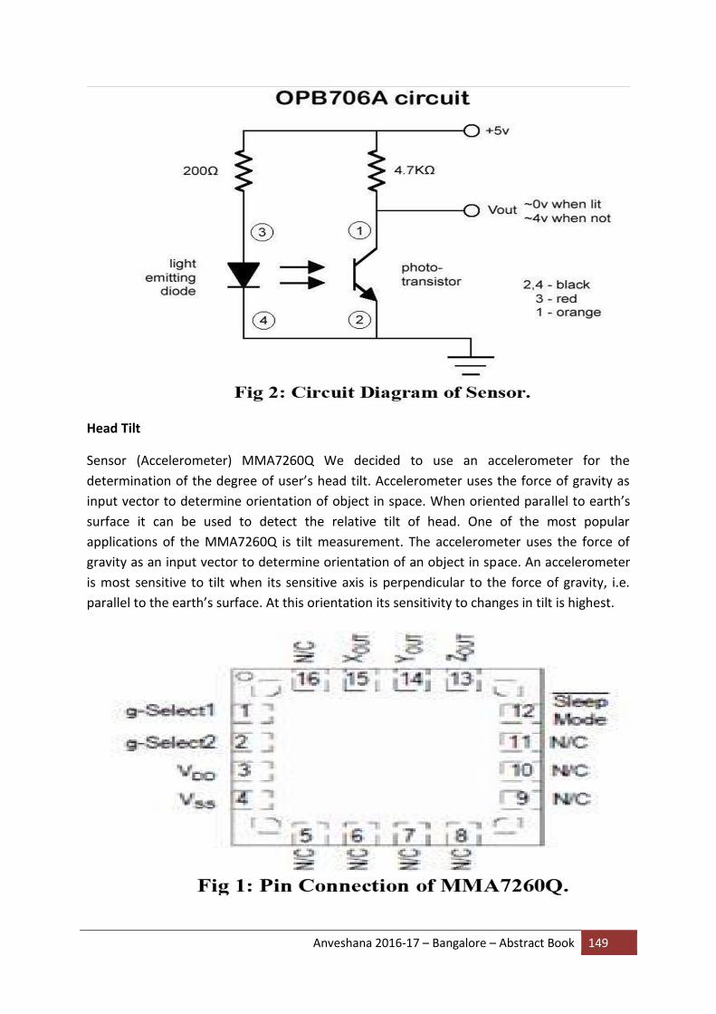
Anveshana 2016-17 – Bangalore – Abstract Book 149
Head Tilt
Sensor (Accelerometer) MMA7260Q We decided to use an accelerometer for the
determination of the degree of user’s head tilt. Accelerometer uses the force of gravity as
input vector to determine orientation of object in space. When oriented parallel to earth’s
surface it can be used to detect the relative tilt of head. One of the most popular
applications of the MMA7260Q is tilt measurement. The accelerometer uses the force of
gravity as an input vector to determine orientation of an object in space. An accelerometer
is most sensitive to tilt when its sensitive axis is perpendicular to the force of gravity, i.e.
parallel to the earth’s surface. At this orientation its sensitivity to changes in tilt is highest.

Anveshana 2016-17 – Bangalore – Abstract Book 150
The accelerometer consist of a g-cell which does the work of sensing change in acceleration
and hence the tilt. G-cell consists of two capacitive sensing cells, formed using 3 beams,
where the middle beam is is movable. Thus, these are 2 back-back capacitors.
Now, we know that capacitance is given as: C=Ɛ A/d Where, A is the area of the beam. Ɛ is
the dielectric constant. D is the distance between the beams. So, whenever there is a tilt in
the either X or Y axis, the middle beam moves changing its distance with respect to the
other two fixed plate. This changes the resultant capacitance of the G-cell. This change in
capacitance is used to determine the output of the accelerometer. The IC also signal
conditions and filters the output signal, providing a high level output voltage that is
ratiometric and proportional to acceleration.
A/D converter the output of the sensor is fed into the A/D converter for the conversion of
analog signal which is the output of the sensor to digital signal which is fed to the
microcontroller for further processing of data. The reason why we are using A/D converter is

Anveshana 2016-17 – Bangalore – Abstract Book 151
that microcontroller works on the digital signal for the further processing of data. Here we
are using HD74LS90P to provide necessary clock pulse to the ADC.
Micro- controller
The output of IR transceiver and accelerometer are detected by micro-controller after
getting processed through A/D convertor. The function of the micro-controller is to receive
the data from A/D converter, process it and then send suitable signals to the computer’s
serial port. The AT89S52 is a low power, high-performance CMOS 8-Bit microcontroller with
8k bytes of in-system programmable Flash memory. The device is manufactured using
Atmel’s high-density non-volatile memory technology and is compatible with the industry-
standard 80C51 instruction set and pin out. The onchip Flash allows the program memory to
be reprogrammed in-system or by a conventional non- volatile memory programmer. By
combing a versatile 8-bit CPU with in system programmable Flash on a monolithic chip, the
Atmel AT89S52 is a powerful microcontroller which provides a highly-flexible and cost-
effective solution to many embedded control applications. RS-232 Interface (MAX 232) RS-
232 is a serial communication cable which is needed for communication between the
computer and the microcontroller. The RS-232 communication is preferred because; 1. It
requires only 2 lines and a common ground. 2. Serial communication is easy to implement.
The micro-controller circuitry works with TTL logic +5V as logic 1 and 0v as logic 0. However
RS-232 standard have different voltage levels. They are 3-15V for TTL logics 0 and -3 to -15 V
for TTL logic 1.Hence conversion of TTL levels to these levels are required. This is done by
MAX 232 IC with the help of the 1µf capacitor connected to it. The output of MAX232 is
given to the RS-232 connector. It is then given to the PC through the DB-9 connector.

Anveshana 2016-17 – Bangalore – Abstract Book 152
Power supply
A fixed voltage power supply producing constant +5V consists of step down transformer, a
bridge rectifier, filter capacitors C1 and 3 terminal regulator IC LM7805. A step down
transformer is selected in such a way that it produces 9V at the input of IC. This power
supply is capable of supplying +5v and load current up to 500m A. The capacitor C2
connected between output terminal and ground cancels out any inductive effect due to long
distribution leads. Input capacitor C1 is used to improve transient response of the regulator
IC, i.e. response of regulator to sudden changes in load. It is also helpful in reducing the
noise present in the output. Dropout voltage (Vin-Vout) needs to be at least 2V under all
operating conditions for proper operation of regulator.

Anveshana 2016-17 – Bangalore – Abstract Book 153
2.2 Software Description
We are use two software’s for the working of our projects. One code is placed in
microcontroller for transmission of information regarding and click. Another program runs
on PC to collect the data from serial port and set mouse cursor accordingly. We use the
followings software’s: 1) Keil C software- To write program for 8052. 2) Visual basic 6.0-To
receive data at PC. 3) Hyperlink terminal-To show input on PC. During the program, we first
check the clicking condition that is, whether the output from IR receiver is more than 40 mV
as compared to its initial value.

Anveshana 2016-17 – Bangalore – Abstract Book 154