in this chapter - automationdirect (div) 5–74 divide binary (divb) 5–81 divide double (divd)...
TRANSCRIPT
Standard rLL and InteLLIgent Box InStructIonS 555
ChapterChapterChapter
In This Chapter...Introduction ............................................................................................................... 5-2
Using Boolean Instructions ....................................................................................... 5-4
Boolean Instructions .................................................................................................. 5-9
Comparative Boolean .............................................................................................. 5-25
Immediate Instructions ........................................................................................... 5-31
Timer, Counter and Shift Register Instructions ...................................................... 5-35
Accumulator/Stack Load and Output Data Instructions ........................................ 5-48
Logical Instructions (Accumulator) ......................................................................... 5-60
Math Instructions .................................................................................................... 5-68
Bit Operation Instructions ....................................................................................... 5-82
Number Conversion Instructions (Accumulator) .................................................... 5-87
Table Instructions .................................................................................................... 5-96
CPU Control Instructions ......................................................................................... 5-99
Program Control Instructions ............................................................................... 5-101
Interrupt Instructions ............................................................................................ 5-108
Message Instructions ............................................................................................. 5-111
Intelligent I/O Instructions .................................................................................... 5-118
Network Instructions ............................................................................................. 5-120
Intelligent Box (IBox) Instructions ........................................................................ 5-124
DL05 Micro PLC User Manual, 6th Edition, Rev. E5-2
Chapter 5: Standard RLL Instructions
IntroductionDL05 Micro PLCs offer a wide variety of instructions to perform many different types of operations. This chapter shows you how to use each standard Relay Ladder Logic (RLL) instruction. In addition to these instructions, you may also need to refer to the Drum instruction in Chapter 6, or the Stage programming instructions in Chapter 7.
There are two ways to quickly find the instruction you need.
• If you know the instruction category (Boolean, Comparative Boolean, etc.) just use the title at the top of the page to find the pages that discuss the instructions in that category.
• If you know the individual instruction name, use the following table to find the page(s) that discusses the instruction.
Accumulating Timer (TMRA) 5–38
Accumulating Fast Timer (TMRAF) 5-38
Add (ADD) 5–68
Add Binary (ADDB) 5–78
Add Double (ADDD) 5–69
And (AND) 5–13
And (AND) 5–30
And (AND) 5–60
And Bit-of-Word (ANDB) 5-14
And Double (ANDD) 5–61
And If Equal (ANDE) 5–27
And If Not Equal (ANDNE) 5–27
And Immediate (ANDI) 5–32
And Negative Differential (ANDND) 5–21
And Not (ANDN) 5–13
And Not (ANDN) 5–30
And Not Bit-of-Word (ANDNB) 5-14
And Not Immediate (ANDNI) 5–32
And Positive Differential (ANDPD) 5–21
And Store (AND STR) 5–15
ASCII Constant (ACON) 5–112
ASCII to HEX (ATH) 5–90
Binary (BIN) 5–87
Binary Coded Decimal (BCD) 5–88
Compare (CMP) 5–66
Compare Double (CMPD) 5–67
Counter (CNT) 5–41
Data Label (DLBL) 5–112
Decode (DECO) 5–86
Decrement (DEC) 5–76
Decrement Binary (DECB) 5–77
Disable Interrupts (DISI) 5–109
Divide (DIV) 5–74
Divide Binary (DIVB) 5–81
Divide Double (DIVD) 5–75
Enable Interrupts (ENI) 5–108
Encode (ENCO) 5–85
End (END) 5–99
Exclusive Or (XOR) 5–64
Exclusive Or Double (XORD) 5–65
Fault (FAULT) 5–111
For / Next (FOR) (NEXT) 5–101
Goto Subroutine (GTS) (SBR) 5–103
Gray Code (GRAY) 5–93
HEX to ASCII (HTA) 5–91
Increment (INC) 5–76
Increment Binary (INCB) 5–77
Interrupt (INT) 5–108
Interrupt Return (IRT) 5–108
Interrupt Return Conditional (IRTC) 5–108
Invert (INV) 5–89
Load (LD) 5–53
Load Address (LDA) 5–56
Load Double (LDD) 5–54
Load Formatted (LDF) 5–55
Load Label (LDLBL) 5–97
Instruction Page Instruction Page
DL05 Micro PLC User Manual, 6th Edition, Rev. E 5-3
Chapter 5: Standard RLL Instructions
Master Line Reset (MLR) 5–106
Master Line Set (MLS) 5–106
Move (MOV) 5–96
Move Memory Cartridge (MOVMC) 5–97
Multiply (MUL) 5–72
Multiply Binary (MULB) 5–80
Multiply Double (MULD) 5–73
No Operation (NOP) 5–99
Not (NOT) 5–18
Numerical Constant (NCON) 5–112
Or (OR) 5–11
Or (OR) 5–29
Or (OR) 5–62
Or Bit-of-Word (ORB) 5-12
Or Double (ORD) 5–63
Or If Equal (ORE) 5–26
Or If Not Equal (ORNE) 5–26
Or Immediate (ORI) 5–31
Or Negative Differential (ORND) 5–20
Or Not (ORN) 5–11
Or Not (ORN) 5–29
Or Not Bit-of-Word (ORNB) 5-12
Or Not Immediate (ORNI) 5–31
Or Out (OR OUT) 5–16
Or Out Immediate (OROUTI) 5–33
Or Positive Differential (ORPD) 5–20
Or Store (OR STR) 5–15
Out (OUT) 5–16
Out (OUT) 5–57
Out Bit-of-Word (OUTB) 5-17
Out Double (OUTD) 5–57
Out Formatted (OUTF) 5–58
Out Immediate (OUTI) 5–33
Pause (PAUSE) 5–24
Pop (POP) 5–58
Positive Differential (PD) 5–18
Print Message (PRINT) 5–114
Read from Intelligent Box I/O Module (RD) 5-118
Read from Network (RX) 5–120
Reset (RST) 5–22
Reset Bit-of-Word (RSTB) 5-23
Reset Immediate (RSTI) 5–34
Reset Watch Dog Timer (RSTWT) 5–100
Set (SET) 5–22
Set Bit-of-Word (SETB) 5-23
Set Immediate (SETI) 5–34
Shift Left (SHFL) 5–83
Shift Register (SR) 5–47
Shift Right (SHFR) 5–84
Shuffle Digits (SFLDGT) 5–94
Stage Counter (SGCNT) 5–43
Stop (STOP) 5–99
Store (STR) 5–9
Store (STR) 5-28
Store Bit-of-Word (STRB) 5-10
Store If Equal (STRE) 5–25
Store If Not Equal (STRNE) 5–25
Store Immediate (STRI) 5–31
Store Negative Differential (STRND) 5–19
Store Not (STRN) 5–9
Store Not (STRN) 5-28
Store Not Bit-of-Word (STRNB) 5-10
Store Not Immediate (STRNI) 5–31
Store Positive Differential (STRPD) 5–19
Subroutine Return (RT) 5–103
Subroutine Return Conditional (RTC) 5–103
Subtract (SUB) 5–70
Subtract Binary (SUBB) 5–79
Subtract Double (SUBD) 5–71
Sum (SUM) 5–81
Timer (TMR) and Timer Fast (TMRF) 5–36
Up Down Counter (UDC) 5–45
Write to Intelligent Box I/O Module (WT) 5-119
Write to Network (WX) 5–122
Instruction Page Instruction Page
DL05 Micro PLC User Manual, 6th Edition, Rev. E5-4
Chapter 5: Standard RLL Instructions
Using Boolean InstructionsDo you ever wonder why so many PLC manufacturers always quote the scan time for a 1K Boolean program? Simple. Most all programs utilize many Boolean instructions. These are typically very simple instructions designed to join input and output contacts in various series and parallel combinations. Our DirectSOFT software is a similar program. It uses graphic symbols to develop a program; therefore, you don’t necessarily have to know the instruction mnemonics in order to develop your program. However, knowledge of mnemonics will be helpful, whenever it becomes necessary to troubleshoot a program using a handheld programmer (HPP).
Many of the instructions in this chapter are not program instructions used in DirectSOFT, but are implied. In other words, they are not actually keyboard commands, however, they can be seen in a Mnemonic View of the program once the DirectSOFT program has been developed and accepted (compiled). Each instruction listed in this chapter will have a small chart to indicate how the instruction is used with DirectSOFT and the HPP.
The following paragraphs show how these instructions are used to build simple ladder programs.
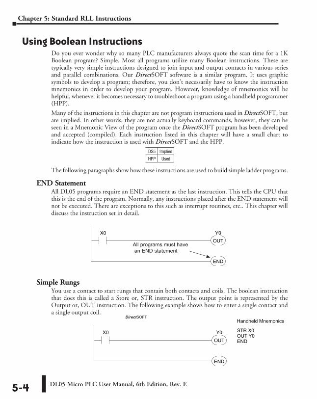
END StatementAll DL05 programs require an END statement as the last instruction. This tells the CPU that this is the end of the program. Normally, any instructions placed after the END statement will not be executed. There are exceptions to this such as interrupt routines, etc.. This chapter will discuss the instruction set in detail.
Simple RungsYou use a contact to start rungs that contain both contacts and coils. The boolean instruction that does this is called a Store or, STR instruction. The output point is represented by the Output or, OUT instruction. The following example shows how to enter a single contact and a single output coil.
OUTY0X0
END
All programs must have an END statement
DS5 Implied
HPP Used
OUTY0X0
END
DirectSOFT Example Handheld Mnemonics
STR X0OUT Y0END
DirectSOFT
DL05 Micro PLC User Manual, 6th Edition, Rev. E 5-5
Chapter 5: Standard RLL Instructions
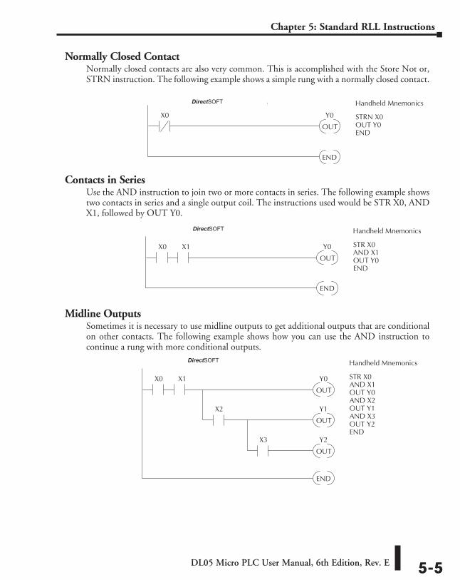
Normally Closed ContactNormally closed contacts are also very common. This is accomplished with the Store Not or, STRN instruction. The following example shows a simple rung with a normally closed contact.
Contacts in SeriesUse the AND instruction to join two or more contacts in series. The following example shows two contacts in series and a single output coil. The instructions used would be STR X0, AND X1, followed by OUT Y0.
Midline OutputsSometimes it is necessary to use midline outputs to get additional outputs that are conditional on other contacts. The following example shows how you can use the AND instruction to continue a rung with more conditional outputs.
OUT
Y0X0
END
X1
Direct SOFT32 Example Handheld Mnemonics
STR X0AND X1OUT Y0AND X2OUT Y1AND X3OUT Y2END
X2
OUT
Y1
X3
OUT
Y2
OUT
Y0X0
END
X1
Direct SOFT32 Example Handheld Mnemonics
STR X0AND X1OUT Y0END
OUT
Y0X0
END
Direct SOFT32 Example Handheld Mnemonics
STRN X0OUT Y0END
DirectSOFT
DirectSOFT
DirectSOFT
DL05 Micro PLC User Manual, 6th Edition, Rev. E5-6
Chapter 5: Standard RLL Instructions
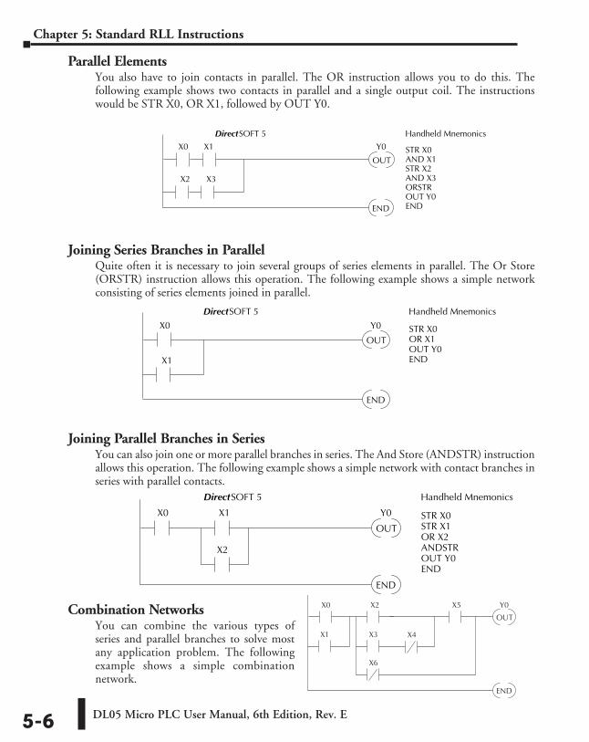
Parallel ElementsYou also have to join contacts in parallel. The OR instruction allows you to do this. The following example shows two contacts in parallel and a single output coil. The instructions would be STR X0, OR X1, followed by OUT Y0.
Joining Series Branches in ParallelQuite often it is necessary to join several groups of series elements in parallel. The Or Store (ORSTR) instruction allows this operation. The following example shows a simple network consisting of series elements joined in parallel.
Joining Parallel Branches in SeriesYou can also join one or more parallel branches in series. The And Store (ANDSTR) instruction allows this operation. The following example shows a simple network with contact branches in series with parallel contacts.
Combination NetworksYou can combine the various types of series and parallel branches to solve most any application problem. The following example shows a simple combination network.
OUT
Y0X0
END
X2
X3X1 X4
X5
X6
OUT
Y0X0
END
X1
X2
DirectSOFT 5 Handheld Mnemonics
STR X0STR X1OR X2ANDSTROUT Y0END
OUT
Y0X0
END
X2
X1
X3
DirectSOFT 5 Handheld Mnemonics
STR X0AND X1STR X2AND X3ORSTROUT Y0END
OUT
Y0X0
END
X1
DirectSOFT 5 Handheld Mnemonics
STR X0OR X1OUT Y0END
DL05 Micro PLC User Manual, 6th Edition, Rev. E 5-7
Chapter 5: Standard RLL Instructions
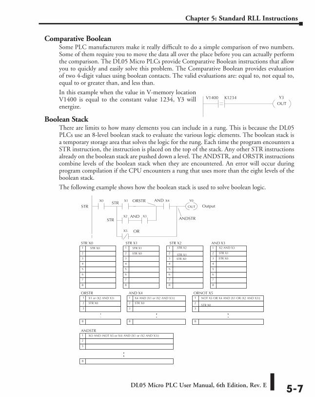
Comparative BooleanSome PLC manufacturers make it really difficult to do a simple comparison of two numbers. Some of them require you to move the data all over the place before you can actually perform the comparison. The DL05 Micro PLCs provide Comparative Boolean instructions that allow you to quickly and easily solve this problem. The Comparative Boolean provides evaluation of two 4-digit values using boolean contacts. The valid evaluations are: equal to, not equal to, equal to or greater than, and less than.
In this example when the value in V-memory location V1400 is equal to the constant value 1234, Y3 will energize.
Boolean StackThere are limits to how many elements you can include in a rung. This is because the DL05 PLCs use an 8-level boolean stack to evaluate the various logic elements. The boolean stack is a temporary storage area that solves the logic for the rung. Each time the program encounters a STR instruction, the instruction is placed on the top of the stack. Any other STR instructions already on the boolean stack are pushed down a level. The ANDSTR, and ORSTR instructions combine levels of the boolean stack when they are encountered. An error will occur during program compilation if the CPU encounters a rung that uses more than the eight levels of the boolean stack.
The following example shows how the boolean stack is used to solve boolean logic.
Y3OUT
V1400 K1234
X1 or (X2 AND X3)
STR X0 STR X1 STR X21 STR X0
2
3
4
5
6
7
8
1 STR X1
2 STR X0
3
4
5
6
7
8
1 STR X2 STR X1 2
3 STR X0
4
5
6
7
8
AND X31 X2 AND X3
2 STR X1
3 STR X0
4
5
6
7
8
ORSTR 1
2 STR X0
3
8
OUT
Y0X0 X1
X2 X3
X4
X5
STR
OR
AND
ORSTR
ANDSTR
OutputSTR
STR
AND
X4 AND {X1 or (X2 AND X3)}
AND X41
2 STR X0
3
8
NOT X5 OR X4 AND {X1 OR (X2 AND X3)} STR X0
ORNOT X51
2 3
8
ANDSTR XO AND (NOT X5 or X4) AND {X1 or (X2 AND X3)}
1
2
3
8
.
. . .
. .
.
.
DL05 Micro PLC User Manual, 6th Edition, Rev. E5-8
Chapter 5: Standard RLL Instructions
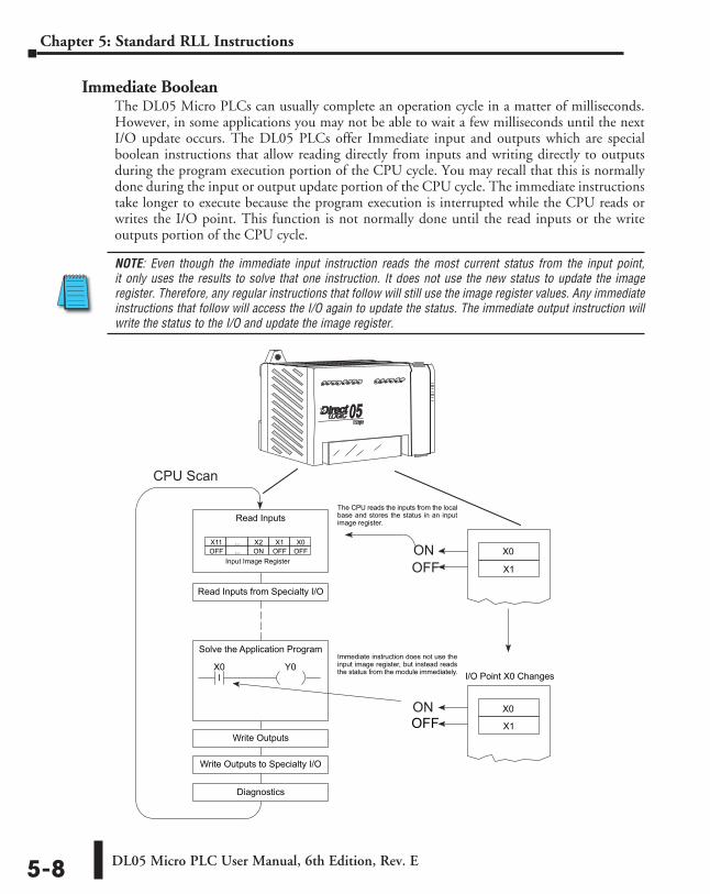
Immediate BooleanThe DL05 Micro PLCs can usually complete an operation cycle in a matter of milliseconds. However, in some applications you may not be able to wait a few milliseconds until the next I/O update occurs. The DL05 PLCs offer Immediate input and outputs which are special boolean instructions that allow reading directly from inputs and writing directly to outputs during the program execution portion of the CPU cycle. You may recall that this is normally done during the input or output update portion of the CPU cycle. The immediate instructions take longer to execute because the program execution is interrupted while the CPU reads or writes the I/O point. This function is not normally done until the read inputs or the write outputs portion of the CPU cycle.
NOTE: Even though the immediate input instruction reads the most current status from the input point, it only uses the results to solve that one instruction. It does not use the new status to update the image register. Therefore, any regular instructions that follow will still use the image register values. Any immediate instructions that follow will access the I/O again to update the status. The immediate output instruction will write the status to the I/O and update the image register.
X1
Read Inputs
Diagnostics
Input Image Register
The CPU reads the inputs from the localbase and stores the status in an inputimage register.
X0 Y0
X0X1X2...X11OFFOFFON...OFF
Solve the Application Program
Read Inputs from Specialty I/O
Write Outputs
Write Outputs to Specialty I/O
X0
X1OFF
Immediate instruction does not use theinput image register, but instead readsthe status from the module immediately. I/O Point X0 Changes
ON
ONOFF
CPU Scan
I
X0
DL05 Micro PLC User Manual, 6th Edition, Rev. E 5-9
Chapter 5: Standard RLL Instructions
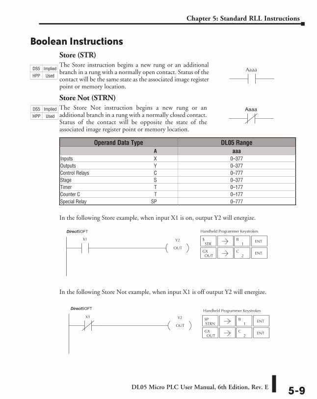
Boolean InstructionsStore (STR)The Store instruction begins a new rung or an additional branch in a rung with a normally open contact. Status of the contact will be the same state as the associated image register point or memory location.
Store Not (STRN)The Store Not instruction begins a new rung or an additional branch in a rung with a normally closed contact. Status of the contact will be opposite the state of the associated image register point or memory location.
In the following Store example, when input X1 is on, output Y2 will energize.
In the following Store Not example, when input X1 is off output Y2 will energize.
Aaaa
Aaaa
Operand Data Type DL05 Range ⸠⸠⸠⸠⸠⸠⸠⸠⸠⸠⸠⸠⸠⸠⸠⸠⸠⸠⸠⸠⸠⸠⸠⸠⸠⸠⸠⸠⸠⸠⸠⸠⸠⸠⸠⸠⸠⸠⸠⸠⸠⸠⸠⸠⸠⸠⸠⸠⸠⸠⸠⸠⸠⸠⸠⸠⸠⸠⸠⸠⸠⸠⸠⸠⸠⸠⸠⸠⸠⸠⸠⸠⸠A aaaInputs ⸠⸠⸠⸠⸠⸠⸠⸠⸠⸠⸠⸠⸠⸠⸠⸠⸠⸠⸠⸠⸠⸠⸠⸠⸠⸠⸠⸠⸠⸠⸠⸠⸠⸠⸠⸠⸠⸠⸠⸠⸠⸠⸠⸠⸠⸠⸠⸠⸠⸠⸠⸠⸠⸠⸠⸠⸠⸠⸠⸠⸠⸠⸠⸠⸠⸠X 0–377Outputs ⸠⸠⸠⸠⸠⸠⸠⸠⸠⸠⸠⸠⸠⸠⸠⸠⸠⸠⸠⸠⸠⸠⸠⸠⸠⸠⸠⸠⸠⸠⸠⸠⸠⸠⸠⸠⸠⸠⸠⸠⸠⸠⸠⸠⸠⸠⸠⸠⸠⸠⸠⸠⸠⸠⸠⸠⸠⸠⸠⸠⸠⸠⸠⸠Y 0–377Control Relays ⸠⸠⸠⸠⸠⸠⸠⸠⸠⸠⸠⸠⸠⸠⸠⸠⸠⸠⸠⸠⸠⸠⸠⸠⸠⸠⸠⸠⸠⸠⸠⸠⸠⸠⸠⸠⸠⸠⸠⸠⸠⸠⸠⸠⸠⸠⸠⸠⸠⸠⸠⸠C 0–777Stage ⸠⸠⸠⸠⸠⸠⸠⸠⸠⸠⸠⸠⸠⸠⸠⸠⸠⸠⸠⸠⸠⸠⸠⸠⸠⸠⸠⸠⸠⸠⸠⸠⸠⸠⸠⸠⸠⸠⸠⸠⸠⸠⸠⸠⸠⸠⸠⸠⸠⸠⸠⸠⸠⸠⸠⸠⸠⸠⸠⸠⸠⸠⸠⸠⸠⸠S 0–377Timer ⸠⸠⸠⸠⸠⸠⸠⸠⸠⸠⸠⸠⸠⸠⸠⸠⸠⸠⸠⸠⸠⸠⸠⸠⸠⸠⸠⸠⸠⸠⸠⸠⸠⸠⸠⸠⸠⸠⸠⸠⸠⸠⸠⸠⸠⸠⸠⸠⸠⸠⸠⸠⸠⸠⸠⸠⸠⸠⸠⸠⸠⸠⸠⸠⸠⸠ T 0–177Counter C ⸠⸠⸠⸠⸠⸠⸠⸠⸠⸠⸠⸠⸠⸠⸠⸠⸠⸠⸠⸠⸠⸠⸠⸠⸠⸠⸠⸠⸠⸠⸠⸠⸠⸠⸠⸠⸠⸠⸠⸠⸠⸠⸠⸠⸠⸠⸠⸠⸠⸠⸠⸠⸠⸠⸠⸠⸠⸠⸠⸠ T 0–177Special Relay ⸠⸠⸠⸠⸠⸠⸠⸠⸠⸠⸠⸠⸠⸠⸠⸠⸠⸠⸠⸠⸠⸠⸠⸠⸠⸠⸠⸠⸠⸠⸠⸠⸠⸠⸠⸠⸠⸠⸠⸠⸠⸠⸠⸠⸠⸠⸠⸠⸠⸠⸠⸠⸠SP 0–777
STR$
1B ENT
OUTGX
2C ENT
Handheld Programmer KeystrokesDirect SOFT32
Y2
OUT
X1
STRNSP
1B ENT
OUTGX
2C ENT
Y2
OUT
X1
Handheld Programmer KeystrokesDirect SOFT32
DS5 Implied
HPP Used
DS5 Implied
HPP Used
DirectSOFT
DirectSOFT

DL05 Micro PLC User Manual, 6th Edition, Rev. E5-10
Chapter 5: Standard RLL Instructions
Store Bit-of-Word (STRB)The Store Bit-of-Word instruction begins a new rung or an additional branch in a rung with a normally open contact. Status of the contact will be the same state as the bit referenced in the associated memory location.
Store Not Bit-of-Word (STRNB)The Store Not Bit-of-Word instruction begins a new rung or an additional branch in a rung with a normally closed contact. Status of the contact will be opposite the state of the bit referenced in the associated memory location.
In the following Store Bit-of-Word example, when bit 12 of V-memory location V1400 is on, output Y2 will energize.
In the following Store Not Bit-of-Word example, when bit 12 of V-memory location V1400 is off, output Y2 will energize.
Aaaa.bb
Aaaa.bb
Operand Data Type DL05 Range ⸠⸠⸠⸠⸠⸠⸠⸠⸠⸠⸠⸠⸠⸠⸠⸠⸠⸠⸠⸠⸠⸠⸠⸠⸠⸠⸠⸠⸠⸠⸠⸠⸠⸠⸠⸠⸠⸠⸠⸠⸠⸠⸠⸠⸠⸠⸠⸠⸠⸠⸠⸠⸠⸠⸠⸠⸠⸠⸠⸠⸠⸠⸠⸠⸠⸠⸠⸠⸠⸠⸠⸠⸠⸠⸠ A aaa bbV-memory ⸠⸠⸠⸠⸠⸠⸠⸠⸠⸠⸠⸠⸠⸠⸠⸠⸠⸠⸠⸠⸠⸠⸠⸠⸠⸠⸠⸠⸠⸠⸠⸠⸠⸠⸠⸠⸠⸠⸠⸠⸠⸠⸠⸠⸠⸠⸠⸠⸠⸠⸠⸠⸠⸠⸠⸠⸠⸠⸠⸠ B See memory map BCD, 0 to 15
Pointer ⸠⸠⸠⸠⸠⸠⸠⸠⸠⸠⸠⸠⸠⸠⸠⸠⸠⸠⸠⸠⸠⸠⸠⸠⸠⸠⸠⸠⸠⸠⸠⸠⸠⸠⸠⸠⸠⸠⸠⸠⸠⸠⸠⸠⸠⸠⸠⸠⸠⸠⸠⸠⸠⸠⸠⸠⸠⸠⸠⸠⸠⸠⸠⸠⸠⸠ PB See memory map BCD, 0 to 15
Handheld Programmer Keystrokes
DirectSOFT32
Y2
OUT
B1400.12
STR V 1
OUT 2
SHFT 4 0 0
1 2 ENT
ENT
K
B
Y2
OUT
B1400.12
DirectSOFT32
OUT 2 ENT
Handheld Programmer Keystrokes
STRN V 1SHFT 4 0 0
1 2 ENTK
B
DS5 Implied
HPP Used
DS5 Implied
HPP Used
DirectSOFT
DirectSOFT
DL05 Micro PLC User Manual, 6th Edition, Rev. E 5-11
Chapter 5: Standard RLL Instructions
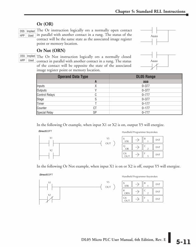
Or (OR)The Or instruction logically ors a normally open contact in parallel with another contact in a rung. The status of the contact will be the same state as the associated image register point or memory location.
Or Not (ORN)The Or Not instruction logically ors a normally closed contact in parallel with another contact in a rung. The status of the contact will be opposite the state of the associated image register point or memory location.
In the following Or example, when input X1 or X2 is on, output Y5 will energize.
In the following Or Not example, when input X1 is on or X2 is off, output Y5 will energize.
Aaaa
Aaaa
Operand Data Type DL05 Range ⸠⸠⸠⸠⸠⸠⸠⸠⸠⸠⸠⸠⸠⸠⸠⸠⸠⸠⸠⸠⸠⸠⸠⸠⸠⸠⸠⸠⸠⸠⸠⸠⸠⸠⸠⸠⸠⸠⸠⸠⸠⸠⸠⸠⸠⸠⸠⸠⸠⸠⸠⸠⸠⸠⸠⸠⸠⸠⸠⸠⸠⸠⸠⸠⸠⸠⸠⸠⸠⸠⸠⸠⸠A aaaInputs ⸠⸠⸠⸠⸠⸠⸠⸠⸠⸠⸠⸠⸠⸠⸠⸠⸠⸠⸠⸠⸠⸠⸠⸠⸠⸠⸠⸠⸠⸠⸠⸠⸠⸠⸠⸠⸠⸠⸠⸠⸠⸠⸠⸠⸠⸠⸠⸠⸠⸠⸠⸠⸠⸠⸠⸠⸠⸠⸠⸠⸠⸠⸠⸠⸠X 0–377Outputs ⸠⸠⸠⸠⸠⸠⸠⸠⸠⸠⸠⸠⸠⸠⸠⸠⸠⸠⸠⸠⸠⸠⸠⸠⸠⸠⸠⸠⸠⸠⸠⸠⸠⸠⸠⸠⸠⸠⸠⸠⸠⸠⸠⸠⸠⸠⸠⸠⸠⸠⸠⸠⸠⸠⸠⸠⸠⸠⸠⸠⸠⸠⸠Y 0–377Control Relays ⸠⸠⸠⸠⸠⸠⸠⸠⸠⸠⸠⸠⸠⸠⸠⸠⸠⸠⸠⸠⸠⸠⸠⸠⸠⸠⸠⸠⸠⸠⸠⸠⸠⸠⸠⸠⸠⸠⸠⸠⸠⸠⸠⸠⸠⸠⸠⸠⸠⸠⸠⸠C 0–777Stage ⸠⸠⸠⸠⸠⸠⸠⸠⸠⸠⸠⸠⸠⸠⸠⸠⸠⸠⸠⸠⸠⸠⸠⸠⸠⸠⸠⸠⸠⸠⸠⸠⸠⸠⸠⸠⸠⸠⸠⸠⸠⸠⸠⸠⸠⸠⸠⸠⸠⸠⸠⸠⸠⸠⸠⸠⸠⸠⸠⸠⸠⸠⸠⸠⸠⸠S 0–377Timer ⸠⸠⸠⸠⸠⸠⸠⸠⸠⸠⸠⸠⸠⸠⸠⸠⸠⸠⸠⸠⸠⸠⸠⸠⸠⸠⸠⸠⸠⸠⸠⸠⸠⸠⸠⸠⸠⸠⸠⸠⸠⸠⸠⸠⸠⸠⸠⸠⸠⸠⸠⸠⸠⸠⸠⸠⸠⸠⸠⸠⸠⸠⸠⸠⸠⸠ T 0–177Counter ⸠⸠⸠⸠⸠⸠⸠⸠⸠⸠⸠⸠⸠⸠⸠⸠⸠⸠⸠⸠⸠⸠⸠⸠⸠⸠⸠⸠⸠⸠⸠⸠⸠⸠⸠⸠⸠⸠⸠⸠⸠⸠⸠⸠⸠⸠⸠⸠⸠⸠⸠⸠⸠⸠⸠⸠⸠⸠⸠⸠⸠CT 0–177Special Relay ⸠⸠⸠⸠⸠⸠⸠⸠⸠⸠⸠⸠⸠⸠⸠⸠⸠⸠⸠⸠⸠⸠⸠⸠⸠⸠⸠⸠⸠⸠⸠⸠⸠⸠⸠⸠⸠⸠⸠⸠⸠⸠⸠⸠⸠⸠⸠⸠⸠⸠⸠⸠SP 0–777
STR$
1B ENT
ORQ
2C ENT
OUTGX
5F ENT
Y5
OUT
X1
X2
Handheld Programmer KeystrokesDirect SOFT32
STR$
1B ENT
2C ENT
OUTGX
5F ENT
ORNR
X1 Y5
OUT
X2
Handheld Programmer KeystrokesDirect SOFT32
DS5 Implied
HPP Used
DS5 Implied
HPP Used
DirectSOFT
DirectSOFT
DL05 Micro PLC User Manual, 6th Edition, Rev. E5-12
Chapter 5: Standard RLL Instructions
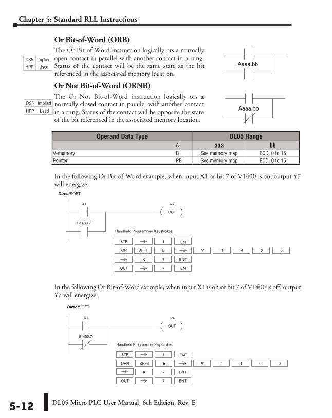
Or Bit-of-Word (ORB)The Or Bit-of-Word instruction logically ors a normally open contact in parallel with another contact in a rung. Status of the contact will be the same state as the bit referenced in the associated memory location.
Or Not Bit-of-Word (ORNB)The Or Not Bit-of-Word instruction logically ors a normally closed contact in parallel with another contact in a rung. Status of the contact will be opposite the state of the bit referenced in the associated memory location.
In the following Or Bit-of-Word example, when input X1 or bit 7 of V1400 is on, output Y7 will energize.
In the following Or Bit-of-Word example, when input X1 is on or bit 7 of V1400 is off, output Y7 will energize.
Aaaa.bb
Aaaa.bb
Y7
OUT
X1
STR 1
Handheld Programmer Keystrokes
DirectSOFT32
ORN V 1
OUT 7
4 0 0
7
B1400.7
ENT
ENT
ENT
K
SHFT B
Operand Data Type DL05 Range ⸠⸠⸠⸠⸠⸠⸠⸠⸠⸠⸠⸠⸠⸠⸠⸠⸠⸠⸠⸠⸠⸠⸠⸠⸠⸠⸠⸠⸠⸠⸠⸠⸠⸠⸠⸠⸠⸠⸠⸠⸠⸠⸠⸠⸠⸠⸠⸠⸠⸠⸠⸠⸠⸠⸠⸠⸠⸠⸠⸠⸠⸠⸠⸠⸠⸠⸠⸠⸠⸠⸠⸠⸠⸠⸠ A aaa bbV-memory ⸠⸠⸠⸠⸠⸠⸠⸠⸠⸠⸠⸠⸠⸠⸠⸠⸠⸠⸠⸠⸠⸠⸠⸠⸠⸠⸠⸠⸠⸠⸠⸠⸠⸠⸠⸠⸠⸠⸠⸠⸠⸠⸠⸠⸠⸠⸠⸠⸠⸠⸠⸠⸠⸠⸠⸠⸠⸠⸠⸠⸠ B See memory map BCD, 0 to 15Pointer ⸠⸠⸠⸠⸠⸠⸠⸠⸠⸠⸠⸠⸠⸠⸠⸠⸠⸠⸠⸠⸠⸠⸠⸠⸠⸠⸠⸠⸠⸠⸠⸠⸠⸠⸠⸠⸠⸠⸠⸠⸠⸠⸠⸠⸠⸠⸠⸠⸠⸠⸠⸠⸠⸠⸠⸠⸠⸠⸠⸠⸠⸠⸠⸠⸠⸠⸠ PB See memory map BCD, 0 to 15
DS5 Implied
HPP Used
DS5 Implied
HPP Used
DirectSOFT
Y7
OUT
X1
B1400.7
STR 1
Handheld Programmer Keystrokes
DirectSOFT32
OR V 1
OUT 7
SHFT 4 0 0
7
ENT
ENT
ENT
K
B
DirectSOFT
DL05 Micro PLC User Manual, 6th Edition, Rev. E 5-13
Chapter 5: Standard RLL Instructions
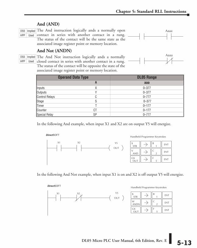
And (AND)The And instruction logically ands a normally open contact in series with another contact in a rung. The status of the contact will be the same state as the associated image register point or memory location.
And Not (ANDN)The And Not instruction logically ands a normally closed contact in series with another contact in a rung. The status of the contact will be opposite the state of the associated image register point or memory location.
In the following And example, when input X1 and X2 are on output Y5 will energize.
In the following And Not example, when input X1 is on and X2 is off output Y5 will energize.
Aaaa
Aaaa
Operand Data Type DL05 Range ⸠⸠⸠⸠⸠⸠⸠⸠⸠⸠⸠⸠⸠⸠⸠⸠⸠⸠⸠⸠⸠⸠⸠⸠⸠⸠⸠⸠⸠⸠⸠⸠⸠⸠⸠⸠⸠⸠⸠⸠⸠⸠⸠⸠⸠⸠⸠⸠⸠⸠⸠⸠⸠⸠⸠⸠⸠⸠⸠⸠⸠⸠⸠⸠⸠⸠⸠⸠⸠⸠⸠⸠⸠A aaaInputs ⸠⸠⸠⸠⸠⸠⸠⸠⸠⸠⸠⸠⸠⸠⸠⸠⸠⸠⸠⸠⸠⸠⸠⸠⸠⸠⸠⸠⸠⸠⸠⸠⸠⸠⸠⸠⸠⸠⸠⸠⸠⸠⸠⸠⸠⸠⸠⸠⸠⸠⸠⸠⸠⸠⸠⸠⸠⸠⸠⸠⸠⸠⸠⸠⸠X 0–377Outputs ⸠⸠⸠⸠⸠⸠⸠⸠⸠⸠⸠⸠⸠⸠⸠⸠⸠⸠⸠⸠⸠⸠⸠⸠⸠⸠⸠⸠⸠⸠⸠⸠⸠⸠⸠⸠⸠⸠⸠⸠⸠⸠⸠⸠⸠⸠⸠⸠⸠⸠⸠⸠⸠⸠⸠⸠⸠⸠⸠⸠⸠⸠⸠Y 0–377Control Relays ⸠⸠⸠⸠⸠⸠⸠⸠⸠⸠⸠⸠⸠⸠⸠⸠⸠⸠⸠⸠⸠⸠⸠⸠⸠⸠⸠⸠⸠⸠⸠⸠⸠⸠⸠⸠⸠⸠⸠⸠⸠⸠⸠⸠⸠⸠⸠⸠⸠⸠⸠⸠C 0–777Stage ⸠⸠⸠⸠⸠⸠⸠⸠⸠⸠⸠⸠⸠⸠⸠⸠⸠⸠⸠⸠⸠⸠⸠⸠⸠⸠⸠⸠⸠⸠⸠⸠⸠⸠⸠⸠⸠⸠⸠⸠⸠⸠⸠⸠⸠⸠⸠⸠⸠⸠⸠⸠⸠⸠⸠⸠⸠⸠⸠⸠⸠⸠⸠⸠⸠⸠S 0–377Timer ⸠⸠⸠⸠⸠⸠⸠⸠⸠⸠⸠⸠⸠⸠⸠⸠⸠⸠⸠⸠⸠⸠⸠⸠⸠⸠⸠⸠⸠⸠⸠⸠⸠⸠⸠⸠⸠⸠⸠⸠⸠⸠⸠⸠⸠⸠⸠⸠⸠⸠⸠⸠⸠⸠⸠⸠⸠⸠⸠⸠⸠⸠⸠⸠⸠⸠ T 0–177Counter ⸠⸠⸠⸠⸠⸠⸠⸠⸠⸠⸠⸠⸠⸠⸠⸠⸠⸠⸠⸠⸠⸠⸠⸠⸠⸠⸠⸠⸠⸠⸠⸠⸠⸠⸠⸠⸠⸠⸠⸠⸠⸠⸠⸠⸠⸠⸠⸠⸠⸠⸠⸠⸠⸠⸠⸠⸠⸠⸠⸠⸠CT 0–177Special Relay ⸠⸠⸠⸠⸠⸠⸠⸠⸠⸠⸠⸠⸠⸠⸠⸠⸠⸠⸠⸠⸠⸠⸠⸠⸠⸠⸠⸠⸠⸠⸠⸠⸠⸠⸠⸠⸠⸠⸠⸠⸠⸠⸠⸠⸠⸠⸠⸠⸠⸠⸠⸠SP 0–777
STR$
1B ENT
2C ENT
OUTGX
5F ENT
ANDV
Y5
OUT
X1 X2
Handheld Programmer KeystrokesDirect SOFT32
ANDNW
STR$
1B ENT
2C ENT
OUTGX
5F ENT
X1 Y5
OUT
X2
Handheld Programmer KeystrokesDirect SOFT32
DS5 Implied
HPP Used
DS5 Implied
HPP Used
DirectSOFT
DirectSOFT
DL05 Micro PLC User Manual, 6th Edition, Rev. E5-14
Chapter 5: Standard RLL Instructions
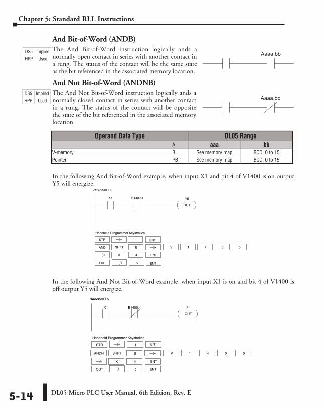
And Bit-of-Word (ANDB)The And Bit-of-Word instruction logically ands a normally open contact in series with another contact in a rung. The status of the contact will be the same state as the bit referenced in the associated memory location.
And Not Bit-of-Word (ANDNB)The And Not Bit-of-Word instruction logically ands a normally closed contact in series with another contact in a rung. The status of the contact will be opposite the state of the bit referenced in the associated memory location.
In the following And Bit-of-Word example, when input X1 and bit 4 of V1400 is on output Y5 will energize.
In the following And Not Bit-of-Word example, when input X1 is on and bit 4 of V1400 is off output Y5 will energize.
Aaaa.bb
Aaaa.bb
Operand Data Type DL05 Range ⸠⸠⸠⸠⸠⸠⸠⸠⸠⸠⸠⸠⸠⸠⸠⸠⸠⸠⸠⸠⸠⸠⸠⸠⸠⸠⸠⸠⸠⸠⸠⸠⸠⸠⸠⸠⸠⸠⸠⸠⸠⸠⸠⸠⸠⸠⸠⸠⸠⸠⸠⸠⸠⸠⸠⸠⸠⸠⸠⸠⸠⸠⸠⸠⸠⸠⸠⸠⸠⸠⸠⸠⸠⸠⸠ A aaa bbV-memory ⸠⸠⸠⸠⸠⸠⸠⸠⸠⸠⸠⸠⸠⸠⸠⸠⸠⸠⸠⸠⸠⸠⸠⸠⸠⸠⸠⸠⸠⸠⸠⸠⸠⸠⸠⸠⸠⸠⸠⸠⸠⸠⸠⸠⸠⸠⸠⸠⸠⸠⸠⸠⸠⸠⸠⸠⸠⸠⸠⸠⸠ B See memory map BCD, 0 to 15Pointer ⸠⸠⸠⸠⸠⸠⸠⸠⸠⸠⸠⸠⸠⸠⸠⸠⸠⸠⸠⸠⸠⸠⸠⸠⸠⸠⸠⸠⸠⸠⸠⸠⸠⸠⸠⸠⸠⸠⸠⸠⸠⸠⸠⸠⸠⸠⸠⸠⸠⸠⸠⸠⸠⸠⸠⸠⸠⸠⸠⸠⸠⸠⸠⸠⸠⸠⸠ PB See memory map BCD, 0 to 15
Y5
OUT
X1 B1400.4
DirectSOFT 5
OUT 5 ENT
Handheld Programmer Keystrokes
V 1SHFT 4 0 0
4 ENTK
B
STR 1 ENT
AND
X1 Y5
OUT
B1400.4
DirectSOFT 5
STR 1
Handheld Programmer Keystrokes
OUT 5
ANDN V 1SHFT 4 0 0
4 ENTK
B
ENT
ENT
DS5 Implied
HPP Used
DS5 Implied
HPP Used
DL05 Micro PLC User Manual, 6th Edition, Rev. E 5-15
Chapter 5: Standard RLL Instructions
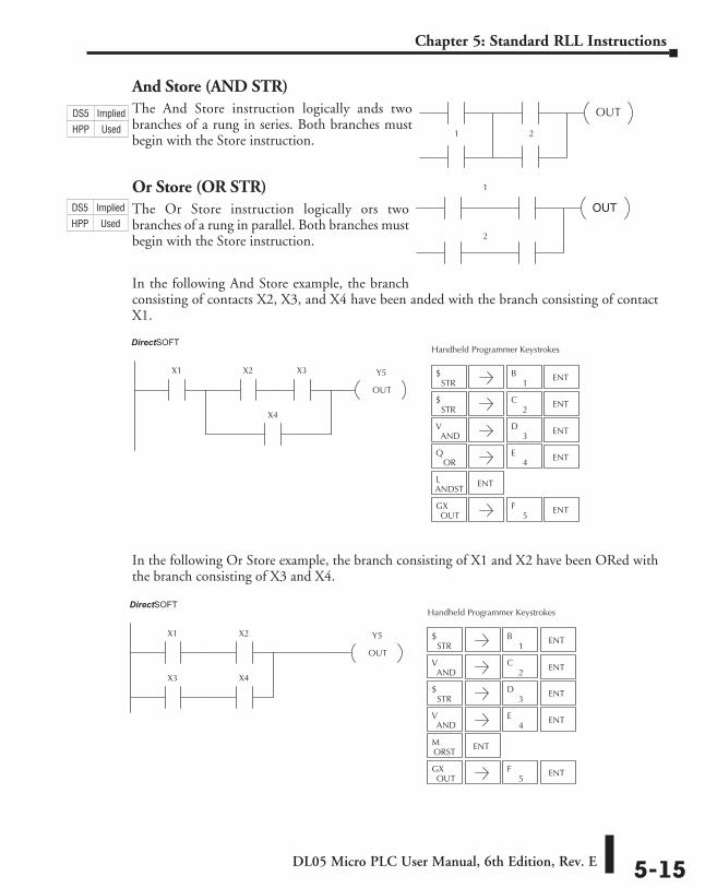
And Store (AND STR)The And Store instruction logically ands two branches of a rung in series. Both branches must begin with the Store instruction.
Or Store (OR STR)The Or Store instruction logically ors two branches of a rung in parallel. Both branches must begin with the Store instruction.
In the following And Store example, the branch consisting of contacts X2, X3, and X4 have been anded with the branch consisting of contact X1.
In the following Or Store example, the branch consisting of X1 and X2 have been ORed with the branch consisting of X3 and X4.
OUT
1 2
OUT
1
2
STR$
1B ENT
STR$ ENT
2C
ANDV ENT
3D
ORQ ENT
4E
ANDSTL ENT
OUTGX
5F ENT
Y5
OUT
X1 X2
X4
X3
Handheld Programmer KeystrokesDirect SOFT32
STR$
1B ENT
STR$ ENT
ANDV ENT
OUTGX
5F ENT
2C
3D
ANDV ENT
4E
ORSTM ENT
Y5
OUT
X1 X2
X3 X4
Handheld Programmer KeystrokesDirect SOFT32
DS5 Implied
HPP Used
DS5 Implied
HPP Used
DirectSOFT
DirectSOFT
DL05 Micro PLC User Manual, 6th Edition, Rev. E5-16
Chapter 5: Standard RLL Instructions
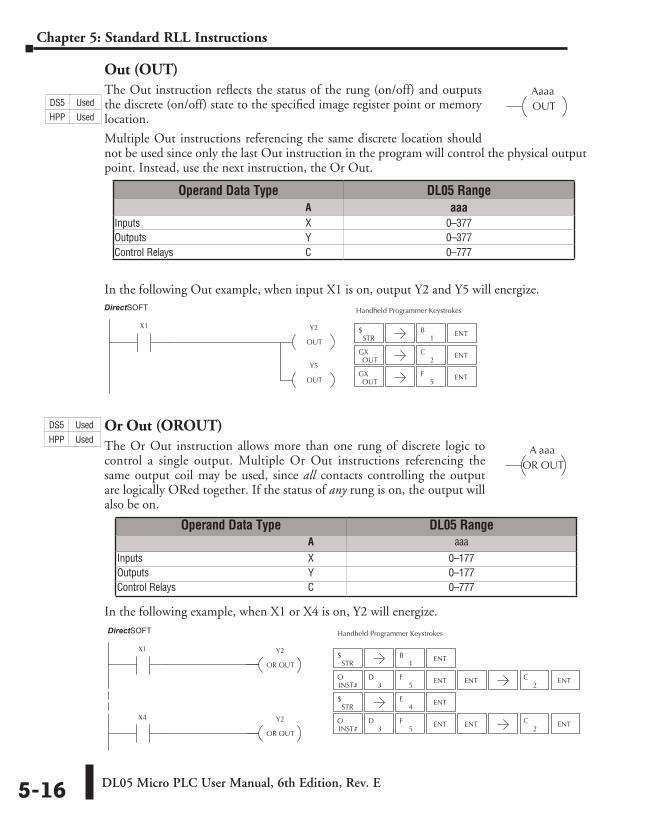
Out (OUT)The Out instruction reflects the status of the rung (on/off) and outputs the discrete (on/off) state to the specified image register point or memory location.
Multiple Out instructions referencing the same discrete location should not be used since only the last Out instruction in the program will control the physical output point. Instead, use the next instruction, the Or Out.
In the following Out example, when input X1 is on, output Y2 and Y5 will energize.
Or Out (OROUT)The Or Out instruction allows more than one rung of discrete logic to control a single output. Multiple Or Out instructions referencing the same output coil may be used, since all contacts controlling the output are logically ORed together. If the status of any rung is on, the output will also be on.
In the following example, when X1 or X4 is on, Y2 will energize.
AaaaOUT
STR$
1B ENT
STR$ ENT
4E
Y2
OR OUT
X1
Y2
OR OUT
X4
Handheld Programmer KeystrokesDirect SOFT32
INST#O
5F
3D ENT ENT
2C ENT
2C ENT
INST#O
5F
3D ENT ENT
A aaaOR OUT
Operand Data Type DL05 Range ⸠⸠⸠⸠⸠⸠⸠⸠⸠⸠⸠⸠⸠⸠⸠⸠⸠⸠⸠⸠⸠⸠⸠⸠⸠⸠⸠⸠⸠⸠⸠⸠⸠⸠⸠⸠⸠⸠⸠⸠⸠⸠⸠⸠⸠⸠⸠⸠⸠⸠⸠⸠⸠⸠⸠⸠⸠⸠⸠⸠⸠⸠⸠⸠⸠⸠⸠⸠⸠⸠⸠⸠⸠A aaaInputs ⸠⸠⸠⸠⸠⸠⸠⸠⸠⸠⸠⸠⸠⸠⸠⸠⸠⸠⸠⸠⸠⸠⸠⸠⸠⸠⸠⸠⸠⸠⸠⸠⸠⸠⸠⸠⸠⸠⸠⸠⸠⸠⸠⸠⸠⸠⸠⸠⸠⸠⸠⸠⸠⸠⸠⸠⸠⸠⸠⸠⸠⸠⸠⸠⸠X 0–377Outputs ⸠⸠⸠⸠⸠⸠⸠⸠⸠⸠⸠⸠⸠⸠⸠⸠⸠⸠⸠⸠⸠⸠⸠⸠⸠⸠⸠⸠⸠⸠⸠⸠⸠⸠⸠⸠⸠⸠⸠⸠⸠⸠⸠⸠⸠⸠⸠⸠⸠⸠⸠⸠⸠⸠⸠⸠⸠⸠⸠⸠⸠⸠⸠Y 0–377Control Relays ⸠⸠⸠⸠⸠⸠⸠⸠⸠⸠⸠⸠⸠⸠⸠⸠⸠⸠⸠⸠⸠⸠⸠⸠⸠⸠⸠⸠⸠⸠⸠⸠⸠⸠⸠⸠⸠⸠⸠⸠⸠⸠⸠⸠⸠⸠⸠⸠⸠⸠⸠⸠C 0–777
Operand Data Type DL05 Range ⸠⸠⸠⸠⸠⸠⸠⸠⸠⸠⸠⸠⸠⸠⸠⸠⸠⸠⸠⸠⸠⸠⸠⸠⸠⸠⸠⸠⸠⸠⸠⸠⸠⸠⸠⸠⸠⸠⸠⸠⸠⸠⸠⸠⸠⸠⸠⸠⸠⸠⸠⸠⸠⸠⸠⸠⸠⸠⸠⸠⸠⸠⸠⸠⸠⸠⸠⸠⸠⸠⸠⸠⸠A aaaInputs ⸠⸠⸠⸠⸠⸠⸠⸠⸠⸠⸠⸠⸠⸠⸠⸠⸠⸠⸠⸠⸠⸠⸠⸠⸠⸠⸠⸠⸠⸠⸠⸠⸠⸠⸠⸠⸠⸠⸠⸠⸠⸠⸠⸠⸠⸠⸠⸠⸠⸠⸠⸠⸠⸠⸠⸠⸠⸠⸠⸠⸠⸠⸠⸠⸠X 0–177Outputs ⸠⸠⸠⸠⸠⸠⸠⸠⸠⸠⸠⸠⸠⸠⸠⸠⸠⸠⸠⸠⸠⸠⸠⸠⸠⸠⸠⸠⸠⸠⸠⸠⸠⸠⸠⸠⸠⸠⸠⸠⸠⸠⸠⸠⸠⸠⸠⸠⸠⸠⸠⸠⸠⸠⸠⸠⸠⸠⸠⸠⸠⸠⸠Y 0–177Control Relays ⸠⸠⸠⸠⸠⸠⸠⸠⸠⸠⸠⸠⸠⸠⸠⸠⸠⸠⸠⸠⸠⸠⸠⸠⸠⸠⸠⸠⸠⸠⸠⸠⸠⸠⸠⸠⸠⸠⸠⸠⸠⸠⸠⸠⸠⸠⸠⸠⸠⸠⸠⸠C 0–777
DS5 Used
HPP Used
DirectSOFT
STR$
1B ENT
OUTGX
2C ENT
OUTGX ENT
5F
Y2
OUT
X1
Y5
OUT
Handheld Programmer KeystrokesDirect SOFT32DirectSOFT
DS5 Used
HPP Used
DL05 Micro PLC User Manual, 6th Edition, Rev. E 5-17
Chapter 5: Standard RLL Instructions
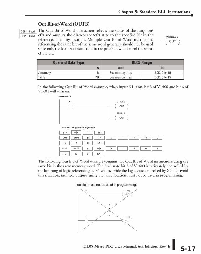
Out Bit-of-Word (OUTB)The Out Bit-of-Word instruction reflects the status of the rung (on/off) and outputs the discrete (on/off) state to the specified bit in the referenced memory location. Multiple Out Bit-of-Word instructions referencing the same bit of the same word generally should not be used since only the last Out instruction in the program will control the status of the bit.
In the following Out Bit-of-Word example, when input X1 is on, bit 3 of V1400 and bit 6 of V1401 will turn on.
The following Out Bit-of-Word example contains two Out Bit-of-Word instructions using the same bit in the same memory word. The final state bit 3 of V1400 is ultimately controlled by the last rung of logic referencing it. X1 will override the logic state controlled by X0. To avoid this situation, multiple outputs using the same location must not be used in programming.
Aaaa.bbOUT
B1400.3
OUT
X1
B1401.6
OUT
DirectSOFT 5
STR 1
Handheld Programmer Keystrokes
OUT V 1SHFT 4 0 0
3 ENTK
B
ENT
OUT V 1SHFT 4 0 1
6 ENTK
B
location must not be used in programming.
B1400.3
OUT
X0
B1400.3
OUT
X1
DS5 Used
HPP Used
Operand Data Type DL05 Range ⸠⸠⸠⸠⸠⸠⸠⸠⸠⸠⸠⸠⸠⸠⸠⸠⸠⸠⸠⸠⸠⸠⸠⸠⸠⸠⸠⸠⸠⸠⸠⸠⸠⸠⸠⸠⸠⸠⸠⸠⸠⸠⸠⸠⸠⸠⸠⸠⸠⸠⸠⸠⸠⸠⸠⸠⸠⸠⸠⸠⸠⸠⸠⸠⸠⸠⸠⸠⸠⸠⸠⸠⸠A aaa bbV-memory ⸠⸠⸠⸠⸠⸠⸠⸠⸠⸠⸠⸠⸠⸠⸠⸠⸠⸠⸠⸠⸠⸠⸠⸠⸠⸠⸠⸠⸠⸠⸠⸠⸠⸠⸠⸠⸠⸠⸠⸠⸠⸠⸠⸠⸠⸠⸠⸠⸠⸠⸠⸠⸠⸠⸠⸠⸠⸠B See memory map BCD, 0 to 15Pointer ⸠⸠⸠⸠⸠⸠⸠⸠⸠⸠⸠⸠⸠⸠⸠⸠⸠⸠⸠⸠⸠⸠⸠⸠⸠⸠⸠⸠⸠⸠⸠⸠⸠⸠⸠⸠⸠⸠⸠⸠⸠⸠⸠⸠⸠⸠⸠⸠⸠⸠⸠⸠⸠⸠⸠⸠⸠⸠⸠⸠⸠⸠PB See memory map BCD, 0 to 15
DL05 Micro PLC User Manual, 6th Edition, Rev. E5-18
Chapter 5: Standard RLL Instructions
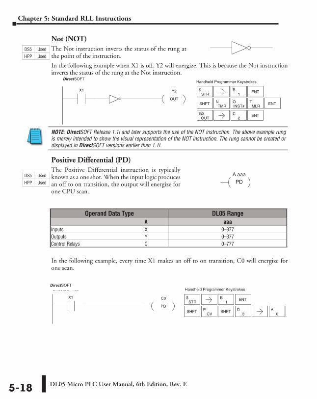
Not (NOT)The Not instruction inverts the status of the rung at the point of the instruction.
In the following example when X1 is off, Y2 will energize. This is because the Not instruction inverts the status of the rung at the Not instruction.
NOTE: DirectSOFT Release 1.1i and later supports the use of the NOT instruction. The above example rung is merely intended to show the visual representation of the NOT instruction. The rung cannot be created or displayed in DirectSOFT versions earlier than 1.1i.
Positive Differential (PD)The Positive Differential instruction is typically known as a one shot. When the input logic produces an off to on transition, the output will energize for one CPU scan.
In the following example, every time X1 makes an off to on transition, C0 will energize for one scan.
Y2
OUT
X1
Handheld Programmer KeystrokesDirectSOFT32
STR$
1B ENT
SHFTTMR
NINST#O
MLRT ENT
OUTGX
2C ENT
A aaaPD
Operand Data Type DL05 Range ⸠⸠⸠⸠⸠⸠⸠⸠⸠⸠⸠⸠⸠⸠⸠⸠⸠⸠⸠⸠⸠⸠⸠⸠⸠⸠⸠⸠⸠⸠⸠⸠⸠⸠⸠⸠⸠⸠⸠⸠⸠⸠⸠⸠⸠⸠⸠⸠⸠⸠⸠⸠⸠⸠⸠⸠⸠⸠⸠⸠⸠⸠⸠⸠⸠⸠⸠⸠⸠⸠⸠⸠⸠A aaaInputs ⸠⸠⸠⸠⸠⸠⸠⸠⸠⸠⸠⸠⸠⸠⸠⸠⸠⸠⸠⸠⸠⸠⸠⸠⸠⸠⸠⸠⸠⸠⸠⸠⸠⸠⸠⸠⸠⸠⸠⸠⸠⸠⸠⸠⸠⸠⸠⸠⸠⸠⸠⸠⸠⸠⸠⸠⸠⸠⸠⸠⸠⸠⸠⸠⸠ X 0–377Outputs ⸠⸠⸠⸠⸠⸠⸠⸠⸠⸠⸠⸠⸠⸠⸠⸠⸠⸠⸠⸠⸠⸠⸠⸠⸠⸠⸠⸠⸠⸠⸠⸠⸠⸠⸠⸠⸠⸠⸠⸠⸠⸠⸠⸠⸠⸠⸠⸠⸠⸠⸠⸠⸠⸠⸠⸠⸠⸠⸠⸠⸠⸠⸠Y 0–377Control Relays ⸠⸠⸠⸠⸠⸠⸠⸠⸠⸠⸠⸠⸠⸠⸠⸠⸠⸠⸠⸠⸠⸠⸠⸠⸠⸠⸠⸠⸠⸠⸠⸠⸠⸠⸠⸠⸠⸠⸠⸠⸠⸠⸠⸠⸠⸠⸠⸠⸠⸠⸠⸠C 0–777
STR$
1B ENT
SHFTCV
P3
DSHFT0
A ENT
C0
PD
X1
Handheld Programmer KeystrokesDirectSOFT32
DS5 Used
HPP Used
DS5 Used
HPP Used
DirectSOFT
DirectSOFT
DL05 Micro PLC User Manual, 6th Edition, Rev. E 5-19
Chapter 5: Standard RLL Instructions
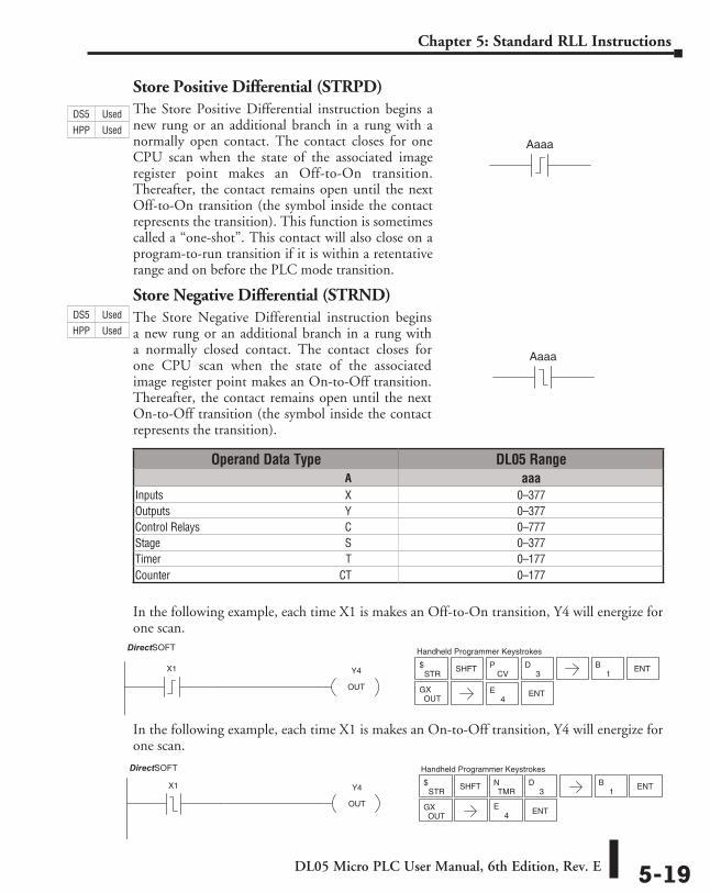
Store Positive Differential (STRPD)The Store Positive Differential instruction begins a new rung or an additional branch in a rung with a normally open contact. The contact closes for one CPU scan when the state of the associated image register point makes an Off-to-On transition. Thereafter, the contact remains open until the next Off-to-On transition (the symbol inside the contact represents the transition). This function is sometimes called a “one-shot”. This contact will also close on a program-to-run transition if it is within a retentative range and on before the PLC mode transition.
Store Negative Differential (STRND)The Store Negative Differential instruction begins a new rung or an additional branch in a rung with a normally closed contact. The contact closes for one CPU scan when the state of the associated image register point makes an On-to-Off transition. Thereafter, the contact remains open until the next On-to-Off transition (the symbol inside the contact represents the transition).
In the following example, each time X1 is makes an Off-to-On transition, Y4 will energize for one scan.
In the following example, each time X1 is makes an On-to-Off transition, Y4 will energize for one scan.
Aaaa
Aaaa
Operand Data Type DL05 Range ⸠⸠⸠⸠⸠⸠⸠⸠⸠⸠⸠⸠⸠⸠⸠⸠⸠⸠⸠⸠⸠⸠⸠⸠⸠⸠⸠⸠⸠⸠⸠⸠⸠⸠⸠⸠⸠⸠⸠⸠⸠⸠⸠⸠⸠⸠⸠⸠⸠⸠⸠⸠⸠⸠⸠⸠⸠⸠⸠⸠⸠⸠⸠⸠⸠⸠⸠⸠⸠⸠⸠⸠⸠A aaaInputs ⸠⸠⸠⸠⸠⸠⸠⸠⸠⸠⸠⸠⸠⸠⸠⸠⸠⸠⸠⸠⸠⸠⸠⸠⸠⸠⸠⸠⸠⸠⸠⸠⸠⸠⸠⸠⸠⸠⸠⸠⸠⸠⸠⸠⸠⸠⸠⸠⸠⸠⸠⸠⸠⸠⸠⸠⸠⸠⸠⸠⸠⸠⸠⸠⸠X 0–377Outputs ⸠⸠⸠⸠⸠⸠⸠⸠⸠⸠⸠⸠⸠⸠⸠⸠⸠⸠⸠⸠⸠⸠⸠⸠⸠⸠⸠⸠⸠⸠⸠⸠⸠⸠⸠⸠⸠⸠⸠⸠⸠⸠⸠⸠⸠⸠⸠⸠⸠⸠⸠⸠⸠⸠⸠⸠⸠⸠⸠⸠⸠⸠⸠Y 0–377Control Relays ⸠⸠⸠⸠⸠⸠⸠⸠⸠⸠⸠⸠⸠⸠⸠⸠⸠⸠⸠⸠⸠⸠⸠⸠⸠⸠⸠⸠⸠⸠⸠⸠⸠⸠⸠⸠⸠⸠⸠⸠⸠⸠⸠⸠⸠⸠⸠⸠⸠⸠⸠⸠C 0–777Stage ⸠⸠⸠⸠⸠⸠⸠⸠⸠⸠⸠⸠⸠⸠⸠⸠⸠⸠⸠⸠⸠⸠⸠⸠⸠⸠⸠⸠⸠⸠⸠⸠⸠⸠⸠⸠⸠⸠⸠⸠⸠⸠⸠⸠⸠⸠⸠⸠⸠⸠⸠⸠⸠⸠⸠⸠⸠⸠⸠⸠⸠⸠⸠⸠⸠⸠S 0–377Timer ⸠⸠⸠⸠⸠⸠⸠⸠⸠⸠⸠⸠⸠⸠⸠⸠⸠⸠⸠⸠⸠⸠⸠⸠⸠⸠⸠⸠⸠⸠⸠⸠⸠⸠⸠⸠⸠⸠⸠⸠⸠⸠⸠⸠⸠⸠⸠⸠⸠⸠⸠⸠⸠⸠⸠⸠⸠⸠⸠⸠⸠⸠⸠⸠⸠⸠ T 0–177Counter ⸠⸠⸠⸠⸠⸠⸠⸠⸠⸠⸠⸠⸠⸠⸠⸠⸠⸠⸠⸠⸠⸠⸠⸠⸠⸠⸠⸠⸠⸠⸠⸠⸠⸠⸠⸠⸠⸠⸠⸠⸠⸠⸠⸠⸠⸠⸠⸠⸠⸠⸠⸠⸠⸠⸠⸠⸠⸠⸠⸠⸠CT 0–177
Y4
OUT
DirectSOFT32
X1STR
$CV
P
ENTOUT
GX
3DSHFT
1B ENT
Handheld Programmer Keystrokes
4E
Y4
OUT
DirectSOFT32
X1STR
$TMR
N
ENTOUT
GX
3DSHFT
1B ENT
Handheld Programmer Keystrokes
4E
DS5 Used
HPP Used
DS5 Used
HPP Used
DirectSOFT
DirectSOFT
DL05 Micro PLC User Manual, 6th Edition, Rev. E5-20
Chapter 5: Standard RLL Instructions
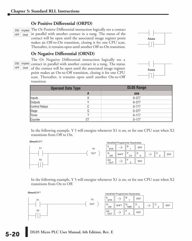
Or Positive Differential (ORPD)The Or Positive Differential instruction logically ors a contact in parallel with another contact in a rung. The status of the contact will be open until the associated image register point makes an Off-to-On transition, closing it for one CPU scan. Thereafter, it remains open until another Off-to-On transition.
Or Negative Differential (ORND)The Or Negative Differential instruction logically ors a contact in parallel with another contact in a rung. The status of the contact will be open until the associated image register point makes an On-to-Off transition, closing it for one CPU scan. Thereafter, it remains open until another On-to-Off transition.
In the following example, Y 5 will energize whenever X1 is on, or for one CPU scan when X2 transitions from Off to On.
In the following example, Y 5 will energize whenever X1 is on, or for one CPU scan when X2 transitions from On to Off.
Aaaa
Aaaa
Operand Data Type DL05 Range ⸠⸠⸠⸠⸠⸠⸠⸠⸠⸠⸠⸠⸠⸠⸠⸠⸠⸠⸠⸠⸠⸠⸠⸠⸠⸠⸠⸠⸠⸠⸠⸠⸠⸠⸠⸠⸠⸠⸠⸠⸠⸠⸠⸠⸠⸠⸠⸠⸠⸠⸠⸠⸠⸠⸠⸠⸠⸠⸠⸠⸠⸠⸠⸠⸠⸠⸠⸠⸠⸠⸠⸠⸠A aaaInputs ⸠⸠⸠⸠⸠⸠⸠⸠⸠⸠⸠⸠⸠⸠⸠⸠⸠⸠⸠⸠⸠⸠⸠⸠⸠⸠⸠⸠⸠⸠⸠⸠⸠⸠⸠⸠⸠⸠⸠⸠⸠⸠⸠⸠⸠⸠⸠⸠⸠⸠⸠⸠⸠⸠⸠⸠⸠⸠⸠⸠⸠⸠⸠⸠⸠X 0–377Outputs ⸠⸠⸠⸠⸠⸠⸠⸠⸠⸠⸠⸠⸠⸠⸠⸠⸠⸠⸠⸠⸠⸠⸠⸠⸠⸠⸠⸠⸠⸠⸠⸠⸠⸠⸠⸠⸠⸠⸠⸠⸠⸠⸠⸠⸠⸠⸠⸠⸠⸠⸠⸠⸠⸠⸠⸠⸠⸠⸠⸠⸠⸠⸠Y 0–377Control Relays ⸠⸠⸠⸠⸠⸠⸠⸠⸠⸠⸠⸠⸠⸠⸠⸠⸠⸠⸠⸠⸠⸠⸠⸠⸠⸠⸠⸠⸠⸠⸠⸠⸠⸠⸠⸠⸠⸠⸠⸠⸠⸠⸠⸠⸠⸠⸠⸠⸠⸠⸠⸠C 0–777Stage ⸠⸠⸠⸠⸠⸠⸠⸠⸠⸠⸠⸠⸠⸠⸠⸠⸠⸠⸠⸠⸠⸠⸠⸠⸠⸠⸠⸠⸠⸠⸠⸠⸠⸠⸠⸠⸠⸠⸠⸠⸠⸠⸠⸠⸠⸠⸠⸠⸠⸠⸠⸠⸠⸠⸠⸠⸠⸠⸠⸠⸠⸠⸠⸠⸠⸠S 0–377Timer ⸠⸠⸠⸠⸠⸠⸠⸠⸠⸠⸠⸠⸠⸠⸠⸠⸠⸠⸠⸠⸠⸠⸠⸠⸠⸠⸠⸠⸠⸠⸠⸠⸠⸠⸠⸠⸠⸠⸠⸠⸠⸠⸠⸠⸠⸠⸠⸠⸠⸠⸠⸠⸠⸠⸠⸠⸠⸠⸠⸠⸠⸠⸠⸠⸠⸠ T 0–177Counter ⸠⸠⸠⸠⸠⸠⸠⸠⸠⸠⸠⸠⸠⸠⸠⸠⸠⸠⸠⸠⸠⸠⸠⸠⸠⸠⸠⸠⸠⸠⸠⸠⸠⸠⸠⸠⸠⸠⸠⸠⸠⸠⸠⸠⸠⸠⸠⸠⸠⸠⸠⸠⸠⸠⸠⸠⸠⸠⸠⸠⸠CT 0–177
Y5
OUT
X1
DirectSOFT32
X2
STR$
CVP
ENTOUT
GX
3DSHFT
1B ENT
Handheld Programmer Keystrokes
5F
ORQ
2C ENT
X1 Y5
OUT
DirectSOFT32
X2
STR$
TMRN
ENTOUT
GX
3DSHFT
1B ENT
Handheld Programmer Keystrokes
5F
ORQ
2C ENT
DS5 Implied
HPP Used
DS5 Implied
HPP Used
DirectSOFT
DirectSOFT
DL05 Micro PLC User Manual, 6th Edition, Rev. E 5-21
Chapter 5: Standard RLL Instructions
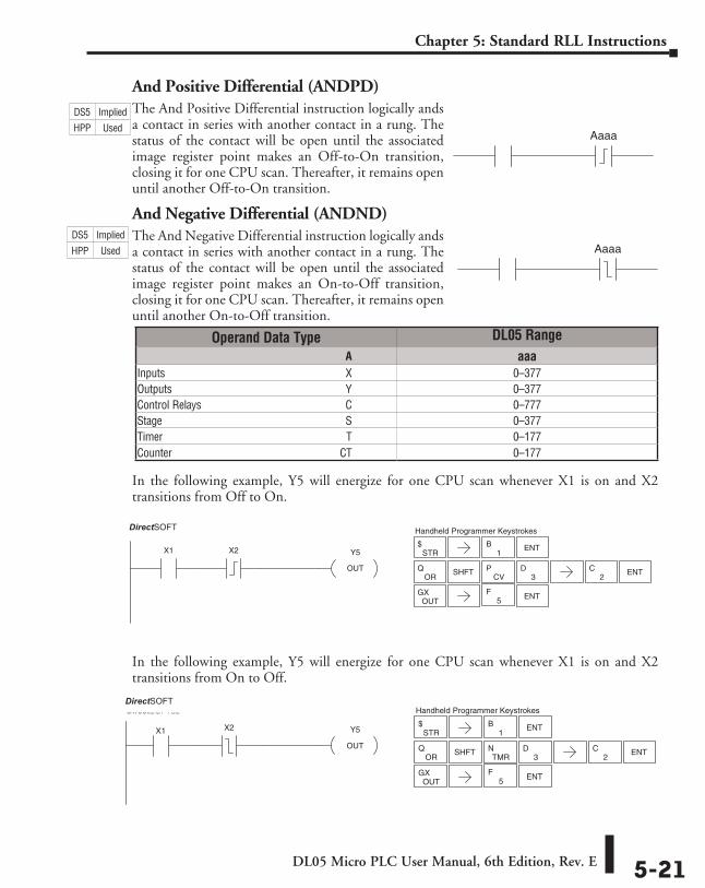
And Positive Differential (ANDPD)The And Positive Differential instruction logically ands a contact in series with another contact in a rung. The status of the contact will be open until the associated image register point makes an Off-to-On transition, closing it for one CPU scan. Thereafter, it remains open until another Off-to-On transition.
And Negative Differential (ANDND)The And Negative Differential instruction logically ands a contact in series with another contact in a rung. The status of the contact will be open until the associated image register point makes an On-to-Off transition, closing it for one CPU scan. Thereafter, it remains open until another On-to-Off transition.
In the following example, Y5 will energize for one CPU scan whenever X1 is on and X2 transitions from Off to On.
In the following example, Y5 will energize for one CPU scan whenever X1 is on and X2 transitions from On to Off.
Operand Data Type DL05 Range ⸠⸠⸠⸠⸠⸠⸠⸠⸠⸠⸠⸠⸠⸠⸠⸠⸠⸠⸠⸠⸠⸠⸠⸠⸠⸠⸠⸠⸠⸠⸠⸠⸠⸠⸠⸠⸠⸠⸠⸠⸠⸠⸠⸠⸠⸠⸠⸠⸠⸠⸠⸠⸠⸠⸠⸠⸠⸠⸠⸠⸠⸠⸠⸠⸠⸠⸠⸠⸠⸠⸠⸠⸠A aaaInputs ⸠⸠⸠⸠⸠⸠⸠⸠⸠⸠⸠⸠⸠⸠⸠⸠⸠⸠⸠⸠⸠⸠⸠⸠⸠⸠⸠⸠⸠⸠⸠⸠⸠⸠⸠⸠⸠⸠⸠⸠⸠⸠⸠⸠⸠⸠⸠⸠⸠⸠⸠⸠⸠⸠⸠⸠⸠⸠⸠⸠⸠⸠⸠⸠⸠X 0–377Outputs ⸠⸠⸠⸠⸠⸠⸠⸠⸠⸠⸠⸠⸠⸠⸠⸠⸠⸠⸠⸠⸠⸠⸠⸠⸠⸠⸠⸠⸠⸠⸠⸠⸠⸠⸠⸠⸠⸠⸠⸠⸠⸠⸠⸠⸠⸠⸠⸠⸠⸠⸠⸠⸠⸠⸠⸠⸠⸠⸠⸠⸠⸠⸠Y 0–377Control Relays ⸠⸠⸠⸠⸠⸠⸠⸠⸠⸠⸠⸠⸠⸠⸠⸠⸠⸠⸠⸠⸠⸠⸠⸠⸠⸠⸠⸠⸠⸠⸠⸠⸠⸠⸠⸠⸠⸠⸠⸠⸠⸠⸠⸠⸠⸠⸠⸠⸠⸠⸠⸠C 0–777Stage ⸠⸠⸠⸠⸠⸠⸠⸠⸠⸠⸠⸠⸠⸠⸠⸠⸠⸠⸠⸠⸠⸠⸠⸠⸠⸠⸠⸠⸠⸠⸠⸠⸠⸠⸠⸠⸠⸠⸠⸠⸠⸠⸠⸠⸠⸠⸠⸠⸠⸠⸠⸠⸠⸠⸠⸠⸠⸠⸠⸠⸠⸠⸠⸠⸠⸠S 0–377Timer ⸠⸠⸠⸠⸠⸠⸠⸠⸠⸠⸠⸠⸠⸠⸠⸠⸠⸠⸠⸠⸠⸠⸠⸠⸠⸠⸠⸠⸠⸠⸠⸠⸠⸠⸠⸠⸠⸠⸠⸠⸠⸠⸠⸠⸠⸠⸠⸠⸠⸠⸠⸠⸠⸠⸠⸠⸠⸠⸠⸠⸠⸠⸠⸠⸠⸠ T 0–177Counter ⸠⸠⸠⸠⸠⸠⸠⸠⸠⸠⸠⸠⸠⸠⸠⸠⸠⸠⸠⸠⸠⸠⸠⸠⸠⸠⸠⸠⸠⸠⸠⸠⸠⸠⸠⸠⸠⸠⸠⸠⸠⸠⸠⸠⸠⸠⸠⸠⸠⸠⸠⸠⸠⸠⸠⸠⸠⸠⸠⸠⸠CT 0–177
Aaaa
Aaaa
Y5
OUT
X1
DirectSOFT32
X2 STR$
CVP
ENTOUT
GX
3DSHFT
1B ENT
Handheld Programmer Keystrokes
5F
ORQ
2C ENT
X1 Y5
OUT
DirectSOFT32
X2STR
$
TMRN
ENTOUT
GX
3DSHFT
1B ENT
Handheld Programmer Keystrokes
5F
ORQ
2C ENT
DS5 Implied
HPP Used
DS5 Implied
HPP Used
DirectSOFT
DirectSOFT
DL05 Micro PLC User Manual, 6th Edition, Rev. E5-22
Chapter 5: Standard RLL Instructions
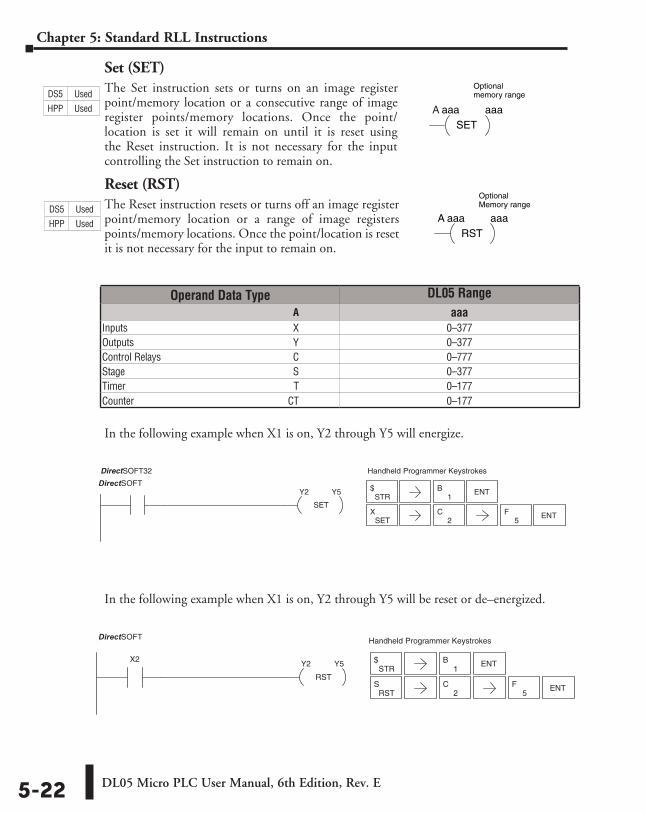
Set (SET)The Set instruction sets or turns on an image register point/memory location or a consecutive range of image register points/memory locations. Once the point/location is set it will remain on until it is reset using the Reset instruction. It is not necessary for the input controlling the Set instruction to remain on.
Reset (RST)The Reset instruction resets or turns off an image register point/memory location or a range of image registers points/memory locations. Once the point/location is reset it is not necessary for the input to remain on.
In the following example when X1 is on, Y2 through Y5 will energize.
In the following example when X1 is on, Y2 through Y5 will be reset or de–energized.
SET
X1 Y2 Y5
Handheld Programmer KeystrokesDirectSOFT32
STR$
1B ENT
SETX ENT
2C
5F
STR$
1B ENT
RSTS
2C
RST
X2 Y2 Y5
Handheld Programmer KeystrokesDirectSOFT32
ENT5
F
A aaaSET
aaa
Optional memory range
A aaaRST
aaa
Optional Memory range.
Operand Data Type DL05 Range ⸠⸠⸠⸠⸠⸠⸠⸠⸠⸠⸠⸠⸠⸠⸠⸠⸠⸠⸠⸠⸠⸠⸠⸠⸠⸠⸠⸠⸠⸠⸠⸠⸠⸠⸠⸠⸠⸠⸠⸠⸠⸠⸠⸠⸠⸠⸠⸠⸠⸠⸠⸠⸠⸠⸠⸠⸠⸠⸠⸠⸠⸠⸠⸠⸠⸠⸠⸠⸠⸠⸠⸠⸠A aaaInputs ⸠⸠⸠⸠⸠⸠⸠⸠⸠⸠⸠⸠⸠⸠⸠⸠⸠⸠⸠⸠⸠⸠⸠⸠⸠⸠⸠⸠⸠⸠⸠⸠⸠⸠⸠⸠⸠⸠⸠⸠⸠⸠⸠⸠⸠⸠⸠⸠⸠⸠⸠⸠⸠⸠⸠⸠⸠⸠⸠⸠⸠⸠⸠⸠⸠X 0–377Outputs ⸠⸠⸠⸠⸠⸠⸠⸠⸠⸠⸠⸠⸠⸠⸠⸠⸠⸠⸠⸠⸠⸠⸠⸠⸠⸠⸠⸠⸠⸠⸠⸠⸠⸠⸠⸠⸠⸠⸠⸠⸠⸠⸠⸠⸠⸠⸠⸠⸠⸠⸠⸠⸠⸠⸠⸠⸠⸠⸠⸠⸠⸠⸠Y 0–377Control Relays ⸠⸠⸠⸠⸠⸠⸠⸠⸠⸠⸠⸠⸠⸠⸠⸠⸠⸠⸠⸠⸠⸠⸠⸠⸠⸠⸠⸠⸠⸠⸠⸠⸠⸠⸠⸠⸠⸠⸠⸠⸠⸠⸠⸠⸠⸠⸠⸠⸠⸠⸠⸠C 0–777Stage ⸠⸠⸠⸠⸠⸠⸠⸠⸠⸠⸠⸠⸠⸠⸠⸠⸠⸠⸠⸠⸠⸠⸠⸠⸠⸠⸠⸠⸠⸠⸠⸠⸠⸠⸠⸠⸠⸠⸠⸠⸠⸠⸠⸠⸠⸠⸠⸠⸠⸠⸠⸠⸠⸠⸠⸠⸠⸠⸠⸠⸠⸠⸠⸠⸠⸠S 0–377Timer ⸠⸠⸠⸠⸠⸠⸠⸠⸠⸠⸠⸠⸠⸠⸠⸠⸠⸠⸠⸠⸠⸠⸠⸠⸠⸠⸠⸠⸠⸠⸠⸠⸠⸠⸠⸠⸠⸠⸠⸠⸠⸠⸠⸠⸠⸠⸠⸠⸠⸠⸠⸠⸠⸠⸠⸠⸠⸠⸠⸠⸠⸠⸠⸠⸠⸠ T 0–177Counter ⸠⸠⸠⸠⸠⸠⸠⸠⸠⸠⸠⸠⸠⸠⸠⸠⸠⸠⸠⸠⸠⸠⸠⸠⸠⸠⸠⸠⸠⸠⸠⸠⸠⸠⸠⸠⸠⸠⸠⸠⸠⸠⸠⸠⸠⸠⸠⸠⸠⸠⸠⸠⸠⸠⸠⸠⸠⸠⸠⸠⸠CT 0–177
DS5 Used
HPP Used
DS5 Used
HPP Used
DirectSOFT
DirectSOFT
DL05 Micro PLC User Manual, 6th Edition, Rev. E 5-23
Chapter 5: Standard RLL Instructions
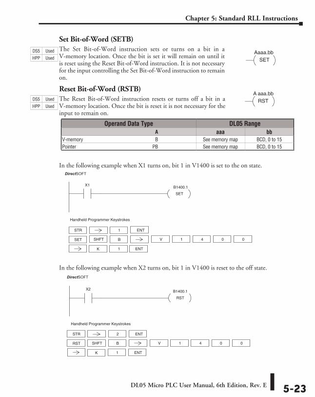
Set Bit-of-Word (SETB)The Set Bit-of-Word instruction sets or turns on a bit in a V-memory location. Once the bit is set it will remain on until it is reset using the Reset Bit-of-Word instruction. It is not necessary for the input controlling the Set Bit-of-Word instruction to remain on.
Reset Bit-of-Word (RSTB)The Reset Bit-of-Word instruction resets or turns off a bit in a V-memory location. Once the bit is reset it is not necessary for the input to remain on.
In the following example when X1 turns on, bit 1 in V1400 is set to the on state.
In the following example when X2 turns on, bit 1 in V1400 is reset to the off state.
Aaaa.bbSET
A aaa.bbRST
SET
X1 B1400.1
DirectSOFT32
STR 1
Handheld Programmer Keystrokes
SET V 1SHFT 4 0 0
1 ENTK
B
ENT
RST
X2 B1400.1
DirectSOFT32
Handheld Programmer Keystrokes
STR 2
RST V 1SHFT 4 0 0
1 ENTK
B
ENT
Operand Data Type DL05 Range ⸠⸠⸠⸠⸠⸠⸠⸠⸠⸠⸠⸠⸠⸠⸠⸠⸠⸠⸠⸠⸠⸠⸠⸠⸠⸠⸠⸠⸠⸠⸠⸠⸠⸠⸠⸠⸠⸠⸠⸠⸠⸠⸠⸠⸠⸠⸠⸠⸠⸠⸠⸠⸠⸠⸠⸠⸠⸠⸠⸠⸠⸠⸠⸠⸠⸠⸠⸠⸠⸠⸠⸠⸠A aaa bbV-memory ⸠⸠⸠⸠⸠⸠⸠⸠⸠⸠⸠⸠⸠⸠⸠⸠⸠⸠⸠⸠⸠⸠⸠⸠⸠⸠⸠⸠⸠⸠⸠⸠⸠⸠⸠⸠⸠⸠⸠⸠⸠⸠⸠⸠⸠⸠⸠⸠⸠⸠⸠⸠⸠⸠⸠⸠⸠⸠B See memory map BCD, 0 to 15Pointer ⸠⸠⸠⸠⸠⸠⸠⸠⸠⸠⸠⸠⸠⸠⸠⸠⸠⸠⸠⸠⸠⸠⸠⸠⸠⸠⸠⸠⸠⸠⸠⸠⸠⸠⸠⸠⸠⸠⸠⸠⸠⸠⸠⸠⸠⸠⸠⸠⸠⸠⸠⸠⸠⸠⸠⸠⸠⸠⸠⸠⸠⸠PB See memory map BCD, 0 to 15
DS5 Used
HPP Used
DS5 Used
HPP Used
DirectSOFT
DirectSOFT
DL05 Micro PLC User Manual, 6th Edition, Rev. E5-24
Chapter 5: Standard RLL Instructions
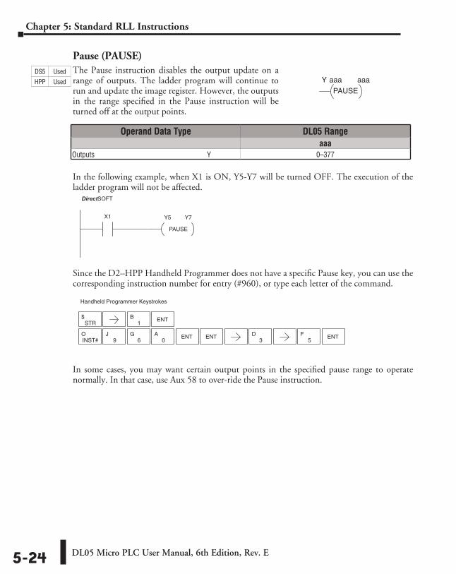
Pause (PAUSE)The Pause instruction disables the output update on a range of outputs. The ladder program will continue to run and update the image register. However, the outputs in the range specified in the Pause instruction will be turned off at the output points.
In the following example, when X1 is ON, Y5-Y7 will be turned OFF. The execution of the ladder program will not be affected.
Since the D2–HPP Handheld Programmer does not have a specific Pause key, you can use the corresponding instruction number for entry (#960), or type each letter of the command.
In some cases, you may want certain output points in the specified pause range to operate normally. In that case, use Aux 58 to over-ride the Pause instruction.
aaaaaaY
PAUSE
Operand Data Type DL05 Rangeaaa
Outputs ⸠⸠⸠⸠⸠⸠⸠⸠⸠⸠⸠⸠⸠⸠⸠⸠⸠⸠⸠⸠⸠⸠⸠⸠⸠⸠⸠⸠⸠⸠⸠⸠⸠⸠⸠⸠⸠⸠⸠⸠⸠⸠⸠⸠⸠⸠⸠⸠⸠⸠⸠⸠⸠⸠⸠⸠⸠⸠⸠⸠⸠⸠⸠Y 0–377
DirectSOFT32
PAUSE
X1 Y5 Y7
STR$
1B ENT
Handheld Programmer Keystrokes
5F ENT
INST#O
9J
6G
0A ENT ENT
3D
DS5 Used
HPP Used
DirectSOFT
DL05 Micro PLC User Manual, 6th Edition, Rev. E 5-25
Chapter 5: Standard RLL Instructions
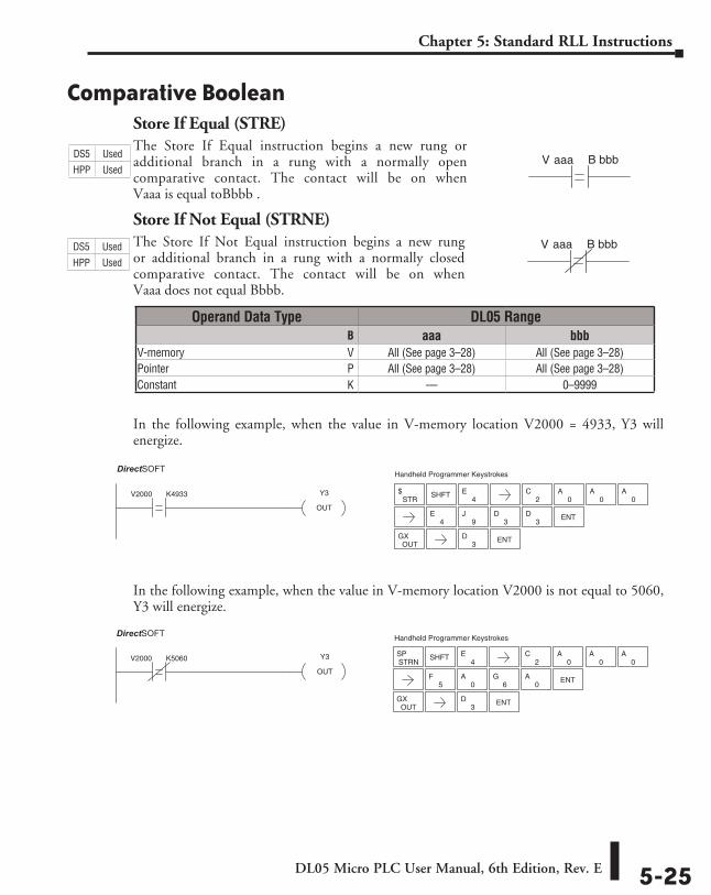
Comparative BooleanStore If Equal (STRE)The Store If Equal instruction begins a new rung or additional branch in a rung with a normally open comparative contact. The contact will be on when Vaaa is equal toBbbb .
Store If Not Equal (STRNE)The Store If Not Equal instruction begins a new rung or additional branch in a rung with a normally closed comparative contact. The contact will be on when Vaaa does not equal Bbbb.
In the following example, when the value in V-memory location V2000 = 4933, Y3 will energize.
In the following example, when the value in V-memory location V2000 is not equal to 5060, Y3 will energize.
V aaa B bbb
V aaa B bbb
Operand Data Type DL05 Range ⸠⸠⸠⸠⸠⸠⸠⸠⸠⸠⸠⸠⸠⸠⸠⸠⸠⸠⸠⸠⸠⸠⸠⸠⸠⸠⸠⸠⸠⸠⸠⸠⸠⸠⸠⸠⸠⸠⸠⸠⸠⸠⸠⸠⸠⸠⸠⸠⸠⸠⸠⸠⸠⸠⸠⸠⸠⸠⸠⸠⸠⸠⸠⸠⸠⸠⸠⸠⸠⸠⸠⸠⸠B aaa bbbV-memory ⸠⸠⸠⸠⸠⸠⸠⸠⸠⸠⸠⸠⸠⸠⸠⸠⸠⸠⸠⸠⸠⸠⸠⸠⸠⸠⸠⸠⸠⸠⸠⸠⸠⸠⸠⸠⸠⸠⸠⸠⸠⸠⸠⸠⸠⸠⸠⸠⸠⸠⸠⸠⸠⸠⸠⸠⸠⸠V All (See page 3–28) All (See page 3–28)Pointer ⸠⸠⸠⸠⸠⸠⸠⸠⸠⸠⸠⸠⸠⸠⸠⸠⸠⸠⸠⸠⸠⸠⸠⸠⸠⸠⸠⸠⸠⸠⸠⸠⸠⸠⸠⸠⸠⸠⸠⸠⸠⸠⸠⸠⸠⸠⸠⸠⸠⸠⸠⸠⸠⸠⸠⸠⸠⸠⸠⸠⸠⸠⸠⸠P All (See page 3–28) All (See page 3–28)Constant ⸠⸠⸠⸠⸠⸠⸠⸠⸠⸠⸠⸠⸠⸠⸠⸠⸠⸠⸠⸠⸠⸠⸠⸠⸠⸠⸠⸠⸠⸠⸠⸠⸠⸠⸠⸠⸠⸠⸠⸠⸠⸠⸠⸠⸠⸠⸠⸠⸠⸠⸠⸠⸠⸠⸠⸠⸠⸠⸠⸠⸠K –– 0–9999
V2000 K4933 Y3
OUT
DirectSOFT32 Handheld Programmer Keystrokes
STR$ SHFT
4E
2C
0A
0A
0A
4E
9J
3D
3D ENT
OUTGX ENT
3D
Y3
OUT
V2000 K5060
DirectSOFT32 Handheld Programmer Keystrokes
SHFT
OUTGX ENT
3D
4E
2C
0A
0A
0A
STRNSP
5F
0A ENT
6G
0A
DS5 Used
HPP Used
DS5 Used
HPP Used
DirectSOFT
DirectSOFT
DL05 Micro PLC User Manual, 6th Edition, Rev. E5-26
Chapter 5: Standard RLL Instructions
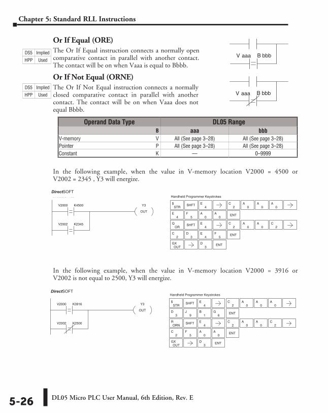
Or If Equal (ORE)The Or If Equal instruction connects a normally open comparative contact in parallel with another contact. The contact will be on when Vaaa is equal to Bbbb.
Or If Not Equal (ORNE)The Or If Not Equal instruction connects a normally closed comparative contact in parallel with another contact. The contact will be on when Vaaa does not equal Bbbb.
In the following example, when the value in V-memory location V2000 = 4500 or V2002 = 2345 , Y3 will energize.
In the following example, when the value in V-memory location V2000 = 3916 or V2002 is not equal to 2500, Y3 will energize.
Operand Data Type DL05 Range ⸠⸠⸠⸠⸠⸠⸠⸠⸠⸠⸠⸠⸠⸠⸠⸠⸠⸠⸠⸠⸠⸠⸠⸠⸠⸠⸠⸠⸠⸠⸠⸠⸠⸠⸠⸠⸠⸠⸠⸠⸠⸠⸠⸠⸠⸠⸠⸠⸠⸠⸠⸠⸠⸠⸠⸠⸠⸠⸠⸠⸠⸠⸠⸠⸠⸠⸠⸠⸠⸠⸠⸠⸠B aaa bbbV-memory ⸠⸠⸠⸠⸠⸠⸠⸠⸠⸠⸠⸠⸠⸠⸠⸠⸠⸠⸠⸠⸠⸠⸠⸠⸠⸠⸠⸠⸠⸠⸠⸠⸠⸠⸠⸠⸠⸠⸠⸠⸠⸠⸠⸠⸠⸠⸠⸠⸠⸠⸠⸠⸠⸠⸠⸠⸠⸠V All (See page 3–28) All (See page 3–28)Pointer ⸠⸠⸠⸠⸠⸠⸠⸠⸠⸠⸠⸠⸠⸠⸠⸠⸠⸠⸠⸠⸠⸠⸠⸠⸠⸠⸠⸠⸠⸠⸠⸠⸠⸠⸠⸠⸠⸠⸠⸠⸠⸠⸠⸠⸠⸠⸠⸠⸠⸠⸠⸠⸠⸠⸠⸠⸠⸠⸠⸠⸠⸠⸠⸠P All (See page 3–28) All (See page 3–28)Constant ⸠⸠⸠⸠⸠⸠⸠⸠⸠⸠⸠⸠⸠⸠⸠⸠⸠⸠⸠⸠⸠⸠⸠⸠⸠⸠⸠⸠⸠⸠⸠⸠⸠⸠⸠⸠⸠⸠⸠⸠⸠⸠⸠⸠⸠⸠⸠⸠⸠⸠⸠⸠⸠⸠⸠⸠⸠⸠⸠⸠⸠K –– 0–9999
V aaa B bbb
V aaa B bbbDS5 Implied
HPP Used
DS5 Implied
HPP Used
2C
5F ENT
0A
0A
3D
9J ENT
1B
6G
4E
Y3
OUT
V2000 K3916
V2002 K2500
DirectSOFT32 Handheld Programmer Keystrokes
STR$ SHFT
2C
0A
0A
0A
ORNR SHFT
4E
2C
0A
0A
2C
OUTGX ENT
3D
DirectSOFT
2C
3D
4E
5F ENT
4E
5F ENT
0A
0A
Y3
OUT
V2002 K2345
V2000 K4500
DirectSOFT32 Handheld Programmer Keystrokes
SHFT4
E2
C0
A0
A0
ASTR
$
ORQ SHFT
4E
2C
0A
0A
2C
OUTGX ENT
3D
DirectSOFT
DL05 Micro PLC User Manual, 6th Edition, Rev. E 5-27
Chapter 5: Standard RLL Instructions
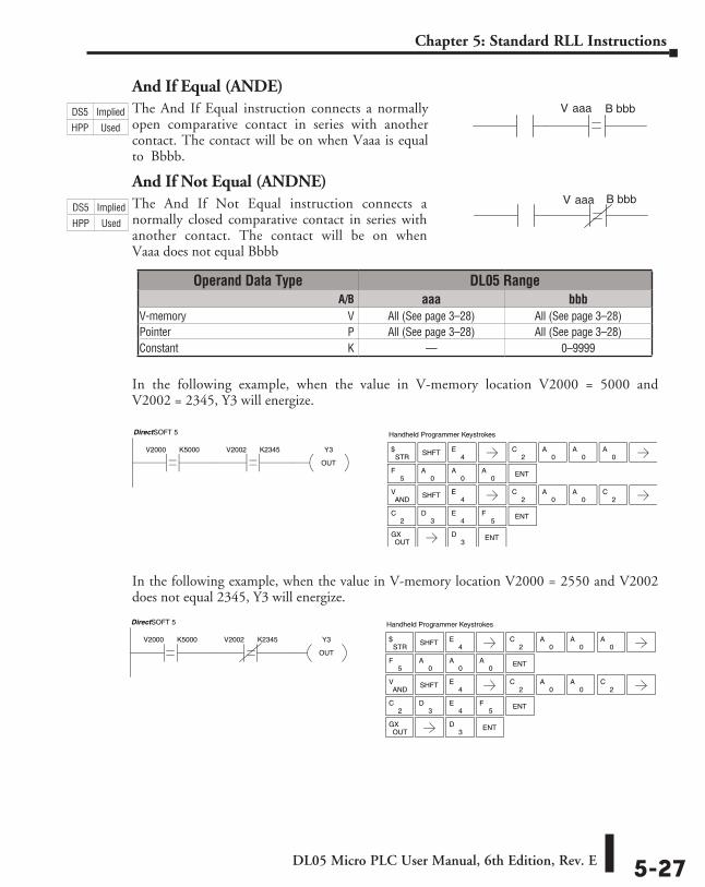
And If Equal (ANDE)The And If Equal instruction connects a normally open comparative contact in series with another contact. The contact will be on when Vaaa is equal to Bbbb.
And If Not Equal (ANDNE)The And If Not Equal instruction connects a normally closed comparative contact in series with another contact. The contact will be on when Vaaa does not equal Bbbb
In the following example, when the value in V-memory location V2000 = 5000 and V2002 = 2345, Y3 will energize.
In the following example, when the value in V-memory location V2000 = 2550 and V2002 does not equal 2345, Y3 will energize.
V aaa B bbb
V aaa B bbb
2C
3D
4E
5F ENT
5F
0A ENT
0A
0A
2C
STR$ SHFT
4E
0A
0A
0A
ANDV SHFT
4EE
2C
0A
0A
2C
OUTGX ENT
3D
Y3
OUT
V2002 K2345V2000 K5000
DirectSOFT 5 Handheld Programmer Keystrokes
2C
3D
4E
5F ENT
5F
0A ENT
0A
0A
2C
STR$ SHFT
4E
0A
0A
0A
ANDV SHFT
4E
2C
0A
0A
2C
OUTGX ENT
3D
Y3
OUT
V2002 K2345V2000 K5000
DirectSOFT 5 Handheld Programmer Keystrokes
Operand Data Type DL05 Range ⸠⸠⸠⸠⸠⸠⸠⸠⸠⸠⸠⸠⸠⸠⸠⸠⸠⸠⸠⸠⸠⸠⸠⸠⸠⸠⸠⸠⸠⸠⸠⸠⸠⸠⸠⸠⸠⸠⸠⸠⸠⸠⸠⸠⸠⸠⸠⸠⸠⸠⸠⸠⸠⸠⸠⸠⸠⸠⸠⸠⸠⸠⸠⸠⸠⸠⸠⸠⸠ A/B aaa bbbV-memory ⸠⸠⸠⸠⸠⸠⸠⸠⸠⸠⸠⸠⸠⸠⸠⸠⸠⸠⸠⸠⸠⸠⸠⸠⸠⸠⸠⸠⸠⸠⸠⸠⸠⸠⸠⸠⸠⸠⸠⸠⸠⸠⸠⸠⸠⸠⸠⸠⸠⸠⸠⸠⸠⸠⸠⸠⸠⸠V All (See page 3–28) All (See page 3–28)Pointer ⸠⸠⸠⸠⸠⸠⸠⸠⸠⸠⸠⸠⸠⸠⸠⸠⸠⸠⸠⸠⸠⸠⸠⸠⸠⸠⸠⸠⸠⸠⸠⸠⸠⸠⸠⸠⸠⸠⸠⸠⸠⸠⸠⸠⸠⸠⸠⸠⸠⸠⸠⸠⸠⸠⸠⸠⸠⸠⸠⸠⸠⸠⸠⸠P All (See page 3–28) All (See page 3–28)Constant ⸠⸠⸠⸠⸠⸠⸠⸠⸠⸠⸠⸠⸠⸠⸠⸠⸠⸠⸠⸠⸠⸠⸠⸠⸠⸠⸠⸠⸠⸠⸠⸠⸠⸠⸠⸠⸠⸠⸠⸠⸠⸠⸠⸠⸠⸠⸠⸠⸠⸠⸠⸠⸠⸠⸠⸠⸠⸠⸠⸠⸠K –– 0–9999
DS5 Implied
HPP Used
DS5 Implied
HPP Used
DL05 Micro PLC User Manual, 6th Edition, Rev. E5-28
Chapter 5: Standard RLL Instructions
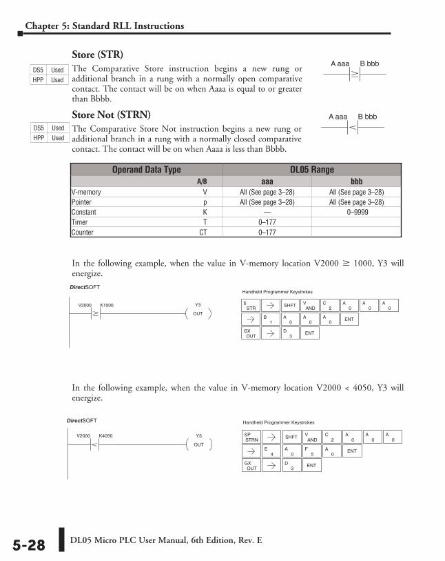
Store (STR)The Comparative Store instruction begins a new rung or additional branch in a rung with a normally open comparative contact. The contact will be on when Aaaa is equal to or greater than Bbbb.
Store Not (STRN)The Comparative Store Not instruction begins a new rung or additional branch in a rung with a normally closed comparative contact. The contact will be on when Aaaa is less than Bbbb.
In the following example, when the value in V-memory location V2000 M 1000, Y3 will energize.
In the following example, when the value in V-memory location V2000 < 4050, Y3 will energize.
A aaa B bbb
A aaa B bbb
Operand Data Type DL05 Range ⸠⸠⸠⸠⸠⸠⸠⸠⸠⸠⸠⸠⸠⸠⸠⸠⸠⸠⸠⸠⸠⸠⸠⸠⸠⸠⸠⸠⸠⸠⸠⸠⸠⸠⸠⸠⸠⸠⸠⸠⸠⸠⸠⸠⸠⸠⸠⸠⸠⸠⸠⸠⸠⸠⸠⸠⸠⸠⸠⸠⸠⸠⸠⸠⸠⸠⸠⸠⸠ A/B aaa bbbV-memory ⸠⸠⸠⸠⸠⸠⸠⸠⸠⸠⸠⸠⸠⸠⸠⸠⸠⸠⸠⸠⸠⸠⸠⸠⸠⸠⸠⸠⸠⸠⸠⸠⸠⸠⸠⸠⸠⸠⸠⸠⸠⸠⸠⸠⸠⸠⸠⸠⸠⸠⸠⸠⸠⸠⸠⸠⸠⸠V All (See page 3–28) All (See page 3–28)Pointer ⸠⸠⸠⸠⸠⸠⸠⸠⸠⸠⸠⸠⸠⸠⸠⸠⸠⸠⸠⸠⸠⸠⸠⸠⸠⸠⸠⸠⸠⸠⸠⸠⸠⸠⸠⸠⸠⸠⸠⸠⸠⸠⸠⸠⸠⸠⸠⸠⸠⸠⸠⸠⸠⸠⸠⸠⸠⸠⸠⸠⸠⸠⸠⸠⸠ p All (See page 3–28) All (See page 3–28)Constant ⸠⸠⸠⸠⸠⸠⸠⸠⸠⸠⸠⸠⸠⸠⸠⸠⸠⸠⸠⸠⸠⸠⸠⸠⸠⸠⸠⸠⸠⸠⸠⸠⸠⸠⸠⸠⸠⸠⸠⸠⸠⸠⸠⸠⸠⸠⸠⸠⸠⸠⸠⸠⸠⸠⸠⸠⸠⸠⸠⸠⸠K –– 0–9999Timer ⸠⸠⸠⸠⸠⸠⸠⸠⸠⸠⸠⸠⸠⸠⸠⸠⸠⸠⸠⸠⸠⸠⸠⸠⸠⸠⸠⸠⸠⸠⸠⸠⸠⸠⸠⸠⸠⸠⸠⸠⸠⸠⸠⸠⸠⸠⸠⸠⸠⸠⸠⸠⸠⸠⸠⸠⸠⸠⸠⸠⸠⸠⸠⸠⸠⸠ T 0–177Counter ⸠⸠⸠⸠⸠⸠⸠⸠⸠⸠⸠⸠⸠⸠⸠⸠⸠⸠⸠⸠⸠⸠⸠⸠⸠⸠⸠⸠⸠⸠⸠⸠⸠⸠⸠⸠⸠⸠⸠⸠⸠⸠⸠⸠⸠⸠⸠⸠⸠⸠⸠⸠⸠⸠⸠⸠⸠⸠⸠⸠⸠CT 0–177
ENT3
D
Y3
OUT
V2000 K1000
DirectSOFT32 Handheld Programmer Keystrokes
STR$
ENT
OUTGX
SHFTAND
V2
C0
A0
A0
A
1B
0A
0A
0A
ENT3
D
0A ENT
0A
4E
5F
Y3
OUT
V2000 K4050
DirectSOFT32 Handheld Programmer Keystrokes
OUTGX
STRNSP SHFT
ANDV
2C
0A
0A
0A
DS5 Used
HPP Used
DS5 Used
HPP Used
DirectSOFT
DirectSOFT
DL05 Micro PLC User Manual, 6th Edition, Rev. E 5-29
Chapter 5: Standard RLL Instructions
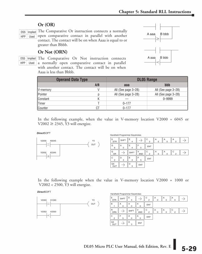
Or (OR)The Comparative Or instruction connects a normally open comparative contact in parallel with another contact. The contact will be on when Aaaa is equal to or greater than Bbbb.
Or Not (ORN)The Comparative Or Not instruction connects a normally open comparative contact in parallel with another contact. The contact will be on when Aaaa is less than Bbbb.
In the following example, when the value in V-memory location V2000 = 6045 or V2002 M 2345, Y3 will energize.
In the following example when the value in V-memory location V2000 = 1000 or V2002 < 2500, Y3 will energize.
A aaa B bbb
A aaa B bbb
2C
3D
4E
5F ENT
6G
0A
Y3
OUT
V2000 K6045
V2002 K2345
DirectSOFT32 Handheld Programmer Keystrokes
SHFT4
E2
C0
A0
A0
A
ENT
STR$
ORQ
OUTGX ENT
3D
4E
5F
SHFTAND
V2
C0
A0
A2
C
ENT3
D
2C
5F ENT
0A
0A
ENT1
B0
A0
A0
A
4E
Y3
OUT
V2000 K1000
V2002 K2500
DirectSOFT32 Handheld Programmer Keystrokes
STR$ SHFT
2C
0A
0A
0A
ORNR
OUTGX
SHFTAND
V2
C0
A0
A2
C
Operand Data Type DL05 Range ⸠⸠⸠⸠⸠⸠⸠⸠⸠⸠⸠⸠⸠⸠⸠⸠⸠⸠⸠⸠⸠⸠⸠⸠⸠⸠⸠⸠⸠⸠⸠⸠⸠⸠⸠⸠⸠⸠⸠⸠⸠⸠⸠⸠⸠⸠⸠⸠⸠⸠⸠⸠⸠⸠⸠⸠⸠⸠⸠⸠⸠⸠⸠⸠⸠⸠⸠⸠⸠ A/B aaa bbbV-memory ⸠⸠⸠⸠⸠⸠⸠⸠⸠⸠⸠⸠⸠⸠⸠⸠⸠⸠⸠⸠⸠⸠⸠⸠⸠⸠⸠⸠⸠⸠⸠⸠⸠⸠⸠⸠⸠⸠⸠⸠⸠⸠⸠⸠⸠⸠⸠⸠⸠⸠⸠⸠⸠⸠⸠⸠⸠⸠V All (See page 3–28) All (See page 3–28)Pointer ⸠⸠⸠⸠⸠⸠⸠⸠⸠⸠⸠⸠⸠⸠⸠⸠⸠⸠⸠⸠⸠⸠⸠⸠⸠⸠⸠⸠⸠⸠⸠⸠⸠⸠⸠⸠⸠⸠⸠⸠⸠⸠⸠⸠⸠⸠⸠⸠⸠⸠⸠⸠⸠⸠⸠⸠⸠⸠⸠⸠⸠⸠⸠⸠⸠ p All (See page 3–28) All (See page 3–28)Constant ⸠⸠⸠⸠⸠⸠⸠⸠⸠⸠⸠⸠⸠⸠⸠⸠⸠⸠⸠⸠⸠⸠⸠⸠⸠⸠⸠⸠⸠⸠⸠⸠⸠⸠⸠⸠⸠⸠⸠⸠⸠⸠⸠⸠⸠⸠⸠⸠⸠⸠⸠⸠⸠⸠⸠⸠⸠⸠⸠⸠⸠K –– 0–9999Timer ⸠⸠⸠⸠⸠⸠⸠⸠⸠⸠⸠⸠⸠⸠⸠⸠⸠⸠⸠⸠⸠⸠⸠⸠⸠⸠⸠⸠⸠⸠⸠⸠⸠⸠⸠⸠⸠⸠⸠⸠⸠⸠⸠⸠⸠⸠⸠⸠⸠⸠⸠⸠⸠⸠⸠⸠⸠⸠⸠⸠⸠⸠⸠⸠⸠⸠ T 0–177Counter ⸠⸠⸠⸠⸠⸠⸠⸠⸠⸠⸠⸠⸠⸠⸠⸠⸠⸠⸠⸠⸠⸠⸠⸠⸠⸠⸠⸠⸠⸠⸠⸠⸠⸠⸠⸠⸠⸠⸠⸠⸠⸠⸠⸠⸠⸠⸠⸠⸠⸠⸠⸠⸠⸠⸠⸠⸠⸠⸠⸠⸠CT 0–177
DS5 Implied
HPP Used
DS5 Implied
HPP Used
DirectSOFT
DirectSOFT
DL05 Micro PLC User Manual, 6th Edition, Rev. E5-30
Chapter 5: Standard RLL Instructions
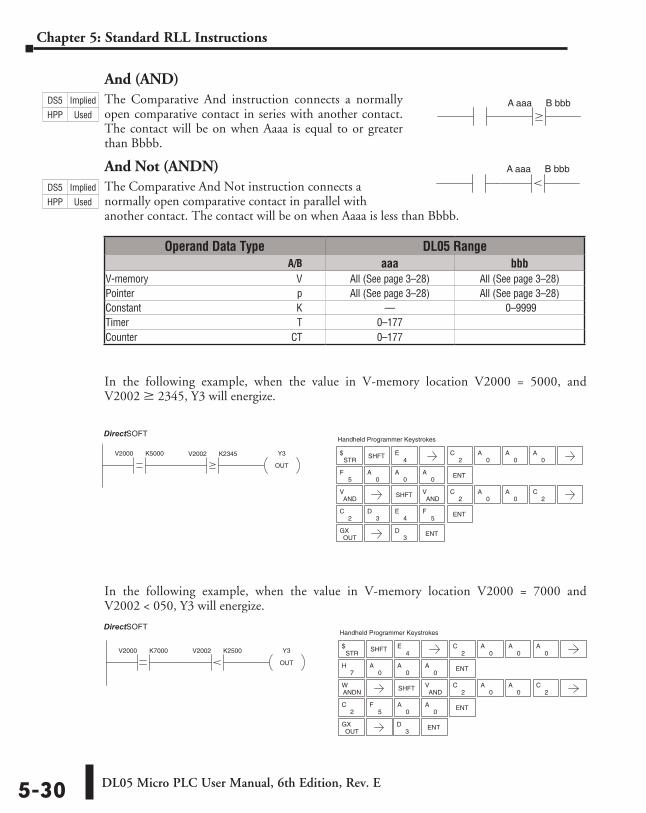
And (AND)The Comparative And instruction connects a normally open comparative contact in series with another contact. The contact will be on when Aaaa is equal to or greater than Bbbb.
And Not (ANDN)The Comparative And Not instruction connects a normally open comparative contact in parallel with another contact. The contact will be on when Aaaa is less than Bbbb.
In the following example, when the value in V-memory location V2000 = 5000, and V2002 M 2345, Y3 will energize.
In the following example, when the value in V-memory location V2000 = 7000 and V2002 < 050, Y3 will energize.
A aaa B bbb
A aaa B bbb
ENT3
D
2C
3D
4E
5F ENT
ENT0
A0
A5
F0
A
2CY3
OUT
V2000 K5000 V2002 K2345
DirectSOFT32 Handheld Programmer Keystrokes
STR$ SHFT
4E
0A
0A
0A
ANDV
OUTGX
SHFTAND
V2
C0
A0
A2
C
2C
5F ENT
0A
0A
7H ENT
0A
0A
0A
2C
Y3
OUT
V2000 K7000 V2002 K2500
DirectSOFT32 Handheld Programmer Keystrokes
STR$ SHFT
4E
2C
0A
0A
0A
ANDNW
OUTGX ENT
3D
SHFTAND
V2
C0
A0
A
Operand Data Type DL05 Range ⸠⸠⸠⸠⸠⸠⸠⸠⸠⸠⸠⸠⸠⸠⸠⸠⸠⸠⸠⸠⸠⸠⸠⸠⸠⸠⸠⸠⸠⸠⸠⸠⸠⸠⸠⸠⸠⸠⸠⸠⸠⸠⸠⸠⸠⸠⸠⸠⸠⸠⸠⸠⸠⸠⸠⸠⸠⸠⸠⸠⸠⸠⸠⸠⸠⸠⸠⸠⸠ A/B aaa bbbV-memory ⸠⸠⸠⸠⸠⸠⸠⸠⸠⸠⸠⸠⸠⸠⸠⸠⸠⸠⸠⸠⸠⸠⸠⸠⸠⸠⸠⸠⸠⸠⸠⸠⸠⸠⸠⸠⸠⸠⸠⸠⸠⸠⸠⸠⸠⸠⸠⸠⸠⸠⸠⸠⸠⸠⸠⸠⸠⸠V All (See page 3–28) All (See page 3–28)Pointer ⸠⸠⸠⸠⸠⸠⸠⸠⸠⸠⸠⸠⸠⸠⸠⸠⸠⸠⸠⸠⸠⸠⸠⸠⸠⸠⸠⸠⸠⸠⸠⸠⸠⸠⸠⸠⸠⸠⸠⸠⸠⸠⸠⸠⸠⸠⸠⸠⸠⸠⸠⸠⸠⸠⸠⸠⸠⸠⸠⸠⸠⸠⸠⸠⸠ p All (See page 3–28) All (See page 3–28)Constant ⸠⸠⸠⸠⸠⸠⸠⸠⸠⸠⸠⸠⸠⸠⸠⸠⸠⸠⸠⸠⸠⸠⸠⸠⸠⸠⸠⸠⸠⸠⸠⸠⸠⸠⸠⸠⸠⸠⸠⸠⸠⸠⸠⸠⸠⸠⸠⸠⸠⸠⸠⸠⸠⸠⸠⸠⸠⸠⸠⸠⸠K –– 0–9999Timer ⸠⸠⸠⸠⸠⸠⸠⸠⸠⸠⸠⸠⸠⸠⸠⸠⸠⸠⸠⸠⸠⸠⸠⸠⸠⸠⸠⸠⸠⸠⸠⸠⸠⸠⸠⸠⸠⸠⸠⸠⸠⸠⸠⸠⸠⸠⸠⸠⸠⸠⸠⸠⸠⸠⸠⸠⸠⸠⸠⸠⸠⸠⸠⸠⸠⸠ T 0–177Counter ⸠⸠⸠⸠⸠⸠⸠⸠⸠⸠⸠⸠⸠⸠⸠⸠⸠⸠⸠⸠⸠⸠⸠⸠⸠⸠⸠⸠⸠⸠⸠⸠⸠⸠⸠⸠⸠⸠⸠⸠⸠⸠⸠⸠⸠⸠⸠⸠⸠⸠⸠⸠⸠⸠⸠⸠⸠⸠⸠⸠⸠CT 0–177
DS5 Implied
HPP Used
DS5 Implied
HPP Used
DirectSOFT
DirectSOFT
DL05 Micro PLC User Manual, 6th Edition, Rev. E 5-31
Chapter 5: Standard RLL Instructions
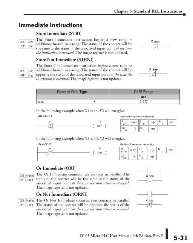
Immediate InstructionsStore Immediate (STRI)The Store Immediate instruction begins a new rung or additional branch in a rung. The status of the contact will be the same as the status of the associated input point at the time the instruction is executed. The image register is not updated.
Store Not Immediate (STRNI)The Store Not Immediate instruction begins a new rung or additional branch in a rung. The status of the contact will be opposite the status of the associated input point at the time the instruction is executed. The image register is not updated.
In the following example when X1 is on, Y2 will energize.
In the following example when X1 is off, Y2 will energize.
Or Immediate (ORI)The Or Immediate connects two contacts in parallel. The status of the contact will be the same as the status of the associated input point at the time the instruction is executed. The image register is not updated.
Or Not Immediate (ORNI)The Or Not Immediate connects two contacts in parallel. The status of the contact will be opposite the status of the associated input point at the time the instruction is executed. The image register is not updated.
aaaX
aaaX
ENT2
C
1B ENTX1 Y2
OUT
Handheld Programmer KeystrokesDirectSOFT32
STR$ SHFT
8I
OUTGX
ENT2
C
1B ENT
X1 Y2
OUT
Handheld Programmer KeystrokesDirectSOFT32
STRNSP SHFT
8I
OUTGX
aaaX
aaaX
Operand Data Type DL05 Rangeaaa
Inputs ⸠⸠⸠⸠⸠⸠⸠⸠⸠⸠⸠⸠⸠⸠⸠⸠⸠⸠⸠⸠⸠⸠⸠⸠⸠⸠⸠⸠⸠⸠⸠⸠⸠⸠⸠⸠⸠⸠⸠⸠⸠⸠⸠⸠⸠⸠⸠⸠⸠⸠⸠⸠⸠⸠⸠⸠⸠⸠⸠⸠⸠⸠⸠⸠⸠X 0–377
DS5 Used
HPP Used
DS5 Used
HPP Used
DS5 Implied
HPP Used
DS5 Implied
HPP Used
DirectSOFT
DirectSOFT
DL05 Micro PLC User Manual, 6th Edition, Rev. E5-32
Chapter 5: Standard RLL Instructions
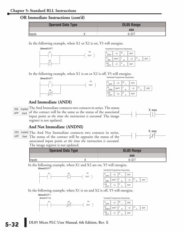
OR Immediate Instructions (cont’d)
In the following example, when X1 or X2 is on, Y5 will energize.
In the following example, when X1 is on or X2 is off, Y5 will energize.
And Immediate (ANDI)The And Immediate connects two contacts in series. The status of the contact will be the same as the status of the associated input point at the time the instruction is executed. The image register is not updated.
And Not Immediate (ANDNI)The And Not Immediate connects two contacts in series. The status of the contact will be opposite the status of the associated input point at the time the instruction is executed. The image register is not updated.
1B ENT
ENT2
C
ENT5
F
X1
X2
Y5
OUT
Handheld Programmer KeystrokesDirectSOFT32
STR$
ORQ SHFT
8I
OUTGX
ENT5
F
ENT2
C
1B ENT
X1
X2
Y5
OUT
Handheld Programmer KeystrokesDirectSOFT32
STR$
SHFT8
IORN
R
OUTGX
aaaX
aaaX
OUTGX
X1 X2 Y5
OUT
Handheld Programmer KeystrokesDirectSOFT32
STR$
1B ENT
ANDV SHFT
8I ENT
2C
ENT5
F
X1 X2 Y5
OUT
Handheld Programmer KeystrokesDirectSOFT32
STR$
ANDNW SHFT
8I
OUTGX
1B ENT
ENT2
C
ENT5
F
Operand Data Type DL05 Rangeaaa
Inputs ⸠⸠⸠⸠⸠⸠⸠⸠⸠⸠⸠⸠⸠⸠⸠⸠⸠⸠⸠⸠⸠⸠⸠⸠⸠⸠⸠⸠⸠⸠⸠⸠⸠⸠⸠⸠⸠⸠⸠⸠⸠⸠⸠⸠⸠⸠⸠⸠⸠⸠⸠⸠⸠⸠⸠⸠⸠⸠⸠⸠⸠⸠⸠⸠⸠X 0–377
Operand Data Type DL05 Rangeaaa
Inputs ⸠⸠⸠⸠⸠⸠⸠⸠⸠⸠⸠⸠⸠⸠⸠⸠⸠⸠⸠⸠⸠⸠⸠⸠⸠⸠⸠⸠⸠⸠⸠⸠⸠⸠⸠⸠⸠⸠⸠⸠⸠⸠⸠⸠⸠⸠⸠⸠⸠⸠⸠⸠⸠⸠⸠⸠⸠⸠⸠⸠⸠⸠⸠⸠⸠X 0–377
In the following example, when X1 is on and X2 is off, Y5 will energize.
In the following example, when X1 and X2 are on, Y5 will energize.
DS5 Implied
HPP Used
DS5 Implied
HPP Used
DirectSOFT
DirectSOFT
DirectSOFT
DirectSOFT
DL05 Micro PLC User Manual, 6th Edition, Rev. E 5-33
Chapter 5: Standard RLL Instructions
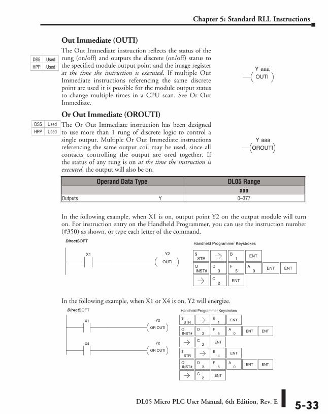
Out Immediate (OUTI)The Out Immediate instruction reflects the status of the rung (on/off) and outputs the discrete (on/off) status to the specified module output point and the image register at the time the instruction is executed. If multiple Out Immediate instructions referencing the same discrete point are used it is possible for the module output status to change multiple times in a CPU scan. See Or Out Immediate.
Or Out Immediate (OROUTI)The Or Out Immediate instruction has been designed to use more than 1 rung of discrete logic to control a single output. Multiple Or Out Immediate instructions referencing the same output coil may be used, since all contacts controlling the output are ored together. If the status of any rung is on at the time the instruction is executed, the output will also be on.
In the following example, when X1 is on, output point Y2 on the output module will turn on. For instruction entry on the Handheld Programmer, you can use the instruction number (#350) as shown, or type each letter of the command.
In the following example, when X1 or X4 is on, Y2 will energize.
Y aaa
OUTI
OROUTI
Y aaa
1B ENTX1 Y2
OUTI
DirectSOFT32 Handheld Programmer Keystrokes
STR$
INST#O
5F
3D
0A ENT ENT
2C ENT
STR$
X1
X4
Y2
OR OUTI
Y2
OR OUTI
DirectSOFT32 Handheld Programmer Keystrokes
STR$
1B ENT
ENT4
E
INST#O
5F
3D
0A ENT ENT
2C ENT
INST#O
5F
3D
0A ENT ENT
2C ENT
Operand Data Type DL05 Rangeaaa
Outputs ⸠⸠⸠⸠⸠⸠⸠⸠⸠⸠⸠⸠⸠⸠⸠⸠⸠⸠⸠⸠⸠⸠⸠⸠⸠⸠⸠⸠⸠⸠⸠⸠⸠⸠⸠⸠⸠⸠⸠⸠⸠⸠⸠⸠⸠⸠⸠⸠⸠⸠⸠⸠⸠⸠⸠⸠⸠⸠⸠⸠⸠⸠⸠Y 0–377
DS5 Used
HPP Used
DS5 Used
HPP Used
DirectSOFT
DirectSOFT
DL05 Micro PLC User Manual, 6th Edition, Rev. E5-34
Chapter 5: Standard RLL Instructions
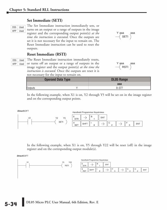
Set Immediate (SETI)The Set Immediate instruction immediately sets, or turns on an output or a range of outputs in the image register and the corresponding output point(s) at the time the instruction is executed. Once the outputs are set it is not necessary for the input to remain on. The Reset Immediate instruction can be used to reset the outputs.
Reset Immediate (RSTI)The Reset Immediate instruction immediately resets, or turns off an output or a range of outputs in the image register and the output point(s) at the time the instruction is executed. Once the outputs are reset it is not necessary for the input to remain on.
In the following example, when X1 is on, Y2 through Y5 will be set on in the image register and on the corresponding output points.
In the following example, when X1 is on, Y5 through Y22 will be reset (off) in the image register and on the corresponding output module(s).
aaaY aaaSETI
aaaY aaaRSTI
1B ENTX1 Y2
SETI
Y5
DirectSOFT32 Handheld Programmer Keystrokes
STR$
SETX SHFT
8I ENT
2C
5F
1B ENT
X1 Y5
RSTI
Y22
DirectSOFT32
Handheld Programmer Keystrokes
STR$
SHFT8
I5
F2
C2
C ENTRST
S
Operand Data Type DL05 Rangeaaa
Outputs ⸠⸠⸠⸠⸠⸠⸠⸠⸠⸠⸠⸠⸠⸠⸠⸠⸠⸠⸠⸠⸠⸠⸠⸠⸠⸠⸠⸠⸠⸠⸠⸠⸠⸠⸠⸠⸠⸠⸠⸠⸠⸠⸠⸠⸠⸠⸠⸠⸠⸠⸠⸠⸠⸠⸠⸠⸠⸠⸠⸠⸠⸠⸠Y 0–377
DS5 Used
HPP Used
DS5 Used
HPP Used
DirectSOFT
DirectSOFT
DL05 Micro PLC User Manual, 6th Edition, Rev. E 5-35
Chapter 5: Standard RLL Instructions
Timer, Counter and Shift Register InstructionsUsing Timers
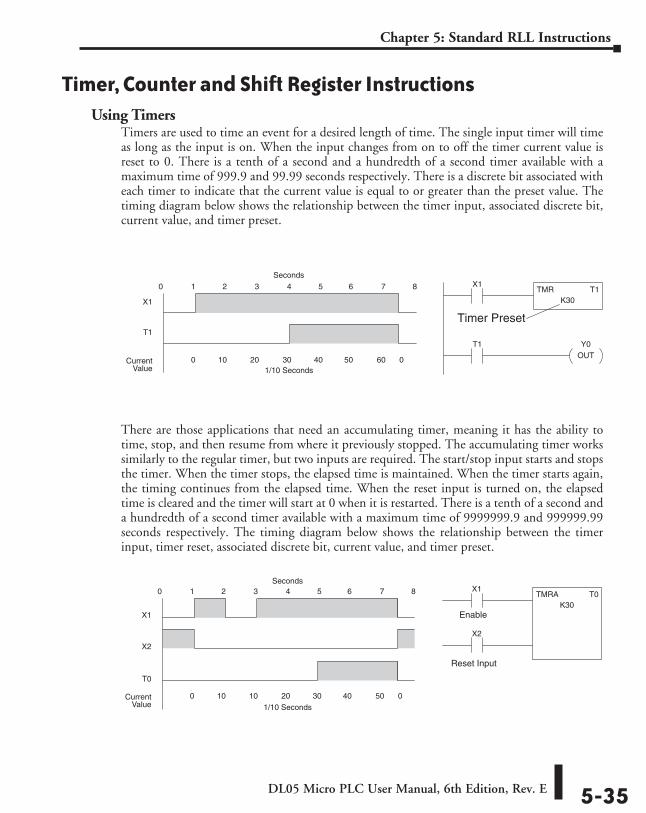
Timers are used to time an event for a desired length of time. The single input timer will time as long as the input is on. When the input changes from on to off the timer current value is reset to 0. There is a tenth of a second and a hundredth of a second timer available with a maximum time of 999.9 and 99.99 seconds respectively. There is a discrete bit associated with each timer to indicate that the current value is equal to or greater than the preset value. The timing diagram below shows the relationship between the timer input, associated discrete bit, current value, and timer preset.
There are those applications that need an accumulating timer, meaning it has the ability to time, stop, and then resume from where it previously stopped. The accumulating timer works similarly to the regular timer, but two inputs are required. The start/stop input starts and stops the timer. When the timer stops, the elapsed time is maintained. When the timer starts again, the timing continues from the elapsed time. When the reset input is turned on, the elapsed time is cleared and the timer will start at 0 when it is restarted. There is a tenth of a second and a hundredth of a second timer available with a maximum time of 9999999.9 and 999999.99 seconds respectively. The timing diagram below shows the relationship between the timer input, timer reset, associated discrete bit, current value, and timer preset.
X1
X1
T0
1 2 3 4 5 6 7 80
0 10 10 20 30 40 50 0CurrentValue
TMRA T0K30
X2
X2
Reset Input
Enable
Seconds
1/10 Seconds
TMR T1K30
X1
X1
T1
1 2 3 4 5 6 7 80
0 10 20 30 40 50 60 0CurrentValue
T1 Y0OUT
Seconds
1/10 Seconds
Timer Preset
DL05 Micro PLC User Manual, 6th Edition, Rev. E5-36
Chapter 5: Standard RLL Instructions
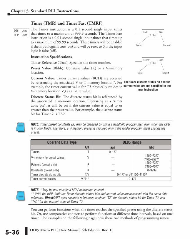
Timer (TMR) and Timer Fast (TMRF)The Timer instruction is a 0.1 second single input timer that times to a maximum of 999.9 seconds. The Timer Fast instruction is a 0.01 second single input timer that times up to a maximum of 99.99 seconds. These timers will be enabled if the input logic is true (on) and will be reset to 0 if the input logic is false (off).
Instruction Specifications
Timer Reference (Taaa): Specifies the timer number.
Preset Value (Bbbb): Constant value (K) or a V-memory location.
Current Value: Timer current values (BCD) are accessed by referencing the associated V or T memory location*. For example, the timer current value for T3 physically resides in V-memory location V3 as a BCD value.
Discrete Status Bit: The discrete status bit is referenced by the associated T memory location. Operating as a “timer done bit”, it will be on if the current value is equal to or greater than the preset value. For example, the discrete status bit for Timer 2 is TA2.
NOTE: Timer preset constants (K) may be changed by using a handheld programmer, even when the CPU is in Run Mode. Therefore, a V-memory preset is required only if the ladder program must change the preset.
NOTE: * May be non-volatile if MOV instruction is used. ** With the HPP, both the Timer discrete status bits and current value are accessed with the same data reference. DirectSOFT uses separate references, such as “T2” for discrete status bit for Timer T2, and “TA2” for the current value of Timer T2.
You can perform functions when the timer reaches the specified preset using the discrete status bit. Or, use comparative contacts to perform functions at different time intervals, based on one timer. The examples on the following page show these two methods of programming timers.
T aaa
aaaTTMRB bbb
Preset Timer #
TMRFB bbb
Preset Timer #
Operand Data Type DL05 Range ⸠⸠⸠⸠⸠⸠⸠⸠⸠⸠⸠⸠⸠⸠⸠⸠⸠⸠⸠⸠⸠⸠⸠⸠⸠⸠⸠⸠⸠⸠⸠⸠⸠⸠⸠⸠⸠⸠⸠⸠⸠⸠⸠⸠⸠⸠⸠⸠⸠⸠⸠⸠⸠⸠⸠⸠⸠⸠⸠⸠⸠⸠⸠⸠⸠⸠⸠⸠⸠ A/B aaa bbbTimers ⸠⸠⸠⸠⸠⸠⸠⸠⸠⸠⸠⸠⸠⸠⸠⸠⸠⸠⸠⸠⸠⸠⸠⸠⸠⸠⸠⸠⸠⸠⸠⸠⸠⸠⸠⸠⸠⸠⸠⸠⸠⸠⸠⸠⸠⸠⸠⸠⸠⸠⸠⸠⸠⸠⸠⸠⸠⸠⸠⸠⸠⸠⸠⸠ T 0–177 ––
V-memory for preset values ⸠⸠⸠⸠⸠⸠⸠⸠⸠⸠⸠⸠⸠⸠⸠⸠⸠⸠⸠⸠⸠⸠⸠⸠⸠⸠⸠⸠⸠⸠V –– 1200–7377 7400–7577*
Pointers (preset only) ⸠⸠⸠⸠⸠⸠⸠⸠⸠⸠⸠⸠⸠⸠⸠⸠⸠⸠⸠⸠⸠⸠⸠⸠⸠⸠⸠⸠⸠⸠⸠⸠⸠⸠⸠⸠⸠⸠⸠⸠P –– 1200–7377 7400–7577
Constants (preset only) ⸠⸠⸠⸠⸠⸠⸠⸠⸠⸠⸠⸠⸠⸠⸠⸠⸠⸠⸠⸠⸠⸠⸠⸠⸠⸠⸠⸠⸠⸠⸠⸠⸠⸠⸠⸠⸠K –– 0–9999Timer discrete status bits ⸠⸠⸠⸠⸠⸠⸠⸠⸠⸠⸠⸠⸠⸠⸠⸠⸠⸠⸠⸠⸠⸠⸠⸠⸠⸠⸠⸠⸠⸠⸠T/V 0–177 or V41100–41107Timer current values ⸠⸠⸠⸠⸠⸠⸠⸠⸠⸠⸠⸠⸠⸠⸠⸠⸠⸠⸠⸠⸠⸠⸠⸠⸠⸠⸠⸠⸠⸠⸠⸠⸠ V /T** 0–177
The timer discrete status bit and the current value are not specified in the
timer instruction
DS5 Used
HPP Used
DL05 Micro PLC User Manual, 6th Edition, Rev. E 5-37
Chapter 5: Standard RLL Instructions
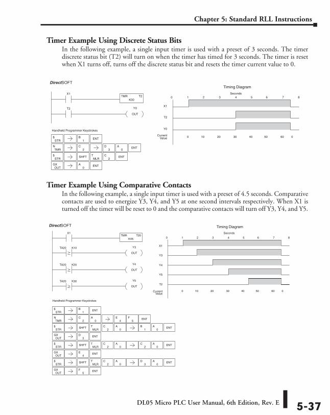
Timer Example Using Discrete Status BitsIn the following example, a single input timer is used with a preset of 3 seconds. The timer discrete status bit (T2) will turn on when the timer has timed for 3 seconds. The timer is reset when X1 turns off, turns off the discrete status bit and resets the timer current value to 0.
Timer Example Using Comparative ContactsIn the following example, a single input timer is used with a preset of 4.5 seconds. Comparative contacts are used to energize Y3, Y4, and Y5 at one second intervals respectively. When X1 is turned off the timer will be reset to 0 and the comparative contacts will turn off Y3, Y4, and Y5.
STR$
TMRN
2C
STR$ SHFT
MLRT
2C ENT
OUTGX
Handheld Programmer Keystrokes
X1TMR T2
K30
T2 Y0
OUT
X1
T2
1 2 3 4 5 6 7 80
0 10 20 30 40 50 60 0CurrentValue
Y0
Timing DiagramDirect SOFT32
Seconds
1B ENT
3D
0A ENT
ENT0
A
1B ENT
Handheld Programmer Keystrokes
X1TMR T20
K45
TA20 K10
TA20 K20
TA20 K30
Y4
OUT
Y3
OUT
Y5
OUT
X1
Y3
1 2 3 4 5 6 7 80
0 10 20 30 40 50 60 0CurrentValue
Y4
Timing Diagram
Y5
T2
Direct SOFT32
Seconds
STR$
TMRN
2C ENT
0A
4E
5F
STR$ SHFT
MLRT
2C
0A
1B ENT
OUTGX ENT
3D
STR$ SHFT
MLRT
2C
0A ENT
OUTGX ENT
2C
4E
STR$ SHFT
MLRT
2C
0A ENT
OUTGX ENT
3D
5F
0A
0A
0A
DirectSOFT
DirectSOFT
DL05 Micro PLC User Manual, 6th Edition, Rev. E5-38
Chapter 5: Standard RLL Instructions
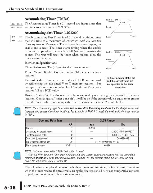
Accumulating Timer (TMRA)The Accumulating Timer is a 0.1 second two input timer that will time to a maximum of 9999999.9.
Accumulating Fast Timer (TMRAF)The Accumulating Fast Timer is a 0.01 second two-input timer that will time to a maximum of 99999.99. Each one uses two timer registers in V-memory. These timers have two inputs, an enable and a reset. The timer starts timing when the enable is on and stops when the enable is off (without resetting the count). The reset will reset the timer when on and allow the timer to time when off.
Instruction Specifications
Timer Reference (Taaa): Specifies the timer number.
Preset Value (Bbbb): Constant value (K) or a V-memory location.
Current Value: Timer current values (BCD) are accessed by referencing the associated V or T memory location*. For example, the timer current value for T3 resides in V-memory location V3 as a BCD value.
Discrete Status Bit: The discrete status bit is accessed by referencing the associated T memory location. Operating as a “timer done bit”, it will be on if the current value is equal to or greater than the preset value. For example the discrete status bit for timer 2 would be T2.
NOTE: The accumulating type timer uses two consecutive V-memory locations for the 8-digit value, and therefore two consecutive timer locations. For example, if TMR 1 is used, the next available timer number is TMR 3.
NOTE: * May be non-volatile if MOV instruction is used. ** With the HPP, both the Timer discrete status bits and current value are accessed with the same data reference. DirectSOFT uses separate references, such as “T2” for discrete status bit for Timer T2, and “TA2” for the current value of Timer T2.
The following examples show two methods of programming timers. One performs functions when the timer reaches the preset value using the discrete status bit, or use comparative contacts to perform functions at different time intervals.
T aaa
T aaaTMRAB bbb
Enable
Reset
Preset Timer #
TMRAFB bbb
Enable
Reset
Preset Timer #
Operand Data Type DL05 Range ⸠⸠⸠⸠⸠⸠⸠⸠⸠⸠⸠⸠⸠⸠⸠⸠⸠⸠⸠⸠⸠⸠⸠⸠⸠⸠⸠⸠⸠⸠⸠⸠⸠⸠⸠⸠⸠⸠⸠⸠⸠⸠⸠⸠⸠⸠⸠⸠⸠⸠⸠⸠⸠⸠⸠⸠⸠⸠⸠⸠⸠⸠⸠⸠⸠⸠⸠⸠⸠ A/B aaa bbbTimers ⸠⸠⸠⸠⸠⸠⸠⸠⸠⸠⸠⸠⸠⸠⸠⸠⸠⸠⸠⸠⸠⸠⸠⸠⸠⸠⸠⸠⸠⸠⸠⸠⸠⸠⸠⸠⸠⸠⸠⸠⸠⸠⸠⸠⸠⸠⸠⸠⸠⸠⸠⸠⸠⸠⸠⸠⸠⸠⸠⸠⸠⸠⸠⸠ T 0–176 ––V-memory for preset values ⸠⸠⸠⸠⸠⸠⸠⸠⸠⸠⸠⸠⸠⸠⸠⸠⸠⸠⸠⸠⸠⸠⸠⸠⸠⸠⸠⸠⸠⸠V –– 1200–7377/7400–7577*Pointers (preset only) ⸠⸠⸠⸠⸠⸠⸠⸠⸠⸠⸠⸠⸠⸠⸠⸠⸠⸠⸠⸠⸠⸠⸠⸠⸠⸠⸠⸠⸠⸠⸠⸠⸠⸠⸠⸠⸠⸠⸠⸠P –– 1200–7377/7400–7577Constants (preset only) ⸠⸠⸠⸠⸠⸠⸠⸠⸠⸠⸠⸠⸠⸠⸠⸠⸠⸠⸠⸠⸠⸠⸠⸠⸠⸠⸠⸠⸠⸠⸠⸠⸠⸠⸠⸠⸠K –– 0–99999999Timer discrete status bits ⸠⸠⸠⸠⸠⸠⸠⸠⸠⸠⸠⸠⸠⸠⸠⸠⸠⸠⸠⸠⸠⸠⸠⸠⸠⸠⸠⸠⸠⸠⸠T/V 0–176 or V41100–41107Timer current values ⸠⸠⸠⸠⸠⸠⸠⸠⸠⸠⸠⸠⸠⸠⸠⸠⸠⸠⸠⸠⸠⸠⸠⸠⸠⸠⸠⸠⸠⸠⸠⸠⸠ V /T** 0–176
The timer discrete status bit and the current value are not specified in the timer
instruction
DS5 Used
HPP Used
DS5 Used
HPP Used
DL05 Micro PLC User Manual, 6th Edition, Rev. E 5-39
Chapter 5: Standard RLL Instructions
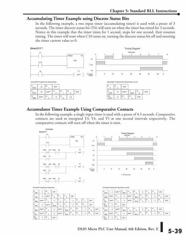
Accumulating Timer Example using Discrete Status BitsIn the following example, a two input timer (accumulating timer) is used with a preset of 3 seconds. The timer discrete status bit (T6) will turn on when the timer has timed for 3 seconds. Notice in this example that the timer times for 1 second, stops for one second, then resumes timing. The timer will reset when C10 turns on, turning the discrete status bit off and resetting the timer current value to 0.
Accumulator Timer Example Using Comparative ContactsIn the following example, a single input timer is used with a preset of 4.5 seconds. Comparative contacts are used to energized Y3, Y4, and Y5 at one second intervals respectively. The comparative contacts will turn off when the timer is reset.
Handheld Programmer Keystrokes
X1
T6
TMRA T6
K30C10
Y7
OUT
X1
C10
1 2 3 4 5 6 7 80
0 10 10 20 30 40 50 0CurrentValue
T6
Timing DiagramDirect SOFT32
Seconds
Handheld Programmer Keystrokes (cont)
STR$
STR$ SHFT ENT
2C
1B
0A
TMRN SHFT
0A
3D
0A ENT
STR$ SHFT
MLRT ENT
OUTGX ENT
0A
6G
1B
1B ENT
6G
Handheld Programmer Keystrokes
TA20 K10
TA21 K1
TA20 K20
Y3
OUT
Y4
OUT
X1
TMRA T20
K45C10
X1
C10
1 2 3 4 5 6 7 80
0 10 10 20 30 40 50 0CurrentValue
Timing Diagram
Y3
Y4
Y5
T20
DirectSOFT
Handheld Programmer Keystrokes (cont’d)
Seconds
ANDV SHFT4
EMLR
T
OUTGX ENT
1B
4E
STR$ SHFT
MLRT
2C
0A
OUTGX ENT
5F
STR$
1B ENT
ENT4
E5
F
STR$ SHFT
MLRT
2C
0A
1B ENT
OUTGX ENT
3D
STR$ SHFT ENT
2C
1B
0A
2C
0A
TMRN SHFT
0A
0A
0A
Contacts
TA21 K1
TA20 K30 Y5
OUT
TA21 K0
TA21 K0
TA21 K1
ORQ SHFT4
EMLR
T1
B1
B
ENT
ENT
SHFT
SHFT
2C
2C
STR$ SHFT
MLRT
2C
0A
ANDV SHFT4
EMLR
T1
B0
A
ORQ SHFT4
EMLR
T1
B1
B
ENT
ENT
SHFT
SHFT
2C
2C
ENT2
C0
A
ENT3
D0
A
ANDV SHFT4
EMLR
T1
B1
B ENTSHFT2
C
DirectSOFT
1/10 Seconds
DL05 Micro PLC User Manual, 6th Edition, Rev. E5-40
Chapter 5: Standard RLL Instructions
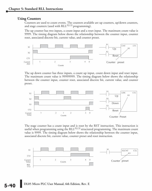
Using CountersCounters are used to count events. The counters available are up counters, up/down counters, and stage counters (used with RLLPLUS programming).
The up counter has two inputs, a count input and a reset input. The maximum count value is 9999. The timing diagram below shows the relationship between the counter input, counter reset, associated discrete bit, current value, and counter preset.
The up down counter has three inputs, a count up input, count down input and reset input. The maximum count value is 99999999. The timing diagram below shows the relationship between the counter input, counter reset, associated discrete bit, current value, and counter preset.
The stage counter has a count input and is reset by the RST instruction. This instruction is useful when programming using the RLLPLUS structured programming. The maximum count value is 9999. The timing diagram below shows the relationship between the counter input, associated discrete bit, current value, counter preset and reset instruction.
X1X1
CT1
1 2 3 4 0Currentalue
CNT CT1K3
X2X2
Counter preset
Up
Reset
Counts
X1X1
CT2
1 2 3 4 0CurrentValue
SGCNT CT2K3
RSTCT2
Counts Counter preset
X1X1
CT2
1 2 1 2 3 0CurrentValue
X2X2
UDC CT2K3
X3X3
Counter Preset
Up
Down
Reset
Counts
DL05 Micro PLC User Manual, 6th Edition, Rev. E 5-41
Chapter 5: Standard RLL Instructions
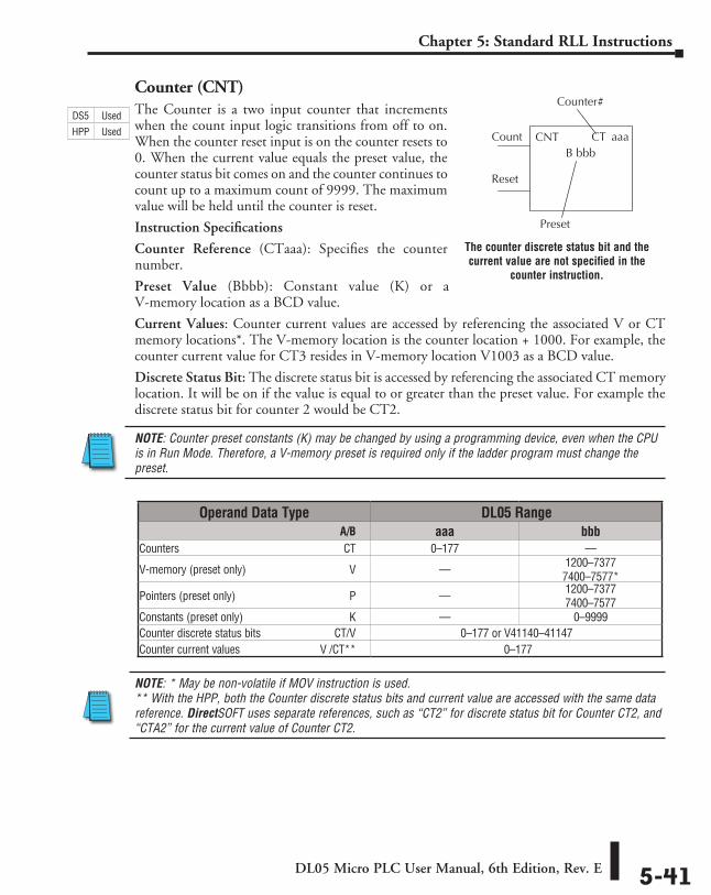
Counter (CNT)The Counter is a two input counter that increments when the count input logic transitions from off to on. When the counter reset input is on the counter resets to 0. When the current value equals the preset value, the counter status bit comes on and the counter continues to count up to a maximum count of 9999. The maximum value will be held until the counter is reset.
Instruction Specifications
Counter Reference (CTaaa): Specifies the counter number.
Preset Value (Bbbb): Constant value (K) or a V-memory location as a BCD value.
Current Values: Counter current values are accessed by referencing the associated V or CT memory locations*. The V-memory location is the counter location + 1000. For example, the counter current value for CT3 resides in V-memory location V1003 as a BCD value.
Discrete Status Bit: The discrete status bit is accessed by referencing the associated CT memory location. It will be on if the value is equal to or greater than the preset value. For example the discrete status bit for counter 2 would be CT2.
NOTE: Counter preset constants (K) may be changed by using a programming device, even when the CPU is in Run Mode. Therefore, a V-memory preset is required only if the ladder program must change the preset.
NOTE: * May be non-volatile if MOV instruction is used. ** With the HPP, both the Counter discrete status bits and current value are accessed with the same data reference. DirectSOFT uses separate references, such as “CT2” for discrete status bit for Counter CT2, and “CTA2” for the current value of Counter CT2.
CT aaaCNTB bbb
Count
Reset
Counter #
Preset
Operand Data Type DL05 Range ⸠⸠⸠⸠⸠⸠⸠⸠⸠⸠⸠⸠⸠⸠⸠⸠⸠⸠⸠⸠⸠⸠⸠⸠⸠⸠⸠⸠⸠⸠⸠⸠⸠⸠⸠⸠⸠⸠⸠⸠⸠⸠⸠⸠⸠⸠⸠⸠⸠⸠⸠⸠⸠⸠⸠⸠⸠⸠⸠⸠⸠⸠⸠⸠⸠⸠⸠⸠⸠ A/B aaa bbbCounters ⸠⸠⸠⸠⸠⸠⸠⸠⸠⸠⸠⸠⸠⸠⸠⸠⸠⸠⸠⸠⸠⸠⸠⸠⸠⸠⸠⸠⸠⸠⸠⸠⸠⸠⸠⸠⸠⸠⸠⸠⸠⸠⸠⸠⸠⸠⸠⸠⸠⸠⸠⸠⸠⸠⸠⸠⸠⸠⸠CT 0–177 ––
V-memory (preset only) ⸠⸠⸠⸠⸠⸠⸠⸠⸠⸠⸠⸠⸠⸠⸠⸠⸠⸠⸠⸠⸠⸠⸠⸠⸠⸠⸠⸠⸠⸠⸠⸠⸠⸠⸠⸠V –– 1200–7377 7400–7577*
Pointers (preset only) ⸠⸠⸠⸠⸠⸠⸠⸠⸠⸠⸠⸠⸠⸠⸠⸠⸠⸠⸠⸠⸠⸠⸠⸠⸠⸠⸠⸠⸠⸠⸠⸠⸠⸠⸠⸠⸠⸠⸠⸠P –– 1200–7377 7400–7577
Constants (preset only) ⸠⸠⸠⸠⸠⸠⸠⸠⸠⸠⸠⸠⸠⸠⸠⸠⸠⸠⸠⸠⸠⸠⸠⸠⸠⸠⸠⸠⸠⸠⸠⸠⸠⸠⸠⸠⸠K –– 0–9999Counter discrete status bits ⸠⸠⸠⸠⸠⸠⸠⸠⸠⸠⸠⸠⸠⸠⸠⸠⸠⸠⸠⸠⸠⸠⸠⸠⸠ CT/V 0–177 or V41140–41147Counter current values ⸠⸠⸠⸠⸠⸠⸠⸠⸠⸠⸠⸠⸠⸠⸠⸠⸠⸠⸠⸠⸠⸠⸠⸠⸠⸠⸠V /CT** 0–177
The counter discrete status bit and the current value are not specified in the
counter instruction.
DS5 Used
HPP Used
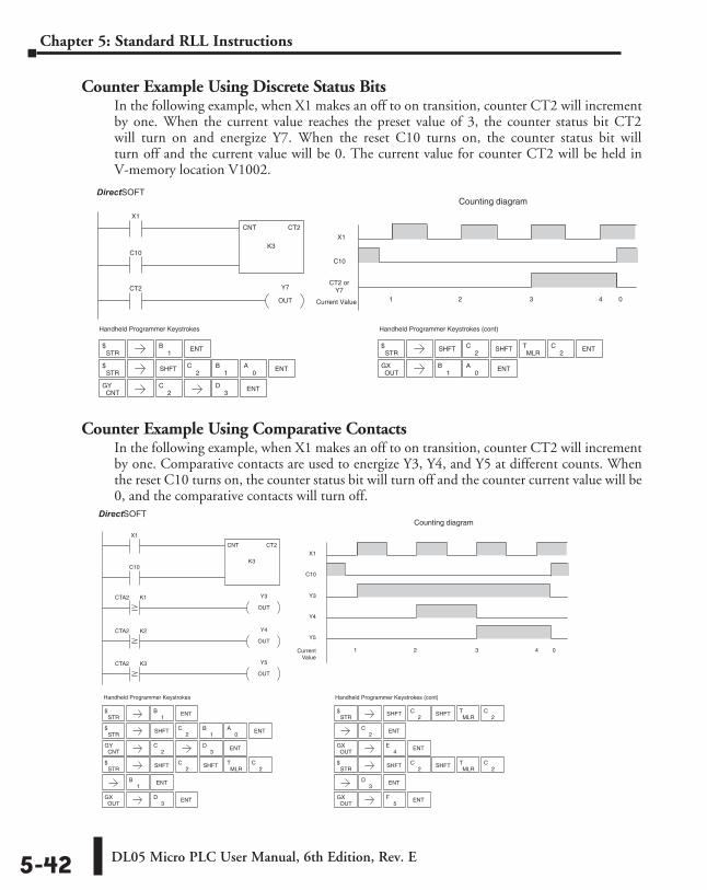
DL05 Micro PLC User Manual, 6th Edition, Rev. E5-42
Chapter 5: Standard RLL Instructions
Counter Example Using Discrete Status BitsIn the following example, when X1 makes an off to on transition, counter CT2 will increment by one. When the current value reaches the preset value of 3, the counter status bit CT2 will turn on and energize Y7. When the reset C10 turns on, the counter status bit will turn off and the current value will be 0. The current value for counter CT2 will be held in V-memory location V1002.
Counter Example Using Comparative ContactsIn the following example, when X1 makes an off to on transition, counter CT2 will increment by one. Comparative contacts are used to energize Y3, Y4, and Y5 at different counts. When the reset C10 turns on, the counter status bit will turn off and the counter current value will be 0, and the comparative contacts will turn off.
2C
Handheld Programmer Keystrokes
CT2
X1
CNT CT2
K3C10
Y7
OUT
X1
CT2 or Y7
1 2 3 4 0Current Value
C10
Counting diagramDirectSOFT32
STR$
1B ENT
3D ENT
STR$ SHFT ENT
2C
1B
0A
CNTGY
STR$ SHFT ENT
OUTGX ENT
0A
1B
2C
MLRT
2C
Handheld Programmer Keystrokes (cont)
SHFT
Handheld Programmer Keystrokes
X1
CNT CT2
K3C10
X1
Y3
1 2 3 4 0CurrentValue
C10
Counting diagram
CTA2 K1
CTA2 K2
CTA2 K3
Y4
OUT
Y3
OUT
Y5
OUT
Y4
Y5
DirectSOFT32
Handheld Programmer Keystrokes (cont)
STR$ SHFT
ENT
OUTGX ENT
2C
4E
STR$ SHFT
2C
ENT
OUTGX ENT
3D
5F
STR$
1B ENT
2C
STR$ SHFT
1B ENT
OUTGX ENT
3D
STR$ SHFT ENT
2C
1B
0A
CNTGY ENT
3D
MLRT
2C
2C
MLRT
2C
2C
MLRT
2CSHFT
SHFT
SHFT
DirectSOFT
DirectSOFT
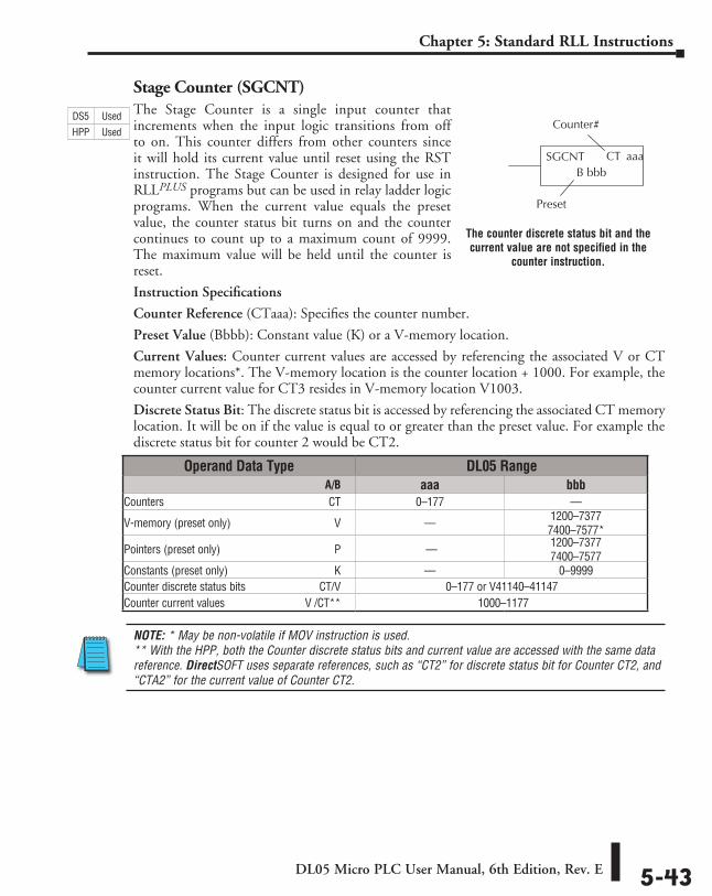
DL05 Micro PLC User Manual, 6th Edition, Rev. E 5-43
Chapter 5: Standard RLL Instructions
Stage Counter (SGCNT)The Stage Counter is a single input counter that increments when the input logic transitions from off to on. This counter differs from other counters since it will hold its current value until reset using the RST instruction. The Stage Counter is designed for use in RLLPLUS programs but can be used in relay ladder logic programs. When the current value equals the preset value, the counter status bit turns on and the counter continues to count up to a maximum count of 9999. The maximum value will be held until the counter is reset.
Instruction Specifications
Counter Reference (CTaaa): Specifies the counter number.
Preset Value (Bbbb): Constant value (K) or a V-memory location.
Current Values: Counter current values are accessed by referencing the associated V or CT memory locations*. The V-memory location is the counter location + 1000. For example, the counter current value for CT3 resides in V-memory location V1003.
Discrete Status Bit: The discrete status bit is accessed by referencing the associated CT memory location. It will be on if the value is equal to or greater than the preset value. For example the discrete status bit for counter 2 would be CT2.
NOTE: * May be non-volatile if MOV instruction is used. ** With the HPP, both the Counter discrete status bits and current value are accessed with the same data reference. DirectSOFT uses separate references, such as “CT2” for discrete status bit for Counter CT2, and “CTA2” for the current value of Counter CT2.
CT aaaSGCNTB bbb
Preset
Counter #
Operand Data Type DL05 Range ⸠⸠⸠⸠⸠⸠⸠⸠⸠⸠⸠⸠⸠⸠⸠⸠⸠⸠⸠⸠⸠⸠⸠⸠⸠⸠⸠⸠⸠⸠⸠⸠⸠⸠⸠⸠⸠⸠⸠⸠⸠⸠⸠⸠⸠⸠⸠⸠⸠⸠⸠⸠⸠⸠⸠⸠⸠⸠⸠⸠⸠⸠⸠⸠⸠⸠⸠⸠⸠ A/B aaa bbbCounters ⸠⸠⸠⸠⸠⸠⸠⸠⸠⸠⸠⸠⸠⸠⸠⸠⸠⸠⸠⸠⸠⸠⸠⸠⸠⸠⸠⸠⸠⸠⸠⸠⸠⸠⸠⸠⸠⸠⸠⸠⸠⸠⸠⸠⸠⸠⸠⸠⸠⸠⸠⸠⸠⸠⸠⸠⸠⸠⸠CT 0–177 ––
V-memory (preset only) ⸠⸠⸠⸠⸠⸠⸠⸠⸠⸠⸠⸠⸠⸠⸠⸠⸠⸠⸠⸠⸠⸠⸠⸠⸠⸠⸠⸠⸠⸠⸠⸠⸠⸠⸠⸠V –– 1200–7377 7400–7577*
Pointers (preset only) ⸠⸠⸠⸠⸠⸠⸠⸠⸠⸠⸠⸠⸠⸠⸠⸠⸠⸠⸠⸠⸠⸠⸠⸠⸠⸠⸠⸠⸠⸠⸠⸠⸠⸠⸠⸠⸠⸠⸠⸠P –– 1200–7377 7400–7577
Constants (preset only) ⸠⸠⸠⸠⸠⸠⸠⸠⸠⸠⸠⸠⸠⸠⸠⸠⸠⸠⸠⸠⸠⸠⸠⸠⸠⸠⸠⸠⸠⸠⸠⸠⸠⸠⸠⸠⸠K –– 0–9999Counter discrete status bits ⸠⸠⸠⸠⸠⸠⸠⸠⸠⸠⸠⸠⸠⸠⸠⸠⸠⸠⸠⸠⸠⸠⸠⸠⸠ CT/V 0–177 or V41140–41147Counter current values ⸠⸠⸠⸠⸠⸠⸠⸠⸠⸠⸠⸠⸠⸠⸠⸠⸠⸠⸠⸠⸠⸠⸠⸠⸠⸠⸠V /CT** 1000–1177
The counter discrete status bit and the current value are not specified in the
counter instruction.
DS5 Used
HPP Used
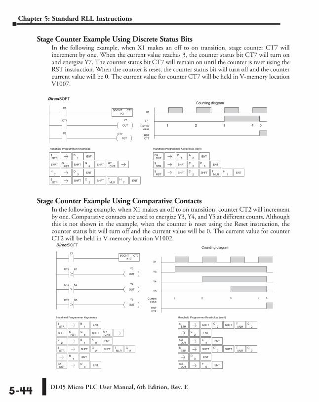
DL05 Micro PLC User Manual, 6th Edition, Rev. E5-44
Chapter 5: Standard RLL Instructions
Stage Counter Example Using Discrete Status BitsIn the following example, when X1 makes an off to on transition, stage counter CT7 will increment by one. When the current value reaches 3, the counter status bit CT7 will turn on and energize Y7. The counter status bit CT7 will remain on until the counter is reset using the RST instruction. When the counter is reset, the counter status bit will turn off and the counter current value will be 0. The current value for counter CT7 will be held in V-memory location V1007.
Stage Counter Example Using Comparative ContactsIn the following example, when X1 makes an off to on transition, counter CT2 will increment by one. Comparative contacts are used to energize Y3, Y4, and Y5 at different counts. Although this is not shown in the example, when the counter is reset using the Reset instruction, the counter status bit will turn off and the current value will be 0. The current value for counter CT2 will be held in V-memory location V1002.
3D
7H
Handheld Programmer Keystrokes
X1
C5 CT7
SGCNT CT7K3
RST
X1
Y7
1 2 3 4 0CurrentValue
RSTCT7
CT7 Y7
OUT
Counting diagramDirectSOFT32
STR$
1B ENT
CNTGY
STR$ SHFT ENT
OUTGX ENT
0A
1B
2C
MLRT
7H
STR$ SHFT ENT
2C
5F
RSTS SHFT
2C
7H ENT
SHFTRST
S6
G SHFT
ENT
Handheld Programmer Keystrokes (cont)
SHFT
SHFT
SHFTMLR
T
Handheld Programmer Keystrokes
X1
X1
Y3
1 2 3 4 0Current Value
Counting diagram
CT2 K1
CT2 K2
CT2 K3
Y4
OUT
Y3
OUT
Y5
OUT
Y4
Y5
SGCNT CT2K10
DirectSOFT32
Handheld Programmer Keystrokes (cont)
STR$
1B ENT
CNTGYSHFT
RSTS
6G SHFT
ENT2
C1
B0
A
STR$ SHFT
1B ENT
OUTGX ENT
3D
MLRT
2C
2C
STR$ SHFT
ENT
OUTGX ENT
2C
4E
STR$ SHFT
2C
ENT
OUTGX ENT
3D
5F
MLRT
2C
2C
MLRT
2CSHFT
SHFT
SHFT
RST CT2
DirectSOFT
DirectSOFT
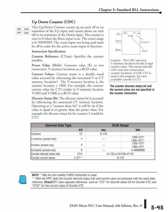
DL05 Micro PLC User Manual, 6th Edition, Rev. E 5-45
Chapter 5: Standard RLL Instructions
Up Down Counter (UDC)This Up/Down Counter counts up on each off to on transition of the Up input and counts down on each off to on transition of the Down input. The counter is reset to 0 when the Reset input is on. The count range is 0–99999999. The count input not being used must be off in order for the active count input to function.
Instruction Specification
Counter Reference (CTaaa): Specifies the counter number.
Preset Value (Bbbb): Constant value (K) or two consecutive V-memory locations as a BCD value.
Current Values: Current count is a double word value accessed by referencing the associated V or CT memory locations*. The V-memory location is the counter location + 1000. For example, the counter current value for CT5 resides in V-memory location V1005 and V1006 as a BCD value.
Discrete Status Bit: The discrete status bit is accessed by referencing the associated CT memory location. Operating as a “counter done bit” it will be on if the value is equal to or greater than the preset value. For example the discrete status bit for counter 2 would be CT2.
NOTE: * May be non-volatile if MOV instruction is used. ** With the HPP, both the Counter discrete status bits and current value are accessed with the same data reference. DirectSOFT uses separate references, such as “CT2” for discrete status bit for Counter CT2, and “CTA2” for the current value of Counter CT2.
CT aaaUDCB bbb
Up
Down
Reset
Caution: The UDC uses two V-memory locations for the 8 digitcurrent value. This means that theUDC uses two consecutivecounter locations. If UDC CT1 isused in the program, the nextavailable counter is CT3.
Preset
Counter #
Operand Data Type DL05 Range ⸠⸠⸠⸠⸠⸠⸠⸠⸠⸠⸠⸠⸠⸠⸠⸠⸠⸠⸠⸠⸠⸠⸠⸠⸠⸠⸠⸠⸠⸠⸠⸠⸠⸠⸠⸠⸠⸠⸠⸠⸠⸠⸠⸠⸠⸠⸠⸠⸠⸠⸠⸠⸠⸠⸠⸠⸠⸠⸠⸠⸠⸠⸠⸠⸠⸠⸠⸠⸠ A/B aaa bbbCounters ⸠⸠⸠⸠⸠⸠⸠⸠⸠⸠⸠⸠⸠⸠⸠⸠⸠⸠⸠⸠⸠⸠⸠⸠⸠⸠⸠⸠⸠⸠⸠⸠⸠⸠⸠⸠⸠⸠⸠⸠⸠⸠⸠⸠⸠⸠⸠⸠⸠⸠⸠⸠⸠⸠⸠⸠⸠⸠⸠CT 0–176 ––
V-memory (preset only) ⸠⸠⸠⸠⸠⸠⸠⸠⸠⸠⸠⸠⸠⸠⸠⸠⸠⸠⸠⸠⸠⸠⸠⸠⸠⸠⸠⸠⸠⸠⸠⸠⸠⸠⸠⸠V –– 1200–7377 7400–7577*
Pointers (preset only) ⸠⸠⸠⸠⸠⸠⸠⸠⸠⸠⸠⸠⸠⸠⸠⸠⸠⸠⸠⸠⸠⸠⸠⸠⸠⸠⸠⸠⸠⸠⸠⸠⸠⸠⸠⸠⸠⸠⸠⸠P –– 1200–7377 7400–7577
Constants (preset only) ⸠⸠⸠⸠⸠⸠⸠⸠⸠⸠⸠⸠⸠⸠⸠⸠⸠⸠⸠⸠⸠⸠⸠⸠⸠⸠⸠⸠⸠⸠⸠⸠⸠⸠⸠⸠⸠K –– 0–99999999Counter discrete status bits ⸠⸠⸠⸠⸠⸠⸠⸠⸠⸠⸠⸠⸠⸠⸠⸠⸠⸠⸠⸠⸠⸠⸠⸠⸠ CT/V 0–176 or V41140–41147Counter current values ⸠⸠⸠⸠⸠⸠⸠⸠⸠⸠⸠⸠⸠⸠⸠⸠⸠⸠⸠⸠⸠⸠⸠⸠⸠⸠⸠V /CT** 0–176
The counter discrete status bit and the current value are not specified in the counter instruction
DS5 Used
HPP Used
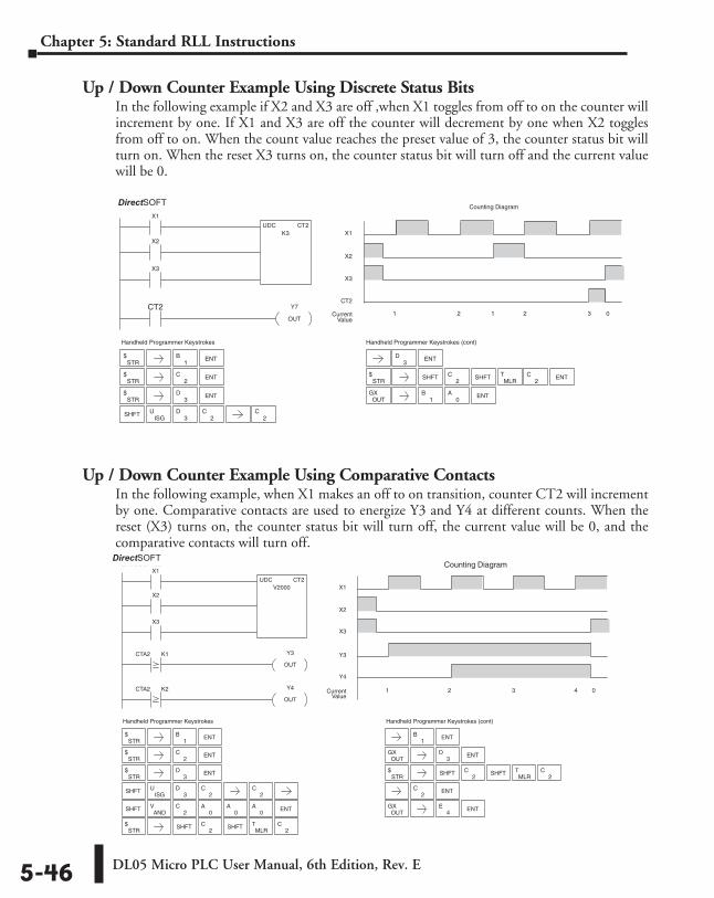
DL05 Micro PLC User Manual, 6th Edition, Rev. E5-46
Chapter 5: Standard RLL Instructions
Up / Down Counter Example Using Discrete Status BitsIn the following example if X2 and X3 are off ,when X1 toggles from off to on the counter will increment by one. If X1 and X3 are off the counter will decrement by one when X2 toggles from off to on. When the count value reaches the preset value of 3, the counter status bit will turn on. When the reset X3 turns on, the counter status bit will turn off and the current value will be 0.
Up / Down Counter Example Using Comparative ContactsIn the following example, when X1 makes an off to on transition, counter CT2 will increment by one. Comparative contacts are used to energize Y3 and Y4 at different counts. When the reset (X3) turns on, the counter status bit will turn off, the current value will be 0, and the comparative contacts will turn off.
3D ENT
Handheld Programmer Keystrokes
X1
UDC CT2K3
X2
X3
CT2 Y7
OUT
X1
CT2
1 2 1 2 3 0CurrentValue
X2
X3
Counting DiagramDirectSOFT32
Handheld Programmer Keystrokes (cont)
STR$
1B ENT
STR$
2C
STR$
3D
SHFTISG
U3
D2
C2
C
ENT
ENTSTR
$ SHFT ENT
OUTGX ENT
0A
1B
2C
MLRT
2CSHFT
ANDV
Handheld Programmer Keystrokes
X1
UDC CT2V2000
X2
X3
X1
X2
X3
Counting Diagram
CTA2 K1
CTA2 K2 Y4
OUT
Y3
OUT
Y3
1 2 3 4 0CurrentValue
Y4
DirectSOFT32
Handheld Programmer Keystrokes (cont)
STR$
1B ENT
STR$
2C
STR$
3D
SHFTISG
U3
D2
C2
C
ENT
ENT
SHFT ENT2
C0
A0
A0
A
STR$ SHFT
1B ENT
OUTGX ENT
3D
MLRT
2C
2C
STR$ SHFT
ENT
OUTGX ENT
MLRT
2C
2C
2C
4E
SHFT
SHFT
DirectSOFT
DirectSOFT
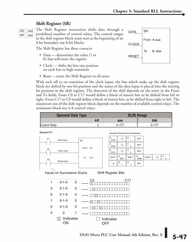
DL05 Micro PLC User Manual, 6th Edition, Rev. E 5-47
Chapter 5: Standard RLL Instructions
Shift Register (SR)The Shift Register instruction shifts data through a predefined number of control relays. The control ranges in the shift register block must start at the beginning of an 8 bit boundary use 8-bit blocks.
The Shift Register has three contacts.
• Data — determines the value (1 or 0) that will enter the register
• Clock — shifts the bits one position on each low to high transition
• Reset —resets the Shift Register to all zeros.
With each off to on transition of the clock input, the bits which make up the shift register block are shifted by one bit position and the status of the data input is placed into the starting bit position in the shift register. The direction of the shift depends on the entry in the From and To fields. From C0 to C17 would define a block of sixteen bits to be shifted from left to right. From C17 to C0 would define a block of sixteen bits, to be shifted from right to left. The maximum size of the shift register block depends on the number of available control relays. The minimum block size is 8 control relays.
SR
aaaFrom A
bbbTo B
DATA
CLOCK
RESET
Data Input
Clock Input
Reset Input
Shift Register Bits
C0 C17
1 0-1-0 0
0 0-1-0 0
0 0-1-0 0
1 0-1-0 0
0 0-1-0 0
0 0 1
Inputs on Successive Scans
X1
X2
SR
C0From
C17X3
To
Handheld Programmer KeystrokesDirect SOFT32
STR$
1B ENT
STR$
2C
STR$
3D
SHFT
ENT
ENT
RSTS
ORNR SHFT
0A
1B
7H ENT
SHFT
Indicates ON
IndicatesOFF
Operand Data Type DL05 Range ⸠⸠⸠⸠⸠⸠⸠⸠⸠⸠⸠⸠⸠⸠⸠⸠⸠⸠⸠⸠⸠⸠⸠⸠⸠⸠⸠⸠⸠⸠⸠⸠⸠⸠⸠⸠⸠⸠⸠⸠⸠⸠⸠⸠⸠⸠⸠⸠⸠⸠⸠⸠⸠⸠⸠⸠⸠⸠⸠⸠⸠⸠⸠⸠⸠⸠⸠⸠⸠ A/B aaa bbbControl Relay ⸠⸠⸠⸠⸠⸠⸠⸠⸠⸠⸠⸠⸠⸠⸠⸠⸠⸠⸠⸠⸠⸠⸠⸠⸠⸠⸠⸠⸠⸠⸠⸠⸠⸠⸠⸠⸠⸠⸠⸠⸠⸠⸠⸠⸠⸠⸠⸠⸠⸠⸠⸠⸠C 0–777 0–777
DS5 Used
HPP Used
DirectSOFT
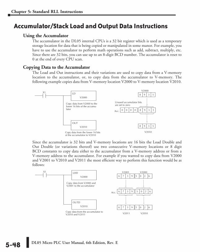
DL05 Micro PLC User Manual, 6th Edition, Rev. E5-48
Chapter 5: Standard RLL Instructions
Accumulator/Stack Load and Output Data InstructionsUsing the Accumulator
The accumulator in the DL05 internal CPUs is a 32 bit register which is used as a temporary storage location for data that is being copied or manipulated in some manor. For example, you have to use the accumulator to perform math operations such as add, subtract, multiply, etc. Since there are 32 bits, you can use up to an 8-digit BCD number. The accumulator is reset to 0 at the end of every CPU scan.
Copying Data to the AccumulatorThe Load and Out instructions and their variations are used to copy data from a V-memory location to the accumulator, or, to copy data from the accumulator to V-memory. The following example copies data from V-memory location V2000 to V-memory location V2010.
Since the accumulator is 32 bits and V-memory locations are 16 bits the Load Double and Out Double (or variations thereof) use two consecutive V-memory locations or 8 digit BCD constants to copy data either to the accumulator from a V-memory address or from a V-memory address to the accumulator. For example if you wanted to copy data from V2000 and V2001 to V2010 and V2011 the most efficient way to perform this function would be as follows:
LD
V2000
X1
Copy data from V2000 to thelower 16 bits of the accumu-lator
Copy data from the lower 16 bitsof the accumulator to V2010
OUT
V2010
V2010
Acc.
8 9 3 5
8 9 3 5
0 0 0 0 8 9 3 5 8 9 3 5
Unused accumulator bitsare set to zero
V2000
LDD
V2000
Copy data from V2000 andV2001 to the accumulator
Copy data from the accumulator toV2010 and V2011
OUTD
V2010
V2010
Acc.
V2000
6 7 3 9 5 0 2 6 5 0 2 6
X1 V2001
6 7 3 9 5 0 2 6
V2011
6 7 3 9 5 0 2 6
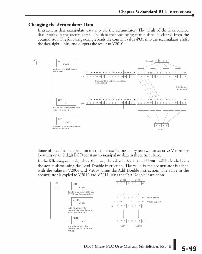
DL05 Micro PLC User Manual, 6th Edition, Rev. E 5-49
Chapter 5: Standard RLL Instructions
Changing the Accumulator DataInstructions that manipulate data also use the accumulator. The result of the manipulated data resides in the accumulator. The data that was being manipulated is cleared from the accumulator. The following example loads the constant value 4935 into the accumulator, shifts the data right 4 bits, and outputs the result to V2010.
Some of the data manipulation instructions use 32 bits. They use two consecutive V-memory locations or an 8 digit BCD constant to manipulate data in the accumulator.
In the following example, when X1 is on, the value in V2000 and V2001 will be loaded into the accumulator using the Load Double instruction. The value in the accumulator is added with the value in V2006 and V2007 using the Add Double instruction. The value in the accumulator is copied to V2010 and V2011 using the Out Double instruction.
LD
K4935
X1
Load the value 4935 into theaccumulator
Shift the data in the accumulator4 bits (K4) to the right
Output the lower 16 bits of the ac-cumulator to V2010
0 1 0 0 1 0 0 1 0 0 1 1 0 1 0 1
Constant
V2010
0 0 0 0 0 1 0 0 1 0 0 1 0 0 1 10 0 0 0 0 1 0 0 0 0 0 0 0 0 0 0
15 14 13 12 11 10 9 8 7 6 5 4 3 2 1 031 30 29 28 27 26 25 24 23 22 21 20 19 18 17 16
Shifted out ofaccumulator
0 4 9 3
4 9 3 5
SHFR
K4
OUT
V2010
0 0 0 0 0 0 0 0 0 0 0 0 0 0 0 0
31 30 29 28 27 26 25 24 23 22 21 20 19 18 17 16
0 0 0 0 0 0 0 0 0 0 0 0 0 0 0 0
The upper 16 bits of the accumulatorwill be set to 0
15 14 13 12 11 10 9 8 7 6 5 4 3 2 1 031 30 29 28 27 26 25 24 23 22 21 20 19 18 17 1631 30 29 28 27 26 25 24 23 22 21 20 19 18 17 16
Acc.
Acc.
6 7 3 9 5 0 2 6
LDD
V2000
X1
Load the value in V2000 andV2001 into the accumulator
ADDD
V2006
Add the value in theaccumulator with the valuein V2006 and V2007
OUTD
V2010
Copy the value in theaccumulator to V2010 andV2011
V2010
V2000
V2001
6 7 3 9 5 0 2 6
V2011
8 7 3 9 9 0 7 2
(Accumulator)
(V2006 & V2007) 2 0 0 0 4 0 4 6 +
8 7 3 9 9 0 7 2 Acc.
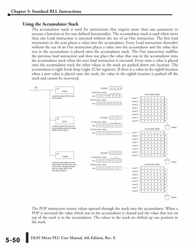
DL05 Micro PLC User Manual, 6th Edition, Rev. E5-50
Chapter 5: Standard RLL Instructions
Using the Accumulator StackThe accumulator stack is used for instructions that require more than one parameter to execute a function or for user defined functionality. The accumulator stack is used when more than one Load instruction is executed without the use of an Out instruction. The first load instruction in the scan places a value into the accumulator. Every Load instruction thereafter without the use of an Out instruction places a value into the accumulator and the value that was in the accumulator is placed onto the accumulator stack. The Out instruction nullifies the previous load instruction and does not place the value that was in the accumulator onto the accumulator stack when the next load instruction is executed. Every time a value is placed onto the accumulator stack the other values in the stack are pushed down one location. The accumulator is eight levels deep (eight 32 bit registers). If there is a value in the eighth location when a new value is placed onto the stack, the value in the eighth location is pushed off the stack and cannot be recovered.
The POP instruction rotates values upward through the stack into the accumulator. When a POP is executed the value which was in the accumulator is cleared and the value that was on top of the stack is in the accumulator. The values in the stack are shifted up one position in the stack.
Acc.Load the value 3245 into the accumulator
Load the value 5151 into the accumulator, pushing the value 3245 onto the stack
Load the value 6363 into the accumulator, pushing the value 5151 to the 1st stack location and the value 3245 to the 2nd stack location
LD
K3245
X1
LD
K5151
LD
K6363
Constant
Acc. X X X X X X X X X
Current Acc. value
Previous Acc. valueX X X X X X X XX X X X X X XX X X X X X X
Level 1
X X X X X X X X Level 2
X X X X X X X X Level 3
X X X X X X X X Level 4
X X X X X X X X Level 5
X X X X X X X X Level 6
X X X X X X X X Level 7
X X X X X X X X Level 8
Accumulator Stack
0 0 0 0 3 2 4 5 Level 1
X X X X X X X X Level 2
X X X X X X X X Level 3
X X X X X X X X Level 4
X X X X X X X X Level 5
X X X X X X X X Level 6
X X X X X X X X Level 7
X X X X X X X X Level 8
Accumulator Stack
Acc.
Constant 5 1 5 1
0 0 0 0 5 5 1 5 1
Acc. 0 0 0 0 3 2 4 5 3 2 4 5
Current Acc. value
Previous Acc. value
0 0 0 0 5 1 5 1
0 0 0 0
Level 1
0 0 0 0 3 2 4 5 Level 2
X X X X X X X X Level 3
X X X X X X X X Level 4
X X X X X X X X Level 5
X X X X X X X X Level 6
X X X X X X X X Level 7
X X X X X X X X Level 8
Accumulator Stack
Acc.
Constant 6 3 6 3
0 0 0 0 6 3 6 3 6 3 6 3
Acc. 0 0 0 0 5 5 1 5 1
Current Acc. value
Previous Acc. value
Bucket
Bucket
Bucket
3 2 4 5
0 0 0 0 3 2 4 5
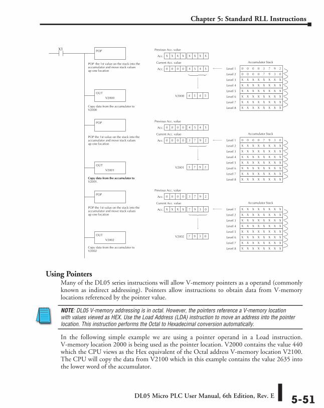
DL05 Micro PLC User Manual, 6th Edition, Rev. E 5-51
Chapter 5: Standard RLL Instructions
Using PointersMany of the DL05 series instructions will allow V-memory pointers as a operand (commonly known as indirect addressing). Pointers allow instructions to obtain data from V-memory locations referenced by the pointer value.
NOTE: DL05 V-memory addressing is in octal. However, the pointers reference a V-memory location with values viewed as HEX. Use the Load Address (LDA) instruction to move an address into the pointer location. This instruction performs the Octal to Hexadecimal conversion automatically.
In the following simple example we are using a pointer operand in a Load instruction. V-memory location 2000 is being used as the pointer location. V2000 contains the value 440 which the CPU views as the Hex equivalent of the Octal address V-memory location V2100. The CPU will copy the data from V2100 which in this example contains the value 2635 into the lower word of the accumulator.
Acc.
POP the 1st value on the stack into theaccumulator and move stack valuesup one location
POPX1
POP
POP
V2000 4 5 4 5
X X X X X X X X X X X
Acc. 0 0 0 0 4 5 4 5 4 5
Previous Acc. value
Current Acc. value
0 0 0 0 3 7 9 2 Level 1
0 0 0 0 7 9 3 0 Level 2
X X X X X X X X
Level 3
X X X X X X X X Level 4
X X X X X X X X Level 5
X X X X X X X X Level 6
X X X X X X X X Level 7
X X X X X X X X Level 8
Accumulator Stack
0 0 0 0 7 9 3 0 Level 1
X X X X X X X X Level 2
X X X X X X X X Level 3
X X X X X X X X Level 4
X X X X X X X X Level 5
X X X X X X X X Level 6
X X X X X X X X Level 7
X X X X X X X X Level 8
Accumulator Stack
X X X X X X X X Level 1
X X X X X X X X Level 2
X X X X X X X X Level 3
X X X X X X X X Level 4
X X X X X X X X Level 5
X X X X X X X X Level 6
X X X X X X X X Level 7
X X X X X X X X Level 8
Accumulator Stack
POP the 1st value on the stack into theaccumulator and move stack valuesup one location
POP the 1st value on the stack into theaccumulator and move stack valuesup one location
OUT
V2000
OUT
V2001
Acc.
V2001 3 7 9 2
0 0 0 0 4 5 4 5 4 5 4 5
Acc. 0 0 0 0 3 7 9 2 3 7 9 2
Previous Acc. value
Current Acc. value
Acc.
V2002 7 9 3 0
0 0 0 0 3 4 6 0 3 7 9 2
Acc. X X X X 7 9 3 0 7 9 3 0
Previous Acc. value
Current Acc. value
OUT
V2002
Copy data from the accumulator toV2000
Copy data from the accumulator toV2001.Copy data from the accumulator to
Copy data from the accumulator toV2002
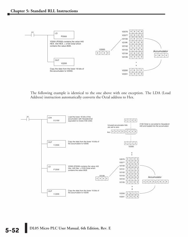
DL05 Micro PLC User Manual, 6th Edition, Rev. E5-52
Chapter 5: Standard RLL Instructions
The following example is identical to the one above with one exception. The LDA (Load Address) instruction automatically converts the Octal address to Hex.
V2000 (P2000) contains the value 440HEX. 440 HEX. = 2100 Octal whichcontains the value 2635.
LD
P2000
X1
OUT
V2200
Copy the data from the lower 16 bits ofthe accumulator to V2200.
0 4 4 0
V2076 X X X X
V2077 X X X X
V2100 2 6 3 5
V2101 X X X X
V2102 X X X X
V2103 X X X X
V2104 X X X X
V2105 X X X X
V2200 2 6 3 5
V2201 X X X X
2 6 3 5
AccumulatorV2000
V2000 (P2000) contains the value 440Hex. 440 Hex. = 2100 Octal whichcontains the value 2635
LDA
O 2100
X1
OUT
V 2000
Copy the data from the lower 16 bits ofthe accumulator to V2000
V2100
0 4 4 0
V2076 X X X X
V2077 X X X X
V2100 2 6 3 5
V2101 X X X X
V2102 X X X X
V2103 X X X X
V2104 X X X X
V2105 X X X X
V2200 2 6 3 5
V2201 X X X X
LD
P 2000
OUT
V 2200
Copy the data from the lower 16 bits ofthe accumulator to V2200
Load the lower 16 bits of theaccumulator with Hexadecimalequivalent to Octal 2100 (440)
V2000
Acc.
2 1 0 0
0 4 4 0
0 0 0 0 0 4 4 0 0 4 4 0
2100 Octal is converted to Hexadecimal440 and loaded into the accumulator
Accumulator
0 0 0 0 2 6 3 5 2 6 3 5
Unused accumulator bitsare set to zero
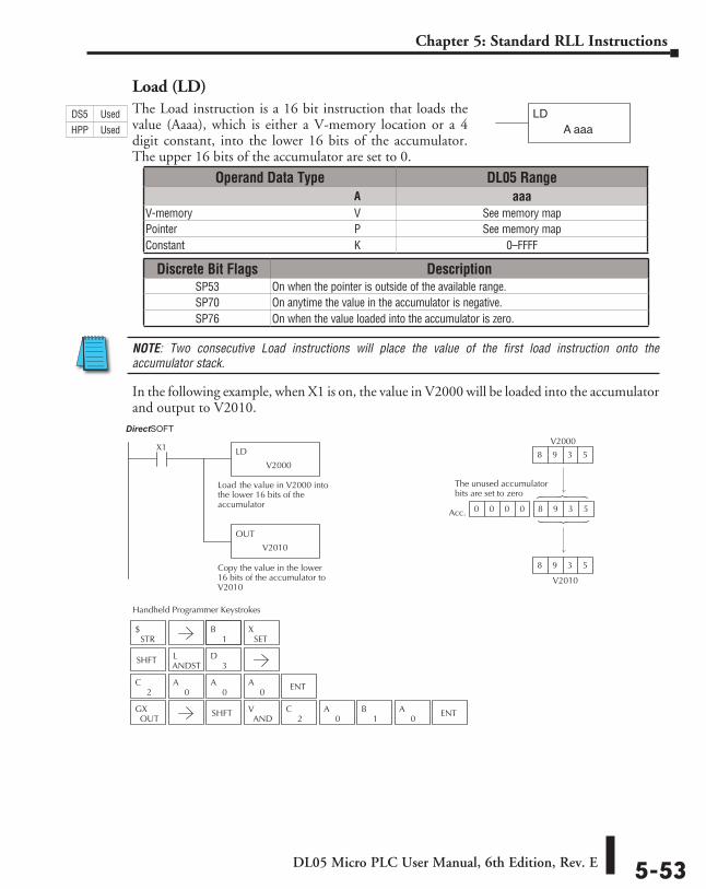
DL05 Micro PLC User Manual, 6th Edition, Rev. E 5-53
Chapter 5: Standard RLL Instructions
Load (LD)The Load instruction is a 16 bit instruction that loads the value (Aaaa), which is either a V-memory location or a 4 digit constant, into the lower 16 bits of the accumulator. The upper 16 bits of the accumulator are set to 0.
NOTE: Two consecutive Load instructions will place the value of the first load instruction onto the accumulator stack.
In the following example, when X1 is on, the value in V2000 will be loaded into the accumulator and output to V2010.
LDA aaa
Operand Data Type DL05 Range ⸠⸠⸠⸠⸠⸠⸠⸠⸠⸠⸠⸠⸠⸠⸠⸠⸠⸠⸠⸠⸠⸠⸠⸠⸠⸠⸠⸠⸠⸠⸠⸠⸠⸠⸠⸠⸠⸠⸠⸠⸠⸠⸠⸠⸠⸠⸠⸠⸠⸠⸠⸠⸠⸠⸠⸠⸠⸠⸠⸠⸠⸠⸠⸠⸠⸠⸠⸠⸠⸠⸠⸠⸠A aaaV-memory ⸠⸠⸠⸠⸠⸠⸠⸠⸠⸠⸠⸠⸠⸠⸠⸠⸠⸠⸠⸠⸠⸠⸠⸠⸠⸠⸠⸠⸠⸠⸠⸠⸠⸠⸠⸠⸠⸠⸠⸠⸠⸠⸠⸠⸠⸠⸠⸠⸠⸠⸠⸠⸠⸠⸠⸠⸠⸠V See memory mapPointer ⸠⸠⸠⸠⸠⸠⸠⸠⸠⸠⸠⸠⸠⸠⸠⸠⸠⸠⸠⸠⸠⸠⸠⸠⸠⸠⸠⸠⸠⸠⸠⸠⸠⸠⸠⸠⸠⸠⸠⸠⸠⸠⸠⸠⸠⸠⸠⸠⸠⸠⸠⸠⸠⸠⸠⸠⸠⸠⸠⸠⸠⸠⸠⸠P See memory mapConstant ⸠⸠⸠⸠⸠⸠⸠⸠⸠⸠⸠⸠⸠⸠⸠⸠⸠⸠⸠⸠⸠⸠⸠⸠⸠⸠⸠⸠⸠⸠⸠⸠⸠⸠⸠⸠⸠⸠⸠⸠⸠⸠⸠⸠⸠⸠⸠⸠⸠⸠⸠⸠⸠⸠⸠⸠⸠⸠⸠⸠⸠K 0–FFFF
Discrete Bit Flags DescriptionSP53 On when the pointer is outside of the available range.SP70 On anytime the value in the accumulator is negative.SP76 On when the value loaded into the accumulator is zero.
DS5 Used
HPP Used
LD
V2000
X1
Load the value in V2000 intothe lower 16 bits of theaccumulator
OUT
V2010
Copy the value in the lower16 bits of the accumulator toV2010
V2010
Acc.
V2000
8 9 3 5
8 9 3 5
0 0 0 0 8 9 3 5 8 9 3 5
Direct SOFT32
The unused accumulatorbits are set to zero
1B
2C
0A
0A
0A ENT
Handheld Programmer Keystrokes
STR$
SETX
SHFTANDSTL
3D
OUTGX SHFT
ANDV
2C
0A
1B
0A ENT
DirectSOFT
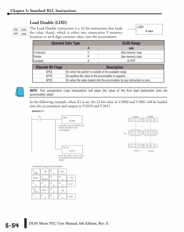
DL05 Micro PLC User Manual, 6th Edition, Rev. E5-54
Chapter 5: Standard RLL Instructions
Load Double (LDD)The Load Double instruction is a 32 bit instruction that loads the value (Aaaa), which is either two consecutive V-memory locations or an 8 digit constant value, into the accumulator.
NOTE: Two consecutive Load instructions will place the value of the first load instruction onto the accumulator stack.
In the following example, when X1 is on, the 32 bit value in V2000 and V2001 will be loaded into the accumulator and output to V2010 and V2011.
Operand Data Type DL05 Range ⸠⸠⸠⸠⸠⸠⸠⸠⸠⸠⸠⸠⸠⸠⸠⸠⸠⸠⸠⸠⸠⸠⸠⸠⸠⸠⸠⸠⸠⸠⸠⸠⸠⸠⸠⸠⸠⸠⸠⸠⸠⸠⸠⸠⸠⸠⸠⸠⸠⸠⸠⸠⸠⸠⸠⸠⸠⸠⸠⸠⸠⸠⸠⸠⸠⸠⸠⸠⸠⸠⸠⸠⸠A aaaV-memory ⸠⸠⸠⸠⸠⸠⸠⸠⸠⸠⸠⸠⸠⸠⸠⸠⸠⸠⸠⸠⸠⸠⸠⸠⸠⸠⸠⸠⸠⸠⸠⸠⸠⸠⸠⸠⸠⸠⸠⸠⸠⸠⸠⸠⸠⸠⸠⸠⸠⸠⸠⸠⸠⸠⸠⸠⸠⸠V See memory mapPointer ⸠⸠⸠⸠⸠⸠⸠⸠⸠⸠⸠⸠⸠⸠⸠⸠⸠⸠⸠⸠⸠⸠⸠⸠⸠⸠⸠⸠⸠⸠⸠⸠⸠⸠⸠⸠⸠⸠⸠⸠⸠⸠⸠⸠⸠⸠⸠⸠⸠⸠⸠⸠⸠⸠⸠⸠⸠⸠⸠⸠⸠⸠⸠⸠P See memory mapConstant ⸠⸠⸠⸠⸠⸠⸠⸠⸠⸠⸠⸠⸠⸠⸠⸠⸠⸠⸠⸠⸠⸠⸠⸠⸠⸠⸠⸠⸠⸠⸠⸠⸠⸠⸠⸠⸠⸠⸠⸠⸠⸠⸠⸠⸠⸠⸠⸠⸠⸠⸠⸠⸠⸠⸠⸠⸠⸠⸠⸠⸠K 0–FFFF
Discrete Bit Flags DescriptionSP53 On when the pointer is outside of the available range.SP70 On anytime the value in the accumulator is negative.SP76 On when the value loaded into the accumulator by any instruction is zero.
LDDA aaa
1B ENT
2C
0A
0A
0A ENT
2C
0A
1B
0A ENT
Handheld Programmer Keystrokes
Direct SOFT32
LDD
V2000
X1
Load the value in V2000 andV2001 into the 32 bitaccumulator
OUTD
V2010
Copy the value in the 32 bitaccumulator to V2010 andV2011
V2010
Acc.
V2000
6 7 3 9 6 0 2 6 5 0 2 6
V2001
6 7 3 9 5 0 2 6
V2011
6 7 3 9 5 0 2 6
STR$
SHFTANDSTL
3D
3D
OUTGX SHFT
3D
DS5 Used
HPP Used
DirectSOFT
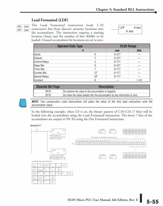
DL05 Micro PLC User Manual, 6th Edition, Rev. E 5-55
Chapter 5: Standard RLL Instructions
Load Formatted (LDF)The Load Formatted instruction loads 1–32 consecutive bits from discrete memory locations into the accumulator. The instruction requires a starting location (Aaaa) and the number of bits (Kbbb) to be loaded. Unused accumulator bit locations are set to zero.
NOTE: Two consecutive Load instructions will place the value of the first load instruction onto the accumulator stack.
In the following example, when C0 is on, the binary pattern of C10–C16 (7 bits) will be loaded into the accumulator using the Load Formatted instruction. The lower 7 bits of the accumulator are output to Y0–Y6 using the Out Formatted instruction.
bbbKLDF A aaa
Operand Data Type DL05 Range ⸠⸠⸠⸠⸠⸠⸠⸠⸠⸠⸠⸠⸠⸠⸠⸠⸠⸠⸠⸠⸠⸠⸠⸠⸠⸠⸠⸠⸠⸠⸠⸠⸠⸠⸠⸠⸠⸠⸠⸠⸠⸠⸠⸠⸠⸠⸠⸠⸠⸠⸠⸠⸠⸠⸠⸠⸠⸠⸠⸠⸠⸠⸠⸠⸠⸠⸠⸠⸠⸠⸠⸠⸠A aaa bbbInputs ⸠⸠⸠⸠⸠⸠⸠⸠⸠⸠⸠⸠⸠⸠⸠⸠⸠⸠⸠⸠⸠⸠⸠⸠⸠⸠⸠⸠⸠⸠⸠⸠⸠⸠⸠⸠⸠⸠⸠⸠⸠⸠⸠⸠⸠⸠⸠⸠⸠⸠⸠⸠⸠⸠⸠⸠⸠⸠⸠⸠⸠⸠⸠⸠⸠⸠⸠ X 0–377 ––Outputs ⸠⸠⸠⸠⸠⸠⸠⸠⸠⸠⸠⸠⸠⸠⸠⸠⸠⸠⸠⸠⸠⸠⸠⸠⸠⸠⸠⸠⸠⸠⸠⸠⸠⸠⸠⸠⸠⸠⸠⸠⸠⸠⸠⸠⸠⸠⸠⸠⸠⸠⸠⸠⸠⸠⸠⸠⸠⸠⸠⸠⸠⸠⸠⸠⸠ Y 0–377 ––Control Relays ⸠⸠⸠⸠⸠⸠⸠⸠⸠⸠⸠⸠⸠⸠⸠⸠⸠⸠⸠⸠⸠⸠⸠⸠⸠⸠⸠⸠⸠⸠⸠⸠⸠⸠⸠⸠⸠⸠⸠⸠⸠⸠⸠⸠⸠⸠⸠⸠⸠⸠⸠⸠⸠⸠⸠ C 0–777 ––Stage Bits ⸠⸠⸠⸠⸠⸠⸠⸠⸠⸠⸠⸠⸠⸠⸠⸠⸠⸠⸠⸠⸠⸠⸠⸠⸠⸠⸠⸠⸠⸠⸠⸠⸠⸠⸠⸠⸠⸠⸠⸠⸠⸠⸠⸠⸠⸠⸠⸠⸠⸠⸠⸠⸠⸠⸠⸠⸠⸠⸠⸠⸠ S 0–377 ––Timer Bits ⸠⸠⸠⸠⸠⸠⸠⸠⸠⸠⸠⸠⸠⸠⸠⸠⸠⸠⸠⸠⸠⸠⸠⸠⸠⸠⸠⸠⸠⸠⸠⸠⸠⸠⸠⸠⸠⸠⸠⸠⸠⸠⸠⸠⸠⸠⸠⸠⸠⸠⸠⸠⸠⸠⸠⸠⸠⸠⸠⸠⸠ T 0–177 ––Counter Bits ⸠⸠⸠⸠⸠⸠⸠⸠⸠⸠⸠⸠⸠⸠⸠⸠⸠⸠⸠⸠⸠⸠⸠⸠⸠⸠⸠⸠⸠⸠⸠⸠⸠⸠⸠⸠⸠⸠⸠⸠⸠⸠⸠⸠⸠⸠⸠⸠⸠⸠⸠⸠⸠⸠⸠⸠⸠ CT 0–177 ––Special Relays ⸠⸠⸠⸠⸠⸠⸠⸠⸠⸠⸠⸠⸠⸠⸠⸠⸠⸠⸠⸠⸠⸠⸠⸠⸠⸠⸠⸠⸠⸠⸠⸠⸠⸠⸠⸠⸠⸠⸠⸠⸠⸠⸠⸠⸠⸠⸠⸠⸠⸠⸠⸠⸠⸠ SP 0–777 ––Constant ⸠⸠⸠⸠⸠⸠⸠⸠⸠⸠⸠⸠⸠⸠⸠⸠⸠⸠⸠⸠⸠⸠⸠⸠⸠⸠⸠⸠⸠⸠⸠⸠⸠⸠⸠⸠⸠⸠⸠⸠⸠⸠⸠⸠⸠⸠⸠⸠⸠⸠⸠⸠⸠⸠⸠⸠⸠⸠⸠⸠⸠⸠⸠ K –– 1–32
Discrete Bit Flags DescriptionSP70 On anytime the value in the accumulator is negative.SP76 On when the value loaded into the accumulator by any instruction is zero.
0A
7H ENT
Handheld Programmer Keystrokes
LDF C10
K7
C0
Load the status of 7consecutive bits (C10–C16)into the accumulator
OUTF Y0
K7
Copy the value from thespecified number of bits inthe accumulator to Y0 – Y6
K7 C10
Location Constant
0 0 0 0 0 0 0 0 0 0 0 0 1 1 1 00 0 0 0 0 0 0 0 0 0 0 0 0 0 0 0
15 14 13 12 11 10 9 8 7 6 5 4 3 2 1 031 30 29 28 27 26 25 24 23 22 21 20 19 18 17 1631 30 29 28 27 26 25 24 23 22 21 20 19 18 17 16
Acc.
K7Y0
Location Constant
C16 C15 C14 C13 C12 C11 C10
OFFONONONOFFOFFOFF
Y6 Y5 Y4 Y3 Y2 Y1 Y0
OFFONONONOFFOFFOFF
The unused accumulator bits are set to zero
Direct SOFT32
STR$ SHFT ENT
2C
0A
SHFTANDSTL
3D
5F
SHFT2
C1
B0
A7
H ENT
OUTGX SHFT
5F
DS5 Used
HPP Used
DirectSOFT

DL05 Micro PLC User Manual, 6th Edition, Rev. E5-56
Chapter 5: Standard RLL Instructions
Load Address (LDA)The Load Address instruction is a 16 bit instruction. It converts any octal value or address to the HEX equivalent value and loads the HEX value into the accumulator. This instruction is useful when an address parameter is required since all addresses for the DL05 system are in octal.
NOTE: Two consecutive Load instructions will place the value of the first load instruction onto the accumulator stack.
In the following example when X1 is on, the octal number 40400 will be converted to a HEX 4100 and loaded into the accumulator using the Load Address instruction. The value in the lower 16 bits of the accumulator is copied to V2000 using the Out instruction.
Discrete Bit Flags DescriptionSP70 On anytime the value in the accumulator is negative.SP76 On when the value loaded into the accumulator by any instruction is zero.
O aaaLDA
Operand Data Type DL05 Rangeaaa
Octal Address ⸠⸠⸠⸠⸠⸠⸠⸠⸠⸠⸠⸠⸠⸠⸠⸠⸠⸠⸠⸠⸠⸠⸠⸠⸠⸠⸠⸠⸠⸠⸠⸠⸠⸠⸠⸠⸠⸠⸠⸠⸠⸠⸠⸠⸠⸠⸠⸠⸠⸠⸠⸠⸠O See memory map
1B ENT
4E
0A
4E
0A
0A ENT
Handheld Programmer Keystrokes
Direct SOFT32
LDA
O 40400
X1
Load The HEX equivalent tothe octal number into thelower 16 bits of theaccumulator
OUT
V2000
Copy the value in lower 16bits of the accumulator toV2000
V2000
Acc.
Hexadecimal
4 1 0 0
4 1 0 0
0 0 0 0 4 1 0 0
Octal
4 0 4 0 0
The unused accumulator bits are set to zero
STR$
SHFTANDSTL
3D
0A
OUTGX SHFT
ANDV
2C
0A
0A ENT
0A
DS5 Used
HPP Used
DirectSOFT
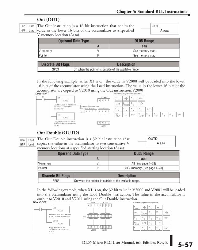
DL05 Micro PLC User Manual, 6th Edition, Rev. E 5-57
Chapter 5: Standard RLL Instructions
Out (OUT)The Out instruction is a 16 bit instruction that copies the value in the lower 16 bits of the accumulator to a specified V-memory location (Aaaa).
In the following example, when X1 is on, the value in V2000 will be loaded into the lower 16 bits of the accumulator using the Load instruction. The value in the lower 16 bits of the accumulator are copied to V2010 using the Out instruction.V2000
Out Double (OUTD)The Out Double instruction is a 32 bit instruction that copies the value in the accumulator to two consecutive V memory locations at a specified starting location (Aaaa).
In the following example, when X1 is on, the 32 bit value in V2000 and V2001 will be loaded into the accumulator using the Load Double instruction. The value in the accumulator is output to V2010 and V2011 using the Out Double instruction.
OUTA aaa
Operand Data Type DL05 Range ⸠⸠⸠⸠⸠⸠⸠⸠⸠⸠⸠⸠⸠⸠⸠⸠⸠⸠⸠⸠⸠⸠⸠⸠⸠⸠⸠⸠⸠⸠⸠⸠⸠⸠⸠⸠⸠⸠⸠⸠⸠⸠⸠⸠⸠⸠⸠⸠⸠⸠⸠⸠⸠⸠⸠⸠⸠⸠⸠⸠⸠⸠⸠⸠⸠⸠⸠⸠⸠⸠⸠⸠⸠A aaaV-memory ⸠⸠⸠⸠⸠⸠⸠⸠⸠⸠⸠⸠⸠⸠⸠⸠⸠⸠⸠⸠⸠⸠⸠⸠⸠⸠⸠⸠⸠⸠⸠⸠⸠⸠⸠⸠⸠⸠⸠⸠⸠⸠⸠⸠⸠⸠⸠⸠⸠⸠⸠⸠⸠⸠⸠⸠⸠⸠V See memory mapPointer ⸠⸠⸠⸠⸠⸠⸠⸠⸠⸠⸠⸠⸠⸠⸠⸠⸠⸠⸠⸠⸠⸠⸠⸠⸠⸠⸠⸠⸠⸠⸠⸠⸠⸠⸠⸠⸠⸠⸠⸠⸠⸠⸠⸠⸠⸠⸠⸠⸠⸠⸠⸠⸠⸠⸠⸠⸠⸠⸠⸠⸠⸠⸠⸠P See memory map
Operand Data Type DL05 Range ⸠⸠⸠⸠⸠⸠⸠⸠⸠⸠⸠⸠⸠⸠⸠⸠⸠⸠⸠⸠⸠⸠⸠⸠⸠⸠⸠⸠⸠⸠⸠⸠⸠⸠⸠⸠⸠⸠⸠⸠⸠⸠⸠⸠⸠⸠⸠⸠⸠⸠⸠⸠⸠⸠⸠⸠⸠⸠⸠⸠⸠⸠⸠⸠⸠⸠⸠⸠⸠⸠⸠⸠⸠A aaaV-memory ⸠⸠⸠⸠⸠⸠⸠⸠⸠⸠⸠⸠⸠⸠⸠⸠⸠⸠⸠⸠⸠⸠⸠⸠⸠⸠⸠⸠⸠⸠⸠⸠⸠⸠⸠⸠⸠⸠⸠⸠⸠⸠⸠⸠⸠⸠⸠⸠⸠⸠⸠⸠⸠⸠⸠⸠⸠⸠V All (See page 4–28)Pointer ⸠⸠⸠⸠⸠⸠⸠⸠⸠⸠⸠⸠⸠⸠⸠⸠⸠⸠⸠⸠⸠⸠⸠⸠⸠⸠⸠⸠⸠⸠⸠⸠⸠⸠⸠⸠⸠⸠⸠⸠⸠⸠⸠⸠⸠⸠⸠⸠⸠⸠⸠⸠⸠⸠⸠⸠⸠⸠⸠⸠⸠⸠⸠⸠P All V-memory (See page 4–28)
Discrete Bit Flags DescriptionSP53 On when the pointer is outside of the available range.
Discrete Bit Flags DescriptionSP53 On when the pointer is outside of the available range.
2C
0A
0A
0A ENT
1B ENT
Handheld Programmer Keystrokes
LD
V2000
X1
Load the value in V2000 intothe lower 16 bits of theaccumulator
OUT
V2010
Copy the value in the lower16 bits of the accumulator toV2010 V2010
Acc.
V2000
8 9 3 5
8 9 3 5
0 0 0 0 8 9 3 5 8 9 3 5
Direct SOFT32
The unused accumulator bits are set to zero
STR$
SHFTANDSTL
3D
OUTGX SHFT
ANDV
2C
0A
1B
0A ENT
OUTDA aaa
2C
0A
0A
0A ENT
2C
0A
1B
0A ENT
1B ENT
Handheld Programmer Keystrokes
V2010
Acc.
V2000
6 7 3 9 5 0 2 6 5 0 2 6
V2001
6 7 3 9 5 0 2 6
V2011
6 7 3 9 5 0 2 6
Load the value in V2000 andV2001 into the accumulator
LDD
OUTD
Copy the value in theaccumulator to V2010 andV2011
V2000
X1
V2010
Direct SOFT32
STR$
SHFTANDSTL
3D
3D
OUTGX SHFT
3D
DS5 Used
HPP Used
DS5 Used
HPP Used
DirectSOFT
DirectSOFT
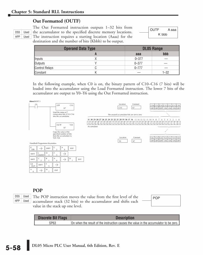
DL05 Micro PLC User Manual, 6th Edition, Rev. E5-58
Chapter 5: Standard RLL Instructions
Out Formatted (OUTF)The Out Formatted instruction outputs 1–32 bits from the accumulator to the specified discrete memory locations. The instruction requires a starting location (Aaaa) for the destination and the number of bits (Kbbb) to be output.
In the following example, when C0 is on, the binary pattern of C10–C16 (7 bits) will be loaded into the accumulator using the Load Formatted instruction. The lower 7 bits of the accumulator are output to Y0–Y6 using the Out Formatted instruction.
POPThe POP instruction moves the value from the first level of the accumulator stack (32 bits) to the accumulator and shifts each value in the stack up one level.
Discrete Bit Flags DescriptionSP63 On when the result of the instruction causes the value in the accumulator to be zero.
bbbKOUTF A aaa
Operand Data Type DL05 Range ⸠⸠⸠⸠⸠⸠⸠⸠⸠⸠⸠⸠⸠⸠⸠⸠⸠⸠⸠⸠⸠⸠⸠⸠⸠⸠⸠⸠⸠⸠⸠⸠⸠⸠⸠⸠⸠⸠⸠⸠⸠⸠⸠⸠⸠⸠⸠⸠⸠⸠⸠⸠⸠⸠⸠⸠⸠⸠⸠⸠⸠⸠⸠⸠⸠⸠⸠⸠⸠⸠⸠⸠⸠A aaa bbbInputs ⸠⸠⸠⸠⸠⸠⸠⸠⸠⸠⸠⸠⸠⸠⸠⸠⸠⸠⸠⸠⸠⸠⸠⸠⸠⸠⸠⸠⸠⸠⸠⸠⸠⸠⸠⸠⸠⸠⸠⸠⸠⸠⸠⸠⸠⸠⸠⸠⸠⸠⸠⸠⸠⸠⸠⸠⸠⸠⸠⸠⸠⸠⸠⸠⸠X 0–377 ––Outputs ⸠⸠⸠⸠⸠⸠⸠⸠⸠⸠⸠⸠⸠⸠⸠⸠⸠⸠⸠⸠⸠⸠⸠⸠⸠⸠⸠⸠⸠⸠⸠⸠⸠⸠⸠⸠⸠⸠⸠⸠⸠⸠⸠⸠⸠⸠⸠⸠⸠⸠⸠⸠⸠⸠⸠⸠⸠⸠⸠⸠⸠⸠⸠Y 0–377 ––Control Relays ⸠⸠⸠⸠⸠⸠⸠⸠⸠⸠⸠⸠⸠⸠⸠⸠⸠⸠⸠⸠⸠⸠⸠⸠⸠⸠⸠⸠⸠⸠⸠⸠⸠⸠⸠⸠⸠⸠⸠⸠⸠⸠⸠⸠⸠⸠⸠⸠⸠⸠⸠⸠C 0–777 ––Constant ⸠⸠⸠⸠⸠⸠⸠⸠⸠⸠⸠⸠⸠⸠⸠⸠⸠⸠⸠⸠⸠⸠⸠⸠⸠⸠⸠⸠⸠⸠⸠⸠⸠⸠⸠⸠⸠⸠⸠⸠⸠⸠⸠⸠⸠⸠⸠⸠⸠⸠⸠⸠⸠⸠⸠⸠⸠⸠⸠⸠⸠K –– 1–32
0A
7H ENT
Handheld Programmer Keystrokes
LDF C10
K7
C0
Load the status of 7consecutive bits (C10–C16)into the accumulator
OUTF Y20
K7
Copy the value of thespecified number of bitsfrom the accumulator toY20–Y26
K7C10
Location Constant
0 0 0 0 0 0 0 0 0 0 0 0 1 1 1 00 0 0 0 0 0 0 0 0 0 0 0 0 0 0 0
15 14 13 12 11 10 9 8 7 6 5 4 3 2 1 031 30 29 28 27 26 25 24 23 22 21 20 19 18 17 1631 30 29 28 27 26 25 24 23 22 21 20 19 18 17 16
K7Y0
Location Constant
C16 C15 C14 C13 C12 C11 C10
OFFONONONOFFOFF OFF
Y21 Y20 Y23 Y22 Y26 Y25 Y24
OFFONONONOFFOFFOFF
The unused accumulator bits are set to zero
Accumulator
DirectSOFT 5
STR$ SHFT ENT
2C
0A
SHFTANDSTL
3D
5F
SHFT2
C1
B0
A7
H ENT
OUTGX SHFT
5F
POPDS5 Used
HPP Used
DS5 Used
HPP Used
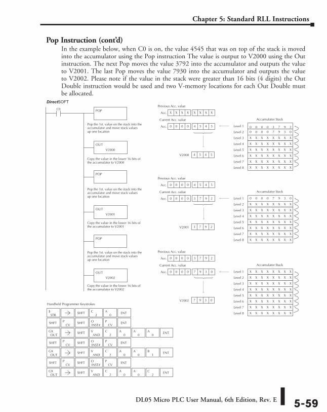
DL05 Micro PLC User Manual, 6th Edition, Rev. E 5-59
Chapter 5: Standard RLL Instructions
Pop Instruction (cont’d)In the example below, when C0 is on, the value 4545 that was on top of the stack is moved into the accumulator using the Pop instruction The value is output to V2000 using the Out instruction. The next Pop moves the value 3792 into the accumulator and outputs the value to V2001. The last Pop moves the value 7930 into the accumulator and outputs the value to V2002. Please note if the value in the stack were greater than 16 bits (4 digits) the Out Double instruction would be used and two V-memory locations for each Out Double must be allocated.
Handheld Programmer Keystrokes
Acc.
Pop the 1st. value on the stack into theaccumulator and move stack valuesup one location
POPC0
POP
POP
V2000 4 5 4 5
X X X X X X X X X X X X
Acc. 0 0 0 0 4 5 4 5 4 5 4 5
Previous Acc. value
Current Acc. value
0 0 0 0 3 7 9 2 0 0
Level 1
0 0 0 0 7 9 3 0 Level 2
X X X X X X X X Level 3
X X X X X X X X Level 4
X X X X X X X X Level 5
X X X X X X X X Level 6
X X X X X X X X Level 7
X X X X X X X X Level 8
Accumulator Stack
0 0 0 0 7 9 3 0 Level 1
X X X X X X X X Level 2
X X X X X X X X Level 3
X X X X X X X X Level 4
X X X X X X X X Level 5
X X X X X X X X Level 6
X X X X X X X X Level 7
X X X X X X X X Level 8
Accumulator Stack
X X X X X X X X Level 1
X X X X X X X X Level 2
X X X X X X X X Level 3
X X X X X X X X Level 4
X X X X X X X X Level 5
X X X X X X X X Level 6
X X X X X X X X Level 7
X X X X X X X X Level 8
Accumulator Stack
Pop the 1st. value on the stack into theaccumulator and move stack valuesup one location
Pop the 1st. value on the stack into theaccumulator and move stack valuesup one location
OUT
V2000
OUT
V2001
Acc.
V2001 3 7 9 2
0 0 0 0 4 5 4 5 4 5 4 5
Acc. 0 0 0 0 3 7 9 2
Previous Acc. value
Current Acc. value
Acc.
V2002 7 9 3 0
0 0 0 0 3 7 9 2
Acc. 0 0 0 0 7 9 3 0
Previous Acc. value
Current Acc. value
OUT
V2002
Copy the value in the lower 16 bits ofthe accumulator to V2000
Copy the value in the lower 16 bits ofthe accumulator to V2001
Copy the value in the lower 16 bits ofthe accumulator to V2002
Direct SOFT32
STR$ SHFT
2C
0A ENT
SHFTCV
PINST#O
CVP ENT
OUTGX SHFT
ANDV
2C
0A
0A ENT
0A
SHFTCV
PINST#O
CVP ENT
OUTGX SHFT
ANDV
2C
0A ENT
0A
1B
SHFTCV
PINST#O
CVP ENT
OUTGX SHFT
ANDV
2C
0A ENT
0A
2C
SHFT
SHFT
SHFT
DirectSOFT
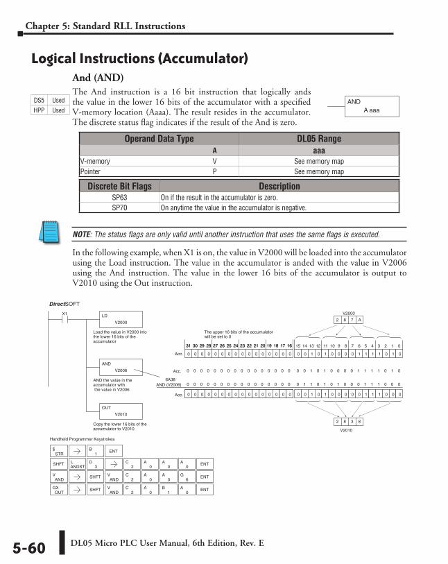
DL05 Micro PLC User Manual, 6th Edition, Rev. E5-60
Chapter 5: Standard RLL Instructions
Logical Instructions (Accumulator)And (AND)The And instruction is a 16 bit instruction that logically ands the value in the lower 16 bits of the accumulator with a specified V-memory location (Aaaa). The result resides in the accumulator. The discrete status flag indicates if the result of the And is zero.
NOTE: The status flags are only valid until another instruction that uses the same flags is executed.
In the following example, when X1 is on, the value in V2000 will be loaded into the accumulator using the Load instruction. The value in the accumulator is anded with the value in V2006 using the And instruction. The value in the lower 16 bits of the accumulator is output to V2010 using the Out instruction.
ANDA aaa
AND (V2006)
Handheld Programmer Keystrokes
LD
V2000
X1
Load the value in V2000 intothe lower 16 bits of theaccumulator
AND
V2006
AND the value in theaccumulator with the value in V2006
OUT
V2010
Copy the lower 16 bits of theaccumulator to V2010
0 0 1 0 1 0 0 0 0 1 1 1 1 0 1 0
0 0 1 0 1 0 0 0 0 0 1 1 1 0 0 00 0 0 0 0 1 0 0 0 0 0 0 0 0 0 0
V2000
2 8 7 A
0 0 0 0 0 0 0 0 0 0 0 0 0 0 0 0
0 0 0 0 0 0 0 0 0 0 0 0 0 0 0 0
The upper 16 bits of the accumulatorwill be set to 0
15 14 13 12 11 10 9 8 7 6 5 4 3 2 1 031 30 29 28 27 26 25 24 23 22 21 20 19 18 17 1631 30 29 28 27 26 25 24 23 22 21 20 19 18 17 16
Acc.
Acc.
0 0 1 0 1 0 0 0 0 1 1 1 1 0 1 00 0 0 0 0 0 0 0 0 0 0 0 0 0 0 0Acc.
0 1 1 0 1 0 1 0 0 0 1 1 1 0 0 00 0 0 0 0 0 0 0 0 0 0 0 0 0 0 06A38
V2010
2 8 3 8
Direct SOFT32
STR$
SHFTANDSTL
3D
SHFTAND
V2
C0
A0
A ENT6
G
OUTGX SHFT
ANDV
2C
0A
1B
0A ENT
ANDV
1B ENT
2C
0A
0A
0A ENT
Operand Data Type DL05 Range ⸠⸠⸠⸠⸠⸠⸠⸠⸠⸠⸠⸠⸠⸠⸠⸠⸠⸠⸠⸠⸠⸠⸠⸠⸠⸠⸠⸠⸠⸠⸠⸠⸠⸠⸠⸠⸠⸠⸠⸠⸠⸠⸠⸠⸠⸠⸠⸠⸠⸠⸠⸠⸠⸠⸠⸠⸠⸠⸠⸠⸠⸠⸠⸠⸠⸠⸠⸠⸠⸠⸠⸠⸠A aaaV-memory ⸠⸠⸠⸠⸠⸠⸠⸠⸠⸠⸠⸠⸠⸠⸠⸠⸠⸠⸠⸠⸠⸠⸠⸠⸠⸠⸠⸠⸠⸠⸠⸠⸠⸠⸠⸠⸠⸠⸠⸠⸠⸠⸠⸠⸠⸠⸠⸠⸠⸠⸠⸠⸠⸠⸠⸠⸠⸠V See memory mapPointer ⸠⸠⸠⸠⸠⸠⸠⸠⸠⸠⸠⸠⸠⸠⸠⸠⸠⸠⸠⸠⸠⸠⸠⸠⸠⸠⸠⸠⸠⸠⸠⸠⸠⸠⸠⸠⸠⸠⸠⸠⸠⸠⸠⸠⸠⸠⸠⸠⸠⸠⸠⸠⸠⸠⸠⸠⸠⸠⸠⸠⸠⸠⸠⸠P See memory map
Discrete Bit Flags DescriptionSP63 On if the result in the accumulator is zero.SP70 On anytime the value in the accumulator is negative.
DS5 Used
HPP Used
DirectSOFT
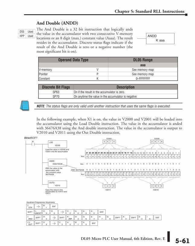
DL05 Micro PLC User Manual, 6th Edition, Rev. E 5-61
Chapter 5: Standard RLL Instructions
And Double (ANDD)The And Double is a 32 bit instruction that logically ands the value in the accumulator with two consecutive V-memory locations or an 8 digit (max.) constant value (Aaaa). The result resides in the accumulator. Discrete status flags indicate if the result of the And Double is zero or a negative number (the most significant bit is on).
In the following example, when X1 is on, the value in V2000 and V2001 will be loaded into the accumulator using the Load Double instruction. The value in the accumulator is anded with 36476A38 using the And double instruction. The value in the accumulator is output to V2010 and V2011 using the Out Double instruction.
K aaaANDD
AND 36476A38
Handheld Programmer Keystrokes
LDD
V2000
X1
Load the value in V2000 andV2001 into the accumulator
ANDD
K36476A38
AND the value in theaccumulator with the constant value36476A38
OUTD
V2010
Copy the value in theaccumulator to V2010 andV2011
0 0 1 0 1 0 0 0 0 1 1 1 1 0 1 0
0 0 1 0 1 0 0 0 0 0 1 1 1 0 0 00 0 0 0 0 1 0 0 0 0 0 0 0 0 0 0
2 8 7 A
0 0 0 1 0 1 0 0 0 1 0 0 0 1 1 0
0 1 0 1 0 1 0 0 0 1 1 1 1 1 1 0
15 14 13 12 11 10 9 8 7 6 5 4 3 2 1 031 30 29 28 27 26 25 24 23 22 21 20 19 18 17 1631 30 29 28 27 26 25 24 23 22 21 20 19 18 17 16
Acc.
Acc.
Acc.
V2010
2 8 3 8
5 4 7 E
V2011
1 4 4 6
0 1 0 1 0 1 0 0 0 1 1 1 1 1 1 0 0 0 1 0 1 0 0 0 0 1 1 1 1 0 1 0
0 1 1 0 1 0 1 0 0 0 1 1 1 0 0 00 0 1 1 0 1 1 0 0 1 0 0 0 1 1 1
Direct SOFT32
STR$
SHFTANDSTL
3D
SHFT
OUTGX
3D
SHFT3
D
ANDV SHFT
3D
8I
3DSHFTSHFT
JMPK
0A
3D
6G
4E
7H
6G ENT
1B ENT
2C
0A
1B
0A ENT
2C
0A
0A ENT
0A
V2000 V2000
Operand Data Type DL05 Rangeaaa
V-memory ⸠⸠⸠⸠⸠⸠⸠⸠⸠⸠⸠⸠⸠⸠⸠⸠⸠⸠⸠⸠⸠⸠⸠⸠⸠⸠⸠⸠⸠⸠⸠⸠⸠⸠⸠⸠⸠⸠⸠⸠⸠⸠⸠⸠⸠⸠⸠⸠⸠⸠⸠⸠⸠⸠⸠⸠⸠⸠V See memory mapPointer ⸠⸠⸠⸠⸠⸠⸠⸠⸠⸠⸠⸠⸠⸠⸠⸠⸠⸠⸠⸠⸠⸠⸠⸠⸠⸠⸠⸠⸠⸠⸠⸠⸠⸠⸠⸠⸠⸠⸠⸠⸠⸠⸠⸠⸠⸠⸠⸠⸠⸠⸠⸠⸠⸠⸠⸠⸠⸠⸠⸠⸠⸠⸠⸠P See memory mapConstant ⸠⸠⸠⸠⸠⸠⸠⸠⸠⸠⸠⸠⸠⸠⸠⸠⸠⸠⸠⸠⸠⸠⸠⸠⸠⸠⸠⸠⸠⸠⸠⸠⸠⸠⸠⸠⸠⸠⸠⸠⸠⸠⸠⸠⸠⸠⸠⸠⸠⸠⸠⸠⸠⸠⸠⸠⸠⸠⸠⸠⸠K 0–FFFFFFFF
Discrete Bit Flags DescriptionSP63 On if the result in the accumulator is zero.SP70 On anytime the value in the accumulator is negative
DS5 Used
HPP Used
DirectSOFT
NOTE: The status flags are only valid until another instruction that uses the same flags is executed.
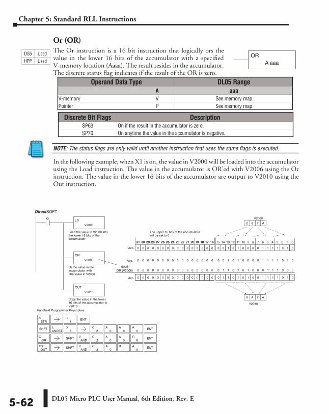
DL05 Micro PLC User Manual, 6th Edition, Rev. E5-62
Chapter 5: Standard RLL Instructions
Or (OR)The Or instruction is a 16 bit instruction that logically ors the value in the lower 16 bits of the accumulator with a specified V-memory location (Aaaa). The result resides in the accumulator. The discrete status flag indicates if the result of the OR is zero.
NOTE: The status flags are only valid until another instruction that uses the same flags is executed.
In the following example, when X1 is on, the value in V2000 will be loaded into the accumulator using the Load instruction. The value in the accumulator is OR’ed with V2006 using the Or instruction. The value in the lower 16 bits of the accumulator are output to V2010 using the Out instruction.
ORA aaa
3D
OR (V2006)
Handheld Programmer Keystrokes
LD
V2000
X1
Load the value in V2000 intothe lower 16 bits of theaccumulator
OR
V2006
Or the value in theaccumulator with the value in V2006
OUT
V2010
Copy the value in the lower16 bits of the accumulator toV2010
0 0 1 0 1 0 0 0 0 1 1 1 1 0 1 0
0 1 1 0 1 0 1 0 0 1 1 1 1 0 1 00 0 0 0 0 1 0 0 0 0 0 0 0 0 0 0
V2000
2 8 7 A
0 0 0 0 0 0 0 0 0 0 0 0 0 0 0 0
0 0 0 0 0 0 0 0 0 0 0 0 0 0 0 0
The upper 16 bits of the accumulatorwill be set to 0
15 14 13 12 11 10 9 8 7 6 5 4 3 2 131 30 29 28 27 26 25 24 23 22 21 20 19 18 17 1631 30 29 28 27 26 25 24 23 22 21 20 19 18 17 16
Acc.
Acc.
0 0 1 0 1 0 0 0 0 1 1 1 1 0 1 00 0 0 0 0 0 0 0 0 0 0 0 0 0 0 0Acc.
0 1 1 0 1 0 1 0 0 0 1 1 1 0 0 00 0 0 0 0 0 0 0 0 0 0 0 0 0 0 06A38
V2010
6 A 7 A
Direct SOFT32
STR$
1B ENT
SHFTANDSTL
2C
0A
0A
0A ENT
SHFTAND
V2
C0
A0
A ENT6
G
OUTGX SHFT
ANDV
2C
0A
1B
0A ENT
ORQ
0
Operand Data Type DL05 Range ⸠⸠⸠⸠⸠⸠⸠⸠⸠⸠⸠⸠⸠⸠⸠⸠⸠⸠⸠⸠⸠⸠⸠⸠⸠⸠⸠⸠⸠⸠⸠⸠⸠⸠⸠⸠⸠⸠⸠⸠⸠⸠⸠⸠⸠⸠⸠⸠⸠⸠⸠⸠⸠⸠⸠⸠⸠⸠⸠⸠⸠⸠⸠⸠⸠⸠⸠⸠⸠⸠⸠⸠⸠A aaaV-memory ⸠⸠⸠⸠⸠⸠⸠⸠⸠⸠⸠⸠⸠⸠⸠⸠⸠⸠⸠⸠⸠⸠⸠⸠⸠⸠⸠⸠⸠⸠⸠⸠⸠⸠⸠⸠⸠⸠⸠⸠⸠⸠⸠⸠⸠⸠⸠⸠⸠⸠⸠⸠⸠⸠⸠⸠⸠⸠V See memory mapPointer ⸠⸠⸠⸠⸠⸠⸠⸠⸠⸠⸠⸠⸠⸠⸠⸠⸠⸠⸠⸠⸠⸠⸠⸠⸠⸠⸠⸠⸠⸠⸠⸠⸠⸠⸠⸠⸠⸠⸠⸠⸠⸠⸠⸠⸠⸠⸠⸠⸠⸠⸠⸠⸠⸠⸠⸠⸠⸠⸠⸠⸠⸠⸠⸠P See memory map
Discrete Bit Flags DescriptionSP63 On if the result in the accumulator is zero.SP70 On anytime the value in the accumulator is negative.
DS5 Used
HPP Used
DirectSOFT
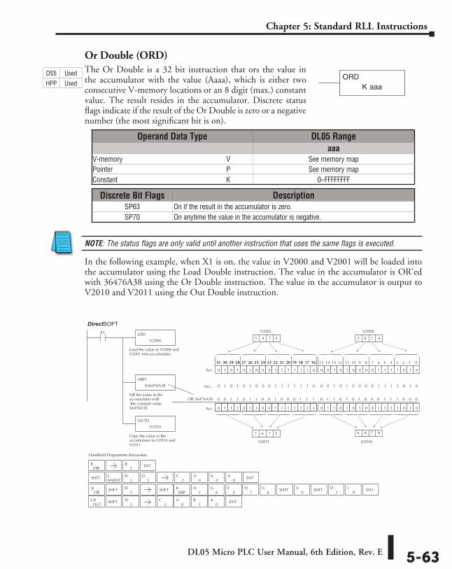
DL05 Micro PLC User Manual, 6th Edition, Rev. E 5-63
Chapter 5: Standard RLL Instructions
Or Double (ORD)The Or Double is a 32 bit instruction that ors the value in the accumulator with the value (Aaaa), which is either two consecutive V-memory locations or an 8 digit (max.) constant value. The result resides in the accumulator. Discrete status flags indicate if the result of the Or Double is zero or a negative number (the most significant bit is on).
NOTE: The status flags are only valid until another instruction that uses the same flags is executed.
In the following example, when X1 is on, the value in V2000 and V2001 will be loaded into the accumulator using the Load Double instruction. The value in the accumulator is OR’ed with 36476A38 using the Or Double instruction. The value in the accumulator is output to V2010 and V2011 using the Out Double instruction.
K aaaORD
JMPK
OR 36476A38
Handheld Programmer Keystrokes
LDD
V2000
X1
Load the value in V2000 andV2001 into accumulator
ORD
K36476A38
OR the value in theaccumulator with the constant value36476A38
OUTD
V2010
Copy the value in theaccumulator to V2010 andV2011
0 0 1 0 1 0 0 0 0 1 1 1 1 0 1 0
0 1 1 0 1 0 1 0 0 1 1 1 1 0 1 00 0 0 0 0 1 0 0 0 0 0 0 0 0 0 0
2 8 7 A
0 1 1 1 0 1 1 0 0 1 1 1 1 1 1 1
0 1 0 1 0 1 0 0 0 1 1 1 1 1 1 0
15 14 13 12 11 10 9 8 7 6 5 4 3 2 1 031 30 29 28 27 26 25 24 23 22 21 20 19 18 17 1631 30 29 28 27 26 25 24 23 22 21 20 19 18 17 16
Acc.
Acc.
Acc.
V2010
6 A 7 A
5 4 7 E
V2011
7 6 7 F
0 1 0 1 0 1 0 0 0 1 1 1 1 1 1 0 0 0 1 0 1 0 0 0 0 1 1 1 1 0 1 0
Direct SOFT32
0 1 1 0 1 0 1 0 0 0 1 1 1 0 0 00 0 1 1 0 1 1 0 0 1 0 0 0 1 1 1
STR$
SHFTANDSTL
3D
SHFT
OUTGX
3D
SHFT3
D
SHFT3
DOR
Q8
I3
DSHFTSHFT0
A3
D6
G4
E7
H6
G ENT
1B ENT
2C
0A
0A
0A ENT
2C
0A
1B
0A ENT
V2000V2001
Operand Data Type DL05 Rangeaaa
V-memory ⸠⸠⸠⸠⸠⸠⸠⸠⸠⸠⸠⸠⸠⸠⸠⸠⸠⸠⸠⸠⸠⸠⸠⸠⸠⸠⸠⸠⸠⸠⸠⸠⸠⸠⸠⸠⸠⸠⸠⸠⸠⸠⸠⸠⸠⸠⸠⸠⸠⸠⸠⸠⸠⸠⸠⸠⸠⸠V See memory mapPointer ⸠⸠⸠⸠⸠⸠⸠⸠⸠⸠⸠⸠⸠⸠⸠⸠⸠⸠⸠⸠⸠⸠⸠⸠⸠⸠⸠⸠⸠⸠⸠⸠⸠⸠⸠⸠⸠⸠⸠⸠⸠⸠⸠⸠⸠⸠⸠⸠⸠⸠⸠⸠⸠⸠⸠⸠⸠⸠⸠⸠⸠⸠⸠⸠P See memory mapConstant ⸠⸠⸠⸠⸠⸠⸠⸠⸠⸠⸠⸠⸠⸠⸠⸠⸠⸠⸠⸠⸠⸠⸠⸠⸠⸠⸠⸠⸠⸠⸠⸠⸠⸠⸠⸠⸠⸠⸠⸠⸠⸠⸠⸠⸠⸠⸠⸠⸠⸠⸠⸠⸠⸠⸠⸠⸠⸠⸠⸠⸠K 0–FFFFFFFF
Discrete Bit Flags DescriptionSP63 On if the result in the accumulator is zero.SP70 On anytime the value in the accumulator is negative.
DS5 Used
HPP Used
DirectSOFT
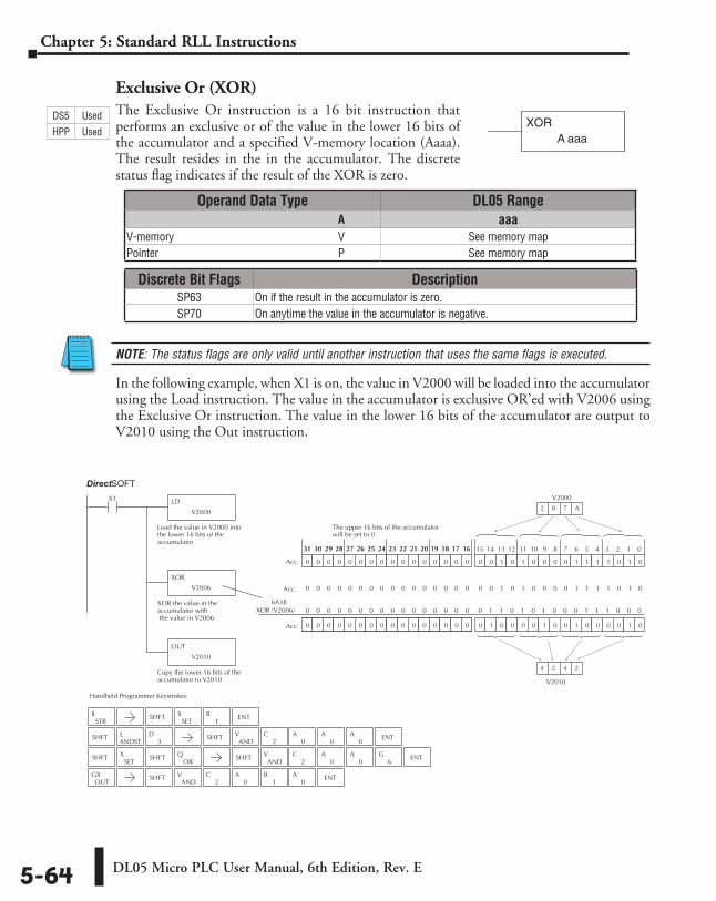
DL05 Micro PLC User Manual, 6th Edition, Rev. E5-64
Chapter 5: Standard RLL Instructions
Exclusive Or (XOR)The Exclusive Or instruction is a 16 bit instruction that performs an exclusive or of the value in the lower 16 bits of the accumulator and a specified V-memory location (Aaaa). The result resides in the in the accumulator. The discrete status flag indicates if the result of the XOR is zero.
NOTE: The status flags are only valid until another instruction that uses the same flags is executed.
In the following example, when X1 is on, the value in V2000 will be loaded into the accumulator using the Load instruction. The value in the accumulator is exclusive OR’ed with V2006 using the Exclusive Or instruction. The value in the lower 16 bits of the accumulator are output to V2010 using the Out instruction.
XORA aaa
XOR (V2006)
Handheld Programmer Keystrokes
LD
V2000
X1
Load the value in V2000 intothe lower 16 bits of theaccumulator
XOR
V2006
XOR the value in theaccumulator with the value in V2006
OUT
V2010
Copy the lower 16 bits of theaccumulator to V2010
0 0 1 0 1 0 0 0 0 1 1 1 1 0 1 0
0 1 0 0 0 0 1 0 0 1 0 0 0 0 1 00 0 0 0 0 1 0 0 0 0 0 0 0 0 0 0
V2000
2 8 7 A
0 0 0 0 0 0 0 0 0 0 0 0 0 0 0 0
0 0 0 0 0 0 0 0 0 0 0 0 0 0 0 0
The upper 16 bits of the accumulatorwill be set to 0
15 14 13 12 11 10 9 8 7 6 5 4 3 2 1 031 30 29 28 27 26 25 24 23 22 21 20 19 18 17 1631 30 29 28 27 26 25 24 23 22 21 20 19 18 17 16
Acc.
Acc.
0 0 1 0 1 0 0 0 0 1 1 1 1 0 1 00 0 0 0 0 0 0 0 0 0 0 0 0 0 0 0Acc.
6A38
V2010
4 2 4 2
Direct SOFT32
0 1 1 0 1 0 1 0 0 0 1 1 1 0 0 00 0 0 0 0 0 0 0 0 0 0 0 0 0 0 0
STR$ SHFT
SETX
1B ENT
SHFTANDSTL
3D SHFT
ANDV
2C
0A
0A
0A ENT
SHFTAND
V2
C0
A0
A ENT6
G
OUTGX SHFT
ANDV
2C
0A
1B
0A ENT
ORQSHFT SHFT
SETX
Operand Data Type DL05 Range ⸠⸠⸠⸠⸠⸠⸠⸠⸠⸠⸠⸠⸠⸠⸠⸠⸠⸠⸠⸠⸠⸠⸠⸠⸠⸠⸠⸠⸠⸠⸠⸠⸠⸠⸠⸠⸠⸠⸠⸠⸠⸠⸠⸠⸠⸠⸠⸠⸠⸠⸠⸠⸠⸠⸠⸠⸠⸠⸠⸠⸠⸠⸠⸠⸠⸠⸠⸠⸠⸠⸠⸠⸠A aaaV-memory ⸠⸠⸠⸠⸠⸠⸠⸠⸠⸠⸠⸠⸠⸠⸠⸠⸠⸠⸠⸠⸠⸠⸠⸠⸠⸠⸠⸠⸠⸠⸠⸠⸠⸠⸠⸠⸠⸠⸠⸠⸠⸠⸠⸠⸠⸠⸠⸠⸠⸠⸠⸠⸠⸠⸠⸠⸠⸠V See memory mapPointer ⸠⸠⸠⸠⸠⸠⸠⸠⸠⸠⸠⸠⸠⸠⸠⸠⸠⸠⸠⸠⸠⸠⸠⸠⸠⸠⸠⸠⸠⸠⸠⸠⸠⸠⸠⸠⸠⸠⸠⸠⸠⸠⸠⸠⸠⸠⸠⸠⸠⸠⸠⸠⸠⸠⸠⸠⸠⸠⸠⸠⸠⸠⸠⸠P See memory map
DS5 Used
HPP Used
Discrete Bit Flags DescriptionSP63 On if the result in the accumulator is zero.SP70 On anytime the value in the accumulator is negative.
DirectSOFT
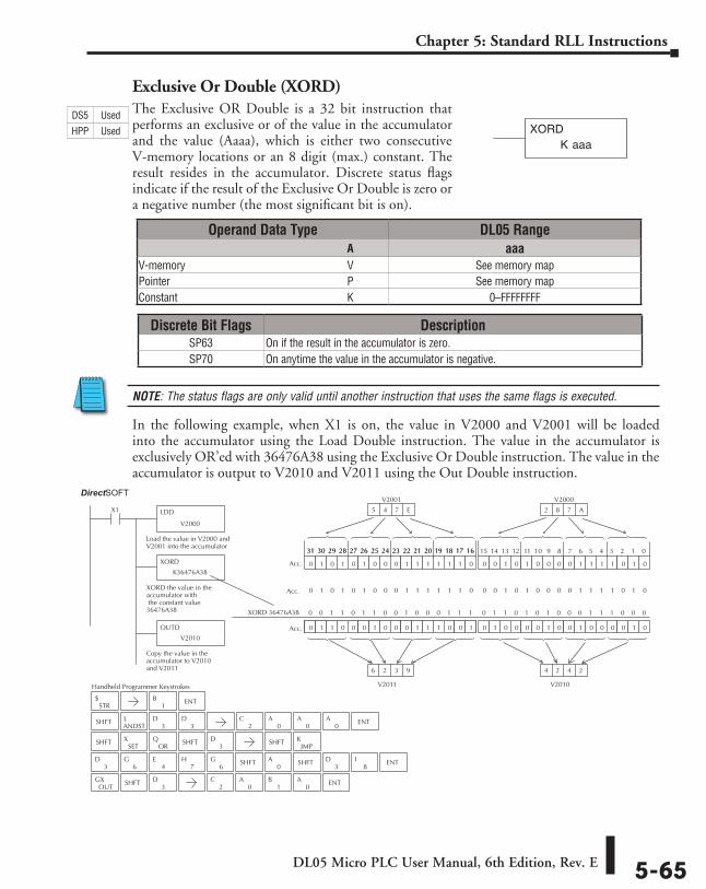
DL05 Micro PLC User Manual, 6th Edition, Rev. E 5-65
Chapter 5: Standard RLL Instructions
Exclusive Or Double (XORD)The Exclusive OR Double is a 32 bit instruction that performs an exclusive or of the value in the accumulator and the value (Aaaa), which is either two consecutive V-memory locations or an 8 digit (max.) constant. The result resides in the accumulator. Discrete status flags indicate if the result of the Exclusive Or Double is zero or a negative number (the most significant bit is on).
NOTE: The status flags are only valid until another instruction that uses the same flags is executed.
In the following example, when X1 is on, the value in V2000 and V2001 will be loaded into the accumulator using the Load Double instruction. The value in the accumulator is exclusively OR’ed with 36476A38 using the Exclusive Or Double instruction. The value in the accumulator is output to V2010 and V2011 using the Out Double instruction.
K aaaXORD
JMPKSHFTSHFT
3D
ORQ
XORD 36476A38
Handheld Programmer Keystrokes
LDD
V2000
X1
Load the value in V2000 andV2001 into the accumulator
XORD
K36476A38
XORD the value in theaccumulator with the constant value36476A38
OUTD
V2010
Copy the value in theaccumulator to V2010and V2011
0 0 1 0 1 0 0 0 0 1 1 1 1 0 1 0
0 1 0 0 0 0 1 0 0 1 0 0 0 0 1 00 0 0 0 0 1 0 0 0 0 0 0 0 0 0 0
V2000
2 8 7 A
0 1 1 0 0 0 1 0 0 0 1 1 1 0 0 1
0 1 0 1 0 1 0 0 0 1 1 1 1 1 1 0
15 14 13 12 11 10 9 8 7 6 5 4 3 2 1 031 30 29 28 27 26 25 24 23 22 21 20 19 18 17 1631 30 29 28 27 26 25 24 23 22 21 20 19 18 17 16
Acc.
Acc.
Acc.
V2010
4 2 4 2
V2001
5 4 7 E
V2011
6 2 3 9
0 1 0 1 0 1 0 0 0 1 1 1 1 1 1 0 0 0 1 0 1 0 0 0 0 1 1 1 1 0 1 0
Direct SOFT32
0 1 1 0 1 0 1 0 0 0 1 1 1 0 0 00 0 1 1 0 1 1 0 0 1 0 0 0 1 1 1
STR$
SHFTANDSTL
3D
3D
SHFTSET
X
OUTGX SHFT
3D
3D
6G
4E
8I
3DSHFTSHFT
0A
7H
6G ENT
1B ENT
2C
0A
0A
0A ENT
2C
0A
1B
0A ENT
Operand Data Type DL05 Range ⸠⸠⸠⸠⸠⸠⸠⸠⸠⸠⸠⸠⸠⸠⸠⸠⸠⸠⸠⸠⸠⸠⸠⸠⸠⸠⸠⸠⸠⸠⸠⸠⸠⸠⸠⸠⸠⸠⸠⸠⸠⸠⸠⸠⸠⸠⸠⸠⸠⸠⸠⸠⸠⸠⸠⸠⸠⸠⸠⸠⸠⸠⸠⸠⸠⸠⸠⸠⸠⸠⸠⸠⸠A aaaV-memory ⸠⸠⸠⸠⸠⸠⸠⸠⸠⸠⸠⸠⸠⸠⸠⸠⸠⸠⸠⸠⸠⸠⸠⸠⸠⸠⸠⸠⸠⸠⸠⸠⸠⸠⸠⸠⸠⸠⸠⸠⸠⸠⸠⸠⸠⸠⸠⸠⸠⸠⸠⸠⸠⸠⸠⸠⸠⸠V See memory mapPointer ⸠⸠⸠⸠⸠⸠⸠⸠⸠⸠⸠⸠⸠⸠⸠⸠⸠⸠⸠⸠⸠⸠⸠⸠⸠⸠⸠⸠⸠⸠⸠⸠⸠⸠⸠⸠⸠⸠⸠⸠⸠⸠⸠⸠⸠⸠⸠⸠⸠⸠⸠⸠⸠⸠⸠⸠⸠⸠⸠⸠⸠⸠⸠⸠P See memory mapConstant ⸠⸠⸠⸠⸠⸠⸠⸠⸠⸠⸠⸠⸠⸠⸠⸠⸠⸠⸠⸠⸠⸠⸠⸠⸠⸠⸠⸠⸠⸠⸠⸠⸠⸠⸠⸠⸠⸠⸠⸠⸠⸠⸠⸠⸠⸠⸠⸠⸠⸠⸠⸠⸠⸠⸠⸠⸠⸠⸠⸠⸠K 0–FFFFFFFF
DS5 Used
HPP Used
Discrete Bit Flags DescriptionSP63 On if the result in the accumulator is zero.SP70 On anytime the value in the accumulator is negative.
DirectSOFT
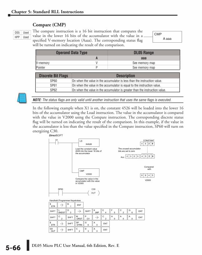
DL05 Micro PLC User Manual, 6th Edition, Rev. E5-66
Chapter 5: Standard RLL Instructions
Compare (CMP)The compare instruction is a 16 bit instruction that compares the value in the lower 16 bits of the accumulator with the value in a specified V-memory location (Aaaa). The corresponding status flag will be turned on indicating the result of the comparison.
NOTE: The status flags are only valid until another instruction that uses the same flags is executed.
In the following example when X1 is on, the constant 4526 will be loaded into the lower 16 bits of the accumulator using the Load instruction. The value in the accumulator is compared with the value in V2000 using the Compare instruction. The corresponding discrete status flag will be turned on indicating the result of the comparison. In this example, if the value in the accumulator is less than the value specified in the Compare instruction, SP60 will turn on energizing C30.
CMPA aaa
Discrete Bit Flags DescriptionSP60 On when the value in the accumulator is less than the instruction value.SP61 On when the value in the accumulator is equal to the instruction value.SP62 On when the value in the accumulator is greater than the instruction value.
Handheld Programmer Keystrokes
V2000
Acc.
CONSTANT4 5 2 6 ? ?
8 9 4 5
0 0 0 0 4 5 2 64 5 2 6 ? ?
LD
Compare the value in theaccumulator with the valuein V2000
Load the constant value4526 into the lower 16 bits ofthe accumulator
K4526
CMP
X1
V2000
Compared with
SP60 C30
DirectSOFT32
The unused accumulatorbits are set to zero
STR$
SHFT ANDSTL
3D SHFT JMP
K4
E5
F2
C6
G ENT
SHFT 2C
ORSTM
CVP
STR$ SHFT ENTSTRN
SP6
G0
A
OUTGX SHFT 2
C3
D0
A ENT
1B ENT
2C
0A
0A
0A ENTSHFT
OUT
Operand Data Type DL05 Range ⸠⸠⸠⸠⸠⸠⸠⸠⸠⸠⸠⸠⸠⸠⸠⸠⸠⸠⸠⸠⸠⸠⸠⸠⸠⸠⸠⸠⸠⸠⸠⸠⸠⸠⸠⸠⸠⸠⸠⸠⸠⸠⸠⸠⸠⸠⸠⸠⸠⸠⸠⸠⸠⸠⸠⸠⸠⸠⸠⸠⸠⸠⸠⸠⸠⸠⸠⸠⸠⸠⸠⸠⸠A aaaV-memory ⸠⸠⸠⸠⸠⸠⸠⸠⸠⸠⸠⸠⸠⸠⸠⸠⸠⸠⸠⸠⸠⸠⸠⸠⸠⸠⸠⸠⸠⸠⸠⸠⸠⸠⸠⸠⸠⸠⸠⸠⸠⸠⸠⸠⸠⸠⸠⸠⸠⸠⸠⸠⸠⸠⸠⸠⸠⸠V See memory mapPointer ⸠⸠⸠⸠⸠⸠⸠⸠⸠⸠⸠⸠⸠⸠⸠⸠⸠⸠⸠⸠⸠⸠⸠⸠⸠⸠⸠⸠⸠⸠⸠⸠⸠⸠⸠⸠⸠⸠⸠⸠⸠⸠⸠⸠⸠⸠⸠⸠⸠⸠⸠⸠⸠⸠⸠⸠⸠⸠⸠⸠⸠⸠⸠⸠P See memory map
DS5 Used
HPP Used
DirectSOFT
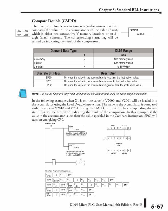
DL05 Micro PLC User Manual, 6th Edition, Rev. E 5-67
Chapter 5: Standard RLL Instructions
Compare Double (CMPD)The Compare Double instruction is a 32–bit instruction that compares the value in the accumulator with the value (Aaaa), which is either two consecutive V-memory locations or an 8–digit (max.) constant. The corresponding status flag will be turned on indicating the result of the comparison.
NOTE: The status flags are only valid until another instruction that uses the same flags is executed.
In the following example when X1 is on, the value in V2000 and V2001 will be loaded into the accumulator using the Load Double instruction. The value in the accumulator is compared with the value in V2010 and V2011 using the CMPD instruction. The corresponding discrete status flag will be turned on indicating the result of the comparison. In this example, if the value in the accumulator is less than the value specified in the Compare instruction, SP60 will turn on energizing C30.
CMPDA aaa
Handheld Programmer Keystrokes
LDD
Compare the value in theaccumulator with the valuein V2010 and V2011
Load the value in V2000 andV2001 into the accumulator
V2000
CMPD
X1
V2010
Compared with
SP60 C30
V2010
Acc.
V2000
4 5 2 6 7 7 ? 7 2 9 9
V20014 5 2 6 7 2 9 9
V20116 7 3 9 5 0 2 6
DirectSOFT32
STR$
SHFT ANDSTL
3D
SHFT 2C
ORSTM
CVP
STR$ SHFT ENTSTRN
SP6
G0
A
OUTGX SHFT 2
C3
D0
A ENT
3D
3D
1B ENT
ENT
2C
0A
0A ENT
2C
0A
0A
0A
1BSHFT
OUT
Operand Data Type DL05 Range ⸠⸠⸠⸠⸠⸠⸠⸠⸠⸠⸠⸠⸠⸠⸠⸠⸠⸠⸠⸠⸠⸠⸠⸠⸠⸠⸠⸠⸠⸠⸠⸠⸠⸠⸠⸠⸠⸠⸠⸠⸠⸠⸠⸠⸠⸠⸠⸠⸠⸠⸠⸠⸠⸠⸠⸠⸠⸠⸠⸠⸠⸠⸠⸠⸠⸠⸠⸠⸠⸠⸠⸠⸠A aaaV-memory ⸠⸠⸠⸠⸠⸠⸠⸠⸠⸠⸠⸠⸠⸠⸠⸠⸠⸠⸠⸠⸠⸠⸠⸠⸠⸠⸠⸠⸠⸠⸠⸠⸠⸠⸠⸠⸠⸠⸠⸠⸠⸠⸠⸠⸠⸠⸠⸠⸠⸠⸠⸠⸠⸠⸠⸠⸠⸠V See memory mapPointer ⸠⸠⸠⸠⸠⸠⸠⸠⸠⸠⸠⸠⸠⸠⸠⸠⸠⸠⸠⸠⸠⸠⸠⸠⸠⸠⸠⸠⸠⸠⸠⸠⸠⸠⸠⸠⸠⸠⸠⸠⸠⸠⸠⸠⸠⸠⸠⸠⸠⸠⸠⸠⸠⸠⸠⸠⸠⸠⸠⸠⸠⸠⸠⸠P See memory mapConstant ⸠⸠⸠⸠⸠⸠⸠⸠⸠⸠⸠⸠⸠⸠⸠⸠⸠⸠⸠⸠⸠⸠⸠⸠⸠⸠⸠⸠⸠⸠⸠⸠⸠⸠⸠⸠⸠⸠⸠⸠⸠⸠⸠⸠⸠⸠⸠⸠⸠⸠⸠⸠⸠⸠⸠⸠⸠⸠⸠⸠⸠K 0–FFFFFFFF
Discrete Bit Flags DescriptionSP60 On when the value in the accumulator is less than the instruction value.SP61 On when the value in the accumulator is equal to the instruction value.SP62 On when the value in the accumulator is greater than the instruction value.
DS5 Used
HPP Used
DirectSOFT
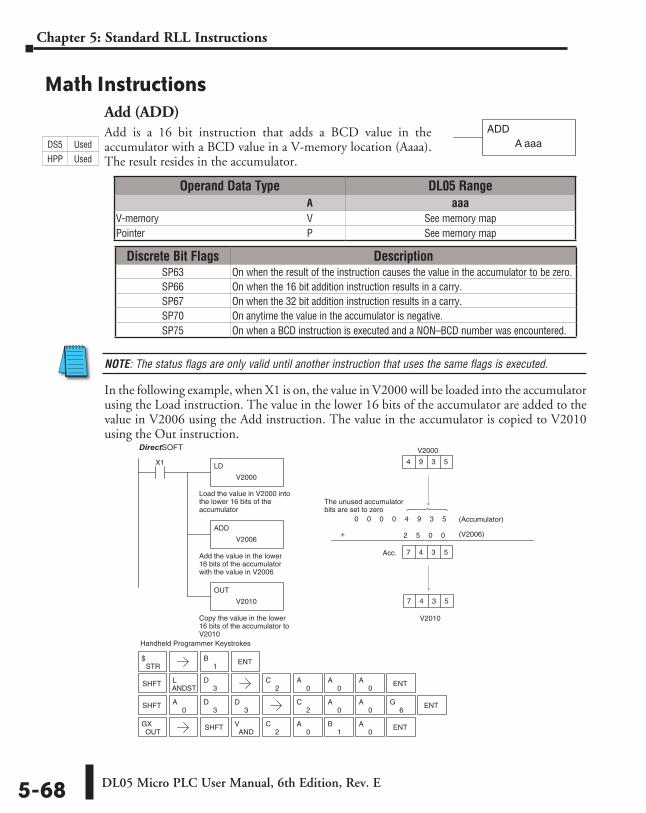
DL05 Micro PLC User Manual, 6th Edition, Rev. E5-68
Chapter 5: Standard RLL Instructions
Math InstructionsAdd (ADD)Add is a 16 bit instruction that adds a BCD value in the accumulator with a BCD value in a V-memory location (Aaaa). The result resides in the accumulator.
NOTE: The status flags are only valid until another instruction that uses the same flags is executed.
In the following example, when X1 is on, the value in V2000 will be loaded into the accumulator using the Load instruction. The value in the lower 16 bits of the accumulator are added to the value in V2006 using the Add instruction. The value in the accumulator is copied to V2010 using the Out instruction.
ADDA aaa
Discrete Bit Flags DescriptionSP63 On when the result of the instruction causes the value in the accumulator to be zero.SP66 On when the 16 bit addition instruction results in a carry.SP67 On when the 32 bit addition instruction results in a carry.SP70 On anytime the value in the accumulator is negative.SP75 On when a BCD instruction is executed and a NON–BCD number was encountered.
Direct SOFT32
Handheld Programmer Keystrokes
LD
V2000
X1
Load the value in V2000 intothe lower 16 bits of theaccumulator
ADD
V2006
Add the value in the lower16 bits of the accumulatorwith the value in V2006
OUT
V2010
Copy the value in the lower16 bits of the accumulator toV2010
V2010
V2000
4 9 3 5
7 4 3 5
0 0 0 0 4 9 3 5
+ 2 5 0 0
Acc. 7 4 3 5
(V2006)
(Accumulator)
The unused accumulatorbits are set to zero
SHFTANDSTL
3D
STR$
SHFT0
A3
D3
D
OUTGX SHFT
ANDV
2C
0A
1B
0A ENT
1B ENT
2C
0A
0A
0A ENT
2C
0A
0A ENT
6G
Operand Data Type DL05 Range ⸠⸠⸠⸠⸠⸠⸠⸠⸠⸠⸠⸠⸠⸠⸠⸠⸠⸠⸠⸠⸠⸠⸠⸠⸠⸠⸠⸠⸠⸠⸠⸠⸠⸠⸠⸠⸠⸠⸠⸠⸠⸠⸠⸠⸠⸠⸠⸠⸠⸠⸠⸠⸠⸠⸠⸠⸠⸠⸠⸠⸠⸠⸠⸠⸠⸠⸠⸠⸠⸠⸠⸠⸠A aaaV-memory ⸠⸠⸠⸠⸠⸠⸠⸠⸠⸠⸠⸠⸠⸠⸠⸠⸠⸠⸠⸠⸠⸠⸠⸠⸠⸠⸠⸠⸠⸠⸠⸠⸠⸠⸠⸠⸠⸠⸠⸠⸠⸠⸠⸠⸠⸠⸠⸠⸠⸠⸠⸠⸠⸠⸠⸠⸠⸠V See memory mapPointer ⸠⸠⸠⸠⸠⸠⸠⸠⸠⸠⸠⸠⸠⸠⸠⸠⸠⸠⸠⸠⸠⸠⸠⸠⸠⸠⸠⸠⸠⸠⸠⸠⸠⸠⸠⸠⸠⸠⸠⸠⸠⸠⸠⸠⸠⸠⸠⸠⸠⸠⸠⸠⸠⸠⸠⸠⸠⸠⸠⸠⸠⸠⸠⸠P See memory map
DS5 Used
HPP Used
DirectSOFT
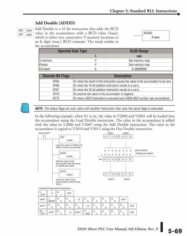
DL05 Micro PLC User Manual, 6th Edition, Rev. E 5-69
Chapter 5: Standard RLL Instructions
Add Double (ADDD)Add Double is a 32 bit instruction that adds the BCD value in the accumulator with a BCD value (Aaaa), which is either two consecutive V-memory locations or an 8–digit (max.) BCD constant. The result resides in the accumulator.
NOTE: The status flags are only valid until another instruction that uses the same flags is executed.
In the following example, when X1 is on, the value in V2000 and V2001 will be loaded into the accumulator using the Load Double instruction. The value in the accumulator is added with the value in V2006 and V2007 using the Add Double instruction. The value in the accumulator is copied to V2010 and V2011 using the Out Double instruction.
ADDDA aaa
6 7 3 9 5 0 2 6
Direct SOFT
Handheld Programmer Keystrokes
LDD
V2000
X1
Load the value in V2000 andV2001 into the accumulator
ADDD
V2006
Add the value in theaccumulator with the valuein V2006 and V2007
OUTD
V2010
Copy the value in theaccumulator to V2010 andV2011
V2010
V2000
V2001
6 7 3 9 5 0 2 6
V2011
8 7 3 9 9 0 7 2
(Accumulator)
2 0 0 0 4 0 4 6 +
8 7 3 9 9 0 7 2 Acc.
STR$
1B
SHFT0
A3
D3
D
SHFTANDSTL
3D
3D
3D
OUTGX SHFT
3D
ANDV
2C
0A
1B
0A ENTSHFT
ENT
2C
0A
0A ENT
6G
2C
0A
0A
0A ENT
(V2006 and V2007)
Discrete Bit Flags DescriptionSP63 On when the result of the instruction causes the value in the accumulator to be zero.SP66 On when the 16 bit addition instruction results in a carry.SP67 On when the 32 bit addition instruction results in a carry.SP70 On anytime the value in the accumulator is negative.SP75 On when a BCD instruction is executed and a NON–BCD number was encountered.
Operand Data Type DL05 Range ⸠⸠⸠⸠⸠⸠⸠⸠⸠⸠⸠⸠⸠⸠⸠⸠⸠⸠⸠⸠⸠⸠⸠⸠⸠⸠⸠⸠⸠⸠⸠⸠⸠⸠⸠⸠⸠⸠⸠⸠⸠⸠⸠⸠⸠⸠⸠⸠⸠⸠⸠⸠⸠⸠⸠⸠⸠⸠⸠⸠⸠⸠⸠⸠⸠⸠⸠⸠⸠⸠⸠⸠⸠A aaaV-memory ⸠⸠⸠⸠⸠⸠⸠⸠⸠⸠⸠⸠⸠⸠⸠⸠⸠⸠⸠⸠⸠⸠⸠⸠⸠⸠⸠⸠⸠⸠⸠⸠⸠⸠⸠⸠⸠⸠⸠⸠⸠⸠⸠⸠⸠⸠⸠⸠⸠⸠⸠⸠⸠⸠⸠⸠⸠⸠V See memory mapPointer ⸠⸠⸠⸠⸠⸠⸠⸠⸠⸠⸠⸠⸠⸠⸠⸠⸠⸠⸠⸠⸠⸠⸠⸠⸠⸠⸠⸠⸠⸠⸠⸠⸠⸠⸠⸠⸠⸠⸠⸠⸠⸠⸠⸠⸠⸠⸠⸠⸠⸠⸠⸠⸠⸠⸠⸠⸠⸠⸠⸠⸠⸠⸠⸠P See memory mapConstant ⸠⸠⸠⸠⸠⸠⸠⸠⸠⸠⸠⸠⸠⸠⸠⸠⸠⸠⸠⸠⸠⸠⸠⸠⸠⸠⸠⸠⸠⸠⸠⸠⸠⸠⸠⸠⸠⸠⸠⸠⸠⸠⸠⸠⸠⸠⸠⸠⸠⸠⸠⸠⸠⸠⸠⸠⸠⸠⸠⸠⸠K 0–99999999
DS5 Used
HPP Used
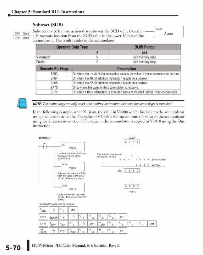
DL05 Micro PLC User Manual, 6th Edition, Rev. E5-70
Chapter 5: Standard RLL Instructions
Subtract (SUB)Subtract is a 16 bit instruction that subtracts the BCD value (Aaaa) in a V-memory location from the BCD value in the lower 16 bits of the accumulator. The result resides in the accumulator.
NOTE: The status flags are only valid until another instruction that uses the same flags is executed.
In the following example, when X1 is on, the value in V2000 will be loaded into the accumulator using the Load instruction. The value in V2006 is subtracted from the value in the accumulator using the Subtract instruction. The value in the accumulator is copied to V2010 using the Out instruction.
SUBA aaa
Direct SOFT32
Handheld Programmer Keystrokes
LD
V2000
X1
Load the value in V2000 intothe lower 16 bits of theaccumulator
SUB
V2006
Subtract the value in V2006from the value in the lower16 bits of the accumulator
OUT
V2010
Copy the value in the lower16 bits of the accumulator toV2010
V2010
2
0
0
_
V2000
4 7 5
8 8 3
0 0 0 0 2 4 7 5
1 5 9 2
Acc. 8 8 3
The unused accumulatorbits are set to zero
SHFTANDSTL
3D
STR$
SHFT SHFTAND
V2
C0
A0
A ENT6
G
OUTGX SHFT
ANDV
2C
0A
1B
0A ENT
RSTS
ISGU
1B
1B ENT
2C
0A
0A
0A ENT
(V2006)
(Accumulator)
Operand Data Type DL05 Range ⸠⸠⸠⸠⸠⸠⸠⸠⸠⸠⸠⸠⸠⸠⸠⸠⸠⸠⸠⸠⸠⸠⸠⸠⸠⸠⸠⸠⸠⸠⸠⸠⸠⸠⸠⸠⸠⸠⸠⸠⸠⸠⸠⸠⸠⸠⸠⸠⸠⸠⸠⸠⸠⸠⸠⸠⸠⸠⸠⸠⸠⸠⸠⸠⸠⸠⸠⸠⸠⸠⸠⸠⸠A aaaV-memory ⸠⸠⸠⸠⸠⸠⸠⸠⸠⸠⸠⸠⸠⸠⸠⸠⸠⸠⸠⸠⸠⸠⸠⸠⸠⸠⸠⸠⸠⸠⸠⸠⸠⸠⸠⸠⸠⸠⸠⸠⸠⸠⸠⸠⸠⸠⸠⸠⸠⸠⸠⸠⸠⸠⸠⸠⸠⸠V See memory mapPointer ⸠⸠⸠⸠⸠⸠⸠⸠⸠⸠⸠⸠⸠⸠⸠⸠⸠⸠⸠⸠⸠⸠⸠⸠⸠⸠⸠⸠⸠⸠⸠⸠⸠⸠⸠⸠⸠⸠⸠⸠⸠⸠⸠⸠⸠⸠⸠⸠⸠⸠⸠⸠⸠⸠⸠⸠⸠⸠⸠⸠⸠⸠⸠⸠P See memory map
Discrete Bit Flags DescriptionSP63 On when the result of the instruction causes the value in the accumulator to be zero.SP64 On when the 16 bit addition instruction results in a borrowSP65 On when the 32 bit addition instruction results in a borrowSP70 On anytime the value in the accumulator is negative.SP75 On when a BCD instruction is executed and a NON–BCD number was encountered.
DS5 Used
HPP Used
DirectSOFT
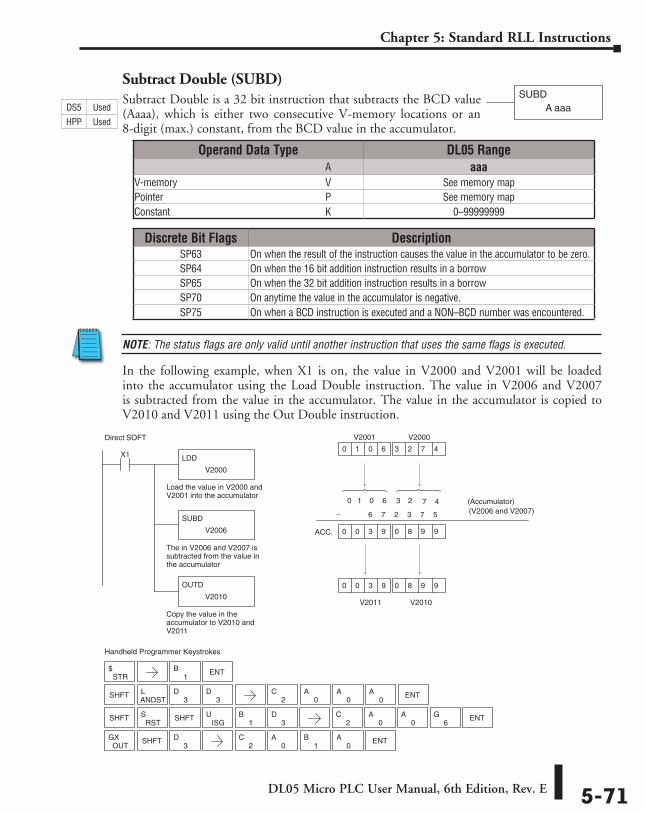
DL05 Micro PLC User Manual, 6th Edition, Rev. E 5-71
Chapter 5: Standard RLL Instructions
Subtract Double (SUBD)Subtract Double is a 32 bit instruction that subtracts the BCD value (Aaaa), which is either two consecutive V-memory locations or an 8-digit (max.) constant, from the BCD value in the accumulator.
NOTE: The status flags are only valid until another instruction that uses the same flags is executed.
In the following example, when X1 is on, the value in V2000 and V2001 will be loaded into the accumulator using the Load Double instruction. The value in V2006 and V2007 is subtracted from the value in the accumulator. The value in the accumulator is copied to V2010 and V2011 using the Out Double instruction.
SUBDA aaa
Discrete Bit Flags DescriptionSP63 On when the result of the instruction causes the value in the accumulator to be zero.SP64 On when the 16 bit addition instruction results in a borrowSP65 On when the 32 bit addition instruction results in a borrowSP70 On anytime the value in the accumulator is negative.SP75 On when a BCD instruction is executed and a NON–BCD number was encountered.
Operand Data Type DL05 Range ⸠⸠⸠⸠⸠⸠⸠⸠⸠⸠⸠⸠⸠⸠⸠⸠⸠⸠⸠⸠⸠⸠⸠⸠⸠⸠⸠⸠⸠⸠⸠⸠⸠⸠⸠⸠⸠⸠⸠⸠⸠⸠⸠⸠⸠⸠⸠⸠⸠⸠⸠⸠⸠⸠⸠⸠⸠⸠⸠⸠⸠⸠⸠⸠⸠⸠⸠⸠⸠⸠⸠⸠⸠A aaaV-memory ⸠⸠⸠⸠⸠⸠⸠⸠⸠⸠⸠⸠⸠⸠⸠⸠⸠⸠⸠⸠⸠⸠⸠⸠⸠⸠⸠⸠⸠⸠⸠⸠⸠⸠⸠⸠⸠⸠⸠⸠⸠⸠⸠⸠⸠⸠⸠⸠⸠⸠⸠⸠⸠⸠⸠⸠⸠⸠V See memory mapPointer ⸠⸠⸠⸠⸠⸠⸠⸠⸠⸠⸠⸠⸠⸠⸠⸠⸠⸠⸠⸠⸠⸠⸠⸠⸠⸠⸠⸠⸠⸠⸠⸠⸠⸠⸠⸠⸠⸠⸠⸠⸠⸠⸠⸠⸠⸠⸠⸠⸠⸠⸠⸠⸠⸠⸠⸠⸠⸠⸠⸠⸠⸠⸠⸠P See memory mapConstant ⸠⸠⸠⸠⸠⸠⸠⸠⸠⸠⸠⸠⸠⸠⸠⸠⸠⸠⸠⸠⸠⸠⸠⸠⸠⸠⸠⸠⸠⸠⸠⸠⸠⸠⸠⸠⸠⸠⸠⸠⸠⸠⸠⸠⸠⸠⸠⸠⸠⸠⸠⸠⸠⸠⸠⸠⸠⸠⸠⸠⸠K 0–99999999
Direct SOFT
Handheld Programmer Keystrokes
LDD
V2000
X1
Load the value in V2000 andV2001 into the accumulator
SUBD
V2006
The in V2006 and V2007 issubtracted from the value inthe accumulator
OUTD
V2010
Copy the value in theaccumulator to V2010 andV2011
0 0 3 9 0 8 9 9
0 1 0 6 3 2 7 4
0 1 0 6 3 2 7 4 (Accumulator)
V2010
V2000
V2001
V2011
0 0 3 9 0 8 9 9
6 7 2 3 7 5
ACC.
STR$
SHFT
SHFTANDSTL
3D
3D
3D
OUTGX SHFT
3D
RSTS
ISGU
1B
1B ENT
2C
0A
0A ENT
6G
2C
0A
0A
0A ENT
2C
0A
1B
0A ENT
SHFT
_ (V2006 and V2007)
DS5 Used
HPP Used
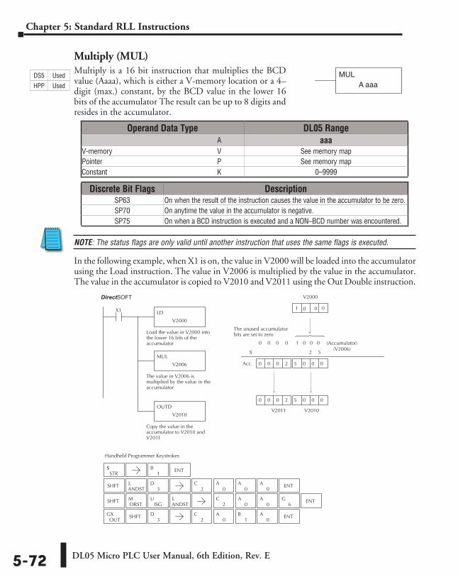
DL05 Micro PLC User Manual, 6th Edition, Rev. E5-72
Chapter 5: Standard RLL Instructions
Multiply (MUL)Multiply is a 16 bit instruction that multiplies the BCD value (Aaaa), which is either a V-memory location or a 4–digit (max.) constant, by the BCD value in the lower 16 bits of the accumulator The result can be up to 8 digits and resides in the accumulator.
NOTE: The status flags are only valid until another instruction that uses the same flags is executed.
In the following example, when X1 is on, the value in V2000 will be loaded into the accumulator using the Load instruction. The value in V2006 is multiplied by the value in the accumulator. The value in the accumulator is copied to V2010 and V2011 using the Out Double instruction.
MULA aaa
Direct SOFT32
Handheld Programmer Keystrokes
LD
V2000
X1
Load the value in V2000 intothe lower 16 bits of theaccumulator
MUL
V2006
The value in V2006 ismultiplied by the value in theaccumulator
OUTD
V2010
Copy the value in theaccumulator to V2010 andV2011
0 0 0 2 5 0 0 0
0
X
0 0 0 0 1 0 0 0
V2010
1
V2000 0
0 0 0 2 5 0 0 0
2 5
The unused accumulatorbits are set to zero
Acc.
STR$
SHFTANDSTL
3D
SHFTORSTM
ISGU
ANDSTL
OUTGX SHFT
3D
1B ENT
2C
0A
0A
0A ENT
2C
0A
0A ENT
6G
2C
0A
1B
0A ENT
0
V2011
(Accumulator) (V2006)
Operand Data Type DL05 Range ⸠⸠⸠⸠⸠⸠⸠⸠⸠⸠⸠⸠⸠⸠⸠⸠⸠⸠⸠⸠⸠⸠⸠⸠⸠⸠⸠⸠⸠⸠⸠⸠⸠⸠⸠⸠⸠⸠⸠⸠⸠⸠⸠⸠⸠⸠⸠⸠⸠⸠⸠⸠⸠⸠⸠⸠⸠⸠⸠⸠⸠⸠⸠⸠⸠⸠⸠⸠⸠⸠⸠⸠⸠A aaaV-memory ⸠⸠⸠⸠⸠⸠⸠⸠⸠⸠⸠⸠⸠⸠⸠⸠⸠⸠⸠⸠⸠⸠⸠⸠⸠⸠⸠⸠⸠⸠⸠⸠⸠⸠⸠⸠⸠⸠⸠⸠⸠⸠⸠⸠⸠⸠⸠⸠⸠⸠⸠⸠⸠⸠⸠⸠⸠⸠V See memory mapPointer ⸠⸠⸠⸠⸠⸠⸠⸠⸠⸠⸠⸠⸠⸠⸠⸠⸠⸠⸠⸠⸠⸠⸠⸠⸠⸠⸠⸠⸠⸠⸠⸠⸠⸠⸠⸠⸠⸠⸠⸠⸠⸠⸠⸠⸠⸠⸠⸠⸠⸠⸠⸠⸠⸠⸠⸠⸠⸠⸠⸠⸠⸠⸠⸠P See memory mapConstant ⸠⸠⸠⸠⸠⸠⸠⸠⸠⸠⸠⸠⸠⸠⸠⸠⸠⸠⸠⸠⸠⸠⸠⸠⸠⸠⸠⸠⸠⸠⸠⸠⸠⸠⸠⸠⸠⸠⸠⸠⸠⸠⸠⸠⸠⸠⸠⸠⸠⸠⸠⸠⸠⸠⸠⸠⸠⸠⸠⸠⸠K 0–9999
Discrete Bit Flags DescriptionSP63 On when the result of the instruction causes the value in the accumulator to be zero.SP70 On anytime the value in the accumulator is negative.SP75 On when a BCD instruction is executed and a NON–BCD number was encountered.
DS5 Used
HPP Used
DirectSOFT
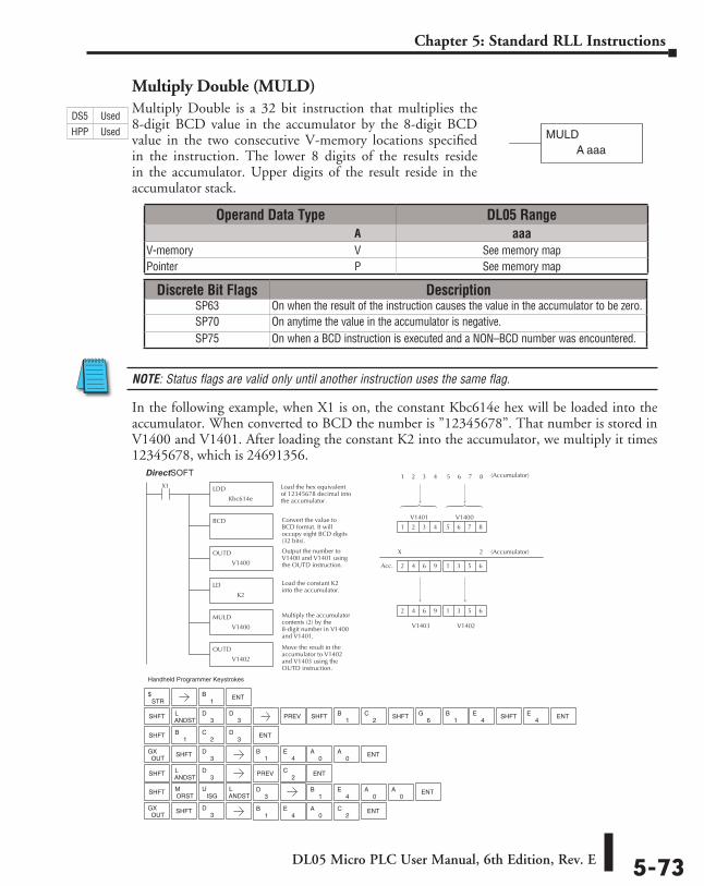
DL05 Micro PLC User Manual, 6th Edition, Rev. E 5-73
Chapter 5: Standard RLL Instructions
Multiply Double (MULD)Multiply Double is a 32 bit instruction that multiplies the 8-digit BCD value in the accumulator by the 8-digit BCD value in the two consecutive V-memory locations specified in the instruction. The lower 8 digits of the results reside in the accumulator. Upper digits of the result reside in the accumulator stack.
NOTE: Status flags are valid only until another instruction uses the same flag.
In the following example, when X1 is on, the constant Kbc614e hex will be loaded into the accumulator. When converted to BCD the number is ”12345678”. That number is stored in V1400 and V1401. After loading the constant K2 into the accumulator, we multiply it times 12345678, which is 24691356.
MULDA aaa
Direct SOFT32 Display
LDD
Kbc614e
X1 Load the hex equivalentof 12345678 decimal intothe accumulator.
BCD Convert the value toBCD format. It willoccupy eight BCD digits(32 bits).
OUTD
V1400
Output the number toV1400 and V1401 usingthe OUTD instruction. 3 5 62 4 6 9
6 7 8
(Accumulator)
1 2 3 4 5 6 7 8
1
(Accumulator)
V1402
1
5
V1400
3 5 6
V1403
2 4 6 9
2
Acc.
LD
K2
Load the constant K2into the accumulator.
MULD
V1400
Multiply the accumulatorcontents (2) by the8-digit number in V1400and V1401.
OUTD
V1402
Move the result in theaccumulator to V1402and V1403 using theOUTD instruction.
2 3 41
V1401
X
Handheld Programmer Keystrokes
STR$
SHFTANDSTL
3D
SHFTORSTM
ISGU
ANDSTL
OUTGX SHFT
3D
1B ENT
6G
1B
4E ENT
ENT
ENT
3D PREV SHFT
1B
2C SHFT SHFT
4E
SHFT1
B2
C3
D
OUTGX SHFT
3D
1B
4E
0A ENT
0A
ENT
SHFTANDSTL
3D PREV ENT
2C
3D
1B
4E
0A
0A
1B
4E
0A
2C
Operand Data Type DL05 Range ⸠⸠⸠⸠⸠⸠⸠⸠⸠⸠⸠⸠⸠⸠⸠⸠⸠⸠⸠⸠⸠⸠⸠⸠⸠⸠⸠⸠⸠⸠⸠⸠⸠⸠⸠⸠⸠⸠⸠⸠⸠⸠⸠⸠⸠⸠⸠⸠⸠⸠⸠⸠⸠⸠⸠⸠⸠⸠⸠⸠⸠⸠⸠⸠⸠⸠⸠⸠⸠⸠⸠⸠⸠A aaaV-memory ⸠⸠⸠⸠⸠⸠⸠⸠⸠⸠⸠⸠⸠⸠⸠⸠⸠⸠⸠⸠⸠⸠⸠⸠⸠⸠⸠⸠⸠⸠⸠⸠⸠⸠⸠⸠⸠⸠⸠⸠⸠⸠⸠⸠⸠⸠⸠⸠⸠⸠⸠⸠⸠⸠⸠⸠⸠⸠V See memory mapPointer ⸠⸠⸠⸠⸠⸠⸠⸠⸠⸠⸠⸠⸠⸠⸠⸠⸠⸠⸠⸠⸠⸠⸠⸠⸠⸠⸠⸠⸠⸠⸠⸠⸠⸠⸠⸠⸠⸠⸠⸠⸠⸠⸠⸠⸠⸠⸠⸠⸠⸠⸠⸠⸠⸠⸠⸠⸠⸠⸠⸠⸠⸠⸠⸠P See memory map
Discrete Bit Flags DescriptionSP63 On when the result of the instruction causes the value in the accumulator to be zero.SP70 On anytime the value in the accumulator is negative.SP75 On when a BCD instruction is executed and a NON–BCD number was encountered.
DS5 Used
HPP Used
DirectSOFT
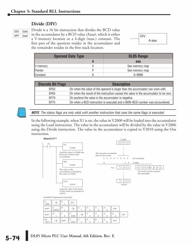
DL05 Micro PLC User Manual, 6th Edition, Rev. E5-74
Chapter 5: Standard RLL Instructions
Divide (DIV)Divide is a 16 bit instruction that divides the BCD value in the accumulator by a BCD value (Aaaa), which is either a V-memory location or a 4-digit (max.) constant. The first part of the quotient resides in the accumulator and the remainder resides in the first stack location.
NOTE: The status flags are only valid until another instruction that uses the same flags is executed.
In the following example, when X1 is on, the value in V2000 will be loaded into the accumulator using the Load instruction. The value in the accumulator will be divided by the value in V2006 using the Divide instruction. The value in the accumulator is copied to V2010 using the Out instruction.
DIVA aaa
Discrete Bit Flags DescriptionSP53 On when the value of the operand is larger than the accumulator can work with.SP63 On when the result of the instruction causes the value in the accumulator to be zero.SP70 On anytime the value in the accumulator is negative.SP75 On when a BCD instruction is executed and a NON–BCD number was encountered.
Direct SOFT32
Handheld Programmer Keystrokes
LD
V2000
X1
Load the value in V2000 intothe lower 16 bits of theaccumulator
DIV
V2006
The value in theaccumulator is divided bythe value in V2006
OUT
V2010
Copy the value in the lower16 bits of the accumulator toV2010
V2010
0
5
V2000
0 0 0
0 0 0 5 0 0 0
4 9
Acc. 1 0 2
The unused accumulatorbits are set to zero
0 0 0 0 0 0 0 2
First stak location contains the remainder
STR$
SHFTANDSTL
3D
SHFT3
D8
IAND
V
OUTGX SHFT
ANDV
2C
0A
1B
0A ENT
1B ENT
2C
0A
0A
0A ENT
2C
0A
0A ENT
6G
(Accumulater)
V2006÷
1 20
Operand Data Type DL05 Range ⸠⸠⸠⸠⸠⸠⸠⸠⸠⸠⸠⸠⸠⸠⸠⸠⸠⸠⸠⸠⸠⸠⸠⸠⸠⸠⸠⸠⸠⸠⸠⸠⸠⸠⸠⸠⸠⸠⸠⸠⸠⸠⸠⸠⸠⸠⸠⸠⸠⸠⸠⸠⸠⸠⸠⸠⸠⸠⸠⸠⸠⸠⸠⸠⸠⸠⸠⸠⸠⸠⸠⸠⸠A aaaV-memory ⸠⸠⸠⸠⸠⸠⸠⸠⸠⸠⸠⸠⸠⸠⸠⸠⸠⸠⸠⸠⸠⸠⸠⸠⸠⸠⸠⸠⸠⸠⸠⸠⸠⸠⸠⸠⸠⸠⸠⸠⸠⸠⸠⸠⸠⸠⸠⸠⸠⸠⸠⸠⸠⸠⸠⸠⸠⸠V See memory mapPointer ⸠⸠⸠⸠⸠⸠⸠⸠⸠⸠⸠⸠⸠⸠⸠⸠⸠⸠⸠⸠⸠⸠⸠⸠⸠⸠⸠⸠⸠⸠⸠⸠⸠⸠⸠⸠⸠⸠⸠⸠⸠⸠⸠⸠⸠⸠⸠⸠⸠⸠⸠⸠⸠⸠⸠⸠⸠⸠⸠⸠⸠⸠⸠⸠P See memory mapConstant ⸠⸠⸠⸠⸠⸠⸠⸠⸠⸠⸠⸠⸠⸠⸠⸠⸠⸠⸠⸠⸠⸠⸠⸠⸠⸠⸠⸠⸠⸠⸠⸠⸠⸠⸠⸠⸠⸠⸠⸠⸠⸠⸠⸠⸠⸠⸠⸠⸠⸠⸠⸠⸠⸠⸠⸠⸠⸠⸠⸠⸠K 0–9999
DS5 Used
HPP Used
DirectSOFT
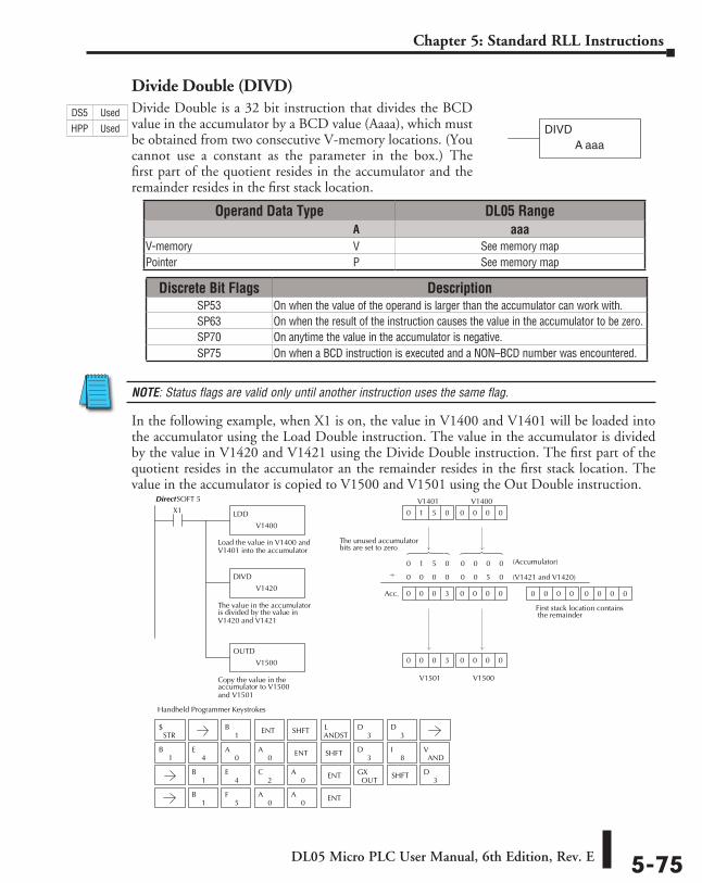
DL05 Micro PLC User Manual, 6th Edition, Rev. E 5-75
Chapter 5: Standard RLL Instructions
Divide Double (DIVD)Divide Double is a 32 bit instruction that divides the BCD value in the accumulator by a BCD value (Aaaa), which must be obtained from two consecutive V-memory locations. (You cannot use a constant as the parameter in the box.) The first part of the quotient resides in the accumulator and the remainder resides in the first stack location.
NOTE: Status flags are valid only until another instruction uses the same flag.
In the following example, when X1 is on, the value in V1400 and V1401 will be loaded into the accumulator using the Load Double instruction. The value in the accumulator is divided by the value in V1420 and V1421 using the Divide Double instruction. The first part of the quotient resides in the accumulator an the remainder resides in the first stack location. The value in the accumulator is copied to V1500 and V1501 using the Out Double instruction.
DIVDA aaa
DirectSOFT 5
Handheld Programmer Keystrokes
LDD
V1400
X1
Load the value in V1400 andV1401 into the accumulator
DIVD
V1420
The value in the accumulatoris divided by the value inV1420 and V1421
OUTD
V1500
Copy the value in theaccumulator to V1500and V1501
0 0 00 0 0 3
0 0 00 1 5 0
0 (Accumulator)
(V1421 and V1420)
0
0
1 5 0 0 0 0 0
0
V1500
V1400
0
0 0 0
V1401
V1501
0 0 0 3
0 0 0 0 0 5 0
0 0 00 0 0 0 0
First stack location contains the remainder
The unused accumulatorbits are set to zero
Acc.
SHFT
SHFT
SHFT
1B ENT
ANDSTL
3D
STR$
3D
ENT
ENT3
D
3D
1B
4E
0A
0A
8I
ANDV
1B
5F
0A
0A
OUTGX
1B
4E
0A
2C ENT
�
Operand Data Type DL05 Range ⸠⸠⸠⸠⸠⸠⸠⸠⸠⸠⸠⸠⸠⸠⸠⸠⸠⸠⸠⸠⸠⸠⸠⸠⸠⸠⸠⸠⸠⸠⸠⸠⸠⸠⸠⸠⸠⸠⸠⸠⸠⸠⸠⸠⸠⸠⸠⸠⸠⸠⸠⸠⸠⸠⸠⸠⸠⸠⸠⸠⸠⸠⸠⸠⸠⸠⸠⸠⸠⸠⸠⸠⸠A aaaV-memory ⸠⸠⸠⸠⸠⸠⸠⸠⸠⸠⸠⸠⸠⸠⸠⸠⸠⸠⸠⸠⸠⸠⸠⸠⸠⸠⸠⸠⸠⸠⸠⸠⸠⸠⸠⸠⸠⸠⸠⸠⸠⸠⸠⸠⸠⸠⸠⸠⸠⸠⸠⸠⸠⸠⸠⸠⸠⸠V See memory mapPointer ⸠⸠⸠⸠⸠⸠⸠⸠⸠⸠⸠⸠⸠⸠⸠⸠⸠⸠⸠⸠⸠⸠⸠⸠⸠⸠⸠⸠⸠⸠⸠⸠⸠⸠⸠⸠⸠⸠⸠⸠⸠⸠⸠⸠⸠⸠⸠⸠⸠⸠⸠⸠⸠⸠⸠⸠⸠⸠⸠⸠⸠⸠⸠⸠P See memory map
Discrete Bit Flags DescriptionSP53 On when the value of the operand is larger than the accumulator can work with.SP63 On when the result of the instruction causes the value in the accumulator to be zero.SP70 On anytime the value in the accumulator is negative.SP75 On when a BCD instruction is executed and a NON–BCD number was encountered.
DS5 Used
HPP Used
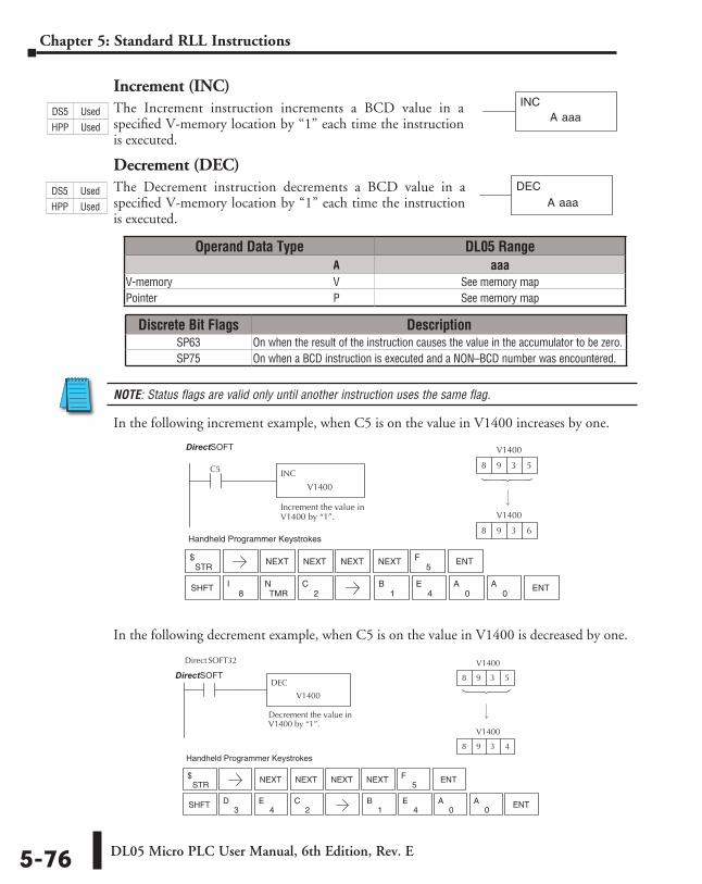
DL05 Micro PLC User Manual, 6th Edition, Rev. E5-76
Chapter 5: Standard RLL Instructions
Increment (INC)The Increment instruction increments a BCD value in a specified V-memory location by “1” each time the instruction is executed.
Decrement (DEC)The Decrement instruction decrements a BCD value in a specified V-memory location by “1” each time the instruction is executed.
NOTE: Status flags are valid only until another instruction uses the same flag.
In the following increment example, when C5 is on the value in V1400 increases by one.
In the following decrement example, when C5 is on the value in V1400 is decreased by one.
A aaaINC
A aaaDEC
Direct SOFT32
C5 INC
V1400
Increment the value inV1400 by “1”.
V1400
8 9 3 5
V1400
8 9 3 6Handheld Programmer Keystrokes
STR$
5F ENT
8I ENT
NEXT NEXT NEXT NEXT
SHFTTMR
N1
B4
E0
A0
A2
C
Operand Data Type DL05 Range ⸠⸠⸠⸠⸠⸠⸠⸠⸠⸠⸠⸠⸠⸠⸠⸠⸠⸠⸠⸠⸠⸠⸠⸠⸠⸠⸠⸠⸠⸠⸠⸠⸠⸠⸠⸠⸠⸠⸠⸠⸠⸠⸠⸠⸠⸠⸠⸠⸠⸠⸠⸠⸠⸠⸠⸠⸠⸠⸠⸠⸠⸠⸠⸠⸠⸠⸠⸠⸠⸠⸠⸠⸠A aaaV-memory ⸠⸠⸠⸠⸠⸠⸠⸠⸠⸠⸠⸠⸠⸠⸠⸠⸠⸠⸠⸠⸠⸠⸠⸠⸠⸠⸠⸠⸠⸠⸠⸠⸠⸠⸠⸠⸠⸠⸠⸠⸠⸠⸠⸠⸠⸠⸠⸠⸠⸠⸠⸠⸠⸠⸠⸠⸠⸠V See memory mapPointer ⸠⸠⸠⸠⸠⸠⸠⸠⸠⸠⸠⸠⸠⸠⸠⸠⸠⸠⸠⸠⸠⸠⸠⸠⸠⸠⸠⸠⸠⸠⸠⸠⸠⸠⸠⸠⸠⸠⸠⸠⸠⸠⸠⸠⸠⸠⸠⸠⸠⸠⸠⸠⸠⸠⸠⸠⸠⸠⸠⸠⸠⸠⸠⸠P See memory map
Discrete Bit Flags DescriptionSP63 On when the result of the instruction causes the value in the accumulator to be zero.SP75 On when a BCD instruction is executed and a NON–BCD number was encountered.
Direct SOFT32
C5 DEC
V1400
Decrement the value inV1400 by “1”.
V1400
8 9 3 5
V1400
8 9 3 4Handheld Programmer Keystrokes
STR$
5F ENT
3D ENT
NEXT NEXT NEXT NEXT
SHFT4
E1
B4
E0
A0
A2
C
DS5 Used
HPP Used
DS5 Used
HPP Used
DirectSOFT
DirectSOFT
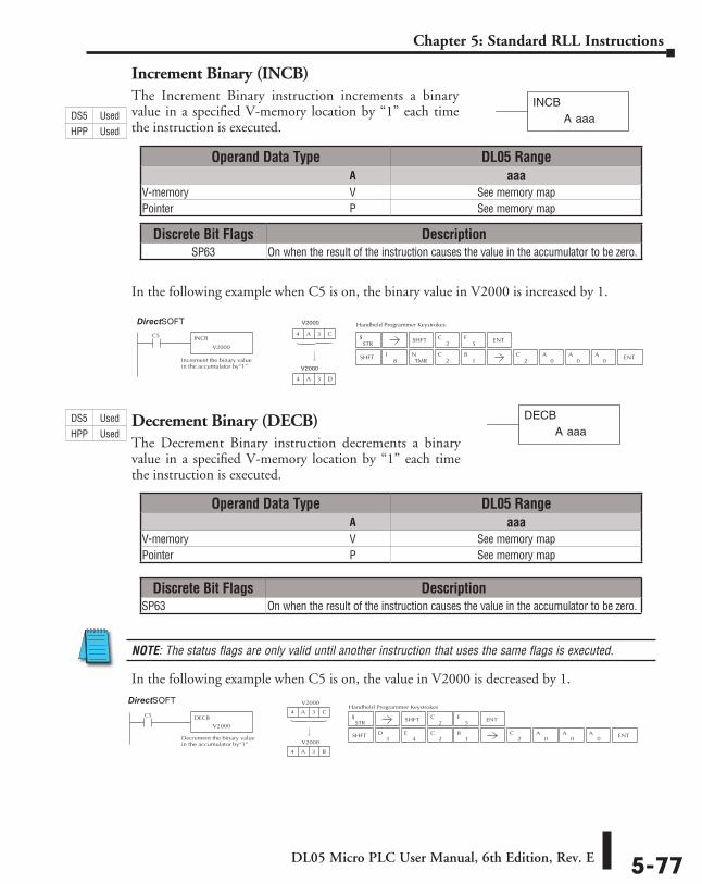
DL05 Micro PLC User Manual, 6th Edition, Rev. E 5-77
Chapter 5: Standard RLL Instructions
Increment Binary (INCB)The Increment Binary instruction increments a binary value in a specified V-memory location by “1” each time the instruction is executed.
In the following example when C5 is on, the binary value in V2000 is increased by 1.
Decrement Binary (DECB)The Decrement Binary instruction decrements a binary value in a specified V-memory location by “1” each time the instruction is executed.
NOTE: The status flags are only valid until another instruction that uses the same flags is executed.
In the following example when C5 is on, the value in V2000 is decreased by 1.
A aaaINCB
Handheld Programmer KeystrokesDirect SOFT32
C5 INCB
V2000
Increment the binary valuein the accumulator by“1”
4 A 3 C
4 A 3 D
STR$
2C
5FSHFT ENT
SHFT8
ITMR
N2
C1
B2
C0
A0
A0
A ENT
V2000
V2000
Handheld Programmer KeystrokesDirect SOFT32
C5 DECB
V2000
Decrement the binary valuein the accumulator by“1”
V2000
4 A 3 C
V2000
4 A 3 B
STR$
2C
5FSHFT ENT
SHFT2
C3
D4
E1
B2
C0
A0
A0
A ENT
Operand Data Type DL05 Range ⸠⸠⸠⸠⸠⸠⸠⸠⸠⸠⸠⸠⸠⸠⸠⸠⸠⸠⸠⸠⸠⸠⸠⸠⸠⸠⸠⸠⸠⸠⸠⸠⸠⸠⸠⸠⸠⸠⸠⸠⸠⸠⸠⸠⸠⸠⸠⸠⸠⸠⸠⸠⸠⸠⸠⸠⸠⸠⸠⸠⸠⸠⸠⸠⸠⸠⸠⸠⸠⸠⸠⸠⸠A aaaV-memory ⸠⸠⸠⸠⸠⸠⸠⸠⸠⸠⸠⸠⸠⸠⸠⸠⸠⸠⸠⸠⸠⸠⸠⸠⸠⸠⸠⸠⸠⸠⸠⸠⸠⸠⸠⸠⸠⸠⸠⸠⸠⸠⸠⸠⸠⸠⸠⸠⸠⸠⸠⸠⸠⸠⸠⸠⸠⸠V See memory mapPointer ⸠⸠⸠⸠⸠⸠⸠⸠⸠⸠⸠⸠⸠⸠⸠⸠⸠⸠⸠⸠⸠⸠⸠⸠⸠⸠⸠⸠⸠⸠⸠⸠⸠⸠⸠⸠⸠⸠⸠⸠⸠⸠⸠⸠⸠⸠⸠⸠⸠⸠⸠⸠⸠⸠⸠⸠⸠⸠⸠⸠⸠⸠⸠⸠P See memory map
Operand Data Type DL05 Range ⸠⸠⸠⸠⸠⸠⸠⸠⸠⸠⸠⸠⸠⸠⸠⸠⸠⸠⸠⸠⸠⸠⸠⸠⸠⸠⸠⸠⸠⸠⸠⸠⸠⸠⸠⸠⸠⸠⸠⸠⸠⸠⸠⸠⸠⸠⸠⸠⸠⸠⸠⸠⸠⸠⸠⸠⸠⸠⸠⸠⸠⸠⸠⸠⸠⸠⸠⸠⸠⸠⸠⸠⸠A aaaV-memory ⸠⸠⸠⸠⸠⸠⸠⸠⸠⸠⸠⸠⸠⸠⸠⸠⸠⸠⸠⸠⸠⸠⸠⸠⸠⸠⸠⸠⸠⸠⸠⸠⸠⸠⸠⸠⸠⸠⸠⸠⸠⸠⸠⸠⸠⸠⸠⸠⸠⸠⸠⸠⸠⸠⸠⸠⸠⸠V See memory mapPointer ⸠⸠⸠⸠⸠⸠⸠⸠⸠⸠⸠⸠⸠⸠⸠⸠⸠⸠⸠⸠⸠⸠⸠⸠⸠⸠⸠⸠⸠⸠⸠⸠⸠⸠⸠⸠⸠⸠⸠⸠⸠⸠⸠⸠⸠⸠⸠⸠⸠⸠⸠⸠⸠⸠⸠⸠⸠⸠⸠⸠⸠⸠⸠⸠P See memory map
Discrete Bit Flags DescriptionSP63 On when the result of the instruction causes the value in the accumulator to be zero.
Discrete Bit Flags DescriptionSP63 On when the result of the instruction causes the value in the accumulator to be zero.
A aaaDECB
DS5 Used
HPP Used
DS5 Used
HPP Used
DirectSOFT
DirectSOFT
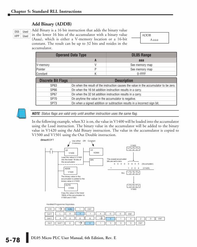
DL05 Micro PLC User Manual, 6th Edition, Rev. E5-78
Chapter 5: Standard RLL Instructions
Add Binary (ADDB)Add Binary is a 16 bit instruction that adds the binary value in the lower 16 bits of the accumulator with a binary value (Aaaa), which is either a V-memory location or a 16-bit constant. The result can be up to 32 bits and resides in the accumulator.
NOTE: Status flags are valid only until another instruction uses the same flag.
In the following example, when X1 is on, the value in V1400 will be loaded into the accumulator using the Load instruction. The binary value in the accumulator will be added to the binary value in V1420 using the Add Binary instruction. The value in the accumulator is copied to V1500 and V1501 using the Out Double instruction.
ADDBA aaa
Discrete Bit Flags DescriptionSP63 On when the result of the instruction causes the value in the accumulator to be zero.SP66 On when the 16 bit addition instruction results in a carry.SP67 On when the 32 bit addition instruction results in a carry.SP70 On anytime the value in the accumulator is negative.SP73 On when a signed addition or subtraction results in a incorrect sign bit.
HandheldProgrammer Keystrokes
LDX1
+ 1
1
(Accumulator)00
1
0 A 0 5
C C 9
0 0 0 A 0 5
2 C 4
Acc. C C 9
STR X(IN) 1
D V 1 4 0 0
OUT V 1 5 0 0
V 1 4 0A 2SHFT B
The unused accumulatorbits are set to zero
SHFT D
ENT
SHFT L ENT
D D ENT
ENT
Load the value in V1400into the lower 16 bits ofthe accumulator
LD
BIN
ADDB
OUTDV1500
K2565
Use either OR ConstantV-memory
V1420
V1400
(V1420)
V1500
V1400
The binary value in theaccumulator is added to thebinary value in V1420
Copy the value in the lower16bits of the accumulator toV1500 and V1501
DirectSOFT 5
Operand Data Type DL05 Range ⸠⸠⸠⸠⸠⸠⸠⸠⸠⸠⸠⸠⸠⸠⸠⸠⸠⸠⸠⸠⸠⸠⸠⸠⸠⸠⸠⸠⸠⸠⸠⸠⸠⸠⸠⸠⸠⸠⸠⸠⸠⸠⸠⸠⸠⸠⸠⸠⸠⸠⸠⸠⸠⸠⸠⸠⸠⸠⸠⸠⸠⸠⸠⸠⸠⸠⸠⸠⸠⸠⸠⸠⸠A aaaV-memory ⸠⸠⸠⸠⸠⸠⸠⸠⸠⸠⸠⸠⸠⸠⸠⸠⸠⸠⸠⸠⸠⸠⸠⸠⸠⸠⸠⸠⸠⸠⸠⸠⸠⸠⸠⸠⸠⸠⸠⸠⸠⸠⸠⸠⸠⸠⸠⸠⸠⸠⸠⸠⸠⸠⸠⸠⸠⸠V See memory mapPointer ⸠⸠⸠⸠⸠⸠⸠⸠⸠⸠⸠⸠⸠⸠⸠⸠⸠⸠⸠⸠⸠⸠⸠⸠⸠⸠⸠⸠⸠⸠⸠⸠⸠⸠⸠⸠⸠⸠⸠⸠⸠⸠⸠⸠⸠⸠⸠⸠⸠⸠⸠⸠⸠⸠⸠⸠⸠⸠⸠⸠⸠⸠⸠⸠P See memory mapConstant ⸠⸠⸠⸠⸠⸠⸠⸠⸠⸠⸠⸠⸠⸠⸠⸠⸠⸠⸠⸠⸠⸠⸠⸠⸠⸠⸠⸠⸠⸠⸠⸠⸠⸠⸠⸠⸠⸠⸠⸠⸠⸠⸠⸠⸠⸠⸠⸠⸠⸠⸠⸠⸠⸠⸠⸠⸠⸠⸠⸠⸠K 0–FFFF
DS5 Used
HPP Used
DirectSOFT
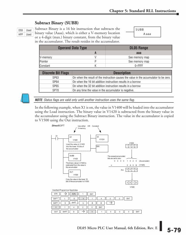
DL05 Micro PLC User Manual, 6th Edition, Rev. E 5-79
Chapter 5: Standard RLL Instructions
Subtract Binary (SUBB)Subtract Binary is a 16 bit instruction that subtracts the binary value (Aaaa), which is either a V-memory location or a 4-digit (max.) binary constant, from the binary value in the accumulator. The result resides in the accumulator.
NOTE: Status flags are valid only until another instruction uses the same flag.
In the following example, when X1 is on, the value in V1400 will be loaded into the accumulator using the Load instruction. The binary value in V1420 is subtracted from the binary value in the accumulator using the Subtract Binary instruction. The value in the accumulator is copied to V1500 using the Out instruction.
S UBB
A aaa
DirectSOFT32 Display
Handheld Programmer Keystrokes
LDV1400
X1
SUBBV1420
The binary value in V1420 issubtracted from the value inthe accumulator
OUTV1500
Copy the value in the lower 16bits of the accumulator to V1500
V1500
(V1420)
0
1 (Accumulator)
0
1
0
0
V14000 2 4
6 1 9
0 0 0 0 2 4
A 0 B
Acc. 6 1 9
The unused accumulatorbits are set to zero
STR X(IN) 1
D V 1 4 0 0
OUT V 1 5 0 0
V 1 4 0
S
2
SHFT B
SHFT D
ENT
SHFT L ENT
U B
ENT
ENT
SHFT
Use either OR ConstantV-memory
LD
BIN
K1024
Load the value in V1400into the lower 16 bits ofthe accumulator
-
Operand Data Type DL05 Range ⸠⸠⸠⸠⸠⸠⸠⸠⸠⸠⸠⸠⸠⸠⸠⸠⸠⸠⸠⸠⸠⸠⸠⸠⸠⸠⸠⸠⸠⸠⸠⸠⸠⸠⸠⸠⸠⸠⸠⸠⸠⸠⸠⸠⸠⸠⸠⸠⸠⸠⸠⸠⸠⸠⸠⸠⸠⸠⸠⸠⸠⸠⸠⸠⸠⸠⸠⸠⸠⸠⸠⸠⸠A aaaV-memory ⸠⸠⸠⸠⸠⸠⸠⸠⸠⸠⸠⸠⸠⸠⸠⸠⸠⸠⸠⸠⸠⸠⸠⸠⸠⸠⸠⸠⸠⸠⸠⸠⸠⸠⸠⸠⸠⸠⸠⸠⸠⸠⸠⸠⸠⸠⸠⸠⸠⸠⸠⸠⸠⸠⸠⸠⸠⸠V See memory mapPointer ⸠⸠⸠⸠⸠⸠⸠⸠⸠⸠⸠⸠⸠⸠⸠⸠⸠⸠⸠⸠⸠⸠⸠⸠⸠⸠⸠⸠⸠⸠⸠⸠⸠⸠⸠⸠⸠⸠⸠⸠⸠⸠⸠⸠⸠⸠⸠⸠⸠⸠⸠⸠⸠⸠⸠⸠⸠⸠⸠⸠⸠⸠⸠⸠P See memory mapConstant ⸠⸠⸠⸠⸠⸠⸠⸠⸠⸠⸠⸠⸠⸠⸠⸠⸠⸠⸠⸠⸠⸠⸠⸠⸠⸠⸠⸠⸠⸠⸠⸠⸠⸠⸠⸠⸠⸠⸠⸠⸠⸠⸠⸠⸠⸠⸠⸠⸠⸠⸠⸠⸠⸠⸠⸠⸠⸠⸠⸠⸠K 0–FFFF
Discrete Bit Flags DescriptionSP63 On when the result of the instruction causes the value in the accumulator to be zero.SP64 On when the 16 bit addition instruction results in a borrowSP65 On when the 32 bit addition instruction results in a borrowSP70 On any time the value in the accumulator is negative.
DS5 Used
HPP Used
DirectSOFT
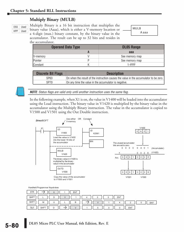
DL05 Micro PLC User Manual, 6th Edition, Rev. E5-80
Chapter 5: Standard RLL Instructions
Multiply Binary (MULB)Multiply Binary is a 16 bit instruction that multiplies the binary value (Aaaa), which is either a V-memory location or a 4-digit (max.) binary constant, by the binary value in the accumulator. The result can be up to 32 bits and resides in the accumulator.
NOTE: Status flags are valid only until another instruction uses the same flag.
In the following example, when X1 is on, the value in V1400 will be loaded into the accumulator using the Load instruction. The binary value in V1420 is multiplied by the binary value in the accumulator using the Multiply Binary instruction. The value in the accumulator is copied to V1500 and V1501 using the Out Double instruction.
MULBA aaa
DirectSOFT32 Display
Handheld Programmer Keystrokes
LDV1400
X1
MULBV1420
The binary value in V1420 ismultiplied by the binaryvalue in the accumulator
OUTDV1500
0 (Accumulator)
0
0
0
(V1420)
V1400A 0 1
0 0 0 A 0 1
0 2 E
The unused accumulatorbits are set to zero
2 E0 0 0 1 C
C
C
V1500
C 2 E
V1501
0 0 0 1
Acc.
STR X 1
D V 1 4 0 0
OUT V 1 5 0 0
V 1 4 0M 2SHFT B
SHFT D
ENT
SHFT L ENT
U L ENT
ENT
Copy the value of the accumulatorto V1500 and V1501
Use either OR ConstantV-memory
LD
BIN
K2561
Load the value in V1400into the lower 16 bits ofthe accumulator
x
Operand Data Type DL05 Range ⸠⸠⸠⸠⸠⸠⸠⸠⸠⸠⸠⸠⸠⸠⸠⸠⸠⸠⸠⸠⸠⸠⸠⸠⸠⸠⸠⸠⸠⸠⸠⸠⸠⸠⸠⸠⸠⸠⸠⸠⸠⸠⸠⸠⸠⸠⸠⸠⸠⸠⸠⸠⸠⸠⸠⸠⸠⸠⸠⸠⸠⸠⸠⸠⸠⸠⸠⸠⸠⸠⸠⸠⸠A aaaV-memory ⸠⸠⸠⸠⸠⸠⸠⸠⸠⸠⸠⸠⸠⸠⸠⸠⸠⸠⸠⸠⸠⸠⸠⸠⸠⸠⸠⸠⸠⸠⸠⸠⸠⸠⸠⸠⸠⸠⸠⸠⸠⸠⸠⸠⸠⸠⸠⸠⸠⸠⸠⸠⸠⸠⸠⸠⸠⸠V See memory mapPointer ⸠⸠⸠⸠⸠⸠⸠⸠⸠⸠⸠⸠⸠⸠⸠⸠⸠⸠⸠⸠⸠⸠⸠⸠⸠⸠⸠⸠⸠⸠⸠⸠⸠⸠⸠⸠⸠⸠⸠⸠⸠⸠⸠⸠⸠⸠⸠⸠⸠⸠⸠⸠⸠⸠⸠⸠⸠⸠⸠⸠⸠⸠⸠⸠P See memory mapConstant ⸠⸠⸠⸠⸠⸠⸠⸠⸠⸠⸠⸠⸠⸠⸠⸠⸠⸠⸠⸠⸠⸠⸠⸠⸠⸠⸠⸠⸠⸠⸠⸠⸠⸠⸠⸠⸠⸠⸠⸠⸠⸠⸠⸠⸠⸠⸠⸠⸠⸠⸠⸠⸠⸠⸠⸠⸠⸠⸠⸠⸠K 1–FFFF
Discrete Bit Flags DescriptionSP63 On when the result of the instruction causes the value in the accumulator to be zero.SP70 On any time the value in the accumulator is negative.
DS5 Used
HPP Used
DirectSOFT
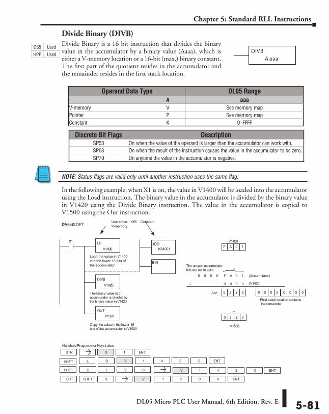
DL05 Micro PLC User Manual, 6th Edition, Rev. E 5-81
Chapter 5: Standard RLL Instructions
Divide Binary (DIVB)Divide Binary is a 16 bit instruction that divides the binary value in the accumulator by a binary value (Aaaa), which is either a V-memory location or a 16-bit (max.) binary constant. The first part of the quotient resides in the accumulator and the remainder resides in the first stack location.
NOTE: Status flags are valid only until another instruction uses the same flag.
In the following example, when X1 is on, the value in V1400 will be loaded into the accumulator using the Load instruction. The binary value in the accumulator is divided by the binary value in V1420 using the Divide Binary instruction. The value in the accumulator is copied to V1500 using the Out instruction.
DIVB
A aaa
DirectSOFT32 Display
Handheld Programmer Keystrokes
LDV1400
X1
DIVBV1420
The binary value in thaccumulator is divided bythe binary value in V1420
OUTV1500
Copy the value in the lower 16bits of the accumulator to V1500
V1500
0 (Accumulator)F
0
0
F
(V1420)
0
V1400A 0 1
3 2 0
0 0 0 A 0 1
0 5 0
Acc. 3 2 0
The unused accumulatorbits are set to zero
0 0 00 0 0 0 0
First stack location containsthe remainder
STR X 1
D V 1 4 0 0
OUT V 1 5 0 0
V 1 4 0D 2SHFT B
SHFT D
ENT
SHFT L ENT
I V ENT
ENT
_..
Use either OR ConstantV-memory
LDD
BIN
K64001
Load the value in V1400into the lower 16 bits ofthe accumulator
Operand Data Type DL05 Range ⸠⸠⸠⸠⸠⸠⸠⸠⸠⸠⸠⸠⸠⸠⸠⸠⸠⸠⸠⸠⸠⸠⸠⸠⸠⸠⸠⸠⸠⸠⸠⸠⸠⸠⸠⸠⸠⸠⸠⸠⸠⸠⸠⸠⸠⸠⸠⸠⸠⸠⸠⸠⸠⸠⸠⸠⸠⸠⸠⸠⸠⸠⸠⸠⸠⸠⸠⸠⸠⸠⸠⸠⸠A aaaV-memory ⸠⸠⸠⸠⸠⸠⸠⸠⸠⸠⸠⸠⸠⸠⸠⸠⸠⸠⸠⸠⸠⸠⸠⸠⸠⸠⸠⸠⸠⸠⸠⸠⸠⸠⸠⸠⸠⸠⸠⸠⸠⸠⸠⸠⸠⸠⸠⸠⸠⸠⸠⸠⸠⸠⸠⸠⸠⸠V See memory mapPointer ⸠⸠⸠⸠⸠⸠⸠⸠⸠⸠⸠⸠⸠⸠⸠⸠⸠⸠⸠⸠⸠⸠⸠⸠⸠⸠⸠⸠⸠⸠⸠⸠⸠⸠⸠⸠⸠⸠⸠⸠⸠⸠⸠⸠⸠⸠⸠⸠⸠⸠⸠⸠⸠⸠⸠⸠⸠⸠⸠⸠⸠⸠⸠⸠P See memory mapConstant ⸠⸠⸠⸠⸠⸠⸠⸠⸠⸠⸠⸠⸠⸠⸠⸠⸠⸠⸠⸠⸠⸠⸠⸠⸠⸠⸠⸠⸠⸠⸠⸠⸠⸠⸠⸠⸠⸠⸠⸠⸠⸠⸠⸠⸠⸠⸠⸠⸠⸠⸠⸠⸠⸠⸠⸠⸠⸠⸠⸠⸠K 0–FFFF
Discrete Bit Flags DescriptionSP53 On when the value of the operand is larger than the accumulator can work with.SP63 On when the result of the instruction causes the value in the accumulator to be zero.SP70 On anytime the value in the accumulator is negative.
DS5 Used
HPP Used
DirectSOFT
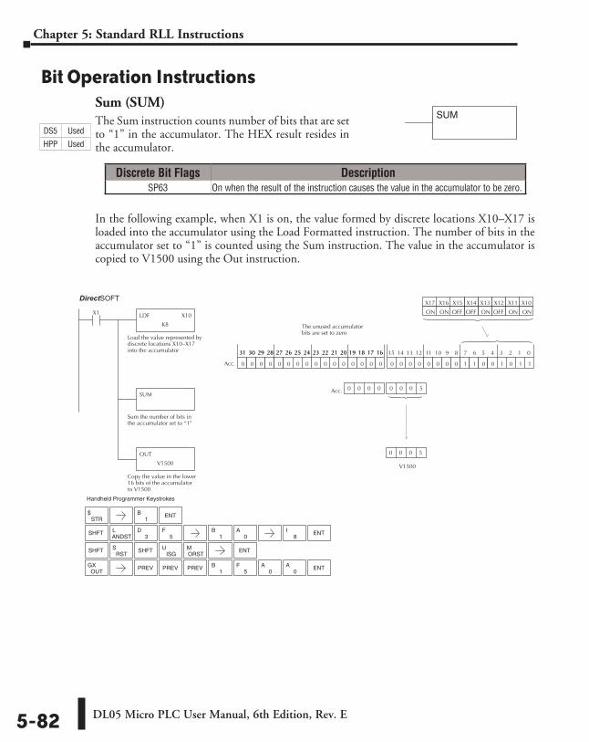
DL05 Micro PLC User Manual, 6th Edition, Rev. E5-82
Chapter 5: Standard RLL Instructions
Bit Operation InstructionsSum (SUM)The Sum instruction counts number of bits that are set to “1” in the accumulator. The HEX result resides in the accumulator.
In the following example, when X1 is on, the value formed by discrete locations X10–X17 is loaded into the accumulator using the Load Formatted instruction. The number of bits in the accumulator set to “1” is counted using the Sum instruction. The value in the accumulator is copied to V1500 using the Out instruction.
SUM
Direct SOFT32 Display
LDF X10
K8
X1
Load the value represented bydiscrete locations X10–X17into the accumulator
SUM
Sum the number of bits inthe accumulator set to “1”
OUT
V1500
Copy the value in the lower16 bits of the accumulatorto V1500
X10X11X12X13
ONONOFFON
X14X15X16X17
OFFOFFONON
0 0 0 0 0 0 0 0 1 1 0 0 1 0 1 10 0 0 0 0 0 0 0 0 0 0 0 0 0 0 0
15 14 13 12 11 10 9 8 7 6 5 4 3 2 1 031 30 29 28 27 26 25 24 23 22 21 20 19 18 17 1631 30 29 28 27 26 25 24 23 22 21 20 19 18 17 16
Acc.
V1500
Acc.
0 0 0 5
0 0 0 0 0 0 0 5
The unused accumulatorbits are set to zero
STR$ ENT
SHFTANDSTL
3D
5F
SHFTRST
SISG
UORSTM ENT
1B
1B
0A
8I ENT
SHFT
OUTGX PREV
1B
5F
0A
0A ENTPREV PREV
Handheld Programmer Keystrokes
Discrete Bit Flags DescriptionSP63 On when the result of the instruction causes the value in the accumulator to be zero.
DS5 Used
HPP Used
DirectSOFT
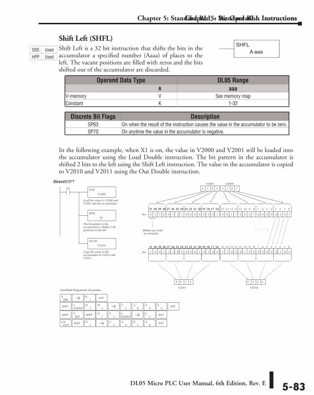
DL05 Micro PLC User Manual, 6th Edition, Rev. E 5-83
Chapter 5: Standard RLL Instructions
Shift Left (SHFL)Shift Left is a 32 bit instruction that shifts the bits in the accumulator a specified number (Aaaa) of places to the left. The vacant positions are filled with zeros and the bits shifted out of the accumulator are discarded.
In the following example, when X1 is on, the value in V2000 and V2001 will be loaded into the accumulator using the Load Double instruction. The bit pattern in the accumulator is shifted 2 bits to the left using the Shift Left instruction. The value in the accumulator is copied to V2010 and V2011 using the Out Double instruction.
Chapter 5: Standard RLL - Bit Operation Instructions
2C ENT
Handheld Programmer Keystrokes
Direct SOFT32
LDD
V2000
X1
Load the value in V2000 andV2001 into the accumulator
SHFL
K2
The bit pattern in theaccumulator is shifted 2 bitpositions to the left
OUTD
V2010
Copy the value in theaccumulator to V2010 andV2011
0 0 1 1 0 0 0 1 0 0 0 0 0 0 0 1
V2010
1 1 0 0 0 1 0 0 0 0 0 0 0 1 0 00 0 0 0 0 1 0 0 0 0 0 0 0 0 0 0
15 14 13 12 11 10 9 8 7 6 5 4 3 2 1 031 30 29 28 27 26 25 24 23 22 21 20 19 18 17 16
C 4 0 4
. . . .
1 0 0 1 1 1 0 0 0 0 0 1 0 1 0 0
31 30 29 28 27 26 25 24 23 22 21 20 19 18 17 16
0 1 1 0 0 1 1 1 0 0 0 0 0 1 0 1
15 14 13 12 11 10 9 8 7 6 5 4 3 2 1 031 30 29 28 27 26 25 24 23 22 21 20 19 18 17 1631 30 29 28 27 26 25 24 23 22 21 20 19 18 17 16
Acc.
Acc.
V2011
9 C 1 4
6 7 0 5 3 3 1 0 3 1 0 1
Shifted out of the accumulator
V2000V2001
STR$
SHFTANDSTL
3D
3D
SHFTRST
S7
H5
FANDSTL
OUTGX SHFT
3D
1B ENT
2C
0A
0A
0A ENT
2C
0A
1B
0A ENT
SHFT
Operand Data Type DL05 Range ⸠⸠⸠⸠⸠⸠⸠⸠⸠⸠⸠⸠⸠⸠⸠⸠⸠⸠⸠⸠⸠⸠⸠⸠⸠⸠⸠⸠⸠⸠⸠⸠⸠⸠⸠⸠⸠⸠⸠⸠⸠⸠⸠⸠⸠⸠⸠⸠⸠⸠⸠⸠⸠⸠⸠⸠⸠⸠⸠⸠⸠⸠⸠⸠⸠⸠⸠⸠⸠⸠⸠⸠⸠A aaaV-memory ⸠⸠⸠⸠⸠⸠⸠⸠⸠⸠⸠⸠⸠⸠⸠⸠⸠⸠⸠⸠⸠⸠⸠⸠⸠⸠⸠⸠⸠⸠⸠⸠⸠⸠⸠⸠⸠⸠⸠⸠⸠⸠⸠⸠⸠⸠⸠⸠⸠⸠⸠⸠⸠⸠⸠⸠⸠⸠V See memory mapConstant ⸠⸠⸠⸠⸠⸠⸠⸠⸠⸠⸠⸠⸠⸠⸠⸠⸠⸠⸠⸠⸠⸠⸠⸠⸠⸠⸠⸠⸠⸠⸠⸠⸠⸠⸠⸠⸠⸠⸠⸠⸠⸠⸠⸠⸠⸠⸠⸠⸠⸠⸠⸠⸠⸠⸠⸠⸠⸠⸠⸠⸠K 1-32
Discrete Bit Flags DescriptionSP63 On when the result of the instruction causes the value in the accumulator to be zero.SP70 On anytime the value in the accumulator is negative.
SHFLA aaaDS5 Used
HPP Used
DirectSOFT
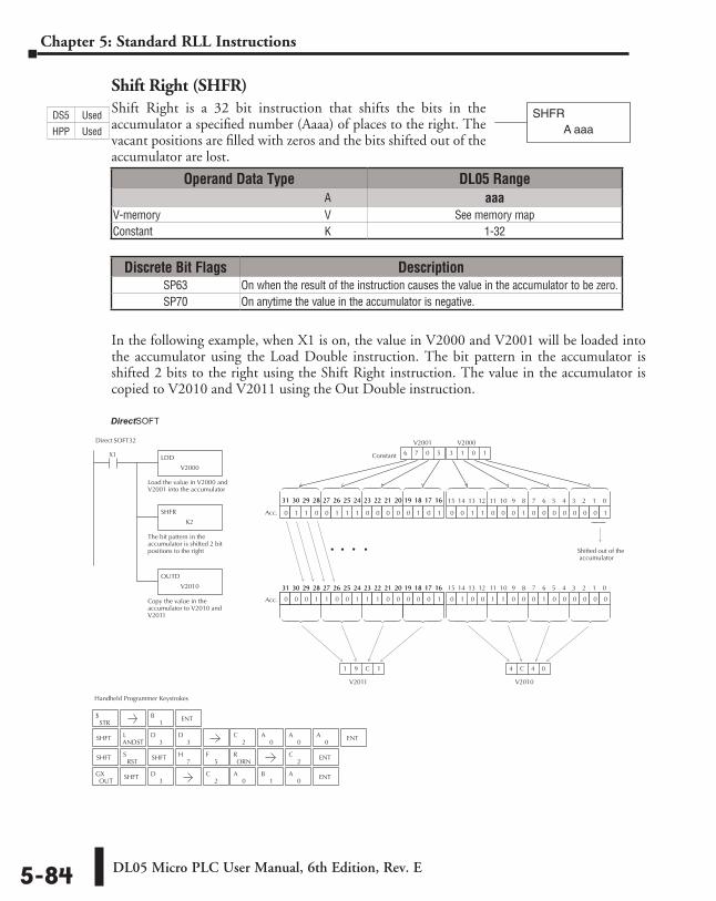
DL05 Micro PLC User Manual, 6th Edition, Rev. E5-84
Chapter 5: Standard RLL Instructions
Shift Right (SHFR)Shift Right is a 32 bit instruction that shifts the bits in the accumulator a specified number (Aaaa) of places to the right. The vacant positions are filled with zeros and the bits shifted out of the accumulator are lost.
In the following example, when X1 is on, the value in V2000 and V2001 will be loaded into the accumulator using the Load Double instruction. The bit pattern in the accumulator is shifted 2 bits to the right using the Shift Right instruction. The value in the accumulator is copied to V2010 and V2011 using the Out Double instruction.
SHFRA aaa
Handheld Programmer Keystrokes
Direct SOFT32
LDD
V2000
X1
Load the value in V2000 andV2001 into the accumulator
SHFR
K2
The bit pattern in theaccumulator is shifted 2 bitpositions to the right
OUTD
V2010
Copy the value in theaccumulator to V2010 andV2011
0 0 1 1 0 0 0 1 0 0 0 0 0 0 0 1
V2010
0 1 0 0 1 1 0 0 0 1 0 0 0 0 0 00 0 0 0 0 1 0 0 0 0 0 0 0 0 0 0
15 14 13 12 11 10 9 8 7 6 5 4 3 2 1 031 30 29 28 27 26 25 24 23 22 21 20 19 18 17 16
4 C 4 0
. . .
0 0 0 1 1 0 0 1 1 1 0 0 0 0 0 1
31 30 29 28 27 26 25 24 23 22 21 20 19 18 17 16
0 1 1 0 0 1 1 1 0 0 0 0 0 1 0 1
15 14 13 12 11 10 9 8 7 6 5 4 3 2 1 031 30 29 28 27 26 25 24 23 22 21 20 19 18 17 1631 30 29 28 27 26 25 24 23 22 21 20 19 18 17 16
Acc.
Acc.
V2011
1 9 C 1
Constant 6 7 0 5 3 1 0 1 3 1 0 1
Shifted out of the accumulator
V2001 V2000
STR$
SHFTANDSTL
3D
3D
SHFTRST
S7
H5
F2
C ENT
OUTGX SHFT
3D
ORNRSHFT
1B ENT
2C
0A
0A
0A ENT
2C
0A
1B
0A ENT
.
Operand Data Type DL05 Range ⸠⸠⸠⸠⸠⸠⸠⸠⸠⸠⸠⸠⸠⸠⸠⸠⸠⸠⸠⸠⸠⸠⸠⸠⸠⸠⸠⸠⸠⸠⸠⸠⸠⸠⸠⸠⸠⸠⸠⸠⸠⸠⸠⸠⸠⸠⸠⸠⸠⸠⸠⸠⸠⸠⸠⸠⸠⸠⸠⸠⸠⸠⸠⸠⸠⸠⸠⸠⸠⸠⸠⸠⸠A aaaV-memory ⸠⸠⸠⸠⸠⸠⸠⸠⸠⸠⸠⸠⸠⸠⸠⸠⸠⸠⸠⸠⸠⸠⸠⸠⸠⸠⸠⸠⸠⸠⸠⸠⸠⸠⸠⸠⸠⸠⸠⸠⸠⸠⸠⸠⸠⸠⸠⸠⸠⸠⸠⸠⸠⸠⸠⸠⸠⸠V See memory mapConstant ⸠⸠⸠⸠⸠⸠⸠⸠⸠⸠⸠⸠⸠⸠⸠⸠⸠⸠⸠⸠⸠⸠⸠⸠⸠⸠⸠⸠⸠⸠⸠⸠⸠⸠⸠⸠⸠⸠⸠⸠⸠⸠⸠⸠⸠⸠⸠⸠⸠⸠⸠⸠⸠⸠⸠⸠⸠⸠⸠⸠⸠K 1-32
Discrete Bit Flags DescriptionSP63 On when the result of the instruction causes the value in the accumulator to be zero.SP70 On anytime the value in the accumulator is negative.
DS5 Used
HPP Used
DirectSOFT
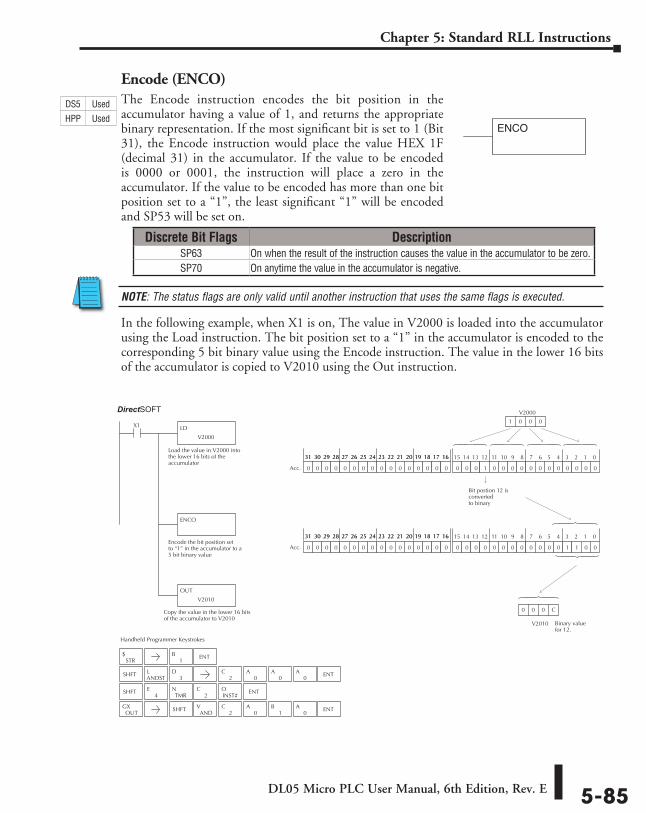
DL05 Micro PLC User Manual, 6th Edition, Rev. E 5-85
Chapter 5: Standard RLL Instructions
Encode (ENCO)The Encode instruction encodes the bit position in the accumulator having a value of 1, and returns the appropriate binary representation. If the most significant bit is set to 1 (Bit 31), the Encode instruction would place the value HEX 1F (decimal 31) in the accumulator. If the value to be encoded is 0000 or 0001, the instruction will place a zero in the accumulator. If the value to be encoded has more than one bit position set to a “1”, the least significant “1” will be encoded and SP53 will be set on.
NOTE: The status flags are only valid until another instruction that uses the same flags is executed.
In the following example, when X1 is on, The value in V2000 is loaded into the accumulator using the Load instruction. The bit position set to a “1” in the accumulator is encoded to the corresponding 5 bit binary value using the Encode instruction. The value in the lower 16 bits of the accumulator is copied to V2010 using the Out instruction.
ENCO
Handheld Programmer Keystrokes
Direct SOFT32
LD
V2000
X1
Load the value in V2000 intothe lower 16 bits of theaccumulator
ENCO
Encode the bit position setto “1” in the accumulator to a5 bit binary value
0 0 0 1 0 0 0 0 0 0 0 0 0 0 0 00 0 0 0 0 0 0 0 0 0 0 0 0 0 0 0
15 14 13 12 11 10 9 8 7 6 5 4 3 2 1 031 30 29 28 27 26 25 24 23 22 21 20 19 18 17 1631 30 29 28 27 26 25 24 23 22 21 20 19 18 17 16
Acc.
0 0 0 0 0 0 0 0 0 0 0 0 1 1 0 00 0 0 0 0 0 0 0 0 0 0 0 0 0 0 0
15 14 13 12 11 10 9 8 7 6 5 4 3 2 1 031 30 29 28 27 26 25 24 23 22 21 20 19 18 17 1631 30 29 28 27 26 25 24 23 22 21 20 19 18 17 16
Acc.
V2000
1 0 0 0
Bit postion 12 isconverted to binary
Copy the value in the lower 16 bitsof the accumulator to V2010
OUT
V2010
V2010
0 0 0 C
Binary valuefor 12.
STR$
1B ENT
SHFT
OUTGX SHFT
ANDV
2C
0A
1B
0A ENT
4E
TMRN
2C
INST#O ENT
SHFTANDSTL
3D
2C
0A
0A
0A ENT
Discrete Bit Flags DescriptionSP63 On when the result of the instruction causes the value in the accumulator to be zero.SP70 On anytime the value in the accumulator is negative.
DS5 Used
HPP Used
DirectSOFT
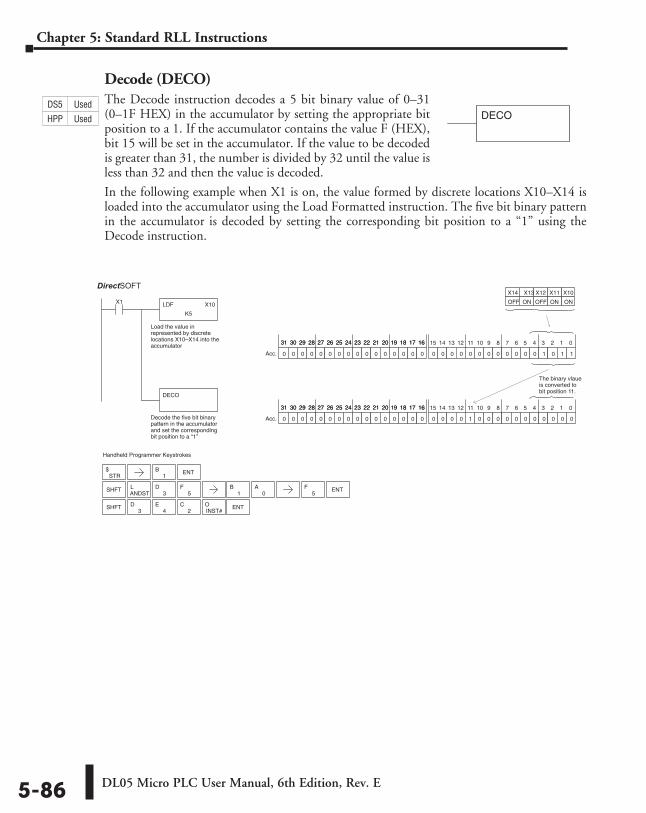
DL05 Micro PLC User Manual, 6th Edition, Rev. E5-86
Chapter 5: Standard RLL Instructions
Decode (DECO)The Decode instruction decodes a 5 bit binary value of 0–31 (0–1F HEX) in the accumulator by setting the appropriate bit position to a 1. If the accumulator contains the value F (HEX), bit 15 will be set in the accumulator. If the value to be decoded is greater than 31, the number is divided by 32 until the value is less than 32 and then the value is decoded.
In the following example when X1 is on, the value formed by discrete locations X10–X14 is loaded into the accumulator using the Load Formatted instruction. The five bit binary pattern in the accumulator is decoded by setting the corresponding bit position to a “1” using the Decode instruction.
Handheld Programmer Keystrokes
Direct SOFT32
LDF X10
K5
X1
Load the value inrepresented by discretelocations X10–X14 into theaccumulator
DECO
Decode the five bit binarypattern in the accumulatorand set the correspondingbit position to a “1”
X10 X11 X13 X12
ON ON OFF
X14
OFF ON
0 0 0 0 0 0 0 0 0 0 0 0 1 0 1 10 0 0 0 0 0 0 0 0 0 0 0 0 0 0 0
15 14 13 12 11 10 9 8 7 6 5 4 3 2 1 031 30 29 28 27 26 25 24 23 22 21 20 19 18 17 1631 30 29 28 27 26 25 24 23 22 21 20 19 18 17 16
Acc.
0 0 0 0 1 0 0 0 0 0 0 0 0 0 0 00 0 0 0 0 0 0 0 0 0 0 0 0 0 0 0
15 14 13 12 11 10 9 8 7 6 5 4 3 2 1 031 30 29 28 27 26 25 24 23 22 21 20 19 18 17 1631 30 29 28 27 26 25 24 23 22 21 20 19 18 17 16
Acc.
The binary vlaue is converted tobit position 11.
STR$ ENT
SHFTANDSTL
3D
5F
1B
1B
0A ENT
5F
SHFT2
CINST#O ENT
3D
4E
DECODS5 Used
HPP Used
DirectSOFT
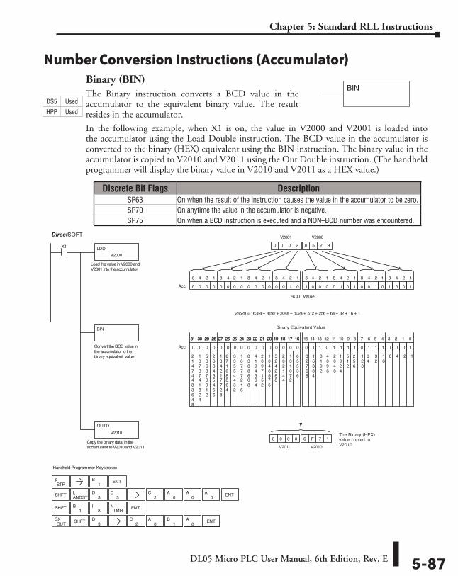
DL05 Micro PLC User Manual, 6th Edition, Rev. E 5-87
Chapter 5: Standard RLL Instructions
Number Conversion Instructions (Accumulator)Binary (BIN)The Binary instruction converts a BCD value in the accumulator to the equivalent binary value. The result resides in the accumulator.
In the following example, when X1 is on, the value in V2000 and V2001 is loaded into the accumulator using the Load Double instruction. The BCD value in the accumulator is converted to the binary (HEX) equivalent using the BIN instruction. The binary value in the accumulator is copied to V2010 and V2011 using the Out Double instruction. (The handheld programmer will display the binary value in V2010 and V2011 as a HEX value.)
BIN
Standard
RLL
Instructions
STR$
0A
OUTGX SHFT
3D
2C
0A
1B ENT
0 0 0 0 6 F 7 1
V2010V2011
Handheld Programmer Keystrokes
DirectSOFT32
LDD
V2000
X1
BIN
1 0 0 0 0 1 0 1 0 0 1 0 1 0 0 10 0 0 0 0 0 0 0 0 0 0 0 0 0 1 0
8 4 2 1 8 4 2 1 8 4 2 1 8 4 2 18 4 2 1 8 4 2 1 8 4 2 1 8 4 2 1
Acc.
0 0 0 2 8 5 2 9
V2000V2001
0 1 1 0 1 1 1 1 0 1 1 1 0 0 0 10 0 0 0 0 0 0 0 0 0 0 0 0 0 0 0
15 14 13 12 11 10 9 8 7 6 5 4 3 2 1 031 30 29 28 27 26 25 24 23 22 21 20 19 18 17 1631 30 29 28 27 26 25 24 23 22 21 20 19 18 17 16
Acc.
124816
32
64
128
256
512
1024
2048
4096
8192
16384
32768
65536
131072
262144
524288
1048576
2097152
4194304
8388608
16777216
33554432
67108864
134217728
268435456
536870912
1073741824
21474483648
OUTD
V2010
28529 = 16384 + 8192 + 2048 + 1024 + 512 + 256 + 64 + 32 + 16 + 1
1B ENT
SHFTANDSTL
3D
3D
2C
0A
0A
0A ENT
SHFT1
B8
ITMR
N ENT
Copy the binary data in theaccumulator to V2010 and V2011
Convert the BCD value in the accumulator to the binary equivalent value
Load the value in V2000 andV2001 into the accumulator
BCD Value
Binary Equivalent Value
The Binary (HEX)value copied toV2010
Discrete Bit Flags DescriptionSP63 On when the result of the instruction causes the value in the accumulator to be zero.SP70 On anytime the value in the accumulator is negative.SP75 On when a BCD instruction is executed and a NON–BCD number was encountered.
DS5 Used
HPP Used
DirectSOFT
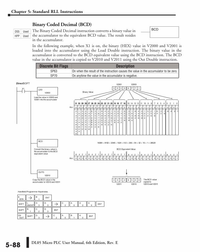
DL05 Micro PLC User Manual, 6th Edition, Rev. E5-88
Chapter 5: Standard RLL Instructions
Binary Coded Decimal (BCD)The Binary Coded Decimal instruction converts a binary value in the accumulator to the equivalent BCD value. The result resides in the accumulator.
In the following example, when X1 is on, the binary (HEX) value in V2000 and V2001 is loaded into the accumulator using the Load Double instruction. The binary value in the accumulator is converted to the BCD equivalent value using the BCD instruction. The BCD value in the accumulator is copied to V2010 and V2011 using the Out Double instruction.
BCD
3D
Handheld Programmer Keystrokes
DirectSOFT32
LDD
V2000
X1
Load the value in V2000 andV2001 into the accumulator
BCD
Convert the binary value inthe accumulator to the BCDequivalent value
0 1 1 0 1 1 1 1 0 1 1 1 0 0 0 10 0 0 0 0 0 0 0 0 0 0 0 0 0 0 0
15 14 13 12 11 10 9 8 7 6 5 4 3 2 1 031 30 29 28 27 26 25 24 23 22 21 20 19 18 17 1631 30 29 28 27 26 25 24 23 22 21 20 19 18 17 16
Acc.
0 0 0 0 6 F 7 1
V2000V2001
BCD Equivalent Value
Binary Value
1 0 0 0 0 1 0 1 0 0 1 0 1 0 0 10 0 0 0 0 0 0 0 0 0 0 0 0 0 1 0Acc.
124816
32
64
128
256
512
1024
2048
4096
8192
16384
32768
65536
131072
262144
524288
1048576
2097152
4194304
8388608
16777216
33554432
67108864
134217728
268435456
536870912
1073741824
21474483648
Copy the BCD value in theaccumulator to V2010 and V2011
OUTD
V2010
The BCD valuecopied toV2010 and V2011
0 0 0 2 8 5 2 9
V2010V2011
8 4 2 1 8 4 2 1 8 4 2 1 8 4 2 18 4 2 1 8 4 2 1 8 4 2 1 8 4 2 1
16384 + 8192 + 2048 + 1024 + 512 + 256 + 64 + 32 + 16 + 1 = 28529
STR$
1B ENT
SHFTANDSTL
3D
3D
2C
0A
0A
0A ENT
SHFT1
B ENT
OUTGX SHFT
2C
0A
1B
0A ENT
2C
3D
Discrete Bit Flags DescriptionSP63 On when the result of the instruction causes the value in the accumulator to be zero.SP70 On anytime the value in the accumulator is negative.
DS5 Used
HPP Used
DirectSOFT
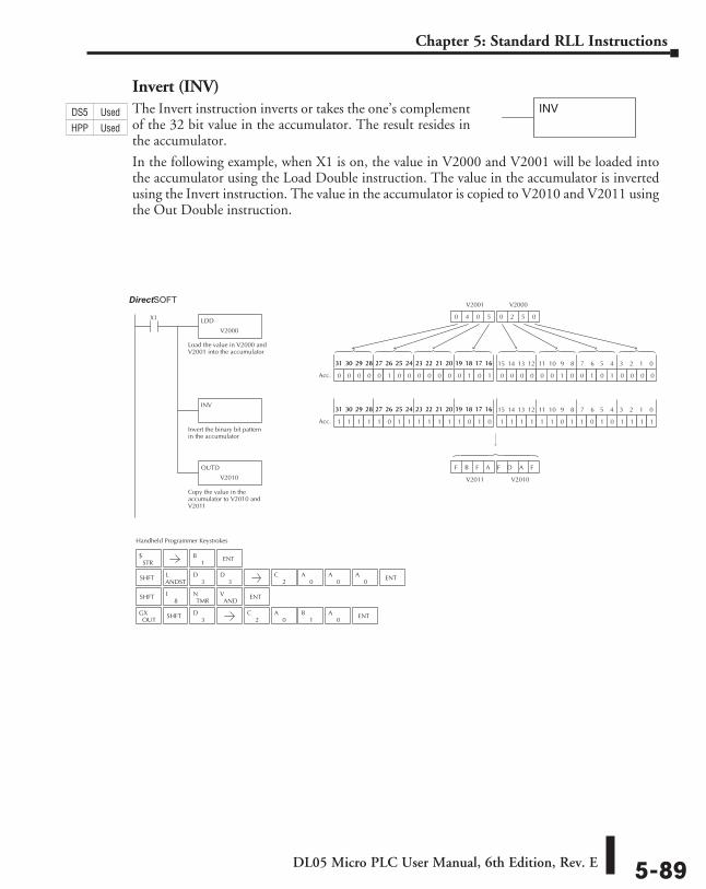
DL05 Micro PLC User Manual, 6th Edition, Rev. E 5-89
Chapter 5: Standard RLL Instructions
Invert (INV)The Invert instruction inverts or takes the one’s complement of the 32 bit value in the accumulator. The result resides in the accumulator.
In the following example, when X1 is on, the value in V2000 and V2001 will be loaded into the accumulator using the Load Double instruction. The value in the accumulator is inverted using the Invert instruction. The value in the accumulator is copied to V2010 and V2011 using the Out Double instruction.
INV
Handheld Programmer Keystrokes
Direct SOFT32
LDD
V2000
X1
Load the value in V2000 andV2001 into the accumulator
INV
Invert the binary bit patternin the accumulator
OUTD
V2010
Copy the value in theaccumulator to V2010 andV2011
0 0 0 0 0 0 1 0 0 1 0 1 0 0 0 00 0 0 0 0 1 0 0 0 0 0 0 0 1 0 1
15 14 13 12 11 10 9 8 7 6 5 4 3 2 1 031 30 29 28 27 26 25 24 23 22 21 20 19 18 17 1631 30 29 28 27 26 25 24 23 22 21 20 19 18 17 16
Acc.
0 4 0 5 0 2 5 0 0 2 5 0
V2000 V2001
V2010 V2011
1 1 1 1 1 1 0 1 1 0 1 0 1 1 1 11 1 1 1 1 0 1 1 1 1 1 1 1 0 1 0
15 14 13 12 11 10 9 8 7 6 5 4 3 2 1 031 30 29 28 27 26 25 24 23 22 21 20 19 18 17 1631 30 29 28 27 26 25 24 23 22 21 20 19 18 17 16
Acc.
F B F A F D A F
STR$
SHFTANDSTL
3D
3D
SHFT ENT
OUTGX SHFT
3D
8I
TMRN
ANDV
1B ENT
2C
0A
0A
0A ENT
2C
0A
1B
0A ENT
DS5 Used
HPP Used
DirectSOFT
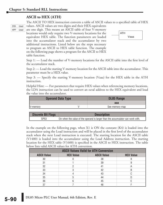
DL05 Micro PLC User Manual, 6th Edition, Rev. E5-90
Chapter 5: Standard RLL Instructions
ASCII to HEX (ATH)The ASCII TO HEX instruction converts a table of ASCII values to a specified table of HEX values. ASCII values are two digits and their HEX equivalents are one digit. This means an ASCII table of four V-memory locations would only require two V-memory locations for the equivalent HEX table. The function parameters are loaded into the accumulator stack and the accumulator by two additional instructions. Listed below are the steps necessary to program an ASCII to HEX table function. The example on the following page shows a program for the ASCII to HEX table function.
Step 1: — Load the number of V-memory locations for the ASCII table into the first level of the accumulator stack.
Step 2: — Load the starting V-memory location for the ASCII table into the accumulator. This parameter must be a HEX value.
Step 3: — Specify the starting V-memory location (Vaaa) for the HEX table in the ATH instruction.
Helpful Hint: — For parameters that require HEX values when referencing memory locations, the LDA instruction can be used to convert an octal address to the HEX equivalent and load the value into the accumulator.
In the example on the following page, when X1 is ON the constant (K4) is loaded into the accumulator using the Load instruction and will be placed in the first level of the accumulator stack when the next Load instruction is executed. The starting location for the ASCII table (V1400) is loaded into the accumulator using the Load Address instruction. The starting location for the HEX table (V1600) is specified in the ASCII to HEX instruction. The table below lists valid ASCII values for ATH conversion.
aaaATH
V
Operand Data Type DL05 Rangeaaa
V-memory ⸠⸠⸠⸠⸠⸠⸠⸠⸠⸠⸠⸠⸠⸠⸠⸠⸠⸠⸠⸠⸠⸠⸠⸠⸠⸠⸠⸠⸠⸠⸠⸠⸠⸠⸠⸠⸠⸠⸠⸠⸠⸠⸠⸠⸠⸠⸠⸠⸠⸠⸠⸠⸠⸠⸠⸠⸠⸠V See memory map
Discrete Bit Flags DescriptionSP53 On when the value of the operand is larger than the accumulator can work with.
ASCII Values Valid for ATH ConversionASCII Value HEX Value ASCII Value HEX Value
30 0 38 831 1 39 932 2 41 A33 3 42 B34 4 43 C35 5 44 D36 6 45 E37 7 46 F
DS5 Used
HPP Used
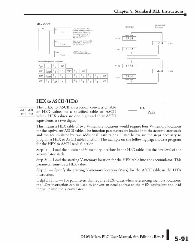
DL05 Micro PLC User Manual, 6th Edition, Rev. E 5-91
Chapter 5: Standard RLL Instructions
HEX to ASCII (HTA)The HEX to ASCII instruction converts a table of HEX values to a specified table of ASCII values. HEX values are one digit and their ASCII equivalents are two digits.
This means a HEX table of two V-memory locations would require four V-memory locations for the equivalent ASCII table. The function parameters are loaded into the accumulator stack and the accumulator by two additional instructions. Listed below are the steps necessary to program a HEX to ASCII table function. The example on the following page shows a program for the HEX to ASCII table function.
Step 1: — Load the number of V-memory locations in the HEX table into the first level of the accumulator stack.
Step 2: — Load the starting V-memory location for the HEX table into the accumulator. This parameter must be a HEX value.
Step 3: — Specify the starting V-memory location (Vaaa) for the ASCII table in the HTA instruction.
Helpful Hint: — For parameters that require HEX values when referencing memory locations, the LDA instruction can be used to convert an octal address to the HEX equivalent and load the value into the accumulator.
Direct SOFT32
LD
K4
X1 Load the constant valueinto the lower 16 bits of theaccumulator. This valuedefines the number of Vmemory location in theASCII table
LDA
O 1400
Convert octal 1400 to HEX300 and load the value intothe accumulator
ATH
V1600
V1600 is the startinglocation for the HEX table
ASCII TABLEHexadecimal Equivalents
1234
33 34V1400
5678
31 32V1401
37 38V1402
35 36V1403
V1600
V1601
STR$
SHFTANDSTL
3D
7H
SHFT
MLRTSHFT
1B ENT
ENT
4E
0A
0A
ENT
1B
6G
0A
0A
Handheld Programmer Keystrokes
PREV
ANDSTL
3D ENT
1B
4E
0A
0A
aaaVHTADS5 Used
HPP Used
DirectSOFT
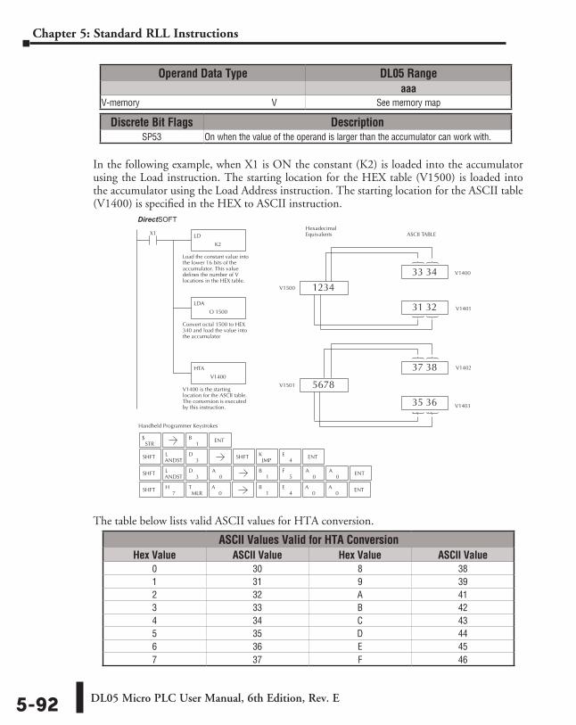
DL05 Micro PLC User Manual, 6th Edition, Rev. E5-92
Chapter 5: Standard RLL Instructions
In the following example, when X1 is ON the constant (K2) is loaded into the accumulator using the Load instruction. The starting location for the HEX table (V1500) is loaded into the accumulator using the Load Address instruction. The starting location for the ASCII table (V1400) is specified in the HEX to ASCII instruction.
The table below lists valid ASCII values for HTA conversion.
Direct SOFT32
Handheld Programmer Keystrokes
LD
K2
X1
Load the constant value intothe lower 16 bits of theaccumulator. This valuedefines the number of Vlocations in the HEX table.
LDA
O 1500
Convert octal 1500 to HEX340 and load the value intothe accumulator
HTA
V1400
V1400 is the startinglocation for the ASCII table.The conversion is executedby this instruction.
ASCII TABLEHexadecimal Equivalents
1234
33 34 V1400
5678
31 32 V1401
37 38 V1402
35 36 V1403
V1500
V1501
STR$
SHFTANDSTL
3D SHFT
JMPK
4E ENT
SHFTANDSTL
3D
0A
0A
0A ENT
SHFT
1B ENT
0A
0A ENT
1B
5F
0A
MLRT
7H
1B
4E
ASCII Values Valid for HTA ConversionHex Value ASCII Value Hex Value ASCII Value
0 30 8 381 31 9 392 32 A 413 33 B 424 34 C 435 35 D 446 36 E 457 37 F 46
Operand Data Type DL05 Rangeaaa
V-memory ⸠⸠⸠⸠⸠⸠⸠⸠⸠⸠⸠⸠⸠⸠⸠⸠⸠⸠⸠⸠⸠⸠⸠⸠⸠⸠⸠⸠⸠⸠⸠⸠⸠⸠⸠⸠⸠⸠⸠⸠⸠⸠⸠⸠⸠⸠⸠⸠⸠⸠⸠⸠⸠⸠⸠⸠⸠⸠V See memory map
Discrete Bit Flags DescriptionSP53 On when the value of the operand is larger than the accumulator can work with.
DirectSOFT
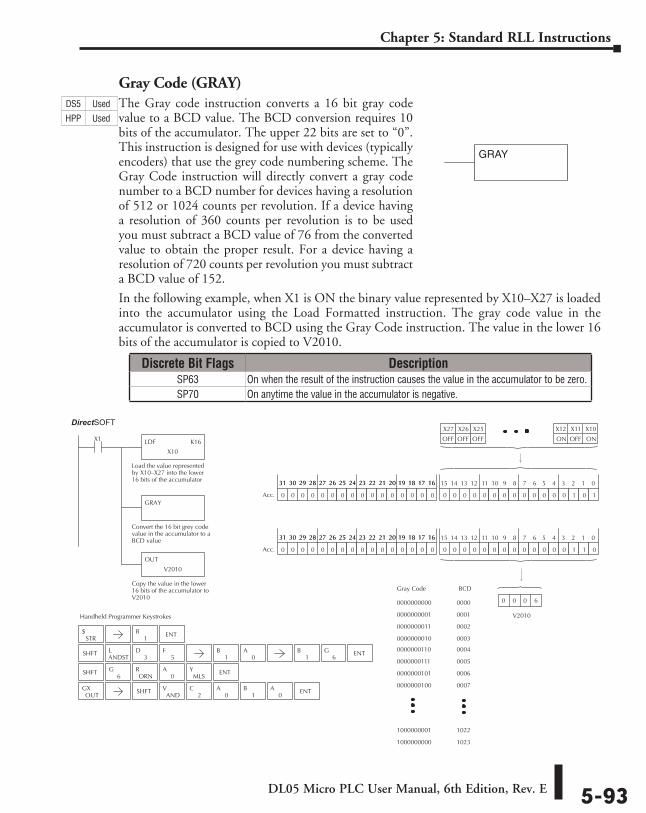
DL05 Micro PLC User Manual, 6th Edition, Rev. E 5-93
Chapter 5: Standard RLL Instructions
Gray Code (GRAY)The Gray code instruction converts a 16 bit gray code value to a BCD value. The BCD conversion requires 10 bits of the accumulator. The upper 22 bits are set to “0”. This instruction is designed for use with devices (typically encoders) that use the grey code numbering scheme. The Gray Code instruction will directly convert a gray code number to a BCD number for devices having a resolution of 512 or 1024 counts per revolution. If a device having a resolution of 360 counts per revolution is to be used you must subtract a BCD value of 76 from the converted value to obtain the proper result. For a device having a resolution of 720 counts per revolution you must subtract a BCD value of 152.
In the following example, when X1 is ON the binary value represented by X10–X27 is loaded into the accumulator using the Load Formatted instruction. The gray code value in the accumulator is converted to BCD using the Gray Code instruction. The value in the lower 16 bits of the accumulator is copied to V2010.
GRAY
Handheld Programmer Keystrokes
Direct SOFT32
LDF K16
X10
X1
Load the value representedby X10–X27 into the lower16 bits of the accumulator
GRAY
Convert the 16 bit grey codevalue in the accumulator to aBCD value
OUT
V2010
Copy the value in the lower16 bits of the accumulator toV2010
0000000000
Gray Code BCD
0000000001
0000000011
0000000010
0000000110
0000000111
0000000101
0000000100
1000000001
1000000000
0000
0001
0002
0003
0004
0005
0006
0007
1022
1023
X10X11X12
ONOFFON
0 0 0 0 0 0 0 0 0 0 0 0 0 1 0 10 0 0 0 0 0 0 0 0 0 0 0 0 0 0 0
15 14 13 12 11 10 9 8 7 6 5 4 3 2 1 031 30 29 28 27 26 25 24 23 22 21 20 19 18 17 1631 30 29 28 27 26 25 24 23 22 21 20 19 18 17 16
Acc.
0 0 0 0 0 0 0 0 0 0 0 0 0 1 1 00 0 0 0 0 0 0 0 0 0 0 0 0 0 0 0
15 14 13 12 11 10 9 8 7 6 5 4 3 2 1 031 30 29 28 27 26 25 24 23 22 21 20 19 18 17 1631 30 29 28 27 26 25 24 23 22 21 20 19 18 17 16
Acc.
X25X26X27
OFFOFFOFF
V2010
0 0 0 6
STR$
SHFTANDSTL
3D
5F
SHFT6
GORN
R0
AMLS
Y ENT
OUTGX SHFT
ANDV
2C
0A
1B
0A ENT
ENT1
B
1B
0A ENT
1B
6G
Discrete Bit Flags DescriptionSP63 On when the result of the instruction causes the value in the accumulator to be zero.SP70 On anytime the value in the accumulator is negative.
DS5 Used
HPP Used
DirectSOFT
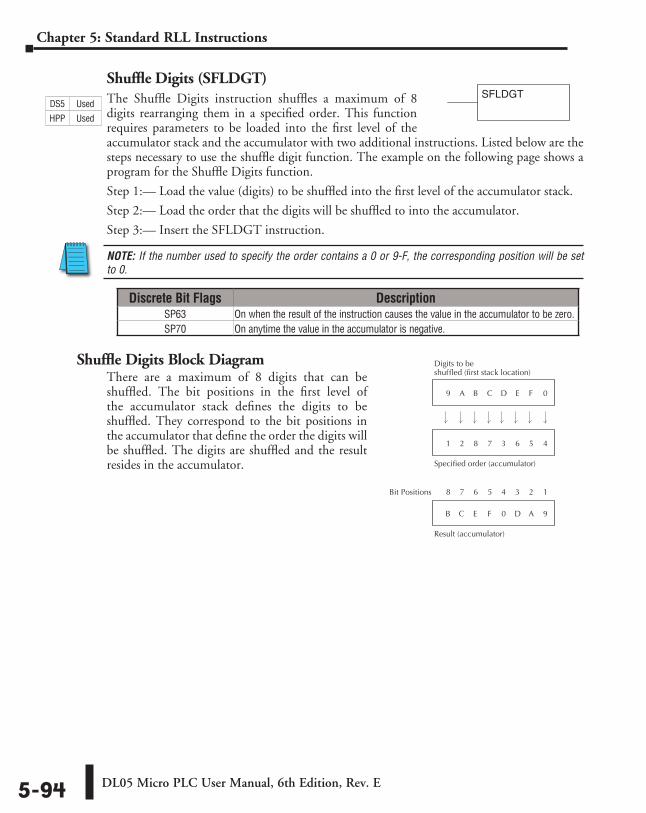
DL05 Micro PLC User Manual, 6th Edition, Rev. E5-94
Chapter 5: Standard RLL Instructions
Shuffle Digits (SFLDGT)The Shuffle Digits instruction shuffles a maximum of 8 digits rearranging them in a specified order. This function requires parameters to be loaded into the first level of the accumulator stack and the accumulator with two additional instructions. Listed below are the steps necessary to use the shuffle digit function. The example on the following page shows a program for the Shuffle Digits function.
Step 1:— Load the value (digits) to be shuffled into the first level of the accumulator stack.
Step 2:— Load the order that the digits will be shuffled to into the accumulator.
Step 3:— Insert the SFLDGT instruction.
NOTE: If the number used to specify the order contains a 0 or 9-F, the corresponding position will be set to 0.
Shuffle Digits Block DiagramThere are a maximum of 8 digits that can be shuffled. The bit positions in the first level of the accumulator stack defines the digits to be shuffled. They correspond to the bit positions in the accumulator that define the order the digits will be shuffled. The digits are shuffled and the result resides in the accumulator.
Digits to beshuffled (first stack location)
Specified order (accumulator)
D E F 09 A B C
3 6 5 41 2 8 7
Result (accumulator)
0 D A 9B C E F
4 3 2 18 7 6 5Bit Positions
Discrete Bit Flags DescriptionSP63 On when the result of the instruction causes the value in the accumulator to be zero.SP70 On anytime the value in the accumulator is negative.
SFLDGTDS5 Used
HPP Used
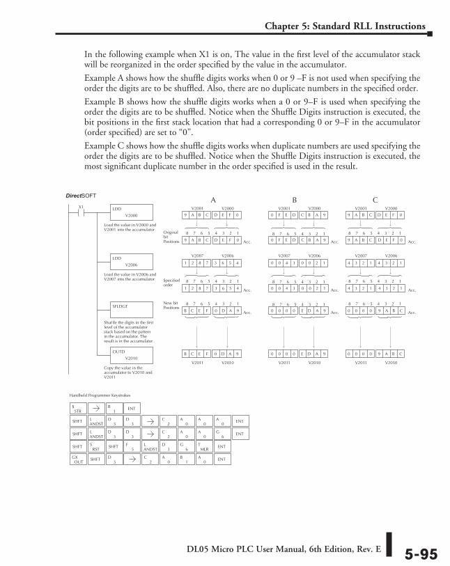
DL05 Micro PLC User Manual, 6th Edition, Rev. E 5-95
Chapter 5: Standard RLL Instructions
In the following example when X1 is on, The value in the first level of the accumulator stack will be reorganized in the order specified by the value in the accumulator.
Example A shows how the shuffle digits works when 0 or 9 –F is not used when specifying the order the digits are to be shuffled. Also, there are no duplicate numbers in the specified order.
Example B shows how the shuffle digits works when a 0 or 9–F is used when specifying the order the digits are to be shuffled. Notice when the Shuffle Digits instruction is executed, the bit positions in the first stack location that had a corresponding 0 or 9–F in the accumulator (order specified) are set to “0”.
Example C shows how the shuffle digits works when duplicate numbers are used specifying the order the digits are to be shuffled. Notice when the Shuffle Digits instruction is executed, the most significant duplicate number in the order specified is used in the result.
D E F 09 A B C
Handheld Programmer Keystrokes
Direct SOFT32
LDD
V2000
X1
Load the value in V2000 andV2001 into the accumulator
LDD
V2006
Load the value in V2006 andV2007 into the accumulator
OUTD
V2010
Copy the value in theaccumulator to V2010 andV2011
SFLDGT
Shuf fle the digits in the firstlevel of the accumulatorstack based on the patternin the accumulator. Theresult is in the accumulator .
V2010
Acc.
0 D A 9
9 A B C D E F 0
V2011
B C E F
Acc.
3 6 5 4
1 2 8 7 3 6 5 4
1 2 8 7
Acc.B C E F 0 D A 9
V2000V2001
V2006V2007
C B A 90 F E D
V2010
Acc.
E D A 9
0 F E D C B A 9
V2011
0 0 0 0
Acc.
0 0 2 1
0 0 4 3 0 0 2 1
0 0 4 3
Acc.0 0 0 0 E D A 9
V2000V2001
V2006V2007
D E F 09 A B C
V2010
Acc.
9 A B C
9 A B C D E F 0
V2011
0 0 0 0
Acc.
4 3 2 1
4 3 2 1 4 3 2 1
4 3 2 1
Acc.0 0 0 0 9 A B C
V2000V2001
V2006V2007
A B C
Original bitPositions
4 3 2 18 7 6 5 4 3 2 18 7 6 5 4 3 2 18 7 6 5
Specifiedorder
4 3 2 18 7 6 5 4 3 2 18 7 6 5 4 3 2 18 7 6 5
New bitPositions
4 3 2 18 7 6 5 4 3 2 18 7 6 5 4 3 2 18 7 6 5
STR$
SHFTANDSTL
3D
3D
SHFTANDSTL
3D
3D
SHFTRST
S5
FANDSTL
3D
6G
MLRT ENT
OUTGX SHFT
3D
1B ENT
2C
0A
0A
0A ENT
2C
0A
0A ENT
6G
2C
0A
1B
0A ENT
SHFT
DirectSOFT
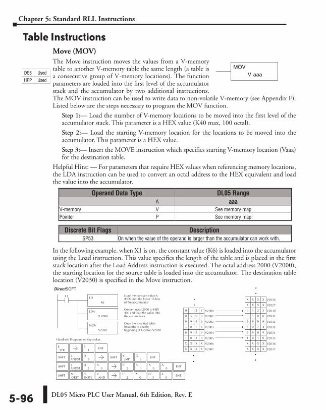
DL05 Micro PLC User Manual, 6th Edition, Rev. E5-96
Chapter 5: Standard RLL Instructions
Table InstructionsMove (MOV)The Move instruction moves the values from a V-memory table to another V-memory table the same length (a table is a consecutive group of V-memory locations). The function parameters are loaded into the first level of the accumulator stack and the accumulator by two additional instructions. The MOV instruction can be used to write data to non-volatile V-memory (see Appendix F). Listed below are the steps necessary to program the MOV function.
Step 1:— Load the number of V-memory locations to be moved into the first level of the accumulator stack. This parameter is a HEX value (K40 max, 100 octal).
Step 2:— Load the starting V-memory location for the locations to be moved into the accumulator. This parameter is a HEX value.
Step 3:— Insert the MOVE instruction which specifies starting V-memory location (Vaaa) for the destination table.
Helpful Hint: — For parameters that require HEX values when referencing memory locations, the LDA instruction can be used to convert an octal address to the HEX equivalent and load the value into the accumulator.
In the following example, when X1 is on, the constant value (K6) is loaded into the accumulator using the Load instruction. This value specifies the length of the table and is placed in the first stack location after the Load Address instruction is executed. The octal address 2000 (V2000), the starting location for the source table is loaded into the accumulator. The destination table location (V2030) is specified in the Move instruction.
V aaaMOV
Direct SOFT32
LD
K6
X1 Load the constant value 6(HEX) into the lower 16 bitsof the accumulator
LDA
O 2000
Convert octal 2000 to HEX400 and load the value intothe accumulator
MOV
V2030
Copy the specified tablelocations to a tablebeginning at location V2030
V20300 1 2 3
V20310 5 0 0
V20329 9 9 9
V20333 0 7 4
V20348 9 8 9
V20351 0 1 0
V2036X X X X
V2037X X X X
V2026X X X X
V2027X X X X
V20000 1 2 3
V20010 5 0 0
V20029 9 9 9
V20033 0 7 4
V20048 9 8 9
V20051 0 1 0
V2006X X X X
V2007X X X X
Handheld Programmer Keystrokes
STR$
SHFTANDSTL
3D SHFT
JMPK
6G ENT
SHFTANDSTL
3D
0A
2C
0A
0A
0A ENT
SHFTORSTM
INST#O
1B ENT
2C
0A
0A ENT
3D
ANDV
Discrete Bit Flags DescriptionSP53 On when the value of the operand is larger than the accumulator can work with.
Operand Data Type DL05 Range ⸠⸠⸠⸠⸠⸠⸠⸠⸠⸠⸠⸠⸠⸠⸠⸠⸠⸠⸠⸠⸠⸠⸠⸠⸠⸠⸠⸠⸠⸠⸠⸠⸠⸠⸠⸠⸠⸠⸠⸠⸠⸠⸠⸠⸠⸠⸠⸠⸠⸠⸠⸠⸠⸠⸠⸠⸠⸠⸠⸠⸠⸠⸠⸠⸠⸠⸠⸠⸠⸠⸠⸠⸠A aaaV-memory ⸠⸠⸠⸠⸠⸠⸠⸠⸠⸠⸠⸠⸠⸠⸠⸠⸠⸠⸠⸠⸠⸠⸠⸠⸠⸠⸠⸠⸠⸠⸠⸠⸠⸠⸠⸠⸠⸠⸠⸠⸠⸠⸠⸠⸠⸠⸠⸠⸠⸠⸠⸠⸠⸠⸠⸠⸠⸠V See memory mapPointer ⸠⸠⸠⸠⸠⸠⸠⸠⸠⸠⸠⸠⸠⸠⸠⸠⸠⸠⸠⸠⸠⸠⸠⸠⸠⸠⸠⸠⸠⸠⸠⸠⸠⸠⸠⸠⸠⸠⸠⸠⸠⸠⸠⸠⸠⸠⸠⸠⸠⸠⸠⸠⸠⸠⸠⸠⸠⸠⸠⸠⸠⸠⸠⸠P See memory map
DS5 Used
HPP Used
DirectSOFT
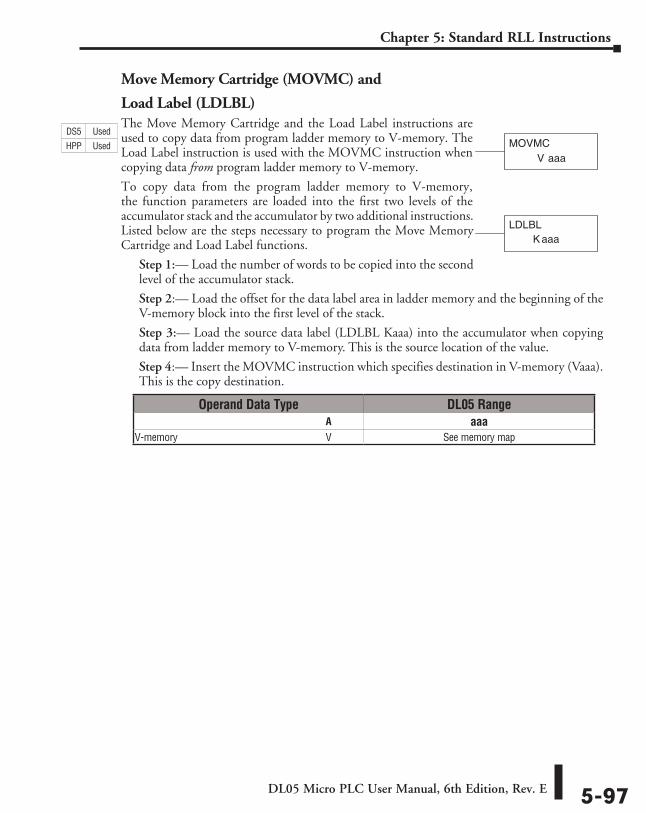
DL05 Micro PLC User Manual, 6th Edition, Rev. E 5-97
Chapter 5: Standard RLL Instructions
Move Memory Cartridge (MOVMC) and
Load Label (LDLBL)The Move Memory Cartridge and the Load Label instructions are used to copy data from program ladder memory to V-memory. The Load Label instruction is used with the MOVMC instruction when copying data from program ladder memory to V-memory.
To copy data from the program ladder memory to V-memory, the function parameters are loaded into the first two levels of the accumulator stack and the accumulator by two additional instructions. Listed below are the steps necessary to program the Move Memory Cartridge and Load Label functions.
Step 1:— Load the number of words to be copied into the second level of the accumulator stack.
Step 2:— Load the offset for the data label area in ladder memory and the beginning of the V-memory block into the first level of the stack.
Step 3:— Load the source data label (LDLBL Kaaa) into the accumulator when copying data from ladder memory to V-memory. This is the source location of the value.
Step 4:— Insert the MOVMC instruction which specifies destination in V-memory (Vaaa). This is the copy destination.
V aaaMOVMC
LDLBLaaaK
Operand Data Type DL05 Range ⸠⸠⸠⸠⸠⸠⸠⸠⸠⸠⸠⸠⸠⸠⸠⸠⸠⸠⸠⸠⸠⸠⸠⸠⸠⸠⸠⸠⸠⸠⸠⸠⸠⸠⸠⸠⸠⸠⸠⸠⸠⸠⸠⸠⸠⸠⸠⸠⸠⸠⸠⸠⸠⸠⸠⸠⸠⸠⸠⸠⸠⸠⸠⸠⸠⸠⸠⸠⸠⸠⸠⸠⸠A aaaV-memory ⸠⸠⸠⸠⸠⸠⸠⸠⸠⸠⸠⸠⸠⸠⸠⸠⸠⸠⸠⸠⸠⸠⸠⸠⸠⸠⸠⸠⸠⸠⸠⸠⸠⸠⸠⸠⸠⸠⸠⸠⸠⸠⸠⸠⸠⸠⸠⸠⸠⸠⸠⸠⸠⸠⸠⸠⸠⸠V See memory map
DS5 Used
HPP Used
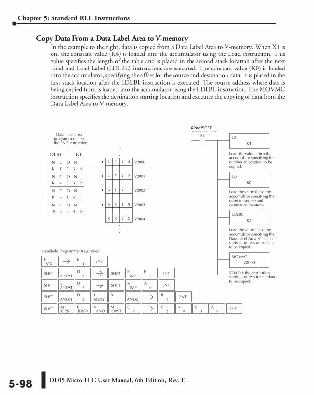
DL05 Micro PLC User Manual, 6th Edition, Rev. E5-98
Chapter 5: Standard RLL Instructions
Copy Data From a Data Label Area to V-memoryIn the example to the right, data is copied from a Data Label Area to V-memory. When X1 is on, the constant value (K4) is loaded into the accumulator using the Load instruction. This value specifies the length of the table and is placed in the second stack location after the next Load and Load Label (LDLBL) instructions are executed. The constant value (K0) is loaded into the accumulator, specifying the offset for the source and destination data. It is placed in the first stack location after the LDLBL instruction is executed. The source address where data is being copied from is loaded into the accumulator using the LDLBL instruction. The MOVMC instruction specifies the destination starting location and executes the copying of data from the Data Label Area to V-memory.
Direct SOFT32
LD
K4
X1
Load the value 4 into theaccumulator specifying thenumber of locations to becopied.
LD
K0
Load the value 0 into theaccumulator specifying theoffset for source anddestination locations
LDLBL
K1
Load the value 1 into theaccumulator specifying theData Label Area K1 as thestarting address of the datato be copied.
MOVMC
V2000
V2000 is the destinationstarting address for the datato be copied.
1 2 3 4
4 5 3 2
6 1 5 1
8 8 4 5
K
N C O N
K
N C O N
K
N C O N
K
N C O N
V20014 5 3 2
V20026 1 5 1
V20038 8 4 5
V2004X X X X
.
.
.
.V20001 2 3 4
Data label areaprogrammed after
the END instruction
DLBL
Handheld Programmer Keystrokes
STR$
SHFTANDSTL
3D SHFT
JMPK ENT
SHFTANDSTL
3D
ANDSTL
1B
ANDSTL
SHFTORSTM
ANDV
INST#O
ORSTM
2C
1B ENT
ENT1
B
2C
0A
0A
0A ENT
SHFTANDSTL
3D SHFT
JMPK
0A ENT
4E
K1
DirectSOFT
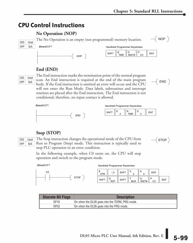
DL05 Micro PLC User Manual, 6th Edition, Rev. E 5-99
Chapter 5: Standard RLL Instructions
CPU Control InstructionsNo Operation (NOP)The No Operation is an empty (not programmed) memory location.
End (END)The End instruction marks the termination point of the normal program scan. An End instruction is required at the end of the main program body. If the End instruction is omitted an error will occur and the CPU will not enter the Run Mode. Data labels, subroutines and interrupt routines are placed after the End instruction. The End instruction is not conditional; therefore, no input contact is allowed.
Stop (STOP)The Stop instruction changes the operational mode of the CPU from Run to Program (Stop) mode. This instruction is typically used to stop PLC operation in an error condition.
In the following example, when C0 turns on, the CPU will stop operation and switch to the program mode.
NOP
END
DirectSOFT32 Handheld Programmer Keystrokes
ENDSHFT 4
ETMR
N3
D ENT
STOP
DirectSOFT32 Handheld Programmer Keystrokes
STOP
C0STR
$ SHFT ENT2C
0A
SHFT RSTS
MLRT
INST#O
CVP ENTSHFT
Discrete Bit Flags DescriptionSP16 On when the DL05 goes into the TERM_PRG mode.SP53 On when the DL05 goes into the PRG mode.
DirectSOFT32 Handheld Programmer Keystrokes
NOPSHFT TMR
NINST#O
CVP ENT
DS5 Used
HPP N/A
DS5 Used
HPP N/A
DS5 Used
HPP N/A DirectSOFT
DirectSOFT
DirectSOFT
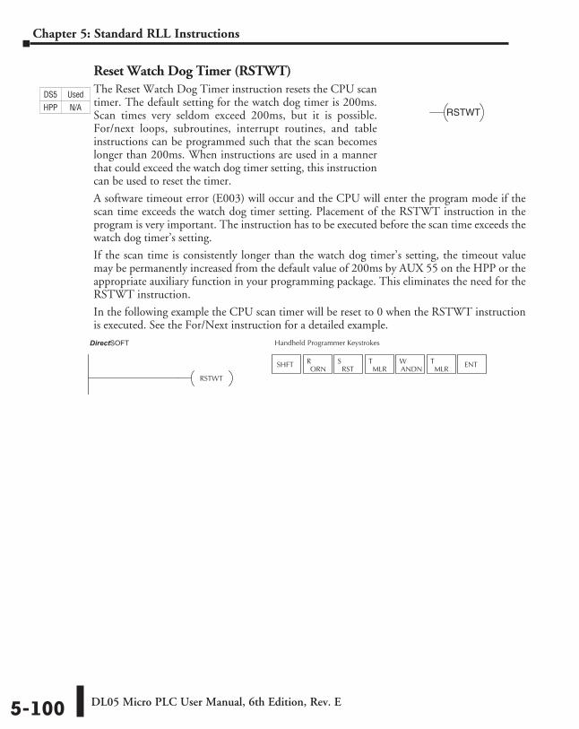
DL05 Micro PLC User Manual, 6th Edition, Rev. E5-100
Chapter 5: Standard RLL Instructions
Reset Watch Dog Timer (RSTWT)The Reset Watch Dog Timer instruction resets the CPU scan timer. The default setting for the watch dog timer is 200ms. Scan times very seldom exceed 200ms, but it is possible. For/next loops, subroutines, interrupt routines, and table instructions can be programmed such that the scan becomes longer than 200ms. When instructions are used in a manner that could exceed the watch dog timer setting, this instruction can be used to reset the timer.
A software timeout error (E003) will occur and the CPU will enter the program mode if the scan time exceeds the watch dog timer setting. Placement of the RSTWT instruction in the program is very important. The instruction has to be executed before the scan time exceeds the watch dog timer’s setting.
If the scan time is consistently longer than the watch dog timer’s setting, the timeout value may be permanently increased from the default value of 200ms by AUX 55 on the HPP or the appropriate auxiliary function in your programming package. This eliminates the need for the RSTWT instruction.
In the following example the CPU scan timer will be reset to 0 when the RSTWT instruction is executed. See the For/Next instruction for a detailed example.
RSTWT
Direct SOFT 32 Handheld Programmer Keystrokes
RSTWT
SHFTORN
RRST
SMLR
TANDNW
MLRT ENT
DS5 Used
HPP N/A
DirectSOFT
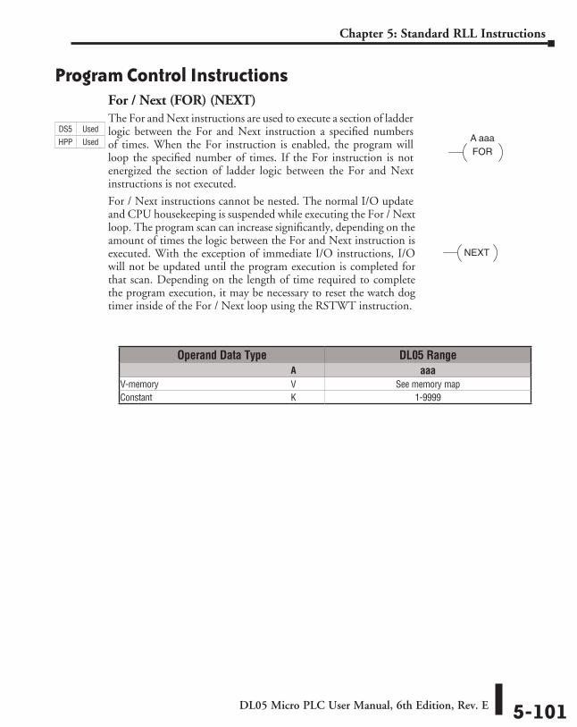
DL05 Micro PLC User Manual, 6th Edition, Rev. E 5-101
Chapter 5: Standard RLL Instructions
Program Control InstructionsFor / Next (FOR) (NEXT)The For and Next instructions are used to execute a section of ladder logic between the For and Next instruction a specified numbers of times. When the For instruction is enabled, the program will loop the specified number of times. If the For instruction is not energized the section of ladder logic between the For and Next instructions is not executed.
For / Next instructions cannot be nested. The normal I/O update and CPU housekeeping is suspended while executing the For / Next loop. The program scan can increase significantly, depending on the amount of times the logic between the For and Next instruction is executed. With the exception of immediate I/O instructions, I/O will not be updated until the program execution is completed for that scan. Depending on the length of time required to complete the program execution, it may be necessary to reset the watch dog timer inside of the For / Next loop using the RSTWT instruction.
A aaaFOR
NEXT
Operand Data Type DL05 Range ⸠⸠⸠⸠⸠⸠⸠⸠⸠⸠⸠⸠⸠⸠⸠⸠⸠⸠⸠⸠⸠⸠⸠⸠⸠⸠⸠⸠⸠⸠⸠⸠⸠⸠⸠⸠⸠⸠⸠⸠⸠⸠⸠⸠⸠⸠⸠⸠⸠⸠⸠⸠⸠⸠⸠⸠⸠⸠⸠⸠⸠⸠⸠⸠⸠⸠⸠⸠⸠⸠⸠⸠⸠A aaaV-memory ⸠⸠⸠⸠⸠⸠⸠⸠⸠⸠⸠⸠⸠⸠⸠⸠⸠⸠⸠⸠⸠⸠⸠⸠⸠⸠⸠⸠⸠⸠⸠⸠⸠⸠⸠⸠⸠⸠⸠⸠⸠⸠⸠⸠⸠⸠⸠⸠⸠⸠⸠⸠⸠⸠⸠⸠⸠⸠V See memory mapConstant ⸠⸠⸠⸠⸠⸠⸠⸠⸠⸠⸠⸠⸠⸠⸠⸠⸠⸠⸠⸠⸠⸠⸠⸠⸠⸠⸠⸠⸠⸠⸠⸠⸠⸠⸠⸠⸠⸠⸠⸠⸠⸠⸠⸠⸠⸠⸠⸠⸠⸠⸠⸠⸠⸠⸠⸠⸠⸠⸠⸠⸠K 1-9999
DS5 Used
HPP Used
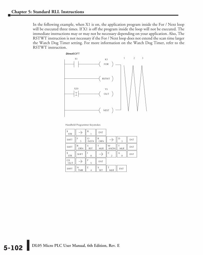
DL05 Micro PLC User Manual, 6th Edition, Rev. E5-102
Chapter 5: Standard RLL Instructions
In the following example, when X1 is on, the application program inside the For / Next loop will be executed three times. If X1 is off the program inside the loop will not be executed. The immediate instructions may or may not be necessary depending on your application. Also, The RSTWT instruction is not necessary if the For / Next loop does not extend the scan time larger the Watch Dog Timer setting. For more information on the Watch Dog Timer, refer to the RSTWT instruction.
X1Direct SOFT32
Handheld Programmer Keystrokes
K3
FOR
RSTWT
X20 Y5
OUT
NEXT
1 2 3
STR$
SHFT5
FINST#O
ORNR
SHFTORN
RRST
SMLR
TANDNW
MLRT ENT
STR$ SHFT
8I
2C
0A ENT
OUTGX
SHFTTMR
N4
ESET
XMLR
T ENT
1B ENT
3D ENT
5F ENT
DirectSOFT
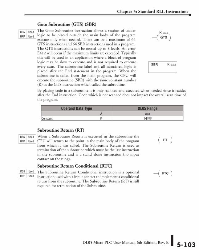
DL05 Micro PLC User Manual, 6th Edition, Rev. E 5-103
Chapter 5: Standard RLL Instructions
Goto Subroutine (GTS) (SBR)The Goto Subroutine instruction allows a section of ladder logic to be placed outside the main body of the program execute only when needed. There can be a maximum of 64 GTS instructions and 64 SBR instructions used in a program. The GTS instructions can be nested up to 8 levels. An error E412 will occur if the maximum limits are exceeded. Typically this will be used in an application where a block of program logic may be slow to execute and is not required to execute every scan. The subroutine label and all associated logic is placed after the End statement in the program. When the subroutine is called from the main program, the CPU will execute the subroutine (SBR) with the same constant number (K) as the GTS instruction which called the subroutine.
By placing code in a subroutine it is only scanned and executed when needed since it resides after the End instruction. Code which is not scanned does not impact the overall scan time of the program.
Subroutine Return (RT)When a Subroutine Return is executed in the subroutine the CPU will return to the point in the main body of the program from which it was called. The Subroutine Return is used as termination of the subroutine which must be the last instruction in the subroutine and is a stand alone instruction (no input contact on the rung).
Subroutine Return Conditional (RTC)The Subroutine Return Conditional instruction is a optional instruction used with a input contact to implement a conditional return from the subroutine. The Subroutine Return (RT) is still required for termination of the Subroutine.
K aaa
GTS
K aaaSBR
RT
RTC
Operand Data Type DL05 Range ⸠⸠⸠⸠⸠⸠⸠⸠⸠⸠⸠⸠⸠⸠⸠⸠⸠⸠⸠⸠⸠⸠⸠⸠⸠⸠⸠⸠⸠⸠⸠⸠⸠⸠⸠⸠⸠⸠⸠⸠⸠⸠⸠⸠⸠⸠⸠⸠⸠⸠⸠⸠⸠⸠⸠⸠⸠⸠⸠⸠⸠⸠⸠⸠⸠⸠⸠⸠⸠⸠⸠⸠⸠A aaaConstant ⸠⸠⸠⸠⸠⸠⸠⸠⸠⸠⸠⸠⸠⸠⸠⸠⸠⸠⸠⸠⸠⸠⸠⸠⸠⸠⸠⸠⸠⸠⸠⸠⸠⸠⸠⸠⸠⸠⸠⸠⸠⸠⸠⸠⸠⸠⸠⸠⸠⸠⸠⸠⸠⸠⸠⸠⸠⸠⸠⸠⸠K 1-FFFF
DS5 Used
HPP Used
DS5 Used
HPP Used
DS5 Used
HPP Used
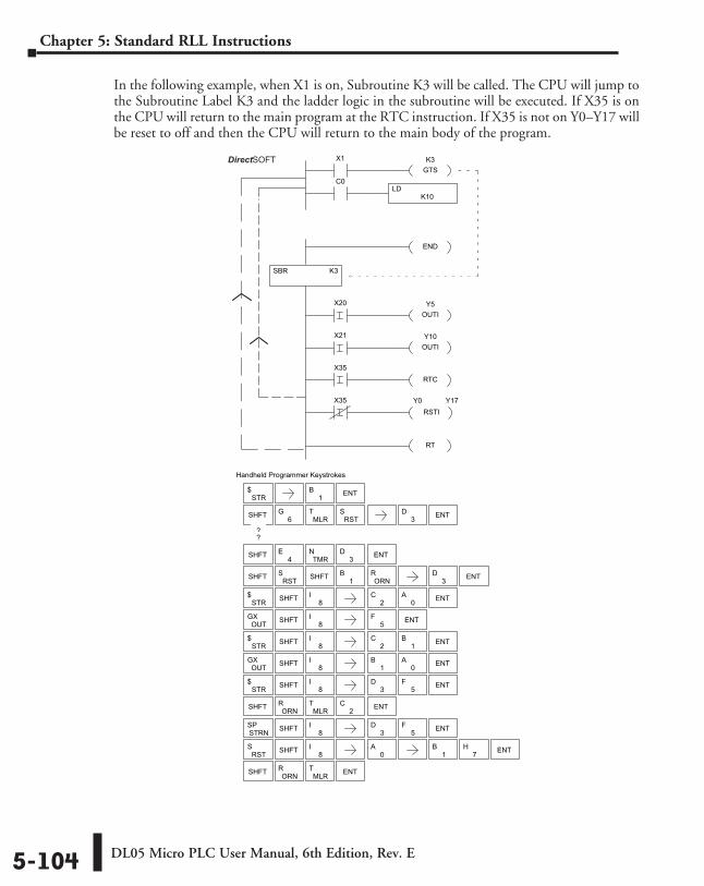
DL05 Micro PLC User Manual, 6th Edition, Rev. E5-104
Chapter 5: Standard RLL Instructions
In the following example, when X1 is on, Subroutine K3 will be called. The CPU will jump to the Subroutine Label K3 and the ladder logic in the subroutine will be executed. If X35 is on the CPU will return to the main program at the RTC instruction. If X35 is not on Y0–Y17 will be reset to off and then the CPU will return to the main body of the program.
Direct SOFT32 Display
Handheld Programmer Keystrokes
SBR K3
X1 K3GTS
END
Y5OUTI
X20
Y10OUTI
X21
X35
RTCX35
RSTIY0 Y17
RT
K10LD
C0
STR$
SHFT 6G
MLRT
RSTS
SHFT RSTS
1B
ORNR
STR$ SHFT 8
I2
C0
A ENT
OUTGX
STR$
SHFT 8I
3D ENT5
F
OUTGX
SHFT ORNR
MLRT ENT
SHFT 4E
TMRN
3D ENT
1B ENT
3D ENT
3D ENT
5F ENT
ENT1B
0A
SHFT
??
SHFT 8I
SHFT 8I
2C
STR$ SHFT 8
I2
C ENT1B
STRNSP
RSTS SHFT 8
I0
A1
B7
H ENT
SHFT 8I
3D ENT5
F
SHFT ORNR
MLRT ENT
DirectSOFT
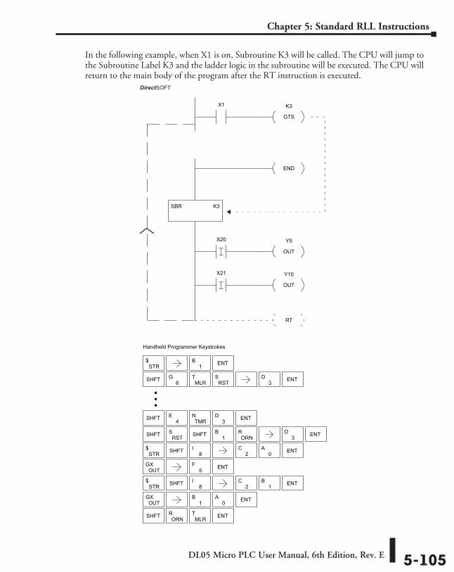
DL05 Micro PLC User Manual, 6th Edition, Rev. E 5-105
Chapter 5: Standard RLL Instructions
In the following example, when X1 is on, Subroutine K3 will be called. The CPU will jump to the Subroutine Label K3 and the ladder logic in the subroutine will be executed. The CPU will return to the main body of the program after the RT instruction is executed.
Direct SOFT
Handheld Programmer Keystrokes
SBR K3
X1 K3
GTS
END
Y5
OUT
X20
Y10
OUT
X21
RT
STR$
SHFT 6G
MLRT
RSTS
SHFT RSTS
1B
ORNR
STR$ SHFT 8
I2
C0
A ENT
OUTGX
STR$ SHFT 8
I2
C ENT1B
OUTGX
SHFT ORNR
MLRT ENT
SHFT 4E
TMRN
3D ENT
1B ENT
3D ENT
3D ENT
5F ENT
ENT1B
0A
SHFT
32
�
�
�
DirectSOFT
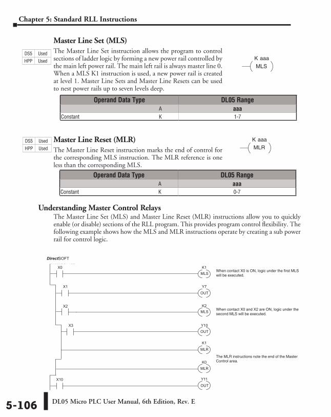
DL05 Micro PLC User Manual, 6th Edition, Rev. E5-106
Chapter 5: Standard RLL Instructions
Master Line Set (MLS)The Master Line Set instruction allows the program to control sections of ladder logic by forming a new power rail controlled by the main left power rail. The main left rail is always master line 0. When a MLS K1 instruction is used, a new power rail is created at level 1. Master Line Sets and Master Line Resets can be used to nest power rails up to seven levels deep.
Master Line Reset (MLR)The Master Line Reset instruction marks the end of control for the corresponding MLS instruction. The MLR reference is one less than the corresponding MLS.
Understanding Master Control RelaysThe Master Line Set (MLS) and Master Line Reset (MLR) instructions allow you to quickly enable (or disable) sections of the RLL program. This provides program control flexibility. The following example shows how the MLS and MLR instructions operate by creating a sub power rail for control logic.
K aaa
MLS
K aaa
MLR
X0
X1
X2
OUT
Y7
X3
MLS
X10
K1
K2
K0
K1
MLS
OUT
MLR
MLR
OUT
Y10
Y11
Direct SOFT32
When contact X0 is ON, logic under the first MLSwill be executed.
When contact X0 and X2 are ON, logic under the second MLS will be executed.
The MLR instructions note the end of the MasterControl area.
Operand Data Type DL05 Range ⸠⸠⸠⸠⸠⸠⸠⸠⸠⸠⸠⸠⸠⸠⸠⸠⸠⸠⸠⸠⸠⸠⸠⸠⸠⸠⸠⸠⸠⸠⸠⸠⸠⸠⸠⸠⸠⸠⸠⸠⸠⸠⸠⸠⸠⸠⸠⸠⸠⸠⸠⸠⸠⸠⸠⸠⸠⸠⸠⸠⸠⸠⸠⸠⸠⸠⸠⸠⸠⸠⸠⸠⸠A aaaConstant ⸠⸠⸠⸠⸠⸠⸠⸠⸠⸠⸠⸠⸠⸠⸠⸠⸠⸠⸠⸠⸠⸠⸠⸠⸠⸠⸠⸠⸠⸠⸠⸠⸠⸠⸠⸠⸠⸠⸠⸠⸠⸠⸠⸠⸠⸠⸠⸠⸠⸠⸠⸠⸠⸠⸠⸠⸠⸠⸠⸠⸠K 0-7
Operand Data Type DL05 Range ⸠⸠⸠⸠⸠⸠⸠⸠⸠⸠⸠⸠⸠⸠⸠⸠⸠⸠⸠⸠⸠⸠⸠⸠⸠⸠⸠⸠⸠⸠⸠⸠⸠⸠⸠⸠⸠⸠⸠⸠⸠⸠⸠⸠⸠⸠⸠⸠⸠⸠⸠⸠⸠⸠⸠⸠⸠⸠⸠⸠⸠⸠⸠⸠⸠⸠⸠⸠⸠⸠⸠⸠⸠A aaaConstant ⸠⸠⸠⸠⸠⸠⸠⸠⸠⸠⸠⸠⸠⸠⸠⸠⸠⸠⸠⸠⸠⸠⸠⸠⸠⸠⸠⸠⸠⸠⸠⸠⸠⸠⸠⸠⸠⸠⸠⸠⸠⸠⸠⸠⸠⸠⸠⸠⸠⸠⸠⸠⸠⸠⸠⸠⸠⸠⸠⸠⸠K 1-7
DS5 Used
HPP Used
DS5 Used
HPP Used
DirectSOFT
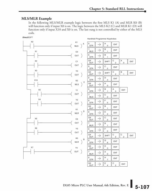
DL05 Micro PLC User Manual, 6th Edition, Rev. E 5-107
Chapter 5: Standard RLL Instructions
MLS/MLR ExampleIn the following MLS/MLR example logic between the first MLS K1 (A) and MLR K0 (B) will function only if input X0 is on. The logic between the MLS K2 (C) and MLR K1 (D) will function only if input X10 and X0 is on. The last rung is not controlled by either of the MLS coils.
K1
MLS
X0
C0
OUT
X1
C1
OUT
X2
Y0
OUT
X3
K2
MLS
X10
Y1
OUT
X5
Y2
OUT
X4
K1
MLR
C2
OUT
X5
Y3
OUT
X6
K0
MLR
Y4
OUT
X7
DirectSOFT32 Handheld Programmer Keystrokes
STR$ ENT
0A
MLSY
1B ENT
STR$
1B ENT
OUTGX SHFT ENT
2C
0A
STR$ ENT
2C
OUTGX SHFT ENT
2C
1B
STR$ ENT
3D
OUTGX ENT
0A
STR$ ENT
0A
1B
MLSY ENT
2C
STR$ ENT
5F
OUTGX ENT
1B
STR$ ENT
OUTGX ENT
4E
2C
MLRT
1B ENT
STR$ ENT
5F
OUTGX SHFT ENT
2C
2C
STR$ ENT
OUTGX ENT
6G
3D
MLRT ENT
0A
STR$ ENT
OUTGX
4E
7H
ENT2
C
A
C
D
B
DirectSOFT
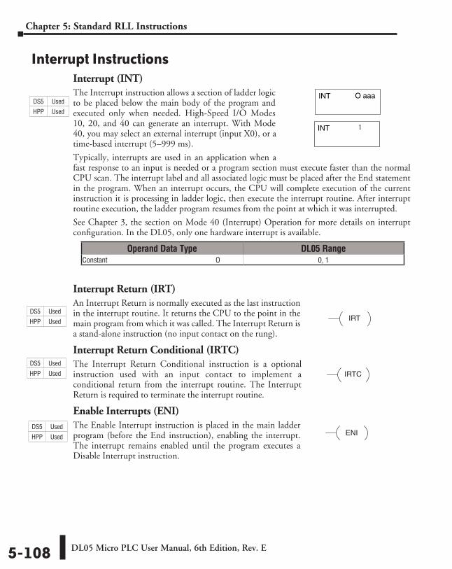
DL05 Micro PLC User Manual, 6th Edition, Rev. E5-108
Chapter 5: Standard RLL Instructions
Interrupt InstructionsInterrupt (INT)The Interrupt instruction allows a section of ladder logic to be placed below the main body of the program and executed only when needed. High-Speed I/O Modes 10, 20, and 40 can generate an interrupt. With Mode 40, you may select an external interrupt (input X0), or a time-based interrupt (5–999 ms).
Typically, interrupts are used in an application when a fast response to an input is needed or a program section must execute faster than the normal CPU scan. The interrupt label and all associated logic must be placed after the End statement in the program. When an interrupt occurs, the CPU will complete execution of the current instruction it is processing in ladder logic, then execute the interrupt routine. After interrupt routine execution, the ladder program resumes from the point at which it was interrupted.
See Chapter 3, the section on Mode 40 (Interrupt) Operation for more details on interrupt configuration. In the DL05, only one hardware interrupt is available.
Interrupt Return (IRT)An Interrupt Return is normally executed as the last instruction in the interrupt routine. It returns the CPU to the point in the main program from which it was called. The Interrupt Return is a stand-alone instruction (no input contact on the rung).
Interrupt Return Conditional (IRTC)The Interrupt Return Conditional instruction is a optional instruction used with an input contact to implement a conditional return from the interrupt routine. The Interrupt Return is required to terminate the interrupt routine.
Enable Interrupts (ENI)The Enable Interrupt instruction is placed in the main ladder program (before the End instruction), enabling the interrupt. The interrupt remains enabled until the program executes a Disable Interrupt instruction.
O aaaINT
INT
1
IRT
IRTC
ENI
Operand Data Type DL05 RangeConstant ⸠⸠⸠⸠⸠⸠⸠⸠⸠⸠⸠⸠⸠⸠⸠⸠⸠⸠⸠⸠⸠⸠⸠⸠⸠⸠⸠⸠⸠⸠⸠⸠⸠⸠⸠⸠⸠⸠⸠⸠⸠⸠⸠⸠⸠⸠⸠⸠⸠⸠⸠⸠⸠⸠⸠⸠⸠⸠⸠⸠⸠O 0, 1
DS5 Used
HPP Used
DS5 Used
HPP Used
DS5 Used
HPP Used
DS5 Used
HPP Used
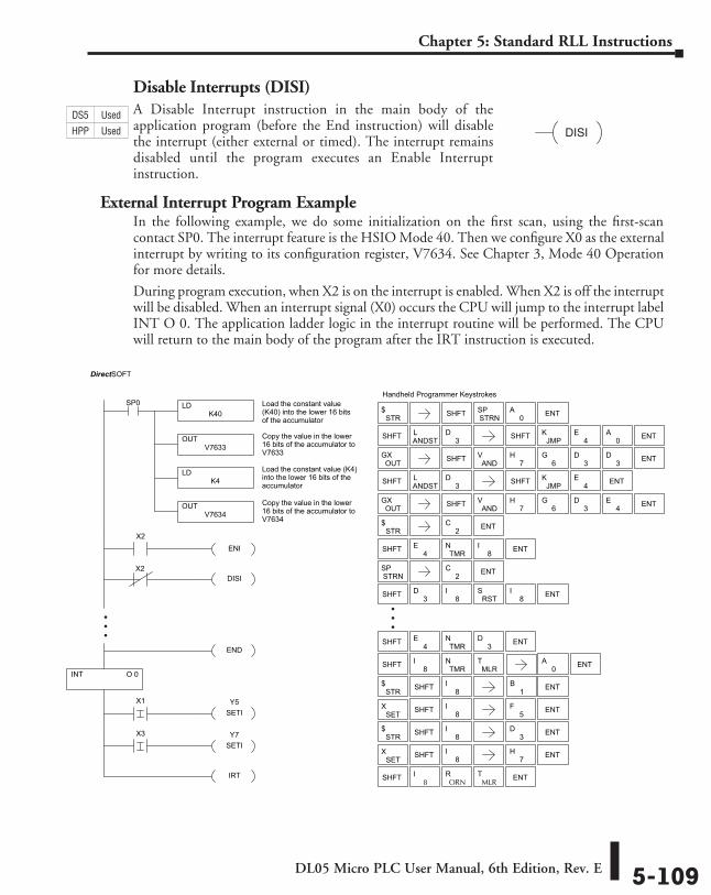
DL05 Micro PLC User Manual, 6th Edition, Rev. E 5-109
Chapter 5: Standard RLL Instructions
Disable Interrupts (DISI)A Disable Interrupt instruction in the main body of the application program (before the End instruction) will disable the interrupt (either external or timed). The interrupt remains disabled until the program executes an Enable Interrupt instruction.
External Interrupt Program ExampleIn the following example, we do some initialization on the first scan, using the first-scan contact SP0. The interrupt feature is the HSIO Mode 40. Then we configure X0 as the external interrupt by writing to its configuration register, V7634. See Chapter 3, Mode 40 Operation for more details.
During program execution, when X2 is on the interrupt is enabled. When X2 is off the interrupt will be disabled. When an interrupt signal (X0) occurs the CPU will jump to the interrupt label INT O 0. The application ladder logic in the interrupt routine will be performed. The CPU will return to the main body of the program after the IRT instruction is executed.
DISI
O 0
X2ENI
DISIX2
END
Y5SETI
X1
Y7SETI
X3
IRT
Handheld Programmer Keystrokes
8I
ORNR
MLRT
STR$ SHFT 8
I1
B ENT
SHFT 8I
5F ENT
STR$ SHFT 8
I3
D ENT
SHFT 8I ENT7
H
SHFT 4E
TMRN
3D ENT
STR$ ENT2
C
SHFT 4E
TMRN
8I ENT
STRNSP ENT2
C
SHFT 8I
TMRN
MLRT
0A ENT
SHFT ENT
SHFT ENT3D
8I
RSTS
8I
SETX
SETX
LDK40
SP0 Load the constant value(K40) into the lower 16 bitsof the accumulator
OUTV7633
Copy the value in the lower16 bits of the accumulator toV7633
LDK4
Load the constant value (K4)into the lower 16 bits of theaccumulator
OUTV7634
Copy the value in the lower16 bits of the accumulator toV7634
STR$
SHFT ANDSTL
3D SHFT
OUTGX SHFT AND
V ENT
JMPK ENT
7H
6G
3D
4E
SHFT ANDSTL
3D SHFT 0
A
OUTGX SHFT AND
V ENT
JMPK
4E ENT
7H
6G
3D
3D
4E
SHFT ENTSTRNSP
0A
INT
DirectSOFT
�
�
�
�
�
�
DS5 Used
HPP Used
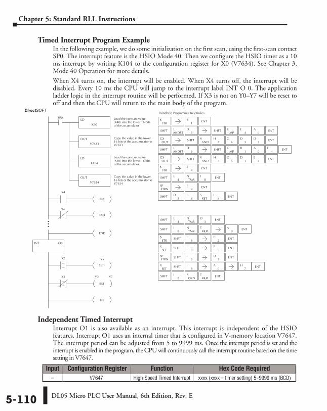
DL05 Micro PLC User Manual, 6th Edition, Rev. E5-110
Chapter 5: Standard RLL Instructions
Timed Interrupt Program ExampleIn the following example, we do some initialization on the first scan, using the first-scan contact SP0. The interrupt feature is the HSIO Mode 40. Then we configure the HSIO timer as a 10 ms interrupt by writing K104 to the configuration register for X0 (V7634). See Chapter 3, Mode 40 Operation for more details.
When X4 turns on, the interrupt will be enabled. When X4 turns off, the interrupt will be disabled. Every 10 ms the CPU will jump to the interrupt label INT O 0. The application ladder logic in the interrupt routine will be performed. If X3 is not on Y0–Y7 will be reset to off and then the CPU will return to the main body of the program.
Independent Timed InterruptInterrupt O1 is also available as an interrupt. This interrupt is independent of the HSIO features. Interrupt O1 uses an internal timer that is configured in V-memory location V7647. The interrupt period can be adjusted from 5 to 9999 ms. Once the interrupt period is set and the interrupt is enabled in the program, the CPU will continuously call the interrupt routine based on the time setting in V7647.
Direct SOFT32
INT O0
X4
ENI
DISI
X4
END
Y5
SETI
X2
X3
RSTI
Y0 Y7
IRT
Handheld Programmer Keystrokes
LD
K40
SP0 Load the constant value(K40) into the lower 16 bitsof the accumulator
OUT
V7633
Copy the value in the lower16 bits of the accumulator toV7633
STR$
SHFTANDSTL
3D SHFT
0A
OUTGX SHFT
ANDV ENT
JMPK
1B ENT
7H
6G
3D
4E
STR$
SHFT4
ETMR
N8
I ENT
STRNSP
SHFT ENT3
D8
IRST
S8
I
8I
ORNR
MLRT
STR$ SHFT
8I
2C ENT
SHFT8
I5
F ENT
SHFT8
I ENT
SHFT8
I ENT0
A
SHFT4
ETMR
N3
D ENT
SHFT8
ITMR
NMLR
T ENT
SHFT ENT
0A
1B ENT
ENT
ENT
4E
4E
7H
3D
SETX
SETX
STRNSP
LD
K104
Load the constant value(K10) into the lower 16 bitsof the accumulator
OUT
V7634
Copy the value in the lower16 bits of the accumulator toV7634
SHFTANDSTL
3D SHFT
0A
OUTGX SHFT
ANDV ENT
JMPK
4E ENT
7H
6G
3D
3D
4E
Input Configuration Register Function Hex Code Required– V7647 High-Speed Timed Interrupt xxxx (xxxx = timer setting) 5–9999 ms (BCD)
DirectSOFT
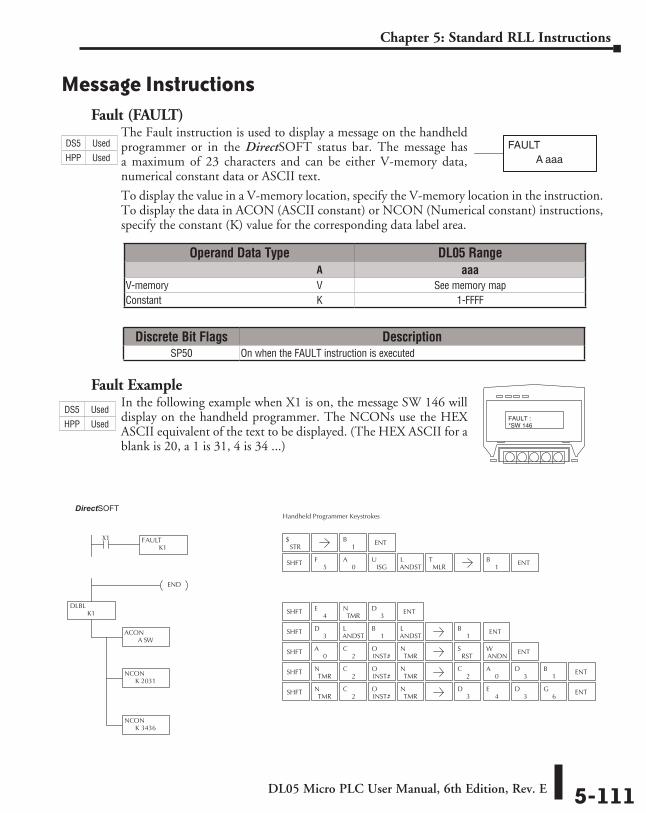
DL05 Micro PLC User Manual, 6th Edition, Rev. E 5-111
Chapter 5: Standard RLL Instructions
Message InstructionsFault (FAULT)
The Fault instruction is used to display a message on the handheld programmer or in the DirectSOFT status bar. The message has a maximum of 23 characters and can be either V-memory data, numerical constant data or ASCII text.
To display the value in a V-memory location, specify the V-memory location in the instruction. To display the data in ACON (ASCII constant) or NCON (Numerical constant) instructions, specify the constant (K) value for the corresponding data label area.
Fault ExampleIn the following example when X1 is on, the message SW 146 will display on the handheld programmer. The NCONs use the HEX ASCII equivalent of the text to be displayed. (The HEX ASCII for a blank is 20, a 1 is 31, 4 is 34 ...)
FAULTA aaa
Direct SOFT32
DLBLK1
END
FAULTK1
X1
ACON A SW
NCONK 2031
NCONK 3436
Handheld Programmer Keystrokes
STR$
SHFT4
ETMR
N3
D ENT
SHFT3
DANDSTL
1B
ANDSTL
1B ENT
SHFT0
A2
CINST#O
TMRN
SHFTTMR
N2
CINST#O
TMRN
SHFTTMR
N2
CINST#O
TMRN
1B ENT
ENT
ENT3
D3
D4
E6
G
ENT3
D2
C0
A1
B
RSTS
ANDNW
SHFTISG
UMLR
TANDSTL
5F
0A
1B ENT
FAULT :*SW 146
Operand Data Type DL05 Range ⸠⸠⸠⸠⸠⸠⸠⸠⸠⸠⸠⸠⸠⸠⸠⸠⸠⸠⸠⸠⸠⸠⸠⸠⸠⸠⸠⸠⸠⸠⸠⸠⸠⸠⸠⸠⸠⸠⸠⸠⸠⸠⸠⸠⸠⸠⸠⸠⸠⸠⸠⸠⸠⸠⸠⸠⸠⸠⸠⸠⸠⸠⸠⸠⸠⸠⸠⸠⸠⸠⸠⸠⸠A aaaV-memory ⸠⸠⸠⸠⸠⸠⸠⸠⸠⸠⸠⸠⸠⸠⸠⸠⸠⸠⸠⸠⸠⸠⸠⸠⸠⸠⸠⸠⸠⸠⸠⸠⸠⸠⸠⸠⸠⸠⸠⸠⸠⸠⸠⸠⸠⸠⸠⸠⸠⸠⸠⸠⸠⸠⸠⸠⸠⸠V See memory mapConstant ⸠⸠⸠⸠⸠⸠⸠⸠⸠⸠⸠⸠⸠⸠⸠⸠⸠⸠⸠⸠⸠⸠⸠⸠⸠⸠⸠⸠⸠⸠⸠⸠⸠⸠⸠⸠⸠⸠⸠⸠⸠⸠⸠⸠⸠⸠⸠⸠⸠⸠⸠⸠⸠⸠⸠⸠⸠⸠⸠⸠⸠K 1-FFFF
Discrete Bit Flags DescriptionSP50 On when the FAULT instruction is executed
DS5 Used
HPP Used
DS5 Used
HPP Used
DirectSOFT
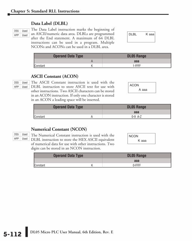
DL05 Micro PLC User Manual, 6th Edition, Rev. E5-112
Chapter 5: Standard RLL Instructions
Data Label (DLBL)The Data Label instruction marks the beginning of an ASCII/numeric data area. DLBLs are programmed after the End statement. A maximum of 64 DLBL instructions can be used in a program. Multiple NCONs and ACONs can be used in a DLBL area.
ASCII Constant (ACON)The ASCII Constant instruction is used with the DLBL instruction to store ASCII text for use with other instructions. Two ASCII characters can be stored in an ACON instruction. If only one character is stored in an ACON a leading space will be inserted.
Numerical Constant (NCON)The Numerical Constant instruction is used with the DLBL instruction to store the HEX ASCII equivalent of numerical data for use with other instructions. Two digits can be stored in an NCON instruction.
K aaaDLBL
A aaaACON
K aaaNCON
Operand Data Type DL05 Range ⸠⸠⸠⸠⸠⸠⸠⸠⸠⸠⸠⸠⸠⸠⸠⸠⸠⸠⸠⸠⸠⸠⸠⸠⸠⸠⸠⸠⸠⸠⸠⸠⸠⸠⸠⸠⸠⸠⸠⸠⸠⸠⸠⸠⸠⸠⸠⸠⸠⸠⸠⸠⸠⸠⸠⸠⸠⸠⸠⸠⸠⸠⸠⸠⸠⸠⸠⸠⸠⸠⸠⸠⸠A aaaConstant ⸠⸠⸠⸠⸠⸠⸠⸠⸠⸠⸠⸠⸠⸠⸠⸠⸠⸠⸠⸠⸠⸠⸠⸠⸠⸠⸠⸠⸠⸠⸠⸠⸠⸠⸠⸠⸠⸠⸠⸠⸠⸠⸠⸠⸠⸠⸠⸠⸠⸠⸠⸠⸠⸠⸠⸠⸠⸠⸠⸠⸠K 1-FFFF
Operand Data Type DL05 Rangeaaa
Constant ⸠⸠⸠⸠⸠⸠⸠⸠⸠⸠⸠⸠⸠⸠⸠⸠⸠⸠⸠⸠⸠⸠⸠⸠⸠⸠⸠⸠⸠⸠⸠⸠⸠⸠⸠⸠⸠⸠⸠⸠⸠⸠⸠⸠⸠⸠⸠⸠⸠⸠⸠⸠⸠⸠⸠⸠⸠⸠⸠⸠⸠A 0-9 A-Z
Operand Data Type DL05 Rangeaaa
Constant ⸠⸠⸠⸠⸠⸠⸠⸠⸠⸠⸠⸠⸠⸠⸠⸠⸠⸠⸠⸠⸠⸠⸠⸠⸠⸠⸠⸠⸠⸠⸠⸠⸠⸠⸠⸠⸠⸠⸠⸠⸠⸠⸠⸠⸠⸠⸠⸠⸠⸠⸠⸠⸠⸠⸠⸠⸠⸠⸠⸠⸠K 0-FFFF
DS5 Used
HPP Used
DS5 Used
HPP Used
DS5 Used
HPP Used
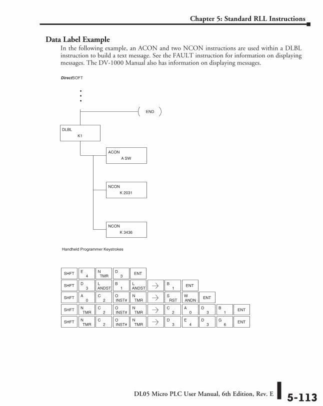
DL05 Micro PLC User Manual, 6th Edition, Rev. E 5-113
Chapter 5: Standard RLL Instructions
Data Label ExampleIn the following example, an ACON and two NCON instructions are used within a DLBL instruction to build a text message. See the FAULT instruction for information on displaying messages. The DV-1000 Manual also has information on displaying messages.
Direct SOFT32
Handheld Programmer Keystrokes
DLBL
K1
END
ACON
A SW
NCON
K 2031
NCON
K 3436
SHFT4
ETMR
N3
D ENT
SHFT3
DANDSTL
1B
ANDSTL
1B ENT
SHFT0
A2
CINST#O
TMRN
SHFTTMR
N2
CINST#O
TMRN
SHFTTMR
N2
CINST#O
TMRN
ENT3
D3
D4
E6
G
ENT3
D2
C0
A1
B
ENTRST
SANDNW
DirectSOFT
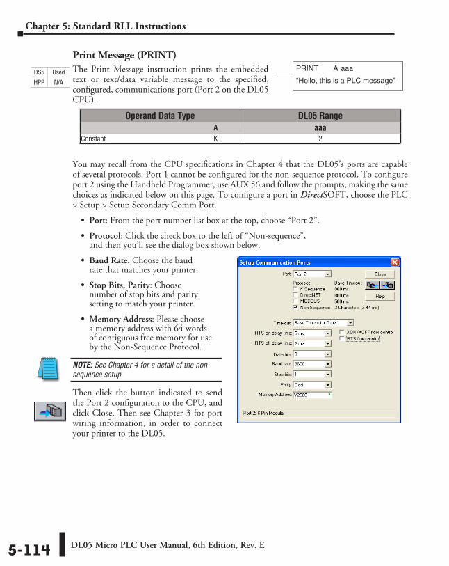
DL05 Micro PLC User Manual, 6th Edition, Rev. E5-114
Chapter 5: Standard RLL Instructions
Print Message (PRINT)The Print Message instruction prints the embedded text or text/data variable message to the specified, configured, communications port (Port 2 on the DL05 CPU).
You may recall from the CPU specifications in Chapter 4 that the DL05’s ports are capable of several protocols. Port 1 cannot be configured for the non-sequence protocol. To configure port 2 using the Handheld Programmer, use AUX 56 and follow the prompts, making the same choices as indicated below on this page. To configure a port in DirectSOFT, choose the PLC > Setup > Setup Secondary Comm Port.
• Port: From the port number list box at the top, choose “Port 2”.
• Protocol: Click the check box to the left of “Non-sequence”, and then you’ll see the dialog box shown below.
• Baud Rate: Choose the baud rate that matches your printer.
• Stop Bits, Parity: Choose number of stop bits and parity setting to match your printer.
• Memory Address: Please choose a memory address with 64 words of contiguous free memory for use by the Non-Sequence Protocol.
NOTE: See Chapter 4 for a detail of the non-sequence setup.
Then click the button indicated to send the Port 2 configuration to the CPU, and click Close. Then see Chapter 3 for port wiring information, in order to connect your printer to the DL05.
PRINT A aaa
“Hello, this is a PLC message”
Operand Data Type DL05 Range ⸠⸠⸠⸠⸠⸠⸠⸠⸠⸠⸠⸠⸠⸠⸠⸠⸠⸠⸠⸠⸠⸠⸠⸠⸠⸠⸠⸠⸠⸠⸠⸠⸠⸠⸠⸠⸠⸠⸠⸠⸠⸠⸠⸠⸠⸠⸠⸠⸠⸠⸠⸠⸠⸠⸠⸠⸠⸠⸠⸠⸠⸠⸠⸠⸠⸠⸠⸠⸠⸠⸠⸠⸠A aaaConstant ⸠⸠⸠⸠⸠⸠⸠⸠⸠⸠⸠⸠⸠⸠⸠⸠⸠⸠⸠⸠⸠⸠⸠⸠⸠⸠⸠⸠⸠⸠⸠⸠⸠⸠⸠⸠⸠⸠⸠⸠⸠⸠⸠⸠⸠⸠⸠⸠⸠⸠⸠⸠⸠⸠⸠⸠⸠⸠⸠⸠⸠K 2
DS5 Used
HPP N/A
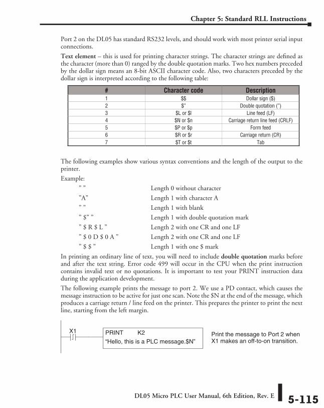
DL05 Micro PLC User Manual, 6th Edition, Rev. E 5-115
Chapter 5: Standard RLL Instructions
Port 2 on the DL05 has standard RS232 levels, and should work with most printer serial input connections.
Text element – this is used for printing character strings. The character strings are defined as the character (more than 0) ranged by the double quotation marks. Two hex numbers preceded by the dollar sign means an 8-bit ASCII character code. Also, two characters preceded by the dollar sign is interpreted according to the following table:
The following examples show various syntax conventions and the length of the output to the printer.
Example:
” ” Length 0 without character
”A” Length 1 with character A
” ” Length 1 with blank
” $” ” Length 1 with double quotation mark
” $ R $ L ” Length 2 with one CR and one LF
” $ 0 D $ 0 A ” Length 2 with one CR and one LF
” $ $ ” Length 1 with one $ mark
In printing an ordinary line of text, you will need to include double quotation marks before and after the text string. Error code 499 will occur in the CPU when the print instruction contains invalid text or no quotations. It is important to test your PRINT instruction data during the application development.
The following example prints the message to port 2. We use a PD contact, which causes the message instruction to be active for just one scan. Note the $N at the end of the message, which produces a carriage return / line feed on the printer. This prepares the printer to print the next line, starting from the left margin.
# Character code Description1 $$ Dollar sign ($)2 $” Double quotation (”)3 $L or $l Line feed (LF)4 $N or $n Carriage return line feed (CRLF)5 $P or $p Form feed6 $R or $r Carriage return (CR)7 $T or $t Tab
X1 Print the message to Port 2 whenX1 makes an off-to-on transition.
PRINT K2
“Hello, this is a PLC message.$N”
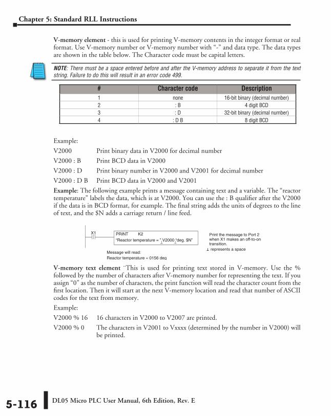
DL05 Micro PLC User Manual, 6th Edition, Rev. E5-116
Chapter 5: Standard RLL Instructions
V-memory element - this is used for printing V-memory contents in the integer format or real format. Use V-memory number or V-memory number with “-” and data type. The data types are shown in the table below. The Character code must be capital letters.
NOTE: There must be a space entered before and after the V-memory address to separate it from the text string. Failure to do this will result in an error code 499.
Example:
V2000 Print binary data in V2000 for decimal number
V2000 : B Print BCD data in V2000
V2000 : D Print binary number in V2000 and V2001 for decimal number
V2000 : D B Print BCD data in V2000 and V2001
Example: The following example prints a message containing text and a variable. The “reactor temperature” labels the data, which is at V2000. You can use the : B qualifier after the V2000 if the data is in BCD format, for example. The final string adds the units of degrees to the line of text, and the $N adds a carriage return / line feed.
V-memory text element ¨This is used for printing text stored in V-memory. Use the % followed by the number of characters after V-memory number for representing the text. If you assign “0” as the number of characters, the print function will read the character count from the first location. Then it will start at the next V-memory location and read that number of ASCII codes for the text from memory.
Example:
V2000 % 16 16 characters in V2000 to V2007 are printed.
V2000 % 0 The characters in V2001 to Vxxxx (determined by the number in V2000) will be printed.
# Character code Description1 none 16-bit binary (decimal number)2 : B 4 digit BCD3 : D 32-bit binary (decimal number)4 : D B 8 digit BCD
X1 Print the message to Port 2when X1 makes an off-to-ontransition.
PRINT K2
“Reactor temperature = ” V2000 “deg. $N”⊥ ⊥
Message will read:Reactor temperature = 0156 deg
⊥ represents a space
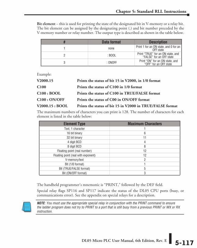
DL05 Micro PLC User Manual, 6th Edition, Rev. E 5-117
Chapter 5: Standard RLL Instructions
Bit element – this is used for printing the state of the designated bit in V-memory or a relay bit. The bit element can be assigned by the designating point (.) and bit number preceded by the V-memory number or relay number. The output type is described as shown in the table below.
Example:
V2000.15 Prints the status of bit 15 in V2000, in 1/0 format
C100 Prints the status of C100 in 1/0 format
C100 : BOOL Prints the status of C100 in TRUE/FALSE format
C100 : ON/OFF Prints the status of C00 in ON/OFF format
V2000.15 : BOOL Prints the status of bit 15 in V2000 in TRUE/FALSE format
The maximum numbers of characters you can print is 128. The number of characters for each element is listed in the table below:
The handheld programmer’s mnemonic is “PRINT,” followed by the DEF field.
Special relay flags SP116 and SP117 indicate the status of the DL05 CPU ports (busy, or communications error). See the appendix on special relays for a description.
NOTE: You must use the appropriate special relay in conjunction with the PRINT command to ensure the ladder program does not try to PRINT to a port that is still busy from a previous PRINT or WX or RX instruction.
# Data format Description1 none Print 1 for an ON state, and 0 for an
OFF state
2 : BOOL Print “TRUE” for an ON state, and “FALSE” for an OFF state
3 : ONOFF Print “ON” for an ON state, and “OFF” for an OFF state
Element Type Maximum CharactersText, 1 character 1
16 bit binary 632 bit binary 114 digit BCD 48 digit BCD 8
Floating point (real number) 12Floating point (real with exponent) 12
V-memory/text 2Bit (1/0 format) 1
Bit (TRUE/FALSE format) 5Bit (ON/OFF format) 3
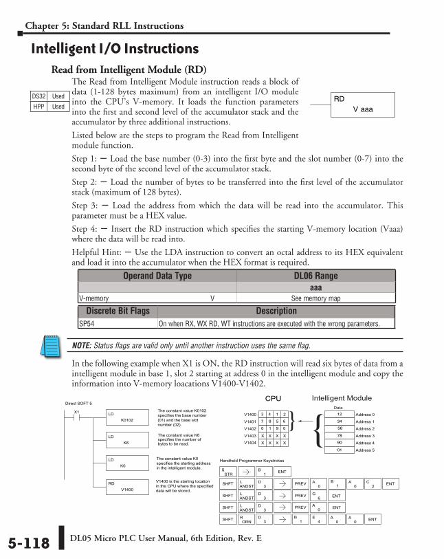
DL05 Micro PLC User Manual, 6th Edition, Rev. E5-118
Chapter 5: Standard RLL Instructions
Intelligent I/O InstructionsRead from Intelligent Module (RD)
The Read from Intelligent Module instruction reads a block of data (1-128 bytes maximum) from an intelligent I/O module into the CPU’s V-memory. It loads the function parameters into the first and second level of the accumulator stack and the accumulator by three additional instructions.
Listed below are the steps to program the Read from Intelligent module function.
Step 1: S Load the base number (0-3) into the first byte and the slot number (0-7) into the second byte of the second level of the accumulator stack.
Step 2: S Load the number of bytes to be transferred into the first level of the accumulator stack (maximum of 128 bytes).
Step 3: S Load the address from which the data will be read into the accumulator. This parameter must be a HEX value.
Step 4: S Insert the RD instruction which specifies the starting V-memory location (Vaaa) where the data will be read into.
Helpful Hint: S Use the LDA instruction to convert an octal address to its HEX equivalent and load it into the accumulator when the HEX format is required.
NOTE: Status flags are valid only until another instruction uses the same flag.
In the following example when X1 is ON, the RD instruction will read six bytes of data from a intelligent module in base 1, slot 2 starting at address 0 in the intelligent module and copy the information into V-memory loacations V1400-V1402.
DS32 Used
HPP Used V aaaRD
Direct SOFT 5
Handheld Programmer Keystrokes
LDK0102
X1 The constant value K0102specifies the base number(01) and the base slot number (02).
LDK6
The constant value K6specifies the number ofbytes to be read.
LDK0
RDV1400
V1400 is the starting locationin the CPU where the specifieddata will be stored.
Address 2
Address 3
1 9
Address 4
0
Address 5
Address 0
Address 1
3 4
7
V1402
6
V1403
V1404
V1400
V1401
STR$
SHFT ANDSTL
3D PREV
SHFT ANDSTL
3D
6G ENT
SHFT ORNR
1B ENT
0A ENT
4E
0A
0A ENT
SHFT ANDSTL
3D PREV 0
A0
A ENT2C
CPU
The constant value K0specifies the starting addressin the intelligent module.
1 2
8 5
0
X X X X
X X X X
12
56
34
78
90
01
{1
B
PREV
1B
}Intelligent Module
Data
3D
Operand Data Type DL06 Rangeaaa
V-memory ⸠⸠⸠⸠⸠⸠⸠⸠⸠⸠⸠⸠⸠⸠⸠⸠⸠⸠⸠⸠⸠⸠⸠⸠⸠⸠⸠⸠⸠⸠⸠⸠⸠⸠⸠⸠⸠⸠⸠⸠⸠⸠⸠⸠⸠⸠⸠⸠⸠⸠⸠⸠⸠⸠⸠⸠⸠⸠V See memory map
Discrete Bit Flags DescriptionSP54 On when RX, WX RD, WT instructions are executed with the wrong parameters.
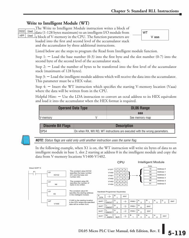
DL05 Micro PLC User Manual, 6th Edition, Rev. E 5-119
Chapter 5: Standard RLL Instructions
Write to Intelligent Module (WT)The Write to Intelligent Module instruction writes a block of data (1-128 bytes maximum) to an intelligent I/O module from a block of V-memory in the CPU. The function parameters are loaded into the first and second level of the accumulator stack and the accumulator by three additional instructions.
Listed below are the steps to program the Read from Intelligent module function.
Step 1: S Load the base number (0-3) into the first byte and the slot number (0-7) into the second byte of the second level of the accumulator stack.
Step 2: S Load the number of bytes to be transferred into the first level of the accumulator stack (maximum of 128 bytes).
Step 3: S Load the intelligent module address which will receive the data into the accumulator. This parameter must be a HEX value.
Step 4: S Insert the WT instruction which specifies the starting V-memory location (Vaaa) where the data will be written from in the CPU.
Helpful Hint: S Use the LDA instruction to convert an octal address to its HEX equivalent and load it into the accumulator when the HEX format is required.
NOTE: Status flags are valid only until another instruction uses the same flag.
In the following example, when X1 is on, the WT instruction will write six bytes of data to an intelligent module in base 1, slot 2 starting at address 0 in the intelligent module and copy the data from V-memory locations V1400-V1402.
V aaaWTDS32 Used
HPP Used
Direct SOFT 5
Handheld Programmer Keystrokes
LDK0102
X1 The constant value K0102specifies the base number(01) and the base slot number (02).
LDK6
The constant value K6specifies the number ofbytes to be written.
LDK0
WTV1400
V1400 is the starting locationin the CPU where the specifieddata will be written from.
Address 2
Address 31 9Address 4
0
Address 5
Address 0
Address 13 4
7
V1402
6
V1403
V1404
V1400
V1401
STR$
SHFT ANDSTL
3D PREV
SHFT ANDSTL
3D
6G ENT
SHFT ANDNW
1B ENT
0A ENT
4E
0A
0A ENT
SHFT ANDSTL
3D PREV 0
A0
A ENT2C
CPU
The constant value K0specifies the starting addressin the intelligent module.
1 2
8 5
0
X X X X
X X X X
12
56
34
78
90
01
{1
B
PREV
1B
}
Intelligent ModuleData
MLRT
V1377 X X X X
Operand Data Type DL06 Rangeaaa
V-memory ⸠⸠⸠⸠⸠⸠⸠⸠⸠⸠⸠⸠⸠⸠⸠⸠⸠⸠⸠⸠⸠⸠⸠⸠⸠⸠⸠⸠⸠⸠⸠⸠⸠⸠⸠⸠⸠⸠⸠⸠⸠⸠⸠⸠⸠⸠⸠⸠⸠⸠⸠⸠⸠⸠⸠⸠⸠⸠V See memory map
Discrete Bit Flags DescriptionSP54 On when RX, WX RD, WT instructions are executed with the wrong parameters.
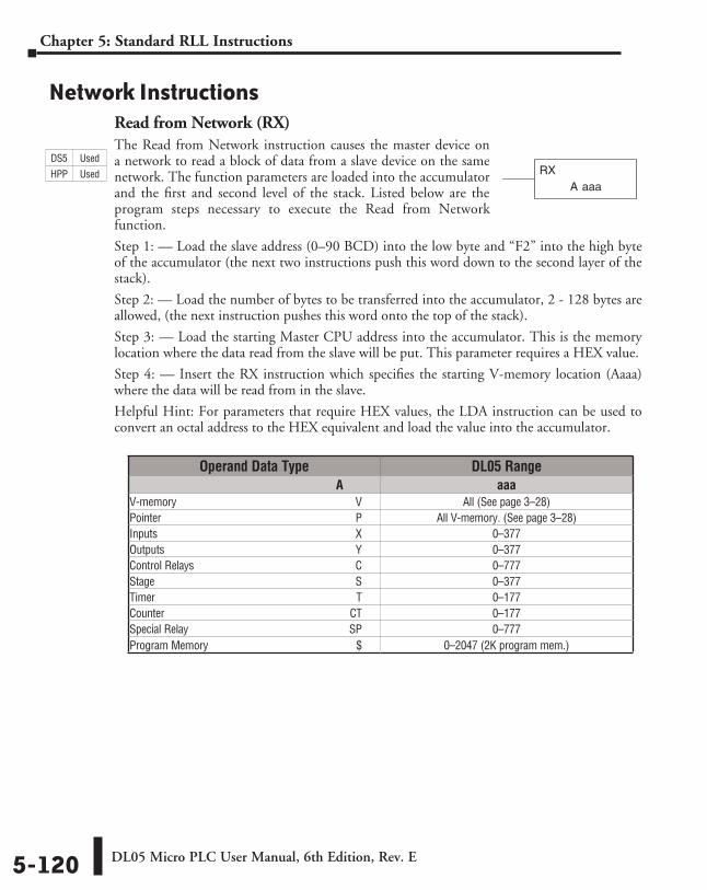
DL05 Micro PLC User Manual, 6th Edition, Rev. E5-120
Chapter 5: Standard RLL Instructions
Network InstructionsRead from Network (RX)The Read from Network instruction causes the master device on a network to read a block of data from a slave device on the same network. The function parameters are loaded into the accumulator and the first and second level of the stack. Listed below are the program steps necessary to execute the Read from Network function.
Step 1: — Load the slave address (0–90 BCD) into the low byte and “F2” into the high byte of the accumulator (the next two instructions push this word down to the second layer of the stack).
Step 2: — Load the number of bytes to be transferred into the accumulator, 2 - 128 bytes are allowed, (the next instruction pushes this word onto the top of the stack).
Step 3: — Load the starting Master CPU address into the accumulator. This is the memory location where the data read from the slave will be put. This parameter requires a HEX value.
Step 4: — Insert the RX instruction which specifies the starting V-memory location (Aaaa) where the data will be read from in the slave.
Helpful Hint: For parameters that require HEX values, the LDA instruction can be used to convert an octal address to the HEX equivalent and load the value into the accumulator.
A aaaRX
Operand Data Type DL05 Range A aaaV-memory ⸠⸠⸠⸠⸠⸠⸠⸠⸠⸠⸠⸠⸠⸠⸠⸠⸠⸠⸠⸠⸠⸠⸠⸠⸠⸠⸠⸠⸠⸠⸠⸠⸠⸠⸠⸠⸠⸠⸠⸠⸠⸠⸠⸠⸠⸠⸠⸠⸠⸠⸠⸠⸠⸠⸠⸠⸠⸠⸠⸠⸠⸠⸠⸠ V All (See page 3–28)Pointer ⸠⸠⸠⸠⸠⸠⸠⸠⸠⸠⸠⸠⸠⸠⸠⸠⸠⸠⸠⸠⸠⸠⸠⸠⸠⸠⸠⸠⸠⸠⸠⸠⸠⸠⸠⸠⸠⸠⸠⸠⸠⸠⸠⸠⸠⸠⸠⸠⸠⸠⸠⸠⸠⸠⸠⸠⸠⸠⸠⸠⸠⸠⸠⸠⸠⸠⸠⸠⸠⸠ P All V-memory. (See page 3–28)Inputs ⸠⸠⸠⸠⸠⸠⸠⸠⸠⸠⸠⸠⸠⸠⸠⸠⸠⸠⸠⸠⸠⸠⸠⸠⸠⸠⸠⸠⸠⸠⸠⸠⸠⸠⸠⸠⸠⸠⸠⸠⸠⸠⸠⸠⸠⸠⸠⸠⸠⸠⸠⸠⸠⸠⸠⸠⸠⸠⸠⸠⸠⸠⸠⸠⸠⸠⸠⸠⸠⸠⸠ X 0–377Outputs ⸠⸠⸠⸠⸠⸠⸠⸠⸠⸠⸠⸠⸠⸠⸠⸠⸠⸠⸠⸠⸠⸠⸠⸠⸠⸠⸠⸠⸠⸠⸠⸠⸠⸠⸠⸠⸠⸠⸠⸠⸠⸠⸠⸠⸠⸠⸠⸠⸠⸠⸠⸠⸠⸠⸠⸠⸠⸠⸠⸠⸠⸠⸠⸠⸠⸠⸠⸠⸠ Y 0–377Control Relays ⸠⸠⸠⸠⸠⸠⸠⸠⸠⸠⸠⸠⸠⸠⸠⸠⸠⸠⸠⸠⸠⸠⸠⸠⸠⸠⸠⸠⸠⸠⸠⸠⸠⸠⸠⸠⸠⸠⸠⸠⸠⸠⸠⸠⸠⸠⸠⸠⸠⸠⸠⸠⸠⸠⸠⸠⸠⸠ C 0–777Stage ⸠⸠⸠⸠⸠⸠⸠⸠⸠⸠⸠⸠⸠⸠⸠⸠⸠⸠⸠⸠⸠⸠⸠⸠⸠⸠⸠⸠⸠⸠⸠⸠⸠⸠⸠⸠⸠⸠⸠⸠⸠⸠⸠⸠⸠⸠⸠⸠⸠⸠⸠⸠⸠⸠⸠⸠⸠⸠⸠⸠⸠⸠⸠⸠⸠⸠⸠⸠⸠⸠⸠⸠ S 0–377Timer ⸠⸠⸠⸠⸠⸠⸠⸠⸠⸠⸠⸠⸠⸠⸠⸠⸠⸠⸠⸠⸠⸠⸠⸠⸠⸠⸠⸠⸠⸠⸠⸠⸠⸠⸠⸠⸠⸠⸠⸠⸠⸠⸠⸠⸠⸠⸠⸠⸠⸠⸠⸠⸠⸠⸠⸠⸠⸠⸠⸠⸠⸠⸠⸠⸠⸠⸠⸠⸠⸠⸠⸠ T 0–177Counter ⸠⸠⸠⸠⸠⸠⸠⸠⸠⸠⸠⸠⸠⸠⸠⸠⸠⸠⸠⸠⸠⸠⸠⸠⸠⸠⸠⸠⸠⸠⸠⸠⸠⸠⸠⸠⸠⸠⸠⸠⸠⸠⸠⸠⸠⸠⸠⸠⸠⸠⸠⸠⸠⸠⸠⸠⸠⸠⸠⸠⸠⸠⸠⸠⸠⸠⸠CT 0–177Special Relay ⸠⸠⸠⸠⸠⸠⸠⸠⸠⸠⸠⸠⸠⸠⸠⸠⸠⸠⸠⸠⸠⸠⸠⸠⸠⸠⸠⸠⸠⸠⸠⸠⸠⸠⸠⸠⸠⸠⸠⸠⸠⸠⸠⸠⸠⸠⸠⸠⸠⸠⸠⸠⸠⸠⸠⸠⸠⸠SP 0–777Program Memory ⸠⸠⸠⸠⸠⸠⸠⸠⸠⸠⸠⸠⸠⸠⸠⸠⸠⸠⸠⸠⸠⸠⸠⸠⸠⸠⸠⸠⸠⸠⸠⸠⸠⸠⸠⸠⸠⸠⸠⸠⸠⸠⸠⸠⸠⸠⸠⸠⸠⸠⸠⸠ $ 0–2047 (2K program mem.)
DS5 Used
HPP Used
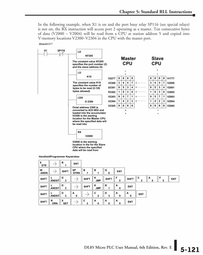
DL05 Micro PLC User Manual, 6th Edition, Rev. E 5-121
Chapter 5: Standard RLL Instructions
In the following example, when X1 is on and the port busy relay SP116 (see special relays) is not on, the RX instruction will access port 2 operating as a master. Ten consecutive bytes of data (V2000 – V2004) will be read from a CPU at station address 5 and copied into V-memory locations V2300–V2304 in the CPU with the master port.
DirectSOFT
Handheld Programmer Keystrokes
LDKF205
X1
The constant value KF205specifies the port number (2)and the slave address (5)
LDK10
The constant value K10specifies the number ofbytes to be read (2-128 bytes allowed)
LDAO 2300
Octal address 2300 isconverted to 4C0 HEX andloaded into the accumulator.V2300 is the startinglocation for the Master CPUwhere the specified data willbe read into
RXV2000
V2000 is the startinglocation in the for the SlaveCPU where the specifieddata will be read from
V20018 5 3 4
V20021 9 3 6
V20039 5 7 1
V20041 4 2 3
V1777X X X X
V20003 4 5 7
Master
SP116
V2005X X X X
V2301 8 5 3 4
V2302 1 9 3 6
V2303 9 5 7 1
V2304 1 4 2 3
V2277 X X X X
V2300 3 4 5 7
V2305 X X X X
SlaveCPU
STR$
SHFT ANDSTL
3D SHFT JMP
K
SHFT ANDSTL
3D
ANDNW SHFT STRN
SP1
B1
B6
G ENT
1B
0A ENT
0A
SHFT ORNR
SETX
1B ENT
2C
3D
0A
0A ENT
2C
0A
0A
0A ENT
SHFT ANDSTL
3D SHFT JMP
K0
A ENT2C
5FSHFT SHFT5
F
CPU
DirectSOFT
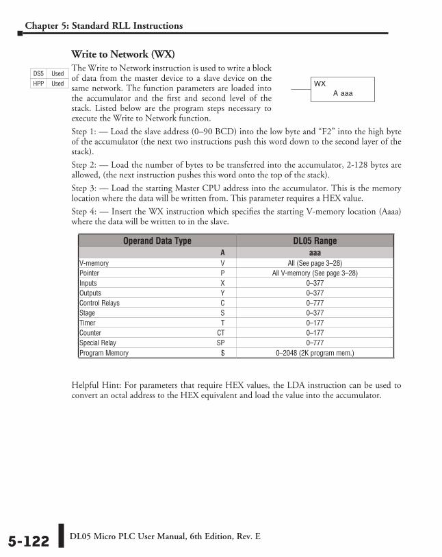
DL05 Micro PLC User Manual, 6th Edition, Rev. E5-122
Chapter 5: Standard RLL Instructions
Write to Network (WX)The Write to Network instruction is used to write a block of data from the master device to a slave device on the same network. The function parameters are loaded into the accumulator and the first and second level of the stack. Listed below are the program steps necessary to execute the Write to Network function.
Step 1: — Load the slave address (0–90 BCD) into the low byte and “F2” into the high byte of the accumulator (the next two instructions push this word down to the second layer of the stack).
Step 2: — Load the number of bytes to be transferred into the accumulator, 2-128 bytes are allowed, (the next instruction pushes this word onto the top of the stack).
Step 3: — Load the starting Master CPU address into the accumulator. This is the memory location where the data will be written from. This parameter requires a HEX value.
Step 4: — Insert the WX instruction which specifies the starting V-memory location (Aaaa) where the data will be written to in the slave.
Helpful Hint: For parameters that require HEX values, the LDA instruction can be used to convert an octal address to the HEX equivalent and load the value into the accumulator.
A aaaWX
Operand Data Type DL05 Range ⸠⸠⸠⸠⸠⸠⸠⸠⸠⸠⸠⸠⸠⸠⸠⸠⸠⸠⸠⸠⸠⸠⸠⸠⸠⸠⸠⸠⸠⸠⸠⸠⸠⸠⸠⸠⸠⸠⸠⸠⸠⸠⸠⸠⸠⸠⸠⸠⸠⸠⸠⸠⸠⸠⸠⸠⸠⸠⸠⸠⸠⸠⸠⸠⸠⸠⸠⸠⸠⸠⸠⸠⸠⸠⸠⸠⸠⸠⸠ A aaaV-memory ⸠⸠⸠⸠⸠⸠⸠⸠⸠⸠⸠⸠⸠⸠⸠⸠⸠⸠⸠⸠⸠⸠⸠⸠⸠⸠⸠⸠⸠⸠⸠⸠⸠⸠⸠⸠⸠⸠⸠⸠⸠⸠⸠⸠⸠⸠⸠⸠⸠⸠⸠⸠⸠⸠⸠⸠⸠⸠⸠⸠⸠⸠⸠⸠ V All (See page 3–28)Pointer ⸠⸠⸠⸠⸠⸠⸠⸠⸠⸠⸠⸠⸠⸠⸠⸠⸠⸠⸠⸠⸠⸠⸠⸠⸠⸠⸠⸠⸠⸠⸠⸠⸠⸠⸠⸠⸠⸠⸠⸠⸠⸠⸠⸠⸠⸠⸠⸠⸠⸠⸠⸠⸠⸠⸠⸠⸠⸠⸠⸠⸠⸠⸠⸠⸠⸠⸠⸠⸠⸠ P All V-memory (See page 3–28)Inputs ⸠⸠⸠⸠⸠⸠⸠⸠⸠⸠⸠⸠⸠⸠⸠⸠⸠⸠⸠⸠⸠⸠⸠⸠⸠⸠⸠⸠⸠⸠⸠⸠⸠⸠⸠⸠⸠⸠⸠⸠⸠⸠⸠⸠⸠⸠⸠⸠⸠⸠⸠⸠⸠⸠⸠⸠⸠⸠⸠⸠⸠⸠⸠⸠⸠⸠⸠⸠⸠⸠⸠ X 0–377Outputs ⸠⸠⸠⸠⸠⸠⸠⸠⸠⸠⸠⸠⸠⸠⸠⸠⸠⸠⸠⸠⸠⸠⸠⸠⸠⸠⸠⸠⸠⸠⸠⸠⸠⸠⸠⸠⸠⸠⸠⸠⸠⸠⸠⸠⸠⸠⸠⸠⸠⸠⸠⸠⸠⸠⸠⸠⸠⸠⸠⸠⸠⸠⸠⸠⸠⸠⸠⸠⸠ Y 0–377Control Relays ⸠⸠⸠⸠⸠⸠⸠⸠⸠⸠⸠⸠⸠⸠⸠⸠⸠⸠⸠⸠⸠⸠⸠⸠⸠⸠⸠⸠⸠⸠⸠⸠⸠⸠⸠⸠⸠⸠⸠⸠⸠⸠⸠⸠⸠⸠⸠⸠⸠⸠⸠⸠⸠⸠⸠⸠⸠⸠ C 0–777Stage ⸠⸠⸠⸠⸠⸠⸠⸠⸠⸠⸠⸠⸠⸠⸠⸠⸠⸠⸠⸠⸠⸠⸠⸠⸠⸠⸠⸠⸠⸠⸠⸠⸠⸠⸠⸠⸠⸠⸠⸠⸠⸠⸠⸠⸠⸠⸠⸠⸠⸠⸠⸠⸠⸠⸠⸠⸠⸠⸠⸠⸠⸠⸠⸠⸠⸠⸠⸠⸠⸠⸠⸠ S 0–377Timer ⸠⸠⸠⸠⸠⸠⸠⸠⸠⸠⸠⸠⸠⸠⸠⸠⸠⸠⸠⸠⸠⸠⸠⸠⸠⸠⸠⸠⸠⸠⸠⸠⸠⸠⸠⸠⸠⸠⸠⸠⸠⸠⸠⸠⸠⸠⸠⸠⸠⸠⸠⸠⸠⸠⸠⸠⸠⸠⸠⸠⸠⸠⸠⸠⸠⸠⸠⸠⸠⸠⸠⸠ T 0–177Counter ⸠⸠⸠⸠⸠⸠⸠⸠⸠⸠⸠⸠⸠⸠⸠⸠⸠⸠⸠⸠⸠⸠⸠⸠⸠⸠⸠⸠⸠⸠⸠⸠⸠⸠⸠⸠⸠⸠⸠⸠⸠⸠⸠⸠⸠⸠⸠⸠⸠⸠⸠⸠⸠⸠⸠⸠⸠⸠⸠⸠⸠⸠⸠⸠⸠⸠⸠CT 0–177Special Relay ⸠⸠⸠⸠⸠⸠⸠⸠⸠⸠⸠⸠⸠⸠⸠⸠⸠⸠⸠⸠⸠⸠⸠⸠⸠⸠⸠⸠⸠⸠⸠⸠⸠⸠⸠⸠⸠⸠⸠⸠⸠⸠⸠⸠⸠⸠⸠⸠⸠⸠⸠⸠⸠⸠⸠⸠⸠⸠SP 0–777Program Memory ⸠⸠⸠⸠⸠⸠⸠⸠⸠⸠⸠⸠⸠⸠⸠⸠⸠⸠⸠⸠⸠⸠⸠⸠⸠⸠⸠⸠⸠⸠⸠⸠⸠⸠⸠⸠⸠⸠⸠⸠⸠⸠⸠⸠⸠⸠⸠⸠⸠⸠⸠⸠ $ 0–2048 (2K program mem.)
DS5 Used
HPP Used
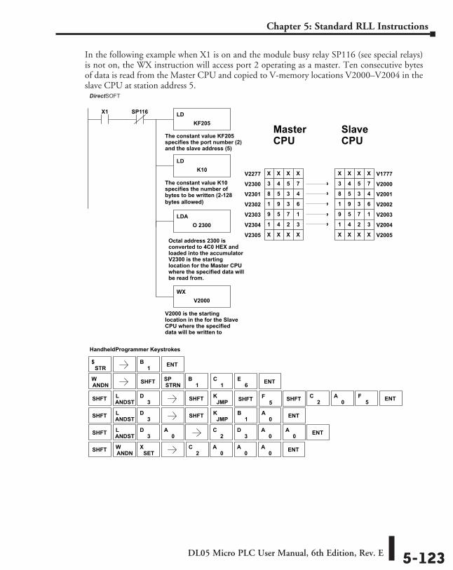
DL05 Micro PLC User Manual, 6th Edition, Rev. E 5-123
Chapter 5: Standard RLL Instructions
In the following example when X1 is on and the module busy relay SP116 (see special relays) is not on, the WX instruction will access port 2 operating as a master. Ten consecutive bytes of data is read from the Master CPU and copied to V-memory locations V2000–V2004 in the slave CPU at station address 5.
DirectSOFT
Handheld Programmer Keystrokes
LDKF205
X1
The constant value KF205specifies the port number (2)and the slave address (5)
LDK10
The constant value K10specifies the number ofbytes to be written (2-128bytes allowed)
LDAO 2300
WXV2000
V2000 is the startinglocation in the for the SlaveCPU where the specifieddata will be written to
V20018 5 3 4
V20021 9 3 6
V20039 5 7 1
V20041 4 2 3
V1777X X X X
V20003 4 5 7
MasterCPU
SP116
V2005X X X X
V2301 8 5 3 4
V2302 1 9 3 6
V2303 9 5 7 1
V2304 1 4 2 3
V2277 X X X X
V2300 3 4 5 7
V2305 X X X X
SlaveCPU
Octal address 2300 isconverted to 4C0 HEX andloaded into the accumulator
.
V2300 is the startinglocation for the Master CPUwhere the specified data willbe read from.
STR$
SHFT ANDSTL
3D SHFT JMP
K
SHFT ANDSTL
3D
ANDNW SHFT STRN
SP1
B1
C6
E ENT
1B
0A ENT
SHFT
0A
5F
2C
3D
0A
0A ENT
SHFT
SHFT
2C
0A
0A
0A ENTSET
XANDNW
SHFT ANDSTL
3D SHFT JMP
K0
A ENT2C
5F
1B ENT
DirectSOFT
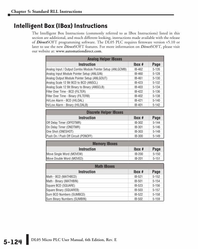
DL05 Micro PLC User Manual, 6th Edition, Rev. E5-124
Chapter 5: Standard RLL Instructions
Intelligent Box (IBox) InstructionsThe Intelligent Box Instructions (commonly referred to as IBox Instructions) listed in this section are additional, and much different looking, instructions made available with the release of DirectSOFT programming software. The DL05 PLC requires firmware version v5.10 or later to use the new DirectSOFT features. For more information on DirectSOFT, please visit our website at: www.automationdirect.com.
Analog Helper IBoxesInstruction Ibox # Page
Analog Input / Output Combo Module Pointer Setup (ANLGCMB) IB-462 5-126Analog Input Module Pointer Setup (ANLGIN) IB-460 5-128Analog Output Module Pointer Setup (ANLGOUT) IB-461 5-130Analog Scale 12 Bit BCD to BCD (ANSCL) IB-423 5-132Analog Scale 12 Bit Binary to Binary (ANSCLB) IB-403 5-134Filter Over Time - BCD (FILTER) IB-422 5-136Filter Over Time - Binary (FILTERB) IB-402 5-138Hi/Low Alarm - BCD (HILOAL) IB-421 5-140Hi/Low Alarm - Binary (HILOALB) IB-401 5-142
Discrete Helper IBoxesInstruction Ibox # Page
Off Delay Timer (OFFDTMR) IB-302 5-144On Delay Timer (ONDTMR) IB-301 5-146One Shot (ONESHOT) IB-303 5-148Push On / Push Off Circuit (PONOFF) IB-300 5-149
Memory IBoxesInstruction Ibox # Page
Move Single Word (MOVEW) IB-200 5-150Move Double Word (MOVED) IB-201 5-151
Math IBoxesInstruction Ibox # Page
Math - BCD (MATHBCD) IB-521 5-152Math - Binary (MATHBIN) IB-501 5-154Square BCD (SQUARE) IB-523 5-156Square Binary (SQUAREB) IB-503 5-157Sum BCD Numbers (SUMBCD) IB-522 5-158Sum Binary Numbers (SUMBIN) IB-502 5-159
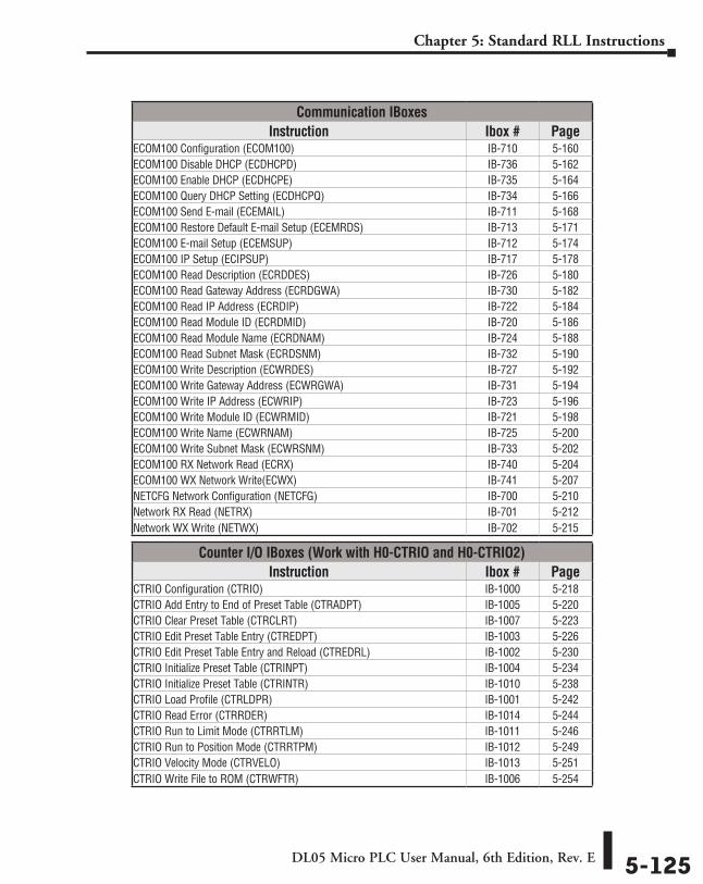
DL05 Micro PLC User Manual, 6th Edition, Rev. E 5-125
Chapter 5: Standard RLL Instructions
Communication IBoxesInstruction Ibox # Page
ECOM100 Configuration (ECOM100) IB-710 5-160ECOM100 Disable DHCP (ECDHCPD) IB-736 5-162ECOM100 Enable DHCP (ECDHCPE) IB-735 5-164ECOM100 Query DHCP Setting (ECDHCPQ) IB-734 5-166ECOM100 Send E-mail (ECEMAIL) IB-711 5-168ECOM100 Restore Default E-mail Setup (ECEMRDS) IB-713 5-171ECOM100 E-mail Setup (ECEMSUP) IB-712 5-174ECOM100 IP Setup (ECIPSUP) IB-717 5-178ECOM100 Read Description (ECRDDES) IB-726 5-180ECOM100 Read Gateway Address (ECRDGWA) IB-730 5-182ECOM100 Read IP Address (ECRDIP) IB-722 5-184ECOM100 Read Module ID (ECRDMID) IB-720 5-186ECOM100 Read Module Name (ECRDNAM) IB-724 5-188ECOM100 Read Subnet Mask (ECRDSNM) IB-732 5-190ECOM100 Write Description (ECWRDES) IB-727 5-192ECOM100 Write Gateway Address (ECWRGWA) IB-731 5-194ECOM100 Write IP Address (ECWRIP) IB-723 5-196ECOM100 Write Module ID (ECWRMID) IB-721 5-198ECOM100 Write Name (ECWRNAM) IB-725 5-200ECOM100 Write Subnet Mask (ECWRSNM) IB-733 5-202ECOM100 RX Network Read (ECRX) IB-740 5-204ECOM100 WX Network Write(ECWX) IB-741 5-207NETCFG Network Configuration (NETCFG) IB-700 5-210Network RX Read (NETRX) IB-701 5-212Network WX Write (NETWX) IB-702 5-215
Counter I/O IBoxes (Work with H0-CTRIO and H0-CTRIO2)Instruction Ibox # Page
CTRIO Configuration (CTRIO) IB-1000 5-218CTRIO Add Entry to End of Preset Table (CTRADPT) IB-1005 5-220CTRIO Clear Preset Table (CTRCLRT) IB-1007 5-223CTRIO Edit Preset Table Entry (CTREDPT) IB-1003 5-226CTRIO Edit Preset Table Entry and Reload (CTREDRL) IB-1002 5-230CTRIO Initialize Preset Table (CTRINPT) IB-1004 5-234CTRIO Initialize Preset Table (CTRINTR) IB-1010 5-238CTRIO Load Profile (CTRLDPR) IB-1001 5-242CTRIO Read Error (CTRRDER) IB-1014 5-244CTRIO Run to Limit Mode (CTRRTLM) IB-1011 5-246CTRIO Run to Position Mode (CTRRTPM) IB-1012 5-249CTRIO Velocity Mode (CTRVELO) IB-1013 5-251CTRIO Write File to ROM (CTRWFTR) IB-1006 5-254
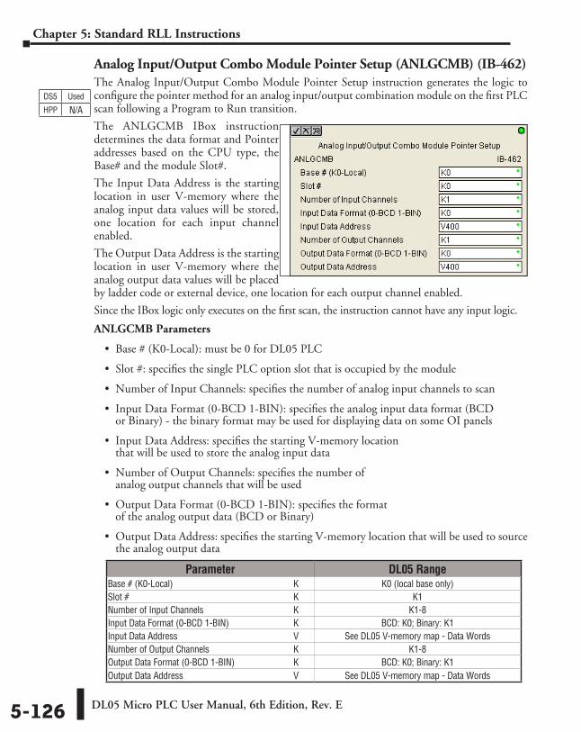
DL05 Micro PLC User Manual, 6th Edition, Rev. E5-126
Chapter 5: Standard RLL Instructions
Analog Input/Output Combo Module Pointer Setup (ANLGCMB) (IB-462)The Analog Input/Output Combo Module Pointer Setup instruction generates the logic to configure the pointer method for an analog input/output combination module on the first PLC scan following a Program to Run transition.
The ANLGCMB IBox instruction determines the data format and Pointer addresses based on the CPU type, the Base# and the module Slot#.
The Input Data Address is the starting location in user V-memory where the analog input data values will be stored, one location for each input channel enabled.
The Output Data Address is the starting location in user V-memory where the analog output data values will be placed by ladder code or external device, one location for each output channel enabled.
Since the IBox logic only executes on the first scan, the instruction cannot have any input logic.
ANLGCMB Parameters
• Base # (K0-Local): must be 0 for DL05 PLC
• Slot #: specifies the single PLC option slot that is occupied by the module
• Number of Input Channels: specifies the number of analog input channels to scan
• Input Data Format (0-BCD 1-BIN): specifies the analog input data format (BCD or Binary) - the binary format may be used for displaying data on some OI panels
• Input Data Address: specifies the starting V-memory location that will be used to store the analog input data
• Number of Output Channels: specifies the number of analog output channels that will be used
• Output Data Format (0-BCD 1-BIN): specifies the format of the analog output data (BCD or Binary)
• Output Data Address: specifies the starting V-memory location that will be used to source the analog output data
DS5 Used
HPP N/A
Parameter DL05 RangeBase # (K0-Local) ⸠⸠⸠⸠⸠⸠⸠⸠⸠⸠⸠⸠⸠⸠⸠⸠⸠⸠⸠⸠⸠⸠⸠⸠⸠⸠⸠⸠⸠⸠⸠⸠⸠⸠⸠⸠⸠⸠⸠⸠⸠⸠⸠⸠⸠⸠⸠⸠⸠⸠⸠⸠ K K0 (local base only)Slot # ⸠⸠⸠⸠⸠⸠⸠⸠⸠⸠⸠⸠⸠⸠⸠⸠⸠⸠⸠⸠⸠⸠⸠⸠⸠⸠⸠⸠⸠⸠⸠⸠⸠⸠⸠⸠⸠⸠⸠⸠⸠⸠⸠⸠⸠⸠⸠⸠⸠⸠⸠⸠⸠⸠⸠⸠⸠⸠⸠⸠⸠⸠⸠⸠⸠⸠⸠⸠⸠⸠⸠⸠ K K1Number of Input Channels ⸠⸠⸠⸠⸠⸠⸠⸠⸠⸠⸠⸠⸠⸠⸠⸠⸠⸠⸠⸠⸠⸠⸠⸠⸠⸠⸠⸠⸠⸠⸠⸠⸠⸠⸠⸠⸠⸠ K K1-8Input Data Format (0-BCD 1-BIN) ⸠⸠⸠⸠⸠⸠⸠⸠⸠⸠⸠⸠⸠⸠⸠⸠⸠⸠⸠⸠⸠⸠⸠⸠⸠⸠⸠⸠ K BCD: K0; Binary: K1Input Data Address ⸠⸠⸠⸠⸠⸠⸠⸠⸠⸠⸠⸠⸠⸠⸠⸠⸠⸠⸠⸠⸠⸠⸠⸠⸠⸠⸠⸠⸠⸠⸠⸠⸠⸠⸠⸠⸠⸠⸠⸠⸠⸠⸠⸠⸠⸠⸠⸠⸠⸠ V See DL05 V-memory map - Data WordsNumber of Output Channels ⸠⸠⸠⸠⸠⸠⸠⸠⸠⸠⸠⸠⸠⸠⸠⸠⸠⸠⸠⸠⸠⸠⸠⸠⸠⸠⸠⸠⸠⸠⸠⸠⸠⸠⸠⸠ K K1-8Output Data Format (0-BCD 1-BIN) ⸠⸠⸠⸠⸠⸠⸠⸠⸠⸠⸠⸠⸠⸠⸠⸠⸠⸠⸠⸠⸠⸠⸠⸠ K BCD: K0; Binary: K1 Output Data Address ⸠⸠⸠⸠⸠⸠⸠⸠⸠⸠⸠⸠⸠⸠⸠⸠⸠⸠⸠⸠⸠⸠⸠⸠⸠⸠⸠⸠⸠⸠⸠⸠⸠⸠⸠⸠⸠⸠⸠⸠⸠⸠⸠⸠⸠⸠⸠⸠ V See DL05 V-memory map - Data Words
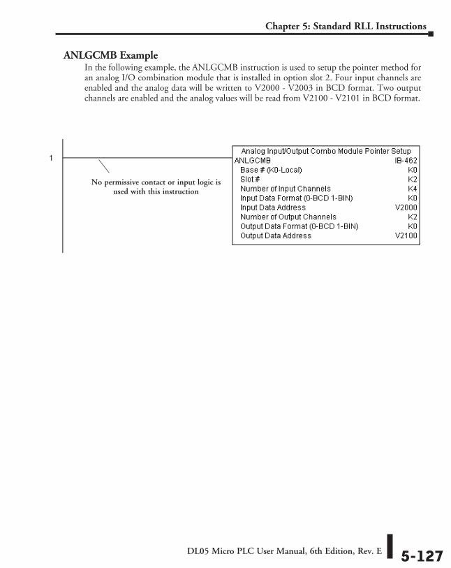
DL05 Micro PLC User Manual, 6th Edition, Rev. E 5-127
Chapter 5: Standard RLL Instructions
ANLGCMB ExampleIn the following example, the ANLGCMB instruction is used to setup the pointer method for an analog I/O combination module that is installed in option slot 2. Four input channels are enabled and the analog data will be written to V2000 - V2003 in BCD format. Two output channels are enabled and the analog values will be read from V2100 - V2101 in BCD format.
No permissive contact or input logic is used with this instruction
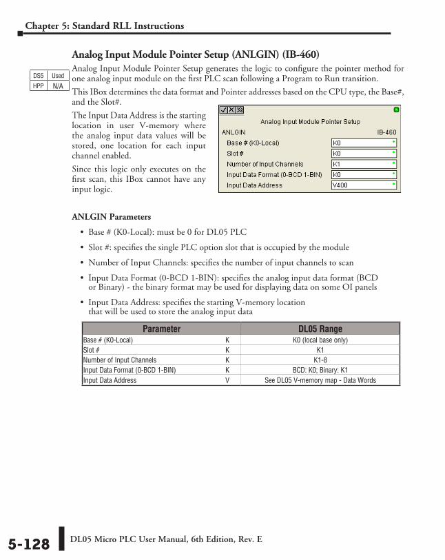
DL05 Micro PLC User Manual, 6th Edition, Rev. E5-128
Chapter 5: Standard RLL Instructions
Analog Input Module Pointer Setup (ANLGIN) (IB-460)Analog Input Module Pointer Setup generates the logic to configure the pointer method for one analog input module on the first PLC scan following a Program to Run transition.
This IBox determines the data format and Pointer addresses based on the CPU type, the Base#, and the Slot#.
The Input Data Address is the starting location in user V-memory where the analog input data values will be stored, one location for each input channel enabled.
Since this logic only executes on the first scan, this IBox cannot have any input logic.
ANLGIN Parameters
• Base # (K0-Local): must be 0 for DL05 PLC
• Slot #: specifies the single PLC option slot that is occupied by the module
• Number of Input Channels: specifies the number of input channels to scan
• Input Data Format (0-BCD 1-BIN): specifies the analog input data format (BCD or Binary) - the binary format may be used for displaying data on some OI panels
• Input Data Address: specifies the starting V-memory location that will be used to store the analog input data
DS5 Used
HPP N/A
Parameter DL05 RangeBase # (K0-Local) ⸠⸠⸠⸠⸠⸠⸠⸠⸠⸠⸠⸠⸠⸠⸠⸠⸠⸠⸠⸠⸠⸠⸠⸠⸠⸠⸠⸠⸠⸠⸠⸠⸠⸠⸠⸠⸠⸠⸠⸠⸠⸠⸠⸠⸠⸠⸠⸠⸠⸠⸠⸠ K K0 (local base only)Slot # ⸠⸠⸠⸠⸠⸠⸠⸠⸠⸠⸠⸠⸠⸠⸠⸠⸠⸠⸠⸠⸠⸠⸠⸠⸠⸠⸠⸠⸠⸠⸠⸠⸠⸠⸠⸠⸠⸠⸠⸠⸠⸠⸠⸠⸠⸠⸠⸠⸠⸠⸠⸠⸠⸠⸠⸠⸠⸠⸠⸠⸠⸠⸠⸠⸠⸠⸠⸠⸠⸠⸠⸠ K K1Number of Input Channels ⸠⸠⸠⸠⸠⸠⸠⸠⸠⸠⸠⸠⸠⸠⸠⸠⸠⸠⸠⸠⸠⸠⸠⸠⸠⸠⸠⸠⸠⸠⸠⸠⸠⸠⸠⸠⸠⸠ K K1-8Input Data Format (0-BCD 1-BIN) ⸠⸠⸠⸠⸠⸠⸠⸠⸠⸠⸠⸠⸠⸠⸠⸠⸠⸠⸠⸠⸠⸠⸠⸠⸠⸠⸠⸠ K BCD: K0; Binary: K1Input Data Address ⸠⸠⸠⸠⸠⸠⸠⸠⸠⸠⸠⸠⸠⸠⸠⸠⸠⸠⸠⸠⸠⸠⸠⸠⸠⸠⸠⸠⸠⸠⸠⸠⸠⸠⸠⸠⸠⸠⸠⸠⸠⸠⸠⸠⸠⸠⸠⸠⸠⸠ V See DL05 V-memory map - Data Words
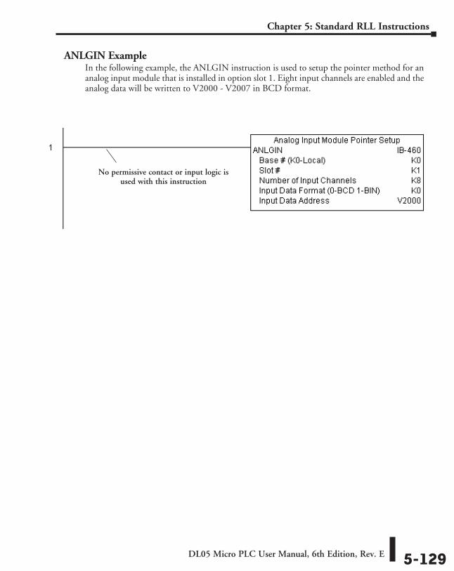
DL05 Micro PLC User Manual, 6th Edition, Rev. E 5-129
Chapter 5: Standard RLL Instructions
ANLGIN ExampleIn the following example, the ANLGIN instruction is used to setup the pointer method for an analog input module that is installed in option slot 1. Eight input channels are enabled and the analog data will be written to V2000 - V2007 in BCD format.
No permissive contact or input logic is used with this instruction
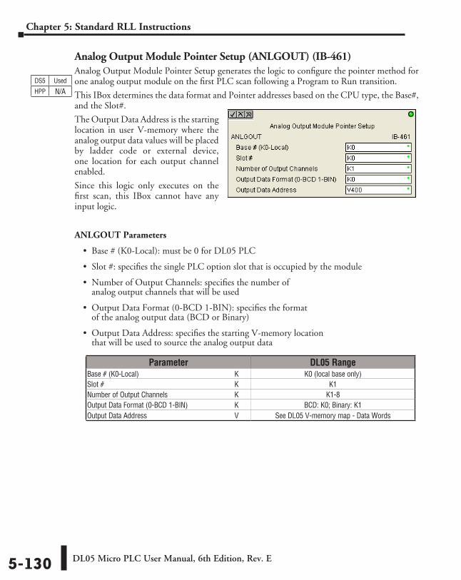
DL05 Micro PLC User Manual, 6th Edition, Rev. E5-130
Chapter 5: Standard RLL Instructions
Analog Output Module Pointer Setup (ANLGOUT) (IB-461)Analog Output Module Pointer Setup generates the logic to configure the pointer method for one analog output module on the first PLC scan following a Program to Run transition.
This IBox determines the data format and Pointer addresses based on the CPU type, the Base#, and the Slot#.
The Output Data Address is the starting location in user V-memory where the analog output data values will be placed by ladder code or external device, one location for each output channel enabled.
Since this logic only executes on the first scan, this IBox cannot have any input logic.
ANLGOUT Parameters
• Base # (K0-Local): must be 0 for DL05 PLC
• Slot #: specifies the single PLC option slot that is occupied by the module
• Number of Output Channels: specifies the number of analog output channels that will be used
• Output Data Format (0-BCD 1-BIN): specifies the format of the analog output data (BCD or Binary)
• Output Data Address: specifies the starting V-memory location that will be used to source the analog output data
DS5 Used
HPP N/A
Parameter DL05 RangeBase # (K0-Local) ⸠⸠⸠⸠⸠⸠⸠⸠⸠⸠⸠⸠⸠⸠⸠⸠⸠⸠⸠⸠⸠⸠⸠⸠⸠⸠⸠⸠⸠⸠⸠⸠⸠⸠⸠⸠⸠⸠⸠⸠⸠⸠⸠⸠⸠⸠⸠⸠⸠⸠⸠⸠ K K0 (local base only)Slot # ⸠⸠⸠⸠⸠⸠⸠⸠⸠⸠⸠⸠⸠⸠⸠⸠⸠⸠⸠⸠⸠⸠⸠⸠⸠⸠⸠⸠⸠⸠⸠⸠⸠⸠⸠⸠⸠⸠⸠⸠⸠⸠⸠⸠⸠⸠⸠⸠⸠⸠⸠⸠⸠⸠⸠⸠⸠⸠⸠⸠⸠⸠⸠⸠⸠⸠⸠⸠⸠⸠⸠⸠ K K1Number of Output Channels ⸠⸠⸠⸠⸠⸠⸠⸠⸠⸠⸠⸠⸠⸠⸠⸠⸠⸠⸠⸠⸠⸠⸠⸠⸠⸠⸠⸠⸠⸠⸠⸠⸠⸠⸠⸠ K K1-8Output Data Format (0-BCD 1-BIN) ⸠⸠⸠⸠⸠⸠⸠⸠⸠⸠⸠⸠⸠⸠⸠⸠⸠⸠⸠⸠⸠⸠⸠⸠⸠ K BCD: K0; Binary: K1 Output Data Address ⸠⸠⸠⸠⸠⸠⸠⸠⸠⸠⸠⸠⸠⸠⸠⸠⸠⸠⸠⸠⸠⸠⸠⸠⸠⸠⸠⸠⸠⸠⸠⸠⸠⸠⸠⸠⸠⸠⸠⸠⸠⸠⸠⸠⸠⸠⸠⸠ V See DL05 V-memory map - Data Words
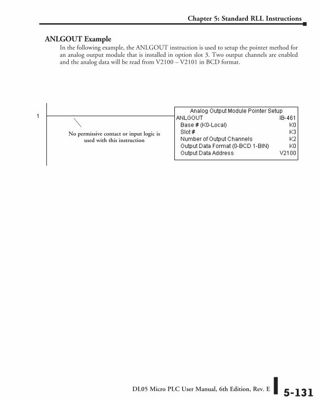
DL05 Micro PLC User Manual, 6th Edition, Rev. E 5-131
Chapter 5: Standard RLL Instructions
ANLGOUT ExampleIn the following example, the ANLGOUT instruction is used to setup the pointer method for an analog output module that is installed in option slot 3. Two output channels are enabled and the analog data will be read from V2100 – V2101 in BCD format.
No permissive contact or input logic is used with this instruction
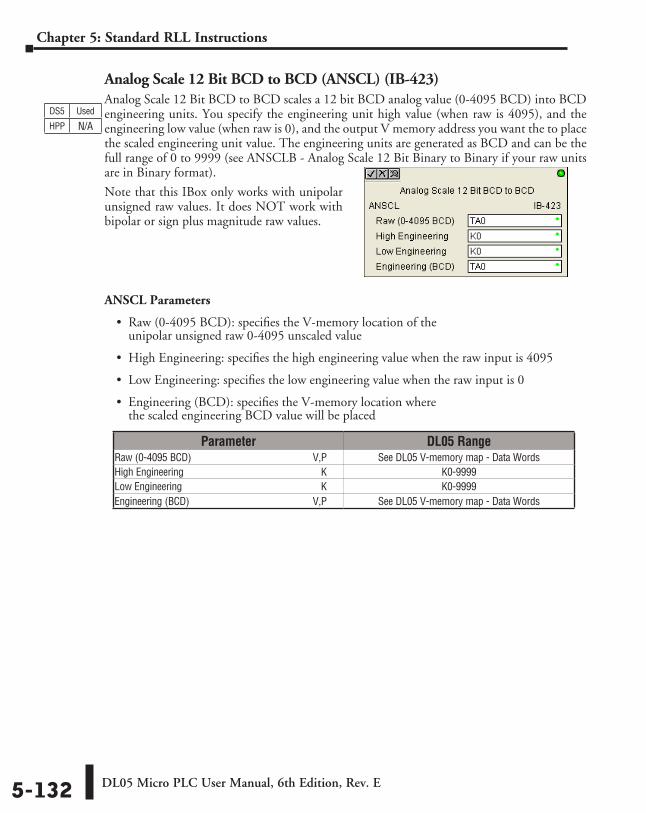
DL05 Micro PLC User Manual, 6th Edition, Rev. E5-132
Chapter 5: Standard RLL Instructions
Analog Scale 12 Bit BCD to BCD (ANSCL) (IB-423)Analog Scale 12 Bit BCD to BCD scales a 12 bit BCD analog value (0-4095 BCD) into BCD engineering units. You specify the engineering unit high value (when raw is 4095), and the engineering low value (when raw is 0), and the output V memory address you want the to place the scaled engineering unit value. The engineering units are generated as BCD and can be the full range of 0 to 9999 (see ANSCLB - Analog Scale 12 Bit Binary to Binary if your raw units are in Binary format).
Note that this IBox only works with unipolar unsigned raw values. It does NOT work with bipolar or sign plus magnitude raw values.
ANSCL Parameters
• Raw (0-4095 BCD): specifies the V-memory location of the unipolar unsigned raw 0-4095 unscaled value
• High Engineering: specifies the high engineering value when the raw input is 4095
• Low Engineering: specifies the low engineering value when the raw input is 0
• Engineering (BCD): specifies the V-memory location where the scaled engineering BCD value will be placed
DS5 Used
HPP N/A
Parameter DL05 RangeRaw (0-4095 BCD) ⸠⸠⸠⸠⸠⸠⸠⸠⸠⸠⸠⸠⸠⸠⸠⸠⸠⸠⸠⸠⸠⸠⸠⸠⸠⸠⸠⸠⸠⸠⸠⸠⸠⸠⸠⸠⸠⸠⸠⸠⸠⸠⸠⸠⸠⸠⸠V,P See DL05 V-memory map - Data WordsHigh Engineering ⸠⸠⸠⸠⸠⸠⸠⸠⸠⸠⸠⸠⸠⸠⸠⸠⸠⸠⸠⸠⸠⸠⸠⸠⸠⸠⸠⸠⸠⸠⸠⸠⸠⸠⸠⸠⸠⸠⸠⸠⸠⸠⸠⸠⸠⸠⸠⸠⸠⸠⸠⸠⸠ K K0-9999Low Engineering ⸠⸠⸠⸠⸠⸠⸠⸠⸠⸠⸠⸠⸠⸠⸠⸠⸠⸠⸠⸠⸠⸠⸠⸠⸠⸠⸠⸠⸠⸠⸠⸠⸠⸠⸠⸠⸠⸠⸠⸠⸠⸠⸠⸠⸠⸠⸠⸠⸠⸠⸠⸠⸠⸠ K K0-9999Engineering (BCD) ⸠⸠⸠⸠⸠⸠⸠⸠⸠⸠⸠⸠⸠⸠⸠⸠⸠⸠⸠⸠⸠⸠⸠⸠⸠⸠⸠⸠⸠⸠⸠⸠⸠⸠⸠⸠⸠⸠⸠⸠⸠⸠⸠⸠⸠⸠⸠⸠⸠V,P See DL05 V-memory map - Data Words
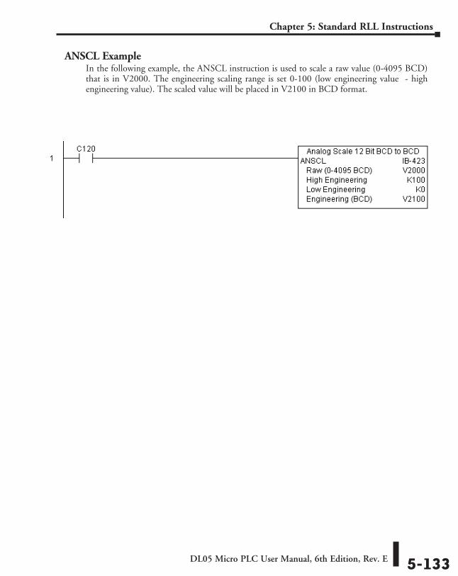
DL05 Micro PLC User Manual, 6th Edition, Rev. E 5-133
Chapter 5: Standard RLL Instructions
ANSCL ExampleIn the following example, the ANSCL instruction is used to scale a raw value (0-4095 BCD) that is in V2000. The engineering scaling range is set 0-100 (low engineering value - high engineering value). The scaled value will be placed in V2100 in BCD format.
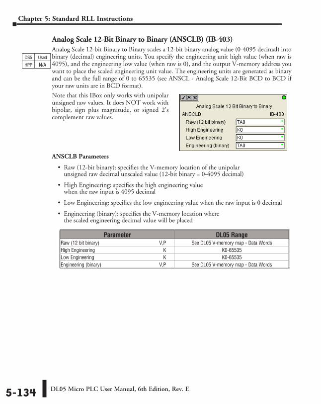
DL05 Micro PLC User Manual, 6th Edition, Rev. E5-134
Chapter 5: Standard RLL Instructions
Analog Scale 12-Bit Binary to Binary (ANSCLB) (IB-403)Analog Scale 12-bit Binary to Binary scales a 12-bit binary analog value (0-4095 decimal) into binary (decimal) engineering units. You specify the engineering unit high value (when raw is 4095), and the engineering low value (when raw is 0), and the output V-memory address you want to place the scaled engineering unit value. The engineering units are generated as binary and can be the full range of 0 to 65535 (see ANSCL - Analog Scale 12-Bit BCD to BCD if your raw units are in BCD format).
Note that this IBox only works with unipolar unsigned raw values. It does NOT work with bipolar, sign plus magnitude, or signed 2’s complement raw values.
ANSCLB Parameters
• Raw (12-bit binary): specifies the V-memory location of the unipolar unsigned raw decimal unscaled value (12-bit binary = 0-4095 decimal)
• High Engineering: specifies the high engineering value when the raw input is 4095 decimal
• Low Engineering: specifies the low engineering value when the raw input is 0 decimal
• Engineering (binary): specifies the V-memory location where the scaled engineering decimal value will be placed
Parameter DL05 RangeRaw (12 bit binary) ⸠⸠⸠⸠⸠⸠⸠⸠⸠⸠⸠⸠⸠⸠⸠⸠⸠⸠⸠⸠⸠⸠⸠⸠⸠⸠⸠⸠⸠⸠⸠⸠⸠⸠⸠⸠⸠⸠⸠⸠⸠⸠⸠⸠⸠⸠⸠V,P See DL05 V-memory map - Data WordsHigh Engineering ⸠⸠⸠⸠⸠⸠⸠⸠⸠⸠⸠⸠⸠⸠⸠⸠⸠⸠⸠⸠⸠⸠⸠⸠⸠⸠⸠⸠⸠⸠⸠⸠⸠⸠⸠⸠⸠⸠⸠⸠⸠⸠⸠⸠⸠⸠⸠⸠⸠⸠⸠⸠⸠ K K0-65535Low Engineering ⸠⸠⸠⸠⸠⸠⸠⸠⸠⸠⸠⸠⸠⸠⸠⸠⸠⸠⸠⸠⸠⸠⸠⸠⸠⸠⸠⸠⸠⸠⸠⸠⸠⸠⸠⸠⸠⸠⸠⸠⸠⸠⸠⸠⸠⸠⸠⸠⸠⸠⸠⸠⸠⸠ K K0-65535Engineering (binary) ⸠⸠⸠⸠⸠⸠⸠⸠⸠⸠⸠⸠⸠⸠⸠⸠⸠⸠⸠⸠⸠⸠⸠⸠⸠⸠⸠⸠⸠⸠⸠⸠⸠⸠⸠⸠⸠⸠⸠⸠⸠⸠⸠⸠⸠⸠V,P See DL05 V-memory map - Data Words
DS5 Used
HPP N/A
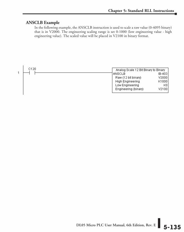
DL05 Micro PLC User Manual, 6th Edition, Rev. E 5-135
Chapter 5: Standard RLL Instructions
ANSCLB ExampleIn the following example, the ANSCLB instruction is used to scale a raw value (0-4095 binary) that is in V2000. The engineering scaling range is set 0-1000 (low engineering value - high engineering value). The scaled value will be placed in V2100 in binary format.
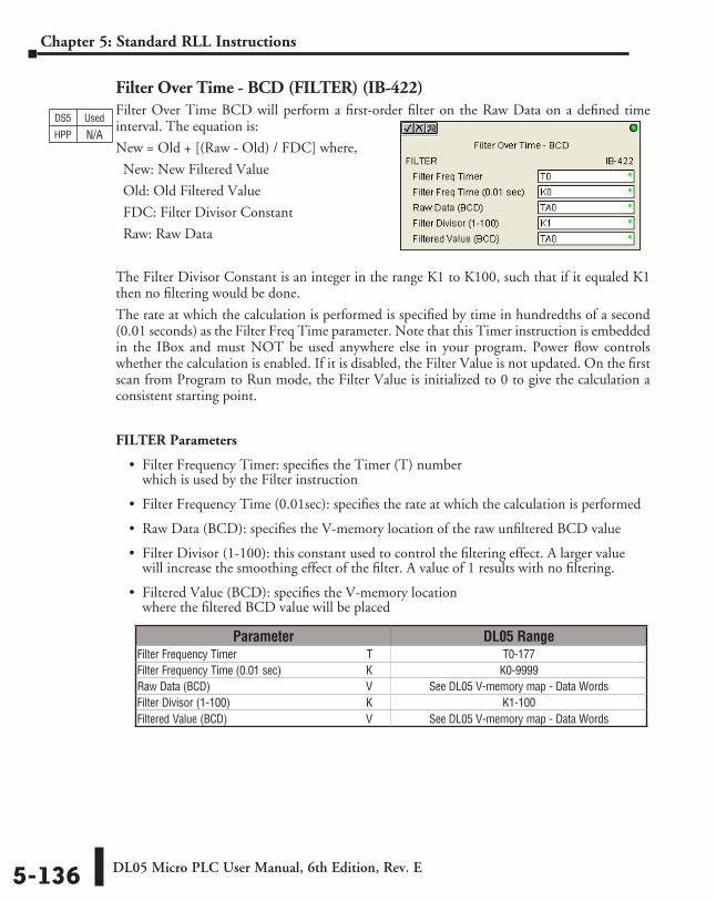
DL05 Micro PLC User Manual, 6th Edition, Rev. E5-136
Chapter 5: Standard RLL Instructions
Filter Over Time - BCD (FILTER) (IB-422)Filter Over Time BCD will perform a first-order filter on the Raw Data on a defined time interval. The equation is:
New = Old + [(Raw - Old) / FDC] where,
New: New Filtered Value
Old: Old Filtered Value
FDC: Filter Divisor Constant
Raw: Raw Data
The Filter Divisor Constant is an integer in the range K1 to K100, such that if it equaled K1 then no filtering would be done.
The rate at which the calculation is performed is specified by time in hundredths of a second (0.01 seconds) as the Filter Freq Time parameter. Note that this Timer instruction is embedded in the IBox and must NOT be used anywhere else in your program. Power flow controls whether the calculation is enabled. If it is disabled, the Filter Value is not updated. On the first scan from Program to Run mode, the Filter Value is initialized to 0 to give the calculation a consistent starting point.
FILTER Parameters
• Filter Frequency Timer: specifies the Timer (T) number which is used by the Filter instruction
• Filter Frequency Time (0.01sec): specifies the rate at which the calculation is performed
• Raw Data (BCD): specifies the V-memory location of the raw unfiltered BCD value
• Filter Divisor (1-100): this constant used to control the filtering effect. A larger value will increase the smoothing effect of the filter. A value of 1 results with no filtering.
• Filtered Value (BCD): specifies the V-memory location where the filtered BCD value will be placed
DS5 Used
HPP N/A
Parameter DL05 RangeFilter Frequency Timer ⸠⸠⸠⸠⸠⸠⸠⸠⸠⸠⸠⸠⸠⸠⸠⸠⸠⸠⸠⸠⸠⸠⸠⸠⸠⸠⸠⸠⸠⸠⸠⸠⸠⸠⸠⸠⸠⸠⸠⸠⸠⸠⸠⸠ T T0-177Filter Frequency Time (0.01 sec) ⸠⸠⸠⸠⸠⸠⸠⸠⸠⸠⸠⸠⸠⸠⸠⸠⸠⸠⸠⸠⸠⸠⸠⸠⸠⸠⸠⸠⸠ K K0-9999Raw Data (BCD) ⸠⸠⸠⸠⸠⸠⸠⸠⸠⸠⸠⸠⸠⸠⸠⸠⸠⸠⸠⸠⸠⸠⸠⸠⸠⸠⸠⸠⸠⸠⸠⸠⸠⸠⸠⸠⸠⸠⸠⸠⸠⸠⸠⸠⸠⸠⸠⸠⸠⸠⸠⸠⸠⸠⸠ V See DL05 V-memory map - Data WordsFilter Divisor (1-100) ⸠⸠⸠⸠⸠⸠⸠⸠⸠⸠⸠⸠⸠⸠⸠⸠⸠⸠⸠⸠⸠⸠⸠⸠⸠⸠⸠⸠⸠⸠⸠⸠⸠⸠⸠⸠⸠⸠⸠⸠⸠⸠⸠⸠⸠⸠⸠⸠ K K1-100Filtered Value (BCD) ⸠⸠⸠⸠⸠⸠⸠⸠⸠⸠⸠⸠⸠⸠⸠⸠⸠⸠⸠⸠⸠⸠⸠⸠⸠⸠⸠⸠⸠⸠⸠⸠⸠⸠⸠⸠⸠⸠⸠⸠⸠⸠⸠⸠⸠⸠⸠⸠⸠ V See DL05 V-memory map - Data Words
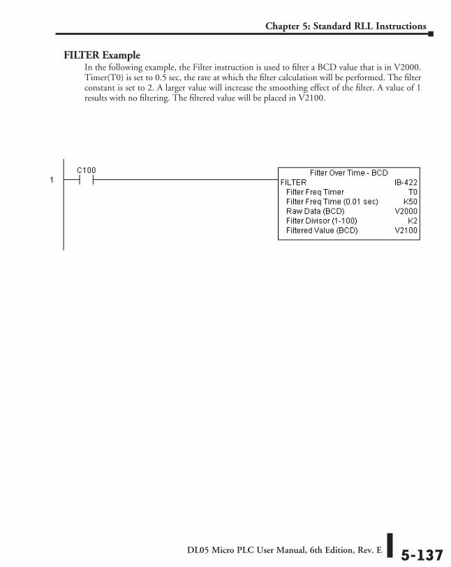
DL05 Micro PLC User Manual, 6th Edition, Rev. E 5-137
Chapter 5: Standard RLL Instructions
FILTER ExampleIn the following example, the Filter instruction is used to filter a BCD value that is in V2000. Timer(T0) is set to 0.5 sec, the rate at which the filter calculation will be performed. The filter constant is set to 2. A larger value will increase the smoothing effect of the filter. A value of 1 results with no filtering. The filtered value will be placed in V2100.
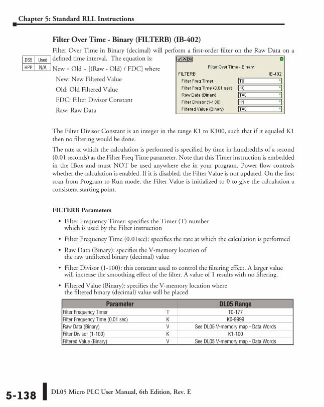
DL05 Micro PLC User Manual, 6th Edition, Rev. E5-138
Chapter 5: Standard RLL Instructions
Filter Over Time - Binary (FILTERB) (IB-402)Filter Over Time in Binary (decimal) will perform a first-order filter on the Raw Data on a defined time interval. The equation is:
New = Old + [(Raw - Old) / FDC] where
New: New Filtered Value
Old: Old Filtered Value
FDC: Filter Divisor Constant
Raw: Raw Data
The Filter Divisor Constant is an integer in the range K1 to K100, such that if it equaled K1 then no filtering would be done.
The rate at which the calculation is performed is specified by time in hundredths of a second (0.01 seconds) as the Filter Freq Time parameter. Note that this Timer instruction is embedded in the IBox and must NOT be used anywhere else in your program. Power flow controls whether the calculation is enabled. If it is disabled, the Filter Value is not updated. On the first scan from Program to Run mode, the Filter Value is initialized to 0 to give the calculation a consistent starting point.
FILTERB Parameters
• Filter Frequency Timer: specifies the Timer (T) number which is used by the Filter instruction
• Filter Frequency Time (0.01sec): specifies the rate at which the calculation is performed
• Raw Data (Binary): specifies the V-memory location of the raw unfiltered binary (decimal) value
• Filter Divisor (1-100): this constant used to control the filtering effect. A larger value will increase the smoothing effect of the filter. A value of 1 results with no filtering.
• Filtered Value (Binary): specifies the V-memory location where the filtered binary (decimal) value will be placed
DS5 Used
HPP N/A
Parameter DL05 RangeFilter Frequency Timer ⸠⸠⸠⸠⸠⸠⸠⸠⸠⸠⸠⸠⸠⸠⸠⸠⸠⸠⸠⸠⸠⸠⸠⸠⸠⸠⸠⸠⸠⸠⸠⸠⸠⸠⸠⸠⸠⸠⸠⸠⸠⸠⸠⸠ T T0-177Filter Frequency Time (0.01 sec) ⸠⸠⸠⸠⸠⸠⸠⸠⸠⸠⸠⸠⸠⸠⸠⸠⸠⸠⸠⸠⸠⸠⸠⸠⸠⸠⸠⸠⸠ K K0-9999Raw Data (Binary) ⸠⸠⸠⸠⸠⸠⸠⸠⸠⸠⸠⸠⸠⸠⸠⸠⸠⸠⸠⸠⸠⸠⸠⸠⸠⸠⸠⸠⸠⸠⸠⸠⸠⸠⸠⸠⸠⸠⸠⸠⸠⸠⸠⸠⸠⸠⸠⸠⸠⸠⸠⸠ V See DL05 V-memory map - Data WordsFilter Divisor (1-100) ⸠⸠⸠⸠⸠⸠⸠⸠⸠⸠⸠⸠⸠⸠⸠⸠⸠⸠⸠⸠⸠⸠⸠⸠⸠⸠⸠⸠⸠⸠⸠⸠⸠⸠⸠⸠⸠⸠⸠⸠⸠⸠⸠⸠⸠⸠⸠⸠ K K1-100Filtered Value (Binary) ⸠⸠⸠⸠⸠⸠⸠⸠⸠⸠⸠⸠⸠⸠⸠⸠⸠⸠⸠⸠⸠⸠⸠⸠⸠⸠⸠⸠⸠⸠⸠⸠⸠⸠⸠⸠⸠⸠⸠⸠⸠⸠⸠⸠⸠ V See DL05 V-memory map - Data Words
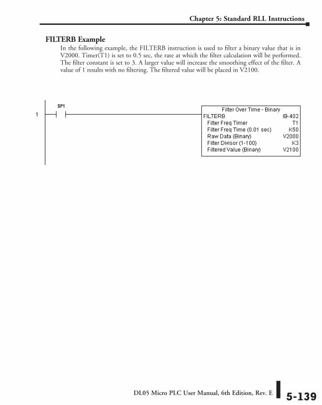
DL05 Micro PLC User Manual, 6th Edition, Rev. E 5-139
Chapter 5: Standard RLL Instructions
FILTERB ExampleIn the following example, the FILTERB instruction is used to filter a binary value that is in V2000. Timer(T1) is set to 0.5 sec, the rate at which the filter calculation will be performed. The filter constant is set to 3. A larger value will increase the smoothing effect of the filter. A value of 1 results with no filtering. The filtered value will be placed in V2100.
SP1
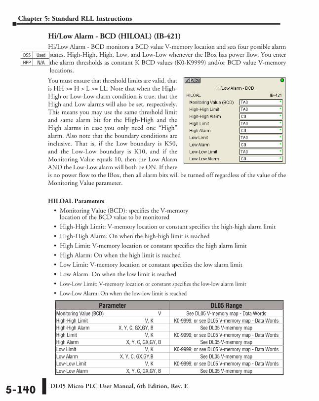
DL05 Micro PLC User Manual, 6th Edition, Rev. E5-140
Chapter 5: Standard RLL Instructions
Hi/Low Alarm - BCD (HILOAL) (IB-421)Hi/Low Alarm - BCD monitors a BCD value V-memory location and sets four possible alarm states, High-High, High, Low, and Low-Low whenever the IBox has power flow. You enter the alarm thresholds as constant K BCD values (K0-K9999) and/or BCD value V-memory locations.
You must ensure that threshold limits are valid, that is HH >= H > L >= LL. Note that when the High-High or Low-Low alarm condition is true, that the High and Low alarms will also be set, respectively. This means you may use the same threshold limit and same alarm bit for the High-High and the High alarms in case you only need one “High” alarm. Also note that the boundary conditions are inclusive. That is, if the Low boundary is K50, and the Low-Low boundary is K10, and if the Monitoring Value equals 10, then the Low Alarm AND the Low-Low alarm will both be ON. If there is no power flow to the IBox, then all alarm bits will be turned off regardless of the value of the Monitoring Value parameter.
HILOAL Parameters
• Monitoring Value (BCD): specifies the V-memory location of the BCD value to be monitored
• High-High Limit: V-memory location or constant specifies the high-high alarm limit
• High-High Alarm: On when the high-high limit is reached
• High Limit: V-memory location or constant specifies the high alarm limit
• High Alarm: On when the high limit is reached
• Low Limit: V-memory location or constant specifies the low alarm limit
• Low Alarm: On when the low limit is reached
• Low-Low Limit: V-memory location or constant specifies the low-low alarm limit
• Low-Low Alarm: On when the low-low limit is reached
DS5 Used
HPP N/A
Parameter DL05 RangeMonitoring Value (BCD) ⸠⸠⸠⸠⸠⸠⸠⸠⸠⸠⸠⸠⸠⸠⸠⸠⸠⸠⸠⸠⸠⸠⸠⸠⸠⸠⸠⸠⸠⸠⸠⸠⸠⸠⸠⸠⸠⸠⸠⸠⸠ V See DL05 V-memory map - Data WordsHigh-High Limit ⸠⸠⸠⸠⸠⸠⸠⸠⸠⸠⸠⸠⸠⸠⸠⸠⸠⸠⸠⸠⸠⸠⸠⸠⸠⸠⸠⸠⸠⸠⸠⸠⸠⸠⸠⸠⸠⸠⸠⸠⸠⸠⸠⸠⸠ V, K K0-9999; or see DL05 V-memory map - Data Words High-High Alarm ⸠⸠⸠⸠⸠⸠⸠⸠⸠⸠⸠⸠⸠⸠⸠⸠⸠⸠⸠⸠⸠ X, Y, C, GX,GY, B See DL05 V-memory mapHigh Limit ⸠⸠⸠⸠⸠⸠⸠⸠⸠⸠⸠⸠⸠⸠⸠⸠⸠⸠⸠⸠⸠⸠⸠⸠⸠⸠⸠⸠⸠⸠⸠⸠⸠⸠⸠⸠⸠⸠⸠⸠⸠⸠⸠⸠⸠⸠⸠⸠⸠⸠⸠⸠⸠⸠ V, K K0-9999; or see DL05 V-memory map - Data WordsHigh Alarm ⸠⸠⸠⸠⸠⸠⸠⸠⸠⸠⸠⸠⸠⸠⸠⸠⸠⸠⸠⸠⸠⸠⸠⸠⸠⸠⸠⸠⸠⸠⸠⸠⸠⸠⸠⸠⸠ X, Y, C, GX,GY, B See DL05 V-memory mapLow Limit ⸠⸠⸠⸠⸠⸠⸠⸠⸠⸠⸠⸠⸠⸠⸠⸠⸠⸠⸠⸠⸠⸠⸠⸠⸠⸠⸠⸠⸠⸠⸠⸠⸠⸠⸠⸠⸠⸠⸠⸠⸠⸠⸠⸠⸠⸠⸠⸠⸠⸠⸠⸠⸠⸠ V, K K0-9999; or see DL05 V-memory map - Data Words Low Alarm ⸠⸠⸠⸠⸠⸠⸠⸠⸠⸠⸠⸠⸠⸠⸠⸠⸠⸠⸠⸠⸠⸠⸠⸠⸠⸠⸠⸠⸠⸠⸠⸠ X, Y, C, GX,GY,B See DL05 V-memory mapLow-Low Limit ⸠⸠⸠⸠⸠⸠⸠⸠⸠⸠⸠⸠⸠⸠⸠⸠⸠⸠⸠⸠⸠⸠⸠⸠⸠⸠⸠⸠⸠⸠⸠⸠⸠⸠⸠⸠⸠⸠⸠⸠⸠⸠⸠⸠⸠⸠ V, K K0-9999; or see DL05 V-memory map - Data WordsLow-Low Alarm⸠⸠⸠⸠⸠⸠⸠⸠⸠⸠⸠⸠⸠⸠⸠⸠⸠⸠⸠⸠⸠⸠⸠⸠⸠⸠⸠⸠⸠⸠⸠X, Y, C, GX,GY, B See DL05 V-memory map
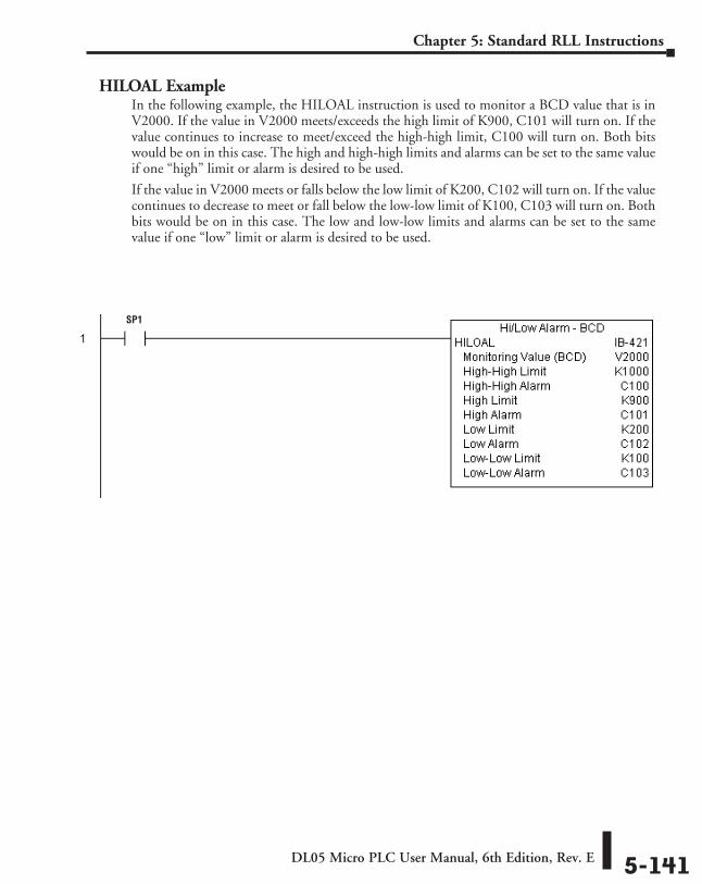
DL05 Micro PLC User Manual, 6th Edition, Rev. E 5-141
Chapter 5: Standard RLL Instructions
HILOAL ExampleIn the following example, the HILOAL instruction is used to monitor a BCD value that is in V2000. If the value in V2000 meets/exceeds the high limit of K900, C101 will turn on. If the value continues to increase to meet/exceed the high-high limit, C100 will turn on. Both bits would be on in this case. The high and high-high limits and alarms can be set to the same value if one “high” limit or alarm is desired to be used.
If the value in V2000 meets or falls below the low limit of K200, C102 will turn on. If the value continues to decrease to meet or fall below the low-low limit of K100, C103 will turn on. Both bits would be on in this case. The low and low-low limits and alarms can be set to the same value if one “low” limit or alarm is desired to be used.
SP1
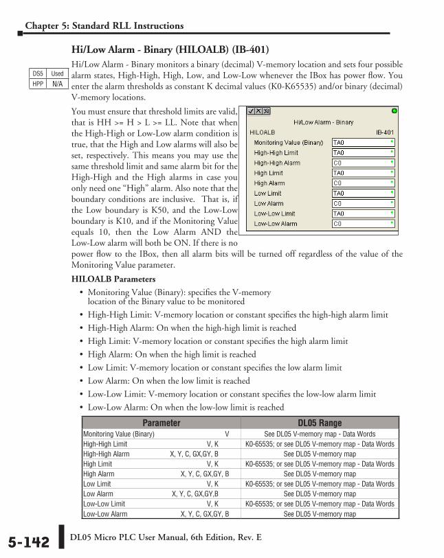
DL05 Micro PLC User Manual, 6th Edition, Rev. E5-142
Chapter 5: Standard RLL Instructions
Hi/Low Alarm - Binary (HILOALB) (IB-401)Hi/Low Alarm - Binary monitors a binary (decimal) V-memory location and sets four possible alarm states, High-High, High, Low, and Low-Low whenever the IBox has power flow. You enter the alarm thresholds as constant K decimal values (K0-K65535) and/or binary (decimal) V-memory locations.
You must ensure that threshold limits are valid, that is HH >= H > L >= LL. Note that when the High-High or Low-Low alarm condition is true, that the High and Low alarms will also be set, respectively. This means you may use the same threshold limit and same alarm bit for the High-High and the High alarms in case you only need one “High” alarm. Also note that the boundary conditions are inclusive. That is, if the Low boundary is K50, and the Low-Low boundary is K10, and if the Monitoring Value equals 10, then the Low Alarm AND the Low-Low alarm will both be ON. If there is no power flow to the IBox, then all alarm bits will be turned off regardless of the value of the Monitoring Value parameter.
HILOALB Parameters
• Monitoring Value (Binary): specifies the V-memory location of the Binary value to be monitored
• High-High Limit: V-memory location or constant specifies the high-high alarm limit
• High-High Alarm: On when the high-high limit is reached
• High Limit: V-memory location or constant specifies the high alarm limit
• High Alarm: On when the high limit is reached
• Low Limit: V-memory location or constant specifies the low alarm limit
• Low Alarm: On when the low limit is reached
• Low-Low Limit: V-memory location or constant specifies the low-low alarm limit
• Low-Low Alarm: On when the low-low limit is reached
Parameter DL05 RangeMonitoring Value (Binary) ⸠⸠⸠⸠⸠⸠⸠⸠⸠⸠⸠⸠⸠⸠⸠⸠⸠⸠⸠⸠⸠⸠⸠⸠⸠⸠⸠⸠⸠⸠⸠⸠⸠⸠⸠⸠⸠⸠ V See DL05 V-memory map - Data WordsHigh-High Limit ⸠⸠⸠⸠⸠⸠⸠⸠⸠⸠⸠⸠⸠⸠⸠⸠⸠⸠⸠⸠⸠⸠⸠⸠⸠⸠⸠⸠⸠⸠⸠⸠⸠⸠⸠⸠⸠⸠⸠⸠⸠⸠⸠⸠⸠ V, K K0-65535; or see DL05 V-memory map - Data Words High-High Alarm ⸠⸠⸠⸠⸠⸠⸠⸠⸠⸠⸠⸠⸠⸠⸠⸠⸠⸠⸠⸠⸠ X, Y, C, GX,GY, B See DL05 V-memory mapHigh Limit ⸠⸠⸠⸠⸠⸠⸠⸠⸠⸠⸠⸠⸠⸠⸠⸠⸠⸠⸠⸠⸠⸠⸠⸠⸠⸠⸠⸠⸠⸠⸠⸠⸠⸠⸠⸠⸠⸠⸠⸠⸠⸠⸠⸠⸠⸠⸠⸠⸠⸠⸠⸠⸠⸠ V, K K0-65535; or see DL05 V-memory map - Data WordsHigh Alarm ⸠⸠⸠⸠⸠⸠⸠⸠⸠⸠⸠⸠⸠⸠⸠⸠⸠⸠⸠⸠⸠⸠⸠⸠⸠⸠⸠⸠⸠⸠⸠⸠⸠⸠⸠⸠⸠ X, Y, C, GX,GY, B See DL05 V-memory mapLow Limit ⸠⸠⸠⸠⸠⸠⸠⸠⸠⸠⸠⸠⸠⸠⸠⸠⸠⸠⸠⸠⸠⸠⸠⸠⸠⸠⸠⸠⸠⸠⸠⸠⸠⸠⸠⸠⸠⸠⸠⸠⸠⸠⸠⸠⸠⸠⸠⸠⸠⸠⸠⸠⸠⸠ V, K K0-65535; or see DL05 V-memory map - Data Words Low Alarm ⸠⸠⸠⸠⸠⸠⸠⸠⸠⸠⸠⸠⸠⸠⸠⸠⸠⸠⸠⸠⸠⸠⸠⸠⸠⸠⸠⸠⸠⸠⸠⸠ X, Y, C, GX,GY,B See DL05 V-memory mapLow-Low Limit ⸠⸠⸠⸠⸠⸠⸠⸠⸠⸠⸠⸠⸠⸠⸠⸠⸠⸠⸠⸠⸠⸠⸠⸠⸠⸠⸠⸠⸠⸠⸠⸠⸠⸠⸠⸠⸠⸠⸠⸠⸠⸠⸠⸠⸠⸠ V, K K0-65535; or see DL05 V-memory map - Data WordsLow-Low Alarm⸠⸠⸠⸠⸠⸠⸠⸠⸠⸠⸠⸠⸠⸠⸠⸠⸠⸠⸠⸠⸠⸠⸠⸠⸠⸠⸠⸠⸠⸠⸠X, Y, C, GX,GY, B See DL05 V-memory map
DS5 Used
HPP N/A
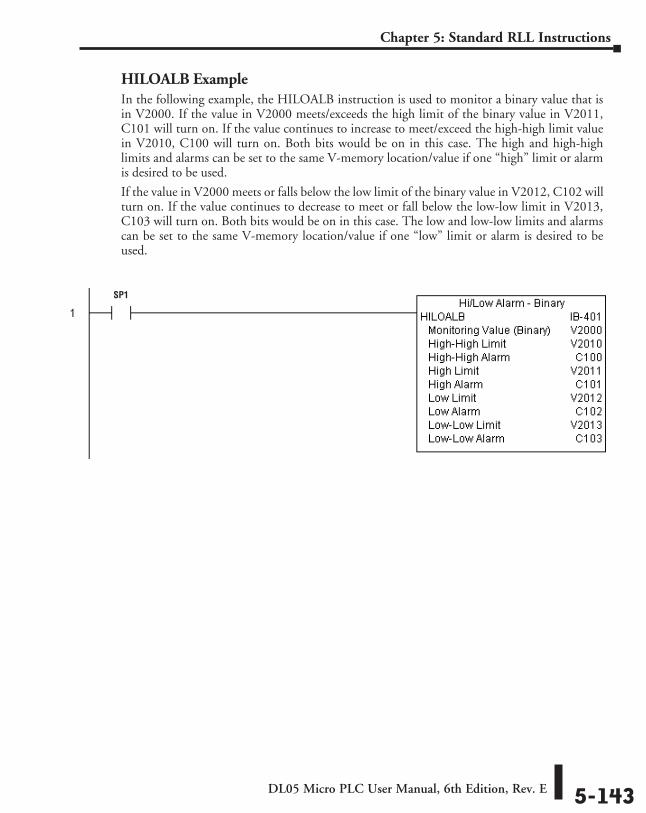
DL05 Micro PLC User Manual, 6th Edition, Rev. E 5-143
Chapter 5: Standard RLL Instructions
HILOALB ExampleIn the following example, the HILOALB instruction is used to monitor a binary value that is in V2000. If the value in V2000 meets/exceeds the high limit of the binary value in V2011, C101 will turn on. If the value continues to increase to meet/exceed the high-high limit value in V2010, C100 will turn on. Both bits would be on in this case. The high and high-high limits and alarms can be set to the same V-memory location/value if one “high” limit or alarm is desired to be used.
If the value in V2000 meets or falls below the low limit of the binary value in V2012, C102 will turn on. If the value continues to decrease to meet or fall below the low-low limit in V2013, C103 will turn on. Both bits would be on in this case. The low and low-low limits and alarms can be set to the same V-memory location/value if one “low” limit or alarm is desired to be used.
SP1
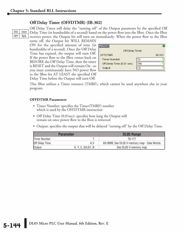
DL05 Micro PLC User Manual, 6th Edition, Rev. E5-144
Chapter 5: Standard RLL Instructions
Off Delay Timer (OFFDTMR) (IB-302)Off Delay Timer will delay the “turning off” of the Output parameter by the specified Off Delay Time (in hundredths of a second) based on the power flow into the IBox. Once the IBox receives power, the Output bit will turn on immediately. When the power flow to the IBox turns off, the Output bit WILL REMAIN ON for the specified amount of time (in hundredths of a second). Once the Off Delay Time has expired, the output will turn Off. If the power flow to the IBox comes back on BEFORE the Off Delay Time, then the timer is RESET and the Output will remain On - so you must continuously have NO power flow to the IBox for AT LEAST the specified Off Delay Time before the Output will turn Off.
This IBox utilizes a Timer resource (TMRF), which cannot be used anywhere else in your program.
OFFDTMR Parameters
• Timer Number: specifies the Timer(TMRF) number which is used by the OFFDTMR instruction
• Off Delay Time (0.01sec): specifies how long the Output will remain on once power flow to the Ibox is removed
• Output: specifies the output that will be delayed “turning off” by the Off Delay Time.
Parameter DL05 RangeTimer Number ⸠⸠⸠⸠⸠⸠⸠⸠⸠⸠⸠⸠⸠⸠⸠⸠⸠⸠⸠⸠⸠⸠⸠⸠⸠⸠⸠⸠⸠⸠⸠⸠⸠⸠⸠⸠⸠⸠⸠⸠⸠⸠⸠⸠⸠⸠⸠⸠⸠⸠⸠⸠⸠⸠⸠⸠⸠ T T0-177Off Delay Time ⸠⸠⸠⸠⸠⸠⸠⸠⸠⸠⸠⸠⸠⸠⸠⸠⸠⸠⸠⸠⸠⸠⸠⸠⸠⸠⸠⸠⸠⸠⸠⸠⸠⸠⸠⸠⸠⸠⸠⸠⸠⸠⸠⸠⸠⸠⸠⸠⸠⸠⸠⸠⸠⸠K,V K0-9999; See DL05 V-memory map - Data WordsOutput⸠⸠⸠⸠⸠⸠⸠⸠⸠⸠⸠⸠⸠⸠⸠⸠⸠⸠⸠⸠⸠⸠⸠⸠⸠⸠⸠⸠⸠⸠⸠⸠⸠⸠⸠⸠⸠⸠⸠⸠⸠⸠⸠⸠⸠⸠X, Y, C, GX,GY, B See DL05 V-memory map
DS5 Used
HPP N/A
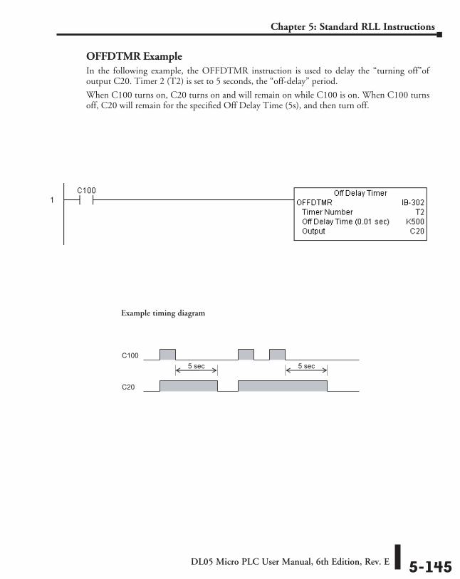
DL05 Micro PLC User Manual, 6th Edition, Rev. E 5-145
Chapter 5: Standard RLL Instructions
OFFDTMR ExampleIn the following example, the OFFDTMR instruction is used to delay the “turning off”of output C20. Timer 2 (T2) is set to 5 seconds, the “off-delay” period.
When C100 turns on, C20 turns on and will remain on while C100 is on. When C100 turns off, C20 will remain for the specified Off Delay Time (5s), and then turn off.
C100
C20
5 sec 5 sec
Example timing diagram
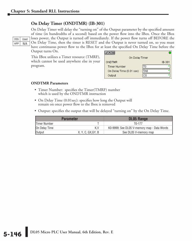
DL05 Micro PLC User Manual, 6th Edition, Rev. E5-146
Chapter 5: Standard RLL Instructions
On Delay Timer (ONDTMR) (IB-301)On Delay Timer will delay the “turning on” of the Output parameter by the specified amount of time (in hundredths of a second) based on the power flow into the IBox. Once the IBox loses power, the Output is turned off immediately. If the power flow turns off BEFORE the On Delay Time, then the timer is RESET and the Output is never turned on, so you must have continuous power flow to the IBox for at least the specified On Delay Time before the Output turns On.
This IBox utilizes a Timer resource (TMRF), which cannot be used anywhere else in your program.
ONDTMR Parameters
• Timer Number: specifies the Timer(TMRF) number which is used by the ONDTMR instruction
• On Delay Time (0.01sec): specifies how long the Output will remain on once power flow to the Ibox is removed
• Output: specifies the output that will be delayed “turning on” by the On Delay Time.
Parameter DL05 RangeTimer Number ⸠⸠⸠⸠⸠⸠⸠⸠⸠⸠⸠⸠⸠⸠⸠⸠⸠⸠⸠⸠⸠⸠⸠⸠⸠⸠⸠⸠⸠⸠⸠⸠⸠⸠⸠⸠⸠⸠⸠⸠⸠⸠⸠⸠⸠⸠⸠⸠⸠⸠⸠⸠⸠⸠⸠⸠⸠ T T0-177On Delay Time ⸠⸠⸠⸠⸠⸠⸠⸠⸠⸠⸠⸠⸠⸠⸠⸠⸠⸠⸠⸠⸠⸠⸠⸠⸠⸠⸠⸠⸠⸠⸠⸠⸠⸠⸠⸠⸠⸠⸠⸠⸠⸠⸠⸠⸠⸠⸠⸠⸠⸠⸠⸠⸠⸠⸠K,V K0-9999; See DL05 V-memory map - Data WordsOutput⸠⸠⸠⸠⸠⸠⸠⸠⸠⸠⸠⸠⸠⸠⸠⸠⸠⸠⸠⸠⸠⸠⸠⸠⸠⸠⸠⸠⸠⸠⸠⸠⸠⸠⸠⸠⸠⸠⸠⸠⸠⸠⸠⸠⸠⸠X, Y, C, GX,GY, B See DL05 V-memory map
DS5 Used
HPP N/A
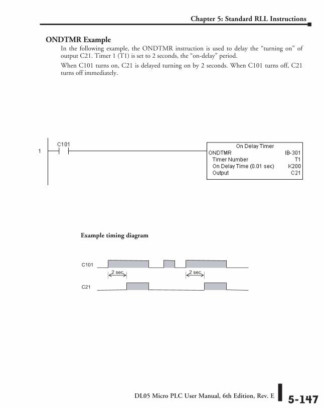
DL05 Micro PLC User Manual, 6th Edition, Rev. E 5-147
Chapter 5: Standard RLL Instructions
ONDTMR ExampleIn the following example, the ONDTMR instruction is used to delay the “turning on” of output C21. Timer 1 (T1) is set to 2 seconds, the “on-delay” period.
When C101 turns on, C21 is delayed turning on by 2 seconds. When C101 turns off, C21 turns off immediately.
C101
C21
2 sec 2 sec
Example timing diagram
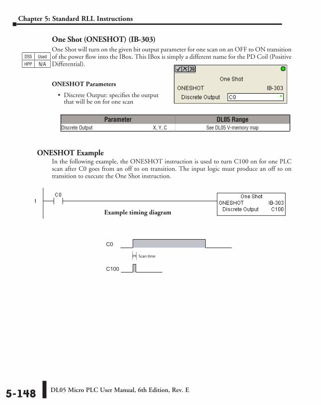
DL05 Micro PLC User Manual, 6th Edition, Rev. E5-148
Chapter 5: Standard RLL Instructions
One Shot (ONESHOT) (IB-303)One Shot will turn on the given bit output parameter for one scan on an OFF to ON transition of the power flow into the IBox. This IBox is simply a different name for the PD Coil (Positive Differential).
ONESHOT Parameters
• Discrete Output: specifies the output that will be on for one scan
ONESHOT ExampleIn the following example, the ONESHOT instruction is used to turn C100 on for one PLC scan after C0 goes from an off to on transition. The input logic must produce an off to on transition to execute the One Shot instruction.
Parameter DL05 RangeDiscrete Output ⸠⸠⸠⸠⸠⸠⸠⸠⸠⸠⸠⸠⸠⸠⸠⸠⸠⸠⸠⸠⸠⸠⸠⸠⸠⸠⸠⸠⸠⸠⸠⸠⸠⸠⸠⸠⸠⸠⸠⸠⸠⸠⸠⸠⸠⸠⸠⸠ X, Y, C See DL05 V-memory map
DS5 Used
HPP N/A
C0
C100
Scan time
Example timing diagram
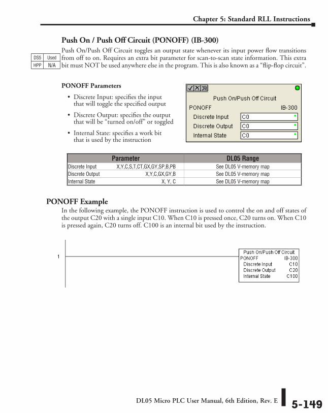
DL05 Micro PLC User Manual, 6th Edition, Rev. E 5-149
Chapter 5: Standard RLL Instructions
Push On / Push Off Circuit (PONOFF) (IB-300)Push On/Push Off Circuit toggles an output state whenever its input power flow transitions from off to on. Requires an extra bit parameter for scan-to-scan state information. This extra bit must NOT be used anywhere else in the program. This is also known as a “flip-flop circuit”.
PONOFF Parameters
• Discrete Input: specifies the input that will toggle the specified output
• Discrete Output: specifies the output that will be “turned on/off” or toggled
• Internal State: specifies a work bit that is used by the instruction
PONOFF ExampleIn the following example, the PONOFF instruction is used to control the on and off states of the output C20 with a single input C10. When C10 is pressed once, C20 turns on. When C10 is pressed again, C20 turns off. C100 is an internal bit used by the instruction.
Parameter DL05 RangeDiscrete Input ⸠⸠⸠⸠⸠⸠⸠⸠⸠⸠⸠⸠ X,Y,C,S,T,CT,GX,GY,SP,B,PB See DL05 V-memory map Discrete Output ⸠⸠⸠⸠⸠⸠⸠⸠⸠⸠⸠⸠⸠⸠⸠⸠⸠⸠⸠⸠⸠⸠⸠⸠⸠⸠⸠⸠⸠⸠⸠⸠⸠⸠ X,Y,C,GX,GY,B See DL05 V-memory mapInternal State ⸠⸠⸠⸠⸠⸠⸠⸠⸠⸠⸠⸠⸠⸠⸠⸠⸠⸠⸠⸠⸠⸠⸠⸠⸠⸠⸠⸠⸠⸠⸠⸠⸠⸠⸠⸠⸠⸠⸠⸠⸠⸠⸠⸠⸠⸠⸠⸠⸠⸠⸠⸠ X, Y, C See DL05 V-memory map
DS5 Used
HPP N/A
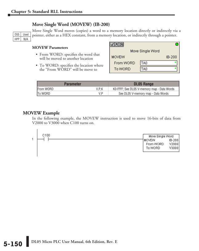
DL05 Micro PLC User Manual, 6th Edition, Rev. E5-150
Chapter 5: Standard RLL Instructions
Move Single Word (MOVEW) (IB-200)Move Single Word moves (copies) a word to a memory location directly or indirectly via a pointer, either as a HEX constant, from a memory location, or indirectly through a pointer.
MOVEW Parameters
• From WORD: specifies the word that will be moved to another location
• To WORD: specifies the location where the “From WORD” will be move to
MOVEW ExampleIn the following example, the MOVEW instruction is used to move 16-bits of data from V2000 to V3000 when C100 turns on.
Parameter DL05 RangeFrom WORD ⸠⸠⸠⸠⸠⸠⸠⸠⸠⸠⸠⸠⸠⸠⸠⸠⸠⸠⸠⸠⸠⸠⸠⸠⸠⸠⸠⸠⸠⸠⸠⸠⸠⸠⸠⸠⸠⸠⸠⸠⸠⸠⸠⸠⸠⸠⸠⸠⸠⸠⸠⸠⸠⸠V,P,K K0-FFFF; See DL05 V-memory map - Data WordsTo WORD ⸠⸠⸠⸠⸠⸠⸠⸠⸠⸠⸠⸠⸠⸠⸠⸠⸠⸠⸠⸠⸠⸠⸠⸠⸠⸠⸠⸠⸠⸠⸠⸠⸠⸠⸠⸠⸠⸠⸠⸠⸠⸠⸠⸠⸠⸠⸠⸠⸠⸠⸠⸠⸠⸠⸠⸠⸠⸠⸠⸠⸠⸠⸠V,P See DL05 V-memory map - Data Words
DS5 Used
HPP N/A
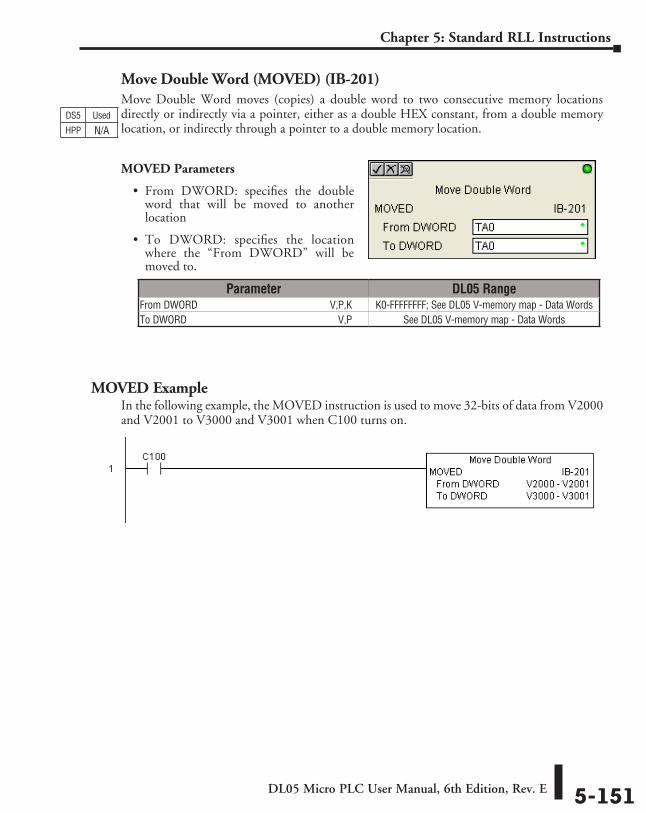
DL05 Micro PLC User Manual, 6th Edition, Rev. E 5-151
Chapter 5: Standard RLL Instructions
Move Double Word (MOVED) (IB-201)Move Double Word moves (copies) a double word to two consecutive memory locations directly or indirectly via a pointer, either as a double HEX constant, from a double memory location, or indirectly through a pointer to a double memory location.
MOVED Parameters
• From DWORD: specifies the double word that will be moved to another location
• To DWORD: specifies the location where the “From DWORD” will be moved to.
MOVED ExampleIn the following example, the MOVED instruction is used to move 32-bits of data from V2000 and V2001 to V3000 and V3001 when C100 turns on.
Parameter DL05 RangeFrom DWORD ⸠⸠⸠⸠⸠⸠⸠⸠⸠⸠⸠⸠⸠⸠⸠⸠⸠⸠⸠⸠⸠⸠⸠⸠⸠⸠⸠⸠⸠⸠⸠⸠⸠⸠⸠⸠⸠⸠⸠⸠⸠⸠⸠⸠⸠⸠⸠⸠⸠⸠⸠V,P,K K0-FFFFFFFF; See DL05 V-memory map - Data WordsTo DWORD ⸠⸠⸠⸠⸠⸠⸠⸠⸠⸠⸠⸠⸠⸠⸠⸠⸠⸠⸠⸠⸠⸠⸠⸠⸠⸠⸠⸠⸠⸠⸠⸠⸠⸠⸠⸠⸠⸠⸠⸠⸠⸠⸠⸠⸠⸠⸠⸠⸠⸠⸠⸠⸠⸠⸠⸠⸠⸠⸠⸠⸠V,P See DL05 V-memory map - Data Words
DS5 Used
HPP N/A
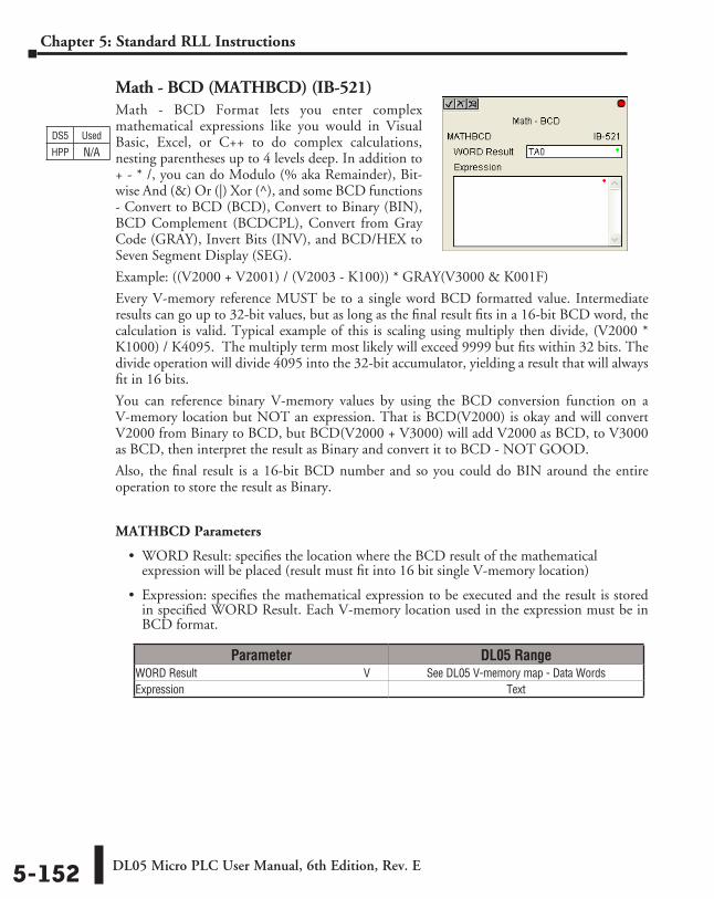
DL05 Micro PLC User Manual, 6th Edition, Rev. E5-152
Chapter 5: Standard RLL Instructions
Math - BCD (MATHBCD) (IB-521)Math - BCD Format lets you enter complex mathematical expressions like you would in Visual Basic, Excel, or C++ to do complex calculations, nesting parentheses up to 4 levels deep. In addition to + - * /, you can do Modulo (% aka Remainder), Bit-wise And (&) Or (|) Xor (^), and some BCD functions - Convert to BCD (BCD), Convert to Binary (BIN), BCD Complement (BCDCPL), Convert from Gray Code (GRAY), Invert Bits (INV), and BCD/HEX to Seven Segment Display (SEG).
Example: ((V2000 + V2001) / (V2003 - K100)) * GRAY(V3000 & K001F)
Every V-memory reference MUST be to a single word BCD formatted value. Intermediate results can go up to 32-bit values, but as long as the final result fits in a 16-bit BCD word, the calculation is valid. Typical example of this is scaling using multiply then divide, (V2000 * K1000) / K4095. The multiply term most likely will exceed 9999 but fits within 32 bits. The divide operation will divide 4095 into the 32-bit accumulator, yielding a result that will always fit in 16 bits.
You can reference binary V-memory values by using the BCD conversion function on a V-memory location but NOT an expression. That is BCD(V2000) is okay and will convert V2000 from Binary to BCD, but BCD(V2000 + V3000) will add V2000 as BCD, to V3000 as BCD, then interpret the result as Binary and convert it to BCD - NOT GOOD.
Also, the final result is a 16-bit BCD number and so you could do BIN around the entire operation to store the result as Binary.
MATHBCD Parameters
• WORD Result: specifies the location where the BCD result of the mathematical expression will be placed (result must fit into 16 bit single V-memory location)
• Expression: specifies the mathematical expression to be executed and the result is stored in specified WORD Result. Each V-memory location used in the expression must be in BCD format.
Parameter DL05 RangeWORD Result ⸠⸠⸠⸠⸠⸠⸠⸠⸠⸠⸠⸠⸠⸠⸠⸠⸠⸠⸠⸠⸠⸠⸠⸠⸠⸠⸠⸠⸠⸠⸠⸠⸠⸠⸠⸠⸠⸠⸠⸠⸠⸠⸠⸠⸠⸠⸠⸠⸠⸠⸠⸠⸠⸠⸠⸠⸠⸠ V See DL05 V-memory map - Data WordsExpression ⸠⸠⸠⸠⸠⸠⸠⸠⸠⸠⸠⸠⸠⸠⸠⸠⸠⸠⸠⸠⸠⸠⸠⸠⸠⸠⸠⸠⸠⸠⸠⸠⸠⸠⸠⸠⸠⸠⸠⸠⸠⸠⸠⸠⸠⸠⸠⸠⸠⸠⸠⸠⸠⸠⸠⸠⸠⸠⸠⸠⸠⸠⸠⸠⸠⸠⸠⸠ Text
DS5 Used
HPP N/A
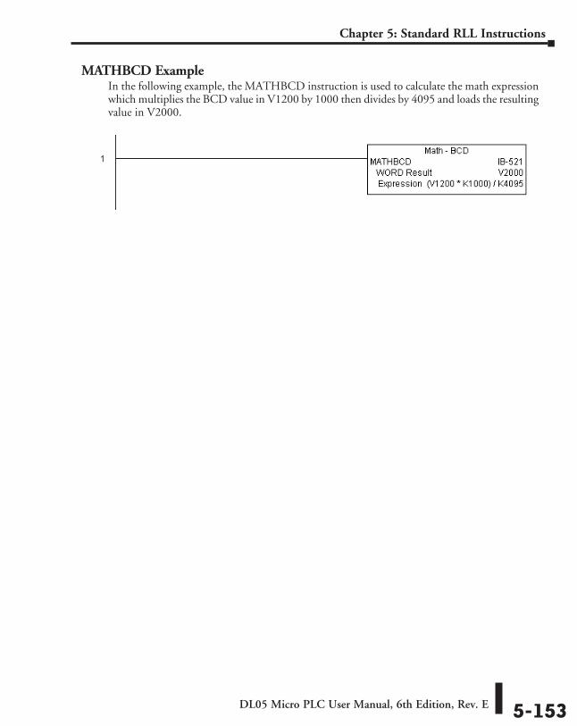
DL05 Micro PLC User Manual, 6th Edition, Rev. E 5-153
Chapter 5: Standard RLL Instructions
MATHBCD ExampleIn the following example, the MATHBCD instruction is used to calculate the math expression which multiplies the BCD value in V1200 by 1000 then divides by 4095 and loads the resulting value in V2000.
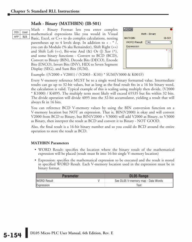
DL05 Micro PLC User Manual, 6th Edition, Rev. E5-154
Chapter 5: Standard RLL Instructions
Math - Binary (MATHBIN) (IB-501)Math - Binary Format lets you enter complex mathematical expressions like you would in Visual Basic, Excel, or C++ to do complex calculations, nesting parentheses up to 4 levels deep. In addition to + - * /, you can do Modulo (% aka Remainder), Shift Right (>>) and Shift Left (<<), Bit-wise And (&) Or (|) Xor (^), and some binary functions - Convert to BCD (BCD), Convert to Binary (BIN), Decode Bits (DECO), Encode Bits (ENCO), Invert Bits (INV), HEX to Seven Segment Display (SEG), and Sum Bits (SUM).
Example: ((V2000 + V2001) / (V2003 - K10)) * SUM(V3000 & K001F)
Every V-memory reference MUST be to a single word binary formatted value. Intermediate results can go up to 32-bit values, but as long as the final result fits in a 16 bit binary word, the calculation is valid. Typical example of this is scaling using multiply then divide, (V2000 * K1000) / K4095. The multiply term most likely will exceed 65535 but fits within 32 bits. The divide operation will divide 4095 into the 32-bit accumulator, yielding a result that will always fit in 16 bits.
You can reference BCD V-memory values by using the BIN conversion function on a V-memory location but NOT an expression. That is, BIN(V2000) is okay and will convert V2000 from BCD to Binary, but BIN(V2000 + V3000) will add V2000 as Binary, to V3000 as Binary, then interpret the result as BCD and convert it to Binary - NOT GOOD.
Also, the final result is a 16-bit binary number and so you could do BCD around the entire operation to store the result as BCD.
MATHBIN Parameters
• WORD Result: specifies the location where the binary result of the mathematical expression will be placed (result must fit into 16-bit single V-memory location)
• Expression: specifies the mathematical expression to be executed and the result is stored in specified WORD Result. Each V-memory location used in the expression must be in binary format.
Parameter DL05 RangeWORD Result ⸠⸠⸠⸠⸠⸠⸠⸠⸠⸠⸠⸠⸠⸠⸠⸠⸠⸠⸠⸠⸠⸠⸠⸠⸠⸠⸠⸠⸠⸠⸠⸠⸠⸠⸠⸠⸠⸠⸠⸠⸠⸠⸠⸠⸠⸠⸠⸠⸠⸠⸠⸠⸠⸠⸠⸠⸠⸠ V See DL05 V-memory map - Data WordsExpression ⸠⸠⸠⸠⸠⸠⸠⸠⸠⸠⸠⸠⸠⸠⸠⸠⸠⸠⸠⸠⸠⸠⸠⸠⸠⸠⸠⸠⸠⸠⸠⸠⸠⸠⸠⸠⸠⸠⸠⸠⸠⸠⸠⸠⸠⸠⸠⸠⸠⸠⸠⸠⸠⸠⸠⸠⸠⸠⸠⸠⸠⸠⸠⸠⸠⸠⸠⸠ Text
DS5 Used
HPP N/A
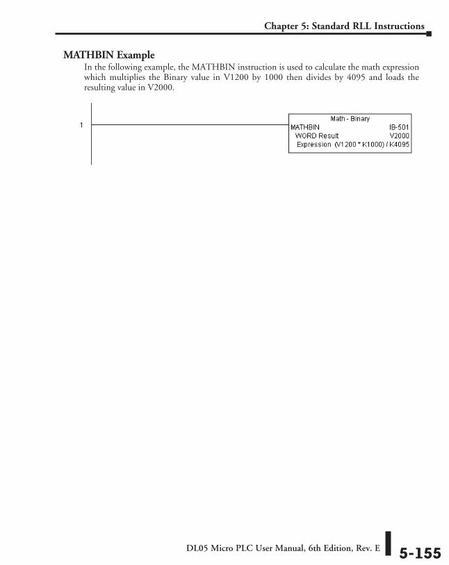
DL05 Micro PLC User Manual, 6th Edition, Rev. E 5-155
Chapter 5: Standard RLL Instructions
MATHBIN ExampleIn the following example, the MATHBIN instruction is used to calculate the math expression which multiplies the Binary value in V1200 by 1000 then divides by 4095 and loads the resulting value in V2000.
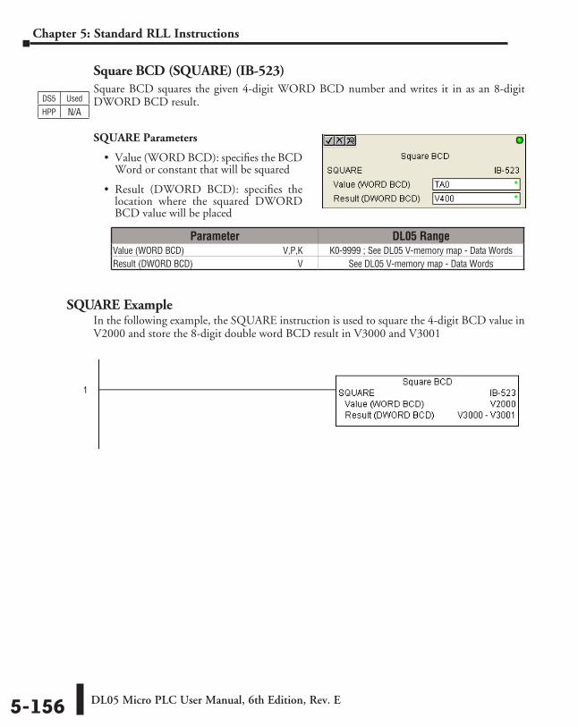
DL05 Micro PLC User Manual, 6th Edition, Rev. E5-156
Chapter 5: Standard RLL Instructions
Square BCD (SQUARE) (IB-523)Square BCD squares the given 4-digit WORD BCD number and writes it in as an 8-digit DWORD BCD result.
SQUARE Parameters
• Value (WORD BCD): specifies the BCD Word or constant that will be squared
• Result (DWORD BCD): specifies the location where the squared DWORD BCD value will be placed
SQUARE ExampleIn the following example, the SQUARE instruction is used to square the 4-digit BCD value in V2000 and store the 8-digit double word BCD result in V3000 and V3001
Parameter DL05 RangeValue (WORD BCD) ⸠⸠⸠⸠⸠⸠⸠⸠⸠⸠⸠⸠⸠⸠⸠⸠⸠⸠⸠⸠⸠⸠⸠⸠⸠⸠⸠⸠⸠⸠⸠⸠⸠⸠⸠⸠⸠⸠⸠⸠⸠⸠V,P,K K0-9999 ; See DL05 V-memory map - Data WordsResult (DWORD BCD) ⸠⸠⸠⸠⸠⸠⸠⸠⸠⸠⸠⸠⸠⸠⸠⸠⸠⸠⸠⸠⸠⸠⸠⸠⸠⸠⸠⸠⸠⸠⸠⸠⸠⸠⸠⸠⸠⸠⸠⸠⸠⸠⸠⸠⸠⸠ V See DL05 V-memory map - Data Words
DS5 Used
HPP N/A
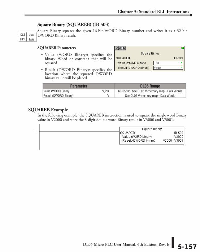
DL05 Micro PLC User Manual, 6th Edition, Rev. E 5-157
Chapter 5: Standard RLL Instructions
Square Binary (SQUAREB) (IB-503)Square Binary squares the given 16-bit WORD Binary number and writes it as a 32-bit DWORD Binary result.
SQUAREB Parameters
• Value (WORD Binary): specifies the binary Word or constant that will be squared
• Result (DWORD Binary): specifies the location where the squared DWORD binary value will be placed
SQUAREB ExampleIn the following example, the SQUAREB instruction is used to square the single word Binary value in V2000 and store the 8-digit double word Binary result in V3000 and V3001.
Parameter DL05 RangeValue (WORD Binary) ⸠⸠⸠⸠⸠⸠⸠⸠⸠⸠⸠⸠⸠⸠⸠⸠⸠⸠⸠⸠⸠⸠⸠⸠⸠⸠⸠⸠⸠⸠⸠⸠⸠⸠⸠⸠⸠⸠⸠V,P,K K0-65535; See DL05 V-memory map - Data WordsResult (DWORD Binary) ⸠⸠⸠⸠⸠⸠⸠⸠⸠⸠⸠⸠⸠⸠⸠⸠⸠⸠⸠⸠⸠⸠⸠⸠⸠⸠⸠⸠⸠⸠⸠⸠⸠⸠⸠⸠⸠⸠⸠⸠⸠⸠⸠ V See DL05 V-memory map - Data Words
DS5 Used
HPP N/A
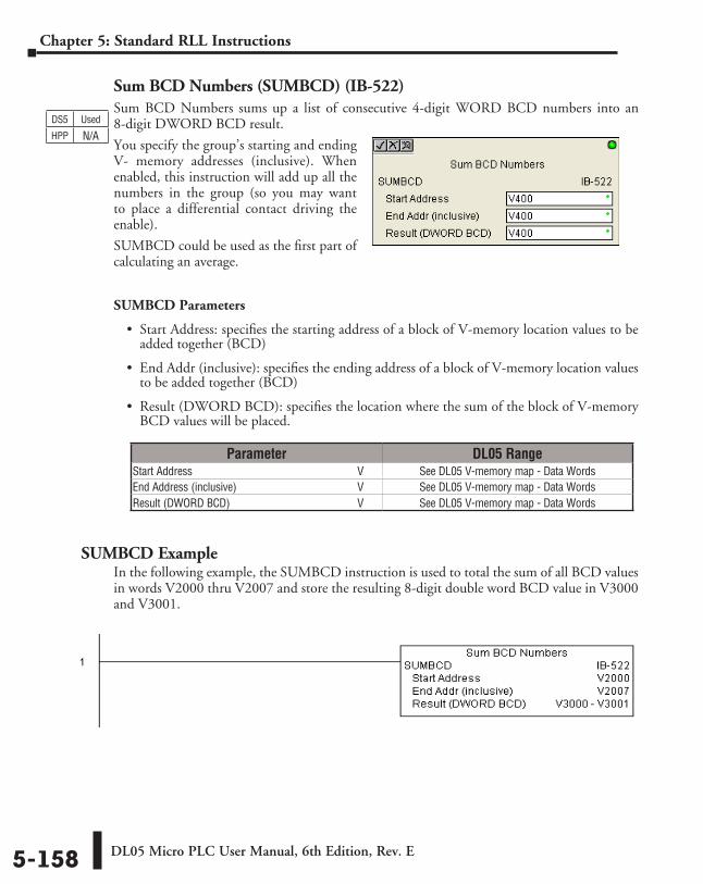
DL05 Micro PLC User Manual, 6th Edition, Rev. E5-158
Chapter 5: Standard RLL Instructions
Sum BCD Numbers (SUMBCD) (IB-522)Sum BCD Numbers sums up a list of consecutive 4-digit WORD BCD numbers into an 8-digit DWORD BCD result.
You specify the group’s starting and ending V- memory addresses (inclusive). When enabled, this instruction will add up all the numbers in the group (so you may want to place a differential contact driving the enable).
SUMBCD could be used as the first part of calculating an average.
SUMBCD Parameters
• Start Address: specifies the starting address of a block of V-memory location values to be added together (BCD)
• End Addr (inclusive): specifies the ending address of a block of V-memory location values to be added together (BCD)
• Result (DWORD BCD): specifies the location where the sum of the block of V-memory BCD values will be placed.
SUMBCD ExampleIn the following example, the SUMBCD instruction is used to total the sum of all BCD values in words V2000 thru V2007 and store the resulting 8-digit double word BCD value in V3000 and V3001.
Parameter DL05 RangeStart Address ⸠⸠⸠⸠⸠⸠⸠⸠⸠⸠⸠⸠⸠⸠⸠⸠⸠⸠⸠⸠⸠⸠⸠⸠⸠⸠⸠⸠⸠⸠⸠⸠⸠⸠⸠⸠⸠⸠⸠⸠⸠⸠⸠⸠⸠⸠⸠⸠⸠⸠⸠⸠⸠⸠⸠⸠⸠⸠ V See DL05 V-memory map - Data WordsEnd Address (inclusive) ⸠⸠⸠⸠⸠⸠⸠⸠⸠⸠⸠⸠⸠⸠⸠⸠⸠⸠⸠⸠⸠⸠⸠⸠⸠⸠⸠⸠⸠⸠⸠⸠⸠⸠⸠⸠⸠⸠⸠⸠⸠⸠ V See DL05 V-memory map - Data WordsResult (DWORD BCD) ⸠⸠⸠⸠⸠⸠⸠⸠⸠⸠⸠⸠⸠⸠⸠⸠⸠⸠⸠⸠⸠⸠⸠⸠⸠⸠⸠⸠⸠⸠⸠⸠⸠⸠⸠⸠⸠⸠⸠⸠⸠⸠⸠⸠⸠⸠ V See DL05 V-memory map - Data Words
DS5 Used
HPP N/A
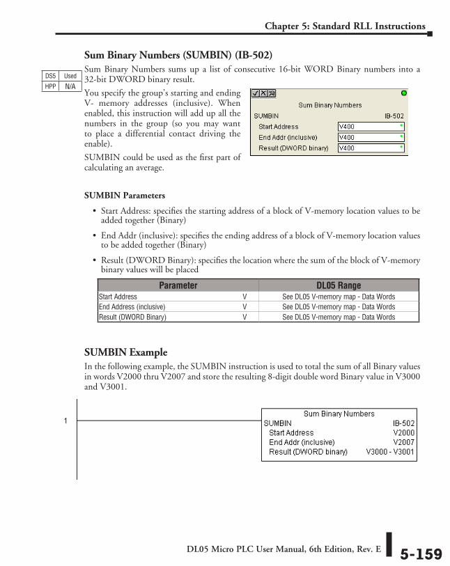
DL05 Micro PLC User Manual, 6th Edition, Rev. E 5-159
Chapter 5: Standard RLL Instructions
Sum Binary Numbers (SUMBIN) (IB-502)Sum Binary Numbers sums up a list of consecutive 16-bit WORD Binary numbers into a 32-bit DWORD binary result.
You specify the group’s starting and ending V- memory addresses (inclusive). When enabled, this instruction will add up all the numbers in the group (so you may want to place a differential contact driving the enable).
SUMBIN could be used as the first part of calculating an average.
SUMBIN Parameters
• Start Address: specifies the starting address of a block of V-memory location values to be added together (Binary)
• End Addr (inclusive): specifies the ending address of a block of V-memory location values to be added together (Binary)
• Result (DWORD Binary): specifies the location where the sum of the block of V-memory binary values will be placed
SUMBIN ExampleIn the following example, the SUMBIN instruction is used to total the sum of all Binary values in words V2000 thru V2007 and store the resulting 8-digit double word Binary value in V3000 and V3001.
Parameter DL05 RangeStart Address ⸠⸠⸠⸠⸠⸠⸠⸠⸠⸠⸠⸠⸠⸠⸠⸠⸠⸠⸠⸠⸠⸠⸠⸠⸠⸠⸠⸠⸠⸠⸠⸠⸠⸠⸠⸠⸠⸠⸠⸠⸠⸠⸠⸠⸠⸠⸠⸠⸠⸠⸠⸠⸠⸠⸠⸠⸠⸠ V See DL05 V-memory map - Data WordsEnd Address (inclusive) ⸠⸠⸠⸠⸠⸠⸠⸠⸠⸠⸠⸠⸠⸠⸠⸠⸠⸠⸠⸠⸠⸠⸠⸠⸠⸠⸠⸠⸠⸠⸠⸠⸠⸠⸠⸠⸠⸠⸠⸠⸠⸠ V See DL05 V-memory map - Data WordsResult (DWORD Binary) ⸠⸠⸠⸠⸠⸠⸠⸠⸠⸠⸠⸠⸠⸠⸠⸠⸠⸠⸠⸠⸠⸠⸠⸠⸠⸠⸠⸠⸠⸠⸠⸠⸠⸠⸠⸠⸠⸠⸠⸠⸠⸠⸠ V See DL05 V-memory map - Data Words
DS5 Used
HPP N/A
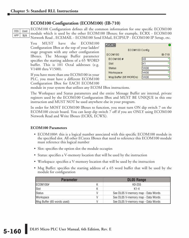
DL05 Micro PLC User Manual, 6th Edition, Rev. E5-160
Chapter 5: Standard RLL Instructions
ECOM100 Configuration (ECOM100) (IB-710)ECOM100 Configuration defines all the common information for one specific ECOM100 module which is used by the other ECOM100 IBoxes; for example, ECRX - ECOM100 Network Read , ECEMAIL - ECOM100 Send EMail, ECIPSUP - ECOM100 IP Setup, etc.
You MUST have the ECOM100 Configuration IBox at the top of your ladder/stage program with any other configuration IBoxes. The Message Buffer parameter specifies the starting address of a 65 WORD buffer. This is 101 Octal addresses (e.g. V1400 thru V1500).
If you have more than one ECOM100 in your PLC, you must have a different ECOM100 Configuration IBox for EACH ECOM100 module in your system that utilizes any ECOM IBox instructions.
The Workspace and Status parameters and the entire Message Buffer are internal, private registers used by the ECOM100 Configuration IBox and MUST BE UNIQUE in this one instruction and MUST NOT be used anywhere else in your program.
In order for MOST ECOM100 IBoxes to function, you must turn ON dip switch 7 on the ECOM100 circuit board. You can keep dip switch 7 off if you are ONLY using ECOM100 Network Read and Write IBoxes (ECRX, ECWX).
ECOM100 Parameters
• ECOM100#: this is a logical number associated with this specific ECOM100 module in the specified slot. All other ECxxxx IBoxes that need to reference this ECOM100 module must reference this logical number
• Slot: specifies the option slot the module occupies
• Status: specifies a V-memory location that will be used by the instruction
• Workspace: specifies a V-memory location that will be used by the instruction
• Msg Buffer: specifies the starting address of a 65 word buffer that will be used by the module for configuration
DS5 Used
HPP N/A
Parameter DL05 RangeECOM100# ⸠⸠⸠⸠⸠⸠⸠⸠⸠⸠⸠⸠⸠⸠⸠⸠⸠⸠⸠⸠⸠⸠⸠⸠⸠⸠⸠⸠⸠⸠⸠⸠⸠⸠⸠⸠⸠⸠⸠⸠⸠⸠⸠⸠⸠⸠⸠⸠⸠⸠⸠⸠⸠⸠⸠⸠⸠⸠⸠⸠⸠⸠ K K0-255Slot ⸠⸠⸠⸠⸠⸠⸠⸠⸠⸠⸠⸠⸠⸠⸠⸠⸠⸠⸠⸠⸠⸠⸠⸠⸠⸠⸠⸠⸠⸠⸠⸠⸠⸠⸠⸠⸠⸠⸠⸠⸠⸠⸠⸠⸠⸠⸠⸠⸠⸠⸠⸠⸠⸠⸠⸠⸠⸠⸠⸠⸠⸠⸠⸠⸠⸠⸠⸠⸠⸠⸠⸠⸠⸠ K K1-4Status ⸠⸠⸠⸠⸠⸠⸠⸠⸠⸠⸠⸠⸠⸠⸠⸠⸠⸠⸠⸠⸠⸠⸠⸠⸠⸠⸠⸠⸠⸠⸠⸠⸠⸠⸠⸠⸠⸠⸠⸠⸠⸠⸠⸠⸠⸠⸠⸠⸠⸠⸠⸠⸠⸠⸠⸠⸠⸠⸠⸠⸠⸠⸠⸠⸠⸠⸠⸠⸠⸠ V See DL05 V-memory map - Data WordsWorkspace ⸠⸠⸠⸠⸠⸠⸠⸠⸠⸠⸠⸠⸠⸠⸠⸠⸠⸠⸠⸠⸠⸠⸠⸠⸠⸠⸠⸠⸠⸠⸠⸠⸠⸠⸠⸠⸠⸠⸠⸠⸠⸠⸠⸠⸠⸠⸠⸠⸠⸠⸠⸠⸠⸠⸠⸠⸠⸠⸠⸠⸠⸠ V See DL05 V-memory map - Data WordsMsg Buffer (65 words used) ⸠⸠⸠⸠⸠⸠⸠⸠⸠⸠⸠⸠⸠⸠⸠⸠⸠⸠⸠⸠⸠⸠⸠⸠⸠⸠⸠⸠⸠⸠⸠⸠⸠⸠⸠⸠ V See DL05 V-memory map - Data Words
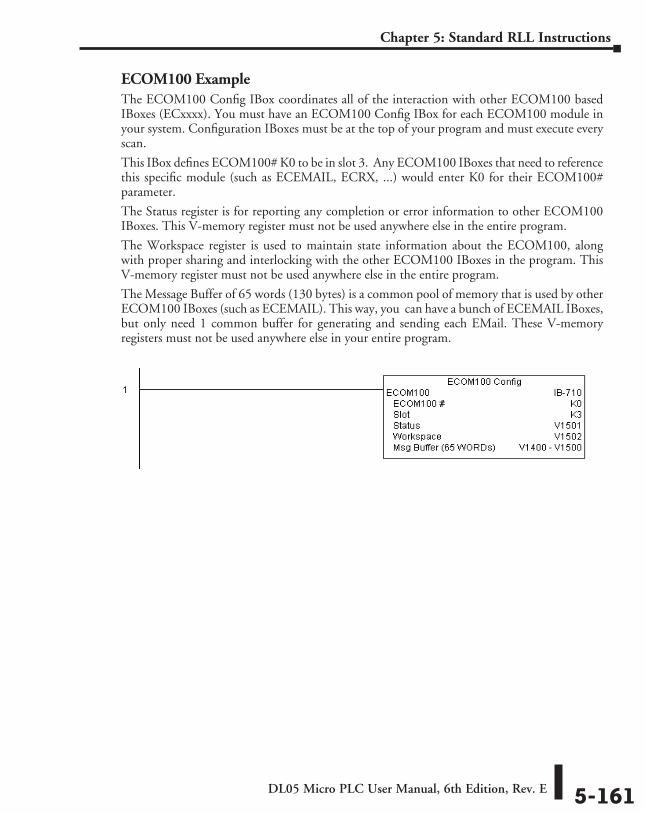
DL05 Micro PLC User Manual, 6th Edition, Rev. E 5-161
Chapter 5: Standard RLL Instructions
ECOM100 ExampleThe ECOM100 Config IBox coordinates all of the interaction with other ECOM100 based IBoxes (ECxxxx). You must have an ECOM100 Config IBox for each ECOM100 module in your system. Configuration IBoxes must be at the top of your program and must execute every scan.
This IBox defines ECOM100# K0 to be in slot 3. Any ECOM100 IBoxes that need to reference this specific module (such as ECEMAIL, ECRX, ...) would enter K0 for their ECOM100# parameter.
The Status register is for reporting any completion or error information to other ECOM100 IBoxes. This V-memory register must not be used anywhere else in the entire program.
The Workspace register is used to maintain state information about the ECOM100, along with proper sharing and interlocking with the other ECOM100 IBoxes in the program. This V-memory register must not be used anywhere else in the entire program.
The Message Buffer of 65 words (130 bytes) is a common pool of memory that is used by other ECOM100 IBoxes (such as ECEMAIL). This way, you can have a bunch of ECEMAIL IBoxes, but only need 1 common buffer for generating and sending each EMail. These V-memory registers must not be used anywhere else in your entire program.
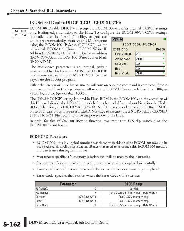
DL05 Micro PLC User Manual, 6th Edition, Rev. E5-162
Chapter 5: Standard RLL Instructions
ECOM100 Disable DHCP (ECDHCPD) (IB-736)ECOM100 Disable DHCP will setup the ECOM100 to use its internal TCP/IP settings on a leading edge transition to the IBox. To configure the ECOM100’s TCP/IP settings manually, use the NetEdit3 utility, or you can do it programmatically from your PLC program using the ECOM100 IP Setup (ECIPSUP), or the individual ECOM100 IBoxes: ECOM Write IP Address (ECWRIP), ECOM Write Gateway Address (ECWRGWA), and ECOM100 Write Subnet Mask (ECWRSNM).
The Workspace parameter is an internal, private register used by this IBox and MUST BE UNIQUE in this one instruction and MUST NOT be used anywhere else in your program.
Either the Success or Error bit parameter will turn on once the command is complete. If there is an error, the Error Code parameter will report an ECOM100 error code (less than 100), or a PLC logic error (greater than 1000).
The “Disable DHCP” setting is stored in Flash-ROM in the ECOM100 and the execution of this IBox will disable the ECOM100 module for at least a half second until it writes the Flash-ROM. Therefore, it is HIGHLY RECOMMENDED that you only execute this IBox ONCE, on second scan. Since it requires a LEADING edge to execute, use a NORMALLY CLOSED SP0 (STR NOT First Scan) to drive the power flow to the IBox.
In order for this ECOM100 IBox to function, you must turn ON dip switch 7 on the ECOM100 circuit board.
ECDHCPD Parameters
• ECOM100#: this is a logical number associated with this specific ECOM100 module in the specified slot. All other ECxxxx IBoxes that need to reference this ECOM100 module must reference this logical number
• Workspace: specifies a V-memory location that will be used by the instruction
• Success: specifies a bit that will turn on once the request is completed successfully
• Error: specifies a bit that will turn on if the instruction is not successfully completed
• Error Code: specifies the location where the Error Code will be written
Parameter DL05 RangeECOM100# ⸠⸠⸠⸠⸠⸠⸠⸠⸠⸠⸠⸠⸠⸠⸠⸠⸠⸠⸠⸠⸠⸠⸠⸠⸠⸠⸠⸠⸠⸠⸠⸠⸠⸠⸠⸠⸠⸠⸠⸠⸠⸠⸠⸠⸠⸠⸠⸠⸠⸠⸠⸠⸠⸠⸠⸠⸠⸠⸠⸠⸠⸠ K K0-255Workspace ⸠⸠⸠⸠⸠⸠⸠⸠⸠⸠⸠⸠⸠⸠⸠⸠⸠⸠⸠⸠⸠⸠⸠⸠⸠⸠⸠⸠⸠⸠⸠⸠⸠⸠⸠⸠⸠⸠⸠⸠⸠⸠⸠⸠⸠⸠⸠⸠⸠⸠⸠⸠⸠⸠⸠⸠⸠⸠⸠⸠⸠⸠ V See DL05 V-memory map - Data WordsSuccess ⸠⸠⸠⸠⸠⸠⸠⸠⸠⸠⸠⸠⸠⸠⸠⸠⸠⸠⸠⸠⸠⸠⸠⸠⸠⸠⸠⸠⸠⸠⸠⸠⸠⸠⸠⸠⸠⸠⸠⸠⸠⸠⸠⸠⸠ X,Y,C,GX,GY,B See DL05 V-memory mapError ⸠⸠⸠⸠⸠⸠⸠⸠⸠⸠⸠⸠⸠⸠⸠⸠⸠⸠⸠⸠⸠⸠⸠⸠⸠⸠⸠⸠⸠⸠⸠⸠⸠⸠⸠⸠⸠⸠⸠⸠⸠⸠⸠⸠⸠⸠⸠⸠⸠⸠ X,Y,C,GX,GY,B See DL05 V-memory mapError Code ⸠⸠⸠⸠⸠⸠⸠⸠⸠⸠⸠⸠⸠⸠⸠⸠⸠⸠⸠⸠⸠⸠⸠⸠⸠⸠⸠⸠⸠⸠⸠⸠⸠⸠⸠⸠⸠⸠⸠⸠⸠⸠⸠⸠⸠⸠⸠⸠⸠⸠⸠⸠⸠⸠⸠⸠⸠⸠⸠⸠⸠⸠⸠⸠⸠ V See DL05 V-memory map - Data Words
DS5 Used
HPP N/A
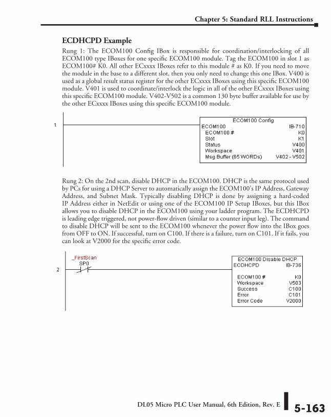
DL05 Micro PLC User Manual, 6th Edition, Rev. E 5-163
Chapter 5: Standard RLL Instructions
ECDHCPD ExampleRung 1: The ECOM100 Config IBox is responsible for coordination/interlocking of all ECOM100 type IBoxes for one specific ECOM100 module. Tag the ECOM100 in slot 1 as ECOM100# K0. All other ECxxxx IBoxes refer to this module # as K0. If you need to move the module in the base to a different slot, then you only need to change this one IBox. V400 is used as a global result status register for the other ECxxxx IBoxes using this specific ECOM100 module. V401 is used to coordinate/interlock the logic in all of the other ECxxxx IBoxes using this specific ECOM100 module. V402-V502 is a common 130 byte buffer available for use by the other ECxxxx IBoxes using this specific ECOM100 module.
Rung 2: On the 2nd scan, disable DHCP in the ECOM100. DHCP is the same protocol used by PCs for using a DHCP Server to automatically assign the ECOM100’s IP Address, Gateway Address, and Subnet Mask. Typically disabling DHCP is done by assigning a hard-coded IP Address either in NetEdit or using one of the ECOM100 IP Setup IBoxes, but this IBox allows you to disable DHCP in the ECOM100 using your ladder program. The ECDHCPD is leading edge triggered, not power-flow driven (similar to a counter input leg). The command to disable DHCP will be sent to the ECOM100 whenever the power flow into the IBox goes from OFF to ON. If successful, turn on C100. If there is a failure, turn on C101. If it fails, you can look at V2000 for the specific error code.
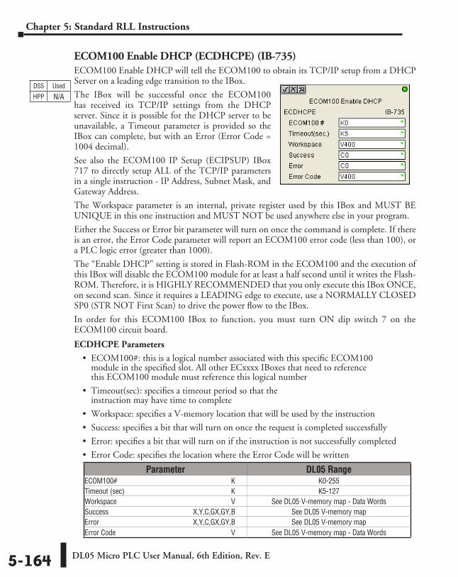
DL05 Micro PLC User Manual, 6th Edition, Rev. E5-164
Chapter 5: Standard RLL Instructions
ECOM100 Enable DHCP (ECDHCPE) (IB-735)ECOM100 Enable DHCP will tell the ECOM100 to obtain its TCP/IP setup from a DHCP Server on a leading edge transition to the IBox.
The IBox will be successful once the ECOM100 has received its TCP/IP settings from the DHCP server. Since it is possible for the DHCP server to be unavailable, a Timeout parameter is provided so the IBox can complete, but with an Error (Error Code = 1004 decimal).
See also the ECOM100 IP Setup (ECIPSUP) IBox 717 to directly setup ALL of the TCP/IP parameters in a single instruction - IP Address, Subnet Mask, and Gateway Address.
The Workspace parameter is an internal, private register used by this IBox and MUST BE UNIQUE in this one instruction and MUST NOT be used anywhere else in your program.
Either the Success or Error bit parameter will turn on once the command is complete. If there is an error, the Error Code parameter will report an ECOM100 error code (less than 100), or a PLC logic error (greater than 1000).
The “Enable DHCP” setting is stored in Flash-ROM in the ECOM100 and the execution of this IBox will disable the ECOM100 module for at least a half second until it writes the Flash-ROM. Therefore, it is HIGHLY RECOMMENDED that you only execute this IBox ONCE, on second scan. Since it requires a LEADING edge to execute, use a NORMALLY CLOSED SP0 (STR NOT First Scan) to drive the power flow to the IBox.
In order for this ECOM100 IBox to function, you must turn ON dip switch 7 on the ECOM100 circuit board.
ECDHCPE Parameters
• ECOM100#: this is a logical number associated with this specific ECOM100 module in the specified slot. All other ECxxxx IBoxes that need to reference this ECOM100 module must reference this logical number
• Timeout(sec): specifies a timeout period so that the instruction may have time to complete
• Workspace: specifies a V-memory location that will be used by the instruction
• Success: specifies a bit that will turn on once the request is completed successfully
• Error: specifies a bit that will turn on if the instruction is not successfully completed
• Error Code: specifies the location where the Error Code will be written
Parameter DL05 RangeECOM100# ⸠⸠⸠⸠⸠⸠⸠⸠⸠⸠⸠⸠⸠⸠⸠⸠⸠⸠⸠⸠⸠⸠⸠⸠⸠⸠⸠⸠⸠⸠⸠⸠⸠⸠⸠⸠⸠⸠⸠⸠⸠⸠⸠⸠⸠⸠⸠⸠⸠⸠⸠⸠⸠⸠⸠⸠⸠⸠⸠⸠⸠⸠ K K0-255Timeout (sec) ⸠⸠⸠⸠⸠⸠⸠⸠⸠⸠⸠⸠⸠⸠⸠⸠⸠⸠⸠⸠⸠⸠⸠⸠⸠⸠⸠⸠⸠⸠⸠⸠⸠⸠⸠⸠⸠⸠⸠⸠⸠⸠⸠⸠⸠⸠⸠⸠⸠⸠⸠⸠⸠⸠⸠⸠⸠⸠ K K5-127Workspace ⸠⸠⸠⸠⸠⸠⸠⸠⸠⸠⸠⸠⸠⸠⸠⸠⸠⸠⸠⸠⸠⸠⸠⸠⸠⸠⸠⸠⸠⸠⸠⸠⸠⸠⸠⸠⸠⸠⸠⸠⸠⸠⸠⸠⸠⸠⸠⸠⸠⸠⸠⸠⸠⸠⸠⸠⸠⸠⸠⸠⸠⸠ V See DL05 V-memory map - Data WordsSuccess ⸠⸠⸠⸠⸠⸠⸠⸠⸠⸠⸠⸠⸠⸠⸠⸠⸠⸠⸠⸠⸠⸠⸠⸠⸠⸠⸠⸠⸠⸠⸠⸠⸠⸠⸠⸠⸠⸠⸠⸠⸠⸠⸠⸠⸠ X,Y,C,GX,GY,B See DL05 V-memory mapError ⸠⸠⸠⸠⸠⸠⸠⸠⸠⸠⸠⸠⸠⸠⸠⸠⸠⸠⸠⸠⸠⸠⸠⸠⸠⸠⸠⸠⸠⸠⸠⸠⸠⸠⸠⸠⸠⸠⸠⸠⸠⸠⸠⸠⸠⸠⸠⸠⸠⸠ X,Y,C,GX,GY,B See DL05 V-memory mapError Code ⸠⸠⸠⸠⸠⸠⸠⸠⸠⸠⸠⸠⸠⸠⸠⸠⸠⸠⸠⸠⸠⸠⸠⸠⸠⸠⸠⸠⸠⸠⸠⸠⸠⸠⸠⸠⸠⸠⸠⸠⸠⸠⸠⸠⸠⸠⸠⸠⸠⸠⸠⸠⸠⸠⸠⸠⸠⸠⸠⸠⸠⸠⸠⸠⸠ V See DL05 V-memory map - Data Words
DS5 Used
HPP N/A
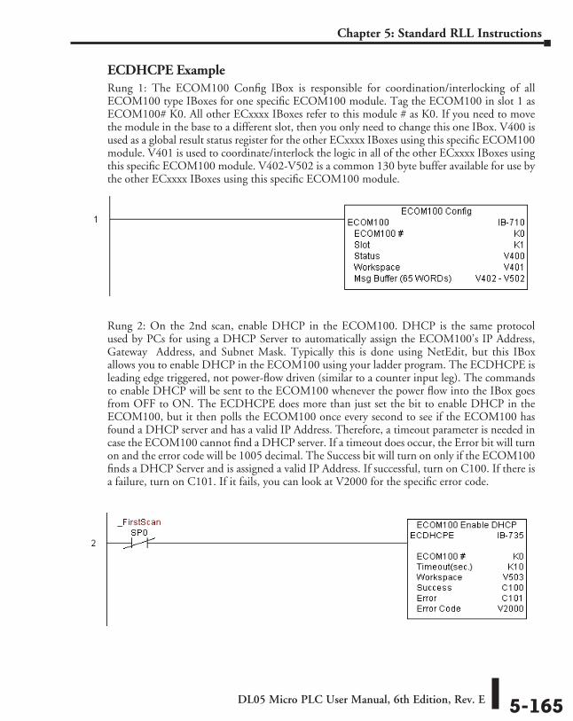
DL05 Micro PLC User Manual, 6th Edition, Rev. E 5-165
Chapter 5: Standard RLL Instructions
ECDHCPE ExampleRung 1: The ECOM100 Config IBox is responsible for coordination/interlocking of all ECOM100 type IBoxes for one specific ECOM100 module. Tag the ECOM100 in slot 1 as ECOM100# K0. All other ECxxxx IBoxes refer to this module # as K0. If you need to move the module in the base to a different slot, then you only need to change this one IBox. V400 is used as a global result status register for the other ECxxxx IBoxes using this specific ECOM100 module. V401 is used to coordinate/interlock the logic in all of the other ECxxxx IBoxes using this specific ECOM100 module. V402-V502 is a common 130 byte buffer available for use by the other ECxxxx IBoxes using this specific ECOM100 module.
Rung 2: On the 2nd scan, enable DHCP in the ECOM100. DHCP is the same protocol used by PCs for using a DHCP Server to automatically assign the ECOM100’s IP Address, Gateway Address, and Subnet Mask. Typically this is done using NetEdit, but this IBox allows you to enable DHCP in the ECOM100 using your ladder program. The ECDHCPE is leading edge triggered, not power-flow driven (similar to a counter input leg). The commands to enable DHCP will be sent to the ECOM100 whenever the power flow into the IBox goes from OFF to ON. The ECDHCPE does more than just set the bit to enable DHCP in the ECOM100, but it then polls the ECOM100 once every second to see if the ECOM100 has found a DHCP server and has a valid IP Address. Therefore, a timeout parameter is needed in case the ECOM100 cannot find a DHCP server. If a timeout does occur, the Error bit will turn on and the error code will be 1005 decimal. The Success bit will turn on only if the ECOM100 finds a DHCP Server and is assigned a valid IP Address. If successful, turn on C100. If there is a failure, turn on C101. If it fails, you can look at V2000 for the specific error code.
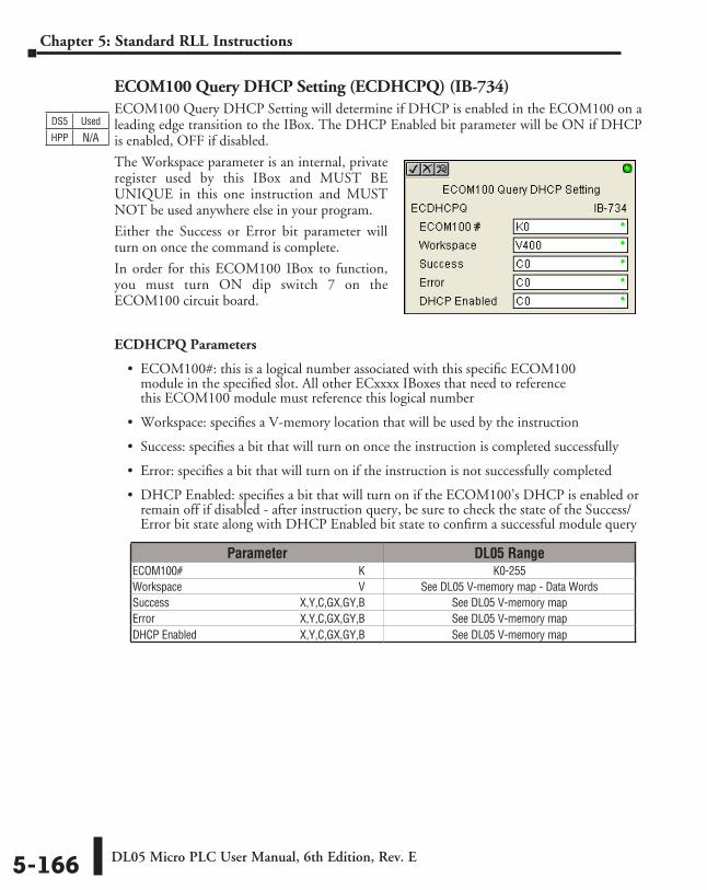
DL05 Micro PLC User Manual, 6th Edition, Rev. E5-166
Chapter 5: Standard RLL Instructions
ECOM100 Query DHCP Setting (ECDHCPQ) (IB-734)ECOM100 Query DHCP Setting will determine if DHCP is enabled in the ECOM100 on a leading edge transition to the IBox. The DHCP Enabled bit parameter will be ON if DHCP is enabled, OFF if disabled.
The Workspace parameter is an internal, private register used by this IBox and MUST BE UNIQUE in this one instruction and MUST NOT be used anywhere else in your program.
Either the Success or Error bit parameter will turn on once the command is complete.
In order for this ECOM100 IBox to function, you must turn ON dip switch 7 on the ECOM100 circuit board.
ECDHCPQ Parameters
• ECOM100#: this is a logical number associated with this specific ECOM100 module in the specified slot. All other ECxxxx IBoxes that need to reference this ECOM100 module must reference this logical number
• Workspace: specifies a V-memory location that will be used by the instruction
• Success: specifies a bit that will turn on once the instruction is completed successfully
• Error: specifies a bit that will turn on if the instruction is not successfully completed
• DHCP Enabled: specifies a bit that will turn on if the ECOM100’s DHCP is enabled or remain off if disabled - after instruction query, be sure to check the state of the Success/Error bit state along with DHCP Enabled bit state to confirm a successful module query
Parameter DL05 RangeECOM100# ⸠⸠⸠⸠⸠⸠⸠⸠⸠⸠⸠⸠⸠⸠⸠⸠⸠⸠⸠⸠⸠⸠⸠⸠⸠⸠⸠⸠⸠⸠⸠⸠⸠⸠⸠⸠⸠⸠⸠⸠⸠⸠⸠⸠⸠⸠⸠⸠⸠⸠⸠⸠⸠⸠⸠⸠⸠⸠⸠⸠⸠⸠ K K0-255Workspace ⸠⸠⸠⸠⸠⸠⸠⸠⸠⸠⸠⸠⸠⸠⸠⸠⸠⸠⸠⸠⸠⸠⸠⸠⸠⸠⸠⸠⸠⸠⸠⸠⸠⸠⸠⸠⸠⸠⸠⸠⸠⸠⸠⸠⸠⸠⸠⸠⸠⸠⸠⸠⸠⸠⸠⸠⸠⸠⸠⸠⸠⸠ V See DL05 V-memory map - Data WordsSuccess ⸠⸠⸠⸠⸠⸠⸠⸠⸠⸠⸠⸠⸠⸠⸠⸠⸠⸠⸠⸠⸠⸠⸠⸠⸠⸠⸠⸠⸠⸠⸠⸠⸠⸠⸠⸠⸠⸠⸠⸠⸠⸠⸠⸠⸠ X,Y,C,GX,GY,B See DL05 V-memory mapError ⸠⸠⸠⸠⸠⸠⸠⸠⸠⸠⸠⸠⸠⸠⸠⸠⸠⸠⸠⸠⸠⸠⸠⸠⸠⸠⸠⸠⸠⸠⸠⸠⸠⸠⸠⸠⸠⸠⸠⸠⸠⸠⸠⸠⸠⸠⸠⸠⸠⸠ X,Y,C,GX,GY,B See DL05 V-memory mapDHCP Enabled ⸠⸠⸠⸠⸠⸠⸠⸠⸠⸠⸠⸠⸠⸠⸠⸠⸠⸠⸠⸠⸠⸠⸠⸠⸠⸠⸠⸠⸠⸠⸠⸠⸠⸠⸠⸠⸠ X,Y,C,GX,GY,B See DL05 V-memory map
DS5 Used
HPP N/A
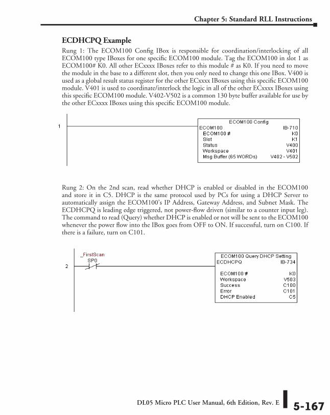
DL05 Micro PLC User Manual, 6th Edition, Rev. E 5-167
Chapter 5: Standard RLL Instructions
ECDHCPQ ExampleRung 1: The ECOM100 Config IBox is responsible for coordination/interlocking of all ECOM100 type IBoxes for one specific ECOM100 module. Tag the ECOM100 in slot 1 as ECOM100# K0. All other ECxxxx IBoxes refer to this module # as K0. If you need to move the module in the base to a different slot, then you only need to change this one IBox. V400 is used as a global result status register for the other ECxxxx IBoxes using this specific ECOM100 module. V401 is used to coordinate/interlock the logic in all of the other ECxxxx IBoxes using this specific ECOM100 module. V402-V502 is a common 130 byte buffer available for use by the other ECxxxx IBoxes using this specific ECOM100 module.
Rung 2: On the 2nd scan, read whether DHCP is enabled or disabled in the ECOM100 and store it in C5. DHCP is the same protocol used by PCs for using a DHCP Server to automatically assign the ECOM100’s IP Address, Gateway Address, and Subnet Mask. The ECDHCPQ is leading edge triggered, not power-flow driven (similar to a counter input leg). The command to read (Query) whether DHCP is enabled or not will be sent to the ECOM100 whenever the power flow into the IBox goes from OFF to ON. If successful, turn on C100. If there is a failure, turn on C101.
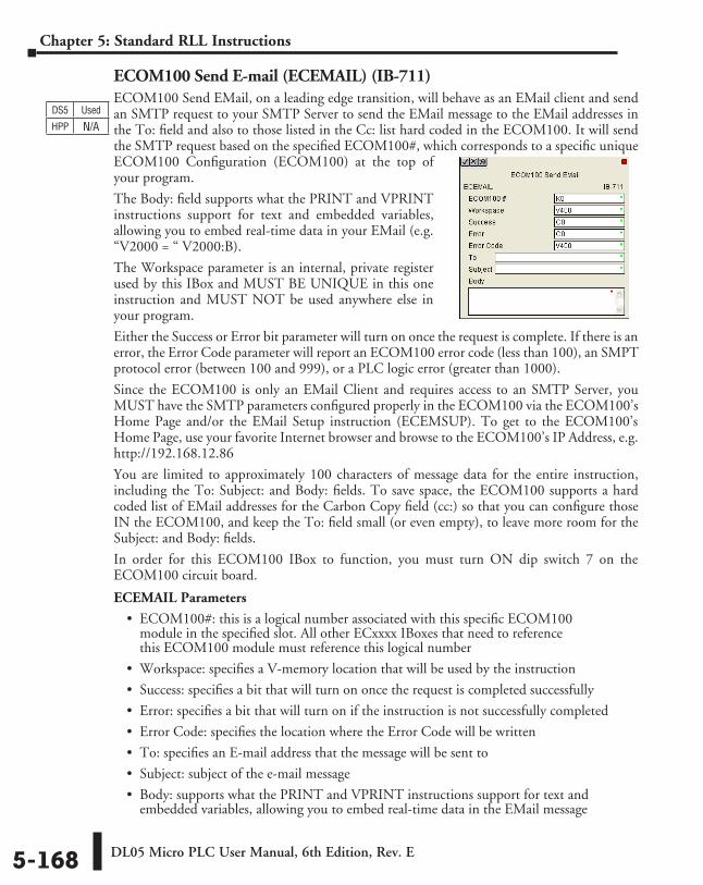
DL05 Micro PLC User Manual, 6th Edition, Rev. E5-168
Chapter 5: Standard RLL Instructions
ECOM100 Send E-mail (ECEMAIL) (IB-711)ECOM100 Send EMail, on a leading edge transition, will behave as an EMail client and send an SMTP request to your SMTP Server to send the EMail message to the EMail addresses in the To: field and also to those listed in the Cc: list hard coded in the ECOM100. It will send the SMTP request based on the specified ECOM100#, which corresponds to a specific unique ECOM100 Configuration (ECOM100) at the top of your program.
The Body: field supports what the PRINT and VPRINT instructions support for text and embedded variables, allowing you to embed real-time data in your EMail (e.g. “V2000 = “ V2000:B).
The Workspace parameter is an internal, private register used by this IBox and MUST BE UNIQUE in this one instruction and MUST NOT be used anywhere else in your program.
Either the Success or Error bit parameter will turn on once the request is complete. If there is an error, the Error Code parameter will report an ECOM100 error code (less than 100), an SMPT protocol error (between 100 and 999), or a PLC logic error (greater than 1000).
Since the ECOM100 is only an EMail Client and requires access to an SMTP Server, you MUST have the SMTP parameters configured properly in the ECOM100 via the ECOM100’s Home Page and/or the EMail Setup instruction (ECEMSUP). To get to the ECOM100’s Home Page, use your favorite Internet browser and browse to the ECOM100’s IP Address, e.g. http://192.168.12.86
You are limited to approximately 100 characters of message data for the entire instruction, including the To: Subject: and Body: fields. To save space, the ECOM100 supports a hard coded list of EMail addresses for the Carbon Copy field (cc:) so that you can configure those IN the ECOM100, and keep the To: field small (or even empty), to leave more room for the Subject: and Body: fields.
In order for this ECOM100 IBox to function, you must turn ON dip switch 7 on the ECOM100 circuit board.
ECEMAIL Parameters
• ECOM100#: this is a logical number associated with this specific ECOM100 module in the specified slot. All other ECxxxx IBoxes that need to reference this ECOM100 module must reference this logical number
• Workspace: specifies a V-memory location that will be used by the instruction
• Success: specifies a bit that will turn on once the request is completed successfully
• Error: specifies a bit that will turn on if the instruction is not successfully completed
• Error Code: specifies the location where the Error Code will be written
• To: specifies an E-mail address that the message will be sent to
• Subject: subject of the e-mail message
• Body: supports what the PRINT and VPRINT instructions support for text and embedded variables, allowing you to embed real-time data in the EMail message
DS5 Used
HPP N/A
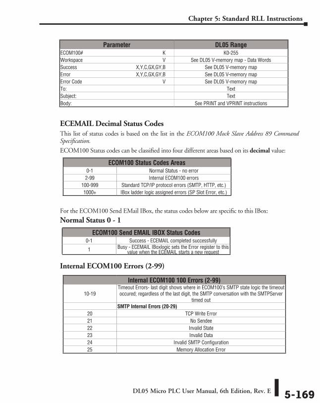
DL05 Micro PLC User Manual, 6th Edition, Rev. E 5-169
Chapter 5: Standard RLL Instructions
ECEMAIL Decimal Status CodesThis list of status codes is based on the list in the ECOM100 Mock Slave Address 89 Command Specification.
ECOM100 Status codes can be classified into four different areas based on its decimal value:
For the ECOM100 Send EMail IBox, the status codes below are specific to this IBox:
Normal Status 0 - 1
Internal ECOM100 Errors (2-99)
Parameter DL05 RangeECOM100# ⸠⸠⸠⸠⸠⸠⸠⸠⸠⸠⸠⸠⸠⸠⸠⸠⸠⸠⸠⸠⸠⸠⸠⸠⸠⸠⸠⸠⸠⸠⸠⸠⸠⸠⸠⸠⸠⸠⸠⸠⸠⸠⸠⸠⸠⸠⸠⸠⸠⸠⸠⸠⸠⸠⸠⸠⸠⸠⸠⸠⸠⸠ K K0-255Workspace ⸠⸠⸠⸠⸠⸠⸠⸠⸠⸠⸠⸠⸠⸠⸠⸠⸠⸠⸠⸠⸠⸠⸠⸠⸠⸠⸠⸠⸠⸠⸠⸠⸠⸠⸠⸠⸠⸠⸠⸠⸠⸠⸠⸠⸠⸠⸠⸠⸠⸠⸠⸠⸠⸠⸠⸠⸠⸠⸠⸠⸠⸠ V See DL05 V-memory map - Data WordsSuccess ⸠⸠⸠⸠⸠⸠⸠⸠⸠⸠⸠⸠⸠⸠⸠⸠⸠⸠⸠⸠⸠⸠⸠⸠⸠⸠⸠⸠⸠⸠⸠⸠⸠⸠⸠⸠⸠⸠⸠⸠⸠⸠⸠⸠⸠ X,Y,C,GX,GY,B See DL05 V-memory mapError ⸠⸠⸠⸠⸠⸠⸠⸠⸠⸠⸠⸠⸠⸠⸠⸠⸠⸠⸠⸠⸠⸠⸠⸠⸠⸠⸠⸠⸠⸠⸠⸠⸠⸠⸠⸠⸠⸠⸠⸠⸠⸠⸠⸠⸠⸠⸠⸠⸠⸠ X,Y,C,GX,GY,B See DL05 V-memory mapError Code ⸠⸠⸠⸠⸠⸠⸠⸠⸠⸠⸠⸠⸠⸠⸠⸠⸠⸠⸠⸠⸠⸠⸠⸠⸠⸠⸠⸠⸠⸠⸠⸠⸠⸠⸠⸠⸠⸠⸠⸠⸠⸠⸠⸠⸠⸠⸠⸠⸠⸠⸠⸠⸠⸠⸠⸠⸠⸠⸠⸠⸠⸠⸠⸠⸠ V See DL05 V-memory mapTo: ⸠⸠⸠⸠⸠⸠⸠⸠⸠⸠⸠⸠⸠⸠⸠⸠⸠⸠⸠⸠⸠⸠⸠⸠⸠⸠⸠⸠⸠⸠⸠⸠⸠⸠⸠⸠⸠⸠⸠⸠⸠⸠⸠⸠⸠⸠⸠⸠⸠⸠⸠⸠⸠⸠⸠⸠⸠⸠⸠⸠⸠⸠⸠⸠⸠⸠⸠⸠⸠⸠⸠⸠⸠⸠⸠⸠⸠⸠⸠⸠ TextSubject: ⸠⸠⸠⸠⸠⸠⸠⸠⸠⸠⸠⸠⸠⸠⸠⸠⸠⸠⸠⸠⸠⸠⸠⸠⸠⸠⸠⸠⸠⸠⸠⸠⸠⸠⸠⸠⸠⸠⸠⸠⸠⸠⸠⸠⸠⸠⸠⸠⸠⸠⸠⸠⸠⸠⸠⸠⸠⸠⸠⸠⸠⸠⸠⸠⸠⸠⸠⸠⸠⸠⸠⸠ TextBody: ⸠⸠⸠⸠⸠⸠⸠⸠⸠⸠⸠⸠⸠⸠⸠⸠⸠⸠⸠⸠⸠⸠⸠⸠⸠⸠⸠⸠⸠⸠⸠⸠⸠⸠⸠⸠⸠⸠⸠⸠⸠⸠⸠⸠⸠⸠⸠⸠⸠⸠⸠⸠⸠⸠⸠⸠⸠⸠⸠⸠⸠⸠⸠⸠⸠⸠⸠⸠⸠⸠⸠⸠⸠⸠⸠⸠ See PRINT and VPRINT instructions
ECOM100 Status Codes Areas0-1 Normal Status - no error2-99 Internal ECOM100 errors
100-999 Standard TCP/IP protocol errors (SMTP, HTTP, etc.)1000+ IBox ladder logic assigned errors (SP Slot Error, etc.)
ECOM100 Send EMAIL IBOX Status Codes0-1 Success - ECEMAIL completed successfully
1 Busy - ECEMAIL IBoxlogic sets the Error register to this value when the ECEMAIL starts a new request
Internal ECOM100 100 Errors (2-99)
10-19Timeout Errors- last digit shows where in ECOM100’s SMTP state logic the timeout occured; regardless of the last digit, the SMTP conversation with the SMTPServer
timed outSMTP Internal Errors (20-29)
20 TCP Write Error21 No Sendee22 Invalid State23 Invalid Data24 Invalid SMTP Configuration25 Memory Allocation Error
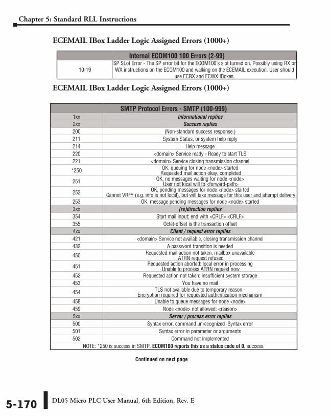
DL05 Micro PLC User Manual, 6th Edition, Rev. E5-170
Chapter 5: Standard RLL Instructions
ECEMAIL IBox Ladder Logic Assigned Errors (1000+)
ECEMAIL IBox Ladder Logic Assigned Errors (1000+)
SMTP Protocol Errors - SMTP (100-999)1xx Informational replies2xx Success replies200 (Non-standard success response.) 211 System Status, or system help reply214 Help message220 <domain> Service ready - Ready to start TLS221 <domain> Service closing transmission channel
*250 OK, queuing for node <node> started Requested mail action okay, completed
251 OK, no messages waiting for node <node> User not local will to <forward-path>
252 OK, pending messages for node <node> started Cannot VRFY (e.g. info is not local), but will take message for this user and attempt delivery
253 OK, message pending messages for node <node> started3xx (re)direction replies354 Start mail input; end with <CRLF> <CRLF>355 Octet-offset is the transaction offset4xx Client / request error replies421 <domain> Service not available, closing transmission channel432 A password transition is needed
450 Requested mail action not taken: mailbox unavailable ATRN request refused
451 Requested action aborted: local error in processing Unable to process ATRN request now
452 Requested action not taken: insufficient system storage453 You have no mail
454 TLS not available due to temporary reason - Encryption required for requested authentication mechanism
458 Unable to queue messages for node <node>459 Node <node> not allowed: <reason>5xx Server / process error replies500 Syntax error, command unrecognized Syntax error501 Syntax error in parameter or arguments502 Command not implemented
NOTE: *250 is success in SMTP. ECOM100 reports this as a status code of 0, success.
Continued on next page
Internal ECOM100 100 Errors (2-99)
10-19SP SLot Error - The SP error bit for the ECOM100’s slot turned on. Possibly using RX or WX instructions on the ECOM100 and walking on the ECEMAIL execution. User should
use ECRX and ECWX IBoxes.
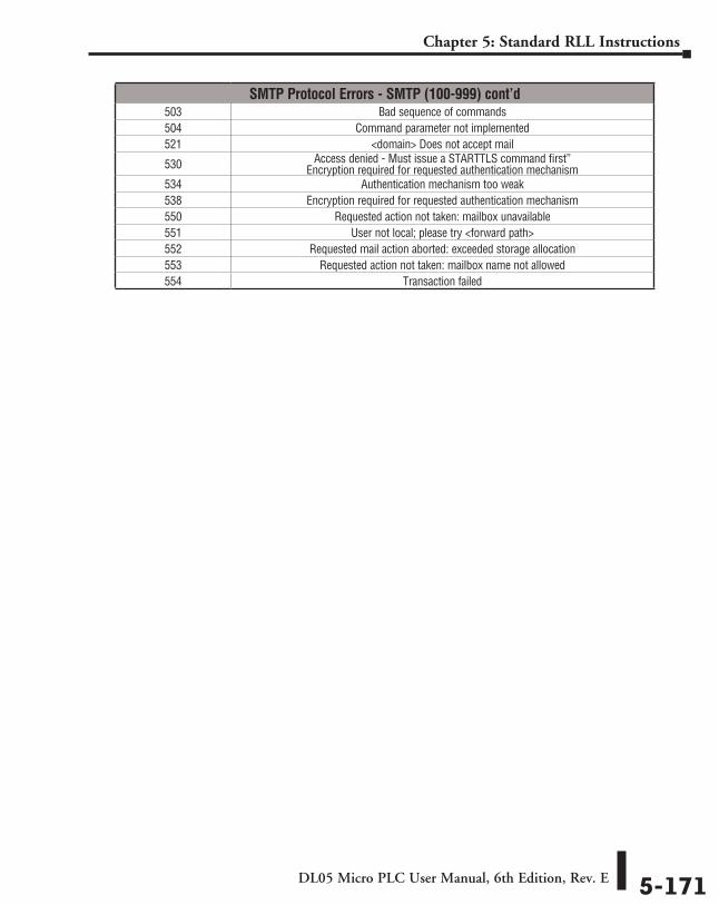
DL05 Micro PLC User Manual, 6th Edition, Rev. E 5-171
Chapter 5: Standard RLL Instructions
SMTP Protocol Errors - SMTP (100-999) cont’d503 Bad sequence of commands504 Command parameter not implemented521 <domain> Does not accept mail
530 Access denied - Must issue a STARTTLS command first” Encryption required for requested authentication mechanism
534 Authentication mechanism too weak538 Encryption required for requested authentication mechanism550 Requested action not taken: mailbox unavailable551 User not local; please try <forward path>552 Requested mail action aborted: exceeded storage allocation553 Requested action not taken: mailbox name not allowed554 Transaction failed
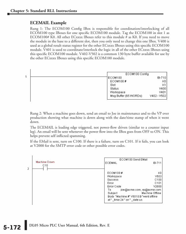
DL05 Micro PLC User Manual, 6th Edition, Rev. E5-172
Chapter 5: Standard RLL Instructions
Rung 2: When a machine goes down, send an email to Joe in maintenance and to the VP over production showing what machine is down along with the date/time stamp of when it went down.
The ECEMAIL is leading edge triggered, not power-flow driven (similar to a counter input leg). An email will be sent whenever the power flow into the IBox goes from OFF to ON. This helps prevent self inflicted spamming.
If the EMail is sent, turn on C100. If there is a failure, turn on C101. If it fails, you can look at V2000 for the SMTP error code or other possible error codes.
ECEMAIL ExampleRung 1: The ECOM100 Config IBox is responsible for coordination/interlocking of all ECOM100 type IBoxes for one specific ECOM100 module. Tag the ECOM100 in slot 1 as ECOM100# K0. All other ECxxxx IBoxes refer to this module # as K0. If you need to move the module in the base to a different slot, then you only need to change this one IBox. V400 is used as a global result status register for the other ECxxxx IBoxes using this specific ECOM100 module. V401 is used to coordinate/interlock the logic in all of the other ECxxxx IBoxes using this specific ECOM100 module. V402-V502 is a common 130 byte buffer available for use by the other ECxxxx IBoxes using this specific ECOM100 module.
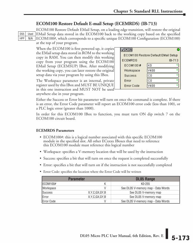
DL05 Micro PLC User Manual, 6th Edition, Rev. E 5-173
Chapter 5: Standard RLL Instructions
ECOM100 Restore Default E-mail Setup (ECEMRDS) (IB-713)ECOM100 Restore Default EMail Setup, on a leading edge transition, will restore the original EMail Setup data stored in the ECOM100 back to the working copy based on the specified ECOM100#, which corresponds to a specific unique ECOM100 Configuration (ECOM100) at the top of your program.
When the ECOM100 is first powered up, it copies the EMail setup data stored in ROM to the working copy in RAM. You can then modify this working copy from your program using the ECOM100 EMail Setup (ECEMSUP) IBox. After modifying the working copy, you can later restore the original setup data via your program by using this IBox.
The Workspace parameter is an internal, private register used by this IBox and MUST BE UNIQUE in this one instruction and MUST NOT be used anywhere else in your program.
Either the Success or Error bit parameter will turn on once the command is complete. If there is an error, the Error Code parameter will report an ECOM100 error code (less than 100), or a PLC logic error (greater than 1000).
In order for this ECOM100 IBox to function, you must turn ON dip switch 7 on the ECOM100 circuit board.
ECEMRDS Parameters
• ECOM100#: this is a logical number associated with this specific ECOM100 module in the specified slot. All other ECxxxx IBoxes that need to reference this ECOM100 module must reference this logical number
• Workspace: specifies a V-memory location that will be used by the instruction
• Success: specifies a bit that will turn on once the request is completed successfully
• Error: specifies a bit that will turn on if the instruction is not successfully completed
• Error Code: specifies the location where the Error Code will be written
DS5 Used
HPP N/A
Parameter DL05 RangeECOM100# ⸠⸠⸠⸠⸠⸠⸠⸠⸠⸠⸠⸠⸠⸠⸠⸠⸠⸠⸠⸠⸠⸠⸠⸠⸠⸠⸠⸠⸠⸠⸠⸠⸠⸠⸠⸠⸠⸠⸠⸠⸠⸠⸠⸠⸠⸠⸠⸠⸠⸠⸠⸠⸠⸠⸠⸠⸠⸠⸠⸠⸠⸠ K K0-255Workspace ⸠⸠⸠⸠⸠⸠⸠⸠⸠⸠⸠⸠⸠⸠⸠⸠⸠⸠⸠⸠⸠⸠⸠⸠⸠⸠⸠⸠⸠⸠⸠⸠⸠⸠⸠⸠⸠⸠⸠⸠⸠⸠⸠⸠⸠⸠⸠⸠⸠⸠⸠⸠⸠⸠⸠⸠⸠⸠⸠⸠⸠⸠ V See DL05 V-memory map - Data WordsSuccess ⸠⸠⸠⸠⸠⸠⸠⸠⸠⸠⸠⸠⸠⸠⸠⸠⸠⸠⸠⸠⸠⸠⸠⸠⸠⸠⸠⸠⸠⸠⸠⸠⸠⸠⸠⸠⸠⸠⸠⸠⸠⸠⸠⸠⸠ X,Y,C,GX,GY,B See DL05 V-memory mapError ⸠⸠⸠⸠⸠⸠⸠⸠⸠⸠⸠⸠⸠⸠⸠⸠⸠⸠⸠⸠⸠⸠⸠⸠⸠⸠⸠⸠⸠⸠⸠⸠⸠⸠⸠⸠⸠⸠⸠⸠⸠⸠⸠⸠⸠⸠⸠⸠⸠⸠ X,Y,C,GX,GY,B See DL05 V-memory mapError Code ⸠⸠⸠⸠⸠⸠⸠⸠⸠⸠⸠⸠⸠⸠⸠⸠⸠⸠⸠⸠⸠⸠⸠⸠⸠⸠⸠⸠⸠⸠⸠⸠⸠⸠⸠⸠⸠⸠⸠⸠⸠⸠⸠⸠⸠⸠⸠⸠⸠⸠⸠⸠⸠⸠⸠⸠⸠⸠⸠⸠⸠⸠⸠⸠⸠ V See DL05 V-memory map - Data Words
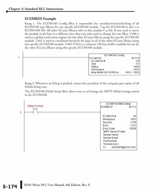
DL05 Micro PLC User Manual, 6th Edition, Rev. E5-174
Chapter 5: Standard RLL Instructions
ECEMRDS ExampleRung 1: The ECOM100 Config IBox is responsible for coordination/interlocking of all ECOM100 type IBoxes for one specific ECOM100 module. Tag the ECOM100 in slot 1 as ECOM100# K0. All other ECxxxx IBoxes refer to this module # as K0. If you need to move the module in the base to a different slot, then you only need to change this one IBox. V400 is used as a global result status register for the other ECxxxx IBoxes using this specific ECOM100 module. V401 is used to coordinate/interlock the logic in all of the other ECxxxx IBoxes using this specific ECOM100 module. V402-V502 is a common 130 byte buffer available for use by the other ECxxxx IBoxes using this specific ECOM100 module.
Rung 2: Whenever an EStop is pushed, ensure that president of the company gets copies of all EMails being sent.
The ECOM100 EMail Setup IBox allows you to set/change the SMTP EMail settings stored in the ECOM100.
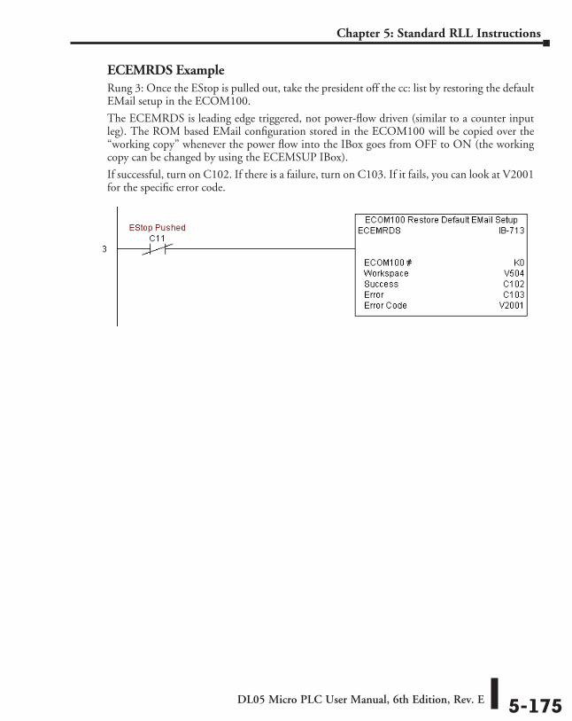
DL05 Micro PLC User Manual, 6th Edition, Rev. E 5-175
Chapter 5: Standard RLL Instructions
ECEMRDS ExampleRung 3: Once the EStop is pulled out, take the president off the cc: list by restoring the default EMail setup in the ECOM100.
The ECEMRDS is leading edge triggered, not power-flow driven (similar to a counter input leg). The ROM based EMail configuration stored in the ECOM100 will be copied over the “working copy” whenever the power flow into the IBox goes from OFF to ON (the working copy can be changed by using the ECEMSUP IBox).
If successful, turn on C102. If there is a failure, turn on C103. If it fails, you can look at V2001 for the specific error code.
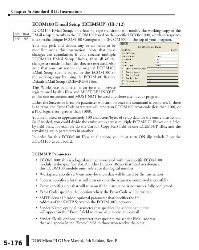
DL05 Micro PLC User Manual, 6th Edition, Rev. E5-176
Chapter 5: Standard RLL Instructions
ECOM100 E-mail Setup (ECEMSUP) (IB-712)ECOM100 EMail Setup, on a leading edge transition, will modify the working copy of the EMail setup currently in the ECOM100 based on the specified ECOM100#, which corresponds to a specific unique ECOM100 Configuration (ECOM100) at the top of your program.
You may pick and choose any or all fields to be modified using this instruction. Note that these changes are cumulative: if you execute multiple ECOM100 EMail Setup IBoxes, then all of the changes are made in the order they are executed. Also note that you can restore the original ECOM100 EMail Setup that is stored in the ECOM100 to the working copy by using the ECOM100 Restore Default EMail Setup (ECEMRDS) IBox.
The Workspace parameter is an internal, private register used by this IBox and MUST BE UNIQUE in this one instruction and MUST NOT be used anywhere else in your program.
Either the Success or Error bit parameter will turn on once the command is complete. If there is an error, the Error Code parameter will report an ECOM100 error code (less than 100), or a PLC logic error (greater than 1000).
You are limited to approximately 100 characters/bytes of setup data for the entire instruction. So if needed, you could divide the entire setup across multiple ECEMSUP IBoxes on a field-by-field basis, for example do the Carbon Copy (cc:) field in one ECEMSUP IBox and the remaining setup parameters in another.
In order for this ECOM100 IBox to function, you must turn ON dip switch 7 on the ECOM100 circuit board.
ECEMSUP Parameters
• ECOM100#: this is a logical number associated with this specific ECOM100 module in the specified slot. All other ECxxxx IBoxes that need to reference this ECOM100 module must reference this logical number
• Workspace: specifies a V-memory location that will be used by the instruction
• Success: specifies a bit that will turn on once the request is completed successfully
• Error: specifies a bit that will turn on if the instruction is not successfully completed
• Error Code: specifies the location where the Error Code will be written
• SMTP Server IP Addr: optional parameter that specifies the IP Address of the SMTP Server on the ECOM100’s network
• Sender Name: optional parameter that specifies the sender name that will appear in the “From:” field to those who receive the e-mail
• Sender EMail: optional parameter that specifies the sender EMail address that will appear in the “From:” field to those who receive the e-mail
DS5 Used
HPP N/A
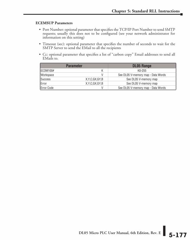
DL05 Micro PLC User Manual, 6th Edition, Rev. E 5-177
Chapter 5: Standard RLL Instructions
ECEMSUP Parameters
• Port Number: optional parameter that specifies the TCP/IP Port Number to send SMTP requests; usually this does not to be configured (see your network administrator for information on this setting)
• Timeout (sec): optional parameter that specifies the number of seconds to wait for the SMTP Server to send the EMail to all the recipients
• Cc: optional parameter that specifies a list of “carbon copy” Email addresses to send all EMails to.
Parameter DL05 RangeECOM100# ⸠⸠⸠⸠⸠⸠⸠⸠⸠⸠⸠⸠⸠⸠⸠⸠⸠⸠⸠⸠⸠⸠⸠⸠⸠⸠⸠⸠⸠⸠⸠⸠⸠⸠⸠⸠⸠⸠⸠⸠⸠⸠⸠⸠⸠⸠⸠⸠⸠⸠⸠⸠⸠⸠⸠⸠⸠⸠⸠⸠⸠⸠ K K0-255Workspace ⸠⸠⸠⸠⸠⸠⸠⸠⸠⸠⸠⸠⸠⸠⸠⸠⸠⸠⸠⸠⸠⸠⸠⸠⸠⸠⸠⸠⸠⸠⸠⸠⸠⸠⸠⸠⸠⸠⸠⸠⸠⸠⸠⸠⸠⸠⸠⸠⸠⸠⸠⸠⸠⸠⸠⸠⸠⸠⸠⸠⸠⸠ V See DL05 V-memory map - Data WordsSuccess ⸠⸠⸠⸠⸠⸠⸠⸠⸠⸠⸠⸠⸠⸠⸠⸠⸠⸠⸠⸠⸠⸠⸠⸠⸠⸠⸠⸠⸠⸠⸠⸠⸠⸠⸠⸠⸠⸠⸠⸠⸠⸠⸠⸠⸠ X,Y,C,GX,GY,B See DL05 V-memory mapError ⸠⸠⸠⸠⸠⸠⸠⸠⸠⸠⸠⸠⸠⸠⸠⸠⸠⸠⸠⸠⸠⸠⸠⸠⸠⸠⸠⸠⸠⸠⸠⸠⸠⸠⸠⸠⸠⸠⸠⸠⸠⸠⸠⸠⸠⸠⸠⸠⸠⸠ X,Y,C,GX,GY,B See DL05 V-memory mapError Code ⸠⸠⸠⸠⸠⸠⸠⸠⸠⸠⸠⸠⸠⸠⸠⸠⸠⸠⸠⸠⸠⸠⸠⸠⸠⸠⸠⸠⸠⸠⸠⸠⸠⸠⸠⸠⸠⸠⸠⸠⸠⸠⸠⸠⸠⸠⸠⸠⸠⸠⸠⸠⸠⸠⸠⸠⸠⸠⸠⸠⸠⸠⸠⸠⸠ V See DL05 V-memory map - Data Words
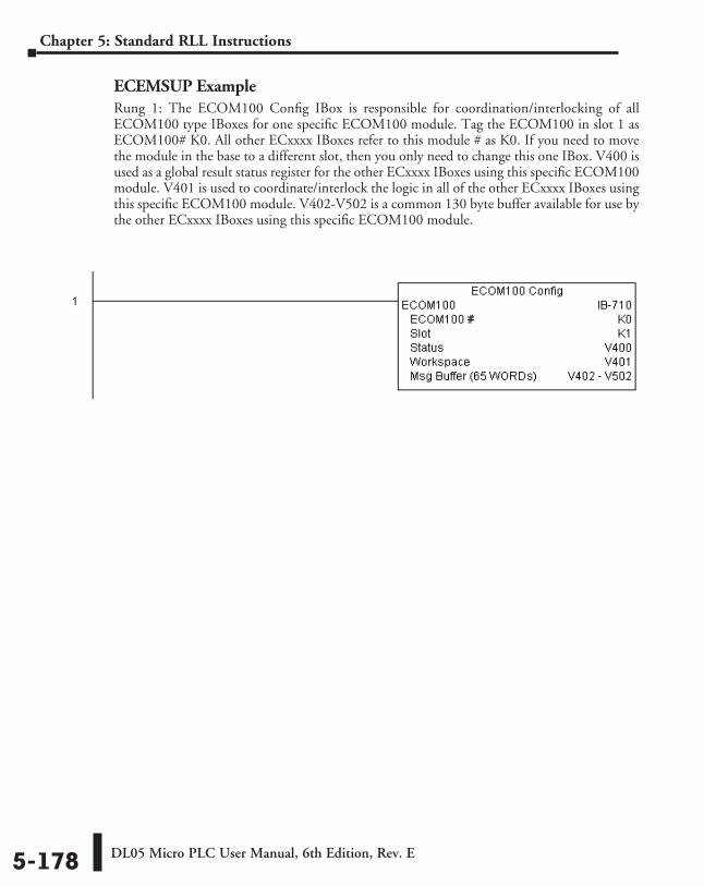
DL05 Micro PLC User Manual, 6th Edition, Rev. E5-178
Chapter 5: Standard RLL Instructions
ECEMSUP ExampleRung 1: The ECOM100 Config IBox is responsible for coordination/interlocking of all ECOM100 type IBoxes for one specific ECOM100 module. Tag the ECOM100 in slot 1 as ECOM100# K0. All other ECxxxx IBoxes refer to this module # as K0. If you need to move the module in the base to a different slot, then you only need to change this one IBox. V400 is used as a global result status register for the other ECxxxx IBoxes using this specific ECOM100 module. V401 is used to coordinate/interlock the logic in all of the other ECxxxx IBoxes using this specific ECOM100 module. V402-V502 is a common 130 byte buffer available for use by the other ECxxxx IBoxes using this specific ECOM100 module.
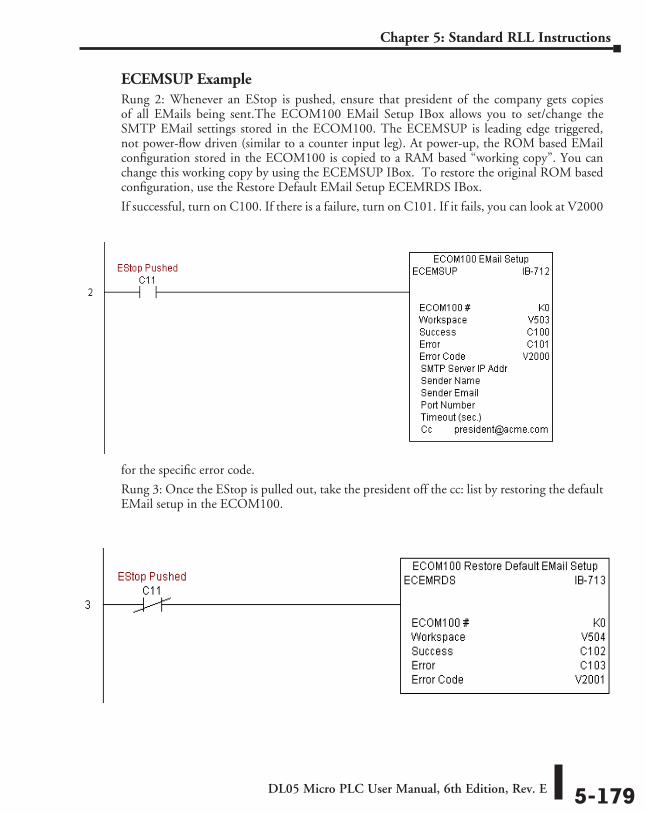
DL05 Micro PLC User Manual, 6th Edition, Rev. E 5-179
Chapter 5: Standard RLL Instructions
ECEMSUP ExampleRung 2: Whenever an EStop is pushed, ensure that president of the company gets copies of all EMails being sent.The ECOM100 EMail Setup IBox allows you to set/change the SMTP EMail settings stored in the ECOM100. The ECEMSUP is leading edge triggered, not power-flow driven (similar to a counter input leg). At power-up, the ROM based EMail configuration stored in the ECOM100 is copied to a RAM based “working copy”. You can change this working copy by using the ECEMSUP IBox. To restore the original ROM based configuration, use the Restore Default EMail Setup ECEMRDS IBox.
If successful, turn on C100. If there is a failure, turn on C101. If it fails, you can look at V2000
for the specific error code.
Rung 3: Once the EStop is pulled out, take the president off the cc: list by restoring the default EMail setup in the ECOM100.
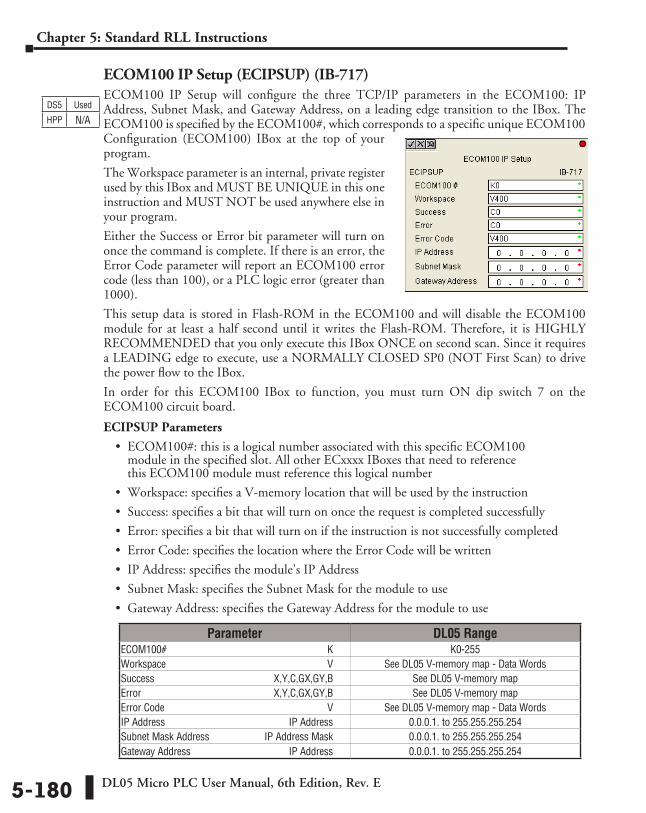
DL05 Micro PLC User Manual, 6th Edition, Rev. E5-180
Chapter 5: Standard RLL Instructions
ECOM100 IP Setup (ECIPSUP) (IB-717)ECOM100 IP Setup will configure the three TCP/IP parameters in the ECOM100: IP Address, Subnet Mask, and Gateway Address, on a leading edge transition to the IBox. The ECOM100 is specified by the ECOM100#, which corresponds to a specific unique ECOM100 Configuration (ECOM100) IBox at the top of your program.
The Workspace parameter is an internal, private register used by this IBox and MUST BE UNIQUE in this one instruction and MUST NOT be used anywhere else in your program.
Either the Success or Error bit parameter will turn on once the command is complete. If there is an error, the Error Code parameter will report an ECOM100 error code (less than 100), or a PLC logic error (greater than 1000).
This setup data is stored in Flash-ROM in the ECOM100 and will disable the ECOM100 module for at least a half second until it writes the Flash-ROM. Therefore, it is HIGHLY RECOMMENDED that you only execute this IBox ONCE on second scan. Since it requires a LEADING edge to execute, use a NORMALLY CLOSED SP0 (NOT First Scan) to drive the power flow to the IBox.
In order for this ECOM100 IBox to function, you must turn ON dip switch 7 on the ECOM100 circuit board.
ECIPSUP Parameters
• ECOM100#: this is a logical number associated with this specific ECOM100 module in the specified slot. All other ECxxxx IBoxes that need to reference this ECOM100 module must reference this logical number
• Workspace: specifies a V-memory location that will be used by the instruction
• Success: specifies a bit that will turn on once the request is completed successfully
• Error: specifies a bit that will turn on if the instruction is not successfully completed
• Error Code: specifies the location where the Error Code will be written
• IP Address: specifies the module’s IP Address
• Subnet Mask: specifies the Subnet Mask for the module to use
• Gateway Address: specifies the Gateway Address for the module to use
DS5 Used
HPP N/A
Parameter DL05 RangeECOM100# ⸠⸠⸠⸠⸠⸠⸠⸠⸠⸠⸠⸠⸠⸠⸠⸠⸠⸠⸠⸠⸠⸠⸠⸠⸠⸠⸠⸠⸠⸠⸠⸠⸠⸠⸠⸠⸠⸠⸠⸠⸠⸠⸠⸠⸠⸠⸠⸠⸠⸠⸠⸠⸠⸠⸠⸠⸠⸠⸠⸠⸠⸠ K K0-255Workspace ⸠⸠⸠⸠⸠⸠⸠⸠⸠⸠⸠⸠⸠⸠⸠⸠⸠⸠⸠⸠⸠⸠⸠⸠⸠⸠⸠⸠⸠⸠⸠⸠⸠⸠⸠⸠⸠⸠⸠⸠⸠⸠⸠⸠⸠⸠⸠⸠⸠⸠⸠⸠⸠⸠⸠⸠⸠⸠⸠⸠⸠⸠ V See DL05 V-memory map - Data WordsSuccess ⸠⸠⸠⸠⸠⸠⸠⸠⸠⸠⸠⸠⸠⸠⸠⸠⸠⸠⸠⸠⸠⸠⸠⸠⸠⸠⸠⸠⸠⸠⸠⸠⸠⸠⸠⸠⸠⸠⸠⸠⸠⸠⸠⸠⸠ X,Y,C,GX,GY,B See DL05 V-memory mapError ⸠⸠⸠⸠⸠⸠⸠⸠⸠⸠⸠⸠⸠⸠⸠⸠⸠⸠⸠⸠⸠⸠⸠⸠⸠⸠⸠⸠⸠⸠⸠⸠⸠⸠⸠⸠⸠⸠⸠⸠⸠⸠⸠⸠⸠⸠⸠⸠⸠⸠ X,Y,C,GX,GY,B See DL05 V-memory mapError Code ⸠⸠⸠⸠⸠⸠⸠⸠⸠⸠⸠⸠⸠⸠⸠⸠⸠⸠⸠⸠⸠⸠⸠⸠⸠⸠⸠⸠⸠⸠⸠⸠⸠⸠⸠⸠⸠⸠⸠⸠⸠⸠⸠⸠⸠⸠⸠⸠⸠⸠⸠⸠⸠⸠⸠⸠⸠⸠⸠⸠⸠⸠⸠⸠⸠ V See DL05 V-memory map - Data WordsIP Address ⸠⸠⸠⸠⸠⸠⸠⸠⸠⸠⸠⸠⸠⸠⸠⸠⸠⸠⸠⸠⸠⸠⸠⸠⸠⸠⸠⸠⸠⸠⸠⸠⸠⸠⸠⸠⸠⸠⸠⸠⸠⸠⸠⸠⸠⸠⸠⸠⸠⸠IP Address 0.0.0.1. to 255.255.255.254Subnet Mask Address ⸠⸠⸠⸠⸠⸠⸠⸠⸠⸠⸠⸠⸠⸠⸠⸠⸠⸠⸠⸠⸠⸠IP Address Mask 0.0.0.1. to 255.255.255.254Gateway Address ⸠⸠⸠⸠⸠⸠⸠⸠⸠⸠⸠⸠⸠⸠⸠⸠⸠⸠⸠⸠⸠⸠⸠⸠⸠⸠⸠⸠⸠⸠⸠⸠⸠⸠⸠⸠⸠⸠⸠IP Address 0.0.0.1. to 255.255.255.254
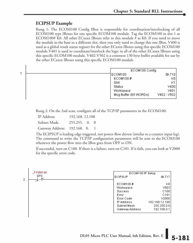
DL05 Micro PLC User Manual, 6th Edition, Rev. E 5-181
Chapter 5: Standard RLL Instructions
ECIPSUP ExampleRung 1: The ECOM100 Config IBox is responsible for coordination/interlocking of all ECOM100 type IBoxes for one specific ECOM100 module. Tag the ECOM100 in slot 1 as ECOM100# K0. All other ECxxxx IBoxes refer to this module # as K0. If you need to move the module in the base to a different slot, then you only need to change this one IBox. V400 is used as a global result status register for the other ECxxxx IBoxes using this specific ECOM100 module.V401 is used to coordinate/interlock the logic in all of the other ECxxxx IBoxes using this specific ECOM100 module. V402-V502 is a common 130 byte buffer available for use by the other ECxxxx IBoxes using this specific ECOM100 module.
Rung 2: On the 2nd scan, configure all of the TCP/IP parameters in the ECOM100:
IP Address: 192.168. 12.100
Subnet Mask: 255.255. 0. 0
Gateway Address: 192.168. 0. 1
The ECIPSUP is leading edge triggered, not power-flow driven (similar to a counter input leg). The command to write the TCP/IP configuration parameters will be sent to the ECOM100 whenever the power flow into the IBox goes from OFF to ON.
If successful, turn on C100. If there is a failure, turn on C101. If it fails, you can look at V2000 for the specific error code.
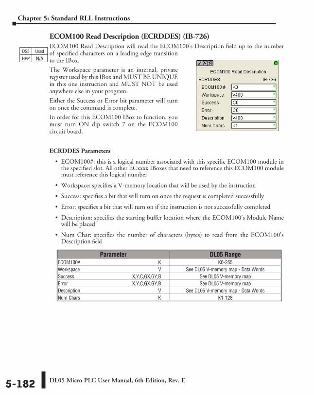
DL05 Micro PLC User Manual, 6th Edition, Rev. E5-182
Chapter 5: Standard RLL Instructions
ECOM100 Read Description (ECRDDES) (IB-726)ECOM100 Read Description will read the ECOM100’s Description field up to the number of specified characters on a leading edge transition to the IBox.
The Workspace parameter is an internal, private register used by this IBox and MUST BE UNIQUE in this one instruction and MUST NOT be used anywhere else in your program.
Either the Success or Error bit parameter will turn on once the command is complete.
In order for this ECOM100 IBox to function, you must turn ON dip switch 7 on the ECOM100 circuit board.
ECRDDES Parameters
• ECOM100#: this is a logical number associated with this specific ECOM100 module in the specified slot. All other ECxxxx IBoxes that need to reference this ECOM100 module must reference this logical number
• Workspace: specifies a V-memory location that will be used by the instruction
• Success: specifies a bit that will turn on once the request is completed successfully
• Error: specifies a bit that will turn on if the instruction is not successfully completed
• Description: specifies the starting buffer location where the ECOM100’s Module Name will be placed
• Num Char: specifies the number of characters (bytes) to read from the ECOM100’s Description field
DS5 Used
HPP N/A
Parameter DL05 RangeECOM100# ⸠⸠⸠⸠⸠⸠⸠⸠⸠⸠⸠⸠⸠⸠⸠⸠⸠⸠⸠⸠⸠⸠⸠⸠⸠⸠⸠⸠⸠⸠⸠⸠⸠⸠⸠⸠⸠⸠⸠⸠⸠⸠⸠⸠⸠⸠⸠⸠⸠⸠⸠⸠⸠⸠⸠⸠⸠⸠⸠⸠⸠⸠ K K0-255Workspace ⸠⸠⸠⸠⸠⸠⸠⸠⸠⸠⸠⸠⸠⸠⸠⸠⸠⸠⸠⸠⸠⸠⸠⸠⸠⸠⸠⸠⸠⸠⸠⸠⸠⸠⸠⸠⸠⸠⸠⸠⸠⸠⸠⸠⸠⸠⸠⸠⸠⸠⸠⸠⸠⸠⸠⸠⸠⸠⸠⸠⸠⸠ V See DL05 V-memory map - Data WordsSuccess ⸠⸠⸠⸠⸠⸠⸠⸠⸠⸠⸠⸠⸠⸠⸠⸠⸠⸠⸠⸠⸠⸠⸠⸠⸠⸠⸠⸠⸠⸠⸠⸠⸠⸠⸠⸠⸠⸠⸠⸠⸠⸠⸠⸠⸠ X,Y,C,GX,GY,B See DL05 V-memory mapError ⸠⸠⸠⸠⸠⸠⸠⸠⸠⸠⸠⸠⸠⸠⸠⸠⸠⸠⸠⸠⸠⸠⸠⸠⸠⸠⸠⸠⸠⸠⸠⸠⸠⸠⸠⸠⸠⸠⸠⸠⸠⸠⸠⸠⸠⸠⸠⸠⸠⸠ X,Y,C,GX,GY,B See DL05 V-memory mapDescription ⸠⸠⸠⸠⸠⸠⸠⸠⸠⸠⸠⸠⸠⸠⸠⸠⸠⸠⸠⸠⸠⸠⸠⸠⸠⸠⸠⸠⸠⸠⸠⸠⸠⸠⸠⸠⸠⸠⸠⸠⸠⸠⸠⸠⸠⸠⸠⸠⸠⸠⸠⸠⸠⸠⸠⸠⸠⸠⸠⸠⸠⸠ V See DL05 V-memory map - Data WordsNum Chars ⸠⸠⸠⸠⸠⸠⸠⸠⸠⸠⸠⸠⸠⸠⸠⸠⸠⸠⸠⸠⸠⸠⸠⸠⸠⸠⸠⸠⸠⸠⸠⸠⸠⸠⸠⸠⸠⸠⸠⸠⸠⸠⸠⸠⸠⸠⸠⸠⸠⸠⸠⸠⸠⸠⸠⸠⸠⸠⸠⸠⸠⸠⸠⸠ K K1-128
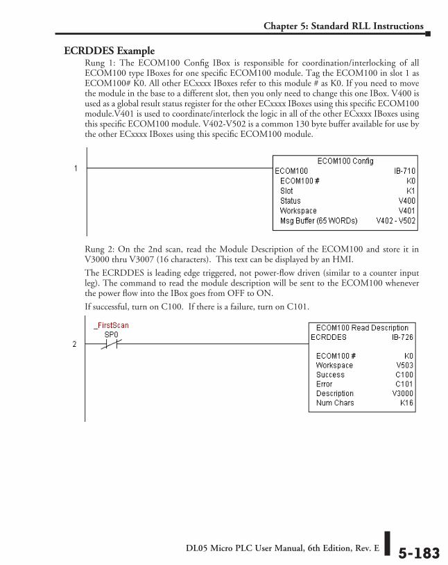
DL05 Micro PLC User Manual, 6th Edition, Rev. E 5-183
Chapter 5: Standard RLL Instructions
ECRDDES ExampleRung 1: The ECOM100 Config IBox is responsible for coordination/interlocking of all ECOM100 type IBoxes for one specific ECOM100 module. Tag the ECOM100 in slot 1 as ECOM100# K0. All other ECxxxx IBoxes refer to this module # as K0. If you need to move the module in the base to a different slot, then you only need to change this one IBox. V400 is used as a global result status register for the other ECxxxx IBoxes using this specific ECOM100 module.V401 is used to coordinate/interlock the logic in all of the other ECxxxx IBoxes using this specific ECOM100 module. V402-V502 is a common 130 byte buffer available for use by the other ECxxxx IBoxes using this specific ECOM100 module.
Rung 2: On the 2nd scan, read the Module Description of the ECOM100 and store it in V3000 thru V3007 (16 characters). This text can be displayed by an HMI.
The ECRDDES is leading edge triggered, not power-flow driven (similar to a counter input leg). The command to read the module description will be sent to the ECOM100 whenever the power flow into the IBox goes from OFF to ON.
If successful, turn on C100. If there is a failure, turn on C101.
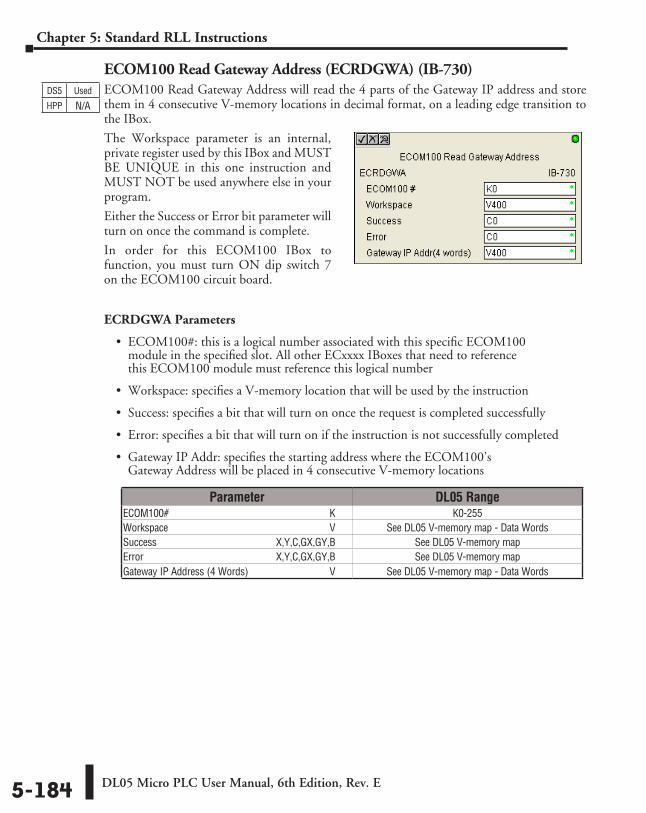
DL05 Micro PLC User Manual, 6th Edition, Rev. E5-184
Chapter 5: Standard RLL Instructions
ECOM100 Read Gateway Address (ECRDGWA) (IB-730)ECOM100 Read Gateway Address will read the 4 parts of the Gateway IP address and store them in 4 consecutive V-memory locations in decimal format, on a leading edge transition to the IBox.
The Workspace parameter is an internal, private register used by this IBox and MUST BE UNIQUE in this one instruction and MUST NOT be used anywhere else in your program.
Either the Success or Error bit parameter will turn on once the command is complete.
In order for this ECOM100 IBox to function, you must turn ON dip switch 7 on the ECOM100 circuit board.
ECRDGWA Parameters
• ECOM100#: this is a logical number associated with this specific ECOM100 module in the specified slot. All other ECxxxx IBoxes that need to reference this ECOM100 module must reference this logical number
• Workspace: specifies a V-memory location that will be used by the instruction
• Success: specifies a bit that will turn on once the request is completed successfully
• Error: specifies a bit that will turn on if the instruction is not successfully completed
• Gateway IP Addr: specifies the starting address where the ECOM100’s Gateway Address will be placed in 4 consecutive V-memory locations
DS5 Used
HPP N/A
Parameter DL05 RangeECOM100# ⸠⸠⸠⸠⸠⸠⸠⸠⸠⸠⸠⸠⸠⸠⸠⸠⸠⸠⸠⸠⸠⸠⸠⸠⸠⸠⸠⸠⸠⸠⸠⸠⸠⸠⸠⸠⸠⸠⸠⸠⸠⸠⸠⸠⸠⸠⸠⸠⸠⸠⸠⸠⸠⸠⸠⸠⸠⸠⸠⸠⸠⸠ K K0-255Workspace ⸠⸠⸠⸠⸠⸠⸠⸠⸠⸠⸠⸠⸠⸠⸠⸠⸠⸠⸠⸠⸠⸠⸠⸠⸠⸠⸠⸠⸠⸠⸠⸠⸠⸠⸠⸠⸠⸠⸠⸠⸠⸠⸠⸠⸠⸠⸠⸠⸠⸠⸠⸠⸠⸠⸠⸠⸠⸠⸠⸠⸠⸠ V See DL05 V-memory map - Data WordsSuccess ⸠⸠⸠⸠⸠⸠⸠⸠⸠⸠⸠⸠⸠⸠⸠⸠⸠⸠⸠⸠⸠⸠⸠⸠⸠⸠⸠⸠⸠⸠⸠⸠⸠⸠⸠⸠⸠⸠⸠⸠⸠⸠⸠⸠⸠ X,Y,C,GX,GY,B See DL05 V-memory mapError ⸠⸠⸠⸠⸠⸠⸠⸠⸠⸠⸠⸠⸠⸠⸠⸠⸠⸠⸠⸠⸠⸠⸠⸠⸠⸠⸠⸠⸠⸠⸠⸠⸠⸠⸠⸠⸠⸠⸠⸠⸠⸠⸠⸠⸠⸠⸠⸠⸠⸠ X,Y,C,GX,GY,B See DL05 V-memory mapGateway IP Address (4 Words) ⸠⸠⸠⸠⸠⸠⸠⸠⸠⸠⸠⸠⸠⸠⸠⸠⸠⸠⸠⸠⸠⸠⸠⸠⸠⸠⸠⸠⸠⸠⸠⸠ V See DL05 V-memory map - Data Words
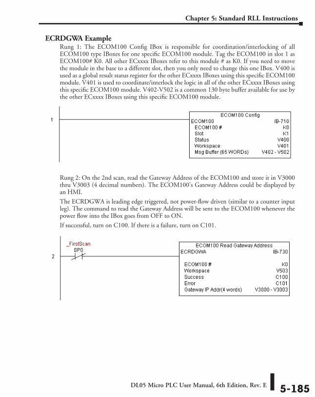
DL05 Micro PLC User Manual, 6th Edition, Rev. E 5-185
Chapter 5: Standard RLL Instructions
ECRDGWA ExampleRung 1: The ECOM100 Config IBox is responsible for coordination/interlocking of all ECOM100 type IBoxes for one specific ECOM100 module. Tag the ECOM100 in slot 1 as ECOM100# K0. All other ECxxxx IBoxes refer to this module # as K0. If you need to move the module in the base to a different slot, then you only need to change this one IBox. V400 is used as a global result status register for the other ECxxxx IBoxes using this specific ECOM100 module. V401 is used to coordinate/interlock the logic in all of the other ECxxxx IBoxes using this specific ECOM100 module. V402-V502 is a common 130 byte buffer available for use by the other ECxxxx IBoxes using this specific ECOM100 module.
Rung 2: On the 2nd scan, read the Gateway Address of the ECOM100 and store it in V3000 thru V3003 (4 decimal numbers). The ECOM100’s Gateway Address could be displayed by an HMI.
The ECRDGWA is leading edge triggered, not power-flow driven (similar to a counter input leg). The command to read the Gateway Address will be sent to the ECOM100 whenever the power flow into the IBox goes from OFF to ON.
If successful, turn on C100. If there is a failure, turn on C101.
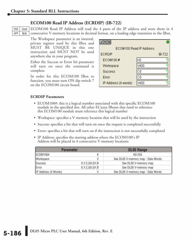
DL05 Micro PLC User Manual, 6th Edition, Rev. E5-186
Chapter 5: Standard RLL Instructions
ECOM100 Read IP Address (ECRDIP) (IB-722)ECOM100 Read IP Address will read the 4 parts of the IP address and store them in 4 consecutive V-memory locations in decimal format, on a leading edge transition to the IBox.
The Workspace parameter is an internal, private register used by this IBox and MUST BE UNIQUE in this one instruction and MUST NOT be used anywhere else in your program.
Either the Success or Error bit parameter will turn on once the command is complete.
In order for this ECOM100 IBox to function, you must turn ON dip switch 7 on the ECOM100 circuit board.
ECRDIP Parameters
• ECOM100#: this is a logical number associated with this specific ECOM100 module in the specified slot. All other ECxxxx IBoxes that need to reference this ECOM100 module must reference this logical number
• Workspace: specifies a V-memory location that will be used by the instruction
• Success: specifies a bit that will turn on once the request is completed successfully
• Error: specifies a bit that will turn on if the instruction is not successfully completed
• IP Address: specifies the starting address where the ECOM100’s IP Address will be placed in 4 consecutive V-memory locations
DS5 Used
HPP N/A
Parameter DL05 RangeECOM100# ⸠⸠⸠⸠⸠⸠⸠⸠⸠⸠⸠⸠⸠⸠⸠⸠⸠⸠⸠⸠⸠⸠⸠⸠⸠⸠⸠⸠⸠⸠⸠⸠⸠⸠⸠⸠⸠⸠⸠⸠⸠⸠⸠⸠⸠⸠⸠⸠⸠⸠⸠⸠⸠⸠⸠⸠⸠⸠⸠⸠⸠⸠ K K0-255Workspace ⸠⸠⸠⸠⸠⸠⸠⸠⸠⸠⸠⸠⸠⸠⸠⸠⸠⸠⸠⸠⸠⸠⸠⸠⸠⸠⸠⸠⸠⸠⸠⸠⸠⸠⸠⸠⸠⸠⸠⸠⸠⸠⸠⸠⸠⸠⸠⸠⸠⸠⸠⸠⸠⸠⸠⸠⸠⸠⸠⸠⸠⸠ V See DL05 V-memory map - Data WordsSuccess ⸠⸠⸠⸠⸠⸠⸠⸠⸠⸠⸠⸠⸠⸠⸠⸠⸠⸠⸠⸠⸠⸠⸠⸠⸠⸠⸠⸠⸠⸠⸠⸠⸠⸠⸠⸠⸠⸠⸠⸠⸠⸠⸠⸠⸠ X,Y,C,GX,GY,B See DL05 V-memory mapError ⸠⸠⸠⸠⸠⸠⸠⸠⸠⸠⸠⸠⸠⸠⸠⸠⸠⸠⸠⸠⸠⸠⸠⸠⸠⸠⸠⸠⸠⸠⸠⸠⸠⸠⸠⸠⸠⸠⸠⸠⸠⸠⸠⸠⸠⸠⸠⸠⸠⸠ X,Y,C,GX,GY,B See DL05 V-memory mapIP Address (4 Words) ⸠⸠⸠⸠⸠⸠⸠⸠⸠⸠⸠⸠⸠⸠⸠⸠⸠⸠⸠⸠⸠⸠⸠⸠⸠⸠⸠⸠⸠⸠⸠⸠⸠⸠⸠⸠⸠⸠⸠⸠⸠⸠⸠⸠⸠⸠⸠ V See DL05 V-memory map - Data Words
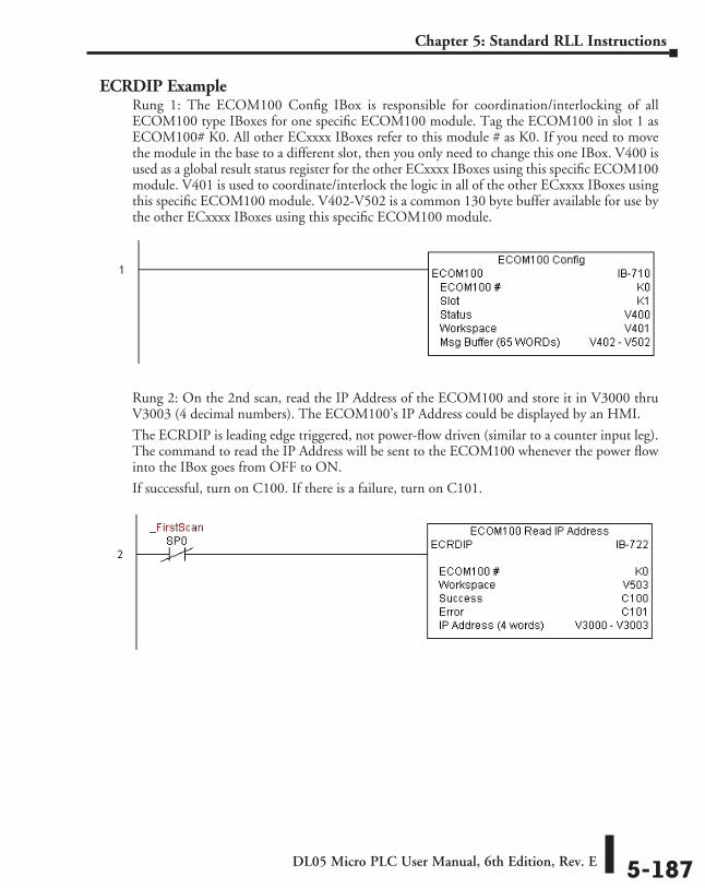
DL05 Micro PLC User Manual, 6th Edition, Rev. E 5-187
Chapter 5: Standard RLL Instructions
ECRDIP ExampleRung 1: The ECOM100 Config IBox is responsible for coordination/interlocking of all ECOM100 type IBoxes for one specific ECOM100 module. Tag the ECOM100 in slot 1 as ECOM100# K0. All other ECxxxx IBoxes refer to this module # as K0. If you need to move the module in the base to a different slot, then you only need to change this one IBox. V400 is used as a global result status register for the other ECxxxx IBoxes using this specific ECOM100 module. V401 is used to coordinate/interlock the logic in all of the other ECxxxx IBoxes using this specific ECOM100 module. V402-V502 is a common 130 byte buffer available for use by the other ECxxxx IBoxes using this specific ECOM100 module.
Rung 2: On the 2nd scan, read the IP Address of the ECOM100 and store it in V3000 thru V3003 (4 decimal numbers). The ECOM100’s IP Address could be displayed by an HMI.
The ECRDIP is leading edge triggered, not power-flow driven (similar to a counter input leg). The command to read the IP Address will be sent to the ECOM100 whenever the power flow into the IBox goes from OFF to ON.
If successful, turn on C100. If there is a failure, turn on C101.
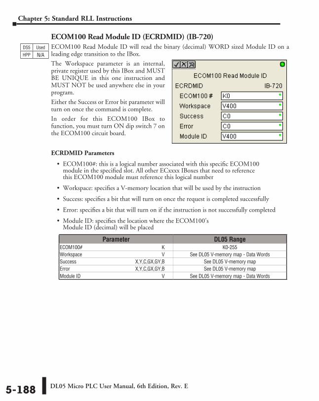
DL05 Micro PLC User Manual, 6th Edition, Rev. E5-188
Chapter 5: Standard RLL Instructions
ECOM100 Read Module ID (ECRDMID) (IB-720)ECOM100 Read Module ID will read the binary (decimal) WORD sized Module ID on a leading edge transition to the IBox.
The Workspace parameter is an internal, private register used by this IBox and MUST BE UNIQUE in this one instruction and MUST NOT be used anywhere else in your program.
Either the Success or Error bit parameter will turn on once the command is complete.
In order for this ECOM100 IBox to function, you must turn ON dip switch 7 on the ECOM100 circuit board.
ECRDMID Parameters
• ECOM100#: this is a logical number associated with this specific ECOM100 module in the specified slot. All other ECxxxx IBoxes that need to reference this ECOM100 module must reference this logical number
• Workspace: specifies a V-memory location that will be used by the instruction
• Success: specifies a bit that will turn on once the request is completed successfully
• Error: specifies a bit that will turn on if the instruction is not successfully completed
• Module ID: specifies the location where the ECOM100’s Module ID (decimal) will be placed
DS5 Used
HPP N/A
Parameter DL05 RangeECOM100# ⸠⸠⸠⸠⸠⸠⸠⸠⸠⸠⸠⸠⸠⸠⸠⸠⸠⸠⸠⸠⸠⸠⸠⸠⸠⸠⸠⸠⸠⸠⸠⸠⸠⸠⸠⸠⸠⸠⸠⸠⸠⸠⸠⸠⸠⸠⸠⸠⸠⸠⸠⸠⸠⸠⸠⸠⸠⸠⸠⸠⸠⸠ K K0-255Workspace ⸠⸠⸠⸠⸠⸠⸠⸠⸠⸠⸠⸠⸠⸠⸠⸠⸠⸠⸠⸠⸠⸠⸠⸠⸠⸠⸠⸠⸠⸠⸠⸠⸠⸠⸠⸠⸠⸠⸠⸠⸠⸠⸠⸠⸠⸠⸠⸠⸠⸠⸠⸠⸠⸠⸠⸠⸠⸠⸠⸠⸠⸠ V See DL05 V-memory map - Data WordsSuccess ⸠⸠⸠⸠⸠⸠⸠⸠⸠⸠⸠⸠⸠⸠⸠⸠⸠⸠⸠⸠⸠⸠⸠⸠⸠⸠⸠⸠⸠⸠⸠⸠⸠⸠⸠⸠⸠⸠⸠⸠⸠⸠⸠⸠⸠ X,Y,C,GX,GY,B See DL05 V-memory mapError ⸠⸠⸠⸠⸠⸠⸠⸠⸠⸠⸠⸠⸠⸠⸠⸠⸠⸠⸠⸠⸠⸠⸠⸠⸠⸠⸠⸠⸠⸠⸠⸠⸠⸠⸠⸠⸠⸠⸠⸠⸠⸠⸠⸠⸠⸠⸠⸠⸠⸠ X,Y,C,GX,GY,B See DL05 V-memory mapModule ID⸠⸠⸠⸠⸠⸠⸠⸠⸠⸠⸠⸠⸠⸠⸠⸠⸠⸠⸠⸠⸠⸠⸠⸠⸠⸠⸠⸠⸠⸠⸠⸠⸠⸠⸠⸠⸠⸠⸠⸠⸠⸠⸠⸠⸠⸠⸠⸠⸠⸠⸠⸠⸠⸠⸠⸠⸠⸠⸠⸠⸠⸠⸠⸠⸠⸠ V See DL05 V-memory map - Data Words
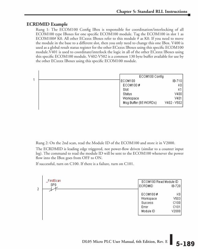
DL05 Micro PLC User Manual, 6th Edition, Rev. E 5-189
Chapter 5: Standard RLL Instructions
ECRDMID ExampleRung 1: The ECOM100 Config IBox is responsible for coordination/interlocking of all ECOM100 type IBoxes for one specific ECOM100 module. Tag the ECOM100 in slot 1 as ECOM100# K0. All other ECxxxx IBoxes refer to this module # as K0. If you need to move the module in the base to a different slot, then you only need to change this one IBox. V400 is used as a global result status register for the other ECxxxx IBoxes using this specific ECOM100 module.V401 is used to coordinate/interlock the logic in all of the other ECxxxx IBoxes using this specific ECOM100 module. V402-V502 is a common 130 byte buffer available for use by the other ECxxxx IBoxes using this specific ECOM100 module.
Rung 2: On the 2nd scan, read the Module ID of the ECOM100 and store it in V2000.
The ECRDMID is leading edge triggered, not power-flow driven (similar to a counter input leg). The command to read the module ID will be sent to the ECOM100 whenever the power flow into the IBox goes from OFF to ON.
If successful, turn on C100. If there is a failure, turn on C101.
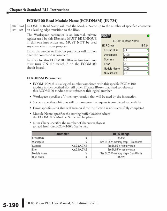
DL05 Micro PLC User Manual, 6th Edition, Rev. E5-190
Chapter 5: Standard RLL Instructions
ECOM100 Read Module Name (ECRDNAM) (IB-724)ECOM100 Read Name will read the Module Name up to the number of specified characters on a leading edge transition to the IBox.
The Workspace parameter is an internal, private register used by this IBox and MUST BE UNIQUE in this one instruction and MUST NOT be used anywhere else in your program.
Either the Success or Error bit parameter will turn on once the command is complete.
In order for this ECOM100 IBox to function, you must turn ON dip switch 7 on the ECOM100 circuit board.
ECRDNAM Parameters
• ECOM100#: this is a logical number associated with this specific ECOM100 module in the specified slot. All other ECxxxx IBoxes that need to reference this ECOM100 module must reference this logical number
• Workspace: specifies a V-memory location that will be used by the instruction
• Success: specifies a bit that will turn on once the request is completed successfully
• Error: specifies a bit that will turn on if the instruction is not successfully completed
• Module Name: specifies the starting buffer location where the ECOM100’s Module Name will be placed
• Num Chars: specifies the number of characters (bytes) to read from the ECOM100’s Name field
DS5 Used
HPP N/A
Parameter DL05 RangeECOM100# ⸠⸠⸠⸠⸠⸠⸠⸠⸠⸠⸠⸠⸠⸠⸠⸠⸠⸠⸠⸠⸠⸠⸠⸠⸠⸠⸠⸠⸠⸠⸠⸠⸠⸠⸠⸠⸠⸠⸠⸠⸠⸠⸠⸠⸠⸠⸠⸠⸠⸠⸠⸠⸠⸠⸠⸠⸠⸠⸠⸠⸠⸠ K K0-255Workspace ⸠⸠⸠⸠⸠⸠⸠⸠⸠⸠⸠⸠⸠⸠⸠⸠⸠⸠⸠⸠⸠⸠⸠⸠⸠⸠⸠⸠⸠⸠⸠⸠⸠⸠⸠⸠⸠⸠⸠⸠⸠⸠⸠⸠⸠⸠⸠⸠⸠⸠⸠⸠⸠⸠⸠⸠⸠⸠⸠⸠⸠⸠ V See DL05 V-memory map - Data WordsSuccess ⸠⸠⸠⸠⸠⸠⸠⸠⸠⸠⸠⸠⸠⸠⸠⸠⸠⸠⸠⸠⸠⸠⸠⸠⸠⸠⸠⸠⸠⸠⸠⸠⸠⸠⸠⸠⸠⸠⸠⸠⸠⸠⸠⸠⸠ X,Y,C,GX,GY,B See DL05 V-memory mapError ⸠⸠⸠⸠⸠⸠⸠⸠⸠⸠⸠⸠⸠⸠⸠⸠⸠⸠⸠⸠⸠⸠⸠⸠⸠⸠⸠⸠⸠⸠⸠⸠⸠⸠⸠⸠⸠⸠⸠⸠⸠⸠⸠⸠⸠⸠⸠⸠⸠⸠ X,Y,C,GX,GY,B See DL05 V-memory mapModule Name ⸠⸠⸠⸠⸠⸠⸠⸠⸠⸠⸠⸠⸠⸠⸠⸠⸠⸠⸠⸠⸠⸠⸠⸠⸠⸠⸠⸠⸠⸠⸠⸠⸠⸠⸠⸠⸠⸠⸠⸠⸠⸠⸠⸠⸠⸠⸠⸠⸠⸠⸠⸠⸠⸠⸠⸠⸠⸠ V See DL05 V-memory map - Data WordsNum Chars ⸠⸠⸠⸠⸠⸠⸠⸠⸠⸠⸠⸠⸠⸠⸠⸠⸠⸠⸠⸠⸠⸠⸠⸠⸠⸠⸠⸠⸠⸠⸠⸠⸠⸠⸠⸠⸠⸠⸠⸠⸠⸠⸠⸠⸠⸠⸠⸠⸠⸠⸠⸠⸠⸠⸠⸠⸠⸠⸠⸠⸠⸠⸠⸠ K K1-128
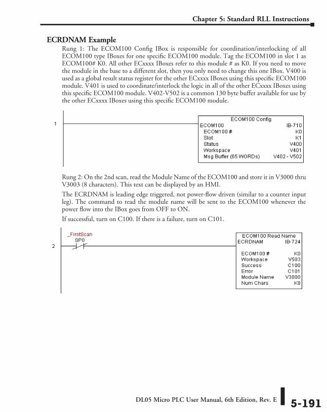
DL05 Micro PLC User Manual, 6th Edition, Rev. E 5-191
Chapter 5: Standard RLL Instructions
ECRDNAM ExampleRung 1: The ECOM100 Config IBox is responsible for coordination/interlocking of all ECOM100 type IBoxes for one specific ECOM100 module. Tag the ECOM100 in slot 1 as ECOM100# K0. All other ECxxxx IBoxes refer to this module # as K0. If you need to move the module in the base to a different slot, then you only need to change this one IBox. V400 is used as a global result status register for the other ECxxxx IBoxes using this specific ECOM100 module. V401 is used to coordinate/interlock the logic in all of the other ECxxxx IBoxes using this specific ECOM100 module. V402-V502 is a common 130 byte buffer available for use by the other ECxxxx IBoxes using this specific ECOM100 module.
Rung 2: On the 2nd scan, read the Module Name of the ECOM100 and store it in V3000 thru V3003 (8 characters). This text can be displayed by an HMI.
The ECRDNAM is leading edge triggered, not power-flow driven (similar to a counter input leg). The command to read the module name will be sent to the ECOM100 whenever the power flow into the IBox goes from OFF to ON.
If successful, turn on C100. If there is a failure, turn on C101.
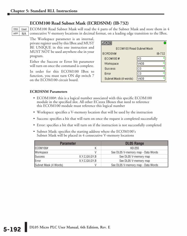
DL05 Micro PLC User Manual, 6th Edition, Rev. E5-192
Chapter 5: Standard RLL Instructions
ECOM100 Read Subnet Mask (ECRDSNM) (IB-732)ECOM100 Read Subnet Mask will read the 4 parts of the Subnet Mask and store them in 4 consecutive V-memory locations in decimal format, on a leading edge transition to the IBox.
The Workspace parameter is an internal, private register used by this IBox and MUST BE UNIQUE in this one instruction and MUST NOT be used anywhere else in your program.
Either the Success or Error bit parameter will turn on once the command is complete.
In order for this ECOM100 IBox to function, you must turn ON dip switch 7 on the ECOM100 circuit board.
ECRDSNM Parameters
• ECOM100#: this is a logical number associated with this specific ECOM100 module in the specified slot. All other ECxxxx IBoxes that need to reference this ECOM100 module must reference this logical number
• Workspace: specifies a V-memory location that will be used by the instruction
• Success: specifies a bit that will turn on once the request is completed successfully
• Error: specifies a bit that will turn on if the instruction is not successfully completed
• Subnet Mask: specifies the starting address where the ECOM100’s Subnet Mask will be placed in 4 consecutive V-memory locations
DS5 Used
HPP N/A
Parameter DL05 RangeECOM100# ⸠⸠⸠⸠⸠⸠⸠⸠⸠⸠⸠⸠⸠⸠⸠⸠⸠⸠⸠⸠⸠⸠⸠⸠⸠⸠⸠⸠⸠⸠⸠⸠⸠⸠⸠⸠⸠⸠⸠⸠⸠⸠⸠⸠⸠⸠⸠⸠⸠⸠⸠⸠⸠⸠⸠⸠⸠⸠⸠⸠⸠⸠ K K0-255Workspace ⸠⸠⸠⸠⸠⸠⸠⸠⸠⸠⸠⸠⸠⸠⸠⸠⸠⸠⸠⸠⸠⸠⸠⸠⸠⸠⸠⸠⸠⸠⸠⸠⸠⸠⸠⸠⸠⸠⸠⸠⸠⸠⸠⸠⸠⸠⸠⸠⸠⸠⸠⸠⸠⸠⸠⸠⸠⸠⸠⸠⸠⸠ V See DL05 V-memory map - Data WordsSuccess ⸠⸠⸠⸠⸠⸠⸠⸠⸠⸠⸠⸠⸠⸠⸠⸠⸠⸠⸠⸠⸠⸠⸠⸠⸠⸠⸠⸠⸠⸠⸠⸠⸠⸠⸠⸠⸠⸠⸠⸠⸠⸠⸠⸠⸠ X,Y,C,GX,GY,B See DL05 V-memory mapError ⸠⸠⸠⸠⸠⸠⸠⸠⸠⸠⸠⸠⸠⸠⸠⸠⸠⸠⸠⸠⸠⸠⸠⸠⸠⸠⸠⸠⸠⸠⸠⸠⸠⸠⸠⸠⸠⸠⸠⸠⸠⸠⸠⸠⸠⸠⸠⸠⸠⸠ X,Y,C,GX,GY,B See DL05 V-memory mapSubnet Mask (4 Words) ⸠⸠⸠⸠⸠⸠⸠⸠⸠⸠⸠⸠⸠⸠⸠⸠⸠⸠⸠⸠⸠⸠⸠⸠⸠⸠⸠⸠⸠⸠⸠⸠⸠⸠⸠⸠⸠⸠⸠⸠⸠⸠⸠ V See DL05 V-memory map - Data Words
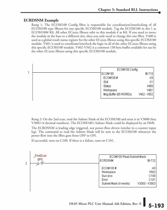
DL05 Micro PLC User Manual, 6th Edition, Rev. E 5-193
Chapter 5: Standard RLL Instructions
ECRDSNM ExampleRung 1: The ECOM100 Config IBox is responsible for coordination/interlocking of all ECOM100 type IBoxes for one specific ECOM100 module. Tag the ECOM100 in slot 1 as ECOM100# K0. All other ECxxxx IBoxes refer to this module # as K0. If you need to move the module in the base to a different slot, then you only need to change this one IBox. V400 is used as a global result status register for the other ECxxxx IBoxes using this specific ECOM100 module. V401 is used to coordinate/interlock the logic in all of the other ECxxxx IBoxes using this specific ECOM100 module. V402-V502 is a common 130 byte buffer available for use by the other ECxxxx IBoxes using this specific ECOM100 module.
Rung 2: On the 2nd scan, read the Subnet Mask of the ECOM100 and store it in V3000 thru V3003 (4 decimal numbers). The ECOM100’s Subnet Mask could be displayed by an HMI.
The ECRDSNM is leading edge triggered, not power-flow driven (similar to a counter input leg). The command to read the Subnet Mask will be sent to the ECOM100 whenever the power flow into the IBox goes from OFF to ON.
If successful, turn on C100. If there is a failure, turn on C101.
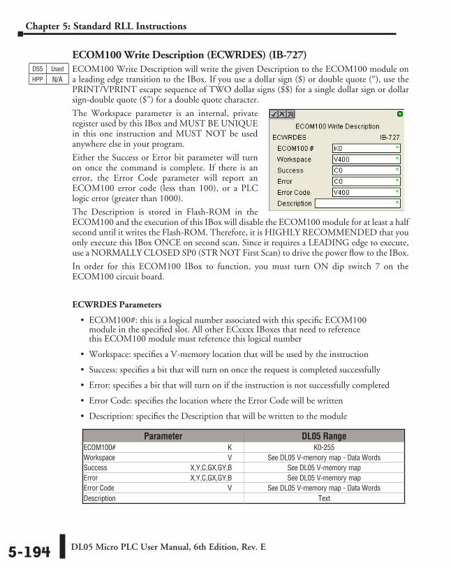
DL05 Micro PLC User Manual, 6th Edition, Rev. E5-194
Chapter 5: Standard RLL Instructions
ECOM100 Write Description (ECWRDES) (IB-727)ECOM100 Write Description will write the given Description to the ECOM100 module on a leading edge transition to the IBox. If you use a dollar sign ($) or double quote (“), use the PRINT/VPRINT escape sequence of TWO dollar signs ($$) for a single dollar sign or dollar sign-double quote ($”) for a double quote character.
The Workspace parameter is an internal, private register used by this IBox and MUST BE UNIQUE in this one instruction and MUST NOT be used anywhere else in your program.
Either the Success or Error bit parameter will turn on once the command is complete. If there is an error, the Error Code parameter will report an ECOM100 error code (less than 100), or a PLC logic error (greater than 1000).
The Description is stored in Flash-ROM in the ECOM100 and the execution of this IBox will disable the ECOM100 module for at least a half second until it writes the Flash-ROM. Therefore, it is HIGHLY RECOMMENDED that you only execute this IBox ONCE on second scan. Since it requires a LEADING edge to execute, use a NORMALLY CLOSED SP0 (STR NOT First Scan) to drive the power flow to the IBox.
In order for this ECOM100 IBox to function, you must turn ON dip switch 7 on the ECOM100 circuit board.
ECWRDES Parameters
• ECOM100#: this is a logical number associated with this specific ECOM100 module in the specified slot. All other ECxxxx IBoxes that need to reference this ECOM100 module must reference this logical number
• Workspace: specifies a V-memory location that will be used by the instruction
• Success: specifies a bit that will turn on once the request is completed successfully
• Error: specifies a bit that will turn on if the instruction is not successfully completed
• Error Code: specifies the location where the Error Code will be written
• Description: specifies the Description that will be written to the module
DS5 Used
HPP N/A
Parameter DL05 RangeECOM100# ⸠⸠⸠⸠⸠⸠⸠⸠⸠⸠⸠⸠⸠⸠⸠⸠⸠⸠⸠⸠⸠⸠⸠⸠⸠⸠⸠⸠⸠⸠⸠⸠⸠⸠⸠⸠⸠⸠⸠⸠⸠⸠⸠⸠⸠⸠⸠⸠⸠⸠⸠⸠⸠⸠⸠⸠⸠⸠⸠⸠⸠⸠ K K0-255Workspace ⸠⸠⸠⸠⸠⸠⸠⸠⸠⸠⸠⸠⸠⸠⸠⸠⸠⸠⸠⸠⸠⸠⸠⸠⸠⸠⸠⸠⸠⸠⸠⸠⸠⸠⸠⸠⸠⸠⸠⸠⸠⸠⸠⸠⸠⸠⸠⸠⸠⸠⸠⸠⸠⸠⸠⸠⸠⸠⸠⸠⸠⸠ V See DL05 V-memory map - Data WordsSuccess ⸠⸠⸠⸠⸠⸠⸠⸠⸠⸠⸠⸠⸠⸠⸠⸠⸠⸠⸠⸠⸠⸠⸠⸠⸠⸠⸠⸠⸠⸠⸠⸠⸠⸠⸠⸠⸠⸠⸠⸠⸠⸠⸠⸠⸠ X,Y,C,GX,GY,B See DL05 V-memory mapError ⸠⸠⸠⸠⸠⸠⸠⸠⸠⸠⸠⸠⸠⸠⸠⸠⸠⸠⸠⸠⸠⸠⸠⸠⸠⸠⸠⸠⸠⸠⸠⸠⸠⸠⸠⸠⸠⸠⸠⸠⸠⸠⸠⸠⸠⸠⸠⸠⸠⸠ X,Y,C,GX,GY,B See DL05 V-memory mapError Code ⸠⸠⸠⸠⸠⸠⸠⸠⸠⸠⸠⸠⸠⸠⸠⸠⸠⸠⸠⸠⸠⸠⸠⸠⸠⸠⸠⸠⸠⸠⸠⸠⸠⸠⸠⸠⸠⸠⸠⸠⸠⸠⸠⸠⸠⸠⸠⸠⸠⸠⸠⸠⸠⸠⸠⸠⸠⸠⸠⸠⸠⸠⸠ V See DL05 V-memory map - Data WordsDescription ⸠⸠⸠⸠⸠⸠⸠⸠⸠⸠⸠⸠⸠⸠⸠⸠⸠⸠⸠⸠⸠⸠⸠⸠⸠⸠⸠⸠⸠⸠⸠⸠⸠⸠⸠⸠⸠⸠⸠⸠⸠⸠⸠⸠⸠⸠⸠⸠⸠⸠⸠⸠⸠⸠⸠⸠⸠⸠⸠⸠⸠⸠⸠⸠⸠ Text
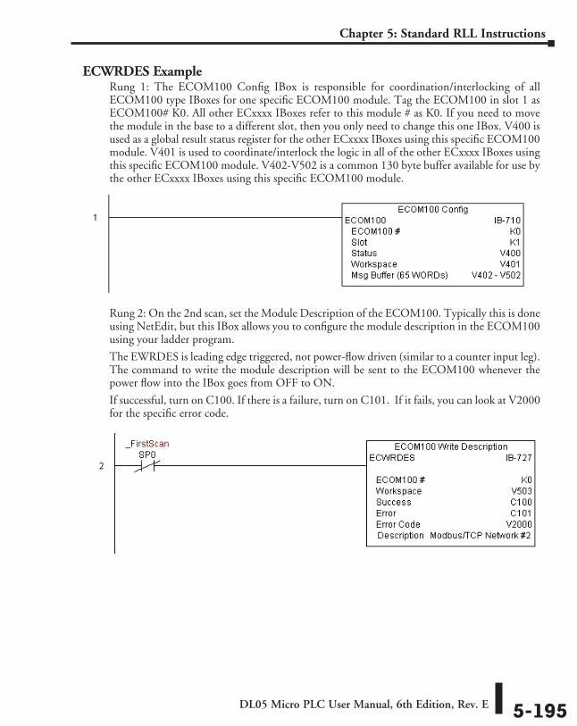
DL05 Micro PLC User Manual, 6th Edition, Rev. E 5-195
Chapter 5: Standard RLL Instructions
ECWRDES ExampleRung 1: The ECOM100 Config IBox is responsible for coordination/interlocking of all ECOM100 type IBoxes for one specific ECOM100 module. Tag the ECOM100 in slot 1 as ECOM100# K0. All other ECxxxx IBoxes refer to this module # as K0. If you need to move the module in the base to a different slot, then you only need to change this one IBox. V400 is used as a global result status register for the other ECxxxx IBoxes using this specific ECOM100 module. V401 is used to coordinate/interlock the logic in all of the other ECxxxx IBoxes using this specific ECOM100 module. V402-V502 is a common 130 byte buffer available for use by the other ECxxxx IBoxes using this specific ECOM100 module.
Rung 2: On the 2nd scan, set the Module Description of the ECOM100. Typically this is done using NetEdit, but this IBox allows you to configure the module description in the ECOM100 using your ladder program.
The EWRDES is leading edge triggered, not power-flow driven (similar to a counter input leg). The command to write the module description will be sent to the ECOM100 whenever the power flow into the IBox goes from OFF to ON.
If successful, turn on C100. If there is a failure, turn on C101. If it fails, you can look at V2000 for the specific error code.
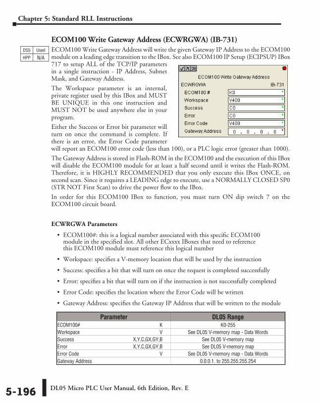
DL05 Micro PLC User Manual, 6th Edition, Rev. E5-196
Chapter 5: Standard RLL Instructions
ECOM100 Write Gateway Address (ECWRGWA) (IB-731)ECOM100 Write Gateway Address will write the given Gateway IP Address to the ECOM100 module on a leading edge transition to the IBox. See also ECOM100 IP Setup (ECIPSUP) IBox 717 to setup ALL of the TCP/IP parameters in a single instruction - IP Address, Subnet Mask, and Gateway Address.
The Workspace parameter is an internal, private register used by this IBox and MUST BE UNIQUE in this one instruction and MUST NOT be used anywhere else in your program.
Either the Success or Error bit parameter will turn on once the command is complete. If there is an error, the Error Code parameter will report an ECOM100 error code (less than 100), or a PLC logic error (greater than 1000).
The Gateway Address is stored in Flash-ROM in the ECOM100 and the execution of this IBox will disable the ECOM100 module for at least a half second until it writes the Flash-ROM. Therefore, it is HIGHLY RECOMMENDED that you only execute this IBox ONCE, on second scan. Since it requires a LEADING edge to execute, use a NORMALLY CLOSED SP0 (STR NOT First Scan) to drive the power flow to the IBox.
In order for this ECOM100 IBox to function, you must turn ON dip switch 7 on the ECOM100 circuit board.
ECWRGWA Parameters
• ECOM100#: this is a logical number associated with this specific ECOM100 module in the specified slot. All other ECxxxx IBoxes that need to reference this ECOM100 module must reference this logical number
• Workspace: specifies a V-memory location that will be used by the instruction
• Success: specifies a bit that will turn on once the request is completed successfully
• Error: specifies a bit that will turn on if the instruction is not successfully completed
• Error Code: specifies the location where the Error Code will be written
• Gateway Address: specifies the Gateway IP Address that will be written to the module
DS5 Used
HPP N/A
Parameter DL05 RangeECOM100# ⸠⸠⸠⸠⸠⸠⸠⸠⸠⸠⸠⸠⸠⸠⸠⸠⸠⸠⸠⸠⸠⸠⸠⸠⸠⸠⸠⸠⸠⸠⸠⸠⸠⸠⸠⸠⸠⸠⸠⸠⸠⸠⸠⸠⸠⸠⸠⸠⸠⸠⸠⸠⸠⸠⸠⸠⸠⸠⸠⸠⸠⸠ K K0-255Workspace ⸠⸠⸠⸠⸠⸠⸠⸠⸠⸠⸠⸠⸠⸠⸠⸠⸠⸠⸠⸠⸠⸠⸠⸠⸠⸠⸠⸠⸠⸠⸠⸠⸠⸠⸠⸠⸠⸠⸠⸠⸠⸠⸠⸠⸠⸠⸠⸠⸠⸠⸠⸠⸠⸠⸠⸠⸠⸠⸠⸠⸠⸠ V See DL05 V-memory map - Data WordsSuccess ⸠⸠⸠⸠⸠⸠⸠⸠⸠⸠⸠⸠⸠⸠⸠⸠⸠⸠⸠⸠⸠⸠⸠⸠⸠⸠⸠⸠⸠⸠⸠⸠⸠⸠⸠⸠⸠⸠⸠⸠⸠⸠⸠⸠⸠ X,Y,C,GX,GY,B See DL05 V-memory mapError ⸠⸠⸠⸠⸠⸠⸠⸠⸠⸠⸠⸠⸠⸠⸠⸠⸠⸠⸠⸠⸠⸠⸠⸠⸠⸠⸠⸠⸠⸠⸠⸠⸠⸠⸠⸠⸠⸠⸠⸠⸠⸠⸠⸠⸠⸠⸠⸠⸠⸠ X,Y,C,GX,GY,B See DL05 V-memory mapError Code ⸠⸠⸠⸠⸠⸠⸠⸠⸠⸠⸠⸠⸠⸠⸠⸠⸠⸠⸠⸠⸠⸠⸠⸠⸠⸠⸠⸠⸠⸠⸠⸠⸠⸠⸠⸠⸠⸠⸠⸠⸠⸠⸠⸠⸠⸠⸠⸠⸠⸠⸠⸠⸠⸠⸠⸠⸠⸠⸠⸠⸠⸠⸠ V See DL05 V-memory map - Data WordsGateway Address ⸠⸠⸠⸠⸠⸠⸠⸠⸠⸠⸠⸠⸠⸠⸠⸠⸠⸠⸠⸠⸠⸠⸠⸠⸠⸠⸠⸠⸠⸠⸠⸠⸠⸠⸠⸠⸠⸠⸠⸠⸠⸠⸠⸠⸠⸠⸠⸠⸠⸠⸠⸠⸠⸠⸠ 0.0.0.1. to 255.255.255.254
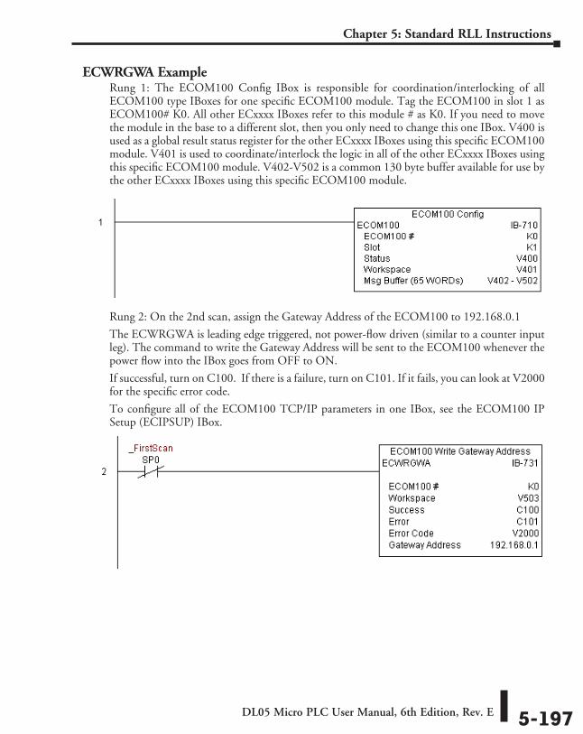
DL05 Micro PLC User Manual, 6th Edition, Rev. E 5-197
Chapter 5: Standard RLL Instructions
ECWRGWA ExampleRung 1: The ECOM100 Config IBox is responsible for coordination/interlocking of all ECOM100 type IBoxes for one specific ECOM100 module. Tag the ECOM100 in slot 1 as ECOM100# K0. All other ECxxxx IBoxes refer to this module # as K0. If you need to move the module in the base to a different slot, then you only need to change this one IBox. V400 is used as a global result status register for the other ECxxxx IBoxes using this specific ECOM100 module. V401 is used to coordinate/interlock the logic in all of the other ECxxxx IBoxes using this specific ECOM100 module. V402-V502 is a common 130 byte buffer available for use by the other ECxxxx IBoxes using this specific ECOM100 module.
Rung 2: On the 2nd scan, assign the Gateway Address of the ECOM100 to 192.168.0.1
The ECWRGWA is leading edge triggered, not power-flow driven (similar to a counter input leg). The command to write the Gateway Address will be sent to the ECOM100 whenever the power flow into the IBox goes from OFF to ON.
If successful, turn on C100. If there is a failure, turn on C101. If it fails, you can look at V2000 for the specific error code.
To configure all of the ECOM100 TCP/IP parameters in one IBox, see the ECOM100 IP Setup (ECIPSUP) IBox.
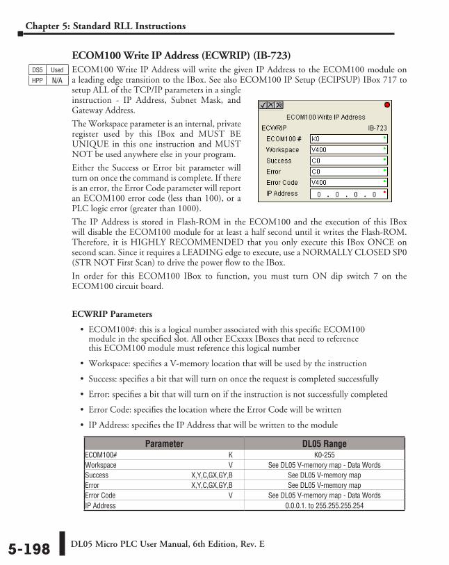
DL05 Micro PLC User Manual, 6th Edition, Rev. E5-198
Chapter 5: Standard RLL Instructions
ECOM100 Write IP Address (ECWRIP) (IB-723)ECOM100 Write IP Address will write the given IP Address to the ECOM100 module on a leading edge transition to the IBox. See also ECOM100 IP Setup (ECIPSUP) IBox 717 to setup ALL of the TCP/IP parameters in a single instruction - IP Address, Subnet Mask, and Gateway Address.
The Workspace parameter is an internal, private register used by this IBox and MUST BE UNIQUE in this one instruction and MUST NOT be used anywhere else in your program.
Either the Success or Error bit parameter will turn on once the command is complete. If there is an error, the Error Code parameter will report an ECOM100 error code (less than 100), or a PLC logic error (greater than 1000).
The IP Address is stored in Flash-ROM in the ECOM100 and the execution of this IBox will disable the ECOM100 module for at least a half second until it writes the Flash-ROM. Therefore, it is HIGHLY RECOMMENDED that you only execute this IBox ONCE on second scan. Since it requires a LEADING edge to execute, use a NORMALLY CLOSED SP0 (STR NOT First Scan) to drive the power flow to the IBox.
In order for this ECOM100 IBox to function, you must turn ON dip switch 7 on the ECOM100 circuit board.
ECWRIP Parameters
• ECOM100#: this is a logical number associated with this specific ECOM100 module in the specified slot. All other ECxxxx IBoxes that need to reference this ECOM100 module must reference this logical number
• Workspace: specifies a V-memory location that will be used by the instruction
• Success: specifies a bit that will turn on once the request is completed successfully
• Error: specifies a bit that will turn on if the instruction is not successfully completed
• Error Code: specifies the location where the Error Code will be written
• IP Address: specifies the IP Address that will be written to the module
DS5 Used
HPP N/A
Parameter DL05 RangeECOM100# ⸠⸠⸠⸠⸠⸠⸠⸠⸠⸠⸠⸠⸠⸠⸠⸠⸠⸠⸠⸠⸠⸠⸠⸠⸠⸠⸠⸠⸠⸠⸠⸠⸠⸠⸠⸠⸠⸠⸠⸠⸠⸠⸠⸠⸠⸠⸠⸠⸠⸠⸠⸠⸠⸠⸠⸠⸠⸠⸠⸠⸠⸠ K K0-255Workspace ⸠⸠⸠⸠⸠⸠⸠⸠⸠⸠⸠⸠⸠⸠⸠⸠⸠⸠⸠⸠⸠⸠⸠⸠⸠⸠⸠⸠⸠⸠⸠⸠⸠⸠⸠⸠⸠⸠⸠⸠⸠⸠⸠⸠⸠⸠⸠⸠⸠⸠⸠⸠⸠⸠⸠⸠⸠⸠⸠⸠⸠⸠ V See DL05 V-memory map - Data WordsSuccess ⸠⸠⸠⸠⸠⸠⸠⸠⸠⸠⸠⸠⸠⸠⸠⸠⸠⸠⸠⸠⸠⸠⸠⸠⸠⸠⸠⸠⸠⸠⸠⸠⸠⸠⸠⸠⸠⸠⸠⸠⸠⸠⸠⸠⸠ X,Y,C,GX,GY,B See DL05 V-memory mapError ⸠⸠⸠⸠⸠⸠⸠⸠⸠⸠⸠⸠⸠⸠⸠⸠⸠⸠⸠⸠⸠⸠⸠⸠⸠⸠⸠⸠⸠⸠⸠⸠⸠⸠⸠⸠⸠⸠⸠⸠⸠⸠⸠⸠⸠⸠⸠⸠⸠⸠ X,Y,C,GX,GY,B See DL05 V-memory mapError Code ⸠⸠⸠⸠⸠⸠⸠⸠⸠⸠⸠⸠⸠⸠⸠⸠⸠⸠⸠⸠⸠⸠⸠⸠⸠⸠⸠⸠⸠⸠⸠⸠⸠⸠⸠⸠⸠⸠⸠⸠⸠⸠⸠⸠⸠⸠⸠⸠⸠⸠⸠⸠⸠⸠⸠⸠⸠⸠⸠⸠⸠⸠⸠ V See DL05 V-memory map - Data WordsIP Address ⸠⸠⸠⸠⸠⸠⸠⸠⸠⸠⸠⸠⸠⸠⸠⸠⸠⸠⸠⸠⸠⸠⸠⸠⸠⸠⸠⸠⸠⸠⸠⸠⸠⸠⸠⸠⸠⸠⸠⸠⸠⸠⸠⸠⸠⸠⸠⸠⸠⸠⸠⸠⸠⸠⸠⸠⸠⸠⸠⸠⸠⸠⸠⸠⸠ 0.0.0.1. to 255.255.255.254
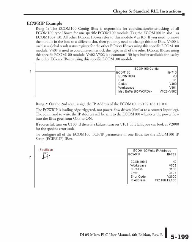
DL05 Micro PLC User Manual, 6th Edition, Rev. E 5-199
Chapter 5: Standard RLL Instructions
ECWRIP ExampleRung 1: The ECOM100 Config IBox is responsible for coordination/interlocking of all ECOM100 type IBoxes for one specific ECOM100 module. Tag the ECOM100 in slot 1 as ECOM100# K0. All other ECxxxx IBoxes refer to this module # as K0. If you need to move the module in the base to a different slot, then you only need to change this one IBox. V400 is used as a global result status register for the other ECxxxx IBoxes using this specific ECOM100 module. V401 is used to coordinate/interlock the logic in all of the other ECxxxx IBoxes using this specific ECOM100 module. V402-V502 is a common 130 byte buffer available for use by the other ECxxxx IBoxes using this specific ECOM100 module.
Rung 2: On the 2nd scan, assign the IP Address of the ECOM100 to 192.168.12.100
The ECWRIP is leading edge triggered, not power-flow driven (similar to a counter input leg). The command to write the IP Address will be sent to the ECOM100 whenever the power flow into the IBox goes from OFF to ON.
If successful, turn on C100. If there is a failure, turn on C101. If it fails, you can look at V2000 for the specific error code.
To configure all of the ECOM100 TCP/IP parameters in one IBox, see the ECOM100 IP Setup (ECIPSUP) IBox.
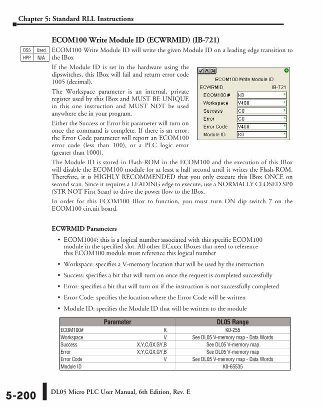
DL05 Micro PLC User Manual, 6th Edition, Rev. E5-200
Chapter 5: Standard RLL Instructions
ECOM100 Write Module ID (ECWRMID) (IB-721)ECOM100 Write Module ID will write the given Module ID on a leading edge transition to the IBox
If the Module ID is set in the hardware using the dipswitches, this IBox will fail and return error code 1005 (decimal).
The Workspace parameter is an internal, private register used by this IBox and MUST BE UNIQUE in this one instruction and MUST NOT be used anywhere else in your program.
Either the Success or Error bit parameter will turn on once the command is complete. If there is an error, the Error Code parameter will report an ECOM100 error code (less than 100), or a PLC logic error (greater than 1000).
The Module ID is stored in Flash-ROM in the ECOM100 and the execution of this IBox will disable the ECOM100 module for at least a half second until it writes the Flash-ROM. Therefore, it is HIGHLY RECOMMENDED that you only execute this IBox ONCE on second scan. Since it requires a LEADING edge to execute, use a NORMALLY CLOSED SP0 (STR NOT First Scan) to drive the power flow to the IBox.
In order for this ECOM100 IBox to function, you must turn ON dip switch 7 on the ECOM100 circuit board.
ECWRMID Parameters
• ECOM100#: this is a logical number associated with this specific ECOM100 module in the specified slot. All other ECxxxx IBoxes that need to reference this ECOM100 module must reference this logical number
• Workspace: specifies a V-memory location that will be used by the instruction
• Success: specifies a bit that will turn on once the request is completed successfully
• Error: specifies a bit that will turn on if the instruction is not successfully completed
• Error Code: specifies the location where the Error Code will be written
• Module ID: specifies the Module ID that will be written to the module
DS5 Used
HPP N/A
Parameter DL05 RangeECOM100# ⸠⸠⸠⸠⸠⸠⸠⸠⸠⸠⸠⸠⸠⸠⸠⸠⸠⸠⸠⸠⸠⸠⸠⸠⸠⸠⸠⸠⸠⸠⸠⸠⸠⸠⸠⸠⸠⸠⸠⸠⸠⸠⸠⸠⸠⸠⸠⸠⸠⸠⸠⸠⸠⸠⸠⸠⸠⸠⸠⸠⸠⸠ K K0-255Workspace ⸠⸠⸠⸠⸠⸠⸠⸠⸠⸠⸠⸠⸠⸠⸠⸠⸠⸠⸠⸠⸠⸠⸠⸠⸠⸠⸠⸠⸠⸠⸠⸠⸠⸠⸠⸠⸠⸠⸠⸠⸠⸠⸠⸠⸠⸠⸠⸠⸠⸠⸠⸠⸠⸠⸠⸠⸠⸠⸠⸠⸠⸠ V See DL05 V-memory map - Data WordsSuccess ⸠⸠⸠⸠⸠⸠⸠⸠⸠⸠⸠⸠⸠⸠⸠⸠⸠⸠⸠⸠⸠⸠⸠⸠⸠⸠⸠⸠⸠⸠⸠⸠⸠⸠⸠⸠⸠⸠⸠⸠⸠⸠⸠⸠⸠ X,Y,C,GX,GY,B See DL05 V-memory mapError ⸠⸠⸠⸠⸠⸠⸠⸠⸠⸠⸠⸠⸠⸠⸠⸠⸠⸠⸠⸠⸠⸠⸠⸠⸠⸠⸠⸠⸠⸠⸠⸠⸠⸠⸠⸠⸠⸠⸠⸠⸠⸠⸠⸠⸠⸠⸠⸠⸠⸠ X,Y,C,GX,GY,B See DL05 V-memory mapError Code ⸠⸠⸠⸠⸠⸠⸠⸠⸠⸠⸠⸠⸠⸠⸠⸠⸠⸠⸠⸠⸠⸠⸠⸠⸠⸠⸠⸠⸠⸠⸠⸠⸠⸠⸠⸠⸠⸠⸠⸠⸠⸠⸠⸠⸠⸠⸠⸠⸠⸠⸠⸠⸠⸠⸠⸠⸠⸠⸠⸠⸠⸠⸠ V See DL05 V-memory map - Data WordsModule ID ⸠⸠⸠⸠⸠⸠⸠⸠⸠⸠⸠⸠⸠⸠⸠⸠⸠⸠⸠⸠⸠⸠⸠⸠⸠⸠⸠⸠⸠⸠⸠⸠⸠⸠⸠⸠⸠⸠⸠⸠⸠⸠⸠⸠⸠⸠⸠⸠⸠⸠⸠⸠⸠⸠⸠⸠⸠⸠⸠⸠⸠⸠⸠⸠⸠⸠ K0-65535
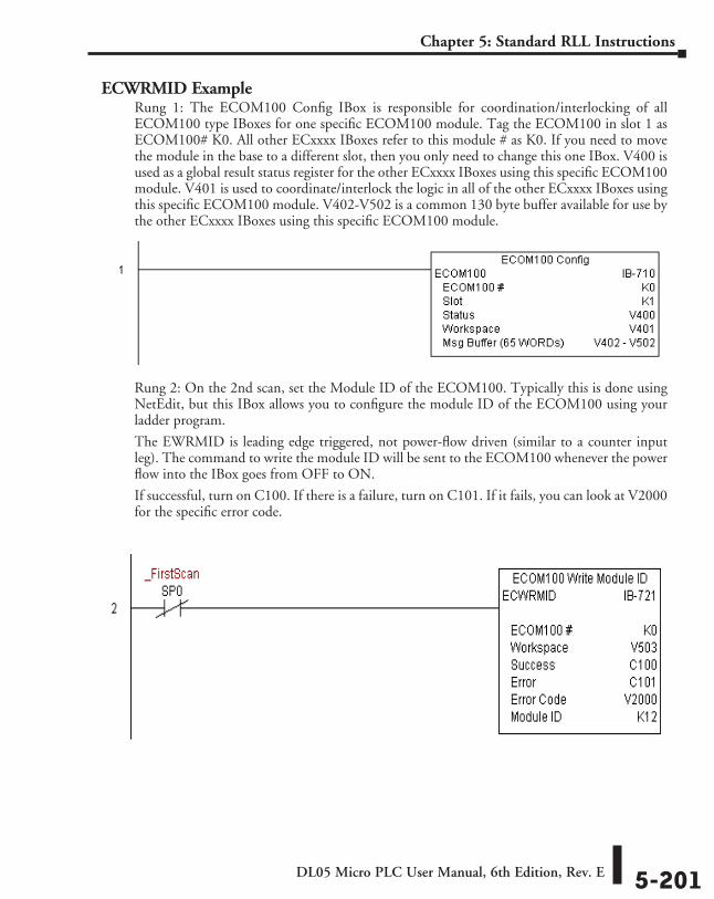
DL05 Micro PLC User Manual, 6th Edition, Rev. E 5-201
Chapter 5: Standard RLL Instructions
ECWRMID ExampleRung 1: The ECOM100 Config IBox is responsible for coordination/interlocking of all ECOM100 type IBoxes for one specific ECOM100 module. Tag the ECOM100 in slot 1 as ECOM100# K0. All other ECxxxx IBoxes refer to this module # as K0. If you need to move the module in the base to a different slot, then you only need to change this one IBox. V400 is used as a global result status register for the other ECxxxx IBoxes using this specific ECOM100 module. V401 is used to coordinate/interlock the logic in all of the other ECxxxx IBoxes using this specific ECOM100 module. V402-V502 is a common 130 byte buffer available for use by the other ECxxxx IBoxes using this specific ECOM100 module.
Rung 2: On the 2nd scan, set the Module ID of the ECOM100. Typically this is done using NetEdit, but this IBox allows you to configure the module ID of the ECOM100 using your ladder program.
The EWRMID is leading edge triggered, not power-flow driven (similar to a counter input leg). The command to write the module ID will be sent to the ECOM100 whenever the power flow into the IBox goes from OFF to ON.
If successful, turn on C100. If there is a failure, turn on C101. If it fails, you can look at V2000 for the specific error code.
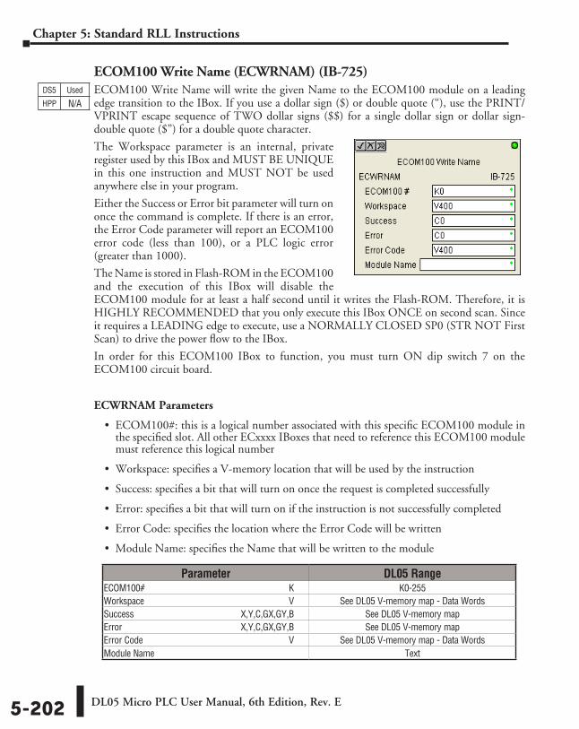
DL05 Micro PLC User Manual, 6th Edition, Rev. E5-202
Chapter 5: Standard RLL Instructions
ECOM100 Write Name (ECWRNAM) (IB-725)ECOM100 Write Name will write the given Name to the ECOM100 module on a leading edge transition to the IBox. If you use a dollar sign ($) or double quote (“), use the PRINT/VPRINT escape sequence of TWO dollar signs ($$) for a single dollar sign or dollar sign-double quote ($”) for a double quote character.
The Workspace parameter is an internal, private register used by this IBox and MUST BE UNIQUE in this one instruction and MUST NOT be used anywhere else in your program.
Either the Success or Error bit parameter will turn on once the command is complete. If there is an error, the Error Code parameter will report an ECOM100 error code (less than 100), or a PLC logic error (greater than 1000).
The Name is stored in Flash-ROM in the ECOM100 and the execution of this IBox will disable the ECOM100 module for at least a half second until it writes the Flash-ROM. Therefore, it is HIGHLY RECOMMENDED that you only execute this IBox ONCE on second scan. Since it requires a LEADING edge to execute, use a NORMALLY CLOSED SP0 (STR NOT First Scan) to drive the power flow to the IBox.
In order for this ECOM100 IBox to function, you must turn ON dip switch 7 on the ECOM100 circuit board.
ECWRNAM Parameters
• ECOM100#: this is a logical number associated with this specific ECOM100 module in the specified slot. All other ECxxxx IBoxes that need to reference this ECOM100 module must reference this logical number
• Workspace: specifies a V-memory location that will be used by the instruction
• Success: specifies a bit that will turn on once the request is completed successfully
• Error: specifies a bit that will turn on if the instruction is not successfully completed
• Error Code: specifies the location where the Error Code will be written
• Module Name: specifies the Name that will be written to the module
DS5 Used
HPP N/A
Parameter DL05 RangeECOM100# ⸠⸠⸠⸠⸠⸠⸠⸠⸠⸠⸠⸠⸠⸠⸠⸠⸠⸠⸠⸠⸠⸠⸠⸠⸠⸠⸠⸠⸠⸠⸠⸠⸠⸠⸠⸠⸠⸠⸠⸠⸠⸠⸠⸠⸠⸠⸠⸠⸠⸠⸠⸠⸠⸠⸠⸠⸠⸠⸠⸠⸠⸠ K K0-255Workspace ⸠⸠⸠⸠⸠⸠⸠⸠⸠⸠⸠⸠⸠⸠⸠⸠⸠⸠⸠⸠⸠⸠⸠⸠⸠⸠⸠⸠⸠⸠⸠⸠⸠⸠⸠⸠⸠⸠⸠⸠⸠⸠⸠⸠⸠⸠⸠⸠⸠⸠⸠⸠⸠⸠⸠⸠⸠⸠⸠⸠⸠⸠ V See DL05 V-memory map - Data WordsSuccess ⸠⸠⸠⸠⸠⸠⸠⸠⸠⸠⸠⸠⸠⸠⸠⸠⸠⸠⸠⸠⸠⸠⸠⸠⸠⸠⸠⸠⸠⸠⸠⸠⸠⸠⸠⸠⸠⸠⸠⸠⸠⸠⸠⸠⸠ X,Y,C,GX,GY,B See DL05 V-memory mapError ⸠⸠⸠⸠⸠⸠⸠⸠⸠⸠⸠⸠⸠⸠⸠⸠⸠⸠⸠⸠⸠⸠⸠⸠⸠⸠⸠⸠⸠⸠⸠⸠⸠⸠⸠⸠⸠⸠⸠⸠⸠⸠⸠⸠⸠⸠⸠⸠⸠⸠ X,Y,C,GX,GY,B See DL05 V-memory mapError Code ⸠⸠⸠⸠⸠⸠⸠⸠⸠⸠⸠⸠⸠⸠⸠⸠⸠⸠⸠⸠⸠⸠⸠⸠⸠⸠⸠⸠⸠⸠⸠⸠⸠⸠⸠⸠⸠⸠⸠⸠⸠⸠⸠⸠⸠⸠⸠⸠⸠⸠⸠⸠⸠⸠⸠⸠⸠⸠⸠⸠⸠⸠⸠ V See DL05 V-memory map - Data WordsModule Name ⸠⸠⸠⸠⸠⸠⸠⸠⸠⸠⸠⸠⸠⸠⸠⸠⸠⸠⸠⸠⸠⸠⸠⸠⸠⸠⸠⸠⸠⸠⸠⸠⸠⸠⸠⸠⸠⸠⸠⸠⸠⸠⸠⸠⸠⸠⸠⸠⸠⸠⸠⸠⸠⸠⸠⸠⸠⸠⸠⸠⸠ Text
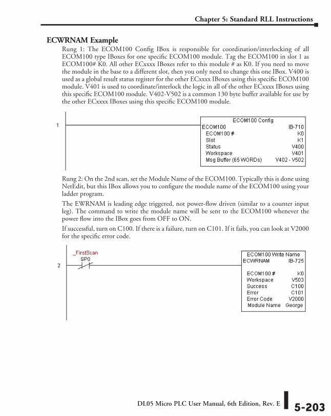
DL05 Micro PLC User Manual, 6th Edition, Rev. E 5-203
Chapter 5: Standard RLL Instructions
ECWRNAM ExampleRung 1: The ECOM100 Config IBox is responsible for coordination/interlocking of all ECOM100 type IBoxes for one specific ECOM100 module. Tag the ECOM100 in slot 1 as ECOM100# K0. All other ECxxxx IBoxes refer to this module # as K0. If you need to move the module in the base to a different slot, then you only need to change this one IBox. V400 is used as a global result status register for the other ECxxxx IBoxes using this specific ECOM100 module. V401 is used to coordinate/interlock the logic in all of the other ECxxxx IBoxes using this specific ECOM100 module. V402-V502 is a common 130 byte buffer available for use by the other ECxxxx IBoxes using this specific ECOM100 module.
Rung 2: On the 2nd scan, set the Module Name of the ECOM100. Typically this is done using NetEdit, but this IBox allows you to configure the module name of the ECOM100 using your ladder program.
The EWRNAM is leading edge triggered, not power-flow driven (similar to a counter input leg). The command to write the module name will be sent to the ECOM100 whenever the power flow into the IBox goes from OFF to ON.
If successful, turn on C100. If there is a failure, turn on C101. If it fails, you can look at V2000 for the specific error code.
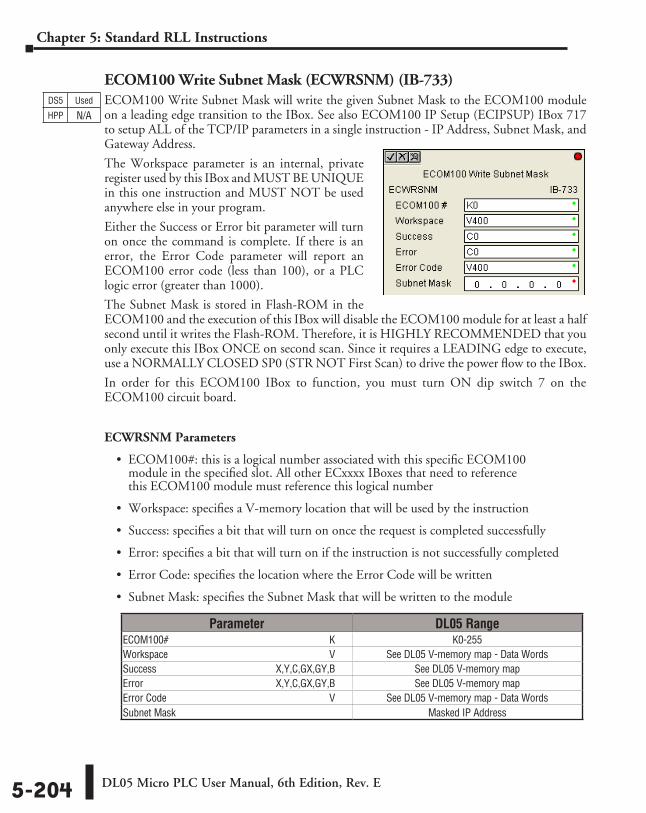
DL05 Micro PLC User Manual, 6th Edition, Rev. E5-204
Chapter 5: Standard RLL Instructions
ECOM100 Write Subnet Mask (ECWRSNM) (IB-733)ECOM100 Write Subnet Mask will write the given Subnet Mask to the ECOM100 module on a leading edge transition to the IBox. See also ECOM100 IP Setup (ECIPSUP) IBox 717 to setup ALL of the TCP/IP parameters in a single instruction - IP Address, Subnet Mask, and Gateway Address.
The Workspace parameter is an internal, private register used by this IBox and MUST BE UNIQUE in this one instruction and MUST NOT be used anywhere else in your program.
Either the Success or Error bit parameter will turn on once the command is complete. If there is an error, the Error Code parameter will report an ECOM100 error code (less than 100), or a PLC logic error (greater than 1000).
The Subnet Mask is stored in Flash-ROM in the ECOM100 and the execution of this IBox will disable the ECOM100 module for at least a half second until it writes the Flash-ROM. Therefore, it is HIGHLY RECOMMENDED that you only execute this IBox ONCE on second scan. Since it requires a LEADING edge to execute, use a NORMALLY CLOSED SP0 (STR NOT First Scan) to drive the power flow to the IBox.
In order for this ECOM100 IBox to function, you must turn ON dip switch 7 on the ECOM100 circuit board.
ECWRSNM Parameters
• ECOM100#: this is a logical number associated with this specific ECOM100 module in the specified slot. All other ECxxxx IBoxes that need to reference this ECOM100 module must reference this logical number
• Workspace: specifies a V-memory location that will be used by the instruction
• Success: specifies a bit that will turn on once the request is completed successfully
• Error: specifies a bit that will turn on if the instruction is not successfully completed
• Error Code: specifies the location where the Error Code will be written
• Subnet Mask: specifies the Subnet Mask that will be written to the module
DS5 Used
HPP N/A
Parameter DL05 RangeECOM100# ⸠⸠⸠⸠⸠⸠⸠⸠⸠⸠⸠⸠⸠⸠⸠⸠⸠⸠⸠⸠⸠⸠⸠⸠⸠⸠⸠⸠⸠⸠⸠⸠⸠⸠⸠⸠⸠⸠⸠⸠⸠⸠⸠⸠⸠⸠⸠⸠⸠⸠⸠⸠⸠⸠⸠⸠⸠⸠⸠⸠⸠⸠ K K0-255Workspace ⸠⸠⸠⸠⸠⸠⸠⸠⸠⸠⸠⸠⸠⸠⸠⸠⸠⸠⸠⸠⸠⸠⸠⸠⸠⸠⸠⸠⸠⸠⸠⸠⸠⸠⸠⸠⸠⸠⸠⸠⸠⸠⸠⸠⸠⸠⸠⸠⸠⸠⸠⸠⸠⸠⸠⸠⸠⸠⸠⸠⸠⸠ V See DL05 V-memory map - Data WordsSuccess ⸠⸠⸠⸠⸠⸠⸠⸠⸠⸠⸠⸠⸠⸠⸠⸠⸠⸠⸠⸠⸠⸠⸠⸠⸠⸠⸠⸠⸠⸠⸠⸠⸠⸠⸠⸠⸠⸠⸠⸠⸠⸠⸠⸠⸠ X,Y,C,GX,GY,B See DL05 V-memory mapError ⸠⸠⸠⸠⸠⸠⸠⸠⸠⸠⸠⸠⸠⸠⸠⸠⸠⸠⸠⸠⸠⸠⸠⸠⸠⸠⸠⸠⸠⸠⸠⸠⸠⸠⸠⸠⸠⸠⸠⸠⸠⸠⸠⸠⸠⸠⸠⸠⸠⸠ X,Y,C,GX,GY,B See DL05 V-memory mapError Code ⸠⸠⸠⸠⸠⸠⸠⸠⸠⸠⸠⸠⸠⸠⸠⸠⸠⸠⸠⸠⸠⸠⸠⸠⸠⸠⸠⸠⸠⸠⸠⸠⸠⸠⸠⸠⸠⸠⸠⸠⸠⸠⸠⸠⸠⸠⸠⸠⸠⸠⸠⸠⸠⸠⸠⸠⸠⸠⸠⸠⸠⸠⸠ V See DL05 V-memory map - Data WordsSubnet Mask ⸠⸠⸠⸠⸠⸠⸠⸠⸠⸠⸠⸠⸠⸠⸠⸠⸠⸠⸠⸠⸠⸠⸠⸠⸠⸠⸠⸠⸠⸠⸠⸠⸠⸠⸠⸠⸠⸠⸠⸠⸠⸠⸠⸠⸠⸠⸠⸠⸠⸠⸠⸠⸠⸠⸠⸠⸠⸠⸠⸠⸠⸠ Masked IP Address
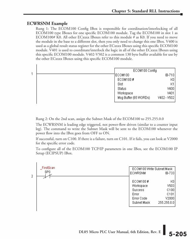
DL05 Micro PLC User Manual, 6th Edition, Rev. E 5-205
Chapter 5: Standard RLL Instructions
ECWRSNM ExampleRung 1: The ECOM100 Config IBox is responsible for coordination/interlocking of all ECOM100 type IBoxes for one specific ECOM100 module. Tag the ECOM100 in slot 1 as ECOM100# K0. All other ECxxxx IBoxes refer to this module # as K0. If you need to move the module in the base to a different slot, then you only need to change this one IBox. V400 is used as a global result status register for the other ECxxxx IBoxes using this specific ECOM100 module. V401 is used to coordinate/interlock the logic in all of the other ECxxxx IBoxes using this specific ECOM100 module. V402-V502 is a common 130 byte buffer available for use by the other ECxxxx IBoxes using this specific ECOM100 module.
Rung 2: On the 2nd scan, assign the Subnet Mask of the ECOM100 to 255.255.0.0
The ECWRSNM is leading edge triggered, not power-flow driven (similar to a counter input leg). The command to write the Subnet Mask will be sent to the ECOM100 whenever the power flow into the IBox goes from OFF to ON.
If successful, turn on C100. If there is a failure, turn on C101. If it fails, you can look at V2000 for the specific error code.
To configure all of the ECOM100 TCP/IP parameters in one IBox, see the ECOM100 IP Setup (ECIPSUP) IBox.
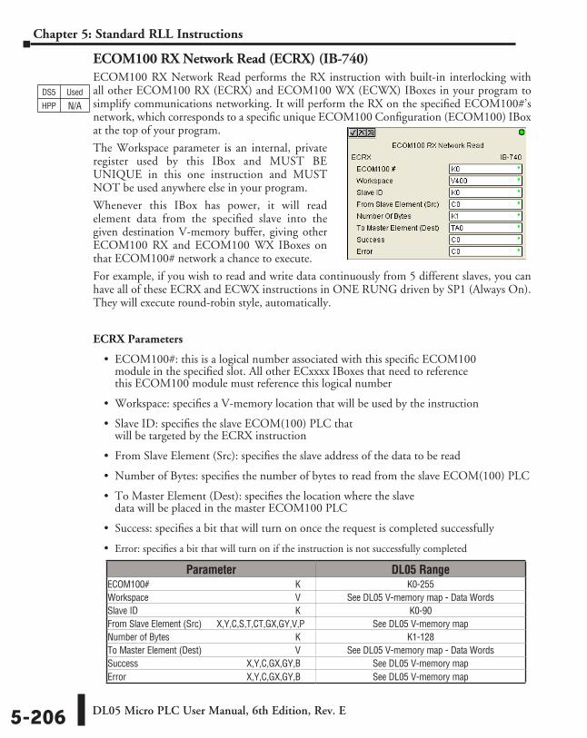
DL05 Micro PLC User Manual, 6th Edition, Rev. E5-206
Chapter 5: Standard RLL Instructions
ECOM100 RX Network Read (ECRX) (IB-740)ECOM100 RX Network Read performs the RX instruction with built-in interlocking with all other ECOM100 RX (ECRX) and ECOM100 WX (ECWX) IBoxes in your program to simplify communications networking. It will perform the RX on the specified ECOM100#’s network, which corresponds to a specific unique ECOM100 Configuration (ECOM100) IBox at the top of your program.
The Workspace parameter is an internal, private register used by this IBox and MUST BE UNIQUE in this one instruction and MUST NOT be used anywhere else in your program.
Whenever this IBox has power, it will read element data from the specified slave into the given destination V-memory buffer, giving other ECOM100 RX and ECOM100 WX IBoxes on that ECOM100# network a chance to execute.
For example, if you wish to read and write data continuously from 5 different slaves, you can have all of these ECRX and ECWX instructions in ONE RUNG driven by SP1 (Always On). They will execute round-robin style, automatically.
ECRX Parameters
• ECOM100#: this is a logical number associated with this specific ECOM100 module in the specified slot. All other ECxxxx IBoxes that need to reference this ECOM100 module must reference this logical number
• Workspace: specifies a V-memory location that will be used by the instruction
• Slave ID: specifies the slave ECOM(100) PLC that will be targeted by the ECRX instruction
• From Slave Element (Src): specifies the slave address of the data to be read
• Number of Bytes: specifies the number of bytes to read from the slave ECOM(100) PLC
• To Master Element (Dest): specifies the location where the slave data will be placed in the master ECOM100 PLC
• Success: specifies a bit that will turn on once the request is completed successfully
• Error: specifies a bit that will turn on if the instruction is not successfully completed
DS5 Used
HPP N/A
Parameter DL05 RangeECOM100# ⸠⸠⸠⸠⸠⸠⸠⸠⸠⸠⸠⸠⸠⸠⸠⸠⸠⸠⸠⸠⸠⸠⸠⸠⸠⸠⸠⸠⸠⸠⸠⸠⸠⸠⸠⸠⸠⸠⸠⸠⸠⸠⸠⸠⸠⸠⸠⸠⸠⸠⸠⸠⸠⸠⸠⸠⸠⸠⸠⸠⸠⸠ K K0-255Workspace ⸠⸠⸠⸠⸠⸠⸠⸠⸠⸠⸠⸠⸠⸠⸠⸠⸠⸠⸠⸠⸠⸠⸠⸠⸠⸠⸠⸠⸠⸠⸠⸠⸠⸠⸠⸠⸠⸠⸠⸠⸠⸠⸠⸠⸠⸠⸠⸠⸠⸠⸠⸠⸠⸠⸠⸠⸠⸠⸠⸠⸠⸠ V See DL05 V-memory map - Data WordsSlave ID ⸠⸠⸠⸠⸠⸠⸠⸠⸠⸠⸠⸠⸠⸠⸠⸠⸠⸠⸠⸠⸠⸠⸠⸠⸠⸠⸠⸠⸠⸠⸠⸠⸠⸠⸠⸠⸠⸠⸠⸠⸠⸠⸠⸠⸠⸠⸠⸠⸠⸠⸠⸠⸠⸠⸠⸠⸠⸠⸠⸠⸠⸠⸠⸠⸠⸠⸠ K K0-90From Slave Element (Src) ⸠⸠⸠ X,Y,C,S,T,CT,GX,GY,V,P See DL05 V-memory mapNumber of Bytes ⸠⸠⸠⸠⸠⸠⸠⸠⸠⸠⸠⸠⸠⸠⸠⸠⸠⸠⸠⸠⸠⸠⸠⸠⸠⸠⸠⸠⸠⸠⸠⸠⸠⸠⸠⸠⸠⸠⸠⸠⸠⸠⸠⸠⸠⸠⸠⸠⸠⸠⸠⸠⸠ K K1-128To Master Element (Dest) ⸠⸠⸠⸠⸠⸠⸠⸠⸠⸠⸠⸠⸠⸠⸠⸠⸠⸠⸠⸠⸠⸠⸠⸠⸠⸠⸠⸠⸠⸠⸠⸠⸠⸠⸠⸠⸠⸠ V See DL05 V-memory map - Data WordsSuccess ⸠⸠⸠⸠⸠⸠⸠⸠⸠⸠⸠⸠⸠⸠⸠⸠⸠⸠⸠⸠⸠⸠⸠⸠⸠⸠⸠⸠⸠⸠⸠⸠⸠⸠⸠⸠⸠⸠⸠⸠⸠⸠⸠⸠⸠ X,Y,C,GX,GY,B See DL05 V-memory mapError ⸠⸠⸠⸠⸠⸠⸠⸠⸠⸠⸠⸠⸠⸠⸠⸠⸠⸠⸠⸠⸠⸠⸠⸠⸠⸠⸠⸠⸠⸠⸠⸠⸠⸠⸠⸠⸠⸠⸠⸠⸠⸠⸠⸠⸠⸠⸠⸠⸠⸠ X,Y,C,GX,GY,B See DL05 V-memory map
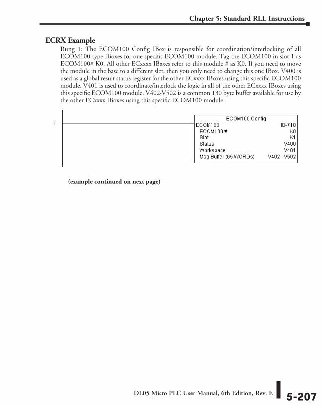
DL05 Micro PLC User Manual, 6th Edition, Rev. E 5-207
Chapter 5: Standard RLL Instructions
ECRX ExampleRung 1: The ECOM100 Config IBox is responsible for coordination/interlocking of all ECOM100 type IBoxes for one specific ECOM100 module. Tag the ECOM100 in slot 1 as ECOM100# K0. All other ECxxxx IBoxes refer to this module # as K0. If you need to move the module in the base to a different slot, then you only need to change this one IBox. V400 is used as a global result status register for the other ECxxxx IBoxes using this specific ECOM100 module. V401 is used to coordinate/interlock the logic in all of the other ECxxxx IBoxes using this specific ECOM100 module. V402-V502 is a common 130 byte buffer available for use by the other ECxxxx IBoxes using this specific ECOM100 module.
(example continued on next page)
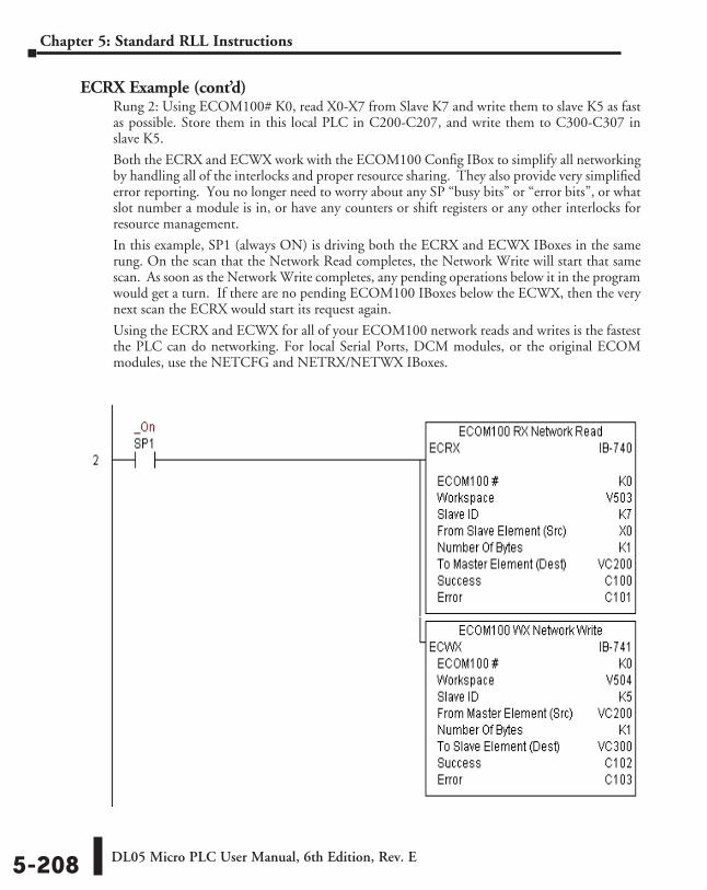
DL05 Micro PLC User Manual, 6th Edition, Rev. E5-208
Chapter 5: Standard RLL Instructions
ECRX Example (cont’d)Rung 2: Using ECOM100# K0, read X0-X7 from Slave K7 and write them to slave K5 as fast as possible. Store them in this local PLC in C200-C207, and write them to C300-C307 in slave K5.
Both the ECRX and ECWX work with the ECOM100 Config IBox to simplify all networking by handling all of the interlocks and proper resource sharing. They also provide very simplified error reporting. You no longer need to worry about any SP “busy bits” or “error bits”, or what slot number a module is in, or have any counters or shift registers or any other interlocks for resource management.
In this example, SP1 (always ON) is driving both the ECRX and ECWX IBoxes in the same rung. On the scan that the Network Read completes, the Network Write will start that same scan. As soon as the Network Write completes, any pending operations below it in the program would get a turn. If there are no pending ECOM100 IBoxes below the ECWX, then the very next scan the ECRX would start its request again.
Using the ECRX and ECWX for all of your ECOM100 network reads and writes is the fastest the PLC can do networking. For local Serial Ports, DCM modules, or the original ECOM modules, use the NETCFG and NETRX/NETWX IBoxes.
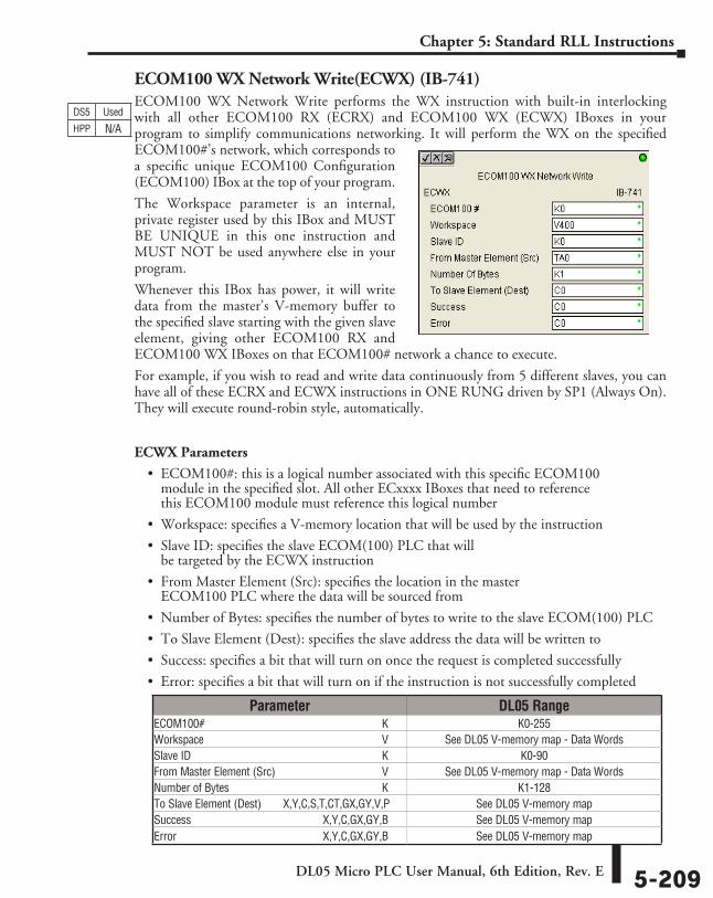
DL05 Micro PLC User Manual, 6th Edition, Rev. E 5-209
Chapter 5: Standard RLL Instructions
ECOM100 WX Network Write(ECWX) (IB-741)ECOM100 WX Network Write performs the WX instruction with built-in interlocking with all other ECOM100 RX (ECRX) and ECOM100 WX (ECWX) IBoxes in your program to simplify communications networking. It will perform the WX on the specified ECOM100#’s network, which corresponds to a specific unique ECOM100 Configuration (ECOM100) IBox at the top of your program.
The Workspace parameter is an internal, private register used by this IBox and MUST BE UNIQUE in this one instruction and MUST NOT be used anywhere else in your program.
Whenever this IBox has power, it will write data from the master’s V-memory buffer to the specified slave starting with the given slave element, giving other ECOM100 RX and ECOM100 WX IBoxes on that ECOM100# network a chance to execute.
For example, if you wish to read and write data continuously from 5 different slaves, you can have all of these ECRX and ECWX instructions in ONE RUNG driven by SP1 (Always On). They will execute round-robin style, automatically.
ECWX Parameters
• ECOM100#: this is a logical number associated with this specific ECOM100 module in the specified slot. All other ECxxxx IBoxes that need to reference this ECOM100 module must reference this logical number
• Workspace: specifies a V-memory location that will be used by the instruction
• Slave ID: specifies the slave ECOM(100) PLC that will be targeted by the ECWX instruction
• From Master Element (Src): specifies the location in the master ECOM100 PLC where the data will be sourced from
• Number of Bytes: specifies the number of bytes to write to the slave ECOM(100) PLC
• To Slave Element (Dest): specifies the slave address the data will be written to
• Success: specifies a bit that will turn on once the request is completed successfully
• Error: specifies a bit that will turn on if the instruction is not successfully completed
DS5 Used
HPP N/A
Parameter DL05 RangeECOM100# ⸠⸠⸠⸠⸠⸠⸠⸠⸠⸠⸠⸠⸠⸠⸠⸠⸠⸠⸠⸠⸠⸠⸠⸠⸠⸠⸠⸠⸠⸠⸠⸠⸠⸠⸠⸠⸠⸠⸠⸠⸠⸠⸠⸠⸠⸠⸠⸠⸠⸠⸠⸠⸠⸠⸠⸠⸠⸠⸠⸠⸠⸠ K K0-255Workspace ⸠⸠⸠⸠⸠⸠⸠⸠⸠⸠⸠⸠⸠⸠⸠⸠⸠⸠⸠⸠⸠⸠⸠⸠⸠⸠⸠⸠⸠⸠⸠⸠⸠⸠⸠⸠⸠⸠⸠⸠⸠⸠⸠⸠⸠⸠⸠⸠⸠⸠⸠⸠⸠⸠⸠⸠⸠⸠⸠⸠⸠⸠ V See DL05 V-memory map - Data WordsSlave ID ⸠⸠⸠⸠⸠⸠⸠⸠⸠⸠⸠⸠⸠⸠⸠⸠⸠⸠⸠⸠⸠⸠⸠⸠⸠⸠⸠⸠⸠⸠⸠⸠⸠⸠⸠⸠⸠⸠⸠⸠⸠⸠⸠⸠⸠⸠⸠⸠⸠⸠⸠⸠⸠⸠⸠⸠⸠⸠⸠⸠⸠⸠⸠⸠⸠⸠⸠ K K0-90From Master Element (Src) ⸠⸠⸠⸠⸠⸠⸠⸠⸠⸠⸠⸠⸠⸠⸠⸠⸠⸠⸠⸠⸠⸠⸠⸠⸠⸠⸠⸠⸠⸠⸠⸠⸠⸠⸠⸠ V See DL05 V-memory map - Data WordsNumber of Bytes ⸠⸠⸠⸠⸠⸠⸠⸠⸠⸠⸠⸠⸠⸠⸠⸠⸠⸠⸠⸠⸠⸠⸠⸠⸠⸠⸠⸠⸠⸠⸠⸠⸠⸠⸠⸠⸠⸠⸠⸠⸠⸠⸠⸠⸠⸠⸠⸠⸠⸠⸠⸠⸠ K K1-128To Slave Element (Dest) ⸠⸠⸠⸠⸠X,Y,C,S,T,CT,GX,GY,V,P See DL05 V-memory mapSuccess ⸠⸠⸠⸠⸠⸠⸠⸠⸠⸠⸠⸠⸠⸠⸠⸠⸠⸠⸠⸠⸠⸠⸠⸠⸠⸠⸠⸠⸠⸠⸠⸠⸠⸠⸠⸠⸠⸠⸠⸠⸠⸠⸠⸠⸠ X,Y,C,GX,GY,B See DL05 V-memory mapError ⸠⸠⸠⸠⸠⸠⸠⸠⸠⸠⸠⸠⸠⸠⸠⸠⸠⸠⸠⸠⸠⸠⸠⸠⸠⸠⸠⸠⸠⸠⸠⸠⸠⸠⸠⸠⸠⸠⸠⸠⸠⸠⸠⸠⸠⸠⸠⸠⸠⸠ X,Y,C,GX,GY,B See DL05 V-memory map
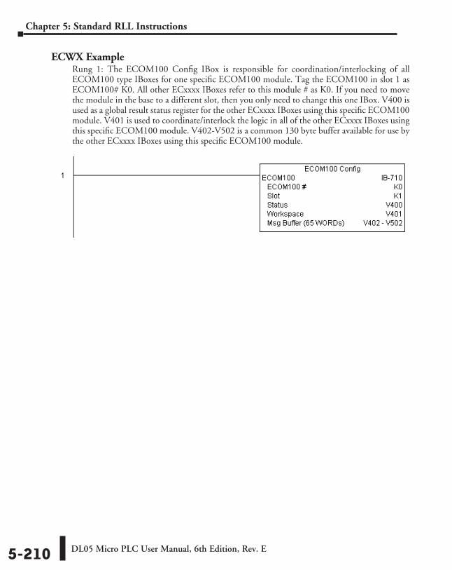
DL05 Micro PLC User Manual, 6th Edition, Rev. E5-210
Chapter 5: Standard RLL Instructions
ECWX ExampleRung 1: The ECOM100 Config IBox is responsible for coordination/interlocking of all ECOM100 type IBoxes for one specific ECOM100 module. Tag the ECOM100 in slot 1 as ECOM100# K0. All other ECxxxx IBoxes refer to this module # as K0. If you need to move the module in the base to a different slot, then you only need to change this one IBox. V400 is used as a global result status register for the other ECxxxx IBoxes using this specific ECOM100 module. V401 is used to coordinate/interlock the logic in all of the other ECxxxx IBoxes using this specific ECOM100 module. V402-V502 is a common 130 byte buffer available for use by the other ECxxxx IBoxes using this specific ECOM100 module.
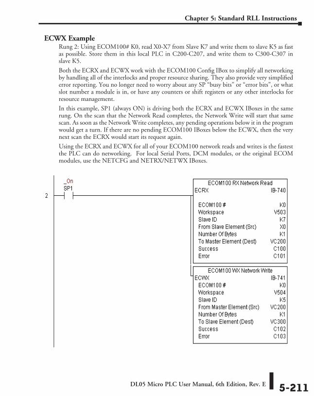
DL05 Micro PLC User Manual, 6th Edition, Rev. E 5-211
Chapter 5: Standard RLL Instructions
ECWX ExampleRung 2: Using ECOM100# K0, read X0-X7 from Slave K7 and write them to slave K5 as fast as possible. Store them in this local PLC in C200-C207, and write them to C300-C307 in slave K5.
Both the ECRX and ECWX work with the ECOM100 Config IBox to simplify all networking by handling all of the interlocks and proper resource sharing. They also provide very simplified error reporting. You no longer need to worry about any SP “busy bits” or “error bits”, or what slot number a module is in, or have any counters or shift registers or any other interlocks for resource management.
In this example, SP1 (always ON) is driving both the ECRX and ECWX IBoxes in the same rung. On the scan that the Network Read completes, the Network Write will start that same scan. As soon as the Network Write completes, any pending operations below it in the program would get a turn. If there are no pending ECOM100 IBoxes below the ECWX, then the very next scan the ECRX would start its request again.
Using the ECRX and ECWX for all of your ECOM100 network reads and writes is the fastest the PLC can do networking. For local Serial Ports, DCM modules, or the original ECOM modules, use the NETCFG and NETRX/NETWX IBoxes.
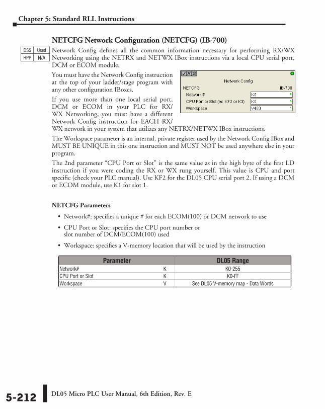
DL05 Micro PLC User Manual, 6th Edition, Rev. E5-212
Chapter 5: Standard RLL Instructions
NETCFG Network Configuration (NETCFG) (IB-700)Network Config defines all the common information necessary for performing RX/WX Networking using the NETRX and NETWX IBox instructions via a local CPU serial port, DCM or ECOM module.
You must have the Network Config instruction at the top of your ladder/stage program with any other configuration IBoxes.
If you use more than one local serial port, DCM or ECOM in your PLC for RX/WX Networking, you must have a different Network Config instruction for EACH RX/WX network in your system that utilizes any NETRX/NETWX IBox instructions.
The Workspace parameter is an internal, private register used by the Network Config IBox and MUST BE UNIQUE in this one instruction and MUST NOT be used anywhere else in your program.
The 2nd parameter “CPU Port or Slot” is the same value as in the high byte of the first LD instruction if you were coding the RX or WX rung yourself. This value is CPU and port specific (check your PLC manual). Use KF2 for the DL05 CPU serial port 2. If using a DCM or ECOM module, use K1 for slot 1.
NETCFG Parameters
• Network#: specifies a unique # for each ECOM(100) or DCM network to use
• CPU Port or Slot: specifies the CPU port number or slot number of DCM/ECOM(100) used
• Workspace: specifies a V-memory location that will be used by the instruction
DS5 Used
HPP N/A
Parameter DL05 RangeNetwork# ⸠⸠⸠⸠⸠⸠⸠⸠⸠⸠⸠⸠⸠⸠⸠⸠⸠⸠⸠⸠⸠⸠⸠⸠⸠⸠⸠⸠⸠⸠⸠⸠⸠⸠⸠⸠⸠⸠⸠⸠⸠⸠⸠⸠⸠⸠⸠⸠⸠⸠⸠⸠⸠⸠⸠⸠⸠⸠⸠⸠⸠⸠⸠⸠⸠ K K0-255CPU Port or Slot ⸠⸠⸠⸠⸠⸠⸠⸠⸠⸠⸠⸠⸠⸠⸠⸠⸠⸠⸠⸠⸠⸠⸠⸠⸠⸠⸠⸠⸠⸠⸠⸠⸠⸠⸠⸠⸠⸠⸠⸠⸠⸠⸠⸠⸠⸠⸠⸠⸠⸠⸠⸠⸠ K K0-FFWorkspace ⸠⸠⸠⸠⸠⸠⸠⸠⸠⸠⸠⸠⸠⸠⸠⸠⸠⸠⸠⸠⸠⸠⸠⸠⸠⸠⸠⸠⸠⸠⸠⸠⸠⸠⸠⸠⸠⸠⸠⸠⸠⸠⸠⸠⸠⸠⸠⸠⸠⸠⸠⸠⸠⸠⸠⸠⸠⸠⸠⸠⸠⸠ V See DL05 V-memory map - Data Words
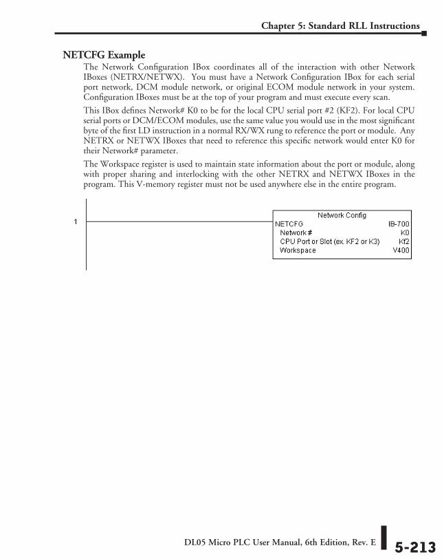
DL05 Micro PLC User Manual, 6th Edition, Rev. E 5-213
Chapter 5: Standard RLL Instructions
NETCFG ExampleThe Network Configuration IBox coordinates all of the interaction with other Network IBoxes (NETRX/NETWX). You must have a Network Configuration IBox for each serial port network, DCM module network, or original ECOM module network in your system. Configuration IBoxes must be at the top of your program and must execute every scan.
This IBox defines Network# K0 to be for the local CPU serial port #2 (KF2). For local CPU serial ports or DCM/ECOM modules, use the same value you would use in the most significant byte of the first LD instruction in a normal RX/WX rung to reference the port or module. Any NETRX or NETWX IBoxes that need to reference this specific network would enter K0 for their Network# parameter.
The Workspace register is used to maintain state information about the port or module, along with proper sharing and interlocking with the other NETRX and NETWX IBoxes in the program. This V-memory register must not be used anywhere else in the entire program.
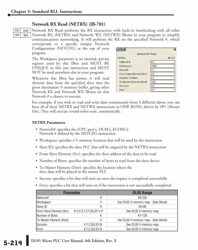
DL05 Micro PLC User Manual, 6th Edition, Rev. E5-214
Chapter 5: Standard RLL Instructions
Network RX Read (NETRX) (IB-701)Network RX Read performs the RX instruction with built-in interlocking with all other Network RX (NETRX) and Network WX (NETWX) IBoxes in your program to simplify communications networking. It will perform the RX on the specified Network #, which corresponds to a specific unique Network Configuration (NETCFG) at the top of your program.
The Workspace parameter is an internal, private register used by this IBox and MUST BE UNIQUE in this one instruction and MUST NOT be used anywhere else in your program.
Whenever this IBox has power, it will read element data from the specified slave into the given destination V-memory buffer, giving other Network RX and Network WX IBoxes on that Network # a chance to execute.
For example, if you wish to read and write data continuously from 5 different slaves, you can have all of these NETRX and NETWX instructions in ONE RUNG driven by SP1 (Always On). They will execute round-robin style, automatically.
NETRX Parameters
• Network#: specifies the (CPU port’s, DCM’s, ECOM’s) Network # defined by the NETCFG instruction
• Workspace: specifies a V-memory location that will be used by the instruction
• Slave ID: specifies the slave PLC that will be targeted by the NETRX instruction
• From Slave Element (Src): specifies the slave address of the data to be read
• Number of Bytes: specifies the number of bytes to read from the slave device
• To Master Element (Dest): specifies the location where the slave data will be placed in the master PLC
• Success: specifies a bit that will turn on once the request is completed successfully
• Error: specifies a bit that will turn on if the instruction is not successfully completed
DS5 Used
HPP N/A
Parameter DL05 RangeNetwork# ⸠⸠⸠⸠⸠⸠⸠⸠⸠⸠⸠⸠⸠⸠⸠⸠⸠⸠⸠⸠⸠⸠⸠⸠⸠⸠⸠⸠⸠⸠⸠⸠⸠⸠⸠⸠⸠⸠⸠⸠⸠⸠⸠⸠⸠⸠⸠⸠⸠⸠⸠⸠⸠⸠⸠⸠⸠⸠⸠⸠⸠⸠⸠⸠⸠ K K0-255Workspace ⸠⸠⸠⸠⸠⸠⸠⸠⸠⸠⸠⸠⸠⸠⸠⸠⸠⸠⸠⸠⸠⸠⸠⸠⸠⸠⸠⸠⸠⸠⸠⸠⸠⸠⸠⸠⸠⸠⸠⸠⸠⸠⸠⸠⸠⸠⸠⸠⸠⸠⸠⸠⸠⸠⸠⸠⸠⸠⸠⸠⸠⸠ V See DL05 V-memory map - Data WordsSlave ID ⸠⸠⸠⸠⸠⸠⸠⸠⸠⸠⸠⸠⸠⸠⸠⸠⸠⸠⸠⸠⸠⸠⸠⸠⸠⸠⸠⸠⸠⸠⸠⸠⸠⸠⸠⸠⸠⸠⸠⸠⸠⸠⸠⸠⸠⸠⸠⸠⸠⸠⸠⸠⸠⸠⸠⸠⸠⸠⸠⸠⸠⸠⸠⸠⸠⸠⸠ K K0-90From Slave Element (Src) ⸠⸠⸠ X,Y,C,S,T,CT,GX,GY,V,P See DL05 V-memory mapNumber of Bytes ⸠⸠⸠⸠⸠⸠⸠⸠⸠⸠⸠⸠⸠⸠⸠⸠⸠⸠⸠⸠⸠⸠⸠⸠⸠⸠⸠⸠⸠⸠⸠⸠⸠⸠⸠⸠⸠⸠⸠⸠⸠⸠⸠⸠⸠⸠⸠⸠⸠⸠⸠⸠⸠ K K1-128To Master Element (Dest) ⸠⸠⸠⸠⸠⸠⸠⸠⸠⸠⸠⸠⸠⸠⸠⸠⸠⸠⸠⸠⸠⸠⸠⸠⸠⸠⸠⸠⸠⸠⸠⸠⸠⸠⸠⸠⸠⸠ V See DL05 V-memory map - Data WordsSuccess ⸠⸠⸠⸠⸠⸠⸠⸠⸠⸠⸠⸠⸠⸠⸠⸠⸠⸠⸠⸠⸠⸠⸠⸠⸠⸠⸠⸠⸠⸠⸠⸠⸠⸠⸠⸠⸠⸠⸠⸠⸠⸠⸠⸠⸠ X,Y,C,GX,GY,B See DL05 V-memory mapError ⸠⸠⸠⸠⸠⸠⸠⸠⸠⸠⸠⸠⸠⸠⸠⸠⸠⸠⸠⸠⸠⸠⸠⸠⸠⸠⸠⸠⸠⸠⸠⸠⸠⸠⸠⸠⸠⸠⸠⸠⸠⸠⸠⸠⸠⸠⸠⸠⸠⸠ X,Y,C,GX,GY,B See DL05 V-memory map
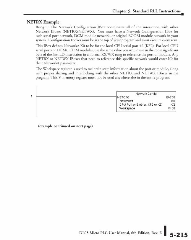
DL05 Micro PLC User Manual, 6th Edition, Rev. E 5-215
Chapter 5: Standard RLL Instructions
NETRX ExampleRung 1: The Network Configuration IBox coordinates all of the interaction with other Network IBoxes (NETRX/NETWX). You must have a Network Configuration IBox for each serial port network, DCM module network, or original ECOM module network in your system. Configuration IBoxes must be at the top of your program and must execute every scan.
This IBox defines Network# K0 to be for the local CPU serial port #2 (KF2). For local CPU serial ports or DCM/ECOM modules, use the same value you would use in the most significant byte of the first LD instruction in a normal RX/WX rung to reference the port or module. Any NETRX or NETWX IBoxes that need to reference this specific network would enter K0 for their Network# parameter.
The Workspace register is used to maintain state information about the port or module, along with proper sharing and interlocking with the other NETRX and NETWX IBoxes in the program. This V-memory register must not be used anywhere else in the entire program.
(example continued on next page)
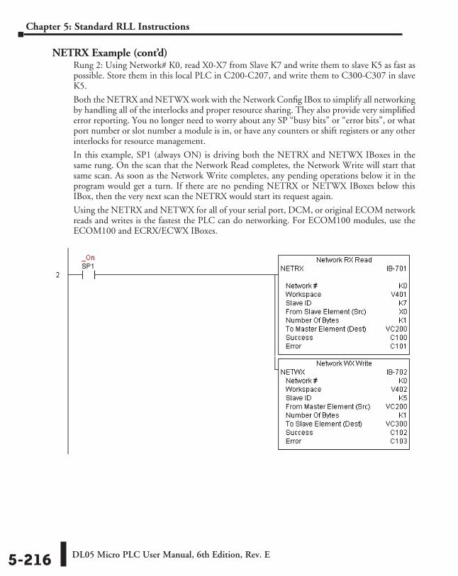
DL05 Micro PLC User Manual, 6th Edition, Rev. E5-216
Chapter 5: Standard RLL Instructions
NETRX Example (cont’d)Rung 2: Using Network# K0, read X0-X7 from Slave K7 and write them to slave K5 as fast as possible. Store them in this local PLC in C200-C207, and write them to C300-C307 in slave K5.
Both the NETRX and NETWX work with the Network Config IBox to simplify all networking by handling all of the interlocks and proper resource sharing. They also provide very simplified error reporting. You no longer need to worry about any SP “busy bits” or “error bits”, or what port number or slot number a module is in, or have any counters or shift registers or any other interlocks for resource management.
In this example, SP1 (always ON) is driving both the NETRX and NETWX IBoxes in the same rung. On the scan that the Network Read completes, the Network Write will start that same scan. As soon as the Network Write completes, any pending operations below it in the program would get a turn. If there are no pending NETRX or NETWX IBoxes below this IBox, then the very next scan the NETRX would start its request again.
Using the NETRX and NETWX for all of your serial port, DCM, or original ECOM network reads and writes is the fastest the PLC can do networking. For ECOM100 modules, use the ECOM100 and ECRX/ECWX IBoxes.
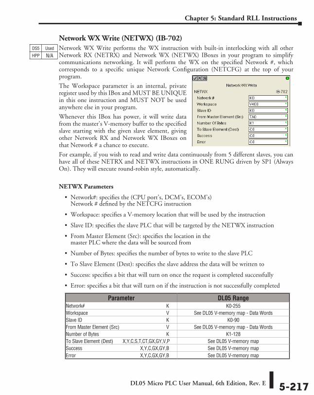
DL05 Micro PLC User Manual, 6th Edition, Rev. E 5-217
Chapter 5: Standard RLL Instructions
Network WX Write (NETWX) (IB-702)Network WX Write performs the WX instruction with built-in interlocking with all other Network RX (NETRX) and Network WX (NETWX) IBoxes in your program to simplify communications networking. It will perform the WX on the specified Network #, which corresponds to a specific unique Network Configuration (NETCFG) at the top of your program.
The Workspace parameter is an internal, private register used by this IBox and MUST BE UNIQUE in this one instruction and MUST NOT be used anywhere else in your program.
Whenever this IBox has power, it will write data from the master’s V-memory buffer to the specified slave starting with the given slave element, giving other Network RX and Network WX IBoxes on that Network # a chance to execute.
For example, if you wish to read and write data continuously from 5 different slaves, you can have all of these NETRX and NETWX instructions in ONE RUNG driven by SP1 (Always On). They will execute round-robin style, automatically.
NETWX Parameters
• Network#: specifies the (CPU port’s, DCM’s, ECOM’s) Network # defined by the NETCFG instruction
• Workspace: specifies a V-memory location that will be used by the instruction
• Slave ID: specifies the slave PLC that will be targeted by the NETWX instruction
• From Master Element (Src): specifies the location in the master PLC where the data will be sourced from
• Number of Bytes: specifies the number of bytes to write to the slave PLC
• To Slave Element (Dest): specifies the slave address the data will be written to
• Success: specifies a bit that will turn on once the request is completed successfully
• Error: specifies a bit that will turn on if the instruction is not successfully completed
DS5 Used
HPP N/A
Parameter DL05 RangeNetwork# ⸠⸠⸠⸠⸠⸠⸠⸠⸠⸠⸠⸠⸠⸠⸠⸠⸠⸠⸠⸠⸠⸠⸠⸠⸠⸠⸠⸠⸠⸠⸠⸠⸠⸠⸠⸠⸠⸠⸠⸠⸠⸠⸠⸠⸠⸠⸠⸠⸠⸠⸠⸠⸠⸠⸠⸠⸠⸠⸠⸠⸠⸠⸠⸠⸠ K K0-255Workspace ⸠⸠⸠⸠⸠⸠⸠⸠⸠⸠⸠⸠⸠⸠⸠⸠⸠⸠⸠⸠⸠⸠⸠⸠⸠⸠⸠⸠⸠⸠⸠⸠⸠⸠⸠⸠⸠⸠⸠⸠⸠⸠⸠⸠⸠⸠⸠⸠⸠⸠⸠⸠⸠⸠⸠⸠⸠⸠⸠⸠⸠⸠ V See DL05 V-memory map - Data WordsSlave ID ⸠⸠⸠⸠⸠⸠⸠⸠⸠⸠⸠⸠⸠⸠⸠⸠⸠⸠⸠⸠⸠⸠⸠⸠⸠⸠⸠⸠⸠⸠⸠⸠⸠⸠⸠⸠⸠⸠⸠⸠⸠⸠⸠⸠⸠⸠⸠⸠⸠⸠⸠⸠⸠⸠⸠⸠⸠⸠⸠⸠⸠⸠⸠⸠⸠⸠⸠ K K0-90From Master Element (Src) ⸠⸠⸠⸠⸠⸠⸠⸠⸠⸠⸠⸠⸠⸠⸠⸠⸠⸠⸠⸠⸠⸠⸠⸠⸠⸠⸠⸠⸠⸠⸠⸠⸠⸠⸠⸠ V See DL05 V-memory map - Data WordsNumber of Bytes ⸠⸠⸠⸠⸠⸠⸠⸠⸠⸠⸠⸠⸠⸠⸠⸠⸠⸠⸠⸠⸠⸠⸠⸠⸠⸠⸠⸠⸠⸠⸠⸠⸠⸠⸠⸠⸠⸠⸠⸠⸠⸠⸠⸠⸠⸠⸠⸠⸠⸠⸠⸠⸠ K K1-128To Slave Element (Dest) ⸠⸠⸠⸠⸠X,Y,C,S,T,CT,GX,GY,V,P See DL05 V-memory mapSuccess ⸠⸠⸠⸠⸠⸠⸠⸠⸠⸠⸠⸠⸠⸠⸠⸠⸠⸠⸠⸠⸠⸠⸠⸠⸠⸠⸠⸠⸠⸠⸠⸠⸠⸠⸠⸠⸠⸠⸠⸠⸠⸠⸠⸠⸠ X,Y,C,GX,GY,B See DL05 V-memory mapError ⸠⸠⸠⸠⸠⸠⸠⸠⸠⸠⸠⸠⸠⸠⸠⸠⸠⸠⸠⸠⸠⸠⸠⸠⸠⸠⸠⸠⸠⸠⸠⸠⸠⸠⸠⸠⸠⸠⸠⸠⸠⸠⸠⸠⸠⸠⸠⸠⸠⸠ X,Y,C,GX,GY,B See DL05 V-memory map
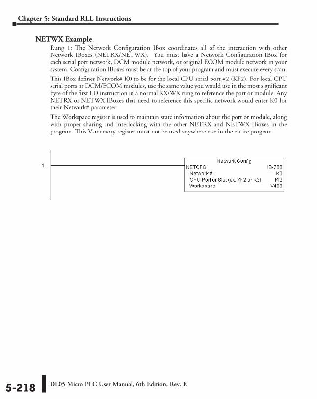
DL05 Micro PLC User Manual, 6th Edition, Rev. E5-218
Chapter 5: Standard RLL Instructions
NETWX ExampleRung 1: The Network Configuration IBox coordinates all of the interaction with other Network IBoxes (NETRX/NETWX). You must have a Network Configuration IBox for each serial port network, DCM module network, or original ECOM module network in your system. Configuration IBoxes must be at the top of your program and must execute every scan.
This IBox defines Network# K0 to be for the local CPU serial port #2 (KF2). For local CPU serial ports or DCM/ECOM modules, use the same value you would use in the most significant byte of the first LD instruction in a normal RX/WX rung to reference the port or module. Any NETRX or NETWX IBoxes that need to reference this specific network would enter K0 for their Network# parameter.
The Workspace register is used to maintain state information about the port or module, along with proper sharing and interlocking with the other NETRX and NETWX IBoxes in the program. This V-memory register must not be used anywhere else in the entire program.
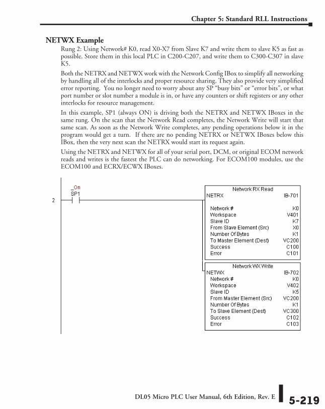
DL05 Micro PLC User Manual, 6th Edition, Rev. E 5-219
Chapter 5: Standard RLL Instructions
NETWX ExampleRung 2: Using Network# K0, read X0-X7 from Slave K7 and write them to slave K5 as fast as possible. Store them in this local PLC in C200-C207, and write them to C300-C307 in slave K5.
Both the NETRX and NETWX work with the Network Config IBox to simplify all networking by handling all of the interlocks and proper resource sharing. They also provide very simplified error reporting. You no longer need to worry about any SP “busy bits” or “error bits”, or what port number or slot number a module is in, or have any counters or shift registers or any other interlocks for resource management.
In this example, SP1 (always ON) is driving both the NETRX and NETWX IBoxes in the same rung. On the scan that the Network Read completes, the Network Write will start that same scan. As soon as the Network Write completes, any pending operations below it in the program would get a turn. If there are no pending NETRX or NETWX IBoxes below this IBox, then the very next scan the NETRX would start its request again.
Using the NETRX and NETWX for all of your serial port, DCM, or original ECOM network reads and writes is the fastest the PLC can do networking. For ECOM100 modules, use the ECOM100 and ECRX/ECWX IBoxes.
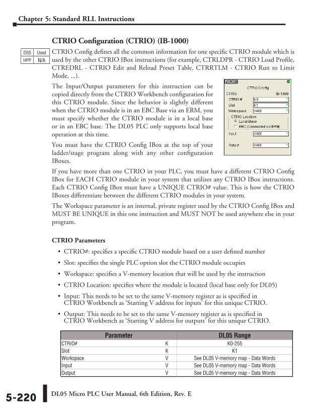
DL05 Micro PLC User Manual, 6th Edition, Rev. E5-220
Chapter 5: Standard RLL Instructions
CTRIO Configuration (CTRIO) (IB-1000)CTRIO Config defines all the common information for one specific CTRIO module which is used by the other CTRIO IBox instructions (for example, CTRLDPR - CTRIO Load Profile, CTREDRL - CTRIO Edit and Reload Preset Table, CTRRTLM - CTRIO Run to Limit Mode, ...).
The Input/Output parameters for this instruction can be copied directly from the CTRIO Workbench configuration for this CTRIO module. Since the behavior is slightly different when the CTRIO module is in an EBC Base via an ERM, you must specify whether the CTRIO module is in a local base or in an EBC base. The DL05 PLC only supports local base operation at this time.
You must have the CTRIO Config IBox at the top of your ladder/stage program along with any other configuration IBoxes.
If you have more than one CTRIO in your PLC, you must have a different CTRIO Config IBox for EACH CTRIO module in your system that utilizes any CTRIO IBox instructions. Each CTRIO Config IBox must have a UNIQUE CTRIO# value. This is how the CTRIO IBoxes differentiate between the different CTRIO modules in your system.
The Workspace parameter is an internal, private register used by the CTRIO Config IBox and MUST BE UNIQUE in this one instruction and MUST NOT be used anywhere else in your program.
CTRIO Parameters
• CTRIO#: specifies a specific CTRIO module based on a user defined number
• Slot: specifies the single PLC option slot the CTRIO module occupies
• Workspace: specifies a V-memory location that will be used by the instruction
• CTRIO Location: specifies where the module is located (local base only for DL05)
• Input: This needs to be set to the same V-memory register as is specified in CTRIO Workbench as ‘Starting V address for inputs’ for this unique CTRIO.
• Output: This needs to be set to the same V-memory register as is specified in CTRIO Workbench as ‘Starting V address for outputs’ for this unique CTRIO.
DS5 Used
HPP N/A
Parameter DL05 RangeCTRIO# ⸠⸠⸠⸠⸠⸠⸠⸠⸠⸠⸠⸠⸠⸠⸠⸠⸠⸠⸠⸠⸠⸠⸠⸠⸠⸠⸠⸠⸠⸠⸠⸠⸠⸠⸠⸠⸠⸠⸠⸠⸠⸠⸠⸠⸠⸠⸠⸠⸠⸠⸠⸠⸠⸠⸠⸠⸠⸠⸠⸠⸠⸠⸠⸠⸠⸠⸠⸠ K K0-255Slot ⸠⸠⸠⸠⸠⸠⸠⸠⸠⸠⸠⸠⸠⸠⸠⸠⸠⸠⸠⸠⸠⸠⸠⸠⸠⸠⸠⸠⸠⸠⸠⸠⸠⸠⸠⸠⸠⸠⸠⸠⸠⸠⸠⸠⸠⸠⸠⸠⸠⸠⸠⸠⸠⸠⸠⸠⸠⸠⸠⸠⸠⸠⸠⸠⸠⸠⸠⸠⸠⸠⸠⸠⸠⸠ K K1Workspace ⸠⸠⸠⸠⸠⸠⸠⸠⸠⸠⸠⸠⸠⸠⸠⸠⸠⸠⸠⸠⸠⸠⸠⸠⸠⸠⸠⸠⸠⸠⸠⸠⸠⸠⸠⸠⸠⸠⸠⸠⸠⸠⸠⸠⸠⸠⸠⸠⸠⸠⸠⸠⸠⸠⸠⸠⸠⸠⸠⸠⸠⸠ V See DL05 V-memory map - Data WordsInput ⸠⸠⸠⸠⸠⸠⸠⸠⸠⸠⸠⸠⸠⸠⸠⸠⸠⸠⸠⸠⸠⸠⸠⸠⸠⸠⸠⸠⸠⸠⸠⸠⸠⸠⸠⸠⸠⸠⸠⸠⸠⸠⸠⸠⸠⸠⸠⸠⸠⸠⸠⸠⸠⸠⸠⸠⸠⸠⸠⸠⸠⸠⸠⸠⸠⸠⸠⸠⸠⸠⸠⸠ V See DL05 V-memory map - Data WordsOutput ⸠⸠⸠⸠⸠⸠⸠⸠⸠⸠⸠⸠⸠⸠⸠⸠⸠⸠⸠⸠⸠⸠⸠⸠⸠⸠⸠⸠⸠⸠⸠⸠⸠⸠⸠⸠⸠⸠⸠⸠⸠⸠⸠⸠⸠⸠⸠⸠⸠⸠⸠⸠⸠⸠⸠⸠⸠⸠⸠⸠⸠⸠⸠⸠⸠⸠⸠⸠⸠ V See DL05 V-memory map - Data Words
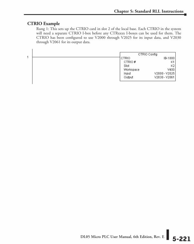
DL05 Micro PLC User Manual, 6th Edition, Rev. E 5-221
Chapter 5: Standard RLL Instructions
CTRIO ExampleRung 1: This sets up the CTRIO card in slot 2 of the local base. Each CTRIO in the system will need a separate CTRIO I-box before any CTRxxxx I-boxes can be used for them. The CTRIO has been configured to use V2000 through V2025 for its input data, and V2030 through V2061 for its output data.
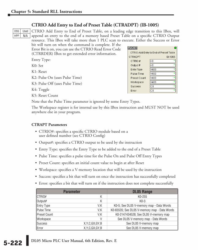
DL05 Micro PLC User Manual, 6th Edition, Rev. E5-222
Chapter 5: Standard RLL Instructions
CTRIO Add Entry to End of Preset Table (CTRADPT) (IB-1005)CTRIO Add Entry to End of Preset Table, on a leading edge transition to this IBox, will append an entry to the end of a memory based Preset Table on a specific CTRIO Output resource. This IBox will take more than 1 PLC scan to execute. Either the Success or Error bit will turn on when the command is complete. If the Error Bit is on, you can use the CTRIO Read Error Code (CTRRDER) IBox to get extended error information.
Entry Type:
K0: Set
K1: Reset
K2: Pulse On (uses Pulse Time)
K3: Pulse Off (uses Pulse Time)
K4: Toggle
K5: Reset Count
Note that the Pulse Time parameter is ignored by some Entry Types.
The Workspace register is for internal use by this IBox instruction and MUST NOT be used anywhere else in your program.
CTRAPT Parameters
• CTRIO#: specifies a specific CTRIO module based on a user defined number (see CTRIO Config)
• Output#: specifies a CTRIO output to be used by the instruction
• Entry Type: specifies the Entry Type to be added to the end of a Preset Table
• Pulse Time: specifies a pulse time for the Pulse On and Pulse Off Entry Types
• Preset Count: specifies an initial count value to begin at after Reset
• Workspace: specifies a V-memory location that will be used by the instruction
• Success: specifies a bit that will turn on once the instruction has successfully completed
• Error: specifies a bit that will turn on if the instruction does not complete successfully
DS5 Used
HPP N/A
Parameter DL05 RangeCTRIO# ⸠⸠⸠⸠⸠⸠⸠⸠⸠⸠⸠⸠⸠⸠⸠⸠⸠⸠⸠⸠⸠⸠⸠⸠⸠⸠⸠⸠⸠⸠⸠⸠⸠⸠⸠⸠⸠⸠⸠⸠⸠⸠⸠⸠⸠⸠⸠⸠⸠⸠⸠⸠⸠⸠⸠⸠⸠⸠⸠⸠⸠⸠⸠⸠⸠⸠⸠⸠ K K0-255Output# ⸠⸠⸠⸠⸠⸠⸠⸠⸠⸠⸠⸠⸠⸠⸠⸠⸠⸠⸠⸠⸠⸠⸠⸠⸠⸠⸠⸠⸠⸠⸠⸠⸠⸠⸠⸠⸠⸠⸠⸠⸠⸠⸠⸠⸠⸠⸠⸠⸠⸠⸠⸠⸠⸠⸠⸠⸠⸠⸠⸠⸠⸠⸠⸠⸠⸠⸠ K K0-3Entry Type ⸠⸠⸠⸠⸠⸠⸠⸠⸠⸠⸠⸠⸠⸠⸠⸠⸠⸠⸠⸠⸠⸠⸠⸠⸠⸠⸠⸠⸠⸠⸠⸠⸠⸠⸠⸠⸠⸠⸠⸠⸠⸠⸠⸠⸠⸠⸠⸠⸠⸠⸠⸠⸠⸠⸠⸠⸠⸠⸠⸠V,K K0-5; See DL05 V-memory map - Data WordsPulse Time ⸠⸠⸠⸠⸠⸠⸠⸠⸠⸠⸠⸠⸠⸠⸠⸠⸠⸠⸠⸠⸠⸠⸠⸠⸠⸠⸠⸠⸠⸠⸠⸠⸠⸠⸠⸠⸠⸠⸠⸠⸠⸠⸠⸠⸠⸠⸠⸠⸠⸠⸠⸠⸠⸠⸠⸠⸠⸠⸠V,K K0-65535; See DL05 V-memory map - Data WordsPreset Count ⸠⸠⸠⸠⸠⸠⸠⸠⸠⸠⸠⸠⸠⸠⸠⸠⸠⸠⸠⸠⸠⸠⸠⸠⸠⸠⸠⸠⸠⸠⸠⸠⸠⸠⸠⸠⸠⸠⸠⸠⸠⸠⸠⸠⸠⸠⸠⸠⸠⸠⸠⸠⸠⸠⸠⸠V,K K0-2147434528; See DL05 V-memory mapWorkspace ⸠⸠⸠⸠⸠⸠⸠⸠⸠⸠⸠⸠⸠⸠⸠⸠⸠⸠⸠⸠⸠⸠⸠⸠⸠⸠⸠⸠⸠⸠⸠⸠⸠⸠⸠⸠⸠⸠⸠⸠⸠⸠⸠⸠⸠⸠⸠⸠⸠⸠⸠⸠⸠⸠⸠⸠⸠⸠⸠⸠⸠⸠ V See DL05 V-memory map - Data WordsSuccess ⸠⸠⸠⸠⸠⸠⸠⸠⸠⸠⸠⸠⸠⸠⸠⸠⸠⸠⸠⸠⸠⸠⸠⸠⸠⸠⸠⸠⸠⸠⸠⸠⸠⸠⸠⸠⸠⸠⸠⸠⸠⸠⸠⸠⸠ X,Y,C,GX,GY,B See DL05 V-memory mapError ⸠⸠⸠⸠⸠⸠⸠⸠⸠⸠⸠⸠⸠⸠⸠⸠⸠⸠⸠⸠⸠⸠⸠⸠⸠⸠⸠⸠⸠⸠⸠⸠⸠⸠⸠⸠⸠⸠⸠⸠⸠⸠⸠⸠⸠⸠⸠⸠⸠⸠ X,Y,C,GX,GY,B See DL05 V-memory map
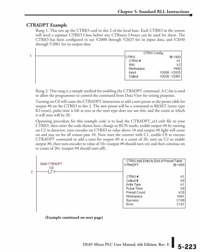
DL05 Micro PLC User Manual, 6th Edition, Rev. E 5-223
Chapter 5: Standard RLL Instructions
CTRADPT ExampleRung 1: This sets up the CTRIO card in slot 2 of the local base. Each CTRIO in the system will need a separate CTRIO I-box before any CTRxxxx I-boxes can be used for them. The CTRIO has been configured to use V2000 through V2025 for its input data, and V2030 through V2061 for its output data.
Rung 2: This rung is a sample method for enabling the CTRADPT command. A C-bit is used to allow the programmer to control the command from Data View for testing purposes.
Turning on C0 will cause the CTRADPT instruction to add a new preset to the preset table for output #0 on the CTRIO in slot 2. The new preset will be a command to RESET (entry type K1=reset), pulse time is left at zero as the reset type does not use this, and the count at which it will reset will be 20.
Operating procedure for this example code is to load the CTRADPT_ex1.cwb file to your CTRIO, then enter the code shown here, change to RUN mode, enable output #0 by turning on C2 in dataview, turn encoder on CTRIO to value above 10 and output #0 light will come on and stay on for all counts past 10. Now reset the counter with C1, enable C0 to execute CTRADPT command to add a reset for output #0 at a count of 20, turn on C2 to enable output #0, then turn encoder to value of 10+ (output #0 should turn on) and then continue on to count of 20+ (output #0 should turn off).
(Example continued on next page)
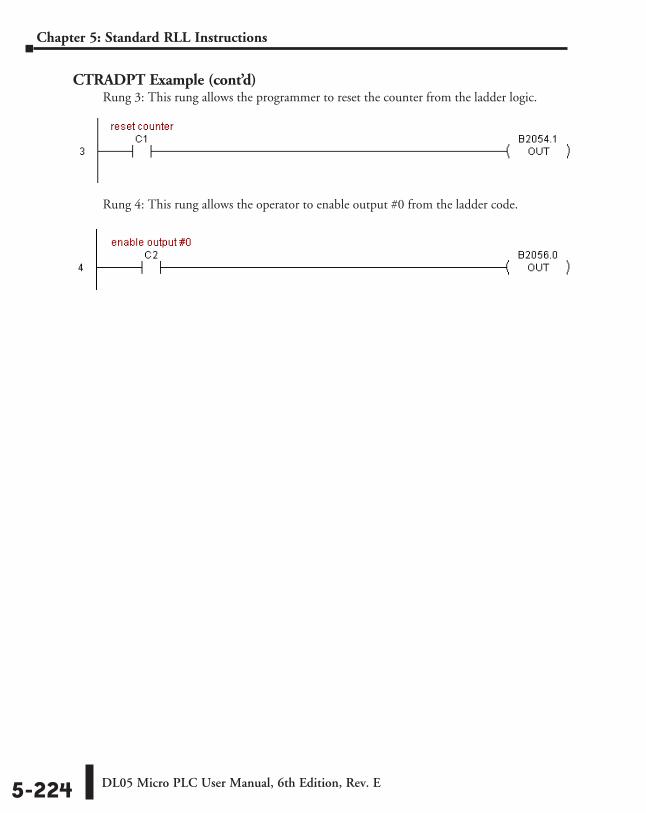
DL05 Micro PLC User Manual, 6th Edition, Rev. E5-224
Chapter 5: Standard RLL Instructions
CTRADPT Example (cont’d)Rung 3: This rung allows the programmer to reset the counter from the ladder logic.
Rung 4: This rung allows the operator to enable output #0 from the ladder code.
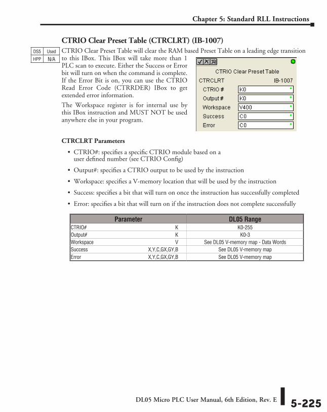
DL05 Micro PLC User Manual, 6th Edition, Rev. E 5-225
Chapter 5: Standard RLL Instructions
CTRIO Clear Preset Table (CTRCLRT) (IB-1007)CTRIO Clear Preset Table will clear the RAM based Preset Table on a leading edge transition to this IBox. This IBox will take more than 1 PLC scan to execute. Either the Success or Error bit will turn on when the command is complete. If the Error Bit is on, you can use the CTRIO Read Error Code (CTRRDER) IBox to get extended error information.
The Workspace register is for internal use by this IBox instruction and MUST NOT be used anywhere else in your program.
CTRCLRT Parameters
• CTRIO#: specifies a specific CTRIO module based on a user defined number (see CTRIO Config)
• Output#: specifies a CTRIO output to be used by the instruction
• Workspace: specifies a V-memory location that will be used by the instruction
• Success: specifies a bit that will turn on once the instruction has successfully completed
• Error: specifies a bit that will turn on if the instruction does not complete successfully
DS5 Used
HPP N/A
Parameter DL05 RangeCTRIO# ⸠⸠⸠⸠⸠⸠⸠⸠⸠⸠⸠⸠⸠⸠⸠⸠⸠⸠⸠⸠⸠⸠⸠⸠⸠⸠⸠⸠⸠⸠⸠⸠⸠⸠⸠⸠⸠⸠⸠⸠⸠⸠⸠⸠⸠⸠⸠⸠⸠⸠⸠⸠⸠⸠⸠⸠⸠⸠⸠⸠⸠⸠⸠⸠⸠⸠⸠⸠ K K0-255Output# ⸠⸠⸠⸠⸠⸠⸠⸠⸠⸠⸠⸠⸠⸠⸠⸠⸠⸠⸠⸠⸠⸠⸠⸠⸠⸠⸠⸠⸠⸠⸠⸠⸠⸠⸠⸠⸠⸠⸠⸠⸠⸠⸠⸠⸠⸠⸠⸠⸠⸠⸠⸠⸠⸠⸠⸠⸠⸠⸠⸠⸠⸠⸠⸠⸠⸠⸠ K K0-3Workspace ⸠⸠⸠⸠⸠⸠⸠⸠⸠⸠⸠⸠⸠⸠⸠⸠⸠⸠⸠⸠⸠⸠⸠⸠⸠⸠⸠⸠⸠⸠⸠⸠⸠⸠⸠⸠⸠⸠⸠⸠⸠⸠⸠⸠⸠⸠⸠⸠⸠⸠⸠⸠⸠⸠⸠⸠⸠⸠⸠⸠⸠⸠ V See DL05 V-memory map - Data WordsSuccess ⸠⸠⸠⸠⸠⸠⸠⸠⸠⸠⸠⸠⸠⸠⸠⸠⸠⸠⸠⸠⸠⸠⸠⸠⸠⸠⸠⸠⸠⸠⸠⸠⸠⸠⸠⸠⸠⸠⸠⸠⸠⸠⸠⸠⸠ X,Y,C,GX,GY,B See DL05 V-memory mapError ⸠⸠⸠⸠⸠⸠⸠⸠⸠⸠⸠⸠⸠⸠⸠⸠⸠⸠⸠⸠⸠⸠⸠⸠⸠⸠⸠⸠⸠⸠⸠⸠⸠⸠⸠⸠⸠⸠⸠⸠⸠⸠⸠⸠⸠⸠⸠⸠⸠⸠ X,Y,C,GX,GY,B See DL05 V-memory map
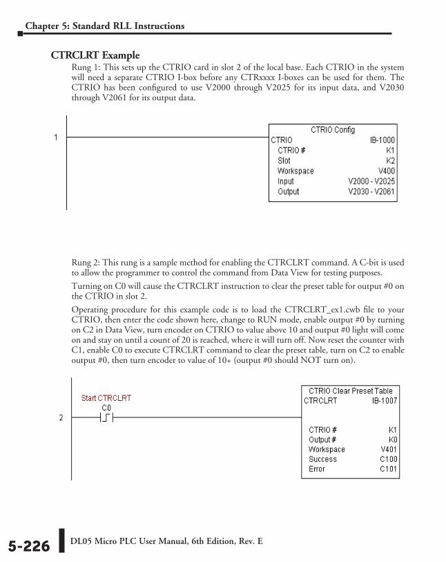
DL05 Micro PLC User Manual, 6th Edition, Rev. E5-226
Chapter 5: Standard RLL Instructions
CTRCLRT ExampleRung 1: This sets up the CTRIO card in slot 2 of the local base. Each CTRIO in the system will need a separate CTRIO I-box before any CTRxxxx I-boxes can be used for them. The CTRIO has been configured to use V2000 through V2025 for its input data, and V2030 through V2061 for its output data.
Rung 2: This rung is a sample method for enabling the CTRCLRT command. A C-bit is used to allow the programmer to control the command from Data View for testing purposes.
Turning on C0 will cause the CTRCLRT instruction to clear the preset table for output #0 on the CTRIO in slot 2.
Operating procedure for this example code is to load the CTRCLRT_ex1.cwb file to your CTRIO, then enter the code shown here, change to RUN mode, enable output #0 by turning on C2 in Data View, turn encoder on CTRIO to value above 10 and output #0 light will come on and stay on until a count of 20 is reached, where it will turn off. Now reset the counter with C1, enable C0 to execute CTRCLRT command to clear the preset table, turn on C2 to enable output #0, then turn encoder to value of 10+ (output #0 should NOT turn on).
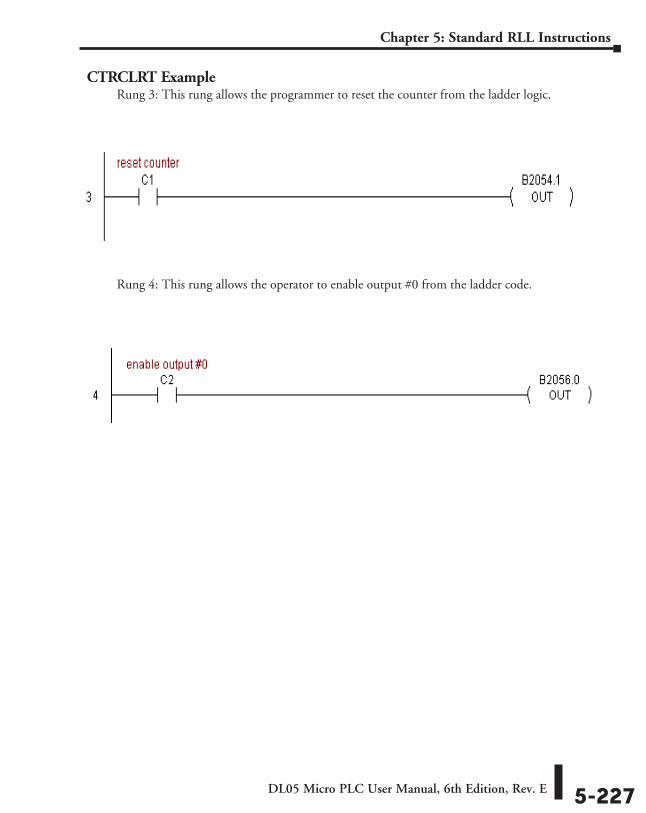
DL05 Micro PLC User Manual, 6th Edition, Rev. E 5-227
Chapter 5: Standard RLL Instructions
CTRCLRT ExampleRung 3: This rung allows the programmer to reset the counter from the ladder logic.
Rung 4: This rung allows the operator to enable output #0 from the ladder code.
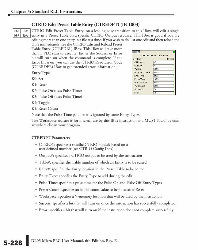
DL05 Micro PLC User Manual, 6th Edition, Rev. E5-228
Chapter 5: Standard RLL Instructions
CTRIO Edit Preset Table Entry (CTREDPT) (IB-1003)CTRIO Edit Preset Table Entry, on a leading edge transition to this IBox, will edit a single entry in a Preset Table on a specific CTRIO Output resource. This IBox is good if you are editing more than one entry in a file at a time. If you wish to do just one edit and then reload the table immediately, see the CTRIO Edit and Reload Preset Table Entry (CTREDRL) IBox. This IBox will take more than 1 PLC scan to execute. Either the Success or Error bit will turn on when the command is complete. If the Error Bit is on, you can use the CTRIO Read Error Code (CTRRDER) IBox to get extended error information.
Entry Type:
K0: Set
K1: Reset
K2: Pulse On (uses Pulse Time)
K3: Pulse Off (uses Pulse Time)
K4: Toggle
K5: Reset Count
Note that the Pulse Time parameter is ignored by some Entry Types.
The Workspace register is for internal use by this IBox instruction and MUST NOT be used anywhere else in your program.
CTREDPT Parameters
• CTRIO#: specifies a specific CTRIO module based on a user defined number (see CTRIO Config Ibox)
• Output#: specifies a CTRIO output to be used by the instruction
• Table#: specifies the Table number of which an Entry is to be edited
• Entry#: specifies the Entry location in the Preset Table to be edited
• Entry Type: specifies the Entry Type to add during the edit
• Pulse Time: specifies a pulse time for the Pulse On and Pulse Off Entry Types
• Preset Count: specifies an initial count value to begin at after Reset
• Workspace: specifies a V-memory location that will be used by the instruction
• Success: specifies a bit that will turn on once the instruction has successfully completed
• Error: specifies a bit that will turn on if the instruction does not complete successfully
DS5 Used
HPP N/A
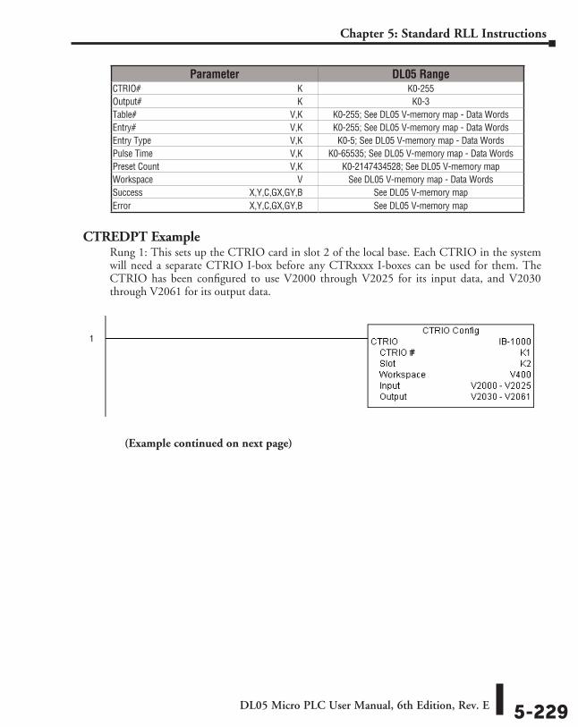
DL05 Micro PLC User Manual, 6th Edition, Rev. E 5-229
Chapter 5: Standard RLL Instructions
CTREDPT ExampleRung 1: This sets up the CTRIO card in slot 2 of the local base. Each CTRIO in the system will need a separate CTRIO I-box before any CTRxxxx I-boxes can be used for them. The CTRIO has been configured to use V2000 through V2025 for its input data, and V2030 through V2061 for its output data.
(Example continued on next page)
Parameter DL05 RangeCTRIO# ⸠⸠⸠⸠⸠⸠⸠⸠⸠⸠⸠⸠⸠⸠⸠⸠⸠⸠⸠⸠⸠⸠⸠⸠⸠⸠⸠⸠⸠⸠⸠⸠⸠⸠⸠⸠⸠⸠⸠⸠⸠⸠⸠⸠⸠⸠⸠⸠⸠⸠⸠⸠⸠⸠⸠⸠⸠⸠⸠⸠⸠⸠⸠⸠⸠⸠⸠⸠ K K0-255Output# ⸠⸠⸠⸠⸠⸠⸠⸠⸠⸠⸠⸠⸠⸠⸠⸠⸠⸠⸠⸠⸠⸠⸠⸠⸠⸠⸠⸠⸠⸠⸠⸠⸠⸠⸠⸠⸠⸠⸠⸠⸠⸠⸠⸠⸠⸠⸠⸠⸠⸠⸠⸠⸠⸠⸠⸠⸠⸠⸠⸠⸠⸠⸠⸠⸠⸠⸠ K K0-3Table# ⸠⸠⸠⸠⸠⸠⸠⸠⸠⸠⸠⸠⸠⸠⸠⸠⸠⸠⸠⸠⸠⸠⸠⸠⸠⸠⸠⸠⸠⸠⸠⸠⸠⸠⸠⸠⸠⸠⸠⸠⸠⸠⸠⸠⸠⸠⸠⸠⸠⸠⸠⸠⸠⸠⸠⸠⸠⸠⸠⸠⸠⸠⸠⸠⸠⸠⸠V,K K0-255; See DL05 V-memory map - Data WordsEntry# ⸠⸠⸠⸠⸠⸠⸠⸠⸠⸠⸠⸠⸠⸠⸠⸠⸠⸠⸠⸠⸠⸠⸠⸠⸠⸠⸠⸠⸠⸠⸠⸠⸠⸠⸠⸠⸠⸠⸠⸠⸠⸠⸠⸠⸠⸠⸠⸠⸠⸠⸠⸠⸠⸠⸠⸠⸠⸠⸠⸠⸠⸠⸠⸠⸠⸠⸠V,K K0-255; See DL05 V-memory map - Data WordsEntry Type ⸠⸠⸠⸠⸠⸠⸠⸠⸠⸠⸠⸠⸠⸠⸠⸠⸠⸠⸠⸠⸠⸠⸠⸠⸠⸠⸠⸠⸠⸠⸠⸠⸠⸠⸠⸠⸠⸠⸠⸠⸠⸠⸠⸠⸠⸠⸠⸠⸠⸠⸠⸠⸠⸠⸠⸠⸠⸠⸠⸠V,K K0-5; See DL05 V-memory map - Data WordsPulse Time ⸠⸠⸠⸠⸠⸠⸠⸠⸠⸠⸠⸠⸠⸠⸠⸠⸠⸠⸠⸠⸠⸠⸠⸠⸠⸠⸠⸠⸠⸠⸠⸠⸠⸠⸠⸠⸠⸠⸠⸠⸠⸠⸠⸠⸠⸠⸠⸠⸠⸠⸠⸠⸠⸠⸠⸠⸠⸠⸠V,K K0-65535; See DL05 V-memory map - Data WordsPreset Count ⸠⸠⸠⸠⸠⸠⸠⸠⸠⸠⸠⸠⸠⸠⸠⸠⸠⸠⸠⸠⸠⸠⸠⸠⸠⸠⸠⸠⸠⸠⸠⸠⸠⸠⸠⸠⸠⸠⸠⸠⸠⸠⸠⸠⸠⸠⸠⸠⸠⸠⸠⸠⸠⸠⸠⸠V,K K0-2147434528; See DL05 V-memory mapWorkspace ⸠⸠⸠⸠⸠⸠⸠⸠⸠⸠⸠⸠⸠⸠⸠⸠⸠⸠⸠⸠⸠⸠⸠⸠⸠⸠⸠⸠⸠⸠⸠⸠⸠⸠⸠⸠⸠⸠⸠⸠⸠⸠⸠⸠⸠⸠⸠⸠⸠⸠⸠⸠⸠⸠⸠⸠⸠⸠⸠⸠⸠⸠ V See DL05 V-memory map - Data WordsSuccess ⸠⸠⸠⸠⸠⸠⸠⸠⸠⸠⸠⸠⸠⸠⸠⸠⸠⸠⸠⸠⸠⸠⸠⸠⸠⸠⸠⸠⸠⸠⸠⸠⸠⸠⸠⸠⸠⸠⸠⸠⸠⸠⸠⸠⸠ X,Y,C,GX,GY,B See DL05 V-memory mapError ⸠⸠⸠⸠⸠⸠⸠⸠⸠⸠⸠⸠⸠⸠⸠⸠⸠⸠⸠⸠⸠⸠⸠⸠⸠⸠⸠⸠⸠⸠⸠⸠⸠⸠⸠⸠⸠⸠⸠⸠⸠⸠⸠⸠⸠⸠⸠⸠⸠⸠ X,Y,C,GX,GY,B See DL05 V-memory map
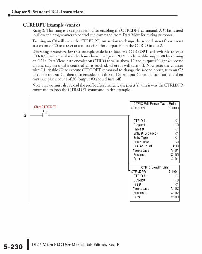
DL05 Micro PLC User Manual, 6th Edition, Rev. E5-230
Chapter 5: Standard RLL Instructions
CTREDPT Example (cont’d)Rung 2: This rung is a sample method for enabling the CTREDPT command. A C-bit is used to allow the programmer to control the command from Data View for testing purposes.
Turning on C0 will cause the CTREDPT instruction to change the second preset from a reset at a count of 20 to a reset at a count of 30 for output #0 on the CTRIO in slot 2.
Operating procedure for this example code is to load the CTREDPT_ex1.cwb file to your CTRIO, then enter the code shown here, change to RUN mode, enable output #0 by turning on C2 in Data View, turn encoder on CTRIO to value above 10 and output #0 light will come on and stay on until a count of 20 is reached, where it will turn off. Now reset the counter with C1, enable C0 to execute CTREDPT command to change the second preset, turn on C2 to enable output #0, then turn encoder to value of 10+ (output #0 should turn on) and then continue past a count of 30 (output #0 should turn off).
Note that we must also reload the profile after changing the preset(s), this is why the CTRLDPR command follows the CTREDPT command in this example.
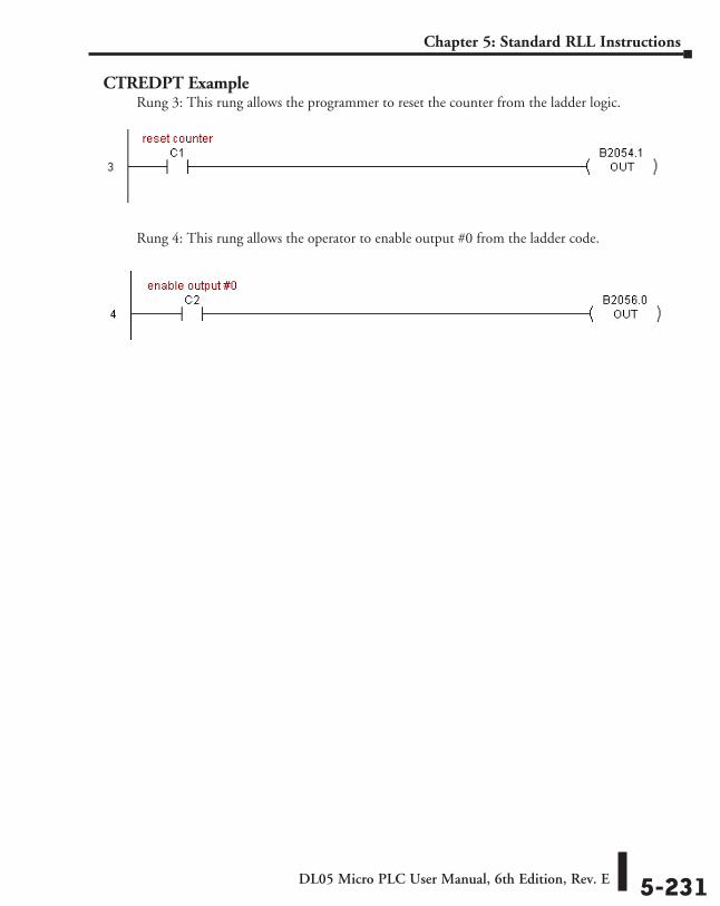
DL05 Micro PLC User Manual, 6th Edition, Rev. E 5-231
Chapter 5: Standard RLL Instructions
CTREDPT ExampleRung 3: This rung allows the programmer to reset the counter from the ladder logic.
Rung 4: This rung allows the operator to enable output #0 from the ladder code.
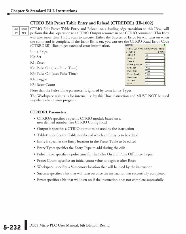
DL05 Micro PLC User Manual, 6th Edition, Rev. E5-232
Chapter 5: Standard RLL Instructions
CTRIO Edit Preset Table Entry and Reload (CTREDRL) (IB-1002)CTRIO Edit Preset Table Entry and Reload, on a leading edge transition to this IBox, will perform this dual operation to a CTRIO Output resource in one CTRIO command. This IBox will take more than 1 PLC scan to execute. Either the Success or Error bit will turn on when the command is complete. If the Error Bit is on, you can use the CTRIO Read Error Code (CTRRDER) IBox to get extended error information.
Entry Type:
K0: Set
K1: Reset
K2: Pulse On (uses Pulse Time)
K3: Pulse Off (uses Pulse Time)
K4: Toggle
K5: Reset Count
Note that the Pulse Time parameter is ignored by some Entry Types.
The Workspace register is for internal use by this IBox instruction and MUST NOT be used anywhere else in your program.
CTREDRL Parameters
• CTRIO#: specifies a specific CTRIO module based on a user defined number (see CTRIO Config Ibox)
• Output#: specifies a CTRIO output to be used by the instruction
• Table#: specifies the Table number of which an Entry is to be edited
• Entry#: specifies the Entry location in the Preset Table to be edited
• Entry Type: specifies the Entry Type to add during the edit
• Pulse Time: specifies a pulse time for the Pulse On and Pulse Off Entry Types
• Preset Count: specifies an initial count value to begin at after Reset
• Workspace: specifies a V-memory location that will be used by the instruction
• Success: specifies a bit that will turn on once the instruction has successfully completed
• Error: specifies a bit that will turn on if the instruction does not complete successfully
DS5 Used
HPP N/A
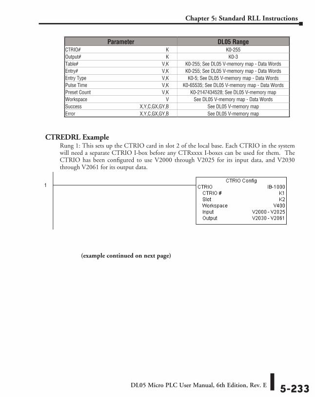
DL05 Micro PLC User Manual, 6th Edition, Rev. E 5-233
Chapter 5: Standard RLL Instructions
CTREDRL ExampleRung 1: This sets up the CTRIO card in slot 2 of the local base. Each CTRIO in the system will need a separate CTRIO I-box before any CTRxxxx I-boxes can be used for them. The CTRIO has been configured to use V2000 through V2025 for its input data, and V2030 through V2061 for its output data.
Parameter DL05 RangeCTRIO# ⸠⸠⸠⸠⸠⸠⸠⸠⸠⸠⸠⸠⸠⸠⸠⸠⸠⸠⸠⸠⸠⸠⸠⸠⸠⸠⸠⸠⸠⸠⸠⸠⸠⸠⸠⸠⸠⸠⸠⸠⸠⸠⸠⸠⸠⸠⸠⸠⸠⸠⸠⸠⸠⸠⸠⸠⸠⸠⸠⸠⸠⸠⸠⸠⸠⸠⸠⸠ K K0-255Output# ⸠⸠⸠⸠⸠⸠⸠⸠⸠⸠⸠⸠⸠⸠⸠⸠⸠⸠⸠⸠⸠⸠⸠⸠⸠⸠⸠⸠⸠⸠⸠⸠⸠⸠⸠⸠⸠⸠⸠⸠⸠⸠⸠⸠⸠⸠⸠⸠⸠⸠⸠⸠⸠⸠⸠⸠⸠⸠⸠⸠⸠⸠⸠⸠⸠⸠⸠ K K0-3Table# ⸠⸠⸠⸠⸠⸠⸠⸠⸠⸠⸠⸠⸠⸠⸠⸠⸠⸠⸠⸠⸠⸠⸠⸠⸠⸠⸠⸠⸠⸠⸠⸠⸠⸠⸠⸠⸠⸠⸠⸠⸠⸠⸠⸠⸠⸠⸠⸠⸠⸠⸠⸠⸠⸠⸠⸠⸠⸠⸠⸠⸠⸠⸠⸠⸠⸠⸠V,K K0-255; See DL05 V-memory map - Data WordsEntry# ⸠⸠⸠⸠⸠⸠⸠⸠⸠⸠⸠⸠⸠⸠⸠⸠⸠⸠⸠⸠⸠⸠⸠⸠⸠⸠⸠⸠⸠⸠⸠⸠⸠⸠⸠⸠⸠⸠⸠⸠⸠⸠⸠⸠⸠⸠⸠⸠⸠⸠⸠⸠⸠⸠⸠⸠⸠⸠⸠⸠⸠⸠⸠⸠⸠⸠⸠V,K K0-255; See DL05 V-memory map - Data WordsEntry Type ⸠⸠⸠⸠⸠⸠⸠⸠⸠⸠⸠⸠⸠⸠⸠⸠⸠⸠⸠⸠⸠⸠⸠⸠⸠⸠⸠⸠⸠⸠⸠⸠⸠⸠⸠⸠⸠⸠⸠⸠⸠⸠⸠⸠⸠⸠⸠⸠⸠⸠⸠⸠⸠⸠⸠⸠⸠⸠⸠⸠V,K K0-5; See DL05 V-memory map - Data WordsPulse Time ⸠⸠⸠⸠⸠⸠⸠⸠⸠⸠⸠⸠⸠⸠⸠⸠⸠⸠⸠⸠⸠⸠⸠⸠⸠⸠⸠⸠⸠⸠⸠⸠⸠⸠⸠⸠⸠⸠⸠⸠⸠⸠⸠⸠⸠⸠⸠⸠⸠⸠⸠⸠⸠⸠⸠⸠⸠⸠⸠V,K K0-65535; See DL05 V-memory map - Data WordsPreset Count ⸠⸠⸠⸠⸠⸠⸠⸠⸠⸠⸠⸠⸠⸠⸠⸠⸠⸠⸠⸠⸠⸠⸠⸠⸠⸠⸠⸠⸠⸠⸠⸠⸠⸠⸠⸠⸠⸠⸠⸠⸠⸠⸠⸠⸠⸠⸠⸠⸠⸠⸠⸠⸠⸠⸠⸠V,K K0-2147434528; See DL05 V-memory mapWorkspace ⸠⸠⸠⸠⸠⸠⸠⸠⸠⸠⸠⸠⸠⸠⸠⸠⸠⸠⸠⸠⸠⸠⸠⸠⸠⸠⸠⸠⸠⸠⸠⸠⸠⸠⸠⸠⸠⸠⸠⸠⸠⸠⸠⸠⸠⸠⸠⸠⸠⸠⸠⸠⸠⸠⸠⸠⸠⸠⸠⸠⸠⸠ V See DL05 V-memory map - Data WordsSuccess ⸠⸠⸠⸠⸠⸠⸠⸠⸠⸠⸠⸠⸠⸠⸠⸠⸠⸠⸠⸠⸠⸠⸠⸠⸠⸠⸠⸠⸠⸠⸠⸠⸠⸠⸠⸠⸠⸠⸠⸠⸠⸠⸠⸠⸠ X,Y,C,GX,GY,B See DL05 V-memory mapError ⸠⸠⸠⸠⸠⸠⸠⸠⸠⸠⸠⸠⸠⸠⸠⸠⸠⸠⸠⸠⸠⸠⸠⸠⸠⸠⸠⸠⸠⸠⸠⸠⸠⸠⸠⸠⸠⸠⸠⸠⸠⸠⸠⸠⸠⸠⸠⸠⸠⸠ X,Y,C,GX,GY,B See DL05 V-memory map
(example continued on next page)
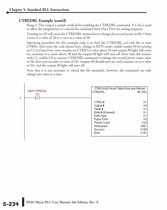
DL05 Micro PLC User Manual, 6th Edition, Rev. E5-234
Chapter 5: Standard RLL Instructions
CTREDRL Example (cont’d)Rung 2: This rung is a sample method for enabling the CTREDRL command. A C-bit is used to allow the programmer to control the command from Data View for testing purposes.
Turning on C0 will cause the CTREDRL instruction to change the second preset in file 1 from a reset at a value of 20 to a reset at a value of 30.
Operating procedure for this example code is to load the CTREDRL_ex1.cwb file to your CTRIO, then enter the code shown here, change to RUN mode, enable output #0 by turning on C2 in Data View, turn encoder on CTRIO to value above 10 and output #0 light will come on, continue to a count above 20 and the output #0 light will turn off. Now reset the counter with C1, enable C0 to execute CTREDRL command to change the second preset count value to 30, then turn encoder to value of 10+ (output #0 should turn on) and continue on to a value of 30+ and the output #0 light will turn off.
Note that it is not necessary to reload this file separately, however, the command can only change one value at a time.
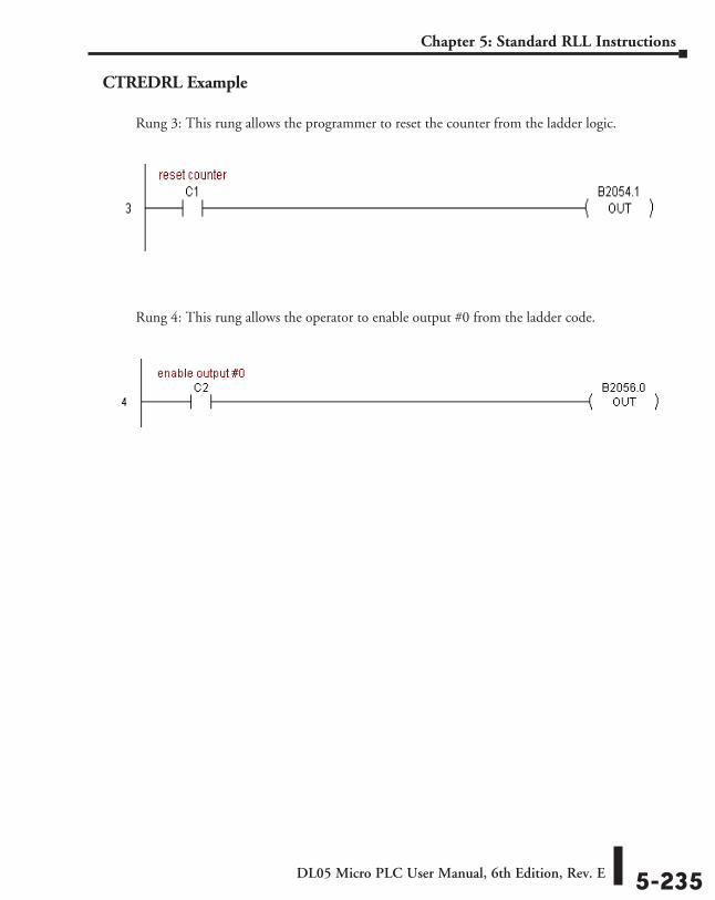
DL05 Micro PLC User Manual, 6th Edition, Rev. E 5-235
Chapter 5: Standard RLL Instructions
CTREDRL Example
Rung 3: This rung allows the programmer to reset the counter from the ladder logic.
Rung 4: This rung allows the operator to enable output #0 from the ladder code.
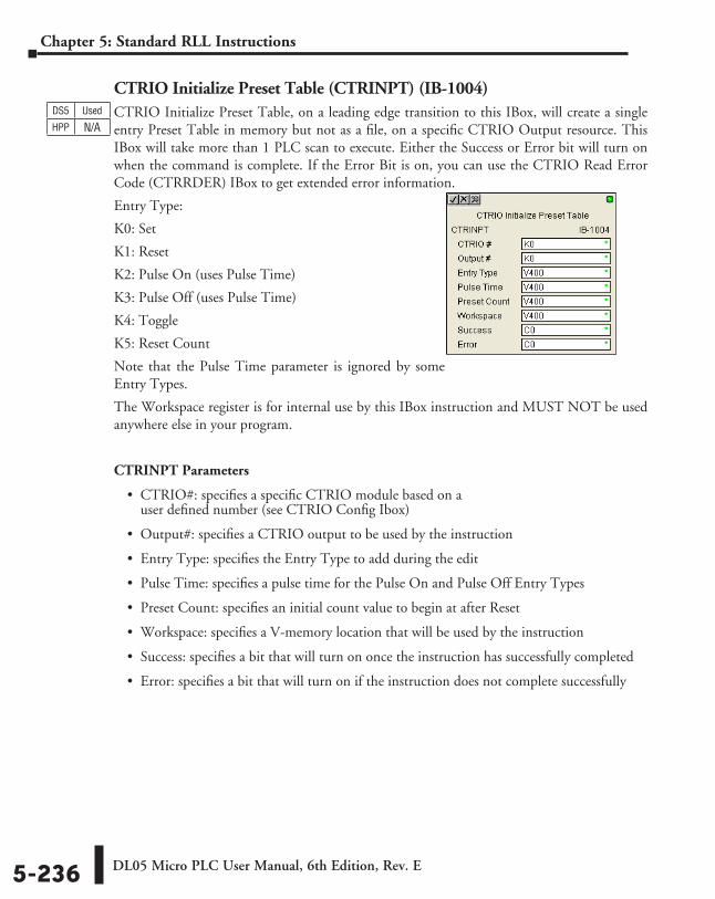
DL05 Micro PLC User Manual, 6th Edition, Rev. E5-236
Chapter 5: Standard RLL Instructions
CTRIO Initialize Preset Table (CTRINPT) (IB-1004)CTRIO Initialize Preset Table, on a leading edge transition to this IBox, will create a single entry Preset Table in memory but not as a file, on a specific CTRIO Output resource. This IBox will take more than 1 PLC scan to execute. Either the Success or Error bit will turn on when the command is complete. If the Error Bit is on, you can use the CTRIO Read Error Code (CTRRDER) IBox to get extended error information.
Entry Type:
K0: Set
K1: Reset
K2: Pulse On (uses Pulse Time)
K3: Pulse Off (uses Pulse Time)
K4: Toggle
K5: Reset Count
Note that the Pulse Time parameter is ignored by some Entry Types.
The Workspace register is for internal use by this IBox instruction and MUST NOT be used anywhere else in your program.
CTRINPT Parameters
• CTRIO#: specifies a specific CTRIO module based on a user defined number (see CTRIO Config Ibox)
• Output#: specifies a CTRIO output to be used by the instruction
• Entry Type: specifies the Entry Type to add during the edit
• Pulse Time: specifies a pulse time for the Pulse On and Pulse Off Entry Types
• Preset Count: specifies an initial count value to begin at after Reset
• Workspace: specifies a V-memory location that will be used by the instruction
• Success: specifies a bit that will turn on once the instruction has successfully completed
• Error: specifies a bit that will turn on if the instruction does not complete successfully
DS5 Used
HPP N/A
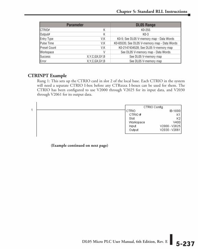
DL05 Micro PLC User Manual, 6th Edition, Rev. E 5-237
Chapter 5: Standard RLL Instructions
CTRINPT ExampleRung 1: This sets up the CTRIO card in slot 2 of the local base. Each CTRIO in the system will need a separate CTRIO I-box before any CTRxxxx I-boxes can be used for them. The CTRIO has been configured to use V2000 through V2025 for its input data, and V2030 through V2061 for its output data.
Parameter DL05 RangeCTRIO# ⸠⸠⸠⸠⸠⸠⸠⸠⸠⸠⸠⸠⸠⸠⸠⸠⸠⸠⸠⸠⸠⸠⸠⸠⸠⸠⸠⸠⸠⸠⸠⸠⸠⸠⸠⸠⸠⸠⸠⸠⸠⸠⸠⸠⸠⸠⸠⸠⸠⸠⸠⸠⸠⸠⸠⸠⸠⸠⸠⸠⸠⸠⸠⸠⸠⸠⸠⸠ K K0-255Output# ⸠⸠⸠⸠⸠⸠⸠⸠⸠⸠⸠⸠⸠⸠⸠⸠⸠⸠⸠⸠⸠⸠⸠⸠⸠⸠⸠⸠⸠⸠⸠⸠⸠⸠⸠⸠⸠⸠⸠⸠⸠⸠⸠⸠⸠⸠⸠⸠⸠⸠⸠⸠⸠⸠⸠⸠⸠⸠⸠⸠⸠⸠⸠⸠⸠⸠⸠ K K0-3Entry Type ⸠⸠⸠⸠⸠⸠⸠⸠⸠⸠⸠⸠⸠⸠⸠⸠⸠⸠⸠⸠⸠⸠⸠⸠⸠⸠⸠⸠⸠⸠⸠⸠⸠⸠⸠⸠⸠⸠⸠⸠⸠⸠⸠⸠⸠⸠⸠⸠⸠⸠⸠⸠⸠⸠⸠⸠⸠⸠⸠⸠V,K K0-5; See DL05 V-memory map - Data WordsPulse Time ⸠⸠⸠⸠⸠⸠⸠⸠⸠⸠⸠⸠⸠⸠⸠⸠⸠⸠⸠⸠⸠⸠⸠⸠⸠⸠⸠⸠⸠⸠⸠⸠⸠⸠⸠⸠⸠⸠⸠⸠⸠⸠⸠⸠⸠⸠⸠⸠⸠⸠⸠⸠⸠⸠⸠⸠⸠⸠⸠V,K K0-65535; See DL05 V-memory map - Data WordsPreset Count ⸠⸠⸠⸠⸠⸠⸠⸠⸠⸠⸠⸠⸠⸠⸠⸠⸠⸠⸠⸠⸠⸠⸠⸠⸠⸠⸠⸠⸠⸠⸠⸠⸠⸠⸠⸠⸠⸠⸠⸠⸠⸠⸠⸠⸠⸠⸠⸠⸠⸠⸠⸠⸠⸠⸠⸠V,K K0-2147434528; See DL05 V-memory mapWorkspace ⸠⸠⸠⸠⸠⸠⸠⸠⸠⸠⸠⸠⸠⸠⸠⸠⸠⸠⸠⸠⸠⸠⸠⸠⸠⸠⸠⸠⸠⸠⸠⸠⸠⸠⸠⸠⸠⸠⸠⸠⸠⸠⸠⸠⸠⸠⸠⸠⸠⸠⸠⸠⸠⸠⸠⸠⸠⸠⸠⸠⸠⸠ V See DL05 V-memory map - Data WordsSuccess ⸠⸠⸠⸠⸠⸠⸠⸠⸠⸠⸠⸠⸠⸠⸠⸠⸠⸠⸠⸠⸠⸠⸠⸠⸠⸠⸠⸠⸠⸠⸠⸠⸠⸠⸠⸠⸠⸠⸠⸠⸠⸠⸠⸠⸠ X,Y,C,GX,GY,B See DL05 V-memory mapError ⸠⸠⸠⸠⸠⸠⸠⸠⸠⸠⸠⸠⸠⸠⸠⸠⸠⸠⸠⸠⸠⸠⸠⸠⸠⸠⸠⸠⸠⸠⸠⸠⸠⸠⸠⸠⸠⸠⸠⸠⸠⸠⸠⸠⸠⸠⸠⸠⸠⸠ X,Y,C,GX,GY,B See DL05 V-memory map
(Example continued on next page)
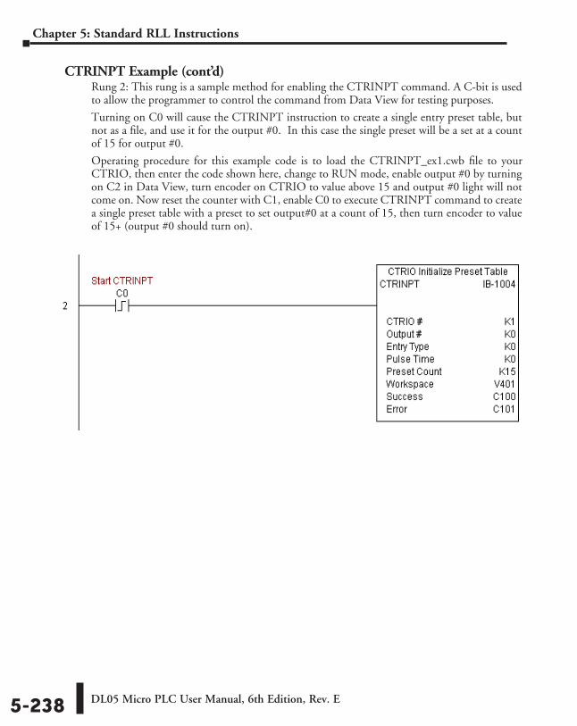
DL05 Micro PLC User Manual, 6th Edition, Rev. E5-238
Chapter 5: Standard RLL Instructions
CTRINPT Example (cont’d)Rung 2: This rung is a sample method for enabling the CTRINPT command. A C-bit is used to allow the programmer to control the command from Data View for testing purposes.
Turning on C0 will cause the CTRINPT instruction to create a single entry preset table, but not as a file, and use it for the output #0. In this case the single preset will be a set at a count of 15 for output #0.
Operating procedure for this example code is to load the CTRINPT_ex1.cwb file to your CTRIO, then enter the code shown here, change to RUN mode, enable output #0 by turning on C2 in Data View, turn encoder on CTRIO to value above 15 and output #0 light will not come on. Now reset the counter with C1, enable C0 to execute CTRINPT command to create a single preset table with a preset to set output#0 at a count of 15, then turn encoder to value of 15+ (output #0 should turn on).
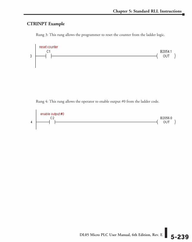
DL05 Micro PLC User Manual, 6th Edition, Rev. E 5-239
Chapter 5: Standard RLL Instructions
CTRINPT Example
Rung 3: This rung allows the programmer to reset the counter from the ladder logic.
Rung 4: This rung allows the operator to enable output #0 from the ladder code.
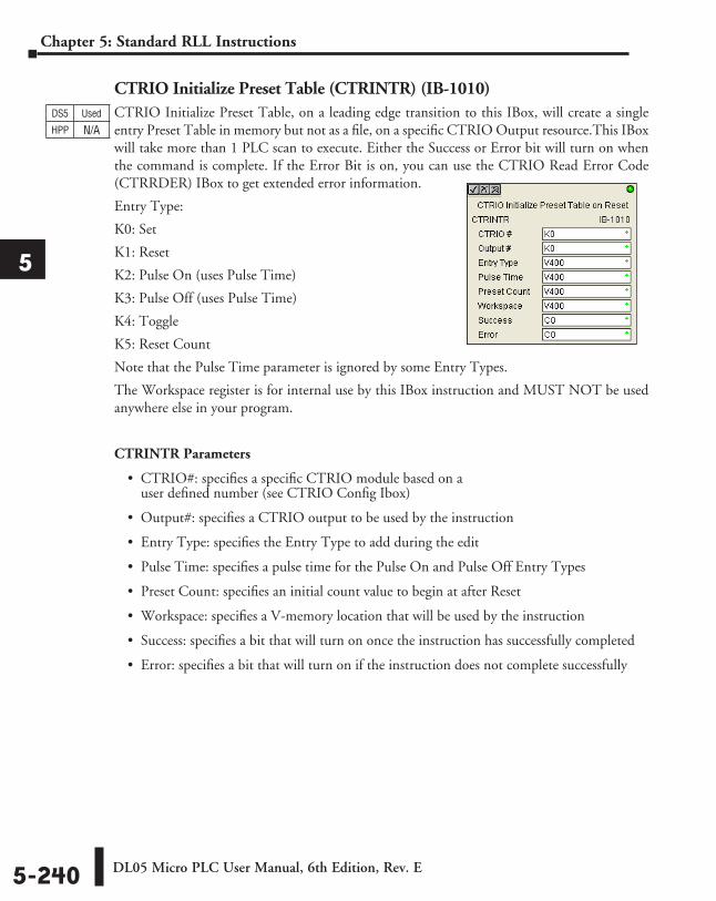
DL05 Micro PLC User Manual, 6th Edition, Rev. E5-240
Chapter 5: Standard RLL Instructions
1
2
3
4
5
6
7
8
9
10
11
12
13
14
A
B
C
D
CTRIO Initialize Preset Table (CTRINTR) (IB-1010)CTRIO Initialize Preset Table, on a leading edge transition to this IBox, will create a single entry Preset Table in memory but not as a file, on a specific CTRIO Output resource.This IBox will take more than 1 PLC scan to execute. Either the Success or Error bit will turn on when the command is complete. If the Error Bit is on, you can use the CTRIO Read Error Code (CTRRDER) IBox to get extended error information.
Entry Type:
K0: Set
K1: Reset
K2: Pulse On (uses Pulse Time)
K3: Pulse Off (uses Pulse Time)
K4: Toggle
K5: Reset Count
Note that the Pulse Time parameter is ignored by some Entry Types.
The Workspace register is for internal use by this IBox instruction and MUST NOT be used anywhere else in your program.
CTRINTR Parameters
• CTRIO#: specifies a specific CTRIO module based on a user defined number (see CTRIO Config Ibox)
• Output#: specifies a CTRIO output to be used by the instruction
• Entry Type: specifies the Entry Type to add during the edit
• Pulse Time: specifies a pulse time for the Pulse On and Pulse Off Entry Types
• Preset Count: specifies an initial count value to begin at after Reset
• Workspace: specifies a V-memory location that will be used by the instruction
• Success: specifies a bit that will turn on once the instruction has successfully completed
• Error: specifies a bit that will turn on if the instruction does not complete successfully
DS5 Used
HPP N/A
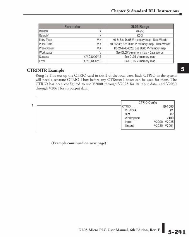
DL05 Micro PLC User Manual, 6th Edition, Rev. E 5-241
Chapter 5: Standard RLL Instructions
1
2
3
4
5
6
7
8
9
10
11
12
13
14
A
B
C
D
CTRINTR ExampleRung 1: This sets up the CTRIO card in slot 2 of the local base. Each CTRIO in the system will need a separate CTRIO I-box before any CTRxxxx I-boxes can be used for them. The CTRIO has been configured to use V2000 through V2025 for its input data, and V2030 through V2061 for its output data.
Parameter DL05 RangeCTRIO# ⸠⸠⸠⸠⸠⸠⸠⸠⸠⸠⸠⸠⸠⸠⸠⸠⸠⸠⸠⸠⸠⸠⸠⸠⸠⸠⸠⸠⸠⸠⸠⸠⸠⸠⸠⸠⸠⸠⸠⸠⸠⸠⸠⸠⸠⸠⸠⸠⸠⸠⸠⸠⸠⸠⸠⸠⸠⸠⸠⸠⸠⸠⸠⸠⸠⸠⸠⸠ K K0-255Output# ⸠⸠⸠⸠⸠⸠⸠⸠⸠⸠⸠⸠⸠⸠⸠⸠⸠⸠⸠⸠⸠⸠⸠⸠⸠⸠⸠⸠⸠⸠⸠⸠⸠⸠⸠⸠⸠⸠⸠⸠⸠⸠⸠⸠⸠⸠⸠⸠⸠⸠⸠⸠⸠⸠⸠⸠⸠⸠⸠⸠⸠⸠⸠⸠⸠⸠⸠ K K0-3Entry Type ⸠⸠⸠⸠⸠⸠⸠⸠⸠⸠⸠⸠⸠⸠⸠⸠⸠⸠⸠⸠⸠⸠⸠⸠⸠⸠⸠⸠⸠⸠⸠⸠⸠⸠⸠⸠⸠⸠⸠⸠⸠⸠⸠⸠⸠⸠⸠⸠⸠⸠⸠⸠⸠⸠⸠⸠⸠⸠⸠⸠V,K K0-5; See DL05 V-memory map - Data WordsPulse Time ⸠⸠⸠⸠⸠⸠⸠⸠⸠⸠⸠⸠⸠⸠⸠⸠⸠⸠⸠⸠⸠⸠⸠⸠⸠⸠⸠⸠⸠⸠⸠⸠⸠⸠⸠⸠⸠⸠⸠⸠⸠⸠⸠⸠⸠⸠⸠⸠⸠⸠⸠⸠⸠⸠⸠⸠⸠⸠⸠V,K K0-65535; See DL05 V-memory map - Data WordsPreset Count ⸠⸠⸠⸠⸠⸠⸠⸠⸠⸠⸠⸠⸠⸠⸠⸠⸠⸠⸠⸠⸠⸠⸠⸠⸠⸠⸠⸠⸠⸠⸠⸠⸠⸠⸠⸠⸠⸠⸠⸠⸠⸠⸠⸠⸠⸠⸠⸠⸠⸠⸠⸠⸠⸠⸠⸠V,K K0-2147434528; See DL05 V-memory mapWorkspace ⸠⸠⸠⸠⸠⸠⸠⸠⸠⸠⸠⸠⸠⸠⸠⸠⸠⸠⸠⸠⸠⸠⸠⸠⸠⸠⸠⸠⸠⸠⸠⸠⸠⸠⸠⸠⸠⸠⸠⸠⸠⸠⸠⸠⸠⸠⸠⸠⸠⸠⸠⸠⸠⸠⸠⸠⸠⸠⸠⸠⸠⸠ V See DL05 V-memory map - Data WordsSuccess ⸠⸠⸠⸠⸠⸠⸠⸠⸠⸠⸠⸠⸠⸠⸠⸠⸠⸠⸠⸠⸠⸠⸠⸠⸠⸠⸠⸠⸠⸠⸠⸠⸠⸠⸠⸠⸠⸠⸠⸠⸠⸠⸠⸠⸠ X,Y,C,GX,GY,B See DL05 V-memory mapError ⸠⸠⸠⸠⸠⸠⸠⸠⸠⸠⸠⸠⸠⸠⸠⸠⸠⸠⸠⸠⸠⸠⸠⸠⸠⸠⸠⸠⸠⸠⸠⸠⸠⸠⸠⸠⸠⸠⸠⸠⸠⸠⸠⸠⸠⸠⸠⸠⸠⸠ X,Y,C,GX,GY,B See DL05 V-memory map
(Example continued on next page)
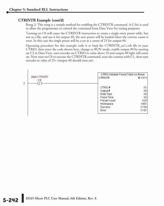
DL05 Micro PLC User Manual, 6th Edition, Rev. E5-242
Chapter 5: Standard RLL Instructions
CTRINTR Example (cont’d)Rung 2: This rung is a sample method for enabling the CTRINTR command. A C-bit is used to allow the programmer to control the command from Data View for testing purposes.
Turning on C0 will cause the CTRINTR instruction to create a single entry preset table, but not as a file, and use it for output #0, the new preset will be loaded when the current count is reset. In this case the single preset will be a set at a count of 25 for output #0.
Operating procedure for this example code is to load the CTRINTR_ex1.cwb file to your CTRIO, then enter the code shown here, change to RUN mode, enable output #0 by turning on C2 in Data View, turn encoder on CTRIO to value above 10 and output #0 light will come on. Now turn on C0 to execute the CTRINTR command, reset the counter with C1, then turn encoder to value of 25+ (output #0 should turn on).
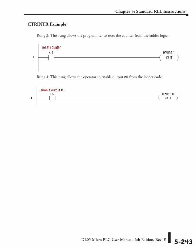
DL05 Micro PLC User Manual, 6th Edition, Rev. E 5-243
Chapter 5: Standard RLL Instructions
CTRINTR Example
Rung 3: This rung allows the programmer to reset the counter from the ladder logic.
Rung 4: This rung allows the operator to enable output #0 from the ladder code.
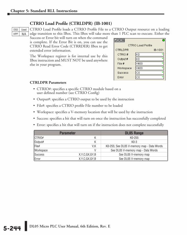
DL05 Micro PLC User Manual, 6th Edition, Rev. E5-244
Chapter 5: Standard RLL Instructions
CTRIO Load Profile (CTRLDPR) (IB-1001)CTRIO Load Profile loads a CTRIO Profile File to a CTRIO Output resource on a leading edge transition to this IBox. This IBox will take more than 1 PLC scan to execute. Either the Success or Error bit will turn on when the command is complete. If the Error Bit is on, you can use the CTRIO Read Error Code (CTRRDER) IBox to get extended error information.
The Workspace register is for internal use by this IBox instruction and MUST NOT be used anywhere else in your program.
CTRLDPR Parameters
• CTRIO#: specifies a specific CTRIO module based on a user defined number (see CTRIO Config)
• Output#: specifies a CTRIO output to be used by the instruction
• File#: specifies a CTRIO profile File number to be loaded
• Workspace: specifies a V-memory location that will be used by the instruction
• Success: specifies a bit that will turn on once the instruction has successfully completed
• Error: specifies a bit that will turn on if the instruction does not complete successfully
DS5 Used
HPP N/A
Parameter DL05 RangeCTRIO# ⸠⸠⸠⸠⸠⸠⸠⸠⸠⸠⸠⸠⸠⸠⸠⸠⸠⸠⸠⸠⸠⸠⸠⸠⸠⸠⸠⸠⸠⸠⸠⸠⸠⸠⸠⸠⸠⸠⸠⸠⸠⸠⸠⸠⸠⸠⸠⸠⸠⸠⸠⸠⸠⸠⸠⸠⸠⸠⸠⸠⸠⸠⸠⸠⸠⸠⸠⸠ K K0-255Output# ⸠⸠⸠⸠⸠⸠⸠⸠⸠⸠⸠⸠⸠⸠⸠⸠⸠⸠⸠⸠⸠⸠⸠⸠⸠⸠⸠⸠⸠⸠⸠⸠⸠⸠⸠⸠⸠⸠⸠⸠⸠⸠⸠⸠⸠⸠⸠⸠⸠⸠⸠⸠⸠⸠⸠⸠⸠⸠⸠⸠⸠⸠⸠⸠⸠⸠⸠ K K0-3File# ⸠⸠⸠⸠⸠⸠⸠⸠⸠⸠⸠⸠⸠⸠⸠⸠⸠⸠⸠⸠⸠⸠⸠⸠⸠⸠⸠⸠⸠⸠⸠⸠⸠⸠⸠⸠⸠⸠⸠⸠⸠⸠⸠⸠⸠⸠⸠⸠⸠⸠⸠⸠⸠⸠⸠⸠⸠⸠⸠⸠⸠⸠⸠⸠⸠⸠⸠⸠⸠⸠V,K K0-255; See DL05 V-memory map - Data WordsWorkspace ⸠⸠⸠⸠⸠⸠⸠⸠⸠⸠⸠⸠⸠⸠⸠⸠⸠⸠⸠⸠⸠⸠⸠⸠⸠⸠⸠⸠⸠⸠⸠⸠⸠⸠⸠⸠⸠⸠⸠⸠⸠⸠⸠⸠⸠⸠⸠⸠⸠⸠⸠⸠⸠⸠⸠⸠⸠⸠⸠⸠⸠⸠ V See DL05 V-memory map - Data WordsSuccess ⸠⸠⸠⸠⸠⸠⸠⸠⸠⸠⸠⸠⸠⸠⸠⸠⸠⸠⸠⸠⸠⸠⸠⸠⸠⸠⸠⸠⸠⸠⸠⸠⸠⸠⸠⸠⸠⸠⸠⸠⸠⸠⸠⸠⸠ X,Y,C,GX,GY,B See DL05 V-memory mapError ⸠⸠⸠⸠⸠⸠⸠⸠⸠⸠⸠⸠⸠⸠⸠⸠⸠⸠⸠⸠⸠⸠⸠⸠⸠⸠⸠⸠⸠⸠⸠⸠⸠⸠⸠⸠⸠⸠⸠⸠⸠⸠⸠⸠⸠⸠⸠⸠⸠⸠ X,Y,C,GX,GY,B See DL05 V-memory map
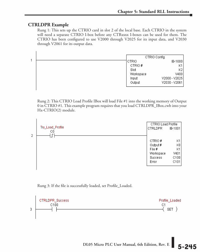
DL05 Micro PLC User Manual, 6th Edition, Rev. E 5-245
Chapter 5: Standard RLL Instructions
CTRLDPR ExampleRung 1: This sets up the CTRIO card in slot 2 of the local base. Each CTRIO in the system will need a separate CTRIO I-box before any CTRxxxx I-boxes can be used for them. The CTRIO has been configured to use V2000 through V2025 for its input data, and V2030 through V2061 for its output data.
Rung 2: This CTRIO Load Profile IBox will load File #1 into the working memory of Output 0 in CTRIO #1. This example program requires that you load CTRLDPR_IBox.cwb into your Hx-CTRIO(2) module.
Rung 3: If the file is successfully loaded, set Profile_Loaded.
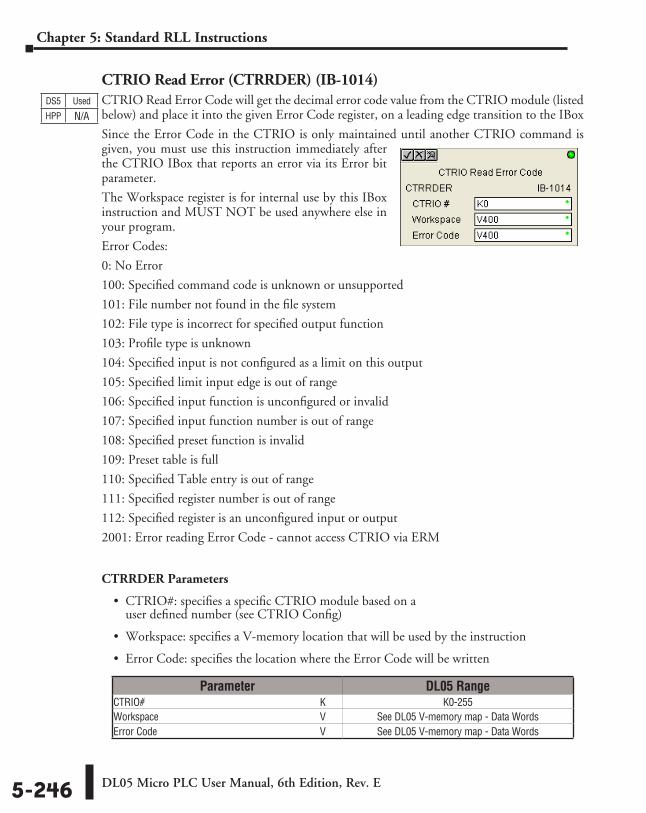
DL05 Micro PLC User Manual, 6th Edition, Rev. E5-246
Chapter 5: Standard RLL Instructions
CTRIO Read Error (CTRRDER) (IB-1014)CTRIO Read Error Code will get the decimal error code value from the CTRIO module (listed below) and place it into the given Error Code register, on a leading edge transition to the IBox
Since the Error Code in the CTRIO is only maintained until another CTRIO command is given, you must use this instruction immediately after the CTRIO IBox that reports an error via its Error bit parameter.
The Workspace register is for internal use by this IBox instruction and MUST NOT be used anywhere else in your program.
Error Codes:
0: No Error
100: Specified command code is unknown or unsupported
101: File number not found in the file system
102: File type is incorrect for specified output function
103: Profile type is unknown
104: Specified input is not configured as a limit on this output
105: Specified limit input edge is out of range
106: Specified input function is unconfigured or invalid
107: Specified input function number is out of range
108: Specified preset function is invalid
109: Preset table is full
110: Specified Table entry is out of range
111: Specified register number is out of range
112: Specified register is an unconfigured input or output
2001: Error reading Error Code - cannot access CTRIO via ERM
CTRRDER Parameters
• CTRIO#: specifies a specific CTRIO module based on a user defined number (see CTRIO Config)
• Workspace: specifies a V-memory location that will be used by the instruction
• Error Code: specifies the location where the Error Code will be written
DS5 Used
HPP N/A
Parameter DL05 RangeCTRIO# ⸠⸠⸠⸠⸠⸠⸠⸠⸠⸠⸠⸠⸠⸠⸠⸠⸠⸠⸠⸠⸠⸠⸠⸠⸠⸠⸠⸠⸠⸠⸠⸠⸠⸠⸠⸠⸠⸠⸠⸠⸠⸠⸠⸠⸠⸠⸠⸠⸠⸠⸠⸠⸠⸠⸠⸠⸠⸠⸠⸠⸠⸠⸠⸠⸠⸠⸠⸠ K K0-255Workspace ⸠⸠⸠⸠⸠⸠⸠⸠⸠⸠⸠⸠⸠⸠⸠⸠⸠⸠⸠⸠⸠⸠⸠⸠⸠⸠⸠⸠⸠⸠⸠⸠⸠⸠⸠⸠⸠⸠⸠⸠⸠⸠⸠⸠⸠⸠⸠⸠⸠⸠⸠⸠⸠⸠⸠⸠⸠⸠⸠⸠⸠⸠ V See DL05 V-memory map - Data WordsError Code ⸠⸠⸠⸠⸠⸠⸠⸠⸠⸠⸠⸠⸠⸠⸠⸠⸠⸠⸠⸠⸠⸠⸠⸠⸠⸠⸠⸠⸠⸠⸠⸠⸠⸠⸠⸠⸠⸠⸠⸠⸠⸠⸠⸠⸠⸠⸠⸠⸠⸠⸠⸠⸠⸠⸠⸠⸠⸠⸠⸠⸠⸠⸠ V See DL05 V-memory map - Data Words
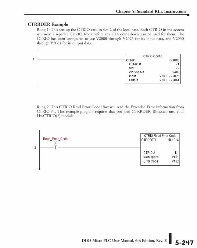
DL05 Micro PLC User Manual, 6th Edition, Rev. E 5-247
Chapter 5: Standard RLL Instructions
CTRRDER ExampleRung 1: This sets up the CTRIO card in slot 2 of the local base. Each CTRIO in the system will need a separate CTRIO I-box before any CTRxxxx I-boxes can be used for them. The CTRIO has been configured to use V2000 through V2025 for its input data, and V2030 through V2061 for its output data.
Rung 2: This CTRIO Read Error Code IBox will read the Extended Error information from CTRIO #1. This example program requires that you load CTRRDER_IBox.cwb into your Hx-CTRIO(2) module.
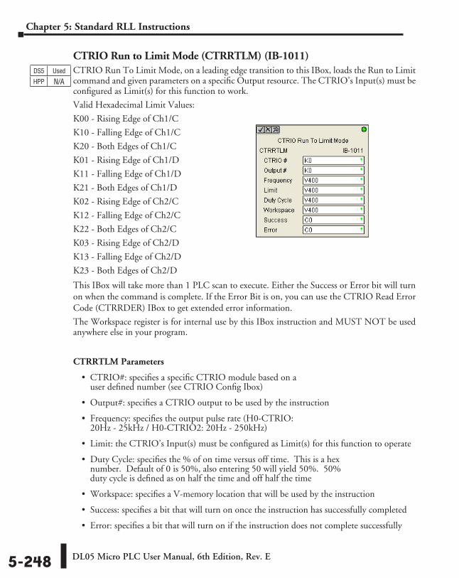
DL05 Micro PLC User Manual, 6th Edition, Rev. E5-248
Chapter 5: Standard RLL Instructions
CTRIO Run to Limit Mode (CTRRTLM) (IB-1011)CTRIO Run To Limit Mode, on a leading edge transition to this IBox, loads the Run to Limit command and given parameters on a specific Output resource. The CTRIO’s Input(s) must be configured as Limit(s) for this function to work.
Valid Hexadecimal Limit Values:
K00 - Rising Edge of Ch1/C
K10 - Falling Edge of Ch1/C
K20 - Both Edges of Ch1/C
K01 - Rising Edge of Ch1/D
K11 - Falling Edge of Ch1/D
K21 - Both Edges of Ch1/D
K02 - Rising Edge of Ch2/C
K12 - Falling Edge of Ch2/C
K22 - Both Edges of Ch2/C
K03 - Rising Edge of Ch2/D
K13 - Falling Edge of Ch2/D
K23 - Both Edges of Ch2/D
This IBox will take more than 1 PLC scan to execute. Either the Success or Error bit will turn on when the command is complete. If the Error Bit is on, you can use the CTRIO Read Error Code (CTRRDER) IBox to get extended error information.
The Workspace register is for internal use by this IBox instruction and MUST NOT be used anywhere else in your program.
CTRRTLM Parameters
• CTRIO#: specifies a specific CTRIO module based on a user defined number (see CTRIO Config Ibox)
• Output#: specifies a CTRIO output to be used by the instruction
• Frequency: specifies the output pulse rate (H0-CTRIO: 20Hz - 25kHz / H0-CTRIO2: 20Hz - 250kHz)
• Limit: the CTRIO’s Input(s) must be configured as Limit(s) for this function to operate
• Duty Cycle: specifies the % of on time versus off time. This is a hex number. Default of 0 is 50%, also entering 50 will yield 50%. 50% duty cycle is defined as on half the time and off half the time
• Workspace: specifies a V-memory location that will be used by the instruction
• Success: specifies a bit that will turn on once the instruction has successfully completed
• Error: specifies a bit that will turn on if the instruction does not complete successfully
DS5 Used
HPP N/A
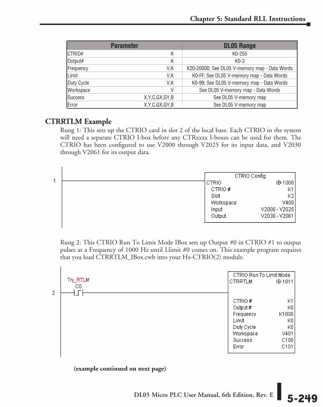
DL05 Micro PLC User Manual, 6th Edition, Rev. E 5-249
Chapter 5: Standard RLL Instructions
CTRRTLM ExampleRung 1: This sets up the CTRIO card in slot 2 of the local base. Each CTRIO in the system will need a separate CTRIO I-box before any CTRxxxx I-boxes can be used for them. The CTRIO has been configured to use V2000 through V2025 for its input data, and V2030 through V2061 for its output data.
Rung 2: This CTRIO Run To Limit Mode IBox sets up Output #0 in CTRIO #1 to output pulses at a Frequency of 1000 Hz until Llimit #0 comes on. This example program requires that you load CTRRTLM_IBox.cwb into your Hx-CTRIO(2) module.
Parameter DL05 RangeCTRIO# ⸠⸠⸠⸠⸠⸠⸠⸠⸠⸠⸠⸠⸠⸠⸠⸠⸠⸠⸠⸠⸠⸠⸠⸠⸠⸠⸠⸠⸠⸠⸠⸠⸠⸠⸠⸠⸠⸠⸠⸠⸠⸠⸠⸠⸠⸠⸠⸠⸠⸠⸠⸠⸠⸠⸠⸠⸠⸠⸠⸠⸠⸠⸠⸠⸠⸠⸠⸠ K K0-255Output# ⸠⸠⸠⸠⸠⸠⸠⸠⸠⸠⸠⸠⸠⸠⸠⸠⸠⸠⸠⸠⸠⸠⸠⸠⸠⸠⸠⸠⸠⸠⸠⸠⸠⸠⸠⸠⸠⸠⸠⸠⸠⸠⸠⸠⸠⸠⸠⸠⸠⸠⸠⸠⸠⸠⸠⸠⸠⸠⸠⸠⸠⸠⸠⸠⸠⸠⸠ K K0-3Frequency ⸠⸠⸠⸠⸠⸠⸠⸠⸠⸠⸠⸠⸠⸠⸠⸠⸠⸠⸠⸠⸠⸠⸠⸠⸠⸠⸠⸠⸠⸠⸠⸠⸠⸠⸠⸠⸠⸠⸠⸠⸠⸠⸠⸠⸠⸠⸠⸠⸠⸠⸠⸠⸠⸠⸠⸠⸠⸠⸠⸠⸠V,K K20-20000; See DL05 V-memory map - Data WordsLimit ⸠⸠⸠⸠⸠⸠⸠⸠⸠⸠⸠⸠⸠⸠⸠⸠⸠⸠⸠⸠⸠⸠⸠⸠⸠⸠⸠⸠⸠⸠⸠⸠⸠⸠⸠⸠⸠⸠⸠⸠⸠⸠⸠⸠⸠⸠⸠⸠⸠⸠⸠⸠⸠⸠⸠⸠⸠⸠⸠⸠⸠⸠⸠⸠⸠⸠⸠⸠⸠V,K K0-FF; See DL05 V-memory map - Data WordsDuty Cycle ⸠⸠⸠⸠⸠⸠⸠⸠⸠⸠⸠⸠⸠⸠⸠⸠⸠⸠⸠⸠⸠⸠⸠⸠⸠⸠⸠⸠⸠⸠⸠⸠⸠⸠⸠⸠⸠⸠⸠⸠⸠⸠⸠⸠⸠⸠⸠⸠⸠⸠⸠⸠⸠⸠⸠⸠⸠⸠⸠⸠V,K K0-99; See DL05 V-memory map - Data WordsWorkspace ⸠⸠⸠⸠⸠⸠⸠⸠⸠⸠⸠⸠⸠⸠⸠⸠⸠⸠⸠⸠⸠⸠⸠⸠⸠⸠⸠⸠⸠⸠⸠⸠⸠⸠⸠⸠⸠⸠⸠⸠⸠⸠⸠⸠⸠⸠⸠⸠⸠⸠⸠⸠⸠⸠⸠⸠⸠⸠⸠⸠⸠⸠ V See DL05 V-memory map - Data WordsSuccess ⸠⸠⸠⸠⸠⸠⸠⸠⸠⸠⸠⸠⸠⸠⸠⸠⸠⸠⸠⸠⸠⸠⸠⸠⸠⸠⸠⸠⸠⸠⸠⸠⸠⸠⸠⸠⸠⸠⸠⸠⸠⸠⸠⸠⸠ X,Y,C,GX,GY,B See DL05 V-memory mapError ⸠⸠⸠⸠⸠⸠⸠⸠⸠⸠⸠⸠⸠⸠⸠⸠⸠⸠⸠⸠⸠⸠⸠⸠⸠⸠⸠⸠⸠⸠⸠⸠⸠⸠⸠⸠⸠⸠⸠⸠⸠⸠⸠⸠⸠⸠⸠⸠⸠⸠ X,Y,C,GX,GY,B See DL05 V-memory map
(example continued on next page)
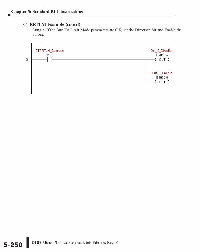
DL05 Micro PLC User Manual, 6th Edition, Rev. E5-250
Chapter 5: Standard RLL Instructions
CTRRTLM Example (cont’d)Rung 3: If the Run To Limit Mode parameters are OK, set the Direction Bit and Enable the output.

DL05 Micro PLC User Manual, 6th Edition, Rev. E 5-251
Chapter 5: Standard RLL Instructions
CTRIO Run to Position Mode (CTRRTPM) (IB-1012)CTRIO Run To Position Mode, on a leading edge transition to this IBox, loads the Run to Position command and given parameters on a specific Output resource.
Valid Function Values are:
00: Less Than Ch1/Fn1
10: Greater Than Ch1/Fn1
01: Less Than Ch1/Fn2
11: Greater Than Ch1/Fn2
02: Less Than Ch2/Fn1
12: Greater Than Ch2/Fn1
03: Less Than Ch2/Fn2
13: Greater Than Ch2/Fn2
This IBox will take more than 1 PLC scan to execute. Either the Success or Error bit will turn on when the command is complete. If the Error Bit is on, you can use the CTRIO Read Error Code (CTRRDER) IBox to get extended error information.
The Workspace register is for internal use by this IBox instruction and MUST NOT be used anywhere else in your program.
CTRRTPM Parameters
• CTRIO#: specifies a specific CTRIO module based on a user defined number (see CTRIO Config Ibox)
• Output#: specifies a CTRIO output to be used by the instruction
• Frequency: specifies the output pulse rate (H0-CTRIO: 20Hz - 25KHz / H0-CTRIO2: 20Hz - 250 KHz)
• Duty Cycle: specifies the % of on time versus off time. This is a hex number. Default of 0 is 50%, also entering 50 will yield 50%. 50% duty cycle is defined as on half the time and off half the time
• Position: specifies the count value, as measured on the encoder input, at which the output pulse train will be turned off
• Workspace: specifies a V-memory location that will be used by the instruction
• Success: specifies a bit that will turn on once the instruction has successfully completed
• Error: specifies a bit that will turn on if the instruction does not complete successfully
DS5 Used
HPP N/A
Parameter DL05 RangeCTRIO# ⸠⸠⸠⸠⸠⸠⸠⸠⸠⸠⸠⸠⸠⸠⸠⸠⸠⸠⸠⸠⸠⸠⸠⸠⸠⸠⸠⸠⸠⸠⸠⸠⸠⸠⸠⸠⸠⸠⸠⸠⸠⸠⸠⸠⸠⸠⸠⸠⸠⸠⸠⸠⸠⸠⸠⸠⸠⸠⸠⸠⸠⸠⸠⸠⸠⸠⸠⸠ K K0-255Output# ⸠⸠⸠⸠⸠⸠⸠⸠⸠⸠⸠⸠⸠⸠⸠⸠⸠⸠⸠⸠⸠⸠⸠⸠⸠⸠⸠⸠⸠⸠⸠⸠⸠⸠⸠⸠⸠⸠⸠⸠⸠⸠⸠⸠⸠⸠⸠⸠⸠⸠⸠⸠⸠⸠⸠⸠⸠⸠⸠⸠⸠⸠⸠⸠⸠⸠⸠ K K0-3Frequency ⸠⸠⸠⸠⸠⸠⸠⸠⸠⸠⸠⸠⸠⸠⸠⸠⸠⸠⸠⸠⸠⸠⸠⸠⸠⸠⸠⸠⸠⸠⸠⸠⸠⸠⸠⸠⸠⸠⸠⸠⸠⸠⸠⸠⸠⸠⸠⸠⸠⸠⸠⸠⸠⸠⸠⸠⸠⸠⸠⸠⸠V,K K20-20000; See DL05 V-memory map - Data WordsDuty Cycle ⸠⸠⸠⸠⸠⸠⸠⸠⸠⸠⸠⸠⸠⸠⸠⸠⸠⸠⸠⸠⸠⸠⸠⸠⸠⸠⸠⸠⸠⸠⸠⸠⸠⸠⸠⸠⸠⸠⸠⸠⸠⸠⸠⸠⸠⸠⸠⸠⸠⸠⸠⸠⸠⸠⸠⸠⸠⸠⸠⸠V,K K0-99; See DL05 V-memory mapPosition ⸠⸠⸠⸠⸠⸠⸠⸠⸠⸠⸠⸠⸠⸠⸠⸠⸠⸠⸠⸠⸠⸠⸠⸠⸠⸠⸠⸠⸠⸠⸠⸠⸠⸠⸠⸠⸠⸠⸠⸠⸠⸠⸠⸠⸠⸠⸠⸠⸠⸠⸠⸠⸠⸠⸠⸠⸠⸠⸠⸠⸠⸠⸠⸠V,K K0-2147434528; See DL05 V-memory mapWorkspace ⸠⸠⸠⸠⸠⸠⸠⸠⸠⸠⸠⸠⸠⸠⸠⸠⸠⸠⸠⸠⸠⸠⸠⸠⸠⸠⸠⸠⸠⸠⸠⸠⸠⸠⸠⸠⸠⸠⸠⸠⸠⸠⸠⸠⸠⸠⸠⸠⸠⸠⸠⸠⸠⸠⸠⸠⸠⸠⸠⸠⸠⸠ V See DL05 V-memory map - Data WordsSuccess ⸠⸠⸠⸠⸠⸠⸠⸠⸠⸠⸠⸠⸠⸠⸠⸠⸠⸠⸠⸠⸠⸠⸠⸠⸠⸠⸠⸠⸠⸠⸠⸠⸠⸠⸠⸠⸠⸠⸠⸠⸠⸠⸠⸠⸠ X,Y,C,GX,GY,B See DL05 V-memory mapError ⸠⸠⸠⸠⸠⸠⸠⸠⸠⸠⸠⸠⸠⸠⸠⸠⸠⸠⸠⸠⸠⸠⸠⸠⸠⸠⸠⸠⸠⸠⸠⸠⸠⸠⸠⸠⸠⸠⸠⸠⸠⸠⸠⸠⸠⸠⸠⸠⸠⸠ X,Y,C,GX,GY,B See DL05 V-memory map
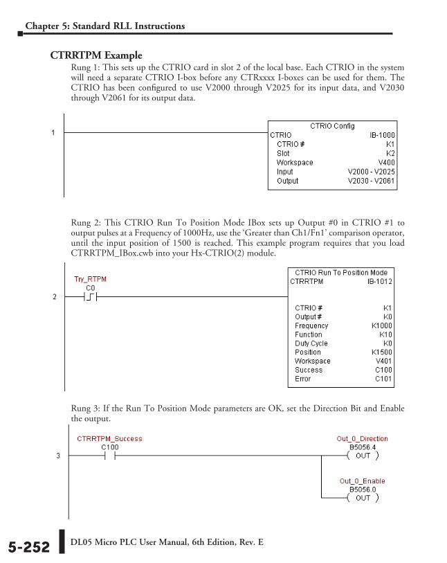
DL05 Micro PLC User Manual, 6th Edition, Rev. E5-252
Chapter 5: Standard RLL Instructions
CTRRTPM ExampleRung 1: This sets up the CTRIO card in slot 2 of the local base. Each CTRIO in the system will need a separate CTRIO I-box before any CTRxxxx I-boxes can be used for them. The CTRIO has been configured to use V2000 through V2025 for its input data, and V2030 through V2061 for its output data.
Rung 2: This CTRIO Run To Position Mode IBox sets up Output #0 in CTRIO #1 to output pulses at a Frequency of 1000Hz, use the ‘Greater than Ch1/Fn1’ comparison operator, until the input position of 1500 is reached. This example program requires that you load CTRRTPM_IBox.cwb into your Hx-CTRIO(2) module.
Rung 3: If the Run To Position Mode parameters are OK, set the Direction Bit and Enable the output.

DL05 Micro PLC User Manual, 6th Edition, Rev. E 5-253
Chapter 5: Standard RLL Instructions
CTRIO Velocity Mode (CTRVELO) (IB-1013)CTRIO Velocity Mode loads the Velocity command and given parameters on a specific Output resource on a leading edge transition to this IBox.
This IBox will take more than 1 PLC scan to execute. Either the Success or Error bit will turn on when the command is complete. If the Error Bit is on, you can use the CTRIO Read Error Code (CTRRDER) IBox to get extended error information.
The Workspace register is for internal use by this IBox instruction and MUST NOT be used anywhere else in your program.
CTRVELO Parameters
• CTRIO#: specifies a specific CTRIO module based on a user defined number (see CTRIO Config Ibox)
• Output#: specifies a CTRIO output to be used by the instruction
• Frequency: specifies the output pulse rate (H0-CTRIO: 20Hz - 25kHz / H0-CTRIO2: 20Hz–250kHz)
• Duty Cycle: specifies the % of on time versus off time. This is a hex number. Default of 0 is 50%, also entering 50 will yield 50%. 50% duty cycle is defined as on half the time and off half the time
• Step Count: This DWORD values specifies the number of pulses to output. A Step Count value of -1 (or 0xFFFFFFFF) causes the CTRIO to output pulses continuously. Negative Step Count values must be V-Memory references.
• Workspace: specifies a V-memory location that will be used by the instruction
• Success: specifies a bit that will turn on once the instruction has successfully completed
• Error: specifies a bit that will turn on if the instruction does not complete successfully
DS5 Used
HPP N/A
Parameter DL05 RangeCTRIO# ⸠⸠⸠⸠⸠⸠⸠⸠⸠⸠⸠⸠⸠⸠⸠⸠⸠⸠⸠⸠⸠⸠⸠⸠⸠⸠⸠⸠⸠⸠⸠⸠⸠⸠⸠⸠⸠⸠⸠⸠⸠⸠⸠⸠⸠⸠⸠⸠⸠⸠⸠⸠⸠⸠⸠⸠⸠⸠⸠⸠⸠⸠⸠⸠⸠⸠⸠⸠ K K0-255Output# ⸠⸠⸠⸠⸠⸠⸠⸠⸠⸠⸠⸠⸠⸠⸠⸠⸠⸠⸠⸠⸠⸠⸠⸠⸠⸠⸠⸠⸠⸠⸠⸠⸠⸠⸠⸠⸠⸠⸠⸠⸠⸠⸠⸠⸠⸠⸠⸠⸠⸠⸠⸠⸠⸠⸠⸠⸠⸠⸠⸠⸠⸠⸠⸠⸠⸠⸠ K K0-3Frequency ⸠⸠⸠⸠⸠⸠⸠⸠⸠⸠⸠⸠⸠⸠⸠⸠⸠⸠⸠⸠⸠⸠⸠⸠⸠⸠⸠⸠⸠⸠⸠⸠⸠⸠⸠⸠⸠⸠⸠⸠⸠⸠⸠⸠⸠⸠⸠⸠⸠⸠⸠⸠⸠⸠⸠⸠⸠⸠⸠⸠⸠V,K K20-20000; See DL05 V-memory map - Data WordsDuty Cycle ⸠⸠⸠⸠⸠⸠⸠⸠⸠⸠⸠⸠⸠⸠⸠⸠⸠⸠⸠⸠⸠⸠⸠⸠⸠⸠⸠⸠⸠⸠⸠⸠⸠⸠⸠⸠⸠⸠⸠⸠⸠⸠⸠⸠⸠⸠⸠⸠⸠⸠⸠⸠⸠⸠⸠⸠⸠⸠⸠⸠V,K K0-99; See DL05 V-memory mapStep Count ⸠⸠⸠⸠⸠⸠⸠⸠⸠⸠⸠⸠⸠⸠⸠⸠⸠⸠⸠⸠⸠⸠⸠⸠⸠⸠⸠⸠⸠⸠⸠⸠⸠⸠⸠⸠⸠⸠⸠⸠⸠⸠⸠⸠⸠⸠⸠⸠⸠⸠⸠⸠⸠⸠⸠⸠⸠⸠⸠V,K K0-2147434528; See DL05 V-memory mapWorkspace ⸠⸠⸠⸠⸠⸠⸠⸠⸠⸠⸠⸠⸠⸠⸠⸠⸠⸠⸠⸠⸠⸠⸠⸠⸠⸠⸠⸠⸠⸠⸠⸠⸠⸠⸠⸠⸠⸠⸠⸠⸠⸠⸠⸠⸠⸠⸠⸠⸠⸠⸠⸠⸠⸠⸠⸠⸠⸠⸠⸠⸠⸠ V See DL05 V-memory map - Data WordsSuccess ⸠⸠⸠⸠⸠⸠⸠⸠⸠⸠⸠⸠⸠⸠⸠⸠⸠⸠⸠⸠⸠⸠⸠⸠⸠⸠⸠⸠⸠⸠⸠⸠⸠⸠⸠⸠⸠⸠⸠⸠⸠⸠⸠⸠⸠ X,Y,C,GX,GY,B See DL05 V-memory mapError ⸠⸠⸠⸠⸠⸠⸠⸠⸠⸠⸠⸠⸠⸠⸠⸠⸠⸠⸠⸠⸠⸠⸠⸠⸠⸠⸠⸠⸠⸠⸠⸠⸠⸠⸠⸠⸠⸠⸠⸠⸠⸠⸠⸠⸠⸠⸠⸠⸠⸠ X,Y,C,GX,GY,B See DL05 V-memory map
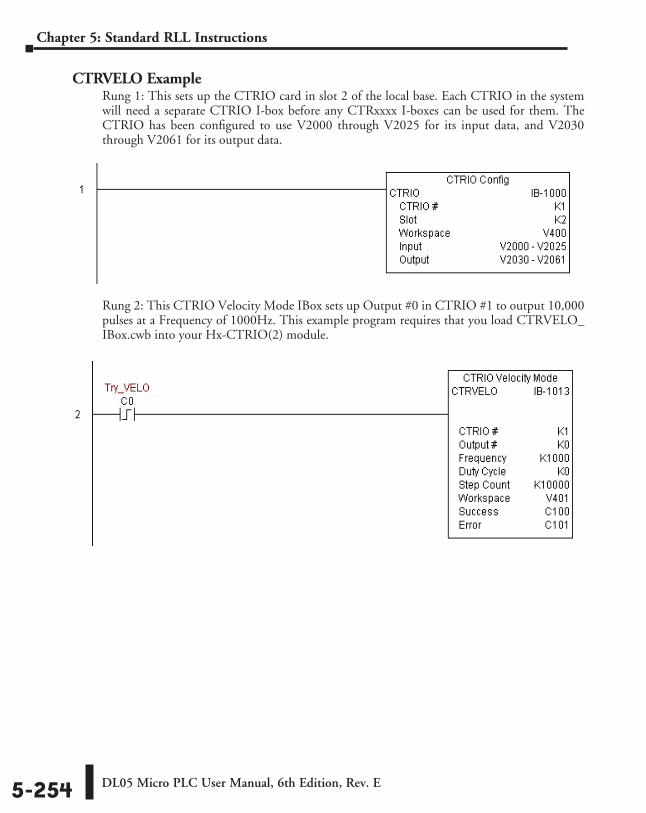
DL05 Micro PLC User Manual, 6th Edition, Rev. E5-254
Chapter 5: Standard RLL Instructions
CTRVELO ExampleRung 1: This sets up the CTRIO card in slot 2 of the local base. Each CTRIO in the system will need a separate CTRIO I-box before any CTRxxxx I-boxes can be used for them. The CTRIO has been configured to use V2000 through V2025 for its input data, and V2030 through V2061 for its output data.
Rung 2: This CTRIO Velocity Mode IBox sets up Output #0 in CTRIO #1 to output 10,000 pulses at a Frequency of 1000Hz. This example program requires that you load CTRVELO_IBox.cwb into your Hx-CTRIO(2) module.
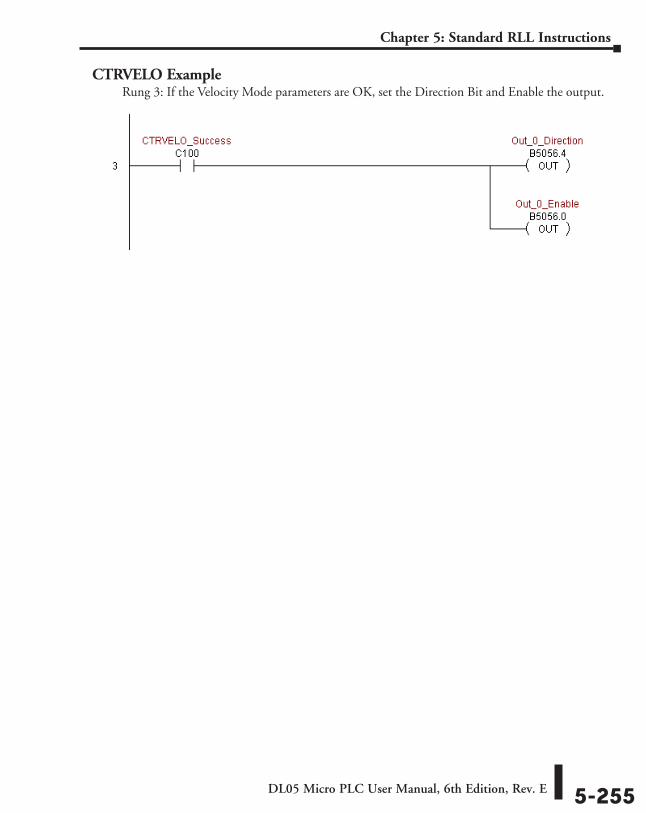
DL05 Micro PLC User Manual, 6th Edition, Rev. E 5-255
Chapter 5: Standard RLL Instructions
CTRVELO ExampleRung 3: If the Velocity Mode parameters are OK, set the Direction Bit and Enable the output.
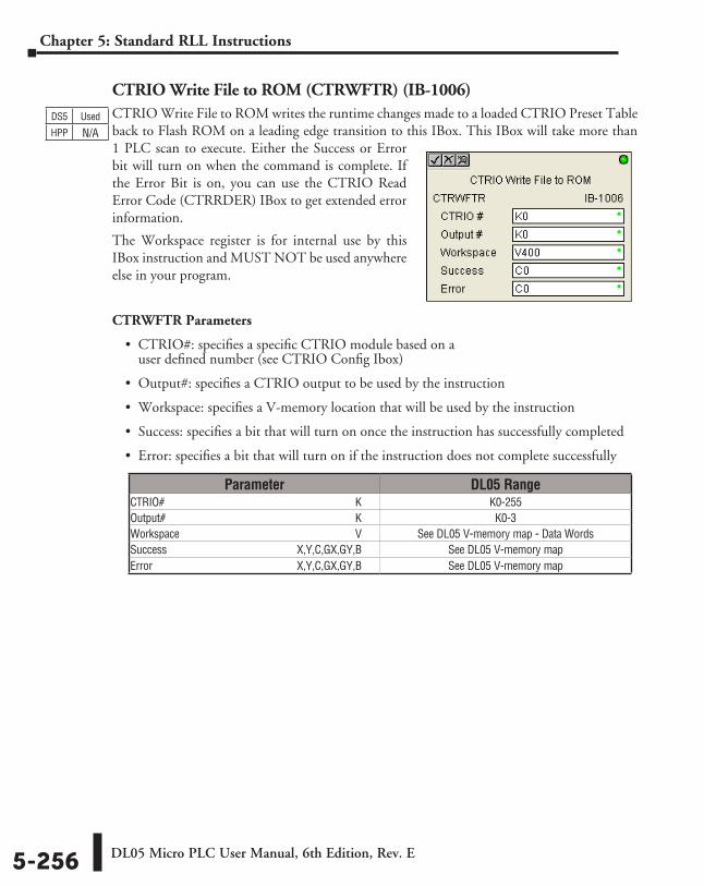
DL05 Micro PLC User Manual, 6th Edition, Rev. E5-256
Chapter 5: Standard RLL Instructions
CTRIO Write File to ROM (CTRWFTR) (IB-1006)CTRIO Write File to ROM writes the runtime changes made to a loaded CTRIO Preset Table back to Flash ROM on a leading edge transition to this IBox. This IBox will take more than 1 PLC scan to execute. Either the Success or Error bit will turn on when the command is complete. If the Error Bit is on, you can use the CTRIO Read Error Code (CTRRDER) IBox to get extended error information.
The Workspace register is for internal use by this IBox instruction and MUST NOT be used anywhere else in your program.
CTRWFTR Parameters
• CTRIO#: specifies a specific CTRIO module based on a user defined number (see CTRIO Config Ibox)
• Output#: specifies a CTRIO output to be used by the instruction
• Workspace: specifies a V-memory location that will be used by the instruction
• Success: specifies a bit that will turn on once the instruction has successfully completed
• Error: specifies a bit that will turn on if the instruction does not complete successfully
DS5 Used
HPP N/A
Parameter DL05 RangeCTRIO# ⸠⸠⸠⸠⸠⸠⸠⸠⸠⸠⸠⸠⸠⸠⸠⸠⸠⸠⸠⸠⸠⸠⸠⸠⸠⸠⸠⸠⸠⸠⸠⸠⸠⸠⸠⸠⸠⸠⸠⸠⸠⸠⸠⸠⸠⸠⸠⸠⸠⸠⸠⸠⸠⸠⸠⸠⸠⸠⸠⸠⸠⸠⸠⸠⸠⸠⸠⸠ K K0-255Output# ⸠⸠⸠⸠⸠⸠⸠⸠⸠⸠⸠⸠⸠⸠⸠⸠⸠⸠⸠⸠⸠⸠⸠⸠⸠⸠⸠⸠⸠⸠⸠⸠⸠⸠⸠⸠⸠⸠⸠⸠⸠⸠⸠⸠⸠⸠⸠⸠⸠⸠⸠⸠⸠⸠⸠⸠⸠⸠⸠⸠⸠⸠⸠⸠⸠⸠⸠ K K0-3Workspace ⸠⸠⸠⸠⸠⸠⸠⸠⸠⸠⸠⸠⸠⸠⸠⸠⸠⸠⸠⸠⸠⸠⸠⸠⸠⸠⸠⸠⸠⸠⸠⸠⸠⸠⸠⸠⸠⸠⸠⸠⸠⸠⸠⸠⸠⸠⸠⸠⸠⸠⸠⸠⸠⸠⸠⸠⸠⸠⸠⸠⸠⸠ V See DL05 V-memory map - Data WordsSuccess ⸠⸠⸠⸠⸠⸠⸠⸠⸠⸠⸠⸠⸠⸠⸠⸠⸠⸠⸠⸠⸠⸠⸠⸠⸠⸠⸠⸠⸠⸠⸠⸠⸠⸠⸠⸠⸠⸠⸠⸠⸠⸠⸠⸠⸠ X,Y,C,GX,GY,B See DL05 V-memory mapError ⸠⸠⸠⸠⸠⸠⸠⸠⸠⸠⸠⸠⸠⸠⸠⸠⸠⸠⸠⸠⸠⸠⸠⸠⸠⸠⸠⸠⸠⸠⸠⸠⸠⸠⸠⸠⸠⸠⸠⸠⸠⸠⸠⸠⸠⸠⸠⸠⸠⸠ X,Y,C,GX,GY,B See DL05 V-memory map
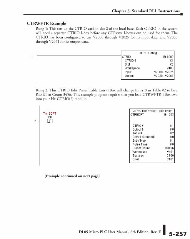
DL05 Micro PLC User Manual, 6th Edition, Rev. E 5-257
Chapter 5: Standard RLL Instructions
CTRWFTR ExampleRung 1: This sets up the CTRIO card in slot 2 of the local base. Each CTRIO in the system will need a separate CTRIO I-box before any CTRxxxx I-boxes can be used for them. The CTRIO has been configured to use V2000 through V2025 for its input data, and V2030 through V2061 for its output data.
Rung 2: This CTRIO Edit Preset Table Entry IBox will change Entry 0 in Table #2 to be a RESET at Count 3456. This example program requires that you load CTRWFTR_IBox.cwb into your Hx-CTRIO(2) module.
(Example continued on next page)
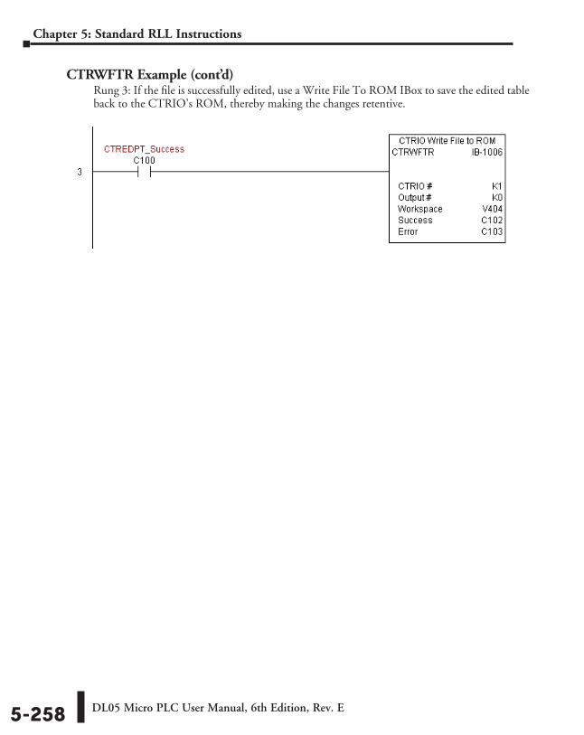
DL05 Micro PLC User Manual, 6th Edition, Rev. E5-258
Chapter 5: Standard RLL Instructions
CTRWFTR Example (cont’d)Rung 3: If the file is successfully edited, use a Write File To ROM IBox to save the edited table back to the CTRIO’s ROM, thereby making the changes retentive.