in this issue fly-away rail guides revisited · issue 387 march 24, 2015 page 3 fly-away rail...
TRANSCRIPT

I S S U E 3 8 7 M A R C H 2 4 , 2 0 1 5
Apogee Components, Inc. — Your Source For Rocket Supplies That Will Take You To The “Peak-of-Flight”3355 Fillmore Ridge Heights
Colorado Springs, Colorado 80907-9024 USAwww.ApogeeRockets.com e-mail: [email protected]
Phone: 719-535-9335 Fax: 719-534-9050
Fly-Away Rail Guides Revisited
Shrox Plan: DetlanX
In This Issue
Cover Photo: North Coast Rocketry’s SA-14 Archer ready to launch. Get your own at: https://www.apogeerockets.com/Rocket_Kits/Skill_Level_3_Kits/SA-14_Archer
Page 2 I S S U E 3 8 7 M A R C H 2 4 , 2 0 1 5
You can subscribe to receive this e-zine FREE at the Apogee Components web site (www.ApogeeRockets.com), or by sending an e-mail to: [email protected] with “SUB-SCRIBE” as the subject line of the message.
About this Newsletter Newsletter Staff
Writer: Tim Van MilliganLayout / Cover Artist: Tim Van MilliganProofreader: Michelle Mason
By Tim Van Milligan
Continued on page 3
Out on the competition range, I am still the only person that seems to be using the fly-away rail guides. But over on the high power range, I’m starting to see some folks using them for bigger rockets.
Bill Cook seems to be the gentleman leading the way on the use of fly-away rail guides for bigger rockets. And in this issue, I thought I’d show some of Bill’s designs, as well as my own refinements.
First of all, if you need some back-ground on the fly-away rail guides, see Peak-of-Flight Newsletter #243 (www.ApogeeRockets.com/education/downloads/Newsletter243.pdf) and my 2010 R&D report on my web site. You’ll find it at: https://www.apogeerockets.com/downloads/PDFs/De-velopment_of_Rail_Guides.pdf. But that is the past... this is what has happened since.
I actually found out about Bill’s work on the Rocketry Forum just a couple of days ago (http://www.rocketryfo-rum.com/showthread.php?121667-Fly-away-rail-guides-*AVAILABLE-SOON*-38mm-3D-printed). I was showing my latest revisions to the fly away rail guides to a friend of mine, and he pointed me to the discussion online. It was spooky that Bill was making some of the same discoveries that I had independently made, but at the same time was doing some really cool things.
Note: I haven’t talked to Bill for this article, so I’ll be
referencing the pictures he posted on the Rocketry Forum.
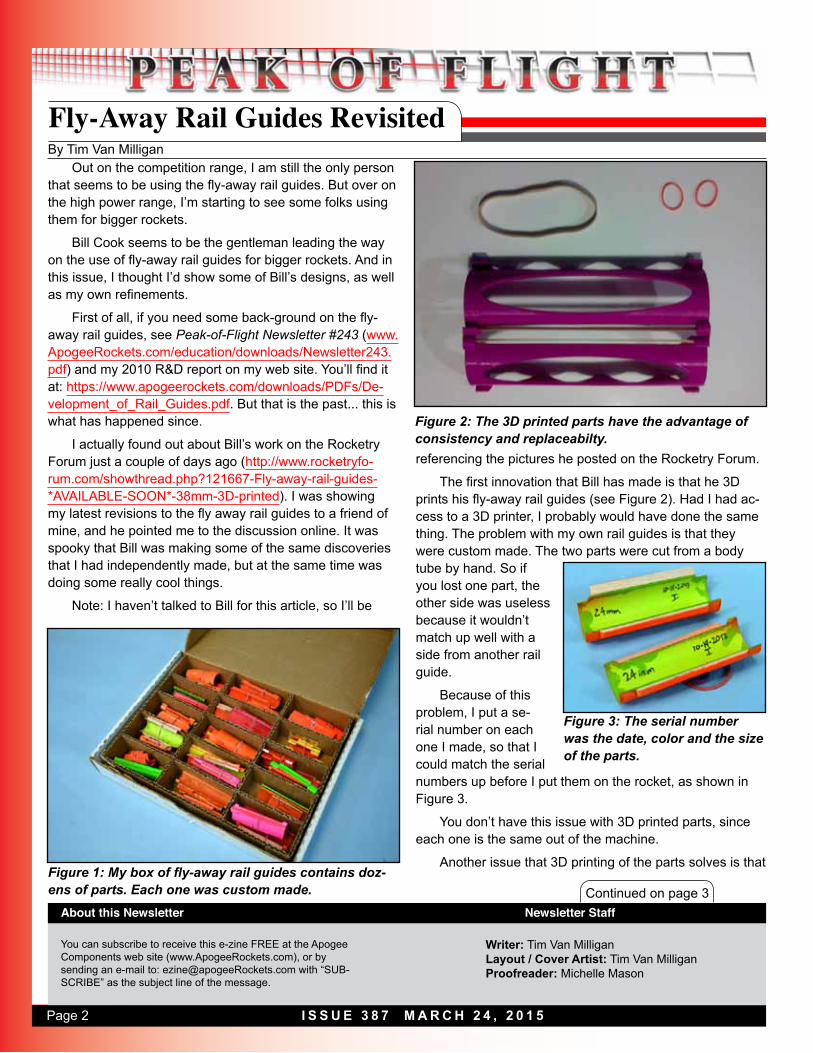
The first innovation that Bill has made is that he 3D prints his fly-away rail guides (see Figure 2). Had I had ac-cess to a 3D printer, I probably would have done the same thing. The problem with my own rail guides is that they were custom made. The two parts were cut from a body tube by hand. So if you lost one part, the other side was useless because it wouldn’t match up well with a side from another rail guide.
Because of this problem, I put a se-rial number on each one I made, so that I could match the serial numbers up before I put them on the rocket, as shown in Figure 3.
You don’t have this issue with 3D printed parts, since each one is the same out of the machine.
Another issue that 3D printing of the parts solves is that
Fly-Away Rail Guides Revisited
Figure 1: My box of fly-away rail guides contains doz-ens of parts. Each one was custom made.
Figure 2: The 3D printed parts have the advantage of consistency and replaceabilty.
Figure 3: The serial number was the date, color and the size of the parts.

Page 3I S S U E 3 8 7 M A R C H 2 4 , 2 0 1 5
Fly-Away Rail Guides RevisitedContinued from page 2
Continued on page 4
of warping due to changes in humidity. Because mine were made from paper, over time they would deform because of humidity in the air. This is disasterous, because the fit of the fly-away rail guides onto the rocket is critical. If they are too loose, they don’t grip the rocket properly, and then they don’t work right. I’ve lost fly-away rail guides that were returned to me later by people who found them on the field. They thought that they were still usable; but because the dew from the grass got into the paper, they were useless. I chucked them as soon as I found the nearest garbage can.
Additionally, my own fly-away rail guides were time-consuming to make by hand. I probably invested about 20 minutes per set making them. While 3D printing is not exactly quick, you don’t have to be around for the machine to build up the plastic to the right shape. Your own time is better utilized by doing something else.
Finally, the 3D parts could be made out of flourescent colors, which makes them easier to find after the flight. Printing them in the right color saves the step of having to come back later to make them more visible with spray paint.
As I was reading Bill’s internet posts describing the development of the 3D printed cradles, I could see he was having the same issues that I had. His original designs had the cradles only going part-way around the rocket, and the rubber band making up the circumference difference (see Figure 4). It was like deja-vu seeing this, because I did the same thing on my first designs.
The issue is that the rubber band pulls the cradles together, and tightens the fit of the guides in the rail. They rub hard on the inside edges of the launch rail.
It didn’t take either of us long to figure out that the cradles must fit all the way around the rocket, to minimize the rubber bands trying to open them up while the rocket was still on the launch rail.
You’ll see in Figure 5 that Bill’s latest designs go all the way around the rocket, and keep the rubber band off the surface of the rocket.
The other really nice feature that he added is to hinge the two cradles together. So when they fly off the rocket, the pieces stay together. It is much easier to
Model Rocket Design and ConstructionBy Timothy S. Van Milligan
The Expanded 3rd Edition
Apogee Components3355 Fillmore Ridge HeightsColorado Springs, Colorado 80907
telephone: 719-535-9335website: www.ApogeeRockets.com
This massive, 328 page guidebook for serious rocket designers contains the most up-to-date information on creating unique and exciting models that really work. With 566 illustrations and 175 photos, it is the ultimate resource if you want to make rockets that will push the edge of the per-formance envelope. Because of the number of pictures, it is also a great gift to give to beginners to start them on their rocketry future.
For more information, and to order this hefty book, visit the Apogee web site at: www.ApogeeRockets.com
Figure 4: The rubber band on Bill’s original design was used to grip the tube. The cradles didn’t go all the way around the tube.

Page 4 I S S U E 3 8 7 M A R C H 2 4 , 2 0 1 5
Continued from page 3
Fly-Away Rail Guides Revisited
Continued on page 5
find one large part on the ground after the flight than to search around for two smaller pieces.
One other change that Bill made, and some-thing I independen-tally discovered, was to move the location of the rub-ber band. Previous-ly, I had the rubber wrapping around the perimeter of the cradles (see Figure 6). This worked, but only because the rubber band was laying on the pivot point between the two cradles. As Bill makes so clear in his internet
posts, the location of the rubber band in relation to the pivot point is what controls how easily it is for the cradles to stay closed while the rocket is on the launch rail.
As discussed previously, there is a conflict here. The rubber band is trying to open up the cradles while it is still on the rail. Because it wants to open up, there is extra fric-tion at the location where the fingers touch the inside of the rail.
Obviously, you want as little friction as possible, so the rocket slides easily up the rail. The friction can be mini-
Staging Electronics• Designed to ignite the top motor in two-stage rockets.
• Provides an easy way to stage composite propel-
lant motors
ww
w.A
pogeeRock
ets.co
m
• Fires off igniters after a preprogrammed amount of
time following liftoff• G-switch senses liftoff and
insures against a false launch-detection
• Small, lightweight design is great for skinny rockets
• Easy-to-use, and will fire off any ig-niter, including clusters!
www.ApogeeRockets.comBattery, battery connector, mounting board and igniter are not incuded.
Figure 5: The hinge on the side op-posite the rail is a nice feature.
Figure 6: I originally had a rubber band wrap around the cradles to pull them open.

Page 5I S S U E 3 8 7 M A R C H 2 4 , 2 0 1 5
Continued from page 4
Fly-Away Rail Guides Revisited
Continued on page 6
mized by using a weaker rubber band, but then the device doesn’t spring open quickly after the rocket leaves the rail.
So positioning the rubber band is very important. I’ll explain this shortly. But first, what have I been doing differ-ently since my original designs?
Nails and HammersThere is a saying: “If your only tool is a hammer, every-
thing looks like a nail.”
That defines my approach to the continued develop-ment of the fly-away rail guides. I don’t have a 3D printer tool like Bill has. But I do have a laser cutter (see Peak-of-Flight Newsletter #366 at: www.apogeerockets.com/education/downloads/Newsletter366.pdf). So I thought I’d try cutting some of the pieces out of plywood instead of making them by hand.
My first laser-cut design was a profile of the my original design. I had the rubber band hooks in the same location as I had them before (similar to Figure 6). Unfortunately, it didn’t work very well. Since the wood profile was much thicker than the original paper tube, the rubber band was pulling the fingers apart too hard, and there was a lot of fric-tion as it slid along the rail.
So I played with the location of the rubber band attach-ment points, and eventually I settled on the fact that they must span just slightly over the pivot point of the two cradle halves as shown in Figure 7. It was only by trial and error
that I figured this out. But thanks to the speed of the laser-cutter, it was a relatively quick to go through several design iterations.
Once I had the rubber band position dialed in, I next went to work on the other issues. I really wanted to have the pieces cut from a single piece of wood. That way, if I lost a half, it wouldn’t be a big issue. I didn’t mind having a disposable part, since I hadn’t invested any construction time making it. The laser was doing all the work.
But the parts wouldn’t stay together when wrapped around the rocket. Especially when you slid them into the
Cesaroni Reload Motors
ww
w.A
pogeeRock
ets.co
m
• Standard Sizes Fit Your Existing Fleet• Easy Assembly, Minimal Clean-up• Casings & Propellant Available• Adjustable Ejection Delays• 9 Propellant Formulations
ApogeeRockets.com/Rocket_Motors/Cesaroni_Casings
Pro-XA better way to fly.™Kick Your Rockets Into High Gear
Starter Packs Available!
Your Source For Everything R
ocketry
Figure 7: My first successful laser-cut design. The rubber band attachment points (pink arrows) are just barely further from the center of the tube as the pivot point (yellow arrow).

Page 6 I S S U E 3 8 7 M A R C H 2 4 , 2 0 1 5
Continued on page 7
Continued from page 5
Fly-Away Rail Guides Revisitedlaunch rail. The jostling of the parts would make them slide off of each other. They needed to be thicker. So I tried thicker plywood. But is still wasn’t thick enough to keep them lined up.
I eventally went back to a cradle system, so that the edges would stay together when sliding it onto a rail. These (shown in Figure 8) were the ones that I was showing to my friend the other day before he told me about the 3D printed ones that Bill Cook had made.
The parts still have to be glued together, which takes about two minutes to do. This is considerably faster than my old version. And they are now interchangeable.
I also added a little channel for the rubber band to seat into, which prevents them from coming apart when they spring off the rocket. So I’m no longer looking for two parts
on the ground, I just need to find one, just like Bill’s design.
Figure 9 shows the position of the rubber band in relation to the pivot point. There is very little force trying to open the cradles while the rocket is engaged in the rail. But once the rocket is free, that opening force really increases once they start to open. This is what Bill is trying to point out in his videos on youtube that describe his 3D printed fly-away rail guides such as the one at: https://www.you-tube.com/watch?v=h4lqfWXD0Sg.
I have test flown several different sizes so far, and they all seem to work great.
But I still think there is a little bit of room for improve-
AltimeterOne
ww
w.A
pogeeRock
ets.co
mYour Source For Everything
Rock
etry
• Records peak speed and acceleration using 3-axis accelerometer.
• Also tells you how high the rocket flew.
“The one altimeter you’ll use in every rocket you fly.”
AltimeterOne - See how high your rocket flew
Penny shown for size comparisonwww.ApogeeRockets.com
AltimeterTwo - See how fast and high your rocket went
• Records peak altitude up to 29,000 feet (ASL). Displays in meters too!
• Easy-to-read LCD display. No need to count beeps or flashes of light.
Figure 8: The latest version of the laser-cut cradles.
Figure 9: The rubber band force trying to pry open the fly-away rail guides increases as they open because the fulcum distance increases.

Page 7I S S U E 3 8 7 M A R C H 2 4 , 2 0 1 5
Continued from page 6
Fly-Away Rail Guides Revisited
ww
w.A
pogeeRock
ets.co
m
Egg-Payload Protectors• Soft, flexible foam padding provides
superior protection from cracking• Conforms to the egg to eliminate
pressure points
• TARC style for two eggs available
• Lightweight & reusableMade by:
ment.
ImprovementsThe biggest challenge right now is the fit of the cradles
on the rocket itself. As mentioned previously, the cradles need to completely wrap around the perimeter of the rock-et. But that fit is important. If the cradles are too tight, then the cradles don’t close all the way, and the fingers want to start spreading and increase the friction in the rail. If they are too loose, then the rocket can slide through them. Of course, they’re going to eventually butt up against the front root-edge of the fins and then go up with the rocket.
This isn’t a big issue on large rockets that have ply-wood fins. But on the small competition rockets that I’m typically flying, ram-ming the soft balsa fins into the cradles does deform the leading edge of the fins. That smooshes them, and then they have a lot of drag. As you can imagine, that defeats the purpose of having fly-
away rail guides.
One of my ideas to prevent this is to purposely deform the paper tube of the rocket as the cradles are put on (see Figure 10).
The inside perimeter of the cradles stays the same (as if the rocket’s tube was a perfect circle), but the tube is turned into a slight oval shape. Then the cradles would always grip the tube.
Of course, this wouldn’t work on stiff high-power tubes, like those made from fiberglass. They are too stiff to de-form. But is should work on small paper tubes.
References: Bill Cook’s 3D printed fly-away rail guides are being sold at the Animal Motor Works web site: http://cart.amwprox.com/index.php?option=com_virtuemart&view=productdetails&virtuemart_product_id=879&virtuemart_category_id=18&Itemid=435
About the AuthorTim Van Milligan (a.k.a. “Mr. Rocket”) is a real rocket
scientist who likes helping out other rocketeers. Before he started writing articles and books about rocketry, he worked on the Delta II rocket that launched satellites into orbit. He has a B.S. in Aeronautical Engineering from Embry-Riddle Aeronautical University in Daytona Beach, Florida, and has worked toward a M.S. in Space Technology from the Florida Institute of Technology in Melbourne, Florida. Cur-rently, he is the owner of Apogee Components (http://www.apogeerockets.com) and the curator of the rocketry educa-tion web site: http://www.apogeerockets.com/education/. He is also the author of the books: “Model Rocket Design and Construction,” “69 Simple Science Fair Projects with Model Rockets: Aeronautics” and publisher of a FREE e-zine newsletter about model rockets. Figure 10: Deforming the tube may
be a way to increase the grip with-out changing the function.
Page 8 I S S U E 3 8 7 M A R C H 2 4 , 2 0 1 5
By Shrox
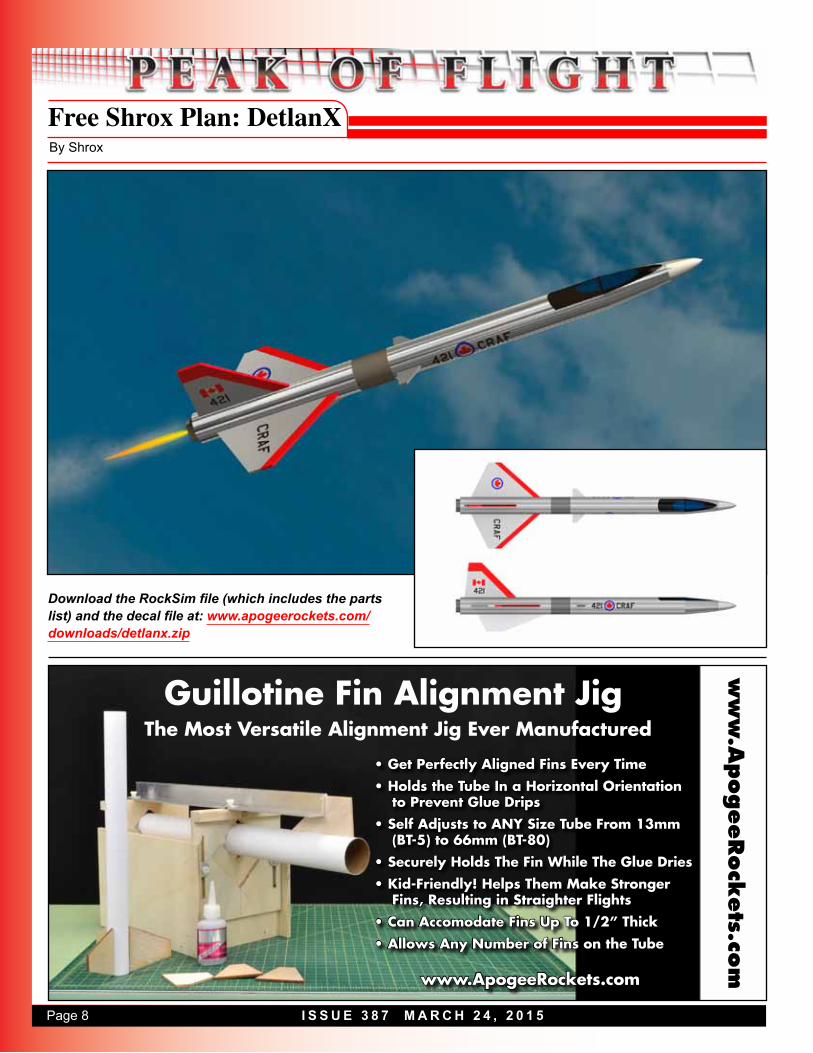
Free Shrox Plan: DetlanXw
ww
.ApogeeRock
ets.co
m
Guillotine Fin Alignment Jig
• Get Perfectly Aligned Fins Every Time• Holds the Tube In a Horizontal Orientation
to Prevent Glue Drips• Self Adjusts to ANY Size Tube From 13mm
(BT-5) to 66mm (BT-80) • Securely Holds The Fin While The Glue Dries• Kid-Friendly! Helps Them Make Stronger
Fins, Resulting in Straighter Flights • Can Accomodate Fins Up To 1/2” Thick • Allows Any Number of Fins on the Tube
www.ApogeeRockets.com
The Most Versatile Alignment Jig Ever Manufactured
Download the RockSim file (which includes the parts list) and the decal file at: www.apogeerockets.com/downloads/detlanx.zip