in this study,high-temperature fatigue tests with and
TRANSCRIPT

High temperature fatigue crack propagation
property of Mod.9Cr-lMo steel under vacuum
and air conditions
T. Ogata, M. Yamamoto
Central Research Institute of Electric Power Industry, Tokyo, Japan
Abstract
Micro-crack propagation behavior of Mod.9Cr-lMo steel under high-temperaturefatigue in vacuum and air conditions were periodically observed. Micro-crackspropagated in the direction normal to the stress axis in vacuum while theypropagated in the maximum shear direction in air conditon. It was found thatpropagation rate in air was faster than that in vacuum until the crack grew 1mmlength due to oxidation effect which was insignificant for the crack larger than1mm. Acceleration of the crack propagation rate in the compressive hold test wassupposed to be caused by accumulation of tensile strain in the center of thespecimen due to off-balance of strain distribution between the tension andcompression sides.
1. Introduction
Mod.9Cr-lMo steels is being used for high-temperature components in powerplants because of its superior high-temperature strength property. As creep-fatiguedamage gradually progresses during operation, the creep-fatigue damageevaluation methods for the steel have been intesively investigated. Previous studies[l]-[3] reported that fatigue life reduction under the compressive hold is muchlarger than that under the tensile hold. This tendency is different from austeniticstainless steels. It was suggested that the life reduction would be caused by theeffect of positive mean stress yeilding during compressive hold tests[l] oraccerelation of crack intiation and propagation rate due to the oxidation effect[2]. On the other hand, Ogata et. al.[3] indicated that the life reduction could notbe interpretted by the mean stress effect only and it happened even in vacuumconditon. Thus the reason of the feature is still controversial and uncertain.
Transactions on Engineering Sciences vol 13, © 1996 WIT Press, www.witpress.com, ISSN 1743-3533

592 Localized Damage
In this study,high-temperature fatigue tests with and without strain hold werecarried out in vacuum and in air enviroments and micro crack initiation andpropagation behavior, which dominates low-cycle fatigue life, was observedperiodically. Influence of enviroment on the micro crack propagation and a reasonof the life reduction in the compression hold were discussed.
2 Test procedure
Material used in this study was a Mod9Cr-lMo steel. Chemical compositon andmechanical property are shown in Table 1. The material was treated by quenchingand tempering followed by post welding heat treatment, 740°C and 504min. Aspecimen geometry is shown in Fig. 1 which is a solid bar with 10mm diameterand 10mm gauge length . In order to observe the crack intiation and propagationbehavior easily, a small notch of O.lmm diameter and deep was introduced byelectric discharge processing in the center of gauge length. A test equipment is anelectro-mechanical high-temperature fatigue testing machine with an inductionheating device. The testing machine used for tests in vacuum had a vacuumchamber and a turbo molecular exhausiton device. Degree of vacum is about 10* MPa. The test temperature was 550°C and strain waveforms were triangular,lOminutes. compression hold and 60minutes tension hold. Each test was stoppedat predetermined cycles to take replication film from the surface. Micro crackson the films were observed by an optical microscope.
Table 1: Chemical composition andmechanical property(a) Chemical composition wt(%)
c0.09
Si0.24
Mn0.44
p0.003
S0.001
Ni0.04
Cr8.78
Mo0.94
Nb0.08
V0.21
Al0.013
22 J 2(b) Mechanical property and heat treatment condition. [~ "̂
Mechanical propertiesProofStress(MPa)528.2
TensileStrength(MPa)629.9
Elon-gation(%)26.0
Red. ofArea(%)
70.0
Heat treatment conditionNormalizing 1060°C x 90min.Temper 760°C x 60min.SR 740°C x 504min.
L
Figure 1: Specimen geometry
3 Test results and discussion
3.1 Crack initiation and propagation behavior
The crack initiation and propagation behavior in vacuum and air enviromentsobserved by the optical microscope were shown in Fig. 2. Micro cracks initiatedfrom the notch in the direction normal to the stress axis both in vacuum and airconditions under the PP as shown in Fig 2(a). Number of cycles to the microcrack initiation from the notch in air conditon reduced to 1/10 compared fromvacuum. Duquett [4] reported that the fatigue crack initiation period in air reduced
Transactions on Engineering Sciences vol 13, © 1996 WIT Press, www.witpress.com, ISSN 1743-3533
Localized Damage 593
compared to vacuum conditon at room temperature due to the fact that the crackinitiation was caused by larger irreversible slip in air than that in vacuum due tooxidation of the created surface by cross slip motion. It is easy to imagine thatthe oxidation effect become significant at high-temperature where cracking ofoxidation film is likely to accelerate crack initiation at material surface. The micro-crack grew with branching and opening in the same direction as initiation invacuum condition whereas the propagation direction in air inclined about 45°fromthe initiation direction with branching cracks. Thus crack propagation behavioris different between vacuum and air conditions even under the same temperatureand loading conditions.
Figure 2(b) shows crack propagation behavior under 10 minutes compressionhold. A crack initiated from notch at 100 cycles in vacuum and slip bands aremore visible than those in air. When it compares with the PP waveform in vacuum,number of cycles to the crack initiation reduced to 1/10. It suggests that producingof a crack plane is accelerated by irreversible deformation in the assymmetricwaveform greater than that in the symmetric waveform. Althoug the crack initiationcycles are almost the same both in vacuum and in air conditons, propagation ratein vacuum is slower than that in air and ductile opening of the crack was occurredby elongating the notch after 1000 cycles. On the other hand, number of cycles tocrack initiation under the compression hold in air is nearly equal to those in thePP. As same as observed in PP, the crack propagation direction changed to about45 ° from the direction normal to the stress axis. Crack opening displacementincreased after 500 hours due to accumulation of irreversible shear deformationto the tensile direction in spite of the compression hold. It is suggested that thetensile residual strain accumulated in the center of the specimen due toconcentration of plastic deformation during tensile loading after strainredistribution by creep deformation during compression hold period.
In the tension hold tests, the notch was elongated to the direction normal tothe stress axis. In this case, the compressive strain was seemed to be accumulatedin the center of the specimen. Crack initiation period in air was longer than thatunder the compression hold. Crack propagation rate is also slower in the tensionhold than that in the compression hold. It is considered that crack propagationresistance in the tension hold is larger than that in the compression hold due tothe residual compressive stress effect at the crack surface.
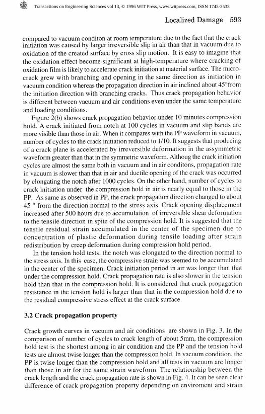
3.2 Crack propagation property
Crack growth curves in vacuum and air conditions are shown in Fig. 3. In thecomparison of number of cycles to crack length of about 5mm, the compressionhold test is the shortest among in air condition and the PP and the tension holdtests are almost twise longer than the compression hold. In vacuum condition, thePP is twise longer than the compression hold and all tests in vacuum are longerthan those in air for the same strain waveform. The relationship between thecrack length and the crack propagation rate is shown in Fig. 4. It can be seen cleardifference of crack propagation property depending on environment and strain
Transactions on Engineering Sciences vol 13, © 1996 WIT Press, www.witpress.com, ISSN 1743-3533

594 Localized Damage
Stress axis
N = 0 N=2100 N = 3600
N = 0
Stress axis
N = 4500
N = 300 N = 700 N = 1000
(a) PP test (top:vacuum, bottom: air)
N = 0 N = 500 N = 1000 N = 1500
N = 0 N = 200 N = 300 N = 500
(b) Compression hold test(top:vacuum, bottom:air)
Figure 2 Crack intiation and propagation behavior form notch root
Transactions on Engineering Sciences vol 13, © 1996 WIT Press, www.witpress.com, ISSN 1743-3533

Localized Damage 595
5 -
Crack
length (mm)
o _L
ro o
*»
Air vacPP • O
Comp 10min A AA Ten 60min • ^
A m* ̂ 0
• 0
••A O
1000 2000 3000 4000 5000 6000Number of cycles 10
Fig.:
10*Crack length (mm)
propagationunder vacuum and air condition Fig-4: Relationship between crack
propagation rate and crack length
waveform. In the micro-crack shorter than 1mm in length, the crack propagationrate in air condition is faster than that in vacuum condition in the comparisonbetween the same strain waveforms. However difference of the crack propagationrate become small for the cracks larger than 1mm. This fact suggests that theoxidation effect on crack propagation rate is significant for the micro crack up to1mm in length but it become insignificant for larger cracks. Neumann[5] carriedout crack propagation tests of a copper and reported that although the crackpropagation rate accerelated by the oxidation at low crack propagation rate region(below 10 ̂ mm/cycle), the oxidation effect disappeared beyond the crackpropagation rate. In the comparison between waveforms, the crack propagationrate under the compression hold is the fastest both in vacuum and air conditionsand difference of the propagation rate between the compression hold and the PPincreases with increasing the crack length due to accumulation of the tensile strain.Accerelation of the crack propagation rate by creep during the tension hold couldnot be seen in air condition.
3.3 Crack propagation mechanism
Although as the microscopic failure and deformation at the crack tip were notobserved in this study, quantitative difference of a crack propagation mechanismbetween vacuum and air enviroment can not be clarified, the crack propagationmechanism in both enviroments will be discussed based on the macroscopicobservation results of the crack initiation and propagation behavior and previousstudies concerning the enviromental effect on the crack propagation property.Neumann[5] showed that a shear type stage I crack initiated in air changed to
opening mode in vacuum and the mode I crack propagation was explaned by themacro slip model in which a crack grows by separation of slip planes and crossslip at conjugation slip planes. Pelloux[6] indicated that the fatigue crack of an
Transactions on Engineering Sciences vol 13, © 1996 WIT Press, www.witpress.com, ISSN 1743-3533
596 Localized Damage
aluminum alloy in vacuum grew by repetation of the reversible slip and rebondingat the crack tip and crack extension during one cycle in vacuum is smaller thanthat in air where the crack grows by repetation of the irreversible slip. McEvilly[7]carried out crack propagation tests on 304 and 316 stainless steels in vacuum andair environments at room temperature and reported that the crack tip blunting waseasy to occurr in vacuum conditon whereas the crack tip was relatively sharp andpropagation rate is faster in air enviroment because of local strain concentrationat the crack plane due to irreversible slip.
Considering above discussion, the crack growth mechanism in vacuum seemsto be explaned by the separation of slip planes and the cross slip althogh difficultyof the cross slip and contribution of the separation of slip planes to the crackgrowth depends on the stacking fault energy of the material. The rebonding at thecrack plane was occurred in all materials in vacuum condition. In the airenviroment, the difference of the crack growth mechanism is identified as theirreversible slip and obstruction of the rebonding by oxidation layer at the cracktip, though the crack extension by the slip at the crack plane is the same as invacuum enviroment. Because of the fact as observed in Fig.2 that the crackpropagated in the direction normal to the stress axis in vacuum conditon andmany slip bands indicating slip direction could be seen, the fatigue crack growthmechanism of the steel in vacuum at high-temperature is seems to be the same asabove mentioned mechanism. On the other hand, the micro crack in the air conditonpropagated on the maximum shear plane macroscopically. It would be supposedthat the separation of the main slip plane caused by the irreversible slip in themotion of the main slip system at the crack tip is easy to occur and the motion ofthe conjugation slip system is prevented due to significant oxidation effect.
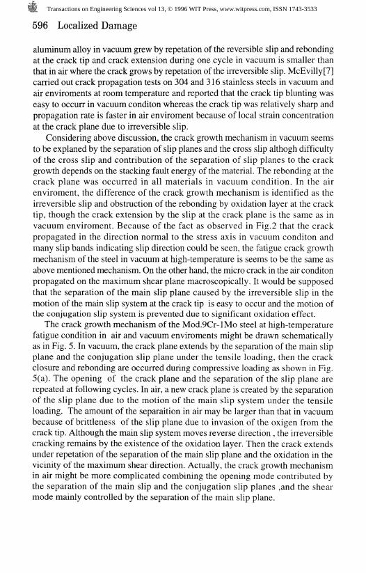
The crack growth mechanism of the Mod.9Cr-lMo steel at high-temperaturefatigue condition in air and vacuum environments might be drawn schematicallyas in Fig. 5. In vacuum, the crack plane extends by the separation of the main slipplane and the conjugation slip plane under the tensile loading, then the crackclosure and rebonding are occurred during compressive loading as shown in Fig.5(a). The opening of the crack plane and the separation of the slip plane arerepeated at following cycles. In air, a new crack plane is created by the separationof the slip plane due to the motion of the main slip system under the tensileloading. The amount of the separaition in air may be larger than that in vacuumbecause of brittleness of the slip plane due to invasion of the oxigen from thecrack tip. Although the main slip system moves reverse direction , the irreversiblecracking remains by the existence of the oxidation layer. Then the crack extendsunder repetation of the separation of the main slip plane and the oxidation in thevicinity of the maximum shear direction. Actually, the crack growth mechanismin air might be more complicated combining the opening mode contributed bythe separation of the main slip and the conjugation slip planes ,and the shearmode mainly controlled by the separation of the main slip plane.
Transactions on Engineering Sciences vol 13, © 1996 WIT Press, www.witpress.com, ISSN 1743-3533

Localized Damage 597
A
strain waveform
(a) in vacuum (b) in air
FigureS: Shcematic representation of high-temperature fatigue crackpropagation mechanism
Transactions on Engineering Sciences vol 13, © 1996 WIT Press, www.witpress.com, ISSN 1743-3533

598 Localized Damage
4 Conclusions
Crack propagation tests on a Mod.9Cr-lMo steel at high-temperature were carriedout in vacuum and air conditions. The main results obtained in this study aresummarized as follows.l)The difference of the crack propagation behavior between enviroments wasclearly observed. The fatigue crack propagated by the opening mode in vacuumand by shear mode in air regardless of the strain waveform.
2) The main reason of the acceleration of the fatigue crack propagation rate underthe compression hold was found to be accumulation of tensile strain in thecenter of the specimen.
3) The crack propagation rate in air is faster than that in vacuum at the cracklength below 1mm due to the influence of the oxidation. But the differencebecame small for the crack larger than that.
References
1. Matsubara, M. & Nitta, A., Study on effect of compressive holding on thehigh-temperature fatigue strength of Modified 9Cr-lMo steel, J. Soc. Mat. Sci.,Japan, 1993,42, 1306-131 l.(in Japanese)
2. Aoto, K. & Wada, Y, Creep-fatigue evaluation of Mod. 9Cr-lMo(NT) steel,J. Soc. Mat. Sci. Japan, 1995, 44, 496, 23-28.(in Japanese)
3. Ogata, T. & Nitta, A. Environment and strrain waveform effect on creep-fatiguelife of Mod 9Cr-lMo steel, Proceeding of the 30th Symposium on Strength ofMaterials at High-Temperatures, 1992, 149-153.(in Japanese)
4. Duquette, D. J., Enviromental Effect I: General fatigue resistance and cracknucleation in metals and alloys, Fatigue and Microstructure, ASM, 1979,335-363.
5. Neumann, P., Vehoff, H. & Fuhlrott, H., On the mechanism of fatigue crackgrowth, Fracture, 1977, 2, ICF4, 1313-1324.
6. Pelloux, R. M. N., Mechanisms of formation of ductile fatigue straietions,Transaction of the ASM, 1969, 62, 281-285.
7. McEvily, A. J. & Gonzalez Velazquez, J. L., Fatigue crack tip deformationprocess as influenced by the enviroment, 1992, Metallugical Transaction A,23A, 2211-2221.
Transactions on Engineering Sciences vol 13, © 1996 WIT Press, www.witpress.com, ISSN 1743-3533